Combustible Dust - Dr. Ebadat, Chilworth
71
VAHID EBADAT, PH.D. Chilworth Technology, Inc. 250 Plainsboro Road, Building #7 Plainsboro, NJ 08536 e-mail: [email protected] Presentation at Metropolitan New York AIHA Local Section October 16 th , 2009 New York, NY Dust Explosion Hazard Assessment Including OSHA Combustible Dust NEP 1
Transcript of Combustible Dust - Dr. Ebadat, Chilworth

VAHID EBADAT, PH.D.
Chilworth Technology, Inc.
250 Plainsboro Road, Building #7
Plainsboro, NJ 08536
e-mail: [email protected]
Presentation at
Metropolitan New York AIHA Local Section
October 16th, 2009
New York, NY
Dust Explosion Hazard Assessment
Including OSHA Combustible Dust NEP
1
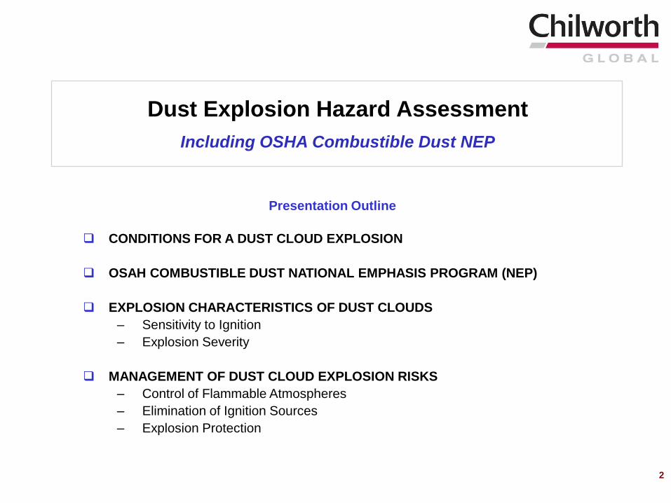
Presentation Outline
CONDITIONS FOR A DUST CLOUD EXPLOSION
OSAH COMBUSTIBLE DUST NATIONAL EMPHASIS PROGRAM (NEP)
EXPLOSION CHARACTERISTICS OF DUST CLOUDS
– Sensitivity to Ignition
– Explosion Severity
MANAGEMENT OF DUST CLOUD EXPLOSION RISKS
– Control of Flammable Atmospheres
– Elimination of Ignition Sources
– Explosion Protection
2
Dust Explosion Hazard Assessment
Including OSHA Combustible Dust NEP
3
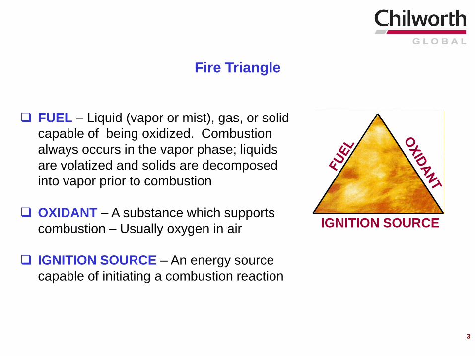
FUEL – Liquid (vapor or mist), gas, or solid
capable of being oxidized. Combustion
always occurs in the vapor phase; liquids
are volatized and solids are decomposed
into vapor prior to combustion
OXIDANT – A substance which supports
combustion – Usually oxygen in air
IGNITION SOURCE – An energy source
capable of initiating a combustion reaction
IGNITION SOURCE
Fire Triangle
4
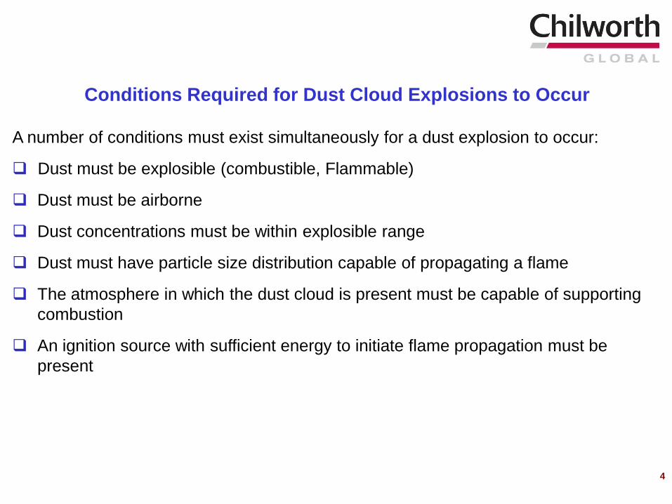
A number of conditions must exist simultaneously for a dust explosion to occur:
Dust must be explosible (combustible, Flammable)
Dust must be airborne
Dust concentrations must be within explosible range
Dust must have particle size distribution capable of propagating a flame
The atmosphere in which the dust cloud is present must be capable of supporting
combustion
An ignition source with sufficient energy to initiate flame propagation must be
present
Conditions Required for Dust Cloud Explosions to Occur
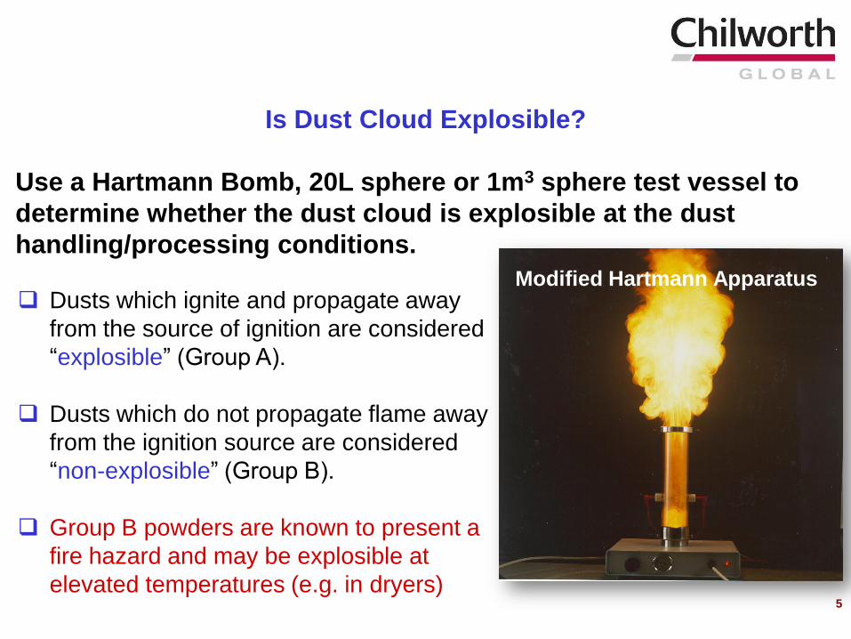
Is Dust Cloud Explosible?
Use a Hartmann Bomb, 20L sphere or 1m3 sphere test vessel to
determine whether the dust cloud is explosible at the dust
handling/processing conditions.
Dusts which ignite and propagate away
from the source of ignition are considered
“explosible” (Group A).
Dusts which do not propagate flame away
from the ignition source are considered
“non-explosible” (Group B).
Group B powders are known to present a
fire hazard and may be explosible at
elevated temperatures (e.g. in dryers)
Modified Hartmann Apparatus
5
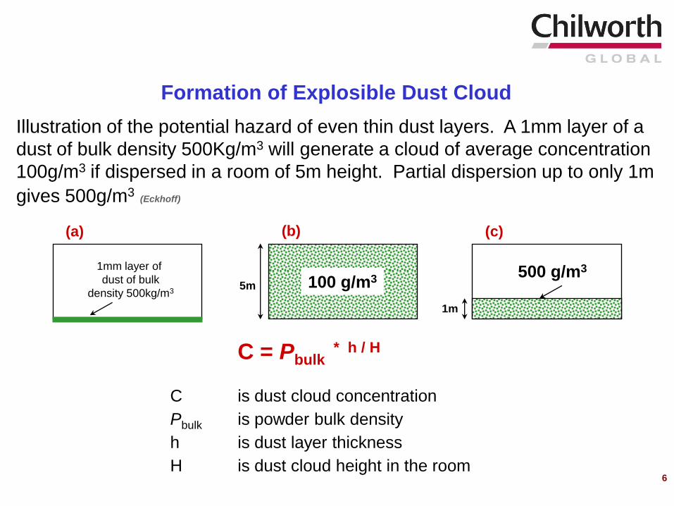
Illustration of the potential hazard of even thin dust layers. A 1mm layer of a
dust of bulk density 500Kg/m3 will generate a cloud of average concentration
100g/m3 if dispersed in a room of 5m height. Partial dispersion up to only 1m
gives 500g/m3(Eckhoff)
C is dust cloud concentration
Pbulk is powder bulk density
h is dust layer thickness
H is dust cloud height in the room
Formation of Explosible Dust Cloud
C = Pbulk * h / H
(a) (c)
1mm layer of
dust of bulk
density 500kg/m3
500 g/m3
1m
(b)
5m 100 g/m3
6
7
When combustible dust and flammable vapors co-exist
Hybrid mixture is hazardous for the following reasons:
When combustible dusts and flammable gas/vapor mixtures are present below
their respective flammable limits, they may form an explosible (hybrid)
atmosphere when mixed together
Dust mixtures in the presence of flammable vapors/gases may be more easily
ignitable in air, even if the concentration of the vapor/gas is below its LFL
Materials (powders) that are too coarse to be explosible may become explosible
when in the presence of a flammable vapor/gas even if the vapor/gas is below its
LFL
Hybrid Mixtures
8
OSHA Combustible Dust National Emphasis Program (NEP)
CPL 03-00-008, March 11th, 2008
The purpose of this NEP is to inspect facilities that generate or handle combustible
dusts which pose a deflagration or other fire hazard when suspended in air or some
other oxidizing medium over a range of concentrations, regardless of particle size or
shape
9
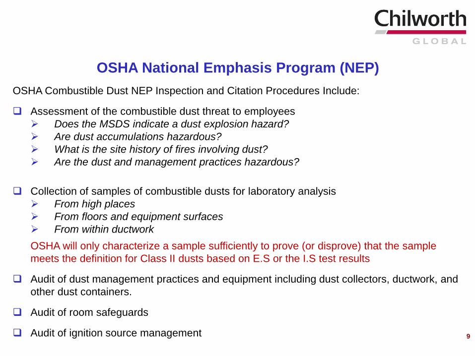
OSHA Combustible Dust NEP Inspection and Citation Procedures Include:
Assessment of the combustible dust threat to employees
Does the MSDS indicate a dust explosion hazard?
Are dust accumulations hazardous?
What is the site history of fires involving dust?
Are the dust and management practices hazardous?
Collection of samples of combustible dusts for laboratory analysis
From high places
From floors and equipment surfaces
From within ductwork
OSHA will only characterize a sample sufficiently to prove (or disprove) that the sample
meets the definition for Class II dusts based on E.S or the I.S test results
Audit of dust management practices and equipment including dust collectors, ductwork, and
other dust containers.
Audit of room safeguards
Audit of ignition source management
OSHA National Emphasis Program (NEP)
10
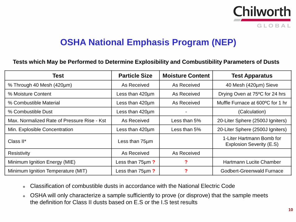
Test Particle Size Moisture Content Test Apparatus
% Through 40 Mesh (420µm) As Received As Received 40 Mesh (420µm) Sieve
% Moisture Content Less than 420µm As Received Drying Oven at 75ºC for 24 hrs
% Combustible Material Less than 420µm As Received Muffle Furnace at 600ºC for 1 hr
% Combustible Dust Less than 420µm - (Calculation)
Max. Normalized Rate of Pressure Rise - Kst As Received Less than 5% 20-Liter Sphere (2500J Igniters)
Min. Explosible Concentration Less than 420µm Less than 5% 20-Liter Sphere (2500J Igniters)
Class II* Less than 75µm1-Liter Hartmann Bomb for
Explosion Severity (E.S)
Resistivity As Received As Received
Minimum Ignition Energy (MIE) Less than 75µm ? ? Hartmann Lucite Chamber
Minimum Ignition Temperature (MIT) Less than 75µm ? ? Godbert-Greenwald Furnace
Classification of combustible dusts in accordance with the National Electric Code
OSHA will only characterize a sample sufficiently to prove (or disprove) that the sample meets
the definition for Class II dusts based on E.S or the I.S test results
Tests which May be Performed to Determine Explosibility and Combustibility Parameters of Dusts
OSHA National Emphasis Program (NEP)
11
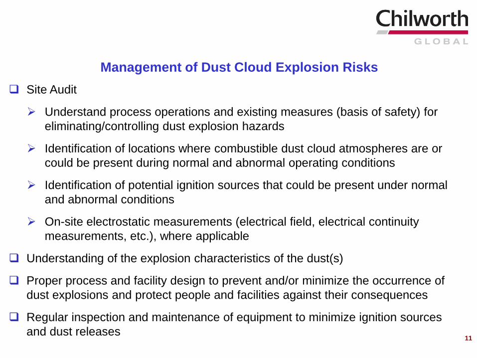
Site Audit
Understand process operations and existing measures (basis of safety) for
eliminating/controlling dust explosion hazards
Identification of locations where combustible dust cloud atmospheres are or
could be present during normal and abnormal operating conditions
Identification of potential ignition sources that could be present under normal
and abnormal conditions
On-site electrostatic measurements (electrical field, electrical continuity
measurements, etc.), where applicable
Understanding of the explosion characteristics of the dust(s)
Proper process and facility design to prevent and/or minimize the occurrence of
dust explosions and protect people and facilities against their consequences
Regular inspection and maintenance of equipment to minimize ignition sources
and dust releases
Management of Dust Cloud Explosion Risks
Flammability of Dust Cloud Atmospheres
12
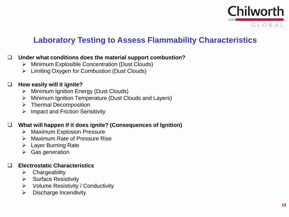
13
Under what conditions does the material support combustion?
Minimum Explosible Concentration (Dust Clouds)
Limiting Oxygen for Combustion (Dust Clouds)
How easily will it ignite?
Minimum Ignition Energy (Dust Clouds)
Minimum Ignition Temperature (Dust Clouds and Layers)
Thermal Decomposition
Impact and Friction Sensitivity
What will happen if it does ignite? (Consequences of Ignition)
Maximum Explosion Pressure
Maximum Rate of Pressure Rise
Layer Burning Rate
Gas generation
Electrostatic Characteristics
Chargeability
Surface Resistivity
Volume Resistivity / Conductivity
Discharge Incendivity
Laboratory Testing to Assess Flammability Characteristics
14
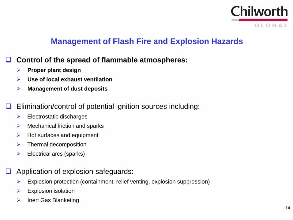
Control of the spread of flammable atmospheres:
Proper plant design
Use of local exhaust ventilation
Management of dust deposits
Elimination/control of potential ignition sources including:
Electrostatic discharges
Mechanical friction and sparks
Hot surfaces and equipment
Thermal decomposition
Electrical arcs (sparks)
Application of explosion safeguards:
Explosion protection (containment, relief venting, explosion suppression)
Explosion isolation
Inert Gas Blanketing
Management of Flash Fire and Explosion Hazards
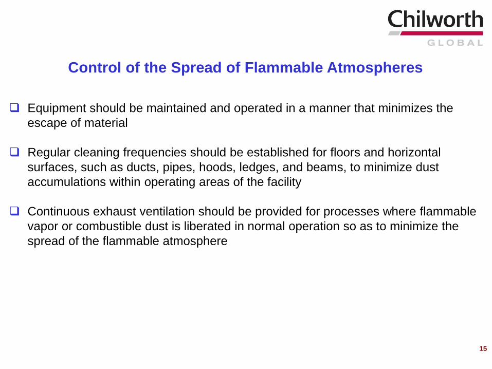
Equipment should be maintained and operated in a manner that minimizes the
escape of material
Regular cleaning frequencies should be established for floors and horizontal
surfaces, such as ducts, pipes, hoods, ledges, and beams, to minimize dust
accumulations within operating areas of the facility
Continuous exhaust ventilation should be provided for processes where flammable
vapor or combustible dust is liberated in normal operation so as to minimize the
spread of the flammable atmosphere
Control of the Spread of Flammable Atmospheres
15
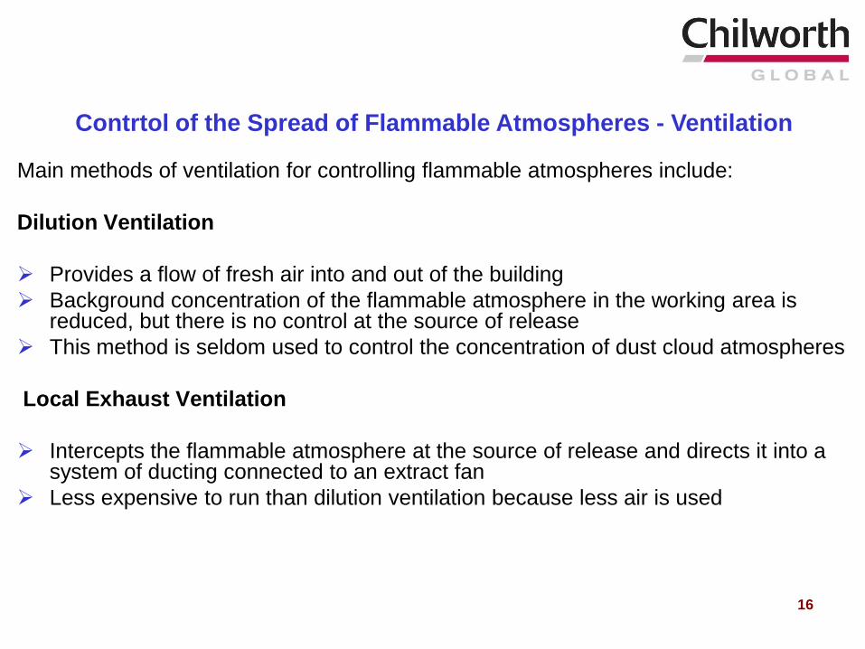
Main methods of ventilation for controlling flammable atmospheres include:
Dilution Ventilation
Provides a flow of fresh air into and out of the building
Background concentration of the flammable atmosphere in the working area is reduced, but there is no control at the source of release
This method is seldom used to control the concentration of dust cloud atmospheres
Local Exhaust Ventilation
Intercepts the flammable atmosphere at the source of release and directs it into a system of ducting connected to an extract fan
Less expensive to run than dilution ventilation because less air is used
Contrtol of the Spread of Flammable Atmospheres - Ventilation
16
17
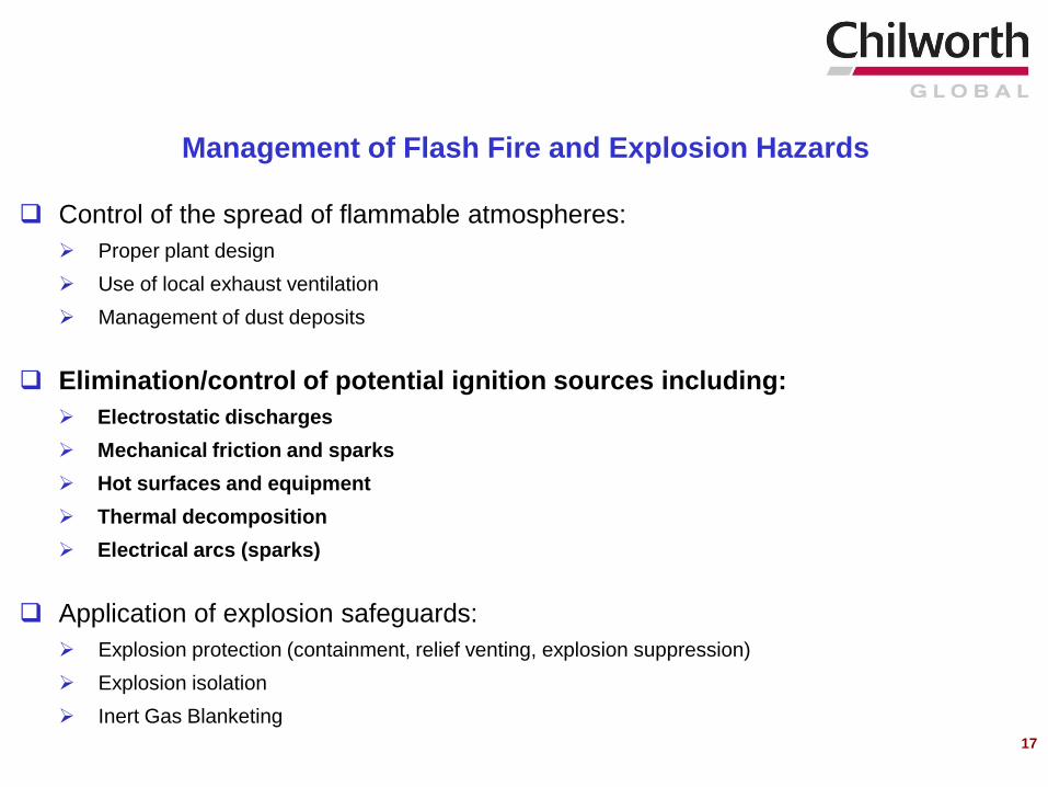
Control of the spread of flammable atmospheres:
Proper plant design
Use of local exhaust ventilation
Management of dust deposits
Elimination/control of potential ignition sources including:
Electrostatic discharges
Mechanical friction and sparks
Hot surfaces and equipment
Thermal decomposition
Electrical arcs (sparks)
Application of explosion safeguards:
Explosion protection (containment, relief venting, explosion suppression)
Explosion isolation
Inert Gas Blanketing
Management of Flash Fire and Explosion Hazards

18
Electrostatic Discharges
Elimination / Control of Potential Ignition Sources
19
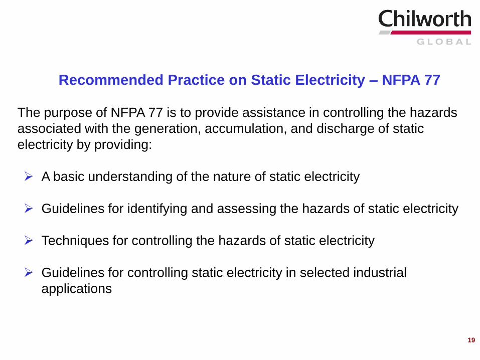
The purpose of NFPA 77 is to provide assistance in controlling the hazards
associated with the generation, accumulation, and discharge of static
electricity by providing:
A basic understanding of the nature of static electricity
Guidelines for identifying and assessing the hazards of static electricity
Techniques for controlling the hazards of static electricity
Guidelines for controlling static electricity in selected industrial
applications
Recommended Practice on Static Electricity – NFPA 77
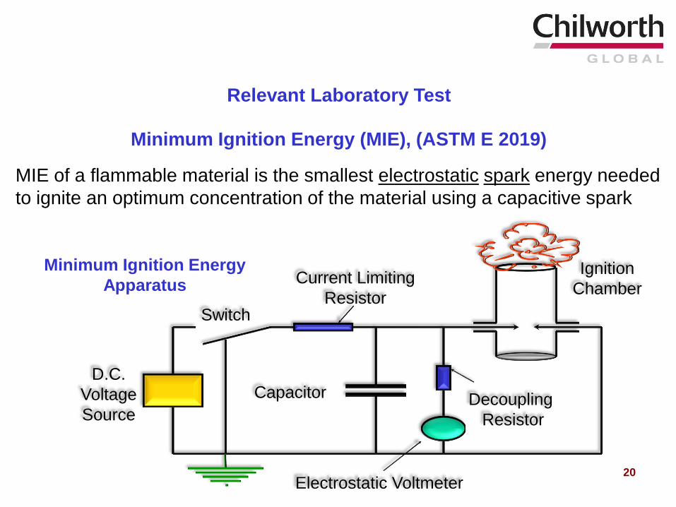
Minimum Ignition Energy
Apparatus
Minimum Ignition Energy (MIE), (ASTM E 2019)
MIE of a flammable material is the smallest electrostatic spark energy needed
to ignite an optimum concentration of the material using a capacitive spark
Electrostatic Voltmeter
Switch
D.C.
Voltage
Source
Current Limiting
Resistor
Capacitor
Ignition
Chamber
Decoupling
Resistor
Relevant Laboratory Test
20
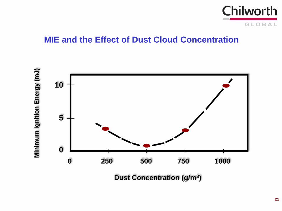
MIE and the Effect of Dust Cloud Concentration
Dust Concentration (g/m3)
Min
imu
m I
gn
itio
n E
nerg
y (
mJ)
0 250 500 750 1000
10
5
0
21
22
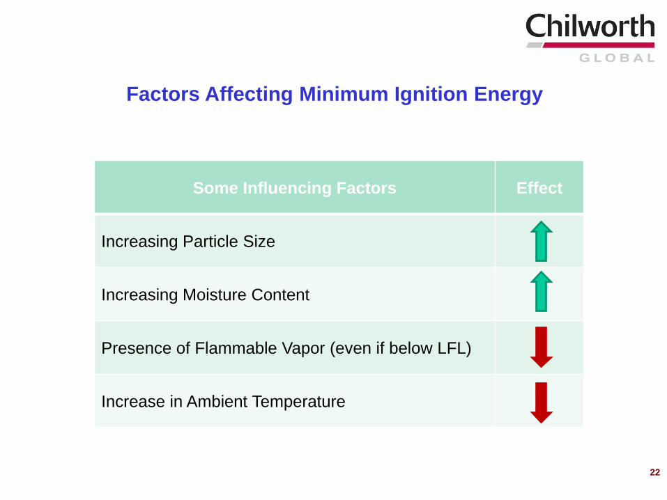
Some Influencing Factors Effect
Increasing Particle Size
Increasing Moisture Content
Presence of Flammable Vapor (even if below LFL)
Increase in Ambient Temperature
Factors Affecting Minimum Ignition Energy
23
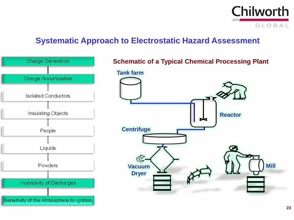
Systematic Approach to Electrostatic Hazard Assessment
Tank farm
Centrifuge
Reactor
Vacuum
Dryer
Mill
Schematic of a Typical Chemical Processing Plant
24
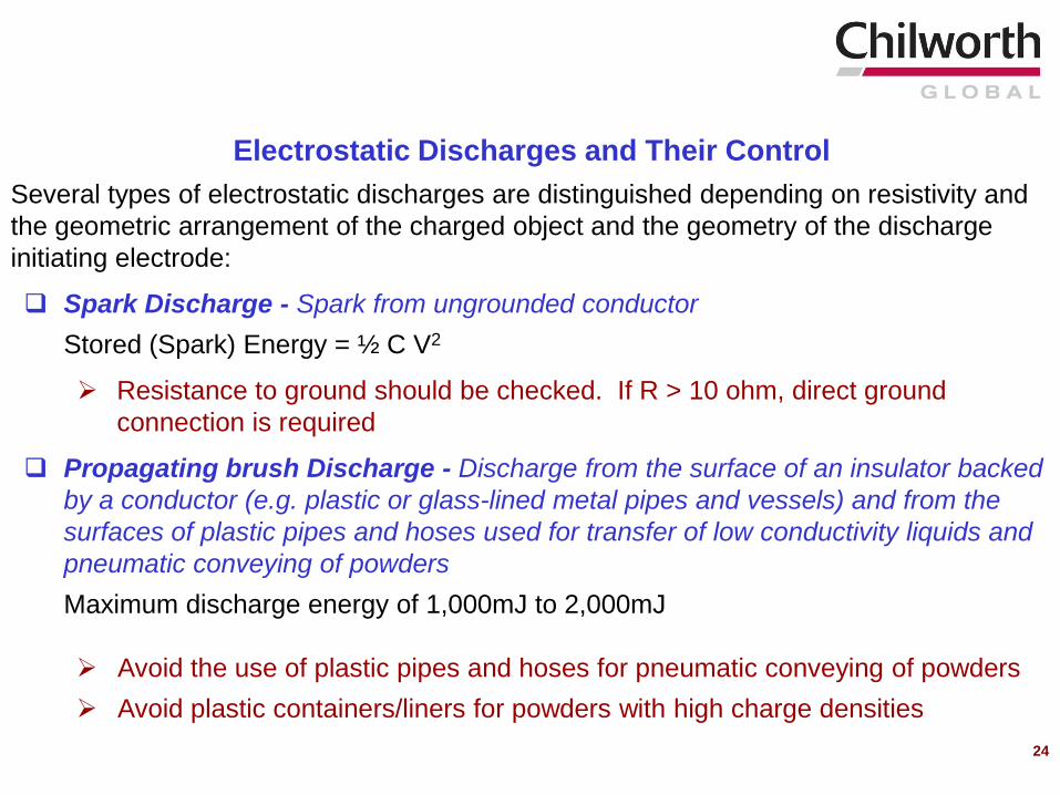
Several types of electrostatic discharges are distinguished depending on resistivity and
the geometric arrangement of the charged object and the geometry of the discharge
initiating electrode:
Spark Discharge - Spark from ungrounded conductor
Stored (Spark) Energy = ½ C V2
Resistance to ground should be checked. If R > 10 ohm, direct ground
connection is required
Propagating brush Discharge - Discharge from the surface of an insulator backed
by a conductor (e.g. plastic or glass-lined metal pipes and vessels) and from the
surfaces of plastic pipes and hoses used for transfer of low conductivity liquids and
pneumatic conveying of powders
Maximum discharge energy of 1,000mJ to 2,000mJ
Avoid the use of plastic pipes and hoses for pneumatic conveying of powders
Avoid plastic containers/liners for powders with high charge densities
Electrostatic Discharges and Their Control
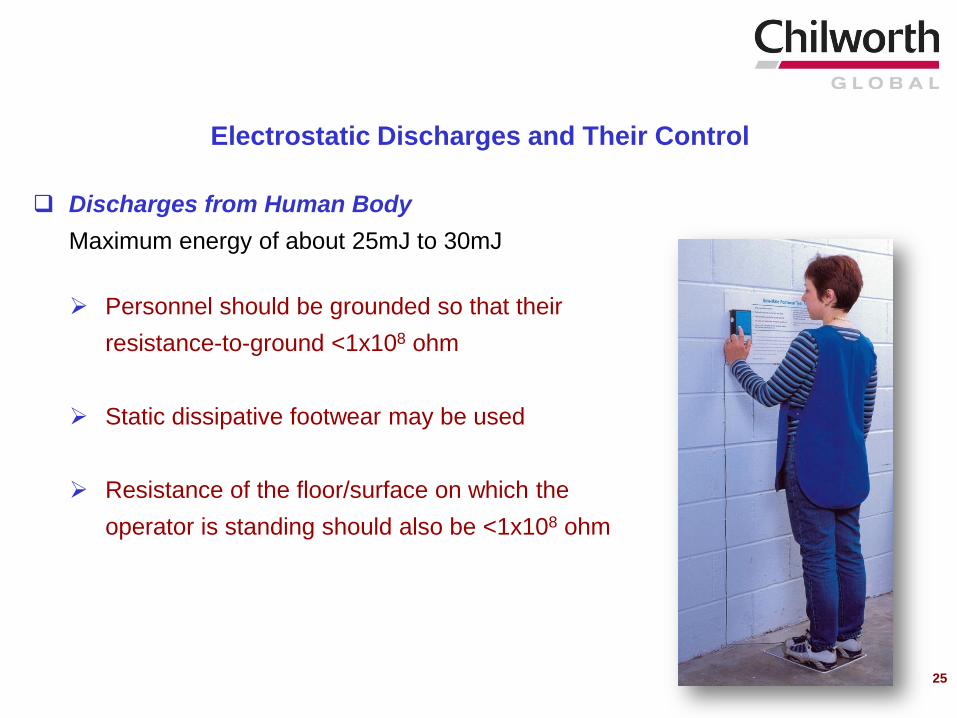
25
Discharges from Human Body
Maximum energy of about 25mJ to 30mJ
Personnel should be grounded so that their
resistance-to-ground <1x10⁸ ohm
Static dissipative footwear may be used
Resistance of the floor/surface on which the
operator is standing should also be <1x10⁸ ohm
Electrostatic Discharges and Their Control
26
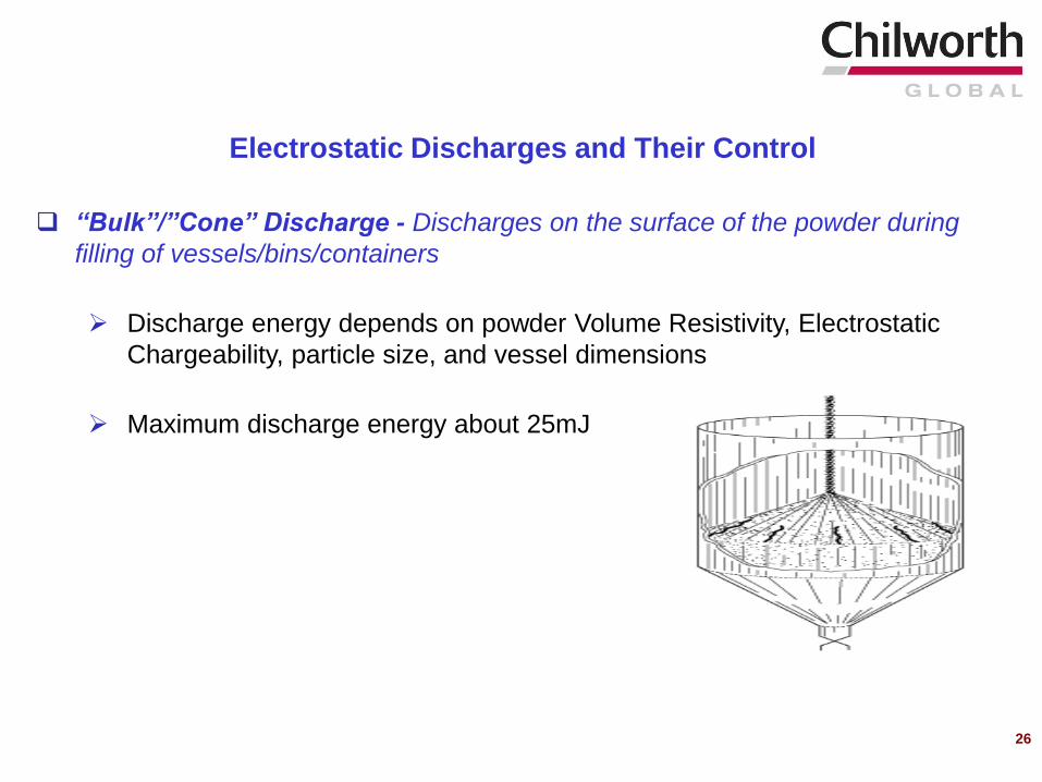
“Bulk”/”Cone” Discharge - Discharges on the surface of the powder during
filling of vessels/bins/containers
Discharge energy depends on powder Volume Resistivity, Electrostatic
Chargeability, particle size, and vessel dimensions
Maximum discharge energy about 25mJ
Electrostatic Discharges and Their Control
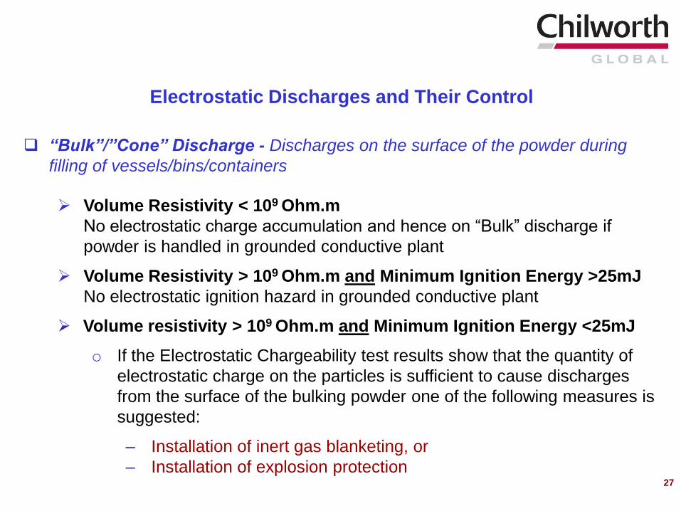
“Bulk”/”Cone” Discharge - Discharges on the surface of the powder during
filling of vessels/bins/containers
Volume Resistivity < 109 Ohm.m
No electrostatic charge accumulation and hence on “Bulk” discharge if
powder is handled in grounded conductive plant
Volume Resistivity > 109 Ohm.m and Minimum Ignition Energy >25mJ
No electrostatic ignition hazard in grounded conductive plant
Volume resistivity > 109 Ohm.m and Minimum Ignition Energy <25mJ
o If the Electrostatic Chargeability test results show that the quantity of
electrostatic charge on the particles is sufficient to cause discharges
from the surface of the bulking powder one of the following measures is
suggested:
– Installation of inert gas blanketing, or
– Installation of explosion protection
Electrostatic Discharges and Their Control
27
“Brush” Discharge - Discharges Between Conductors and Insulators
Maximum discharge energy of 4mJ
Brush discharges are capable of igniting flammable gas and vapor
atmospheres
Avoid the use of insulating (non-conductive) materials where flammable gas
and vapor atmospheres might be present. Examples of insulating materials
include plastic hoses, bags, liners, drums
Consider conductive or static dissipative materials (Surface Resistivity
< 1x10¹¹ ohm/square)
Electrostatic Discharges and Their Control
28
29
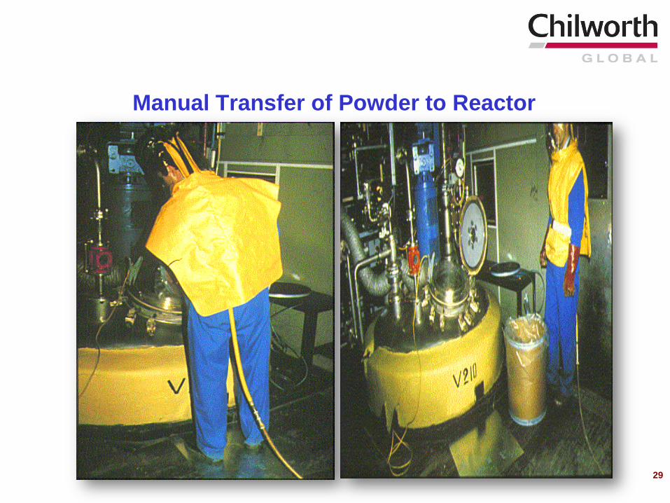
Manual Transfer of Powder to Reactor
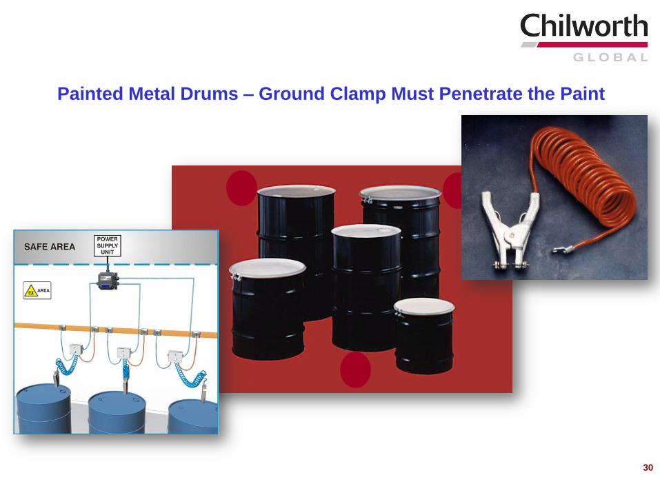
30
Painted Metal Drums – Ground Clamp Must Penetrate the Paint
31
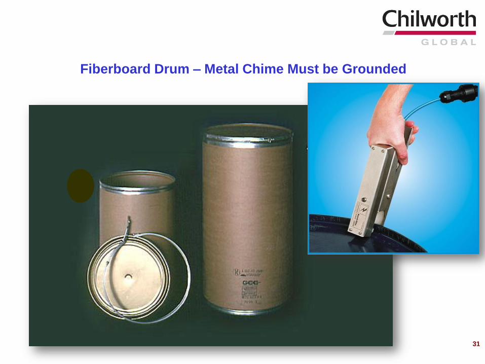
Fiberboard Drum – Metal Chime Must be Grounded
32
Mechanical friction and sparks
Hot surfaces and equipment
Thermal decomposition
Elimination / Control of Potential Ignition Sources

If the material is subjected to heat as part of the normal process (e.g. during
drying), the temperature should be maintained below the self heating temperature
Isolation or shielding of hot surfaces
Use of approved electrical equipment (correct temperature rating)
Prevent overheating due to misalignment, loose objects, belt-slip/rubbing etc. by
regular inspection and maintenance of plant
Prevention/removal of dust accumulations on hot surfaces
Preventing overloading of processing plant (grinders, conveyors, etc.)
Prevent foreign material from entering the system when such foreign material
presents an ignition hazard. Consider use of screens, electromagnets, pneumatic
separators, etc.
Hot work operations should be controlled by a hot work permit system in
accordance with NFPA 51B, Standard for Fire Prevention During Welding, Cutting
and Other Hot Work
Control of Heat Sources and Frictional Sparks
33

Ignition of bulk powders can occur by a process of self-heating
Ignition occurs when the temperature of the powder is raised to a level at which the
heat liberated by the exothermic reaction is sufficient to exceed the heat losses and
to produce runaway increase in temperature
The minimum ambient temperature for self-ignition of a powder depends mainly on
the nature of the powder and on its dimensions
Thermal Instability (Self-Heating)
34
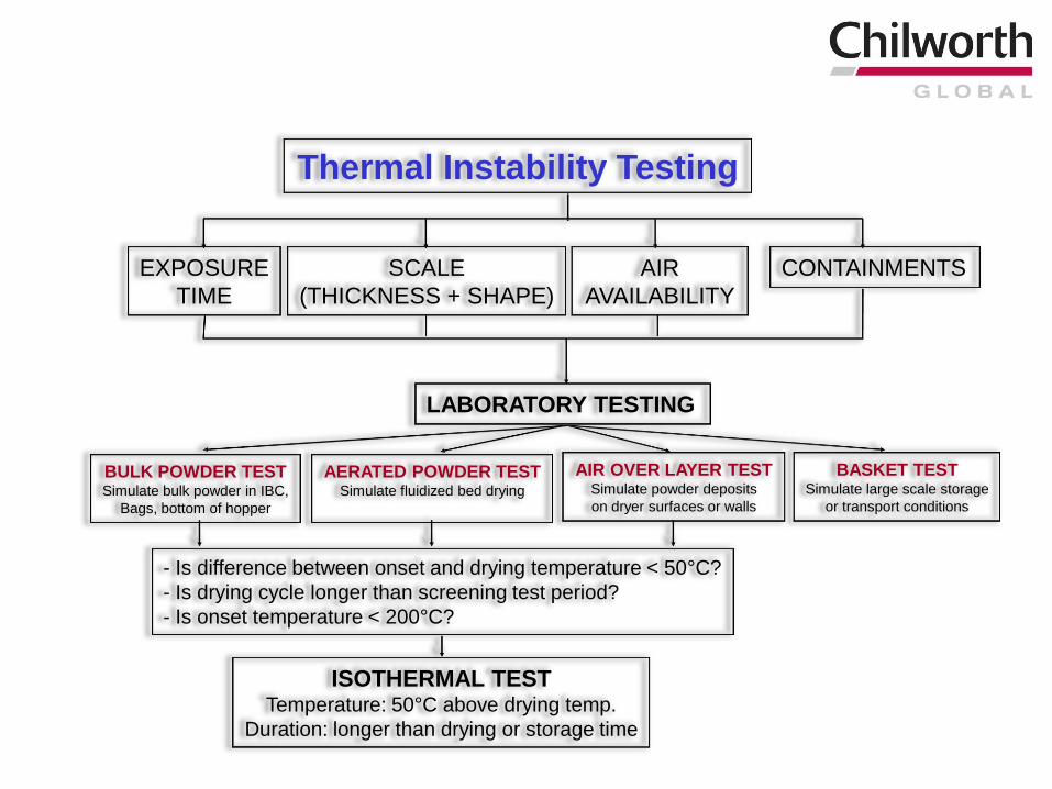
Thermal Instability Testing
EXPOSURE
TIME
SCALE
(THICKNESS + SHAPE)
AIR
AVAILABILITY
CONTAINMENTS
LABORATORY TESTING
BULK POWDER TESTSimulate bulk powder in IBC,
Bags, bottom of hopper
AERATED POWDER TESTSimulate fluidized bed drying
AIR OVER LAYER TESTSimulate powder deposits
on dryer surfaces or walls
BASKET TESTSimulate large scale storage
or transport conditions
- Is difference between onset and drying temperature < 50°C?
- Is drying cycle longer than screening test period?
- Is onset temperature < 200°C?
ISOTHERMAL TESTTemperature: 50°C above drying temp.
Duration: longer than drying or storage time
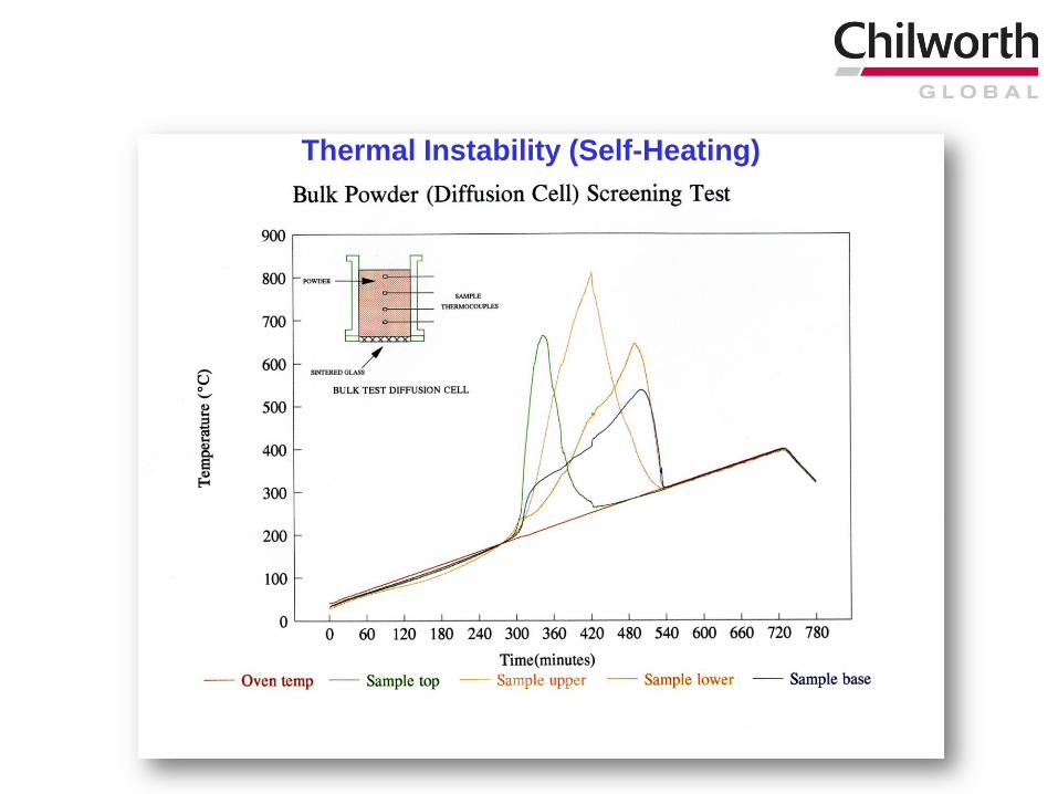
36
Thermal Instability (Self-Heating)
Electrical arcs (sparks)
Elimination / Control of Potential Ignition Sources
37

Incorrectly specified electrical equipment is a potent ignition source for flammable gases, vapors and dusts
Sparks
Hot surfaces
In facilities handling flammable materials the electrical equipment used must be suitable for the environment in which it is to be used
In order to determine the type of equipment it is necessary to define hazardous (classified) locations
Elimination/Control of Potential Ignition Sources – Electrical Equipment
38
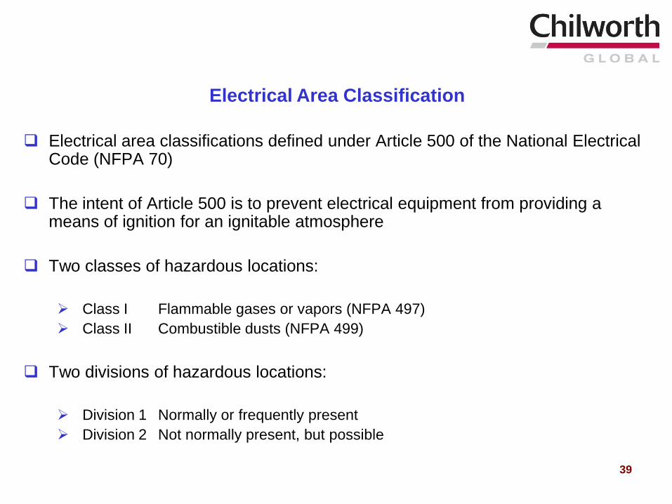
Electrical area classifications defined under Article 500 of the National Electrical Code (NFPA 70)
The intent of Article 500 is to prevent electrical equipment from providing a means of ignition for an ignitable atmosphere
Two classes of hazardous locations:
Class I Flammable gases or vapors (NFPA 497)
Class II Combustible dusts (NFPA 499)
Two divisions of hazardous locations:
Division 1 Normally or frequently present
Division 2 Not normally present, but possible
Electrical Area Classification
39
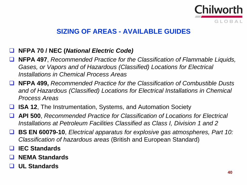
SIZING OF AREAS - AVAILABLE GUIDES
NFPA 70 / NEC (National Electric Code)
NFPA 497, Recommended Practice for the Classification of Flammable Liquids,
Gases, or Vapors and of Hazardous (Classified) Locations for Electrical
Installations in Chemical Process Areas
NFPA 499, Recommended Practice for the Classification of Combustible Dusts
and of Hazardous (Classified) Locations for Electrical Installations in Chemical
Process Areas
ISA 12, The Instrumentation, Systems, and Automation Society
API 500, Recommended Practice for Classification of Locations for Electrical
Installations at Petroleum Facilities Classified as Class I, Division 1 and 2
BS EN 60079-10, Electrical apparatus for explosive gas atmospheres, Part 10:
Classification of hazardous areas (British and European Standard)
IEC Standards
NEMA Standards
UL Standards40
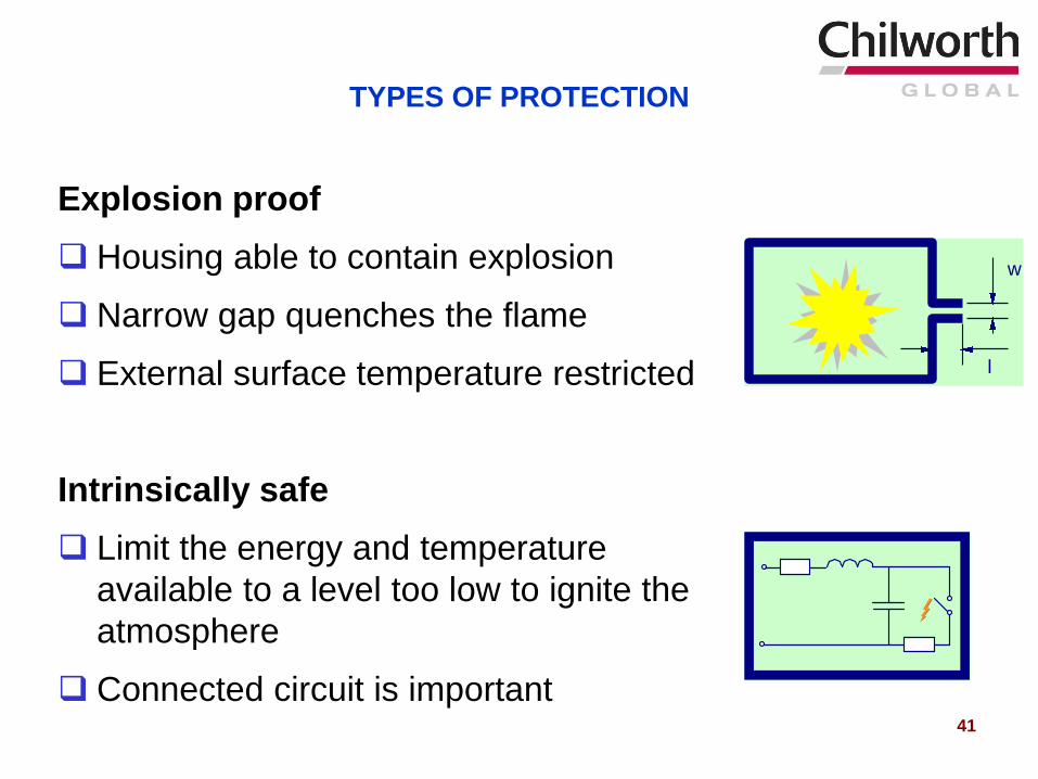
TYPES OF PROTECTION
Explosion proof
Housing able to contain explosion
Narrow gap quenches the flame
External surface temperature restricted
Intrinsically safe
Limit the energy and temperature
available to a level too low to ignite the
atmosphere
Connected circuit is important
w
l
41
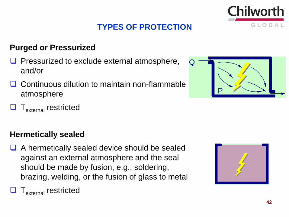
TYPES OF PROTECTION
Purged or Pressurized
Pressurized to exclude external atmosphere,
and/or
Continuous dilution to maintain non-flammable
atmosphere
Texternal restricted
Hermetically sealed
A hermetically sealed device should be sealed
against an external atmosphere and the seal
should be made by fusion, e.g., soldering,
brazing, welding, or the fusion of glass to metal
Texternal restricted
P
Q
42
TYPES OF PROTECTION
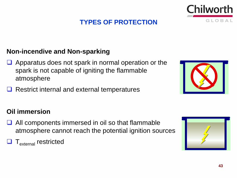
Non-incendive and Non-sparking
Apparatus does not spark in normal operation or the
spark is not capable of igniting the flammable
atmosphere
Restrict internal and external temperatures
Oil immersion
All components immersed in oil so that flammable
atmosphere cannot reach the potential ignition sources
Texternal restricted
43
44
Management of Dust Cloud Explosion Hazards
Control of the spread of combustible dust atmospheres:
Proper plant design
Use of local exhaust ventilation
Management of dust deposits
Elimination/control of potential ignition sources including:
Electrostatic discharges
Mechanical friction and sparks
Hot surfaces and equipment
Thermal decomposition
Electrical arcs (sparks)
Application of explosion safeguards:
Explosion protection (containment, relief venting, explosion suppression)
Explosion isolation
Inert Gas Blanketing
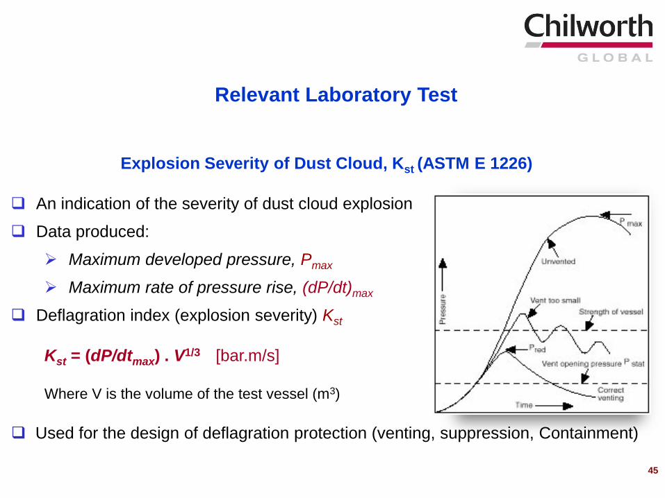
Explosion Severity of Dust Cloud, Kst (ASTM E 1226)
An indication of the severity of dust cloud explosion
Data produced:
Maximum developed pressure, Pmax
Maximum rate of pressure rise, (dP/dt)max
Deflagration index (explosion severity) Kst
Kst = (dP/dtmax) . V1/3 [bar.m/s]
Where V is the volume of the test vessel (m3)
Used for the design of deflagration protection (venting, suppression, Containment)
Relevant Laboratory Test
20-Liter Sphere Apparatus
45
46
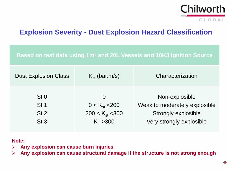
Based on test data using 1m3 and 20L Vessels and 10KJ Ignition Source
Dust Explosion Class Kst (bar.m/s) Characterization
St 0
St 1
St 2
St 3
0
0 < Kst <200
200 < Kst <300
Kst >300
Non-explosible
Weak to moderately explosible
Strongly explosible
Very strongly explosible
Explosion Severity - Dust Explosion Hazard Classification
Note:
Any explosion can cause burn injuries
Any explosion can cause structural damage if the structure is not strong enough
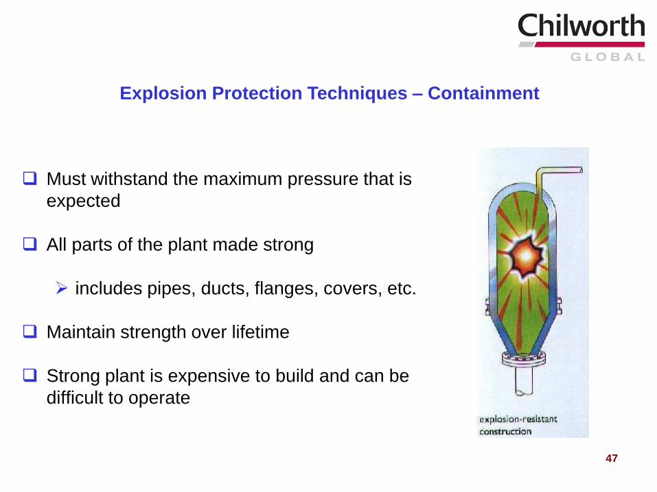
Must withstand the maximum pressure that is
expected
All parts of the plant made strong
includes pipes, ducts, flanges, covers, etc.
Maintain strength over lifetime
Strong plant is expensive to build and can be
difficult to operate
Explosion Protection Techniques – Containment
47
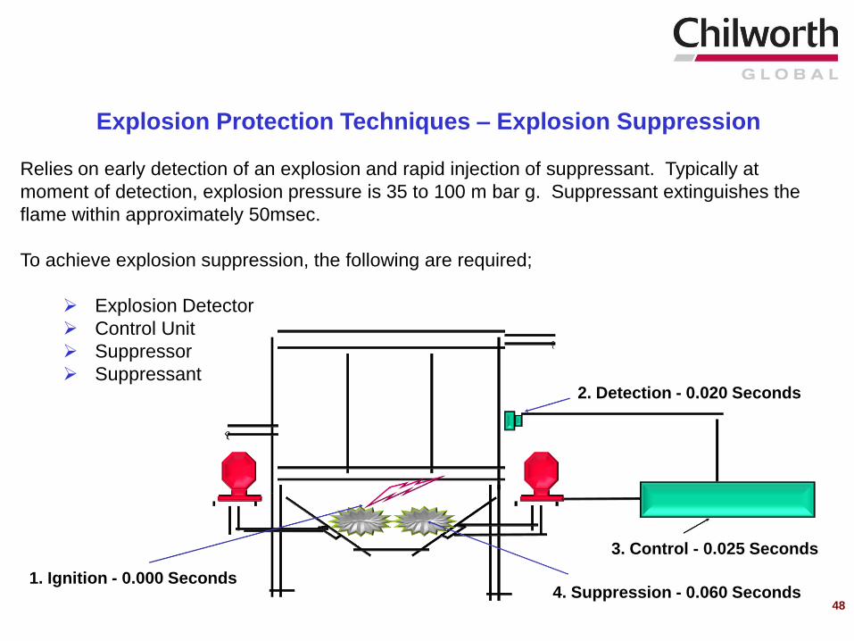
4. Suppression - 0.060 Seconds 1. Ignition - 0.000 Seconds
2. Detection - 0.020 Seconds
3. Control - 0.025 Seconds
Explosion Protection Techniques – Explosion Suppression
Relies on early detection of an explosion and rapid injection of suppressant. Typically at
moment of detection, explosion pressure is 35 to 100 m bar g. Suppressant extinguishes the
flame within approximately 50msec.
To achieve explosion suppression, the following are required;
Explosion Detector
Control Unit
Suppressor
Suppressant
48
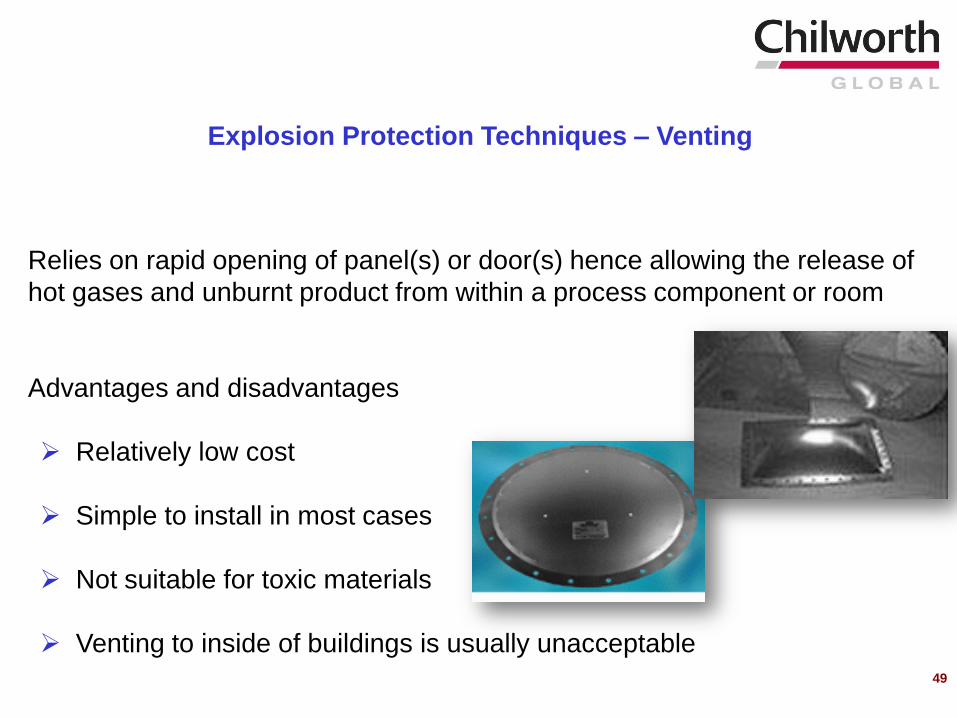
Relies on rapid opening of panel(s) or door(s) hence allowing the release of
hot gases and unburnt product from within a process component or room
Advantages and disadvantages
Relatively low cost
Simple to install in most cases
Not suitable for toxic materials
Venting to inside of buildings is usually unacceptable
Explosion Protection Techniques – Venting
49
An explosion, initiated in one plant item should be prevented from
propagating along pipes, chutes, conveyors etc. and starting a subsequent
explosion in other plant items.
The simplest isolation method is avoidance of unnecessary connections. If
this is not possible, special measures should be taken to create barriers to
avoid propagation of an explosion.
– Mechanical Isolation (Barriers)
– Chemical Isolation (Barriers)
Explosion Protection Techniques - Isolation
50
An explosion (or fire) can be prevented by reducing the oxidant concentration below a
level that will no longer support combustion through the addition of an inert gas to the
vessel where the flammable/combustible atmosphere exists.
There are 3 commonly used inerting techniques:
Pressure Purging
Vessel is pressurized with an inert gas, then relieved to the outside. This procedure
is repeated until the desired oxygen concentration is reached.
Vacuum Purging
Vessel is evacuated and then pressure is increased to atmospheric using an inert
gas.
Flow-Through Purging
Vessel is purged with a continuous flow of inert gas.
Inert Gas Blanketing Techniques - NFPA 69
51
52
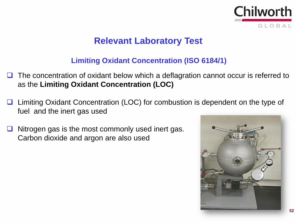
Relevant Laboratory Test
Limiting Oxidant Concentration (ISO 6184/1)
The concentration of oxidant below which a deflagration cannot occur is referred to
as the Limiting Oxidant Concentration (LOC)
Limiting Oxidant Concentration (LOC) for combustion is dependent on the type of
fuel and the inert gas used
Nitrogen gas is the most commonly used inert gas.
Carbon dioxide and argon are also used
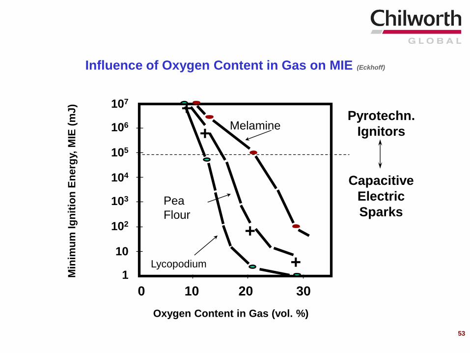
+
+
+
+
Lycopodium
Pea
Flour
MelaminePyrotechn.
Ignitors
Capacitive
Electric
Sparks
Oxygen Content in Gas (vol. %)
0 10 20 30
Min
imu
m I
gn
itio
n E
nerg
y, M
IE (
mJ)
Influence of Oxygen Content in Gas on MIE (Eckhoff)
107
106
105
104
103
102
10
1
53
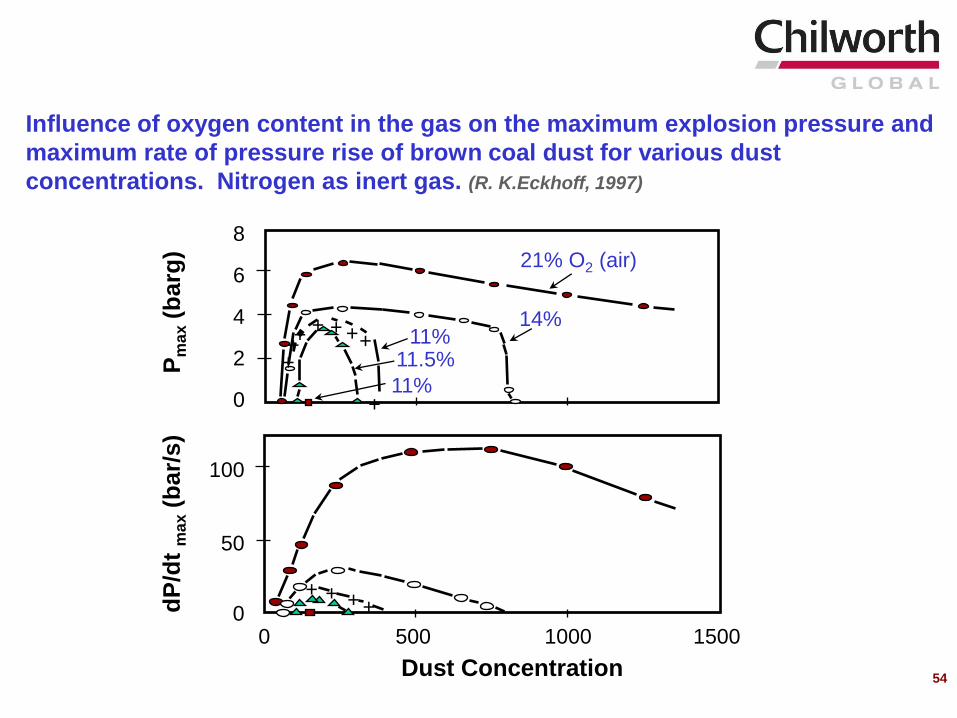
Influence of oxygen content in the gas on the maximum explosion pressure and
maximum rate of pressure rise of brown coal dust for various dust
concentrations. Nitrogen as inert gas. (R. K.Eckhoff, 1997)
Dust Concentration
Pm
ax
(barg
)
0 500 1000 1500
++++
dP
/dt
ma
x(b
ar/
s)
+
+++++++
21% O2 (air)
14% 11%
11.5%
11%
8
6
4
2
0
100
50
0
54
55
Industries handling and processing explosible dusts must be fully aware of Best
Industry Practices as described in pertinent dust Codes and Standards, and follow
these recommendations. Relevant codes and standards include:
NFPA 61, “Standard for the Prevention of Fires and Dust Explosions in Agricultural and Food
Products Facilities”
NFPA 68, “Guide for Venting of Deflagrations”
NFPA 69, “Standard on Explosion Prevention Systems”
NFPA 77, “Recommended Practice on Static Electricity”
NFPA 484, “Standard for Combustible Metals, Metal Powders, and Metal Dusts”
NFPA 499, “ Recommended Practice for the Classification of Combustible Dusts and of
Hazardous (Classified) Locations for Electrical Installations in Chemical Process Areas”
NFPA 654, “Standard for the Prevention of Fire and Dust Explosions from the Manufacturing,
Processing and Handling of Combustible Particulate Solids”
NFPA 655, “Standard for Prevention of Sulfur Fires and Explosions”
NFPA 664, “Standard for the Prevention of Fires and Explosions in Wood Processing and
Woodworking Facilities”
Best Industry Practices
56
VAHID EBADAT, PH.D.
Chilworth Technology, Inc.
250 Plainsboro Road, Building #7
Plainsboro, NJ 08536
e-mail: [email protected]
Presentation at
Metropolitan New York AIHA Local Section
October 16th, 2009
New York, NY
Dust Explosion Hazard Assessment
Including OSHA Combustible Dust NEP
56
ISO/IEC 17025 & GLP Accredited Laboratories
Chilworth Technology
Process Safety Consulting, Testing, Training, Engineering, and Management
www.chilworth.com
ISO/IEC 17025 & GLP Accredited Laboratories
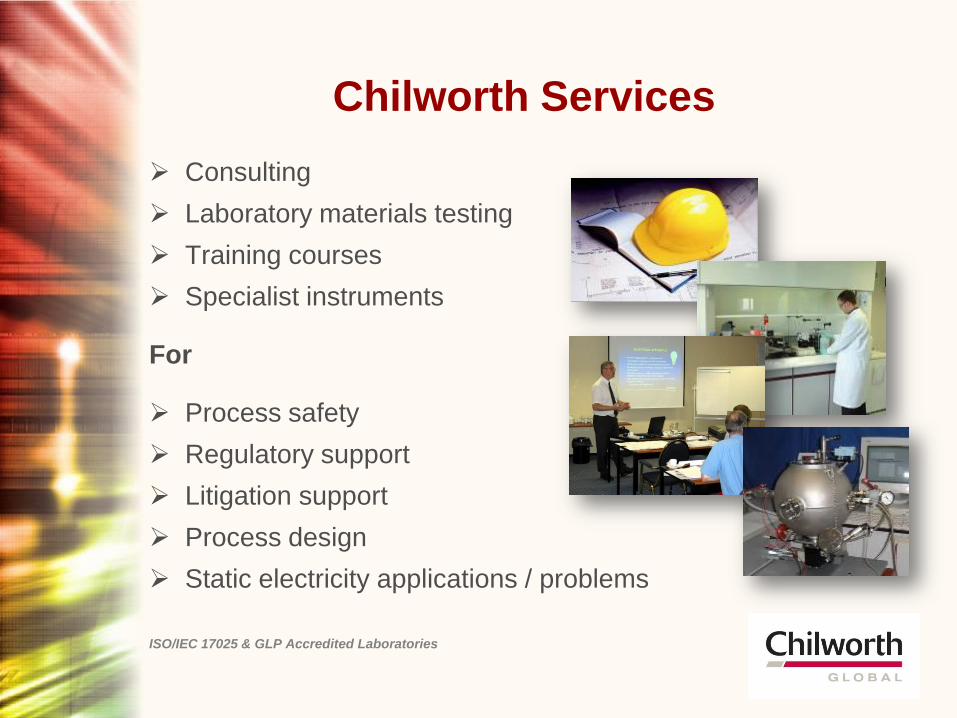
Chilworth Services
Consulting
Laboratory materials testing
Training courses
Specialist instruments
For
Process safety
Regulatory support
Litigation support
Process design
Static electricity applications / problems
ISO/IEC 17025 & GLP Accredited Laboratories
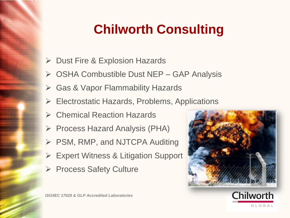
Chilworth Consulting
Dust Fire & Explosion Hazards
OSHA Combustible Dust NEP – GAP Analysis
Gas & Vapor Flammability Hazards
Electrostatic Hazards, Problems, Applications
Chemical Reaction Hazards
Process Hazard Analysis (PHA)
PSM, RMP, and NJTCPA Auditing
Expert Witness & Litigation Support
Process Safety Culture
ISO/IEC 17025 & GLP Accredited Laboratories
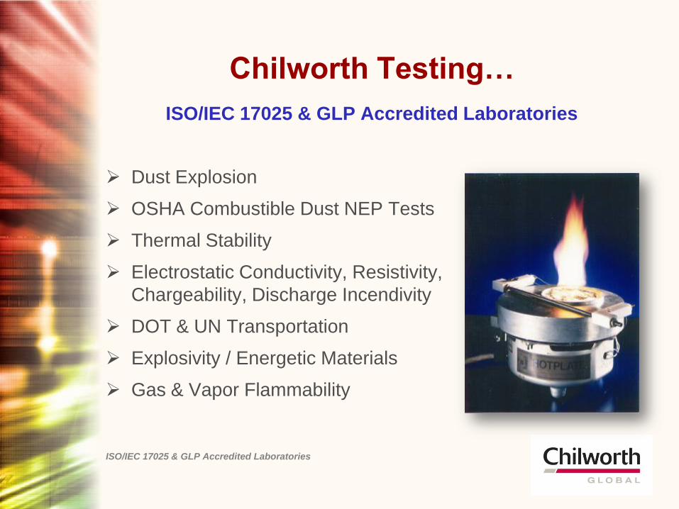
Chilworth Testing…
ISO/IEC 17025 & GLP Accredited Laboratories
Dust Explosion
OSHA Combustible Dust NEP Tests
Thermal Stability
Electrostatic Conductivity, Resistivity,
Chargeability, Discharge Incendivity
DOT & UN Transportation
Explosivity / Energetic Materials
Gas & Vapor Flammability
ISO/IEC 17025 & GLP Accredited Laboratories
ISO/IEC 17025 & GLP Accredited Laboratories
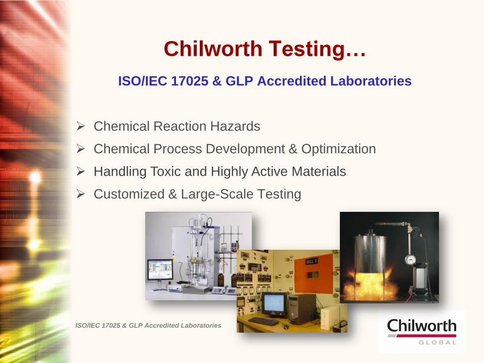
Chemical Reaction Hazards
Chemical Process Development & Optimization
Handling Toxic and Highly Active Materials
Customized & Large-Scale Testing
Chilworth Testing…
ISO/IEC 17025 & GLP Accredited Laboratories
Specialist Testing
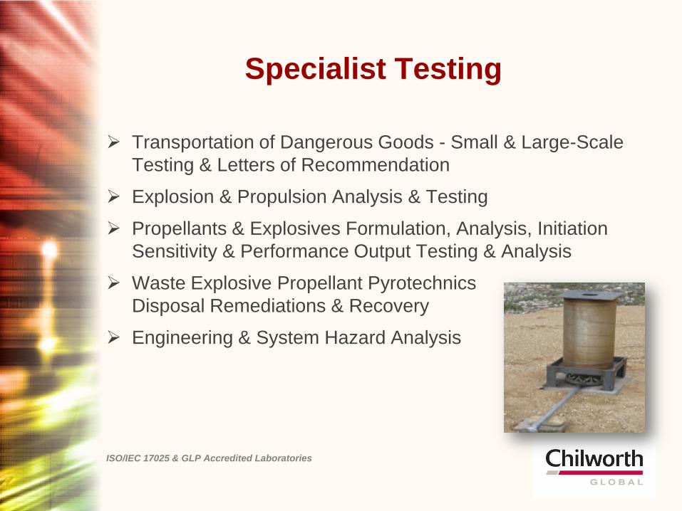
Transportation of Dangerous Goods - Small & Large-Scale
Testing & Letters of Recommendation
Explosion & Propulsion Analysis & Testing
Propellants & Explosives Formulation, Analysis, Initiation
Sensitivity & Performance Output Testing & Analysis
Waste Explosive Propellant Pyrotechnics
Disposal Remediations & Recovery
Engineering & System Hazard Analysis
ISO/IEC 17025 & GLP Accredited Laboratories
Regulatory Support
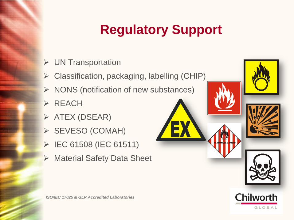
UN Transportation
Classification, packaging, labelling (CHIP)
NONS (notification of new substances)
REACH
ATEX (DSEAR)
SEVESO (COMAH)
IEC 61508 (IEC 61511)
Material Safety Data Sheet
ISO/IEC 17025 & GLP Accredited Laboratories
Fire Service
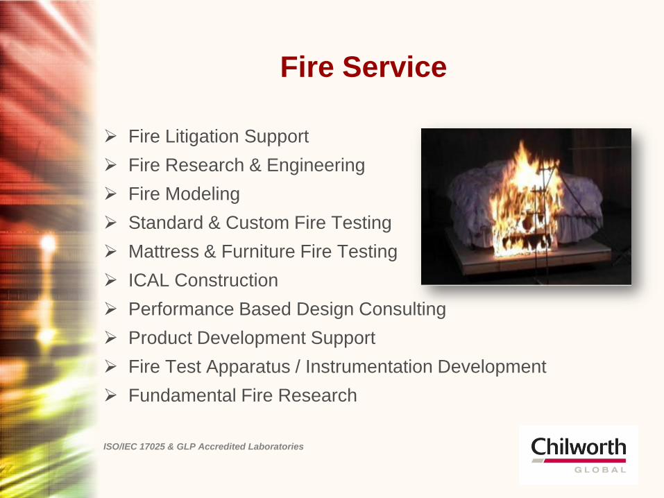
Fire Litigation Support
Fire Research & Engineering
Fire Modeling
Standard & Custom Fire Testing
Mattress & Furniture Fire Testing
ICAL Construction
Performance Based Design Consulting
Product Development Support
Fire Test Apparatus / Instrumentation Development
Fundamental Fire Research
ISO/IEC 17025 & GLP Accredited Laboratories
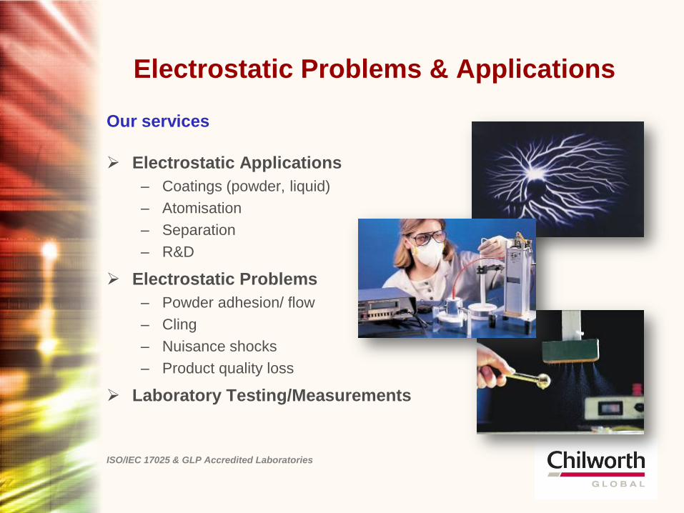
Electrostatic Problems & Applications
Our services
Electrostatic Applications
– Coatings (powder, liquid)
– Atomisation
– Separation
– R&D
Electrostatic Problems
– Powder adhesion/ flow
– Cling
– Nuisance shocks
– Product quality loss
Laboratory Testing/Measurements
ISO/IEC 17025 & GLP Accredited Laboratories
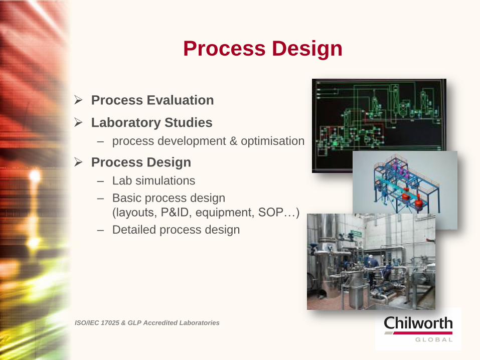
Process Design
Process Evaluation
Laboratory Studies
– process development & optimisation
Process Design
– Lab simulations
– Basic process design
(layouts, P&ID, equipment, SOP…)
– Detailed process design
ISO/IEC 17025 & GLP Accredited Laboratories
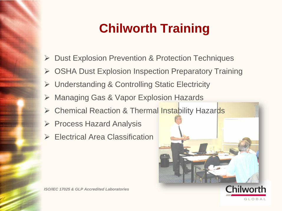
Chilworth Training
Dust Explosion Prevention & Protection Techniques
OSHA Dust Explosion Inspection Preparatory Training
Understanding & Controlling Static Electricity
Managing Gas & Vapor Explosion Hazards
Chemical Reaction & Thermal Instability Hazards
Process Hazard Analysis
Electrical Area Classification
ISO/IEC 17025 & GLP Accredited Laboratories
Litigation support
Our clients
Law firms
Manufacturing companies
Insurance carriers
Origin & cause
investigators
Government agencies
Our services
Expert advice for litigation
support
Laboratory investigations
Origin & cause
investigation
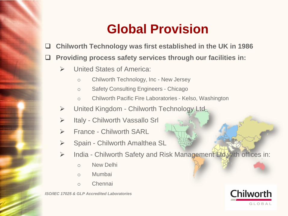
Global Provision
Chilworth Technology was first established in the UK in 1986
Providing process safety services through our facilities in:
United States of America:
o Chilworth Technology, Inc - New Jersey
o Safety Consulting Engineers - Chicago
o Chilworth Pacific Fire Laboratories - Kelso, Washington
United Kingdom - Chilworth Technology Ltd
Italy - Chilworth Vassallo Srl
France - Chilworth SARL
Spain - Chilworth Amalthea SL
India - Chilworth Safety and Risk Management Ltd with offices in:
o New Delhi
o Mumbai
o Chennai
ISO/IEC 17025 & GLP Accredited Laboratories
Client Industries
Agrochemicals
Chemicals
Engineering/ consultants
Fine Chemicals
Food & Drink
Government
Wood / Paper
Legal / Insurance
Metals
Personal & Household
Products
Oil & Petrochemical
Pharmaceuticals
Plastics & Rubber
Coal Fired Power
Generating plants
ISO/IEC 17025 & GLP Accredited Laboratories

ISO/IEC 17025 & GLP Accredited Laboratories
Chilworth Technology
Process Safety Consulting, Testing, Training, Engineering, and Management
www.chilworth.com