Combined SCR – A novel approach for NOx and PM aftertreatment · A novel approach for NOx and PM...
21
13. ETH-Conference on Combustion Generated Nanoparticles , Zürich, 22.-24.06.2009 Combined SCR – A novel approach for NOx and PM aftertreatment M. Müller 1 , S. Schraml , P. Broll, H. Bülte, DEUTZ AG, Ottostr. 1, 51149 Cologne, Germany H. Harndorf, University of Rostock, Albert-Einstein-Str. 2 , 18059 Rostock, Germany To meet the requirements of future emission legislation engine manufacturers will have to offer a complete system consisting of an advanced diesel engine and an aftertreatment unit. Future exhaust aftertreatment systems will most probably contain a selective catalytic reduction catalyst (SCR) as well as a diesel particulate filter (DPF) to cope with stringent NOx and PM emission limits. For off-road applications, DEUTZ has the ambition to couple all active aftertreatment components directly to the engine in order to minimize the number of variants and thus to lower application efforts. In compliance with the EU Stage 4 and US Tier 4 emission limits, DEUTZ investigates a novel approach with the target to realize a compact and cost optimised emission control system. The exhaust aftertreatment concept, which is named "Combined SCR", essentially consists of a burner-vaporiser unit, a V 2 O 5 -coated SCR-catalyst and a coated diesel particulate filter (cDPF). The employment of the burner-vaporiser unit on the one hand enables to exceed an exhaust gas temperature which upstream of the SCR-catalyst is greater than 300°C within the entire engine operation map. On the other hand, the vaporization enthalpy for additionally injected diesel fuel is provided. The diesel vapour is homogeneously mixed with engine exhaust gas, which allows excellent transport of chemically bound energy within the exhaust system and thus lowers engineering efforts for different applications. A specific element of the concept is that the SCR-catalyst also serves as an oxidation catalyst for the diesel vapour during thermal DPF regeneration. The described compact system configuration allows not only to reduce nitrogen oxides (NOx) but also to generate heat by at least partial oxidation of hydrocarbons. The target temperature of approximately 600°C upstream the DPF is reached in three steps. The first temperature increase of the exhaust gas will be achieved by the burner, which has a constant thermal power. This heat release ensures light-off temperature for the subsequent catalytic process and fuel vaporization. In the second stage around 30-60% of the chemically bound energy is released from partial oxidation of the hydrocarbons on the SCR catalyst. 1 corresponding author, Email: [email protected]
Transcript of Combined SCR – A novel approach for NOx and PM aftertreatment · A novel approach for NOx and PM...

13. ETH-Conference on Combustion Generated Nanoparticles , Zürich, 22.-24.06.2009
Combined SCR – A novel approach for NOx and PM aftertreatment M. Müller1, S. Schraml , P. Broll, H. Bülte, DEUTZ AG, Ottostr. 1, 51149 Cologne, Germany H. Harndorf, University of Rostock, Albert-Einstein-Str. 2 , 18059 Rostock, Germany
To meet the requirements of future emission legislation engine manufacturers will have to
offer a complete system consisting of an advanced diesel engine and an aftertreatment
unit. Future exhaust aftertreatment systems will most probably contain a selective catalytic
reduction catalyst (SCR) as well as a diesel particulate filter (DPF) to cope with stringent
NOx and PM emission limits. For off-road applications, DEUTZ has the ambition to couple
all active aftertreatment components directly to the engine in order to minimize the number
of variants and thus to lower application efforts. In compliance with the EU Stage 4 and US
Tier 4 emission limits, DEUTZ investigates a novel approach with the target to realize a
compact and cost optimised emission control system.
The exhaust aftertreatment concept, which is named "Combined SCR", essentially
consists of a burner-vaporiser unit, a V2O5 -coated SCR-catalyst and a coated diesel
particulate filter (cDPF). The employment of the burner-vaporiser unit on the one hand
enables to exceed an exhaust gas temperature which upstream of the SCR-catalyst is
greater than 300°C within the entire engine operation map. On the other hand, the
vaporization enthalpy for additionally injected diesel fuel is provided. The diesel vapour is
homogeneously mixed with engine exhaust gas, which allows excellent transport of
chemically bound energy within the exhaust system and thus lowers engineering efforts for
different applications.
A specific element of the concept is that the SCR-catalyst also serves as an oxidation
catalyst for the diesel vapour during thermal DPF regeneration. The described compact
system configuration allows not only to reduce nitrogen oxides (NOx) but also to generate
heat by at least partial oxidation of hydrocarbons. The target temperature of approximately
600°C upstream the DPF is reached in three steps. The first temperature increase of the
exhaust gas will be achieved by the burner, which has a constant thermal power. This heat
release ensures light-off temperature for the subsequent catalytic process and fuel
vaporization. In the second stage around 30-60% of the chemically bound energy is
released from partial oxidation of the hydrocarbons on the SCR catalyst.
1 corresponding author, Email: [email protected]

13. ETH-Conference on Combustion Generated Nanoparticles , Zürich, 22.-24.06.2009
This in particular is a special feature of the hydrocarbons from the DEUTZ burner-
vaporizer unit. The remaining chemical energy, in a great portion bound to carbon
monoxide, is preferably released downstream the SCR on the cDPF. By extended test
bench investigations it has been shown that there is no degradation neither on SCR nor on
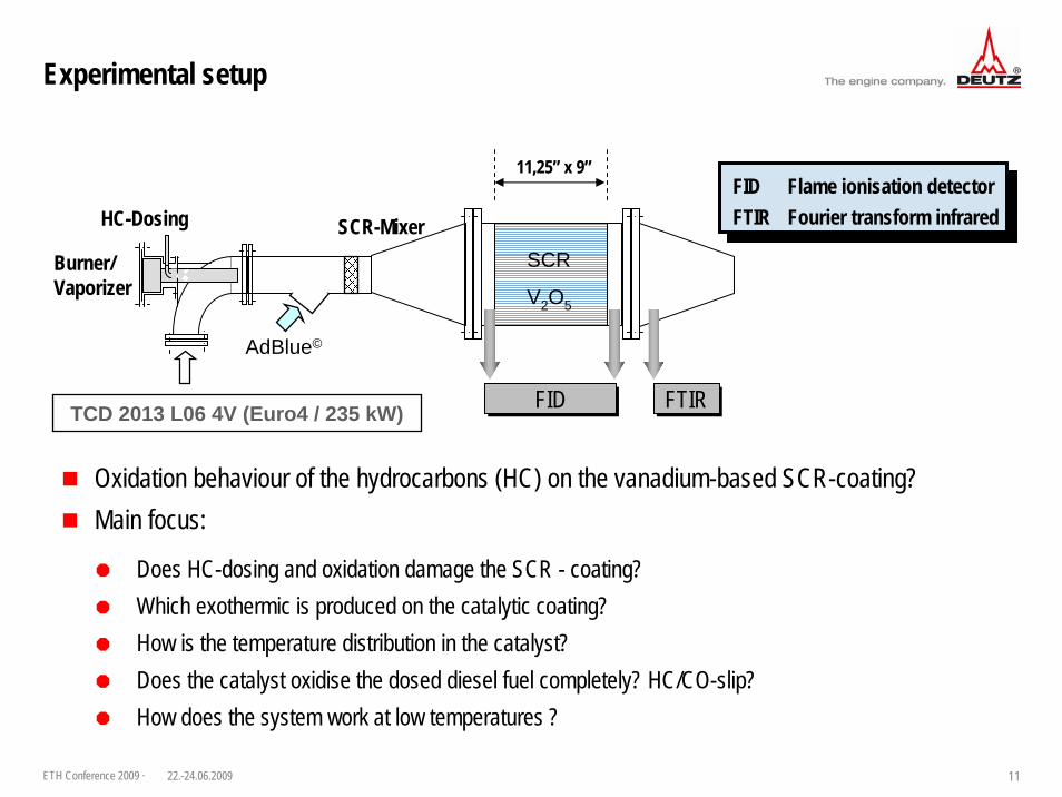
heat-up performance observed. In the figure below, a typical setup is shown for integrating
the combined SCR system to a complete Tier4 exhaust aftertreatment system.
Figure 1: Experimental test setup
As the burner/vaporizer unit ensures sufficiently high exhaust temperatures for all given
operation conditions, one of the main benefits of this system configuration is the
applicability for a broad variety of applications with no restrictions and without the need for
an additional heat mode calibration. Further, the SCR catalyst in front of the DPF allows
high NOx conversion rates even for cold cycles and the application of vanadium-based
technologies which – in contrast to zeolite SCR systems – gained a high maturity level and
offers high NOx conversion rates at moderate costs. Especially cold cycle SCR
performance is one of the key aspects for forthcoming emission legislations as the NOx
certification values have to be met for very challenging certification cycles. As a
consequence, the lack of the passive regeneration feature against the well known SCRT
configuration, which will be broadly used for Euro 6 on-road applications, can at least be
partly compensated by an advanced engine calibration. Further features and experimental
results of the combined SCR approach will be presented in more detail within this
presentation.
Tem
pe
ratu
re [
°C]
325
375
425
475
525
575
625
675
725
Time [min]
0 10 20 30 40 50 60
Burner/
Vaporizer
HC-Dosing
SCR
AdBlue©
SCR-Mixer
ASC CDPF
11,25” x 9” x 4” 11,25” x 12”
FIDFID FTIRFTIR AMA (2-line)AMA (2-line)
Tupstream SCR Tdownstram SCR Tdownstram ASC Tdownstram DPF
SCRQ&SCRQ&
ASCQ&
CDPFQ&
ASCQ&ASCQ&
CDPFQ&CDPFQ&

Combined SCR – A novel approach for Nox and PM aftertreatment13. ETH-Conference on Combustion Generated Nanoparticles (22.-24.06.2009)
M.Müller, Dr. H.Bülte, Dr. S.Schraml, Dr. P.Broll, DEUTZ AG, Cologne Prof. Dr. H.Harndorf, University of Rostock

ETH Conference 2009 · 222.-24.06.2009
Content
Introduction………………………………………………………………………………...3System - concepts for off-road emission regulations..........................................….. 8A novel approach - Combined SCR……………………………………………………. 10Experimental setup………………………………………………………………………. 11Test results………………………………………………………………………………...12Summary and outlook…………………………………………………………………….19
Slide

ETH Conference 2009 · 322.-24.06.2009
Introduction
Construction Infrastructure
NutritionAgriculture
Daily demandCommercial
DEUTZ manufactures engines for different applications in a power range of 9 – 500 kW…

ETH Conference 2009 · 422.-24.06.2009
Totally different market requests for the different applications concerning:
TechnologyPerformanceLoad profilesMaintenance
Future exhaust aftertreatment systems will most probably comprise selective catalytic reduction (SCR) as well as wall-flow diesel particulate filters (DPF) to cope with stringent NOx and PM emission limits
DEUTZ will offer a complete system consisting of the diesel engine and the aftertreatment unit with the target to realize a compact and cost optimised system to meet the emission standards
Minimized application effortsMaximized customer value
Introduction
High number of variants of one engine
ETH Conference 2009 · 522.-24.06.2009
Introduction
DEUTZ strategy for forthcoming emission legislation
NOx (+ HC)[g/kWh]
Parti
culat
es [g
/kWh] 0,25
0,20
0,15
0,10
0,05
0,00
0 1 2 3 4 5
DPF98% Optim
ized I
njecti
on,
Comb
ustio
n an
d Tur
boch
argin
g
130 – 560 kW
Features Tier 4 interim (from year 2011)DEUTZ Common Rail (DCR®) 2000 bar Advanced nozzle designWaste gate turbochargerCharge air coolerExternally cooled EGRBurner for DPF regenerationDPF
Additional Features Tier 4 (from year 2014)SCRVGTDual-stage turbocharger w/ and w/o intercooling
TIER 3TIER 3
Tier 4 finalTier 4 final
Tier 4 interimTier 4 interimSCR0,025
0,4

ETH Conference 2009 · 622.-24.06.2009
Active components closed coupled to the engine Space consuming components (catalyst, muffler, acoustics, etc…) located in the machinery
Introduction
DEUTZ strategy for Tier 4 interim
DOC diesel oxidation catalystCDPF coated diesel particulate filter
DOC diesel oxidation catalystCDPF coated diesel particulate filter
Engine
ECU
DosingmoduleFuel
Temperatureupstream/downstream
Air
Pressureupstream/downstream
Burner/Vaporizer ExhaustDOC CDPF
Variants in customer applications
Muffler
ETH Conference 2009 · 722.-24.06.2009
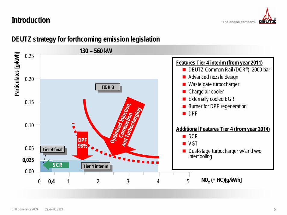
TCD2013 L06 4V Tier4 interim
Heat mode for DPF-regeneration
Key facts of the burner / vaporizer unit:
Introduction
15 kW powerEngine independent preheating of catalystExhaust gas temperature ≥ 300 °C Provides vaporisation enthalpyAdditional HC doser includedHomogeneous dispersion of the vaporized diesel fuel on the catalyst surface
Key facts of the burner / vaporizer unit:
15 kW powerEngine independent preheating of catalystExhaust gas temperature ≥ 300 °C Provides vaporisation enthalpyAdditional HC doser includedHomogeneous dispersion of the vaporized diesel fuel on the catalyst surface
T upstr. DOC ≥ 300°C
T engine out
Heat up by
burner
T light-off DOC≈ 15 kWTe
mpe
ratu
re[°C
]
Time [s]
Heat release by DOC T thermal regeneration
DEUTZ strategy for Tier 4 interim

ETH Conference 2009 · 822.-24.06.2009
Pros and cons:+ Passive DPF-regeneration feasible + Application of the Tier4 interim muffler feasible- AdBlue© - dosing upstream DOC not possible (NH3 oxidation)- AdBlue© - doser cannot be closed coupled to the engine- High application efforts- High precious metal quantity
1st concept: EAT-system consisting of DPF + SCR (SCRT© -configuration)Add-on system to Tier4 interim setup
System concepts for Tier 4 final
System - concepts for off-road emission regulations
CDPFDOC
Burner/vaporizer
DOC diesel oxidation catalystCDPF coated diesel particulate filterSCR selective catalytic reduction cat.ASC ammonia slip catalyst
DOC diesel oxidation catalystCDPF coated diesel particulate filterSCR selective catalytic reduction cat.ASC ammonia slip catalyst
SCR ASC
AdBlue©

ETH Conference 2009 · 922.-24.06.2009
2nd concept: SCR-system upstream DOC and DPF Scope: All active components (HC and AdBlue© dosing unit) coupled close at the engine
System - concepts for off-road emission regulations
Alternative options for Tier 4 final
SCR
AdBlue©
CDPFDOC
HC-Dozer
Does the HC-dosing damage the SCR coating during an active DPF regeneration?
SCR
AdBlue© + HC-Dosing
CDPFDOC
ETH Conference 2009 · 1022.-24.06.2009
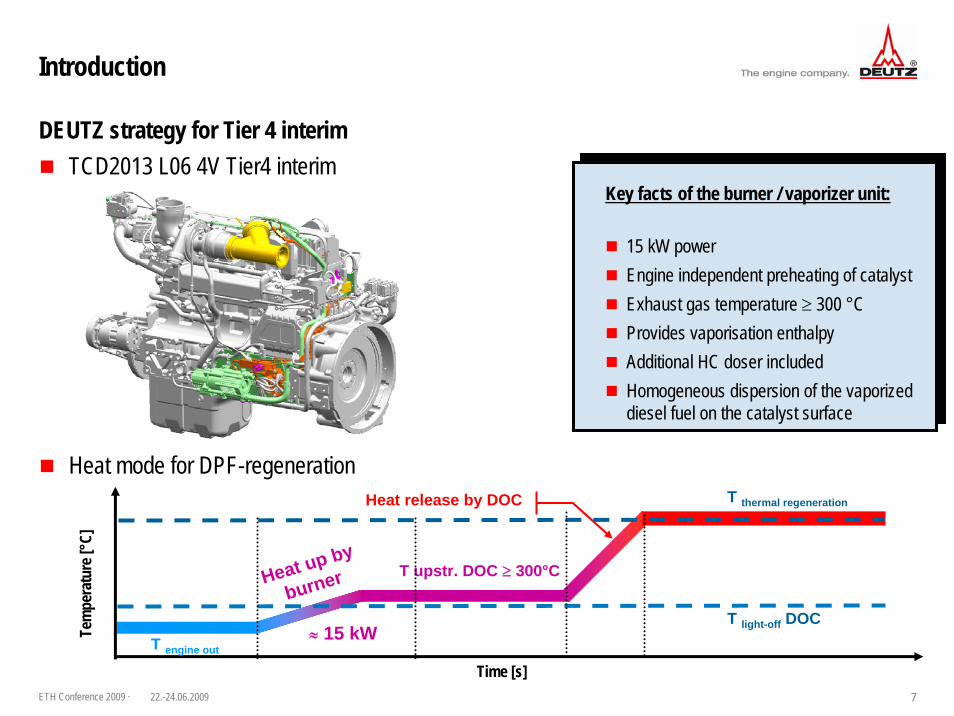
All active components can be mounted at the engineHydrocarbons partially oxidised on the catalytic coating of the SCR – catalyst (V2O5) Heat release for the DPF – regeneration is partially generated by the SCR - coatingNOx – conversion up to 95 % (steady state) in dependency of the engine operating point100 % soot reduction by the DPF (wall-flow)The burner guarantees an exhaust gas temperature ≥ 300 °C within the whole engine mapProbably only one muffler required like TIER4 interim Cost benefit due to saving of precious metal
━ No NO2 formation for passive regeneration (CRT)
A novel approach - Combined SCR
Benefit of the Combined SCR system
SCR
AdBlue©
CDPF
Burner Closed coupled to engine
ASC
ETH Conference 2009 · 1122.-24.06.2009
Oxidation behaviour of the hydrocarbons (HC) on the vanadium-based SCR-coating?Main focus:
Does HC-dosing and oxidation damage the SCR - coating?Which exothermic is produced on the catalytic coating?How is the temperature distribution in the catalyst?Does the catalyst oxidise the dosed diesel fuel completely? HC/CO-slip?How does the system work at low temperatures ?
Experimental setup
FID Flame ionisation detectorFTIR Fourier transform infrared
FID Flame ionisation detectorFTIR Fourier transform infrared
Burner/Vaporizer
HC-Dosing
SCR
V2O5
AdBlue©
SCR-Mixer
11,25” x 9”
FIDFID FTIRFTIRTCD 2013 L06 4V (Euro4 / 235 kW)

ETH Conference 2009 · 1222.-24.06.2009
Test results
Alternating admission of diesel fuel and NH3 to the SCR - coating
Test cycle: Combination of a DPF-regeneration + ESC test cycle, duration: 62 min / cycle295 test cycles were accomplished
HC
-Dos
ing
[ml/m
in]
0
10
20
30
40
50
Time [s]0 500 1000 1500 2000 2500 3000 3500 4000
engi
ne s
peed
[1/m
in] /
torq
ue [N
m]
0
500
1000
1500
2000
2500
Engine speed Engine torque HC-dosing
DPF - regeneration AdBlue© - Dosing

ETH Conference 2009 · 1322.-24.06.2009
Test results
SCR performance after 295 test cycles 300°C / 40000 1/h 400°C / 40000 1/h
NH3 N2O
NO
x co
ncen
trat
ion
[ppm
]
0
200
400
600
800
1000 After aging 145 test cycles 295 test cycles
NO
x-co
nver
sion
rate
[%]
0
20
40
60
80
100
NO
x co
ncen
trat
ion
[ppm
]
0
200
400
600
800
1000
NO
x-co
nver
sion
rate
[%]
0
20
40
60
80
100
NH
3 / N
2O [p
pm]
0
10
20
30
40
50
Feed ratio [-]0.0 0.2 0.4 0.6 0.8 1.0 1.2 1.4 1.6 1.8
NH3 N2O
NH
3 / N
2O [p
pm]
0
10
20
30
40
50
Feed ratio [-]0.0 0.2 0.4 0.6 0.8 1.0 1.2 1.4 1.6 1.8

ETH Conference 2009 · 1422.-24.06.2009
Test results
HC-dosage for a target temperature of 630°C upstream DPF HC conversion [%]
100009000800070006000500040003000200010000
T up
str.
SCR
[°C
]
300
350
400
450
500
550
600
650
90
80
80
7058 627267
74777281
82 8280 80
8183 777979 78
96 73 76
100100 9999100
HC
- co
nver
sion
[%]
1009080706050403020100
T up
str.
SCR
[°C
]
300
350
400
450
500
550
600
650
Space velocity [1/h]10000 20000 30000 40000 50000 60000 70000
2851 32214464417851245942
443156906422 5323
5879 571444595219 394152545810 4952
3623 1675 2523
7231047 10618661411
CO
- co
ncen
trat
ion
[ppm
]
CO downstream SCR [ppm]

ETH Conference 2009 · 1522.-24.06.2009
Test results
Heat generation on the SCR coating / Target temperature upstream DPF of 630°C
T up
str.
SCR
[°C
]
300
350
400
450
500
550
600
650
405 437460443481486
505519486 522
510 523545550 551541537 542
564 578 585
611626 619624634
Tem
pera
ture
dow
nstr
. SC
R [°
C]
600575550525500475450425400
T downstream SCR [°C]
T up
str.
SCR
[°C
]
300
350
400
450
500
550
600
650
Space velocity [1/h]10000 20000 30000 40000 50000 60000 70000
100
25
50
75
125
12597 122139122
146148143147
91 12594 105
104102 977769 69
37 40 36
2820 121116
Hea
t gen
erat
ion
on S
CR
[°C
]
2001751501251007550250
Heat generation on SCR coating [°C]

ETH Conference 2009 · 1622.-24.06.2009
Test results
Axial temperature distribution during the DPF-regeneration at peak HC-dosage
Axial temperature distribution during DPF regeneration (test cycle)10 35 60 85 115 145 170 195 [mm]
0
HC - Dosing FTIR / FIDTe
mpe
ratu
r [°
C]
425
450
475
500
525
550
575
10 35 60 85 115 145 170 195 [mm]0
HC - Dosing
Reg
ener
atio
n tim
e [s
]
Tem
pera
ture
[°C
]
430
450
470
490
510
530
700
500
300
100
600
400
200
0
100
200
300
400
500
600
700
800
FTIR / FID

ETH Conference 2009 · 1722.-24.06.2009
Tem
pera
ture
[°C
]
325
375
425
475
525
575
625
675
725
Time [min]0 10 20 30 40 50 60
Test results
Heat-up performance of the Combined SCR system at max. space velocity of 60000 1/h
Burner/Vaporizer
HC-Dosing
SCR
AdBlue©
SCR-Mixer
ASC CDPF
11,25” x 9” x 4” 11,25” x 12”
FIDFID FTIRFTIR AMA (2-line)AMA (2-line)
SCRQ&
ASCQ&CDPFQ&
1. Heat release by the burner/vaporiser unit2. Heat release from partial oxidising of the hydrocarbons on the SCR coating3. Heat release of the remaining chemical energy on the ASC and CDPF
Tupstream SCR Tdownstram SCR Tdownstram ASC Tdownstram DPF

ETH Conference 2009 · 1822.-24.06.2009
Summary and outlook
HC-oxidation on the SCR coatingThe vanadium-based SCR - coating (V2O5) shows oxidising characteristic and serves as an oxidation catalyst for the diesel vapour during DPF regeneration
The precious metal loadings on the ammonia slip catalyst and the coated DPF can be reduced
The formation of CO is a favourable featureThe high quantities of CO almost completely oxidised on the ASC + CDPF.
The SCR-coating is thereby protected from excessive temperatures
SCR performanceNo substantial degradation for…
NOx - conversionNH3-SlipSecondary emission (N2O)

ETH Conference 2009 · 1922.-24.06.2009
Summary and outlook
Temperature distribution Axially homogeneous heat release rate (locally moderate thermal stress)An incomplete heat release can be excluded. The decrease of the temperature gradient at the end of the SCR - catalyst describes a sufficient dimensioning of the catalyst volume No axial „Shifting “of the reaction zone, stable over 295 test cycles ≈ 2500 engine operation hours
Heat mode for the DPF regeneration in three steps1. Heat release by the burner/vaporiser unit2. Heat release from partial oxidising of the hydrocarbons on the SCR coating3. Heat release of the remaining chemical energy on the ASC and CDPF
OutlookSystem development based on this concept System integration to muffler designComprehensive study of the global reactions


![Advanced Petroleum Based Fuels- Diesel Emission Control ...0.08 0.10 NOx [g/mile] 0.0 0.2 0.4 0.6 0.8 1.0 1.2 1.4 Diesel Future II: Advanced Engine Control & Advanced Aftertreatment](https://static.fdocuments.in/doc/165x107/60add80358b89e583c36e4f2/advanced-petroleum-based-fuels-diesel-emission-control-008-010-nox-gmile.jpg)