TECHNOLOGIES AND AFTERTREATMENT DEVICES
12
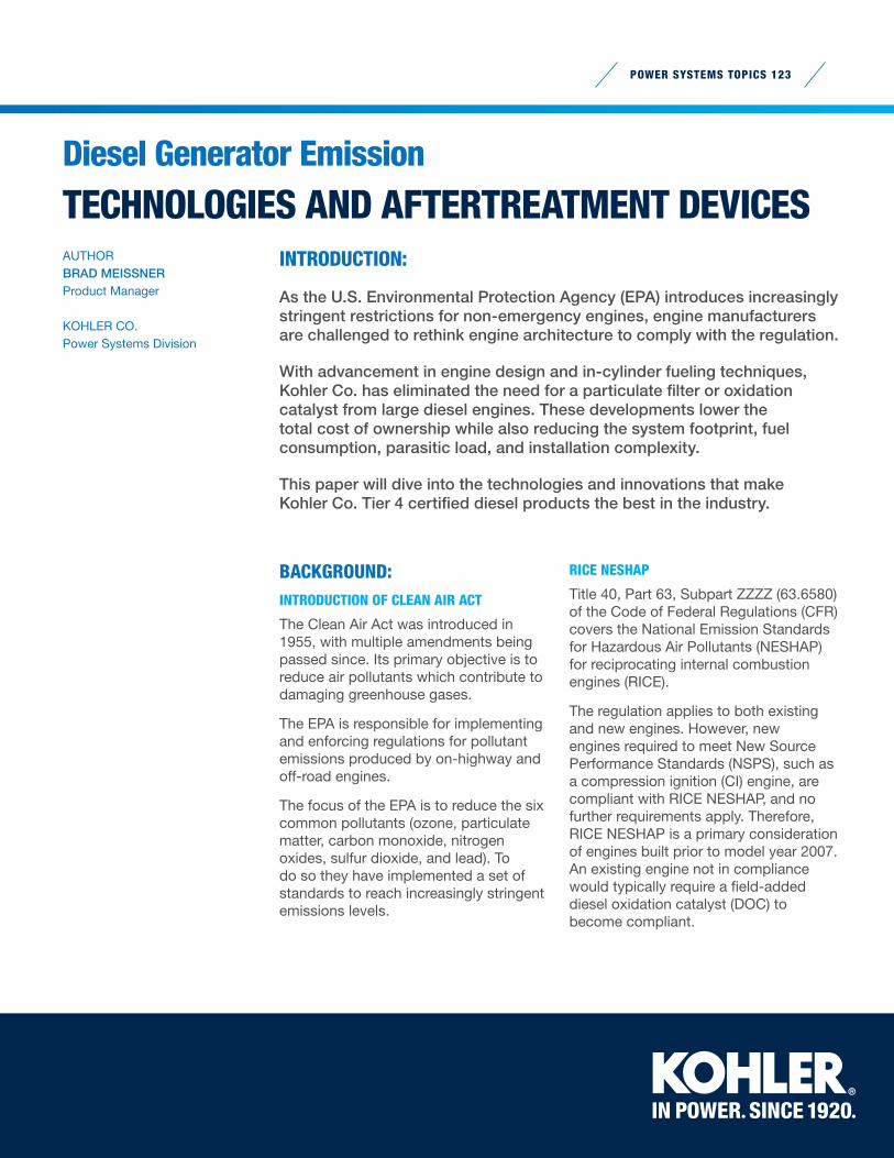
POWER SYSTEMS TOPICS 123 AUTHOR BRAD MEISSNER Product Manager KOHLER CO. Power Systems Division BACKGROUND: INTRODUCTION OF CLEAN AIR ACT The Clean Air Act was introduced in 1955, with multiple amendments being passed since. Its primary objective is to reduce air pollutants which contribute to damaging greenhouse gases. The EPA is responsible for implementing and enforcing regulations for pollutant emissions produced by on-highway and off-road engines. The focus of the EPA is to reduce the six common pollutants (ozone, particulate matter, carbon monoxide, nitrogen oxides, sulfur dioxide, and lead). To do so they have implemented a set of standards to reach increasingly stringent emissions levels. RICE NESHAP Title 40, Part 63, Subpart ZZZZ (63.6580) of the Code of Federal Regulations (CFR) covers the National Emission Standards for Hazardous Air Pollutants (NESHAP) for reciprocating internal combustion engines (RICE). The regulation applies to both existing and new engines. However, new engines required to meet New Source Performance Standards (NSPS), such as a compression ignition (CI) engine, are compliant with RICE NESHAP, and no further requirements apply. Therefore, RICE NESHAP is a primary consideration of engines built prior to model year 2007. An existing engine not in compliance would typically require a field-added diesel oxidation catalyst (DOC) to become compliant. INTRODUCTION: As the U.S. Environmental Protection Agency (EPA) introduces increasingly stringent restrictions for non-emergency engines, engine manufacturers are challenged to rethink engine architecture to comply with the regulation. With advancement in engine design and in-cylinder fueling techniques, Kohler Co. has eliminated the need for a particulate filter or oxidation catalyst from large diesel engines. These developments lower the total cost of ownership while also reducing the system footprint, fuel consumption, parasitic load, and installation complexity. This paper will dive into the technologies and innovations that make Kohler Co. Tier 4 certified diesel products the best in the industry. Diesel Generator Emission TECHNOLOGIES AND AFTERTREATMENT DEVICES
Transcript of TECHNOLOGIES AND AFTERTREATMENT DEVICES
POWER SYSTEMS TOPICS 123
AUTHOR BRAD MEISSNERProduct Manager
KOHLER CO. Power Systems Division
BACKGROUND:INTRODUCTION OF CLEAN AIR ACT
The Clean Air Act was introduced in 1955, with multiple amendments being passed since. Its primary objective is to reduce air pollutants which contribute to damaging greenhouse gases.
The EPA is responsible for implementing and enforcing regulations for pollutant emissions produced by on-highway and off-road engines.
The focus of the EPA is to reduce the six common pollutants (ozone, particulate matter, carbon monoxide, nitrogen oxides, sulfur dioxide, and lead). To do so they have implemented a set of standards to reach increasingly stringent emissions levels.
RICE NESHAP
Title 40, Part 63, Subpart ZZZZ (63.6580) of the Code of Federal Regulations (CFR) covers the National Emission Standards for Hazardous Air Pollutants (NESHAP) for reciprocating internal combustion engines (RICE).
The regulation applies to both existing and new engines. However, new engines required to meet New Source Performance Standards (NSPS), such as a compression ignition (CI) engine, are compliant with RICE NESHAP, and no further requirements apply. Therefore, RICE NESHAP is a primary consideration of engines built prior to model year 2007. An existing engine not in compliance would typically require a field-added diesel oxidation catalyst (DOC) to become compliant.
INTRODUCTION:
As the U.S. Environmental Protection Agency (EPA) introduces increasingly stringent restrictions for non-emergency engines, engine manufacturers are challenged to rethink engine architecture to comply with the regulation.
With advancement in engine design and in-cylinder fueling techniques, Kohler Co. has eliminated the need for a particulate filter or oxidation catalyst from large diesel engines. These developments lower the total cost of ownership while also reducing the system footprint, fuel consumption, parasitic load, and installation complexity.
This paper will dive into the technologies and innovations that make Kohler Co. Tier 4 certified diesel products the best in the industry.
Diesel Generator Emission
TECHNOLOGIES AND AFTERTREATMENT DEVICES
0
0.67
4.00
6.40
0.03 0.10 0.20 0.54
9.20
0
PM [g/kW-hr]
NO
x [g
/kW
-hr]
Stationary Engine Emission Tiers
Tier 1
Tier 2
Tier 3
Tier 4 Interim
Tier 4 Final
POWER SYSTEMS TOPICS 123
NONROAD DIESEL ENGINES
Title 40, Part 1039, of the Code of Federal Regulations (CFR) covers the EPA emission standards for nonroad diesel engines. The standard is applicable to a wide range of construction, agricultural, and industrial equipment.
The EPA classifies these engines as being used on nonhighway equipment meant to be movable; either by being propelled, such as a skid-loader, or by transport, such as a mobile/towable generator. Therefore, diesel generators mounted on either a trailer or a skid meant for transport must abide by nonroad diesel emission regulations, not the stationary emissions discussed later in this paper.
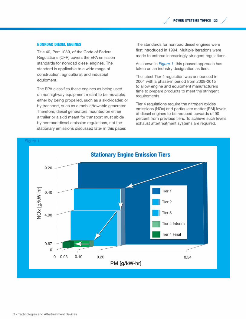
The standards for nonroad diesel engines were first introduced in 1994. Multiple iterations were made to enforce increasingly stringent regulations.
As shown in Figure 1, this phased approach has taken on an industry designation as tiers.
The latest Tier 4 regulation was announced in 2004 with a phase-in period from 2008-2015 to allow engine and equipment manufacturers time to prepare products to meet the stringent requirements.
Tier 4 regulations require the nitrogen oxides emissions (NOx) and particulate matter (PM) levels of diesel engines to be reduced upwards of 90 percent from previous tiers. To achieve such levels exhaust aftertreatment systems are required.
2 / Technologies and Aftertreatment Devices
Figure 1
POWER SYSTEMS TOPICS 123
NSPS for CI Stationary Engines:NON-EMERGENCY AND EMERGENCY GENERATORS
Title 40, Part 60, Subpart IIII of the Code of Federal Regulations (CFR) covers the New Source Performance Standards (NSPS) for stationary reciprocating internal combustion engines (RICE). The standard classifies stationary engines by brake horsepower and use type.
Depending on the classification of the engine, it must be below or at levels of emissions for nitrogen oxides (NOx), particulate matter (PM), carbon monoxide (CO), and nonmethane hydrocarbons (NMHC or simply HC).
The emissions levels of the various categories are based off emissions levels enforced for various types of mobile equipment; therefore, no new engines emissions levels were instituted with the ruling.
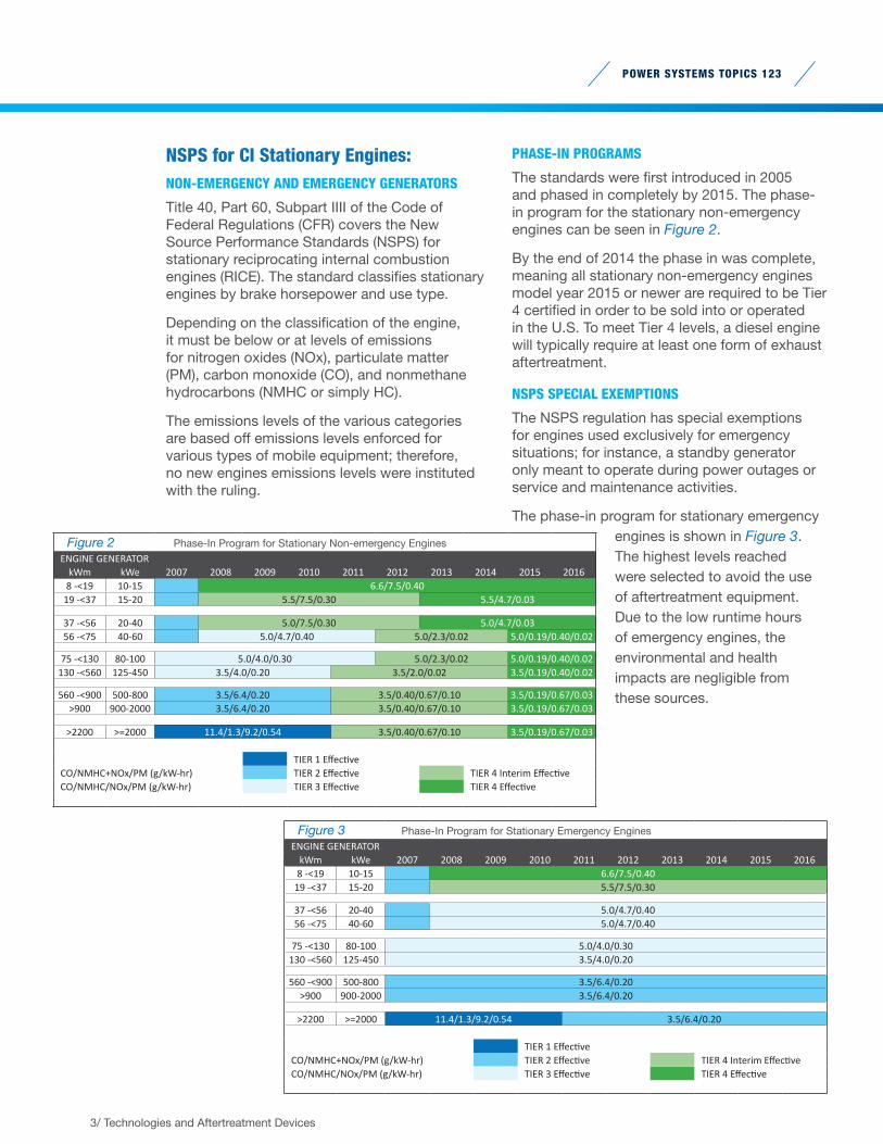
PHASE-IN PROGRAMS
The standards were first introduced in 2005 and phased in completely by 2015. The phase-in program for the stationary non-emergency engines can be seen in Figure 2.
By the end of 2014 the phase in was complete, meaning all stationary non-emergency engines model year 2015 or newer are required to be Tier 4 certified in order to be sold into or operated in the U.S. To meet Tier 4 levels, a diesel engine will typically require at least one form of exhaust aftertreatment.
NSPS SPECIAL EXEMPTIONS
The NSPS regulation has special exemptions for engines used exclusively for emergency situations; for instance, a standby generator only meant to operate during power outages or service and maintenance activities.
The phase-in program for stationary emergency engines is shown in Figure 3. The highest levels reached were selected to avoid the use of aftertreatment equipment. Due to the low runtime hours of emergency engines, the environmental and health impacts are negligible from these sources.
3/ Technologies and Aftertreatment Devices
Figure 2 Phase-In Program for Stationary Non-emergency EnginesENGINE GENERATOR
kWm kWe 2007 2008 2009 2010 2011 2012 2013 2014 2015 20168 -<19 10-15 6.6/7.5/0.40
19 -<37 15-20 5.5/7.5/0.30 5.5/4.7/0.03
37 -<56 20-40 5.0/7.5/0.30 5.0/4.7/0.0356 -<75 40-60 5.0/4.7/0.40 5.0/2.3/0.02 5.0/0.19/0.40/0.02
75 -<130 80-100 5.0/4.0/0.30 5.0/2.3/0.02 5.0/0.19/0.40/0.02130 -<560 125-450 3.5/4.0/0.20 3.5/2.0/0.02 3.5/0.19/0.40/0.02
560 -<900 500-800 3.5/6.4/0.20 3.5/0.40/0.67/0.10 3.5/0.19/0.67/0.03>900 900-2000 3.5/6.4/0.20 3.5/0.40/0.67/0.10 3.5/0.19/0.67/0.03
>2200 >=2000 11.4/1.3/9.2/0.54 3.5/0.40/0.67/0.10 3.5/0.19/0.67/0.03
TIER 1 EffectiveCO/NMHC+NOx/PM (g/kW-hr) TIER 2 Effective TIER 4 Interim EffectiveCO/NMHC/NOx/PM (g/kW-hr) TIER 3 Effective TIER 4 Effective
Figure 3 Phase-In Program for Stationary Emergency EnginesENGINE GENERATOR
kWm kWe 2007 2008 2009 2010 2011 2012 2013 2014 2015 20168 -<19 10-15 6.6/7.5/0.40
19 -<37 15-20 5.5/7.5/0.30
37 -<56 20-40 5.0/4.7/0.4056 -<75 40-60 5.0/4.7/0.40
75 -<130 80-100 5.0/4.0/0.30130 -<560 125-450 3.5/4.0/0.20
560 -<900 500-800 3.5/6.4/0.20>900 900-2000 3.5/6.4/0.20
>2200 >=2000 11.4/1.3/9.2/0.54 3.5/6.4/0.20
TIER 1 EffectiveCO/NMHC+NOx/PM (g/kW-hr) TIER 2 Effective TIER 4 Interim EffectiveCO/NMHC/NOx/PM (g/kW-hr) TIER 3 Effective TIER 4 Effective
POWER SYSTEMS TOPICS 123
MEETING TIER 4 EMISSIONS LEVELS:ADDRESSING NOX AND PM LEVELS
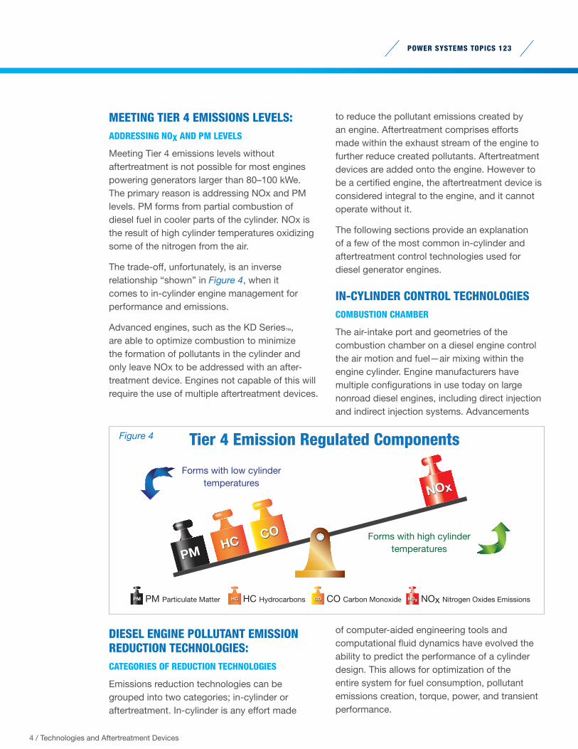
Meeting Tier 4 emissions levels without aftertreatment is not possible for most engines powering generators larger than 80–100 kWe. The primary reason is addressing NOx and PM levels. PM forms from partial combustion of diesel fuel in cooler parts of the cylinder. NOx is the result of high cylinder temperatures oxidizing some of the nitrogen from the air.
The trade-off, unfortunately, is an inverse relationship “shown” in Figure 4, when it comes to in-cylinder engine management for performance and emissions.
Advanced engines, such as the KD Series™, are able to optimize combustion to minimize the formation of pollutants in the cylinder and only leave NOx to be addressed with an after-treatment device. Engines not capable of this will require the use of multiple aftertreatment devices.
DIESEL ENGINE POLLUTANT EMISSION REDUCTION TECHNOLOGIES:CATEGORIES OF REDUCTION TECHNOLOGIES
Emissions reduction technologies can be grouped into two categories; in-cylinder or aftertreatment. In-cylinder is any effort made
to reduce the pollutant emissions created by an engine. Aftertreatment comprises efforts made within the exhaust stream of the engine to further reduce created pollutants. Aftertreatment devices are added onto the engine. However to be a certified engine, the aftertreatment device is considered integral to the engine, and it cannot operate without it.
The following sections provide an explanation of a few of the most common in-cylinder and aftertreatment control technologies used for diesel generator engines.
IN-CYLINDER CONTROL TECHNOLOGIESCOMBUSTION CHAMBER
The air-intake port and geometries of the combustion chamber on a diesel engine control the air motion and fuel—air mixing within the engine cylinder. Engine manufacturers have multiple configurations in use today on large nonroad diesel engines, including direct injection and indirect injection systems. Advancements
of computer-aided engineering tools and computational fluid dynamics have evolved the ability to predict the performance of a cylinder design. This allows for optimization of the entire system for fuel consumption, pollutant emissions creation, torque, power, and transient performance.
Forms with low cylindertemperatures
Forms with high cylindertemperatures
Tier 4 Emission Regulated Components
HCCO
NOx
PM
PM PM Particulate Matter HC HC Hydrocarbons CO CO Carbon Monoxide NOx NOx Nitrogen Oxides Emissions
Figure 4
4 / Technologies and Aftertreatment Devices
HIGH-PRESSURE COMMON RAIL FUEL INJECTION
A fuel system on a common rail diesel engine consists of a low-pressure system (up to 100 PSI) for supplying fuel from the tank to the engine and a high-pressure system (up to 32,000 PSI) for injecting the fuel into the cylinder.
The high-pressure system uses a secondary fuel pump to pressurize the fuel within a “common fuel rail” used to feed the injectors. Increasing the injection pressure allows for finer atomization of the fuel, improved air-fuel mixing, and greater control of injection timing.
Diesel engines with mechanical fuel systems, such as the Mitsubishi used to power Kohler® generators, are limited in their injection pressures and fuel-injection control capability.
ELECTRONIC FUEL INJECTION
Injection rate shaping or fuel mapping are common terms used to describe the capability of a diesel engine with electronic fuel injection. In this system fuel injections are controlled by the engine control unit (ECU) with the use of solenoid-actuated injectors.
The engine is programmed for the ideal time for injection during the combustion cycle, including the ability to make multiple injections within a matter of milliseconds. Utilizing closed-loop feedback controls the engines are also able to adjust the fuel injections to account for transient events, steady state operation, or environmental operating conditions. Electronic fuel injection improves every aspect of engine operation while reducing the creation of air pollutants.
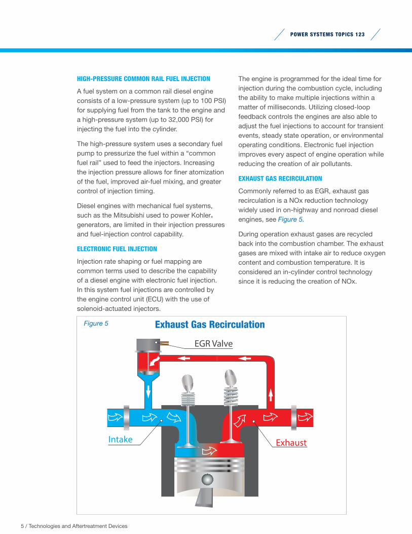
EXHAUST GAS RECIRCULATION
Commonly referred to as EGR, exhaust gas recirculation is a NOx reduction technology widely used in on-highway and nonroad diesel engines, see Figure 5.
During operation exhaust gases are recycled back into the combustion chamber. The exhaust gases are mixed with intake air to reduce oxygen content and combustion temperature. It is considered an in-cylinder control technology since it is reducing the creation of NOx.
POWER SYSTEMS TOPICS 123
5 / Technologies and Aftertreatment Devices
Intake Exhaust
EGR Valve
Exhaust Gas RecirculationFigure 5
POWER SYSTEMS TOPICS 123
6 / Technologies and Aftertreatment Devices
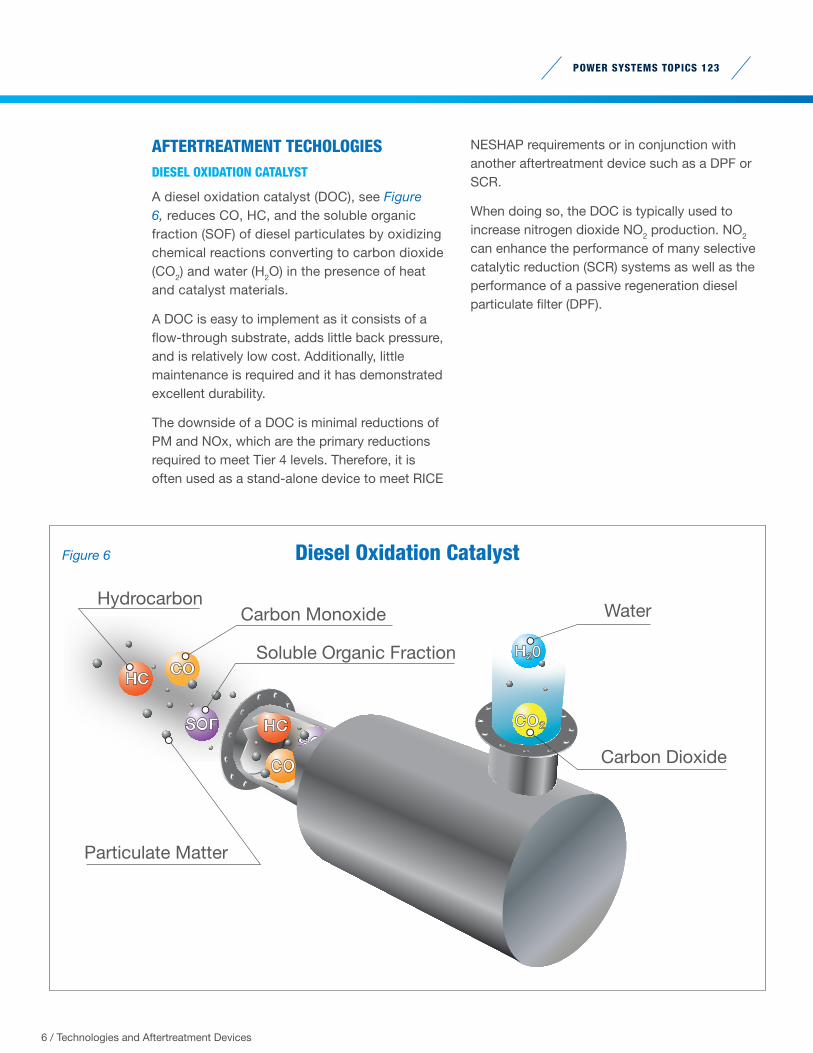
AFTERTREATMENT TECHOLOGIESDIESEL OXIDATION CATALYST
A diesel oxidation catalyst (DOC), see Figure 6, reduces CO, HC, and the soluble organic fraction (SOF) of diesel particulates by oxidizing chemical reactions converting to carbon dioxide (CO2) and water (H2O) in the presence of heat and catalyst materials.
A DOC is easy to implement as it consists of a flow-through substrate, adds little back pressure, and is relatively low cost. Additionally, little maintenance is required and it has demonstrated excellent durability.
The downside of a DOC is minimal reductions of PM and NOx, which are the primary reductions required to meet Tier 4 levels. Therefore, it is often used as a stand-alone device to meet RICE
NESHAP requirements or in conjunction with another aftertreatment device such as a DPF or SCR.
When doing so, the DOC is typically used to increase nitrogen dioxide NO2 production. NO2 can enhance the performance of many selective catalytic reduction (SCR) systems as well as the performance of a passive regeneration diesel particulate filter (DPF).
CO
CO
HC
HC
SOFCO2SOF
HydrocarbonCarbon Monoxide
Soluble Organic Fraction
Particulate Matter
Carbon Dioxide
Water
Diesel Oxidation Catalyst
H20
Figure 6
POWER SYSTEMS TOPICS 123
7 / Technologies and Aftertreatment Devices
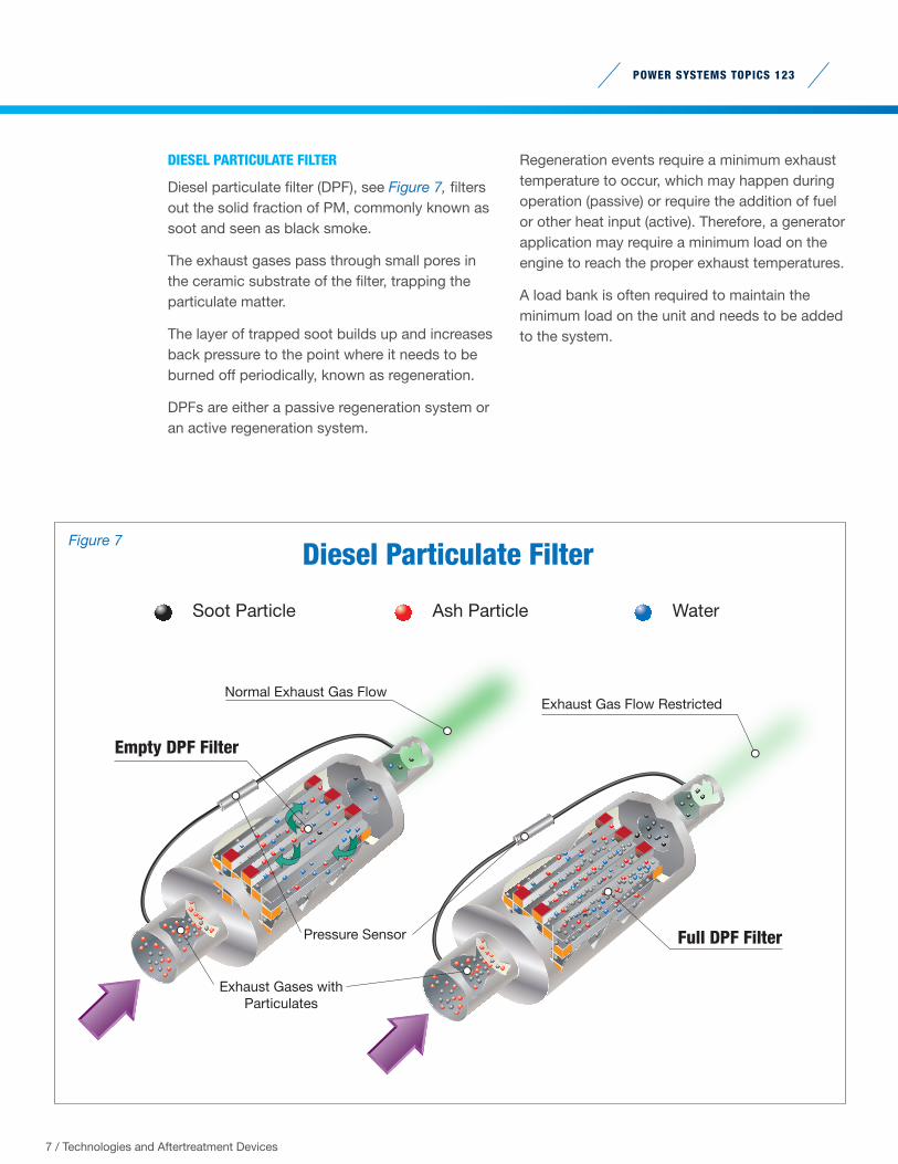
DIESEL PARTICULATE FILTER
Diesel particulate filter (DPF), see Figure 7, filters out the solid fraction of PM, commonly known as soot and seen as black smoke.
The exhaust gases pass through small pores in the ceramic substrate of the filter, trapping the particulate matter.
The layer of trapped soot builds up and increases back pressure to the point where it needs to be burned off periodically, known as regeneration.
DPFs are either a passive regeneration system or an active regeneration system.
Regeneration events require a minimum exhaust temperature to occur, which may happen during operation (passive) or require the addition of fuel or other heat input (active). Therefore, a generator application may require a minimum load on the engine to reach the proper exhaust temperatures.
A load bank is often required to maintain the minimum load on the unit and needs to be added to the system.
Diesel Particulate Filter
Soot Particle Ash Particle Water
Full DPF Filter
Empty DPF Filter
Exhaust Gases with Particulates
Normal Exhaust Gas FlowExhaust Gas Flow Restricted
Pressure Sensor
Figure 7
POWER SYSTEMS TOPICS 123
8 / Technologies and Aftertreatment Devices
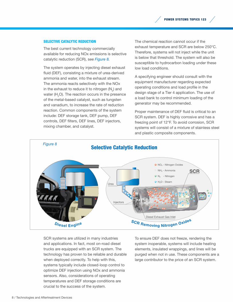
SELECTIVE CATALYTIC REDUCTION
The best current technology commercially available for reducing NOx emissions is selective catalytic reduction (SCR), see Figure 8.
The system operates by injecting diesel exhaust fluid (DEF), consisting a mixture of urea-derived ammonia and water, into the exhaust stream. The ammonia reacts selectively with the NOx in the exhaust to reduce it to nitrogen (N2) and water (H2O). The reaction occurs in the presence of the metal-based catalyst, such as tungsten and vanadium, to increase the rate of reduction reaction. Common components of the system include: DEF storage tank, DEF pump, DEF controls, DEF filters, DEF lines, DEF injectors, mixing chamber, and catalyst.
SCR systems are utilized in many industries and applications. In fact, most on-road diesel trucks are equipped with an SCR system. The technology has proven to be reliable and durable when deployed correctly. To help with this, systems typically include closed-loop control to optimize DEF injection using NOx and ammonia sensors. Also, considerations of operating temperatures and DEF storage conditions are crucial to the success of the system.
The chemical reaction cannot occur if the exhaust temperature and SCR are below 250°C. Therefore, systems will not inject while the unit is below that threshold. The system will also be susceptible to hydrocarbon loading under these low load conditions.
A specifying engineer should consult with the equipment manufacturer regarding expected operating conditions and load profile in the design stage of a Tier 4 application. The use of a load bank to control minimum loading of the generator may be recommended.
Proper maintenance of DEF fluid is critical to an SCR system. DEF is highly corrosive and has a freezing point of 12°F. To avoid corrosion, SCR systems will consist of a mixture of stainless steel and plastic composite components.
To ensure DEF does not freeze, rendering the system inoperable, systems will include heating elements, insulated wrappings, and lines will be purged when not in use. These components are a large contributor to the price of an SCR system.
Diesel Engine
SCR
Urea
Injectors
Diesel Exhaust Gas Inlet
NOx - Nitrogen Oxides
NH3 - Ammonia
N2 - Nitrogen
H2O - Steam
Selective Catalytic Reduction
SCR Removing Nitrogen Oxides
Figure 8
POWER SYSTEMS TOPICS 123
9 / Technologies and Aftertreatment Devices
SELECTIVE CATALYTIC REDUCTION - CONT.
On the other side of the spectrum, DEF fluid is susceptible to degradation at elevated temperatures. When stored at average temperatures at or below 77°F, the shelf life will be in excess of 36 months. It can decrease down to six months under certain conditions. Consult the supplier for specifics on DEF storage requirements before purchasing.
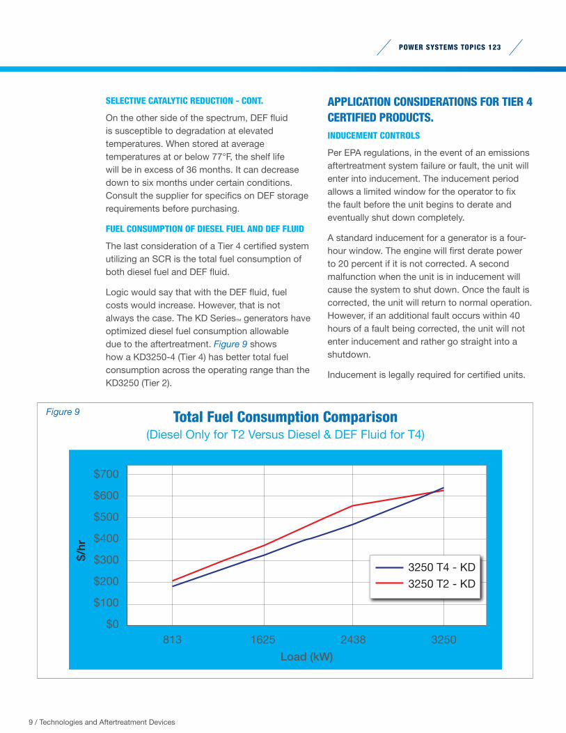
FUEL CONSUMPTION OF DIESEL FUEL AND DEF FLUID
The last consideration of a Tier 4 certified system utilizing an SCR is the total fuel consumption of both diesel fuel and DEF fluid.
Logic would say that with the DEF fluid, fuel costs would increase. However, that is not always the case. The KD Series™ generators have optimized diesel fuel consumption allowable due to the aftertreatment. Figure 9 shows how a KD3250-4 (Tier 4) has better total fuel consumption across the operating range than the KD3250 (Tier 2).
APPLICATION CONSIDERATIONS FOR TIER 4 CERTIFIED PRODUCTS.INDUCEMENT CONTROLS
Per EPA regulations, in the event of an emissions aftertreatment system failure or fault, the unit will enter into inducement. The inducement period allows a limited window for the operator to fix the fault before the unit begins to derate and eventually shut down completely.
A standard inducement for a generator is a four-hour window. The engine will first derate power to 20 percent if it is not corrected. A second malfunction when the unit is in inducement will cause the system to shut down. Once the fault is corrected, the unit will return to normal operation. However, if an additional fault occurs within 40 hours of a fault being corrected, the unit will not enter inducement and rather go straight into a shutdown.
Inducement is legally required for certified units.
$600
$700
$500
$300
$400
$200
$100
$0813 1625 2438
Load (kW)
3250
$/hr
3250 T4 - KD3250 T2 - KD
Total Fuel Consumption Comparison(Diesel Only for T2 Versus Diesel & DEF Fluid for T4)
Figure 9
POWER SYSTEMS TOPICS 123
10 / Technologies and Aftertreatment Devices
MAINTENANCE OF AFTERTREATMENT SYSTEMS
Aftertreatment systems require various levels of service and maintenance. The easiest is a DOC. They are fully contained units that require no maintenance if the engine is operated properly.
An SCR system is the next easiest to maintain. The SCR component, such as the one used on a KD Series™ unit, is typically fully contained and requires no maintenance under normal operating conditions.
The DEF components will, however, require maintenance. DEF filters need periodic replacement and the quality of the DEF fluid needs continuous monitoring and potential replacement if it degrades below usable levels.
A DPF system requires the most maintenance of the three common aftertreatment devices. The primary concern revolves around the cleanliness of the filter. Maintaining proper operating conditions for regeneration is the most effective way of ensuring your generator runs properly. In addition, regular inspections of the filters are needed to identify when cleaning will be required.
Manufacturers will generally require cleaning of the filters at regular run-time or year intervals regardless of cleanliness. To clean a particulate filter, they must be removed from the unit and
sent to an off-site facility. This renders the unit inoperable during this time.
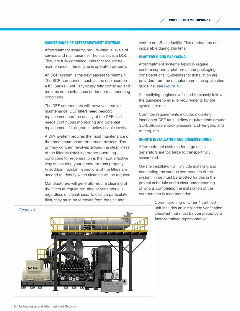
PLAFTFORM AND PACKAGING
Aftertreatment systems typically require custom supports, platforms, and packaging considerations. Guidelines for installation are provided from the manufacturer in an application guideline, see Figure 10.
A specifying engineer will need to closely follow the guideline to ensure requirements for the system are met.
Common requirements include: mounting location of DEF tank, airflow requirements around SCR, allowable back pressure, DEF lengths, and routing, etc.
ON-SITE INSTALLATION AND COMMISSIONING
Aftertreatment systems for large diesel generators are too large to transport fully assembled.
On-site installation will include installing and connecting the various components of the system. Time must be allotted for this in the project schedule and a clear understanding of who is completing the installation of the components is recommended.
Commissioning of a Tier 4 certified unit includes an installation verification checklist that must be completed by a factory-trained representative.
Figure 10
POWER SYSTEMS TOPICS 123
11 / Technologies and Aftertreatment Devices
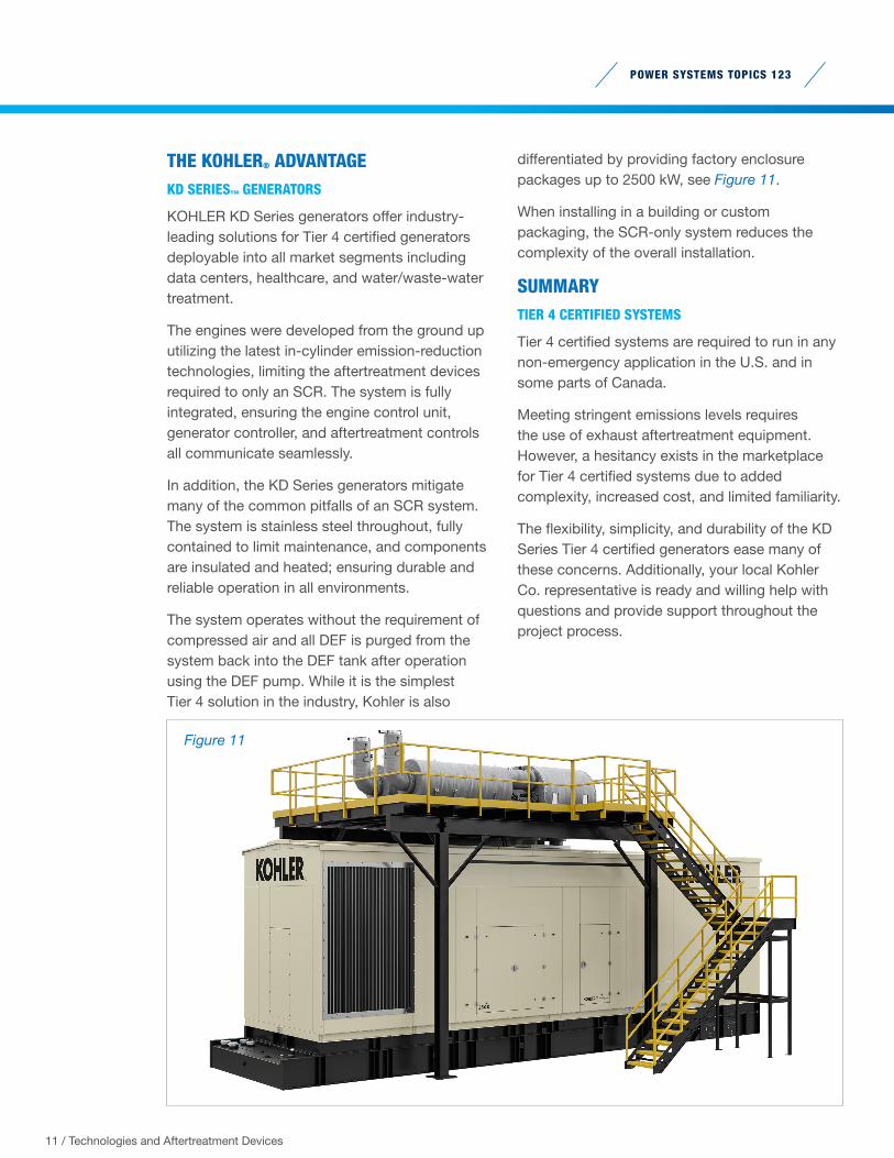
THE KOHLER® ADVANTAGEKD SERIES™ GENERATORS
KOHLER KD Series generators offer industry-leading solutions for Tier 4 certified generators deployable into all market segments including data centers, healthcare, and water/waste-water treatment.
The engines were developed from the ground up utilizing the latest in-cylinder emission-reduction technologies, limiting the aftertreatment devices required to only an SCR. The system is fully integrated, ensuring the engine control unit, generator controller, and aftertreatment controls all communicate seamlessly.
In addition, the KD Series generators mitigate many of the common pitfalls of an SCR system. The system is stainless steel throughout, fully contained to limit maintenance, and components are insulated and heated; ensuring durable and reliable operation in all environments.
The system operates without the requirement of compressed air and all DEF is purged from the system back into the DEF tank after operation using the DEF pump. While it is the simplest Tier 4 solution in the industry, Kohler is also
differentiated by providing factory enclosure packages up to 2500 kW, see Figure 11.
When installing in a building or custom packaging, the SCR-only system reduces the complexity of the overall installation.
SUMMARYTIER 4 CERTIFIED SYSTEMS
Tier 4 certified systems are required to run in any non-emergency application in the U.S. and in some parts of Canada.
Meeting stringent emissions levels requires the use of exhaust aftertreatment equipment. However, a hesitancy exists in the marketplace for Tier 4 certified systems due to added complexity, increased cost, and limited familiarity.
The flexibility, simplicity, and durability of the KD Series Tier 4 certified generators ease many of these concerns. Additionally, your local Kohler Co. representative is ready and willing help with questions and provide support throughout the project process.
Figure 11
POWER SYSTEMS TOPICS 123
ABOUT THE AUTHOR
Brad Meissner currently works as a Product Manager with responsibility
for diesel generators greater than 700 kW at Kohler Co.
Degreed in both mechanical engineering and engineering management,
he has spent more than seven years in the power generation industry.
His career started in engineering developing alternators, diesel fuel
tanks, enclosures, and generator sets. For the last three years he has
worked as part of the product management team at Kohler Co. His
specialties include codes and standards, diesel emissions, generator
set packaging, and mechanical systems.
A global force in power solutions since 1920, Kohler Co. is
committed to reliable, intelligent products; purposeful engineering:
and responsive after-sales support. Kohler Co. is among the world’s
largest manufacturers of industrial generators. The company has 100
years’ experience in industrial power and benefits from global R&D,
manufacturing, sales, service, and distribution integration.
12 / Technologies and Aftertreatment Devices
KOHLER POWER.COMPrinted in U.S.A. G26-34 KPS 123 08/20 © 2020 by Kohler Co.