Colorful Spectrum Analyser
25
Colorful Spectrum Analyser Final Project Report December 11th, 2009 E155 Chris Ferguson and Matthew Keeter Abstract One common ‘extra’ seen on stereo systems is the graphical equalizer: columns of lights that move up and down based on the frequency content of the music. This final project is a similar type of display. The system takes in the audio output of an iPod, and displays the frequency content of eight different frequency on an 8×8 grid of colored LEDs. It uses eight bandpass filters, which are implemented on the FPGA as 256-tap digital FIR filters. The bands range from 0 to 4000 Hz, and are geometrically spaced such that each band is approximately 1.7× the size of the previous band, which allows for greater resolution at lower frequencies. The resulting output is smoothed to make it visually appealing, and is clearly visible even in a well-lit room. 1
Transcript of Colorful Spectrum Analyser

Colorful Spectrum Analyser
Final Project ReportDecember 11th, 2009
E155Chris Ferguson and Matthew Keeter
Abstract
One common ‘extra’ seen on stereo systems is the graphical equalizer: columns of lights that moveup and down based on the frequency content of the music. This final project is a similar type ofdisplay. The system takes in the audio output of an iPod, and displays the frequency content ofeight different frequency on an 8×8 grid of colored LEDs. It uses eight bandpass filters, which areimplemented on the FPGA as 256-tap digital FIR filters. The bands range from 0 to 4000 Hz, andare geometrically spaced such that each band is approximately 1.7× the size of the previous band,which allows for greater resolution at lower frequencies. The resulting output is smoothed to makeit visually appealing, and is clearly visible even in a well-lit room.
1

Introduction
The goal of our MicroP’s project is to create a device that can take in an audio signal from a sourcesuch as an iPod, and have a colorful illuminated display that represents the frequency content of theincoming music. The information is conveyed in a set of columns, which light up with the heightof illumination determined by the magnitude of content in that frequency band. This project wasdesigned to operate on a limited frequency range, with 8 different frequency bands displayed. Thisdisplay is reminiscent of the “graphic equalizers that are often seen on stereo systems. The projectwill also allow for an application of the signal processing techniques developed in the AdvancedSystem Engineering class (E101), with the use of digital filters to determine the frequency content.
Project Overview
In order to display the frequency content of the incoming signal, several high-level tasked need tobe accompished. The incoming audio, in the form of a voltage signal, needs to be sanitized in theanalog domain, and then converted into digital data. This digital signal then needs to be processedto determine the content in each of the desired frequency bands. Finally, this information is used tocontrol a column-based output display. This gives the four main sections of the project: the analogsignal conditioning, the PIC, the FPGA, and the output LEDs. Data flows linearly through eachstage, as seen in figure 1. Input audio signals enter the system at the analog signal conditioningcircuitry, and the LEDs light up as the output to the viewers. If a headphone splitter is used atthe audio source, then the audio can be listened too as well as viewed on the system display.
Low-pass filter
Boost and scale
A/D conversion
Two’s Complement conversion
FIR bandpass
filters
Input manager
Output manager
clk
FPGA reset
Filter coefficients (precalculated)
LEDs
PIC FPGA
PIC reset
Voltage follower
Audio in
Analog signal conditioning
Figure 1: Data flow through the system
In designing this project, the two most important decisions were what frequency ranges to usefor the analysis, and what method to use to calculate the signal content. The maximum frequencyexamined was set at 4000 Hz, which is high enough to capture at least the first harmonic of mostmusical soundsfor example, the highest note on a piano, C8, just above 4000 Hz [1]. The methodof analysis chosen was one that would be the most straightforward to implement on our availablehardware: a series of digital Finite Impulse Response (FIR) bandpass filters spread out from 0 to4kHz. The bands were spaced logarithmically, with the lower bands being smaller, to better reflectthe distribution of musical content.
The entire system was implemented around a central breadboard. The LED array and sig-nal conditioning circuitry were both implemented on daughterboards that plugged into the main
2

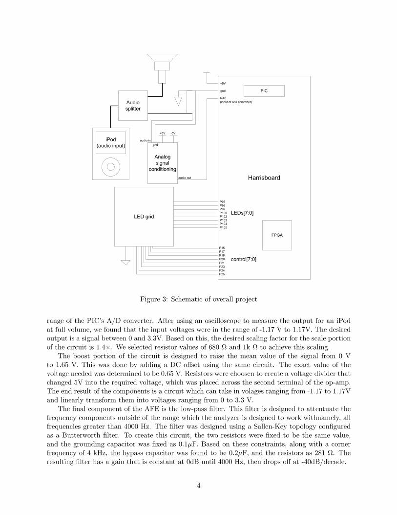
breadboard, to make the system modular. The overall system requires power for the Harrisboard(3.3 V minimum, usually 5 V), a ground, and power for the op-amps ( +5V and -5V). The initialsignal conditioning requires power inputs of +5V, -5V, ground, and a 1/8 inch audio plug for signalinput. It puts out a single output to a pin on the PIC. The LED output display has 8 data inputsto determine the height of a column, and 8 control inputs to determine which column is active, aswell as a common ground. A schematic for the entire project can be seen in Figure 3.
Figure 2: Frequency Analyzer in operation
Analog Front End
The analog front end (AFE) consists of a series of conditioning circuits to prepare the music forsampling by the A/D converter. The three components of this system are a voltage follower (buffer),a booster/scaler, and a low-pass filter. These can be seen in Figure 4. Each stage uses a 741-seriesop-amp, which receive power at +5 and 5 V. When a stereo audio input is used, the left and rightchannels are shorted together by the 1/4 audio jack which was used to interface with the audiocable. This combined signal is the input voltage, while the signal’s ground was tied to the commonground on the breadboard.
The voltage follower circuit, at the top of Figure 4, is fairly simple, consisting of just the op-amp and wire, with no other components. The purpose of the voltage follower is to isolate theaudio source’s output from the rest of the conditioning circuitryfor example, to prevent excessivecurrent draw on the device. While not initially anticipated, the need for this circuit was determinedexperimentally when attaching an iPod directly to the rest of the AFE led to a loss of signal. Oncethe voltage follower was included in the circuit, all of the components performed as expected.
The booster/scaler circuit is the middle block in Figure 4. This circuit’s purpose is to take theinput voltages, which cover a range of positive and negative values, and then shift and scale themto maximally fill the range from 0 to 3.3 V. This final range was choosen because it is the input
3
Harrisboard
Analog signal
conditioning
gnd
+5V
+5V -5V
gndaudio in
RA0(input of A/D converter)
audio out
P97P98P99P100P102P103P104P105
LEDs[7:0]
P15P17P18P20P21P23P24P25
control[7:0]
LED grid
iPod(audio input)
PIC
FPGA
Audio splitter
Figure 3: Schematic of overall project
range of the PIC’s A/D converter. After using an oscilloscope to measure the output for an iPodat full volume, we found that the input voltages were in the range of -1.17 V to 1.17V. The desiredoutput is a signal between 0 and 3.3V. Based on this, the desired scaling factor for the scale portionof the circuit is 1.4×. We selected resistor values of 680 Ω and 1k Ω to achieve this scaling.
The boost portion of the circuit is designed to raise the mean value of the signal from 0 Vto 1.65 V. This was done by adding a DC offset using the same circuit. The exact value of thevoltage needed was determined to be 0.65 V. Resistors were choosen to create a voltage divider thatchanged 5V into the required voltage, which was placed across the second terminal of the op-amp.The end result of the components is a circuit which can take in volages ranging from -1.17 to 1.17Vand linearly transform them into voltages ranging from 0 to 3.3 V.
The final component of the AFE is the low-pass filter. This filter is designed to attentuate thefrequency components outside of the range which the analyzer is designed to work withnamely, allfrequencies greater than 4000 Hz. The filter was designed using a Sallen-Key topology configuredas a Butterworth filter. To create this circuit, the two resistors were fixed to be the same value,and the grounding capacitor was fixed as 0.1µF. Based on these constraints, along with a cornerfrequency of 4 kHz, the bypass capacitor was found to be 0.2µF, and the resistors as 281 Ω. Theresulting filter has a gain that is constant at 0dB until 4000 Hz, then drops off at -40dB/decade.
4

-
+
P-
P+
out
1 kΩ680 Ω
-
+
P-
P+
out
-
+
P-
P+
out
1 kΩ
150 Ω
281 Ω
281 Ω
0.1 µF
0.2 µF
Analog signal in
Filtered signal out (to RA0)
Voltage follower
Scale and boost
Low-pass filter
All op-amps are 741 typeAll resistor tolerances are 5%
indicates a connection to +5 V indicates a connection to -5 V
+5V
Figure 4: Analog Front End Schematic
PIC
In this project, the PIC is used to sample analog data and pass the results to the FPGA. Since wechose to look at frequencies up to 4 kHz, the PIC must sample at above 8 kHz to avoid aliasing.We implemented code that causes the PIC to sample at approximately 9.6 kHz; this means thatthere is a Nyquist frequency of 4.8 kHz, and the lowest signal that could fold or alias into thebands of interest is 5.6 kHz. Thus, the analog low-pass filter has already been attenuating potentialhigh-frequency noise for 1600 Hz before it could alias into the bands of interest. The PICs A/Dconverter takes in the output of the signal conditioning circuitry, and converts it into an 8-bitbinary number, with 0 indicating 0V and 255 indicating 3.3V.
5

The PIC code runs by first initializing the A/D converter and Timer 0, with interrupts. Thetimer is set to trigger an interrupt every 104 µs, corresponding to a frequency of 9.6 kHz. Wheneverthe interrupt for the A/D converter goes high, the system first takes this 8-bit value and subtracts128 from it, converting from a 0-255 scale to a two’s-complement value between -128 and 127, whichis expected by the FPGA. Then the PIC sets the 8 data bits to their desired values on the busconnecting the PIC to the FPGA. Then the PIC sets a separate “new data” bit high, signaling tothe FPGA that the next data sample is ready to be recorded. The A/D converter is reinitializedto allow it to prepare for conversion. The PIC then continues to wait until the interrupt for Timer0 goes off, indicating that the PIC should begin sampling the data again. It is at this point thatthe “new data” bit is reset back to 0, allowing the FPGA to detect when the next new set of datacomes in. This process continues, allowing the PIC to sample the data at 9.6 kHz and send thisdata to the FPGA consistently. The C code which runs on the PIC can be found in Appendix A.
By running the PIC in this manner, we make it easier for the FPGA to avoid any issues withmetastable data. By using this method, the 8 data bits have all resolved before the FPGA triesto read them, as the FPGA does not attempt to record the data until it has received a separatesignal which is sent after the data has long since resolved. If, on the other hand, the “new data”bit is changing when the FPGA tries to read it, one of two things will happen: either the FPGAwill read it as a 1 and take in the already-resolved new data, or it will read it as a 0 and wait anextra cycle before reading a 1 and recording the data. As the data bits remain unchanging for asignificant amount of time after the “new data” bit goes high, this slight delay will not cause aproblem.
FPGA
The FPGA performs three main roles: Storing the sampled data, applying bandpass filters, andcontrolling the LED array. The data storage system runs independently of the other two systems;the other two share certain timing signals. The overall flow of data through the FPGA can be seenin Figure 5
clk
new data indicatordata in [7:0]
control[7:0]
thermometer decoder
thermometer
current_col[2:0]
col_clk
mult_stage[4:0]
mult_clk
LEDs[7:0]
FIR bandpass filterFIR_multiplexer
one-hot decodercol_select
output smoothingout_ram
Input managershift_reg256
Timing controlclock_slower
Figure 5: Data flow through FPGA
The FPGA’s first function is to store data from the PIC. This is done through the asynchronousinterface described in the section above. When the “new data” bit goes from low to high, the FPGAadds the 8 bits of incoming data into a shift register at the next clock tick. This shift register is
6

2048 bits long, equivalent to 256 time-history values, each of which is 8 bits.The next stage of data processing is applying the bandpass filters. This is synchronized such
that only the bandpass filter for the active column is applied. We chose to use digital FIR bandpassfilters [2]. To calculate the filtered output, the time history is multiplied with a pre-calculated setof coefficients, performing a calculation of the form
y = x0c0 + x1c1 + x2c2 + x3c3 + ...xncn
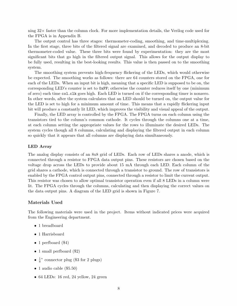
where the coefficients c1...n are pre-calculated in Matlab using the code in Appendix C. These valuesare 8-bit integers, created using scaled versions of the ”true” digital filter coefficients. These 2048coefficients (256 coefficients at 8 bits each) were stored in one of the FPGA’s block RAMs as aROM created in CoreGen. The coefficients correspond to bandpass filters for the following bands:0-41Hz, 41-110Hz, 110-228Hz, 228-428Hz, 428-768Hz, 768-1346Hz, 1346-2329Hz, and 2329-4000Hz.A plot of the bandpass filters used can be found in Figure 6.
100
101
102
103
104
0
100
200
300
400
500
600
Frequency (Hz)
Ga
in
Figure 6: Plot of Bandpass FIR Filters (y axis is arbitrary units)
In order to create a 256-tap filter, the filter hardware (multipliers and adders) was time multi-plexed. We created one module that behaved as an 8-tap filter, then used this filter 32 times overthe course of the calculation, summing the results. Each calculation, new coefficients were readout of the block ram, and the sum was stored in a cumulative register. This time-multiplexing wasnecessary because there are not enough slices on the FPGA to create enough multipliers for thislarge of a digital filter. Instead, we chose to use the dedicated multipliers; however, this led to asecond problem: the FPGA’s dedicated multipliers share output circuitry with the block RAM.This limited us to eight multipliers, since we wanted to store the very large coefficients sets inblock RAM for efficiency. The time multiplexing system uses the counter mult stage[4:0], whichcounts from 0 to 31 every time the current column increments by one (where the current columnrepresents the filter band currently being calculated and displayed). The FIR multiplexer blockuses mult stage[4:0] to select appropriate sections of the time history and coefficient ROM tosend into the 8-tap filter block. This process is synchronized with mult clk, which is a clock run-
7
ning 32× faster than the column clock. For more implementation details, the Verilog code used forthe FPGA is in Appendix B.
The output control has three stages: thermometer-coding, smoothing, and time-multiplexing.In the first stage, three bits of the filtered signal are examined, and decoded to produce an 8-bitthermometer-coded value. These three bits were found by experimentation: they are the mostsignificant bits that go high in the filtered output signal. This allows for the output display tobe fully used, resulting in the best-looking results. This value is then passed on to the smoothingsystem.
The smoothing system prevents high-frequency flickering of the LEDs, which would otherwisebe expected. The smoothing works as follows: there are 64 counters stored on the FPGA, one foreach of the LEDs. When an input bit is high, meaning that a specific LED is supposed to be on, thecorresponding LED’s counter is set to 0xFF; otherwise the counter reduces itself by one (minimumof zero) each time col clk goes high. Each LED is turned on if the corresponding timer is nonzero.In other words, after the system calculates that an LED should be turned on, the output value forthe LED is set to high for a minimum amount of time. This means that a rapidly flickering inputbit will produce a constantly lit LED, which improves the visibility and visual appeal of the output.
Finally, the LED array is controlled by the FPGA. The FPGA turns on each column using thetransistors tied to the column’s common cathode. It cycles through the columns one at a time,at each column setting the appropriate values for the rows to illuminate the desired LEDs. Thesystem cycles though all 8 columns, calculating and displaying the filtered output in each columnso quickly that it appears that all columns are displaying data simultaneously.
LED Array
The analog display consists of an 8x8 grid of LEDs. Each row of LEDs shares a anode, which isconnected through a resistor to FPGA data output pins. These resistors are chosen based on thevoltage drop across the LEDs to provide about 15 mA through each LED. Each column of thegrid shares a cathode, which is connected through a transistor to ground. The row of transistors isenabled by the FPGA control output pins, connected through a resistor to limit the current output.This resistor was chosen to allow optimal transistor operation even if all 8 LEDs in a column werelit. The FPGA cycles through the columns, calculating and then displaying the correct values onthe data output pins. A diagram of the LED grid is shown in Figure 7.
Materials Used
The following materials were used in the project. Items without indicated prices were acquiredfrom the Engineering department.
• 1 breadboard
• 1 Harrisboard
• 1 perfboard ($4)
• 1 small perfboard ($2)
• 18” connector plug ($3 for 2 plugs)
• 1 audio cable ($5.50)
• 64 LEDs: 16 red, 24 yellow, 24 green
8

100 ohms
100 ohms
82 ohms
82 ohms
82 ohms
82 ohms
82 ohms
82 ohms
All 270 ohms
P15P17P18P20P21P23P24P25
P97
P104
P103
P102
P100
P99
P98
P105
control[7:0]
LEDs[7:0]
gnd
Red
Red
Yellow
Yellow
Yellow
Yellow
Green
Green
represents two unconnected wires
Note:
Row Color:
2N3904 transistors
Figure 7: LED grid implementation
• 8 NPN transistors (2N3904)
• 3 741-type op-amps
• Various resistors
• Various capacitors
• Headphone splitter
• Speakers
Results
The project was successful: an iPod could be plugged into the analog jack, and the LEDs lit up insynchrony with the song. The system was also tested using an audio file constructed in Audacity,which consisted of a series of pure sine waves at the center of each band played in succession.With each tone, the corresponding band lit up to the top. There was a small amount of spectralleakage noticeable in the lowest band. This is because this band occupies less than 1% of thetotal frequency range, so even with a 256-tap filter the cut-offs are not ideal (see Figure 6 for thefrequency responses). The system also performed very well when given a regular song as input. Bywatching the LED output, it was possible to detect beats in the music. The 41-110Hz and 110-228Hz bands both exhibited large peaks following the primary ”beat” of the music, to be expected
9
based on the low frequency instruments usually used to generate the sounds. Even with the 8×time multiplexing on the output display, the LEDs could be seen in a well-lit room; however, theeffect was observed to be much more impressive in the dark.
References
[1]“Piano key frequncies.” Wikipedia 11 Dec. 2009. <http://en.wikipedia.org/wiki/Piano key frequencies>
[2] Bright, Anthony. Class Lecture. Advanced Systems Engineering. Harvey Mudd College, Clare-mont CA. 14 Oct 2009.
10
Appendix A: C code
/*A_D_convert.cChris Ferguson & Matt [email protected]@hmc.edu
Code to take in Analog sound input and convert it to8-bit digital signal at a specific sampling rate,sending the converted values through PORTCto an FPGA listening for a "new data" bit on PORTE[0].
*/
#include <p18f452.h>
void main(void);void isr(void);
//goes to actual interrupt program upon interrupt#pragma code high_vector=0x08void high_interrupt(void)
_asmGOTO isr
_endasm
//creates the main program to setup everything and loop#pragma codevoid main(void)
//We want global and peripheral interrupts onINTCONbits.GIE=1;INTCONbits.PEIE=1;PIE1bits.ADIE=1;//Now turn on Timer 0 interruptINTCONbits.TMR0IE=1;
//Configurations/*Timer0 or T0CON7:TMR0On = 16:T08BIT = 0 (16-bit mode)5:T0CS = 0 (internal clock)4:T0SE = 0 (doesn’t matter)3:PSA = 1 (no prescaler!)2: = 0
11

1: = 0 (don’t care)0: = 0*/T0CON=0b10001000;
//T0CON=0b10000111; Used for slow register updating/* A/D Converter: ADCON07-6:ADCS = 10 set A/D clock5-3:CHS = 000 read channel A[0]2: Go/~Done = 0 Don’t start yet1: = 0 unimplemented0:ADON = 1 turn on converter*/ADCON0=0b10000001;
/*A/D Converter: ADCON17:ADFM = 0 left-justify6:ADCS = 0 sets A/D clock5-4: = 00 unimplemented3-0: = 1110 sets only A[0] as analog*/ADCON1=0b00001110;
//Setupt inputs/outputsTRISA = 0xFF; //All inputs
TRISC = 0; //All of these are outputs of PICTRISE = 0; //
PORTC = 0;PORTE = 0;
//set timer valueTMR0H=0xFe;TMR0L=0x0c;
//MAIN CODE LOOP. Put intereresting stuff here if we want to do any of itwhile(1) ;
//Interrupt code#pragma interrupt isrvoid isr(void)
12

if(INTCONbits.TMR0IF)INTCONbits.TMR0IF = 0; //resetADCON0bits.GO=1; //Start A/D converterPORTE=0; // valid bit lowTMR0H=0xfe; // reset timerTMR0L=0x0c;
else if (PIR1bits.ADIF)
PIR1bits.ADIF=0; //resetPORTC=ADRESH; //Get DataPORTC=PORTC - 128; //Convert to two’s complementPORTE=0x01; //valid bit high
13

Appendix B: Verilog code
////////////////////////////////////////////////////////////////////////////////// Matt Keeter & Chris Ferguson// [email protected]//// spectrum_v3: performs bandpass filtering on an input signal,// displaying the output on a grid of LEDs//////////////////////////////////////////////////////////////////////////////////
module spectrum_v3(input initb,input clk,input [7:0] data_in,input new_data,input music_mode,output [7:0] LEDs,output [7:0] control
);
wire reset;assign reset = ~initb;
// we’re using a 256-tap filter, with 8 bits of data for each tapwire [2047:0] time_data;
// this keeps track of the current columnwire [2:0] current_col;
// this is the output of the FIR filterwire [23:0] filtered_time;
// these are various wires used to time-multiplex the multiplierswire mult_clk;wire col_clk;wire [4:0] mult_stage;
// this block slows down the clock in various amounts, to set up// the output multiplexing and the multiplier multiplexingclock_slower timing_control(clk, reset, current_col,
col_clk, mult_stage, mult_clk);
// one-hot decoder of current_colcol_select column_control(current_col, control);
// manage the asynchronous input and store time data
14

shift_reg256 time_history(clk, reset, data_in, new_data, time_data);
// the actual FIR filterFIR_multiplexer bandpass(time_data, current_col, mult_stage,
mult_clk, reset, filtered_time);
// thermometer decodingwire [7:0] therm;thermometer display_control(filtered_time, current_col,
music_mode, therm);
// output system that smooths out high-frequency flickeringout_ram outram(col_clk, reset, therm, current_col, LEDs);
endmodule
////////////////////////////////////////////////////////////////////////////////// Matt Keeter// [email protected]// Chris Ferguson//// module that takes in a fast clk (20 MHz), and outputs a slower counter// that cycles from 0 to 7 and then overflows//// Also outputs mult_stage, which cycles from 0 to 3 with every counter tick,// and mult_clk, which is a clock that switches with every tick of mult_stage//////////////////////////////////////////////////////////////////////////////////
module clock_slower(input clk, reset,output [2:0] current_col,output col_clk,output [4:0] mult_stage,output mult_clk);
// timer constantly counts upreg [13:0] timer;
always @(posedge clk, posedge reset)begin
if (reset) begintimer = 14’b0;
endelse begin
timer = timer + 1;
15

endend
assign current_col = timer[13:11];assign col_clk = ~timer[10];assign mult_stage = timer[10:6];assign mult_clk = timer[5];
endmodule
////////////////////////////////////////////////////////////////////////////////// Matt Keeter// [email protected]// Chris Ferguson//// module that multiplexes an FIR filter block to increase the number of// coefficients. The FIR block is intended to use 8 coefficients; this// module multiplexes it 32 times to make a 256-tap filter//////////////////////////////////////////////////////////////////////////////////module FIR_multiplexer( input [2047:0] time_history,
input [2:0] current_col,input [4:0] mult_stage,input mult_clk, reset,output [23:0] y_abs);
reg [63:0] current_x;wire[63:0] current_c;reg signed [23:0] y;
// select the correct section of time-history to put into the filter// (this part should synthesize to a mux)always @(*)begin
case(mult_stage)0: current_x = time_history[63:0];1: current_x = time_history[127:64];2: current_x = time_history[191:128];3: current_x = time_history[255:192];4: current_x = time_history[319:256];5: current_x = time_history[383:320];6: current_x = time_history[447:384];7: current_x = time_history[511:448];8: current_x = time_history[575:512];9: current_x = time_history[639:576];10: current_x = time_history[703:640];11: current_x = time_history[767:704];12: current_x = time_history[831:768];
16

13: current_x = time_history[895:832];14: current_x = time_history[959:896];15: current_x = time_history[1023:960];16: current_x = time_history[1087:1024];17: current_x = time_history[1151:1088];18: current_x = time_history[1215:1152];19: current_x = time_history[1279:1216];20: current_x = time_history[1343:1280];21: current_x = time_history[1407:1344];22: current_x = time_history[1471:1408];23: current_x = time_history[1535:1472];24: current_x = time_history[1599:1536];25: current_x = time_history[1663:1600];26: current_x = time_history[1727:1664];27: current_x = time_history[1791:1728];28: current_x = time_history[1855:1792];29: current_x = time_history[1919:1856];30: current_x = time_history[1983:1920];31: current_x = time_history[2047:1984];default: current_x = 128’b0;
endcaseend
// block ROM generated using coregen stores the coefficientscoeffmem256 memory(mult_clk,current_col, mult_stage, current_c);
wire signed [18:0] filter_output;
FIRfilter8 filter(current_x, current_c, filter_output);
// register to store sum of multiple filter iterationsalways @(posedge mult_clk, posedge reset) begin
if (reset) beginy = 24’b0;
endelse if (mult_stage == 3’b0) begin
y = filter_output;endelse begin
y = y + filter_output;end
end
// take the absolute value of y to prevent some output flickeringassign y_abs = y[23] ? ~y[23:0]+23’b1 : y[23:0];
endmodule
17

////////////////////////////////////////////////////////////////////////////////// Matt Keeter// [email protected]// Chris Ferguson// modified 11/21/09//// FIRfilter// Takes in a set of 8-bit input values, and a set of 8-bit coefficients,// then multiplies each input by its coefficient and sums the results//////////////////////////////////////////////////////////////////////////////////module FIRfilter8(input [63:0] x,
input [63:0] c,output signed [18:0] y);
wire signed [15:0] xc1, xc2, xc3, xc4, xc5, xc6, xc7, xc8;mult mult1(x[7:0], c[7:0], xc1);mult mult2(x[15:8], c[15:8], xc2);mult mult3(x[23:16], c[23:16], xc3);mult mult4(x[31:24], c[31:24], xc4);mult mult5(x[39:32], c[39:32], xc5);mult mult6(x[47:40], c[47:40], xc6);mult mult7(x[55:48], c[55:48], xc7);mult mult8(x[63:56], c[63:56], xc8);assign y = xc1+xc2+xc3+xc4+xc5+xc6+xc7+xc8;
endmodule
////////////////////////////////////////////////////////////////////////////////// Matt Keeter// Chris Ferguson// [email protected]// modified 11/22/09//// shift_reg256// Module to take act as a shift register for the 256 most// recent inputs//////////////////////////////////////////////////////////////////////////////////module shift_reg256(
input clk,input reset,input [7:0] data_in,input new_data,output reg [2047:0] stored_data
);reg take_new; //wire to only take data once per new input
always@ (posedge clk, posedge reset)begin
18

if(reset)begin
take_new=1’b0;stored_data=2048’b0;
endelse
begin//Only update if you have new data and haven’t updated yetif (new_data && take_new)
beginstored_data= stored_data[2040:0], data_in;take_new=1’b0;
end//once new data goes low, allow data to be retaken
else if (!new_data && !take_new)begin
take_new = 1’b1;end
endend
endmodule
////////////////////////////////////////////////////////////////////////////////// Matt Keeter// [email protected]// Chris Ferguson// modified 11/21/09*//// col_select// Module to take in a 3 bit counter and convert it to a 1-hot output//////////////////////////////////////////////////////////////////////////////////module col_select(
input [2:0] number,output reg [7:0] columns
);
always @(number)begin
case (number)0: columns=8’b00000001;1: columns=8’b00000010;2: columns=8’b00000100;3: columns=8’b00001000;4: columns=8’b00010000;5: columns=8’b00100000;6: columns=8’b01000000;
19

7: columns=8’b10000000;default: columns=8’b00000000;
endcaseend
endmodule
////////////////////////////////////////////////////////////////////////////////// Matt Keeter// [email protected]// Chris Ferguson// modified 12/5/09//// thermometer// module to take in a input value and output an 8-bit thermometer style display//////////////////////////////////////////////////////////////////////////////////module thermometer(
input [23:0] x,input [2:0] col_select,input music_mode,output reg [7:0] therm
);
reg [2:0] y;
// to make music more interesting, pick different bits of// outputs based on columnalways @(*) begin
if (music_mode) begincase (col_select)
0: y = x[14:12];1: y = x[14:12];2: y = x[14:12];3: y = x[14:12];4: y = x[14:12];5: y = x[14:12];6: y = x[14:12];7: y = x[14:12];
endcaseend else begin
y = x[14:12];end
end
//now decode into thermometer modealways @(y)
case (y)0: therm = 8’b00000000;
20

1: therm = 8’b00000001;2: therm = 8’b00000011;3: therm = 8’b00000111;4: therm = 8’b00001111;5: therm = 8’b00011111;6: therm = 8’b00111111;7: therm = 8’b11111111;default: therm = 8’b0;
endcaseendmodule
////////////////////////////////////////////////////////////////////////////////// Matt Keeter// [email protected]// Chris Ferguson// modified 12/2/09//// out_ram// stores the output, and smooths out high-frequency blinking in the LEDs//// column_ram// stores the outputs for one column//// LED_fadeaway// manages the behavior of one LED//////////////////////////////////////////////////////////////////////////////////module out_ram(input clk, reset,
input [7:0] data_in,input [2:0] current_col,output [7:0] data_out);
wire [7:0] col_en;col_select onehotdecoder(current_col,col_en);wire [7:0] out1, out2, out3, out4, out5, out6, out7, out8;
column_ram col1(clk,reset,col_en[0],data_in,out1);column_ram col2(clk,reset,col_en[1],data_in,out2);column_ram col3(clk,reset,col_en[2],data_in,out3);column_ram col4(clk,reset,col_en[3],data_in,out4);column_ram col5(clk,reset,col_en[4],data_in,out5);column_ram col6(clk,reset,col_en[5],data_in,out6);column_ram col7(clk,reset,col_en[6],data_in,out7);column_ram col8(clk,reset,col_en[7],data_in,out8);mux8 outmux(current_col,out1,out2,out3,out4,out5,out6,out7,out8,data_out);
endmodule
21

module column_ram(input clk, reset, en,input [7:0] data_in,output [7:0] data_out);
LED_fadeaway LED1(clk,reset,en,data_in[0],data_out[0]);LED_fadeaway LED2(clk,reset,en,data_in[1],data_out[1]);LED_fadeaway LED3(clk,reset,en,data_in[2],data_out[2]);LED_fadeaway LED4(clk,reset,en,data_in[3],data_out[3]);LED_fadeaway LED5(clk,reset,en,data_in[4],data_out[4]);LED_fadeaway LED6(clk,reset,en,data_in[5],data_out[5]);LED_fadeaway LED7(clk,reset,en,data_in[6],data_out[6]);LED_fadeaway LED8(clk,reset,en,data_in[7],data_out[7]);
endmodule
module LED_fadeaway(input clk, reset, en,input data_in,output data_out);
reg [15:0] countdown;// if the LED is lit, then start counting down// once the countdown hits zero, turn the LED off// (this smooths out high-frequency flickering)always @(posedge clk, posedge reset)begin
if (reset) begincountdown = 16’b0;
endelse if (en) begin
if (data_in) begincountdown = 16’h00FF;
end else begincountdown = countdown - (countdown != 0);
endend
endassign data_out = |countdown;
endmodule
////////////////////////////////////////////////////////////////////////////////// Matt Keeter// [email protected]// Chris Ferguson// modified 12/2/09//// mux8// chooses between 8 eight-bit inputs//////////////////////////////////////////////////////////////////////////////////module mux8(input [2:0] control,
input [7:0] in1, in2, in3, in4, in5, in6, in7, in8,
22

output reg [7:0] out);always @(*)
case (control)0: out = in1;1: out = in2;2: out = in3;3: out = in4;4: out = in5;5: out = in6;6: out = in7;7: out = in8;
endcaseendmodule
////////////////////////////////////////////////////////////////////////////////// Matt Keeter// [email protected]// Chris Ferguson// modified 11/21/09*//// mult// signed 8-bit multiplication//////////////////////////////////////////////////////////////////////////////////module mult(input signed [7:0] x,
input signed [7:0] y,output signed [15:0] z);
assign z = x*y;endmodule
23

Appendix C: Matlab code
Note: In the interest of space, we did not include the set of coefficients; however, the followingMatlab code will generate them in a CSV file that can be imported into CoreGen’s Memory Editor.
%%%%%%%%%%%%%%%%%%%%%%%%%%%%%%%%%%%%%%%%%%%%%%%%%%% findCoeffs.m% Matt Keeter% [email protected]%% Matlab script to find the magic numbers that% we need to plug into the FPGA to make it do% digital FIR band-pass filters%%%%%%%%%%%%%%%%%%%%%%%%%%%%%%%%%%%%%%%%%%%%%%%%%%
% Let’s say that we want frequencies between 64 and 4000 Hzdisplay(’Calculating band limits’);Fmin = 0;Fmax = 4000;Fs = 9620; % from PIC sampling rate
numbands = 8;
% generate bands such that each band is 1.7x larger than the previousbands = (1:numbands);logval = 1.7;temp = fliplr(1./logval.^bands);bandlimits = [Fmin cumsum(temp) .* (Fmax - Fmin) ./ sum(temp) + Fmin] ./ (Fs/2);clear temp bands;
% and 256 tapsnumsamples = 256;
display(’Finding filter coefficients’);clear filtercoeffs;filtercoeffs = zeros(numbands,numsamples);for i=(1:length(bandlimits)-1)
edge = (bandlimits(i+1) - bandlimits(i)) / (4);% special case for first bandif (bandlimits(i) < edge)
filtercoeffs(i,:) = firpm(...numsamples-1, [0 bandlimits(i+1)-edge/2 bandlimits(i+1)+edge/2 1],...[1 1 0 0]);
% special case for last bandelseif (bandlimits(i+1) + edge > 1)
filtercoeffs(i,:) = firpm(...numsamples, [0 bandlimits(i)-edge/2 bandlimits(i) 1],...[0 0 1 1]);
24

elsefiltercoeffs(i,:) = bandpass(...
bandlimits(i)+edge/2, bandlimits(i+1)-edge/2, ...edge,...numsamples-1);
endend
% digitize the valuesfiltercoeffsdig = round(filtercoeffs * 128 /max(abs(filtercoeffs(:))));
% convert negative values into two’s complementnegatives = filtercoeffsdig<0;filtercoeffsdig_tc = filtercoeffsdig;filtercoeffsdig_tc(negatives) = 256 + filtercoeffsdig(negatives);
% print out the band limitsfor i=(1:size(filtercoeffsdig_tc,1))
fprintf(’%d to %d Hz\n’,...round(bandlimits(i)*Fs/2), round(bandlimits(i+1)*Fs/2));
end
% store the magic numbers in a csv filememory = transpose(filtercoeffsdig_tc);memory = memory(:);saved = memory;output = fopen(’filtercoeffs.csv’,’w’);while (~isempty(memory))
temp = transpose(memory(1:8));temp = fliplr(temp);temp = dec2hex(temp,2);temp = transpose(temp);temp = transpose(temp(:));fprintf(output,’%s,\n’,temp);memory = memory(9:end);
endfclose(output);
25


![TLE ANALYSER · TLE ANALYSER User Manual v2.8 TLE analysis ... TLE ANALYSER Version 2.8 - 2013 TLE ANALYSER - User Manual [4] 2. TLE Analyser Setup and Options TLE Updater allow to](https://static.fdocuments.in/doc/165x107/5aa68a5c7f8b9a517d8ea13c/tle-analyser-analyser-user-manual-v28-tle-analysis-tle-analyser-version-28.jpg)