A Spectrum Analyser for the Radio Amateur
13
VHF COMMUNICATIONS 3187 Jaenen Jirmann, DB 1 NV A Spectrum Analyser for the Radio Amateur Spectrum analysers enjoy a special place In the hearts and minds of amateur radio constructors. For one thing, they are able to display immediate- ly the full output spectrum of a transmitter and the relative amplitudes. The other awe provoking thought which springs to mind is their enormous cost - now, almost as much as a small house. The possession of a spectrum analyser must surely be, for most amateur constructors', com- pletely out of the question. Also, a perusal of a commerc ial analyser's specifications are enough to convince many that the amateur construction of such an instrument is fraught with unsurmount- able difficulties. But, of course, one should'nt despair quite so easily because , lor example, what radio amateur requires facilities such as a 10 Hz resolution at zc GHz? In other words, if the facilities offered by a commercial spectrum analyser were pruned down to those required by the radio amateur then it is indead entirely feasible to undertake the home construction of such an instrument. The following article Is Intended to excite the reader to experiment with the project , those who require a "watertight" construction ar- ticle completewith PCB la yout patterns and a guarantee of sure-fire rasults wIll be disap- pointed. It must be appreciated that the de- tailed descrIpti on of such a proj ect would "4 occupy all the pages of VHF COMMUNICA- TIONS for tha whole year. The author is, how- ever, prepared to give advIce to various pro- ject..groups which might be formed. In the almost continuously occupied frequency bands of today, a smooth succession of stations carrying various services can only be maximized within a given band if mese stauons observe the minimum demands concerning the radiation of extraneous energy. Even modern high·level re- ceivers employing ring mixers fed with a high oscillator power in the region of 200 mW can, when poor1y designedlconstructed, cause a lot 01 trouble. Whilst one can be reasonably assured that a transceiver of a proprietry manufacturer will satisfy at least the minimum requirements of the radio regulatory authority, it will not be so certain that a home-co nstructed piece of equip- ment will offer the same freedom from spurious and unauthorized radiation. This can only be ascertained, in most cases, by a visit to the post office stand at a large ham-fest where the item may be subjected to the statutory tests. If a complete survey of the harmonic and inter- modulation content of a transmitter or osci llator is required then the spectrum analyser is the correct instrument to do il. It represents an
Transcript of A Spectrum Analyser for the Radio Amateur
VHF COMMUNICATIONS 3187
Jaenen Jirmann, DB 1NV
A Spectrum Analyser for the Radio Amateur
Spectrum analysers enjoy a special place In thehearts and minds of amateur radio constructors.For one thing, they are able to display immediately the full output spectrum of a transmitter and therelative amplitudes. The other awe provokingthought which springs to mind is their enormouscost - now, almost as much as a small house.The possession of a spectrum analyser mustsurely be, for most amateur constructors', completely out of the question. Also, a perusal of acommerc ial analyser's specifications are enoughto convince many that the amateur constructionof such an instrument is fraught with unsurmountable difficulties. But, of course, one should'ntdespair quite so easily because , lor example,what radio amateur requires faci lities such as a10 Hz resolution at zc GHz? In other words, ifthe facilities offered by a commercial spectrumanalyser were pruned down to those required bythe radio amateur then it is indead entirelyfeasible to undertake the home construction ofsuch an instrument.
The following art ic le Is Intended to excite thereader to experiment with the project, thosewho require a "watertight " construction arti c le complete with PCB layout patterns and aguarantee of sure-fire rasults wIll be disappointed. It must be appreciated that the detailed descrIption of suc h a project would
"4
occupy all the pages of VHF COMMUNICATIONS for tha whole year. The author is, however, prepared to give advIce to various project..groups which might be formed.
In the almost continuously occupied frequencybands of today, a smooth succession of stationscarrying various services can only be maximizedwithin a given band if mese stauons observe theminimum demands concerning the radiation ofextraneous energy. Even modern high·level receivers employing ring mixers fed with a highoscillator power in the region of 200 mW can,when poor1y designedlconstructed, cause a lot 01trouble . Whilst one can be reasonably assuredthat a transceiver of a proprietry manufacturerwill satisfy at least the minimum requirements ofthe radio regulatory authority, it will not be socertain that a home-constructed piece of equipment will offer the same freedom from spuriousand unauthorized radiation. This can only beascertained, in most cases, by a visit to the postoffice stand at a large ham-fest where the itemmay be subjected to the statutory tests.
If a complete survey of the harmonic and intermodulation content of a transmitter or osci llatoris required then the spectrum analyser is thecorrect instrument to do il. It represents an
VHF COMMUNICATIONS 3/87
electronically penodteally tunable sopemet8rQdyne receiver which is able to display the levelof the signal -under-test together with ltle relati velevels of its modulation and spurious Signals. Acommercial Instrument would cov er, typically, arang e from a few Hz right up to twenty GHz (withsupplementary mixers 325 GHz ) and cost from 20to 300 thousand OM, Not many amateurs couldafford 10 buy a new one and ecee offered lorsale at flea -markets are age ing , obselete examples wh ich have a restncted dynamic rangeThose nol haw\Q the luck to find a good seccoohand analyser might consider the idea 01makin gone for the mselves.
In 1976 , DL 8 ZX published one of the first homebrew concepts which cov ered a frequency rangefrom 0 to 60 MHz and from 120 to 180 MHz. Acable TV tuner was introduced in 1980 which wasused as the lirSI dow n-co nverter. The presentarticle will COflslder how a spectrum ana lyserwith usable spec ificat ions can be real ized with atenable degree of constructional complexity .
1.CONCEPT
Before a Circuit concept may be considered, it isnecessary to detine the facili ties the instrumentshould offe r in order that a sense of proport ion isacquiract and thai no sub liminal objectives shouldbe striven for . A lew minima l demands will therefore be set down as follows: -
Frequency range: 0 - SOO M Hz and eveolually500 ~ 1500 MHz. ThiS covers au the chief activi ties up to 70 em With the basic unit, The additi onaldown-converter covers the 23 em band and all theimportant signal processing frequ encies fo r theproduction of signals in the microwave band s.
Dynamic range: Al least 60 dB. A harmonic andintermodulation capa bility of 60 dB is perfect lyeutnceot and is, indeed, better than that atta inedby some Iower-priced commerciat ins l rumer1ls.Va lved power amplifiers, without ou tput fiIlermg ,ach ieve only up to 40 dB harmonic and mter -
mod ula tion sp8CIfica \loo and 2 m and 70 cmtransistor PAs are not much better.
Resolution (analyser bandwidth) : SWl1chabiefrom 200 - 500 kHz for survey measureme ntsand down to 1 kHz in order to identify third -orderintermod. products and ne ighboUring synthesi zerchannels ,
Stability'. Short-term stabil ity must be cener thanthe smallest resolu tIOn bandwidth i e 1 kHzLong-term stabi lity : beller than ± 3 dB both overthe whole frequency and the Whole dynamiCrange.
Sensit ivity (10 dB s = NIN): better than - 100dBm i.e 12 jJ.VISO n at th e smallest bandwidth .
LO spect ral pu rity : Noise sidebands ± 25 kHzfro m car rier should be low er than - 60 dB in orderto preserve the validlly 01 the dynamiC rang espec ification.
The circuil should use easily ob tamatae components and require the minimum of tun ing adjustment eve n it this might mean Increas ing thecircuit complexity somewhat Otherwise. thecircuit might requ ire the services of anothe rspectrum analyser 10 align il - and thai doe sn 'thelp anyone. A few modules willllO'N be rega rdeda little more clo sely in order to evolve the variousreal izat ion possibil ities and at the same timeidentify a lew JXI' enl ial troub le-spots in order toci rcumvent the m, The most important step in thisdirection is the determ ination altha loca l osci llatorand IF frequency plan ,
1.1. Frequency PI."
The spectrum analyser is a periodica lly. tunablereceiver with an ememely large frequency rang eencompassing two or three decades . SIgna lsWithin this frequenc y range must be conv ertedinto a liKed intermed iate frequency in order thatthe selection and amplitude processing can becarried out Every superhet rece iver has aprincipal spurious rece ive frequency, know n asthe image-frequency whose effects are norm allyrendered harmle ss. in a convenlional recei ver ,by the preselec10r fillet ceccns. n goe s Withoutsaying that this technique is not suitable tor thisappl icatlOfl where the tuning range is completelycontinuous. The only soIulion therefore is to
' 55
VHF COMMUNICATIONS 3/87
... , '\IJ;I.....
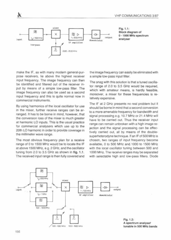
FIf.1 .1:tuock~ol'
o•1500 wtb apectrum......,..
make'" IF. as 1JL'Ith many rnociem genetaIilurpose reoeivers. ... aboY8 ee hq'IeSl recewerqlUI tr8CJJ8"CY. The lIM98 freQuency ca'l lherIbe idenbfled and lIltered out 01 the rec::ewer nput by .,.... 01 a unpe Iow-pess.... Themage freQUenCY canabo be ueed as • secondII'1)UC 1r8CJJ8"CY It'd this is qlJIte normal now inC(llTlITl8I c&al inStlVnentS,
By l/SIIlg hai••iOliiCS 0I1he IocIII 0IClIa0' tor1198
in ee mill.... Utner~ fIlI"IgeS ca'l be atrangecI. IIhas to be borne In 1TWId. however , thaithe COl'I¥elaon Iod 01.... rT'II .... is rnutfI greal...81hannonlc: LO qlUts. 1M ish usual practicetor C(llTlITl8IaaI ...,...,. 1WI'lId'I use up 10 !he20th LO harmOniC in Otdef to provide coverage In
the miIimel:er wave range ,
The most Clt\YIcluS trequency pian lor a receiverange of 0 101500 MHz 'lIWOIAd be 10ecee !he IFat above 1500 MHz... g 2 GHz, and the osciIalortuning from 2 0 10 3 5 GHz as VOwn in fi g. 1.1.The r8Oe!YecI input rllJ'l98 is then tullycovered and
the image Irequerqr C8f1easIy be *,-hIdVI'Itha 5impIe Iow-pass~Mer.
The snag WIth tns SOIubOn is thai a Iuned~.
lOr range 01 2 .0 to 3.5 GHz WOlAd be ~acI.
wtich wiltl amateur rnea"IS• • hardI'1 tNstbIe,mcw9CMll". a mixer lor .... IraQuencaM ia ,..IatrYetyexpellSlYtl .
The IF at 2 GHz preseru no real prob6am but •sroAd be borne in mIrld1h8la seooncI~to a more amenable~ torbandwlCfthandSIgI"IaIpnxessillgeg 10 .7MHzor214MHzw'"hav€ to be earned out. Thus the '8C*\Iet rnpuI,ange can remaIf'l U'tIroken WIth a hIgt1.mage reJ6diOn and the SIgliIl proces$If1Q ca'l be eeectnlely earned out . aI by mea,.. of Iha doublesuperhelerooyne IeCtnQue II an IF of 500 104Hz 15
ceoseo. two ranges 01~ frequency beaJmeavailable, 0 to 500 MHz anc11QOO 10 1500 MHzwith tile local osollalOf IuNng befweeO 500 andl000MHz. The receve ranges may be separatedwrth seectaee h'9h and Iow-pass tllters DIode
Fig. 1.2:'" ~r\,Im .nalyMl'lunab1e In sao MHz .....
~ ,' ,'oOO"H.
rr ""l'litie.c
''l 'loOO-. --"'"' ~L8J
loOO _(i(lIJ......
.,.
VHF COMMUNICATIONS 3.187
o· ?Il ~ " IF~..r~"" ;
,~- -d,"P'~Y .",.,.
~:".Y '" ~ ~ ~~ I- c- r-'" "(I.7 "~ 1 I! , "(I.""'"r.L" IrJ 8 , '- lroo'"
J ' I·U, Ii , Ii
= /: ....., I ....., ,~,
~ ~L __ _J
eoc 4 sec_' '§()()P.O -«X)IoII-'< t f n_--b 'M>l<i ....
./L ,
- fuqj'''',:y~1
/
I -~n~ % ,- -~,
to~L Odj ...l~ ...<ltl1 ~
tuned vco's are easily realized at these tre·quenoes and the translation of 500 to 10.7 MHzmay be carried out in a single step. The osadvantage 01the misSIng input sceceum rangeol500 10 1000 MHz may be overcome by employingan aOlMionallsll0covenng 1000 to 1500 MHz.This further extends the received input rangepossrblhry from 1500 to 2000 MHz The blockdiagram for this arrangement is shown in fig. 1.2.
A third possibility is represented by an IF ct t GHzbut this brings a rather more unfavourable receiverange than lhe above cases as can easily beappreciated
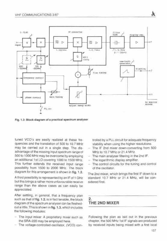
Altel selliing . in general. that a frequency plansuch as that of fig . 1.2, IS in fact tenable. the blockdiagram of the spectrum analyser can be fleshedout a lillie .This is shown in fig . 1.3. which includesthe fOllowing modules:
- The input mixer: A proprietary mille r such asthe SRA-220 may be employ9d here,
- The vcnece-cowceee-escmetor. (VCQ) con-
trolled by a Pllcircult for adequate frequencystability when uSing the higher resolutionsThe IF 2nd mixer down-converting from SOOMHz to 107 MHz or 21.4 MHz,Th6 main analyser Iillering in the 2nd IF.The logarill1mic display amplif ier.The control circuits tOI the tuning and controrof the oscillator.
The 2nd mixer. which brings the first IF down \0 astandard 10,7 MHz or 21.4 MHz, will be con.eidered first.
2.THE 2ND MIXER
Foliowing the plan as laid out in the previouschapter,the 500 MHz 1st IF signals are proclucedby received inputs being mixed with a firs! local
,"
,.,"Xl"'"Z
9O.1 MH'
VHF COMMUNICATIONS 3/87
Fig. 2.1:An IF converter withtwo conversions
- ~ 0 ~ x ~ 0, "'", 10.7 '"1, ~70 M~'
I10 lO.1 MH.
cs.. <iJd B ~
1 0 ' o;cMH,
G~
'19.3 M" ,
Fig. 2.2:An IF eeeveeter witha single conversion
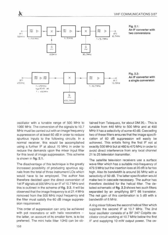
osci llator with a tunab le range of 500 MH2 to1000 MHz. The conversion of the signals to 10,7MHz must be carr ied out with an image frequencysupprssssion of at leasl 60 dB in order to reducespurious inputs to the following circu its. In anorma l receive r, this would be accomplishedusing a further IF at about 70 MHz in order toreduce the demands upon the mixer input filterfor this level of image suppression. This schemeis shown in fig : 2.1.
The disadvantage of this technique is the greaf lyincreased possib ility of produci ng spurious signals from the total of three instrument LOs whichwould have to be employed. The author hasfherefore decided upon the erect conversion at1st IF signals af500 MHz to an IF of 10.7 MHz andthis Is outlined in the scheme of f ig. 2.2. It will beobserved that the image frequency is a121.4 MHzremoved from the 500 MHz input frequency andthe filler must satisfy the 60 dB image suppression requ irement
This order of suppression can only be achievedwith pot resonators or with helix resonators the latter . on account of its sma ller form , is to bepreferred. The mini helix filter 10H3 can be ob-
' 58
tamed from Telequarz, for about OM 20,-. This istunable from 440 MHz to 500 MHz and at 450MHz it has a select ivity of some 40 dB. Cascadingtwo oteeee filters ensures that the image spec ification of 60 dB suppression wi ll easily beachieved, This entails fixing the first IF not atexactly 500 MHz but at 460 to 470 MHz in order toavoid direct interference from any local channel21 to 25 television transmitter.
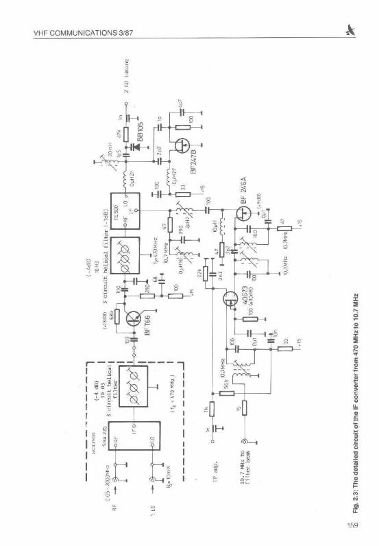
The sate llite television receivers use a surfacewave filter which has a suitable mid-frequency of479 ,5 MHz but the insertion loss at 20dB is tar reohigh. Also its bandwidth is around 35 MHz with aselect ivity of 50 dB. The latter specifi cation wou ldmake two in casc ade necessary, The author hastherefore decided lor the helical filter. The detailed schematic of fig . 2.3 shows two such filtersseparated by an ampl ifying BFT 66 transistor.The net gain of this combination is 5 dB with abandwidth of 6 MHz.
A ring mixer follows the second helical filter whichsupplies the second IF at 10.7 MHz. The 2ndlocal oscillator cons ists of a BF 247 Colpitts oscillator circu it working at 10,7 MHz below the firstIF and supplying 10 mW output power. The os-
VHF COMMU NICATIONS 3.'87
~s
"' ", ~ "g
•", w<-r N
0 " fum ,
, ",zQ,a2
sY~r ~ ", I~ ~
o~ L
L,
~:1."-,, 0 :;;'0
sI s, < "
I ~ Si l ~o '-+----1"I ' -
II
159
"Etnll-., -;1;-
e, u.-,
- Uf_~~l~
• '!IOI<
VHF COM MU NICATIONS 3187
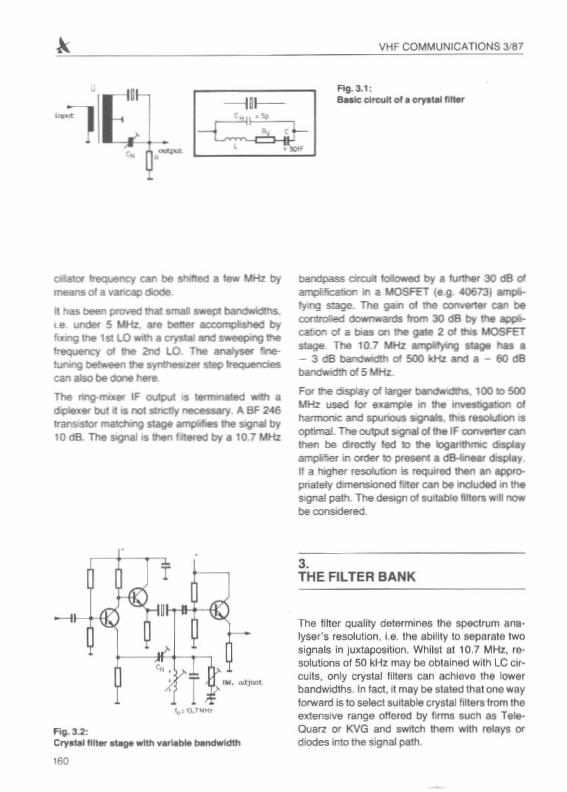
FIg.3.1 :8Nlc circuli of • Clll"'W1 n.....
aIator freQuency can be shItled a few MHz bymeans01a YCW1Ci'Ip diode.
• has been ptCI\'ed 1h8l IImlII .... bandwic:fths.I.e. undet 5 MHz. .. bener ac:c::ollwpllSheCI byfixing the 1st LO WICh a aystal and sweep; '9 the
~ 01 1ne 2nd LO , The analyser fnttuning~ ltle synu..zer~~can alSO be done here
The ring-mnrer IF output IS l8mw1ated WIth a
d.pexer but "IS no4 slndIy necessary. A BF 246tranSIstor~ stage amplifies !he SIgnal by10 dB The sigNII is then flllered by a 10.7 MHz
- u-
.... .-Ij\IIlt
1",00.·.....
Fig . 3.2:CI'\'tUIl fill.~ with ......... bwNtwIdttI
' 60
bandpass drc::uI IoIowed by a U1Fler 30 dB 01~DDn in a MOSFET (eg <1(673) ampltfyn;J stage. The gain 01 the ClCIl'7'i'8l"1er can beUll ibcAed downwards from 30 08 t:Jy the~catIOn of a bias on me gale 2 01hi MOSFETstage The 10.7 MH2 amplifying stage f\U •- J dB bandvwidlh of 500 kHz and • - 60 dBbanctwidlh of 5 MHz.
For ee cisplay of larger bandwld1hs. 100 to 500MHz used b example WI Ihe ~bOn ofharmonic and spt.Wious SIgnals,"'5 rHOlubon ISopomaI. The output SIgnal oIlhe IF ClC:lI1Wrtel" canthen be~ led Ie the lOganthmc displayamptfJef in order to present: a dB-Inear cIIsCQ'I .
If a higher resolunon is f'9QUired \hel1 an awopnately dJmensaonoo filler can be ndudecl in thes.gnaJ path. The design of surtable fillen willnowbe considered ,
3.THE FILTER BANK
The filler quality determines the spec trum ana lyser's resolution, t.e. the ability to separate twosignals in juxtaposition . Whil st 8110.7 MHz, reosolutions of 50 kHz may be obtained with l C encults, only crystal nners can ectseve the lowerbandwidths. In fact . it may be staled th at one wayforward is to select suitable crystal filters lrommeenererve ranqe o llmed by l irma such as TeleOuarz or KVG and SWItch them with relays ordiodes inlo lhe sig nal path.
VHF COMMU NICATIO NS 3/87
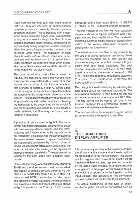
Apart lrom the tad that each liner COSIS aroundOM 150.- they are intended IOf communiCatIOnreceivers and as such are only of hmlled use tor aspectrum analyser. This is because the ir steepsided ftanll.s cause the signal-undEtr-examl'\ationto rng as II is swept through !he Mer. A moreSUitable passband is bell-shaped, possessing anellpOflefltJa lly la Ming response equally disposedabOut the centre frequency In the manner of theso-called Gaus fillers. The rea lisa tion of suchliners is real ly not so difficu lt when one is acquamted with the basic circuits of crystalliltersO lcler amateurs will recenme times when proprielry cryslal li tlers were a rarity and tillers had 10 behome-made with surplus cryst als .
The basic circuit of a quartz filler is shown infig . 3.1. The Input signal is fed in ant ipha se, froma tran sforme r to a crystal and to a presel capacitorthus forming a bridge circu it. If il is rememberedthat a crystal is basically a high Q, sertes-neeccrrcuu hav ing a para llel ho lder capacit ance thenthe function ot me bridge circuit becomes a littleclearer_The capaci tive preset arm neutralizes thestray parallel Clyslal holder capacitance leavingthe bandwidth to be deterTTllned by the ClySla l Q
and the tem llnabng resistance R. If Illis preset ISmade variable , the fiber may be tuned ova l arange Of trequenoes.
A prack:al eircuiI is shown in fig . 3.2. The trans·former has been replaced by an amplrIying stagewith two Iow-impedance outputs and the termination by an l Ccin::uit tuned lothecrystal 's nominal freqJency . This circuit has the advantage thatIhe ever-present unwanted crystal resonancesare suppressed compIeIely by this form 01t~
nallOn. An adJU$lable atlenuation , or tuning Of thetuned circuit, atlers the loading on the crystal andthereby tile cirCUit bandwidth. The output must beIoa~ by the next stage with a high er impedance.
One such filter staqe offers a select ivity of around20 dB and the refore several must be casc aded.The Sl.Jpp!y of suitable crys tals presents no problems if a quartz filter from a 50 kHz step PLl(tram an old NOBl) transceiver is taken apartand Ident ical Clystals extracted. An experimentalci rcuit WIth lourcascaded filters 01the type shownin fl g . 3.2. yielded a 1 to 20 kHz ( - 3 dB ) tunable
bandwidth and a form lactor (BW (- 3 dB)/BW(- 60 dBll of 10 - sufficienllor most purposes.
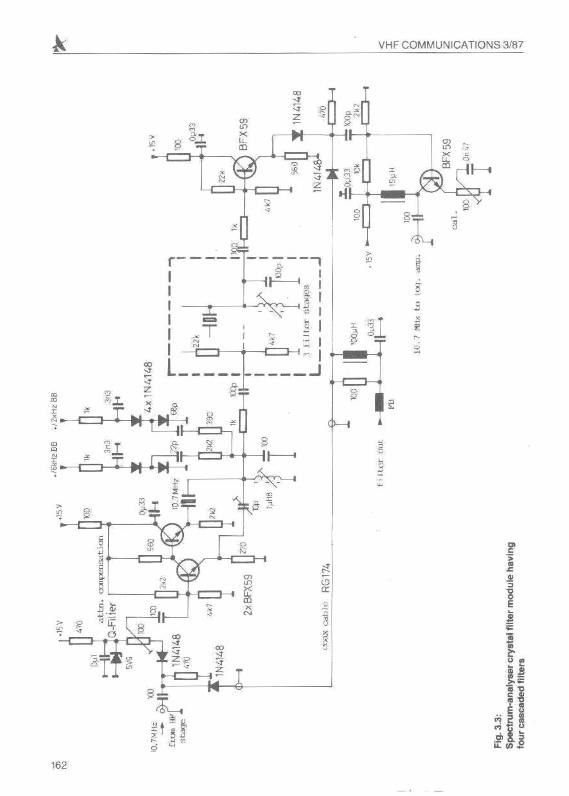
The fina l version of this filter wiII1four cascadedstages is shown in f1g .3.3. complete WIth a bypass line and fina l amplrhcaboo. The bandwidthswitching is canied out by means of 00des wtld1switch in me venous alteouabon networks inparallel with the tuned crrCUi!.
The adjustment for thiS flher is only posslble bythe use cA a sweep generator lest seI-up. Mos lcommercial sweepers are of hllle use lor thispurpose as they are no l able to SW98Pwith precision over such small oevetcos. The bestsonnon is to mak e one Irom a VCOatlO,7 MHz,tuned by a varic ap diOde ove r a range 01 ± 100kHz , The sweep frequ ency shou ld also cause theY amplif ier of an oscilloscope to traverse thetrace synchronously With n.Eac h stage is tuned indiVidually by adjusting theload tuned-eircuit lor maximum bandwidth. Thefleutralizing capacitor is lhen luned so thai theresponse curve is symmetrical about 10 .7 MHz.The fine tuning WIll be carried out tater in thefinished analyser for a symmetrical overall response and highest-possible re;ection.
The ne lrt module in the analyser·s signal path 10be considered is the Ioqanthmic amplifier .
4.THE LOGARITHMICDISPLAY AMPLIFIER
lt is nol normally consequential simply to amplifythe IF s'9nal at rrusstage and to linearty rectify itfor pres entati on to the moni tor screen. This woul dresult in signals whlcl1 l1eve at th e most a 20 dBamplitude difference being represented correctlyon the same trace Instead , an amplifier/recti fierar rangemenl is employed wh ich delivers an outpul which is proportional to the logarilhm of meinput voltage. The 8CC1Jracy of Ih is con versionprocess determ ines the leve l of me instrument.
The aelual functioning 01 this type of chainrectJfier/amplifier wiD no! be considered here as,.,
VHF COMMUNICATIONS 3/87
162
~
~
~ <~dOZ ... 13'",> 6~, s
0
~ r~<, d
" :; ;;i; "cO
~ ..n-~
I
, U,~
~ , ~
~,.
>
VHF COMMUNICATIONS 3/87
DC-output 1PI4
DC-output 2PIl
~RF-outPut
1 pt 2
pt 5 12V•
H Feedthro ugh fil terDL 8 ZX ,.tIP 0'8
NT[ l' Jl2011 k-l ( :0
f220I 100P1 L1 1S0k SOO~
lOOkRF- input ~ 3N 140 lOOp
'TPt1 40613 410k 2S~
680~y~
11e 1220 BAV18 '7
/' ~ 21k rlOOPBAV18- Gain
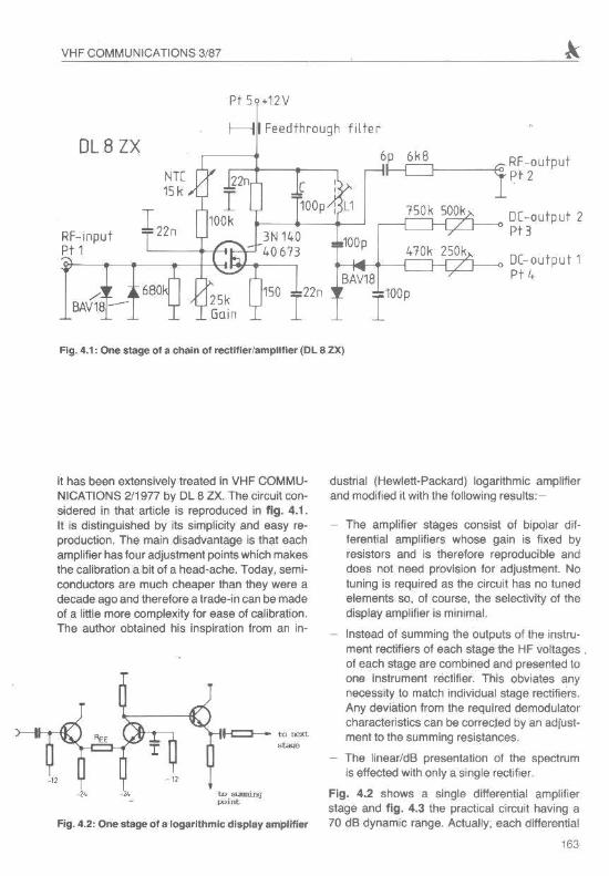
Fig. 4.1, One stage of .... ch ....ln of rectlfleriampllfler (OL 8 ZX)
Fig. 4.2, One stage of a logarithmic display amplifier
it has been extensively treated in VHF COMMUNICATIONS 211977 by DL 8 lX. The circuit considered in that article is reproduced in fig . 4.1.It is distinguished by its simplicity and easy reproduction. The main disadvantage is that eachampl ifier has four adjustment points which makesthe calibration a bit of a head-ache. Today, semiconductors are much cheaper than they were adecade ago and therefore a trade-in can be madeof a little more complexity for ease of calibration.The author obtained his inspiration from an in-
T
dustrial (Hewlett-Packard) logarithmic amplifierand modified it with the fOllowingresults:-
The amplifier stages consist of bipolar differential amplifiers whose gain is fixed byresistors and is therefore reproducible anddoes not need provision for adjustment. Notuning is required as the circuit has no tunedelements so, of course, the selectivity of thedisplay amplifier is minimal.
Instead of summing the outputs of the instrument rectifiers of each stage the HF voltages ,of each slage are combined and presented toone instrument rectifier. This obviates anynecessity to match individual stage rectifiers,Any deviation from the required demodulatorcharacteristics can be correcrec by an adjustmentto the summing resistances.
The linear/dB presentation of the spectrumis effected with only a single rectifier .
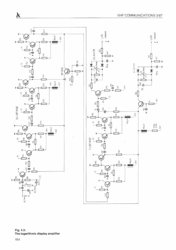
Fig. 4.2 shows a single differential amplifierstage and f ig. 4.3 the practical circuit having a70 dB dynamic range. Actually, each differential
'"
VHF COMMU NIC ATIONS 3.187
, !\ ~: •~; e
•
..- ~....:
~ :;
"•.N
\,:r~3, , ,,..,
- ,s
,s ]s I"~
l ~~ , ,•• ,· .,N
f----< .-=-0:! 1 • - - f1- t
~, , I.,
~ ;1 - J. -
,~. L<.,N _ Of ! •
,[:' , ,; r=-
~ -~ 'r, a ,,
••• ,0 '0::; - ,
; ! •--,,
'0, -.- -
e , ~,.'~_T~
~"t~ 5,~
•-.•
FIg.e.3:TheIogaftthmlc d1~r 8mpl lliel"
'64
VHF COMMUNICATIONS 3/87
..."'<>.II. 0.'
c.,
I ...1/
/ °cc
1/'" III' I
j J'
1/I
10
• 1
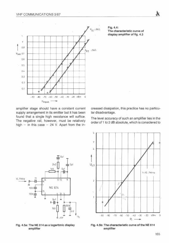
Fig. 4.4:The ch.r.cteristic curve ofdl,pllly ampuner of fig. 4.3
. ec _00 _10 _00 _50 _40 · ' 0 .aJ 08", c
ViIVJt -
amplifier stage should have a constant currentsupply arrangement in its emitter but it has beenfound that a single high resistance will suffice.The negative rail, however, must be relativelyhigh - in this case - 24 V. Apart from the in-
creased dissipation, this practice has no particular disadvantage.
The level accuracy of such an amplifier lies in theorder of 1 to 2 dB absolute, which is considered to
NE 611o
lo.~~n
oo-eeT
IIV
I/ !='Q. 1MHz
/
V1/
-90 -E\l -10 -60 -50 -1,0 -30 · 10 dam 0
~-Fig. 4.S.: The HE614 a" logarltmlc dlspllly
.mpllfterFig. 4.5b: The ch.r,cterl_1c curve of the HE614
amplifier
165
VHF COMMUN ICATIONS 3/B7
,. -- I --f-- I I I 1,
Il/" "'i '~z " ,,,
"f-,
. f--
" Vf--
" .-'-1/, •
• 1/
• I,
• I,1 I
...
1, IS"
1
I ,U,
.I.'.» .~, In ' ",;>..:; \>1
- )',. i = T"i
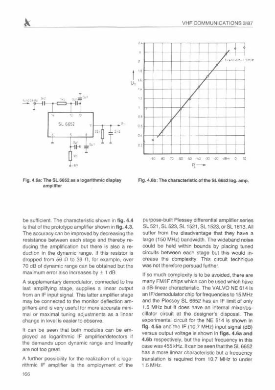
Fig. ...611:,.... Sl66s2 ee elogerlthmlCdis.pl.yemP'!ifilK
be sufllcieol. The cneractenstcshown in fig . 4.4is that 01the prototype amp lifier shown In fig. 4.3 .The accuracy can be Improlled by decreasing thereersterce between each stage and thereby reducing the amplification but there is also a reduction in the dynamic range. If this resistor isdropped from 56 n to 39 11. for example, Oller70 dB of dynam ic range can be obtained but themaximum error also increases by ± 1 dB.
A supplementary demodulator . connected to thelast ampl ifying stage. supplies a linear outpu1from an IF inpul signal. This laUer amplifier stagemay be connected to the monitol deflection amplifiers and is lIery useful for more accurate minimal or maximal tuning adjustments as a linearchange In level is easier to observe .
11 can be seen that both modules can be employed as logarithmic IF amplifier/detectors ifthe demands upon dynamic range and linearityare 1'101100 greal
A turther possibility for the realization 01 a I09anthmc IF amplifier is the employment of the
'"
purpose-built Plessey dlfferen lial ampl ilier seriesSl521.SL523.SL 1521. SL 1523.orSl 1613. AIIsutter l rom the dlsadllantage that they nave alarge (150 MHz) bandwidth. The wideband noisecould be held within bounds by placing tunedcircui ts between each stage but this would increase the complexity. This circuit techniquewas not therefore persuad further.
If so much complexity is 10 be avoided . there aremany FMl IF chips wl1ich can be used which navea dB·hnear cheractensfc. The VALVO NE 614 isan tFfdemodulator ch ip foreeccerce s10 15 MHzaru::l the Pressey SL 66 52 has an IF limit of only1.5 MHz but it does have an internal mixerfoscuero- Circuit at the designer 'S disposal. Theexperimental circuit for the NE 614 is shown infig . 4.58 and the IF (10.7 MHz) input signal (dB)versus output voaage is shown in tlga. 4.68 and".6b respecnvety. but the input frequency in thiscase was 455 kHz. It can be seen thal lhe SL 6652has a more linear characteristic but a lrequencytranslation is required from 107 MHz 10 under1.5 MHz.