Coexistence of weather radars and telecommunication systems · URSI AT-RASC, Gran Canaria, 31 May...
23
URSI AT-RASC, Gran Canaria, 31 May 2018 Coexistence of weather radars and telecommunication systems Mattia Vaccarono, V. Chandrasekar, Renzo Bechini, Roberto Cremonini 2 nd URSI Atlantic Radio Science Meeting Gran Canaria 31 May 2018
Transcript of Coexistence of weather radars and telecommunication systems · URSI AT-RASC, Gran Canaria, 31 May...

URSI AT-RASC, Gran Canaria, 31 May 2018
Coexistence of weather
radars and
telecommunication systems
Mattia Vaccarono, V. Chandrasekar, Renzo Bechini, Roberto Cremonini
2nd URSI Atlantic Radio Science Meeting
Gran Canaria 31 May 2018

URSI AT-RASC, Gran Canaria, 31 May 2018
Summary
1. Introduction
2. RFIs at C-band
1. Arpa Piemonte Bric della
Croce radar
2. RFI identification
3. Time series analysis
3. RFIs at X-band
1. Arpa Piemonte mobile radar
2. RFI identifiation
3. LTE features
4. Time series analysis
4. DFW X-band radar network
5. Conclusions
URSI AT-RASC, Gran Canaria, 31 May 2018
Introduction
RFIs at C-band RFIs at X-band
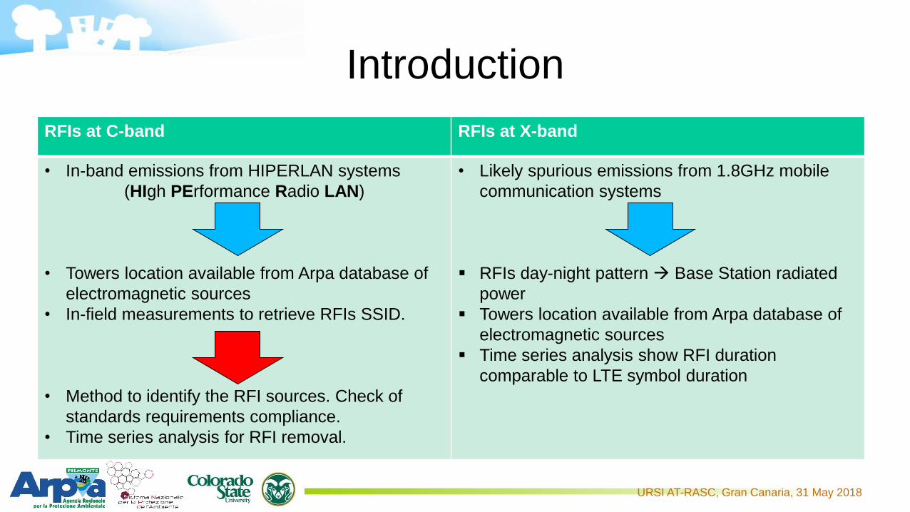
• In-band emissions from HIPERLAN systems
(HIgh PErformance Radio LAN)
• Towers location available from Arpa database of
electromagnetic sources
• In-field measurements to retrieve RFIs SSID.
• Method to identify the RFI sources. Check of
standards requirements compliance.
• Time series analysis for RFI removal.
• Likely spurious emissions from 1.8GHz mobile
communication systems
RFIs day-night pattern Base Station radiated
power
Towers location available from Arpa database of
electromagnetic sources
Time series analysis show RFI duration
comparable to LTE symbol duration

URSI AT-RASC, Gran Canaria, 31 May 2018
Introduction Frequency allocation defined in the International Telecommunication Union (ITU)
radio regulations (latest version 2016).
C-band weather radars widely used in Italy and Europe. These radars share the
frequency spectrum with RLAN and WLAN, especially HIPERLAN systems.
The 5GHz RLAN were authorized in the 5150-5350MHz and 5470-5725MHz band
after World Radiocommunication Conference 2003 (WRC-03).
Dynamic Frequency Selection (DFS) is a mandatory feature for WLAN/HIPERLAN
systems to mitigate interferences with weather radars.
No civil communication allowed in the 9300-9500MHz band.
Spurious emissions defined from standards (e.g. 3GPP – LTE, Table 9.2.1.2.1-1)
C-b
an
dX
-ba
nd
URSI AT-RASC, Gran Canaria, 31 May 2018
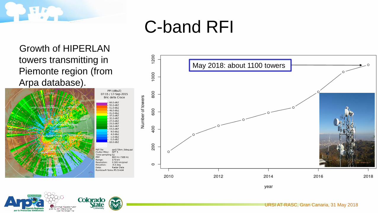
C-band RFIGrowth of HIPERLAN
towers transmitting in
Piemonte region (from
Arpa database).
May 2018: about 1100 towers

URSI AT-RASC, Gran Canaria, 31 May 2018
C-band radar -0.1° elevation
PPI acquired the 9 December 2010 at -0.1° elevation from Bric della Croce radar (TO). The same radar scan,
acquired after four year is reported in figure b. It is remarkable the interference increase.
a) b)

URSI AT-RASC, Gran Canaria, 31 May 2018
C-band radar 4.4° elevation
a) b)
PPI acquired the 9 December 2010 4.4° elevation from Bric della Croce radar (TO). The same radar scan, acquired
after four year is reported in figure b. It is remarkable the interference increase.
URSI AT-RASC, Gran Canaria, 31 May 2018
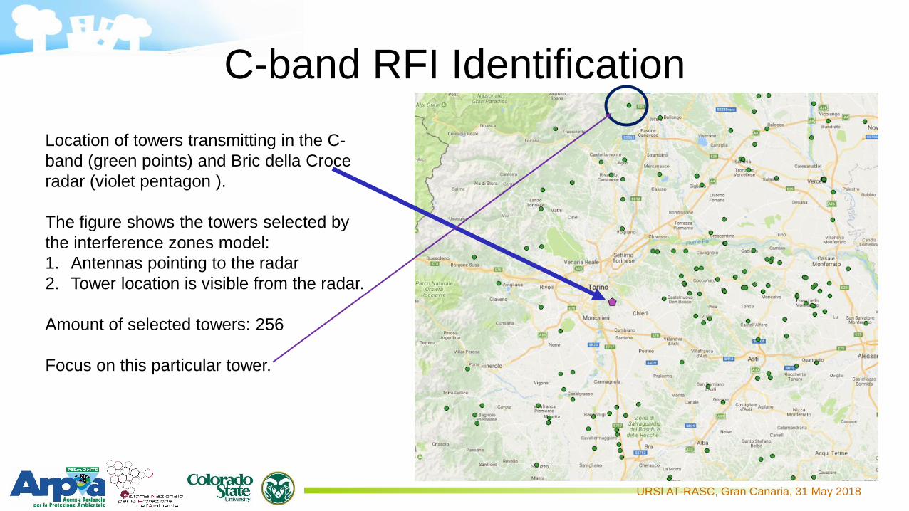
C-band RFI Identification
Location of towers transmitting in the C-
band (green points) and Bric della Croce
radar (violet pentagon ).
The figure shows the towers selected by
the interference zones model:
1. Antennas pointing to the radar
2. Tower location is visible from the radar.
Amount of selected towers: 256
Focus on this particular tower.

URSI AT-RASC, Gran Canaria, 31 May 2018
C-band RFI Identification
Bric della Croce radar
WLANExample of tower in
optical visibility with Bric
della Croce radar.
During the 2015 in-field
measurements with the
Italian Ministry of
Economic Development,
comparing the SSID
with the available
information, these
sources were found to
interfere the Bric della
Croce radar.
URSI AT-RASC, Gran Canaria, 31 May 2018
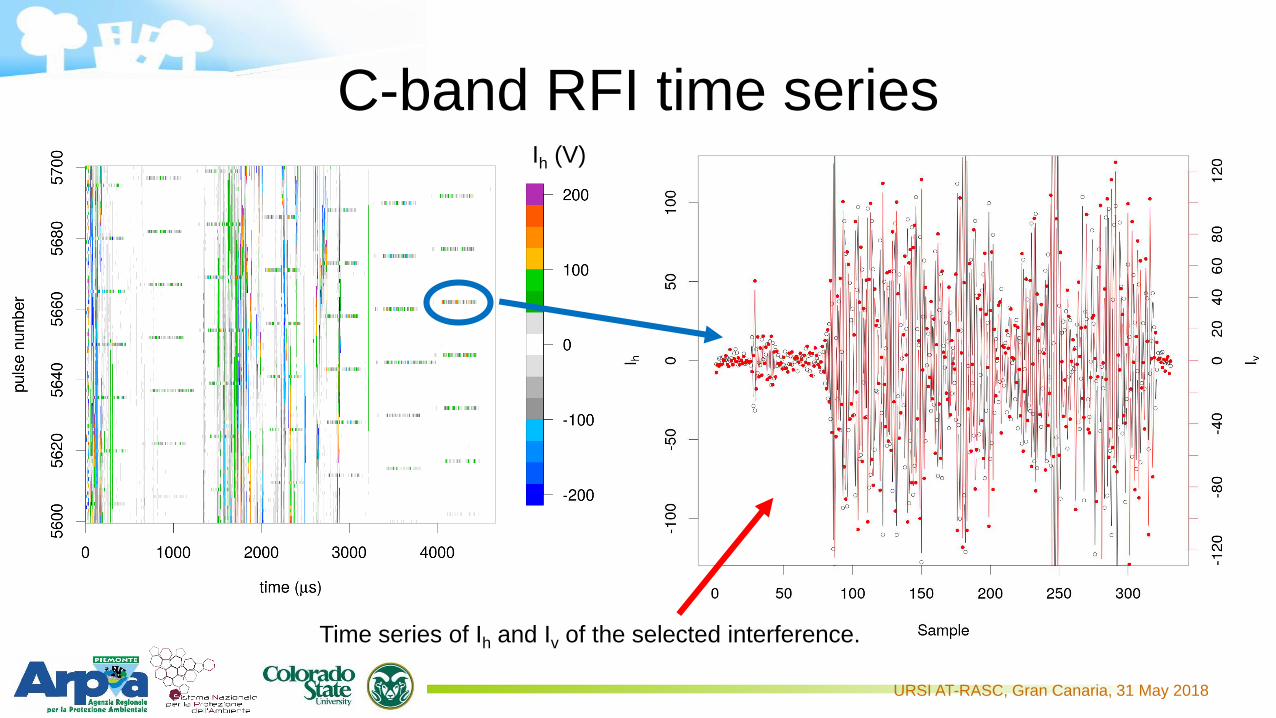
C-band RFI time series
Time series of Ih and Iv of the selected interference.
Ih (V)

URSI AT-RASC, Gran Canaria, 31 May 2018
C-band RFI time series
1st row: Iv vs Ih and Qv vs Qh plots.
Note that the data are distributed along the
-45° slope line. The RFI source is slant
polarized. Antennas slant polarization
reduces interferences and increase
performances in dense wireless
environments.
2nd row: scattergram I vs Q for h-pol and v-
pol. Unable to see any pattern.

URSI AT-RASC, Gran Canaria, 31 May 2018
X-band radar
Mobile radar used for research purposes.
Currently located near Vercelli, 60km North-East of Turin
Operational frequency: 9.366GHz
RFIs started from 2014, continuously
increasing.
Day-night pattern: RFIs received from
approximately 6 a.m. to midnight

URSI AT-RASC, Gran Canaria, 31 May 2018
X-band RFI
Maximum of echoes
received during a day (in
colors) overlapped on the
map.
The black dots represents
the Base Station of a
mobile operator
transmitting the LTE
1.8GHz.
The lines represent the ray
between the radar and the
B.S.
Note that the radar range
has been divided by 2.
Z (dBZ)

URSI AT-RASC, Gran Canaria, 31 May 2018
X-band RFI – LTE signal
OFDM based signal. Basic unit in which data are transmitted is the
LTE symbol with QAM, QPSK a CAZAC sequences as possible
modulations. Total duration of the symbol is 71.3μs and 71.9μs for
special symbols.
Down-link of the 1860-1880MHz LTE signal:
1.8732GHz x 5 = 9.366GHz which is the radar operating frequency
Maximum spurious level at X-band: -30dBm ETSI-TS 136 106 V10.0.0
This particular signal is not transmitted from midnight to 6 a.m. in
the radar area.
URSI AT-RASC, Gran Canaria, 31 May 2018
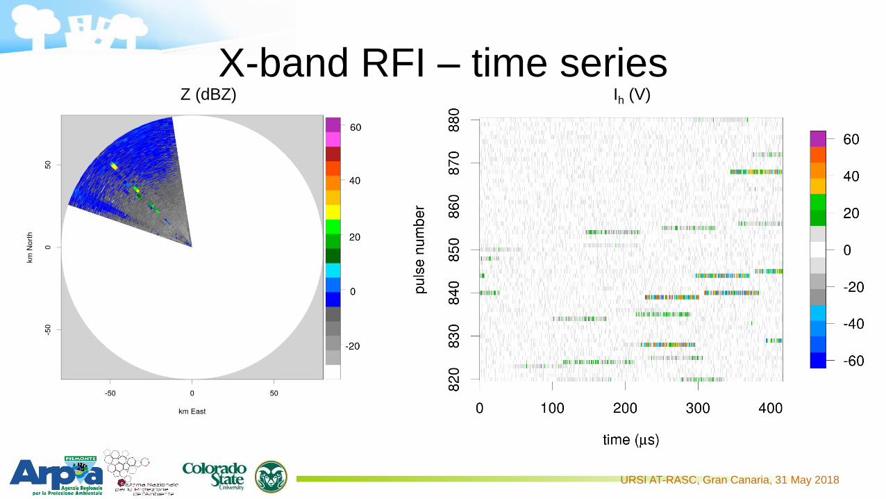
X-band RFI – time seriesZ (dBZ) Ih (V)

URSI AT-RASC, Gran Canaria, 31 May 2018
X-band RFI – time series
Scattergram I vs Q for h-pol and v-pol.
Data distributed along a circle.
Is this modulation comparable to LTE symbols?
Iv vs Ih and Qv vs Qh plots. Note that the
data are distributed elliptically along the
-45° slope line. Linearly polarized signal
reflected by the environment surfaces
during its path to the radar.
RFI duration: 71.7 μs

URSI AT-RASC, Gran Canaria, 31 May 2018
X-band RFI – time seriesReference Signals (RS) and Primary
Synchronization Signals (P-SS) may be
constructed from a Constant Amplitude Zero
AutoCorrelation sequence named Zadoff-Chu
sequence
ZC properties:
1. Constant amplitude
2. cyclic auto-correlation of each ZC
sequence results in a single impulse at
time offset zero.
1. RFI amplitude vary less than 5%;
2. RFI H-pol. autocorrelation is a single pulse at time lag zero.
URSI AT-RASC, Gran Canaria, 31 May 2018
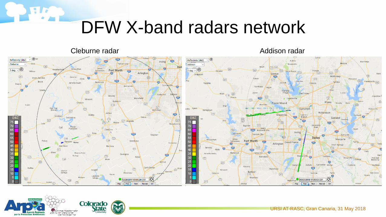
DFW X-band radars networkAddison radarCleburne radar

URSI AT-RASC, Gran Canaria, 31 May 2018
DFW X-band radars networkDFW RFIs features:
• Few interferences received per day
• High time and spatial variability
ƒ (MHz)Uplink (MHz)
(Mobile to Base)
Downlink (MHz)
(Base to Mobile)
Europe 1800 1710.2 – 1784.8 1805.2 – 1879.8
North America 1900 1850.2 – 1909.8 1930.2 – 1989.8
What is the RFI source?
No downlink communication allowed in the 1800MHz band.
Uplink of the LTE, user devices low power.
Could telecommunications affect CASA radars as Arpa X-band radar?

URSI AT-RASC, Gran Canaria, 31 May 2018
Conclusions
C-band radar:
• Broadband internet access towers cause
severe interferences
• I-Q data show high variability in the
interference duty cycle
• SSID may help to identify the interference
sources using the regional database of
electromagnetic sources
• ITU standards compliance
X-band radar:
• Day-night pattern of the received
interferences
• No in-band transmissions allowed out-of-
band or spurious emissions
• I-Q data analysis show high correlation due
to artificial source. The polarization state
(slant-pol) is widely used in mobile Base
Stations.
• Likely due to 4G mobile communications
• In-field measurement to identify which are
the interfering base stations.First step of the enhanced RFI removal tool
URSI AT-RASC, Gran Canaria, 31 May 2018

URSI AT-RASC, Gran Canaria, 31 May 2018
Bibliography
• Reed, J. H., Clegg, A. W., Padaki, A. V., Yang, T., Nealy, R., Dietrich, C., Mearns, D. M. (2016). On
the co-existence of TD-LTE and radar over 3.5 GHz band: An experimental study. IEEE
Wireless Communications Letters, 5(4), 368-371.
• Joe, P., Scott, J., Sydor, J., Brandão, A., & Yongacoglu, A. (2005, October). Radio Local Area
Network (RLAN) and C-Band Weather Radar Interference Studies. In Proc. 32nd AMS Radar
Conference on Radar Meteorology.
• Lake, J. L., Yeary, M., & Curtis, C. D. (2016, May). Effects of radio frequency interference
mitigation strategies on meteorological data. In Radar Conference (RadarConf), 2016 IEEE
(pp. 1-5). IEEE
• Horváth, Z., & Varga, D. (2009, October). Elimination of RLAN interference on weather radars
by channel allocation in 5 GHz band. In Ultra Modern Telecommunications & Workshops, 2009.
ICUMT'09. International Conference on (pp. 1-6). IEEE.
• Joseph, W., Pareit, D., Vermeeren, G., Naudts, D., Verloock, L., Martens, L., & Moerman, I. (2013).
Determination of the duty cycle of WLAN for realistic radio frequency electromagnetic field
exposure assessment. Progress in Biophysics and Molecular Biology, 111(1), 30-36.

URSI AT-RASC, Gran Canaria, 31 May 2018
Bibliography
• TRISTANT, P. (2009, September). RLAN 5 GHz interference to weather radars in Europe. In
ITU/WMO Seminar on use of radio spectrum for meteorology: Weather, Water and Climate monitoring
and prediction.
• Saltikoff, E., Cho, J. Y., Tristant, P., Huuskonen, A., Allmon, L., Cook, R.,Joe, P. (2016). The threat to
weather radars by wireless technology. Bulletin of the American Meteorological Society, 97(7), 1159-
1167.
• Keranen, R., Rojas, L., Nyberg, P. E. T. R. I. (2013). Progress in mitigation of WLAN interferences at
weather radar. In 36th Conf. on Radar Meteorology.
• LTE: Evolved Universal Terrestrial Radio Access (E-UTRA); User Equipment (UE) radio transmission and
reception ETSI TS 136 101 Technical Specification.
• LTE in a Nutshell: The Physical Layer, 2010, Telesystem Innovations Inc.
• http://webgis.arpa.piemonte.it/campi_elettromagnetici_webapp/
• https://www.ntia.doc.gov/files/ntia/publications/ntia00-40.pdf