Coexistence Concept for the Implementation of LDR/HDR WPAN ... · • Proposal of a protocol...
12
1 Introduction System scalability deals with the exploitation of the most appropriate access network/technology. The necessity for the user terminal to transmit and receive towards and from different radio access networks requires a certain level of reconfigurability of the radio interface in order to allow the exploitation of different access technologies (e.g. MC-SS, FM-UWB, etc.) and different standards (e.g. IEEE 802.11a, IEEE 802.15.3 or IEEE 802.15.4). Most of the past work on multimode terminals focused on the integration of Wireless Local Area Network (WLAN) and Cellular Wide Area Network (WAN) network terminals [1]. In addition to this kind of integration, also the different network access stan- dards defined by the IEEE 802 working groups can be integrated. IEEE 802 standards define only the physical layer (PHY) and Medium Access Control (MAC) layer of a given interface. For end-to-end services and their architectural view of the network, other core network elements have to be defined. An interesting research topic concerns the development of multimodal WPAN devices capable of exploiting simultaneously the IEEE 802.15.3-based HDR inter- face and the IEEE 802.15.4-based LDR interface [2]. This is a new concept of cooperation between access networks/technologies since there is not only a swap of access networks dictated by coverage issues or transmission rate shift, but it is envisioned a sort of cooperation aimed to enhance: QoS provisioning, power and/or bandwidth efficiency, reliability and availability. We aim to apply this concept to the multimode WPAN devices where the PHY transmis- sion bit rate of the LDR interface ranges from a few bits per second (b/s) to 100 kb/s and the transmission bit rate of the HDR interface ranging from 28.87 Mb/s to 130 Mb/s. While in such multimode terminals there exists a gap in the transmission bit rate, the features of the IEEE 802.15.3 based MAC allow to decrease the system throughput to cover this gap. The final result is the availability of an effectively integrated dual-mode WPAN device that provides a very large range of transmission bit rates seamlessly and transparently to the user. The aim of this paper is to define the guidelines for the implementation of dual mode LDR/HDR WPAN devices. The definition of guidelines encompass: • Discussion of the need to develop dual mode LDR/HDR devices by identifying several multi- mode application scenarios; • Analysis of the interference between the LDR and HDR air interfaces of reference; • Analysis of coexistence mechanisms for the mitiga- tion of the interference within a device; • Proposal of a protocol architecture which effec- tively exploits the dual mode capability of the device. In order to introduce and discuss such guidelines, we have organised the paper as follows. In Section 2 several scenarios for multimode LDR/HDR WPAN devices are proposed. Section 3 analyses the inter- ference between the two proposed AIs. In Section 4 coexistence mechanisms are discussed, while in Sec- tion 5 the protocol architecture which enables multi- mode LDR/HDR WPAN devices is proposed. Finally, conclusions are drawn in Section 6. Coexistence Concept for the Implementation of LDR/HDR WPAN Multimode Devices MAURO DE SANCTIS, JOHN GERRITS, JULIAN PÉREZ VILA Mauro De Sanctis is Assistant Professor at Department of Electronics Engineering, University of Roma “Tor Vergata”, Italy John Gerrits is with CSEM S.A. in Neuchatel, Switzerland Julián Pérez Vila is Research and Development Engineer with Telefónica I+D, Spain This paper defines the guidelines for the implementation of multimodal devices with Frequency Modulation Ultra Wide Band (FM-UWB) and Multi Carrier Spread Spectrum (MC-SS) air interfaces (AIs) for short range Low Data Rate (LDR) and High Data Rate (HDR) connections. Several novel scenarios have been proposed which require the simultaneous exploitation of LDR and HDR Wireless Personal Area Network (WPAN) connections. The possibility of performance degradation when one AI is transmitting and the other one is receiving is discussed. It has been found that MC-SS transmission can impact the FM-UWB reception. Furthermore, an overview of collaborative and non-collaborative coexistence mechanisms is provided. Finally, the architecture that allows the efficient exploitation of the two AIs in one device is proposed. 101 Telektronikk 1.2007 ISSN 0085-7130 ©Telenor ASA 2007
Transcript of Coexistence Concept for the Implementation of LDR/HDR WPAN ... · • Proposal of a protocol...
1 IntroductionSystem scalability deals with the exploitation of themost appropriate access network/technology. Thenecessity for the user terminal to transmit and receivetowards and from different radio access networksrequires a certain level of reconfigurability of theradio interface in order to allow the exploitation ofdifferent access technologies (e.g. MC-SS, FM-UWB,etc.) and different standards (e.g. IEEE 802.11a,IEEE 802.15.3 or IEEE 802.15.4).
Most of the past work on multimode terminalsfocused on the integration of Wireless Local AreaNetwork (WLAN) and Cellular Wide Area Network(WAN) network terminals [1]. In addition to this kindof integration, also the different network access stan-dards defined by the IEEE 802 working groups canbe integrated. IEEE 802 standards define only thephysical layer (PHY) and Medium Access Control(MAC) layer of a given interface. For end-to-endservices and their architectural view of the network,other core network elements have to be defined. Aninteresting research topic concerns the developmentof multimodal WPAN devices capable of exploitingsimultaneously the IEEE 802.15.3-based HDR inter-face and the IEEE 802.15.4-based LDR interface [2].This is a new concept of cooperation between accessnetworks/technologies since there is not only a swapof access networks dictated by coverage issues ortransmission rate shift, but it is envisioned a sort ofcooperation aimed to enhance: QoS provisioning,power and/or bandwidth efficiency, reliability andavailability. We aim to apply this concept to themultimode WPAN devices where the PHY transmis-sion bit rate of the LDR interface ranges from a fewbits per second (b/s) to 100 kb/s and the transmissionbit rate of the HDR interface ranging from 28.87 Mb/sto 130 Mb/s.
While in such multimode terminals there exists a gapin the transmission bit rate, the features of the IEEE802.15.3 based MAC allow to decrease the systemthroughput to cover this gap. The final result is theavailability of an effectively integrated dual-modeWPAN device that provides a very large range oftransmission bit rates seamlessly and transparentlyto the user.
The aim of this paper is to define the guidelines forthe implementation of dual mode LDR/HDR WPANdevices. The definition of guidelines encompass:
• Discussion of the need to develop dual modeLDR/HDR devices by identifying several multi-mode application scenarios;
• Analysis of the interference between the LDR andHDR air interfaces of reference;
• Analysis of coexistence mechanisms for the mitiga-tion of the interference within a device;
• Proposal of a protocol architecture which effec-tively exploits the dual mode capability of thedevice.
In order to introduce and discuss such guidelines, wehave organised the paper as follows. In Section 2several scenarios for multimode LDR/HDR WPANdevices are proposed. Section 3 analyses the inter-ference between the two proposed AIs. In Section 4coexistence mechanisms are discussed, while in Sec-tion 5 the protocol architecture which enables multi-mode LDR/HDR WPAN devices is proposed.Finally, conclusions are drawn in Section 6.
Coexistence Concept for the Implementation of LDR/HDRWPAN Multimode DevicesM A U R O D E S A N C T I S , J O H N G E R R I T S , J U L I A N P É R E Z V I L A
Mauro De
Sanctis is
Assistant
Professor at
Department of
Electronics
Engineering,
University of
Roma “Tor
Vergata”, Italy
John Gerrits is
with CSEM S.A.
in Neuchatel,
Switzerland
Julián Pérez Vila
is Research and
Development
Engineer with
Telefónica I+D,
Spain
This paper defines the guidelines for the implementation of multimodal devices with FrequencyModulation Ultra Wide Band (FM-UWB) and Multi Carrier Spread Spectrum (MC-SS) air interfaces(AIs) for short range Low Data Rate (LDR) and High Data Rate (HDR) connections. Several novelscenarios have been proposed which require the simultaneous exploitation of LDR and HDR WirelessPersonal Area Network (WPAN) connections. The possibility of performance degradation when one AIis transmitting and the other one is receiving is discussed. It has been found that MC-SS transmissioncan impact the FM-UWB reception. Furthermore, an overview of collaborative and non-collaborativecoexistence mechanisms is provided. Finally, the architecture that allows the efficient exploitation ofthe two AIs in one device is proposed.
101Telektronikk 1.2007 ISSN 0085-7130 ©Telenor ASA 2007
102 Telektronikk 1.2007
2 Multimode Application ScenariosIn this section we will define the application scenar-ios where both LDR and HDR interfaces are used.The simultaneous exploitation of the two air inter-faces within one multimode device can be dictatedby user needs, scenario requirements and/or by effi-ciency improvement. Simultaneous exploitation ofair interfaces does not mean that they simultaneouslytransmit and/or receive, but it means that both inter-faces are powered on, have established a connectionand have data to transmit or receive.
User needs can lead to multimode application scenar-ios when both LDR and HDR applications are run-ning on the same multimode device. This is the casewhere the user device is connected in LDR and HDRtransmission with several other wireless devices(mouse, headphone, printer, sensors, mobile gameplayer, file repository, etc.). In this case the data flowof one single connection is independent of each other.
On the other hand, scenario requirements can leadto the need for a multimode device (i.e. translationalbridge) capable of forwarding data received from anLDR (HDR) connection to a HDR (LDR) connection.In this case the data that flow through the HDR(LDR) connection depend on the data that flowthrough the LDR (HDR) connection.
Finally, when one of the two AIs is experiencing badtransmission conditions the user satisfaction can beenhanced by the efficient exploitation of the multi-mode capability of the devices. The mentioned badconditions can be raised by: interference with otherwireless technologies (e.g. WLAN), buffer load,remaining battery energy, coverage.
There are five different scenarios that require thesimultaneous operation of the LDR and HDR airinterfaces. In the following subsections, the fivescenarios are outlined and the main features of themultimode application scenarios are listed in Table 2.
2.1 Multimode Scenario for Multiple Traffic
– Scenario no. 1
Accounting for the application requirements in termsof minimum data rate, we can identify several cate-gories of applications for HDR and LDR AIs respec-tively. Typical applications that require LDR andHDR AIs are listed in Table 1.
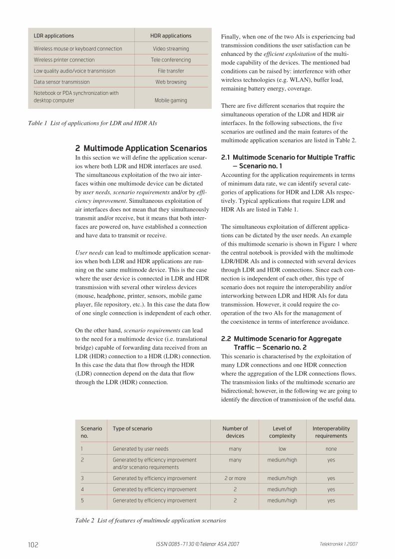
The simultaneous exploitation of different applica-tions can be dictated by the user needs. An exampleof this multimode scenario is shown in Figure 1 wherethe central notebook is provided with the multimodeLDR/HDR AIs and is connected with several devicesthrough LDR and HDR connections. Since each con-nection is independent of each other, this type ofscenario does not require the interoperability and/orinterworking between LDR and HDR AIs for datatransmission. However, it could require the co-operation of the two AIs for the management ofthe coexistence in terms of interference avoidance.
2.2 Multimode Scenario for Aggregate
Traffic – Scenario no. 2
This scenario is characterised by the exploitation ofmany LDR connections and one HDR connectionwhere the aggregation of the LDR connections flows.The transmission links of the multimode scenario arebidirectional; however, in the following we are going toidentify the direction of transmission of the useful data.
LDR applications HDR applications
Wireless mouse or keyboard connection Video streaming
Wireless printer connection Tele conferencing
Low quality audio/voice transmission File transfer
Data sensor transmission Web browsing
Notebook or PDA synchronization withdesktop computer Mobile gaming
Table 1 List of applications for LDR and HDR AIs
Scenario Type of scenario Number of Level of Interoperability
no. devices complexity requirements
1 Generated by user needs many low none
2 Generated by efficiency improvement many medium/high yesand/or scenario requirements
3 Generated by efficiency improvement 2 or more medium/high yes
4 Generated by efficiency improvement 2 medium/high yes
5 Generated by efficiency improvement 2 medium/high yes
Table 2 List of features of multimode application scenarios
ISSN 0085-7130 ©Telenor ASA 2007
103Telektronikk 1.2007
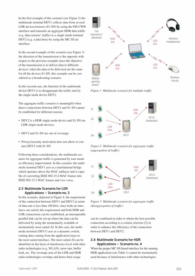
In the first example of this scenario (see Figure 2) themultimode terminal DEV1 collects data from severalLDR devices/sensors (S1-SN) by using the FM-UWBinterface and transmits an aggregate HDR data traffic(e.g. data-sensors’ traffic) to a single mode terminalDEV2 (e.g. a data base) by using the MC-SS airinterface.
In the second example of this scenario (see Figure 3)the direction of the transmission is the opposite withrespect to the previous example since the objectiveof the transmission is to deliver data to differentdevices; when the data to be delivered are the samefor all the devices S1-SN, this example can be con-sidered as a broadcasting scenario.
In this second case, the function of the multimodedevice DEV1 is to disaggregate the traffic sent bythe single mode device DEV2.
The aggregate traffic scenario is meaningful whendirect connections between DEV2 and S1-SN cannotbe established for different reasons:
• DEV2 is a HDR single mode device and S1-SN areLDR single mode devices;
• DEV2 and S1-SN are out of coverage;
• Privacy/security motivation does not allow to con-nect DEV2 with S1-SN.
Following these considerations, the multimode sce-nario for aggregate traffic is generated by user needsor efficiency improvement. In this scenario, the multi-mode terminal DEV1 acts as a translational bridgewhich operates above the MAC sublayer and is capa-ble of converting IEEE 802.15.4 MAC frames intoIEEE 802.15.3 MAC frames and vice versa.
2.3 Multimode Scenario for LDR
Applications – Scenario no. 3
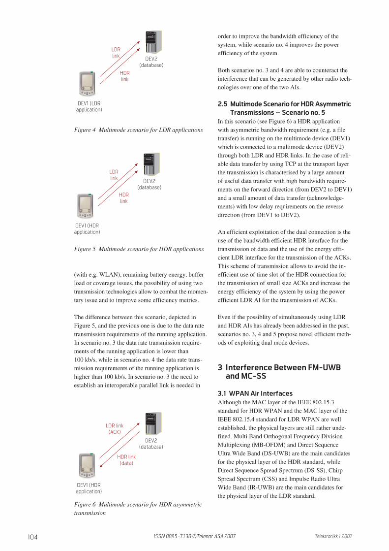
In this scenario, depicted in Figure 4, the requirementof the connection between DEV1 and DEV2 in termsof data rate is less than 100 kb/s; since both air inter-faces can satisfy this requirement and both HDR andLDR connections can be established, an interoperableparallel link can be set up where the data can bedelivered by using the momentarily available ormomentarily most suited AI. In this case, the multi-mode terminal (DEV1) acts as a dynamic switch,routing data coming from the application layer tothe most suited interface. The most suited AI can beidentified on the basis of interference level with otherradio technologies (e.g. WLAN), error rate, bufferload, etc. The coverage area of the LDR and HDRradio technologies overlaps and hence their usage
can be combined in order to obtain the best possibleconnection according to a certain criterion [3] inorder to enhance the efficiency of the connectionbetween DEV1 and DEV2.
2.4 Multimode Scenario for HDR
Applications – Scenario no. 4
When the proper MC-SS-based interface for the runningHDR application (see Table 1) cannot be momentarilyused because of interference with other technologies
HDRlink
Mobilegamingplayer
Filerepository/database Wireless
headphones
HDRlink
LDRlink
LDRlink
Wirelessmouse
S1
S2
SN
DEV2(database)
LDRlinks
HDRlink
DEV1
.
.
.
Figure 1 Multimode scenario for multiple traffic
S1
S2
SN
DEV2(database)
LDRlinks
HDRlink
DEV1
.
.
.
Figure 2 Multimode scenario for aggregate traffic(aggregation of traffic)
Figure 3 Multimode scenario for aggregate traffic(disaggregation of traffic)
ISSN 0085-7130 ©Telenor ASA 2007
104 Telektronikk 1.2007
(with e.g. WLAN), remaining battery energy, bufferload or coverage issues, the possibility of using twotransmission technologies allow to combat the momen-tary issue and to improve some efficiency metrics.
The difference between this scenario, depicted inFigure 5, and the previous one is due to the data ratetransmission requirements of the running application.In scenario no. 3 the data rate transmission require-ments of the running application is lower than100 kb/s, while in scenario no. 4 the data rate trans-mission requirements of the running application ishigher than 100 kb/s. In scenario no. 3 the need toestablish an interoperable parallel link is needed in
order to improve the bandwidth efficiency of thesystem, while scenario no. 4 improves the powerefficiency of the system.
Both scenarios no. 3 and 4 are able to counteract theinterference that can be generated by other radio tech-nologies over one of the two AIs.
2.5 Multimode Scenario for HDR Asymmetric
Transmissions – Scenario no. 5
In this scenario (see Figure 6) a HDR applicationwith asymmetric bandwidth requirement (e.g. a filetransfer) is running on the multimode device (DEV1)which is connected to a multimode device (DEV2)through both LDR and HDR links. In the case of reli-able data transfer by using TCP at the transport layerthe transmission is characterised by a large amountof useful data transfer with high bandwidth require-ments on the forward direction (from DEV2 to DEV1)and a small amount of data transfer (acknowledge-ments) with low delay requirements on the reversedirection (from DEV1 to DEV2).
An efficient exploitation of the dual connection is theuse of the bandwidth efficient HDR interface for thetransmission of data and the use of the energy effi-cient LDR interface for the transmission of the ACKs.This scheme of transmission allows to avoid the in-efficient use of time slot of the HDR connection forthe transmission of small size ACKs and increase theenergy efficiency of the system by using the powerefficient LDR AI for the transmission of ACKs.
Even if the possiblity of simultaneously using LDRand HDR AIs has already been addressed in the past,scenarios no. 3, 4 and 5 propose novel efficient meth-ods of exploiting dual mode devices.
3 Interference Between FM-UWBand MC-SS
3.1 WPAN Air Interfaces
Although the MAC layer of the IEEE 802.15.3standard for HDR WPAN and the MAC layer of theIEEE 802.15.4 standard for LDR WPAN are wellestablished, the physical layers are still rather unde-fined. Multi Band Orthogonal Frequency DivisionMultiplexing (MB-OFDM) and Direct SequenceUltra Wide Band (DS-UWB) are the main candidatesfor the physical layer of the HDR standard, whileDirect Sequence Spread Spectrum (DS-SS), ChirpSpread Spectrum (CSS) and Impulse Radio UltraWide Band (IR-UWB) are the main candidates forthe physical layer of the LDR standard.
DEV2(database)
LDRlink
HDRlink
DEV1 (LDRapplication)
DEV2(database)
LDRlink
HDRlink
DEV1 (HDRapplication)
DEV2(database)
LDR link(ACK)
HDR link(data)
DEV1 (HDRapplication)
Figure 4 Multimode scenario for LDR applications
Figure 5 Multimode scenario for HDR applications
Figure 6 Multimode scenario for HDR asymmetrictransmission
ISSN 0085-7130 ©Telenor ASA 2007
105Telektronikk 1.2007
The act of defining the two air interfaces for HDRand LDR WPAN has been fairly uncoordinated,resulting in coexistence issues of the proposed airinterfaces when operating in the same environment.
We have selected two air interfaces for LDR andHDR WPAN with the aim of minimizing systemcomplexity, energy consumption and coexistenceissues. In the following we describe the selected airinterfaces [2].
LDR Air Interface
The LDR air interface uses FM-UWB techniques and isa scalable air interface technology aimed at short-range(< 10 m) LDR (< 100 kb/s) applications, which is char-acterized by a low power consumption and ease-of-implementation on an integrated circuit [4]. FM-UWBuses double FM; a low modulation index digital Fre-quency Shift Keying (FSK) is followed by high modu-lation index analogue FM to create a constant envelopeUWB signal. The estimated power consumption is upto 3.5 mW for the transmitter and 7.5 mW for the low-complexity receiver. Though Frequency Division Mul-tiple Access (FDMA) techniques at sub-carrier levelcan be exploited to accommodate multiple users inextremely simple devices, the PHY is mainly targetedto operate with the IEEE 802.15.4 MAC, in whichTime Division Multiple Access (TDMA) is applied.
HDR Air Interface
For the HDR system, an Orthogonal Frequency Divi-sion Multiplexing (OFDM) transmission based PHYwith spreading in frequency domain is developed,which operates in the 5.2 GHz bands allocated toWireless Access Systems (WASs). The maximumdata rate without MIMO is approximately 130 Mb/sand the system bandwidth is 40 MHz; however analternative solution with 20 MHz is also specified toensure compliance with regulatory bodies. Thoughspreading in frequency domain is applied, it is notused as multiple access scheme, thus resulting in aMulti Carrier Spread Spectrum (MC-SS) transmissionscheme [5]. The chosen TDMA being compliant withthe foreseen IEEE 802.15.3 MAC scheme avoidsmultiple access interference. The objective of thefrequency domain spreading is to exploit diversityand to average out interference from other systems.Further, the number of spreading codes can be variedresulting in increased flexibility and scalability.
Interference Between LDR and HDR AIs
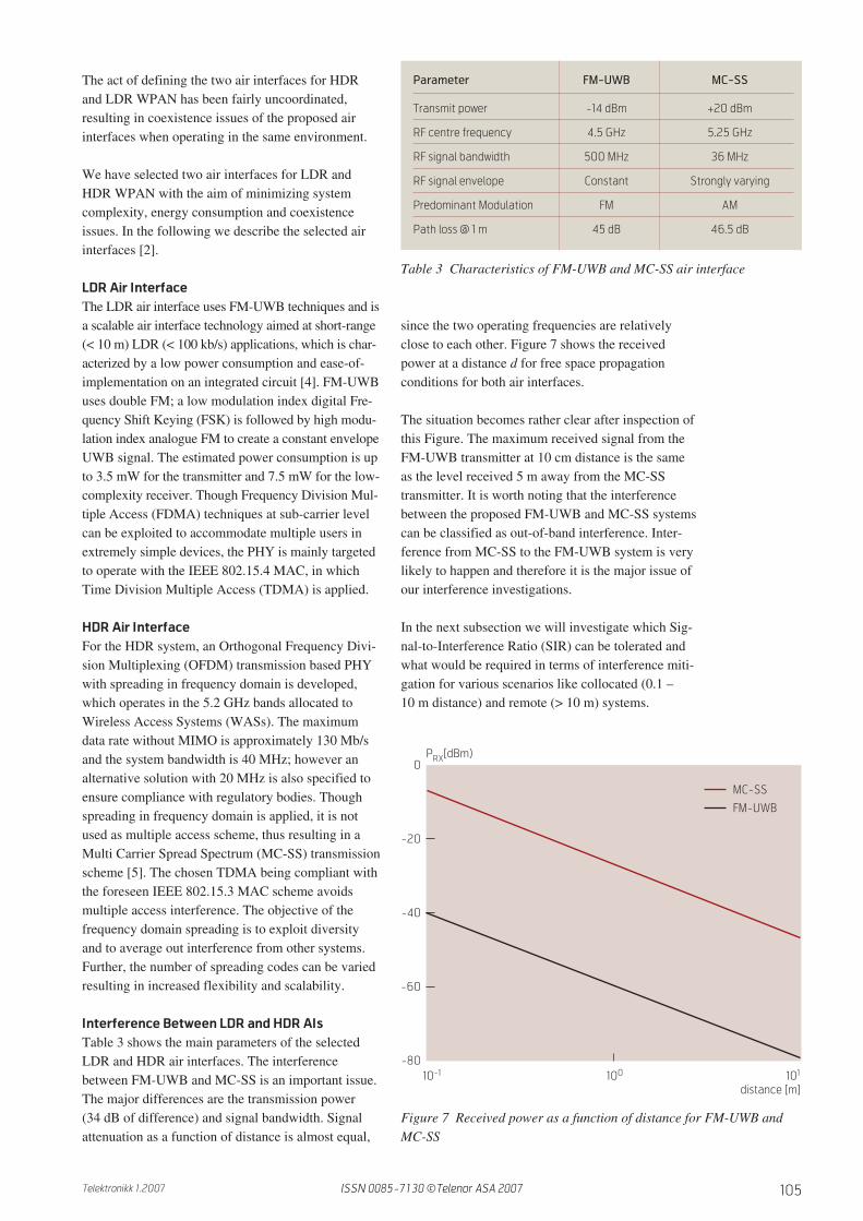
Table 3 shows the main parameters of the selectedLDR and HDR air interfaces. The interferencebetween FM-UWB and MC-SS is an important issue.The major differences are the transmission power(34 dB of difference) and signal bandwidth. Signalattenuation as a function of distance is almost equal,
since the two operating frequencies are relativelyclose to each other. Figure 7 shows the receivedpower at a distance d for free space propagationconditions for both air interfaces.
The situation becomes rather clear after inspection ofthis Figure. The maximum received signal from theFM-UWB transmitter at 10 cm distance is the sameas the level received 5 m away from the MC-SStransmitter. It is worth noting that the interferencebetween the proposed FM-UWB and MC-SS systemscan be classified as out-of-band interference. Inter-ference from MC-SS to the FM-UWB system is verylikely to happen and therefore it is the major issue ofour interference investigations.
In the next subsection we will investigate which Sig-nal-to-Interference Ratio (SIR) can be tolerated andwhat would be required in terms of interference miti-gation for various scenarios like collocated (0.1 –10 m distance) and remote (> 10 m) systems.
Parameter FM-UWB MC-SS
Transmit power -14 dBm +20 dBm
RF centre frequency 4.5 GHz 5.25 GHz
RF signal bandwidth 500 MHz 36 MHz
RF signal envelope Constant Strongly varying
Predominant Modulation FM AM
Path loss @ 1 m 45 dB 46.5 dB
Table 3 Characteristics of FM-UWB and MC-SS air interface
0
-20
-40
-60
-80100 101
distance [m]
PRX[dBm)
MC-SS
FM-UWB
10-1
Figure 7 Received power as a function of distance for FM-UWB andMC-SS
ISSN 0085-7130 ©Telenor ASA 2007
106 Telektronikk 1.2007
3.2 Influence of MC-SS on FM-UWB
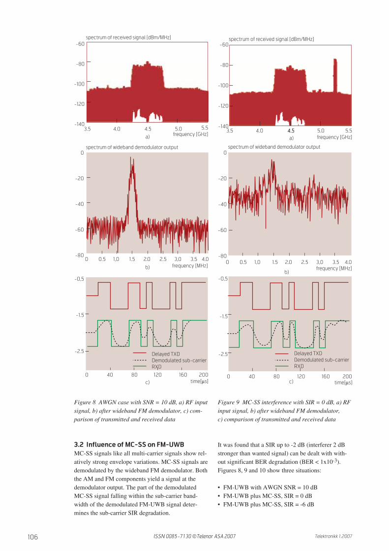
MC-SS signals like all multi-carrier signals show rel-atively strong envelope variations. MC-SS signals aredemodulated by the wideband FM demodulator. Boththe AM and FM components yield a signal at thedemodulator output. The part of the demodulatedMC-SS signal falling within the sub-carrier band-width of the demodulated FM-UWB signal deter-mines the sub-carrier SIR degradation.
It was found that a SIR up to -2 dB (interferer 2 dBstronger than wanted signal) can be dealt with with-out significant BER degradation (BER < 1x10⁻³).Figures 8, 9 and 10 show three situations:
• FM-UWB with AWGN SNR = 10 dB• FM-UWB plus MC-SS, SIR = 0 dB• FM-UWB plus MC-SS, SIR = -6 dB
b)
5.5frequency [GHz]a)
0 40 80 120 160 200
-0,5
-1.5
-2.5 Delayed TXDDemodulated sub-carrierRXD
time[µs]c)
0
-20
-40
-60
-800 0.5 1,0 1.5 2.0 2.5 3,0 3.5 4.0
-60
-80
-100
-120
-1403.5 4.0 4.5 5.0
spectrum of received signal [dBm/MHz]
frequency [MHz]
spectrum of wideband demodulator output
Figure 8 AWGN case with SNR = 10 dB, a) RF inputsignal, b) after wideband FM demodulator, c) com-parison of transmitted and received data
-60
-80
-100
-120
-140
0
-20
-40
-60
-800 0.5 1,0 1.5 2.0 2.5 3,0 3.5 4.0
0 40 80 120 160 200
-0,5
-1.5
-2.5 Delayed TXDDemodulated sub-carrierRXD
time[µs]c)
b)
3.5 4.0 4.5 5.5frequency [GHz]
spectrum of received signal [dBm/MHz]
4.5 5.0a)
frequency [MHz]
spectrum of wideband demodulator output
Figure 9 MC-SS interference with SIR = 0 dB, a) RFinput signal, b) after wideband FM demodulator, c) comparison of transmitted and received data
ISSN 0085-7130 ©Telenor ASA 2007

107Telektronikk 1.2007
For each case the following three sub-Figures areshown:
a) the spectrum of the received RF signal showing theFM-UWB signal plus interference;
b)part of the spectrum after the wideband FM demod-ulator containing the FSK sub-carrier and noise;
c) time domain view of the delayed transmitted dataTXD, the lowpass filtered FM demodulated sub-carrier signal, and its hard-limited version: thereceived data RXD.
These figures illustrate how the received data isaffected by the interference. For the sake of clarity,only a period of 200 µs (20 bits) is shown.
At SIR = 0 dB, the FM-UWB 100 kbit/s system eas-ily survives with low BER. However, the lowpassfiltered sub-carrier demodulator signal (dotted black)starts to show visible distortion.
At SIR = -6 dB (interferer 6 dB stronger than wantedsignal) the sub-carrier SNR has become too low fordemodulation.
3.2.1 Physical Layer Interference Mitigation
Techniques
The wideband FM demodulator is sensitive to bothfrequency and envelope variations of the signal [4].The red line in Figure 11 shows its transfer functionfor a delay time t equal to N = 15 times one quarterperiod of the centre frequency, i.e. 833 ps. Since thedelay line demodulator has no bandwidth limitation,MC-SS signals at 5.25 GHz will also be demodu-lated. By limiting the demodulator input signal band-width, ideally to 4.2 – 4.8 GHz, signals outside thatbandwidth will be attenuated and the interference willbe lowered. The black line in Figure 11 shows anexample of a simple bandpass filter implemented inthe LNA. The following three paragraphs addressfiltering that can be achieved inside the FM-UWB
Figure 10 MC-SS interference with SIR = -6 dB, a) RF input signal, b) after wideband FM demodula-tor, c) comparison of transmitted and received data
-60
-80
-100
-120
-140
0
-20
-40
-60
-800 0.5 1,0 1.5 2.0 2.5 3,0 3.5 4.0
spectrum of wideband demodulator output
frequency [MHz]
0 40 80 120 160 200
-0,5
-1.5
-2.5 Delayed TXDDemodulated sub-carrierRXD
time[µs]
3.5 4.0 4.5 5.5frequency [GHz]
spectrum of received signal [dBm/MHz]
5.0
c)
b)
a)
1.5
0.5
-0.5
-1.5
FM-UWB MCSS
N=15
Without BPFWith BPF Q=8
fc [GHz]4.0 4.4 4.8 5.2 5.6 6.0
Figure 11 Transfer function of the wideband FM demodulator, withand without LNA BPF
ISSN 0085-7130 ©Telenor ASA 2007
108 Telektronikk 1.2007
receiver as well as by using external filters and alsoby lowering the antenna efficiency at 5.25 GHz.
LNA Filtering
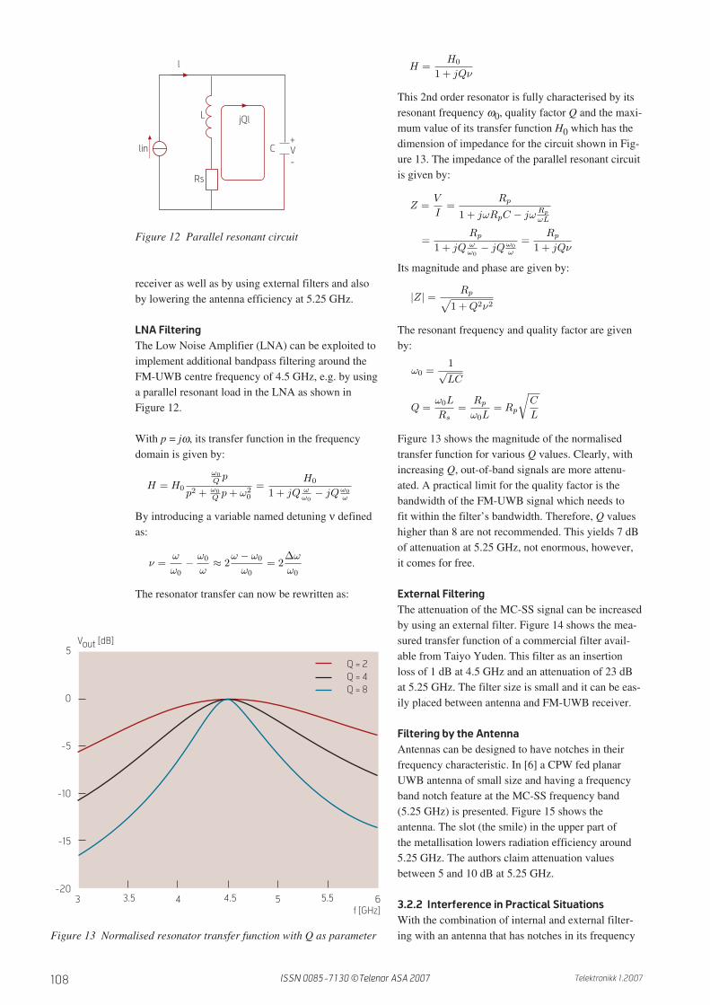
The Low Noise Amplifier (LNA) can be exploited toimplement additional bandpass filtering around theFM-UWB centre frequency of 4.5 GHz, e.g. by usinga parallel resonant load in the LNA as shown inFigure 12.
With p = jω, its transfer function in the frequencydomain is given by:
By introducing a variable named detuning ν definedas:
The resonator transfer can now be rewritten as:
This 2nd order resonator is fully characterised by itsresonant frequency ω0, quality factor Q and the maxi-mum value of its transfer function H0 which has thedimension of impedance for the circuit shown in Fig-ure 13. The impedance of the parallel resonant circuitis given by:
Its magnitude and phase are given by:
The resonant frequency and quality factor are givenby:
Figure 13 shows the magnitude of the normalisedtransfer function for various Q values. Clearly, withincreasing Q, out-of-band signals are more attenu-ated. A practical limit for the quality factor is thebandwidth of the FM-UWB signal which needs tofit within the filter’s bandwidth. Therefore, Q valueshigher than 8 are not recommended. This yields 7 dBof attenuation at 5.25 GHz, not enormous, however,it comes for free.
External Filtering
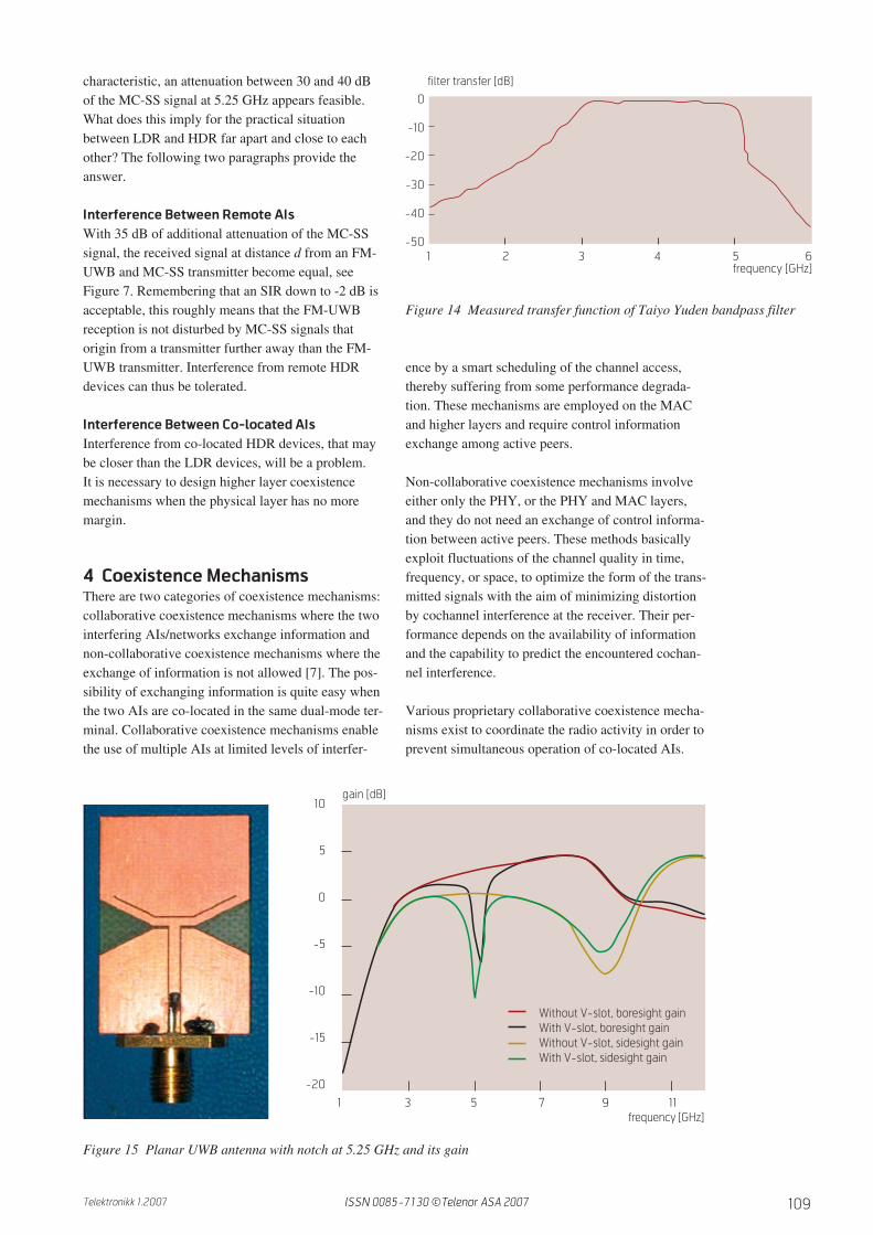
The attenuation of the MC-SS signal can be increasedby using an external filter. Figure 14 shows the mea-sured transfer function of a commercial filter avail-able from Taiyo Yuden. This filter as an insertionloss of 1 dB at 4.5 GHz and an attenuation of 23 dBat 5.25 GHz. The filter size is small and it can be eas-ily placed between antenna and FM-UWB receiver.
Filtering by the Antenna
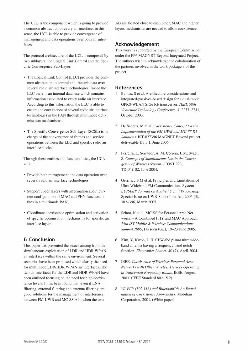
Antennas can be designed to have notches in theirfrequency characteristic. In [6] a CPW fed planarUWB antenna of small size and having a frequencyband notch feature at the MC-SS frequency band(5.25 GHz) is presented. Figure 15 shows theantenna. The slot (the smile) in the upper part ofthe metallisation lowers radiation efficiency around5.25 GHz. The authors claim attenuation valuesbetween 5 and 10 dB at 5.25 GHz.
3.2.2 Interference in Practical Situations
With the combination of internal and external filter-ing with an antenna that has notches in its frequency
H = H0
ω0
Qp
p2 +ω0
Qp + ω2
0
=H0
1 + jQ ωω0
− jQω0
ω
ν =ω
ω0
−
ω0
ω
≈ 2ω − ω0
ω0
= 2∆ω
ω0
H =H0
1 + jQν
Z =V
I=
Rp
1 + jωRpC − jωRp
ωL
=Rp
1 + jQ ω
ω0
− jQω0
ω
=Rp
1 + jQν
|Z| =Rp√
1 + Q2ν2
ω0 =1
√LC
Q =
ω0L
Rs
=
Rp
ω0L= Rp
√C
L
l
+V-
C
jQlL
Rs
lin
Figure 12 Parallel resonant circuit
f [GHz]
5
0
-5
-10
-15
-203 3.5 4 4.5 5 5.5 6
Vout [dB]
Q = 2Q = 4Q = 8
Figure 13 Normalised resonator transfer function with Q as parameter
ISSN 0085-7130 ©Telenor ASA 2007
109Telektronikk 1.2007
characteristic, an attenuation between 30 and 40 dBof the MC-SS signal at 5.25 GHz appears feasible.What does this imply for the practical situationbetween LDR and HDR far apart and close to eachother? The following two paragraphs provide theanswer.
Interference Between Remote AIs
With 35 dB of additional attenuation of the MC-SSsignal, the received signal at distance d from an FM-UWB and MC-SS transmitter become equal, seeFigure 7. Remembering that an SIR down to -2 dB isacceptable, this roughly means that the FM-UWBreception is not disturbed by MC-SS signals thatorigin from a transmitter further away than the FM-UWB transmitter. Interference from remote HDRdevices can thus be tolerated.
Interference Between Co-located AIs
Interference from co-located HDR devices, that maybe closer than the LDR devices, will be a problem.It is necessary to design higher layer coexistencemechanisms when the physical layer has no moremargin.
4 Coexistence MechanismsThere are two categories of coexistence mechanisms:collaborative coexistence mechanisms where the twointerfering AIs/networks exchange information andnon-collaborative coexistence mechanisms where theexchange of information is not allowed [7]. The pos-sibility of exchanging information is quite easy whenthe two AIs are co-located in the same dual-mode ter-minal. Collaborative coexistence mechanisms enablethe use of multiple AIs at limited levels of interfer-
ence by a smart scheduling of the channel access,thereby suffering from some performance degrada-tion. These mechanisms are employed on the MACand higher layers and require control informationexchange among active peers.
Non-collaborative coexistence mechanisms involveeither only the PHY, or the PHY and MAC layers,and they do not need an exchange of control informa-tion between active peers. These methods basicallyexploit fluctuations of the channel quality in time,frequency, or space, to optimize the form of the trans-mitted signals with the aim of minimizing distortionby cochannel interference at the receiver. Their per-formance depends on the availability of informationand the capability to predict the encountered cochan-nel interference.
Various proprietary collaborative coexistence mecha-nisms exist to coordinate the radio activity in order toprevent simultaneous operation of co-located AIs.
Figure 14 Measured transfer function of Taiyo Yuden bandpass filter
Figure 15 Planar UWB antenna with notch at 5.25 GHz and its gain
3 4 521
0
-10
-20
-30
-40
-50
frequency [GHz]6
filter transfer [dB]
10
5
0
-5
-10
-15
-20
31 5 7 9 11
Without V-slot, boresight gainWith V-slot, boresight gainWithout V-slot, sidesight gainWith V-slot, sidesight gain
frequency [GHz]
gain [dB]
ISSN 0085-7130 ©Telenor ASA 2007

110 Telektronikk 1.2007
Most of them are designed to manage the coexistenceof Bluetooth and WLAN systems [8]. The approachesvary in detail but essentially act to interleave opera-tion in order to make the operations appear simulta-neous. The techniques address the scheduling andpriority setting of the two systems, making trade-offson transmission duty cycle, idle times, and packettype (data, beacon). The packets of one system canbe sent while the other is idle and vice versa; the endeffect is to deliver reliable communication on bothsystems with a negligible loss of throughput. This is atime division approach which depends on the duplexmethod and the multiple access scheme of the two AIs.
There are three approaches that belong to the cate-gory of collaborative mechanisms:
1)Host software approaches (driver-level and dualmode switching);
2)MAC-level approaches;
3)System level approaches covering the entire wire-less sub-system.
Host Software Approaches
The host software approach is a time-divisionapproach, essentially based on the separation of theoperational periods for each AI, and it has two possi-ble implementations:
1)Dual-mode radio switching. This approach worksby completely suspending the operation of one AIwhile the other is operational. There are two meth-ods to implement it. The first method requires turn-ing off the non-operating AI without signalling toother nodes in the network. The drawback of thismethod is that it can reduce performance. The sec-
ond method acts as a signal to other network nodesthat the operation of the AI is suspended.
2)Drivel-level switching. This approach is similar tothe previous one but the functionality of control ismanaged at the driver level and it includes user-dependent switching, discriminatory switching,successful-transmission switching, statisticalswitching and time delay switching. In thisapproach, application transmit requests deliveredto the operating system, are mediated at the driverlevel, thereby avoiding simultaneous transmissionand collisions. This approach degrades the through-put because only one AI is active at a time; as aresult, systems using driver-level transmit switch-ing can suffer from dropped packets. As with dual-mode radio switching, this approach does notswitch quickly.
MAC Level Approaches
In the MAC-level switching we can apply one of thefollowing solutions: to modify either MAC layers(802.15.4-based LDR MAC and 802.15.3-basedHDR MAC) or to develop a new and self-containedmodule that communicates with both MACs.
In both cases this approach performs approximatelythe same functionality of driver level switching, butadds a predictable latency, and it would be the suit-able solution to establish high performance coexis-tence mechanism in case of real time transmissions.This technique does not suffer from transmittingsignals into incoming receptions.
Furthermore, since MAC-level switching is per-formed in the baseband, it is able to change theoperational interface at a much faster rate than hostsoftware approaches.
System Level Approaches
This approach encompass the entire wireless sub-sys-tem: for example, a driver-level switching techniquemay generate the best user experience in a low band-width synchronisation scenario, while MAC-levelswitching will manage interference much more effec-tively for real time or voice traffic, or when a user haswireless peripherals such as speakers or a keyboard.
5 Protocol ArchitectureThe protocol architecture (see Figure 16) includes theUniversal Convergence Layer (UCL) and two differ-ent radio air interface stacks, one for LDR based on aIEEE 802.15.4 medium access control layer and FM-UWB physical technology, and a second stack forHDR based on IEEE 802.15.3 medium access controllayer and MC-SS physical technology.
Logical link control
Specific convergence sub-layer
MC-SS physical
802.15.3 medium access
Universal convergence sub-layer
FM-UWB physical
802.15.4 medium access
Cross Layer Functionality
Figure 16 Protocol architecture of the multimodeterminal
ISSN 0085-7130 ©Telenor ASA 2007
111Telektronikk 1.2007
The UCL is the component which is going to providea common abstraction of every air interface; in thissense, the UCL is able to provide convergence ofmanagement and data operations over both air inter-faces.
The protocol architecture of the UCL is composed bytwo sublayers, the Logical Link Control and the Spe-cific Convergence Sub-Layer:
• The Logical Link Control (LLC) provides the com-mon abstraction to control and transmit data overseveral radio air interface technologies. Inside theLLC there is an internal database which containsinformation associated to every radio air interface.According to this information the LLC is able toensure the coexistence of several radio air interfacetechnologies in the PAN through multimode opti-misation mechanisms.
• The Specific Convergence Sub-Layer (SCSL) is incharge of the convergence of frames and serviceoperations between the LLC and specific radio airinterface stacks.
Through these entities and functionalities, the UCLwill
• Provide both management and data operation overseveral radio air interface technologies;
• Support upper layers with information about cur-rent configuration of MAC and PHY functionali-tites in a multimode PAN;
• Coordinate coexistence optimisation and activationof specific optimisation mechanisms for specific airinterface layers.
6 ConclusionThis paper has presented the issues arising from thesimultaneous exploitation of LDR and HDR WPANair interfaces within the same environment. Severalscenarios have been proposed which clarify the needfor multimode LDR/HDR WPAN air interfaces. Thetwo air interfaces for the LDR and HDR WPAN havebeen outlined focusing on the need for high coexis-tence levels. It has been found that, even if LNAfiltering, external filtering and antenna filtering aregood solutions for the management of interferencebetween FM-UWB and MC-SS AIs, when the two
AIs are located close to each other, MAC and higherlayers mechanisms are needed to allow coexistence.
AcknowledgementThis work is supported by the European Commissionunder the FP6 MAGNET Beyond Integrated Project.The authors wish to acknowledge the collaboration ofthe partners involved in the work package 3 of thisproject.
References1 Bantas, S et al. Architecture considerations and
integrated-passives-based design for a dual-modeGPRS-WLAN SiGe RF transceiver. IEEE 58thVehicular Technology Conference, 4, 2237–2241,October 2003.
2 De Sanctis, M et al. Coexistence Concept for theImplementation of the FM-UWB and MC-SS RASolutions. IST-027396 MAGNET Beyond projectdeliverable D3.3.1, June 2006.
3 Ferreira, L, Serrador, A, M. Correia, L M, Svaet,S. Concepts of Simultaneous Use in the Conver-gence of Wireless Systems. COST 273,TD(04)102, June 2004.
4 Gerrits, J F M et al. Principles and Limitations ofUltra Wideband FM Communications Systems.EURASIP Journal on Applied Signal Processing,Special Issue on UWB-State of the Art, 2005 (3),382–396, March 2005.
5 Schoo, K et al. MC-SS for Personal Area Net-works – A Combined PHY and MAC Approach.14th IST Mobile & Wireless CommunicationsSummit 2005, Dresden (GE), 19–23 June 2005.
6 Kim, Y, Kwon, D H. CPW-fed planar ultra wide-band antenna having a frequency band notchfunction. Electronics Letters, 40 (7), April 2004.
7 IEEE. Coexistence of Wireless Personal AreaNetworks with Other Wireless Devices Operatingin Unlicensed Frequency Bands. IEEE, August2003. (IEEE Standard 802.15.2)
8 Wi-Fi™ (802.11b) and Bluetooth™: An Exami-nation of Coexistence Approaches. MobilianCorporation, 2001. (White paper)
ISSN 0085-7130 ©Telenor ASA 2007

112 Telektronikk 1.2007
Mauro De Sanctis is Assistant Professor at the Department of Electronics Engineering, University of Roma
“Tor Vergata”, Italy. He received the “Laurea” degree in Telecommunications Engineering in 2002 and the
PhD degree in Telecommunications and Microelectronics Engineering in 2006 from the same university.
He was involved in the MAGNET (My personal Adaptive Global NET) European FP6 integrated project and
in the SatNEx European network of excellence; he is currently involved in the MAGNET Beyond European
FP6 integrated project as WP3/Task3 leader. In 2006 he worked as post-doctoral research fellow for the
ESA/ARIADNA extended study named “The Flower Constellation Set and its Possible Applications”. He
is/was involved in several Italian national research projects: ICONA (Integration of COmmunication and
NAvigation services) from January 2006 to December 2007, SHINES (Satellite and HAP Integrated
NEtworks and Services) from January 2003 to December 2004, CABIS (CDMA for Broadband mobile
terrestrial-satellite Integrated Systems) from January 2001 to December 2002. He was involved in the
DAVID satellite mission (DAta and Video Interactive Distribution) and is currently involved in the WAVE
satellite mission (W-band Analysis and VErification) of the ASI (Italian Space Agency). In the autumn of
2004, he joined the CTIF (Center for TeleInFrastructure), a research centre focusing on modern tele-
communcations technologies located at the University of Aalborg, Denmark. He is currently serving as
Associate Editor of the IEEEAerospace and Electronic Systems Magaqzine. His main areas of interest are:
satellite networks and constellations (in particular Flower Constellations), stratospheric platforms, resource
managment of short range wireless systems.
email: [email protected]
John F.M. Gerrits received the MScEE degree from Delft University of Technology, the Netherlands, in 1987
with final thesis on the design of integrated high-performance harmonic oscillator circuits. In 1988 he joined
the Philips T&M division in Enschede, the Netherlands, where he designed integrated oscillator and data-
acquisition systems for oscilloscope applications. In 1991 he joined CSEM in Neuchâtel, Switzerland, where
he has been involved in both system and circuit design of a single-chip low-power VHF radio receiver for
hearing aid applications and of a single-chip UHF transceiver for ISM applications. His current work involves
system and circuit design of UWB radio systems, RF and EM simulation techniques and measurement
methodology. He is currently working towards his PhD on the fundamental aspects and practical realiza-
tions of FM UWB communication systems at Delft University of Technology. He is editor and co-author of
the book Low-power design techniques and CAD tools for analog and RF integrated circuits published by
Kluwer in 2001. He is the winner of the 2006 European Conference on Wireless Technologies Prize and
holds three European and one US patent.
email: [email protected]
Julián Pérez Vila received his high engineering degree in Computer Science, Software Engineering special-
ity, from the “Universidad Pontificia de Salamanca” in Madrid, 1997-1998. Following his engineering studies
he worked as an analyst-programmer of Meta4 tools for internal systems of the company El Corte Ingles,
adapting payroll, human resource and accounting modules. In 2000 he began work in Telefonica I+D in the
“3g consultancy group”, editing and contributing several 3g reports on the demand of Telefónica Móviles,
increasing knowledge regarding multiple technologies:
• UMTS-IMS, GPRS and GSM architectures
• Ipv6, OSA and Quality of Service architectures
• Multimode terminals and data-roaming aspects
• Interoperability between Mobile Networks and Wireless LAN
• Universal user profiles, presence servers and SIP technology
After this consultancy period he contributed research and development activities related to knowledge
management and began his participation in the IST European MAGNET project, where he is coordinating
the research and development contributions to the areas of context management in personal networks
and multimode radio air interface technologies.
email: [email protected]
ISSN 0085-7130 ©Telenor ASA 2007