CodeWarrior Development Studio for StarCore …Section number Title Page 5.2.2.7.2 CodeWarrior TAP -...
361
CodeWarrior Development Studio for StarCore 3900FP DSP Architectures Targeting Manual Document Number: CWSCDBGUG Rev. 10.9.0, 11/2015
Transcript of CodeWarrior Development Studio for StarCore …Section number Title Page 5.2.2.7.2 CodeWarrior TAP -...

CodeWarrior Development Studio forStarCore 3900FP DSP Architectures
Targeting Manual
Document Number: CWSCDBGUGRev. 10.9.0, 11/2015

CodeWarrior Development Studio for StarCore 3900FP DSP Architectures Targeting Manual, Rev. 10.9.0,11/2015
2 Freescale Semiconductor, Inc.

Contents
Section number Title Page
Chapter 1Introduction
1.1 Release notes...................................................................................................................................................................17
1.2 Contents of this manual.................................................................................................................................................. 17
1.3 Accompanying documentation....................................................................................................................................... 18
1.4 CodeWarrior Development Studio tools.........................................................................................................................19
1.4.1 Eclipse IDE........................................................................................................................................................ 19
1.4.2 C Compiler.........................................................................................................................................................20
1.4.3 Assembler...........................................................................................................................................................20
1.4.4 Linker................................................................................................................................................................. 21
1.4.5 Debugger............................................................................................................................................................21
1.4.6 CodeWarrior Profiling and Analysis tools.........................................................................................................21
1.5 CodeWarrior IDE............................................................................................................................................................22
1.5.1 Project files........................................................................................................................................................ 23
1.5.2 Code editing....................................................................................................................................................... 23
1.5.3 Compiling...........................................................................................................................................................24
1.5.4 Linking............................................................................................................................................................... 24
1.5.5 Debugging..........................................................................................................................................................24
Chapter 2Working with Projects
2.1 CodeWarrior Bareboard Project Wizard.........................................................................................................................27
2.1.1 Create a CodeWarrior Bareboard Project Page..................................................................................................28
2.1.2 Processor Page................................................................................................................................................... 29
2.1.3 Debug Target Settings Page...............................................................................................................................30
2.1.4 Build Settings Page............................................................................................................................................ 32
2.1.5 SmartDSP OS Page............................................................................................................................................34
2.2 Creating projects............................................................................................................................................................. 35
2.2.1 Creating CodeWarrior Bareboard Project..........................................................................................................35
CodeWarrior Development Studio for StarCore 3900FP DSP Architectures Targeting Manual, Rev. 10.9.0,11/2015
Freescale Semiconductor, Inc. 3

Section number Title Page
2.3 Importing Projects...........................................................................................................................................................38
2.3.1 Importing SmartDSP OS Project....................................................................................................................... 38
2.4 Building projects.............................................................................................................................................................43
2.4.1 Manual-Build mode........................................................................................................................................... 43
2.4.2 Auto-Build mode................................................................................................................................................45
2.5 Deleting Projects.............................................................................................................................................................46
Chapter 3Build Properties
3.1 Changing Build Properties..............................................................................................................................................47
3.2 Restoring Build Properties..............................................................................................................................................48
3.3 Build Properties for StarCore..........................................................................................................................................48
3.3.1 StarCore Environment........................................................................................................................................50
3.3.2 StarCore 3900 Disassembler..............................................................................................................................52
3.3.2.1 Disassembler Settings........................................................................................................................ 53
3.3.3 StarCore 3900 C/C++ Linker Application ........................................................................................................ 55
3.3.3.1 Linker Settings................................................................................................................................... 56
3.3.3.2 C/C++ Options .................................................................................................................................. 57
3.3.3.3 Libraries............................................................................................................................................. 58
3.3.4 StarCore 3900 C/C++ Compiler ....................................................................................................................... 60
3.3.4.1 C/C++ Language................................................................................................................................ 61
3.3.4.2 Control............................................................................................................................................... 63
3.3.4.3 Hardware Configuration.................................................................................................................... 64
3.3.4.4 Output Listing.................................................................................................................................... 65
3.3.4.5 Warnings............................................................................................................................................ 67
3.3.4.5.1 Compiler Front End Messages........................................................................................68
3.3.4.5.2 Assembler....................................................................................................................... 71
3.3.4.5.3 Linker..............................................................................................................................72
3.3.4.6 Include Search Paths.......................................................................................................................... 73
3.3.4.7 Macros................................................................................................................................................75
CodeWarrior Development Studio for StarCore 3900FP DSP Architectures Targeting Manual, Rev. 10.9.0,11/2015
4 Freescale Semiconductor, Inc.

Section number Title Page
3.3.4.8 Processor............................................................................................................................................ 77
3.3.4.9 Optimization.......................................................................................................................................78
3.3.4.10 Configuration Files............................................................................................................................ 81
3.3.4.11 Additional Arguments........................................................................................................................82
3.3.5 StarCore 3900 Assembler ................................................................................................................................. 83
3.3.5.1 Code and Language Options.............................................................................................................. 84
3.3.5.2 Include Search Paths.......................................................................................................................... 88
3.3.5.3 Preprocessor....................................................................................................................................... 90
3.3.5.4 Listing File......................................................................................................................................... 92
3.3.5.5 Listing Contents................................................................................................................................. 94
3.3.5.6 Listing Format....................................................................................................................................96
3.3.5.7 Additional Arguments........................................................................................................................98
3.3.6 StarCore 3900 Preprocessor...............................................................................................................................99
3.3.6.1 Preprocessor Settings......................................................................................................................... 100
Chapter 4Debug Configurations
4.1 Using Debug Configurations Dialog Box.......................................................................................................................103
4.1.1 Main................................................................................................................................................................... 104
4.1.1.1 Debug Session Type ..........................................................................................................................105
4.1.1.1.1 Attach .............................................................................................................................107
4.1.1.1.2 Connect .......................................................................................................................... 108
4.1.1.1.3 Download .......................................................................................................................108
4.1.1.1.4 Custom ........................................................................................................................... 109
4.1.1.2 C/C++ application.............................................................................................................................. 109
4.1.1.3 Build (if required) before launching ................................................................................................. 110
4.1.1.4 Target settings.................................................................................................................................... 111
4.1.2 Arguments..........................................................................................................................................................111
4.1.3 Debugger............................................................................................................................................................112
4.1.3.1 Debug................................................................................................................................................. 114
CodeWarrior Development Studio for StarCore 3900FP DSP Architectures Targeting Manual, Rev. 10.9.0,11/2015
Freescale Semiconductor, Inc. 5
Section number Title Page
4.1.3.2 Download........................................................................................................................................... 115
4.1.3.3 Other Executables.............................................................................................................................. 117
4.1.3.4 Symbolics...........................................................................................................................................118
4.1.3.5 OS Awareness.................................................................................................................................... 120
4.1.4 Source.................................................................................................................................................................121
4.1.5 Environment.......................................................................................................................................................123
4.1.6 Common.............................................................................................................................................................124
4.1.7 Trace and Profile................................................................................................................................................125
4.2 Customizing Debug Configurations............................................................................................................................... 129
4.3 Reverting Debug Configuration Settings........................................................................................................................131
Chapter 5Working with Debugger
5.1 Debugging a CodeWarrior project..................................................................................................................................133
5.1.1 Debugging Project Using Simulator.................................................................................................................. 134
5.1.2 Debugging Project using Target Hardware........................................................................................................137
5.2 Configuring Connections................................................................................................................................................140
5.2.1 CodeWarrior Connection Server........................................................................................................................141
5.2.1.1 Running CCS..................................................................................................................................... 142
5.2.1.2 Displaying CCS Console................................................................................................................... 142
5.2.1.3 Configuring CCS................................................................................................................................143
5.2.2 Connection types................................................................................................................................................144
5.2.2.1 CCSSIM2 ISS.................................................................................................................................... 144
5.2.2.2 CCSSIM2 PACC................................................................................................................................146
5.2.2.3 Ethernet TAP......................................................................................................................................147
5.2.2.4 Gigabit TAP + Trace..........................................................................................................................149
5.2.2.5 Gigabit TAP....................................................................................................................................... 151
5.2.2.6 USB TAP........................................................................................................................................... 153
5.2.2.7 CodeWarrior TAP.............................................................................................................................. 154
5.2.2.7.1 CodeWarrior TAP - JTAG Connection through USB.................................................... 156
CodeWarrior Development Studio for StarCore 3900FP DSP Architectures Targeting Manual, Rev. 10.9.0,11/2015
6 Freescale Semiconductor, Inc.

Section number Title Page
5.2.2.7.2 CodeWarrior TAP - JTAG Connection through Ethernet.............................................. 157
5.3 Editing remote system configuration..............................................................................................................................158
5.3.1 Initialization tab................................................................................................................................................. 159
5.3.2 Memory tab........................................................................................................................................................ 160
5.3.3 I/O Model Tab....................................................................................................................................................161
5.3.4 Advanced tab......................................................................................................................................................162
5.4 Working with Breakpoints..............................................................................................................................................162
5.4.1 Setting Breakpoints............................................................................................................................................ 163
5.4.2 Setting Hardware Breakpoints........................................................................................................................... 165
5.4.2.1 Using IDE to Set Hardware Breakpoints........................................................................................... 166
5.4.2.2 Using Debugger Shell to Set Hardware Breakpoints.........................................................................166
5.4.3 Removing Breakpoints.......................................................................................................................................167
5.4.3.1 Remove Breakpoints using Marker Bar.............................................................................................167
5.4.3.2 Remove Breakpoints using Breakpoints View.................................................................................. 167
5.4.4 Removing Hardware Breakpoints......................................................................................................................168
5.4.4.1 Remove Hardware Breakpoints using the IDE.................................................................................. 168
5.4.4.2 Remove Hardware Breakpoints using Debugger Shell......................................................................169
5.5 Working with Watchpoints.............................................................................................................................................169
5.5.1 Setting Watchpoints........................................................................................................................................... 170
5.5.2 Removing Watchpoints......................................................................................................................................172
5.6 Working with Registers.................................................................................................................................................. 172
5.6.1 Viewing Register Details................................................................................................................................... 174
5.6.1.1 Bit Fields............................................................................................................................................ 175
5.6.1.2 Changing Bit Fields........................................................................................................................... 176
5.6.1.3 Actions............................................................................................................................................... 177
5.6.1.4 Description......................................................................................................................................... 178
5.6.2 Registers View Context Menu........................................................................................................................... 178
5.6.3 Working with Register Groups.......................................................................................................................... 179
5.6.3.1 Adding a Register Group................................................................................................................... 180
CodeWarrior Development Studio for StarCore 3900FP DSP Architectures Targeting Manual, Rev. 10.9.0,11/2015
Freescale Semiconductor, Inc. 7
Section number Title Page
5.6.3.2 Editing a Register Group....................................................................................................................181
5.6.3.3 Removing a Register Group...............................................................................................................181
5.7 Viewing memory............................................................................................................................................................ 182
5.7.1 Adding Memory Monitor...................................................................................................................................182
5.7.2 Adding Memory Rendering............................................................................................................................... 185
5.7.3 Removing Memory Rendering...........................................................................................................................186
5.7.4 Resetting to Base Address..................................................................................................................................186
5.7.5 Go to Address.....................................................................................................................................................187
5.8 Viewing Cache................................................................................................................................................................187
5.8.1 Cache View........................................................................................................................................................ 188
5.8.2 Cache View Toolbar Menu................................................................................................................................ 190
5.9 Changing Program Counter Value..................................................................................................................................191
5.10 Hard resetting..................................................................................................................................................................192
5.11 Per Core Reset ................................................................................................................................................................192
5.12 Setting Stack Depth.........................................................................................................................................................193
5.13 Import a CodeWarrior Executable file Wizard...............................................................................................................194
5.13.1 Import a CodeWarrior Executable file Page...................................................................................................... 195
5.13.2 Import C/C++/Assembler Executable Files Page.............................................................................................. 196
5.13.3 Processor Page................................................................................................................................................... 197
5.13.4 Debug Target Settings Page...............................................................................................................................197
5.14 Debugging Externally Built Executable Files.................................................................................................................199
5.14.1 Import an Executable File.................................................................................................................................. 199
5.14.2 Edit the Launch Configuration...........................................................................................................................201
5.14.3 Specify the Source Lookup Path........................................................................................................................201
5.14.3.1 Automatic Path Mapping................................................................................................................... 202
5.14.3.2 Manual Path Mapping .......................................................................................................................204
5.14.4 Debug Executable File....................................................................................................................................... 209
CodeWarrior Development Studio for StarCore 3900FP DSP Architectures Targeting Manual, Rev. 10.9.0,11/2015
8 Freescale Semiconductor, Inc.

Section number Title Page
Chapter 6Target Initialization File
Chapter 7Memory Configuration File
Chapter 8CodeWarrior Command-Line Debugging
8.1 Working with Debugger Shell ....................................................................................................................................... 215
8.2 Tcl Support......................................................................................................................................................................218
8.2.1 Resolution of Conflicting Command Names..................................................................................................... 218
8.2.2 Execution of Script Files....................................................................................................................................218
8.2.3 Tcl Startup Script............................................................................................................................................... 219
8.3 Command-Line Debugging Tasks ................................................................................................................................. 220
8.4 Debugger Shell Command List ......................................................................................................................................220
8.4.1 about ..................................................................................................................................................................221
8.4.2 alias.................................................................................................................................................................... 222
8.4.3 bp........................................................................................................................................................................222
8.4.4 cd .......................................................................................................................................................................223
8.4.5 change ............................................................................................................................................................... 224
8.4.6 cls ...................................................................................................................................................................... 226
8.4.7 config................................................................................................................................................................. 226
8.4.8 copy ...................................................................................................................................................................228
8.4.9 debug .................................................................................................................................................................229
8.4.10 dir ...................................................................................................................................................................... 229
8.4.11 disassemble ....................................................................................................................................................... 230
8.4.12 display ............................................................................................................................................................... 231
8.4.13 evaluate.............................................................................................................................................................. 233
8.4.14 finish...................................................................................................................................................................234
8.4.15 fl::blankcheck.....................................................................................................................................................234
8.4.16 fl::checksum....................................................................................................................................................... 234
8.4.17 fl::device.............................................................................................................................................................235
CodeWarrior Development Studio for StarCore 3900FP DSP Architectures Targeting Manual, Rev. 10.9.0,11/2015
Freescale Semiconductor, Inc. 9

Section number Title Page
8.4.18 fl::diagnose.........................................................................................................................................................235
8.4.19 fl::disconnect......................................................................................................................................................235
8.4.20 fl::dump..............................................................................................................................................................235
8.4.21 fl::erase...............................................................................................................................................................236
8.4.22 fl::image............................................................................................................................................................. 236
8.4.23 fl::protect............................................................................................................................................................236
8.4.24 fl::secure.............................................................................................................................................................237
8.4.25 fl::target..............................................................................................................................................................237
8.4.26 fl::verify............................................................................................................................................................. 237
8.4.27 fl::write...............................................................................................................................................................238
8.4.28 funcs................................................................................................................................................................... 238
8.4.29 getIDEpref..........................................................................................................................................................238
8.4.30 getpid..................................................................................................................................................................239
8.4.31 go........................................................................................................................................................................239
8.4.32 help.....................................................................................................................................................................240
8.4.33 history.................................................................................................................................................................240
8.4.34 jtagclock............................................................................................................................................................. 241
8.4.35 kill...................................................................................................................................................................... 241
8.4.36 launch................................................................................................................................................................. 242
8.4.37 loadsym.............................................................................................................................................................. 242
8.4.38 log.......................................................................................................................................................................242
8.4.39 mc::config.......................................................................................................................................................... 243
8.4.40 mc::go.................................................................................................................................................................243
8.4.41 mc::group........................................................................................................................................................... 244
8.4.42 mc::kill............................................................................................................................................................... 244
8.4.43 mc::reset ............................................................................................................................................................ 244
8.4.44 mc::restart ..........................................................................................................................................................244
8.4.45 mc::stop..............................................................................................................................................................245
8.4.46 mc::type..............................................................................................................................................................245
CodeWarrior Development Studio for StarCore 3900FP DSP Architectures Targeting Manual, Rev. 10.9.0,11/2015
10 Freescale Semiconductor, Inc.
Section number Title Page
8.4.47 mem....................................................................................................................................................................245
8.4.48 next.....................................................................................................................................................................247
8.4.49 nexti....................................................................................................................................................................248
8.4.50 oneframe.............................................................................................................................................................248
8.4.51 protocol.............................................................................................................................................................. 248
8.4.52 pwd.....................................................................................................................................................................248
8.4.53 quitIDE...............................................................................................................................................................249
8.4.54 radix................................................................................................................................................................... 249
8.4.55 redirect............................................................................................................................................................... 250
8.4.56 refresh.................................................................................................................................................................250
8.4.57 reg.......................................................................................................................................................................250
8.4.58 reset.................................................................................................................................................................... 250
8.4.59 restart..................................................................................................................................................................251
8.4.60 restore.................................................................................................................................................................251
8.4.61 run...................................................................................................................................................................... 251
8.4.62 save.....................................................................................................................................................................251
8.4.63 sc::setMaxAccessLength....................................................................................................................................252
8.4.64 sc::setReset.........................................................................................................................................................253
8.4.65 sc::getPhysicalAddress.......................................................................................................................................253
8.4.66 setpc................................................................................................................................................................... 253
8.4.67 setpicloadaddr.................................................................................................................................................... 253
8.4.68 stack................................................................................................................................................................... 254
8.4.69 status...................................................................................................................................................................254
8.4.70 step..................................................................................................................................................................... 254
8.4.71 stepi.................................................................................................................................................................... 255
8.4.72 stop..................................................................................................................................................................... 255
8.4.73 switchtarget........................................................................................................................................................ 256
8.4.74 system.................................................................................................................................................................256
8.4.75 var.......................................................................................................................................................................257
CodeWarrior Development Studio for StarCore 3900FP DSP Architectures Targeting Manual, Rev. 10.9.0,11/2015
Freescale Semiconductor, Inc. 11

Section number Title Page
8.4.76 wait.....................................................................................................................................................................258
8.4.77 watchpoint..........................................................................................................................................................259
Chapter 9Multi-Core Debugging
9.1 Creating a JTAG Initialization File.................................................................................................................................261
9.2 Debugging Multi-Core Projects......................................................................................................................................262
9.2.1 Setting Launch Configurations.......................................................................................................................... 263
9.2.2 Debugging Multiple Cores.................................................................................................................................268
9.3 Multi-Core Debugging Commands.................................................................................................................................272
9.3.1 Multi-Core Commands in CodeWarrior IDE.....................................................................................................272
9.3.2 Multi-Core Commands in Debugger Shell........................................................................................................ 274
Chapter 10Working with Hardware Tools
10.1 Flash programmer........................................................................................................................................................... 277
10.1.1 Create a flash programmer target task............................................................................................................... 278
10.1.2 Configure flash programmer target task............................................................................................................ 280
10.1.2.1 Add flash device.................................................................................................................................280
10.1.2.2 Specify target RAM settings.............................................................................................................. 281
10.1.2.3 Add flash programmer actions...........................................................................................................281
10.1.2.3.1 Erase/Blank check actions.............................................................................................. 282
10.1.2.3.2 Program/Verify actions...................................................................................................283
10.1.2.3.3 Checksum actions........................................................................................................... 284
10.1.2.3.4 Diagnostics actions......................................................................................................... 285
10.1.2.3.5 Dump Flash actions........................................................................................................ 286
10.1.2.3.6 Protect/Unprotect actions................................................................................................286
10.1.2.3.7 Duplicate action.............................................................................................................. 287
10.1.2.3.8 Remove action................................................................................................................ 287
10.1.3 Execute flash programmer target task................................................................................................................287
CodeWarrior Development Studio for StarCore 3900FP DSP Architectures Targeting Manual, Rev. 10.9.0,11/2015
12 Freescale Semiconductor, Inc.

Section number Title Page
10.1.4 Flash Programmer Use Case.............................................................................................................................. 289
10.1.4.1 Using Flash Programmer to Write uboot Image to Target.................................................................289
10.2 Flash File to Target......................................................................................................................................................... 291
10.2.1 Erasing flash device........................................................................................................................................... 292
10.2.2 Programming a file.............................................................................................................................................293
10.3 Hardware diagnostics......................................................................................................................................................294
10.3.1 Creating hardware diagnostics task....................................................................................................................294
10.3.2 Working with Hardware Diagnostic Action editor............................................................................................ 295
10.3.2.1 Action Type........................................................................................................................................296
10.3.2.2 Memory Access..................................................................................................................................297
10.3.2.3 Loop Speed........................................................................................................................................ 297
10.3.2.4 Memory Tests.................................................................................................................................... 298
10.3.2.4.1 Walking Ones..................................................................................................................299
10.3.2.4.2 Address........................................................................................................................... 300
10.3.2.4.3 Bus noise.........................................................................................................................300
10.3.2.4.4 Address lines...................................................................................................................300
10.3.2.4.5 Data lines........................................................................................................................ 301
10.3.3 Memory test use cases........................................................................................................................................302
10.3.3.1 Use Case 1: Execute host-based Scope Loop on target..................................................................... 302
10.3.3.2 Use Case 2: Execute target-based Memory Tests on target...............................................................302
10.4 Import/Export/Fill memory.............................................................................................................................................303
10.4.1 Creating task for import/export/fill memory......................................................................................................303
10.4.2 Importing data into memory.............................................................................................................................. 305
10.4.3 Exporting memory to file...................................................................................................................................307
10.4.4 Fill memory........................................................................................................................................................308
CodeWarrior Development Studio for StarCore 3900FP DSP Architectures Targeting Manual, Rev. 10.9.0,11/2015
Freescale Semiconductor, Inc. 13
Section number Title Page
Chapter 11Exception Configurator
Chapter 12Memory Management Unit Configurator
12.1 Creating MMU Configuration........................................................................................................................................ 316
12.2 MMU Configuration File Editor Pages ..........................................................................................................................318
12.2.1 General .............................................................................................................................................................. 318
12.2.2 Translations .......................................................................................................................................................320
12.2.3 new_file.mmu.................................................................................................................................................... 323
12.3 MMU Editor Menu......................................................................................................................................................... 324
12.4 MMU Editor Toolbar......................................................................................................................................................325
12.5 Saving MMU Configuration ..........................................................................................................................................325
12.5.1 Saving MMU Configuration File Editor Settings.............................................................................................. 326
12.5.2 Saving Generated C Code.................................................................................................................................. 326
12.5.3 Saving Generated Assembly Code.....................................................................................................................327
12.5.4 Saving Generated TCL Script............................................................................................................................ 327
12.6 MMU Configurator View .............................................................................................................................................. 328
Chapter 13Maple Memory Management Unit Configurator
13.1 Maple MMU Configurator View ................................................................................................................................... 331
13.2 Maple MMU Configurator View Pages .........................................................................................................................332
13.2.1 General............................................................................................................................................................... 333
13.2.2 Translations........................................................................................................................................................334
13.3 Maple MMU Configurator View Menu..........................................................................................................................336
Chapter 14StarCore DSP Utilities
14.1 Archiver Utility ..............................................................................................................................................................337
14.2 Disassembler Utility........................................................................................................................................................339
14.3 ELF File Dump Utility....................................................................................................................................................344
CodeWarrior Development Studio for StarCore 3900FP DSP Architectures Targeting Manual, Rev. 10.9.0,11/2015
14 Freescale Semiconductor, Inc.

Section number Title Page
14.4 ELF2XX Utility.............................................................................................................................................................. 348
14.4.1 L1 Defense Support .......................................................................................................................................... 351
14.4.2 Extract core specific images from multicore image...........................................................................................352
14.5 Name Utility....................................................................................................................................................................353
14.6 Size Utility...................................................................................................................................................................... 355
CodeWarrior Development Studio for StarCore 3900FP DSP Architectures Targeting Manual, Rev. 10.9.0,11/2015
Freescale Semiconductor, Inc. 15

CodeWarrior Development Studio for StarCore 3900FP DSP Architectures Targeting Manual, Rev. 10.9.0,11/2015
16 Freescale Semiconductor, Inc.

Chapter 1Introduction
This manual explains how to use CodeWarrior Development Studio tools to developsoftware for Freescale StarCore 3900FP DSP processors.
This chapter provides an overview of this manual and introduces you to the CodeWarriordevelopment tools and development process.
The topics covered here are as follows:
• Release notes• Contents of this manual• Accompanying documentation• CodeWarrior Development Studio tools• CodeWarrior IDE
1.1 Release notes
Release notes include information about new features, last-minute changes, bug fixes,incompatible elements, or other sections that may not be included in this manual.
You should read release notes before using the CodeWarrior IDE.
NOTEThe release notes for specific components of the CodeWarriorIDE are located in the Release_Notes folder in the CodeWarriorinstallation directory.
1.2 Contents of this manual
CodeWarrior Development Studio for StarCore 3900FP DSP Architectures Targeting Manual, Rev. 10.9.0,11/2015
Freescale Semiconductor, Inc. 17

Each chapter of this manual describes a different area of software development.
The table below lists each chapter in the manual.
Table 1-1. Organization of this manual
Chapter Description
Introduction This chapter.
Working with Projects Describes the different types of projects you can create, provides anoverview of CodeWarrior project wizards.
Build Properties Explains build properties for StarCore projects.
Debug Configurations Describes the different types of launch configurations you can create,provides an overview of the debugger.
Working with Debugger Explains various aspects of CodeWarrior debugging, such as debugging aproject, configuring connections, setting breakpoints and watchpoints,working with registers, viewing memory, viewing cache, and debuggingexternally built executable files.
Target Initialization File Explains what a target initialization file is, and lists an example of theinitialization file.
Memory Configuration File Discusses how to use a memory configuration file.
CodeWarrior Command-Line Debugging Explains the CodeWarrior command-line debugger interface, DebuggerShell.
Multi-Core Debugging Explains multi-core debugging capabilities of CodeWarrior debugger.
Working with Hardware Tools Explains CodeWarrior hardware tools used for board bring-up, test, andanalysis.
Exception Configurator Explains the CodeWarrior Exception Configurator tool.
Memory Management Unit Configurator Explains the CodeWarrior Memory Management Unit (MMU) Configuratortool.
Maple Memory Management Unit Configurator Explains the Maple Memory Management Unit (MMU) Configurator tool.
StarCore DSP Utilities Explains the utility programs included in CodeWarrior Development Studiofor StarCore 3900FP DSP Architectures.
1.3 Accompanying documentation
The Documentation page describes the documentation included in this version ofCodeWarrior Development Studio for StarCore 3900FP DSP Architectures.
You can access the Documentation page by:
• Using a shortcut link that the CodeWarrior installer creates by default on theDesktop.
• Opening the START_HERE.html file available in the <CWInstallDir>\SC\Help folder.
Accompanying documentation
CodeWarrior Development Studio for StarCore 3900FP DSP Architectures Targeting Manual, Rev. 10.9.0,11/2015
18 Freescale Semiconductor, Inc.

1.4 CodeWarrior Development Studio tools
This section talks about some important tools of CodeWarrior Development Studio.
Programming for StarCore 3900FP DSP processors is much like programming for anyother CodeWarrior platform target. If you have not used CodeWarrior tools before, startby studying the Eclipse IDE, which is used to host the tools.
Note that CodeWarrior Development Studio for StarCore 3900FP DSP Architectures usesthe Eclipse IDE, whose user interface is substantially different from the "classic"CodeWarrior IDE. For more details on these interface differences, see CodeWarriorDevelopment Studio Common Features Guide available in the <CWInstallDir>\SC\Help\PDF\folder.
The following are some important tools of CodeWarrior Development Studio:
• Eclipse IDE• C Compiler• Assembler• Linker• Debugger• CodeWarrior Profiling and Analysis tools
1.4.1 Eclipse IDE
The Eclipse Integrated Development Environment (IDE) is an open-source developmentenvironment that lets you develop and debug your software. It controls the projectmanager, the source code editor, the class browser, the compilers and linkers, and thedebugger. The Eclipse workspace organizes all files related to your project. This allowsyou to see your project at a glance and navigate easily through the source code files.
The Eclipse IDE has an extensible architecture that uses plug-in compilers and linkers totarget various operating systems and microprocessors. The IDE can be hosted onMicrosoft Windows, Linux, and other platforms. There are many development toolsavailable for the IDE, including C, C++, and Java compilers for desktop and embeddedprocessors
For more information about the Eclipse IDE, read the Eclipse documentation at:
http://www.eclipse.org/documentation/
Chapter 1 Introduction
CodeWarrior Development Studio for StarCore 3900FP DSP Architectures Targeting Manual, Rev. 10.9.0,11/2015
Freescale Semiconductor, Inc. 19

1.4.2 C Compiler
The StarCore C Compiler:
• Conforms to the American National Standards Institute (ANSI) C standards.• Conforms to version 1 of the StarCore Application Binary Interface ( ABI) standards.• Supports a set of Digital Signal Processor ( DSP) extensions.• Supports International Telecommunications Union (ITU)/European
Telecommunications Standards Institute ( ETSI) primitives for saturating arithmetic.Additional parameters are available for non-saturating arithmetic and double-precision arithmetic.
• Allows standard C constructs for representing special addressing modes.• Supports a wide range of runtime libraries and runtime environments.• Optimizes for size, speed, or a combination of both, depending on options that you
select.
The compiler can link all application modules before optimizing. By examining the entirelinked application before optimizing, the compiler produces highly optimized code. Thecompiler performs many optimizations, such as:
• software pipelining• instruction paralleling and scheduling• data and address register allocation• aggressive loop transformations, including automatic unrolling
For more information, see the StarCore C/C++ Compiler User Guide.
1.4.3 Assembler
The CodeWarrior StarCore assembler is a standalone assembler that translates assembly-language source code to machine-language object files or executable programs. Eitheryou can provide the assembly-language source code to the assembler, or the assemblercan take the assembly-language source code generated by the compiler.
For each assembly-language module in a build target, the StarCore assembler cangenerate a file that lists the generated code side-by-side with the assembly-languagesource code.
For more information, see the StarCore Assembler User Guide.
CodeWarrior Development Studio tools
CodeWarrior Development Studio for StarCore 3900FP DSP Architectures Targeting Manual, Rev. 10.9.0,11/2015
20 Freescale Semiconductor, Inc.
1.4.4 Linker
CodeWarrior Eclipse IDE for Power Architecture processors supports two types oflinkers:
• CodeWarrior linker• GCC linker
The StarCore Linker combines object files into a single executable file. You specify thelink mappings of your program in a Linker Command File (LCF).
For more information, see the StarCore Linker (SC3000) User Guide.
1.4.5 Debugger
The CodeWarrior StarCore debugger controls the execution of your program and allowsyou to see what is happening internally as the program runs. You can use the debugger tofind problems in your program.
The debugger can execute your program one statement at a time and suspend executionwhen control reaches a specified point. When the debugger stops a program, you canview the chain of function calls, examine and change the values of variables, and inspectthe contents of registers.
The debugger allows you to debug your CodeWarrior project using either a simulator ortarget hardware.
The debugger communicates with the board through a monitor program (such asCodeWarrior TRK) or through a hardware probe (such as CodeWarrior USB TAP).
1.4.6 CodeWarrior Profiling and Analysis tools
CodeWarrior Profiling and Analysis tools provide visibility into an application as it runson the simulator and hardware. This visibility can help you understand how yourapplication runs, as well as identify operational problems. The tools also provide userfriendly data viewing features:
Chapter 1 Introduction
CodeWarrior Development Studio for StarCore 3900FP DSP Architectures Targeting Manual, Rev. 10.9.0,11/2015
Freescale Semiconductor, Inc. 21

• Simultaneously step through trace data and the corresponding source and assemblycode of that trace data
• Export source line information of the performance data generated by the simulatorinto an Excel file
• Export the trace and function data generated by simulator and target hardware into anExcel file
• Apply multi-level filters to isolate data• Apply multi-level searches to find specific data• Display results in an intuitive, user friendly manner in the trace, critical code, and
performance views• Show or hide columns and also reorder the columns• Copy and paste a cell or a line of the trace, alu-agu and performance data generated
by simulator and target hardware• Control trace collection by using start and stop tracepoints to reduce the amount of
unwanted trace events in the trace buffer making the trace data easier to read• View the value of the DPU counters in form of graphs (pie charts and bar charts)
while the application is in debug mode• Display real time cycle count for simulated targets to allow quick monitoring of
evolution of application in time
For more information, see CodeWarrior Development Studio for StarCore 3900FP DSPArchitectures Tracing and Analysis Tools User Guide available in the <CWInstallDir>\SC\Help\PDF\ folder.
1.5 CodeWarrior IDE
This section explains the CodeWarrior IDE and tells how to perform basic IDEoperations.
While working with the CodeWarrior IDE, you will proceed through the developmentstages familiar to all programmers, such as writing code, compiling and linking, anddebugging. See CodeWarrior Development Studio Common Features Guide for:
• Complete information on tasks, such as editing, compiling, and linking• Basic information on debugging
The difference between the CodeWarrior development environment and traditionalcommand-line environments is how the software, in this case the CodeWarrior IDE, helpsyou manage your work more effectively.
CodeWarrior IDE
CodeWarrior Development Studio for StarCore 3900FP DSP Architectures Targeting Manual, Rev. 10.9.0,11/2015
22 Freescale Semiconductor, Inc.
The following sections explain the CodeWarrior IDE and describe how to perform basicCodeWarrior IDE operations:
• Project files• Code editing• Compiling• Linking• Debugging
1.5.1 Project files
A CodeWarrior project is analogous to a set of make files, because a project can havemultiple settings that are applied when building the program. For example, you can haveone project that has both a debug version and a release version of your program. You canbuild one or the other, or both as you wish. The different settings used to launch yourprogram within a single project are called launch configurations.
The CodeWarrior IDE uses the CodeWarrior Projects view to list all the files in aproject. A project includes files, such as source code files and libraries. You can add orremove files easily. You can assign files to one or more different build configurationswithin the project, so files common to multiple build configurations can be managedsimply.
The CodeWarrior IDE itself manages all the interdependencies between files and trackswhich files have changed since the last build.
The CodeWarrior IDE also stores the settings for the compiler and linker options for eachbuild configuration. You can modify these settings using the IDE, or with the #pragmastatements in your code.
1.5.2 Code editing
CodeWarrior IDE has an integral text editor designed for programmers. It handles textfiles in ASCII, Microsoft® Windows® and UNIX® formats.
To edit a file in a project, double-click the file name in the CodeWarrior Projects view.CodeWarrior IDE opens the file in the editor associated with the file type.
Chapter 1 Introduction
CodeWarrior Development Studio for StarCore 3900FP DSP Architectures Targeting Manual, Rev. 10.9.0,11/2015
Freescale Semiconductor, Inc. 23

The editor view has excellent navigational features that allow you to switch betweenrelated files, locate any particular function, mark any location within a file, or go to aspecific line of code.
1.5.3 Compiling
To compile a source code file, it must be among the files that are part of the currentlaunch configuration. If the file is in the configuration, select it in the CodeWarriorProjects view and select Project > Build Project from the CodeWarrior IDE menu bar.
To automatically compile all the files in the current launch configuration after youmodify them, select Project > Build Automatically from the CodeWarrior IDE menubar.
1.5.4 Linking
Select Project > Build Project from the CodeWarrior IDE menu bar to link object codeinto a final binary file. The Build Project command makes the active project up-to-dateand links the resulting object code into a final output file.
You can control the linker through the IDE. There is no need to specify a list of objectfiles. The workspace tracks all the object files automatically.
You can also modify the build configuration settings to specify the name of the finaloutput file.
1.5.5 Debugging
Select Run > Debug from the CodeWarrior IDE menu bar to debug your project. Thiscommand downloads the current project's executable to the target board and starts adebug session.
NOTEThe CodeWarrior IDE uses the settings in the launchconfiguration to generate debugging information and initiatecommunications with the target board.
CodeWarrior IDE
CodeWarrior Development Studio for StarCore 3900FP DSP Architectures Targeting Manual, Rev. 10.9.0,11/2015
24 Freescale Semiconductor, Inc.
You can now use the debugger to step through the program code, view and change thevalue of variables, set breakpoints, and much more. For more information, seeCodeWarrior Development Studio Common Features Guide and the Working withDebugger chapter of this manual.
Chapter 1 Introduction
CodeWarrior Development Studio for StarCore 3900FP DSP Architectures Targeting Manual, Rev. 10.9.0,11/2015
Freescale Semiconductor, Inc. 25

CodeWarrior IDE
CodeWarrior Development Studio for StarCore 3900FP DSP Architectures Targeting Manual, Rev. 10.9.0,11/2015
26 Freescale Semiconductor, Inc.

Chapter 2Working with Projects
This chapter explains how to create and build projects for StarCore 3900FP DSPprocessors using the CodeWarrior tools.
This chapter explains:
• CodeWarrior Bareboard Project Wizard• Creating projects• Building projects• Importing Projects• Deleting Projects
2.1 CodeWarrior Bareboard Project Wizard
The term bareboard refers to hardware systems that do not need an operating system tooperate.
The CodeWarrior Bareboard Project Wizard presents a series of pages that prompt youfor the features and settings to be used when making your program.
For example, the devices options lets you select the derivative or board you would like touse. This wizard also helps you specify other settings, such as whether the programexecutes on a simulator rather than actual hardware, and the characteristics of theconnection that communicates with a hardware target.
This section describes the various pages that the CodeWarrior Bareboard ProjectWizard displays as it assists you in creating a bareboard project.
NOTEThe pages that the wizard presents can differ, based upon thechoice of project type or execution target.
CodeWarrior Development Studio for StarCore 3900FP DSP Architectures Targeting Manual, Rev. 10.9.0,11/2015
Freescale Semiconductor, Inc. 27

The pages of the CodeWarrior Bareboard Project Wizard are:
• Create a CodeWarrior Bareboard Project Page• Processor Page• Debug Target Settings Page• Build Settings Page• SmartDSP OS Page
2.1.1 Create a CodeWarrior Bareboard Project Page
Use this page to specify the project name and the directory where the project files arelocated.
Figure 2-1. Create a CodeWarrior Bareboard Project page
The table below describes the various options available on the Create a CodeWarriorBareboard Project page.
Table 2-1. Create a CodeWarrior Bareboard Project page settings
Option Description
Project name Enter the name for the project in this text box.
Use default location Select to choose the directory to store the files required to build the program. Use theLocation option to select the desired directory.
Location Specifies the directory that contains the project files. Use Browse to navigate to thedesired directory. This option is only available when Use default location is cleared.
CodeWarrior Bareboard Project Wizard
CodeWarrior Development Studio for StarCore 3900FP DSP Architectures Targeting Manual, Rev. 10.9.0,11/2015
28 Freescale Semiconductor, Inc.

2.1.2 Processor Page
This page displays the target devices supported by the current installation.
Use this page to specify the type of processor and the output for the new project.
Figure 2-2. CodeWarrior Bareboard Project Wizard - Processor Page
NOTECodeWarrior for StarCore v10.6.4 and earlier versions supportrev1 targets. Support for rev1 targets is discontinued startingSC10.6.5. Therefore, all rev1 projects need to be migrated torev2, using 10.6.4 or an earlier version of CodeWarrior
Chapter 2 Working with Projects
CodeWarrior Development Studio for StarCore 3900FP DSP Architectures Targeting Manual, Rev. 10.9.0,11/2015
Freescale Semiconductor, Inc. 29

software for StarCore. For information on how to migrateprojects from rev1 to rev2, see product release notes.
The table below describes the various options available on the Processor page.
NOTEThe pages of the wizard change depending on the selectedderivative or board.
Table 2-2. Processor Page Settings
Option Description
Processor Expand the processor family tree and select a supported target. The toolchain uses thischoice to generate code that makes use of processor-specific features, such asmultiple cores. The available options are as follows:Qonverge family
• B4060: Select to generate projects for multi-core targets: B4060 QDS.• B4420: Select to generate projects for multi-core targets: B4420 QDS and B4420
ISS.• B4460: Select to generate projects for multi-core targets: B4460 QDS.• B4860: Select to generate projects for multi-core targets: B4860 QDS, B4860
ISS, and B4860 Palladium.• G4860: Select to generate projects for multi-core targets: G4860 QDS.
SC3900 family• SC3900fp: Select to generate projects for the single-core targets: SC3900 ISS
and SC3900 PACC
Project Output Select any one of the following supported project output:• Application: Select to create a StarCore application, for the specified target
device, that runs on a board or simulator.• Component Library: Select to create a component library project, where the
entry points and visible symbols are defined in an application file.• Self-Contained Library: Select to create a self-contained library, where all
unresolved references for symbols will be solved by using first the library's ownsymbol definitions and then symbol definitions from the other object files orlibraries.
• Simple Library: Select to create an archive of object files can be used to buildan application. The archive is created using the sc100-ar.exe archiver utility.
2.1.3 Debug Target Settings Page
Use this page to select debugger connection type, board type, launch configuration type,and connection type for your project.
This page also lets you configure connection settings for your project.
NOTEThis wizard page will prompt you to either create a new remotesystem configuration or select an existing one. A remote system
CodeWarrior Bareboard Project Wizard
CodeWarrior Development Studio for StarCore 3900FP DSP Architectures Targeting Manual, Rev. 10.9.0,11/2015
30 Freescale Semiconductor, Inc.

is a system configuration that defines connection, initialization,and target parameters. The remote system explorer providesdata models and frameworks to configure and manage remotesystems, their connections, and their services. For moreinformation, see CodeWarrior Development Studio CommonFeatures Guide.
Figure 2-3. CodeWarrior Bareboard Project Wizard - Debug Target Settings Page
The table below describes the various options available on the Debug Target Settingspage.
Table 2-3. Debug Target Settings page settings
Option Description
Debugger Connection Types Specifies the available target types:• Hardware - Select to execute the program on the target hardware available.• Simulator - Select to execute the program on a software simulator.• Emulator - Select to execute the program on a hardware emulator.
Board Specifies the hardware supported by the selected processor.
Launch Specifies the launch configurations and corresponding connection, supported by theselected processor.
Connection Type Specifies the interface to communicate with the hardware.• CodeWarrior TAP (over USB) - Select to use the CodeWarrior USB TAP
interface to communicate with the hardware device.• CodeWarrior TAP (over Ethernet) - Select to use the CodeWarrior Ethernet
TAP interface to communicate with the hardware device.
Table continues on the next page...
Chapter 2 Working with Projects
CodeWarrior Development Studio for StarCore 3900FP DSP Architectures Targeting Manual, Rev. 10.9.0,11/2015
Freescale Semiconductor, Inc. 31

Table 2-3. Debug Target Settings page settings (continued)
Option Description
• USB TAP - Select to use the USB interface to communicate with the hardwaredevice.
• Ethernet TAP - Select to use the Ethernet interface to communicate with thetarget hardware.
For more details on CodeWarrior TAP, see CodeWarrior TAP User Guide available inthe <CWInstallDir>\SC\Help\PDF\ folder, where <CWInstallDir> is the installationdirectory of your Codewarrior software.
• Gigabit TAP - Corresponds to a Gigabit TAP that includes an Aurora daughtercard, which allows you to collect Nexus trace in a real-time non-intrusive fashionfrom the high speed serial trace port (the Aurora interface).
• Gigabit TAP + Trace (JTAG over JTAG cable) - Select to use the Gigabit TAPand Trace probe to send JTAG commands over the JTAG cable.
• Gigabit TAP + Trace (JTAG over Aurora cable) - Select to use the Gigabit TAPand Trace probe to send JTAG commands over the Aurora cable.
For more details on Gigabit TAP, see Gigabit TAP Users Guide available in the<CWInstallDir>\SC\Help\PDF\ folder, where <CWInstallDir> is the installationdirectory of your Codewarrior software.
TAP address Enter the IP address of the TAP device here. This option is available only ifCodeWarrior Ethernet TAP, Ethernet TAP, or Gigabit TAP is selected as theconnection type.
2.1.4 Build Settings Page
Use this page to select a programming language, toolchain, and the output project typefor your project.
CodeWarrior Bareboard Project Wizard
CodeWarrior Development Studio for StarCore 3900FP DSP Architectures Targeting Manual, Rev. 10.9.0,11/2015
32 Freescale Semiconductor, Inc.
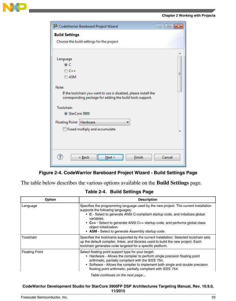
Figure 2-4. CodeWarrior Bareboard Project Wizard - Build Settings Page
The table below describes the various options available on the Build Settings page.
Table 2-4. Build Settings Page
Option Description
Language Specifies the programming language used by the new project. The current installationsupports the following languages:
• C - Select to generate ANSI C-compliant startup code, and initializes globalvariables.
• C++ - Select to generate ANSI C++ startup code, and performs global classobject initialization.
• ASM - Select to generate Assembly startup code.
Toolchain Specifies the toolchains supported by the current installation. Selected toolchain setsup the default compiler, linker, and libraries used to build the new project. Eachtoolchain generates code targeted for a specific platform.
Floating Point Select floating point support type for your target:• Hardware - Allows the compiler to perform single precision floating point
arithmetic, partially compliant with the IEEE 754.• Software - Allows the compiler to implement both single and double precision
floating point arithmetic, partially compliant with IEEE 754.
Table continues on the next page...
Chapter 2 Working with Projects
CodeWarrior Development Studio for StarCore 3900FP DSP Architectures Targeting Manual, Rev. 10.9.0,11/2015
Freescale Semiconductor, Inc. 33

Table 2-4. Build Settings Page (continued)
Option Description
Both hardware floating point and software floating point are supported on B4420,B4860, SC3900fp, and their derivatives. For more information on hardware andsoftware floating point support, see StarCore C/C++ Compiler User Guide.
Fused multiply and accumulate Enables fused multiply and add generation. Fused multiply and add are generated onlyif hardware floating point support is enabled on the SC3900fp compiler.
2.1.5 SmartDSP OS Page
Use this page to specify the SmartDSP OS support for your project.
Figure 2-5. CodeWarrior Bareboard Project Wizard - SmartDSP OS Page
Table 2-5. SmartDSP OS Page Settings
Option Description
SmartDSP OS Specifies the SmartDSP operating system support for yourproject.
• Yes-Select to create a project that supports SmartDSPOS.
• No-Select to create a project without SmartDSP OSsupport.
CodeWarrior Bareboard Project Wizard
CodeWarrior Development Studio for StarCore 3900FP DSP Architectures Targeting Manual, Rev. 10.9.0,11/2015
34 Freescale Semiconductor, Inc.

2.2 Creating projects
This section explains you how to use the CodeWarrior Bareboard Project Wizard toquickly create new projects with default settings (build and launch configurations).
This section explains:
• Creating CodeWarrior Bareboard Project
2.2.1 Creating CodeWarrior Bareboard Project
You can create a CodeWarrior bareboard application project using the CodeWarriorBareboard Project Wizard.
To create a CodeWarrior bareboard application project, perform these steps:
NOTEFor details about the options in the CodeWarrior BareboardProject wizard pages, see the topic CodeWarrior BareboardProject Wizard.
1. Select Start > All Programs > Freescale CodeWarrior > CW for StarCore3900FP vnumber > CodeWarrior IDE, where number is the version number ofyour product.
The Workspace Launcher dialog box appears, prompting you to select a workspaceto use.
NOTEClick Browse to change the default location for workspacefolder. You can also select the Use this as the default anddo not ask again checkbox to set default or selected path asthe default location for storing all your projects.
2. Click OK.
The default workspace is accepted. The CodeWarrior IDE launches and theWelcome page appears.
Chapter 2 Working with Projects
CodeWarrior Development Studio for StarCore 3900FP DSP Architectures Targeting Manual, Rev. 10.9.0,11/2015
Freescale Semiconductor, Inc. 35

NOTEThe Welcome page appears only if the CodeWarrior IDEor the selected workspace is started for the first time.Otherwise, the Workbench window appears.
3. Click Go to Workbench from the Welcome page.
The workbench window appears.
4. Select File > New > CodeWarrior Bareboard Project Wizard, from theCodeWarrior IDE menu bar.
The CodeWarrior Bareboard Project Wizard launches and the Create aCodeWarrior Bareboard Project page appears.
5. Specify a name for the new project in the Project name text box.
For example, enter the project name as Hello_World.
6. If you do not want to create your project in the default workspace:a. Clear the Use default location checkbox.b. Click Browse and select the desired location from the Browse For Folder
dialog box.c. In the Location text box, append the location with the name of the directory in
which you want to create your project. In the Location text box, append thelocation with the name of the directory in which you want to create your project.
NOTEAn existing directory cannot be specified for theproject location. If created, the CodeWarrior willprompt an error message.
7. Click Next.
The Processor page appears.
8. Select the target processor for the new project, from the Processor list.9. Select Application from the Project Output group, to create an application
with .elf extension, that includes information required to debug the project.10. Click Next.
The Debug Target Settings page appears.
11. Select a supported connection type (hardware, simulator, or emulator), from theDebugger Connection Types group. Your selection determines the launchconfigurations that you can include in your project.
12. Select the board you are targeting, from the Board drop-down list.
Creating projects
CodeWarrior Development Studio for StarCore 3900FP DSP Architectures Targeting Manual, Rev. 10.9.0,11/2015
36 Freescale Semiconductor, Inc.

13. Select the launch configurations that you want to include in your project and thecorresponding connection, from the Launch group.
NOTEFor more information on remote systems, see CodeWarriorDevelopment Studio Common Features Guide.
14. Select the interface to communicate with the hardware, from the Connection Typedrop-down list.
15. Enter the IP address of the TAP device in the TAP address text box. This option isavailable only if Ethernet TAP,CodeWarrior Ethernet TAP, or Gigabit TAP isselected as the connection type.
16. Click Next.
The Build Settings page appears.
17. Select the programming language, you want to use, from the Language group.
The language you select determines the libraries that are linked with your programand the contents of the main source file that the wizard generates.
NOTEIf you select C++, you can still add C source files to theproject and vice versa.
18. Select a toolchain from the Toolchain group.
Selected toolchain sets up the default compiler, linker, and libraries used to build thenew project. Each toolchain generates code targeted for a specific platform.
NOTEIf the toolchain you want to use is disabled, you have toinstall the corresponding Service Pack for adding the buildtools support.
19. Select an option from the Floating Point drop-down list, to prompt the compiler tohandle the floating-point operations by generating instructions for the selectedfloating-point unit.
20. Check the Fused multiple and accumulate checkbox to enable fused multiply and addgeneration.
NOTEFused multiply and add are generated only if hardwarefloating point support is enabled on the SC3900fpcompiler.
Chapter 2 Working with Projects
CodeWarrior Development Studio for StarCore 3900FP DSP Architectures Targeting Manual, Rev. 10.9.0,11/2015
Freescale Semiconductor, Inc. 37

NOTEFor more information on hardware and software floatingpoint support and fused multiply and accumulate, see theStarCore C/C++ Compiler User Guide.
21. Click Next.
The SmartDSP OS page appears.
22. Select Yes to create a project that supports SmartDSP OS.
NOTESmartDSP OS support is currently available for theQonverge targets only.
23. Click Finish.
The wizard creates an application project according to your specifications. You canaccess the project from the CodeWarrior Projects view on the Workbench.
The new project is ready for use. You can now customize the project by adding your ownsource code files, changing debugger settings and adding libraries.
2.3 Importing Projects
This section explains how to import existing projects, such as SmartDSP in StarCore.
• Importing SmartDSP OS Project
2.3.1 Importing SmartDSP OS Project
CodeWarrior Development Studio for StarCore 3900FP DSPs includes SmartDSP OS, apre-emptable, real-time, priority-based operating system, specially designed for high-performance DSPs operating with tight memory requirements.
NOTESmartDSP OS support must be installed as part of theCodeWarrior installation to be able to import and modify aSmartDSP OS project.
To import an existing sample SmartDSP OS project and customize it, follow these steps:
Importing Projects
CodeWarrior Development Studio for StarCore 3900FP DSP Architectures Targeting Manual, Rev. 10.9.0,11/2015
38 Freescale Semiconductor, Inc.
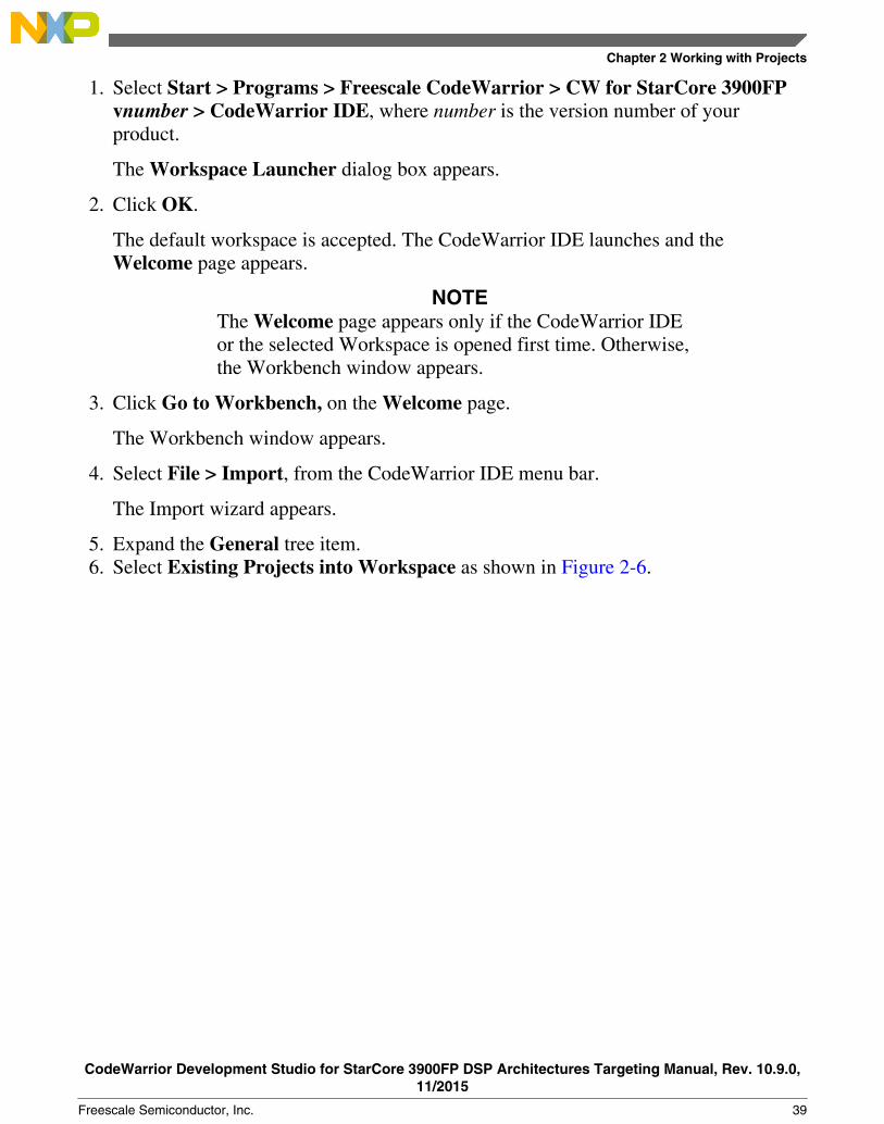
1. Select Start > Programs > Freescale CodeWarrior > CW for StarCore 3900FPvnumber > CodeWarrior IDE, where number is the version number of yourproduct.
The Workspace Launcher dialog box appears.
2. Click OK.
The default workspace is accepted. The CodeWarrior IDE launches and theWelcome page appears.
NOTEThe Welcome page appears only if the CodeWarrior IDEor the selected Workspace is opened first time. Otherwise,the Workbench window appears.
3. Click Go to Workbench, on the Welcome page.
The Workbench window appears.
4. Select File > Import, from the CodeWarrior IDE menu bar.
The Import wizard appears.
5. Expand the General tree item.6. Select Existing Projects into Workspace as shown in Figure 2-6.
Chapter 2 Working with Projects
CodeWarrior Development Studio for StarCore 3900FP DSP Architectures Targeting Manual, Rev. 10.9.0,11/2015
Freescale Semiconductor, Inc. 39

Figure 2-6. Import Wizard - Select Existing Projects into Workspace7. Click Next.
The Import Projects page appears.
8. Select the Select root directory option.
The wizard enables the corresponding Browse button.
NOTEThe Projects text box displays all the projects availableunder the selected directory.
9. Click Browse.
The Browse For Folder dialog box appears.
10. Use the dialog box to navigate to the SmartDSP OS demo project you want tomodify. For example, b4860\basic_demo\project.
Importing Projects
CodeWarrior Development Studio for StarCore 3900FP DSP Architectures Targeting Manual, Rev. 10.9.0,11/2015
40 Freescale Semiconductor, Inc.

NOTEThe SmartDSP OS demo projects are available in the<CWInstallDir>\SC\StarCore_Support\SmartDSP\demos\starcore
\<platform> folder, where <CWInstallDir> is the path to yourCodeWarrior installation.
11. Click OK.
The Browse For Folder dialog box closes. The path to the demo project appears inthe Select root directory text box (Figure 2-7).
Figure 2-7. Import Wizard - Import Existing Projects12. Ensure that the project you want to import is selected.13. Click Finish.
The Import wizard closes and the C/C++ perspective appears.
The CodeWarrior Projects view shows the selected SmartDSP OS project.
NOTETo make your own project, rename the demo projectdirectory and copy it to the <CWInstallDir>\SC
Chapter 2 Working with Projects
CodeWarrior Development Studio for StarCore 3900FP DSP Architectures Targeting Manual, Rev. 10.9.0,11/2015
Freescale Semiconductor, Inc. 41

\StarCore_Support\SmartDSP\demos\starcore\<platform> folder.The projects in the renamed directory work because allproject access paths are relative.
14. In the CodeWarrior Projects view, select the project to configure the buildproperties.
15. Select Project >Properties.
The Properties for <project> dialog box appears. The left side of this dialog boxhas a Properties list. This list shows the properties that apply to the selected project.
16. Expand the C/C++ Build property.17. Select Settings.18. Use the Configuration drop-down list to select the launch configuration for which
you want to modify the build properties.19. Click the Tool Settings tab.
The corresponding page appears.
20. From the list of tools on the Tool Settings page, expand the StarCore 3900 C/C++Linker Application tree item.
21. The library build configuration options panel appears.
If you want to change these options, see the chapter Libraries.
Importing Projects
CodeWarrior Development Studio for StarCore 3900FP DSP Architectures Targeting Manual, Rev. 10.9.0,11/2015
42 Freescale Semiconductor, Inc.

Figure 2-8. CodeWarrior Projects-Demo SmartDSP OS Project22. Click Apply.23. Click OK.
The Properties for <project> dialog box closes.
You just finished importing a sample SmartDSP OS project.
2.4 Building projects
CodeWarrior IDE supports two modes of building projects, manual-build mode and auto-build mode.
2.4.1 Manual-Build mode
Chapter 2 Working with Projects
CodeWarrior Development Studio for StarCore 3900FP DSP Architectures Targeting Manual, Rev. 10.9.0,11/2015
Freescale Semiconductor, Inc. 43

In large workspaces, building the entire workspace can take a long time if users makechanges with a significant impact on dependent projects. Often there are only a fewprojects that really matter to a user at a given time.
To build only the selected projects, and any prerequisite projects that need to be built tocorrectly build the selected projects, select Project > Build Project from theCodeWarrior IDE menu bar.
Figure 2-9. Project Menu- Build Project
Alternatively, right-click on the selected project in the CodeWarrior Projects view andselect Build Project from the context menu.
Figure 2-10. Context Menu-Build Project
Building projects
CodeWarrior Development Studio for StarCore 3900FP DSP Architectures Targeting Manual, Rev. 10.9.0,11/2015
44 Freescale Semiconductor, Inc.
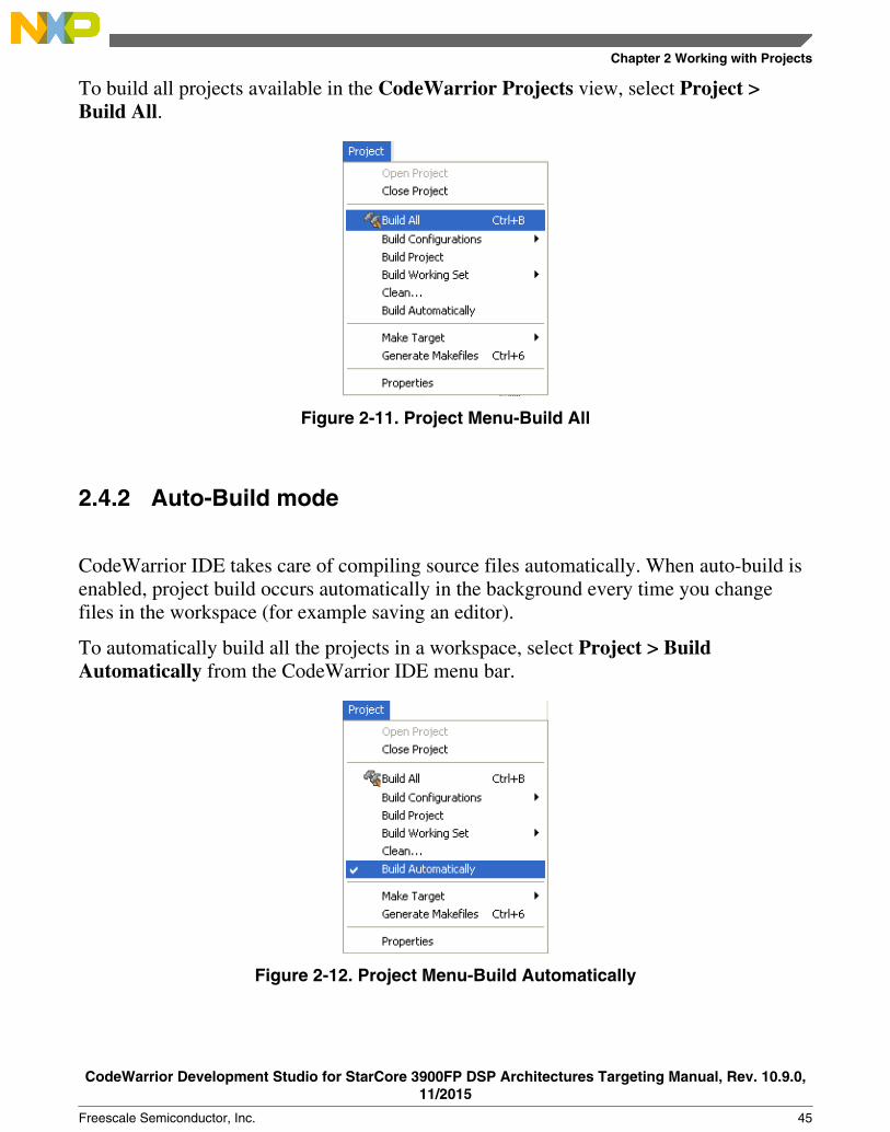
To build all projects available in the CodeWarrior Projects view, select Project >Build All.
Figure 2-11. Project Menu-Build All
2.4.2 Auto-Build mode
CodeWarrior IDE takes care of compiling source files automatically. When auto-build isenabled, project build occurs automatically in the background every time you changefiles in the workspace (for example saving an editor).
To automatically build all the projects in a workspace, select Project > BuildAutomatically from the CodeWarrior IDE menu bar.
Figure 2-12. Project Menu-Build Automatically
Chapter 2 Working with Projects
CodeWarrior Development Studio for StarCore 3900FP DSP Architectures Targeting Manual, Rev. 10.9.0,11/2015
Freescale Semiconductor, Inc. 45

If auto-build is taking too long and is interfering with ongoing development, it can beturned off. Select Project > Build Automatically from the CodeWarrior IDE menu barto disable auto-build mode.
NOTEIt is advised that you do not use the Build Automaticallyoption for C/C++ development. Using this option will result inbuilding the entire project whenever you save a change to themakefile or source files. This can take a significant amount oftime for very large projects.
2.5 Deleting Projects
Using the options available in CodeWarrior IDE, you can delete a project and optionallythe resources linked to the project.
To delete a project, follow these steps:
1. Select the project you want to delete in the CodeWarrior Projects view.2. Select Edit > Delete.
The Delete Resources dialog box appears.
NOTEAlternatively, you can also select Delete from the contextmenu that appears when you right-click the project.
3. Select the Delete project contents on disk (cannot be undone) option to delete theproject contents permanently.
NOTEYou will not be able to restore your project using Undo, ifyou select the Delete project contents on disk (cannot beundone) option.
4. Click OK.
The selected project is deleted and relevant details of the project are removed from theCodeWarrior Projects view.
Deleting Projects
CodeWarrior Development Studio for StarCore 3900FP DSP Architectures Targeting Manual, Rev. 10.9.0,11/2015
46 Freescale Semiconductor, Inc.
Chapter 3Build Properties
This chapter explains build properties for StarCore projects. A project can containmultiple build and launch configurations.
A build configuration is a named collection of build tools options. The set of options in agiven build configuration causes the build tools to generate a final binary with specificcharacteristics. For example, the binary produced by a Debug build configuration mightcontain symbolic debugging information and have no optimizations, while the binaryproduct by a Release build configuration might contain no symbolics and be highlyoptimized.
NOTEThe settings of the CodeWarrior IDE's build and launchconfiguration correspond to an object called a target made bythe classic CodeWarrior IDE.
This chapter explains:
• Changing Build Properties• Restoring Build Properties• Build Properties for StarCore
3.1 Changing Build Properties
You can modify the build properties of a project to better suit your needs.
Follow these steps to change build properties:
1. Start the CodeWarrior IDE.2. In the CodeWarrior Projects view, select the project for which you want to modify
the build properties.
CodeWarrior Development Studio for StarCore 3900FP DSP Architectures Targeting Manual, Rev. 10.9.0,11/2015
Freescale Semiconductor, Inc. 47

3. Select Project > Properties.
The Properties for <project> dialog box appears. The left side of this window has aProperties list. This list shows the build properties that apply to the current project.
4. Expand the C/C++ Build property node.5. Select Settings.6. Use the Configuration drop-down list to specify the launch configuration for which
you want to modify the build properties.7. Click the Tool Settings tab. The corresponding page appears.8. From the list of tools on the Tool Settings page, select the tool for which you want to
modify properties.9. Change the settings as per the requirements.
10. Click Apply.
The CodeWarrior IDE saves your new settings.
You can select other tool pages and modify their settings. When you finish, click OK tosave your changes and close the Properties for <project> dialog box.
3.2 Restoring Build Properties
You can modify a build configuration of a project and restore it back in order to have afactory-default configuration, or to revert to a last-known working build configuration.
To undo your modifications to build properties, click the Restore Defaults button at thebottom of the Properties for<project> dialog box.
This changes the values of the options to the absolute default of the toolchain. By default,the toolchain options are blank.
3.3 Build Properties for StarCore
The Properties for <project> dialog box shows the corresponding build properties for aStarCore project.
Restoring Build Properties
CodeWarrior Development Studio for StarCore 3900FP DSP Architectures Targeting Manual, Rev. 10.9.0,11/2015
48 Freescale Semiconductor, Inc.

Figure 3-1. Properties for <Project> Dialog Box
Table 3-1 lists the build tool settings specific to developing software for StarCore.
Table 3-1. Build Tool Settings for StarCore
Build Tool Build Properties Panels
StarCore Environment
StarCore 3900 Disassembler Disassembler Settings
StarCore 3900 C/C++ Linker Application Linker Settings
C/C++ Options
Libraries
StarCore 3900 C/C++ Compiler C/C++ Language
Control
Hardware Configuration
Output Listing
Warnings
Compiler Front End Messages
Assembler
Table continues on the next page...
Chapter 3 Build Properties
CodeWarrior Development Studio for StarCore 3900FP DSP Architectures Targeting Manual, Rev. 10.9.0,11/2015
Freescale Semiconductor, Inc. 49

Table 3-1. Build Tool Settings for StarCore (continued)
Build Tool Build Properties Panels
Linker
Include Search Paths
Macros
Processor
Optimization
Configuration Files
Additional Arguments
StarCore 3900 Assembler Code and Language Options
Include Search Paths
Preprocessor
Listing File
Listing Contents
Listing Format
Additional Arguments
StarCore 3900 Preprocessor Preprocessor Settings
The CodeWarrior build tools listed in Table 3-1 share some properties panels, such as theInclude Search Paths. The properties that you specify in these panels apply to theselected build tool on the Tool Settings page of the Properties for <project> dialog box.
3.3.1 StarCore Environment
Use this panel to specify the StarCore architecture for the build and the memory modelthat the architecture uses.
The build tools (compiler, linker, and assembler) use the properties that you specify onthis page.
Build Properties for StarCore
CodeWarrior Development Studio for StarCore 3900FP DSP Architectures Targeting Manual, Rev. 10.9.0,11/2015
50 Freescale Semiconductor, Inc.

Figure 3-2. Tool Settings - StarCore Environment
Table 3-2 describes the various options available on the StarCore Environment panel.
Table 3-2. Tool Settings - StarCore Environment Options
Option Description
Architecture Specify the StarCore architecture for which you build yourproject.
Memory Model Specify the memory model for the build tools:• Small Memory Model-absolute addresses fit in 64KB• Big Memory Model-absolute addresses do not fit in
64KB, but fit in 1MB• Big Memory Model w/ Far RT Lib Calls-Absolute
addresses do not fit in 64KB, but fit in 1MB. The buildtools make runtime-library calls in the same mannerthey do for the huge memory model.
• Huge Memory Model-absolute addresses do not fit in1MB
Table continues on the next page...
Chapter 3 Build Properties
CodeWarrior Development Studio for StarCore 3900FP DSP Architectures Targeting Manual, Rev. 10.9.0,11/2015
Freescale Semiconductor, Inc. 51

Table 3-2. Tool Settings - StarCore Environment Options (continued)
Option Description
Force C++ Compilation Checked -Enforce C++ compilation for the files that do nothave the .cpp extension. This setting is equivalent tospecifying the -force c++ command-line option. Cleared -C++ compilation is not enforced for the files that do not havethe .cpp extension.
Floating Point Specify floating point type for the project, Hardware orSoftware. Both hardware floating point and software floatingpoint are supported on B4420, B4860, SC3900fp, and theirderivatives.
3.3.2 StarCore 3900 Disassembler
Use this panel to specify the command, options, and expert settings for the StarCore 3900disassembler.
Figure 3-3. Tool Settings - StarCore 3900 Disassembler
Build Properties for StarCore
CodeWarrior Development Studio for StarCore 3900FP DSP Architectures Targeting Manual, Rev. 10.9.0,11/2015
52 Freescale Semiconductor, Inc.

Table 3-3 describes the various options available on the StarCore 3900 Disassemblerpanel.
Table 3-3. Tool Settings - StarCore 3900 Disassembler Options
Option Description
Command Shows the location of the disassembler executable file.
All options Shows the actual command line the disassembler will becalled with.
Expert Settings:
Command line pattern
Shows the expert settings command line parameters; defaultis "${SCToolsInstallDir}${COMMAND}" ${FLAGS} ${INPUTS}.
3.3.2.1 Disassembler Settings
Use this panel to specify the Disassembler behavior.
Figure 3-4. Tool Settings - Disassembler Settings
Chapter 3 Build Properties
CodeWarrior Development Studio for StarCore 3900FP DSP Architectures Targeting Manual, Rev. 10.9.0,11/2015
Freescale Semiconductor, Inc. 53

Table 3-4 describes the various options available on the Disassembler Settings panel.
Table 3-4. Tool Settings - Disassembler Settings Options
Option Description
Compact Specifies compact output mode.
Checked - The disassembler prints instructions in anexecution -set on a single line.
Cleared - The disassembler does not print instructions in anexecution -set on a single line.
Start Label Specifies the label at which disassembly of the input filestarts.
End Label Specifies the label at which disassembly of the input file ends.
Start Address (Hex) Specifies the hexadecimal address at which the disassemblystarts.
End Address (Hex) Specifies the hexadecimal address at which the disassemblyends.
Print loopstart - loopend Checked - The disassembler prints loopstart-loopenddirectives.
Cleared - The disassembler prints lpmarka/lpmarkbdirectives.
Suppress Banner Checked - The disassembler suppresses display of bannerinformation.
Cleared - The disassembler does not suppress bannerdisplay.
Ignore Relocation Information Checked - The disassembler ignores the relocationinformation relevant to .eln and .elb files.
Cleared - Disassembler does not ignore the relocationinformation.
Display Unmangled C++ Names Checked - The disassembler displays unmangled form of C++ names.
Cleared - The disassembler does not display unmangled formof C++ names.
Suppress PC Checked - The disassembler suppresses the PC display forVLES.
Cleared - The disassembler does not supress the PC displayfor VLES.
Suppress Label and Header Checked - The disassembler suppresses display of labels,headers, and global information ( equs, globals, andsection information).
Cleared - The disassembler does not supress display oflabels and header information.
Display Mixed Hexadecimal and Assembly Checked - The disassembler displays mixed hexadecimalcodification and assembly code. Cleared - The disassemblerdoes not display mixed hexadecimal codification andassembly code.
Verbose Checked - Enables verbose mode.
Cleared - Does not enable verbose mode.
Table continues on the next page...
Build Properties for StarCore
CodeWarrior Development Studio for StarCore 3900FP DSP Architectures Targeting Manual, Rev. 10.9.0,11/2015
54 Freescale Semiconductor, Inc.

Table 3-4. Tool Settings - Disassembler Settings Options (continued)
Option Description
Display Statistics Checked - The disassembler displays statistics after eachsection, which includes but not limited to: number of VLESwith 0 - 4 DALU instructions, number of VLES with 0 - 2AGU instructions, not-generated instructions.
Cleared - The disassembler does not display statistics aftereach section.
3.3.3 StarCore 3900 C/C++ Linker Application
Use this panel to specify the command, options, and expert settings for the build toollinker.
Figure 3-5. Tool Settings - StarCore 3900 C/C++ Linker Application
Chapter 3 Build Properties
CodeWarrior Development Studio for StarCore 3900FP DSP Architectures Targeting Manual, Rev. 10.9.0,11/2015
Freescale Semiconductor, Inc. 55

Table 3-5 describes the various options available on the StarCore 3900 C/C++ LinkerApplication panel.
Table 3-5. Tool Settings - StarCore 3900 C/C++ Linker Application Options
Option Description
Command Shows the location of the linker executable file.
All options Shows the actual command line the linker will be called with.
Expert Settings
Command line pattern
Shows the expert settings command line parameters; defaultis "${SCToolsInstallDir}${COMMAND}" ${FLAGS} ${OUTPUT_FLAG} ${OUTPUT_PREFIX}${OUTPUT} ${INPUTS}.
3.3.3.1 Linker Settings
Use this panel to specify the linker behavior.
For C and C++ source files, build tools optimize the output object code. The build toolsdo not optimize hand-coded assembly language.
Figure 3-6. Tool Settings - Linker Settings
Build Properties for StarCore
CodeWarrior Development Studio for StarCore 3900FP DSP Architectures Targeting Manual, Rev. 10.9.0,11/2015
56 Freescale Semiconductor, Inc.

Table 3-6 describes the various options available on the Linker Settings panel.
Table 3-6. Tool Settings - Linker Settings Options
Option Description
Map File Enter the path of the file to which the linker writes memory-map information. This filename must have a .map extension.
Strip Dead Code Checked - The linker removes both unreferenced sourcecode and unreferenced data from your program. Enabling thisoption reduces your program's memory footprint.
Cleared - The linker preserves both unreferenced sourcecode and unreferenced data in your program.
Linker Command File Enter the path of the linker-command file that the build toolsuse for processing your project. Alternatively, click theBrowse button, then use the resulting dialog box to specifythe linker command file.
Additional Options Enter additional linker command-line options. The IDE passesthese options to the scc shell during the link phase. Note thatthe IDE passes command-line options to the scc shell exactlyas you enter them in this text box.
3.3.3.2 C/C++ Options
Use this panel to specify linker behavior.
For C and C++ source files, the build tools optimize output object code. The build toolsdo not optimize hand-coded assembly language.
Chapter 3 Build Properties
CodeWarrior Development Studio for StarCore 3900FP DSP Architectures Targeting Manual, Rev. 10.9.0,11/2015
Freescale Semiconductor, Inc. 57

Figure 3-7. Tool Settings - C/C++ Options
Table 3-7 describes the various options available on the C/C++ Options panel.
Table 3-7. Tool Settings - C/C++ Options
Option Description
Use Re-entrant Runtime Libraries Checked - The linker uses the correct thread-safe librariesand start-up code for your target architecture. If checked, theIDE passes -reentrant to the scc shell.
Cleared - The linker uses default libraries and startup code.
Custom Start-Up File Enter the path to a custom start-up file that the linker usesinstead of a default start-up file. Alternatively, click the Browsebutton, then use the resulting dialog box to specify the customstart-up file. Leave this text box blank to have the linker use adefault start-up file.
3.3.3.3 Libraries
Use this panel to specify additional libraries that the StarCore C/C++ Linker should use.
You can specify multiple additional libraries and library search paths. Also, you canchange the order in which the IDE uses or searches the libraries.
Build Properties for StarCore
CodeWarrior Development Studio for StarCore 3900FP DSP Architectures Targeting Manual, Rev. 10.9.0,11/2015
58 Freescale Semiconductor, Inc.

Figure 3-8. Tool Settings - Libraries
Table 3-8 describes the various options available on the Libraries panel.
Table 3-8. Tool Settings - Libraries
Option Description
Additional Libraries Lists paths to additional libraries that the StarCore C/C++linker uses. The linker uses the libraries in the order shown inthis list.
Library Search Paths Lists paths that the StarCore C/C++ linker searches forlibraries. The linker searches the paths in the order shown inthis list.
Table 3-9 lists and describes the toolbar buttons that help work with the libraries.
Table 3-9. Tool Settings - Libraries Toolbar Buttons
Button Description
Add - Click to open the Add file path or the Add directorypath dialog box and create a file or directory path.
Delete - Click to delete the selected file or directory. Toconfirm deletion, click Yes in the Confirm Delete dialog box.
Edit - Click to open the Edit file path or Edit directory pathdialog box and update the selected file or directory.
Table continues on the next page...
Chapter 3 Build Properties
CodeWarrior Development Studio for StarCore 3900FP DSP Architectures Targeting Manual, Rev. 10.9.0,11/2015
Freescale Semiconductor, Inc. 59

Table 3-9. Tool Settings - Libraries Toolbar Buttons (continued)
Button Description
Move up - Click to move the selected file search path oneposition higher in the list.
Move down - Click to move the selected file search path oneposition lower in the list.
3.3.4 StarCore 3900 C/C++ Compiler
Use this panel to specify the command, options, and expert settings for the build toolcompiler.
Figure 3-9. Tool Settings - StarCore 3900 C/C++ Compiler
Build Properties for StarCore
CodeWarrior Development Studio for StarCore 3900FP DSP Architectures Targeting Manual, Rev. 10.9.0,11/2015
60 Freescale Semiconductor, Inc.
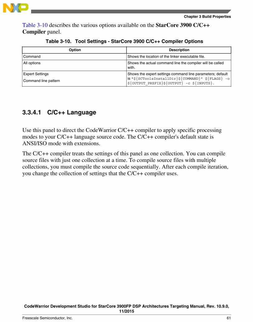
Table 3-10 describes the various options available on the StarCore 3900 C/C++Compiler panel.
Table 3-10. Tool Settings - StarCore 3900 C/C++ Compiler Options
Option Description
Command Shows the location of the linker executable file.
All options Shows the actual command line the compiler will be calledwith.
Expert Settings
Command line pattern
Shows the expert settings command line parameters; defaultis "${SCToolsInstallDir}${COMMAND}" ${FLAGS} -o${OUTPUT_PREFIX}${OUTPUT} -c ${INPUTS}.
3.3.4.1 C/C++ Language
Use this panel to direct the CodeWarrior C/C++ compiler to apply specific processingmodes to your C/C++ language source code. The C/C++ compiler's default state isANSI/ISO mode with extensions.
The C/C++ compiler treats the settings of this panel as one collection. You can compilesource files with just one collection at a time. To compile source files with multiplecollections, you must compile the source code sequentially. After each compile iteration,you change the collection of settings that the C/C++ compiler uses.
Chapter 3 Build Properties
CodeWarrior Development Studio for StarCore 3900FP DSP Architectures Targeting Manual, Rev. 10.9.0,11/2015
Freescale Semiconductor, Inc. 61

Figure 3-10. Tool Settings - C/C++ Language
Table 3-11 describes the various options available on the C/C++ Language panel.
Table 3-11. Tool Settings - C/C++ Language Options
Option Description
Strict ANSI mode Checked - The C/C++ compiler operates in strict ANSI mode.In this mode, the compiler strictly applies the rules of theANSI/ISO specification to all input files. This setting isequivalent to specifying the - ansi command-line option.The compiler issues a warning for each ANSI/ISO extension itfinds.
Cleared - The C/C++ compiler does not operate in strict ANSImode.
Type 'char' is signed Checked - The C/C++ compiler treats all char data types assigned. This setting is the default.
Cleared - The C/C++ compiler treats all char data types asunsigned (as if you had declared them unsigned char).This setting is equivalent to specifying the -usc commandline option.
64-Bit Data Type Support Checked - The C/C++ compiler supports 64-bit data typeslong long and double. A long long is a 64-bit integer. Adouble is a 64-bit double-precision floating-point value.
Cleared - The C/C++ compiler does not support data typeslong long and double.
Build Properties for StarCore
CodeWarrior Development Studio for StarCore 3900FP DSP Architectures Targeting Manual, Rev. 10.9.0,11/2015
62 Freescale Semiconductor, Inc.

3.3.4.2 Control
Use this panel to control compiler and shell behavior. You can specify command-lineoptions to pass to the compiler and whether to generate debugging information.
Figure 3-11. Tool Settings - Control
Table 3-12 describes the various options available on the Control panel.
Table 3-12. Tool Settings - Control Options
Options Description
Read Options from File Enter the path to a file that contains compiler command-lineoptions. Alternatively, click Browse and use the resultingdialog box to specify the file. This setting is equivalent tospecifying the -F file command-line option. The filename mustuse the .opt extension. The shell treats the options in thisfile as if you had passed them on the command line. Each
Table continues on the next page...
Chapter 3 Build Properties
CodeWarrior Development Studio for StarCore 3900FP DSP Architectures Targeting Manual, Rev. 10.9.0,11/2015
Freescale Semiconductor, Inc. 63

Table 3-12. Tool Settings - Control Options (continued)
Options Description
time you invoke the compiler, you can select a file with the setof options that suits your needs. Note that the IDE does notverify the validity of the options in the file.
Generate Debugging Information Checked - The compiler produces symbolic information fordebugging the build target.
Cleared - The compiler does not produce symbolicinformation.
3.3.4.3 Hardware Configuration
Use this panel to control how the compiler structures generated object code. You canspecify whether to initialize variables from read-only memory (ROM).
Figure 3-12. Tool Settings - Hardware Configuration
Build Properties for StarCore
CodeWarrior Development Studio for StarCore 3900FP DSP Architectures Targeting Manual, Rev. 10.9.0,11/2015
64 Freescale Semiconductor, Inc.

Table 3-13 describes the various options available on the Hardware Configuration panel.
Table 3-13. Tool Settings - Hardware Configuration Options
Option Description
Initialize Variables from ROM Checked - The compiler places the initialization data for yourprogram's global variables in a separate section. This settingis equivalent to specifying the -mrom command-line option.The IDE can manipulate the section at link time and at loadtime.
Cleared - The compiler bypasses placing the initializationdata for your program's global variables in a separate section.You can clear this checkbox as you develop your sourcecode, because a separate loader program handles initializingyour program's global variables. After you finish development,you can check this checkbox, then place into ROM thesegment with the initialization data for your global variables.
3.3.4.4 Output Listing
Use this panel to control how the compiler formats the listing file, as well as error andwarning messages.
Chapter 3 Build Properties
CodeWarrior Development Studio for StarCore 3900FP DSP Architectures Targeting Manual, Rev. 10.9.0,11/2015
Freescale Semiconductor, Inc. 65

Figure 3-13. Tool Settings - Output Listing
Table 3-14 describes the various options available on the Output Listing panel.
Table 3-14. Tool Settings - Output Listing Options
Option Description
Verbosity Specify the amount of information that the compilergenerates:
• Quiet - The IDE displays just error messages that thecompiler emits. The IDE suppresses warning andinformational messages. This setting is equivalent tospecifying the -q command-line option.
• Default - The IDE chooses whether to use Quiet orVerbose.
• Verbose - The IDE shows each command line that itpasses to the shell, along with all progress, error,warning, and informational messages that the toolsemit. This setting is equivalent to specifying the -vcommand-line option.
Create File with Error Output Checked - The IDE generates a file that contains errormessages that the compiler outputs.
Cleared - The IDE does not generate a file that contains errormessages.
Table continues on the next page...
Build Properties for StarCore
CodeWarrior Development Studio for StarCore 3900FP DSP Architectures Targeting Manual, Rev. 10.9.0,11/2015
66 Freescale Semiconductor, Inc.

Table 3-14. Tool Settings - Output Listing Options (continued)
Option Description
Keep assembly (.sl) files Checked - The compiler keeps the intermediate assembly-language source files ( .sl files) it creates, instead ofdeleting them. This setting is equivalent to specifying the -scommand-line option. The compiler generates one .sl file foreach C source file in the build target.
Cleared - The compiler discards the intermediate assembly-language source files it creates.
Define Struct Fd Offsets as EQUs Checked - The compiler includes the offsets of C data-structure field definitions in each generated intermediateassembly-language source file. This setting is equivalent tospecifying the - do command-line option.
Cleared - The compiler does not include the offsets of C data-structure field definitions in each generated intermediateassembly-language source file.
3.3.4.5 Warnings
Use this panel to control how the compiler reports the error and warning messages.
Figure 3-14. Tool Settings - Warnings
Chapter 3 Build Properties
CodeWarrior Development Studio for StarCore 3900FP DSP Architectures Targeting Manual, Rev. 10.9.0,11/2015
Freescale Semiconductor, Inc. 67

Table 3-15 describes the various options available on the Warning panel.
Table 3-15. Tool Settings - Warning Options
Option Description
Report All Warnings Specifies global remark/warning control. This setting isequivalent to specifying the -W command-line option.
Generate Wrapper Remarks Checked-The IDE generates a file that contains Wrapperremarks that the compiler outputs. Cleared-The IDE does notgenerate a file that contains Wrapper remarks.
Generate Wrapper Warnings Checked-The IDE generates a file that contains Wrapperwarnings that the compiler outputs. Cleared-The IDE does notgenerate a file that contains Wrapper remarks.
3.3.4.5.1 Compiler Front End Messages
Use this panel to control how the compiler generates compiler-front-end warnings.
Figure 3-15. Tool Settings - Compiler Front End Messages
Build Properties for StarCore
CodeWarrior Development Studio for StarCore 3900FP DSP Architectures Targeting Manual, Rev. 10.9.0,11/2015
68 Freescale Semiconductor, Inc.

Table 3-16 describes the various options available on the Compiler Front EndMessages panel.
Table 3-16. Tool Settings - Compiler Front End Messages Options
Option Description
Report All Compiler Front End Warnings Specifies global Compiler Front End warning control. Thissetting is equivalent to specifying the -Wmwfe or -Wnomwfecommand-line options.
Treat Warnings As Errors Activates or deactivates treatment of compiler-front-endwarnings as errors.
Any Pointer-to-Integer Conversions Activates or deactivates generation of warnings about anypointer-to-integer conversions. This setting is equivalent tospecifying the -Wmwfe-anyptrintconv or -Wnomwfe-anyptrintconv command-line options.
Lossy Pointer-to- Integer Conversions Activates or deactivates generation of warnings about lossypointer-to-integer conversions.
Command-Line Driver/Parser Warnings Activates or deactivates generation of command-line driver/parser warnings. This setting is equivalent to specifying the -Wmwfe-cmdline or -Wnomwfe-cmdline command-lineoptions.
Extra Commas Activates or deactivates generation of warnings about extracommas. This setting is equivalent to specifying the -Wmwfe-comma or -Wnomwfe-comma command-line options.
Display List of Active Warnings Activates or deactivates display of archive warnings list. Thissetting is equivalent to specifying the -Wmwfe-display or -Wnomwfe-display command-line options.
Empty Declarations Activates or deactivates generation of warnings about emptydeclarations. This setting is equivalent to specifying the -Wmwfe-emptydecl or -Wnomwfe-emptydecl command-line options.
Pedantic Error Checking Activates or deactivates pedantic error checking. This settingis equivalent to specifying the -Wmwfe-pedantic or -Wnomwfe-pedantic command-line options.
Incorrect Capitalization In #include "...." Activates or deactivates generation of warnings aboutincorrect capitalization in #include "...". This setting isequivalent to specifying the -Wmwfe-filecaps or -Wnomwfe-filecaps command-line options.
Incorrect Capitalization In #include <....> Activates or deactivates generation of warnings aboutincorrect capitalization in #include <...>. This setting isequivalent to specifying the -Wmwfe-sysfilecaps or -Wnomwfe-sysfilecaps command-line options.
Hidden Virtual Functions Activates or deactivates generation of warnings about hiddenvirtual functions. This setting is equivalent to specifying the -Wmwfe-hidenvirtual or -Wnomwfe-hidevirtualcommand-line options.
Invalid Pragmas Activates or deactivates generation of warnings about invalidpragmas. This setting is equivalent to specifying the -Wmwfe-illpragmas or -Wnomwfe-illpragmas command-lineoptions.
Table continues on the next page...
Chapter 3 Build Properties
CodeWarrior Development Studio for StarCore 3900FP DSP Architectures Targeting Manual, Rev. 10.9.0,11/2015
Freescale Semiconductor, Inc. 69

Table 3-16. Tool Settings - Compiler Front End Messages Options (continued)
Option Description
Implicit Integer-to-Floating-Point or Floating-Point-to-IntegerConversions
Activates or deactivates generation of warnings about implicitinteger-to-floating-point or floating-point-to-integerconversions. This setting is equivalent to specifying the -Wmwfe-implicitconv(or -Wmwfe-implicit) or -Wnomwfe-implicitconv(or -Wnomwfe-implicit)command-line options.
Implicit Floating-Point-to-Integer Conversions Activates or deactivates generation of warnings about implicitfloating-point-to-integer conversions. This setting is equivalentto specifying the -Wmwfe-float2int or -Wnomwfe-float2int command-line options.
Implicit Integer-to-Floating-Point Conversions Activates or deactivates generation of warnings about implicitinteger-to-floating-point conversions. This setting is equivalentto specifying the -Wmwfe-int2float or -Wnomwfe-int2float command-line options.
Implicit Signed/Unsigned Conversions Activates or deactivates generation of warnings about implicitsigned/unsigned conversions. This setting is equivalent tospecifying the -Wmwfe-impl_signedunsigned or -Wnomwfe-impl_signedunsigned command-line options.
Passing Large Arguments to Unprototyped Functions Activates or deactivates generation of warnings about passinglarge arguments to unprototyped functions. This setting isequivalent to specifying the -Wmwfe-largeargs or -Wnomwfe-largeargs command-line options.
Returning Without Values in Non-Void-Returning Function Activates or deactivates generation of warnings about returnswithout values in non-void-returning functions. This setting isequivalent to specifying the -Wmwfe-missingreturn or -Wnomwfe-missingreturn command-line options.
`inline' Functions Not Inlined Activates or deactivates generation of warnings about `inline'functions not inlined. This setting is equivalent to specifyingthe -Wmwfe-notinlined or -Wnomwfe-notinlinedcommand-line options.
Result of Non-Void-Returning Function Not Being Used Activates or deactivates generation of warnings about resultof non-void-returning function not being used. This setting isequivalent to specifying the -Wmwfe-notused or -Wnomwfe-notused command-line options.
Padding Added Between Struct Members Activates or deactivates generation of warnings aboutpadding added between struct members. This setting isequivalent to specifying the -Wmwfe-padding or -Wnomwfe-padding command-line options.
Possible Unwanted Side Effects Activates or deactivates generation of warnings aboutpadding added between struct members. This setting isequivalent to specifying the -Wmwfe-padding or -Wnomwfe-padding command-line options.
Inconsistent Use of Class and Struct Activates or deactivates generation of warnings aboutinconsistent use of class and struct. This setting is equivalentto specifying the -Wmwfe-structclass or -Wnomwfe-structclass command-line options.
Tokens Not Formed By The ## Operator Activates or deactivates generation of warnings about tokensnot formed by the ## operator. This setting is equivalent tospecifying the -Wmwfe-tokenpasting or -Wnomwfe-tokenpasting command-line options.
Table continues on the next page...
Build Properties for StarCore
CodeWarrior Development Studio for StarCore 3900FP DSP Architectures Targeting Manual, Rev. 10.9.0,11/2015
70 Freescale Semiconductor, Inc.

Table 3-16. Tool Settings - Compiler Front End Messages Options (continued)
Option Description
Undefined Macros In #if/#else Conditionals Activates or deactivates generation of warnings aboutundefined macros in #if/#else conditionals. This setting isequivalent to specifying the -Wmwfe--undefmacro (or -Wmwfe-undef) or -Wnomwfe-undefmacro (or -Wnomwfe-undef) command-line options.
Unused Variables Activates or deactivates generation of warnings about unusedvariables. This setting is equivalent to specifying the -Wmwfe-unusedvar or -Wnomwfe-unusedvar command-lineoptions.
Unused Arguments Activates or deactivates generation of warnings about unusedarguments. This setting is equivalent to specifying the -Wmwfe-unusedarg or -Wnomwfe-unusedarg command-line options.
Using Expressions As Statements Without Side Effects Activates or deactivates generation of warnings about usingexpressions as statements without side effects. This setting isequivalent to specifying the -Wmwfe-unusedexpr or -Wnomwfe-unusedexpr command-line options.
Overriding Function Has No `virtual' Keyword Activates or deactivates generation of warnings aboutoverriding function that has no `virtual' keyword.
Variables Uninitialized Before Used Activates or deactivates generation of warnings aboutvariables uninitialized before used. This setting is equivalentto specifying the -Wmwfe-unused or -Wnomwfe-unusedcommand-line options.
Hidden Local Variables Activates or deactivates generation of warnings about hiddenlocal variables. This setting is equivalent to specifying the -Wmwfe-hidden or -Wnomwfe-hidden command-lineoptions.
Missing Enum Case Labels Activates or deactivates generation of warnings about missingEnum case labels.
3.3.4.5.2 Assembler
Use this panel to control how the compiler generates FALIGN, assembler remarks andwarnings.
Chapter 3 Build Properties
CodeWarrior Development Studio for StarCore 3900FP DSP Architectures Targeting Manual, Rev. 10.9.0,11/2015
Freescale Semiconductor, Inc. 71

Figure 3-16. Tool Settings - Assembler
Table 3-17 describes the various options available on the Assembler panel.
Table 3-17. Tool Settings - Assembler Options
Option Description
All Assembler warnings Specifies global Assembler warning control. This setting isequivalent to specifying the -Wasm or -Wnoasm command-line options.
FALIGN Remarks Activates or deactivates generation of FALIGN remarks. Thissetting is equivalent to specifying the -Wasm-falign or -Wnoasm-falign command-line options.
Assembler Remarks Activates or deactivates generation of assembler remarks.This setting is equivalent to specifying the -Wasm-remarksor -Wnoasm-remarks command-line options.
Assembler Warnings Activates or deactivates generation of assembler warnings.This setting is equivalent to specifying the -Wasm-warningsor -Wnoasm-warnings command-line options.
3.3.4.5.3 Linker
Use this panel to control how the compiler generates all linker warnings.
Build Properties for StarCore
CodeWarrior Development Studio for StarCore 3900FP DSP Architectures Targeting Manual, Rev. 10.9.0,11/2015
72 Freescale Semiconductor, Inc.
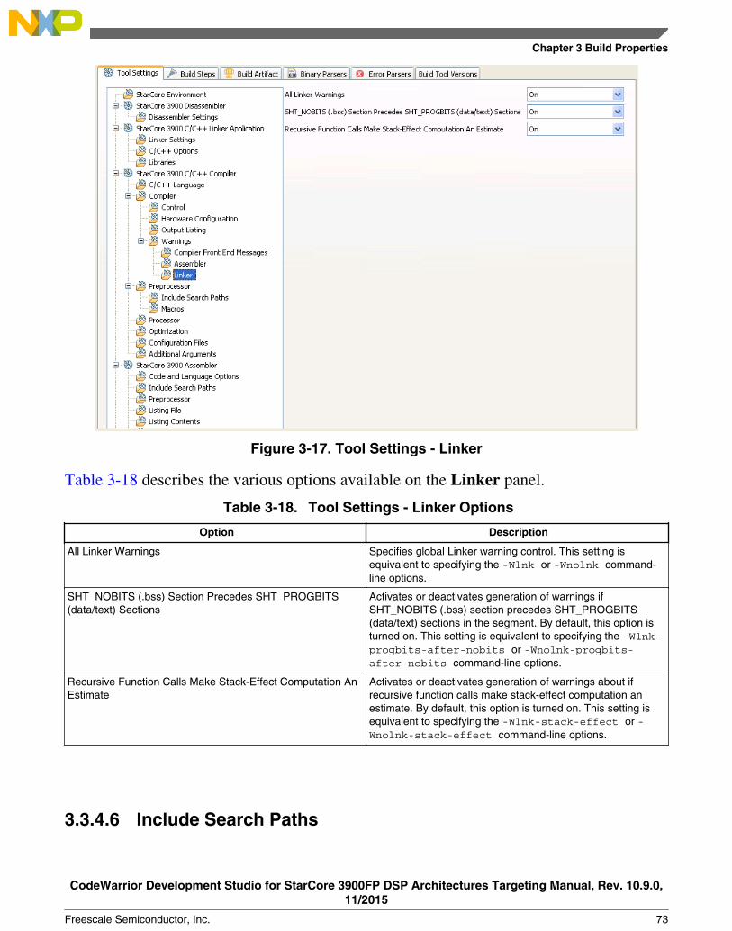
Figure 3-17. Tool Settings - Linker
Table 3-18 describes the various options available on the Linker panel.
Table 3-18. Tool Settings - Linker Options
Option Description
All Linker Warnings Specifies global Linker warning control. This setting isequivalent to specifying the -Wlnk or -Wnolnk command-line options.
SHT_NOBITS (.bss) Section Precedes SHT_PROGBITS(data/text) Sections
Activates or deactivates generation of warnings ifSHT_NOBITS (.bss) section precedes SHT_PROGBITS(data/text) sections in the segment. By default, this option isturned on. This setting is equivalent to specifying the -Wlnk-progbits-after-nobits or -Wnolnk-progbits-after-nobits command-line options.
Recursive Function Calls Make Stack-Effect Computation AnEstimate
Activates or deactivates generation of warnings about ifrecursive function calls make stack-effect computation anestimate. By default, this option is turned on. This setting isequivalent to specifying the -Wlnk-stack-effect or -Wnolnk-stack-effect command-line options.
3.3.4.6 Include Search Paths
Chapter 3 Build Properties
CodeWarrior Development Studio for StarCore 3900FP DSP Architectures Targeting Manual, Rev. 10.9.0,11/2015
Freescale Semiconductor, Inc. 73

Use this panel to specify paths to search for #include files. Note that the IDE displays anerror message if a header file is in a different directory from the referencing source file.Sometimes, the IDE also displays an error message if a header file is in the samedirectory as the referencing source file.
For example, if you see the message Could not open source file myfile.h, you must add thepath for myfile.h to this panel.
Figure 3-18. Tool Settings - Include Search Paths
Table 3-19 lists and describes the toolbar buttons that help work with the file searchpaths.
Table 3-19. Tool Settings - Include Search Paths Toolbar Buttons
Button Description
Add - Click to open the Add directory path dialog box(Figure 3-19) and specify the file search path.
Delete - Click to delete the selected file search path. Toconfirm deletion, click Yes in the Confirm Delete dialog box.
Edit - Click to open the Edit directory path dialog box (Figure3-20) and update the selected object file search path.
Move up - Click to move the selected file search path oneposition higher in the list.
Move down - Click to move the selected file search path oneposition lower in the list.
Build Properties for StarCore
CodeWarrior Development Studio for StarCore 3900FP DSP Architectures Targeting Manual, Rev. 10.9.0,11/2015
74 Freescale Semiconductor, Inc.

Figure 3-19 shows the Add directory path dialog box.
Figure 3-19. Add directory path Dialog Box
Figure 3-20 shows the Edit directory path dialog box.
Figure 3-20. Edit directory path Dialog Box
The buttons in the Add directory path and Edit directory path dialog boxes help workwith the object file search paths.
• OK- Click to confirm the action and exit the dialog box.• Cancel - Click to cancel the action and exit the dialog box.• Workspace- Click to display the Folder Selection dialog box and specify the object
file search path. The resulting path, relative to the workspace, appears in theappropriate list.
• File system- Click to display the Browse for Folder dialog box and specify theobject file search path. The resulting path appears in the appropriate list.
3.3.4.7 Macros
Use this panel to define and undefine preprocessor macros. You can specify multiplemacros and change the order in which the IDE uses the macros.
Chapter 3 Build Properties
CodeWarrior Development Studio for StarCore 3900FP DSP Architectures Targeting Manual, Rev. 10.9.0,11/2015
Freescale Semiconductor, Inc. 75

Figure 3-21. Tool Settings - Macros
Table 3-20 describes the various options available on the Macros panel.
Table 3-20. Tool Settings - Macros Options
Option Description
Define Preprocessor Macros Define preprocessor macros and optionally assign theirvalues. This setting is equivalent to specifying the -Dname[=value] command-line option. To assign a value, usethe equal sign (=) with no white space. For example, thissyntax defines a preprocessor value namedEXTENDED_FEATURE and assigns ON as its value:EXTENDED_FEATURE=ON
Note that if you do not assign a value to the macro, the shellassigns a default value of 1.
Undefine Preprocessor Macros Undefine preprocessor macros. This setting is equivalent tospecifying the -U name command-line option. For example,this syntax undefines the EXTENDED_ FEATURE macro:EXTENDED_FEATURE
Note that the shell processes these items after it processes allDefined Preprocessor Macros items.
Build Properties for StarCore
CodeWarrior Development Studio for StarCore 3900FP DSP Architectures Targeting Manual, Rev. 10.9.0,11/2015
76 Freescale Semiconductor, Inc.

Table 3-21 lists and describes the toolbar buttons that help work with the macros.
Table 3-21. Tool Settings - Macros Toolbar Buttons
Button Description
Add - Click to add a defined preprocessor macro.
Delete - Click to delete the selected macro. To confirmdeletion, click Yes in the Confirm Delete dialog box.
Edit - Click to update the selected defined preprocessormacro.
Move up - Click to move the selected macro one positionhigher in the list.
Move down - Click to move the selected macro one positionlower in the list.
3.3.4.8 Processor
Use this panel to enable fused multiply and accumulate operation.
Chapter 3 Build Properties
CodeWarrior Development Studio for StarCore 3900FP DSP Architectures Targeting Manual, Rev. 10.9.0,11/2015
Freescale Semiconductor, Inc. 77

Figure 3-22. Tool Settings - Processor Panel
Table 3-22 explains the options available on the Processor panel.
Table 3-22. Tool Settings - Processor
Option Description
Fused multiply and accumulate Check to enable the fused multiply and accumulate operation.Fused multiply and add are generated only if hardwarefloating point support is enabled on the SC3900fp compiler.
3.3.4.9 Optimization
Use this panel to control compiler optimizations. Compiler optimization can be applied ineither global or non-global optimization mode. You can apply global optimization at theend of the development cycle, after compiling and optimizing all source files individuallyor in groups.
Build Properties for StarCore
CodeWarrior Development Studio for StarCore 3900FP DSP Architectures Targeting Manual, Rev. 10.9.0,11/2015
78 Freescale Semiconductor, Inc.

Figure 3-23. Tool Settings - Optimization
Table 3-23 describes the various options available on the Optimization panel.
Table 3-23. Tool Settings - Optimization Options
Option Description
Alignment Specify the alignment level that the compiler uses. Thissetting is equivalent to specifying the -align level command-line option.
• default - level 0 applies to size optimizations, and level2 applies to speed optimizations
• 0 - disable alignment• 1 - align hardware loops• 2 - align hardware and software loops• 3 - align all existing labels• 4 - align all existing labels and subroutine-return points
Note that using a higher alignment constraint increasesexecution speed but also increases object-code size.
Optimization Level Specify the optimizations that you want the compiler to applyto the generated object code:
• 0 - Disable optimizations. This setting is equivalent tospecifying the -O0 command-line option. The compilergenerates unoptimized, linear assembly-language code.
• 1 - The compiler performs all target-independent (thatis, non-parallelized) optimizations, such as functioninlining. This setting is equivalent to specifying the -O1command-line option.
Table continues on the next page...
Chapter 3 Build Properties
CodeWarrior Development Studio for StarCore 3900FP DSP Architectures Targeting Manual, Rev. 10.9.0,11/2015
Freescale Semiconductor, Inc. 79
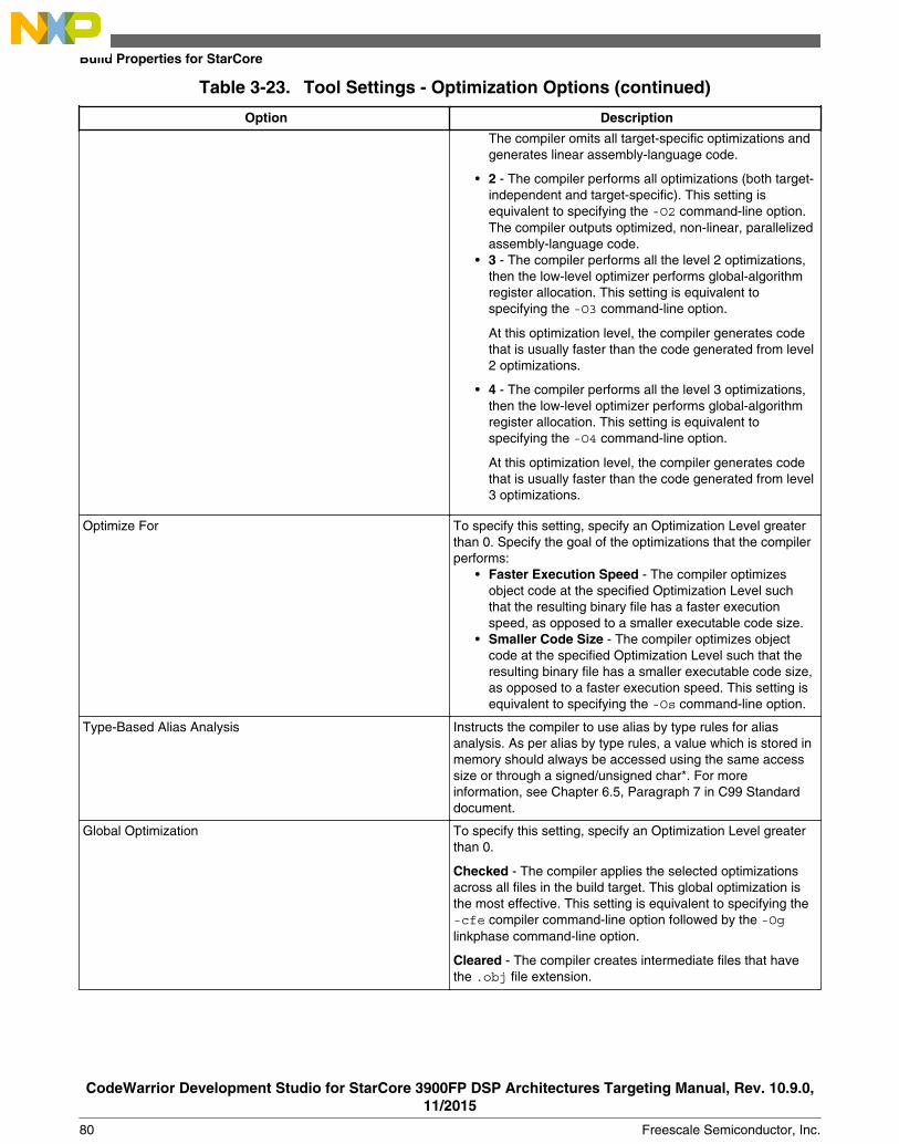
Table 3-23. Tool Settings - Optimization Options (continued)
Option Description
The compiler omits all target-specific optimizations andgenerates linear assembly-language code.
• 2 - The compiler performs all optimizations (both target-independent and target-specific). This setting isequivalent to specifying the -O2 command-line option.The compiler outputs optimized, non-linear, parallelizedassembly-language code.
• 3 - The compiler performs all the level 2 optimizations,then the low-level optimizer performs global-algorithmregister allocation. This setting is equivalent tospecifying the -O3 command-line option.
At this optimization level, the compiler generates codethat is usually faster than the code generated from level2 optimizations.
• 4 - The compiler performs all the level 3 optimizations,then the low-level optimizer performs global-algorithmregister allocation. This setting is equivalent tospecifying the -O4 command-line option.
At this optimization level, the compiler generates codethat is usually faster than the code generated from level3 optimizations.
Optimize For To specify this setting, specify an Optimization Level greaterthan 0. Specify the goal of the optimizations that the compilerperforms:
• Faster Execution Speed - The compiler optimizesobject code at the specified Optimization Level suchthat the resulting binary file has a faster executionspeed, as opposed to a smaller executable code size.
• Smaller Code Size - The compiler optimizes objectcode at the specified Optimization Level such that theresulting binary file has a smaller executable code size,as opposed to a faster execution speed. This setting isequivalent to specifying the -Os command-line option.
Type-Based Alias Analysis Instructs the compiler to use alias by type rules for aliasanalysis. As per alias by type rules, a value which is stored inmemory should always be accessed using the same accesssize or through a signed/unsigned char*. For moreinformation, see Chapter 6.5, Paragraph 7 in C99 Standarddocument.
Global Optimization To specify this setting, specify an Optimization Level greaterthan 0.
Checked - The compiler applies the selected optimizationsacross all files in the build target. This global optimization isthe most effective. This setting is equivalent to specifying the-cfe compiler command-line option followed by the -Oglinkphase command-line option.
Cleared - The compiler creates intermediate files that havethe .obj file extension.
Build Properties for StarCore
CodeWarrior Development Studio for StarCore 3900FP DSP Architectures Targeting Manual, Rev. 10.9.0,11/2015
80 Freescale Semiconductor, Inc.

3.3.4.10 Configuration Files
Use this panel to specify the application-configuration file view, and the customapplication-configuration file.
Figure 3-24. Tool Settings - Configuration Files
Table 3-24 describes the various options available on the Configuration Files panel.
Table 3-24. Tool Settings - Configuration Files Options
Option Description
Configuration View Enter the application-configuration file view that the buildtarget uses. This setting is equivalent to specifying the -viewidentifier command-line option. If you use this text box,you must specify a path in the Application Configuration Filetext box.
Application Configuration File Enter the path to a custom application-configuration file. Thissetting is equivalent to specifying the -ma filenamecommand line option. Alternatively, click the Browse button,then use the resulting dialog box to specify the file. Clear thistext box to use a default application-configuration file. Use acustom application-configuration file to apply different settings
Chapter 3 Build Properties
CodeWarrior Development Studio for StarCore 3900FP DSP Architectures Targeting Manual, Rev. 10.9.0,11/2015
Freescale Semiconductor, Inc. 81

Table 3-24. Tool Settings - Configuration Files Options
Option Description
and optimization levels to various files and functions of thebuild target. An application-configuration file must havethe .appli filename extension.
3.3.4.11 Additional Arguments
Use this panel to specify command-line options that the shell program (scc) passesdirectly to individual build tools (such as the front-end compiler, the various optimizers,and the assembler). Because the IDE shares this panel among multiple tools, just theoptions that apply to the selected tool appear in each instance of the panel.
NOTEThe IDE applies the command-line options that you specify inthis panel to the compilation of the C-language source files in abuild target (even the options that you enter in the ToAssembler text box). To pass command-line options to theassembler for application to the assembly-language files in abuild target, use the Read Options from File text box of theStarCore 3900 Assembler > Preprocessor panel.
Build Properties for StarCore
CodeWarrior Development Studio for StarCore 3900FP DSP Architectures Targeting Manual, Rev. 10.9.0,11/2015
82 Freescale Semiconductor, Inc.

Figure 3-25. Tool Settings - Additional Arguments
Table 3-25 describes the various options available on the Additional Arguments panel.
Table 3-25. Tool Settings - Additional Arguments Options
Option Description
To Front-End Enter command-line options for the shell program to pass tothe front-end compiler. This setting is equivalent to specifyingthe -Xcfe command-line option.
To Assembler Enter command-line options for the shell program to pass tothe assembler. This setting is equivalent to specifying the -Xasm command-line option.
To Shell Enter command-line options for the IDE to pass to the shellprogram. The IDE passes the options exactly as you typethem and does not check for errors.
3.3.5 StarCore 3900 Assembler
Use this panel to specify the command, options, and expert settings for the build toolassembler.
Chapter 3 Build Properties
CodeWarrior Development Studio for StarCore 3900FP DSP Architectures Targeting Manual, Rev. 10.9.0,11/2015
Freescale Semiconductor, Inc. 83
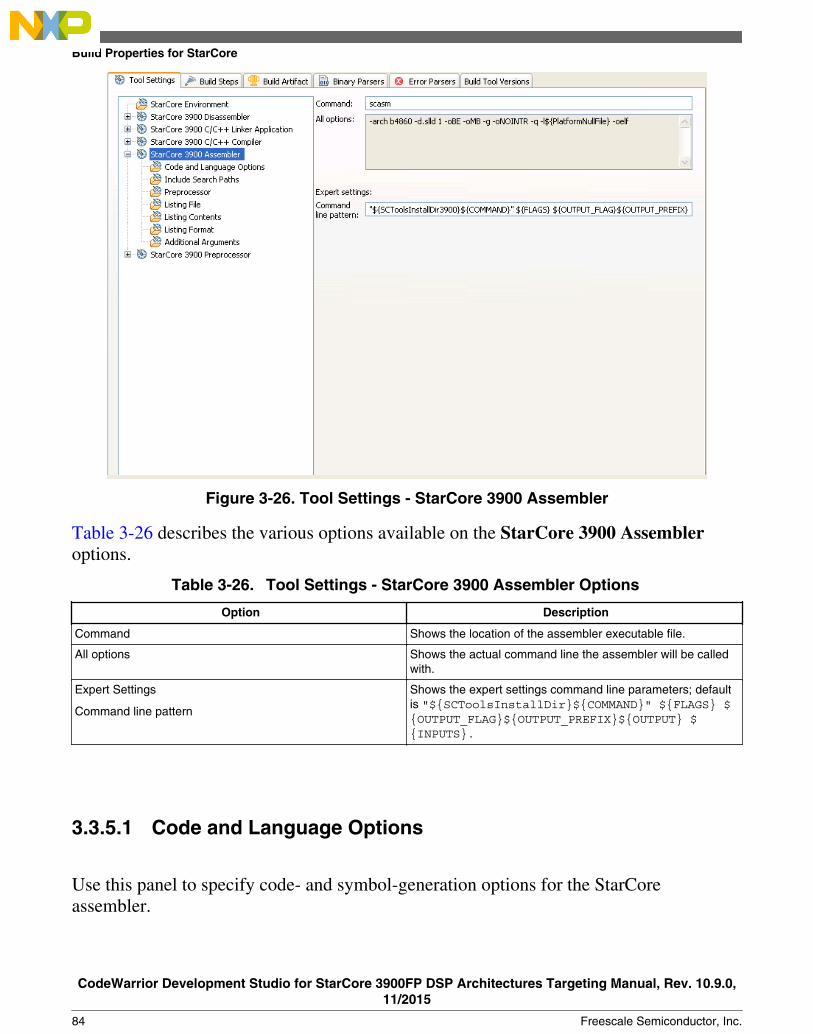
Figure 3-26. Tool Settings - StarCore 3900 Assembler
Table 3-26 describes the various options available on the StarCore 3900 Assembleroptions.
Table 3-26. Tool Settings - StarCore 3900 Assembler Options
Option Description
Command Shows the location of the assembler executable file.
All options Shows the actual command line the assembler will be calledwith.
Expert Settings
Command line pattern
Shows the expert settings command line parameters; defaultis "${SCToolsInstallDir}${COMMAND}" ${FLAGS} ${OUTPUT_FLAG}${OUTPUT_PREFIX}${OUTPUT} ${INPUTS}.
3.3.5.1 Code and Language Options
Use this panel to specify code- and symbol-generation options for the StarCoreassembler.
Build Properties for StarCore
CodeWarrior Development Studio for StarCore 3900FP DSP Architectures Targeting Manual, Rev. 10.9.0,11/2015
84 Freescale Semiconductor, Inc.

Figure 3-27. Tool Settings - Code and Language Options
Table 3-27 describes the various options available on the Code and Language Optionspanel.
Table 3-27. Tool Settings - Code and Language Options
Option Description
Generate Debugging Information Checked - The assembler produces symbolic information fordebugging the build target.
Cleared - The assembler does not produce symbolicinformation.
Ignore Case in Symbol Names Checked - The assembler ignores the case of symbol,section, and macro names. This setting corresponds to the ICoption of the OPT directive and to the -oic command-lineoption.
Cleared - The assembler considers the case of symbol,section, and macro names.
Write Symbols to Object File Checked - The assembler writes symbol information to theobject files that it generates. This setting corresponds to theSO option of the OPT directive and to the -oso command-line option.
Cleared - The assembler does not write symbol information toassembler-generated object files.
Table continues on the next page...
Chapter 3 Build Properties
CodeWarrior Development Studio for StarCore 3900FP DSP Architectures Targeting Manual, Rev. 10.9.0,11/2015
Freescale Semiconductor, Inc. 85

Table 3-27. Tool Settings - Code and Language Options (continued)
Option Description
Enable Check Summing Checked - The assembler allows check-summing ofinstruction and data values and clearing the cumulativechecksum.
Cleared - The assembler does not allow check summing ofinstruction and data values. You can use the @CHK() functionto obtain the checksum value.
Note that the assembler never preserves a comment line in amacro definition that starts with two consecutive semicolons(;;). This setting corresponds to the CK option of the OPTdirective and to the -ock command-line option.
Continue Check Summing Checked-The assembler re-enables check summing ofinstructions and data. This setting corresponds to the CONTCKoption of the OPT directive and to the -ocontck command-line option. Checking this checkbox does not cause theassembler to clear the cumulative checksum value. Cleared-The assembler does not re-enable check summing ofinstructions and data.
Do Not Restrict Directives in Loops Checked - The assembler suppresses error messagesrelated to directives that might be invalid in DO loops. Thissetting corresponds to the DLD option of the OPT directive andto the -odld command-line option.
Cleared - The assembler generates error messages relatedto directives that might be invalid in DO loops.
Pack Strings Checked - The assembler packs strings that appear in theDefine Constant ( DC) directive. This setting corresponds tothe PS option of the OPT directive and to the -ops command-line option. The assembler packs individual bytes of stringsinto consecutive target words for the length of the string.
Cleared - The assembler does not pack strings that appear inthe DC directive.
Scan MACLIB for Include Files Checked - The assembler searches for #include files in thepaths shown in the Macro Library (MACLIB) Search Paths list,as well as the paths shown in the Include Search Paths panelof the StarCore Assembler. This setting corresponds to the MIoption of the OPT directive and to the -omi command-lineoption.
Cleared - The assembler searches for include files just in thepaths shown in the Include Search Paths panel of theStarCore Assembler.
Enable Cycle Counts Checked - The assembler enables the cycle counter andclear-total-cycle-count features. This setting corresponds tothe CC option of the OPT directive and to the -occ command-line option. Checking this checkbox causes the listing file toshow a cycle count for each instruction entry.
Cleared - The assembler disables the cycle counter.
Note that cycle counts assume a full instruction-fetch pipelineand no wait states.
Table continues on the next page...
Build Properties for StarCore
CodeWarrior Development Studio for StarCore 3900FP DSP Architectures Targeting Manual, Rev. 10.9.0,11/2015
86 Freescale Semiconductor, Inc.

Table 3-27. Tool Settings - Code and Language Options (continued)
Option Description
Preserve Comment Lines in Macros Checked - The assembler preserves comment lines inmacros. This setting corresponds to the CM option of the OPTdirective and to the -ocm command-line option.
Cleared - The assembler does not preserve comment lines inmacros.
Make All Section Symbols Global Checked - The assembler treats all sections as if you haddeclared them explicitly as GLOBAL sections. This settingcorresponds to the GL option of the OPT directive and to the -ogl command-line option. You must check this checkboxbefore explicitly defining any section in a source file.
Cleared - The assembler does not treat all sections as if youhad declared them explicitly as GLOBAL sections.
Perform Interrupt Location Checks Checked-The assembler checks for DSP instructions thatcannot appear in the interrupt-vector locations of programmemory. This setting corresponds to the INTR option of theOPT directive and to the - ointr command-line option.Cleared-The assembler does not check for DSP instructionsthat cannot appear in the interrupt- vector locations ofprogram memory.
Expand Define Symbols in Strings Checked - The assembler expands DEFINE symbols instrings. This setting corresponds to the DEX option of the OPTdirective and to the -odex command-line option.
Cleared - The assembler does not expand DEFINE symbolsin strings.
Preserve Object File on Errors Checked - The assembler preserves object files if assemblyerrors occur. This setting corresponds to the SVO option ofthe OPT directive and to the - osvo command-line option.
Cleared - The assembler discards object files if assemblyerrors occur.
Dynamic Programming Rule Checks Specify how the assembler reports violations of programmingrules:
· Disable All - The assembler does not report violations ofdynamic StarCore 3900FP DSP programming rules. Thissetting is the default behavior when you invoke the assemblerfrom the command line.
· Default - The assembler chooses whether to reportviolations of dynamic StarCore 3900FP DSP programmingrules.
Enable All - The assembler reports violations of dynamicStarCore 3900FP DSP programming rules. The IDE passesthe -s all option to the assembler.
Macro Library (MACLIB) Search Paths Lists paths to search for #include files. The assemblersearches the paths in the order shown in this list. Use thesetoolbar buttons to work with the search paths:
• Add - Click, then use the resulting dialog box to specifythe path.
• Delete - Click to remove the selected path.• Edit - Click, then use the resulting dialog box to change
the selected path.
Chapter 3 Build Properties
CodeWarrior Development Studio for StarCore 3900FP DSP Architectures Targeting Manual, Rev. 10.9.0,11/2015
Freescale Semiconductor, Inc. 87
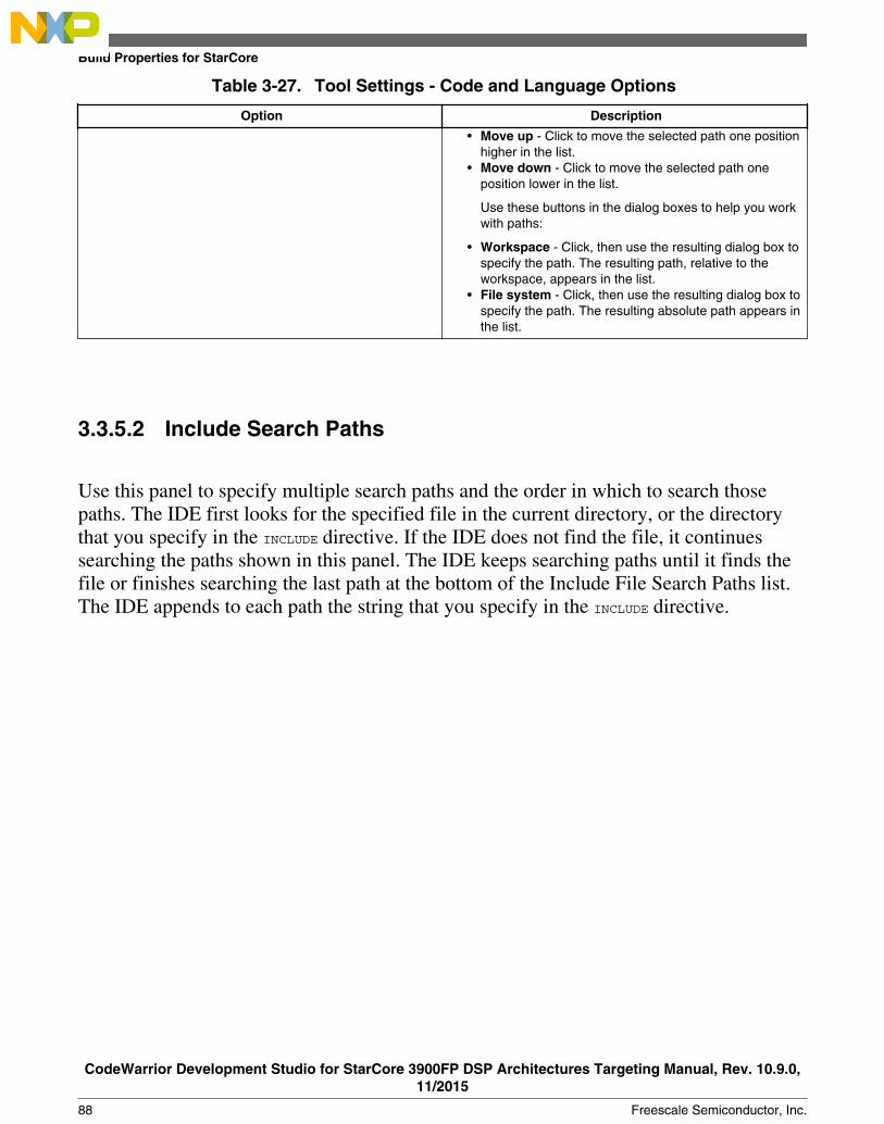
Table 3-27. Tool Settings - Code and Language Options
Option Description
• Move up - Click to move the selected path one positionhigher in the list.
• Move down - Click to move the selected path oneposition lower in the list.
Use these buttons in the dialog boxes to help you workwith paths:
• Workspace - Click, then use the resulting dialog box tospecify the path. The resulting path, relative to theworkspace, appears in the list.
• File system - Click, then use the resulting dialog box tospecify the path. The resulting absolute path appears inthe list.
3.3.5.2 Include Search Paths
Use this panel to specify multiple search paths and the order in which to search thosepaths. The IDE first looks for the specified file in the current directory, or the directorythat you specify in the INCLUDE directive. If the IDE does not find the file, it continuessearching the paths shown in this panel. The IDE keeps searching paths until it finds thefile or finishes searching the last path at the bottom of the Include File Search Paths list.The IDE appends to each path the string that you specify in the INCLUDE directive.
Build Properties for StarCore
CodeWarrior Development Studio for StarCore 3900FP DSP Architectures Targeting Manual, Rev. 10.9.0,11/2015
88 Freescale Semiconductor, Inc.

Figure 3-28. Tool Settings - Include Search Paths
Table 3-28 lists and describes the toolbar buttons that help work with the file searchpaths.
Table 3-28. Tool Settings - Include Search Paths Toolbar Buttons
Button Description
Add - Click to open the Add directory path dialog box( Include Search Paths) and specify the file search path.
Delete - Click to delete the selected file search path. Toconfirm deletion, click Yes in the Confirm Delete dialog box.
Edit - Click to open the Edit directory path dialog box( Include Search Paths) and update the selected object filesearch path.
Move up - Click to move the selected file search path oneposition higher in the list.
Move down - Click to move the selected file search path oneposition lower in the list.
Figure 3-29 shows the Add directory path dialog box.
Chapter 3 Build Properties
CodeWarrior Development Studio for StarCore 3900FP DSP Architectures Targeting Manual, Rev. 10.9.0,11/2015
Freescale Semiconductor, Inc. 89

Figure 3-29. Add directory path Dialog Box
Figure 3-30 shows the Edit directory path dialog box.
Figure 3-30. Edit directory path Dialog Box
The buttons in the Add directory path and Edit directory path dialog boxes help workwith the object file search paths.
• OK- Click to confirm the action and exit the dialog box.• Cancel- Click to cancel the action and exit the dialog box.• Workspace- Click to display the Folder Selection dialog box and specify the object
file search path. The resulting path, relative to the workspace, appears in theappropriate list.
• File system- Click to display the Browse for Folder dialog box and specify theobject file search path. The resulting path appears in the appropriate list.
3.3.5.3 Preprocessor
Use this panel to specify preprocessor behavior. You can specify whether to displaybanner information or verbose progress messages, and you can control error output. Also,you can specify substitution strings for the preprocessor.
Build Properties for StarCore
CodeWarrior Development Studio for StarCore 3900FP DSP Architectures Targeting Manual, Rev. 10.9.0,11/2015
90 Freescale Semiconductor, Inc.

Figure 3-31. Tool Settings - Preprocessor
Table 3-29 describes the various options available on the Preprocessor panel.
Table 3-29. Tool Settings - Preprocessor Options
Option Description
Display Banner Checked - The assembler shows banner information.
Cleared - The assembler hides banner information.
Note that this option has no effect on hosts where the defaultsetting is to hide the banner.
Show Verbose Assembly Progress Messages Checked - The assembler reports the progress of theassembly process to the standard error output stream. Forexample, the assembler reports the beginning of each passand the opening and closing of input files. You can use thisinformation to monitor the assembly process and ensure thatit proceeds normally.
Cleared - The assembler does not report assembly progressto the standard error-output stream.
Read Options from File Enter the path to a file that specifies command-line options forassembler use. Alternatively, click the Browse button, thenuse the resulting dialog box to specify the file.
Redirect Errors to File Enter the path to a file that the assembler uses in place of thedefault error file (errfil). The Overwrite Existing ErrorFile checkbox controls how the assembler writes to the filethat you specify in this text box.
Table continues on the next page...
Chapter 3 Build Properties
CodeWarrior Development Studio for StarCore 3900FP DSP Architectures Targeting Manual, Rev. 10.9.0,11/2015
Freescale Semiconductor, Inc. 91

Table 3-29. Tool Settings - Preprocessor Options (continued)
Option Description
Overwrite Existing Error File Checked - The assembler overwrites the file that you specifyin the Redirect Errors to File text box.
Cleared - The assembler appends information to the file thatyou specify in the Redirect Errors to File text box.
Defined Symbols Specify substitution strings that the assembler applies to allthe assembly-language modules in the build target. Enter justthe string portion of a substitution string. The IDE prependsthe -d token to each string that you enter. For example,entering opt1 x produces this result on the command line: -dopt1 x Note that this option is similar to the DEFINEdirective, but applies to all assembly-language modules in abuild target. Use these toolbar buttons to work with thesubstitution strings:
• Add - Click, then use the resulting dialog box to specifythe string.
• Delete - Click to remove the selected string.• Edit - Click, then use the resulting dialog box to change
the selected string.• Move up - Click to move the selected string one
position higher in the list.• Move down - Click to move the selected string one
position lower in the list.
3.3.5.4 Listing File
Use this panel to specify whether the assembler generates a listing file. When generatinga listing file, you can specify whether the assembler also prints a memory-utilizationreport. Also, you can specify the types of warnings that the assembler includes in thelisting file. ( Figure 3-32)
NOTEUse the Additional Arguments panel of the StarCore Assemblerto specify options that you want to apply to all assembly-language files in the current build target. Use the OPT directivefor options that you want to apply to just the assembly-languagesource file in which the OPT directive appears.
Build Properties for StarCore
CodeWarrior Development Studio for StarCore 3900FP DSP Architectures Targeting Manual, Rev. 10.9.0,11/2015
92 Freescale Semiconductor, Inc.

Figure 3-32. Tool Settings - Listing File
Table 3-30 describes the various options available on the Listing File panel.
Table 3-30. Tool Settings - Listing File Options
Option Description
Generate Listing File Checked - The assembler creates a listing file namedlstfil.lst.
Cleared - The assembler does not create a list file.
Listing File Debug To specify this setting, check the Generate Listing Filecheckbox.
Checked - The assembler uses the source listing, instead ofthe assembly-language source file, as the debug source file.This setting corresponds to the LDB option of the OPTdirective and to the -oldb command-line option.
Cleared - The assembler uses the assembly language sourcefile, instead of the source listing, as the debug source file.
Print Memory Utilization Report To specify this setting, check the Generate Listing Filecheckbox.
Checked - The assembler writes a report of load and runtimememory-use information to the listing file. This settingcorresponds to the MU option of the OPT directive and to the -omu command-line option.
Cleared - The assembler does not write the memory-utilization report to the listing file.
Table continues on the next page...
Chapter 3 Build Properties
CodeWarrior Development Studio for StarCore 3900FP DSP Architectures Targeting Manual, Rev. 10.9.0,11/2015
Freescale Semiconductor, Inc. 93

Table 3-30. Tool Settings - Listing File Options (continued)
Option Description
Print Warning for Unresolved References To specify this setting, check the Generate Listing Filecheckbox.
Checked - The assembler generates a warning at assemblytime for each unresolved external reference. This setting,valid just in relocatable mode, corresponds to the UR option ofthe OPT directive and to the -our command-line option.
Cleared - The assembler does not generate a warning atassembly time for each unresolved external reference.
Print All Warnings To specify this setting, check the Generate Listing Filecheckbox.
Checked - The assembler writes all warning messages to thelisting file. This setting corresponds to the W option of the OPTdirective and to the -ow command-line option.
Cleared - The assembler does not write all warningmessages to the listing file.
3.3.5.5 Listing Contents
Use this panel to specify the information that the assembler generates in a listing file.
Build Properties for StarCore
CodeWarrior Development Studio for StarCore 3900FP DSP Architectures Targeting Manual, Rev. 10.9.0,11/2015
94 Freescale Semiconductor, Inc.

Figure 3-33. Tool Settings - Listing Contents
Table 3-31 describes the various options available on the Listing Contents panel.
Table 3-31. Tool Settings - Listing Contents Options
Option Description
Generate Listing Headers Checked - The assembler writes listing headers, titles, andsubtitles to the listing file. This setting corresponds to the HDRoption of the OPT directive and to the -ohdr command-lineoption.
Cleared - The assembler does not write listing headers, titles,and subtitles to the listing file.
Print DC Expansion Checked - The assembler writes Define Constant (DC)expansions to the listing file. This setting corresponds to theCEX option of the OPT directive and to the -ocex command-line option.
Cleared - The assembler does not write Define Constantexpansions to the listing file.
Expand DEFINE Directive Strings Checked - The assembler writes expanded DEFINEdirectives to the listing file. This setting corresponds to the MDoption of the OPT directive and to the - omd command-lineoption.
Cleared - The assembler does not write expanded DEFINEdirectives to the listing file.
Table continues on the next page...
Chapter 3 Build Properties
CodeWarrior Development Studio for StarCore 3900FP DSP Architectures Targeting Manual, Rev. 10.9.0,11/2015
Freescale Semiconductor, Inc. 95

Table 3-31. Tool Settings - Listing Contents Options (continued)
Option Description
Print Conditional Assembly Directive Checked - The assembler writes conditional-assemblydirectives to the listing file. This setting corresponds to the CLoption of the OPT directive and to the -ocl command-lineoption. Cleared - The assembler does not write conditional-assembly directives to the listing file.
Print Conditional Assembly Checked - The assembler writes conditional-assembly andsection nesting-level information to the listing file. This settingcorresponds to the NL option of the OPT directive and to the -onl command-line option.
Cleared - The assembler does not write conditional-assemblyand section nesting-level information to the listing file.
Print Skipped Conditional Assembly Lines Checked - The assembler writes to the listing file assembly-language statements skipped due to conditional assembly.This setting corresponds to the U option of the OPT directiveand to the -ou command-line option.
Cleared - The assembler does not write to the listing fileassembly-language statements skipped due to conditionalassembly.
Print Macro Definitions Checked - The assembler writes macro definitions to thelisting file. This setting corresponds to the MD option of theOPT directive and to the -omd command-line option.
Cleared - The assembler does not write macro definitions tothe listing file.
Print Macro Calls Checked - The assembler writes macro calls to the listing file.This setting corresponds to the MC option of the OPT directiveand to the -omc command-line option.
Cleared - The assembler does not write macro calls to thelisting file.
Print Macro Expansions Checked - The assembler writes macro expansions to thelisting file. This setting corresponds to the MEX option of theOPT directive and to the -omex command-line option.
Cleared - The assembler does not write macro expansions tothe listing file.
3.3.5.6 Listing Format
Use this panel to specify format of the information that the assembler generates in alisting file.
Build Properties for StarCore
CodeWarrior Development Studio for StarCore 3900FP DSP Architectures Targeting Manual, Rev. 10.9.0,11/2015
96 Freescale Semiconductor, Inc.
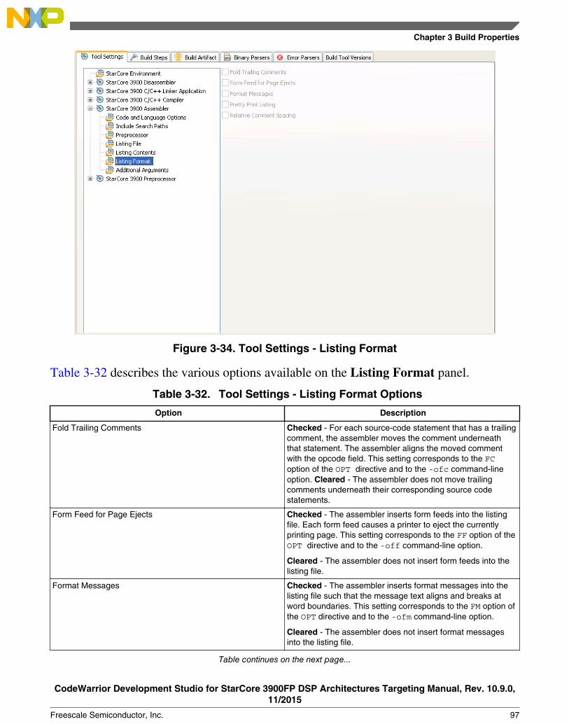
Figure 3-34. Tool Settings - Listing Format
Table 3-32 describes the various options available on the Listing Format panel.
Table 3-32. Tool Settings - Listing Format Options
Option Description
Fold Trailing Comments Checked - For each source-code statement that has a trailingcomment, the assembler moves the comment underneaththat statement. The assembler aligns the moved commentwith the opcode field. This setting corresponds to the FCoption of the OPT directive and to the -ofc command-lineoption. Cleared - The assembler does not move trailingcomments underneath their corresponding source codestatements.
Form Feed for Page Ejects Checked - The assembler inserts form feeds into the listingfile. Each form feed causes a printer to eject the currentlyprinting page. This setting corresponds to the FF option of theOPT directive and to the -off command-line option.
Cleared - The assembler does not insert form feeds into thelisting file.
Format Messages Checked - The assembler inserts format messages into thelisting file such that the message text aligns and breaks atword boundaries. This setting corresponds to the FM option ofthe OPT directive and to the -ofm command-line option.
Cleared - The assembler does not insert format messagesinto the listing file.
Table continues on the next page...
Chapter 3 Build Properties
CodeWarrior Development Studio for StarCore 3900FP DSP Architectures Targeting Manual, Rev. 10.9.0,11/2015
Freescale Semiconductor, Inc. 97

Table 3-32. Tool Settings - Listing Format Options (continued)
Option Description
Pretty Print Listing Checked - The assembler aligns listing-file fields at fixedcolumn positions (without regard to the related source file'sformat). This setting corresponds to the PP option of the OPTdirective and to the -opp command-line option.
Cleared - The assembler does not align listing-file fields atfixed column positions.
Relative Comment Spacing Checked - The assembler uses relative comment spacing inthe listing file. Checking this checkbox causes the position ofcomments in the listing file to float. This setting correspondsto the RC option of the OPT directive and to the -orccommand-line option. Cleared - The assembler uses fixedcomment spacing in the listing file.
3.3.5.7 Additional Arguments
Use this panel to specify StarCore assembler additional arguments.
Figure 3-35. Tool Settings - Additional Arguments
Build Properties for StarCore
CodeWarrior Development Studio for StarCore 3900FP DSP Architectures Targeting Manual, Rev. 10.9.0,11/2015
98 Freescale Semiconductor, Inc.

Table 3-33 describes the various options available on the Additional Arguments panel.
Table 3-33. Tool Settings - Additional Arguments Options
Option Description
StarCore 3900 Assembler Specify additional command-line options to the assembler.The arguments specified in this panel apply will to allassembly language files in the current build target.
3.3.6 StarCore 3900 Preprocessor
Use this panel to specify the command, options, and expert settings for the StarCore 3900preprocessor.
Figure 3-36. Tool Settings - StarCore 3900 Preprocessor
Chapter 3 Build Properties
CodeWarrior Development Studio for StarCore 3900FP DSP Architectures Targeting Manual, Rev. 10.9.0,11/2015
Freescale Semiconductor, Inc. 99

Table 3-34 describes the various options available on the StarCore 3900 Preprocessorpanel.
Table 3-34. Tool Settings - StarCore 3900 Preprocessor Options
Option Description
Command Shows the location of the disassembler executable file.
All options Shows the actual command line the disassembler will becalled with.
Expert Settings:
Command line pattern
Shows the expert settings command line parameters; defaultis "${SCToolsInstallDir}${COMMAND}" ${FLAGS} ${INPUTS}.
3.3.6.1 Preprocessor Settings
Use this panel to specify the Preprocessor behavior.
Figure 3-37. Tool Settings - Preprocessor Settings
Build Properties for StarCore
CodeWarrior Development Studio for StarCore 3900FP DSP Architectures Targeting Manual, Rev. 10.9.0,11/2015
100 Freescale Semiconductor, Inc.

Table 3-35 describes the various options available on the Preprocessor Settings panel.
Table 3-35. Tool Settings - Preprocessor Settings Options
Option Description
Keep All Comments Checked -The preprocessor preserves all the comments.
Cleared -The preprocessor does not preserve comments.
Chapter 3 Build Properties
CodeWarrior Development Studio for StarCore 3900FP DSP Architectures Targeting Manual, Rev. 10.9.0,11/2015
Freescale Semiconductor, Inc. 101

Build Properties for StarCore
CodeWarrior Development Studio for StarCore 3900FP DSP Architectures Targeting Manual, Rev. 10.9.0,11/2015
102 Freescale Semiconductor, Inc.

Chapter 4Debug Configurations
A CodeWarrior project can have multiple associated debug configurations.
A debug configuration is a named collection of settings that the CodeWarrior tools use.
The CodeWarrior project wizard generates launch configurations with names that followthe pattern projectname - configtype - targettype, where:
• projectname represents the name of the project• configtype represents the type of launch configuration• targettype represents the type of target software or hardware on which the launch
configuration acts
If you use the CodeWarrior wizard to create a new project, the IDE creates two debuggerrelated launch configurations:
• a Debug configuration that produces unoptimized code for development purposes• a Release configuration that produces code intended for production purposes
This chapter explains:
• Using Debug Configurations Dialog Box• Customizing Debug Configurations• Reverting Debug Configuration Settings
4.1 Using Debug Configurations Dialog Box
The Debug Configurations dialog box allows you to specify debugger-related settingsfor your CodeWarrior project.
CodeWarrior Development Studio for StarCore 3900FP DSP Architectures Targeting Manual, Rev. 10.9.0,11/2015
Freescale Semiconductor, Inc. 103

NOTEAs you modify a launch configuration's debugger settings, youcreate pending, or unsaved, changes to that launchconfiguration. To save the pending changes, you must click theApply button of the Debug Configurations dialog box, orclick the Close button and then the Yes button.
Table 4-1. Debug Configurations Dialog Box Tabs
Main
Arguments
Debugger Debug
Download
Other Executables
Symbolics
OS Awareness
Source
Environment
Common
Trace and Profile
4.1.1 Main
Use this tab to specify the project and the application you want to run or debug.
You can also specify a connection configuration on this tab.
The following figure shows the Main tab.
Using Debug Configurations Dialog Box
CodeWarrior Development Studio for StarCore 3900FP DSP Architectures Targeting Manual, Rev. 10.9.0,11/2015
104 Freescale Semiconductor, Inc.

Figure 4-1. Debug Configurations - Main Tab
The table below lists the various sections available on the Main tab page.
Table 4-2. Main tab sections
Section
Debug Session Type
C/C++ application
Build (if required) before launching
Target settings
4.1.1.1 Debug Session Type
You can use this section to select one of the pre-defined debug session type or create acustom debug session.
Chapter 4 Debug Configurations
CodeWarrior Development Studio for StarCore 3900FP DSP Architectures Targeting Manual, Rev. 10.9.0,11/2015
Freescale Semiconductor, Inc. 105

The table listed below describes the options in the Debug session type section in theMain tab page.
Table 4-3. Main Tab - Debug session type options and use cases
Option Typical Use Example
Attach Debug a target system without modifying its state at allinitially, but allow use of symbolics during actual debug.Useful for debugging a system that is already up and running.For more details, see Attach .
Connect Raw debug of a board without any software or symbolics.Useful during hardware bring up, and often combined withscripts for checking various aspects of the hardware. Formore details, see Connect .
Download Develop code that gets downloaded to the system ondebugger launch. Useful for bareboard code developmentwithout a working bootloader. For more details, seeDownload .
Custom Debug a target system using additional debugging features.Useful when a Custom debug configuration may needs to betransformed into an Attach or Connect configuration. Formore details, see Custom .
NOTEThe default debugger configuration causes the debugger tocache symbolics between sessions. However, the Connectcommand invalidates this cache. If you must preserve thecontents of the symbolics cache, and you plan to use theConnect command, clear the Cache Symbolics BetweenSessions checkbox in the Symbolics page of the DebugConfigurations dialog box just before you issue the Connectcommand.
The table listed below shows the debugging phases supported by the launchconfigurations at the run-time.
NOTEThe CodeWarrior Attach launch configuration does notsupport restarting a debugging session.
Table 4-4. CodeWarrior Launch Configurations-Run-time behavior
Startup Phase Download Attach Connect Custom
Load symbolic info formain application
Yes Yes Not applicable Optional
Reset target Yes No Yes Optional
Initialization Yes Optional Yes Optional
Table continues on the next page...
Using Debug Configurations Dialog Box
CodeWarrior Development Studio for StarCore 3900FP DSP Architectures Targeting Manual, Rev. 10.9.0,11/2015
106 Freescale Semiconductor, Inc.

Table 4-4. CodeWarrior Launch Configurations-Run-time behavior (continued)
Startup Phase Download Attach Connect Custom
Download Optional No Not applicable Optional
OS Awareness Optional Optional Not applicable Optional
Initialize PC Optional No Not applicable Optional
Stop at startup Optional No Not applicable Optional
4.1.1.1.1 Attach
The Attach command assumes that code is already running on the board and thereforedoes not run a target initialization file.
The state of the running program is undisturbed. The debugger loads symbolic debugginginformation for the current build target's executable. The result is that you have the samesource-level debugging facilities you have in a normal debug session (the ability to viewsource code and variables, and so on). The function does not reset the target, even if thelaunch configuration specifies this action. Further, the command loads symbolics, doesnot stop the target, run an initialization script, download an ELF file, or modify theprogram counter (PC).
NOTEThe debugger assumes that the current build target's generatedexecutable matches the code currently running on the target.
In a debugging session, the CodeWarrior Attach launch configuration skips setting upthe target hardware, and downloading the program image to that target hardware. Thecode image might reside on the target hardware already, or you might want to skip settingup the target hardware. Like the CodeWarrior Connect launch configuration, thesettings in the Arguments and Environment panels do not apply.
Although similar to a debugging session, the goal of attaching the debugger to a processis to get insight into the current state of that process, and to do so with minimaldisturbance to its state of execution. Having the debugger attach to a process skips mostof the state-altering steps involved in starting a debugging session, such as resetting thetarget, initializing the target, and downloading code. When the debugger finishesattaching to the process, you have many of the debugging capabilities that you wouldhave in a debugging session (such as source-level debugging, line breakpoints,watchpoints, console input/output, and so on).
Chapter 4 Debug Configurations
CodeWarrior Development Studio for StarCore 3900FP DSP Architectures Targeting Manual, Rev. 10.9.0,11/2015
Freescale Semiconductor, Inc. 107

NOTEThe debugger does not support restarting debugging sessionsthat you start by attaching the debugger to a process.
A process is an active program and related resources:
• Executing program code• An address space• One or more threads of execution. A thread is a unit of activity that has a program
counter and a set of processor registers• A data section• A set of resources, such as open files and pending signals
On a bareboard (without an operating system), a given core has one process: one threadof execution executing one program in one address space. With an operating system,there can be several processes on a given core (with one active at any givenmoment).These processes either run different programs in different address spaces oreven execute the same program, sharing an address space, open files, and so on.
4.1.1.1.2 Connect
The Connect command runs the target initialization file specified in the Properties for<Target> dialog box.
This file is responsible for setting up the board before connecting to it. The Connectfunction does not load any symbolic debugging information for the current build target'sexecutable. You therefore do not have access to source-level debugging and variabledisplay. The Connect command resets the target if the launch configuration specifies thisaction. Further, the command stops the target, (optionally) runs an initialization script,does not load symbolics, download an ELF file, or modify the program counter (PC).
In a debugging session, the CodeWarrior Connect launch configuration skipsdownloading the code image to the target hardware, and loading symbolics into thedebugger. Skipping these steps is useful for board initialization and bring-up. The codemight reside on the target hardware already, or you might want to skip loading symbolicsinto the debugger.
Like the CodeWarrior Attach launch configuration, the settings in the Arguments andEnvironment panels do not apply. The Source tab is available, however, so that you canspecify source paths in order to load an image after connecting the debugger to the target.
4.1.1.1.3 Download
Using Debug Configurations Dialog Box
CodeWarrior Development Studio for StarCore 3900FP DSP Architectures Targeting Manual, Rev. 10.9.0,11/2015
108 Freescale Semiconductor, Inc.

The Debug command resets the target if the launch configuration specifies the action.
Further, the command stops the target, (optionally) runs an initialization script,downloads the specified ELF file, and modifies the PC.
In a debugging session, the CodeWarrior Download launch configuration downloadsthe code image to the target hardware, and loads symbolics into the debugger. TheSource tab can be used to specify source paths in order to load an image after connectingthe debugger to the target.
4.1.1.1.4 Custom
Custom debug session type provides maximum flexibility to choose between debuggingfeatures.
4.1.1.2 C/C++ application
Use this section to control how C/C++ application is configured for the launchconfiguration.
The following table lists the options in the C/C++ application section in the Main tabpage.
Table 4-5. Main Tab - C/C++ application options
Option Description
Project Specifies the project to associate with the selected debuglaunch configuration. Click Browse to select a differentproject.
Application
NOTE: This option is disabled when the Connect debugsession type is selected.
Check, if you want to use an target application. And, specifythe name and location of the C or C++ application in thecorresponding text box.
Clear, if you do not want to use a target application.
Search Project - Click to open the Program Selection dialogbox and select from the binary files generated for the selectedproject.
Browse - Click to open the Open dialog box and select anybinary file.
Variables - Click to open the Select build variable dialogbox and select the build variables to be associated with theprogram.
Chapter 4 Debug Configurations
CodeWarrior Development Studio for StarCore 3900FP DSP Architectures Targeting Manual, Rev. 10.9.0,11/2015
Freescale Semiconductor, Inc. 109

Table 4-5. Main Tab - C/C++ application options
Option Description
NOTE: The dialog box displays an aggregation of multiplevariable databases and not all these variables aresuitable to be used from a build environment. Givenbelow are the variables that should be used:
• ProjDirPath - returns the absolute path ofthe current project location in the file system
${ProjDirPath}/Source/main.c"
• workspace_loc - returns the absolute path ofa workspace resource in the file system, or thelocation of the workspace if no argument isspecified
${workspace_loc:/ProjectName/Source main.c"
4.1.1.3 Build (if required) before launching
Use this section to control how auto build is configured for the launch configuration.
Changing this setting overrides the global workspace setting and can provide some speedimprovements.
The following table lists the options in the Build (if required) before launching sectionin the Main tab page.
Table 4-6. Main Tab - Build (if required) before launching options
Option Description
Build Configuration Specifies the configuration to build before launching theresulting executable.
Select configuration using `C/C++ Application' Select to build the build configuration that generated the filespecified in the Application text box, before launching theapplication.
When the Select configuration using `C/C++ Application'checkbox is selected, the Build Configuration drop-down listis disabled, and the build configuration that generated the filespecified in the Application text box is selected to be builtbefore launching the application.
Disable auto build Disables auto build for the launch configuration which mayimprove launch performance.
Enable auto build Enables auto build for the launch configuration which canslow down launch performance.
Use workspace settings (default) Uses the global auto build settings.
Configure Workspace Settings Opens the Launching preference panel where you canchange the workspace settings.
Using Debug Configurations Dialog Box
CodeWarrior Development Studio for StarCore 3900FP DSP Architectures Targeting Manual, Rev. 10.9.0,11/2015
110 Freescale Semiconductor, Inc.

4.1.1.4 Target settings
Use this section to control how the target is configured for the launch configuration.
The following table lists the options in the Target settings section in the Main tab page.
Table 4-7. Main Tab - Target settings Options
Option Description
Connection Specifies the applicable connection configuration.
Edit Click to edit the selected connection configuration.
New Click to create a new connection configuration for theselected project and application.
Execute reset sequence Check to apply reset settings, specified in the targetconfiguration. Alternatively, clear the option to ignore resetsettings.
NOTE: This option is disabled when the Connect or Attachdebug session type is selected.
Execute initialization script(s) Check to execute the initialization script(s), specified in thetarget configuration. Alternatively, clear the option to ignorethe initialization script(s).
NOTE: This option is disabled when the Connect debugsession type is selected.
Target Select the core to be debugged. The list of cores is displayedin the Target list, if the selected connection configuration is fora multicore target.
4.1.2 Arguments
Use this tab to specify the program arguments that an application uses and the workingdirectory for a run or debug configuration.
Chapter 4 Debug Configurations
CodeWarrior Development Studio for StarCore 3900FP DSP Architectures Targeting Manual, Rev. 10.9.0,11/2015
Freescale Semiconductor, Inc. 111

Figure 4-2. Debug Configurations-Arguments tab
The table below lists the various options available on the Arguments tab page.
Table 4-8. Arguments Tab options
Option Description
Program arguments Specifies the arguments passed on the command line.
Variables Click to select variables by name to include in the program arguments list.
Working Directory Specifies the run/debug configuration working directory.
Use default Check to specify the local directory or clear to specify a different workspace, a filesystem location, or variable.
Workspace Click to specify the path of, or browse to, a workspace relative working directory.
File System Click to specify the path of, or browse to, a file system directory.
Variables Click to specify variables by name to include in the working directory.
4.1.3 Debugger
Using Debug Configurations Dialog Box
CodeWarrior Development Studio for StarCore 3900FP DSP Architectures Targeting Manual, Rev. 10.9.0,11/2015
112 Freescale Semiconductor, Inc.
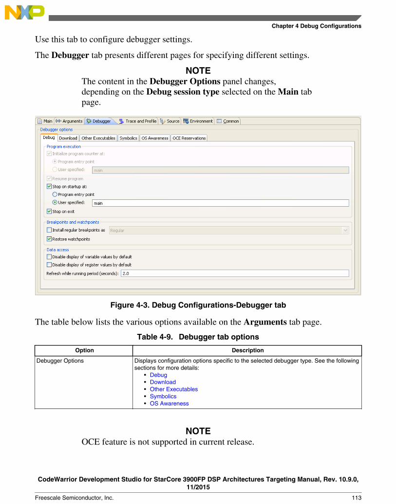
Use this tab to configure debugger settings.
The Debugger tab presents different pages for specifying different settings.
NOTEThe content in the Debugger Options panel changes,depending on the Debug session type selected on the Main tabpage.
Figure 4-3. Debug Configurations-Debugger tab
The table below lists the various options available on the Arguments tab page.
Table 4-9. Debugger tab options
Option Description
Debugger Options Displays configuration options specific to the selected debugger type. See the followingsections for more details:
• Debug• Download• Other Executables• Symbolics• OS Awareness
NOTEOCE feature is not supported in current release.
Chapter 4 Debug Configurations
CodeWarrior Development Studio for StarCore 3900FP DSP Architectures Targeting Manual, Rev. 10.9.0,11/2015
Freescale Semiconductor, Inc. 113

4.1.3.1 Debug
Use this page to specify the program execution options, Breakpoint and watchpointoptions, and target access behavior.
Figure 4-4. Debugger Options-Debug Page
NOTEThe options displayed on the Debug tab varies depending onthe selected launch configuration.
The table below lists the various options available on the Debug page.
Table 4-10. Debugger Options - Debug
Option Description
Initialize program counter at Controls the initialization of program counter.• Program entry point - Select to initialize the program counter at a
specified program entry pont.• User specified - Select to initialize the program counter at a user-
specified function. The default location is main.
NOTE: Disabling this option will also disable the Resume program andStop on startup at options.
Resume program Select to resume the execution after the program counter is initialized.
Table continues on the next page...
Using Debug Configurations Dialog Box
CodeWarrior Development Studio for StarCore 3900FP DSP Architectures Targeting Manual, Rev. 10.9.0,11/2015
114 Freescale Semiconductor, Inc.

Table 4-10. Debugger Options - Debug (continued)
Option Description
NOTE: Disabling this option will also disable the Stop on startup atoption.
Stop on startup at Stops program at specified location. When cleared, the program runs untilyou interrupt it manually, or until it hits a breakpoint.
• Program entry point - Select to stop the debugger at a specifiedprogram entry point.
• User specified - Select to stop the debugger at a user-specifiedfunction. The default location is main.
Stop on exit Check this option to have the debugger set a breakpoint at the code's exitpoint. For multicore projects, when you set this option for one project onone core, it is set for projects on the other cores. Clear this option toprevent the debugger from setting a breakpoint at the code's exit point.
Install regular breakpoints as Check this option to install breakpoints as either:• Regular• Hardware• Software
Clear this option to install breakpoints as Regular breakpoints.
Restore watchpoints Check this option to restore previous watchpoints.
Disable display of variable values by default Check this option to disable the display of variable values. Clear thisoption to enable the display of variable values
Disable display of register values by default Check this option to disable the display of register values. Clear this optionto enable the display of register values
Refresh while running period (seconds) Specifies the refresh period used when a view is configured to refresh,while the application is running. By default, the refresh period is set to twoseconds.
4.1.3.2 Download
Use this page to specify which executable code sections the debugger downloads to thetarget, and whether the debugger should read back those sections and verify them.
NOTESelecting all options in the Program Download Options groupsignificantly increases download time.
Initial Launch options apply to the first debugging session. Successive Runs optionsapply to subsequent debugging sessions.
The Download options control whether the debugger downloads the specified ProgramSection Data type to the target hardware. The Verify options control whether thedebugger reads the specified Program Section Data type from the target hardware andcompares the read data against the data written to the device.
Chapter 4 Debug Configurations
CodeWarrior Development Studio for StarCore 3900FP DSP Architectures Targeting Manual, Rev. 10.9.0,11/2015
Freescale Semiconductor, Inc. 115

The Section Data type corresponds to the section defined in the linker command file(.lcf).
Figure 4-5. Debugger Options-Download Page
The table below lists the various options available on the Download page.
Table 4-11. Debugger Options - Download
Section Data Type Explanation
Executable Controls downloading and verification for executable sections. Check appropriatecheckboxes to specify downloading and verifications, for initial launch and forsuccessive runs.
Constant Data Controls downloading and verification for constant-data sections. Check appropriatecheckboxes to specify downloading and verifications, for initial launch and forsuccessive runs.
Initialized Data Controls downloading and verification for initialized-data sections. Check appropriatecheckboxes to specify downloading and verifications, for initial launch and forsuccessive runs.
Uninitialized Data Controls downloading and verification for uninitialized-data sections. Check appropriatecheckboxes to specify downloading and verifications, for initial launch and forsuccessive runs.
Table 4-12. Section Data Type Corresponding to Linker Command file
Section Data Type Linker Command File Section Type Comments
Executable Text Program-code sections that have xflagsin the linker-command file.
Table continues on the next page...
Using Debug Configurations Dialog Box
CodeWarrior Development Studio for StarCore 3900FP DSP Architectures Targeting Manual, Rev. 10.9.0,11/2015
116 Freescale Semiconductor, Inc.
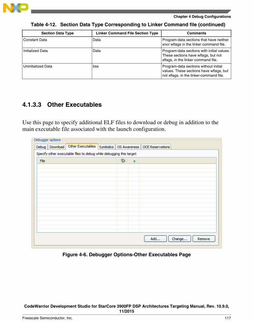
Table 4-12. Section Data Type Corresponding to Linker Command file (continued)
Section Data Type Linker Command File Section Type Comments
Constant Data Data Program-data sections that have neitherxnor wflags in the linker command file.
Initialized Data Data Program-data sections with initial values.These sections have wflags, but notxflags, in the linker command file.
Uninitialized Data bss Program-data sections without initialvalues. These sections have wflags, butnot xflags, in the linker-command file.
4.1.3.3 Other Executables
Use this page to specify additional ELF files to download or debug in addition to themain executable file associated with the launch configuration.
Figure 4-6. Debugger Options-Other Executables Page
Chapter 4 Debug Configurations
CodeWarrior Development Studio for StarCore 3900FP DSP Architectures Targeting Manual, Rev. 10.9.0,11/2015
Freescale Semiconductor, Inc. 117

The table below lists the various options available on the Other Executables page.
Table 4-13. Debugger Options - Other Executables
Option Description
File list Shows files and projects that the debugger uses during each debug session.
Debug column:• Checked-The debugger loads
symbolics for the file.• Cleared-The debugger does not
load symbolics for the file.
Download column:• Checked-The debugger
downloads the file to the TargetDevice.
• Cleared-The debugger does notdownload the file to the TargetDevice.
Add Click to open the Debug Other Executable dialog box, and add other executablefile to debug while debugging this target.
Use this dialog box to specify the following settings:
• Specify the location of the additional executable - Enter the path to theexecutable file that the debugger controls in addition to the current project'sexecutable file. Alternatively, click the Browse button to open a dialog boxthat you can use to specify the path.
• Load symbols - Check to have the debugger load symbols for the specifiedfile. Clear to prevent the debugger from loading the symbols. The Debugcolumn of the File list corresponds this setting.
• Download to device - Check to have the debugger download the specifiedfile to the target device. If you are debugging a Linux application, you canenter in the Specify the remote download path text box the path on thedevice to which you want to download the file.
NOTE: The Specify the remote download path option appliesjust to Linux application debugging; you should leavethe text box blank for all other types of debuggingsessions.
Clear the Download to device checkbox to prevent the debugger fromdownloading the file to the device. The Download column of the File listcorresponds to the Download to device setting.
• OK - Click to add the information that you specify in the Debug OtherExecutable dialog box to the File list.
Change Click to change the settings for the entry currently selected in the File list column.Change this information as needed, then click the OK button to update the entry inthe File list.
Remove Click to remove the entry currently selected in the File list.
4.1.3.4 Symbolics
Use this page to specify whether the IDE keeps symbolics in memory.
Using Debug Configurations Dialog Box
CodeWarrior Development Studio for StarCore 3900FP DSP Architectures Targeting Manual, Rev. 10.9.0,11/2015
118 Freescale Semiconductor, Inc.
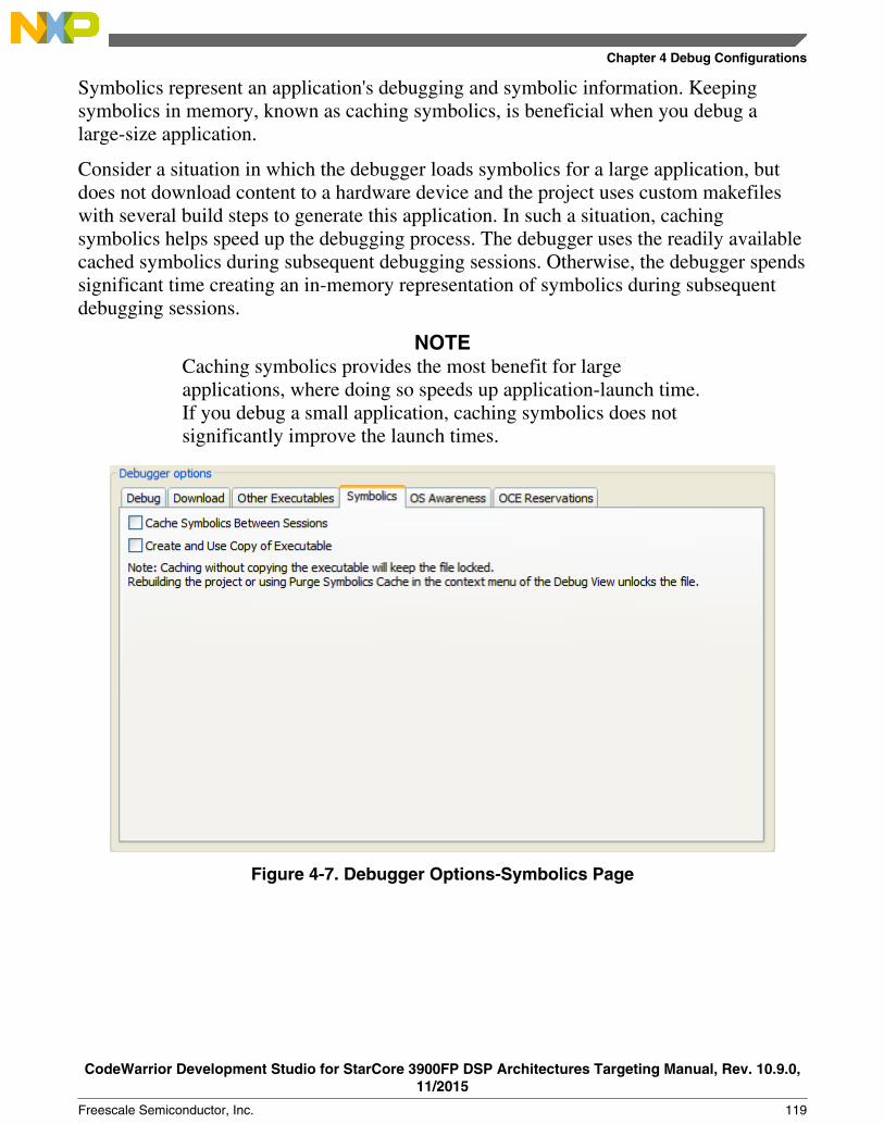
Symbolics represent an application's debugging and symbolic information. Keepingsymbolics in memory, known as caching symbolics, is beneficial when you debug alarge-size application.
Consider a situation in which the debugger loads symbolics for a large application, butdoes not download content to a hardware device and the project uses custom makefileswith several build steps to generate this application. In such a situation, cachingsymbolics helps speed up the debugging process. The debugger uses the readily availablecached symbolics during subsequent debugging sessions. Otherwise, the debugger spendssignificant time creating an in-memory representation of symbolics during subsequentdebugging sessions.
NOTECaching symbolics provides the most benefit for largeapplications, where doing so speeds up application-launch time.If you debug a small application, caching symbolics does notsignificantly improve the launch times.
Figure 4-7. Debugger Options-Symbolics Page
Chapter 4 Debug Configurations
CodeWarrior Development Studio for StarCore 3900FP DSP Architectures Targeting Manual, Rev. 10.9.0,11/2015
Freescale Semiconductor, Inc. 119

The table below lists the various options available on the Symbolics page.
Table 4-14. Debugger Options - Symbolics
Option Description
Cache Symbolics Between Sessions Check this option to have the debugger cache symbolics betweendebugging sessions. If you check this checkbox and clear the Create andUse Copy of Executable checkbox, the executable file remains lockedafter the debugging session ends. In the Debug view, right-click the lockedfile and select Un-target Executables to have the debugger delete itssymbolics cache and release the file lock. The IDE enables this menucommand when there are currently unused cached symbolics that it canpurge.
Clear this option so that the debugger does not cache symbolics betweendebugging sessions.
Create and Use Copy of Executable Check this option to have the debugger create and use a copy of theexecutable file. Using the copy helps avoid file-locking issues with thebuild system. If you check this checkbox, the IDE can build the executablefile in the background during a debugging session.
Clear this option so that the debugger does not create and use a copy ofthe executable file.
4.1.3.5 OS Awareness
Use this page to specify the operating system (OS) that resides on the target device.
Use the Target OS list box to specify the OS that runs on the target device, or specifyNone to have the debugger use the bareboard.
For more information, see the SmartDSP OS Concepts Guide.
Using Debug Configurations Dialog Box
CodeWarrior Development Studio for StarCore 3900FP DSP Architectures Targeting Manual, Rev. 10.9.0,11/2015
120 Freescale Semiconductor, Inc.
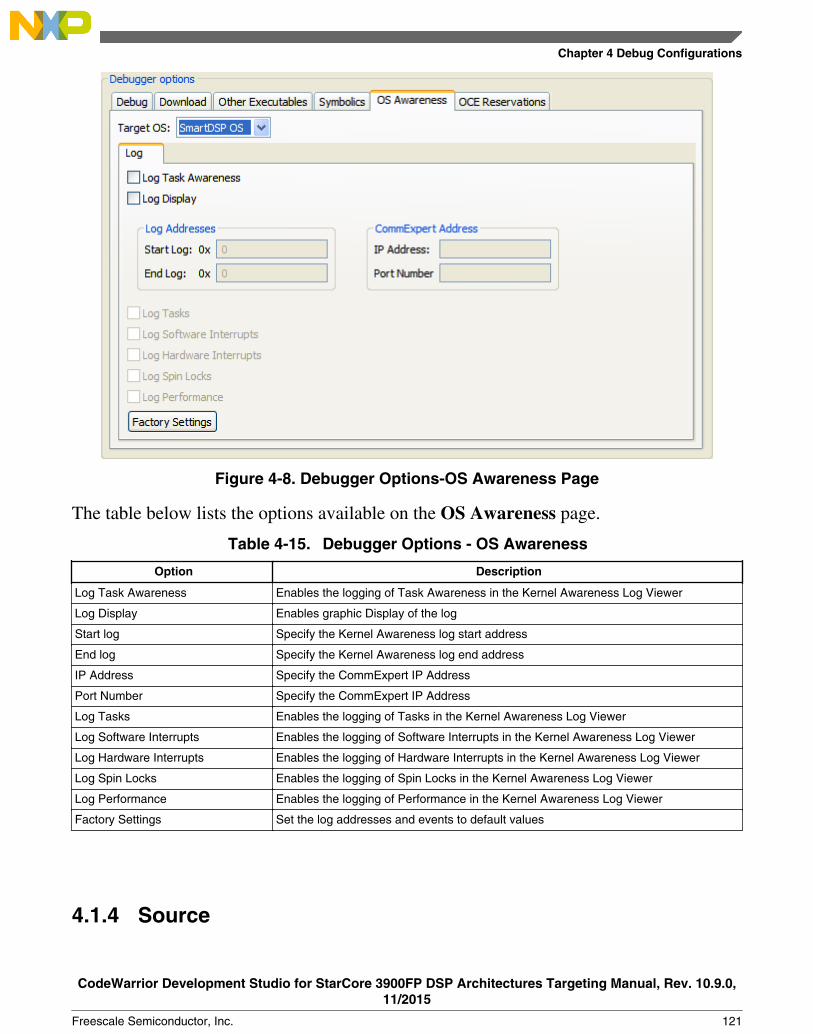
Figure 4-8. Debugger Options-OS Awareness Page
The table below lists the options available on the OS Awareness page.
Table 4-15. Debugger Options - OS Awareness
Option Description
Log Task Awareness Enables the logging of Task Awareness in the Kernel Awareness Log Viewer
Log Display Enables graphic Display of the log
Start log Specify the Kernel Awareness log start address
End log Specify the Kernel Awareness log end address
IP Address Specify the CommExpert IP Address
Port Number Specify the CommExpert IP Address
Log Tasks Enables the logging of Tasks in the Kernel Awareness Log Viewer
Log Software Interrupts Enables the logging of Software Interrupts in the Kernel Awareness Log Viewer
Log Hardware Interrupts Enables the logging of Hardware Interrupts in the Kernel Awareness Log Viewer
Log Spin Locks Enables the logging of Spin Locks in the Kernel Awareness Log Viewer
Log Performance Enables the logging of Performance in the Kernel Awareness Log Viewer
Factory Settings Set the log addresses and events to default values
4.1.4 Source
Chapter 4 Debug Configurations
CodeWarrior Development Studio for StarCore 3900FP DSP Architectures Targeting Manual, Rev. 10.9.0,11/2015
Freescale Semiconductor, Inc. 121

Use this tab to specify the location of source files used when debugging a C or C++application.
By default, this information is taken from the build path of your project.
Figure 4-9. Debug Configurations-Source Tab
The table below lists the various options available on the Source tab page.
Table 4-16. Source Tab Options
Option Description
Source Lookup Path Lists the source paths used to load an image after connectingthe debugger to the target.
Add Click to add new source containers to the Source LookupPath search list.
Edit Click to modify the content of the selected source container.
Remove Click to remove selected items from the Source LookupPath list.
Up Click to move selected items up the Source Lookup Pathlist.
Down Click to move selected items down the Source Lookup Pathlist.
Restore Default Click to restore the default source search list.
Table continues on the next page...
Using Debug Configurations Dialog Box
CodeWarrior Development Studio for StarCore 3900FP DSP Architectures Targeting Manual, Rev. 10.9.0,11/2015
122 Freescale Semiconductor, Inc.

Table 4-16. Source Tab Options (continued)
Option Description
Search for duplicate source files on the path Select to search for files with the same name on a selectedpath.
4.1.5 Environment
Use this tab to specify the environment variables and values to use when an applicationruns.
Figure 4-10. Debug Configurations-Environment Tab
The table below lists the various options available on the Environment tab page.
Table 4-17. Environment Tab Options
Option Description
Environment Variables to set Lists the environment variable name and its value.
New Click to create a new environment variable.
Table continues on the next page...
Chapter 4 Debug Configurations
CodeWarrior Development Studio for StarCore 3900FP DSP Architectures Targeting Manual, Rev. 10.9.0,11/2015
Freescale Semiconductor, Inc. 123
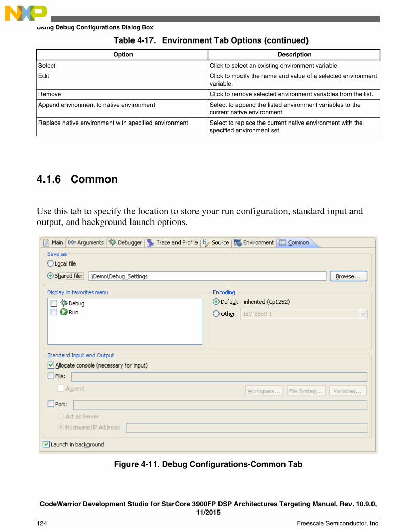
Table 4-17. Environment Tab Options (continued)
Option Description
Select Click to select an existing environment variable.
Edit Click to modify the name and value of a selected environmentvariable.
Remove Click to remove selected environment variables from the list.
Append environment to native environment Select to append the listed environment variables to thecurrent native environment.
Replace native environment with specified environment Select to replace the current native environment with thespecified environment set.
4.1.6 Common
Use this tab to specify the location to store your run configuration, standard input andoutput, and background launch options.
Figure 4-11. Debug Configurations-Common Tab
Using Debug Configurations Dialog Box
CodeWarrior Development Studio for StarCore 3900FP DSP Architectures Targeting Manual, Rev. 10.9.0,11/2015
124 Freescale Semiconductor, Inc.

The table below lists the various options available on the Common tab page.
Table 4-18. Common Tab Options
Option Description
Local file Select to save the launch configuration locally.
Shared file Select to specify the path of, or browse to, a workspace to store the launchconfiguration file, and be able to commit it to a repository.
Display in favorites menu Select to add the configuration name to Run or Debug menus for easy selection.
Console Encoding Select an encoding scheme to use for console output.
Allocate Console (necessary forinput)
Select to assign a console view to receive the output.
File Specify the file name to save output. .
Browse Workspace Specifies the path of, or browse to, a workspace to store the output file.
Browse File System Specifies the path of, or browse to, a file system directory to store the output file.
Variables Select variables by name to include in the output file.
Append Select to append output. Clear to recreate file each time.
Port Select to redirect standard output ( stdout, stderr) of a process being debugged toa user specified socket.
NOTE: You can also use the redirect command in debugger shell to redirectstandard output streams to a socket.
Act as Server Select to redirect the output from the current process to a local server socket bound tothe specified port.
Hostname/IP Address Select to redirect the output from the current process to a server socket located on thespecified host and bound to the specified port. The debugger will connect and write tothis server socket via a client socket created on an ephemeral port
Launch in background Select to launch configuration in background mode.
4.1.7 Trace and Profile
Use this page to configure the selected launch configuration for simulator and hardwareprofiling.
NOTETrace and Profile is available only for PACC and QDS targets.
Chapter 4 Debug Configurations
CodeWarrior Development Studio for StarCore 3900FP DSP Architectures Targeting Manual, Rev. 10.9.0,11/2015
Freescale Semiconductor, Inc. 125

Figure 4-12. Debug Configurations-Trace and Profile Tab (PACC Simulator Target)
The table listed below explains the Trace and Profile tab options for PACC simulatortargets.
Table 4-19. Trace and Profile Tab Options (PACC Simulator Target)
Option Description
Basic Tab
Enable logging Check Enable Logging checkbox if you want that a log file iscreated. The log file has details of the actions that takes placewhile collecting the trace data. For example, when the debugsession is terminated or when the target execution resumedor stopped.
Output Folder Specify the location of folder that will store the trace andprofile results.
Communication port number Used in TCP/IP communication between software analysisand CCSSIM2. You should choose the free port no. frominterval 0-65535.
Intermediate Tab
Automatically (when debug session starts) The trace collection process is started automatically when thedebug session is launched.
Manually (using debug toolbar trace buttons) This is the default behavior. This option is used when youwant to manually control the trace collection. The tracecollection process will not be started automatically on debugsession launch, but the trace configuration options areapplied, when you click on Start Trace Collection button.
Using Debug Configurations Dialog Box
CodeWarrior Development Studio for StarCore 3900FP DSP Architectures Targeting Manual, Rev. 10.9.0,11/2015
126 Freescale Semiconductor, Inc.

Figure 4-13. Debug Configurations - Trace and Profile Tab (QDS Hardware Target)
The table listed below explains the Trace and Profile tab options for the QDS hardwaretargets.
Table 4-20. Trace and Profile Tab Options (QDS Hardware Target)
Option Description
Basic Tab
Trace module configured by User Code Allows to do the trace settings in thecode without using the Trace and Profilepage of Debug launch.
CodeWarrior Allows to do the trace settings usingTrace and Profile page of Debug launch
Trace Scenario Profiling - L2 cache events Trace values of counters of both triad Aand B on subroutine/interrupt call/returninstructions
Profiling - data loads Trace values of counters of both triad Aand B on subroutine/interrupt call/returninstructions
Profiling - clock cycles Trace values of counters of triad A onsubroutine/interrupt call/returninstructions
Table continues on the next page...
Chapter 4 Debug Configurations
CodeWarrior Development Studio for StarCore 3900FP DSP Architectures Targeting Manual, Rev. 10.9.0,11/2015
Freescale Semiconductor, Inc. 127

Table 4-20. Trace and Profile Tab Options (QDS Hardware Target) (continued)
Option Description
Profiling - advanced Traces each change of flow instructions
Program trace Trace values of counters of both triad Aand B on subroutine/interrupt call/returninstructions
Coverage For C source lines, displays thepercentage of number of assemblyinstructions executed from the totalnumber of assembly instructionscorresponding to the source line. Forassembly source lines, it shows if theinstructions were executed or not
None Traces only subroutine/interrupt call/return instructions
Extend Trace Scenario with: Ownership Trace Traces information on current task ID.Ownership trace facilitates tracking theactive operating system task byproviding visibility to the special purposeregisters designated for use by the OSfor process ID
User defined events Traces any write to TMDAT and TMTAGcore registers
Bandwidth Each default trace scenario has aspecific bandwidth. The bandwidthindicates how many messages arerouted in trace stream, on hardware,depending on used trace scenario tocollect trace
Intermediate Tab
Trace collection One Buffer When the buffer is full, tracing stops, butnot the target.
Overwrite Continue to write trace to buffer byoverwriting old records in buffer - circularbuffer.
Continuos Collects trace continuously till yoususpend the target application.
Location NPC Buffer Saves trace data in NPC internal buffer.
Gigabit TAP + Trace Saves trace data in probe buffer.
Probe buffer size (bytes) Specifies the size of the probe buffer.
DDR buffer Saves trace data in DDR. Magenta is thebus that transfers trace data from NPCinternal buffer to DDR.
Buffer start address Specifies the start address of the DDRwhere trace data is saved.
Buffer size Specifies the DDR memory size of theregion used as trace buffer.
Use settings from LCF file Uses trace buffer start address and sizefrom linker files. File common.l3kcontains _TRACE_BUFFER_size and
Table continues on the next page...
Using Debug Configurations Dialog Box
CodeWarrior Development Studio for StarCore 3900FP DSP Architectures Targeting Manual, Rev. 10.9.0,11/2015
128 Freescale Semiconductor, Inc.

Table 4-20. Trace and Profile Tab Options (QDS Hardware Target) (continued)
Option Description
_TRACE_BUFFER_start variables thatallow you to change the start addressand size. File mmu_attr.l3k contains_ENABLE_TB variable that allows toenable and disable settings for tracebuffer from linker's files.
Trace Control Settings Allows you to specify trace configurationsettings.
Automatically (when debug sessionstarts)
The trace collection process is startedautomatically when the debug session islaunched.
Manually (using debug toolbar tracebuttons)
This is the default behavior. This optionis used when you want to manuallycontrol the trace collection. The tracecollection process will not be startedautomatically on debug session launch,but the trace configuration options areapplied, when you click on the StartTrace Collection button.
Advanced Tab
Triad Settings Triad A In the Advanced tab, you need toconfigure triad settings if you haveselected Profile trace checkbox inCustomize Trace Scenario. Afterselecting Profile trace checkbox, thedefault profiling events are mapped onTriad A - L1 Icache Access Sorting andTriad B - Program L1 L2 CacheableAccess Sorting.
Triad B
NOTEFor more details about the Trace and Profile tab options, seethe CodeWarrior Development Studio for StarCore SC3900FPDSP Architectures Tracing and Analysis Tools User Guide.
4.2 Customizing Debug Configurations
When you use the CodeWarrior wizard to create a new project, the wizard sets theproject's launch configurations to default values.
You can change the default values of your project's launch configurations, according toyour program's requirements.
To modify the launch configurations:
Chapter 4 Debug Configurations
CodeWarrior Development Studio for StarCore 3900FP DSP Architectures Targeting Manual, Rev. 10.9.0,11/2015
Freescale Semiconductor, Inc. 129

1. Start the CodeWarrior IDE.2. From the main menu bar of the IDE, select Run > Debug Configurations.
The Debug Configurations dialog box appears. The left side of this dialog box has alist of debug configurations that apply to the current application.
3. Expand the CodeWarrior configuration.4. From the expanded list, select the debug configuration that you want to modify.
The follwoing figure shows the Debug Configurations dialog box with the settingsfor the debug configuration you selected.
Figure 4-14. Debug Configurations Dialog Box5. In the group of tabs in the upper-right side of the dialog box, click a tab.6. Change the settings on the debug configuration page as per your requirements. See
Using Debug Configurations Dialog Box for details on the various settings of thispage.
7. Click Apply to save the new settings.
When you finish, you can click Debug to start a new debugging session, or click Close tosave your changes and close the Debug Configurations dialog box.
Customizing Debug Configurations
CodeWarrior Development Studio for StarCore 3900FP DSP Architectures Targeting Manual, Rev. 10.9.0,11/2015
130 Freescale Semiconductor, Inc.

4.3 Reverting Debug Configuration Settings
After making some modifications in a debug configuration's settings, you can either savethe pending (unsaved) changes or revert to last saved settings.
To save the pending changes, click the Apply button of the Debug Configurationsdialog box, or click the Close button and then the Yes button.
To undo pending changes and restore the last saved settings, click the Revert button atthe bottom of the Debug Configurations dialog box.
The IDE restores the last set of saved settings to all pages of the Debug Configurationsdialog box. Also, the IDE disables the Revert button until you make new pendingchanges.
Chapter 4 Debug Configurations
CodeWarrior Development Studio for StarCore 3900FP DSP Architectures Targeting Manual, Rev. 10.9.0,11/2015
Freescale Semiconductor, Inc. 131

Reverting Debug Configuration Settings
CodeWarrior Development Studio for StarCore 3900FP DSP Architectures Targeting Manual, Rev. 10.9.0,11/2015
132 Freescale Semiconductor, Inc.

Chapter 5Working with Debugger
This chapter explains various aspects of CodeWarrior debugging, such as debugging aproject, configuring connections, setting breakpoints and watchpoints, working withregisters, viewing memory, viewing cache, and debugging externally built executablefiles.
NOTEThis chapter documents debugger features that are specific toCodeWarrior Development Studio for StarCore 3900FP DSPArchitectures. For more information on debugger features thatare common in all CodeWarrior products, see CodeWarriorDevelopment Studio Common Features Guide.
This chapter explains:
• Debugging a CodeWarrior project• Configuring Connections• Editing remote system configuration• Working with Breakpoints• Working with Watchpoints• Working with Registers• Viewing memory• Viewing Cache• Changing Program Counter Value• Hard resetting• Per Core Reset• Setting Stack Depth• Import a CodeWarrior Executable file Wizard• Debugging Externally Built Executable Files
CodeWarrior Development Studio for StarCore 3900FP DSP Architectures Targeting Manual, Rev. 10.9.0,11/2015
Freescale Semiconductor, Inc. 133

5.1 Debugging a CodeWarrior project
This section explains how to debug a CodeWarrior project.
This section describes the following two ways of debugging a CodeWarrior project:
• Debugging Project Using Simulator• Debugging Project using Target Hardware
5.1.1 Debugging Project Using Simulator
This section describes how to debug a project using simulator.
To debug a CodeWarrior project using a simulator, follow these steps:
1. Select the project you want to debug in the CodeWarrior Projects view.2. From the CodeWarrior IDE menu bar, select Run > Debug Configurations.
The Debug Configurations dialog box appears, as shown in the figure below.
Debugging a CodeWarrior project
CodeWarrior Development Studio for StarCore 3900FP DSP Architectures Targeting Manual, Rev. 10.9.0,11/2015
134 Freescale Semiconductor, Inc.

Figure 5-1. Debug Configurations Dialog Box3. Select the required launch configuration, for example B4860-
Sim_Debug_B4860_Download_core00.
You can also debug the B4860 simulator projects using the B4860 instruction setsimulator (ISS) supported on Linux 64-bit operating system.
a. In the Connection area, click Edit.
The Properties for <project> dialog box appears (shown in the figure below).
b. Select CCSSIM2 ISS from the Connection type drop-down list.c. In the Connection tab, select the Manual Launch option.d. Specify the IP address of the Linux 64-bit machine, CCSSIM2 is started on, in
the Server hostname/IP text box.
NOTEFor information about launching simulator on a LinuxPC, see "Creating, Building, and Debugging a Project"section in CodeWarrior for StarCore 3900FP DSPs -Windows Edition Quick Start.
Chapter 5 Working with Debugger
CodeWarrior Development Studio for StarCore 3900FP DSP Architectures Targeting Manual, Rev. 10.9.0,11/2015
Freescale Semiconductor, Inc. 135

e. Specify the port number used while launching the CCSSIM2 in the Server portnumber text box.
Figure 5-2. Properties for <Project> Dialog Boxf. Click OK.
4. Configure the launch configuration settings, using the various tabs available in theDebug Configurations dialog box.
5. Click Debug.
The debugger downloads your program to the selected core, switches to the Debugperspective, and halts execution at first statement of main().
6. Similarly, download your program to all the other cores.
The Debug view displays all the threads associated with the cores.
7. Click Multicore Resume in the Debug view (see the figure below) to resume allcores.
Debugging a CodeWarrior project
CodeWarrior Development Studio for StarCore 3900FP DSP Architectures Targeting Manual, Rev. 10.9.0,11/2015
136 Freescale Semiconductor, Inc.

Figure 5-3. Multi-core Debugging - Resume All Cores8. Select Run > Multicore Terminate.
NOTEFor details on multi-core debugging, see the Multi-CoreDebugging chapter.
The debugger terminates the active debug session. The threads associated with eachcore in the Debug view disappear.
You just finished debugging a simulator project.
5.1.2 Debugging Project using Target Hardware
This section describes how to debug a project using target hardware.
To debug a CodeWarrior project using target hardware, follow these steps:
Chapter 5 Working with Debugger
CodeWarrior Development Studio for StarCore 3900FP DSP Architectures Targeting Manual, Rev. 10.9.0,11/2015
Freescale Semiconductor, Inc. 137
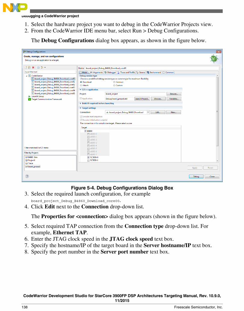
1. Select the hardware project you want to debug in the CodeWarrior Projects view.2. From the CodeWarrior IDE menu bar, select Run > Debug Configurations.
The Debug Configurations dialog box appears, as shown in the figure below.
Figure 5-4. Debug Configurations Dialog Box3. Select the required launch configuration, for example
board_project_Debug_B4860_Download_core00.4. Click Edit next to the Connection drop-down list.
The Properties for <connection> dialog box appears (shown in the figure below).
5. Select required TAP connection from the Connection type drop-down list. Forexample, Ethernet TAP.
6. Enter the JTAG clock speed in the JTAG clock speed text box.7. Specify the hostname/IP of the target board in the Server hostname/IP text box.8. Specify the port number in the Server port number text box.
Debugging a CodeWarrior project
CodeWarrior Development Studio for StarCore 3900FP DSP Architectures Targeting Manual, Rev. 10.9.0,11/2015
138 Freescale Semiconductor, Inc.
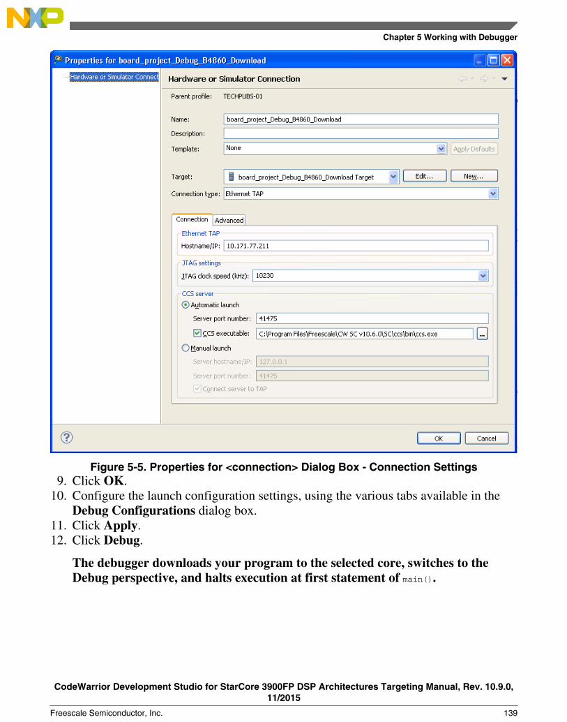
Figure 5-5. Properties for <connection> Dialog Box - Connection Settings9. Click OK.
10. Configure the launch configuration settings, using the various tabs available in theDebug Configurations dialog box.
11. Click Apply.12. Click Debug.
The debugger downloads your program to the selected core, switches to theDebug perspective, and halts execution at first statement of main().
Chapter 5 Working with Debugger
CodeWarrior Development Studio for StarCore 3900FP DSP Architectures Targeting Manual, Rev. 10.9.0,11/2015
Freescale Semiconductor, Inc. 139
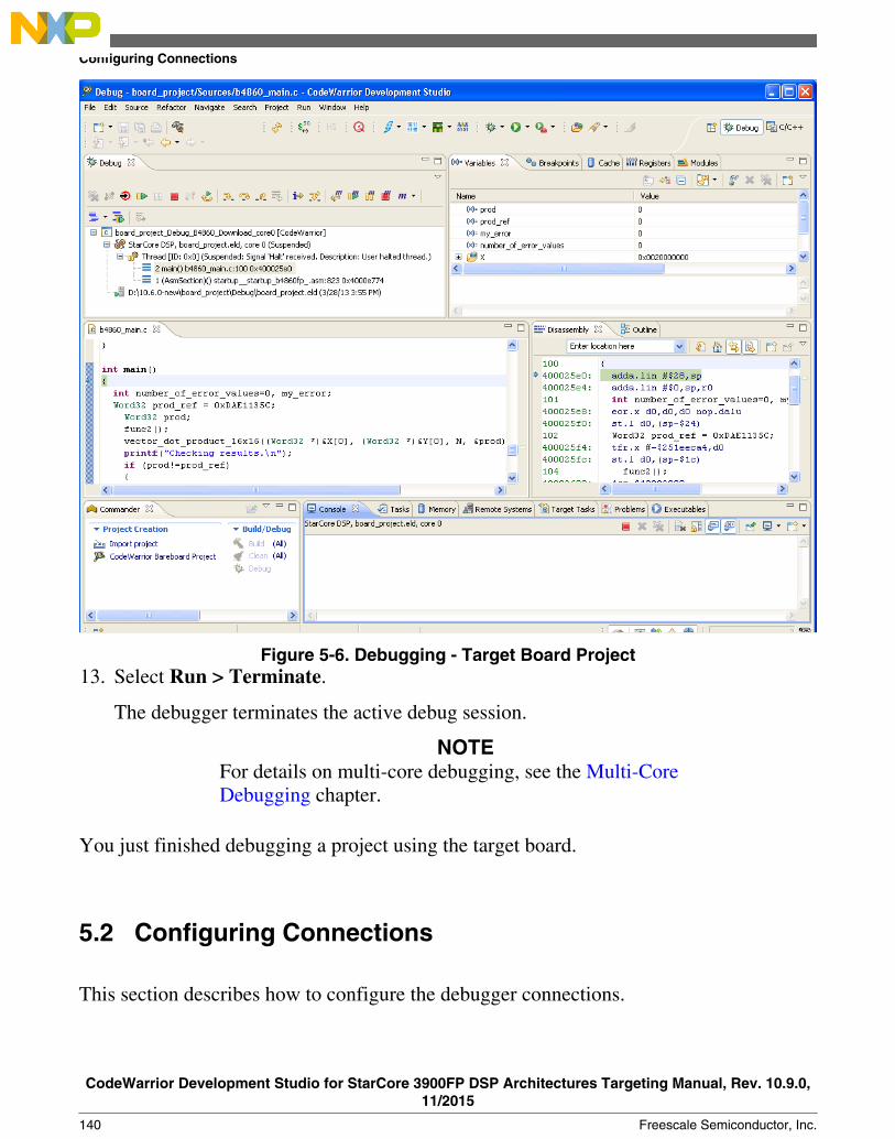
Figure 5-6. Debugging - Target Board Project13. Select Run > Terminate.
The debugger terminates the active debug session.
NOTEFor details on multi-core debugging, see the Multi-CoreDebugging chapter.
You just finished debugging a project using the target board.
5.2 Configuring Connections
This section describes how to configure the debugger connections.
Configuring Connections
CodeWarrior Development Studio for StarCore 3900FP DSP Architectures Targeting Manual, Rev. 10.9.0,11/2015
140 Freescale Semiconductor, Inc.

The CodeWarrior debugger can communicate with StarCore devices in several ways. Thetable below lists each StarCore device along with the protocols the debugger can use tocommunicate with that device.
Table 5-1. Debugger Communication Protocols for StarCore Devices
Device family StarCore device CCS Simulator TAP
Qonverge B4060 QDS
B4420 QDS
B4420 ISS
B4460 QDS
B4860 QDS
B4860 ISS
G4860 QDS
SC3900 SC3900fp Platform ISS
SC3900fp PlatformPACC
In this section:
• CodeWarrior Connection Server• Connection types
5.2.1 CodeWarrior Connection Server
The CodeWarrior Connection Server (CCS) provides a TCP/IP connection point fordebugger communications.
If you run a CCS instance on your computer, remote instances of the CodeWarriordebugger can access each target board connected to your system. Similarly, each instanceof the CodeWarrior debugger can access the target boards connected to each remotecomputer that runs a CCS instance.
In this section:
• Running CCS
Chapter 5 Working with Debugger
CodeWarrior Development Studio for StarCore 3900FP DSP Architectures Targeting Manual, Rev. 10.9.0,11/2015
Freescale Semiconductor, Inc. 141

• Displaying CCS Console• Configuring CCS
5.2.1.1 Running CCS
Each time you debug a project that uses a local CCS connection, the CodeWarrior IDEautomatically starts CCS if it is not running already. Also, you can run CCS yourselffrom this location, where <CWInstallDir> is the path to your CodeWarrior installation:
<CWInstallDir>\ccs\bin\ccs.exe
If CCS is running, the icon appears in the Windows® taskbar. Right-click this icon todisplay the CCS context menu. The menu has these commands:
• Show Console: Displays the CCS console• Hide Console: Hides the CCS console• About CCS: Displays version information• Quit CCS: Terminates CCS
5.2.1.2 Displaying CCS Console
The CodeWarrior Connection Server (CCS) console allows you to view and changeserver-connection options. You can issue commands by typing them into the command-line window or by selecting options from the console's menus.
To display CCS console, follow these steps:
1. Run <CWInstallDir>\ccs\bin\ccs.exe, where <CWInstallDir> is the path to yourCodeWarrior installation.
CCS starts and the icon appears in the Windows® taskbar.
2. Right-click the CCS icon and select Show console from the context menu.
The CodeWarrior Connection Server console appears, as shown in the figurebelow.
Configuring Connections
CodeWarrior Development Studio for StarCore 3900FP DSP Architectures Targeting Manual, Rev. 10.9.0,11/2015
142 Freescale Semiconductor, Inc.

Figure 5-7. CodeWarrior Connection Server Console
5.2.1.3 Configuring CCS
CodeWarrior Connection Server uses parallel port 1 to communicate with a target deviceand listens for commands on port 41475. The CCS connection configuration can be setup using the ccs.cfg file. CCS reads ccs.cfg for start up commands to configure theconnection. ccs.cfg is located in <CWInstallDir>\ccs\bin\. To change these default settings,follow these steps:
1. Run <CWInstallDir>\ccs\bin\ccs.exe, where <CWInstallDir> is the path to yourCodeWarrior installation.
CCS starts and the icon appears in the Windows® taskbar.
2. Right-click the CCS icon and select Show console from the context menu.
The CodeWarrior Connection Server console appears.
3. At the console command prompt, issue these commands:a. delete all
This command deletes the current CCS configuration.
b. config cc
where cc can be:
• parallel:<#>• lpt (same as parallel)• epp:<#>
Chapter 5 Working with Debugger
CodeWarrior Development Studio for StarCore 3900FP DSP Architectures Targeting Manual, Rev. 10.9.0,11/2015
Freescale Semiconductor, Inc. 143

• usb
• powertap:<ipaddr>• wiretap:<#>• lspusb
This command defines the command converter that CCS uses.
c. config port port_num
where port_num is the port on which CCS listens for commands. The defaultCCS port number is 41475.
4. Right click the CCS icon.
The CCS context menu appears.
5. Select Quit CCS from this menu.
CodeWarrior Connection Server console exits.
NOTEAny changes you make to the CCS configuration arepermanent. They persist from one CCS session to the next.
You have modified the default CCS settings.
5.2.2 Connection types
This section describes the different connection types provided by CodeWarrior debuggerfor connecting the target board to a computer.
The connection types supported by CodeWarrior debugger are:
• CCSSIM2 ISS• CCSSIM2 PACC• Ethernet TAP• Gigabit TAP + Trace• Gigabit TAP• USB TAP• CodeWarrior TAP
Configuring Connections
CodeWarrior Development Studio for StarCore 3900FP DSP Architectures Targeting Manual, Rev. 10.9.0,11/2015
144 Freescale Semiconductor, Inc.

5.2.2.1 CCSSIM2 ISS
Select this connection type to connect to simulators based on the CCSSIM2 ISS interface.
To configure the settings of the CCSSIM2 ISS connection type, perform the followingsteps:
1. Select Run > Debug Configurations.
The Debug Configurations dialog box appears.
2. In the Connection group, click Edit next to the Connection drop-down list.
The Properties for <connection launch configuration> window appears.
3. Select CCSSIM2 ISS from the Connection type drop-down list.
The Connection and Advanced tabs display options with respect to the settings ofthe selected connection type.
The table below describes various options available on the Connection tab page.
Table 5-2. CCSSIM2 ISS - Connection Tab Options
Option Description
CCS server Automatic launch Select to automatically launch the specified CCSserver on the specified port.
Server port number Specifies the port number to launch the CCSserver on.
CCS executable Select to specify the path of, or browse to, theexecutable file of the CCS server.
Manual launch Select to manually launch the specified CCSserver on the specified port.
Server hostname/IP Specifies hostname or the IP address of the CCSserver.
Server port number Specifies the port number to launch the CCSserver on.
The table below describes the various options available on the Advanced tab page.
Table 5-3. CCSSIM2 ISS - Advanced Tab Options
Option Description
Target connection lost settings Try to reconnect If this option is selected, the lost CCS connectionbetween the target and host is reset. Select theTimeout checkbox to specify the time interval (inseconds) after which the connection will be lost.
Table continues on the next page...
Chapter 5 Working with Debugger
CodeWarrior Development Studio for StarCore 3900FP DSP Architectures Targeting Manual, Rev. 10.9.0,11/2015
Freescale Semiconductor, Inc. 145

Table 5-3. CCSSIM2 ISS - Advanced Tab Options (continued)
Option Description
Terminate the debug session If this option is selected, the debug session isterminated and the lost connection betweenJTAG and CCS server is not reset.
Ask me This is the default setting. If the CCS connectionis lost between the target and host, the user isasked if the connection needs to be reset orterminated.
Advanced CCS settings CCS timeout Specifies the CCS timeout period. If the targetdoes not respond in the provided time-interval,you receive a CCS timeout error.
Enable logging Select to display protocol logging in console.
5.2.2.2 CCSSIM2 PACC
Select this connection type to connect to simulators based on the CCSSIM2 PACCinterface.
NOTECCSSIM2 PACC connection is available only for the SC3900fptarget.
To configure the settings of the CCSSIM2 PACC connection type, perform thefollowing steps:
1. Select Run > Debug Configurations.
The Debug Configurations window appears.
2. In the Connection group, click the Edit button next to the Connection drop-downlist.
The Properties for <connection launch configuration> window appears.
3. Select CCSSIM2 PACC from the Connection type drop-down list.
The Connection and Advanced tabs display options with respect to the settings ofthe selected connection type.
The table below describes various options available on the Connection tab page.
Configuring Connections
CodeWarrior Development Studio for StarCore 3900FP DSP Architectures Targeting Manual, Rev. 10.9.0,11/2015
146 Freescale Semiconductor, Inc.

Table 5-4. CCSSIM2 PACC - Connection Tab Options
Option Description
CCS Server Automatic launch Select to automatically launch the specified CCSserver on the specified port.
Server port number Specifies the port number to launch the CCSserver on.
CCS executable Select to specify the path of, or browse to, theexecutable file of the CCS server.
Manual launch Select to manually launch the specified CCSserver on the specified port.
Server hostname/IP Specifies hostname or the IP address of the CCSserver.
Server port number Specifies the port number to launch the CCSserver on.
The table below describes the various options available on the Advanced tab page.
Table 5-5. CCSSIM2 PACC - Advanced Tab Options
Option Description
Target connection lost settings Try to reconnect If this option is selected, the lost CCS connectionbetween the target and host is reset. Select theTimeout checkbox to specify the time interval (inseconds) after which the connection will be lost.
Terminate the debug session If this option is selected, the debug session isterminated and the lost connection betweenJTAG and CCS server is not reset.
Ask me This is the default setting. If the CCS connectionis lost between the target and host, the user isasked if the connection needs to be reset orterminated.
Advanced CCS settings CCS timeout Specifies the CCS timeout period. If the targetdoes not respond in the provided time-interval,you receive a CCS timeout error.
Enable logging Select to display protocol logging in console.
5.2.2.3 Ethernet TAP
The CodeWarrior and Ethernet TAP and USB TAP hardware use emulation technologyto control and provide visibility into your target system. They let you control and debugsoftware running in-target, with minimal intrusion into target operation. You use theOnCE connector on your target hardware to interface with the TAP hardware.
Chapter 5 Working with Debugger
CodeWarrior Development Studio for StarCore 3900FP DSP Architectures Targeting Manual, Rev. 10.9.0,11/2015
Freescale Semiconductor, Inc. 147

Select this connection type when Ethernet network is used as interface to communicatewith the hardware device.
To configure the settings of an Ethernet TAP connection type, perform the followingsteps:
1. Select Run > Debug Configurations.
The Debug Configurations dialog box appears.
2. In the Connection group, click Edit next to the Connection drop-down list.
The Properties for <connection launch configuration> window appears.
3. Select the Ethernet TAP from the Connection type drop-down list.
The Connection and Advanced tabs display options with respect to the settings ofthe selected connection type.
The table below describes various options available on the Connection tab page.
Table 5-6. Ethernet TAP - Connection Tab Options
Option Description
Ethernet TAP Hostname/IP Specifies hostname or the IP address of the TAP.
JTAG settings JTAG clock speed (kHz) Specifies the JTAG clock speed.
CCS server Automatic launch Select to automatically launch the specified CCSserver on the specified port.
Server port number Specifies the port number to launch the CCSserver on.
CCS executable Click to specify the path of, or browse to, theexecutable file of the CCS server.
Manual launch Select to manually launch the specified CCSserver on the specified port.
Server hostname/IP Specifies hostname or the IP address of the CCSserver.
Server port number Specifies the port number to launch the CCSserver on.
Connect server to TAP Select to enable the CCS server to connect tothe TAP.
The table below describes the various options available on the Advanced tab page.
Table 5-7. Ethernet TAP - Advanced Tab Options
Option Description
Target connection lost settings Try to reconnect If this option is selected, the lost CCS connectionbetween the target and host is reset. Select the
Table continues on the next page...
Configuring Connections
CodeWarrior Development Studio for StarCore 3900FP DSP Architectures Targeting Manual, Rev. 10.9.0,11/2015
148 Freescale Semiconductor, Inc.

Table 5-7. Ethernet TAP - Advanced Tab Options (continued)
Option Description
Timeout checkbox to specify the time interval (inseconds) after which the connection will be lost.
Terminate the debug session If this option is selected, the debug session isterminated and the lost connection betweenJTAG and CCS server is not reset.
Ask me This is the default setting. If the CCS connectionis lost between the target and host, the user isasked if the connection needs to be reset orterminated.
Advanced CCS settings CCS timeout Specifies the CCS timeout period. If the targetdoes not respond in the provided time-interval,you receive a CCS timeout error.
Enable logging Select to display protocol logging in console.
JTAG config file This panel displays the JTAG configuration filebeing used. This panel is populated only if youhave selected a JTAG configuration file for yourproject. If a JTAG configuration file is notselected, this panel displays a None value. Formore details on JTAG configuration files, seeCreating a JTAG Initialization File and SettingLaunch Configurations.
Advanced TAP settings Force shell download Select to force a reload of the TAP shellsoftware.
5.2.2.4 Gigabit TAP + Trace
Select this connection type when Gigabit TAP and Trace is used as interface tocommunicate with the hardware device.
To configure the settings of a Gigabit TAP + Trace connection type, perform thefollowing steps:
1. Select Run > Debug Configurations.
The Debug Configurations dialog box appears.
2. In the Connection group, click Edit next to the Connection drop-down list.
The Properties for <connection launch configuration> window appears.
3. Select the Gigabit TAP + Trace from the Connection type drop-down list.
The Connection and Advanced tabs display the options with respect to the settingsof the selected connection type.
Chapter 5 Working with Debugger
CodeWarrior Development Studio for StarCore 3900FP DSP Architectures Targeting Manual, Rev. 10.9.0,11/2015
Freescale Semiconductor, Inc. 149

The table below describes various options available on the Connection tab page.
Table 5-8. Gigabit TAP + Trace - Connection Tab Options
Option Description
Gigabit TAP + Trace Hostname/IP Specifies hostname or the IP address of the TAP.
Debug connection Specifies the type of debug connection to use.The options available are JTAG over JTAG cableconnection, JTAG over Aurora cable connection,and Aurora connection.
JTAG settings JTAG clock speed (kHz) Specifies the JTAG clock speed.
Aurora settings Aurora data rate Specifies the Aurora data rate, which refers tothe frequency with which the raw data bits aretransferred on the wire. The Aurora connection isused only for trace analysis.
Receive lanes Select to specify the Aurora receive lane settings.
Transmit lanes Select to specify the Aurora transmit lanesettings.
CCS server Automatic launch Select to automatically launch the specified CCSserver on the specified port.
Server port number Specifies the port number to launch the CCSserver on.
CCS executable Select to specify the path of, or browse to, theexecutable file of the CCS server.
Manual launch Select to manually launch the specified CCSserver on the specified port.
Server hostname/IP Specifies hostname or the IP address of the CCSserver.
Server port number Specifies the port number to launch the CCSserver on.
Connect server to TAP Select to enable the CCS server to connect tothe TAP.
The table below describes the various options available on the Advanced tab page.
Table 5-9. Gigabit TAP + Trace - Advanced Tab Options
Option Description
Target connection lost settings Try to reconnect If this option is selected, the lost CCS connectionbetween the target and host is reset. Select theTimeout checkbox to specify the time interval (inseconds) after which the connection will be lost.
Terminate the debug session If this option is selected, the debug session isterminated and the lost connection betweenJTAG and CCS server is not reset.
Ask me This is the default setting. If the CCS connectionis lost between the target and host, the user isasked if the connection needs to be reset orterminated.
Table continues on the next page...
Configuring Connections
CodeWarrior Development Studio for StarCore 3900FP DSP Architectures Targeting Manual, Rev. 10.9.0,11/2015
150 Freescale Semiconductor, Inc.

Table 5-9. Gigabit TAP + Trace - Advanced Tab Options (continued)
Option Description
Advanced CCS settings CCS timeout Specifies the CCS timeout period. If the targetdoes not respond in the provided time-interval,you receive a CCS timeout error.
Enable logging Select to display protocol logging in console.
JTAG config file This panel displays the JTAG configuration filebeing used. This panel is populated only if youhave selected a JTAG configuration file for yourproject. If a JTAG configuration file is notselected, this panel displays a None value. Formore details on JTAG configuration files, seeCreating a JTAG Initialization File and SettingLaunch Configurations.
Advanced TAP settings Force shell download Select to force a reload of the TAP shellsoftware.
5.2.2.5 Gigabit TAP
Select this connection type when Gigabit TAP is used as interface to communicate withthe hardware device.
To configure the settings of a Gigabit TAP connection type, perform the following steps:
1. Select Run > Debug Configurations.
The Debug Configurations dialog box appears.
2. In the Connection group, click Edit next to the Connection drop-down list.
The Properties for <connection launch configuration> window appears.
3. Select the Gigabit TAP from the Connection type drop-down list.
The Connection and Advanced tabs display options with respect to the settings ofthe selected connection type.
The table below describes various options available on the Connection tab page.
Table 5-10. Gigabit TAP - Connection Tab Options
Option Description
Gigabit TAP Hostname/IP Specifies hostname or the IP address of the TAP.
JTAG settings JTAG clock speed (kHz) Specifies the JTAG clock speed.
Table continues on the next page...
Chapter 5 Working with Debugger
CodeWarrior Development Studio for StarCore 3900FP DSP Architectures Targeting Manual, Rev. 10.9.0,11/2015
Freescale Semiconductor, Inc. 151

Table 5-10. Gigabit TAP - Connection Tab Options (continued)
Option Description
CCS server Automatic launch Select to automatically launch the specified CCSserver on the specified port.
Server port number Specifies the port number to launch the CCSserver on.
CCS executable Click to specify the path of, or browse to, theexecutable file of the CCS server.
Manual launch Select to manually launch the specified CCSserver on the specified port.
Server hostname/IP Specifies hostname or the IP address of the CCSserver.
Server port number Specifies the port number to launch the CCSserver on.
Connect server to TAP Select to enable the CCS server to connect tothe TAP.
The table below describes the various options available on the Advanced tab page.
Table 5-11. Gigabit TAP - Advanced Tab Options
Option Description
Target connection lost settings Try to reconnect If this option is selected, the lost CCS connectionbetween the target and host is reset. Select theTimeout checkbox to specify the time interval (inseconds) after which the connection will be lost.
Terminate the debug session If this option is selected, the debug session isterminated and the lost connection betweenJTAG and CCS server is not reset.
Ask me This is the default setting. If the CCS connectionis lost between the target and host, the user isasked if the connection needs to be reset orterminated.
Advanced CCS settings CCS timeout Specifies the CCS timeout period. If the targetdoes not respond in the provided time-interval,you receive a CCS timeout error.
Enable logging Select to display protocol logging in console.
JTAG config file This panel displays the JTAG configuration filebeing used. This panel is populated only if youhave selected a JTAG configuration file for yourproject. If a JTAG configuration file is notselected, this panel displays a None value. Formore details on JTAG configuration files, seeCreating a JTAG Initialization File and SettingLaunch Configurations.
Advanced TAP settings Force shell download Select to force a reload of the TAP shellsoftware.
Configuring Connections
CodeWarrior Development Studio for StarCore 3900FP DSP Architectures Targeting Manual, Rev. 10.9.0,11/2015
152 Freescale Semiconductor, Inc.
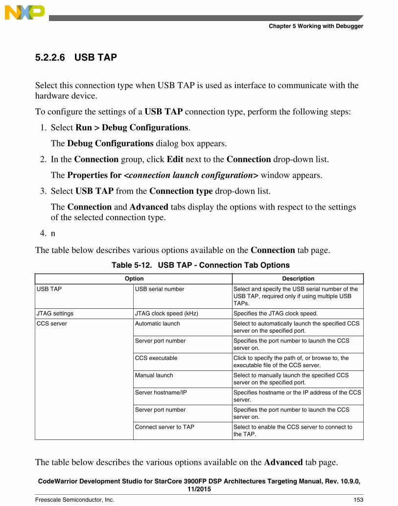
5.2.2.6 USB TAP
Select this connection type when USB TAP is used as interface to communicate with thehardware device.
To configure the settings of a USB TAP connection type, perform the following steps:
1. Select Run > Debug Configurations.
The Debug Configurations dialog box appears.
2. In the Connection group, click Edit next to the Connection drop-down list.
The Properties for <connection launch configuration> window appears.
3. Select USB TAP from the Connection type drop-down list.
The Connection and Advanced tabs display the options with respect to the settingsof the selected connection type.
4. n
The table below describes various options available on the Connection tab page.
Table 5-12. USB TAP - Connection Tab Options
Option Description
USB TAP USB serial number Select and specify the USB serial number of theUSB TAP, required only if using multiple USBTAPs.
JTAG settings JTAG clock speed (kHz) Specifies the JTAG clock speed.
CCS server Automatic launch Select to automatically launch the specified CCSserver on the specified port.
Server port number Specifies the port number to launch the CCSserver on.
CCS executable Click to specify the path of, or browse to, theexecutable file of the CCS server.
Manual launch Select to manually launch the specified CCSserver on the specified port.
Server hostname/IP Specifies hostname or the IP address of the CCSserver.
Server port number Specifies the port number to launch the CCSserver on.
Connect server to TAP Select to enable the CCS server to connect tothe TAP.
The table below describes the various options available on the Advanced tab page.
Chapter 5 Working with Debugger
CodeWarrior Development Studio for StarCore 3900FP DSP Architectures Targeting Manual, Rev. 10.9.0,11/2015
Freescale Semiconductor, Inc. 153

Table 5-13. USB TAP - Advanced Tab Options
Option Description
Target connection lost settings Try to reconnect If this option is selected, the lost CCS connectionbetween the target and host is reset. Select theTimeout checkbox to specify the time interval (inseconds) after which the connection will be lost.
Terminate the debug session If this option is selected, the debug session isterminated and the lost connection betweenJTAG and CCS server is not reset.
Ask me This is the default setting. If the CCS connectionis lost between the target and host, the user isasked if the connection needs to be reset orterminated.
Advanced CCS settings CCS timeout Specifies the CCS timeout period. If the targetdoes not respond in the provided time-interval,you receive a CCS timeout error.
Enable logging Select to display protocol logging in console.
JTAG config file This panel displays the JTAG configuration filebeing used. This panel is populated only if youhave select a JTAG configuration file for yourproject. If a JTAG configuration file is notselected, this panel displays a None value. Formore details on JTAG configuration files, seeCreating a JTAG Initialization File and SettingLaunch Configurations.
Advanced TAP settings Force shell download Select to force a reload of the TAP shellsoftware.
5.2.2.7 CodeWarrior TAP
Select this connection type when either the CodeWarrior TAP is used as interface tocommunicate with the hardware device.
To configure the settings of a CodeWarrior TAP connection type, perform thefollowing steps:
1. Select Run > Debug Configurations.
The Debug Configurations dialog box appears.
2. In the Connection group, click Edit next to the Connection drop-down list.
The Properties for <connection launch configuration> window appears.
3. Select CodeWarrior TAP from the Connection type drop-down list.
Configuring Connections
CodeWarrior Development Studio for StarCore 3900FP DSP Architectures Targeting Manual, Rev. 10.9.0,11/2015
154 Freescale Semiconductor, Inc.

The Connection and Advanced tabs display the options with respect to the settingsof the selected connection type.
The table below describes various options available on the Connection tab page.
Table 5-14. CodeWarrior TAP - Connection Tab Options
Option Description
CodeWarrior TAP Hardware Connection Specifies CodeWarrior TAP interface tocommunicate with the hardware device.CodeWarrior TAP supports both USB andEthernet network interfaces.
Hostname/IP Specifies hostname or the IP address of the TAP.
NOTE: Enabled only if Hardware Connectionis set to Ethernet.
Serial Number Select and specify the USB serial number of theUSB TAP; required only if using multipleCodeWarror TAPs (over USB).
NOTE: Enabled only if Hardware Connectionis set to USB.
JTAG settings JTAG clock speed (kHz) Specifies the JTAG clock speed.
CCS server Automatic launch Select to automatically launch the specified CCSserver on the specified port.
Server port number Specifies the port number to launch the CCSserver on.
CCS executable Click to specify the path of, or browse to, theexecutable file of the CCS server.
Manual launch Select to manually launch the specified CCSserver on the specified port.
Server hostname/IP Specifies hostname or the IP address of the CCSserver.
Server port number Specifies the port number to launch the CCSserver on.
Connect server to TAP Select to enable the CCS server to connect tothe CodeWarrior TAP.
The table below describes the various options available on the Advanced tab page.
Table 5-15. CodeWarrior TAP - Advanced Tab Options
Option Description
Target connection lost settings Try to reconnect If this option is selected, the lost CCS connectionbetween the target and host is reset. Select theTimeout checkbox to specify the time interval (inseconds) after which the connection will be lost.
Terminate the debug session If this option is selected, the debug session isterminated and the lost connection betweenJTAG and CCS server is not reset.
Table continues on the next page...
Chapter 5 Working with Debugger
CodeWarrior Development Studio for StarCore 3900FP DSP Architectures Targeting Manual, Rev. 10.9.0,11/2015
Freescale Semiconductor, Inc. 155

Table 5-15. CodeWarrior TAP - Advanced Tab Options (continued)
Option Description
Ask me This is the default setting. If the CCS connectionis lost between the target and host, the user isasked if the connection needs to be reset orterminated.
Advanced CCS settings CCS timeout Specifies the CCS timeout period. If the targetdoes not respond in the provided time-interval,you receive a CCS timeout error.
Enable logging Select to display protocol logging in console.
JTAG config file This panel displays the JTAG configuration filebeing used. This panel is populated only if youhave select a JTAG configuration file for yourproject. If a JTAG configuration file is notselected, this panel displays a None value. Formore details on JTAG configuration files, seeCreating a JTAG Initialization File and SettingLaunch Configurations.
Advanced TAP settings Force shell download Select to force a reload of the TAP shellsoftware.
You can connect to the CodeWarrior TAP connection using two options:• CodeWarrior TAP - JTAG Connection through USB• CodeWarrior TAP - JTAG Connection through Ethernet
5.2.2.7.1 CodeWarrior TAP - JTAG Connection through USB
This section describes how to connect to a board using the CodeWarrior TAP – JTAGphysical connection through USB.
To connect perform the following steps:
1. Select Run > Debug Configurations.
The Debug Configurations dialog box appears.
2. In the Connection group, click Edit next to the Connection drop-down list.
The Properties for <connection launch configuration> dialog box appears.
3. Select CodeWarrior TAP from the Connection type drop-down list.4. Select USB from the Hardware connection drop-down list.5. If you have more than one target connected to your machine through USB, then you
have specify the serial number of the device for the connection, for this check thecorresponding checkbox and specify the correct serial number in the text box (Figure5-8).
Configuring Connections
CodeWarrior Development Studio for StarCore 3900FP DSP Architectures Targeting Manual, Rev. 10.9.0,11/2015
156 Freescale Semiconductor, Inc.

NOTEThe CodeWarrior TAP USB serial number is its MACaddress.
Figure 5-8. CodeWarrior TAP - USB Connection6. Configures the JTAG speed and the advanced CCS settings as per the requirement.7. Validate the settings.8. Selects the new connection in the launch configuration and starts the debug session.
NOTEThe connection through JTAG interface through USB has thesame settings as the CodeWarrior USB TAP connection.
5.2.2.7.2 CodeWarrior TAP - JTAG Connection through Ethernet
This section describes how to connect to a board using the CodeWarrior TAP – JTAGphysical connection through Ethernet.
To connect the board, perform the following steps:
1. Select Run > Debug Configurations.
The Debug Configurations dialog box appears.
2. In the Connection group, click Edit next to the Connection drop-down list.
The Properties for <connection launch configuration> dialog box appears.
3. Select CodeWarrior TAP from the Connection type drop-down list.4. Select Ethernet from the Hardware connection drop-down list.
Chapter 5 Working with Debugger
CodeWarrior Development Studio for StarCore 3900FP DSP Architectures Targeting Manual, Rev. 10.9.0,11/2015
Freescale Semiconductor, Inc. 157
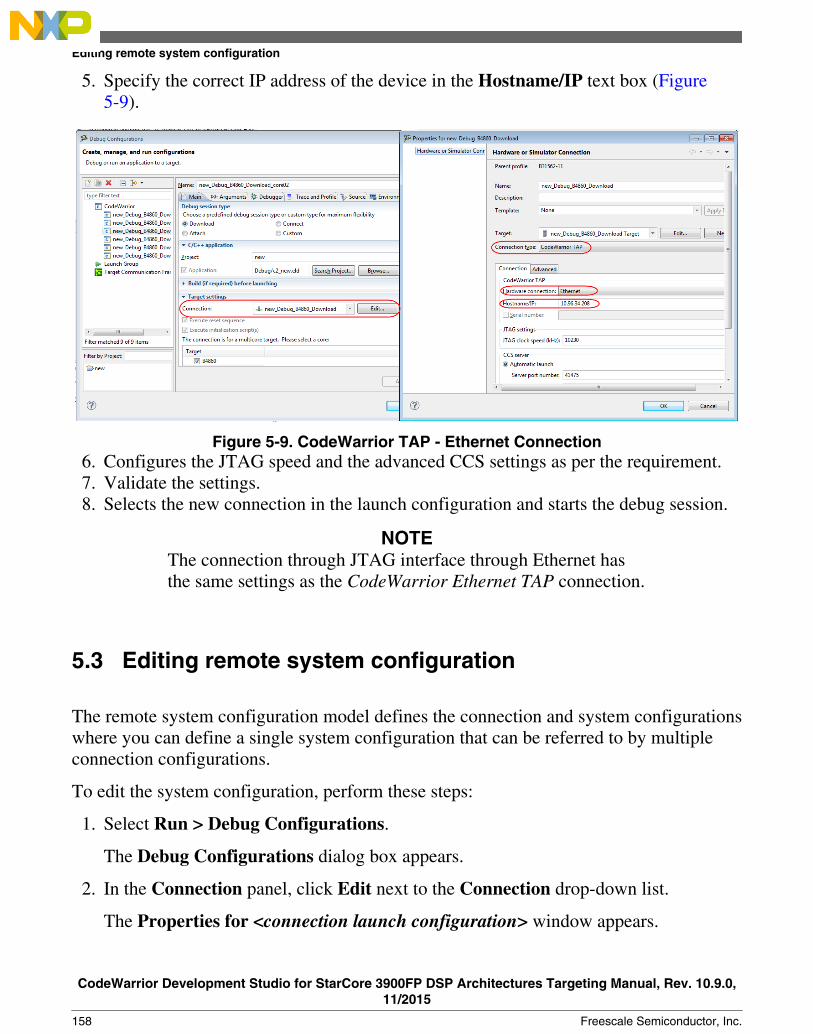
5. Specify the correct IP address of the device in the Hostname/IP text box (Figure5-9).
Figure 5-9. CodeWarrior TAP - Ethernet Connection6. Configures the JTAG speed and the advanced CCS settings as per the requirement.7. Validate the settings.8. Selects the new connection in the launch configuration and starts the debug session.
NOTEThe connection through JTAG interface through Ethernet hasthe same settings as the CodeWarrior Ethernet TAP connection.
5.3 Editing remote system configuration
The remote system configuration model defines the connection and system configurationswhere you can define a single system configuration that can be referred to by multipleconnection configurations.
To edit the system configuration, perform these steps:
1. Select Run > Debug Configurations.
The Debug Configurations dialog box appears.
2. In the Connection panel, click Edit next to the Connection drop-down list.
The Properties for <connection launch configuration> window appears.
Editing remote system configuration
CodeWarrior Development Studio for StarCore 3900FP DSP Architectures Targeting Manual, Rev. 10.9.0,11/2015
158 Freescale Semiconductor, Inc.

3. Click Edit next to the Target drop-down list.
The Properties for <system launch configuration> window appears.
4. Select the appropriate system type from the Target type drop-down list.5. Make the respective settings in Initialization tab, Memory tab, I/O Model Tab and
Advanced tab.6. Click OK to save the settings.7. Click OK to close the Properties window.
In this section:
• Initialization tab• Memory tab• I/O Model Tab• Advanced tab
5.3.1 Initialization tab
Use the Initialization tab to specify target initialization file for various cores.
Figure 5-10. Initialization tab
The table below lists the various options available on the Initialization tab page.
Chapter 5 Working with Debugger
CodeWarrior Development Studio for StarCore 3900FP DSP Architectures Targeting Manual, Rev. 10.9.0,11/2015
Freescale Semiconductor, Inc. 159
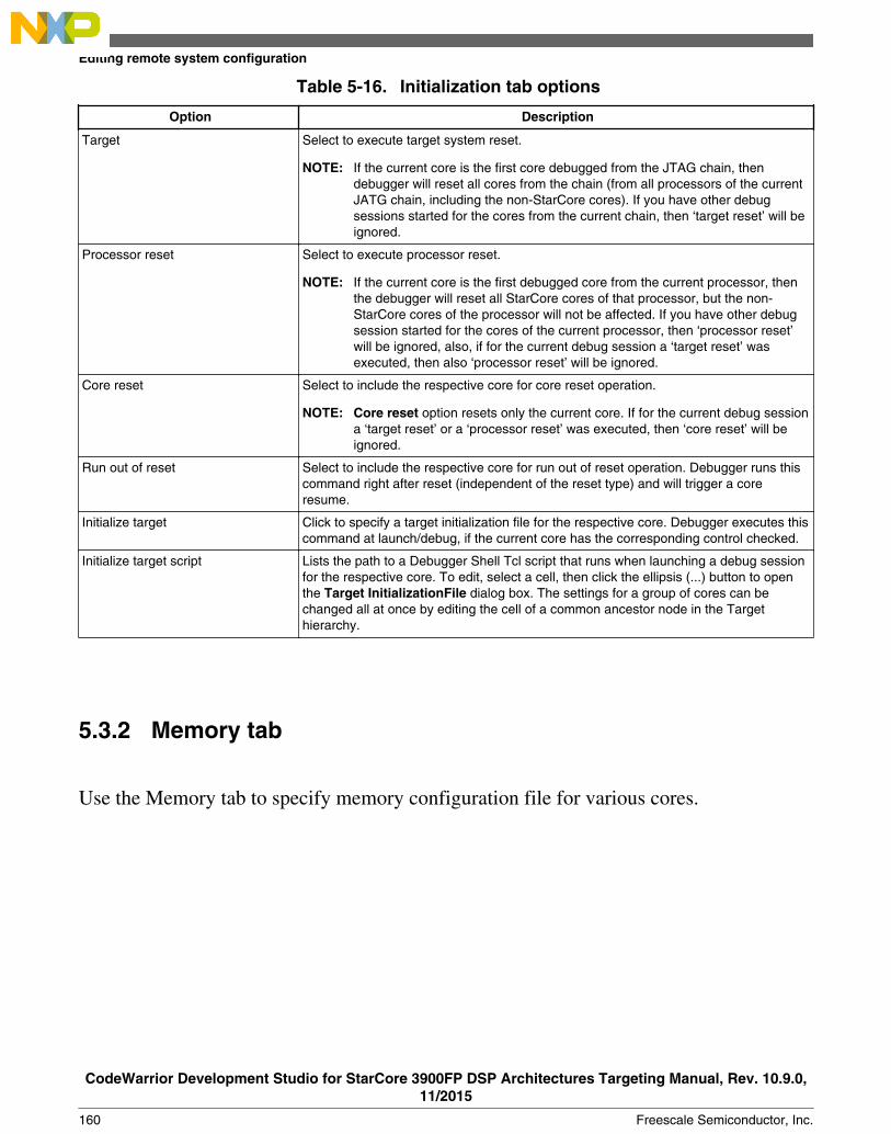
Table 5-16. Initialization tab options
Option Description
Target Select to execute target system reset.
NOTE: If the current core is the first core debugged from the JTAG chain, thendebugger will reset all cores from the chain (from all processors of the currentJATG chain, including the non-StarCore cores). If you have other debugsessions started for the cores from the current chain, then ‘target reset’ will beignored.
Processor reset Select to execute processor reset.
NOTE: If the current core is the first debugged core from the current processor, thenthe debugger will reset all StarCore cores of that processor, but the non-StarCore cores of the processor will not be affected. If you have other debugsession started for the cores of the current processor, then ‘processor reset’will be ignored, also, if for the current debug session a ‘target reset’ wasexecuted, then also ‘processor reset’ will be ignored.
Core reset Select to include the respective core for core reset operation.
NOTE: Core reset option resets only the current core. If for the current debug sessiona ‘target reset’ or a ‘processor reset’ was executed, then ‘core reset’ will beignored.
Run out of reset Select to include the respective core for run out of reset operation. Debugger runs thiscommand right after reset (independent of the reset type) and will trigger a coreresume.
Initialize target Click to specify a target initialization file for the respective core. Debugger executes thiscommand at launch/debug, if the current core has the corresponding control checked.
Initialize target script Lists the path to a Debugger Shell Tcl script that runs when launching a debug sessionfor the respective core. To edit, select a cell, then click the ellipsis (...) button to openthe Target InitializationFile dialog box. The settings for a group of cores can bechanged all at once by editing the cell of a common ancestor node in the Targethierarchy.
5.3.2 Memory tab
Use the Memory tab to specify memory configuration file for various cores.
Editing remote system configuration
CodeWarrior Development Studio for StarCore 3900FP DSP Architectures Targeting Manual, Rev. 10.9.0,11/2015
160 Freescale Semiconductor, Inc.

Figure 5-11. Memory tab
The table below lists the various options available on the Memory tab page.
Table 5-17. Memory tab options
Option Description
Target Lists the targets and the supported cores.
Memory configuration Select to specify a memory configuration file for the respective core.
Memory configuration file Lists the path to the memory configuration file for the respective core. To edit, select acell, then click the ellipsis button to open the Memory Configuration File dialog box.The settings for a group of cores can be changed all at once by editing the cell of acommon ancestor node in the Target hierarchy.
5.3.3 I/O Model TabUse the I/O Model tab to specify the I/O support option for the selected target (shown inthe figure below).
Chapter 5 Working with Debugger
CodeWarrior Development Studio for StarCore 3900FP DSP Architectures Targeting Manual, Rev. 10.9.0,11/2015
Freescale Semiconductor, Inc. 161
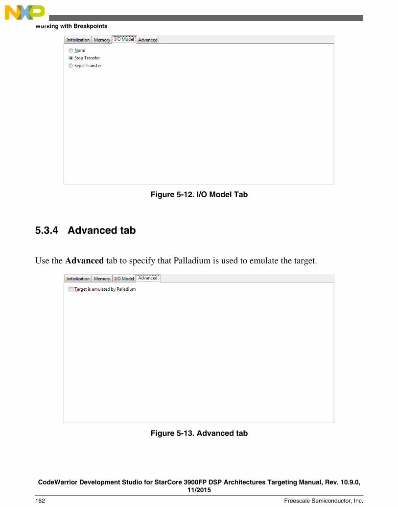
Figure 5-12. I/O Model Tab
5.3.4 Advanced tab
Use the Advanced tab to specify that Palladium is used to emulate the target.
Figure 5-13. Advanced tab
Working with Breakpoints
CodeWarrior Development Studio for StarCore 3900FP DSP Architectures Targeting Manual, Rev. 10.9.0,11/2015
162 Freescale Semiconductor, Inc.

5.4 Working with Breakpoints
A breakpoint is set on an executable line of a program; if the breakpoint is enabled whenyou debug, the execution suspends before that line of code executes.
The different breakpoint types that you can set are listed below:
• Software breakpoints: The debugger sets a software breakpoint into target memory.When program execution reaches the breakpoint, the processor stops and activatesthe debugger. The breakpoint remains in the target memory until the user removes it.
The breakpoint can only be set in writable memory, such as SRAM or DDR. Youcannot use this type of breakpoints in ROM.
• Hardware breakpoints: Selecting the Hardware menu option causes the debugger touse the internal processor breakpoints. These breakpoints are usually very few andcan be used with all types of memories (ROM/RAM) because they are implementedby using processor registers.
TipYou can also set breakpoint types by issuing the bpcommand in the Debugger Shell view.
In this section:
• Setting Breakpoints• Setting Hardware Breakpoints• Removing Breakpoints• Removing Hardware Breakpoints
5.4.1 Setting Breakpoints
This section explains how to set breakpoints within a program in CodeWarrior IDE.
To set a breakpoint, perform the following steps:
1. Switch to the Debug perspective in CodeWarrior IDE.2. Open the Debug view if it is not already open by selecting Window > Show View >
Debug.
The Debug view appears, shown in the figure below.
Chapter 5 Working with Debugger
CodeWarrior Development Studio for StarCore 3900FP DSP Architectures Targeting Manual, Rev. 10.9.0,11/2015
Freescale Semiconductor, Inc. 163

Figure 5-14. Debug View3. Expand the Thread group.4. Under the Thread group, select the thread that has the main() function.
The source code appears in the Editor view (shown in the figure below). The smallblue arrow to the left of the source code indicates which code statement theprocessor's program counter is set to execute next.
Figure 5-15. Editor View5. In the Editor view, place the cursor on the line that has this statement: printf("Output
%d\n",DataOut[i]);
6. Select Run > Toggle Line Breakpoint.
Working with Breakpoints
CodeWarrior Development Studio for StarCore 3900FP DSP Architectures Targeting Manual, Rev. 10.9.0,11/2015
164 Freescale Semiconductor, Inc.

A blue dot appears in the marker bar to the left of the line (shown in the figurebelow). This dot indicates an enabled breakpoint. After the debugger installs thebreakpoint, a blue checkmark appears beside the dot. The debugger installs abreakpoint by loading into the Java™ virtual machine the code in which you set thatbreakpoint.
TipAn alternate way to set a breakpoint is to double-click themarker bar to the left of any source-code line. If you set thebreakpoint on a line that does not have an executablestatement, the debugger moves the breakpoint to the closestsubsequent line that has an executable statement. Themarker bar shows the installed breakpoint location. If youwant to set a hardware breakpoint instead of a softwarebreakpoint, use the bp command in the Debugger Shellview. You can also right-click on the marker bar to the leftof any source-code line, and select Set Special Breakpointfrom the context menu that appears.
Figure 5-16. Editor View - After Setting Breakpoints7. From the menu bar, select Run > Resume.
The debugger executes all lines up to, but not including, the line at which you set thebreakpoint. The editor view highlights the line at which the debugger suspendedexecution.
Chapter 5 Working with Debugger
CodeWarrior Development Studio for StarCore 3900FP DSP Architectures Targeting Manual, Rev. 10.9.0,11/2015
Freescale Semiconductor, Inc. 165

5.4.2 Setting Hardware Breakpoints
This section explains how to set hardware breakpoints within a program in CodeWarriorIDE.
There are two ways to set hardware breakpoints:
• Using IDE to Set Hardware Breakpoints• Using Debugger Shell to Set Hardware Breakpoints
5.4.2.1 Using IDE to Set Hardware Breakpoints
To set a hardware breakpoint using the IDE, follow these steps:
1. In the CodeWarrior IDE, select Run > Breakpoint Types > C/C++ HardwareBreakpoints.
2. In the Editor view, click in the source line where you want to place the breakpoint.3. Select Run > Toggle Breakpoint.
A hardware breakpoint appears in the marker bar on the left side of the source line.
5.4.2.2 Using Debugger Shell to Set Hardware Breakpoints
You can use the Debugger Shell view to set hardware breakpoints. Follow these steps toset a hardware breakpoint using the Debugger Shell view:
1. Open the Debugger Shell view.2. Begin the command line with the text:
bp -hw
3. Complete the command line by specifying the function, address, or file at which youwant to set the hardware breakpoint.
For example, to set a breakpoint for line 6 in your program, type:
bp -hw 6
4. Press the Enter key.
The debugger shell executes the command and sets the hardware breakpoint.
Working with Breakpoints
CodeWarrior Development Studio for StarCore 3900FP DSP Architectures Targeting Manual, Rev. 10.9.0,11/2015
166 Freescale Semiconductor, Inc.

TipEnter help bp at the command-line prompt to see examplesof the bp command syntax and usage.
5.4.3 Removing Breakpoints
This section explains how to remove breakpoints from a program in CodeWarrior IDE.
To remove a breakpoint from your program, you have two options:
• Remove Breakpoints using Marker Bar• Remove Breakpoints using Breakpoints View
5.4.3.1 Remove Breakpoints using Marker Bar
To remove an existing breakpoint using the marker bar, follow these steps:
1. Right-click the breakpoint in the marker bar.2. Select Toggle Breakpoint from the menu that appears.
5.4.3.2 Remove Breakpoints using Breakpoints View
To remove an existing breakpoint using the Breakpoints view, follow these steps:
1. Open the Breakpoints view if it is not already open by selecting Window > ShowView > Breakpoints.
The Breakpoints view appears, displaying a list of breakpoints.
2. Right-click on the breakpoint you wish to remove and select Remove from the menuthat appears (shown in the figure below).
The selected breakpoint is removed, and it disappears from the both the marker barand the list in the view.
NOTETo remove all of the breakpoints from the program at once,select Remove All from the menu.
Chapter 5 Working with Debugger
CodeWarrior Development Studio for StarCore 3900FP DSP Architectures Targeting Manual, Rev. 10.9.0,11/2015
Freescale Semiconductor, Inc. 167

Figure 5-17. Removing Breakpoint
5.4.4 Removing Hardware Breakpoints
This section explains how to remove hardware breakpoints from a program inCodeWarrior IDE.
There are two ways to remove existing hardware breakpoints:
• Remove Hardware Breakpoints using the IDE• Remove Hardware Breakpoints using Debugger Shell
5.4.4.1 Remove Hardware Breakpoints using the IDE
To remove a hardware breakpoint, follow these steps:
1. Right-click on the existing breakpoint in the marker bar.2. Select Toggle Breakpoint from the menu that appears.
Alternatively, you can remove the breakpoint from the Breakpoints view, using thefollowing steps:
Working with Breakpoints
CodeWarrior Development Studio for StarCore 3900FP DSP Architectures Targeting Manual, Rev. 10.9.0,11/2015
168 Freescale Semiconductor, Inc.

1. Open the Breakpoints view if it is not already open by choosing Window > ShowView > Breakpoints.
The Breakpoints view appears, displaying a list of breakpoints.
2. Right-click on the hardware breakpoint you wish to remove and select Remove fromthe menu that appears.
The selected breakpoint is removed, and it disappears from the both the marker barand the list in the view.
5.4.4.2 Remove Hardware Breakpoints using Debugger Shell
To remove a hardware breakpoint using the Debugger Shell view, follow these steps:
1. Open the debugger shell.2. Begin the command line with the text:
bp -hw
3. Complete the command line by specifying the function, address, or file at which youwant to remove the hardware breakpoint.
For example, to remove a breakpoint at line 6 in your program, type:
bp -hw 6 off
4. Press the Enter key.
The debugger shell executes the command and removes the hardware breakpoint.
5.5 Working with Watchpoints
A watchpoint is another name for a data breakpoint that you can set on an address or arange of addresses in the memory.
The debugger halts execution each time the watchpoint location is read, written, oraccessed (read or written). You can set a watchpoint using the Add Watchpoint dialogbox. To open the Add Watchpoint dialog box, use one of the following views:
• Breakpoints view• Memory view• Variables view
Chapter 5 Working with Debugger
CodeWarrior Development Studio for StarCore 3900FP DSP Architectures Targeting Manual, Rev. 10.9.0,11/2015
Freescale Semiconductor, Inc. 169

The debugger handles both watchpoints and breakpoints in similar manners. You can usethe Breakpoints view to manage both watchpoints and breakpoints. It means, you canuse the Breakpoints view to add, remove, enable, and disable both watchpoints andbreakpoints. The debugger attempts to set the watchpoint if a session is in progress basedon the active debugging context (the active context is the selected project in the Debugview).
If the debugger sets the watchpoint when no debugging session is in progress, or when re-starting a debugging session, the debugger attempts to set the watchpoint at startup as itdoes for breakpoints. The Problems view displays error messages when the debuggerfails to set a watchpoint. For example, if you set watchpoints on overlapping memoryranges, or if a watchpoint falls out of execution scope, an error message appears in theProblems view. You can use this view to see additional information about the error.
The following sections explain how to set or remove watchpoints:
• Setting Watchpoints• Removing Watchpoints
5.5.1 Setting Watchpoints
Use the Add Watchpoint dialog box to create a watchpoint for a memory range. You canspecify these parameters for a watchpoint:
• An address (including memory space)• An expression that evaluates to an address• A memory range• An access type on which to trigger
To open the Add Watchpoint dialog box, follow these steps:
1. Open the Debug perspective.2. Click one of these tabs:
• Breakpoints• Memory• Variables
The corresponding view appears.
Working with Watchpoints
CodeWarrior Development Studio for StarCore 3900FP DSP Architectures Targeting Manual, Rev. 10.9.0,11/2015
170 Freescale Semiconductor, Inc.

3. Right-click the appropriate content inside the view as mentioned in the table below.
Table 5-18. Opening the Add Watchpoint dialogbox
In the View... Right-Click...
Breakpoints An empty area inside the view.
Memory The cell or range of cells on which you want to set the watchpoint.
Variables A global variable.
NOTEThe debugger does not support setting a watchpoint on astack variable or a register variable. Setting a watchpoint ona local variable may result in halt of execution atunexpected locations.
4. Select Add Watchpoint (C/C++) from the context menu that appears.
The Add Watchpoint dialog box appears (shown in the figure below). The debuggersets the watchpoint according to the settings that you specify in the Add Watchpointdialog box. The Breakpoints view shows information about the newly setwatchpoint. The Problems view shows error messages when the debugger fails to setthe watchpoint.
Figure 5-18. Add Watchpoint Dialog Box
The table below describes the options available in the Add Watchpoint dialog box.
Chapter 5 Working with Debugger
CodeWarrior Development Studio for StarCore 3900FP DSP Architectures Targeting Manual, Rev. 10.9.0,11/2015
Freescale Semiconductor, Inc. 171
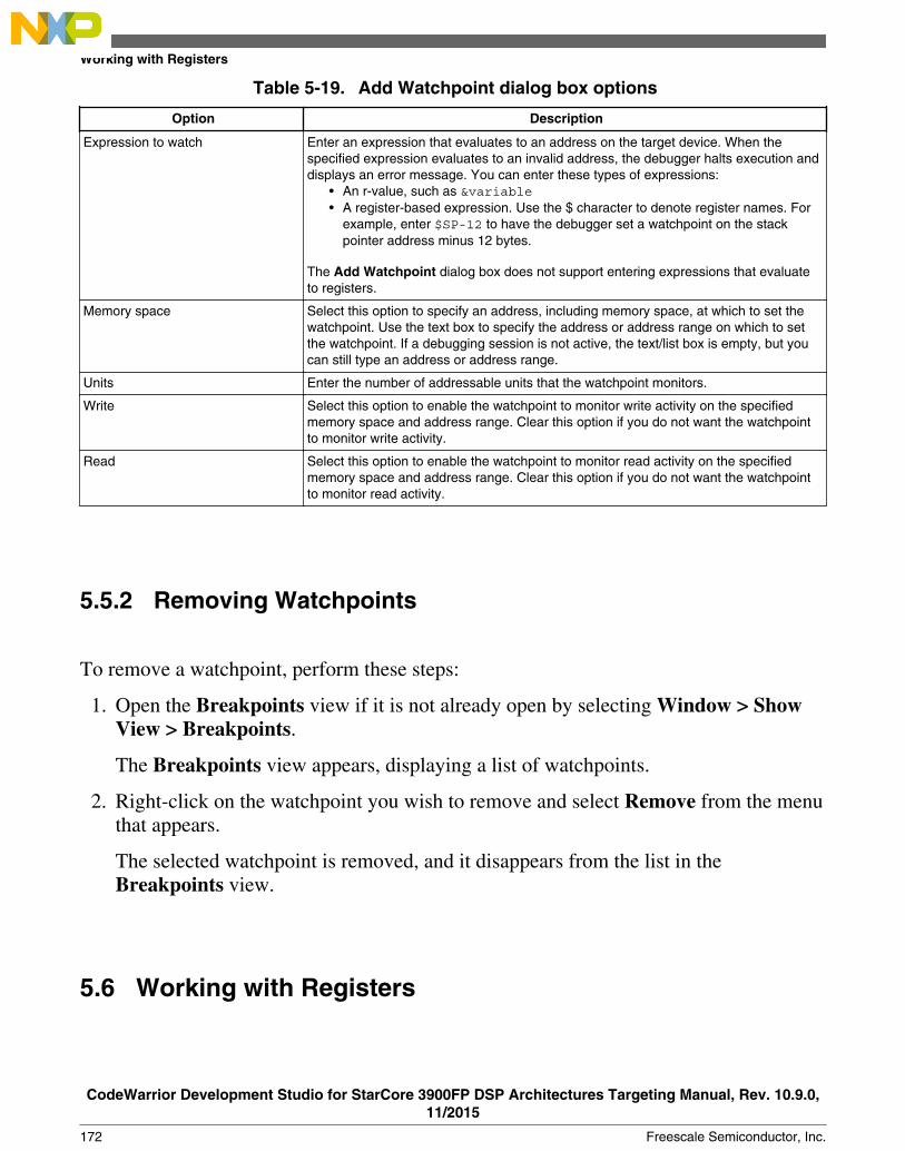
Table 5-19. Add Watchpoint dialog box options
Option Description
Expression to watch Enter an expression that evaluates to an address on the target device. When thespecified expression evaluates to an invalid address, the debugger halts execution anddisplays an error message. You can enter these types of expressions:
• An r-value, such as &variable• A register-based expression. Use the $ character to denote register names. For
example, enter $SP-12 to have the debugger set a watchpoint on the stackpointer address minus 12 bytes.
The Add Watchpoint dialog box does not support entering expressions that evaluateto registers.
Memory space Select this option to specify an address, including memory space, at which to set thewatchpoint. Use the text box to specify the address or address range on which to setthe watchpoint. If a debugging session is not active, the text/list box is empty, but youcan still type an address or address range.
Units Enter the number of addressable units that the watchpoint monitors.
Write Select this option to enable the watchpoint to monitor write activity on the specifiedmemory space and address range. Clear this option if you do not want the watchpointto monitor write activity.
Read Select this option to enable the watchpoint to monitor read activity on the specifiedmemory space and address range. Clear this option if you do not want the watchpointto monitor read activity.
5.5.2 Removing Watchpoints
To remove a watchpoint, perform these steps:
1. Open the Breakpoints view if it is not already open by selecting Window > ShowView > Breakpoints.
The Breakpoints view appears, displaying a list of watchpoints.
2. Right-click on the watchpoint you wish to remove and select Remove from the menuthat appears.
The selected watchpoint is removed, and it disappears from the list in theBreakpoints view.
5.6 Working with Registers
Working with Registers
CodeWarrior Development Studio for StarCore 3900FP DSP Architectures Targeting Manual, Rev. 10.9.0,11/2015
172 Freescale Semiconductor, Inc.
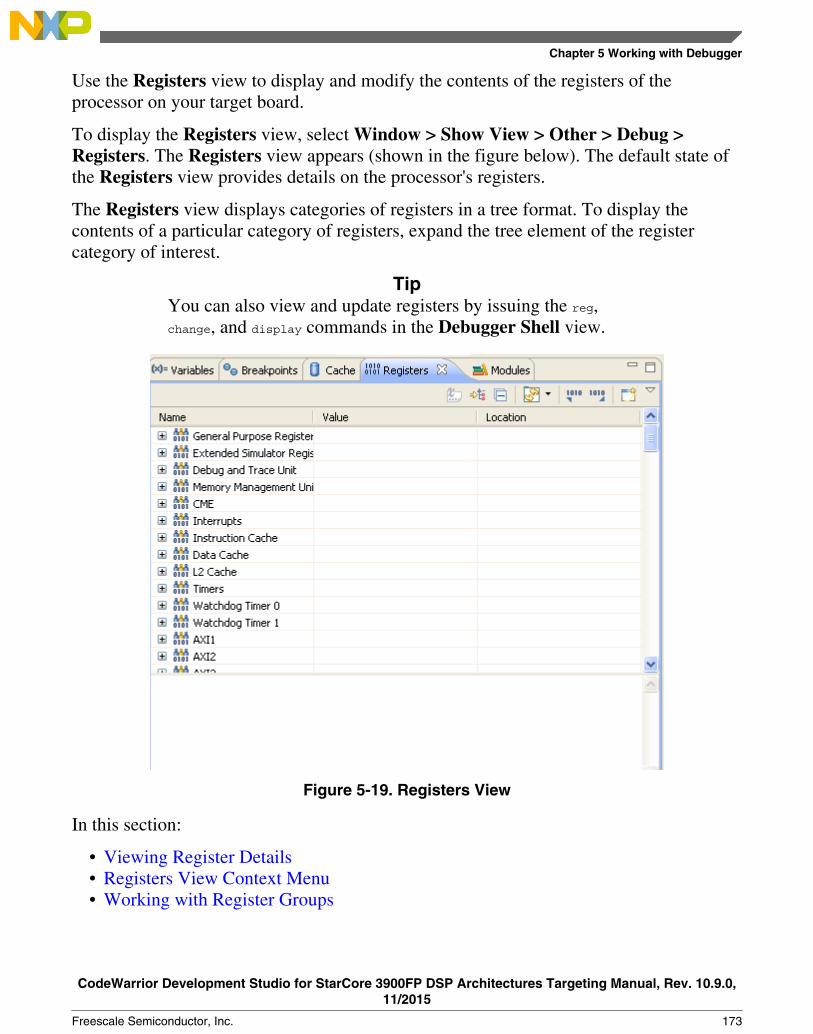
Use the Registers view to display and modify the contents of the registers of theprocessor on your target board.
To display the Registers view, select Window > Show View > Other > Debug >Registers. The Registers view appears (shown in the figure below). The default state ofthe Registers view provides details on the processor's registers.
The Registers view displays categories of registers in a tree format. To display thecontents of a particular category of registers, expand the tree element of the registercategory of interest.
TipYou can also view and update registers by issuing the reg,change, and display commands in the Debugger Shell view.
Figure 5-19. Registers View
In this section:
• Viewing Register Details• Registers View Context Menu• Working with Register Groups
Chapter 5 Working with Debugger
CodeWarrior Development Studio for StarCore 3900FP DSP Architectures Targeting Manual, Rev. 10.9.0,11/2015
Freescale Semiconductor, Inc. 173

5.6.1 Viewing Register Details
This section explains how to use the Registers view to show the details of a register.
To open the Registers view, you must first start a debugging session.
To see the registers and their descriptions, follow these steps:
1. In the Debug perspective, click the Registers view tab.
The Registers view appears, as shown in the figure below.
Figure 5-20. Registers View - Register Details2. Click the View Menu button (the inverted triangle) on the Registers view toolbar.3. Select Layout > Vertical or Layout > Horizontal to show register details.
NOTESelecting Layout > Registers View Only hides the registerdetails.
4. Expand a register group to see individual registers.
Working with Registers
CodeWarrior Development Studio for StarCore 3900FP DSP Architectures Targeting Manual, Rev. 10.9.0,11/2015
174 Freescale Semiconductor, Inc.

5. Select a specific register by clicking it.
The details of the selected register get displayed.
NOTEUse the Format list box to change the format of datadisplayed for the selected register.
6. Examine register details. For example,• Use the Bit Fields group to see a graphical representation of the selected
register's bit fields. You can use this graphical representation to select specificbits or bit fields.
• Use the Actions group to perform operations, such as update bit field values andformat the displayed register data.
• Use the Description group to see an explanation of the selected register, bitfield, or bit value.
TipTo enlarge the Registers view, click Maximize on theview's toolbar. After you finish looking at the registerdetails, click Restore on the view's toolbar to return theview to its previous size. Alternatively, right-click theRegisters tab and select Detached. The Registers viewbecomes a floating window that you can resize. After youfinish looking at the register details, right-click theRegisters tab of the floating window and select Detachedagain. You can rearrange the re-attached view by draggingits tab to a different collection of view tabs.
In this section:
• Bit Fields• Changing Bit Fields• Actions• Description
5.6.1.1 Bit Fields
Chapter 5 Working with Debugger
CodeWarrior Development Studio for StarCore 3900FP DSP Architectures Targeting Manual, Rev. 10.9.0,11/2015
Freescale Semiconductor, Inc. 175

The Bit Fields group of the Registers view (see the figure below) shows a graphicalrepresentation of the selected register's bit values. This graphical representation showshow the register organizes bits. You can use this representation to select and change theregister's bit values. Hover the cursor over each part of the graphical representation to seeadditional information.
Figure 5-21. Register Details - Bit Fields Group
TipYou can also view register details by issuing the reg commandin the Debugger Shell view.
A bit field is either a single bit or a collection of bits within a register. Each bit field has amnemonic name that identifies it. You can use the Field list box to view and select aparticular bit field of the selected register. The list box shows the mnemonic name andbit-value range of each bit field. In the Bit Fields graphical representation, a boxsurrounds each bit field. A red box surrounds the bit field shown in the Field list box.
After you use the Field list box to select a particular bit field, you see its current value inthe = text box. If you change the value shown in the text box, the Registers view showsthe new bit field value.
The minimum resolution of bit field descriptions is 2 bits. Consequently, register detailsare not available for single-bit overflow registers.
The maximum resolution of bit field descriptions is 32 bits.
5.6.1.2 Changing Bit Fields
To change a bit field in a register, you must first start a debugging session, and then openthe Registers view.
To change a bit field, perform these steps:
1. In the Registers view, view register details.2. Expand the register group that contains the bit field you want to change.
Register details appear in the Registers view.
Working with Registers
CodeWarrior Development Studio for StarCore 3900FP DSP Architectures Targeting Manual, Rev. 10.9.0,11/2015
176 Freescale Semiconductor, Inc.

3. From the expanded register group above the register details, select the name of theregister that contains the bit field that you want to change.
The Bit Fields group displays a graphical representation of the selected bit field. TheDescription group displays explanatory information about the selected bit field andparent register.
4. In the Bit Fields group, click the bit field that you want to change. Alternatively, usethe Field list box to specify the bit field that you want to change.
5. In the = text box, type the new value that you want to assign to the bit field.6. In the Action group, click Write.
The debugger updates the bit field value. The bit values in the Value column and theBit Fields group change to reflect your modification.
NOTEClick Revert to discard your changes and restore theoriginal bit field value.
5.6.1.3 Actions
Use the Actions group of the Registers view (see the figure below) to perform variousoperations on the selected register's bit field values.
Figure 5-22. Register View - Actions Group
The table below lists each item in the Actions group and explains the purpose of each.
Table 5-20. Actions Group Items
Item Description
Revert Discard your changes to the current bit field value and restore the original value. Thedebugger disables this button if you have not made any changes to the bit field value.
Write Save your changes to the current bit field value and write those changes into theregister's bit field. The debugger disables this button after writing the new bit fieldvalue, or if you have not made any changes to that value.
Reset Change each bit of the bit field value to its register-reset value. The register takes onthis value after a target-device reset occurs. To confirm the bit field change, click Write.To cancel the change, click Revert.
Table continues on the next page...
Chapter 5 Working with Debugger
CodeWarrior Development Studio for StarCore 3900FP DSP Architectures Targeting Manual, Rev. 10.9.0,11/2015
Freescale Semiconductor, Inc. 177

Table 5-20. Actions Group Items (continued)
Item Description
Summary Display Description group content in a pop-up window. Press the Esc key to close thepop-up window.
Format Specify the data format of the displayed bit field values.
5.6.1.4 Description
The Description group of the Registers view (see the figure below) shows explanatoryinformation for the selected register.
Figure 5-23. Register View - Description Group
The register information covers:
• Current value• Description• Bit field explanations and values
Some registers have multiple modes (meaning that the register's bits can have multiplemeanings, depending on the current mode). If the register you examine has multiplemodes, you must select the appropriate mode.
5.6.2 Registers View Context Menu
The Registers view context menu provides you various options for working withregisters.
To display the Registers view context menu, right-click a register in the Registers view.
The table below lists the options of the Registers view context menu.
Working with Registers
CodeWarrior Development Studio for StarCore 3900FP DSP Architectures Targeting Manual, Rev. 10.9.0,11/2015
178 Freescale Semiconductor, Inc.

Table 5-21. Registers View Context Menu Options
Option Description
Select All Selects the entire contents of the current register.
Copy Registers Copies to the system clipboard the contents of the selected register.
Enable Allows the debugger to access the selected register.
Disable Prevents the debugger from accessing the selected register.
View Memory Displays the corresponding memory for the selected register.
Format Use to specify the displayed data format for the selected register:• Natural: Default data format• Decimal: Decimal data format• Hexadecimal: Hexadecimal data format• Binary: Binary data format• Fractional: Fractional data formats, Q0-Q39
Cast to Type Opens a dialog box that you can use to cast the selected register value to a differentdata type.
Restore Original Type Reverts the selected register value to its default data type.
Find Opens a dialog box that you can use to select a particular register.
Change Value Opens a dialog box that you can use to change the current register value.
Show Details As Allows you to specify how the debugger displays the register's contents. The optionsare:
• Default Viewer: The register's contents are displayed as a hexadecimal value.• Register Details Panel: The register's values are display in a bit format, along
with a description of their purpose.
Add Register Group Opens a dialog box that you can use to create a new collection of registers to display inthe Registers view.
Restore Default Register Groups Resets the custom groups of registers created using the Add Register Group option,and restores the default groups provided by the debugger as they were whenCodeWarrior was installed. Note that if you select this option, all custom groupings ofregisters done by you are lost.
Add Watchpoint (C/C++) Opens the Add Watchpoint dialog box, proposing to set a watchpoint on anexpression representing the register. The debugger sets the watchpoint according tothe settings that you specify in the Add Watchpoint dialog box. The Breakpoints viewshows information about the newly set watchpoint. The Problems view shows errormessages when the debugger fails to set the watchpoint.
Watch Adds a new watch-expression entry to the Expressions view.
5.6.3 Working with Register Groups
This section describes different operations that can be performed on register groups.
You can perform the following operations on the register groups:
• Adding a Register Group• Editing a Register Group• Removing a Register Group
Chapter 5 Working with Debugger
CodeWarrior Development Studio for StarCore 3900FP DSP Architectures Targeting Manual, Rev. 10.9.0,11/2015
Freescale Semiconductor, Inc. 179

5.6.3.1 Adding a Register Group
The default display of the Registers view groups related registers into a tree structure.
You can add a custom group of registers to the default register tree structure.
To add a new register group, perform these steps:
1. Right-click in the Registers view.
A context menu appears.
2. Select Add Register Group from the context menu.
The Register Group dialog box appears, as shown in the figure below.
Figure 5-24. Register Group Dialog Box3. Enter in the Group Name text box a descriptive name for the new group.4. Select the checkbox next to each register you want to appear in the new group.
Working with Registers
CodeWarrior Development Studio for StarCore 3900FP DSP Architectures Targeting Manual, Rev. 10.9.0,11/2015
180 Freescale Semiconductor, Inc.

TipClick Select All to check all of the checkboxes. ClickDeselect All to clear all of the checkboxes.
5. Click OK.
The Register Group dialog box closes. The new group name appears in theRegisters view.
5.6.3.2 Editing a Register Group
In the Registers view, you can edit both the default register groups and the groups thatyou add.
To do so, use the following steps:
1. In the Registers view, right-click the name of the register group you want to edit.
A context menu appears.
2. Select Edit Register Group from the context menu.
The Register Group dialog box appears.
3. If you wish, enter in the Group Name text box a new name for the group.4. Check the checkbox next to each register you want to appear in the group.
TipClick Select All to check all of the checkboxes. ClickDeselect All to clear all of the checkboxes.
5. Click OK.
The Register Group dialog box closes. The new group name appears in theRegisters view.
5.6.3.3 Removing a Register Group
In the Registers view, you can remove register groups.
To remove a register group, follow these steps:
Chapter 5 Working with Debugger
CodeWarrior Development Studio for StarCore 3900FP DSP Architectures Targeting Manual, Rev. 10.9.0,11/2015
Freescale Semiconductor, Inc. 181

1. In the Registers view, right-click the name of register group that you wish toremove.
A context menu appears.
2. Select Remove Register Group from the context menu.
The selected register group disappears from the Registers view.
5.7 Viewing memory
This section explains how to view memory of a target processor.
Use the Memory view to examine the active memory rendering of a specified expressionor address. To display the Memory view, select Window > Show View > Other >Debug > Memory (shown in the figure below).
The Memory view supports the display of multiple memory spaces. The figure belowshows the Memory view with the Expression:baseaddr <name> tree active memoryrendering tab.
Figure 5-25. Memory View
In this section:• Adding Memory Monitor• Adding Memory Rendering• Removing Memory Rendering• Resetting to Base Address• Go to Address
Viewing memory
CodeWarrior Development Studio for StarCore 3900FP DSP Architectures Targeting Manual, Rev. 10.9.0,11/2015
182 Freescale Semiconductor, Inc.

5.7.1 Adding Memory Monitor
This section describes how to add memory monitor in the Memory view.
To display the supported memory spaces for a target in the Memory view, perform thefollowing steps:
You can add multiple memory monitors to the Memory view. To add a new memorymonitor, follow these steps:
1. Start a debugging session.2. Open the Memory view.3. Click the plus sign (+) icon on the Monitors pane toolbar. Alternatively, right-click
in the Monitors pane and select Add Memory Monitor from the context menu.
The Monitor Memory dialog box appears, as shown in the figure below.
NOTEThe Memory space option appears only when thedebugger associated with the active debugging contextsupports memory spaces, and the currently debuggedprocess has multiple memory spaces.
Figure 5-26. Monitor Memory Dialog Box4. Specify information about the memory monitor:
• To enter a memory space and literal address, simply enter an address.• To enter an expression, type in the expression. If you enter a literal address as
the expression, use the prefix 0x to indicate hexadecimal notation, or use noprefix to indicate decimal notation. You can use the drop-down list to select apreviously specified expression.
NOTEIf you do not select a memory space and the expressiondoes not contain a memory space then the memory
Chapter 5 Working with Debugger
CodeWarrior Development Studio for StarCore 3900FP DSP Architectures Targeting Manual, Rev. 10.9.0,11/2015
Freescale Semiconductor, Inc. 183

space is set to default data memory space that isspecific for each architecture
5. Select the Memory space checkbox to translate the memory address or theexpression to another memory space.
The Memory space drop-down list is enabled.
6. Select one of the following values from the Memory space drop-down list:
Figure 5-27. Monitor Memory Dialog Box - Memory space Options
• Physical: Indicates that the specified address or expression refers to physicalmemory space.
• Data: Indicates that the specified address or expression refers to data memoryspace.
• Program: Indicates that the specified address or expression refers to programmemory space.
• Physical cache - inhibited: Similar with the Physical memory space, but nocached information will be used when the data is displayed.
• SAP: The memory is accessible while the system is running. The target must notbe running for the above listed memory spaces. While using this memory space,other memory spaces will not be available.
NOTEThis memory space is available only for hardwaretargets.
7. Click OK.
After evaluating the expression, an address and a memory space are generated. Thedebugger is responsible for converting the address and the memory space into a newaddress and other memory space that user selected.
The debugger uses the following rules to perform the address and memory spaceconversion:
Viewing memory
CodeWarrior Development Studio for StarCore 3900FP DSP Architectures Targeting Manual, Rev. 10.9.0,11/2015
184 Freescale Semiconductor, Inc.

• If memory space is NA or it is not compatible with selected memory space, thenthe new expression address has the same value as evaluated address. Forexample, Data:0x100 should be converted to Program:0x100, because the Data andProgram memory spaces are not compatible.
• If memory space is compatible with selected memory space, than the newexpression address is computed based on the MMU information. For example,Data:0x100 should be converted to Physical:0x2100 based on MMU configuration(data:0x0 --> physical:0x2000).
NOTEIn both scenarios, the new address and new memory spacefor expression will be displayed in memory rendering labeland title along with the original expression.
The memory monitor is added to the Monitors panel and the default rendering isdisplayed in the Renderings panel.
5.7.2 Adding Memory Rendering
You can use the Renderings tab page of the Memory view to examine the memorycontent, starting at any valid address. The information displayed in this page is read-onlyand cannot be used to modify the memory content.
To add a new memory rendering, follow these steps:
1. Start a debugging session.2. Open the Memory view.3. In the Monitors pane, select the memory monitor for which you want to add a
memory rendering.
NOTETo create a memory monitor, right-click a blank area in theMonitors pane and select Add Memory Monitor.Alternatively, click the plus sign (+) icon in the Monitorspane toolbar.
4. Click the New Renderings tab in the Memory view.
The New Renderings tab page appears, as shown in the figure below.
Chapter 5 Working with Debugger
CodeWarrior Development Studio for StarCore 3900FP DSP Architectures Targeting Manual, Rev. 10.9.0,11/2015
Freescale Semiconductor, Inc. 185

Figure 5-28. New Renderings Tab Page5. Select a rendering type from the Select rendering(s) to create list.6. Click Add Rendering(s).
The selected memory rendering type appears in the Memory view.
5.7.3 Removing Memory Rendering
To remove a memory rendering from the Memory view, follow these steps:
1. Open the Memory view.2. In the Renderings tab page, select the tab that corresponds to the memory rendering
that you want to remove.3. Select Remove Rendering from the context menu.
The memory rendering is removed from the Memory view.
5.7.4 Resetting to Base Address
To reset the memory rendering and display the base address of the rendering, followthese steps:
1. Open the Memory view.2. In the Renderings tab page, select the tab that corresponds to the disassembly
rendering that you want to reset to the base address.3. Select Reset to Base from the context menu.
Viewing memory
CodeWarrior Development Studio for StarCore 3900FP DSP Architectures Targeting Manual, Rev. 10.9.0,11/2015
186 Freescale Semiconductor, Inc.

The disassembly rendering scrolls to the line that contains the base address of thedisplayed rendering.
5.7.5 Go to Address
The memory view provides graphical controls to display memory at a specific address.To go to a specific address, follow these steps:
1. Open the Memory view.2. In the Renderings tab page, select the tab that corresponds to the disassembly
rendering for which you want to display a specific address.3. Select Go to Address from the context menu.
A group of controls appears on the Renderings tab page, as shown in the figurebelow.
Figure 5-29. Disassembly Rendering - Go to Address4. In the blank text box, enter the address that you want to display.
NOTESelect the Input as Hex checkbox only if you enter theaddress in hexadecimal notation.
5. Click OK to have the Disassembly rendering scroll to the specified address.Alternatively, click Cancel to abort the operation and hide the group of controls.
5.8 Viewing Cache
This section provides detailed information on working with caches.
Chapter 5 Working with Debugger
CodeWarrior Development Studio for StarCore 3900FP DSP Architectures Targeting Manual, Rev. 10.9.0,11/2015
Freescale Semiconductor, Inc. 187

The CodeWarrior debugger allows you to view and modify the instruction cache and datacache of the target system during a debug session. The CodeWarrior for StarCore currentrelease supports the cache viewer for L1 instruction, L1 data, L2 and L3 both instructionand data cache.
NOTEProjects created for ISS targets do not support cache.
In this section:
• Cache View• Cache View Toolbar Menu
5.8.1 Cache View
This section describes how to use Cache view.
Use the Cache view to examine L1 cache (such as instruction cache or data cache). Also,you can use the viewer to display L2 and L3 cache for targets that support it.
Use the Cache view to examine L1 cache (such as instruction cache or data cache). Youcan also use the viewer to display L2 and L3 cache for the supported targets. To open theCache view, use the following steps:
1. Start a debugging session.2. From the CodeWarrior IDE menu bar, select Window > Show View > Other.
The Show View dialog box appears.
3. Expand the Debug group.4. Select Cache.5. Click OK.
The Cache view appears, as shown in the figure below.
Viewing Cache
CodeWarrior Development Studio for StarCore 3900FP DSP Architectures Targeting Manual, Rev. 10.9.0,11/2015
188 Freescale Semiconductor, Inc.
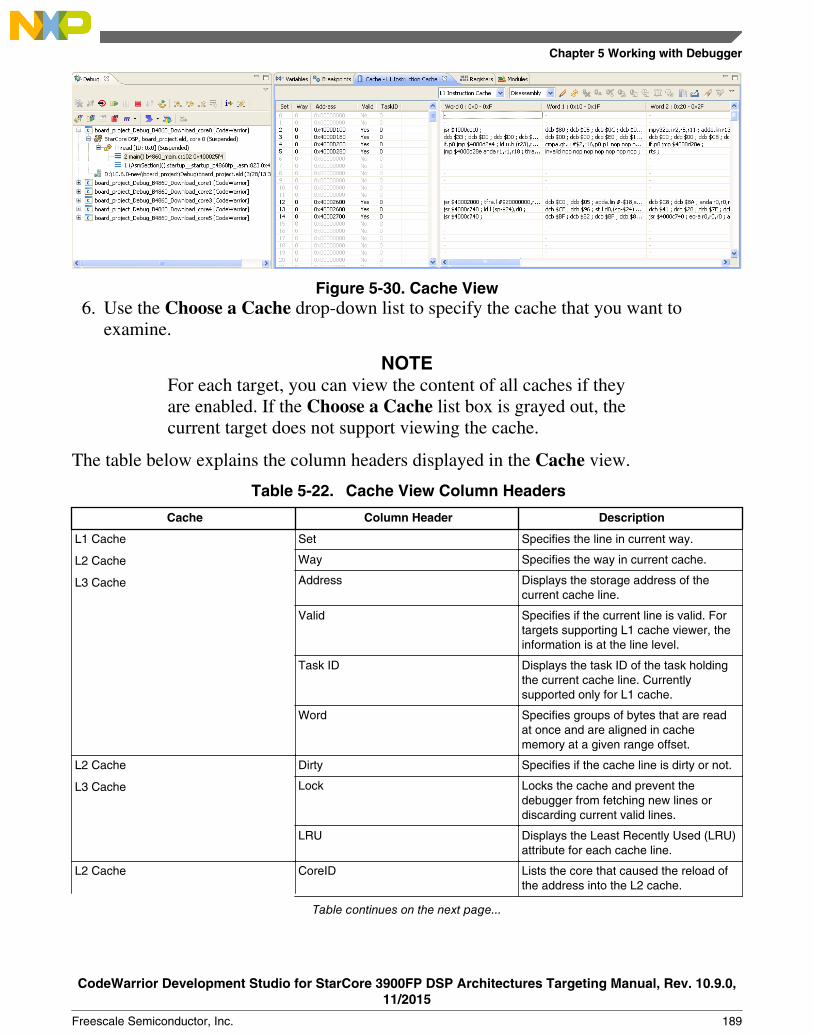
Figure 5-30. Cache View6. Use the Choose a Cache drop-down list to specify the cache that you want to
examine.
NOTEFor each target, you can view the content of all caches if theyare enabled. If the Choose a Cache list box is grayed out, thecurrent target does not support viewing the cache.
The table below explains the column headers displayed in the Cache view.
Table 5-22. Cache View Column Headers
Cache Column Header Description
L1 Cache
L2 Cache
L3 Cache
Set Specifies the line in current way.
Way Specifies the way in current cache.
Address Displays the storage address of thecurrent cache line.
Valid Specifies if the current line is valid. Fortargets supporting L1 cache viewer, theinformation is at the line level.
Task ID Displays the task ID of the task holdingthe current cache line. Currentlysupported only for L1 cache.
Word Specifies groups of bytes that are readat once and are aligned in cachememory at a given range offset.
L2 Cache
L3 Cache
Dirty Specifies if the cache line is dirty or not.
Lock Locks the cache and prevent thedebugger from fetching new lines ordiscarding current valid lines.
LRU Displays the Least Recently Used (LRU)attribute for each cache line.
L2 Cache CoreID Lists the core that caused the reload ofthe address into the L2 cache.
Table continues on the next page...
Chapter 5 Working with Debugger
CodeWarrior Development Studio for StarCore 3900FP DSP Architectures Targeting Manual, Rev. 10.9.0,11/2015
Freescale Semiconductor, Inc. 189
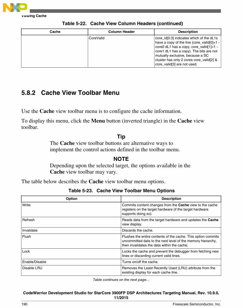
Table 5-22. Cache View Column Headers (continued)
Cache Column Header Description
CoreValid core_id[0:3] indicates which of the dL1shave a copy of the line (core_valid[0]=1 -core0 dL1 has a copy, core_valid[1]=1 -core1 dL1 has a copy). The bits are notmutually exclusive, because a SCcluster has only 2 cores core_valid[2] &core_valid[3] are not used.
5.8.2 Cache View Toolbar Menu
Use the Cache view toolbar menu is to configure the cache information.
To display this menu, click the Menu button (inverted triangle) in the Cache viewtoolbar.
TipThe Cache view toolbar buttons are alternative ways toimplement the control actions defined in the toolbar menu.
NOTEDepending upon the selected target, the options available in theCache view toolbar may vary.
The table below describes the Cache view toolbar menu options.
Table 5-23. Cache View Toolbar Menu Options
Option Description
Write Commits content changes from the Cache view to the cacheregisters on the target hardware (if the target hardwaresupports doing so).
Refresh Reads data from the target hardware and updates the Cacheview display.
Invalidate Discards the cache.
Flush Flushes the entire contents of the cache. This option commitsuncommitted data to the next level of the memory hierarchy,then invalidates the data within the cache.
Lock Locks the cache and prevent the debugger from fetching newlines or discarding current valid lines.
Enable/Disable Turns on/off the cache.
Disable LRU Removes the Least Recently Used (LRU) attribute from theexisting display for each cache line.
Table continues on the next page...
Viewing Cache
CodeWarrior Development Studio for StarCore 3900FP DSP Architectures Targeting Manual, Rev. 10.9.0,11/2015
190 Freescale Semiconductor, Inc.

Table 5-23. Cache View Toolbar Menu Options (continued)
Option Description
Enable/Disable Parity Turns on/off the line data parity checksum calculation.
Inverse LRU Displays the inverse of the Least Recently Used attribute foreach cache line.
Copy Cache Copies the cache contents to the system clipboard.
Export Cache Exports the cache contents to a file.
Search Finds an occurrence of a string in the cache lines.
Search Again Finds the next occurrence of a string in the cache lines.
Preserve Sorting Preserves sorting of the cache when the cache data isupdated and the cache is refreshing. This option is disabledby default. If enabled, every operation that triggers cacherefresh (such as step, run to breakpoint) will have to wait forcache data loading and sorting.
View Memory Allows you to view the corresponding memory for the selectedcache lines.
Lock Line Locks the selected cache lines.
Invalidate Line Invalidates the selected cache lines.
Flush Line Flushes the entire contents of the selected cache lines.
Synchronize Line Synchronizes selected cache data with memory data.
Lock Way Locks the cache ways specified with the Lock Ways menuoption. Locking a cache way means that the data contained inthat way must not change. If the cache needs to discard aline, it will not discard locked lines (such as lines explicitlylocked, or lines belonging to locked ways).
Unlock Way Unlocks the cache ways specified with the Lock Ways menuoption.
Lock Ways Specifies the cache ways on which the Lock Way andUnlock Way menu options operate.
5.9 Changing Program Counter Value
This section explains how to change the program counter value in the CodeWarrior IDEto make the debugger execute a specific line of code.
To change the program counter value, follow these steps:
1. Start a debugging session.2. In the Editor view, place the cursor on the line that you want the debugger to execute
next.3. Right-click in the Editor view.
A context menu appears.
Chapter 5 Working with Debugger
CodeWarrior Development Studio for StarCore 3900FP DSP Architectures Targeting Manual, Rev. 10.9.0,11/2015
Freescale Semiconductor, Inc. 191
4. From the context menu, select Move To Line.
The CodeWarrior IDE modifies the program counter according to the specified location.The Editor view shows the new location.
5.10 Hard resetting
Use the reset hard command in the Debugger Shell view to send a hard reset signal to thetarget processor.
NOTEThe Hard Reset command is enabled only if the debughardware you are using supports it.
Tip
You can also perform a hard reset by clicking Reset ( ) onthe Debug perspective toolbar.
5.11 Per Core Reset
This section describes how to enable per core reset.
To enable, follow the steps listed below:
1. Select Run > Debug Configurations from the IDE menu bar.
The Debug Configurations dialog box appears.
2. Expand the CodeWarrior tree control, and select the desired target core.3. In the right panel, click Edit from the Target settings group.
The Properties for <target> dialog box appears.
4. Click Edit.
The Properties for <target> Target dialog box with Hardware or SimulatorTarget page in the right panel appears, as the Figure 5-31 shows.
Hard resetting
CodeWarrior Development Studio for StarCore 3900FP DSP Architectures Targeting Manual, Rev. 10.9.0,11/2015
192 Freescale Semiconductor, Inc.

Figure 5-31. Properties for <target> Target Dialog Box5. Select the checkbox in the Core reset column, corresponding to the desired target in
the Target column (Figure 5-31).6. Click OK.
The Properties for <target> Target dialog box closes and the core reset is enabledfor the selected target.
NOTEPer-core reset affects only the debugged core if thecorresponding Core reset option is selected.
NOTECore reset will be ignored when the current core is the firstdebugged core from the processor and Execute target reset orthe Processor reset checkboxes are checked.
5.12 Setting Stack Depth
This section describes how to control the depth of the call stack displayed by thedebugger.
Chapter 5 Working with Debugger
CodeWarrior Development Studio for StarCore 3900FP DSP Architectures Targeting Manual, Rev. 10.9.0,11/2015
Freescale Semiconductor, Inc. 193

Select Window > Preferences > C/C++ > Debug > Maximum stack crawl depthoption to set the depth of the stack to read and display. Showing all levels of calls whenyou are examining function calls several levels deep can sometimes make steppingthrough code more time consuming. Therefore, you can use this menu option to reducethe depth of calls that the debugger displays.
5.13 Import a CodeWarrior Executable file Wizard
The Import a CodeWarrior Executable file wizard helps you to import a CodeWarriorexecutable file and create a new project.
To use the Import a CodeWarrior Executable file wizard, perform these steps:
1. From the CodeWarrior IDE menu bar, select File > Import.
The Import wizard launches and the Select page appears, as shown in the figurebelow.
Figure 5-32. Import Wizard - Selecting CodeWarrior Executable Importer2. Expand the CodeWarrior group.3. Select the CodeWarrior Executable Importer to import a StarCore .eld file.4. Click Next.
Import a CodeWarrior Executable file Wizard
CodeWarrior Development Studio for StarCore 3900FP DSP Architectures Targeting Manual, Rev. 10.9.0,11/2015
194 Freescale Semiconductor, Inc.

The wizard name changes to Import a CodeWarrior Executable file and theImport a CodeWarrior Executable file page appears.
The following sections describe the various pages that the wizard displays as it assistsyou in importing an executable (.eld) file:
• Import a CodeWarrior Executable file Page• Import C/C++/Assembler Executable Files Page• Processor Page• Debug Target Settings Page
5.13.1 Import a CodeWarrior Executable file Page
Use the Import a CodeWarrior Executable file page to specify the name and locationfor your project.
Figure 5-33. StarCore Executable - Import a CodeWarrior Executable File Page
The table below describes the options available on this page.
Chapter 5 Working with Debugger
CodeWarrior Development Studio for StarCore 3900FP DSP Architectures Targeting Manual, Rev. 10.9.0,11/2015
Freescale Semiconductor, Inc. 195

Table 5-24. Import a CodeWarrior Executable file page settings
Option Description
Project name Specify the name of the project. The specified name identifies the project created fordebugging (but not building) the executable file.
Use default location If you select this option, the project files required to build the program are stored in thecurrent workspace directory of the workbench. If you clear this option, the project filesare stored in the directory that you specify in the Location option.
Location Specifies the directory that contains the project files. Use the Browse button to navigateto the desired directory. This option is only available when the Use default locationoption is cleared.
5.13.2 Import C/C++/Assembler Executable Files Page
Use the Import C/C++/Assembler Executable Files page to select an executable file ora folder to search for C/C++/assembler executable files.
Figure 5-34. StarCore Executable - Import C/C++/Assembler Executable Files Page
The table below explains the options available on the page.
Import a CodeWarrior Executable file Wizard
CodeWarrior Development Studio for StarCore 3900FP DSP Architectures Targeting Manual, Rev. 10.9.0,11/2015
196 Freescale Semiconductor, Inc.

Table 5-25. Import C/C++/Assembler Executable Files page settings
Option Description
File to import Specifies the C/C++/assembler executable file. Click Browseto choose an executable file.
Copy the selected file to current project folder Select this option to copy the executable file in the projectfolder.
5.13.3 Processor Page
Use the Processor page to specify the processor family for the imported executable file.
Figure 5-35. StarCore Executable - Processor Page
The table below describes the options available on the page.
Table 5-26. Processor page settings
Option Description
Processor Expand the processor family and select the appropriate target processor for theexecution of the specified executable file.
Tip: You can also type the processor name in the text box.
Chapter 5 Working with Debugger
CodeWarrior Development Studio for StarCore 3900FP DSP Architectures Targeting Manual, Rev. 10.9.0,11/2015
Freescale Semiconductor, Inc. 197

5.13.4 Debug Target Settings Page
Use the Debug Target Settings page to specify debugger connection type, board type,launch configuration type, and connection type for your project.
This page also allows you to configure connection settings for your project.
Figure 5-36. StarCore Executable - Debug Target Settings Page
The table below describes the options available on the page.
Table 5-27. Debug Target Settings page settings
Option Description
Debugger Connection Types Specifies what target the program executes on.• Hardware: Select to execute the program on the hardware available for the
product.• Simulator: Select to execute the program on a software simulator.• Emulator: Select to execute the program on a hardware emulator.
Board Specifies the hardware (board) supported by the selected processor.
Launch Specifies the launch configurations and corresponding connection configurations,supported by the selected processor.
Connection Specifies the connection configuration used by the project.• Default: Select to create a new connection with default configuration.• Create New: Select to create a new connection configuration manually.• Edit Remote Systems: Select to edit existing remote systems.
Table continues on the next page...
Import a CodeWarrior Executable file Wizard
CodeWarrior Development Studio for StarCore 3900FP DSP Architectures Targeting Manual, Rev. 10.9.0,11/2015
198 Freescale Semiconductor, Inc.

Table 5-27. Debug Target Settings page settings (continued)
Option Description
Connection Type Specifies the interface to communicate with the hardware.
TAP address Enter the IP address of the selected TAP device.
5.14 Debugging Externally Built Executable Files
You can use the Import a CodeWarrior Executable file wizard to debug an externallybuilt executable file, that is, an executable (.eld) file that has no associated CodeWarriorproject.
For example, you can debug a .eld file that was generated using a different IDE. Theprocess of debugging an externally built executable file can be divided into the followingtasks:
• Import an Executable File• Edit the Launch Configuration• Specify the Source Lookup Path• Debug Executable File
5.14.1 Import an Executable File
First of all, you need to import the executable file that you want the CodeWarrior IDE todebug.
The IDE imports the executable file into a new project.
To import an externally built executable file, follow these steps:
1. From the CodeWarrior IDE menu bar, select File > Import.
The Import wizard appears.
2. Expand the CodeWarrior group.3. Select CodeWarrior Executable Importer to import a StarCore .eld file.4. Click Next.
The wizard name changes to Import a CodeWarrior Executable file and theImport a CodeWarrior Executable file page appears.
Chapter 5 Working with Debugger
CodeWarrior Development Studio for StarCore 3900FP DSP Architectures Targeting Manual, Rev. 10.9.0,11/2015
Freescale Semiconductor, Inc. 199

5. In the Project name text box, enter the name of the project. This name identifies theproject that the IDE creates for debugging (but not building) the executable file.
6. Clear the Use default location checkbox and click Browse to specify a differentlocation for the new project. By default, the Use default location checkbox isselected.
7. Click Next.
The Import C/C++/Assembler Executable Files page appears.
8. Click Browse.
The Select file dialog box appears. Use the dialog box to navigate to the executablefile that you want to debug.
9. Select the required file and click Open.
The Select file dialog box closes. The path to the executable file appears in the Fileto import text box.
10. Check the Copy the selected file to current project folder checkbox to copy theexecutable file in the current workspace.
11. Click Next.
The Processor page appears.
12. Select the appropriate target processor from the StarCore Family list.
13. Click Next.
The Debug Target Settings page appears.
14. Select a debugger connection type for the execution of the specified executable file:• Simulator: If you select this option, the program executes on a software
simulator.• Hardware: If you select this option, the program executes on the hardware
available for the product.15. Select the connection type you want to use, from the Debugger Connection Types
group.16. Select the board, you plan to use, from the Board drop-down list.17. Select the launch configurations, that you want to include in your project and the
corresponding connection configuration.
NOTEFor more information on remote systems, see CodeWarriorDevelopment Studio Common Features Guide.
18. Click Finish.
Debugging Externally Built Executable Files
CodeWarrior Development Studio for StarCore 3900FP DSP Architectures Targeting Manual, Rev. 10.9.0,11/2015
200 Freescale Semiconductor, Inc.

The CodeWarrior Executable Importer wizard creates a new project according toyour specifications. You can access the project from the CodeWarrior Projectsview in the IDE.
5.14.2 Edit the Launch Configuration
Using the tabs of the Debug Configurations dialog box, you can change the launchconfiguration settings that you specified while importing the .eld file.
To edit the launch configuration for your executable file, follow these steps:
1. Click the Debugger tab of the Debug Configurations dialog box.
The corresponding page appears.
2. Configure the debugger options as appropriate for your executable file.
For example, specify the appropriate target processor, any initialization files, andconnection protocol.
5.14.3 Specify the Source Lookup Path
Source lookup path is specified in terms of the compilation path and the local file systempath.
The CodeWarrior debugger uses both these paths to debug the executable file.
The compilation path is the path to the original project that built the executable file. If theoriginal project is from an IDE on a different computer, you need to specify thecompilation path in terms of the file system on that computer.
The local file system path is the path to the project that the CodeWarrior IDE creates todebug the executable file.
The CodeWarrior IDE supports automatic as well as manual path mapping.
In this section:
• Automatic Path Mapping• Manual Path Mapping
Chapter 5 Working with Debugger
CodeWarrior Development Studio for StarCore 3900FP DSP Architectures Targeting Manual, Rev. 10.9.0,11/2015
Freescale Semiconductor, Inc. 201
5.14.3.1 Automatic Path Mapping
This section describes how to set automatic path mapping for your project.
The Automatic Path Mapping feature focuses on reducing as much as possible themanual steps required by the user to set up the path mapping settings to support sourcelevel debugging.
For automatic path mapping, use these steps:
1. In the CodeWarrior Projects view, expand Binaries folder.2. Right-click the *.eld file and select Properties from the context menu that appears.
The Properties for <project>.eld dialog box appears.
3. Select Path Mappings from the list.
The Path Mappings page appears. The Path Mapping Configuration page displaysevery path mapping settings for the launch configurations associated with a project.You can edit either a single set of settings for all launch configurations associatedwith a project or the settings for a given launch configuration by selecting theappropriate value from the launch configuration combo box.
Under each path mapping, the table displays a list of source files that exist in thebinary executable that share the same source mapping prefix. In the Local Pathcolumn, a green ( ) is displayed if the file exists after being mapped by thedestination path or a red ( ) if it does not. Also, the local path itself is displayed inred if it does not exist on the local file system.
A default folder named Files Not Mapped is created if the user explicitly removesexisting mappings. All unmapped files that are not found on the file system areautomatically shown under this folder.
Debugging Externally Built Executable Files
CodeWarrior Development Studio for StarCore 3900FP DSP Architectures Targeting Manual, Rev. 10.9.0,11/2015
202 Freescale Semiconductor, Inc.
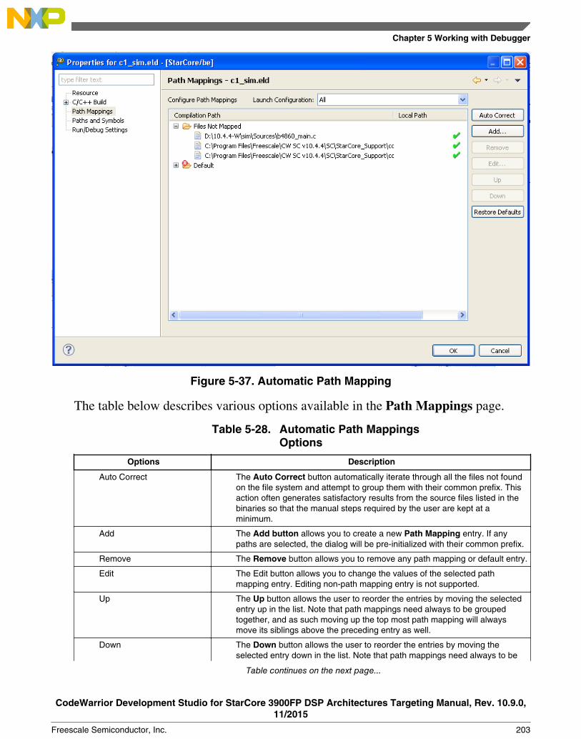
Figure 5-37. Automatic Path Mapping
The table below describes various options available in the Path Mappings page.
Table 5-28. Automatic Path MappingsOptions
Options Description
Auto Correct The Auto Correct button automatically iterate through all the files not foundon the file system and attempt to group them with their common prefix. Thisaction often generates satisfactory results from the source files listed in thebinaries so that the manual steps required by the user are kept at aminimum.
Add The Add button allows you to create a new Path Mapping entry. If anypaths are selected, the dialog will be pre-initialized with their common prefix.
Remove The Remove button allows you to remove any path mapping or default entry.
Edit The Edit button allows you to change the values of the selected pathmapping entry. Editing non-path mapping entry is not supported.
Up The Up button allows the user to reorder the entries by moving the selectedentry up in the list. Note that path mappings need always to be groupedtogether, and as such moving up the top most path mapping will alwaysmove its siblings above the preceding entry as well.
Down The Down button allows the user to reorder the entries by moving theselected entry down in the list. Note that path mappings need always to be
Table continues on the next page...
Chapter 5 Working with Debugger
CodeWarrior Development Studio for StarCore 3900FP DSP Architectures Targeting Manual, Rev. 10.9.0,11/2015
Freescale Semiconductor, Inc. 203

Table 5-28. Automatic Path Mappings Options(continued)
Options Description
grouped together, and as such moving down the bottom most path mappingwill always move its siblings below the following entry as well.
Restore Defaults The Restore Defaults button resets the launch configuration path mappingssettings to their previous values, including the library path mappingautomatically generated by the APM plug-in.
NOTEIf you create a new path mappings manually from thesource lookup path, the source files are automaticallyresorted to their most likely path mapping parent.
4. Click OK.
The Path Mappings dialog box closes.
5.14.3.2 Manual Path Mapping
This section describes how to set path mapping manually in your project.
To manually specify the source lookup path for the newly imported executable file, usethese steps:
1. Click the Source tab of the Debug Configurations dialog box.
The corresponding page appears, as shown in the figure below.
Debugging Externally Built Executable Files
CodeWarrior Development Studio for StarCore 3900FP DSP Architectures Targeting Manual, Rev. 10.9.0,11/2015
204 Freescale Semiconductor, Inc.

Figure 5-38. Debug Configurations - Source Page
Like Source tab, you can also use Edit Source Lookup Path dialog box to manuallyspecify the source lookup path. To open the Edit Source Lookup Path dialog box,right-click in the Debug view and select Edit Source Lookup.
Chapter 5 Working with Debugger
CodeWarrior Development Studio for StarCore 3900FP DSP Architectures Targeting Manual, Rev. 10.9.0,11/2015
Freescale Semiconductor, Inc. 205

Figure 5-39. Edit Source Lookup Path Dialog Box2. Click Add.
The Add Source dialog box appears.
3. Select Path Mapping (see the figure below).
Debugging Externally Built Executable Files
CodeWarrior Development Studio for StarCore 3900FP DSP Architectures Targeting Manual, Rev. 10.9.0,11/2015
206 Freescale Semiconductor, Inc.

Figure 5-40. Add Source Dialog Box4. Click OK.
The Path Mappings dialog box appears (shown in the figure below).
5. In the Name text box, enter the name of the new path mapping.
The name you enter also appears in the Source Lookup Path list of the Source page.
Chapter 5 Working with Debugger
CodeWarrior Development Studio for StarCore 3900FP DSP Architectures Targeting Manual, Rev. 10.9.0,11/2015
Freescale Semiconductor, Inc. 207

Figure 5-41. Path Mappings Dialog Box6. Click Add.7. In the Compilation path text box, enter the path to the parent project of the
executable file, relative to the computer that generated the file.
For example, the computer on which you debug the executable file is not the samecomputer that generated that executable file. On the computer that generated theexecutable file, the path to the parent project is D:\workspace\originalproject. Enter thispath in the Compilation path text box.
TipYou can use the IDE to discover the path to the parentproject of the executable file, relative to the computer thatgenerated the file. In the C/C++ Projects view of the C/C++ perspective, expand the project that contains theexecutable file that you want to debug. Next, expand thegroup that has the name of the executable file itself. A listof paths appears, relative to the computer that generated thefile. Search this list for the names of source files used tobuild the executable file. The path to the parent project ofone of these source files is the path you should enter in theCompilation path text box.
Debugging Externally Built Executable Files
CodeWarrior Development Studio for StarCore 3900FP DSP Architectures Targeting Manual, Rev. 10.9.0,11/2015
208 Freescale Semiconductor, Inc.

8. In the Local file system path text box, enter the path to the parent project of theexecutable file, relative to your computer. Alternatively, click the Browse button tospecify the parent project.
Suppose the computer on which you debug the executable file is not the samecomputer that generated that executable file. On your current computer, the path tothe parent project of the executable file is C:\projects\thisproject. Enter this path inthe Local file system path text box.
9. Click OK.
The Path Mappings dialog box closes. The mapping information now appears underthe path mapping shown in the Source Lookup Path list of the Source page.
10. If needed, change the order in which the IDE searches the paths.
The IDE searches the paths in the order shown in the Source Lookup Path list,stopping at the first match. To change this order, select a path, then click the Up orDown button to change its position in the list.
11. Click Apply.
The IDE saves your changes.
5.14.4 Debug Executable File
You can use the CodeWarrior debugger to debug the externally built executable file.
To debug the executable file:
1. Select the project in the CodeWarrior Projects view.2. Click the Debug button from the IDE toolbar.
The IDE switches to Debug perspective listing the debugging output.
Chapter 5 Working with Debugger
CodeWarrior Development Studio for StarCore 3900FP DSP Architectures Targeting Manual, Rev. 10.9.0,11/2015
Freescale Semiconductor, Inc. 209

Debugging Externally Built Executable Files
CodeWarrior Development Studio for StarCore 3900FP DSP Architectures Targeting Manual, Rev. 10.9.0,11/2015
210 Freescale Semiconductor, Inc.
Chapter 6Target Initialization File
This chapter explains the target initialization file and lists an example.
The initialization file is a text file that contains commands that tell the debugger how toinitialize your hardware after reset but before downloading code. Use the initializationfile commands to write values to various registers, core registers, and memory locations.
To use an initialization file, you must check the Use Initialization File box and specifythe name of your initialization file in the Debugger settings panel.
The target initialization files for the StarCore 3900FP DSP targets are available at:
Windows
<CWInstallDir>\SC\StarCore_Support\Initialization_Files\RegisterConfigFiles\
For example, B4860_QDS_Init.tcl.
NOTEYou can customize the contents of B4860_QDS_Init.tcl if needed.
For details about commands, see Debugger Shell Command List .
CodeWarrior Development Studio for StarCore 3900FP DSP Architectures Targeting Manual, Rev. 10.9.0,11/2015
Freescale Semiconductor, Inc. 211

CodeWarrior Development Studio for StarCore 3900FP DSP Architectures Targeting Manual, Rev. 10.9.0,11/2015
212 Freescale Semiconductor, Inc.

Chapter 7Memory Configuration File
This chapter explains the memory configuration file, and lists an example.
The memory configuration file is a text file that contains commands that tell the compilerhow to initialize the hardware memory after reset, but before downloading code. Use thememory configuration files to write values to various memory locations.
The memory configuration files are available at the following location:
<CWinstallDir>\SC\StarCore_Support\Initialization_Files\MemoryConfigFiles
The syntax for memory configuration is defined in each of memory configuration filesavailable with the CodeWarrior layout. For example, you can refer to theB4860_Memory_Example.mem file at the mentioned location.
To specify memory configuration file for a target:
1. Open the Debug Configurations dialog box.2. Click the Edit button in the Target settings area.
The Properties for <connection> dialog box appears.
3. Click the Edit button next to the Target field.
The Properties for <project> Target dialog box appears.
4. Select the target for which you want to specify the memory file from the Target typedrop-down list.
5. Click the Memory tab.6. Check the Memory configuration checkbox for the target or core(s) for which you
want to specify the memory file.7. Click the corresponding Memory configuration file column.8. Locate and specify a valid memory configuration file using the Memory
Configuration File dialog box that appears on clicking the Ellipse button in theMemory configuration file column.
CodeWarrior Development Studio for StarCore 3900FP DSP Architectures Targeting Manual, Rev. 10.9.0,11/2015
Freescale Semiconductor, Inc. 213
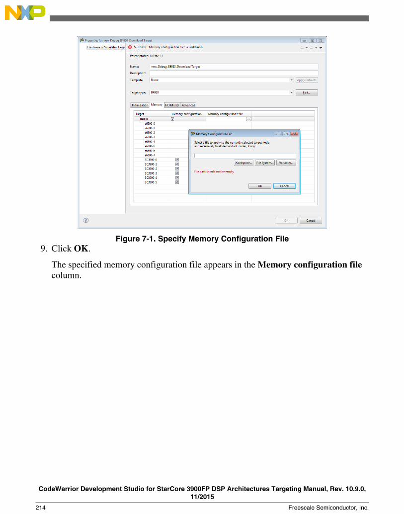
Figure 7-1. Specify Memory Configuration File9. Click OK.
The specified memory configuration file appears in the Memory configuration filecolumn.
CodeWarrior Development Studio for StarCore 3900FP DSP Architectures Targeting Manual, Rev. 10.9.0,11/2015
214 Freescale Semiconductor, Inc.

Chapter 8CodeWarrior Command-Line Debugging
CodeWarrior supports a command-line interface to some of its features including thedebugger.
You can use the command-line interface together with various scripting engines, such asthe Microsoft® Visual Basic® script engine, the Java™ script engine, TCL, Python, andPerl. You can even issue a command that saves the command-line activity to a log file.
This chapter explains:
• Working with Debugger Shell• Tcl Support• Command-Line Debugging Tasks• Debugger Shell Command List
8.1 Working with Debugger Shell
You use the Debugger Shell view to issue command lines to the IDE.
For example, you enter the command debug in this window to start a debugging session.The window lists the standard output and standard error streams of command-lineactivity.
CodeWarrior Development Studio for StarCore 3900FP DSP Architectures Targeting Manual, Rev. 10.9.0,11/2015
Freescale Semiconductor, Inc. 215
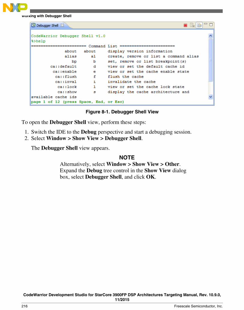
Figure 8-1. Debugger Shell View
To open the Debugger Shell view, perform these steps:
1. Switch the IDE to the Debug perspective and start a debugging session.2. Select Window > Show View > Debugger Shell.
The Debugger Shell view appears.
NOTEAlternatively, select Window > Show View > Other.Expand the Debug tree control in the Show View dialogbox, select Debugger Shell, and click OK.
Working with Debugger Shell
CodeWarrior Development Studio for StarCore 3900FP DSP Architectures Targeting Manual, Rev. 10.9.0,11/2015
216 Freescale Semiconductor, Inc.
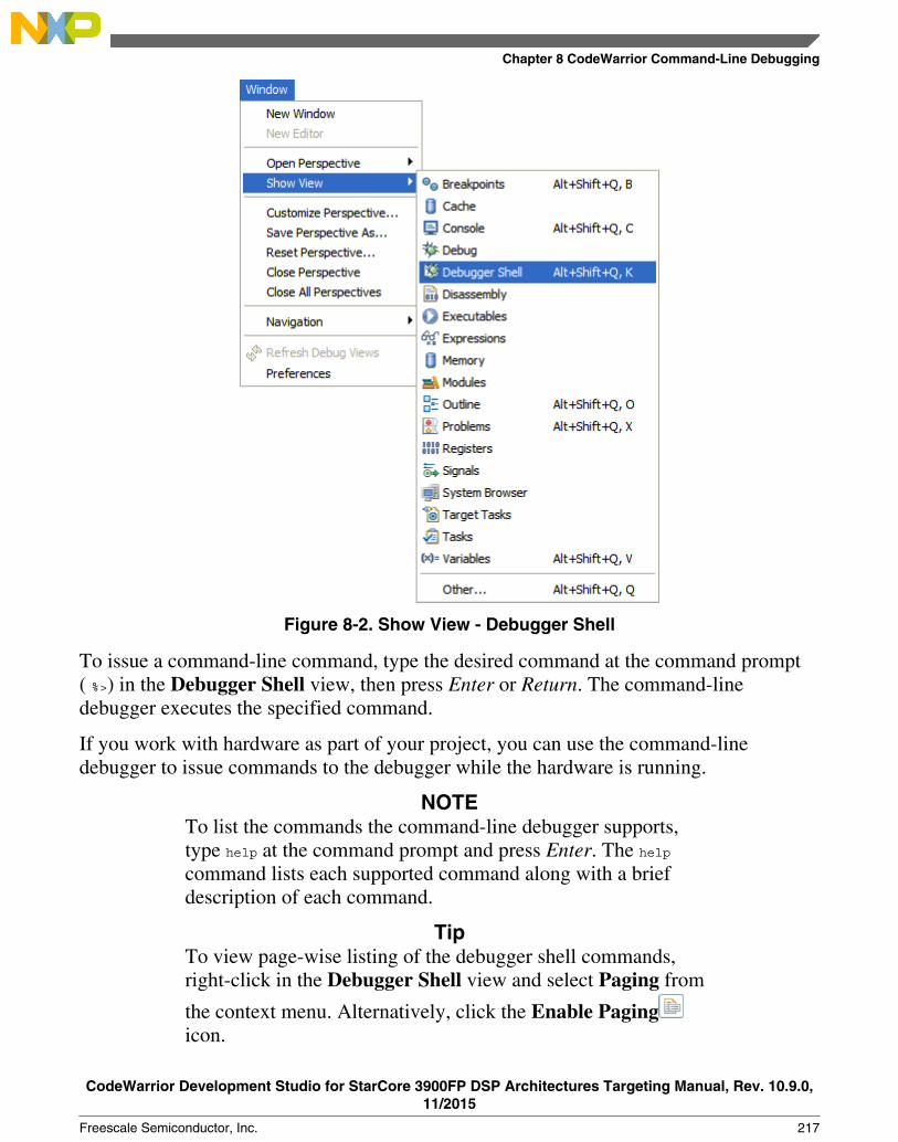
Figure 8-2. Show View - Debugger Shell
To issue a command-line command, type the desired command at the command prompt( %>) in the Debugger Shell view, then press Enter or Return. The command-linedebugger executes the specified command.
If you work with hardware as part of your project, you can use the command-linedebugger to issue commands to the debugger while the hardware is running.
NOTETo list the commands the command-line debugger supports,type help at the command prompt and press Enter. The helpcommand lists each supported command along with a briefdescription of each command.
TipTo view page-wise listing of the debugger shell commands,right-click in the Debugger Shell view and select Paging from
the context menu. Alternatively, click the Enable Pagingicon.
Chapter 8 CodeWarrior Command-Line Debugging
CodeWarrior Development Studio for StarCore 3900FP DSP Architectures Targeting Manual, Rev. 10.9.0,11/2015
Freescale Semiconductor, Inc. 217

8.2 Tcl Support
This section provides the following details on using the command-line debugger with Tclscript engine.
• Resolution of Conflicting Command Names• Execution of Script Files• Tcl Startup Script
8.2.1 Resolution of Conflicting Command Names
The names of several command-line debugger commands conflict with the Tclcommands.
The following table explains how the command-line debugger resolves such conflicts (ifthe mode is set to auto).
Table 8-1. Resolving Conflicting Commands
Command Resolution
bp If you pass the command-line debugger a bp command fromwithin a script and the command has arguments, thedebugger invokes the Tcl break command. Otherwise, thedebugger interprets a break command as a command tocontrol breakpoints.
8.2.2 Execution of Script Files
Tcl usually executes a script file as one large block, returning only after execution of theentire file.
For the run command, however, the command-line debugger executes script files line-by-line. If a particular line is not a complete Tcl command, the debugger appends the nextline. The debugger continues appending lines until it gets a complete Tcl script block.
Tcl Support
CodeWarrior Development Studio for StarCore 3900FP DSP Architectures Targeting Manual, Rev. 10.9.0,11/2015
218 Freescale Semiconductor, Inc.

The following listing lists code that includes a script. For the Tcl source command, thedebugger executes this script as one block. But for the run debug command, the debuggerexecutes this script as two blocks: the set statement and the while loop.
Listing: Example Tcl Script
set x 0;while {$x < 5}
{
puts "x is $x";
set x [expr $x + 1]
}
NOTEThe run debug command synchronizes debug events betweenblocks in a script file. For example, after a go, next, or stepcommand, run polls the debug thread state and does not executethe next line or block until the debug thread terminates.However, the Tcl source command does not consider the debugthread state. Consequently, use the run debug command toexecute script files that contain these debug commands: debug,go, next, stop, and kill.
8.2.3 Tcl Startup Script
The command-line debugger can automatically run a Tcl script each time you open thecommand-line debugger window.
This script is called a startup script.
You can use both Tcl and command-line debugger commands in the startup script. Forexample, you might include commands that set an alias or a define color configuration ina startup script.
To create a command-line debugger startup script, follow these steps:
1. Put the desired Tcl and command-line debugger commands in a text file.2. Name this file tcld.tcl.3. Place tcld.tcl in one of the directories listed below.
• On a Windows® PC, put tcld.tcl in the system directory.
Chapter 8 CodeWarrior Command-Line Debugging
CodeWarrior Development Studio for StarCore 3900FP DSP Architectures Targeting Manual, Rev. 10.9.0,11/2015
Freescale Semiconductor, Inc. 219

For example, put tcld.tcl in the WINDOWS directory.
• On a Solaris Workstation, put tcld.tcl in your home directory.
NOTEThere is no synchronization of debug events in thestartup script. Consequently, put the c debug commandto the startup script and place these debug commandsin another script so they will execute properly: debug,go, stop, kill, next, and step.
8.3 Command-Line Debugging Tasks
This section provides instructions for common command-line debugging tasks.
See the following table for details.
Table 8-2. Common Command-Line Debugging Tasks
Task Instruction Comments
Open the Debugger Shell Select Windows > Show View >Others > Debugger Shell.
The Debugger Shell view appears.
Use the help command 1. On the Debugger shell commandprompt (%>), type help. 2. Press Enter.
The Command List for the CodeWarriortool appears.
Enter a command 1. On the Debugger shell, type acommand followed by a space. 2. Typeany valid command-line options,separating each with a space. 3. PressEnter.
You can use shortcuts instead ofcomplete command names, such as kfor kill.
View debug command hints Type alias followed by a space The syntax for the rest of the commandappears.
Review previous commands Press Up Arrow and Down Arrow keys
Clear command from the command line Press the Esc key
Stop an executing script Press the Esc key
Toggle between insert/overwrite mode Press the Insert key
Scroll up/ down a page Press Page Up or Page Down key
Scroll left/right one column Press Ctrl-Left Arrow or Ctrl-Right Arrowkeys
Scroll to beginning or end of buffer Press Ctrl-Home or Ctrl-End keys
Command-Line Debugging Tasks
CodeWarrior Development Studio for StarCore 3900FP DSP Architectures Targeting Manual, Rev. 10.9.0,11/2015
220 Freescale Semiconductor, Inc.

8.4 Debugger Shell Command List
This section lists commands that are unique to the CodeWarrior tool.
The list of the commands that can be used in the CodeWarrior Debugger Shell view is asfollows:
NOTEFor information on the Tcl built-in commands, visit http://sourceforge.net/projects/tcl.
Table 8-3. Debugger Shell Command List
about alias bp
cd change cls
config copy debug
dir disassemble display
evaluate finish fl::blankcheck
fl::checksum fl::device fl::diagnose
fl::disconnect fl::dump fl::erase
fl::image fl::protect fl::secure
fl::target fl::verify fl::write
funcs getIDEpref getpid
go help history
jtagclock kill launch
loadsym log mc::config
mc::go mc::group mc::kill
mc::reset mc::restart mc::stop
mc::type mem next
nexti oneframe protocol
pwd quitIDE radix
redirect refresh reg
reset restart restore
run save sc::setMaxAccessLength
sc::setReset sc::getPhysicalAddress setpc
setpicloadaddr stack status
step stepi stop
switchtarget system var
wait watchpoint
Chapter 8 CodeWarrior Command-Line Debugging
CodeWarrior Development Studio for StarCore 3900FP DSP Architectures Targeting Manual, Rev. 10.9.0,11/2015
Freescale Semiconductor, Inc. 221

8.4.1 about
Lists the version information.
Syntax
about
8.4.2 alias
Creates an alias for a debug command, removes such an alias, or lists all current aliases.
Syntax
alias [<alias> [<command>]]
Parameters
alias
Lists current aliases.
Examples
Table 8-4 lists and defines examples of the alias command.
Table 8-4. alias Command-Line Debugger Command - Examples
Command Description
alias Lists current aliases.
alias ls dir Issue the dir command when ls is typed.
alias ls Remove the alias ls.
8.4.3 bp
Sets a breakpoint, removes a breakpoint, or lists the current breakpoints.
Syntax
bp [-{hw|sw|auto}] {<func>|[<ms>:]<addr>|<file> <line> [<column>]}
bp all|#<id>|<func>|<addr> off|enable|disable
Debugger Shell Command List
CodeWarrior Development Studio for StarCore 3900FP DSP Architectures Targeting Manual, Rev. 10.9.0,11/2015
222 Freescale Semiconductor, Inc.

Examples
Table 8-5 lists and defines examples of the bp command.
Table 8-5. bp Command-Line Debugger Command - Examples
Command Description
bp Lists all breakpoints.
bp -hw fn Set hardware breakpoint at function fn().
bp -autofile.cpp 101 1 Set an auto breakpoint on file file.cpp at line 101, column 1.
bp fn off Remove the breakpoint at function fn().
bp 10343 Set a breakpoint at memory address 10343.
bp #4 off Remove the breakpoint number 4.
bp #4 disable Disable the breakpoint number 4.
bp #4 cond x == 3 Set the condition for breakpoint number 4 to fire only if x == 3.
bp #4 cond Hit Count % 3 == 0 Break every third time. Hit Count corresponds to thebreakpoint property of the same name.
8.4.4 cd
Changes to a different directory or lists the current directory.
Pressing the Tab key completes the directory name automatically.
Syntax
cd [<path>]
Parameter
path
Directory pathname; accepts asterisks and wildcards.
Examples
Table 8-6 lists and defines examples of the cd command.
Table 8-6. cd Command-Line Debugger Command-Examples
Command Description
cd Lists current directory.
cd c: Changes to the C: drive root directory.
cd d:/mw/0622/ test Changes to the specified D: drive directory
cd c:p*s Changes to any C: drive directory whose name starts with pand ends with s.
Chapter 8 CodeWarrior Command-Line Debugging
CodeWarrior Development Studio for StarCore 3900FP DSP Architectures Targeting Manual, Rev. 10.9.0,11/2015
Freescale Semiconductor, Inc. 223

8.4.5 change
Changes the contents of register, memory location, block of registers, or memorylocations.
Syntax
change <addr-spec> [<range>] [-s|-ns] [%<conv>] <value>
change <addr-spec>{..<addr>|#<n>} [<range>] [-s|-ns] [%<conv>] <value>
change <reg-spec> [<n>] [-s|-ns] [%<conv>] <value>
change <reg-spec>{..<reg>|#<n>} [-s|-ns] [%<conv>] <value>
change <var-spec> [-s|-ns] [%<conv>] <value>
change v <var> [-s|-ns] [%<conv>] <value>
Parameter
<addr-spec> [<ms>:]<addr>
On architectures supporting multiple memory spaces, specifies the memory space inwhich <addr> is to be found.
See the help for the option -ms of display or mem for more information on memoryspaces. If unspecified, the setting config MemIdentifier is used.
<addr>
Target address in hex format.
<count>
Number of memory cells.
x<cell-size>
Memory is displayed in units called cells, where each cell consists of <cell-size> bytes. Ifunspecified, the setting config MemWidth is used.
h<access-size>
Memory is accessed with a hardware access size of <access-size> bytes.
If unspecified, the setting config MemWidth is used.
%<conv>
Debugger Shell Command List
CodeWarrior Development Studio for StarCore 3900FP DSP Architectures Targeting Manual, Rev. 10.9.0,11/2015
224 Freescale Semiconductor, Inc.

Specifies the type of the data. Possible values for <conv> are given below. The defaultconversion is set by the radix command for memory and registers and by the config varcommand for variables.
• %x Hexadecimal• %d Signed decimal• %u Unsigned decimal• %f Floating point
NOTEYou can not access array elements in Tcl except througharray and set commands. Therefore, to use the change or varcommand on an array element, enclose it in curly braces {}.
Examples
The examples assume the following settings:
• radix x
• config MemIdentifier 0
• config MemWidth 32
• config MemAccess 32
• config MemSwap off
Table 8-7 lists and defines Memory examples of the change command.
Table 8-7. change Command-Line Debugger Command-Memory Examples
Command Description
change 10000 10 Change memory range 0x10000-3 to 0x10 (because radixis hex).
change 1:10000 20 Change memory range 0x10000-3, memory space 1, to0x20.
change 10000 16 20 Change each of 16 cells in the memory range 0x10000-3fto 0x20.
change 10000 16x1h8 31 Change each of 16, 1-byte cells to 0x31, using a hardwareaccess size of 8-bytes per write.
change 10000 -s %d 200 Change memory range 0x10000-3 to c8000000.
change {x[1]} 10 Change the second element in the array x to the value 10.
change {t1.x} 2 Change the value of the variable x in the structure t1 to 2.
Chapter 8 CodeWarrior Command-Line Debugging
CodeWarrior Development Studio for StarCore 3900FP DSP Architectures Targeting Manual, Rev. 10.9.0,11/2015
Freescale Semiconductor, Inc. 225

Table 8-8 lists and defines Register examples of the change command.
Table 8-8. change Command-Line Debugger Command-Register Examples
Command Description
change R1 123 Change register R1 to 0x123.
change R1..R5 5432 Change registers R1 through R5 to 0x5432.
change "General Purpose Registers/R1" 100 Change register R1 in the General Purpose Register group to0x100.
Table 8-9 lists and defines Variable examples of the change command.
Table 8-9. change Command-Line Debugger Command-Variable Examples
Command Description
change myVar 10 Change the value of variable myVar to 16 (0x10)
8.4.6 cls
Clears the command line debugger window.
Syntax
cls
8.4.7 config
Lists current configuration information.
Provides the name of the default project or build target, or configures:
• command-line debugger window colors.• command-line debugger window scrolling size.• command-line debugger window mode.• Default build target• Hexadecimal prefix• Memory identifier• Processor name• Subprocessor name
Debugger Shell Command List
CodeWarrior Development Studio for StarCore 3900FP DSP Architectures Targeting Manual, Rev. 10.9.0,11/2015
226 Freescale Semiconductor, Inc.

Syntax
conf[ig] [ c[olor] [r | m | c | s | e | n]
text_color [background_color] |
m[ode] [ dsp | tcl | auto] |
s[croll] number_of_lines |
h[exprefix] hexadecimal_prefix |
mem[identifier] memory_identifier |
p[rocessor] processor_name [subprocessor_name] ]
Parameter
color text indicators -
r (registers), m (memory), c (commands), s (script), e (errors), or n (normal)
text_color
Text color values for red, green, and blue, each from 0 through 255.
background_color
Background color values for red, green, and blue, each from 0 through 255.
mode
Command-name conflict resolution mode:
• dsp: use command-line debug commands• tcl: use tcl commands• auto: resolve automatically
number_of_lines
Number of lines to scroll.
hexadecimal_prefix
Prefix for display of hexadecimal values.
memory_identifier
Memory identifier.
processor_name
Name or identifier of target processor.
subprocessor_name
Name or identifier of target subprocessor.
target_name
Chapter 8 CodeWarrior Command-Line Debugging
CodeWarrior Development Studio for StarCore 3900FP DSP Architectures Targeting Manual, Rev. 10.9.0,11/2015
Freescale Semiconductor, Inc. 227

Name of build target.
Examples
Table 8-10 lists and defines examples of the config command.
Table 8-10. config Command-Line Debugger Command-Examples
Command Description
config Lists current configuration information.
config c e $ff $0 $0 Sets error text to red.
config c r $0 $0 $0 $ff $ff $ff Sets register display to black, on a white background.
config m dsp Sets clash resolution to dsp mode.
config hexprefix 0x Specifies 0x prefix for hexadecimal values.
config memidentifier m Sets memory identifier to m.
config processor 8101 Sets processor to 8101.
config project Lists default-project name.
config target Lists default build-target name.
config target debug release x86 Changes default build-target name to debug release x86.
8.4.8 copy
Copies contents of a memory address or address block to another memory location.
Syntax
copy [<ms>:]<addr>[..<addr>|#<bytes>] [<ms>:]<addr>
Parameter
<addr>
One of these memory-address specifications:
• A single address• First address of the destination memory block.
Examples
Table 8-11 lists and defines examples of the copy command.
Table 8-11. copy Command-Line Debugger Command-Examples
Command Description
copy 00..1f 30 Copy memory addresses 00 through 1f to address 30.
Table continues on the next page...
Debugger Shell Command List
CodeWarrior Development Studio for StarCore 3900FP DSP Architectures Targeting Manual, Rev. 10.9.0,11/2015
228 Freescale Semiconductor, Inc.

Table 8-11. copy Command-Line Debugger Command-Examples (continued)
Command Description
copy 20#10 50 Copy 10 memory locations beginning at memory location 20to memory beginning at location 50.
8.4.9 debug
Launches a debug session.
Syntax
debug [<index> | <debug-config-name>]
Examples
Table 8-12 lists and defines examples of the debug command.
Table 8-12. debug Command-Line Debugger Command-Examples
Command Description
debug Start debugging using the default launch configuration, whichis the last debugged configuration if one exists and index 0otherwise.
debug 3 Start debugging using the launch configuration at index 3.Type launch for the current set of launch configurations.
debug {My Launch Config} Start debugging using the launch configuration named MyLaunch Config. Type launch for the current set of launchconfigurations.
8.4.10 dir
Lists directory contents.
Syntax
dir [path|files]
Examples
Chapter 8 CodeWarrior Command-Line Debugging
CodeWarrior Development Studio for StarCore 3900FP DSP Architectures Targeting Manual, Rev. 10.9.0,11/2015
Freescale Semiconductor, Inc. 229

Table 8-13 lists and defines examples of the dir command.
Table 8-13. dir Command-Line Debugger Command-Examples
Command Description
dir Lists all files of the current directory.
di *.txt Lists all current-directory files that have the .txt file nameextension.
dir c:/tmp Lists all files in the tmp directory on the C: drive.
dir /ad Lists only the subdirectories of the current directory.
8.4.11 disassemble
Disassembles the instructions of the specified memory block.
Syntax
disassemble
disassemble pc|[<ms>:]<addr> [<count>]
disassemble reset
disassemble [<ms>:]<a1>{..<a2>|#<n>}
Parameter
[none]
With no options, the next block of instructions is listed. After a target stop event, the nextblock starts at the PC.
[<ms>:]<addr>
Target address in hex. On targets with multiple memory spaces, a memory space id canbe specified.
pc
The current program counter.
<count>
Number of instructions to be listed.
reset
Reset the next block to the PC and the instruction count to one screen.
Debugger Shell Command List
CodeWarrior Development Studio for StarCore 3900FP DSP Architectures Targeting Manual, Rev. 10.9.0,11/2015
230 Freescale Semiconductor, Inc.
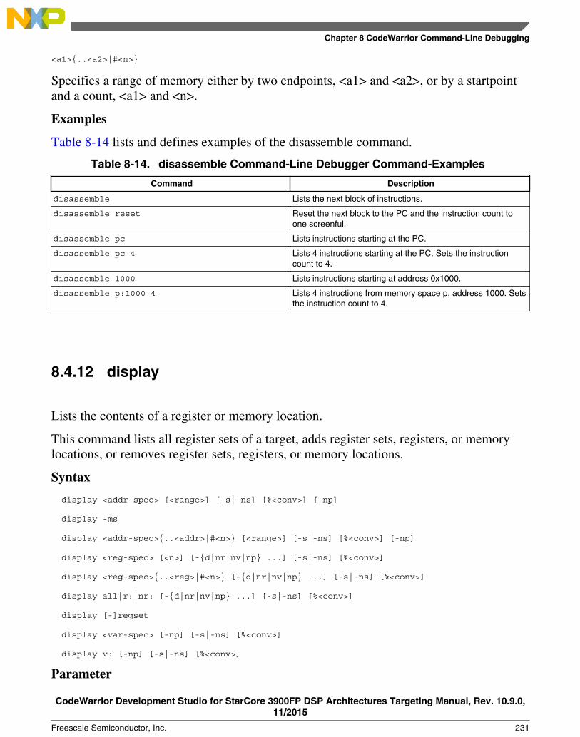
<a1>{..<a2>|#<n>}
Specifies a range of memory either by two endpoints, <a1> and <a2>, or by a startpointand a count, <a1> and <n>.
Examples
Table 8-14 lists and defines examples of the disassemble command.
Table 8-14. disassemble Command-Line Debugger Command-Examples
Command Description
disassemble Lists the next block of instructions.
disassemble reset Reset the next block to the PC and the instruction count toone screenful.
disassemble pc Lists instructions starting at the PC.
disassemble pc 4 Lists 4 instructions starting at the PC. Sets the instructioncount to 4.
disassemble 1000 Lists instructions starting at address 0x1000.
disassemble p:1000 4 Lists 4 instructions from memory space p, address 1000. Setsthe instruction count to 4.
8.4.12 display
Lists the contents of a register or memory location.
This command lists all register sets of a target, adds register sets, registers, or memorylocations, or removes register sets, registers, or memory locations.
Syntax
display <addr-spec> [<range>] [-s|-ns] [%<conv>] [-np]
display -ms
display <addr-spec>{..<addr>|#<n>} [<range>] [-s|-ns] [%<conv>] [-np]
display <reg-spec> [<n>] [-{d|nr|nv|np} ...] [-s|-ns] [%<conv>]
display <reg-spec>{..<reg>|#<n>} [-{d|nr|nv|np} ...] [-s|-ns] [%<conv>]
display all|r:|nr: [-{d|nr|nv|np} ...] [-s|-ns] [%<conv>]
display [-]regset
display <var-spec> [-np] [-s|-ns] [%<conv>]
display v: [-np] [-s|-ns] [%<conv>]
Parameter
Chapter 8 CodeWarrior Command-Line Debugging
CodeWarrior Development Studio for StarCore 3900FP DSP Architectures Targeting Manual, Rev. 10.9.0,11/2015
Freescale Semiconductor, Inc. 231

<ms>
On architectures supporting multiple memory spaces, specifies the memory space inwhich <addr> is to be found.
<addr>
Target address in hex.
<range>
[<count>][x<cell-size>][h<access-size>] | [<count>] [{8,16,32,64}bit].
<count>
Number of memory cells.
x<cell-size>
Memory is displayed in units called cells, where each cell consists of <cell-size> bytes. Ifunspecified, the setting config MemWidth is used.
{8,16,32,64}bit
Sets both <cell-size> and <access-size>.
Examples
The examples assume the following settings:
• radix x
• config MemIdentifier 0
• config MemWidth 32
• config MemAccess 32
• config MemSwap off
Table 8-15 lists and defines examples of the display command.
Table 8-15. display Command-Line Debugger Command-Examples
Command Description
display 10000 Display memory range 0x10000-3 as one cell.
display 1:10000 Display memory range 0x10000-3, memory space 1, as onecell.
display 10000 16 Display memory range 0x10000-3f as 16 cells.
display 10000 16x1h8 Display 16, 1-byte cells, with a hardware access size of 8-bytes per read.
display 10000 8bit Display one byte, with a hardware access size of one byte.
display 10000 -np Return one cell, but don't print it to the Command Window.
display 10000 -s Display one cell with the data endian-swapped.
display 10000 %d Display one cell in decimal format.
Table continues on the next page...
Debugger Shell Command List
CodeWarrior Development Studio for StarCore 3900FP DSP Architectures Targeting Manual, Rev. 10.9.0,11/2015
232 Freescale Semiconductor, Inc.

Table 8-15. display Command-Line Debugger Command-Examples (continued)
Command Description
display -ms Display the available memory spaces, if any.
display -regset List all the available register sets on the target chip.
display R1 Display the value of register R1.
display "General Purpose Registers/R1" Display the value of register R1 in the General PurposeRegister group.
display R1 -d Display detailed "data book" contents of R1, including bitfieldsand definitions.
display "nr:General Purpose Registers/R1" 25 Beginning with register R1, display the next 25 registers.Register groups are not recursively searched.
8.4.13 evaluate
Lists variable or expression.
Syntax
evaluate [#<format>] [-l] [<var|expr>]
Parameter
<format>
Output format and possible values:
#-, #Default
#d, #Signed
#u, #Unsigned
#h, #x, #Hex
#c, #Char
#s, #CString
#p, #PascalString
#f, #Float
#e, #Enum
#i, #Fixed
#o, #w, #Unicode
#b, #Binary
<none>, #Fract
Chapter 8 CodeWarrior Command-Line Debugging
CodeWarrior Development Studio for StarCore 3900FP DSP Architectures Targeting Manual, Rev. 10.9.0,11/2015
Freescale Semiconductor, Inc. 233

<none>, #Boolean
<none>, #SignedFixed
Examples
Table 8-16 lists and defines examples of the evaluate command.
Table 8-16. evaluate Command-Line Debugger Command-Examples
Command Description
evaluate List the types for all the variables in current and global stack.
evaluate i Return the value of variable 'i'
evaluate #b i Return the value of variable 'i' formatted in binary
evaluate -l 10 Return the address for line 10 in the current file
evaluate -l myfile.c,10 Return the address for line 10 in file myfile.c
evaluate -l +10 Return the address to an offset of 10 lines starting from thecurrent line
8.4.14 finish
Executes until the current function returns.
Syntax
finish
8.4.15 fl::blankcheck
Tests that the flash device is in the blank state.
Syntax
fl::blankcheck
8.4.16 fl::checksum
Calculates a checksum.
Syntax
Debugger Shell Command List
CodeWarrior Development Studio for StarCore 3900FP DSP Architectures Targeting Manual, Rev. 10.9.0,11/2015
234 Freescale Semiconductor, Inc.

fl::checksum
8.4.17 fl::device
Defines the flash device.
Syntax
fl::device
8.4.18 fl::diagnose
Dumps flash information like ID, sector map, sector factory, protect status.
Syntax
fl::diagnose [full]
Parameter
full
Dumps sector status (programmed/erased). This could take a few minutes for largeflashes
Remarks
Use fl::device command prior to this command in order to set the flash device.
8.4.19 fl::disconnect
Closes the connection to the target.
Syntax
fl::disconnect
8.4.20 fl::dump
Chapter 8 CodeWarrior Command-Line Debugging
CodeWarrior Development Studio for StarCore 3900FP DSP Architectures Targeting Manual, Rev. 10.9.0,11/2015
Freescale Semiconductor, Inc. 235
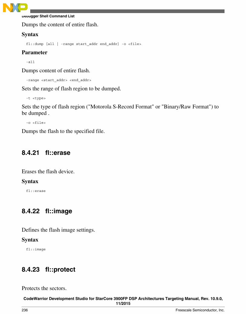
Dumps the content of entire flash.
Syntax
fl::dump [all | -range start_addr end_addr] -o <file>
Parameter
-all
Dumps content of entire flash.
-range <start_addr> <end_addr>
Sets the range of flash region to be dumped.
-t <type>
Sets the type of flash region ("Motorola S-Record Format" or "Binary/Raw Format") tobe dumped .
-o <file>
Dumps the flash to the specified file.
8.4.21 fl::erase
Erases the flash device.
Syntax
fl::erase
8.4.22 fl::image
Defines the flash image settings.
Syntax
fl::image
8.4.23 fl::protect
Protects the sectors.
Debugger Shell Command List
CodeWarrior Development Studio for StarCore 3900FP DSP Architectures Targeting Manual, Rev. 10.9.0,11/2015
236 Freescale Semiconductor, Inc.

Syntax
fl::protect [on | off]
Parameter
on | off
Enable or disable protection of sectors.
8.4.24 fl::secure
Secures the device
Syntax
fl::secure [on | off] [password <pass>]
Parameter
on | off
Secure or unsecure device.
password <pass>
Password used to secure the device.
8.4.25 fl::target
Defines the target configuration settings.
Syntax
fl::target
8.4.26 fl::verify
Verifies the flash device.
Syntax
fl::verify
Chapter 8 CodeWarrior Command-Line Debugging
CodeWarrior Development Studio for StarCore 3900FP DSP Architectures Targeting Manual, Rev. 10.9.0,11/2015
Freescale Semiconductor, Inc. 237

8.4.27 fl::write
Writes the flash device.
Syntax
fl::write
8.4.28 funcs
Displays information about functions.
Syntax
funcs [-all] <file> <line>
Parameter
[-all]
Displays information about the functions using all debug contexts.
<file>
Specifies the file name.
<line>
Specifies the line number.
Examples
Table 8-17 lists and defines examples of the funcs command.
Table 8-17. funcs Command-Line Debugger Command-Examples
Command Description
funcs main.c 100 Display information about the functions containing line 100 infile main.c, using the active debug context
funcs -all main.c 100 Display information about the functions containing line 100 infile main.c, using all debug contexts.
Debugger Shell Command List
CodeWarrior Development Studio for StarCore 3900FP DSP Architectures Targeting Manual, Rev. 10.9.0,11/2015
238 Freescale Semiconductor, Inc.

8.4.29 getIDEpref
The command displays the value of the launch configuration attribute associated with theuser-provided key; <attribute_key> and <attribute_type> are mandatory parameters.
Syntax
getIDEpref <attribute_key> <attribute_type>
Parameter
<attribute_type> = [bool | int | str | strlist]
8.4.30 getpid
List the ID of the process being debugged.
Syntax
getpid
8.4.31 go
Starts to debug your program from the current instruction.
Syntax
go [nowait | <timeout_s>]
Parameter
<none>
Run the default thread. The command may wait for a thread break event before returning,depending on the settings config runControlSync and config autoThreadSwitch.
nowait
Return immediately without waiting for a thread break event.
<timeout_s>
Maximum number of seconds to wait for a thread break event. Can be set to nowait.
Examples
Chapter 8 CodeWarrior Command-Line Debugging
CodeWarrior Development Studio for StarCore 3900FP DSP Architectures Targeting Manual, Rev. 10.9.0,11/2015
Freescale Semiconductor, Inc. 239
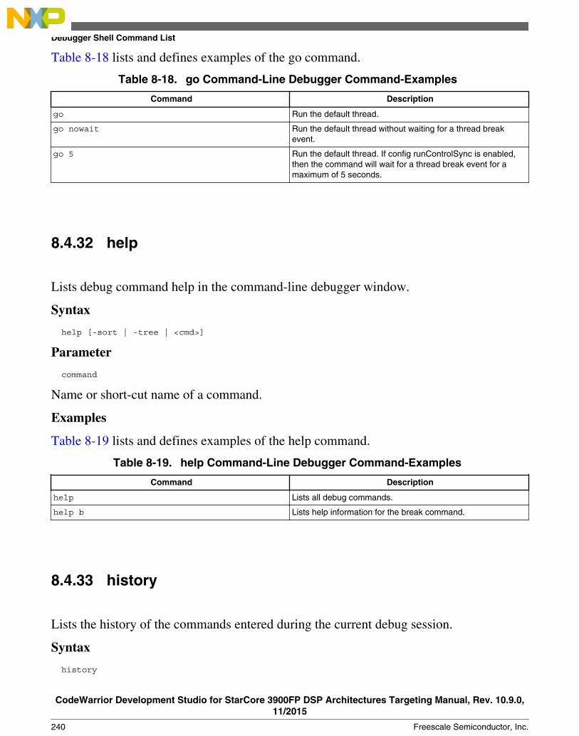
Table 8-18 lists and defines examples of the go command.
Table 8-18. go Command-Line Debugger Command-Examples
Command Description
go Run the default thread.
go nowait Run the default thread without waiting for a thread breakevent.
go 5 Run the default thread. If config runControlSync is enabled,then the command will wait for a thread break event for amaximum of 5 seconds.
8.4.32 help
Lists debug command help in the command-line debugger window.
Syntax
help [-sort | -tree | <cmd>]
Parameter
command
Name or short-cut name of a command.
Examples
Table 8-19 lists and defines examples of the help command.
Table 8-19. help Command-Line Debugger Command-Examples
Command Description
help Lists all debug commands.
help b Lists help information for the break command.
8.4.33 history
Lists the history of the commands entered during the current debug session.
Syntax
history
Debugger Shell Command List
CodeWarrior Development Studio for StarCore 3900FP DSP Architectures Targeting Manual, Rev. 10.9.0,11/2015
240 Freescale Semiconductor, Inc.

8.4.34 jtagclock
Reads or updates the current JTAG clock speed.
Syntax
jtagclock <chain-position> [<speed-in-kHz>]
Parameter
<chain-position>
Specifies the chain position.
<speed-in-kHz>
Specifies the speed in kilo hertz.
Examples
Table 8-20 lists and defines examples of the help command.
Table 8-20. jtagclock Command-Line Debugger Command-Examples
Command Description
jtagclock 3 Read the current jtag clock speed for chain position 3.
jtagclock 3 1000 update the current jtag clock speed to 1000 kHz for chainposition 3.
8.4.35 kill
Stops one or all current debug sessions.
Syntax
kill [<index> ...]
Parameter
all
Specifier for all debug sessions.
Examples
Chapter 8 CodeWarrior Command-Line Debugging
CodeWarrior Development Studio for StarCore 3900FP DSP Architectures Targeting Manual, Rev. 10.9.0,11/2015
Freescale Semiconductor, Inc. 241
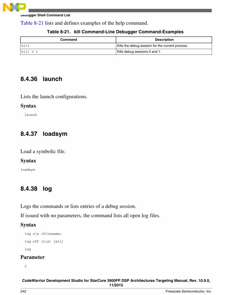
Table 8-21 lists and defines examples of the help command.
Table 8-21. kill Command-Line Debugger Command-Examples
Command Description
kill Kills the debug session for the current process.
kill 0 1 Kills debug sessions 0 and 1.
8.4.36 launch
Lists the launch configurations.
Syntax
launch
8.4.37 loadsym
Load a symbolic file.
Syntax
loadsym
8.4.38 log
Logs the commands or lists entries of a debug session.
If issued with no parameters, the command lists all open log files.
Syntax
log c|s <filename>
log off [c|s] [all]
log
Parameter
c
Debugger Shell Command List
CodeWarrior Development Studio for StarCore 3900FP DSP Architectures Targeting Manual, Rev. 10.9.0,11/2015
242 Freescale Semiconductor, Inc.

Command specifier.
s
Lists entry specifier.
<filename>
Name of a log file.
Examples
Table 8-22 lists and defines examples of the log command.
Table 8-22. log Command-Line Debugger Command-Examples
Command Description
log Lists currently opened log files.
log s session.log Log all display entries to file session.log.
log off c Close current command log file.
log off Close current command and log file.
log off all Close all log files.
8.4.39 mc::config
List or edit multicore group options.
Syntax
mc::config
8.4.40 mc::go
Resumes multiple cores.
Syntax
mc::go
Examples
Chapter 8 CodeWarrior Command-Line Debugging
CodeWarrior Development Studio for StarCore 3900FP DSP Architectures Targeting Manual, Rev. 10.9.0,11/2015
Freescale Semiconductor, Inc. 243
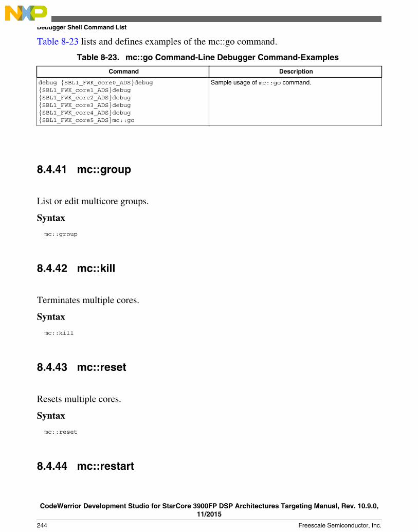
Table 8-23 lists and defines examples of the mc::go command.
Table 8-23. mc::go Command-Line Debugger Command-Examples
Command Description
debug {SBL1_FWK_core0_ADS}debug{SBL1_FWK_core1_ADS}debug{SBL1_FWK_core2_ADS}debug{SBL1_FWK_core3_ADS}debug{SBL1_FWK_core4_ADS}debug{SBL1_FWK_core5_ADS}mc::go
Sample usage of mc::go command.
8.4.41 mc::group
List or edit multicore groups.
Syntax
mc::group
8.4.42 mc::kill
Terminates multiple cores.
Syntax
mc::kill
8.4.43 mc::reset
Resets multiple cores.
Syntax
mc::reset
8.4.44 mc::restart
Debugger Shell Command List
CodeWarrior Development Studio for StarCore 3900FP DSP Architectures Targeting Manual, Rev. 10.9.0,11/2015
244 Freescale Semiconductor, Inc.
Restarts multiple cores.
Syntax
mc::restart
8.4.45 mc::stop
Suspend multiple cores.
Syntax
mc::stop
8.4.46 mc::type
List or edit system types.
Syntax
mc::type
8.4.47 mem
Read and write one or more adjacent "cells" of memory, where a cell is defined as acontiguous block of bytes.
The cell size is determined by the <cell-size> parameter or by the using MemWidth attributeof the config command.
Syntax
Read memory
mem <addr-spec> [<range>] [-s|-ns] [%<conv>] [-np]
Write memory
mem <addr-spec> [<range>] [-s|-ns] [%<conv>] =<value>
Parameter
[none]
Chapter 8 CodeWarrior Command-Line Debugging
CodeWarrior Development Studio for StarCore 3900FP DSP Architectures Targeting Manual, Rev. 10.9.0,11/2015
Freescale Semiconductor, Inc. 245

With no options, the next block of memory is read.
<addr-spec> [<ms>:]<addr>
<ms>
On architectures supporting multiple memory spaces, specifies the memory space inwhich <addr> is to be found. See the help for the option -ms of display or mem for moreinformation on memory spaces. If unspecified, the setting " config MemIdentifier" is used.
<addr>
Target address in hex.
<range> [<count>][x<cell-size>][h<access-size>] | [<count>] [{8,16,32,64}bit]
<count>
Number of memory cells.
x<cell-size>
Memory is displayed in units called cells, where each cell consists of <cell-size> bytes. Ifunspecified, the setting " config MemWidth" is used.
h<access-size>
Memory is accessed with a hardware access size of <access-size> bytes. If unspecified,the setting " config MemAccess" is used.
{8,16,32,64}bit
Sets both <cell-size> and <access-size>.
-np
Don't print anything to the display, only return the data.
-ms
On architectures supporting multiple memory spaces, displays the list of availablememory spaces including a mnemonic and/or an integer index which may be used whenspecifying a target address.
-s|-ns
Specifies whether each value is to be swapped. For memory, specifies whether each cellis to be swapped. With a setting of -ns, target memory is written in order from lowest tohighest byte address. Otherwise, each cell is endian swapped. If unspecified, the settingconfig MemSwap is used.
%<conv>
Debugger Shell Command List
CodeWarrior Development Studio for StarCore 3900FP DSP Architectures Targeting Manual, Rev. 10.9.0,11/2015
246 Freescale Semiconductor, Inc.
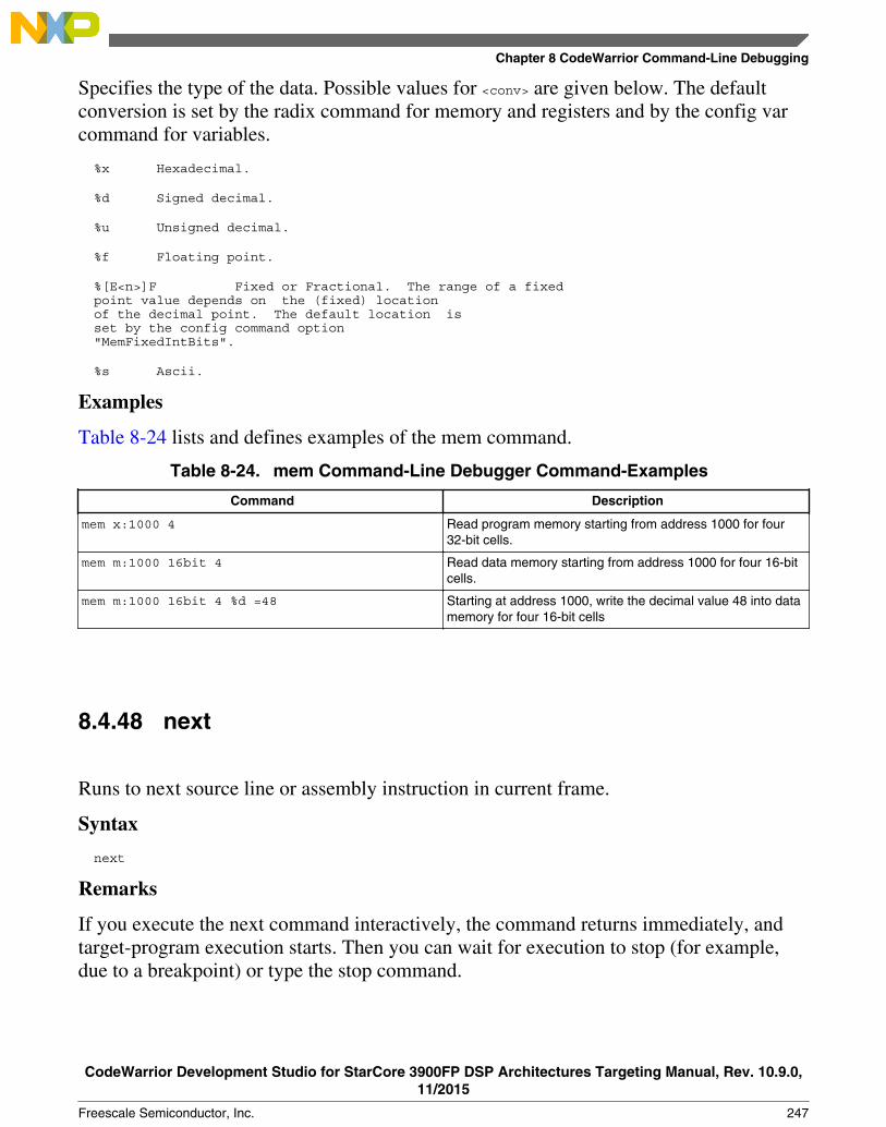
Specifies the type of the data. Possible values for <conv> are given below. The defaultconversion is set by the radix command for memory and registers and by the config varcommand for variables.
%x Hexadecimal.
%d Signed decimal.
%u Unsigned decimal.
%f Floating point.
%[E<n>]F Fixed or Fractional. The range of a fixed point value depends on the (fixed) location of the decimal point. The default location is set by the config command option "MemFixedIntBits".
%s Ascii.
Examples
Table 8-24 lists and defines examples of the mem command.
Table 8-24. mem Command-Line Debugger Command-Examples
Command Description
mem x:1000 4 Read program memory starting from address 1000 for four32-bit cells.
mem m:1000 16bit 4 Read data memory starting from address 1000 for four 16-bitcells.
mem m:1000 16bit 4 %d =48 Starting at address 1000, write the decimal value 48 into datamemory for four 16-bit cells
8.4.48 next
Runs to next source line or assembly instruction in current frame.
Syntax
next
Remarks
If you execute the next command interactively, the command returns immediately, andtarget-program execution starts. Then you can wait for execution to stop (for example,due to a breakpoint) or type the stop command.
Chapter 8 CodeWarrior Command-Line Debugging
CodeWarrior Development Studio for StarCore 3900FP DSP Architectures Targeting Manual, Rev. 10.9.0,11/2015
Freescale Semiconductor, Inc. 247
If you execute the next command in a script, the command-line debugger polls until thedebugger stops (for example, due to a breakpoint). Then the command line debuggerexecutes the next command in the script. If this polling continues indefinitely becausedebugging does not stop, press the ESC key to stop the script.
8.4.49 nexti
Executes over function calls, if any, to the next assembly instruction.
Syntax
nexti
8.4.50 oneframe
Query or set the one-frame stack crawl mode for the current thread.
Syntax
oneframe
8.4.51 protocol
Executes a protocol plugin command (internal).
Syntax
protocol
8.4.52 pwd
Lists current working directory.
Syntax
pwd
Debugger Shell Command List
CodeWarrior Development Studio for StarCore 3900FP DSP Architectures Targeting Manual, Rev. 10.9.0,11/2015
248 Freescale Semiconductor, Inc.

8.4.53 quitIDE
Quits the IDE.
Syntax
quitIDE
8.4.54 radix
Lists or changes the default input radix (number base) for command entries, registers andmemory locations.
Entering this command without any parameter values lists the current default radix.
Syntax
radix [x|d|u|b|f|h]
Parameter
x
Hexadecimal
d
Decimal
u
Unsigned decimal
b
Binary
f
Fractional
h
Hexadecimal
Examples
Chapter 8 CodeWarrior Command-Line Debugging
CodeWarrior Development Studio for StarCore 3900FP DSP Architectures Targeting Manual, Rev. 10.9.0,11/2015
Freescale Semiconductor, Inc. 249

Table 8-25 lists and defines examples of the radix command.
Table 8-25. radix Command-Line Debugger Command-Examples
Command Description
radix Lists the current setting.
radix d Change the setting to decimal.
radix x Change the setting to hexadecimal.
8.4.55 redirect
Redirects I/O streams of the current target process.
Syntax
redirect
8.4.56 refresh
Discard all cached target data and refresh views.
Syntax
refresh
8.4.57 reg
Read and write registers.
Syntax
reg
8.4.58 reset
Reset the target hardware.
Debugger Shell Command List
CodeWarrior Development Studio for StarCore 3900FP DSP Architectures Targeting Manual, Rev. 10.9.0,11/2015
250 Freescale Semiconductor, Inc.

Syntax
reset
8.4.59 restart
Restarts the current debug session.
Syntax
restart
8.4.60 restore
Write file contents to memory.
Syntax
restore
8.4.61 run
Launch a process.
Syntax
run
8.4.62 save
Saves the contents of memory locations to a binary file or a text file containinghexadecimal values.
Syntax
save -h|-b [<ms>:]<addr>... <filename> [-a|-o] [8bit|16bit|32bit|64bit]
Parameter
Chapter 8 CodeWarrior Command-Line Debugging
CodeWarrior Development Studio for StarCore 3900FP DSP Architectures Targeting Manual, Rev. 10.9.0,11/2015
Freescale Semiconductor, Inc. 251
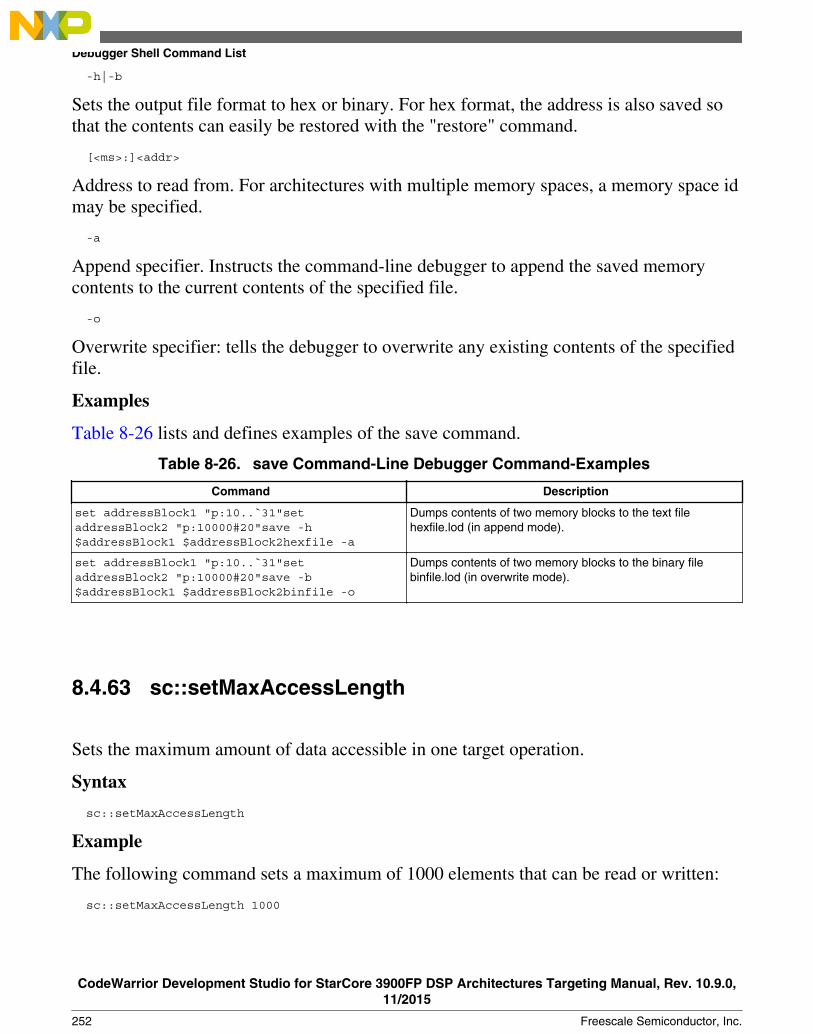
-h|-b
Sets the output file format to hex or binary. For hex format, the address is also saved sothat the contents can easily be restored with the "restore" command.
[<ms>:]<addr>
Address to read from. For architectures with multiple memory spaces, a memory space idmay be specified.
-a
Append specifier. Instructs the command-line debugger to append the saved memorycontents to the current contents of the specified file.
-o
Overwrite specifier: tells the debugger to overwrite any existing contents of the specifiedfile.
Examples
Table 8-26 lists and defines examples of the save command.
Table 8-26. save Command-Line Debugger Command-Examples
Command Description
set addressBlock1 "p:10..`31"setaddressBlock2 "p:10000#20"save -h$addressBlock1 $addressBlock2hexfile -a
Dumps contents of two memory blocks to the text filehexfile.lod (in append mode).
set addressBlock1 "p:10..`31"setaddressBlock2 "p:10000#20"save -b$addressBlock1 $addressBlock2binfile -o
Dumps contents of two memory blocks to the binary filebinfile.lod (in overwrite mode).
8.4.63 sc::setMaxAccessLength
Sets the maximum amount of data accessible in one target operation.
Syntax
sc::setMaxAccessLength
Example
The following command sets a maximum of 1000 elements that can be read or written:
sc::setMaxAccessLength 1000
Debugger Shell Command List
CodeWarrior Development Studio for StarCore 3900FP DSP Architectures Targeting Manual, Rev. 10.9.0,11/2015
252 Freescale Semiconductor, Inc.

8.4.64 sc::setReset
Sets the reset mode.
Syntax
sc::setReset <mode>
Parameter
<mode>
Can be ToUser or ToDebug. ToUser sets the reset to run out of reset. For debug mode afterreset, use ToDebug parameter.
8.4.65 sc::getPhysicalAddress
Returns the physical address that corresponds to the specified virtual address.
Use mem –ms command, to view the list of supported memory spaces. For moreinformation, refer to the mem command.
Syntax
sc::getPhysicalAddress <mem_space>:<virtual_address>
8.4.66 setpc
Set the value of the program counter register.
Syntax
setpc
8.4.67 setpicloadaddr
Indicate where a PIC executable is loaded.
Chapter 8 CodeWarrior Command-Line Debugging
CodeWarrior Development Studio for StarCore 3900FP DSP Architectures Targeting Manual, Rev. 10.9.0,11/2015
Freescale Semiconductor, Inc. 253

Syntax
setpicloadaddr
8.4.68 stack
Print the call stack.
Syntax
stack
8.4.69 status
Lists the debug status of all existing active targets.
Syntax
status
8.4.70 step
Steps through a program, automatically executing the display command.
Syntax
step [asm|src] [into|over|out]
step [nve|nxt|fwd|end|aft]
Parameter
asm|src
Controls whether the step is performed at the assembly instruction level or the sourcecode level.
into|over|out
Controls the type of step operation. If unspecified, into is used.
nve
Step non optimized action.
Debugger Shell Command List
CodeWarrior Development Studio for StarCore 3900FP DSP Architectures Targeting Manual, Rev. 10.9.0,11/2015
254 Freescale Semiconductor, Inc.

nxt
Step next action.
fwd
Step forward action.
end
Step end of statement action.
aft
Step end all previous action.
Examples
Table 8-27 lists and defines examples of the step command.
Table 8-27. step Command-Line Debugger Command-Examples
Command Description
step Step into the current source or assembly line.
step over Step over the current source or assembly line.
step out Step out of a function.
step asm Step over a single assembly instruction.
8.4.71 stepi
Execute to the next assembly instruction.
Syntax
stepi
8.4.72 stop
Stops a running program (started by a go, step, or next command).
Syntax
stop
Examples
Chapter 8 CodeWarrior Command-Line Debugging
CodeWarrior Development Studio for StarCore 3900FP DSP Architectures Targeting Manual, Rev. 10.9.0,11/2015
Freescale Semiconductor, Inc. 255

Table 8-28 lists and defines examples of the stop command.
Table 8-28. stop Command-Line Debugger Command-Examples
Command Description
stop Using it after command go/step out/next, this will stop thetarget program.
8.4.73 switchtarget
Chooses a thread for subsequent commands.
Syntax
switchtarget [<index> | -cur | -ResetIndex]
Parameter
index
Session Index number.
Examples
Table 8-29 lists and defines examples of the switchtarget command.
Table 8-29. switchtarget Command-Line Debugger Command-Examples
Command Description
switchtarget list currently available debug sessions.
switchtarget 0 choose the thread with index 0
switchtarget -cur list the index of the current thread.
switchtarget -ResetIndex reset the index counter to 0, not valid while debugging.
8.4.74 system
execute system command.
Syntax
system [command]
Parameter
Debugger Shell Command List
CodeWarrior Development Studio for StarCore 3900FP DSP Architectures Targeting Manual, Rev. 10.9.0,11/2015
256 Freescale Semiconductor, Inc.
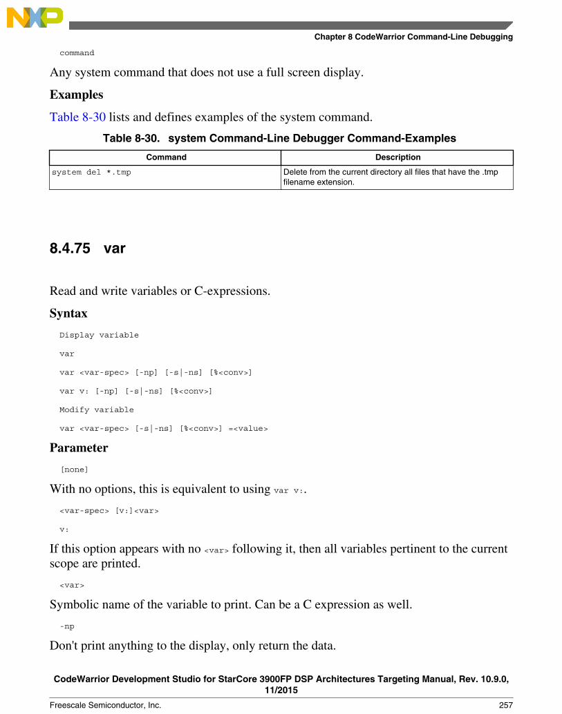
command
Any system command that does not use a full screen display.
Examples
Table 8-30 lists and defines examples of the system command.
Table 8-30. system Command-Line Debugger Command-Examples
Command Description
system del *.tmp Delete from the current directory all files that have the .tmpfilename extension.
8.4.75 var
Read and write variables or C-expressions.
Syntax
Display variable
var
var <var-spec> [-np] [-s|-ns] [%<conv>]
var v: [-np] [-s|-ns] [%<conv>]
Modify variable
var <var-spec> [-s|-ns] [%<conv>] =<value>
Parameter
[none]
With no options, this is equivalent to using var v:.
<var-spec> [v:]<var>
v:
If this option appears with no <var> following it, then all variables pertinent to the currentscope are printed.
<var>
Symbolic name of the variable to print. Can be a C expression as well.
-np
Don't print anything to the display, only return the data.
Chapter 8 CodeWarrior Command-Line Debugging
CodeWarrior Development Studio for StarCore 3900FP DSP Architectures Targeting Manual, Rev. 10.9.0,11/2015
Freescale Semiconductor, Inc. 257

-s|-ns
Specifies whether each value is to be swapped. For memory, specifies whether each cellis to be swapped. With a setting of -ns, target memory is written in order from lowest tohighest byte address. Otherwise, each cell is endian swapped. If unspecified, the settingconfig MemSwap is used.
%<conv>
Specifies the type of the data. Possible values for <conv> are given below. The defaultconversion is set by the radix command for memory and registers and by the config varcommand for variables.
%x Hexadecimal.
%d Signed decimal.
%u Unsigned decimal.
%f Floating point.
%[E<n>]F Fixed or Fractional. The range of a fixed point value depends on the (fixed) location of the decimal point. The default location is set by the config command option "MemFixedIntBits".
%s Ascii.
Examples
Table 8-31 lists and defines examples of the var command.
Table 8-31. var Command-Line Debugger Command-Examples
Command Description
var flag =0 Set the value of the variable flag to 0.
var {x[2]} =11 Set the value of the third element in the array x to 11.
var {t1.y} =3 Set the value of the variable y in the structure t1 to 3.
8.4.76 wait
Tells the debugger to wait for a specified amount of time, or until you press the space bar.
Syntax
wait <time-ms>
Parameter
time-ms
Debugger Shell Command List
CodeWarrior Development Studio for StarCore 3900FP DSP Architectures Targeting Manual, Rev. 10.9.0,11/2015
258 Freescale Semiconductor, Inc.

Number of milliseconds to wait.
Examples
Table 8-32 lists and defines examples of the wait command.
Table 8-32. wait Command-Line Debugger Command-Examples
Command Description
wait Debugger waits until you press the space bar.
wait 2000 Wait for 2 seconds.
8.4.77 watchpoint
Sets, removes, disables, enables or list watchpoints. You can also set condition onwatchpoint.
Syntax
watchpoint
watchpoint [-{r|w|rw}] {<var>|[<ms>:]<addr> <length>}
watchpoint all|#<id>|<var>|[<ms>:]<addr> off|enable|disable
watchpoint #<id> cond <c-expr>
Examples
Table 8-33 lists and defines examples of the watchpoint command.
Table 8-33. watchpoint Command-Line Debugger Command-Examples
Command Description
watchpoint Display all watchpoints.
watchpoint gData Set read-write (the default) watchpoint on variable gData.
watchpoint -r gData Set read-only watchpoint on variable gData.
watchpoint all off Remove all watchpoints.
watchpoint #4 disable Disable watchpoint number 4.
watchpoint 10343 4 Set a watchpoint at memory address 10343 of length 4.
Chapter 8 CodeWarrior Command-Line Debugging
CodeWarrior Development Studio for StarCore 3900FP DSP Architectures Targeting Manual, Rev. 10.9.0,11/2015
Freescale Semiconductor, Inc. 259

Debugger Shell Command List
CodeWarrior Development Studio for StarCore 3900FP DSP Architectures Targeting Manual, Rev. 10.9.0,11/2015
260 Freescale Semiconductor, Inc.

Chapter 9Multi-Core Debugging
This chapter explains how to use the multi-core debugging capability of the CodeWarriordebugger.
In this chapter:
• Creating a JTAG Initialization File• Debugging Multi-Core Projects• Multi-Core Debugging Commands
9.1 Creating a JTAG Initialization File
This section explains how to create a JTAG initialization file that specifies the type andchain order of the cores you want to debug.
The listing below shows the JTAG initialization file for a StarCore processor and ageneric device, connected to a JTAG chain.
Listing 9-1. JTAG Initialization File for Generic Device Connected to JTAG Chain
# JTAG Initialization File#
# Standards for this file
# 1. Comments begin with the character '#'.
# 2. A StarCore device is specified with:
# B4860
# 3. A non-StarCore device is specified with:
# Generic <Value_1> <Value_2> <Value_3>
# Value_1 is the length in bits of the JTAG instruction register.
# Value_2 is the length in bits of the JTAG bypass register.
CodeWarrior Development Studio for StarCore 3900FP DSP Architectures Targeting Manual, Rev. 10.9.0,11/2015
Freescale Semiconductor, Inc. 261

# Value_3 is the hex value of the JTAG bypass instruction.
# Hex values are prefixed with 0x.
# 4. Each device is specified on a new line.
# 5. Device specification is case sensitive, and a Generic device
# cannot be specified without all three values.
#
#An example configuration is shown below:
B4860
Generic 4 1 Oxf
You can also include entries for other StarCore, non-StarCore devices connected to theJTAG chain by adding the following lines of code to your JTAG initialization file:
Generic instruct_reg_len data_reg_bypass_len JTAG_bypass_instruct
The table below shows the variable definitions that you must specify for a generic device.
Table 9-1. Syntax Variables to Specify Generic Device on JTAG Chain
Variable Description
instruct_reg_len Length (in bits) of the JTAG instruction register.
data_reg_bypass_len Length (in bits) of the JTAG bypass register.
JTAG_bypass_instruct Value of the JTAG bypass instruction (in hexadecimal).
9.2 Debugging Multi-Core Projects
This section explains how to set launch configurations and how to debug multiple coresin a multi-core project.
The CodeWarrior debugger provides the facility to debug multiple StarCore processorsusing a single debug environment. The run control operations can be operatedindependently or synchronously. A common debug kernel facilitates multi-core, runcontrol debug operations for examining and debugging the interaction of the softwarerunning on the different cores on the system.
Debugging Multi-Core Projects
CodeWarrior Development Studio for StarCore 3900FP DSP Architectures Targeting Manual, Rev. 10.9.0,11/2015
262 Freescale Semiconductor, Inc.

NOTEThis procedure assumes that you have already created a multi-core project, named board_project.
To debug multiple cores connected to a JTAG chain, perform the steps given in thefollowing sections:
• Setting Launch Configurations• Debugging Multiple Cores
9.2.1 Setting Launch Configurations
Setting a launch configuration allows you to specify all core-specific initializations.
To set up the launch configurations, follow these steps:
1. Connect to your JTAG chain.
NOTEThe JTAG chain includes multiple boards or multipleprocessors on the same or multiple boards.
2. Create a JTAG initialization file that describes the items on the JTAG chain. Formore information on how to create a JTAG initialization file, see Creating a JTAGInitialization File.
3. Open the CodeWarrior project you want to debug.4. Switch to the Debug perspective.5. Select Run > Debug Configurations.
The Debug Configurations dialog box appears (shown in the figure below) with alist of debug configurations that apply to the current application.
6. Expand the CodeWarrior tree control.7. From the expanded list, select the debug configuration for which you want to modify
the debugger settings. For example, board_project_Debug_B4860_Download_Core00.
Chapter 9 Multi-Core Debugging
CodeWarrior Development Studio for StarCore 3900FP DSP Architectures Targeting Manual, Rev. 10.9.0,11/2015
Freescale Semiconductor, Inc. 263

Figure 9-1. Debug Configurations Dialog Box8. On the Main tab, select a connection from the Connection drop-down list.9. Select a core from the Target list.
10. Click Edit next to the Connection drop-down list.
The Properties for <connection> dialog box appears.
Debugging Multi-Core Projects
CodeWarrior Development Studio for StarCore 3900FP DSP Architectures Targeting Manual, Rev. 10.9.0,11/2015
264 Freescale Semiconductor, Inc.

Figure 9-2. Properties for <connection> Dialog Box11. Select a target from the Target drop-down list.12. Select the required TAP connection from the Connection type drop-down list. For
example, Ethernet TAP.13. On the Connection tab, specify the hostname/IP of the target board in the
Hostname/IP text box.14. Enter the JTAG clock speed in the JTAG clock speed text box.15. Specify the port number of the CCS server in the Server port number text box.
Chapter 9 Multi-Core Debugging
CodeWarrior Development Studio for StarCore 3900FP DSP Architectures Targeting Manual, Rev. 10.9.0,11/2015
Freescale Semiconductor, Inc. 265

Figure 9-3. Properties for <connection> Dialog Box - Connection Settings16. Click Edit.
The Properties for <project> Target dialog box appears.
Figure 9-4. Debug Configurations - Properties for <target> Dialog Box
Debugging Multi-Core Projects
CodeWarrior Development Studio for StarCore 3900FP DSP Architectures Targeting Manual, Rev. 10.9.0,11/2015
266 Freescale Semiconductor, Inc.

17. Select a target from the Target type drop-down list.18. Click Edit.
The Target Types dialog box appears.
19. Click Import.
The Import Target Type dialog box appears.
20. Select the JTAG initialization file that describes the items on the JTAG chain.21. Click Open.
The items on the JTAG chain described in the file appear in the Target Types dialogbox.
Figure 9-5. Target Types Dialog Box22. Click OK.
The selected JTAG configuration file appears on the Initialization tab.
Chapter 9 Multi-Core Debugging
CodeWarrior Development Studio for StarCore 3900FP DSP Architectures Targeting Manual, Rev. 10.9.0,11/2015
Freescale Semiconductor, Inc. 267

Figure 9-6. Initialization Tab - JTAG Configuration23. Click OK.24. Click OK.25. Click the Debugger tab in the Debug Configurations dialog box.
The Debugger tab page appears.
26. Ensure that the Stop on startup at checkbox is selected and main is specified in theUser specified text box.
27. Click Apply to save the changes.
You have successfully configured a debug configuration.
28. Similarly, configure remaining debug configurations.
NOTETo successfully debug multiple cores, the connectionsettings must be identical for all debug configurations.
9.2.2 Debugging Multiple Cores
The CodeWarrior debugger enables system developers to simultaneously develop anddebug applications on a system with multiple processors, within the same debugenvironment.
Debugging Multi-Core Projects
CodeWarrior Development Studio for StarCore 3900FP DSP Architectures Targeting Manual, Rev. 10.9.0,11/2015
268 Freescale Semiconductor, Inc.

NOTEEnsure that you have attached a debug probe to the target boardand to the computer hosting the CodeWarrior IDE beforeperforming the steps listed in this section.
To debug multiple cores, follow these steps:
1. Select a multi-core project in the CodeWarrior Projects view.2. Select Run > Debug.
The debugger downloads core 0 and switches to the Debug perspective. Thedebugger halts execution at the first statement of main(). The Debug view displays allthe threads associated with the core.
Figure 9-7. Multi-Core Debugging - Debug Core 03. Download all other cores associated with the project.4. Select a thread from core 0 in the Debug view.
All the views in the Debug perspective will be updated to display the debug sessionfor the selected core. The figure below displays the debug session for a selectedthread in core 0.
Chapter 9 Multi-Core Debugging
CodeWarrior Development Studio for StarCore 3900FP DSP Architectures Targeting Manual, Rev. 10.9.0,11/2015
Freescale Semiconductor, Inc. 269

Figure 9-8. Viewing Debug Information for Core 05. Select and expand the General Purpose Registers group.6. Select Run > Step Over.
The following actions occur:
• Debugger executes the current statement and halts at the next statement.• The program counter (PC) indicator moves to the next executable source line in
the Source view.• In the Debug view, the status of the program changes to (Suspended).• Modified register values are highlighted in yellow.
7. Select Window > New Window.
Another instance of the Debug perspective opens in a new window. The figure belowdisplays multiple instances of an active debug session.
Debugging Multi-Core Projects
CodeWarrior Development Studio for StarCore 3900FP DSP Architectures Targeting Manual, Rev. 10.9.0,11/2015
270 Freescale Semiconductor, Inc.

Figure 9-9. Viewing Multiple Instances of Active Debug Session8. Select a thread from core 1 in the Debug view of the newly opened Debug -
<project> window.
All the views in the Debug perspective will be updated to display the debug sessionfor the selected core.
9. Select and expand the Extended Simulator Registers group.10. Select Run > Step Over.
The following actions occur:
• Debugger executes the current statement and halts at the next statement.• The program counter (PC) indicator moves to the next executable source line in
the Source view.11. Issue several more Step Over commands and watch the register values change.12. Select main() thread from core 0 again.
Notice that the register values remain unchanged. This is because the CodeWarriordebugger controls each core's execution individually.
Chapter 9 Multi-Core Debugging
CodeWarrior Development Studio for StarCore 3900FP DSP Architectures Targeting Manual, Rev. 10.9.0,11/2015
Freescale Semiconductor, Inc. 271
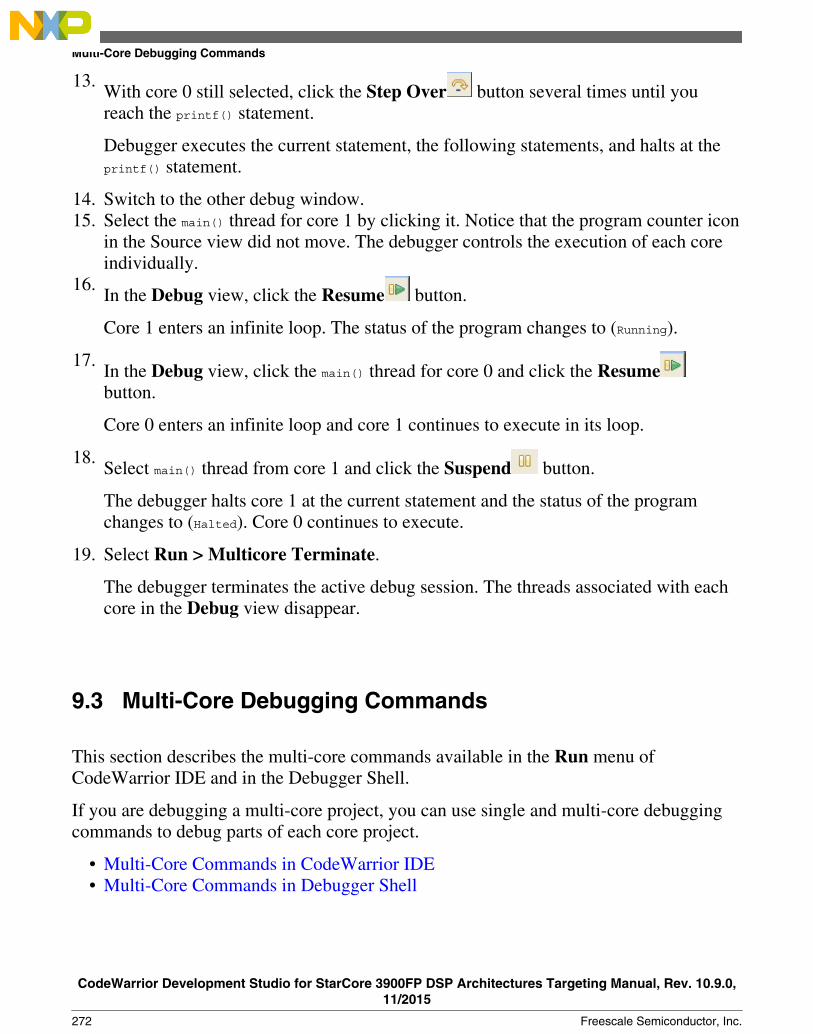
13.With core 0 still selected, click the Step Over button several times until youreach the printf() statement.
Debugger executes the current statement, the following statements, and halts at theprintf() statement.
14. Switch to the other debug window.15. Select the main() thread for core 1 by clicking it. Notice that the program counter icon
in the Source view did not move. The debugger controls the execution of each coreindividually.
16.In the Debug view, click the Resume button.
Core 1 enters an infinite loop. The status of the program changes to (Running).
17.In the Debug view, click the main() thread for core 0 and click the Resumebutton.
Core 0 enters an infinite loop and core 1 continues to execute in its loop.
18.Select main() thread from core 1 and click the Suspend button.
The debugger halts core 1 at the current statement and the status of the programchanges to (Halted). Core 0 continues to execute.
19. Select Run > Multicore Terminate.
The debugger terminates the active debug session. The threads associated with eachcore in the Debug view disappear.
9.3 Multi-Core Debugging Commands
This section describes the multi-core commands available in the Run menu ofCodeWarrior IDE and in the Debugger Shell.
If you are debugging a multi-core project, you can use single and multi-core debuggingcommands to debug parts of each core project.
• Multi-Core Commands in CodeWarrior IDE• Multi-Core Commands in Debugger Shell
Multi-Core Debugging Commands
CodeWarrior Development Studio for StarCore 3900FP DSP Architectures Targeting Manual, Rev. 10.9.0,11/2015
272 Freescale Semiconductor, Inc.

9.3.1 Multi-Core Commands in CodeWarrior IDE
This section describes the multi-core commands in the CodeWarrior IDE.
When you start a multi-core debug session, multi-core commands are enabled on theCodeWarrior IDE Run menu. These commands, when issued, affect all coressimultaneously. The table below describes each menu choice. For detailed information onthese commands, see CodeWarrior Development Studio Common Features Guide.
Table 9-2. Multi-Core Debugging Commands
Command Icon Description
Multicore Resume Starts all cores of a multi-core system running simultaneously.
Multicore Suspend Stops execution of all cores of a multi-core system simultaneously.
Multicore Restart Restarts all the debug sessions for all cores of a multi-core systemsimultaneously.
Multicore Terminate Kills all the debug sessions for all cores of a multi-core systemsimultaneously.
Multicore Groups Use All Cores: If the selected debug context is a multi-core system, thenall cores are used for multi-core operations.
Disable Halt Groups: Disables breakpoint halt groups. For moreinformation on halt groups, see "Multicore Breakpoint Halt Groups" inCodeWarrior Development Studio Common Features Guide.
Limit new breakpoints to current group: If selected, all new breakpointsset during a debug session are reproduced only on cores belonging to thegroup of the core on which the breakpoint is set.
Edit Target Types: Opens Target Types dialog box that lets you add andremove system types.
Edit Multicore Groups: Opens the Multicore Groups dialog box tocreate multi-core groups. You can also use this option to modify theexisting multi-core groups.
NOTEFor more information about creating/modifying multi-coregroups, or editing target type, see "Multicore Groups" inCodeWarrior Development Studio Common Features Guide.
To use the multi-core commands from the Debug perspective, follow these steps:
1. Start a debugging session by selecting the appropriately configured launchconfiguration.
2. If necessary, expand the desired core's list of active threads by clicking on the treecontrol in the Debug view.
3. Click the thread you want to use with multi-core operations.
Chapter 9 Multi-Core Debugging
CodeWarrior Development Studio for StarCore 3900FP DSP Architectures Targeting Manual, Rev. 10.9.0,11/2015
Freescale Semiconductor, Inc. 273

4. From the Run menu, specify the multi-core operation to perform on the thread.
NOTEThe keyboard shortcut for the Multicore Resumeoperation is Alt+Shift+F8.
9.3.2 Multi-Core Commands in Debugger Shell
This section describes the multi-core commands in debugger shell.
In addition to the multicore-specific toolbar buttons and menu commands available in theDebug view, the Debugger Shell has multi-core specific commands that can control theoperation of one or more processor cores at the same time. Like the menu commands, themulti-core debugger shell commands allow you to select, start, and stop a specific core.You can also restart or kill sessions executing on a particular core. The table below listsand defines the affect of each multi-core debugging command.
Table 9-3. Multi-Core Debugging Commands
Command Shortcut Description
mc::config mc::c List or edit multicore group options.
Syntax
mc::config
mc::go mc::g Resume multiple cores
Syntax
mc::go
Examples
mc::go
Resumes the selected cores associated with the current thread context.
mc::group mc::gr Display or edit multicore groups
Syntax
group group new <type-name> [<name>] group rename<name>|<group-index> <new-name>group remove <name>|<group-index> ... group removeall group enable|disable<index> ...|all
Examples
mc::group
Shows the defined groups, including indices for use in the mc::grouprename|enable|remove set of commands.
mc::group new 8572
Table continues on the next page...
Multi-Core Debugging Commands
CodeWarrior Development Studio for StarCore 3900FP DSP Architectures Targeting Manual, Rev. 10.9.0,11/2015
274 Freescale Semiconductor, Inc.

Table 9-3. Multi-Core Debugging Commands (continued)
Command Shortcut Description
Creates a new group for system type 8572. The group name will be basedon the system name and will be unique. The enablement of the groupelements will be all non-cores enabled, all cores disabled.
mc::group rename 0 "My Group Name"
Renames the group at index 0 to "My Group Name".
mc::group enable 0 0.0
Enables the group at index 0 and the element at index 0.0 of themc::group command.
mc::group remove "My Group Name"
Removes the group named "My Group Name".
mc::group removeall
Removes all groups.
mc::kill mc::kill Terminates the debug session for selected cores associated with thecurrent thread context.
Syntax
mc::kill
Examples
mc::kill
Terminates multiple cores.
mc::reset mc::reset Resets multiple cores.
Syntax
mc::reset
mc::restart mc::restart Restarts the debug session for selected cores associated with the currentthread context.
Syntax
mc::restart
Examples
mc::restart
Restarts multiple cores.
mc::stop mc::stop Stops the selected cores associated with the current thread context.
Syntax
mc::stop
Examples
mc::stop
Suspends multiple cores.
mc::type mc::t Shows the system types available for multicore debugging as well as typeindices for use by the mc::type remove and mc::group newcommands.
Syntax
Chapter 9 Multi-Core Debugging
CodeWarrior Development Studio for StarCore 3900FP DSP Architectures Targeting Manual, Rev. 10.9.0,11/2015
Freescale Semiconductor, Inc. 275

Table 9-3. Multi-Core Debugging Commands
Command Shortcut Description
type type import <filename> type remove <filename>|<type-index> ... type removeall
Examples
mc::type
Display or edit system types.
mc::type import 8572_jtag.txt
Creates a new type from the JTAG configuration file.
mc::type remove 8572_jtag.txt
Removes the type imported from the specified file.
mc::type removeall
Removes all imported types.
Multi-Core Debugging Commands
CodeWarrior Development Studio for StarCore 3900FP DSP Architectures Targeting Manual, Rev. 10.9.0,11/2015
276 Freescale Semiconductor, Inc.

Chapter 10Working with Hardware Tools
This chapter explains how to use the CodeWarrior hardware tools. Use these tools forboard bring-up, test, and analysis.
In this chapter:
• Flash programmer• Flash File to Target• Hardware diagnostics• Import/Export/Fill memory
10.1 Flash programmer
Flash programmer is a CodeWarrior plug-in that lets you program the flash memory ofthe supported target boards from within the IDE.
The flash programmer can program the flash memory of the target board with code froma CodeWarrior IDE project or a file. You can perform the following actions on a flashdevice using the flash programmer:
• Erase/Blank check actions• Program/Verify actions• Checksum actions• Diagnostics actions• Dump Flash actions• Protect/Unprotect actions
The flash programmer runs as a target task in the Eclipse IDE. To program the flashmemory on a target board, you need to perform the following tasks:
• Create a flash programmer target task
CodeWarrior Development Studio for StarCore 3900FP DSP Architectures Targeting Manual, Rev. 10.9.0,11/2015
Freescale Semiconductor, Inc. 277

• Configure flash programmer target task• Execute flash programmer target task
NOTEClick the Save button or press Ctrl+S to save task settings.
10.1.1 Create a flash programmer target task
You can create a flash programmer task using the Create New Target Task wizard.
1. Choose Window > Show View > Other from the CodeWarrior IDE menu bar.
The Show View dialog appears.
Figure 10-1. Show View dialog2. Expand the Debug group and select Target Tasks.3. Click OK.
The Target Tasks view appears.
Flash programmer
CodeWarrior Development Studio for StarCore 3900FP DSP Architectures Targeting Manual, Rev. 10.9.0,11/2015
278 Freescale Semiconductor, Inc.

Figure 10-2. Target Tasks view4. Click the Create a new Target Task button in the Target Tasks view toolbar.
The Create New Target Task wizard appears.
Figure 10-3. Create New Target Task window5. In the Task Name textbox, enter a name for the new flash programming target task.6. Choose a launch configuration from the Run Configuration pop-up menu.
• Choose Active Debug Context when flash programmer is used over an activedebug session.
• Choose a project-specific debug context when flash programmer is used withoutan active debug session.
7. Choose Flash Programmer from the Task Type pop-up menu.
Chapter 10 Working with Hardware Tools
CodeWarrior Development Studio for StarCore 3900FP DSP Architectures Targeting Manual, Rev. 10.9.0,11/2015
Freescale Semiconductor, Inc. 279

8. Click Finish.
The target task is created and the Flash Programmer Task editor window appears.You use this window to configure the flash programmer target task.
• Flash Devices - Lists the devices added in the current task.• Target RAM - Lets you specify the settings for Target RAM.• Flash Program Actions - Displays the programmer actions to be performed on
the flash devices.
10.1.2 Configure flash programmer target task
You can add flash devices, specify Target RAM settings, and add flash program actionsto a flash programmer task to configure it.
This topic contains the following sub-topics:
• Add flash device• Specify target RAM settings• Add flash programmer actions
10.1.2.1 Add flash device
To add a flash device to the Flash Devices table:
1. Click the Add Device button.
The Add Device dialog appears.
2. Select a flash device from the device list.3. Click the Add Device button.
The flash device is added to the Flash Devices table in the Flash Programmer Taskeditor window.
NOTEYou can select multiple flash devices to add to the FlashDevices table. To select multiple devices, hold down theControl key while selecting the devices.
4. Click Done.
Flash programmer
CodeWarrior Development Studio for StarCore 3900FP DSP Architectures Targeting Manual, Rev. 10.9.0,11/2015
280 Freescale Semiconductor, Inc.
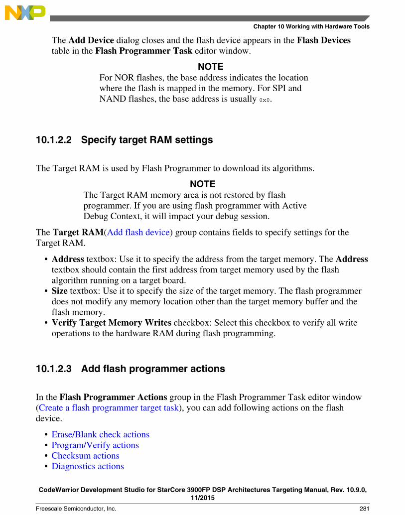
The Add Device dialog closes and the flash device appears in the Flash Devicestable in the Flash Programmer Task editor window.
NOTEFor NOR flashes, the base address indicates the locationwhere the flash is mapped in the memory. For SPI andNAND flashes, the base address is usually 0x0.
10.1.2.2 Specify target RAM settings
The Target RAM is used by Flash Programmer to download its algorithms.
NOTEThe Target RAM memory area is not restored by flashprogrammer. If you are using flash programmer with ActiveDebug Context, it will impact your debug session.
The Target RAM(Add flash device) group contains fields to specify settings for theTarget RAM.
• Address textbox: Use it to specify the address from the target memory. The Addresstextbox should contain the first address from target memory used by the flashalgorithm running on a target board.
• Size textbox: Use it to specify the size of the target memory. The flash programmerdoes not modify any memory location other than the target memory buffer and theflash memory.
• Verify Target Memory Writes checkbox: Select this checkbox to verify all writeoperations to the hardware RAM during flash programming.
10.1.2.3 Add flash programmer actions
In the Flash Programmer Actions group in the Flash Programmer Task editor window(Create a flash programmer target task), you can add following actions on the flashdevice.
• Erase/Blank check actions• Program/Verify actions• Checksum actions• Diagnostics actions
Chapter 10 Working with Hardware Tools
CodeWarrior Development Studio for StarCore 3900FP DSP Architectures Targeting Manual, Rev. 10.9.0,11/2015
Freescale Semiconductor, Inc. 281
• Dump Flash actions• Protect/Unprotect actions
The Flash Programmer Actions group contains the following UI controls to work withflash programmer actions:
• Add Action pop-up menu• Erase/Blank Check Action: Allows you to add erase or blank check actions for
a flash device.• Program/Verify Action: Allows you to add program or verify flash actions for a
flash device.• Checksum Action: Allows you to add checksum actions for a flash device.• Diagnostics Action: Lets you add a diagnostics action.• Dump Flash Action: Lets you add a dump flash action.• Protect/Unprotect Action: Lets you add protect or unprotect action.• Secure/Unsecure Action: Lets you add secure or unsecure action.
• Duplicate Action button: Allows you to duplicate a flash program action in theFlash Programmer Actions table.
• Remove Action button: Allows you to remove a flash program action from the FlashProgrammer Actions table.
• Move Upbutton: Allows you to move up the selected flash action in the FlashProgrammer Actions table.
• Move Down button: Allows you to move down the selected flash action in the FlashProgrammer Actions table.
NOTEActions can also be enabled or disabled using the Enabledcolumn. The Description column contains the defaultdescription for the flash programmer actions. You can also editthe default description.
10.1.2.3.1 Erase/Blank check actions
The Erase action erases sectors from the flash device.
You can also use the erase action to erase the entire flash memory without selectingsectors. The blank check action verifies if the specified areas have been erased from theflash device.
NOTEFlash Programmer will not erase a bad sector in the NANDflash. After the erase action a list of bad sectors is reported (ifany).
Flash programmer
CodeWarrior Development Studio for StarCore 3900FP DSP Architectures Targeting Manual, Rev. 10.9.0,11/2015
282 Freescale Semiconductor, Inc.

To add an erase/blank check action:
1. Choose Erase/Blank Check Action from the Add Action pop-up menu.
The Add Erase/Blank Check Action dialog appears.
2. Select a sector from the Sectors table and click the Add Erase Action button to addan erase operation on the selected sector.
NOTEPress the Control or the Shift key for selecting multiplesectors from the Sectors table.
3. Click the Add Blank Check button to add a blank check operation on the selectedsector.
4. Select the Erase All Sectors Using Chip Erase Command checkbox to erase theentire flash memory.
NOTEAfter selecting the Erase All Sectors Using Chip EraseCommand checkbox, you need to add either erase or blankcheck action to erase all sectors.
5. Click Done.
The Add Erase/Blank Check Action dialog closes and the added erase/blank checkactions appear in the Flash Programmer Actions table in the Flash ProgrammerTask editor window.
10.1.2.3.2 Program/Verify actions
The Program action allows you to program the flash device and the verify action verifiesthe programmed flash device.
NOTEThe program action will abort and fail if it is performed in a badblock for NAND flashes.
To add a program/verify action:
1. Choose Program/Verify Action from the Add Action pop-up menu.
The Add Program/Verify Action dialog appears.
2. Select the file to be written to the flash device.
Chapter 10 Working with Hardware Tools
CodeWarrior Development Studio for StarCore 3900FP DSP Architectures Targeting Manual, Rev. 10.9.0,11/2015
Freescale Semiconductor, Inc. 283

3. Select the Use File from Launch Configuration checkbox to use the file from thelaunch (run) configuration associated with the task.
4. Specify the file name in the File textbox. You can use Workspace, File System, orVariables buttons to select the desired file.
5. Choose a file type from the File Type pop-up menu. You can select any one of thefollowing file types:
• Auto - Detects the file type automatically.• Elf - Specifies executable in ELF format.• Srec - Specifies files in Motorola S-record format.• Binary - Specifies binary files.
6. Select the Erase sectors before program checkbox to erase sectors before program.7. [Optional] Select the Verify after program checkbox to verify after the program.
NOTEThe Verify after program checkbox is available only withthe processors supporting it.
8. Select the Restricted To Address in this Range checkbox to specify a memoryrange. The write action is permitted only in the specified address range. In the Starttextbox, specify the start address of the memory range sector and in the End textbox,specify the end address of the memory range.
9. Select the Apply Address Offset checkbox and set the memory address in theAddress textbox. Value is added to the start address of the file to be programmed orverified.
10. Click the Add Program Action button to add a program action on the flash device.11. Click the Add Verify Action button to add a verify action on the flash device.12. Click Done.
The Add Program/Verify Action dialog closes and the added program/verifyactions appear in the Flash Programmer Actions table in the Flash ProgrammerTask editor window.
10.1.2.3.3 Checksum actions
The checksum can be computed over host file, target file, memory range or entire flashmemory.
To add a checksum action:
1. Choose Checksum Action from the Add Action pop-up menu.
The Add Checksum Action dialog appears.
Flash programmer
CodeWarrior Development Studio for StarCore 3900FP DSP Architectures Targeting Manual, Rev. 10.9.0,11/2015
284 Freescale Semiconductor, Inc.

2. Select the file for checksum action.3. Select the Use File from Launch Configuration checkbox to use the file from the
launch (run) configuration associated with the task.4. Specify the filename in the File textbox. You can use the Workspace, File System,
or Variables buttons to select the desired file.5. Choose the file type from the File Type pop-up menu.6. Select an option from the Compute Checksum Over options. The checksum can be
computed over the host file, the target file, the memory range, or the entire flashmemory.
7. Specify the memory range in the Restricted To Addresses in this Range group. Thechecksum action is permitted only in the specified address range. In the Starttextbox, specify the start address of the memory range sector and in the End textbox,specify the end address of the memory range.
8. Select the Apply Address Offset checkbox and set the memory address in theAddress textbox. Value is added to the start address of the file to be programmed orverified.
9. Click the Add Checksum Action button.10. Click Done.
The Add Checksum Action dialog closes and the added checksum actions appear inthe Flash Programmer Actions table in the Flash Programmer Task editorwindow.
10.1.2.3.4 Diagnostics actions
The diagnostics action generates the diagnostic information for a selected flash device.
NOTEFlash Programmer will report bad blocks, if they are present inthe NAND flash.
To add a diagnostics action:
1. Choose Diagnostics from the Add Action pop-up menu.
The Add Diagnostics Action dialog appears.
2. Select a device to perform the diagnostics action.3. Click the Add Diagnostics Action button to add diagnostic action on the selected
flash device.
Chapter 10 Working with Hardware Tools
CodeWarrior Development Studio for StarCore 3900FP DSP Architectures Targeting Manual, Rev. 10.9.0,11/2015
Freescale Semiconductor, Inc. 285

NOTESelect the Perform Full Diagnostics checkbox to performfull diagnostics on a flash device.
4. Click Done.
The Add Diagnostics Action dialog closes and the added diagnostics action appearsin the Flash Programmer Actions table in the Flash Programmer Task editorwindow.
10.1.2.3.5 Dump Flash actions
The dump flash action allows you to dump selected sectors of a flash device or the entireflash device.
To add a dump flash action:
1. Choose Dump Flash Action from the Add Action pop-up menu.
The Add Dump Flash Action dialog appears.
2. Specify the file name in the File textbox. The flash is dumped in this selected file.3. Choose the file type from the File Type pop-up menu. You can choose any one of
the following file types:• Srec: Saves files in Motorola S-record format.• Binary: Saves files in binary file format.
4. Specify the memory range for which you want to add dump flash action.• Enter the start address of the range in the Start textbox.• Enter the end address of the range in the End textbox.
5. Click the Add Dump Flash Action button to add a dump flash action.6. Click Done.
The Add Dump Flash Action dialog closes and the added dump flash action appearin the Flash Programmer Actions table in the Flash Programmer Task editorwindow.
10.1.2.3.6 Protect/Unprotect actions
The protect/unprotect actions allow you to change the protection of a sector in the flashdevice.
To add a protect/unprotect action:
Flash programmer
CodeWarrior Development Studio for StarCore 3900FP DSP Architectures Targeting Manual, Rev. 10.9.0,11/2015
286 Freescale Semiconductor, Inc.
1. Choose the Protect/Unprotect Action from the Add Action pop-up menu.
The Add Protect/Unprotect Action dialog appears.
2. Select a sector from the Sectors table and click the Add Protect Action button toadd a protect operation on the selected sector.
NOTEPress the Control or Shift key for selecting multiple sectorsfrom the Sectors table.
3. Click the Add Unprotect Action button to add an unprotect action on the selectedsector.
4. Select the All Device checkbox to add action on full device.5. Click Done.
The Add Protect/Unprotect Action dialog closes and the added protect or unprotectactions appear in the Flash Programmer Actions table in the Flash ProgrammerTask editor window.
10.1.2.3.7 Duplicate action
You can duplicate a flash programmer action from the Flash Programmer Actionstable.
1. Select the action in the Flash Programmer Actions table.2. Click the Duplicate Action button.
The selected action is copied in the Flash Programmer Action table.
10.1.2.3.8 Remove action
You can remove a flash programmer action from the Flash Programmer Actions table.
1. Select the action in the Flash Programmer Actions table.2. Click the Remove Action button.
The selected action is removed from the Flash Programmer Action table.
Chapter 10 Working with Hardware Tools
CodeWarrior Development Studio for StarCore 3900FP DSP Architectures Targeting Manual, Rev. 10.9.0,11/2015
Freescale Semiconductor, Inc. 287
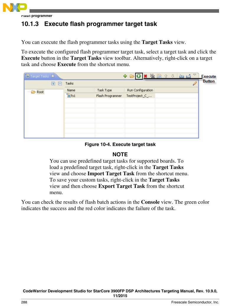
10.1.3 Execute flash programmer target task
You can execute the flash programmer tasks using the Target Tasks view.
To execute the configured flash programmer target task, select a target task and click theExecute button in the Target Tasks view toolbar. Alternatively, right-click on a targettask and choose Execute from the shortcut menu.
Figure 10-4. Execute target task
NOTEYou can use predefined target tasks for supported boards. Toload a predefined target task, right-click in the Target Tasksview and choose Import Target Task from the shortcut menu.To save your custom tasks, right-click in the Target Tasksview and then choose Export Target Task from the shortcutmenu.
You can check the results of flash batch actions in the Console view. The green colorindicates the success and the red color indicates the failure of the task.
Flash programmer
CodeWarrior Development Studio for StarCore 3900FP DSP Architectures Targeting Manual, Rev. 10.9.0,11/2015
288 Freescale Semiconductor, Inc.

Figure 10-5. Console view
10.1.4 Flash Programmer Use Case
This topic lists the following use case:
• Using Flash Programmer to Write uboot Image to Target
10.1.4.1 Using Flash Programmer to Write uboot Image to Target
You need to perform the following actions to write uboot images using CodeWarrior forStarCore 3900FP DSP flash programmer:
NOTEYou need B4860QDS_NOR_FLASH.xml for RCW writing at step 5, andthe offset at step 7 is 0xE8000000.
1. Edit the launch configuration.
NOTECodeWarrior for StarCore 3900FP DSP flash programmersupports both SRAM and DDR init files. For this tutorial,you must change the default init file with the SRAM init forcore 0.
To edit the launch config, perform these steps:
Chapter 10 Working with Hardware Tools
CodeWarrior Development Studio for StarCore 3900FP DSP Architectures Targeting Manual, Rev. 10.9.0,11/2015
Freescale Semiconductor, Inc. 289

a. Select Run > Debug Configurations to open the Debug configurations dialogbox.
b. Select Core 0 launch configc. From the Target settings group, click Edit.
The Properties for <connection> dialog box appears.
d. From the Target option, click Edit.
The Properties for <connection> Target dialog box appears.
e. Check the Target Initialize checkbox for core 0, then click in the Initializetarget script column.
f. Click the browse button (...) to open the Target Initialization File dialog box.g. Click File System and select B4860_QDS_SRAM_Init.tcl file from SC
\StarCore_Support\Initialization_Files\RegisterConfigFiles\B4860_QDSfolder.
Figure 10-6. Target Initialization File Dialog Box2. Start a debugging session. Wait until the control stops at address 0x00000000.3. Press Ctrl + 3 and write Commander to open the Commander view.4. From Commander view, click Flash programmer.5. From the Flash Configuration File group click Browse and select
B4860QDS_NOR_FLASH.xml to write u-boot in NOR memory, otherwise use the NAND file.6. Click Browse to specify for your u-boot image file in the File textbox.7. Write your u-boot offset in Offset textbox. You may use 0xeff80000.8. You can save the file by selecting Save as Target Task option, otherwise, clear the
checkbox.9. Click Erase and Program.
Flash programmer
CodeWarrior Development Studio for StarCore 3900FP DSP Architectures Targeting Manual, Rev. 10.9.0,11/2015
290 Freescale Semiconductor, Inc.

Figure 10-7. Flash File To Target Dialog Box
The flash programmer writes the uboot image file to the target.
NOTEIf you cannot connect to the board anymore, you can write thenew RCW by following these steps:
1. Note and save the current configuration of SW2 and SW3.2. Modify the switches to boot from hard-coded RCW:
a. SW3 -> 0100_0011b. SW2 -> 0111_0100c. SW2: SRC8 (b1) set to 0 and RES_REQ(b5) set to 0.
3. Connect to the board and write the new RCW using theinstructions listed above.
4. Set the switches back to the saved configuration.
10.2 Flash File to Target
You can use the Flash File to Target feature to perform flash operations such as erasinga flash device or programming a file.
Chapter 10 Working with Hardware Tools
CodeWarrior Development Studio for StarCore 3900FP DSP Architectures Targeting Manual, Rev. 10.9.0,11/2015
Freescale Semiconductor, Inc. 291
You do not need any project for using Flash File to Target feature, only a valid RemoteSystem is required.
To open the Flash File to Target dialog, click the Flash Programmer button on the IDEtoolbar.
• Connection pop-up menu- Lists all run configurations defined in Eclipse. If aconnection to the target has already been made the control becomes inactive andcontains the text Active Debug Configuration.
• Flash Configuration File pop-up menu - Lists predefined target tasks for theprocessor selected in the Launch Configuration and tasks added by user with theBrowse button. The items in this pop-up menu are updated based on the processorselected in the launch configuration. For more information on launch configurations,see product's Targeting Manual.
• Unprotect flash memory before erase checkbox - Select to unprotect flashmemory before erasing the flash device. This feature allows you to unprotect theflash memory from Flash File To Target dialog.
• File to Flash group - Allows selecting the file to be programmed on the flash deviceand the location.
• File textbox - Used for specifying the filename. You can use the Workspace,File System, or Variables buttons to select the desired file.
• Offset:0x textbox - Used for specifying offset location for a file. If no offset isspecified the default value of zero is used. The offset is always added to the startaddress of the file. If the file does not contain address information then zero isconsidered as start address.
• Save as Target Task - Select to enable Task Name textbox.• Task Name textbox - Lets you to save the specified settings as a Flash target
task. Use the testbox to specify the name of the target task.• Erase Whole Device button - Erases the flash device. In case you have multiple
flash blocks on the device, all blocks are erased. If you want to selectively erase orprogram blocks, use the Flash programmer feature.
• Erase and Program button - Erases the sectors that are occupied with data and thenprograms the file. If the flash device can not be accessed at sector level then the flashdevice is completely erased.
This feature helps you perform these basic flash operations:
• Erasing flash device• Programming a file
Flash File to Target
CodeWarrior Development Studio for StarCore 3900FP DSP Architectures Targeting Manual, Rev. 10.9.0,11/2015
292 Freescale Semiconductor, Inc.

10.2.1 Erasing flash device
To erase a flash device, follow these steps:
1. Click the Flash Programmer button on the IDE toolbar.
The Flash File to Target dialog appears.
2. Choose a connection from the Connection pop-up menu.
NOTEIf a connection is already established with the target, thiscontrol is disabled.
The Flash Configuration File pop-up menu is updated with the supportedconfigurations for the processor from the launch configuration.
3. Choose a flash configuration from the Flash Configuration File pop-up menu.4. Select the Unprotect flash memory before erase checkbox to unprotect flash
memory before erasing the flash device.5. Click the Erase Whole Device button.
10.2.2 Programming a file
1. Click the Flash Programmer button on the IDE toolbar.
The Flash File to Target dialog appears.
2. Choose a connection from the Connection pop-up menu.
NOTEIf a connection is already established with the target, thiscontrol is disabled.
The Flash Configuration File pop-up menu is updated with the supportedconfigurations for the processor from the launch configuration.
3. Choose a flash configuration from the Flash Configuration File pop-up menu.4. Select the Unprotect flash memory before erase checkbox to unprotect flash
memory before erasing the flash device.5. Type the file name in the File textbox. You can use the Workspace, File System, or
Variables buttons to select the desired file.6. Type the offset location in the Offset textbox.7. Click the Erase and Program button.
Chapter 10 Working with Hardware Tools
CodeWarrior Development Studio for StarCore 3900FP DSP Architectures Targeting Manual, Rev. 10.9.0,11/2015
Freescale Semiconductor, Inc. 293

10.3 Hardware diagnostics
The Hardware Diagnostics utility lets you run a series of diagnostic tests that determineif the basic hardware is functional.
These tests include:
• Memory read/write: This test only makes a read or write access to the memory toread or write a byte, word (2 bytes) and long word (4 bytes) to or from the memory.For this task, the user needs to set the options in the Memory Access group.
• Scope loop: This test makes read and write accesses to memory in a loop at the targetaddress. The time between accesses is given by the loop speed settings. The loop canonly be stopped by the user, which cancels the test. For this type of test, the userneeds to set the memory access settings and the loop speed.
• Memory tests: This test requires the user to set the access size and target addressfrom the access settings group and the settings present in the Memory Tests group.
This topic contains the following sub-topics:
• Creating hardware diagnostics task• Working with Hardware Diagnostic Action editor• Memory test use cases
10.3.1 Creating hardware diagnostics task
You can create a hardware diagnostic task using the Create New Target Task wizard.
To create a task for hardware diagnostics:
1. Choose Window > Show View > Other from the IDE menu bar.
The Show View dialog appears.
2. Expand the Debug group and select Target Tasks.3. Click OK.4. Click the Create a new Target Task button on the Target Tasks view toolbar.
Alternatively, right-click in the Target Tasks view and choose New Task from theshortcut menu.
The Create a New Target Task wizard appears.
Hardware diagnostics
CodeWarrior Development Studio for StarCore 3900FP DSP Architectures Targeting Manual, Rev. 10.9.0,11/2015
294 Freescale Semiconductor, Inc.

5. Type name for the new task in the Task Name textbox.6. Choose a launch configuration from the Run Configuration pop-up menu.
NOTEIf the task does not successfully launch the configurationthat you specify, the Execute button on the Target Tasksview toolbar stays unavailable.
7. Choose Hardware Diagnostic from the Task Type pop-up menu.8. Click Finish.
A new hardware diagnostic task is created in the Target Tasks view.
NOTEYou can perform various actions on a hardware diagnostictask, such as renaming, deleting, or executing the task,using the shortcut menu that appears on right-clicking thetask in the Target tasks view.
10.3.2 Working with Hardware Diagnostic Action editor
The Hardware Diagnostic Action editor is used to configure a hardware diagnostic task.
To open the Hardware Diagnostic Action editor for a particular task, double-click thetask in the Target Tasks view.
The following figure shows the Hardware Diagnostics Action editor.
Chapter 10 Working with Hardware Tools
CodeWarrior Development Studio for StarCore 3900FP DSP Architectures Targeting Manual, Rev. 10.9.0,11/2015
Freescale Semiconductor, Inc. 295

Figure 10-8. Hardware Diagnostics Action editor
The Hardware Diagnostics Action editor window includes the following groups:
• Action Type• Memory Access• Loop Speed• Memory Tests
10.3.2.1 Action Type
The Action Type group in the Hardware Diagnostics Action editor window is used forselecting the action type.
You can choose any one of the following actions:
• Memory read/write - Enables the options in the Memory Access group.
Hardware diagnostics
CodeWarrior Development Studio for StarCore 3900FP DSP Architectures Targeting Manual, Rev. 10.9.0,11/2015
296 Freescale Semiconductor, Inc.

• Scope loop - Enables the options in the Memory Access and the Loop Speedgroups.
• Memory test - Enables the access size and target address from the access settingsgroup and the settings present in the Memory Tests group.
10.3.2.2 Memory Access
The Memory Access pane configures diagnostic tests for performing memory reads andwrites over the remote connection interface.
The table below lists and describes the items in the pane.
Table 10-1. Memory Access Pane Items
Item Description
Read Select to have the hardware diagnostic tools perform read tests.
Write Select to have the hardware diagnostic tools perform write tests.
1 unit Select to have the hardware diagnostic tools perform one memory unit access size operations.
2 units Select to have the hardware diagnostic tools perform two memory units access size operations.
4 units Select to have the hardware diagnostic tools perform four memory units access size operations.
Target Address Specify the address of an area in RAM that the hardware diagnostic tools should analyze. Thetools must be able to access this starting address through the remote connection (after thehardware initializes).
Value Specify the value that the hardware diagnostic tools write during testing. Select the Write optionto enable this textbox.
Verify Memory Writes Select the checkbox to verify success of each data write to the memory.
10.3.2.3 Loop Speed
The Loop Speed pane configures diagnostic tests for performing repeated memory readsand writes over the remote connection interface.
The tests repeat until you stop them. By performing repeated read and write operations,you can use a scope analyzer or logic analyzer to debug the hardware device. After thefirst 1000 operations, the Status shows the estimated time between operations.
NOTEFor all values of Speed, the time between operations dependsheavily on the processing speed of the host computer.
Chapter 10 Working with Hardware Tools
CodeWarrior Development Studio for StarCore 3900FP DSP Architectures Targeting Manual, Rev. 10.9.0,11/2015
Freescale Semiconductor, Inc. 297

For Read operations, the Scope Loop test has an additional feature. During the first readoperation, the hardware diagnostic tools store the value read from the hardware. For allsuccessive read operations, the hardware diagnostic tools compare the read value to thestored value from the first read operation. If the Scope Loop test determines that the valueread from the hardware is not stable, the diagnostic tools report the number of times thatthe read value differs from the first read value. Following table lists and describes theitems in Loop Speed pane.
Table 10-2. Loop Speed Pane Items
Item Description
Set Loop Speed Enter a numeric value between 0 to 1000 in the textbox to adjust the speed. You canalso move the slider to adjust the speed at which the hardware diagnostic tools repeatsuccessive read and write operations. Lower speeds increase the delay betweensuccessive operations. Higher speeds decrease the delay between successiveoperations.
10.3.2.4 Memory Tests
The Memory Tests pane lets you perform three hardware tests, Walking Ones, BusNoise, and Address.
You can specify any combination of tests and number of passes to perform. For eachpass, the hardware diagnostic tools performs the tests in turn, until all passes arecomplete. The tools compare memory test failures and display them in a log window afterall passes are complete. Errors resulting from memory test failures do not stop the testingprocess; however, fatal errors immediately stop the testing process.
The following table explains the items in the Memory Tests pane.
Table 10-3. Memory Tests pane items
Item Explanation
Walking 1's Select the checkbox to have the hardware diagnostic tools perform the Walking Ones test.Deselect to have the diagnostic tools skip the Walking Ones test.
Address Select to have the hardware diagnostic tools perform the Address test. Deselect to have thediagnostic tools skip the Address test.
Bus Noise Select to have the hardware diagnostic tools perform the Bus noise test. Deselect to have thediagnostic tools skip the Bus noise test.
Test Area Size Specify the size of memory to be tested. This setting along with Target Address defines thememory range being tested.
Number of Passes Enter the number of times that you want to repeat the specified tests.
Table continues on the next page...
Hardware diagnostics
CodeWarrior Development Studio for StarCore 3900FP DSP Architectures Targeting Manual, Rev. 10.9.0,11/2015
298 Freescale Semiconductor, Inc.

Table 10-3. Memory Tests pane items (continued)
Item Explanation
Use Target CPU Select to have the hardware diagnostic tools download the test code to the hardware device.Deselect to have the hardware diagnostic tools execute the test code through the remoteconnection interface. Execution performance improves greatly if you execute the test code onthe hardware CPU, but requires that the hardware has enough stability and robustness toexecute the test code.
NOTE: The option is not applicable for CodeWarrior StarCore devices.
Download Algorithm toAddress
Specify the address where the test driver is downloaded in case the Use target CPU isselected.
NOTE: The option is not applicable for CodeWarrior StarCore devices.
10.3.2.4.1 Walking Ones
This test detects these memory faults:
• Address Line: The board or chip address lines are shorting or stuck at 0 or 1. Eithercondition could result in errors when the hardware reads and writes to the memorylocation. Because this error occurs on an address line, the data may end up in thewrong location on a write operation, or the hardware may access the wrong data on aread operation.
• Data Line: The board or chip data lines are shorting or stuck at 0 or 1. Eithercondition could result in corrupted values as the hardware transfers data to or frommemory.
• Retention: The contents of a memory location change over time. The effect is that thememory fails to retain its contents over time.
The Walking Ones test includes four sub-tests:
• Walking Ones: This subtest first initializes memory to all zeros. Then the subtestwrites, reads, and verifies bits, with each bit successively set from the leastsignificant bit ( LSB) to the most significant bit ( MSB). The subtest configures bitssuch that by the time it sets the MSB, all bits are set to a value of 1. This patternrepeats for each location within the memory range that you specify. For example, thevalues for a byte-based Walking Ones subtest occur in this order:
0x01, 0x03, 0x07, 0x0F, 0x1F, 0x3F, 0x7F, 0xFF
• Ones Retention: This subtest immediately follows the Walking Ones subtest. TheWalking Ones subtest should leave each memory location with all bits set to 1. TheOnes Retention subtest verifies that each location has all bits set to 1.
• Walking Zeros: This subtest first initializes memory to all ones. Then the subtestwrites, reads, and verifies bits, with each bit successively set from the LSB to the
Chapter 10 Working with Hardware Tools
CodeWarrior Development Studio for StarCore 3900FP DSP Architectures Targeting Manual, Rev. 10.9.0,11/2015
Freescale Semiconductor, Inc. 299

MSB. The subtest configures bits such that by the time it sets the MSB, all bits areset to a value of 0. This pattern repeats for each location within the memory rangethat you specify. For example, the values for a byte-based Walking Zeros subtestoccur in this order:
0xFE, 0xFC, 0xF8, 0xF0, 0xE0, 0xC0, 0x80, 0x00
• Zeros Retention: This subtest immediately follows the Walking Zeros subtest. TheWalking Zeros subtest should leave each memory location with all bits set to 0. TheZeros Retention subtest verifies that each location has all bits set to 0.
10.3.2.4.2 Address
This test detects memory aliasing. Memory aliasing exists when a physical memory blockrepeats one or more times in a logical memory space. Without knowing about thiscondition, you might conclude that there is much more physical memory than whatactually exists.
The address test uses a simplistic technique to detect memory aliasing. The test writessequentially increasing data values (starting at one and increasing by one) to eachsuccessive memory location. The maximum data value is a prime number and its specificvalue depends on the addressing mode so as to not overflow the memory location.
The test uses a prime number of elements to avoid coinciding with binary mathboundaries:
• For byte mode, the maximum prime number is 28-5 or 251.• For word mode, the maximum prime number is 216-15 or 65521.• For long word mode, the maximum prime number is 232-5 or 4294967291.
If the test reaches the maximum value, the value rolls over to 1 and starts incrementingagain. This sequential pattern repeats throughout the memory under test. Then the testreads back the resulting memory and verifies it against the written patterns. Anydeviation from the written order could indicate a memory aliasing condition.
10.3.2.4.3 Bus noise
This test stresses the memory system by causing many bits to flip from one memoryaccess to the next (both addresses and data values). Bus noise occurs when many bitschange consecutively from one memory access to another. This condition can occur onboth address and data lines.
Hardware diagnostics
CodeWarrior Development Studio for StarCore 3900FP DSP Architectures Targeting Manual, Rev. 10.9.0,11/2015
300 Freescale Semiconductor, Inc.

10.3.2.4.4 Address lines
To force bit flips in address lines, the test uses three approaches:
• Sequential- This approach works sequentially through all of the memory under test,from lowest address to highest address. This sequential approach results in anaverage number of bit flips from one access to the next.
• Full Range Converging- This approach works from the fringes of the memory rangetoward the middle of the memory range. Memory access proceeds in this pattern,where + number and - number indicate the next item location (the specificincrement or decrement depends on byte, word, or long word address mode):
• the lowest address• the highest address• (the lowest address) + 1• (the highest address) - 1• (the lowest address) + 2• (the highest address) - 2
• Maximum Invert Convergence- This approach uses calculated end point addresses tomaximize the number of bits flipping from one access to the next. This approachinvolves identifying address end points such that the values have the maximuminverted bits relative to one another. Specifically, the test identifies the lowestaddress with all 0x5 values in the least significant nibbles and the highest addresswith all 0xA values in the least significant nibbles. After the test identifies these endpoints, memory access alternates between low address and high address, workingtowards the center of the memory under test. Accessing memory in this manner, thetest achieves the maximum number of bits flips from one access to the next.
10.3.2.4.5 Data lines
To force bit flips in data lines, the test uses two sets of static data, a pseudo-random setand a fixed-pattern set. Each set contains 31 elements-a prime number. The test uses aprime number of elements to avoid coinciding with binary math boundaries. The sets areunique to each addressing mode so as to occupy the full range of bits.
• The test uses the pseudo-random data set to stress the data lines in a repeatable butpattern-less fashion.
• The test uses the fixed-pattern set to force significant numbers of data bits to flipfrom one access to the next.
Chapter 10 Working with Hardware Tools
CodeWarrior Development Studio for StarCore 3900FP DSP Architectures Targeting Manual, Rev. 10.9.0,11/2015
Freescale Semiconductor, Inc. 301

The sub-tests execute similarly in that each subtest iterates through static data, writingvalues to memory. The test combines the three address line approaches with the two datasets to produce six unique sub-tests:
• Sequential with Random Data• Sequential with Fixed Pattern Data• Full Range Converging with Random Data• Full Range Converging with Fixed Pattern Data• Maximum Invert Convergence with Random Data• Maximum Invert Convergence with Fixed Pattern Data
10.3.3 Memory test use cases
The memory read /write and scope loop tests are host based tests. The host machineissues read and write action to the memory through the connection protocol. For exampleCCS.
Memory tests are the complex tests that can be executed in two modes: Host based andTarget based
depending upon the selection made for the Use Target CPU checkbox.
• Selected: Target Based• Deselected: Host Based
The Host Based tests are slower than the Target Based tests.
10.3.3.1 Use Case 1: Execute host-based Scope Loop on target
You need to perform the following action to execute the host based scope loop on thetarget:
1. Select Scope loop in the Action Type.2. Set Memory Access settings from the Memory Access section.3. Set the speed used for the scope loop diagnostic from the Loop Speed section.4. Save the settings.5. Press Execute to execute the action.
Hardware diagnostics
CodeWarrior Development Studio for StarCore 3900FP DSP Architectures Targeting Manual, Rev. 10.9.0,11/2015
302 Freescale Semiconductor, Inc.

10.3.3.2 Use Case 2: Execute target-based Memory Tests on target
You need to perform the following action to execute the target based memory test on thetarget:
1. Select Memory Test in the Action Type.2. Specify Target Address and Access Size settings from the Memory Access section.3. Specify the following settings for Memory Tests section:
• Test Area Size: The tested memory region is computed from Target Addressuntil Target Address + Test Area Size.
• Tests to Run: Select tests to run on the target.• Number of passes: Specify number of times a test will be executed.• Use Target CPU: set the Address to which the test driver (algorithm) is to be
downloaded.4. Save the settings.5. Press Execute to execute the action.
10.4 Import/Export/Fill memory
The Import/Export/Fill Memory utility lets you export memory contents to a file andimport data from a file into memory.
The utility also supports filling memory with a user provided data pattern.
10.4.1 Creating task for import/export/fill memory
You can use the Import/Export/Fill Memory utility to perform various tasks onmemory.
The utility can be accessed from the Target Tasks view.
To open the Target Tasks view:
1. Choose Window > Show View > Other from the IDE menu bar.
The Show View dialog appears.
2. Expand the Debug group.3. Select Target Tasks.
Chapter 10 Working with Hardware Tools
CodeWarrior Development Studio for StarCore 3900FP DSP Architectures Targeting Manual, Rev. 10.9.0,11/2015
Freescale Semiconductor, Inc. 303
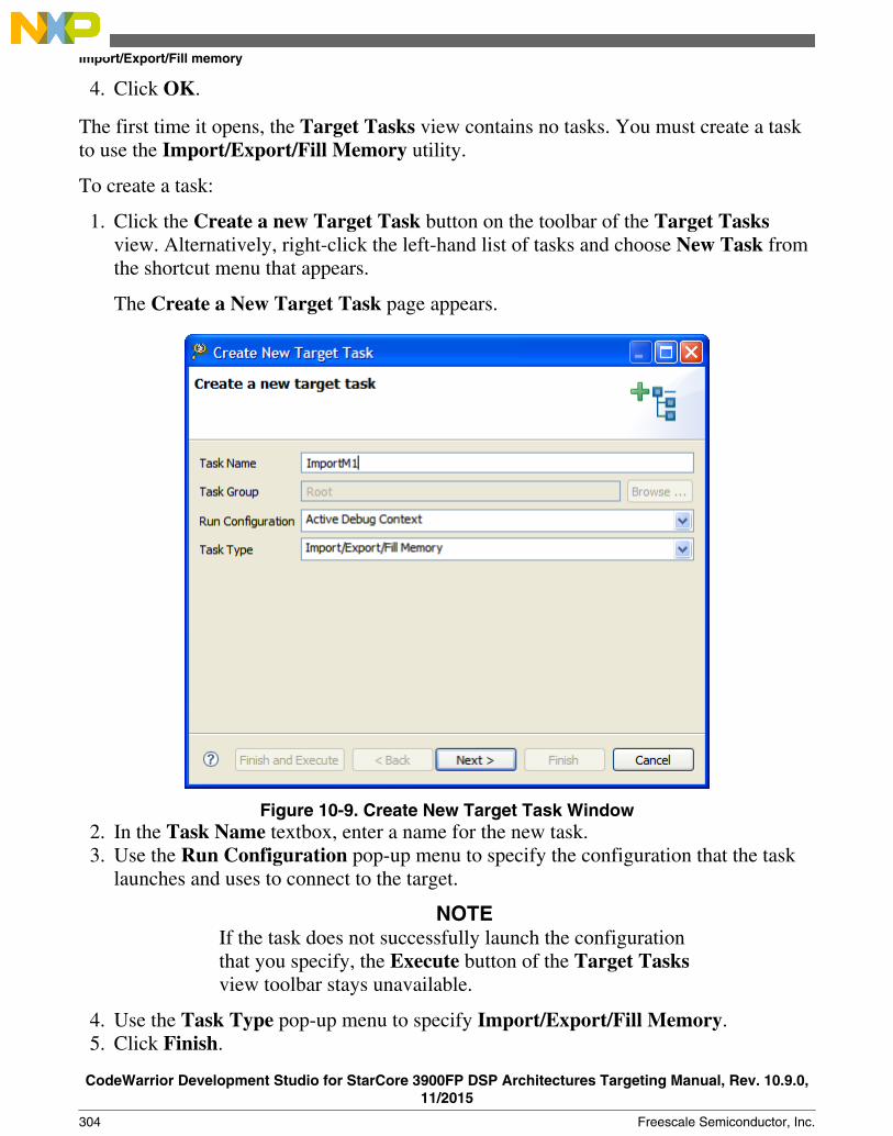
4. Click OK.
The first time it opens, the Target Tasks view contains no tasks. You must create a taskto use the Import/Export/Fill Memory utility.
To create a task:
1. Click the Create a new Target Task button on the toolbar of the Target Tasksview. Alternatively, right-click the left-hand list of tasks and choose New Task fromthe shortcut menu that appears.
The Create a New Target Task page appears.
Figure 10-9. Create New Target Task Window2. In the Task Name textbox, enter a name for the new task.3. Use the Run Configuration pop-up menu to specify the configuration that the task
launches and uses to connect to the target.
NOTEIf the task does not successfully launch the configurationthat you specify, the Execute button of the Target Tasksview toolbar stays unavailable.
4. Use the Task Type pop-up menu to specify Import/Export/Fill Memory.5. Click Finish.
Import/Export/Fill memory
CodeWarrior Development Studio for StarCore 3900FP DSP Architectures Targeting Manual, Rev. 10.9.0,11/2015
304 Freescale Semiconductor, Inc.

The Import/Export/Fill Memory target task is created and it appears in the Import/Export/Fill Memory Action editor.
Figure 10-10. Import/Export Memory Action editor
10.4.2 Importing data into memory
You can import the encoded data from a user specified file, decode it, and copy it into auser specified memory range.
Select the Import memory option from the Import/Export/Fill Memory Action editorto import data into memory.
Chapter 10 Working with Hardware Tools
CodeWarrior Development Studio for StarCore 3900FP DSP Architectures Targeting Manual, Rev. 10.9.0,11/2015
Freescale Semiconductor, Inc. 305

Figure 10-11. Import/Export Memory Action editor - Importing data into memory
The following table explains the import memory options.
Table 10-4. Controls used for importing data into memory
Item Explanation
Memory space and address Enter the literal address and memory space on which the data transfer is performed.The Literal address field allows only decimal and hexadecimal values.
Expression Enter the memory address or expression at which the data transfer starts.
Access Size Denotes the number of addressable units of memory that the debugger accesses intransferring one data element. The default values shown are 1, 2, and 4 units. Whentarget information is available, this list shall be filtered to display the access sizes thatare supported by the target.
Select file Enter the path to the file that contains the data to be imported. Click the Workspacebutton to select a file from the current project workspace. Click the System button toselect a file from the file system the standard File Open dialog. Click the Variablesbutton to select a build variable.
File Type Defines the format in which the imported data is encoded. By default, the following filetypes are supported:
• Signed decimal Text• Unsigned decimal Text• Motorola S-Record format• Hex Text
Table continues on the next page...
Import/Export/Fill memory
CodeWarrior Development Studio for StarCore 3900FP DSP Architectures Targeting Manual, Rev. 10.9.0,11/2015
306 Freescale Semiconductor, Inc.

Table 10-4. Controls used for importing data into memory (continued)
Item Explanation
• Annotated Hex Text• Raw Binary
Number of Elements Enter the total number of elements to be transferred.
Verify Memory Writes Select the checkbox to verify success of each data write to the memory.
10.4.3 Exporting memory to file
You can read data from a user specified memory range, encode it in a user specifiedformat, and store this encoded data in a user specified output file.
Select the Export memory option from the Import/Export/Fill Memory Action editorto export memory to a file.
Figure 10-12. Exporting memory
Chapter 10 Working with Hardware Tools
CodeWarrior Development Studio for StarCore 3900FP DSP Architectures Targeting Manual, Rev. 10.9.0,11/2015
Freescale Semiconductor, Inc. 307

The following table explains the export memory options.
Table 10-5. Controls used for exporting data from memory into file
Item Explanation
Memory space and address Enter the literal address and memory space on which the data transfer is performed.The Literal address field allows only decimal and hexadecimal values.
Expression Enter the memory address or expression at which the data transfer starts.
Access Size Denotes the number of addressable units of memory that the debugger accesses intransferring one data element. The default values shown are 1, 2, and 4 units. Whentarget information is available, this list shall be filtered to display the access sizes thatare supported by the target.
Select file Enter the path of the file to write data. Click the Workspace button to select a file fromthe current project workspace. Click the System button to select a file from the filesystem the standard File Open dialog. Click the Variables button to select a buildvariable.
File Type Defines the format in which encoded data is exported. By default, the following filetypes are supported:
• Signed decimal Text• Unsigned decimal Text• Motorola S-Record format• Hex Text• Annotated Hex Text• Raw Binary
Number of Elements Enter the total number of elements to be transferred.
10.4.4 Fill memory
You can fill a user specified memory range with a user specified data pattern.
Select the Fill memory option from the Import/Export/Fill Memory Action editorwindow to fill memory.
Import/Export/Fill memory
CodeWarrior Development Studio for StarCore 3900FP DSP Architectures Targeting Manual, Rev. 10.9.0,11/2015
308 Freescale Semiconductor, Inc.
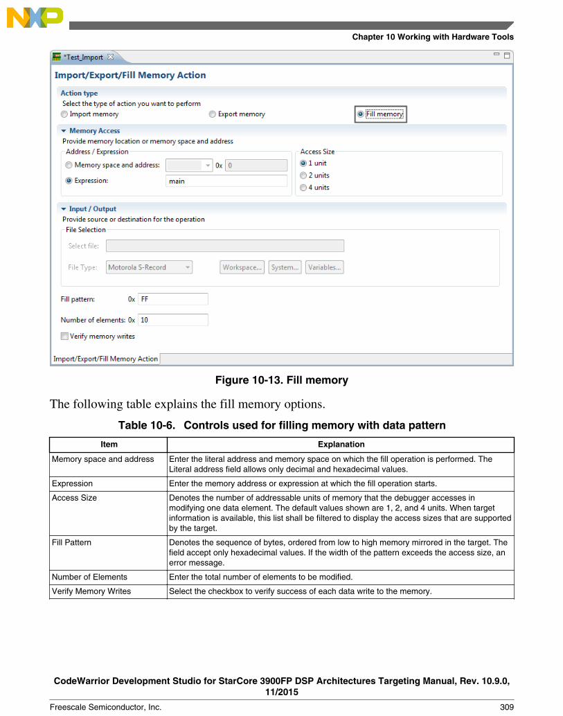
Figure 10-13. Fill memory
The following table explains the fill memory options.
Table 10-6. Controls used for filling memory with data pattern
Item Explanation
Memory space and address Enter the literal address and memory space on which the fill operation is performed. TheLiteral address field allows only decimal and hexadecimal values.
Expression Enter the memory address or expression at which the fill operation starts.
Access Size Denotes the number of addressable units of memory that the debugger accesses inmodifying one data element. The default values shown are 1, 2, and 4 units. When targetinformation is available, this list shall be filtered to display the access sizes that are supportedby the target.
Fill Pattern Denotes the sequence of bytes, ordered from low to high memory mirrored in the target. Thefield accept only hexadecimal values. If the width of the pattern exceeds the access size, anerror message.
Number of Elements Enter the total number of elements to be modified.
Verify Memory Writes Select the checkbox to verify success of each data write to the memory.
Chapter 10 Working with Hardware Tools
CodeWarrior Development Studio for StarCore 3900FP DSP Architectures Targeting Manual, Rev. 10.9.0,11/2015
Freescale Semiconductor, Inc. 309

Import/Export/Fill memory
CodeWarrior Development Studio for StarCore 3900FP DSP Architectures Targeting Manual, Rev. 10.9.0,11/2015
310 Freescale Semiconductor, Inc.

Chapter 11Exception Configurator
This chapter explains how to use the CodeWarrior Exception Configurator tool.
Use the Exceptions Configurator view to quickly determine the cause of an exceptionwhile executing an application.
To view the details of an exception using the Exceptions Configurator view, followthese steps:
1. Switch the IDE to the Debug perspective and start a debugging session.2. Select Window > Show View > Other.
The Show View dialog box appears (Figure 11-1).
Figure 11-1. Show View Dialog Box3. Expand the Debug group.4. Select Exceptions Configurator.5. Click OK.
CodeWarrior Development Studio for StarCore 3900FP DSP Architectures Targeting Manual, Rev. 10.9.0,11/2015
Freescale Semiconductor, Inc. 311

The Exception Configurator view appears (Figure 11-2).
NOTEA blank window appears if no process is selected from thedebug window.
Figure 11-2. Exceptions Configurator View6. Check the Catch checkbox to select the exception.
Checking a parent node will automatically check all the children nodes. Clearing aparent node checkbox clears all the children nodes.
7. If you wish to change the current value of the VBA register, enter a hexadecimalvalue, a symbol name or a register name in the Vector Base Address text box.
NOTEThe debugger will try to evaluate the expression providedin the Vector Base Address text box. If the evaluation fails,specified text will be highlighted in red.
8. Click the Apply Changes button ( ) to save the changes.
The exceptions configurator is configured to capture the selected exceptions.
9. Retry the steps that caused the exception.
The debugger displays a complete stack crawl. The exceptions captured by theExceptions Configurator view are highlighted in red (Figure 11-3).
Figure 11-3. Exceptions
CodeWarrior Development Studio for StarCore 3900FP DSP Architectures Targeting Manual, Rev. 10.9.0,11/2015
312 Freescale Semiconductor, Inc.

NOTEException settings defined for each debug configurationmay not be identical. The state of the captured exceptions ispersistent after restart.
Chapter 11 Exception Configurator
CodeWarrior Development Studio for StarCore 3900FP DSP Architectures Targeting Manual, Rev. 10.9.0,11/2015
Freescale Semiconductor, Inc. 313

CodeWarrior Development Studio for StarCore 3900FP DSP Architectures Targeting Manual, Rev. 10.9.0,11/2015
314 Freescale Semiconductor, Inc.

Chapter 12Memory Management Unit Configurator
This chapter explains how to use the CodeWarrior Memory Management Unit (MMU)Configurator. The MMU allows different user tasks or programs (usually in the contextof an RTOS) to use the same areas of memory. To use the MMU:
• You set up a mapping for data and instruction addresses• Enable address translation
The mapping links the virtual addresses to the physical addresses. Translation occursbefore software acts on the addresses.
The MMU Configurator simplifies peripheral-register initialization of the MMUregisters. You can use the tool to generate code that you can insert into a program. Theinserted code initializes an MMU configuration or writes to the registers on-the-fly. Also,you can use the MMU Configurator to examine the status of the current MMUconfiguration.
Use the MMU Configurator to:
• Configure MMU general control registers• Configure MMU program memory-address-translation properties• Configure MMU data memory-address-translation properties• Display the current contents of each register• Write the displayed contents from the MMU Configurator to the MMU registers• Save to a file (in a format that you specify) the displayed contents of the MMU
Configurator
This chapter has these sections:
• Creating MMU Configuration• MMU Configuration File Editor Pages• MMU Editor Menu• MMU Editor Toolbar
CodeWarrior Development Studio for StarCore 3900FP DSP Architectures Targeting Manual, Rev. 10.9.0,11/2015
Freescale Semiconductor, Inc. 315

• Saving MMU Configuration• MMU Configurator View
12.1 Creating MMU Configuration
In order to use the MMU Configurator, you need to create an MMU configuration.
Follow these steps to create the configuration:
1. From the CodeWarrior IDE menu bar, select File > New > Other.
The New wizard starts, displaying its Select a wizard page.
2. Expand the Peripheral Configurators tree control and select MMU ConfigurationFile (Figure 12-1).
Figure 12-1. Select a wizard Page of New Wizard3. Click Next.
The New wizard closes and the MMU Configurator Wizard starts, displaying itsMMU Configurator File page.
4. In the Container text box, type the path of the directory where you want to store theMMU configuration, or click Browse to find and select the new file container.
Creating MMU Configuration
CodeWarrior Development Studio for StarCore 3900FP DSP Architectures Targeting Manual, Rev. 10.9.0,11/2015
316 Freescale Semiconductor, Inc.

5. In the File name text box, type the name of the MMU configuration, or leave thedefault name intact.
NOTEIf you enter a new name, ensure to preserve the .mmu fileextension.
6. Expand a tree control in the Device Number group.7. From the expanded list, select the target hardware for which you want to create the
MMU configuration. For example, B4860 ( Figure 12-2).
Figure 12-2. MMU Configurator File Page of MMU Configurator Wizard
NOTEWhen started in the offline mode, the MMU Configuratorfills in the required defaults for all fields.
8. Click Finish.
Chapter 12 Memory Management Unit Configurator
CodeWarrior Development Studio for StarCore 3900FP DSP Architectures Targeting Manual, Rev. 10.9.0,11/2015
Freescale Semiconductor, Inc. 317

The MMU Configurator Wizard closes. CodeWarrior IDE generates the MMUconfiguration file in the specified container directory and opens the MMUConfiguration File Editor.
12.2 MMU Configuration File Editor Pages
This section explains each page of the MMU Configuration File Editor.
You use these pages to configure MMU mapping and translation properties. The tabbedinterface of the MMU Configuration File Editor displays pages for configuration optionsand for the generated code.
NOTEWhen you specify settings in the MMU Configuration FileEditor, configure the tabbed pages in left-to-right order. Forexample, configure the General page before configuring theTranslations page. In addition, within a page, configure settingsfrom the top-left position to the bottom-right position.
Table 12-1 lists the MMU Configuration File Editor pages.
Table 12-1. MMU Configuration File Editor Pages
Page Description
General This page helps you configure the overall MMU configurations (as opposedto specific properties for each virtual-to-physical map entry).
Translations This page helps you configure the program and data translations (virtual-to-physical address mappings) for the StarCore 3900FP DSP.
new_file.mmu This page displays the generated MMU state file. MMU Configuratorgenerates the state file each time you change the MMU configuration.
12.2.1 General
Use this page to configure the overall MMU configurations (as opposed to specificproperties for each virtual-to-physical map entry).
Figure 12-3 shows the General page of the MMU Configuration File Editor.
MMU Configuration File Editor Pages
CodeWarrior Development Studio for StarCore 3900FP DSP Architectures Targeting Manual, Rev. 10.9.0,11/2015
318 Freescale Semiconductor, Inc.

Figure 12-3. MMU Configuration File Editor - General Page
NOTEIf you check the Voluntary Cache Commands Cancelcheckbox, the MMU cancels the cache command for programand data except for DFLUSH and DSYNC. Similarly, if youcheck the Voluntary Cache Commands Error checkbox, theMMU indicates the core for DFETCH/DFL2C*/DMALLOC/PFETCH/PFL2C* address errors.
Table 12-2 explains the options available on the General page of the MMU ConfigurationFile Editor.
Table 12-2. MMU Configuration File Editor - General Page Settings
Option Description
Address Translation Checked - Enables address translation. For example, translation occurs froma virtual address to a physical address.
Cleared - Disables address translation. For example, translation does notoccur from a virtual address to a physical address.
This option corresponds to the Address Translation Enable (ATE) bit of theMMU Control Register (M_CR).
Memory Protection Checked - Enables memory protection checking for all enabled segmentdescriptors. With this option checked, the system consumes more power.
Table continues on the next page...
Chapter 12 Memory Management Unit Configurator
CodeWarrior Development Studio for StarCore 3900FP DSP Architectures Targeting Manual, Rev. 10.9.0,11/2015
Freescale Semiconductor, Inc. 319

Table 12-2. MMU Configuration File Editor - General Page Settings (continued)
Option Description
Cleared - Disables memory protection checking for all enabled segmentdescriptors. This option corresponds to the Memory Protection Enable(MPE) bit of the MMU Control Register (M_CR).
Gather Enable Checked - Enables the gather option.
Cleared - Disables the gather option.
Instruction Cache Enable Checked - Enables the cache in instruction mode.
Cleared - Disables the cache instruction mode.
Data Cache Enable Checked - Enables the data cache mode.
Cleared - Disables the data cache mode.
Stack Overrun Error Checked - Throws error for stack overrun.
Cleared - Does not throw error for stack overrun.
Error Detection Code Exception Checked - Enables the error detection mode for code exceptions.
Cleared - Disables the error detection mode for code exceptions.
Voluntary Cache Commands Cancel Checked - Cancels the voluntary cache commands.
Cleared - Does not cancel the voluntary cache commands.
Voluntary Cache Commands Error Checked - Enables the voluntary cache commands error mode.
Cleared - Disables the voluntary cache commands error.
12.2.2 Translations
Use the Translations page to define and display program and data translations (virtual-to-physical address mappings) for the StarCore 3900FP DSPs.
The MMU Configuration File Editor generates the appropriate descriptors for theprogram and data Memory-Address Translation Table (MATT).
On the Translations page, details of program and/or data translations are shown in theMATT table on the left side and settings of the entry, currently selected in the MATTtable, are summarized on the right side. By clicking the header of a column in the MATTtable, you can sort the table data based on that column. Modified translations in theMATT table display in blue color. Similarly, erroneous translations display in red color.
To modify a translation, follow these steps:
1. Select an option from the Select Translations drop-down list within the Type group.Based on the option selected in the Select Translations drop-down list, the MATTtable displays details of program and/or data translations.
MMU Configuration File Editor Pages
CodeWarrior Development Studio for StarCore 3900FP DSP Architectures Targeting Manual, Rev. 10.9.0,11/2015
320 Freescale Semiconductor, Inc.

2. Select a translation from the MATT table. The options displayed in the Propertiesgroup vary depending on the type of translation selected in the MATT table.
3. Change the Address, Size, and Properties group settings.
Figure 12-4 shows the Translations page of the MMU Configuration File Editor when aprogram translation is selected in the MATT table.
Figure 12-4. MMU Configuration File Editor - Translations Page for a ProgramTranslation
Figure 12-5 shows the Translations page of the MMU Configuration File Editor when adata translation is selected in the MATT table.
Chapter 12 Memory Management Unit Configurator
CodeWarrior Development Studio for StarCore 3900FP DSP Architectures Targeting Manual, Rev. 10.9.0,11/2015
Freescale Semiconductor, Inc. 321
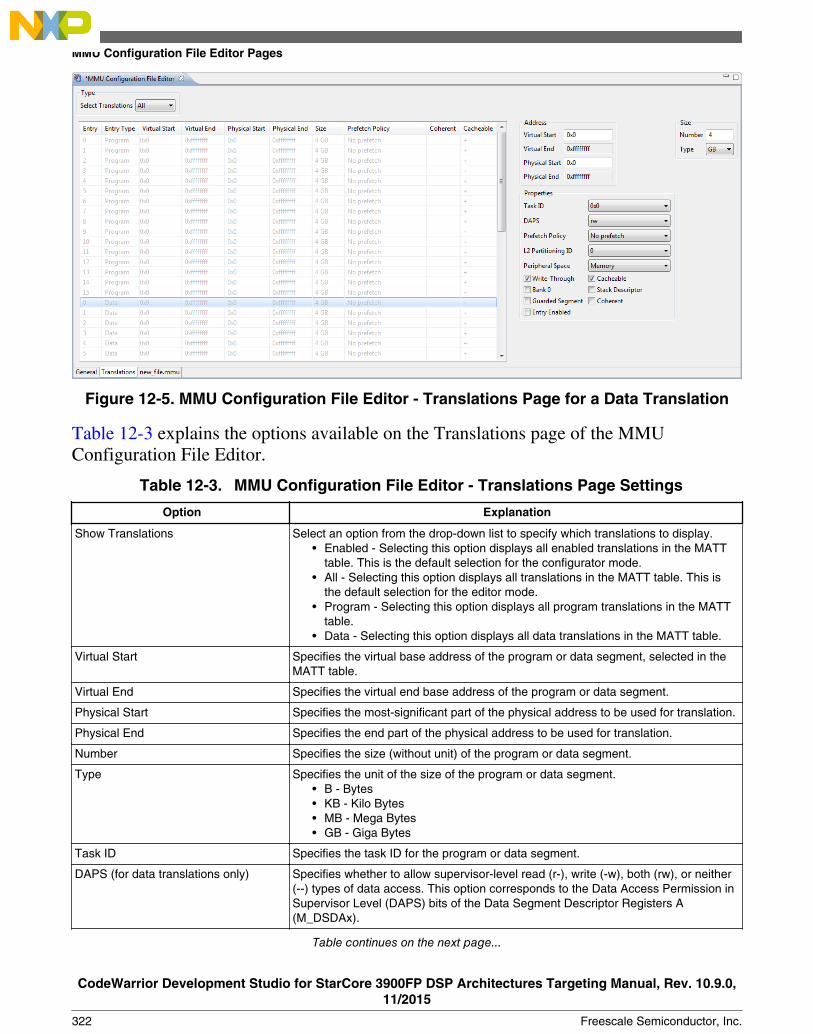
Figure 12-5. MMU Configuration File Editor - Translations Page for a Data Translation
Table 12-3 explains the options available on the Translations page of the MMUConfiguration File Editor.
Table 12-3. MMU Configuration File Editor - Translations Page Settings
Option Explanation
Show Translations Select an option from the drop-down list to specify which translations to display.• Enabled - Selecting this option displays all enabled translations in the MATT
table. This is the default selection for the configurator mode.• All - Selecting this option displays all translations in the MATT table. This is
the default selection for the editor mode.• Program - Selecting this option displays all program translations in the MATT
table.• Data - Selecting this option displays all data translations in the MATT table.
Virtual Start Specifies the virtual base address of the program or data segment, selected in theMATT table.
Virtual End Specifies the virtual end base address of the program or data segment.
Physical Start Specifies the most-significant part of the physical address to be used for translation.
Physical End Specifies the end part of the physical address to be used for translation.
Number Specifies the size (without unit) of the program or data segment.
Type Specifies the unit of the size of the program or data segment.• B - Bytes• KB - Kilo Bytes• MB - Mega Bytes• GB - Giga Bytes
Task ID Specifies the task ID for the program or data segment.
DAPS (for data translations only) Specifies whether to allow supervisor-level read (r-), write (-w), both (rw), or neither(--) types of data access. This option corresponds to the Data Access Permission inSupervisor Level (DAPS) bits of the Data Segment Descriptor Registers A(M_DSDAx).
Table continues on the next page...
MMU Configuration File Editor Pages
CodeWarrior Development Studio for StarCore 3900FP DSP Architectures Targeting Manual, Rev. 10.9.0,11/2015
322 Freescale Semiconductor, Inc.

Table 12-3. MMU Configuration File Editor - Translations Page Settings (continued)
Option Explanation
Prefetch Policy Specifies the prefetch policy for the program or data segment:• No Prefetch• Prefetch on miss access• Prefetch on any access• Reserved
L2 Partitioning ID Specifies the L2 partitioning ID for the program or data segment.
Peripheral Space (for data translationsonly)
Specifies the peripheral space for the data segment:• Memory• Peripheral
Write-Through (for data translationsonly)
Checked - MMU enables the write through option.
Cleared - MMU disables the write through option.
Cacheable Checked - Enables caching of the segment in the instruction cache.
Cleared - Disables caching of the segment in the instruction cache.
PAPS (for program translations only) Checked - Segment has supervisor-level fetch permission for program accesses. Ifyou check the PAPU option, you disable program-protection checks for thissegment.
Cleared - Segment does not have supervisor-level fetch permission for programaccesses.
This option corresponds to the Program Access Permission in Supervisor Level(PAPS) bit of the Program Segment Descriptor Registers A (M_PSDAx).
Bank 0 (for data translations only) Checked - MMU enables the bank 0 option.
Cleared - MMU disables the bank 0 option.
Stack Descriptor (for data translationsonly)
Checked - MMU enables the stack descriptor.
Cleared - MMU disables the stack descriptor.
Guarded Segment (for data translationsonly)
Checked - MMU enables the guarded segment option.
Cleared - MMU disables the guarded segment option.
Entry Enabled Checked - MMU enables this translation entry.
Cleared - MMU disables this translation entry.
Coherent Checked - MMU enables the coherent entry.
Cleared - MMU disables the coherent entry.
12.2.3 new_file.mmu
The new_file.mmu page contains the generated MMU state file.
The MMU Configuration File Editor generates the state file each time you change theMMU configuration. The state file contains target-specific register-state information, aswell as Family and Target Device Number state data that you specified in the wizard youused to create the configuration.
Chapter 12 Memory Management Unit Configurator
CodeWarrior Development Studio for StarCore 3900FP DSP Architectures Targeting Manual, Rev. 10.9.0,11/2015
Freescale Semiconductor, Inc. 323

The MMU Configurator uses the state file to re initialize the settings on each page. Youcan maintain a collection of state files and load the file that initializes settings for aparticular set of translations.
Figure 12-6 shows the new_file.mmu page of the MMU Configuration File Editor.
Figure 12-6. MMU Configuration File Editor - < filename>.mmu Page
NOTEThe MMU Configuration File Editor regenerates thenew_file.mmu page when you change settings in the MMUConfiguration File Editor pages.
12.3 MMU Editor Menu
The MMU Configuration File Editor has an associated menu, MMU Editor, that displaysin the CodeWarrior IDE menu bar, when MMU Configuration File Editor is active in theEditor view.
Table 12-4 explains each menu item in the MMU Editor menu.
Table 12-4. MMU Editor Menu Items
Menu Item Icon Description
Save C Saves the generated C code to anew .c file.
Save ASM Saves the generated assembly code to anew .asm file.
Table continues on the next page...
MMU Editor Menu
CodeWarrior Development Studio for StarCore 3900FP DSP Architectures Targeting Manual, Rev. 10.9.0,11/2015
324 Freescale Semiconductor, Inc.

Table 12-4. MMU Editor Menu Items (continued)
Menu Item Icon Description
Save TCL Saves the generated TCL script to anew .tcl file.
Read Target Registers Updates the content of the MMUConfiguration File Editor pages to reflectthe current values of the target hardwareregisters.
Write Target Registers Writes the modified content of the MMUConfiguration File Editor pages to thetarget hardware registers.
12.4 MMU Editor Toolbar
The MMU Configuration File Editor has an associated toolbar that displays in theCodeWarrior IDE toolbar, when MMU Configuration File Editor is active in the Editorview.
Table 12-5 explains each toolbar button.
Table 12-5. MMU Editor Toolbar Buttons
Toolbar Button Icon Description
Save C Source Saves the generated C code to a new .c file.
Save ASM Source Saves the generated assembly code to a new .asmfile.
Save TCL Source Saves the generated TCL script to a new .tcl file.
Load MMU Configurator state from activethread
Updates the content of the MMU Configuration FileEditor pages to reflect the current values of thetarget hardware registers.
Write active thread registers from MMUConfigurator state
Writes the modified content of the MMUConfiguration File Editor pages to the targethardware registers.
12.5 Saving MMU Configuration
This section explains how to save the changes you made in the MMU Configurator.
Chapter 12 Memory Management Unit Configurator
CodeWarrior Development Studio for StarCore 3900FP DSP Architectures Targeting Manual, Rev. 10.9.0,11/2015
Freescale Semiconductor, Inc. 325
Each time you change the settings in the MMU Configurator File Editor, you create apending or unsaved change. In order to commit those pending changes, you need to savethe MMU Configurator settings to a file. If an asterisk (*) appears before the title of theMMU Configuration File Editor, it implies that the editor still has unsaved changes.
• Saving MMU Configuration File Editor Settings• Saving Generated C Code• Saving Generated Assembly Code• Saving Generated TCL Script
12.5.1 Saving MMU Configuration File Editor Settings
Follow these steps to save the current settings of the MMU Configuration File Editor:
1. Select the MMU Configuration File Editor.2. From the CodeWarrior IDE menu bar, select File > Save.
The IDE saves the current settings of the MMU Configuration File Editor to the .mmufile.
12.5.2 Saving Generated C Code
The generated C code is unique for each target. Follow these steps to save the C codegenerated by the MMU Configuration File Editor:
1. From the CodeWarrior IDE menu bar, select MMU Editor > Save C to save thegenerated C code. Alternatively, click the Save C Source button in the MMU editortoolbar.
A standard Save dialog box appears.
2. Specify the file name in the File name text box and click Save to save the generatedcode as a new file.
NOTEThe MMU Configuration File Editor regenerates the C codewhen you change settings in the MMU Configuration FileEditor pages.
Saving MMU Configuration
CodeWarrior Development Studio for StarCore 3900FP DSP Architectures Targeting Manual, Rev. 10.9.0,11/2015
326 Freescale Semiconductor, Inc.
12.5.3 Saving Generated Assembly Code
The generated assembly (ASM) code is unique for each target. Follow these steps to savethe ASM code generated by the MMU Configuration File Editor:
1. From the CodeWarrior IDE menu bar, select MMU Editor > Save ASM to save thegenerated assembly code. Alternatively, click the Save ASM Source button in theMMU editor toolbar.
A standard Save dialog box appears.
2. Specify the file name in the File name text box and click Save to save the generatedcode as a new file.
NOTEThe MMU Configuration File Editor regenerates the assemblycode when you change settings in the MMU Configuration FileEditor pages.
12.5.4 Saving Generated TCL Script
The generated TCL script can be executed within the Debugger Shell view, or theDebugger Shell can execute the generated TCL script as an initialization script for thetarget hardware. The generated TCL script is unique for each target.
Follow these steps to save the TCL script generated by the MMU Configuration FileEditor:
1. From the CodeWarrior IDE menu bar, select MMU Editor > Save TCL to save thegenerated TCL script. Alternatively, click the Save TCL Source button in the MMUeditor toolbar.
A standard Save dialog box appears.
2. Specify the file name in the File name text box and click Save to save the generatedcode as a new file.
Chapter 12 Memory Management Unit Configurator
CodeWarrior Development Studio for StarCore 3900FP DSP Architectures Targeting Manual, Rev. 10.9.0,11/2015
Freescale Semiconductor, Inc. 327
NOTEThe MMU Configuration File Editor regenerates the TCLscript when you change settings in the MMU ConfigurationFile Editor pages.
12.6 MMU Configurator View
Use the MMU Configurator view to examine the current state of a thread's MMUconfiguration during the debug session.
You can also detach the MMU Configurator view into its own floating window andreposition the window within the collection of views.
To open the MMU Configurator view, follow these steps:
1. Start a debugging session.2. In the Debug view of the Debug perspective, select the process for which you want
to work with MMU.3. Select Window > Show View > Other.
The Show View dialog box appears.
4. Expand the Debug tree control.5. Select MMU Configurator (Figure 12-7).
MMU Configurator View
CodeWarrior Development Studio for StarCore 3900FP DSP Architectures Targeting Manual, Rev. 10.9.0,11/2015
328 Freescale Semiconductor, Inc.

Figure 12-7. Show View Dialog Box - MMU Configurator6. Click OK.
The Show View dialog box closes. The MMU Configurator view appears, attachedto an existing collection of views in the current perspective.
Chapter 12 Memory Management Unit Configurator
CodeWarrior Development Studio for StarCore 3900FP DSP Architectures Targeting Manual, Rev. 10.9.0,11/2015
Freescale Semiconductor, Inc. 329

MMU Configurator View
CodeWarrior Development Studio for StarCore 3900FP DSP Architectures Targeting Manual, Rev. 10.9.0,11/2015
330 Freescale Semiconductor, Inc.
Chapter 13Maple Memory Management Unit Configurator
This chapter explains how to use the Maple Memory Management Unit (MMU)Configurator. To use the Maple MMU:
• You set up a mapping for data addresses• Enable address translation
The mapping links the virtual addresses to the physical addresses. Translation occursbefore software acts on the addresses.
The Maple MMU Configurator simplifies peripheral-register initialization of the MapleMMU registers. You can use the Maple MMU Configurator to examine the status of thecurrent Maple MMU configuration.
Use the Maple MMU Configurator to:
• Configure Maple MMU general control registers• Configure Maple MMU memory-address-translation properties• Display the current contents of each register• Write the displayed contents from the Maple MMU Configurator to the Maple MMU
registers
This chapter has these sections:
• Maple MMU Configurator View• Maple MMU Configurator View Pages• Maple MMU Configurator View Menu
13.1 Maple MMU Configurator View
Use the Maple MMU Configurator view to examine the current state of a thread'sMaple MMU configuration during the debug session.
CodeWarrior Development Studio for StarCore 3900FP DSP Architectures Targeting Manual, Rev. 10.9.0,11/2015
Freescale Semiconductor, Inc. 331

You can also detach the Maple MMU Configurator view into its own floating windowand reposition the window within the collection of views.
To open the Maple MMU Configurator view, follow these steps:
1. Start a debugging session.2. In the Debug view of the Debug perspective, select the process for which you want
to work with Maple MMU.3. Select Window > Show View > Other.
The Show View dialog box appears.
4. Expand the Debug tree control.5. Select Maple MMU Configurator (as the following figure shows).
Figure 13-1. Show View Dialog Box - Maple MMU Configurator6. Click OK.
The Show View dialog box closes. The Maple MMU Configurator view appears,attached to an existing collection of views in the current perspective.
13.2 Maple MMU Configurator View Pages
This section explains each page of the Maple MMU Configurator view.
Maple MMU Configurator View Pages
CodeWarrior Development Studio for StarCore 3900FP DSP Architectures Targeting Manual, Rev. 10.9.0,11/2015
332 Freescale Semiconductor, Inc.

You use these pages to configure Maple MMU mapping and translation properties. Thetabbed interface of the Maple MMU Configurator view displays pages for theconfiguration options.
NOTEWhen you specify settings in the Maple MMU Configuratorview, configure the tabbed pages in left-to-right order. Forexample, configure the General page before configuring theTranslations page. In addition, within a page, configuresettings from the top-left position to the bottom-right position.
The following table lists the Maple MMU Configurator pages.
Table 13-1. Maple MMU Configurator Pages
Page Description
General This page helps you configure the overall Maple MMU configurations (asopposed to specific properties for each virtual-to-physical map entry).
Translations This page helps you configure the data translations (virtual-to-physicaladdress mappings) for maple instances.
13.2.1 General
Use this page to configure the overall Maple MMU configurations (as opposed to specificproperties for each virtual-to-physical map entry).
The following figure shows the General page of the Maple MMU Configurator.
Figure 13-2. Maple MMU Configurator - General Page
Chapter 13 Maple Memory Management Unit Configurator
CodeWarrior Development Studio for StarCore 3900FP DSP Architectures Targeting Manual, Rev. 10.9.0,11/2015
Freescale Semiconductor, Inc. 333

The following table describes the options available on the General page of the MapleMMU Configurator.
Table 13-2. Maple MMU Configurator - General Page Settings
Option Description
Select Maple Instance Use this option to select Lte0, Lte1 and wcdma mapleinstances.
NOTE: The availability of the options depends on the targetselected.
• LTE1 is not supported for b4420.• LTE0, LTE1 and WCDMA are supported for
B4060, B4460 and B4860.• Maple instances are not supported for G4860
and SC3900 targets.
Address Translation Checked - Enables address translation. For example,translation occurs from a virtual address to a physicaladdress.
Cleared - Disables address translation. For example,translation does not occur from a virtual address to a physicaladdress.
This option corresponds to the Address Translation Enable(ATE) bit of the register from the list below, depending on theMaple instance you selected:
• MAPLE_B3LW0_M_CR• MAPLE_B3LW1_M_CR• MAPLE_B3W_M_CR
Memory Protection Checked - Enables memory protection checking for allenabled segment descriptors. With this option checked, thesystem consumes more power.
Cleared - Disables memory protection checking for allenabled segment descriptors.
This option corresponds to the Memory Protection Enable(MPE) bit of the register from the list below, depending on theMaple instance you selected:
• MAPLE_B3LW0_M_CR• MAPLE_B3LW1_M_CR• MAPLE_B3W_M_CR
Violation Monitor Displays current violation status.
Clear Violation Use this button to clear the violation data.
13.2.2 Translations
Use the Translations page to define and display data translations (virtual-to-physicaladdress mappings) for the maple instances.
Maple MMU Configurator View Pages
CodeWarrior Development Studio for StarCore 3900FP DSP Architectures Targeting Manual, Rev. 10.9.0,11/2015
334 Freescale Semiconductor, Inc.

The Maple MMU Configurator generates the appropriate descriptors for the dataMemory-Address Translation Table (MATT).
On the Translations page, details of the data translations are shown in the MATT tableon the left side and settings of the entry, currently selected in the MATT table, aresummarized on the right side. By clicking the header of a column in the MATT table, youcan sort the table data based on that column. Modified translations in the MATT tabledisplay in blue color. Similarly, erroneous translations display in red color.
To modify a translation, follow these steps:
1. Select an option from the Select Translations drop-down list within the Type group.Based on the option selected in the Select Translations drop-down list, the MATTtable displays details of data translations.
2. Select a translation from the MATT table.3. Change the Address, Size, and Properties group settings.
The following figure shows the Translations page of the Maple MMU Configurator.
Figure 13-3. Maple MMU Configurator - Translations Page
The following table describes the options available on the Translations page of the MapleMMU Configurator.
Table 13-3. MMU Configuration File Editor - Translations Page Settings
Option Explanation
Select Translations Select an option from the drop-down list to specify which translations to display.• Enabled - Selecting this option displays all enabled translations in the MATT
table. This is the default selection for the configurator mode.• All - Selecting this option displays all translations in the MATT table.
Virtual Start Specifies the virtual base address of the data segment, selected in the MATT table.
Virtual End Specifies the virtual end base address of the data segment.
Physical Start Specifies the most-significant part of the physical address to be used for translation.
Physical End Specifies the end part of the physical address to be used for translation.
Table continues on the next page...
Chapter 13 Maple Memory Management Unit Configurator
CodeWarrior Development Studio for StarCore 3900FP DSP Architectures Targeting Manual, Rev. 10.9.0,11/2015
Freescale Semiconductor, Inc. 335

Table 13-3. MMU Configuration File Editor - Translations Page Settings (continued)
Option Explanation
Number Specifies the size (without unit) of the data segment.
Type Specifies the unit of the size of the data segment.• B - Bytes• KB - Kilo Bytes• MB - Mega Bytes• GB - Giga Bytes
Task ID Specifies the task ID for the data segment.
DAPS Specifies whether to allow supervisor-level read (r-), write (-w), both (rw), or neither(--) types of data access. This option corresponds to the Data Access Permission inSupervisor Level (DAPS) bits of the register from the list below, depending on theMaple instance selected by you:
• MAPLE_B3LW0_M_DSDAx• MAPLE_B3LW1_M_DSDAx• MAPLE_B3W_M_DSDAx
L2 Partitioning ID Specifies the L2 partitioning ID for the data segment.
Write-Through Checked - MMU enables the write-through policy attribute for the segment.
Cleared - MMU disables the write-through policy attribute for the segment.
Guarded Segment Checked - MMU enables the guarded attribute for the segment.
Cleared - MMU disables the guarded attribute for the segment.
Entry Enabled Checked - MMU enables this translation entry.
Cleared - MMU disables this translation entry.
Cacheable Checked - The segment is cacheable in DCache and L2 Cache.
Cleared - The segment is not cacheable in DCache and L2 Cache.
Coherent Checked - MMU enables the memory coherent attribute.
Cleared - MMU disables the memory coherent attribute.
13.3 Maple MMU Configurator View Menu
This section decsribes the Maple MMU Configurator view menu.
The following table describes toolbar menu item:
Table 13-4. Maple MMU Configurator View Menu Items
Menu Item Icon Description
Read Target Registers Loads Maple MMU Configurator statefrom the currently selected mapleinstance.
Write Target Registers Writes the active thread registers fromMaple MMU Configurator state.
Maple MMU Configurator View Menu
CodeWarrior Development Studio for StarCore 3900FP DSP Architectures Targeting Manual, Rev. 10.9.0,11/2015
336 Freescale Semiconductor, Inc.

Chapter 14StarCore DSP Utilities
This chapter explains how to use the utility programs included in the CodeWarriorDevelopment Studio for StarCore 3900FP DSP Architectures product.
This chapter explains:
• Archiver Utility• Disassembler Utility• ELF File Dump Utility• ELF2XX Utility• Name Utility• Size Utility
14.1 Archiver Utility
Use the Archiver utility groups to separate object files into a single file for linking orarchival storage.
You can add, extract, delete, and replace files in an existing archive.
To invoke the Archiver utility from the command prompt, type:
sc100-ar [Options] archive <file...>
NOTEThe sc100-ar utility is in this directory:
<CWinstallDir>\StarCore_Support\compiler\bin
Archiver utility command-line options are case-sensitive.
Parameters
CodeWarrior Development Studio for StarCore 3900FP DSP Architectures Targeting Manual, Rev. 10.9.0,11/2015
Freescale Semiconductor, Inc. 337

option
Table 14-1 defines the purpose and effect of each command-line option.
archive
Name of the archive file.
file
Name of the file or files to add, extract, replace, or delete from the specified archive file.Separate multiple filenames with spaces. The archiver processes files in the order listedon the command line.
argument file
Name of a file that contains archiver command-line options. The syntax rules for anargument file are listed below.
• Begin a comment line with the # character.• Each line must end with a backslash (\) character.
Table 14-1. Archiver Utility-Command-LineOptions
Option Description
-c Suppresses the default diagnostic message writtento standard error when the archive is created. Thisoption is valid only with the -r option.
-d Deletes the listed files from the specified archive.
-e Recreates the whole archive. This option is validonly with the -r option.
-f Forces adding an unknown file format to the library.This option is valid only with the -r option.
-p Writes the contents of the listed files from thespecified archive to the standard output. If thecommand does not include any filenames, thearchiver writes the contents of all files, in their orderin the archive.
-r Replaces the files, appends new files to the specifiedarchive, or creates a new archive that contains thelisted files.
-s Forces the extraction of .elf files from the specifiedarchive, addition or replacement the .elf filesinstead of the whole archive. This option is valid withjust the -r option.
Table continues on the next page...
Archiver Utility
CodeWarrior Development Studio for StarCore 3900FP DSP Architectures Targeting Manual, Rev. 10.9.0,11/2015
338 Freescale Semiconductor, Inc.

Table 14-1. Archiver Utility-Command-Line Options(continued)
Option Description
-t Writes the archive table of contents, including thespecified files, to the standard output. If no files arespecified, all files in the archive are included in thelist in the order that they appear in the archive.
-u Updates archive files that have been changed sincethe last update. This option is valid only with the -roption.
-v Produces verbose output:• -d, -r or -x : Produces a file-by-file
description of archive creation andmaintenance
• -p : Writes the name of a file to the standardoutput before writing the file contents to thestandard output
• -t: Includes a long listing of file informationwithin the archive
-V Displays the current archiver version and exits.
-x Extracts the listed files from the specified archive. Ifthe command does not include any file names, thearchiver extracts all files of the archive. This optiondoes not change archive contents.
14.2 Disassembler Utility
Use the Disassembler utility to convert the ELF object files to SC3900fp assembly code.
The object files can be linked (.eld) or non-linked (.eln and .elb).
In the interactive mode, you provide hexadecimal encoding, which the disassemblerconverts to assembly code. The disassembler can dump labels, equ directives, and sectioninformation such as type and alignment.
Additional features include:
• Interpretation of relocation information• Data disassembling• Label (symbol) address output• Padding awareness (alignment)• Statistics display
To invoke the disasmsc100 utility from the command prompt, type:
disasmsc100 [option ...] <srcfile>
Chapter 14 StarCore DSP Utilities
CodeWarrior Development Studio for StarCore 3900FP DSP Architectures Targeting Manual, Rev. 10.9.0,11/2015
Freescale Semiconductor, Inc. 339

Parameters
option
Table 14-2 defines the purpose and effect of each command-line option. All the optionsare case-sensitive.
srcfile
Any ELF object file.
NOTEThe disasmsc100 utility is in directory:
<CWinstallDir>\StarCore_Support\compiler\bin
A simple example command line is:
disasmsc100 -f -m -q -r bin/coder.eld
Which starts disassembly of file bin/coder.eld printing loopstart-loopend instead oflpmarkka/lpmarkb ( -f), displaying intermixed C-source and disassembled code (-m),suppressing the banner ( -q), and rearranging packet instructions ( -r).
Table 14-2. disasmsc100 Disassembler-Command-Line Options
Option Description
-arch<tgt> Specifies the architecture for interactive mode. Valid tgtvalues are sc3900fp and b4860. Ignored duringdisassembly of an ELF object file, which includes the hardcoded architecture version.
-b<label> Specifies the disassembly starting point, the VLES input file atthe specified label.
-c Specifies compact output mode, prints instructions in anexecution-set on a single line.
-e<label> Ends disassembly at the input file at the specified label.
-f Prints loopstart-loopend directives instead of lpmarka/lpmarkb directives.
-h<addr> Stops disassembly when it reaches the specified hexadecimaladdress.
-i{l|b} Specifies interactive mode with little endianness (l) or bigendianness (b). Default target is sc3900fp; to specify adifferent target, use the -arch option.
-l<addr> Starts disassembly at the specified hexadecimal address.
-m Specifies mixed view: C source-code lines mixed withdisassembled code lines.
-n Displays unmangled form of C++ names.
-p Suppresses the PC display for VLESes.
-q Suppresses banner display.
Table continues on the next page...
Disassembler Utility
CodeWarrior Development Studio for StarCore 3900FP DSP Architectures Targeting Manual, Rev. 10.9.0,11/2015
340 Freescale Semiconductor, Inc.

Table 14-2. disasmsc100 Disassembler-Command-Line Options (continued)
Option Description
-r{i} Rearranges instructions in packets in the order IFT, IFF, andIFA.Without the optional i value, places DALU instructionsbefore AGU instructions. With the optional i value, does notrearrange AGU instructions, permitting reassembly of thedisassembled dump file.
-s Suppresses display of labels, headers, and global information(equs, globals, and section information).
-u Ignores relocation information (relevant for .eln and .elbfiles).
-v Specifies verbose mode.
-x Displays mixed hexadecimal codification and assembly code.
-z Displays statistics after each section: number of VLESes with0 - 4 DALU instructions, number of VLESes with 0 - 2 AGUinstructions, not-generated instructions, and so forth.
In the usual disassembler output, the PC address precedes each execution set; theexecution set is in a comment. Another comment at the beginning of each execution set,specifies the grouping prefix type. The following listing shows a simple output example.
Listing: Simple Disassembler Output Example
;00001f10:DW58
[ ;one word low registerprefix
ifa
iadd d2,d1
ift
move.l (r3),r1
]
NOTEThe -p option suppresses the PC value in such output.
Another option that affects the output is -z, which specifies statistics. The followinglisting shows an example.
Listing: disasmsc100 Disassembler-Output Produced by -z Option
;Global EQUsX equ $fffd
zl equ $fffffffe
;Local EQUs
lab1 equ $fffffffd
Chapter 14 StarCore DSP Utilities
CodeWarrior Development Studio for StarCore 3900FP DSP Architectures Targeting Manual, Rev. 10.9.0,11/2015
Freescale Semiconductor, Inc. 341

lab3 equ $fffffffd
section .text2
sectype progbits
secflags alloc
secflags execinstr
;00000000:
_f3 type func
F__MemAllocArea_18_00000000
F__MemAllocArea_18
nop
;00000002:
F__MemAllocArea_18_00000002
nop
;00000004:
F_f3_end
F__MemAllocArea_18_end
endsec
-------------------------------------------------------
General Statistics:
No of instruction: 2
No of packets: 2
No of 1-word-low-prefixes: 0
No of 1-word-high-prefixes: 0
No of 2-word-prefixes: 0
No of DALU instructions: 0 0%
No of AGU instructions: 0 0%
No of prefixes and NOP instructions: 2 100%
-------------------------------------------------------
DALU Statistics:
No of VLESs with 0 DALU: 2 100%
No of VLESs with 1 DALU: 0 0%
No of VLESs with 2 DALU: 0 0%
No of VLESs with 3 DALU: 0 0%
No of VLESs with 4 DALU: 0 0%
DALU parallelism: 0.00
Disassembler Utility
CodeWarrior Development Studio for StarCore 3900FP DSP Architectures Targeting Manual, Rev. 10.9.0,11/2015
342 Freescale Semiconductor, Inc.

-------------------------------------------------------
AGU Statistics:
No of VLESs with 0 AGU: 2 100%
No of VLESs with 1 AGU: 0 0%
No of VLESs with 2 AGU: 0 0%
AGU parallelism: 0.00
-------------------------------------------------------
DALU/AGU Usage Details:
0 DALU | 1 DALU | 2 DALU | 3 DALU | 4 DALU
0 AGU 100% 0% 0% 0% 0%
1 AGU 0% 0% 0% 0% 0%
2 AGU 0% 0% 0% 0% 0%
-------------------------------------------------------
Used Instructions:
nop 2
-------------------------------------------------------
Ensure that you read these additional considerations while using the Disassembler utility:
1. If there is data in the text sections, for example, you wrote assembling code and useddcbstatements, the disassembler tries to match data with instructions.
2. Disassembly happens incrementally. If no instruction matches the current bytes fromthe data stream, the disassembler dumps two bytes as data (dcb directives) and thentries to match an instruction starting with the next bytes. Code alignment due to theALIGN assembler directive can lead to this situation.
3. The disassembler does not consider .bss-like sections ( SHT_NOBITS); it also ignores allsymbols defined inside such sections.
4. The disassembler follows this algorithm to generate loopstart-loopend pseudo-instructions:
a. Traverse source file VLES by VLES, incrementing PC at each stepb. Disassemble input filec. Memorize label of each dosetup instruction foundd. For each lpmarkx instruction found, use information gathered from doen/ dosetup
instructions to compute loopstart/ loopend index and location
However, as this algorithm is not flow sensitive, it fails in cases like the onediscussed in the following listing.
Listing: Algorithm Failure Example
Chapter 14 StarCore DSP Utilities
CodeWarrior Development Studio for StarCore 3900FP DSP Architectures Targeting Manual, Rev. 10.9.0,11/2015
Freescale Semiconductor, Inc. 343

[...] dosetup3 ls3
bt l1
doen3 #5
bt 12
l1:
doen3 #7
l2:
loopstart3
[...]
loopend3
[...]
NOTEThe disassembler does not know which doencorresponds to loopstart3, so ends up with anunmatched doen instruction and prompts fatal errormessage. Disassembly is still possible if you omit the -f command-line option.
14.3 ELF File Dump Utility
Use the Executable and Linking Format (ELF) file Dump Utility to output the headers ofabsolute and linkable object files in a human-readable format.
The information produced by the utility depends on the selected ELF object file type:
• Absolute (executable) -- Default output is ELF header, all program headers, and allsections headers.
• Linkable (relocatable) -- Default output is ELF header and all section headers.
To invoke the ELF dump utility from the command-line prompt, type:
sc100-elfdump [option ...] <elf-file>
NOTEThe ELF dump utility is in this directory:
<CWinstallDir>\SC\StarCore_Support\compiler\bin
Parameters
ELF File Dump Utility
CodeWarrior Development Studio for StarCore 3900FP DSP Architectures Targeting Manual, Rev. 10.9.0,11/2015
344 Freescale Semiconductor, Inc.

option
Table 14-3 defines the purpose and effect of each command-line option. Without options,the utility returns the contents of the ELF Ehdr, Phdr, and Shdr structures and the symboltable. If you specify command-line options, the utility returns only the information thatyou specify on the command line.
NOTEsc100-elfdump utility command-line options are case-sensitive.
elf-file
one or more filenames, including optional pathnames. The input file should be eitherAbsolute- or Relocatable ELF object file.
Table 14-3. ELF File Dump Utility-Command-Line Options
Option Description
-A Writes the contents of all program segments
-a Writes the contents of all sections
-b Writes the contents of all SHT_PROGBITS sections
-D Writes the contents of all PT_DYNAMIC segments, does notapply to the SC3900fp DSP core
-d Writes the contents of all SHT_DYNAMIC sections, does notapply to the SC3900fp DSP core
-E Writes ELF header information
-e file Writes error messages to the specified file instead of stderr
-g Writes the contents of all debug sections in hex format
-h Writes the contents of all SHT_HASH sections, does not applyto the SC3900fp DSP core
-I Writes the contents of all PT_INTERP segments, does notapply to the SC3900fp DSP core
-i Interprets the section contents
-L Writes the contents of all PT_LOAD segments
-N Writes the contents of all PT_NOTE segments, does not applyto the SC3900fp DSP core
-n Writes the contents of all SHT_NOTE sections
-o Writes the contents of overlay table sections
-P Writes the contents of all PT_PHDR segments
-q Specifies quiet mode, limits header information to thespecified sections and segments
-R file Writes the output to the specified file, instead of to thestandard output
-r Writes the contents of all SHT_REL and SHT_RELA sections
-S Writes the contents of all PT_SHLIB segments, does notapply to the SC3900fp DSP core
Table continues on the next page...
Chapter 14 StarCore DSP Utilities
CodeWarrior Development Studio for StarCore 3900FP DSP Architectures Targeting Manual, Rev. 10.9.0,11/2015
Freescale Semiconductor, Inc. 345
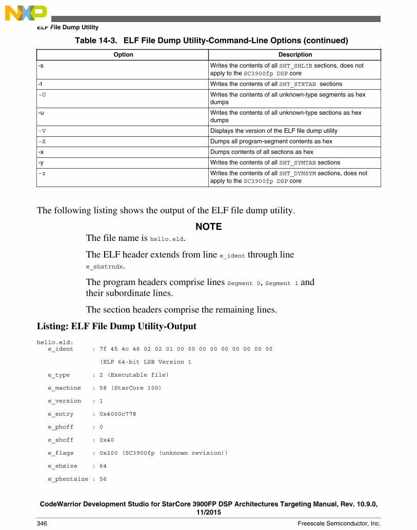
Table 14-3. ELF File Dump Utility-Command-Line Options (continued)
Option Description
-s Writes the contents of all SHT_SHLIB sections, does notapply to the SC3900fp DSP core
-t Writes the contents of all SHT_STRTAB sections
-U Writes the contents of all unknown-type segments as hexdumps
-u Writes the contents of all unknown-type sections as hexdumps
-V Displays the version of the ELF file dump utility
-X Dumps all program-segment contents as hex
-x Dumps contents of all sections as hex
-y Writes the contents of all SHT_SYMTAB sections
-z Writes the contents of all SHT_DYNSYM sections, does notapply to the SC3900fp DSP core
The following listing shows the output of the ELF file dump utility.
NOTEThe file name is hello.eld.
The ELF header extends from line e_ident through linee_shstrndx.
The program headers comprise lines Segment 0, Segment 1 andtheir subordinate lines.
The section headers comprise the remaining lines.
Listing: ELF File Dump Utility-Output
hello.eld: e_ident : 7f 45 4c 46 02 02 01 00 00 00 00 00 00 00 00 00
(ELF 64-bit LSB Version 1
e_type : 2 (Executable file)
e_machine : 58 (StarCore 100)
e_version : 1
e_entry : 0x4000c778
e_phoff : 0
e_shoff : 0x40
e_flags : 0x200 (SC3900fp (unknown revision))
e_ehsize : 64
e_phentsize : 56
ELF File Dump Utility
CodeWarrior Development Studio for StarCore 3900FP DSP Architectures Targeting Manual, Rev. 10.9.0,11/2015
346 Freescale Semiconductor, Inc.

e_phnum : 6
e_shentsize : 64
e_shnum : 24
e_shstrndx : 23
Segment 0:
p_type : PT_LOAD
p_offset : 0x190
p_vaddr : 0x40000000
p_paddr : 0x40000000
p_filesz : 12
p_memsz : 12
p_flags : 0x6 PF_R PF_W
p_align : 4
Segment 1:
p_type : PT_LOAD
p_offset : 0x1a0
p_vaddr : 0x40001000
p_paddr : 0x40001000
p_filesz : 200
p_memsz : 200
p_flags : 0x4 PF_R
p_align : 8
Section 0:
sh_name :
sh_type : SHT_NULL
sh_flags : 0
sh_addr : 0
sh_offset : 0
sh_size : 0
sh_link : 0
sh_info : 0
sh_addralign : 0
sh_entsize : 0
Section 1:
sh_name : ddr_shared_data_nc_wt
Chapter 14 StarCore DSP Utilities
CodeWarrior Development Studio for StarCore 3900FP DSP Architectures Targeting Manual, Rev. 10.9.0,11/2015
Freescale Semiconductor, Inc. 347

sh_type : SHT_STARCORE_OVERLAY
sh_flags : 0x3 SHF_WRITE SHF_ALLOC
sh_addr : 0x40000000
sh_offset : 0x190
sh_size : 12
sh_link : 0
sh_info : 0
sh_addralign : 4
sh_entsize : 0
.
.
.
14.4 ELF2XX Utility
Use the ELF2XX utility to write the information within the executable ELF file in userspecific format such as srec, lod, or bin.
To invoke the ELF2XX utility from the command prompt, type:
sc100-elf2xx [option ...] <input-file>
NOTEThe ELF to S-Record utility is in this directory:
<CWinstallDir>\SC\StarCore_Support\compiler\bin
Parameters
option
Table 14-4 defines the purpose and effect of each command-line option.
input-file
The filename of the ELF object file.
Listing: LOD File-Format
_START Module_ID Version Rev# Device# Asm_Version Comment_END Entry_point_address
_DATA Memory_space Address Code_or_Data
ELF2XX Utility
CodeWarrior Development Studio for StarCore 3900FP DSP Architectures Targeting Manual, Rev. 10.9.0,11/2015
348 Freescale Semiconductor, Inc.

_BLOCKDATA Memory_space Address Count Value
_SYMBOL Memory_space Symbol_Address ...
_COMMENT Comment
Listing: BIN File-Format
ENDIANNESS_BYTE (1Byte)
<ADDRESS - 8Bytes><SIZE_IN_BYTES - 8Bytes><data_payload>
<ADDRESS - 8Bytes><SIZE_IN_BYTES - 8Bytes><data_payload>
....
<ADDRESS -8Bytes><SIZE_IN_BYTES - 8Bytes><data_payload><ADDRESS = 0x00000000C007B010><SIZE = 8><value_of_entrypoint>
NOTEENDIANNESS_BYTE has the value 2 for MSB and 1 for LSB. This featurecan be used to dump the executable .elf file into a fastdownload format. The file can be parsed and loaded into target'smemory.
Table 14-4. elf2xx Utility-Command-Line Options
Option Description Type
-t <output-type> Sets the output type format <output-type> is one of: srec, lod , eld, , orbin
Mandatory
-DumpUninitializedData= Off Inhibits to dump the information aboutthe Uninitialized Data <BSS sections>
Optional
-DumpUninitializedData= On Enables to dump the information aboutthe Uninitialized Data <BSS sections>
-DumpNewLine=Off Inhibits dumping new line for the srecformat
Optional
-DumpNewLine=On Enables dumping new line for the srecformat.
-entry_address HEX_VALUE Enables the user to change the defaultvalue of the address, where the entrypoint is written, to the specifiedHEX_VALUE. The HEX_VALUE must bewritten as "0xNUMBER" (for example:0xC007B010)
NOTE: This option is valid only for thebin format.
-m <arch> -#<value> <list_eld>{ #<value> <list_eld> ...}
Enables us to merge one or moreapplications. The result of merger can bespecified by the output-type argumentfrom -t option. <arch> is one ofb4420, b4860 <value> is the index ofcore. For example, -#0 means core
Table continues on the next page...
Chapter 14 StarCore DSP Utilities
CodeWarrior Development Studio for StarCore 3900FP DSP Architectures Targeting Manual, Rev. 10.9.0,11/2015
Freescale Semiconductor, Inc. 349

Table 14-4. elf2xx Utility-Command-Line Options (continued)
Option Description Type
zero. <list_eld> is the list ofexecutable ELF file that are delimited byspace.
-merge-with-symbol-information=On
Enables dumping in merged .eld filesymbol information.
-merge-with-symbol-information=Off
Disables dumping in merged .eld filesymbol information. This is defaultbehaviour.
-split <arch> Enables us to split an executable ELDfile into multiple core specific ELD files.<arch> is one of: b4420, b4860
-o <output-file> Redirects the output to the specified file;standard output is used in case the file/output is missing
Optional
-removeAllBss Generates a srec file that does notcontain records for the bss sections.The tool will read the bss table from theinput .eld file.
-V Displays the current version of thesc100-elf2xx utility.
-ccsr_address HEX_VAL Defines the CCSR start address of thefirst StarCore core. This information willbe used by the tool to generate the .binfiles entries that will be used by theloader to program the MMU descriptors.For B4860 the value is 0xffec40000.
Valid only for bin format.
When using the output file, after loading the information into memory, the host has towrite 0xa5a5a5a5 to 0xC007B000 in order to finalize the download process.
NOTEEven if the user program uses only one core, private data for theother cores must also be included in the output file for properboot operation.
For example, the user program generates the following output files for each of the cores:
• Core 0, project.eld• Core 1, c1_project.eld• Core 2, c2_project.eld• Core 3, c3_project.eld
ELF2XX Utility
CodeWarrior Development Studio for StarCore 3900FP DSP Architectures Targeting Manual, Rev. 10.9.0,11/2015
350 Freescale Semiconductor, Inc.

To create an S-record output called led_output.s from the combined object files, the sc100-elf2xx utility is called, as the code in the following listing shows. The -t srec selects an S-record output format. The -o led_output.s specifies the name of the output file. The -mb4860 selects the device. Finally, all four input .eld files specify the object code tocombine.
Listing: Running ELF2XX Utility for Multiple Input Files
installDir\SC\StarCore_Support\compiler\bin >sc100-elf2xx -t srec -o led_output.s -m b4860 -#0 project.eld -#1 c1_project.eld -#2 c2_project.eld -#3 c3_project.eld
To create an S-record output without any .bss section records, the sc100-elf2xx utility iscalled as shown in the following listing.
Listing: Running ELF2XX Utility for Multiple Input Files
installDir\SC\StarCore_Support\compiler\bin >sc100-elf2xx -t srec -DumpUninitializedData=Off -removeAllBss bss_table_file.txt -m b4860 -#0 project.eld -#1 c1_project.eld -#2 c2_project.eld -#3 c3_project.eld
-removeAllBss bss_table_file.txt option ensures that all the bss sections are eliminated,no mater where they are placed, based on the information in the bss_table_file.txt file.
This section contains the following topic:• L1 Defense Support• Extract core specific images from multicore image
14.4.1 L1 Defense Support
This section describes the L1 defense support in the elf2xx utility for StarCore 3900FPDSPs.
When reloading a core’s image, the loader must know what it should load withoutinterfering with the running state of the other cores. In order to be able to do this, theloader (debugger or boot loader) must know which parts of the image are private andwhich are shared. It loads only the private parts or, in case multiple cores are restarted,also the image parts shared between the restarted and reloaded cores.
Based on the information in the segment header, the sc100-elf2xx tool generates multipleimages for each core: one containing the private code, and some other – one for eachsharing space (cluster, multiple clusters, whole platform). Based on the output name, youwill know to which cores each file corresponds.
You can use the following command:
Chapter 14 StarCore DSP Utilities
CodeWarrior Development Studio for StarCore 3900FP DSP Architectures Targeting Manual, Rev. 10.9.0,11/2015
Freescale Semiconductor, Inc. 351
sc100-elf2xx -t bin -o binary_image.bin -SeparateBinFiles=On -DumpUninitializedData=Off -m b4860 -entry_address 0xFFFFFFFFFFFFFFFF -ccsr_address 0xffec40000 -#0 test.eld -#1 c1_test.eld -#2 test.eld -#3 test.eld -#4 c4_test.eld -#5 c5_test.eld
The generated files name appears as:
<visible_cores>_binary_image.bin
Where visible_cores represents the cores that the image is visible on. Syntax is:
<visible_cores> = -cX_ if the segment is private -cX_c(X+1) if the segment is shared on one cluster
Example,
If one segment is private on core c0, the image will be emitted in file:
c0_binrary_image.bin
if one segment is shared on cluster 0, the image name will be:
c0_c1_binary_image.bin
if the segment is shared on the whole platform, the image name will be:
c0_c1_c2_c3_c4_c5_binary_image.bin
if the segment is shared among cluster 0 and 2, the image name will be:
c0_c1_c4_c5_binary_image.bin
This behavior is available only for the .bin output format.
Each image will contain the necessary information for the loader to program the MMUdescriptors.
14.4.2 Extract core specific images from multicore image
This feature allows you to extract the core specific ELD images from a multicore ELDimage which must be generated by using sc100-elf2xx. The listing below shows how tocreate multicore image from the core specific images.
Listing: Creating multicore image from core specific images
installDir\SC\StarCore_Support\compiler\bin >sc100-elf2xx -t eld -m b4860 -#0 project.eld -#1 c1_project.eld -#2 c2_project.eld -#3 c3_project.eld -#4 c4_project.eld -#5 c5_project.eld -merge-with-symbol-information=On -o project.elf
The core specific images are extracted from the multicore image by using sc100-elf2xx,as shown by the listing below.
Listing: Extract core specific images
ELF2XX Utility
CodeWarrior Development Studio for StarCore 3900FP DSP Architectures Targeting Manual, Rev. 10.9.0,11/2015
352 Freescale Semiconductor, Inc.

installDir\SC\StarCore_Support\compiler\bin >sc100-elf2xx -t eld -split b4860 project.elf -o project.eld
An ELD image is created for each core that has private segments in the multicore ELDimage.
The image corresponding to core 0 will have the same name as the one provided to the -ooption (project.eld). The same name is used for the images corresponding the other coresbut prefixed by the core identifier (c1_project.eld for core 1 and so on).
In order for the extracted core specific images to have the same contents (including debuginformation) as the original images used to create the multicore image, the multicoreimage should include symbol information. This behaviour is enabled by using the -merge-with-symbol-information=On command line option. Not specifying this option or setting it tooff results in a multicore image that does not include symbol information andconsequently, the core specific images obtained from splitting it will not include symbolinformation.
14.5 Name Utility
Use the name utility to display the symbolic information in each object file and librarypassed on the command line.
If a file contains no symbolics, the utility reports this fact.
To invoke the name utility from the command prompt, type:
sc100-nm [-option ...] file ...
NOTEThe sc100-nm utility is in this directory:
<CWinstallDir>\StarCore_Support\compiler\bin
Parameters
option
Table 14-5 defines the purpose and effect of each command-line option.
NOTEName utility command-line options are case-sensitive.
file
Chapter 14 StarCore DSP Utilities
CodeWarrior Development Studio for StarCore 3900FP DSP Architectures Targeting Manual, Rev. 10.9.0,11/2015
Freescale Semiconductor, Inc. 353
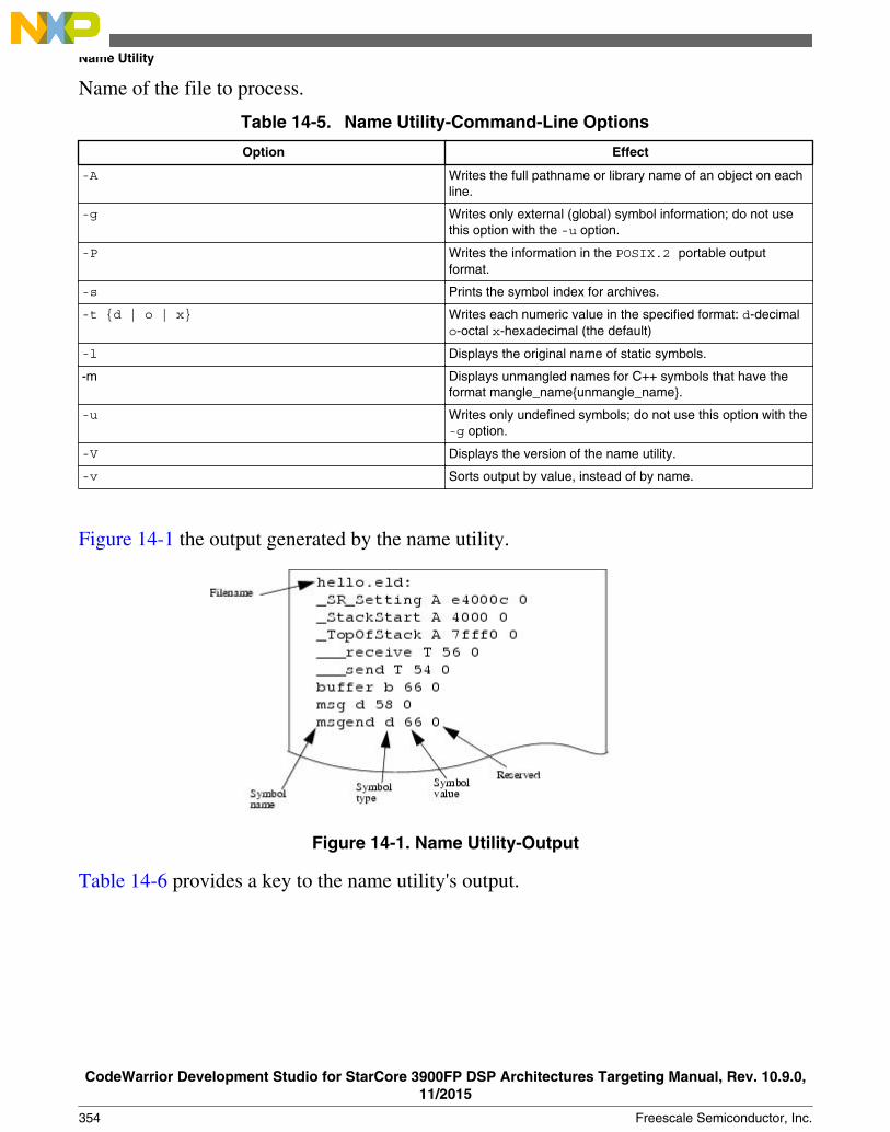
Name of the file to process.
Table 14-5. Name Utility-Command-Line Options
Option Effect
-A Writes the full pathname or library name of an object on eachline.
-g Writes only external (global) symbol information; do not usethis option with the -u option.
-P Writes the information in the POSIX.2 portable outputformat.
-s Prints the symbol index for archives.
-t {d | o | x} Writes each numeric value in the specified format: d-decimalo-octal x-hexadecimal (the default)
-l Displays the original name of static symbols.
-m Displays unmangled names for C++ symbols that have theformat mangle_name{unmangle_name}.
-u Writes only undefined symbols; do not use this option with the-g option.
-V Displays the version of the name utility.
-v Sorts output by value, instead of by name.
Figure 14-1 the output generated by the name utility.
Figure 14-1. Name Utility-Output
Table 14-6 provides a key to the name utility's output.
Name Utility
CodeWarrior Development Studio for StarCore 3900FP DSP Architectures Targeting Manual, Rev. 10.9.0,11/2015
354 Freescale Semiconductor, Inc.

NOTEThe uppercase letters indicate global symbols, while thelowercase letters indicate local symbols.
Table 14-6. Name Utility-Output Key
Character Symbol Type
U Undefined reference
A or a Absolute symbol
B or b BSS symbol
T or t Text (code) symbol
D or d Data symbol
R or r Read-only data symbol
N Debug symbol
? Unknown symbol type or binding
14.6 Size Utility
Use the Size utility to output the size (in bytes) of each section of each ELF object filepassed on the command line.
The default output lists totals for all .text, .rodata, .data, and .bss sections.
To invoke Size utility from the command prompt, type:
sc100-size [-option ...] file ...
NOTEThe sc100-size utility is in this directory:
<CWinstallDir>\StarCore_Support\compiler\bin
Parameters
option
Table 14-7 defines the purpose and effect of each command-line option.
NOTESize utility command-line options are case-sensitive.
file
Chapter 14 StarCore DSP Utilities
CodeWarrior Development Studio for StarCore 3900FP DSP Architectures Targeting Manual, Rev. 10.9.0,11/2015
Freescale Semiconductor, Inc. 355

Name of an ELF file.
Table 14-7. Size Utility-Command-Line Options
Option Description
-l Specifies long listing mode: outputs names and sizes ofindividual sections.
-n Outputs the sizes of individual sections that do not get loaded.
-p Outputs the size of all loadable segments (program view).
-V Displays the version of the size utility.
Figure 14-2 shows two examples of size utility output.
• The default output, at the upper left, lists the totals of all text, rodata, data, and bsssections of the object file. It shows 148 text bytes, 72 data bytes, and 24 bss bytes.
• The lower right output example shows the long-listing format for the same objectfile. It shows that the 72 data bytes are in two files of 48 and 24 bytes.
Figure 14-2. Size Utility-Output
Size Utility
CodeWarrior Development Studio for StarCore 3900FP DSP Architectures Targeting Manual, Rev. 10.9.0,11/2015
356 Freescale Semiconductor, Inc.

Index
A
about 222Accompanying documentation 18Actions 177Action Type 296Add flash device 280Add Flash Programmer Actions 281Adding a Register Group 180Adding Memory Monitor 183Adding Memory Rendering 185Additional Arguments 82, 98Address 300Address lines 301Advanced tab 162alias 222Archiver Utility 337Arguments 111Assembler 20, 71Attach 107Auto-Build Mode 45Automatic Path Mapping 202
B
Bit Fields 175bp 222Build (if required) before launching 110Building Projects 43Build Properties 47Build Properties for StarCore 48Build Settings Page 32Bus noise 300
C
C/C++ application 109C/C++ Language 61C/C++ Options 57Cache View 188Cache View Toolbar Menu 190C Compiler 20CCSSIM2 ISS 145CCSSIM2 PACC 146cd 223change 224Changing Bit Fields 176Changing Build Properties 47Changing Program Counter Value 191Checksum actions 284cls 226Code and Language Options 84Code editing 23
CodeWarrior Bareboard Project Wizard 27CodeWarrior Command-Line Debugging 215CodeWarrior Connection Server 141CodeWarrior Development Studio tools 19CodeWarrior IDE 22CodeWarrior Profiling and Analysis tools 21CodeWarrior TAP 154CodeWarrior TAP - JTAG Connection throughEthernet 157CodeWarrior TAP - JTAG Connection throughUSB 156Command-Line Debugging Tasks 220Common 124Compiler Front End Messages 68Compiling 24config 226Configuration Files 81Configure flash programmer target task 280Configuring CCS 143Configuring Connections 140Connect 108Connection types 144Contents of this manual 17Control 63copy 228Create a CodeWarrior Bareboard Project Page 28Create a flash programmer target task 278Creating a JTAG Initialization File 261Creating CodeWarrior Bareboard Project 35Creating hardware diagnostics task 294Creating MMU Configuration 316Creating Projects 35Creating task for import/export/fill memory 303CustomCustomizing Debug Configurations 129
D
Data lines 301debug 229Debug 114Debug Configurations 103Debugger 21, 112Debugger Shell Command List 221Debugging 24Debugging a CodeWarrior project 134Debugging a Project using Target Hardware 137Debugging Externally Built Executable Files 199Debugging Multi-Core Projects 262Debugging Multiple Cores 268Debugging Project Using Simulator 134Debug Session Type 105Debug Target Settings Page 30, 198
Index
CodeWarrior Development Studio for StarCore 3900FP DSP Architectures Targeting Manual
Freescale Semiconductor, Inc. 357

Debug the Executable File 209Deleting Projects 46Description 178Diagnostics actions 285dir 229disassemble 230Disassembler Settings 53Disassembler Utility 339display 231Displaying CCS Console 142Download 108, 115Dump Flash actions 286Duplicate action 287
E
Eclipse IDE 19Editing a Register Group 181Editing remote system configuration 158Edit the Launch Configuration 201ELF2XX Utility 348ELF File Dump Utility 344Environment 123Erase/Blank check actions 282Erasing flash device 293Ethernet TAP 147evaluate 233Exception Configurator 311Execute flash programmer target task 288Execute host-based Scope Loop on target 302Execute target-based Memory Tests on target 303Execution of Script Files 218Exporting memory to file 307
F
Fill Memory 308finish 234fl::blankcheck 234fl::checksum 234fl::device 235fl::diagnose 235fl::disconnect 235fl::dump 235fl::erase 236fl::image 236fl::protect 236fl::secure 237fl::target 237fl::verify 237fl::write 238Flash File to Target 291Flash programmer 277Flash Programmer Use Case 289funcs 238
G
General 318, 333getIDEpref 239getpid 239Gigabit TAP 151Gigabit TAP + Trace 149go 239Go to Address 187
H
Hard resetting 192Hardware Configuration 64Hardware diagnostics 294help 240history 240How to use Flash programmer to write ubootimages 289
I
Import/Export/Fill memory 303Import a CodeWarrior Executable file Page 195Import a CodeWarrior Executable file Wizard 194Import an Executable File 199Import C/C++/Assembler Executable Files Page196Importing data into memory 305Importing Projects 38Importing SmartDSP OS Project 38Include Search Paths 73, 88Initialization tab 159Introduction 17
J
jtagclock 241
K
kill 241
L
L1 Defense Support 351launch 242Libraries 58Linker 21, 72Linker Settings 56Linking 24Listing Contents 94Listing File 92Listing Format 96loadsym 242log 242
Index
CodeWarrior Development Studio for StarCore 3900FP DSP Architectures Targeting Manual
358 Freescale Semiconductor, Inc.

Loop Speed 297
M
Macros 75Main 104Manual-Build Mode 43Manual Path Mapping 204Maple Memory Management Unit Configurator 331Maple MMU Configurator View 331Maple MMU Configurator View Menu 336Maple MMU Configurator View Pages 332mc::config 243mc::go 243mc::group 244mc::kill 244mc::reset 244mc::restart 244mc::stop 245mc::type 245mem 245Memory Access 297Memory Configuration File 213Memory Management Unit Configurator 315Memory tab 160Memory Tests 298Memory test use cases 302MMU Configuration File Editor Pages 318MMU Configurator View 328MMU Configurator View Toolbar 325MMU Editor Menu 324Multi-Core Commands in CodeWarrior IDE 273Multi-Core Commands in Debugger Shell 274Multi-Core Debugging 261Multi-Core Debugging Commands 272
N
Name Utility 353new_file.mmu 323next 247nexti 248
O
oneframe 248Optimization 78OS Awareness 120Other Executables 117Output Listing 65
P
Per Core Reset 192Preprocessor 90Preprocessor Settings 100Processor 77
Processor Page 29, 197Program/Verify actions 283Program MATT 320Programming file 293Project files 23Protect/Unprotect actions 286protocol 248pwd 248
Q
quitIDE 249
R
radix 249redirect 250refresh 250reg 250Registers View Context Menu 178Release notes 17Remove action 287Remove Breakpoints using Breakpoints View 167Remove Breakpoints using Marker Bar 167Remove Hardware Breakpoints using DebuggerShell 169Remove Hardware Breakpoints using the IDE 168Removing a Register Group 181Removing Breakpoints 167Removing Hardware Breakpoints 168Removing Memory Rendering 186Removing Watchpoints 172reset 250Resetting to Base Address 186Resolution of Conflicting Command Names 218restart 251restore 251Restoring Build Properties 48Reverting Debug Configuration Settings 131run 251Running CCS 142
S
save 251Saving Generated Assembly Code 327Saving Generated C Code 326Saving Generated TCL Script 327Saving MMU Configuration 325Saving MMU Configuration File Editor Settings326sc::getPhysicalAddress 253sc::setMaxAccessLength 252sc::setReset 253setpc 253setpicloadaddr 253Setting Breakpoints 163
Index
CodeWarrior Development Studio for StarCore 3900FP DSP Architectures Targeting Manual
Freescale Semiconductor, Inc. 359

Setting Hardware Breakpoints 166Setting Launch Configurations 263Setting Stack Depth 193Setting Watchpoints 170Size Utility 355SmartDSP OS Page 34Source 121Specify target RAM settings 281Specify the Source Lookup Path 201stack 254StarCore 3900 Assembler 83StarCore 3900 C/C++ Compiler 60StarCore 3900 C/C++ Linker Application 55StarCore 3900 Disassembler 52StarCore 3900 Preprocessor 99StarCore DSP Utilities 337StarCore Environment 50status 254step 254stepi 255stop 255switchtarget 256Symbolics 118system 256
T
Target Initialization File 211Target settings 111Tcl Startup Script 219Tcl Support 218Trace and Profile 125Translations 334
U
USB TAP 153Using Debug Configurations Dialog Box 103Using Debugger Shell to Set Hardware Breakpoints166Using IDE to Set Hardware Breakpoints 166
V
var 257Viewing Cache 187Viewing memory 182Viewing Register Details 174
W
wait 258Walking Ones 299Warnings 67watchpoint 259Working with Breakpoints 163Working with Debugger 133
Working with Debugger Shell 215Working with Hardware Diagnostic Action editor295Working with Hardware Tools 277Working with Projects 27Working with Register Groups 179Working with Registers 172Working with Watchpoints 169
Index
CodeWarrior Development Studio for StarCore 3900FP DSP Architectures Targeting Manual
360 Freescale Semiconductor, Inc.

How to Reach Us:
Home Page:freescale.com
Web Support:freescale.com/support
Information in this document is provided solely to enable system andsoftware implementers to use Freescale products. There are no expressor implied copyright licenses granted hereunder to design or fabricateany integrated circuits based on the information in this document.Freescale reserves the right to make changes without further notice toany products herein.
Freescale makes no warranty, representation, or guarantee regardingthe suitability of its products for any particular purpose, nor doesFreescale assume any liability arising out of the application or use ofany product or circuit, and specifically disclaims any and all liability,including without limitation consequential or incidental damages.“Typical” parameters that may be provided in Freescale data sheetsand/or specifications can and do vary in different applications, andactual performance may vary over time. All operating parameters,including “typicals,” must be validated for each customer application bycustomer's technical experts. Freescale does not convey any licenseunder its patent rights nor the rights of others. Freescale sells productspursuant to standard terms and conditions of sale, which can be foundat the following address: freescale.com/SalesTermsandConditions.
Freescale, the Freescale logo, CodeWarrior, QorIQ, StarCore aretrademarks of Freescale Semiconductor, Inc., Reg. U.S. Pat. & Tm. Off.QorIQ Qonverge is a trademark of Freescale Semiconductor, Inc. Allother product or service names are the property of their respectiveowners. The Power Architecture and Power.org word marks and thePower and Power.org logos and related marks are trademarks andservice marks licensed by Power.org.
© 2008–2015 Freescale Semiconductor, Inc. All rights reserved.
Document Number CWSCDBGUGRevision 10.9.0, 11/2015