
COBRA-FLX: A Core Thermal-Hydraulic ~~~~;~n361 Analysis …
26
'· A .AREVA COBRA-FLX: A Core Thermal-Hydraulic Analysis Code Errata 1NP-ooo May 2017 AREVA Inc. (c) 2017 AREVA Inc.
Transcript of COBRA-FLX: A Core Thermal-Hydraulic ~~~~;~n361 Analysis …

'·
A .AREVA
COBRA-FLX: A Core Thermal-Hydraulic ~~~~;~n361
Analysis Code Errata 1NP-ooo
May 2017
AREVA Inc.
(c) 2017 AREVA Inc.
Copyright© 2017
AREVA Inc. All Rights Reserved
ANP-10311 Revision 0
Errata 1 NP-000
AREVA Inc.
COBRA-FLX: A Core Thermal-Hydraulic Analysis Code
Item 1
Section(s) or Page(s) All
Nature of Changes
Description and Justification Initial Issue
ANP-10311 Revision 0
Errata 1 NP-000
Pa e i
AREVA Inc.
COBRA-FLX: A Core Thermal-Hydraulic Analysis Code
1.0 SUMMARY
ANP-1031 1 Revision 0
Errata 1 NP-000
Pa e 1-1
AREVA Inc. (AREVA) is seeking clarification on the use of the standard friction factor
correlation within ANP-10311 PA, Revision 0 "COBRA-FLX: A Core Thermal-Hydraulic
Analysis Code". While the NRC's Safety Evaluation (SE) is clear on the approval of the
Lehmann correlation , approval of the standard friction factor is not apparent. AREVA
believes that the original intent of the reviewer was to approve the standard friction
factor for the following reasons. First, the discussion on the friction factor provided in
Section 3.4 .2 of the SE points out that the standard friction factor correlations "are for
the most part venerable and well validated models in widespread general use in
subchannel codes" and that Lehmann attempts to correct the standard correlation to
account for surface roughness and "entrance effects". The SE argues that, while the
usefulness of the corrections is arguable , they do attempt to capture physical effects
generally ignored in subchannel modeling and results in very small corrections when
applied in the range typical of reactor operations. Additionally, this subject has been
discussed with the NRC in several teleconferences where the NRC verbally confirmed
that the reviewer's original intent was to approve the standard friction factor. Finally,
this is consistent with the wording in Section A.3 .1 of ANP-10311 PA which presents the
Lehmann correlation "as an alternative" to the standard model. AREVA is requesting
written concurrence that the standard friction factor correlation is approved for use in
COBRA-FLX. A markup of Table 1-2 of ANP-10311 PA, Revision 0 has been provided
in Section 1 .1 .
AREVA has also identified several corrections in the COBRA-FLX to L YNXT transient
benchmarking . Section 5.7.2.1 and 5.7.2.2 of ANP-10311 PA, Revision 0 contains an
error in the diversion cross flow resistance factor (Kij). Kii is derived from test results
and is dependent on the code use to analyze the results. Hence, the Kii factor for one
code is not compatible with other codes. In the original benchmarking the COBRA-FLX
based Kii was used in L YNXT. This error has been corrected by using the L YNXT
based Kii and errata have been provided below in Section 1.2. This resulted in changes
to the numbers provided in summary tables; however these changes do not alter the
AREVA Inc.
COBRA-FLX: A Core Thermal-Hydraul ic Analysis Code
ANP-10311 Revision 0
Errata 1 NP-000
Pa e 1-2 conclusions presented in the topical because the benchmarking remains within the
acceptable range. Note that several typos in Section 5.7.2.1 and 5.7.2.2 have also
been corrected .
Additionally, several errata have been provided in Section 1.3. These errata correct
typos and provide clarification of wording . These errata do not impact the code or the
conclusions of the topical report. These errata do not require concurrence. They have
been provided for information and to provide a complete list of corrections to the Topical
Report.
1.1 Friction Factor
The following corrections have been made to ANP-10311 P-A, Revision 0.
Item 1
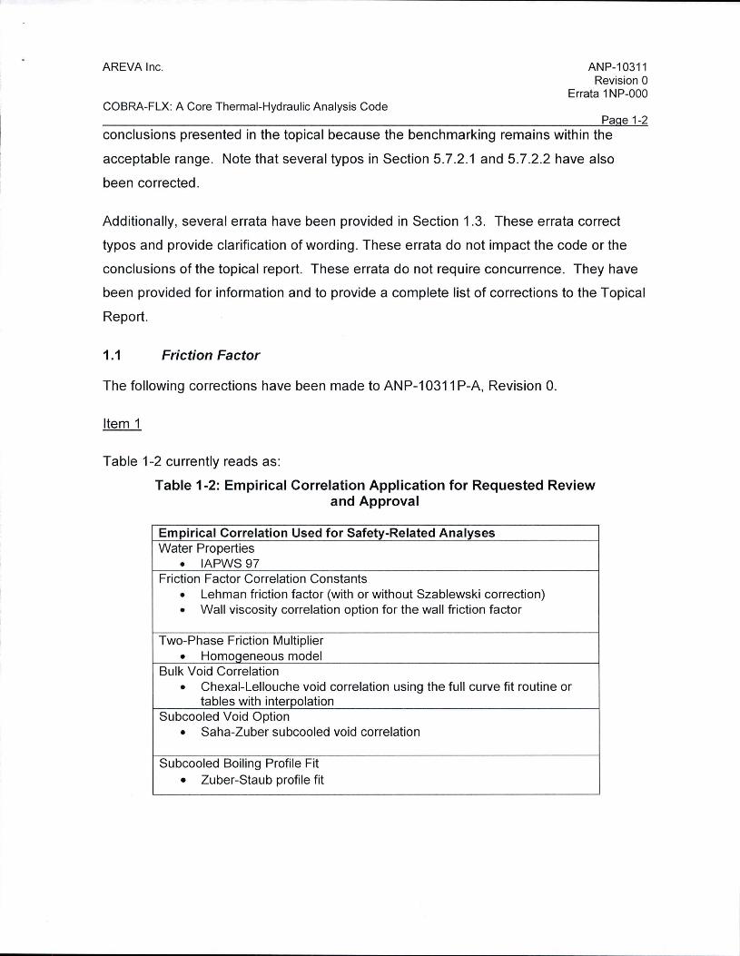
Table 1-2 currently reads as:
Table 1-2: Empirical Correlation Application for Requested Review and Approval
Empirical Correlation Used for Safety-Related Analyses Water Properties
• IAPWS 97 Friction Factor Correlation Constants
• Lehman friction factor (with or without Szablewski correction) • Wall viscosity correlation option for the wall friction factor
Two-Phase Friction Multiplier
• HomoQeneous model Bulk Void Correlation
• Chexal-Lellouche void correlation using the full curve fit routine or tables with interpolation
Subcooled Void Option • Saha-Zuber subcooled void correlation
Subcooled Boiling Profile Fit
• Zuber-Staub profile fit

AREVA Inc.
COBRA-FLX: A Core Thermal-Hydraulic Analysis Code
Table 1-2 should read as:
ANP-10311 Revision 0
Errata 1 NP-000
Pa e 1-3
Table 1-2: Empirical Correlation Application for Requested Review and Approval
Empirical Correlation Used for Safety-Related Analyses Water Properties
• IAPWS 97 Friction Factor Correlation Constants
• Standard • Lehman friction factor (with or without Szablewski correction)
• Wall viscosity correlation option for the wall friction factor
Two-Phase Friction Multiplier • Homoqeneous model
Bulk Void Correlation
• Chexal-Lellouche void correlation using the full curve fit routine or tables with interpolation
-Subcooled Void Option • Saha-Zuber subcooled void correlation
Subcooled Boiling Profile Fit
• Zuber-Staub profile fit
AREVA Inc.
COBRA-FLX: A Core Thermal-Hydraulic Analysis Code
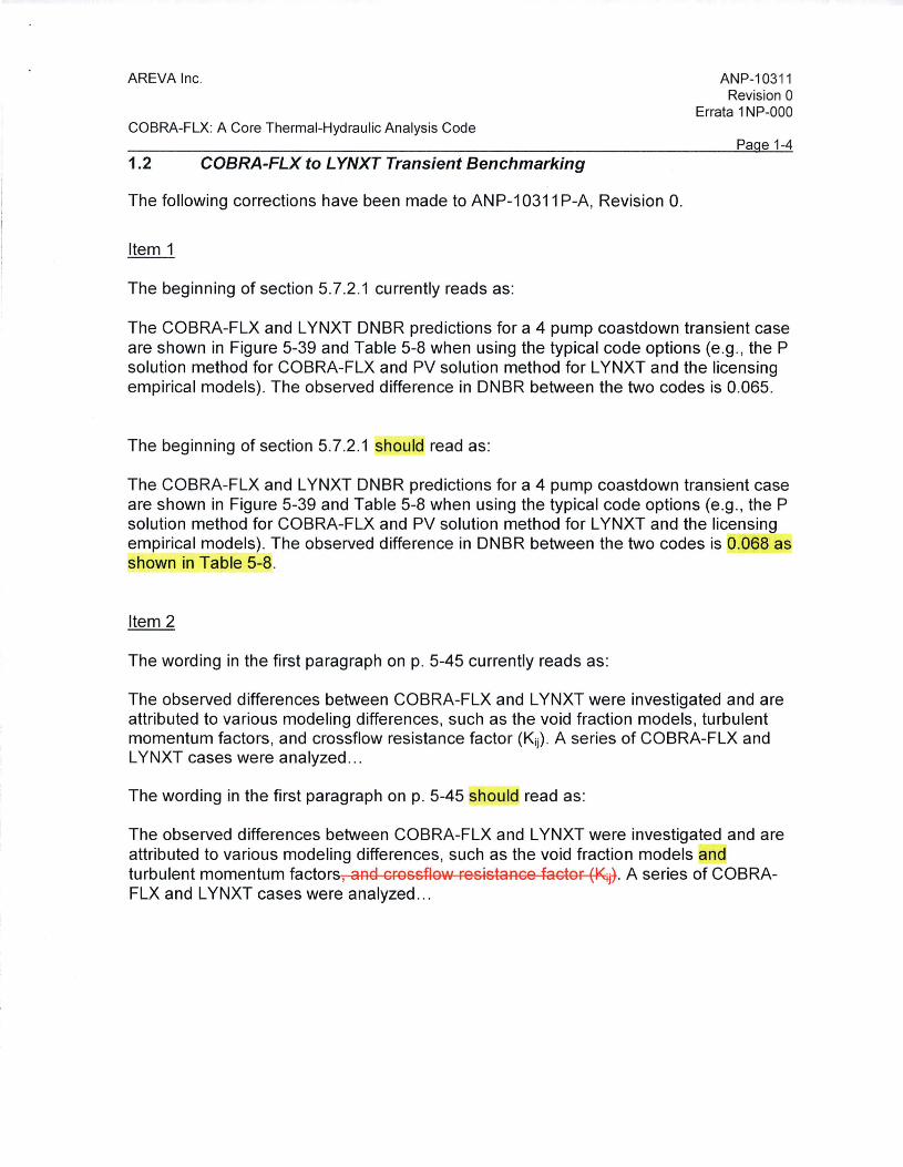
1.2 COBRA-FLX to L YNXT Transient Benchmarking
The following corrections have been made to AN P-10311 P-A, Revision 0.
Item 1
The beginning of section 5. 7 .2.1 currently reads as:
ANP-10311 Revision 0
Errata 1 NP-000
Pa e 1-4
The COBRA-FLX and L YNXT DNBR predictions for a 4 pump coastdown transient case are shown in Figure 5-39 and Table 5-8 when using the typical code options (e.g., the P solution method for COBRA-FLX and PV solution method for L YNXT and the licensing empirical models) . The observed difference in DNBR between the two codes is 0.065.
The beginning of section 5.7.2.1 should read as:
The COBRA-FLX and L YNXT DNBR predictions for a 4 pump coastdown transient case are shown in Figure 5-39 and Table 5-8 when using the typical code options (e.g., the P solution method for COBRA-FLX and PV solution method for L YNXT and the licensing empirical models) . The observed difference in DNBR between the two codes is 0.068 as shown in Table 5-8.
Item 2
The wording in the first paragraph on p. 5-45 currently reads as:
The observed differences between COBRA-FLX and L YNXT were investigated and are attributed to various modeling differences, such as the void fraction models, turbulent momentum factors , and crossflow resistance factor (Kij) . A series of COBRA-FLX and L YNXT cases were analyzed ...
The wording in the first paragraph on p. 5-45 should read as:
The observed differences between COBRA-FLX and L YNXT were investigated and are attributed to various modeling differences, such as the void fraction models and turbulent momentum factors , and crossflow resistance factor (Kijj. A series of COBRAFLX and L YNXT cases were analyzed ...

AREVA Inc. ANP-10311 Revision 0
Errata 1 NP-000 COBRA-FLX: A Core Thermal-Hydraulic Analysis Code
Item 3
Table 5-9 and 5-10 currently read as :
Table ~9: COBRA-FLX and: L YNXT Minimum DNBR Sensitivity t o Modeling Parameters for the 4 Pump Coastd.own
MDNBR (BWCMV-A)
Parameter Parameter COBRA-FLX l YNXT Change
Individually Production Case Using the 1.899 1.84'6 PV Solution Method
Individually Homogenous Vojd Model for 1 .. 920 1.'922 both Cooes
Individually Common Kii for both Codes 1.923 1.846
Individually common Turbulent 1.878 1.84'6
Momentum Factor (FTM)
Combined Combined Effect of AH 1.9385 1.923 Parameters Above
Table 5-10: Summary of DNBR Compariso:n for the 12-Chan e·1 Model for the Locked Rotor
Parameter COBRA-Fil X LYNXT
MDNBR (BWCMV-A) 0.915 0.801
Time at MDNBR (sec} 2 .78. 2.80
Pa e 1-5
AREVA Inc.
COBRA-FLX: A Core Thermal-Hydraulic Analysis Code
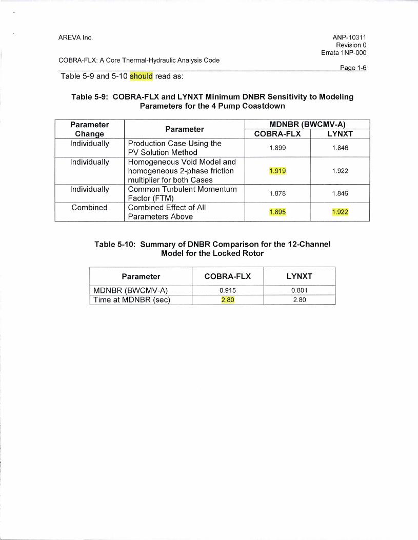
Table 5-9 and 5-10 should read as:
ANP-1031 1 Revision 0
Errata 1 NP-000
Pa e 1-6
Table 5-9: COBRA-FLX and L YNXT Minimum DNBR Sensitivity to Modeling Parameters for the 4 Pump Coastdown
Parameter Parameter
MDNBR (BWCMV-A) Change COBRA-FLX LYNXT
Individually Production Case Using the 1.899 1.846
PV Solution Method Individually Homogeneous Void Model and
homogeneous 2-phase friction 1.919 1.922
multiplier for both Cases Individually Common Turbulent Momentum
1.878 1.846 Factor (FTM)
Combined Combined Effect of All 1.895 1.922
Parameters Above
Table 5-10: Summary of DNBR Comparison for the 12-Channel Model for the Locked Rotor
Parameter COBRA-FLX LYNXT
MDNBR (BWCMV-A) 0.915 0.801
Time at MDNBR (sec) 2.80 2.80

AREVA Inc. ANP-1031 1 Revision 0
Errata 1 NP-000 COBRA-FLX: A Core Thermal-Hydraulic Analysis Code
Item 4
Figures 5-42, 5-43 and 5-44 currently read as:
f;igure 5-42: DNB:R Comparison for the Combined Effect of All 1Modeling Parameters in Tab 'e 5-9 for th.e 4 Pump Coastdown
2.80 ------.....-----------.......------
<"° 2.60 +------+---- --LYNXT ). - COBRA-FLX
:a ~· 2.40
al
0:: 2.20 -l-------= ......... +------1---------"'r---#----~ al z c :i 2.rno -1-----+-----""~1::----~¥-ir--------1
1.ao --------------------1 2 3 4 5
Transient T 1irre. Seconds
Pa e 1-7
AREVA Inc.
COBRA-FLX: A Core Thermal-Hydraulic Analysis Code
ANP-10311 Revision 0
Errata 1 NP-000
Pa e 1-8
!Figure 5-43: Mass Velocity C,omparison for the Combined Effect of All Modeling Parameters in Table 5·9· tor the 4 Pump Coastdown at
the Time of !Minimum DNBR
0.150
~· 0.125 Cl)'
...;,.;.. tn·
.lli:!. 0.100
~· .Q 0.075 G,)·
> U} 0.050 ti). lO ::! 0.025
0.000
..
0
I I - LYNXT
- COBRA-FLX
' ~
100 200 300 400
Axial Height, cm
AREVA Inc.
COBRA-FLX: A Core Thermal-Hydraulic Analysis Code
ANP-10311 Revision 0
Errata 1 NP-000
Pa e 1-9
Fiigure 5-44: Thermodynam:ic 1QuaHty Comparison for the C1ombined; Effect of AH Modeling Parameters 1in Table 5-9 for the 4 Pump·
Coastdown at the Time of M1nimum DNBR
0.15 ~---~----~---~----~
-~ 0.05 (t'I
-LYNXT - C-OBRA-fLX
~ -0.05 +-----+-----+---..,,,,._~,__ ___ --I 0 ~ -0.15 +-----+------t-.,,..__--~f-------1
·c ...0 ·s -0..25 -------+----------------,__ ___ __, i::r Lil
-0.35 +---=r"i=+----+----~f-------I
-0.45 +-----+-----+--------1~-----1
0 100 200 300 400
Axial Height, cm
AREVA Inc. ANP-10311 Revision 0
Errata 1 NP-000 COBRA-FLX: A Core Thermal-Hydraulic Analysis Code
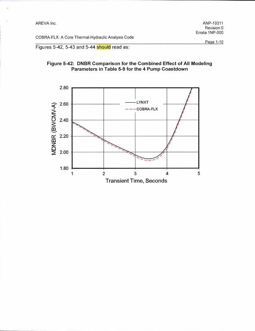
Pa e 1-10 Figures 5-42, 5-43 and 5-44 should read as:
Figure 5-42: DNBR Comparison for the Combined Effect of All Modeling Parameters in Table 5-9 for the 4 Pump Coastdown
2.80 ------------....... ----....... -----
~ 2.60
> ~
--LYNXT
- - - COBRA-FLX
u 2.40 -+--------1------+------+----R-----I
~ .......... 0::: 2.20 4-------'"""'----4-------+-----+--.H------I
Cil z 0 ~ 2.00 -1--------+--------......,__f-----~....+-------I
...._ __ .--1.80 ......,_ ____ ..... _____ .,_ ____ ..... ____ ___.,
1 2 3 4 5
Transient Time, Seconds
L
AREVA Inc.
COBRA-FLX: A Core Thermal-Hydraulic Analysis Code
ANP-1031 1 Revision 0
Errata 1 NP-000
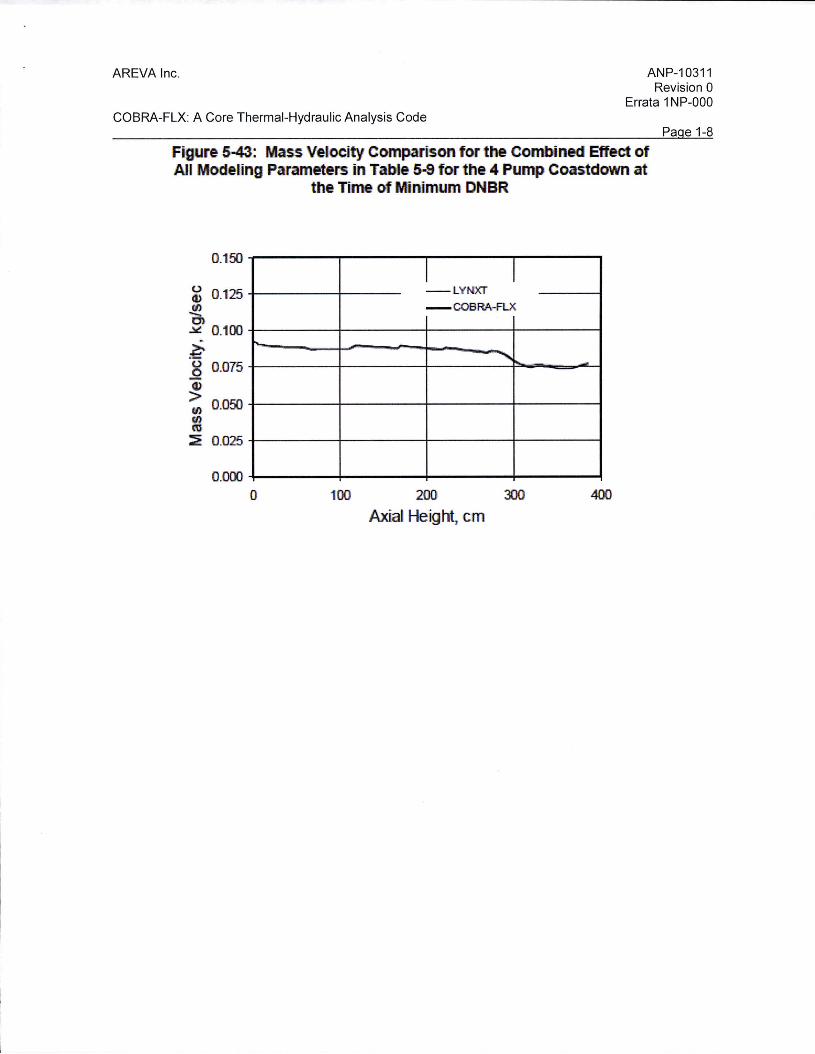
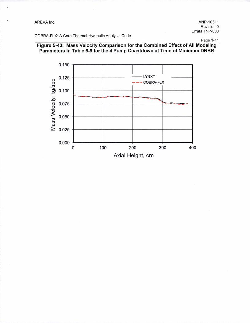
Pa e 1-11 Figure 5-43: Mass Velocity Comparison for the Combined Effect of All Modeling Parameters in Table 5-9 for the 4 Pump Coastdown at Time of Minimum DNBR
0.150
(.) 0.125 Q) Cf) -C) 0.100 ~
~ (.) 0.075 0
~ Cf) 0.050 Cf) ca ~ 0.025
0.000
....
0 100
I I --LYNXT
- - - COBRA-FLX
- ~ -
200 300 400
Axial Height, cm

'-
AREVA Inc.
COBRA-FLX: A Core Thermal-Hydraulic Analysis Code
ANP-10311 Revision 0
Errata 1 NP-000
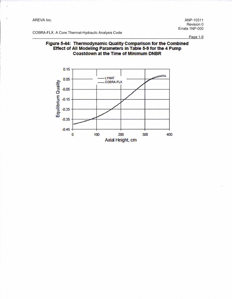
Pa e 1-12 Figure 5-44: Thermodynamic Quality Comparison for the Combined Effect of All Modeling Parameters in Table 5-9 for the 4 Pump Coastdown at Time of Minimum
DNBR
0.15
0.05 --LYNXT
>-- - - COBRA-FLX
:!::: ro -0.05 ::s a E -0.15 ::s
"i:: ..c
-0.25 ::s C"' w
-0.35
-0.45 0 100 200 300 400
Axial Height, cm
Item 5
The beginning of section 5.7.2.2 currently reads as:
A locked rotor transient comparison of COBRA-FLX and L YNXT predictions was performed by substituting the earlier 4 pump coastdown forcing function with a locked rotor forcing function. This substitution results in a more abrupt reduction in DNBR as can be seen in Figure 5-45 with a minimum DNBR difference of 0.093 as shown in Table 5-10.
The beginning of section 5.7.2.2 should read as:
A locked rotor transient comparison of COBRA-FLX and L YNXT predictions was performed by substituting the earlier 4 pump coastdown forcing function with a locked rotor forcing function . This substitution results in a more abrupt reduction in DNBR as can be seen in Figure 5-45 with a minimum DNBR difference of 0.114 as shown in Table 5-10.
AREVA Inc.
COBRA-FLX: A Core Thermal-Hydraulic Analysis Code
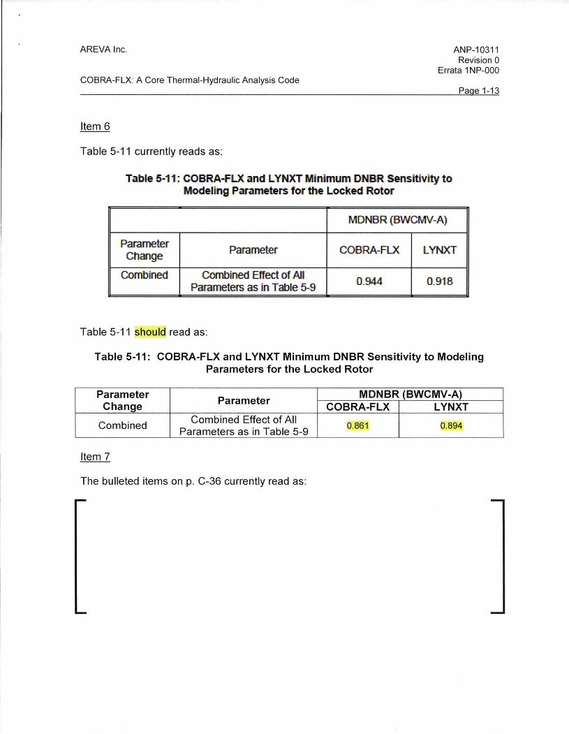
Item 6
Table 5-11 currently reads as:
ANP-1031 1 Revision 0
Errata 1 NP-000
Pa e 1-13
Table 5-11.: COBRA-FLX and LYNXT !Minimum DNB'R Sensitivtty t o Modeling Parameters for the Locked Rotor
MONBR (IBWCMV-A)
Parameter Parameter COBRA-FLX tYNXT Change
Combined Combined Effect of All 0.944 0.'918 Parameters as in Table 5-9
Table 5-11 should read as:
Table 5-11: COBRA-FLX and L YNXT Minimum DNBR Sensitivity to Modeling Parameters for the Locked Rotor
Parameter Parameter
MDNBR (BWCMV-A) Change COBRA-FLX LYNXT
Combined Combined Effect of All 0.861 0.894
Parameters as in Table 5-9
Item 7
The bulleted items on p. C-36 currently read as:
AREVA Inc.
COBRA-FLX: A Core Thermal-Hydraulic Analysis Code
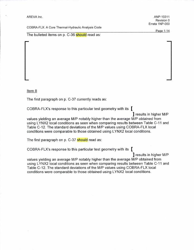
The bulleted items on p. C-36 should read as:
Item 8
The first paragraph on p. C-37 currently reads as:
COBRA-FLX's response to this particular test geometry with its [
ANP-10311 Revision 0
Errata 1 NP-000
Pa e 1-14
] results in higher M/P values yielding an average M/P notably higher than the average M/P obtained from using L YNX2 local conditions as seen when comparing results between Table C-11 and Table C-12 . The standard deviations of the M/P values using COBRA-FLX local conditions were comparable to those obtained using L YNX2 local conditions .
The first paragraph on p. C-37 should read as:
COBRA-FLX's response to this particular test geometry with its [
] results in higher M/P values yielding an average M/P notably higher than the average M/P obtained from using L YNX2 local conditions as seen when comparing results between Table C-11 and Table C-12. The standard deviations of the M/P values using COBRA-FLX local conditions were comparable to those obtained using L YNX2 local conditions.
AREVA Inc.
COBRA-FLX: A Core Thermal-Hydraulic Analysis Code
1.3 Additional Errata
The following errata apply to ANP-10311 P-A Revision 0.
Item 1
The paragraph directly below equation 2-10 currently reads as:
ANP-10311 Revision 0
Errata 1 NP-000
Pa e 1-15
The density of each phase in Equation 2-10 is a function of two independent thermodynamic properties, the pressure and temperature , for example. The equation of state and the transport properties used in COBRA-FLX are discussed later in this report.
The paragraph directly below equation 2-10 should read as:
The saturated density of each phase in Equation 2-10 is a function of the system pressure. The channel cross-sectional density is a function of temperature and pressure when the liquid is subcooled or superheated . The equation of state and the transport properties used in COBRA-FLX are discussed later in this report.
Item 2
The first paragraph of Section 2.2.5.4 currently reads as:
Finally, the equation of state will complete the system of basic equations. All thermodynamic state and transport properties in COBRA-FLX are the saturation properties corresponding to the system pressure. Subcooled liquid properties are calculated at pressure that corresponds to the saturated condition for the given fluid inlet temperature . Superheated vapor properties are available and used for some special applications.
The first paragraph of Section 2.2.5.4 should read as:
Finally, the equation of state will complete the system of basic equations. All thermodynamic state and transport properties in COBRA-FLX are the saturation properties corresponding to the system pressure. Subcooled liquid properties are calculated at pressure that corresponds to the saturated condition for the given local fluid ff:Het temperature. Superheated vapor properties are available and used for some special applications.
AREVA Inc.
COBRA-FLX: A Core Thermal-Hydraulic Analysis Code
Item 3
- ----------------~
ANP-10311 Revision 0
Errata 1 NP-000
Pa e 1-16
In Section 2.3.1.1.1 , the paragraph directly after Figure 2-8 currently reads as:
The spatial derivatives, all only in the axial direction for the subchannel equations, are approximated with the donor-cell approach. Generally, a backward difference from level J is used for the spatial gradients in the continuous equations. Additionally, the quantity being transported is computed as that of the donor cell: the cell , or node , from which the fluid is flowing. For example, the finite-difference form of the mass flux derivative in the mass conservation equation is approximated by
In Section 2.3.1.1 .1, the paragraph directly after Figure 2-8 should read as:
The spatial derivatives, all only in the axial direction for the subchannel equations, are approximated with the donor-cell approach. Generally, a backward difference from level J is used for the spatial gradients in the conservation equations. Additionally , the quantity being transported is computed as that of the donor cell: the cell , or node, from which the fluid is flowing . For example, the finite-difference form of the mass flux derivative in the mass conservation equation is approximated by
Item 4
The statement at the top of page 2-52 currently reads as:
Furthermore, Equation 2-140 is written in the following vector form needed by the SCHEME solution methods:
The statement at the top of page 2-52 should read as:
Furthermore, Equation 2-140 is written in the following matrix form (where [S]T is defined after equation 2-127) needed by the SCHEME solution methods:
AREVA Inc.
COBRA-FLX: A Core Thermal-Hydraulic Analysis Code
Item 5
Section 2.3.2.2.1, the paragraph after equation 2-206 currently reads as:
ANP-10311 Revision 0
Errata 1 NP-000
Pa e 1-17
Thus, -Dk.Pi is analogous to a lateral pressure gradient where a sum is taken on i . The transpose Dk,; performs an operation that is the divergence in the lateral direction . The sign of Dk.Pi accounts for lateral flow into, or out of, the control volume. The array D is very useful to compact and simplify the notation used in the control volume equations. The operations of D are performed in the coding by logic using i(k) and j(k) rather than by actual matrix multiplication. The COBRA-FLX code uses arrays IK(K) and JK(K).
Section 2.3.2.2.1, the paragraph after equation 2-206 should read as:
Thus, -Dk.Pi is analogous to a lateral pressure gradient where a sum is taken on i . The transpose Dk,i performs an operation that is the divergence term in the lateral direction. The sign of Dk,ipi accounts for lateral flow into, or out of, the control volume. The array D is very useful to compact and simplify the notation used in the control volume equations. The operations of D are performed in the coding by logic using i(k) and j(k) rather than by actual matrix multiplication . The COBRA-FLX code uses arrays IK(K) and JK(K).
AREVA Inc.
COBRA-FLX: A Core Thermal-Hydraulic Analysis Code
Item 6
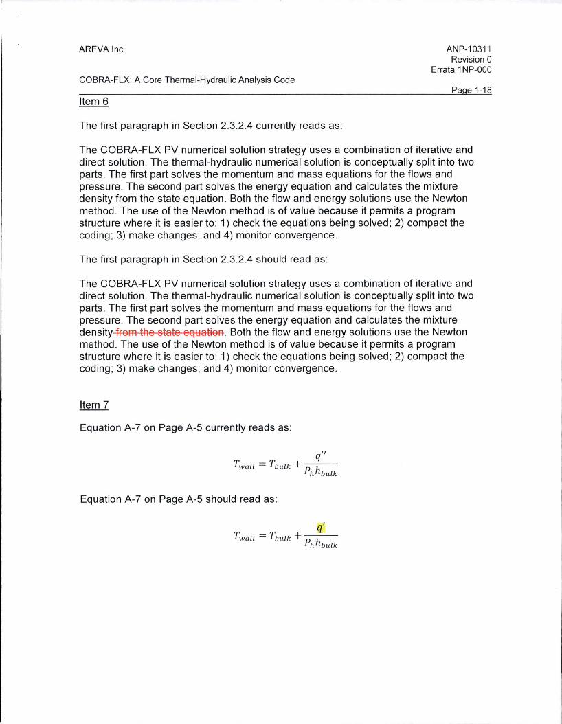
The first paragraph in Section 2.3.2.4 currently reads as:
ANP-1031 1 Revision 0
Errata 1 NP-000
Pa e 1-1 8
The COBRA-FLX PV numerical solution strategy uses a combination of iterative and direct solution . The thermal-hydraulic numerical solution is conceptually split into two parts . The first part solves the momentum and mass equations for the flows and pressure. The second part solves the energy equation and calculates the mixture density from the state equation. Both the flow and energy solutions use the Newton method . The use of the Newton method is of value because it permits a program structure where it is easier to : 1) check the equations being solved ; 2) compact the coding ; 3) make changes ; and 4) monitor convergence.
The first paragraph in Section 2.3.2.4 should read as:
The COBRA-FLX PV numerical solution strategy uses a combination of iterative and direct solution . The thermal-hydraulic numerical solution is conceptually split into two parts. The first part solves the momentum and mass equations for the flows and pressure. The second part solves the energy equation and calculates the mixture density from the state equation . Both the flow and energy solutions use the Newton method . The use of the Newton method is of value because it permits a program structure where it is easier to : 1) check the equations being solved ; 2) compact the coding ; 3) make changes; and 4) monitor convergence .
Item 7
Equation A-7 on Page A-5 currently reads as:
q" Twall = T bul k + p h
h bulk
Equation A-7 on Page A-5 should read as:
Twall = Tbulk + p h h bulk
AREVA Inc.
COBRA-FLX: A Core Thermal-Hydraulic Analysis Code
Item 8
ANP-10311 Revision 0
Errata 1 NP-000
Pa e 1-19
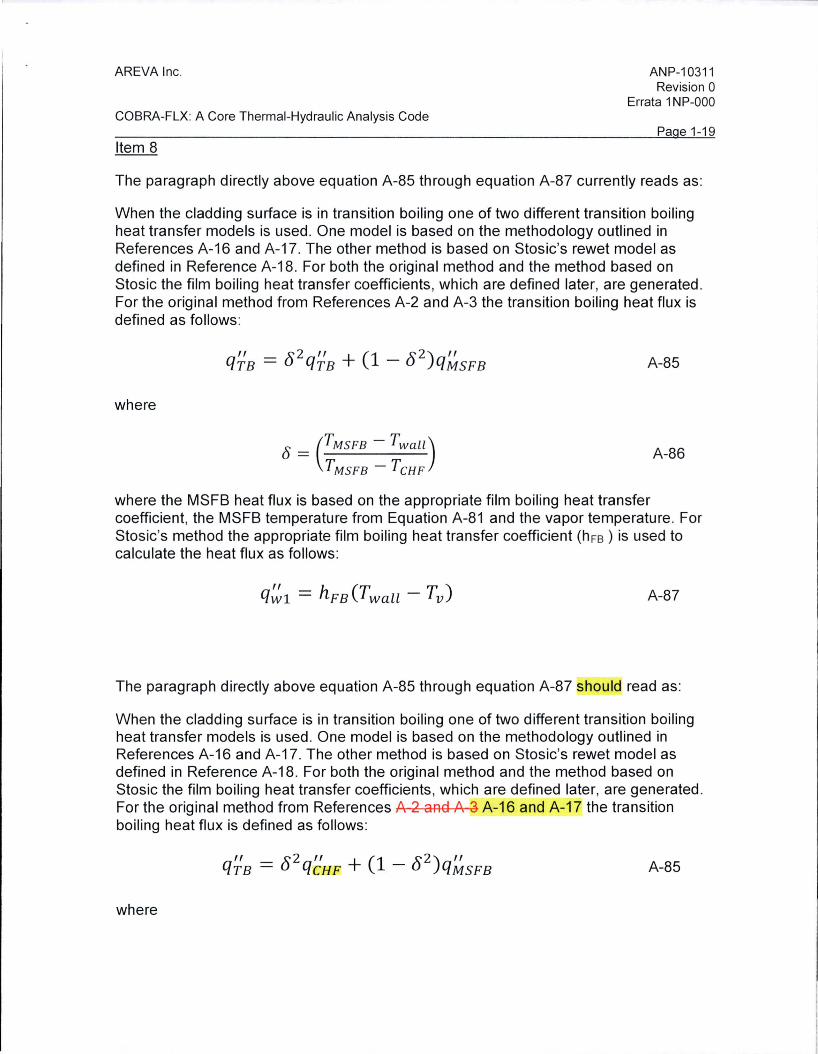
The paragraph directly above equation A-85 through equation A-87 currently reads as:
When the cladding surface is in transition boiling one of two different transition boiling heat transfer models is used. One model is based on the methodology outlined in References A-16 and A-17. The other method is based on Stosic's rewet model as defined in Reference A-18. For both the original method and the method based on Stosic the film boiling heat transfer coefficients , wh ich are defined later, are generated . For the original method from References A-2 and A-3 the transition boiling heat flux is defined as follows :
where
" - .x- 2 " (1 .x- 2) " qTB - u qTB + - u q MSFB
0 = (TMSFB - Twall) TMsFB - TcHF
A-85
A-86
where the MSFB heat flux is based on the appropriate film boiling heat transfer coefficient, the MSFB temperature from Equation A-81 and the vapor temperature . For Stosic's method the appropriate film boiling heat transfer coefficient (h FB ) is used to calculate the heat flux as follows :
A-87
The paragraph directly above equation A-85 through equation A-87 should read as:
When the cladding surface is in transition boiling one of two different transition boiling heat transfer models is used. One model is based on the methodology outlined in References A-16 and A-17. The other method is based on Stosic's rewet model as defined in Reference A-18. For both the original method and the method based on Stosic the film boiling heat transfer coefficients , which are defined later, are generated. For the original method from References A 2 and A 3 A-16 and A-17 the transition boiling heat flux is defined as follows :
" - .x-2 " (1 .x-2) " qTB - u qCB E + - u qMSFB A-85
where
AREVA Inc.
COBRA-FLX: A Core Thermal-Hydraulic Analysis Code
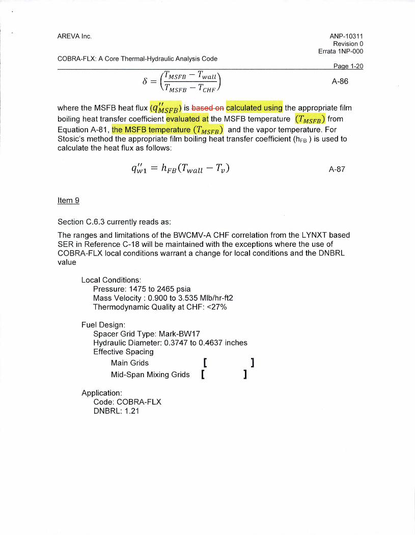
(j = (TMSFB - Twall) TMsFB -TcHF
ANP-10311 Revision 0
Errata 1 NP-000
Pa e 1-20
A-86
where the MSFB heat flux (q~SFB) is based on calculated using the appropriate film
boiling heat transfer coefficient evaluated at the MSFB temperature T SEBJ from Equation A-81, the MSFB temperature (T MSFB) and the vapor temperature. For Stosic's method the appropriate film boiling heat transfer coefficient (hFB ) is used to calculate the heat flux as follows:
A-87
Item 9
Section C.6.3 currently reads as:
The ranges and limitations of the BWCMV-A CHF correlation from the L YNXT based SER in Reference C-18 will be maintained with the exceptions where the use of COBRA-FLX local conditions warrant a change for local conditions and the DNBRL value
Local Conditions: Pressure: 1475 to 2465 psia Mass Velocity: 0.900 to 3.535 Mlb/hr-ft2 Thermodynamic Quality at CHF: <27%
Fuel Design: Spacer Grid Type: Mark-BW17 Hydraulic Diameter: 0.3747 to 0.4637 inches Effective Spacing
Main Grids [ ]
Mid-Span Mixing Grids ( ]
Application : Code: COBRA-FLX DNBRL: 1.21

AREVA Inc.
COBRA-FLX: A Core Thermal-Hydraulic Analysis Code
Section C.6.3 should read as:
ANP-10311 Revision 0
Errata 1 NP-000
Pa e 1-21
The ranges and limitations of the BWCMV-A CHF correlation from the L YNXT based SER in Reference C-18 will be maintained with the exceptions where the use of COBRA-FLX local conditions warrant a change for local conditions and the DNBRL value
Local Conditions: Pressure: 1475 to 2465 psia Mass Velocity: 0.900 to 3.535 Mlb/hr-ft2 Thermodynamic Quality at CHF: <26%
Fuel Design: Spacer Grid Type: Mark-BW17 Hydraulic Diameter: 0.3747 to 0.4637 inches Effective Spacing
Main Grids [
Mid-Span Mixing Grids [ Application:
Item 10
Code: COBRA-FLX DNBRL: 1.21
Table C-11 currently reads as:
] ]
AREVA Inc.
COBRA-FLX: A Core Thermal-Hydraulic Analysis Code
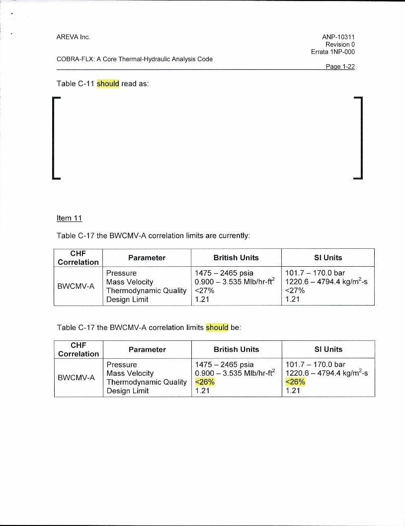
Table C-11 should read as:
Item 11
Table C-17 the BWCMV-A correlation limits are currently:
CHF Parameter British Units Correlation
Pressure 1475 - 2465 psia
BWCMV-A Mass Velocity 0.900 - 3.535 Mlb/hr-ft2
Thermodynamic Quality <27% Design Limit 1.21
Table C-17 the BWCMV-A correlation limits should be:
CHF Parameter British Units Correlation
Pressure 1475 - 2465 psia
BWCMV-A Mass Velocity 0.900 - 3.535 Mlb/hr-ft2
Thermodynamic Quality <26% Design Limit 1.21
ANP-10311 Revision 0
Errata 1 NP-000
Pa e 1-22
SI Units
101 .7 - 170.0 bar 1220.6 - 4794.4 kg/m2-s <27% 1.21
SI Units
101 .7 -170.0 bar 1220.6 -4794.4 kg/m2-s <26% 1.21

AREVA Inc.
COBRA-FLX: A Core Thermal-Hydraulic Analysis Code
Item 12
Table E-1 card group 2 currently reads as:
Card Input Description Group Identifier
Flow correlations
• N 1 = 2 (Saha-Zuber subcooled void correlation)
• N2 = 8, 9 (Chexal-Lellouche void correlation)
• N3 = 0 (homogeneous two-
2 GCC2 phase friction multiplier)
• N4 = 0 (wall viscosity correlction not included)
• N5 = 0 (Lehmann friction factor with the Szablewski correlation)
• N6 = 1 (Zuber-Staub profile fit)
Table E-1 card group 2 should read as:
Card Input Description Group Identifier Flow correlations
• N1 = 2 (Saha-Zuber subcooled void correlation)
• N2 = 8, 9 (Chexal-Lellouche void correlation)
• N3 = 0 (homogeneous two-2 GCC2 phase friction multiplier)
• N4 = 1 (wall viscosit correction included)
• N5 = 0 (Standard* friction factor model)
• N6 = 1 (Zuber-Staub profile fit)
I _ ____ _
ANP-10311 Revision 0
Errata 1 NP-000
Pa e 1-23
Comments
Note that N2 = 9 uses Chexal-Lellouche void correlation using tables with interpolation. This option is advantageous with respect to runtime for large cases, e.g. full core subchannel-by-subchannel calculations.
Comments
Note that N2 = 9 uses Chexal-Lellouche void correlation using tables with interpolation. This option is advantageous with respect to runtime for large cases, e.g. full core subchannel-by-subchannel calculations.
*Note that N5=0, however, since AA>O in card group G2-1, the standard friction facto model is used by default.