
Coaxial electrospinning of liquid crystal-containing … 1 of (page number not for citation...
8
Page 1 of (page number not for citation purposes) 8 Coaxial electrospinning of liquid crystal-containing poly(vinylpyrrolidone) microfibres Eva Enz, Ute Baumeister and Jan Lagerwall * Full Research Paper Open Access Address: Institute of Chemistry – Physical Chemistry, Martin-Luther-University Halle-Wittenberg, Von-Danckelmann-Platz 4, 06120 Halle, Germany Email: Jan Lagerwall * - [email protected] * Corresponding author Keywords: coaxial electrospinning; composite material; core-sheath fibres; liquid crystal; smectic phase Beilstein Journal of Organic Chemistry 2009, 5, No. 58. doi:10.3762/bjoc.5.58 Received: 09 July 2009 Accepted: 22 September 2009 Published: 23 October 2009 Guest Editor: S. Laschat © 2009 Enz et al; licensee Beilstein-Institut. License and terms: see end of document. Abstract With the relatively new technique of coaxial electrospinning, composite fibres of poly(vinylpyrrolidone) with the liquid crystal 4-cyano-4′-octylbiphenyl in its smectic phase as core material could be produced. The encapsulation leads to remarkable confine- ment effects on the liquid crystal, inducing changes in its phase sequence. We conducted a series of experiments to determine the effect of varying the relative flow rates of inner and outer fluid as well as of the applied voltage during electrospinning on these composite fibres. From X-ray diffraction patterns of oriented fibres we could also establish the orientation of the liquid crystal molecules to be parallel to the fibre axis, a result unexpected when considering the viscosity anisotropy of the liquid crystal kept in its smectic phase during electrospinning. Page 1 of (page number not for citation purposes) 8 Introduction Electrospinning is a versatile process for producing nano- and microfibrous materials through electrostatic means. Even though the basic principles have been known for a long time and the first patents on electrospinning go back to 1902 [1,2], there has been a revival of interest since the beginning of the 1990s [3-6]. For laboratory scale purposes the simplest setup for electrospinning consists of three main components: a chargeable spinneret (e.g. a metallic needle) through which a polymer solution or melt is pumped, a grounded collector (e.g. an aluminium foil) and a high voltage power supply connecting spinneret and collector (see Figure 1). The mechanism behind the electrospinning process is driven by an interplay of electrostatic forces and the surface tension of the polymer solution [5,7]. By applying a high DC voltage (several kV) between the spinneret and ground, surface charges are induced in a droplet of polymer solution protruding from the end of the spinneret, which then deforms into a so-called Taylor cone. When the electrostatic repulsion between the induced charges together with the coulomb force of the applied field become strong enough to overcome the surface tension, a liquid jet is ejected from the cone. This highly charged liquid jet experiences an electrostatic self-repulsion leading to a whip-
-
Upload
phungduong -
Category
Documents
-
view
214 -
download
0
Transcript of Coaxial electrospinning of liquid crystal-containing … 1 of (page number not for citation...
Page 1 of(page number not for citation purposes)
8
Coaxial electrospinning of liquid crystal-containingpoly(vinylpyrrolidone) microfibres
Eva Enz, Ute Baumeister and Jan Lagerwall*
Full Research Paper Open Access
Address:Institute of Chemistry – Physical Chemistry, Martin-Luther-UniversityHalle-Wittenberg, Von-Danckelmann-Platz 4, 06120 Halle, Germany
Email:Jan Lagerwall* - [email protected]
* Corresponding author
Keywords:coaxial electrospinning; composite material; core-sheath fibres; liquidcrystal; smectic phase
Beilstein Journal of Organic Chemistry 2009, 5, No. 58.doi:10.3762/bjoc.5.58
Received: 09 July 2009Accepted: 22 September 2009Published: 23 October 2009
Guest Editor: S. Laschat
© 2009 Enz et al; licensee Beilstein-Institut.License and terms: see end of document.
AbstractWith the relatively new technique of coaxial electrospinning, composite fibres of poly(vinylpyrrolidone) with the liquid crystal
4-cyano-4′-octylbiphenyl in its smectic phase as core material could be produced. The encapsulation leads to remarkable confine-
ment effects on the liquid crystal, inducing changes in its phase sequence. We conducted a series of experiments to determine the
effect of varying the relative flow rates of inner and outer fluid as well as of the applied voltage during electrospinning on these
composite fibres. From X-ray diffraction patterns of oriented fibres we could also establish the orientation of the liquid crystal
molecules to be parallel to the fibre axis, a result unexpected when considering the viscosity anisotropy of the liquid crystal kept in
its smectic phase during electrospinning.
Page 1 of(page number not for citation purposes)
8
IntroductionElectrospinning is a versatile process for producing nano- and
microfibrous materials through electrostatic means. Even
though the basic principles have been known for a long time
and the first patents on electrospinning go back to 1902 [1,2],
there has been a revival of interest since the beginning of the
1990s [3-6]. For laboratory scale purposes the simplest setup for
electrospinning consists of three main components: a
chargeable spinneret (e.g. a metallic needle) through which a
polymer solution or melt is pumped, a grounded collector (e.g.
an aluminium foil) and a high voltage power supply connecting
spinneret and collector (see Figure 1).
The mechanism behind the electrospinning process is driven by
an interplay of electrostatic forces and the surface tension of the
polymer solution [5,7]. By applying a high DC voltage (several
kV) between the spinneret and ground, surface charges are
induced in a droplet of polymer solution protruding from the
end of the spinneret, which then deforms into a so-called Taylor
cone. When the electrostatic repulsion between the induced
charges together with the coulomb force of the applied field
become strong enough to overcome the surface tension, a liquid
jet is ejected from the cone. This highly charged liquid jet
experiences an electrostatic self-repulsion leading to a whip-
Beilstein Journal of Organic Chemistry 2009, 5, No. 58.
Page 2 of(page number not for citation purposes)
8
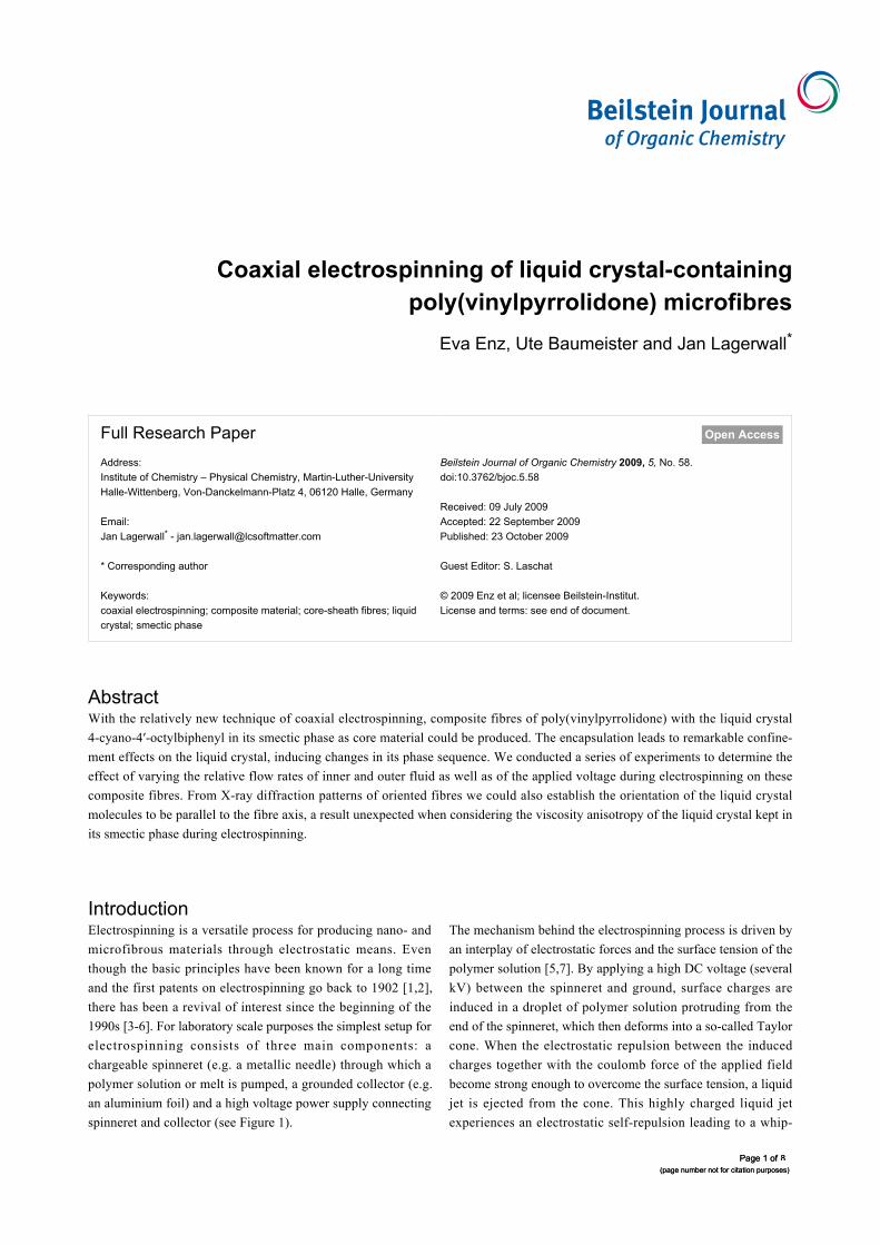
Figure 1: Schematic illustration of the main parts of the setup used inour lab for coaxial electrospinning and of the resulting compositefibres.
ping motion and stretching process on its way to the collector,
the latter leading to a dramatic reduction of fibre diameter.
During this process most of the solvent must be evaporated, so
that a stable, essentially dry fibre (the length of which in the
ideal case is determined only by the time spinning is continued)
is collected on a target substrate. This collection can be made on
glass slides placed on the collector during electrospinning,
resulting in a randomly oriented, nonwoven mat. Beside this,
oriented fibres can also be achieved by modification of the
target, e.g. by using two parallel electrodes as collector [8]. A
recent review on different electrospinning setup designs is given
in [9].
The morphology and final diameter of the resulting fibres can
be influenced by several parameters, which can be divided into
two categories: intrinsic properties of the polymer solution, and
operational conditions. The most important are: type of polymer
and its concentration; viscosity, electrical conductivity, polarity
and surface tension of the solvent; applied electric field,
distance between spinneret and collector, flow rate of the
polymer solution and also the humidity and temperature of the
surroundings, since they influence the evaporation of the
solvent.
An interesting variation of electrospinning is the use of a spin-
neret comprising two coaxial capillaries, allowing two different
liquids to be spun, one inside the other, leading to a composite
fibre with core–sheath structure [10-12]. Recently it could be
shown that also a room temperature nematic liquid crystal (LC)
can be coaxially spun with a composite sheath of TiO2 and
poly(vinylpyrrolidone) (PVP) [13]. Such composite fibres with
a core exhibiting the responsiveness and special properties (in
particular optical) that result from the unique combination of
fluidity and long-range order of liquid crystals are interesting
from different points of view. On the one hand, the LC can give
the fibre new functionality, in particular sensitivity to tempera-
ture variations or to the application of electric and/or magnetic
fields, on the other the strong confinement that can be achieved
by the process can affect the LC phase sequence [14]. Electro-
spinning offers a cheap and simple way of studying such
confinement effects systematically.
In this work we present our results on composites of PVP as
sheath and the liquid crystal 4-cyano-4′-octylbiphenyl (8CB) as
core produced by coaxial electrospinning. The latter LC
exhibits a smectic phase (phase sequence: cryst. 20.5 SmA 32.0
N 39.2 iso.) in contrast to the LC used in our previous work,
which formed only a nematic liquid crystal phase. After some
general remarks on the properties of these composites, we show
in the first part a systematic study on fibres with different
content of LC core. Secondly we studied the influence of the
magnitude of the applied voltage on the fibres. Finally we show
X-ray investigations on these materials and discuss the orienta-
tion of the LC based on these results.
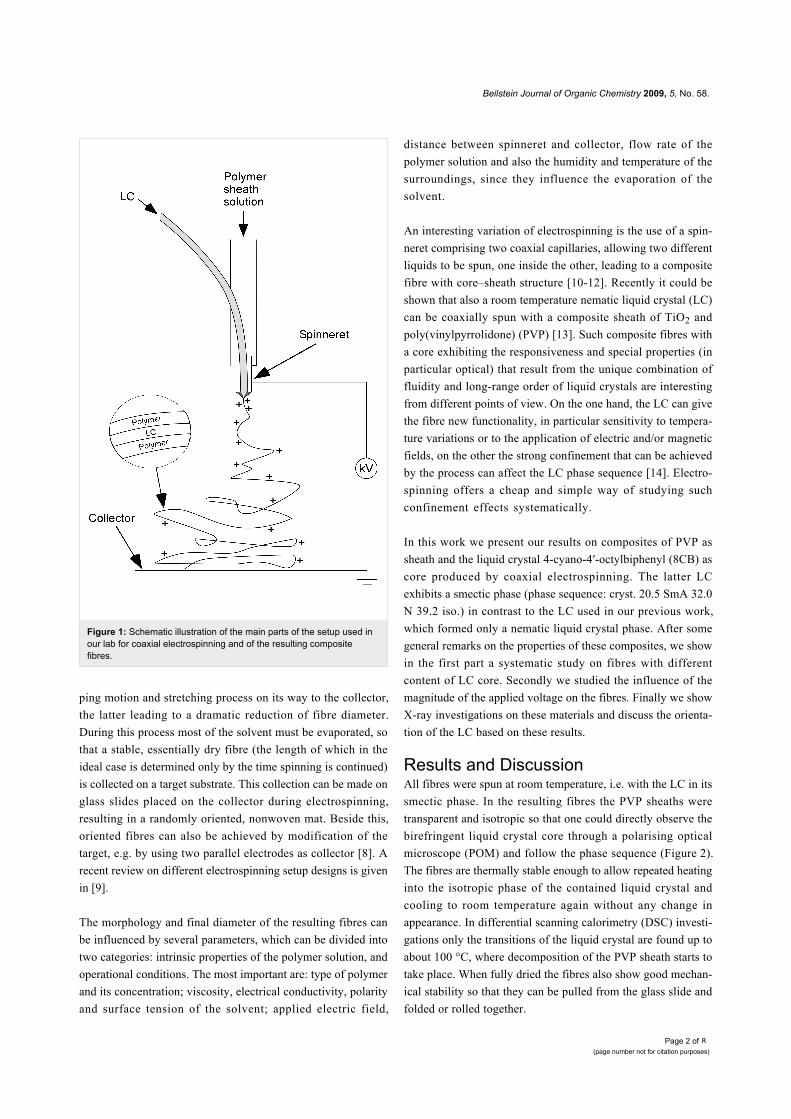
Results and DiscussionAll fibres were spun at room temperature, i.e. with the LC in its
smectic phase. In the resulting fibres the PVP sheaths were
transparent and isotropic so that one could directly observe the
birefringent liquid crystal core through a polarising optical
microscope (POM) and follow the phase sequence (Figure 2).
The fibres are thermally stable enough to allow repeated heating
into the isotropic phase of the contained liquid crystal and
cooling to room temperature again without any change in
appearance. In differential scanning calorimetry (DSC) investi-
gations only the transitions of the liquid crystal are found up to
about 100 °C, where decomposition of the PVP sheath starts to
take place. When fully dried the fibres also show good mechan-
ical stability so that they can be pulled from the glass slide and
folded or rolled together.
Beilstein Journal of Organic Chemistry 2009, 5, No. 58.
Page 3 of(page number not for citation purposes)
8
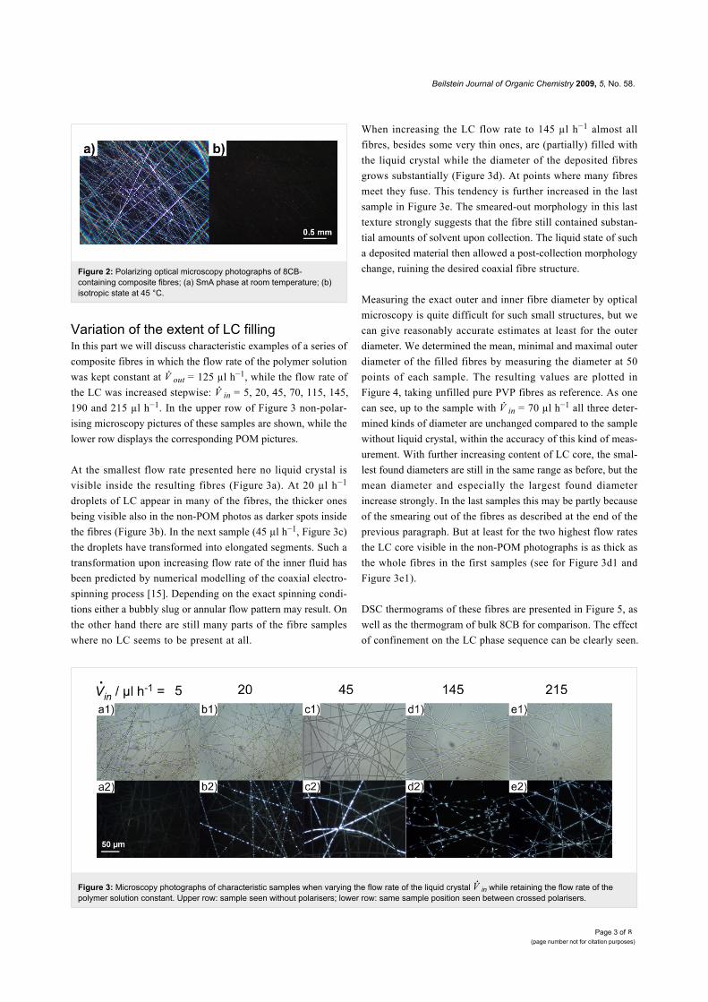
Figure 3: Microscopy photographs of characteristic samples when varying the flow rate of the liquid crystal in while retaining the flow rate of thepolymer solution constant. Upper row: sample seen without polarisers; lower row: same sample position seen between crossed polarisers.
Figure 2: Polarizing optical microscopy photographs of 8CB-containing composite fibres; (a) SmA phase at room temperature; (b)isotropic state at 45 °C.
Variation of the extent of LC fillingIn this part we will discuss characteristic examples of a series of
composite fibres in which the flow rate of the polymer solution
was kept constant at out = 125 µl h−1, while the flow rate of
the LC was increased stepwise: in = 5, 20, 45, 70, 115, 145,
190 and 215 µl h−1. In the upper row of Figure 3 non-polar-
ising microscopy pictures of these samples are shown, while the
lower row displays the corresponding POM pictures.
At the smallest flow rate presented here no liquid crystal is
visible inside the resulting fibres (Figure 3a). At 20 µl h−1
droplets of LC appear in many of the fibres, the thicker ones
being visible also in the non-POM photos as darker spots inside
the fibres (Figure 3b). In the next sample (45 µl h−1, Figure 3c)
the droplets have transformed into elongated segments. Such a
transformation upon increasing flow rate of the inner fluid has
been predicted by numerical modelling of the coaxial electro-
spinning process [15]. Depending on the exact spinning condi-
tions either a bubbly slug or annular flow pattern may result. On
the other hand there are still many parts of the fibre samples
where no LC seems to be present at all.
When increasing the LC flow rate to 145 µl h−1 almost all
fibres, besides some very thin ones, are (partially) filled with
the liquid crystal while the diameter of the deposited fibres
grows substantially (Figure 3d). At points where many fibres
meet they fuse. This tendency is further increased in the last
sample in Figure 3e. The smeared-out morphology in this last
texture strongly suggests that the fibre still contained substan-
tial amounts of solvent upon collection. The liquid state of such
a deposited material then allowed a post-collection morphology
change, ruining the desired coaxial fibre structure.
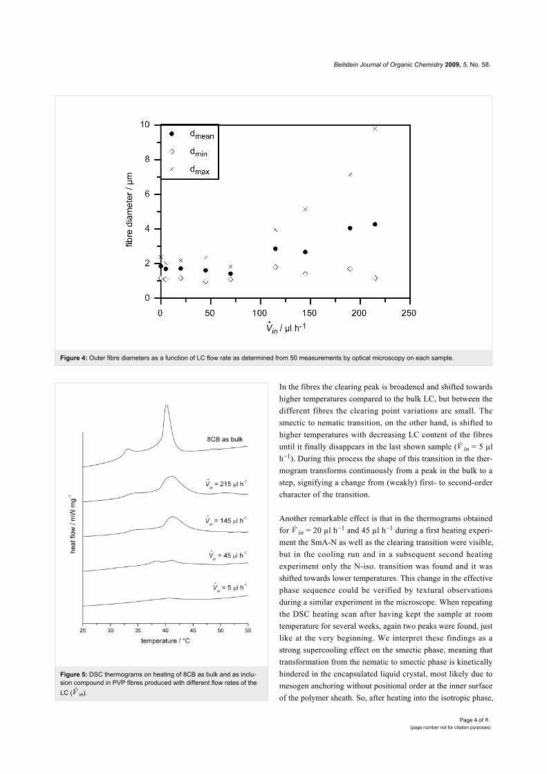
Measuring the exact outer and inner fibre diameter by optical
microscopy is quite difficult for such small structures, but we
can give reasonably accurate estimates at least for the outer
diameter. We determined the mean, minimal and maximal outer
diameter of the filled fibres by measuring the diameter at 50
points of each sample. The resulting values are plotted in
Figure 4, taking unfilled pure PVP fibres as reference. As one
can see, up to the sample with in = 70 µl h−1 all three deter-
mined kinds of diameter are unchanged compared to the sample
without liquid crystal, within the accuracy of this kind of meas-
urement. With further increasing content of LC core, the smal-
lest found diameters are still in the same range as before, but the
mean diameter and especially the largest found diameter
increase strongly. In the last samples this may be partly because
of the smearing out of the fibres as described at the end of the
previous paragraph. But at least for the two highest flow rates
the LC core visible in the non-POM photographs is as thick as
the whole fibres in the first samples (see for Figure 3d1 and
Figure 3e1).
DSC thermograms of these fibres are presented in Figure 5, as
well as the thermogram of bulk 8CB for comparison. The effect
of confinement on the LC phase sequence can be clearly seen.
Beilstein Journal of Organic Chemistry 2009, 5, No. 58.
Page 4 of(page number not for citation purposes)
8
Figure 4: Outer fibre diameters as a function of LC flow rate as determined from 50 measurements by optical microscopy on each sample.
Figure 5: DSC thermograms on heating of 8CB as bulk and as inclu-sion compound in PVP fibres produced with different flow rates of theLC ( in).
In the fibres the clearing peak is broadened and shifted towards
higher temperatures compared to the bulk LC, but between the
different fibres the clearing point variations are small. The
smectic to nematic transition, on the other hand, is shifted to
higher temperatures with decreasing LC content of the fibres
until it finally disappears in the last shown sample ( in = 5 µl
h−1). During this process the shape of this transition in the ther-
mogram transforms continuously from a peak in the bulk to a
step, signifying a change from (weakly) first- to second-order
character of the transition.
Another remarkable effect is that in the thermograms obtained
for in = 20 µl h−1 and 45 µl h−1 during a first heating experi-
ment the SmA-N as well as the clearing transition were visible,
but in the cooling run and in a subsequent second heating
experiment only the N-iso. transition was found and it was
shifted towards lower temperatures. This change in the effective
phase sequence could be verified by textural observations
during a similar experiment in the microscope. When repeating
the DSC heating scan after having kept the sample at room
temperature for several weeks, again two peaks were found, just
like at the very beginning. We interpret these findings as a
strong supercooling effect on the smectic phase, meaning that
transformation from the nematic to smectic phase is kinetically
hindered in the encapsulated liquid crystal, most likely due to
mesogen anchoring without positional order at the inner surface
of the polymer sheath. So, after heating into the isotropic phase,
Beilstein Journal of Organic Chemistry 2009, 5, No. 58.
Page 5 of(page number not for citation purposes)
8
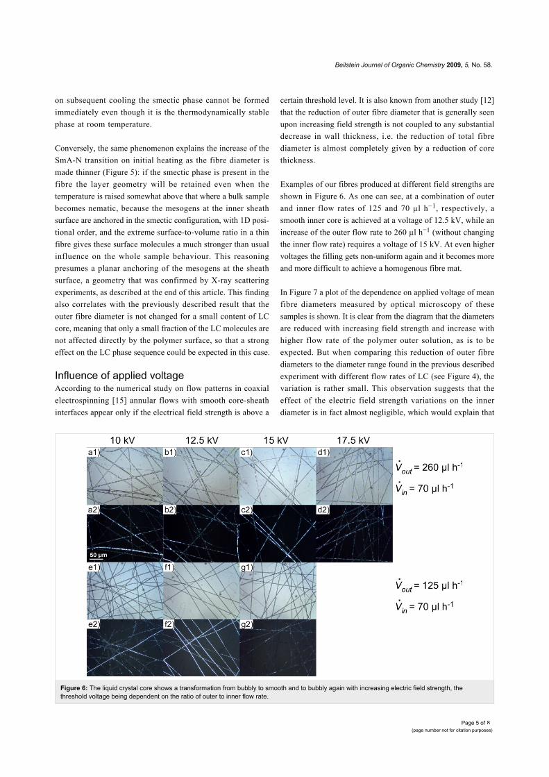
Figure 6: The liquid crystal core shows a transformation from bubbly to smooth and to bubbly again with increasing electric field strength, thethreshold voltage being dependent on the ratio of outer to inner flow rate.
on subsequent cooling the smectic phase cannot be formed
immediately even though it is the thermodynamically stable
phase at room temperature.
Conversely, the same phenomenon explains the increase of the
SmA-N transition on initial heating as the fibre diameter is
made thinner (Figure 5): if the smectic phase is present in the
fibre the layer geometry will be retained even when the
temperature is raised somewhat above that where a bulk sample
becomes nematic, because the mesogens at the inner sheath
surface are anchored in the smectic configuration, with 1D posi-
tional order, and the extreme surface-to-volume ratio in a thin
fibre gives these surface molecules a much stronger than usual
influence on the whole sample behaviour. This reasoning
presumes a planar anchoring of the mesogens at the sheath
surface, a geometry that was confirmed by X-ray scattering
experiments, as described at the end of this article. This finding
also correlates with the previously described result that the
outer fibre diameter is not changed for a small content of LC
core, meaning that only a small fraction of the LC molecules are
not affected directly by the polymer surface, so that a strong
effect on the LC phase sequence could be expected in this case.
Influence of applied voltageAccording to the numerical study on flow patterns in coaxial
electrospinning [15] annular flows with smooth core-sheath
interfaces appear only if the electrical field strength is above a
certain threshold level. It is also known from another study [12]
that the reduction of outer fibre diameter that is generally seen
upon increasing field strength is not coupled to any substantial
decrease in wall thickness, i.e. the reduction of total fibre
diameter is almost completely given by a reduction of core
thickness.
Examples of our fibres produced at different field strengths are
shown in Figure 6. As one can see, at a combination of outer
and inner flow rates of 125 and 70 µl h−1, respectively, a
smooth inner core is achieved at a voltage of 12.5 kV, while an
increase of the outer flow rate to 260 µl h−1 (without changing
the inner flow rate) requires a voltage of 15 kV. At even higher
voltages the filling gets non-uniform again and it becomes more
and more difficult to achieve a homogenous fibre mat.
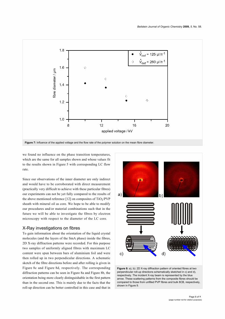
In Figure 7 a plot of the dependence on applied voltage of mean
fibre diameters measured by optical microscopy of these
samples is shown. It is clear from the diagram that the diameters
are reduced with increasing field strength and increase with
higher flow rate of the polymer outer solution, as is to be
expected. But when comparing this reduction of outer fibre
diameters to the diameter range found in the previous described
experiment with different flow rates of LC (see Figure 4), the
variation is rather small. This observation suggests that the
effect of the electric field strength variations on the inner
diameter is in fact almost negligible, which would explain that
Beilstein Journal of Organic Chemistry 2009, 5, No. 58.
Page 6 of(page number not for citation purposes)
8
Figure 7: Influence of the applied voltage and the flow rate of the polymer solution on the mean fibre diameter.
we found no influence on the phase transition temperatures,
which are the same for all samples shown and whose values fit
to the results shown in Figure 5 with corresponding LC flow
rate.
Since our observations of the inner diameter are only indirect
and would have to be corroborated with direct measurement
(practically very difficult to achieve with these particular fibres)
our experiments can not be yet fully compared to the results of
the above mentioned reference [12] on composites of TiO2/PVP
sheath with mineral oil as core. We hope to be able to modify
our procedures and/or material combinations such that in the
future we will be able to investigate the fibres by electron
microscopy with respect to the diameter of the LC core.
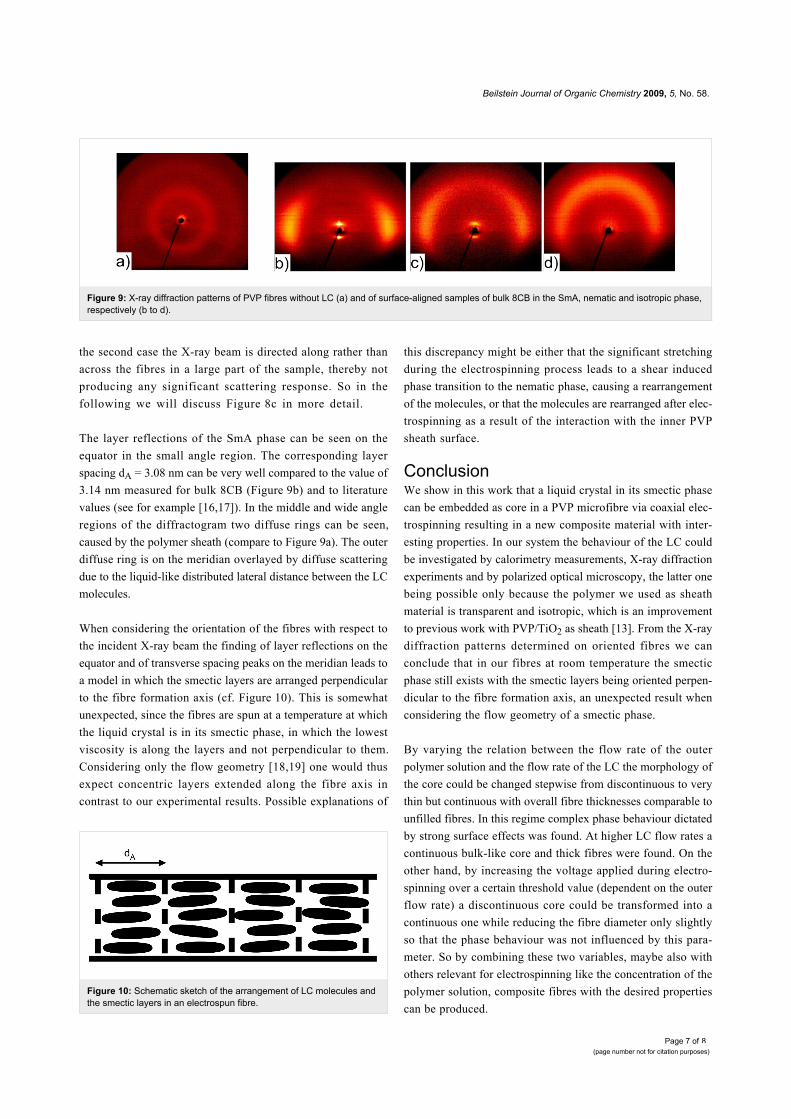
X-Ray investigations on fibresTo gain information about the orientation of the liquid crystal
molecules (and the layers of the SmA phase) inside the fibres,
2D X-ray diffraction patterns were recorded. For this purpose
two samples of uniformly aligned fibres with maximum LC
content were spun between bars of aluminium foil and were
then rolled up in two perpendicular directions. A schematic
sketch of the fibre directions before and after rolling is given in
Figure 8c and Figure 8d, respectively. The corresponding
diffraction patterns can be seen in Figure 8a and Figure 8b, the
orientation being more clearly distinguishable in the first pattern
than in the second one. This is mainly due to the facts that the
roll-up direction can be better controlled in this case and that in
Figure 8: a), b): 2D X-ray diffraction pattern of oriented fibres at twoperpendicular roll-up directions schematically sketched in c) and d),respectively. The incident X-ray beam is represented by the bluearrow. These scattering patterns from the composite fibres should becompared to those from unfilled PVP fibres and bulk 8CB, respectively,shown in Figure 9.
Beilstein Journal of Organic Chemistry 2009, 5, No. 58.
Page 7 of(page number not for citation purposes)
8
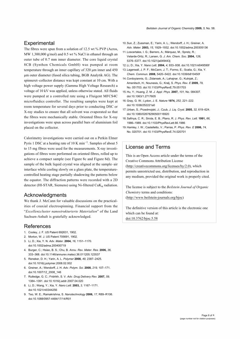
Figure 9: X-ray diffraction patterns of PVP fibres without LC (a) and of surface-aligned samples of bulk 8CB in the SmA, nematic and isotropic phase,respectively (b to d).
Figure 10: Schematic sketch of the arrangement of LC molecules andthe smectic layers in an electrospun fibre.
the second case the X-ray beam is directed along rather than
across the fibres in a large part of the sample, thereby not
producing any significant scattering response. So in the
following we will discuss Figure 8c in more detail.
The layer reflections of the SmA phase can be seen on the
equator in the small angle region. The corresponding layer
spacing dA = 3.08 nm can be very well compared to the value of
3.14 nm measured for bulk 8CB (Figure 9b) and to literature
values (see for example [16,17]). In the middle and wide angle
regions of the diffractogram two diffuse rings can be seen,
caused by the polymer sheath (compare to Figure 9a). The outer
diffuse ring is on the meridian overlayed by diffuse scattering
due to the liquid-like distributed lateral distance between the LC
molecules.
When considering the orientation of the fibres with respect to
the incident X-ray beam the finding of layer reflections on the
equator and of transverse spacing peaks on the meridian leads to
a model in which the smectic layers are arranged perpendicular
to the fibre formation axis (cf. Figure 10). This is somewhat
unexpected, since the fibres are spun at a temperature at which
the liquid crystal is in its smectic phase, in which the lowest
viscosity is along the layers and not perpendicular to them.
Considering only the flow geometry [18,19] one would thus
expect concentric layers extended along the fibre axis in
contrast to our experimental results. Possible explanations of
this discrepancy might be either that the significant stretching
during the electrospinning process leads to a shear induced
phase transition to the nematic phase, causing a rearrangement
of the molecules, or that the molecules are rearranged after elec-
trospinning as a result of the interaction with the inner PVP
sheath surface.
ConclusionWe show in this work that a liquid crystal in its smectic phase
can be embedded as core in a PVP microfibre via coaxial elec-
trospinning resulting in a new composite material with inter-
esting properties. In our system the behaviour of the LC could
be investigated by calorimetry measurements, X-ray diffraction
experiments and by polarized optical microscopy, the latter one
being possible only because the polymer we used as sheath
material is transparent and isotropic, which is an improvement
to previous work with PVP/TiO2 as sheath [13]. From the X-ray
diffraction patterns determined on oriented fibres we can
conclude that in our fibres at room temperature the smectic
phase still exists with the smectic layers being oriented perpen-
dicular to the fibre formation axis, an unexpected result when
considering the flow geometry of a smectic phase.
By varying the relation between the flow rate of the outer
polymer solution and the flow rate of the LC the morphology of
the core could be changed stepwise from discontinuous to very
thin but continuous with overall fibre thicknesses comparable to
unfilled fibres. In this regime complex phase behaviour dictated
by strong surface effects was found. At higher LC flow rates a
continuous bulk-like core and thick fibres were found. On the
other hand, by increasing the voltage applied during electro-
spinning over a certain threshold value (dependent on the outer
flow rate) a discontinuous core could be transformed into a
continuous one while reducing the fibre diameter only slightly
so that the phase behaviour was not influenced by this para-
meter. So by combining these two variables, maybe also with
others relevant for electrospinning like the concentration of the
polymer solution, composite fibres with the desired properties
can be produced.
Beilstein Journal of Organic Chemistry 2009, 5, No. 58.
Page 8 of(page number not for citation purposes)
8
ExperimentalThe fibres were spun from a solution of 12.5 wt % PVP (Acros,
MW 1,300,000 g/mol) and 0.5 wt % NaCl in ethanol through an
outer tube of 0.7 mm inner diameter. The core liquid crystal
8CB (Synthon Chemicals GmbH) was pumped at room
temperature through an inner capillary of 320 μm inner and 450
μm outer diameter (fused silica tubing, BGB Analytik AG). The
spinneret–collector distance was kept constant at 10 cm. With a
high voltage power supply (Gamma High Voltage Research) a
voltage of 10 kV was applied, unless otherwise stated. All fluids
were pumped at a controlled rate using a Fluigent MFCS4C
microfluidics controller. The resulting samples were kept at
room temperature for several days prior to conducting DSC or
X-ray studies to ensure that all solvent was evaporated so that
the fibres were mechanically stable. Oriented fibres for X-ray
investigations were spun across parallel bars of aluminium foil
placed on the collector.
Calorimetry investigations were carried out on a Perkin Elmer
Pyris 1 DSC at a heating rate of 10 K min−1. Samples of about 5
to 15 mg fibres were used for the measurements. X-ray investi-
gations of fibres were performed on oriented fibres, rolled up to
achieve a compact sample (see Figure 8c and Figure 8d). The
sample of the bulk liquid crystal was aligned at the sample–air
interface while cooling slowly on a glass plate, the temperature-
controlled heating stage partially shadowing the patterns below
the equator. The diffraction patterns were recorded with a 2D
detector (HI-STAR, Siemens) using Ni-filtered CuKα radiation.
AcknowledgmentsWe thank J. McCann for valuable discussions on the practical-
ities of coaxial electrospinning. Financial support from the
“Excellenzcluster nanostrukturierte Materialien” of the Land
Sachsen-Anhalt is gratefully acknowledged.
References1. Cooley, J. F. US Patent 692631, 1902.2. Morton, W. J. US Patent 705691, 1902.3. Li, D.; Xia, Y. N. Adv. Mater. 2004, 16, 1151–1170.
doi:10.1002/adma.2004007194. Burger, C.; Hsiao, B. S.; Chu, B. Annu. Rev. Mater. Res. 2006, 36,
333–368. doi:10.1146/annurev.matsci.36.011205.1235375. Reneker, D. H.; Yarin, A. L. Polymer 2008, 49, 2387–2425.
doi:10.1016/j.polymer.2008.02.0026. Greiner, A.; Wendorff, J. H. Adv. Polym. Sci. 2008, 219, 107–171.
doi:10.1007/12_2008_1467. Rutledge, G. C.; Fridrikh, S. V. Adv. Drug Delivery Rev. 2007, 59,
1384–1391. doi:10.1016/j.addr.2007.04.0208. Li, D.; Wang, Y.; Xia, Y. Nano Lett. 2003, 3, 1167–1171.
doi:10.1021/nl03442569. Teo, W. E.; Ramakrishna, S. Nanotechnology 2006, 17, R89–R106.
doi:10.1088/0957-4484/17/14/R01
10. Sun, Z.; Zussman, E.; Yarin, A. L.; Wendorff, J. H.; Greiner, A.Adv. Mater. 2003, 15, 1929–1932. doi:10.1002/adma.200305136
11. Loscertales, I. G.; Barrero, A.; Márquez, M.; Spretz, R.;Velarde-Ortiz, R.; Larsen, G. J. Am. Chem. Soc. 2004, 126,5376–5377. doi:10.1021/ja049443j
12. Li, D.; Xia, Y. Nano Lett. 2004, 4, 933–938. doi:10.1021/nl049590f13. Lagerwall, J. P. F.; McCann, J. T.; Formo, E.; Scalia, G.; Xia, Y.
Chem. Commun. 2008, 5420–5422. doi:10.1039/b810450f14. Cordoyiannis, G.; Zidansek, A.; Lahajnar, G.; Kutnjak, Z.;
Amenitsch, H.; Nounesis, G.; Kralj, S. Phys. Rev. E 2009, 79,No. 051703. doi:10.1103/PhysRevE.79.051703
15. Hu, Y.; Huang, Z. M. J. Appl. Phys. 2007, 101, No. 084307.doi:10.1063/1.2717605
16. Gray, G. W.; Lydon, J. E. Nature 1974, 252, 221–222.doi:10.1038/252221a0
17. Urban, S.; Przedmojski, J.; Czub, J. Liq. Cryst. 2005, 32, 619–624.doi:10.1080/02678290500116920
18. Safinya, C. R.; Sirota, E. B.; Plano, R. J. Phys. Rev. Lett. 1991, 66,1986–1989. doi:10.1103/PhysRevLett.66.1986
19. Hamley, I. W.; Castelletto, V.; Parras, P. Phys. Rev. E 2006, 74,No. 020701. doi:10.1103/PhysRevE.74.020701
License and TermsThis is an Open Access article under the terms of the
Creative Commons Attribution License
(http://creativecommons.org/licenses/by/2.0), which
permits unrestricted use, distribution, and reproduction in
any medium, provided the original work is properly cited.
The license is subject to the Beilstein Journal of Organic
Chemistry terms and conditions:
(http://www.beilstein-journals.org/bjoc)
The definitive version of this article is the electronic one
which can be found at:
doi:10.3762/bjoc.5.58