Biomimicry via Electrospinning
22
This article was downloaded by: [Tsinghua University] On: 07 June 2012, At: 17:31 Publisher: Taylor & Francis Informa Ltd Registered in England and Wales Registered Number: 1072954 Registered office: Mortimer House, 37-41 Mortimer Street, London W1T 3JH, UK Critical Reviews in Solid State and Materials Sciences Publication details, including instructions for authors and subscription information: http://www.tandfonline.com/loi/bsms20 Biomimicry via Electrospinning Jinyou Lin a b c , Xianfeng Wang a b c , Bin Ding a b , Jianyong Yu b , Gang Sun c & Moran Wang d e a State Key Laboratory for Modification of Chemical Fibers and Polymer Materials, College of Materials Science and Engineering, Donghua University, Shanghai, China b Nanomaterials Research Center, Research Institute of Donghua University, Shanghai, China c College of Textiles, Donghua University, Shanghai, China d School of Aerospace, Tsinghua University, Beijing, China e Earth and Environmental Sciences Division, Los Alamos National Laboratory, Los Alamos, New Mexico, USA Available online: 07 Jun 2012 To cite this article: Jinyou Lin, Xianfeng Wang, Bin Ding, Jianyong Yu, Gang Sun & Moran Wang (2012): Biomimicry via Electrospinning, Critical Reviews in Solid State and Materials Sciences, 37:2, 94-114 To link to this article: http://dx.doi.org/10.1080/10408436.2011.627096 PLEASE SCROLL DOWN FOR ARTICLE Full terms and conditions of use: http://www.tandfonline.com/page/terms-and-conditions This article may be used for research, teaching, and private study purposes. Any substantial or systematic reproduction, redistribution, reselling, loan, sub-licensing, systematic supply, or distribution in any form to anyone is expressly forbidden. The publisher does not give any warranty express or implied or make any representation that the contents will be complete or accurate or up to date. The accuracy of any instructions, formulae, and drug doses should be independently verified with primary sources. The publisher shall not be liable for any loss, actions, claims, proceedings, demand, or costs or damages whatsoever or howsoever caused arising directly or indirectly in connection with or arising out of the use of this material.
Transcript of Biomimicry via Electrospinning

This article was downloaded by: [Tsinghua University]On: 07 June 2012, At: 17:31Publisher: Taylor & FrancisInforma Ltd Registered in England and Wales Registered Number: 1072954 Registered office: Mortimer House,37-41 Mortimer Street, London W1T 3JH, UK
Critical Reviews in Solid State and Materials SciencesPublication details, including instructions for authors and subscription information:http://www.tandfonline.com/loi/bsms20
Biomimicry via ElectrospinningJinyou Lin a b c , Xianfeng Wang a b c , Bin Ding a b , Jianyong Yu b , Gang Sun c & Moran Wangd ea State Key Laboratory for Modification of Chemical Fibers and Polymer Materials, College ofMaterials Science and Engineering, Donghua University, Shanghai, Chinab Nanomaterials Research Center, Research Institute of Donghua University, Shanghai, Chinac College of Textiles, Donghua University, Shanghai, Chinad School of Aerospace, Tsinghua University, Beijing, Chinae Earth and Environmental Sciences Division, Los Alamos National Laboratory, Los Alamos,New Mexico, USA
Available online: 07 Jun 2012
To cite this article: Jinyou Lin, Xianfeng Wang, Bin Ding, Jianyong Yu, Gang Sun & Moran Wang (2012): Biomimicry viaElectrospinning, Critical Reviews in Solid State and Materials Sciences, 37:2, 94-114
To link to this article: http://dx.doi.org/10.1080/10408436.2011.627096
PLEASE SCROLL DOWN FOR ARTICLE
Full terms and conditions of use: http://www.tandfonline.com/page/terms-and-conditions
This article may be used for research, teaching, and private study purposes. Any substantial or systematicreproduction, redistribution, reselling, loan, sub-licensing, systematic supply, or distribution in any form toanyone is expressly forbidden.
The publisher does not give any warranty express or implied or make any representation that the contentswill be complete or accurate or up to date. The accuracy of any instructions, formulae, and drug doses shouldbe independently verified with primary sources. The publisher shall not be liable for any loss, actions, claims,proceedings, demand, or costs or damages whatsoever or howsoever caused arising directly or indirectly inconnection with or arising out of the use of this material.

Critical Reviews in Solid State and Materials Sciences, 37:94–114, 2012Copyright c© Taylor and Francis Group, LLCISSN: 1040-8436 print / 1547-6561 onlineDOI: 10.1080/10408436.2011.627096
Biomimicry via Electrospinning
Jinyou Lin,1,2,3 Xianfeng Wang,1,2,3 Bin Ding,1,2,∗ Jianyong Yu,2 Gang Sun,3
and Moran Wang4,5,∗∗1State Key Laboratory for Modification of Chemical Fibers and Polymer Materials, College of MaterialsScience and Engineering, Donghua University, Shanghai, China2Nanomaterials Research Center, Research Institute of Donghua University, Shanghai, China3College of Textiles, Donghua University, Shanghai, China4School of Aerospace, Tsinghua University, Beijing, China5Earth and Environmental Sciences Division, Los Alamos National Laboratory, Los Alamos,New Mexico, USA
Electrospinning, an efficient technique to produce long fibers with micro- or nanoscale diam-eters, has attracted tremendous interests during past decades. By orchestrating parametersin electrospinning, diverse forms of fibrous assemblies and individual fibers with hierarchicalstructures can be successfully achieved. Some of these versatile micro- and nanostructuresdisplay a remarkable resemblance to the materials and objects existing in nature, such as hon-eycomb, spider webs, extracellular matrix, plant tendril and leaf, etc. The emerging field ofbiomimicry enables one to mimic biology or nature to develop novel nanomaterials as well as toimprove processes for materials via electrospinning. In this review, we present a full panoramaof recent studies on biomimicry via electrospinning, and highlight some of biomimicked one-dimensional nanomaterials as well as their functions and applications to date.
Keywords electrospinning, biomimicry, biomimetics, electrospun fibers, hierarchical structures
Table of Contents
1. INTRODUCTION ................................................................................................................................................95
2. ELECTROSPINNING TECHNOLOGY—AN OVERVIEW .................................................................................952.1. History of Electrospinning ..............................................................................................................................952.2. Processing of Electrospinning ..........................................................................................................................96
3. BIOMIMETIC PROCESS VIA ELECTROSPINNING ........................................................................................97
4. BIOMIMICRY VIA MANIPULATING FIBER ASSEMBLIES ............................................................................984.1. Bamboo Leaf .................................................................................................................................................994.2. Feather ..........................................................................................................................................................994.3. Honeycomb ................................................................................................................................................. 1004.4. Extracellular Matrix ..................................................................................................................................... 101
5. BIOMIMICRY VIA MANIPULATING INDIVIDUAL FIBER STRUCTURES .................................................. 1025.1. Lotus Leaf ................................................................................................................................................... 1025.2. Silver Ragwort Leaf ..................................................................................................................................... 103
∗E-mail: [email protected]∗∗E-mail: [email protected]
94
Dow
nloa
ded
by [
Tsi
nghu
a U
nive
rsity
] at
17:
31 0
7 Ju
ne 2
012

BIOMIMICRY VIA ELECTROSPINNING 95
5.3. Plant Tendril ................................................................................................................................................ 1045.4. Soap-Bubble and Spider Web ........................................................................................................................ 1065.5. Polar Bear Hair ............................................................................................................................................ 108
6. APPLICATIONS INSPIRED FROM NATURE .................................................................................................. 1106.1. Self-Cleaning Materials ................................................................................................................................ 1106.2. Tissue Engineering ....................................................................................................................................... 1106.3. Sensors ........................................................................................................................................................ 1106.4. Catalysis and Others ..................................................................................................................................... 110
7. SUMMARY ........................................................................................................................................................ 110
ACKNOWLEDGMENTS .......................................................................................................................................... 111
REFERENCES ......................................................................................................................................................... 111
1. INTRODUCTIONAfter billions of years’ stringent evolution and natural se-
lection, nature has developed some materials and objects thatare endowed with fascinating structures with unique propertiesand functions, such as high strength, self-cleaning, structuralcolors, thermal insulation, dry adhesion and so on.1,2 The un-derstanding of these properties created by nature may give usnew insights into the imitation and production of new materi-als and processes. For instance, the idea of fishing nets mayhave originated from spider webs; the robust hexagonal honey-comb may have led to its applications in lightweight structuresin airplane.3 Copying, adaptation or derivation from biologyis referred to as ‘biomimicry.’4 The term ‘biomimetics’ intro-duced by Schmitt in 1969,5 and originates from the Greek wordbiomimesis.6 Biomimetics can be defined as the investigationof the formation, structure or function of biologically producedsubstances and materials and biological mechanisms and pro-cesses especially for the purpose of synthesizing similar prod-ucts by artificial mechanisms which mimic natural ones.7 Theemerging field of biomimetics allows human to mimic nature toexploit nanomaterials, nanodevices, and processes which pro-vide desirable properties.7
Diverse features found in nature’s objects are on thenanoscale. The major focus on nanoscience and nanotechnologysince the early 1990s has provided a significant impetus in mim-icking nature using nanofabrication techniques for commercialapplications.1,4 As an increasing hot nanofabrication technique,electrospinning has emerged as a versatile and cost-effectivemethod for producing long continuous fibers with diametersranging from several micrometers down to a few nanometers byapplying a high voltage on a polymer solution or melt.8–10 Formany reasons, electrospinning provides unique opportunities toemulate nature. From the name “spinning,” we can imagine apicture in which a spider is spinning its web. The differencemay lie in that the electrospinning is induced by the uniqueelectrical power. Thus we can draw an incipient conclusionthat the process of electrospinning is biomimetic (details will
be discussed in Section 3). Additionally, the building blocksof natural polymer-based nanofibrous membranes at the lowestlevel of hierarchy (nano to micro) are organic fibers, and manyof these are natural. Furthermore, like many natural functionalsurfaces, the large surface area of electrospun fibrous mem-branes offers tremendous opportunities to functionalize them.3
More importantly, electrospun materials exhibit various fasci-nating morphologies such as bead-on-string, ribbon-like, heli-cal, porous, necklace-like, firecracker shape, rice-grain shape,core-shell, multi-channel tubular, multi-core cable-like, tube-in-tube, nanowire-in-microtube, and hollow structures.8 All ofthese attributes lend electrospun fibers more to biomimetic con-cepts compared with other fibers.
This review will focus on the recent developments onbiomimicry via electrospinning, particularly on bio-inspiredelectrospun nanomaterials as well as their functions and appli-cations. The major part of this review is organized into five sec-tions. In Section 2, we give an overview about electrospinningtechnology. A brief summary of the bio-inspired electrospinningprocess is shown in Section 3. Sections 4 and 5 present a compre-hensive overview on manipulating fiber structures inspired bynature. Some potential applications associated with biomimicryare highlighted in Section 6. Finally, we provide conclusionsabout this review and also present personal prospects on thefuture of this topic.
2. ELECTROSPINNING TECHNOLOGY—AN OVERVIEW
2.1. History of ElectrospinningElectrospinning, also known as electrostatic spinning, is con-
sidered as a variant of the electrostatic spraying process whichwas first found by Bose in 1745.10 The first devices to sprayliquids through the application of an electrical charge werealready patented by Cooley and Morton at the beginning ofthe 20th century.11–13 In 1914, Zeleny reported that the finefiber-like liquid jets could be emitted from a charged liquiddroplet in the presence of an electrical potential, which is
Dow
nloa
ded
by [
Tsi
nghu
a U
nive
rsity
] at
17:
31 0
7 Ju
ne 2
012

96 J. LIN ET AL.
FIG. 1. Formhals’ experimental apparatus for producing arti-ficial filaments via electrospinning: (A) spinning solutions arepassed into electrical field formed between two electrodes com-posed of (B) a slender rotating serrated wheel in a pool and (C)a wheel as a collector. The artificial filaments (D) are continu-ously removed and collected from the rotating collector. (Colorfigure available online.)
considered to be the origin of principle for the modern needleelectrospinning.14,15 In 1934, a crucial patent, revealing the ex-perimental apparatus for the practical production of artificialfilaments using electrical field (Figure 1), was issued for thefirst time by Formhals.16 Later on, a series of patents were is-sued,17–19 which focused on improvements and modifications onthe electrospinning apparatus. In the 1960s, Taylor worked outthe instability criteria of spherical liquid droplets subjected toan external electrostatic field.20,21 Significantly, he obtained thecharacteristic value of the cone’s semi-vertical angle at 49.3o,which was also referred as the “Taylor cone.” Then, others ap-plied this work on a wide variety of polymeric systems in prepar-ing electrospun fibers.22–24
Despite these early discoveries, electrospinning did not ob-tain substantial attention until the booming of nanotechnologyin the 1990s. Several research groups, especially the Reneker’sgroup, revived electrospinning by demonstrating the fabrica-tion of ultra-thin fibers from various polymers.25,26 Initializedby the Reneker group, the popularity of electrospinning hasincreased exponentially in the past decade as clearly reflectedfrom the variation of publication numbers in this filed (Figure 2).Through further investigation of these publications, we can sum-marize that the development of electrospinning in the recent 10years are featured in the following six aspects:27 (i) extensivelyincreased varieties of polymers and composites; (ii) compre-hensive understanding of the formation of electrospun fibers;(iii) highly designed structures of electrospun fibers inspiredfrom nature; (iv) the booming of multi-components and inor-ganic fibers; (v) the transfer of research focus from fabricationto applications including tissue engineering, filtration, cataly-sis, self-cleaning, drug delivery system, sensors, dye-sensitizedsolar cells (DSSCs), etc.; (vi) large-scaled production of elec-trospun fibers by modified electrospinning equipments for com-mercial use.
2001 2002 2003 2004 2005 2006 2007 2008 2009 2010 20110
200
400
600
800
1000
1200
1400
Num
ber
of P
ubli
cati
ons
Year
FIG. 2. Schematic representation of the annual number of publi-cations on electrospinning or electrospun during the past decade,following the ISI Web of Knowledge. For 2011, there are already1046 publications before July 15.
2.2. Processing of ElectrospinningIn general, a typical electrospinning setup usually consists of
three major components (Figure 3a), i.e., a high voltage powersupply, a spinneret (a metal needle usually connected with sy-ringe controlled by syringe pump), and a grounded target (as acollector).28 During electrospinning, the high voltage was ap-plied to the polymer solution, the suspended liquid droplet at theneedle tip was highly electrified and the induced charges wereeventually distributed over the surfaces. The charged droplet willbe subjected to the electrostatic forces into a conical shape.9
When the applied voltage surpasses the critical value, a thinpolymer jet is ejected from the tip of the Taylor cone. The jetfollows a direct path towards the grounded target for a very shortdistance from its origin and reaches a bending instability point,and then the jet begins to whip, as shown in Figure 3a. Thecharged jet undergoes bending instability combined with sol-vent evaporation and jet solidification, forming a long and thinfiber in a form of non-woven fabric.29–31 Additionally, the so-called electrospinning process is closely related to the utilizedsolution. The ejected jet may break into small droplets or parti-cles due to the Rayleigh instability as a result of low viscosityof solution,32 which results in the formation of beads-on-stringfibers or even micro-spheres. Meanwhile, with an increase of thesolution concentration, the resultant fibers are bead-free with auniform diameter (Figure 3b).
The morphologies and diameters of electrospun fibers aregoverned by the parameters during electrospinning, which in-clude the solution parameters, the processing parameters, andthe environmental parameters.33 The effects of these parameterson as-spun fibers are summarized succinctly as follows.
Generally, a lower polymer concentration leads to a lower liq-uid viscosity. Whereas, the fibers become thicker with uniformdiameter if more concentrate solutions are used (Figure 3b).34
For a given concentration, lowering the surface tension of spin-ning solution favors the formation of continuous fibers with
Dow
nloa
ded
by [
Tsi
nghu
a U
nive
rsity
] at
17:
31 0
7 Ju
ne 2
012

BIOMIMICRY VIA ELECTROSPINNING 97
FIG. 3. (a) Schematic illustration of the typical setup for elec-trospinning. (b) (Scanning electron microscope) SEM imagesof the electrospun polystyrene (PS) fibers formed from differentpolymer concentration. (Reprinted with permission from Linet al.34 Copyright 2010: American Chemical Society.) (Colorfigure available online.)
fewer beads.35 Polymer with a higher molecular weight canbe electrospun into continuous and bead-free fibers at a rela-tively lower concentration, and meanwhile, a high concentra-tion is necessary for forming uniform fibers.33,36 The conduc-tivity of a solution increases by adding salts, the fiber diameterscan be effectively reduced as well as the number of beads.35,37
The solvent volatility affects the rate of solvent removal fromthe fluid jet, as well as the phase separation and solidificationof the jet. High-volatility solvents are easy to form a porous-surface morphology.38 Meanwhile, the surface morphology ofresultant fibers can also be manipulated by tuning the ratio ofsolvent mixtures.34,39
Sufficiently high electrical field strength is an essential con-dition for electrospinning. When a stable jet ejects from Taylor
cone, an increase of the electrical field strength will enable theTaylor cone retreat into spinneret. Meanwhile, the number ofbeads will dramatically increase and the distribution of fiberdiameters will become much wider.40,41 Whether the fiber di-ameters increase or decrease with the electrical field strengthdepends on the solvent system in electrospinning. Additionally,increasing the electrical field strength can raise the productivityof the resultant fibers. A higher solution flow rate will lead tothicker fibers for a concentrate polymers solution; otherwise,more beads will be formed in the resultant fibrous mats.36,41
If the working distance is too short, the jet will deposit on thetarget before dry, resulting in adhesion among the fibers.42 Fur-thermore, the effect of working distance on the fiber diametersis closely related to the solution properties.
Usually, electrospinning is conducted at the room tempera-ture in air. When the environmental temperature rises, the con-ductivity of solution increases while the viscosity and the surfacetension decrease. This enables some polymers that failed to beelectrospun at the room temperature to be able to be electro-spun into fibers.43,44 For a solution composed of water-solublepolymer and solvent miscible with vapor in air, increasing therelative humidity will lead to the formation of more beads, andin some cases the fibers are adhered to each other due to theresidual solvent.45,46 If the hydrophobic polymer is dissolvedin some organic solvent with a high volatility, increasing therelative humidity will increase the number of nano-pores on thefiber surfaces, and for some cases the fiber interior is highlyporous due to vapor induced phase separation.47,48
3. BIOMIMETIC PROCESS VIA ELECTROSPINNINGIn nature, spiders and silk worms can spin continuous fibers
by passing aqueous liquid crystalline protein solution throughtheir spinnerets.49 The resultant fibers exhibit remarkably highstrength and toughness, which has attracted tremendous inter-ests of scientists in various disciplines for a long time to tracethe mechanism of silk processing in insects and spiders andto produce the high-performance fibers resembling spider silkfiber. Interestingly, many attempts to make synthetic fibers mim-icking the native silk resulted in the successful production andcommercialization of some polyamide materials such as Kevlarand Nylon, which exhibited a comparable strength but a lowertoughness to the dragline silk.50
Inspired by native spider silk, many methods have been usedto spin the artificial spider silk including the conventional wet-spinning of the regenerated dragline silk and reconstituted B.mori silk protein and analogue, however, the comprehensiveunderstanding of the molecular processes occurring during spin-ning of protein fibers and the investigation of how the spinningconditions to affect the properties of final material have not beenfully work-out.3 Furthermore, it is a mystery that the native silkfibers can be produced with a minimal force by spiders, unlikethe man-made fibers formed from its spin solution required avery high pressure or a large drawing force.51
Dow
nloa
ded
by [
Tsi
nghu
a U
nive
rsity
] at
17:
31 0
7 Ju
ne 2
012

98 J. LIN ET AL.
FIG. 4. (a) Spider-spinning process. (b) The experimental setup of the aerated-solution electrospinning. (c) SEM image of thetypical resultant fibers. (Reprinted with permission from He et al.51 Copyright 2008: Elsevier.) (Color figure available online.)
Recently, researchers have revealed that all spiders have silk-producing spinnerets at the end of the abdomen consisting ofa great number of nanoscale tubes (Figure 4a), the spin solu-tion can be extruded out and form a bubble at the apex of eachtube.51,52 He et al.51 confirmed that the surface tension of eachbubble was so small such that it could be spun into nanofiberswith an awfully small force, either by the spider’s body weight ortension created by the rear legs. To mimic this mysterious spin-ning process, they developed a new spinning system (also knownas bubble-electrospinning) to produce nanofibers by ejectingpolymer jets from the bubble formed from the highly chargedaerated polymer solution (Figure 4b). The mechanism of thisspinning process can be described as that the charges accumu-lated on the bubble surfaces formed from the aerated solution inthe presence of an electric field, and a fluid jet ejected from theapex of the conical bubble once the electric field exceeds a criti-cal value needed to overcome the surface tension, subsequently,the jet solidified into nanofiber. Additionally, the minimum di-ameter of nanofiber produced by this process can reach as smallas 50 nm (Figure 4c).51 This strategy successfully biomimickedthe spider spinning process and overcame some shortcomingsof traditional electrospinning such as strongly dependent on thesolution viscosity.
4. BIOMIMICRY VIA MANIPULATING FIBERASSEMBLIESIn general, the electrospun fibers are deposited on a target in
the form of non-woven fibrous mats, which consists of randomlyoriented micro- and/or nanofibers, as shown in Figure 3b. Thistypical assembly structure of electrospun fibers can be attributedto the jet instability in unique electrospinning process. In the pastfew years, a great number of novel electrospinning equipmentswith improved designs or additional setups, such as using a ro-tating cylinder or disc, two parallel electrodes separated by a gapas collector,53–55 introducing insulators to grounded collector toinfluence the fiber deposited position,56 adding an assistant mag-netic field to alter the fiber trajectory in the spinning process,57,58
have been well developed to alter the resultant fiber assembledstructures to obtain the designed fibrous mats with expectedstructures and functionalities. The controllable fibers deposi-tion endows their assembly with periodic structures exhibit-ing some unique properties, which broadens the applications ofelectrospun fibrous mats. Recently, many fascinating structuresfrom nanoscale to macroscale existing in nature have been suc-cessfully mimicked via electrospinning technique. Some typi-cally biomimetic structures will be fully discussed as follows.In this section, we will introduce the recent progress in the
Dow
nloa
ded
by [
Tsi
nghu
a U
nive
rsity
] at
17:
31 0
7 Ju
ne 2
012

BIOMIMICRY VIA ELECTROSPINNING 99
design of biomimetic electrospun fiber assemblies inspired bynature.
4.1. Bamboo LeafIn nature, some plant leaves are anisotropic surface pattern-
ing, such as the natural rice leaf, the lotus leaf margin, and thebamboo leaf,59–61 resulting in different surface wettability in twodirections of these surfaces. Figure 5b shows a water dropletplaced on the surface of a bamboo leaf.61 The water dropletdisplayed an ellipsoidal shape rather than spherical, reflectingthe anisotropic property of the bamboo leaf surface. To mimicthe native surface, Wu et al.61 prepared aligned poly(vinyl bu-tyral) (PVB) fibrous mats by utilizing a modified collector (i.e.,
FIG. 5. (a) A digital photograph of the aligned fibers collectedbetween two parallel electrodes. A water droplet set on thesurface of (b) a bamboo leaf, (c) a silicon wafer coated byaligned electrospun PVB nanofibers. (d) SEM image of alignedPVB nanofibers. (e) AFM image of the fiber array. (Reprinted bypermission from Wu et al.61 Copyright 2008: The Royal Societyof Chemistry.) (Color figure available online.)
two parallel conductive copper strip electrodes separated with asmall gap). The resultant fibers were stretched to span across thegap and aligned uniaxially in relatively large areas due to the re-distribution of the electric field of the modified collector (Figure5a). Figure 5c displays a water droplet placed on the biomimeticsurface of assembled fiber arrays transferred from collector, andthe water droplet exhibits a very similar shape to that on the bam-boo leaf. The observation by SEM and atomic force microscopy(AFM) is shown in Figures 5d and 5e, respectively, revealing themicro- and nanostructrures of the biomimetic surface.61 Benefitfrom this easy and fast fabrication method, aligned electrospunnanofibers provide a new platform to realize functional surfaceswith desired wetting properties on a large scale.
4.2. FeatherIn addition to the plant leaves, other examples of anisotropy
were also found including the pigeon feather, the goose feather,and the duck feather.61–63 Figure 6 provides the detailed mor-phology of the pigeon feather and its hydrophobicity.62 Figure6a depicts that the feather was separated into two symmetricparts by rachis with a diameter at about 110 µm, and the barbs(about 20 µm) sent forth from rachis with a slant angle about 30◦
paralleling to each other. The corresponding high-magnificationSEM image reveals that there are many barbules (about 5 µm)sent forth from the barbs slantly as shown in Figure 6b. This fas-cinatingly hierarchical structure contributs to high water contactangles (WCAs) of the pigeon feather (Figure 6b, inset).
Besides pigeon feather, some other waterfowl feathers alsohave special surfaces with anisotropic wetting properties. Wuet al.61 studied the WCAs of the goose feather and found that thecontact angles viewed in all three directions were different fromeach other (Figure 7b). This multi-direction anisotropic wettingproperty was ascribed to the dissymmetry of the microstruc-ture pattern which was very similar with the structure of thepigeon feather. To obtain the fibrous membrane with a feather-like structure, a typical fiber collector was designed by Wu et al.as described in Figure 8a, consisting of a spiculate metal needleperpendicularly with a rectilinear metal strip.61 The electrospunPVB nanofibers presented a fan-shaped radiating nanofiber pat-tern with a similar microstructure to a goose feather. The waterdroplet placed on the artificial surface exhibiting a streamlinedshape was depicted in Figure 7c, indicating that the fibrous mem-brane with an anisotropic wettability in multiple directions wassuccessfully mimicked via altering the nanofibers orientation.
According to the concept of re-entrant geometry proposed byMcKinley and Cohen’s groups,63 many natural surfaces, suchas various bird feathers and plant leaves, inherently possess re-entrant surface texture, which enables them to support a compos-ite interface with water and thereby exhibit superhydrophobic-ity. Inspired by re-entrant structured duck feather, they demon-strated the fabrication of re-entrant beads-on-string structuredmembranes by modifying electrospun polymethyl methacrylatefibrous membranes using polyhedral oligomeric silsesquioxane.
Dow
nloa
ded
by [
Tsi
nghu
a U
nive
rsity
] at
17:
31 0
7 Ju
ne 2
012

100 J. LIN ET AL.
FIG. 6. (a) SEM image of the central part of a feather. (b) SEM image of the pigeon feather structure, inset showed the water dropplaced on the edge of the cut feather. (Reprinted with permission from Bormashenko et al.62 Copyright 2007: Elsevier.) (Colorfigure available online.)
The concept of re-entrant geometry especial relative to fibrousmaterials help us further understand the connection between theparameters of the models and the measurable experiment for thecases of various fibrous structures.64
FIG. 7. (a) Digital photograph of fan-shaped radiating nanofiberpattern collected by a spiculate copper needle perpendicular toa rectilinear copper strip. A water droplet set on the surfaceof (b) goose feather, (c) fan-shaped radiating nanofiber pat-tern. (Reprinted with permission from Wu et al.61 Copyright2008: The Royal Society of Chemistry.) (Color figure availableonline.)
4.3. HoneycombA honeycomb, presented in Figure 8, is composed of hexag-
onal wax cells constructed by honeybees in their nests to pro-tect their larvae and store honey and pollen. The honeycombconsists of many hexagons due to the hexagon tiles the planewith minimal perimeter per piece area.65 This typical structurehas advantages to adapt nature selection. Alternatively, the term,honeycomb, is also used for man-made materials that resemble itin appearance or structure. Many researches have confirmed thatthe honeycomb composite materials made of paper, graphite, oraluminum can significantly reduce their weight of componentsof cars, planes, and spacecraft with little sacrifice in strength.66
Self-assembly technique has been used to arrange small com-ponents, especially nanoscale objects, into ordered systems oraggregates with desired structures such as monolayers, superlat-tices, tubes, and honeycomb micro-porous films very easily ata comparatively low cost.67 In recent years, controlling of elec-trospun fibers assembled into desired micro- and/or nanostruc-tures have received increasing attentions, for electrospun fiberswith ordered microstructures and patterns may have specific
FIG. 8. Photograph of honeycomb. (Reprinted with permissionfrom Kellex. Copyright 2011: Droid Life: A Droid CommunityBlog.) (Color figure available online.)
Dow
nloa
ded
by [
Tsi
nghu
a U
nive
rsity
] at
17:
31 0
7 Ju
ne 2
012

BIOMIMICRY VIA ELECTROSPINNING 101
FIG. 9. (a) Schematic of the electrospinning setup. SEM images showing the surface morphology and wall structure of thehoneycomb-patterned nanofibrous structures of PVA, PEO and PAN electrospun at different conditions: (b) PVA, concentration6%, 22 kV, on plastic films; (c) PEO, concentration 3%, 22 kV, on Al substrates; (d) PEO, concentration 16%, 19 kV, on Alsubstrates; (d) PAN, concentration 16%, 19 kV, on Al substrates; (f) PAN, concentration 2%, 22 kV, on Al substrates. (Reprintedwith permission from Yan et al.68 Copyright 2011: American Chemical Society.)
functions in numerous applications including microelectronic,photonic, and biomedical applications.56
Yan et al.68 reported the fabrication of honeycomb-patternednanofibrous structures through well-controlled self-assembly ofcontinuous electrospun polymer nanofibers. They used electro-spinning to produce charged polymer nanofibers, which werekept in the liquid state when landing on the substrates, by ap-propriately controlling the electrospinning conditions. Figure 9ashows the modified electrospinning setup for assembling elec-trospun fibers they utilized, and the substrates placed at an an-gular distance from needle nozzle is to avoid the droplet at alow concentration dripping on the fibrous mats damaging thesamples. During electrospinning, these charged wet nanofiberswere self-assembled into the honeycomb patterned nanofibrousstructures driven by the competitive actions of surface tensionand electrostatic repulsion. Several kinds of polymers (e.g.,
poly(vinyl alcohol) (PVA), poly(ethylene oxide) (PEO) andpolyacrylonitrile (PAN)) were electrospun into nanofibers andassembled into honeycomb-like structures as shown in Figures9b to 9f, indicating that self-assembling electrospun nanofiberswith honeycomb structures is a general phenomenon and appli-cable to many spinnable polymers.
4.4. Extracellular MatrixFortunately, the alignments of electrospun fibers have been
extensively investigated by researchers,53–55 which enables thefibrous mats composed of nanofibers with anisotropic prop-erty in two directions easily to be prepared. More interest-ingly, the composition of electrospun fibrous mats can be ad-justed via blending polymer solutions,69,70 adding additives intopolymer solutions,71 post-treatments,72,73 as well as multi-jets
Dow
nloa
ded
by [
Tsi
nghu
a U
nive
rsity
] at
17:
31 0
7 Ju
ne 2
012

102 J. LIN ET AL.
spinning of different polymer solutions.74,75 Therefore, not onlythe structures of electrospun fibrous mats can be controlled viaelectrospinning but also the composition of resultant fibers areadjustable, which makes the electrospinning technique as a goodcandidate for production of materials inspired from nature.
The natural extracellular matrices (ECM), which are com-posed of various protein fibrils and fibers interwoven within ahydrated network of glycosaminoglycan chains, mainly consistof three major types of biomolecules: (i) structural proteins,such as collagen and elastin, (ii) specialized proteins includingfibrillin, fibronectin and laminin, and (iii) proteoglycans.76 A lotof cells can organize their ECM with nanofibrous structural unitswhich ranged from a few tens of nanometers to about a hun-dred of nanometers. The chemical compositions and biologicalaspects of such a hierarchically structured cellular environmentaffect the functions of cells and tissue profoundly, which canbe mimicked by manipulating electrospun biodegradable andbiocompatible polymer nanofibers with designed hierarchicalstructures and typical compositions.77
Over the past decade, a variety of natural (e.g., collagen,fibrinogen, elastin, etc.) and synthetic (e.g., poly(glycolic acid)(PGA), poly(lactic acid) (PLA), polycaprolactone (PCL), etc.)polymers have been electrospun into nanofibers in the form ofnonwoven fibrous mats with three-dimensional (3D) hierarchi-cal structures to mimic the ECM in bodies.78 Researchers havedemonstrated that the cells displayed a positive response to ECMmade of electrospun collagen fibers. For instance, Matthewset al.79,80 successfully prepared the various types of electrospuncollagen fibers (e.g., I, II, and III) from HFP and found thatthe cells could propagate after seeding onto the resultant ECM.In addition to natural polymers, electrospun PGA, PLA, PCLand their copolymers fibrous mats also showed a good affinityto cells as good candidates for ECM to culture the cells. Forexample, Mo et al.81 reported a biomimetic ECM comprisingelectrospun poly(L-lactide-co-ε-caprolactone) with L-lactide toε-caprolactone ratio of 75 to 25 fibers for smooth muscle cellsand endothelial cell proliferations, and the result indicated thatthe two kinds of cells adhered and proliferated well on the as-prepared ECM.
The bone system offers structures to the live body, protectsinternal organs and acts as a reservoir of calcium and phosphate.However, the fracture of bones and large bone defects owing tovarious traumas or natural ageing are typical types of tissue mal-function, which is still a challenge to regenerate for orthopaedicsurgeons.78,82 Fortunately, surface modification of electrospunfibers with ligands for specific cell receptors and ECM pro-teins, such as gelatin and calcium phosphate calcium phosphatelayer, can improve their bioactivity in bone tissue engineering.In order to mimic the bone ECM and to provide a friendlyinterface with the host, Li et al.72 fabricated the fibrous PCLscaffolds from via electrospinning, followed by a surface modi-fication with gelatin via a layer-by-layer method and depositionof calcium phosphate using a mild mineralization procedure.Nandakumar et al.83 developed a bone tissue engineering scaf-
fold by coating the calcium phosphate onto electrospun fibermatrices. It is worth noting that the deposition of the calciumphosphate improved the in vivo bioactivity of the polymer. Al-ternatively, the biodegradable and biocompatible polymer solu-tions with inclusion of hydroxyapatite nanocrystals can also beelectrospun into nanocompostie fibrous mats to mimic the hu-man bone matrix, which exhibits good performances for boneregeneration.71,84
5. BIOMIMICRY VIA MANIPULATING INDIVIDUALFIBER STRUCTURES
5.1. Lotus LeafPlant leaves exhibiting self-cleaning effects have received
much more interests in recent years.85 The lotus leaf isamong the most well-known and studied examples, which ex-hibits well water-repellent properties (Figure 10a). The micro-morphological characteristics of the lotus-leaf surfaces werealso extensively studied, and it has been demonstrated that thelotus leaf surface is really rough due to the so-called papil-lose epidermal cells forming papillae or micro-level mound asshown in Figure 10b. Furthermore, the high-magnification SEMimage of the papillae exhibits that its surface is also rough withnanoscale asperities comprising 3D epicuticular wax tubules(Figures 10c and 10d). The typical hierarchical structure of thesurface enables the water droplets on the surface readily to siton the apex of the micro- and/or nanostructures which trappedmore air as a cushion under the droplets by displaying a super-hydrophobicty with a WCA of about 160◦ (Figure 10e).86
Inspired by this fascinating phenomenon, researchers in thefields of science and industry have developed many methods,such as chemical deposition,87 layer-by-layer deposition,88 col-loidal assembly,89 and template-based techniques,90 to yieldartificial surfaces with the self-cleaning functionality. The fabri-cation of these artificial surfaces mainly depended on modifyinga rough surface by chemical modification with low surface en-ergy and making a rough surface from the low-surface-energymaterials. In recent years, the electrospinning technique iswidely used for producing superhydrophobic surfaces biomim-icked from nature due to the morphology, structure, and proper-ties of fibrous mats can be well and easily controlled by adjustingthe spinning solution properties, the processing parameters aswell as the ambient conditions.64
It is well known that electrospinning dilute polymer solu-tions can produce beads-on-string fibers or even polymer micro-spheres.35 The shape and morphology of resultant beads can bealso manipulated by changing the solvent compositions91,92 Inview of the versatility of electrospun fibrous mats, the artificialsurfaces with characteristics of lotus leaves can be successfullyproduced via electrospinning. To mimic the topography of lo-tus leaves and to achieve a high WCA, Jiang et al.93 fabricatedthe PS fibrous film via electrospinning dilute PS solution dis-solved in N,N-dimethyl formamide (DMF). The resultant filmis composed of porous microspheres (3 to 7 µm) and nanofibers
Dow
nloa
ded
by [
Tsi
nghu
a U
nive
rsity
] at
17:
31 0
7 Ju
ne 2
012

BIOMIMICRY VIA ELECTROSPINNING 103
FIG. 10. (a) Photograph of lotus leaf in pool. SEM images (shown at three magnifications (b)–(d)) of lotus leaf surface, whichconsists of a microstructure formed by papillose epidermal cells covered with 3D epicuticular wax tubules on the surface whichcreate nanostructure. (e) Image of a water droplet sitting on a lotus leaf. (Figures (b) to (e) reprinted with permission from Bhushanet al.86 Copyright 2009: The Royal Society.) (Color figure available online.)
(60 to 140 nm), which exhibits superhydrophobicity with aWCA greater than 160◦ as described in Figure 11. The porousmicrospheres of the resultant film play a leading role in thesuperhydrophobicity due to its hierarchical structure. Acatayet al.94 also successfully fabricated a lotus-leaf-like structuredfibrous mat with good superhydrophobicity by electrospinninga dilute polymer solution.
5.2. Silver Ragwort LeafThe silver ragwort is another plant with hydrophobic leaves.
Figure 12a shows the photograph of a silver ragwort. The plantleaves exhibit white-color which is not from any dye but re-lated with the trichomes on the leaf surfaces.95 The inset ofFigure 12a displays the hydrophobicity of a silver ragwort leaf.The SEM images of the leaf surfaces present that the leaf is
FIG. 11. (a) SEM image of porous microsphere/nanofiber composite film prepared from a 7 wt% PS/DMF solution. (b) Threedimensional network structure of the porous microsphere/nanofiber composite film. (c) Surface nanostructure of a single porousmicrosphere. (d) Water droplet on the resultant film. (Reprinted with permission from Jiang et al.93 Copyright 2004: John Wiley& Sons, Inc.)
Dow
nloa
ded
by [
Tsi
nghu
a U
nive
rsity
] at
17:
31 0
7 Ju
ne 2
012

104 J. LIN ET AL.
FIG. 12. (a) Photograph of the silver ragwort leaves. (b) and (c) SEM images of the leaf with different magnification. (Inset ofFigure (a), Figures (b) and (c) reprinted with permission from Miyauchi et al.39 Copyright 2006: IOP Publishing.) (Color figureavailable online.)
covered by a lot of curved fibers with an average diameter about5.6 µm (Figure 12b). Numerous grooves with diameters rangingfrom 100 to 200 nm are found along the fiber axis (Figure 12c).Measurements showed that the WCA on the leaf surface wasabout 147◦.31,94
In order to prepare a functional surface imitating the silverragwort, Ding et al.39 prepared PS microfibers by electrospin-ning concentrate PS solutions and adjusted the fiber surfacestructures by changing the solvent compositions. Figure 13ashows SEM images of the electrospun PS fibers formed from sol-vent mixtures of tetrahydrofuran (THF) and DMF with weightratio of 2/2. The fiber surfaces are covered with micrometre-sized oval pores along the fiber axis as shown in the inset ofFigure 13a. At the THF/DMF weight ratio of 1/3, numerousshort grooves (like elongated islands) with an average lengthof 1.43 µm and width of 158 nm along the fiber axis withoutthe appearance of oval micropores are presented on the resultantfiber surfaces (Figure 13b). The typical surface morphology wasexplained by a rapid phase separation during the electrospinningprocess.96 Measurements indicated that the resultant fiber sur-faces exhibited a surperhydrophobicity with WCAs of 157.8◦
and 159.5◦, respectively.To improve the mechanical properties of the electrospun PS
fibrous mats, Li et al.75 modified the conventional electrospin-ning setup as shown in Figure 13c. The mechanical propertyof PS fibrous mats was significantly enhanced by adding thepolyamide 6 (PA6) nanofibers homogenously into PS mats via afour-jet electrospinning process. Figures 13d and 13e show theSEM images of the blended fibrous mats of PS/PA6 with jets ra-
tios of 1/3 and 2/2, respectively. The tensile test result indicatedthat the as-prepared blended fibrous mats at the critical jets ratioof 2/2 (PS/PA6) showed a three-times increased tensile strengthcompared with that of the pure PS fibrous mats. Meanwhile, thesuperhydrophobicity of the surface still held a WCA of 150◦.Figure 13e shows several water droplets placed on the fibrousmats.75
Inspired by the lotus and silver ragwort leaves, Lin et al.97
introduced a facile process to produce superhydrophobic matswith nano-protrusions and numerous grooves by one-step elec-trospinning of PS solutions incorporating various contents ofsilica nanoparticles as described in Figure 14. It was surpris-ingly noted that PS fibrous mats containing 14.3 wt% silicananoparticles exhibited a stable superhydrophobic state with aWCA of 157.2◦ approaching that of the lotus leaf (160◦).
5.3. Plant TendrilPlant tendril is a long, tender, soft, curly, flexible and thread-
like specialized stem. Once the tendril catches an object, it willcurl into spirals or twist into a helix, often of one handednessover half of its length and of the opposite handedness over theother half, the two halves being connected by a short straightsection, depending on whether they are supported at just one endor supported at both ends, respectively.98 The circumnutation ofplant tendril allows the plant to find support or attachment, whichis of great use to the climbing plant.98,99 Figure 15 displays theplant tendrils grow in nature forming helices and spirals.
Dow
nloa
ded
by [
Tsi
nghu
a U
nive
rsity
] at
17:
31 0
7 Ju
ne 2
012

BIOMIMICRY VIA ELECTROSPINNING 105
FIG. 13. SEM images of the electrospun PS fibers formed from various weight ratios of THF/DMF in solvent: (a) 2/2 and (b) 1/3.(c) Schematic of modified electrospinning setup for multi-jets electrospinning. SEM images of fibrous mats formed with variousnumber ratios of jets of PS/PA6: (d) 3/1 and (e) 2/2. (f) Several water droplets placed on the fibrous mats formed with the numberratio of jets of 2/2 (PS/PA6) showing the superhydrophobicity. (Figures (a) and (b) reprinted with permission from Miyauchi etal.39 Copyright 2006: IOP Publishing. Figures (c) to (f) reprinted with permission from Li et al.75 Copyright 2009: AmericanChemical Society.) (Color figure available online.)
Inspired by the plant tendril, researchers found that thenanofibers with micro- and nanoscale helical structures ex-hibit some unique properties such as a much higher porosity,a good flexibility which enables them as good candidates forpotential applications in areas comparing sensors, transduc-ers, resonators, advanced optical components, and drug deliverysystems.100 To date, stable helices of porous manganese oxidematerials have been produced from the contraction of a sol-gel upon solvent evaporation.101 Nanoscale helical structures ofzinc oxide and silicon dioxide were also generated by the vaporprocessing methods.102,103
More recently, electrospinning has been proved to an ef-ficient and simple method to fabricate the helical nanofibers.For the electrospinning solution, two polymers with differentproperties such as different conductivities, and different elastic-ities are usually utilized. Figures 16a and 16b show the fluores-cence microscopy images of poly(p-phenylene vinylene) (PPV)/polyvinyl pyrolidone (PVP) composite fibers that were preparedby electrospinning from PPV precursor/PVP in ethanol/DMF
followed by thermal conversion at different spinning voltage.Additionally, the authors also investigated the factors affectingthe formation of helices and provided a possible mechanism forits formation.104 Kessick et al.100 reported that microscale heli-cal fibers could be electrospun from the nonconducting poly-mer PEO and the conducting polymer poly(aniline sulfonicacid). The results suggested that the helical microcoils werespontaneously produced on a conducting substrate due to theviscoelastic contraction of a linear fiber upon partial chargeneutralization. Moreover, Shin et al.105 reported the formation ofpure helical nanofibers by electrospinning poly(2-acrylamido-2-methyl-1-propanesulfonic acid) (PAMPS) dissolved in a mix-ture of water and ethyl alcohol (Figures 16c and 16d), whichindicated that the helical fibers can also be generated from asingle nonconducting polymer. This result demonstrated thatthe physical forces caused by the bending instability of the jetin electrospinning had a greater influence on the formation ofhelical structures than the effects of the electrical charge.105 Asimilar phenomenon was also observed by Han et al.,106 and the
Dow
nloa
ded
by [
Tsi
nghu
a U
nive
rsity
] at
17:
31 0
7 Ju
ne 2
012

106 J. LIN ET AL.
FIG. 14. Biomimetic superhydrophobic surfaces from a combination of the lotus leaf and silver ragwort leaf were fabricatedvia electrospinning PS solution with silica nanoparticles. (Reprinted by permission from Lin et al.97 Copyright 2011: The RoyalSociety of Chemistry.) (Color figure available online.)
SEM images of resultant helical fibers were provided in Figures16e and 16f.
The helical nanofibers resembling plant tendrils can also beeasily produced by modifying the conventional electrospinningsetup. For example, Lin et al.107 developed a novel microfluidicelectrospinning nozzle for co-electrospinning two polymer so-lutions side-by-side. Their investigation indicated that the side-by-side bi-component fiber can be bent to one side, formingcrimped or helical fiber morphology, if the double-componentsides have a differential shrinkage. By using this method, helicalnanofibers have been successfully obtained when the fibers are
electrospun from an elastomeric polymer, polyurethane, and athermoplastic polymer, PAN.107
5.4. Soap-Bubble and Spider WebIt is well known that the morphology and diameter of elec-
trospun fibers can be adjusted by tuning the solution properties,processing parameters as well as the ambient conditions.9,28 Inthe past decade, great efforts have been made to decrease the di-ameter of electrospun fibers because the large average diameterof common electrospun fibers limits their further applications
FIG. 15. (a) Passiflora edulis tendrils and cellulosic fibers form helices and spirals. Note the helix reversals–“perversions”–indicatedby arrows in (a) and (c). Tendrils and fibers, if supported at both ends, twist into a helix of one handedness over half of its length andof the opposite handedness over the other half, the two halves being connected by a perversion. If supported at just one end, theycurl into spirals (b) and (d). (Reprinted by permission from Godinho et al.99 Copyright 2010: The Royal Society of Chemistry.)(Color figure available online.)
Dow
nloa
ded
by [
Tsi
nghu
a U
nive
rsity
] at
17:
31 0
7 Ju
ne 2
012
BIOMIMICRY VIA ELECTROSPINNING 107
FIG. 16. Fluorescence microscopy images of PPV/PVP fibers that were prepared by electrospinning from PPV precursor/PVP inethanol/DMF (a) under 7.5 kV and (b) 15 kV. SEM image showing (c) PAMPS helically structured nanofibers with regular-shapedcoils and (d) crossed helical nanofibers deposited on an aluminum collector without the introduction of subelectrodes. (Reprintedwith permission from Xin et al.104 and Shin et al.105 Copyright 2006: American Institute of Physics.) Optical micrographs ofbuckled bending electrospun (e) PEO fibers and (f) PA6 fibers. (Reprinted with permission from Han et al.106 Copyright 2007:Elsevier.) (Color figure available online.)
in ultra-filtration, ultra-sensitive sensors, catalysts, etc.108 How-ever, the objective of large-scale production of nanofibers withsmall diameter (<50 nm) via the conventional electrospinningwas rarely achieved. In recent years, net-like structured mem-branes containing interlinked nanowires with a diameter lessthan 50 nm have been identified, which was first reported byDing et al.45 They obtained the PA6 and poly(acrylic acid) (PAA)nano-nets, and concluded that the nano-nets can be controlledby adjusting the solution properties and several parameters inthe process of electrospinning.
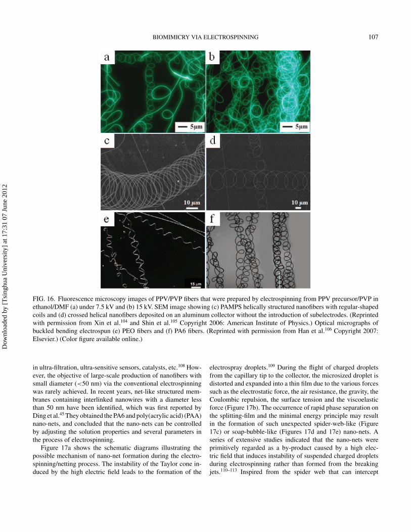
Figure 17a shows the schematic diagrams illustrating thepossible mechanism of nano-net formation during the electro-spinning/netting process. The instability of the Taylor cone in-duced by the high electric field leads to the formation of the
electrospray droplets.109 During the flight of charged dropletsfrom the capillary tip to the collector, the microsized droplet isdistorted and expanded into a thin film due to the various forcessuch as the electrostatic force, the air resistance, the gravity, theCoulombic repulsion, the surface tension and the viscoelasticforce (Figure 17b). The occurrence of rapid phase separation onthe splitting-film and the minimal energy principle may resultin the formation of such unexpected spider-web-like (Figure17c) or soap-bubble-like (Figures 17d and 17e) nano-nets. Aseries of extensive studies indicated that the nano-nets wereprimitively regarded as a by-product caused by a high elec-tric field that induces instability of suspended charged dropletsduring electrospinning rather than formed from the breakingjets.110–113 Inspired from the spider web that can intercept
Dow
nloa
ded
by [
Tsi
nghu
a U
nive
rsity
] at
17:
31 0
7 Ju
ne 2
012

108 J. LIN ET AL.
FIG. 17. Schematic diagrams illustrating the possible mechanism of nano-net formation during electrospinning/electro-nettingprocess (a) and the forces acting on the charged droplet (b). (c) Typical FE-SEM image of gelatin/NaCl nano-nets. The inset is theoptical image of spider-web. (Reprinted with permission from Wang et al.113 Copyright 2011: Elsevier.) (d) Photograph of soapbubbles. (e) Soap-bubble-like structured PAA nano-nets. (Reprinted by permission from Yang et al.111 Copyright 2011: The RoyalSociety of Chemistry.) (Color figure available online.)
insects, spider-web-like nano-nets posses great potential forapplication as ultra-fine filters for the removal of particles orviruses with a size in the nanometre range.112
5.5. Polar Bear HairIn the course of evolution over billions of years, animals,
plants and insects in nature have developed more efficient so-lutions, such as self-cleaning, self-repair, energy conservation,thermal insulation, drag reduction, dry adhesion and so on, toadapt the living environment dealing with the challenges fromthe external world.3 For example, feathers of many birds arehydrophobic due to their hierarchical structures (e.g., pigeonfeather showing in Figure 6).79 Further observation exhibits thatmany feathers are of multi-channel inner structure. These typi-cal structures might reduce weight by decreasing friction withair and serve as heat-shields from intense solar radiation.114
Multi-channel inner structures were also found in polar bearhair as shown in Figure 18, which contributed excellent thermalinsulation and optical properties to the homeothermic speciesenabling them to survive in an extremely formidable polar en-vironment.115 These attractive features have inspired humans toachieve outstanding outcomes.
The 1D hollow nanomaterials such as carbon nanotubes havebeen extensively studied resulting in a broad range of impor-tant applications during the past two decades.116 In recent tenyears, electrospinning have been widely used to generate hollownanofibers using two immiscible liquids through a coaxial, two-capillary spinneret, followed by selective removal of the cores.The circular cross-sections and well controlled orientation ofhollow nanofibers prepared by this method make them particu-larly useful as nanofluidic channels as well as some other po-tential applications in catalysis, sensor, encapsulation, and drugdelivery.117,118
Dow
nloa
ded
by [
Tsi
nghu
a U
nive
rsity
] at
17:
31 0
7 Ju
ne 2
012

BIOMIMICRY VIA ELECTROSPINNING 109
FIG. 18. (a) and (b) Scanning electron micrographs of polar bear hair-transverse sections with different magnification. (Reprintedwith permission from Grojean et al.115 Copyright 1980: Optical Society of America.)
More recently, inspired by multi-channel inner structuresof polar bear hair, Zhao et al.119 developed a multi-fluidiccompound-jet electrospinning technique to fabricate biomimetichierarchical multi-channel microtubes. Figure 19a shows aschematic illustration of the experimental setup of the multi-fluidic compound-jet electrospinning, which is an example ofthree-channel tube fabrication system. It could be observed thatthe three metallic capillaries (as electrode to charge the fluidsand delivering the inner fluid) were embedded in a spinneret(for outer fluid delivering) connected with syringe. They suc-
cessfully prepared the TiO2 three-channel microtubes by us-ing a PVP/Ti(iOPr)4 sol as the outer solution and paraffin asthe inner fluidic system, followed by selective removal of thecores and the organic component. The SEM image of the crosssection of resultant fibers is shown in Figure 19c. They havealso demonstrated that the channel number of fibers could betuned by changing the configuration of the compound nozzles.Figures 19b to 19e provide the SEM images of multi-channeltubes with variable diameters and channel numbers. The insetsin each figure show the cross section illustrations of spinneret
FIG. 19. (a) Schematic illustration of the three-channel tube fabrication system. (b-f) SEM images of multi-channel tubes withvariable diameter and channel number. The inset in each figure shows the cross section illustration of spinneret that was used tofabricate the tube. The as-prepared tubes agree very well with the corresponding spinneret. Scale bars are 100 nm. (Reprinted withpermission from Zhao et al.119 Copyright 2007: American Chemical Society.) (Color figure available online.)
Dow
nloa
ded
by [
Tsi
nghu
a U
nive
rsity
] at
17:
31 0
7 Ju
ne 2
012

110 J. LIN ET AL.
used to fabricate the tube which agree well with the corre-sponding fibers. Moreover, the composition, the wall thickness,and the tube diameters can be controlled by adjusting the ex-perimental parameters. The method shows good feasibility andeffectiveness for fabrication of multi-channel nanofibers withexpectations.119,120
6. APPLICATIONS INSPIRED FROM NATUREAs discussed in the previous sections, electrospun fibers ex-
hibit some unique properties, such as large surface-volume ratio,flexibility in surface functionalities, high porosity, high gas per-meability, and small inter-fibrous pore size, which enable themas good candidates for a broad applications including tissue en-gineering, filtration, catalysis, self-cleaning, drug delivery sys-tem, sensors, DSSCs, etc.10,28 Herein, some applications of theelectrospun fibers only pertaining to biomimicked from natureare briefly discussed as follows.
6.1. Self-Cleaning MaterialsSuperhydrophobic surfaces are very important for contami-
nation prevention. Water repellency exhibits self-cleaning func-tions due to the contaminants easily removed as water rolls offon surfaces.42 Based on the fundamental principles of fabricat-ing superhydrophobic surfaces,121 the self-cleaning materialsbiomimicked from nature such as lotus leaf, silver ragwort leaf,and feathers can be efficiently generated via electrospinningtechniques including mainly two routes, i.e., electrospinning thepolymers with low surface energy (hydrophobic materials) intohierarchical architectures,39,64,93,94,97 and modifying the electro-spun fiber mats with low surface energy materials.122,123
6.2. Tissue EngineeringTissues are the platforms for regeneration comprising car-
tilage, bone, skin tissue, blood vessels, and so on. The suit-able tissue engineering needs prepared scaffolds owning similarchemical compositions, morphologies, and surface functionalgroups as the natural counterparts.60,79 Fortunately, electrospin-ning technique provides good opportunities to mimic the naturalECM for tissue growth composed of a 3D fiber network madeof various proteins with hierarchical structures from nanoscalesto macroscales, which has been well discussed in the previ-ous sections. Some published papers have thoroughly reviewedthe applications of electrospun nanofibers in varios tissues asEMC.10,82
6.3. SensorsElectrospun fibers, offering a high surface-volume ratio, are
applicable for sensitive and fast sensing as sensor materials.For example, Ding et al.124 successfully fabricated a novel gassensor by coating PAA and PVA nanofibrous membrane withfiber diameter 100 to 400 nm onto quartz crystal microbalance(QCM) by electrospinning to detect NH3. The result indicated
that nanofibrous membranes coated QCM showed much highergas sensitivity than that of continuous film with the same compo-sitions coated QCM. The sensors based on electrospun fibrousmembrane have been well developed, which was thoroughly re-viewed by Ding et al.8 More interestingly, spider-web-like nano-nets containing interlinked nanowires with ultra-thin diameterless than 50 nm have been identified via electro-netting process,whose diameter is about one order of magnitude less than that ofconventional electrospun fibers.125 Wang et al.110,112 fabricatedthe sensors based upon QCM using nano-nets as novel sensitivematerials to detect the humidity and the trimethylamine. Theresults showed that the performance of the resultant sensorscan be greatly upgraded due to the smaller fiber diameters ofnano-nets.
6.4. Catalysis and OthersIn the preceding sections, we have discussed some inor-
ganic nanofibers with novel structures biomimicked from na-ture by electrospinning combined with calcinations. The hol-low fibers with tunable inner structures provide much higherspecific surface area compared with the solid fibers, which en-able them suitable for applications in catalysis. For example,Zhan et al.118 used the long TiO2 hollow fibers with meso-porous walls prepared by the sol-gel two-capillary spinneretelectrospinning technique to decompose the methylene blue andgaseous formaldehyde. The results showed that the as-preparedTiO2 fibers had higher photocatalytic activities than the com-mercial TiO2 nanoparticles and the corresponding mesoporousTiO2 powders. Zhao et al.126 utilized the polar bear hair-inspiredmulti-channel TiO2 fibers as catalysis to degrade the gaseousacetaldehyde. The results showed that the channel structure in-creased the surface areas by 0.79%, 21.4%, and 94.2% from1 channel, 2 channels, to 3 channels, respectively, comparedwith zero-channel, and the 3 channels TiO2 fibers exhibited thehighest photocatalytic activity.126 Furthermore, the long hollowfibers can be conveniently fixed and reclaimed as good candi-dates for photocatalytic applications.
Additionally, we believed that the spider-web-like nano-netsmay be available for ultra-filtration to intercept viruses and bac-teria such as influenza A (H1N1) virus, severe acute respira-tory syndrome (SARS) virus, and Escherichia coli due to theirsmaller fiber diameters.8
7. SUMMARYElectrospinning has been experienced nearly one hundred
years since it became an available technique to generateultra-thin polymer fibers with diameters ranging from severalnanometers to a few micrometers. During the past two decades,electrospinning has aroused increasingly interests both in aca-demic research and practical applications. In this critical review,we introduced the origin of electrospinning briefly and reviewedits development track in detail, and then we described the ba-sic setup of electrospinning and discussed the manipulation of
Dow
nloa
ded
by [
Tsi
nghu
a U
nive
rsity
] at
17:
31 0
7 Ju
ne 2
012

BIOMIMICRY VIA ELECTROSPINNING 111
resultant fiber morphology via tuning the parameters duringelectrospinning.
The straightforward and easy manipulation of electrospunfibers such as their assemblies (e.g., random or aligned withdesign), individual fiber morphology (e.g., beaded-fiber, bead-free fiber, porous, core-sheath and hollow), and chemical com-positions enables this technique as an efficient way to creatematerials with micro- and/or nanostructures existing in nature,referring to “biomimetics”. As shown in recent demonstrations,the spinning process such as the spider silk can be imitated viaelectrospinning with some modifications. Because of the welltunable morphology, structures and compositions of the elec-trospun fibers, a number of fascinating structures of objects innature, including some plant leaves, feathers, honeycomb, ECM,plant tendril, soap-bubble and spider webs, polar bear hair andso on, have been successfully biomimicked via electrospinning,sometimes, with subsequent post-treatments.
The nanomaterials bio-inspired from nature via electrospin-ning showed some advantages or excellent performances in theapplications of self-cleaning materials, tissue engineering, sen-sors, catalysts, etc. These superiorities include that the self-cleaning materials can be obtained via electrospinning directlyor with some post-treatment, easily formation of ECM with thesame compositions as well as architectures of native ECM fortissue engineering, upgrading the performance of sensors dueto the much smaller diameters of nano-nets, increasing the pho-tocatalytic activities of electrospun fibers used as a catalyst. Weare expecting this review to be a bright guiding lamp for re-searchers to develop more and more bio-inspired nanomaterialswith new functionalities.
ACKNOWLEDGMENTSThis work is supported by the National Natural Science
Foundation of China (No. 50803009 and 51173022), the “111Project” (No. 111-2-04 and B07024), the Shanghai Com-mittee of Science and Technology (No. 10JC1400600), theNational Basic Research Program of China (973 Program,2011CB606103), the Innovation Program of Shanghai Munici-pal Education Commission (11ZZ59), and the “Dawn” Programof Shanghai Education Commission (10SG32).
REFERENCES1. M. A. Meyers, P. Y. Chen, A. Y. M. Lin, and Y. Seki, Biological
materials: Structure and mechanical properties, Prog. Mater Sci.,53, 1 (2008).
2. K. Liu, X. Yao, and L. Jiang, Recent developments in bio-inspiredspecial wettability, Chem. Soc. Rev., 39, 3240 (2010).
3. L. Eadie and T. K. Ghosh, Biomimicry in textiles: past, presentand potential. An over review, J. R. Soc. Interface., 8, 761 (2011).
4. A. K. Pahl, A. Bowyer, N. R. Bogatyrev, O. A. Bogatyreva, andJ. F. V. Vincent, Biomimetics: its practice and theory, J. R. Soc.Interface., 3, 471 (2006).
5. O. H. Schmitt, in Proc. 3rd Int. Biophysics Congress, Boston,p. 297 (1969).
6. B. Bhushan and Y. C. Jung, Natural and biomimetic artificialsurfaces for superhydrophobicity, self-cleaning, low adhesion,and drag reduction, Prog. Mater Sci., 56, 1 (2011).
7. B. Bhushan, Biomimetics: lessons from nature-an overview,Phil.Trans. R. Soc. A, 367, 1445 (2009).
8. B. Ding, M. R. Wang, X. F. Wang, J. Y. Yu, and G. Sun, Electro-spun nanomaterials for ultrasensitive sensors, Mater. Today, 13,16 (2010).
9. D. Li and Y. N. Xia, Electrospinning of nanofibers: Reinventingthe wheel? Adv. Mater., 16, 1151 (2004).
10. A. Greiner and J. H. Wendorff, Electrospinning: A fascinatingmethod for the preparation of ultrathin fibres, Angew. Chem. Int.Edit., 46, 5670 (2007).
11. W. J. Morton, Method of dispersing fluids, U.S. Patent No.705691(1902).
12. J. F. Cooley, Apparatus for electrically dispersing fluids, U.S.Patent No. 692631 (1902).
13. J. F. Cooley, Electrical method of dispersing fluids, U.S. PatentNo. 745276 (1903).
14. J. Zeleny, The electrical discharge from liquid points, and a hydro-static method of measuring the electric intensity at their surfaces,Phys. Rev., 3, 69 (1914).
15. J. Zeleny, Instability of electrified liquid surfaces, Phys. Rev., 10,1 (1917).
16. A. Formhals, Process and apparatus for preparing artificialthreads, U.S. Patent No. 1975504 (1934).
17. Method of and apparatus for producing fibrous or filamentarymaterial, U.S. Patent No. 2048651 (1936).
18. M. A. Formhals, Method and apperatus for the production offibers, U.S. Patent No. 2123992 (1938).
19. P. A. Formhals, Production of artifical fibers from fiber formingliquids, U.S. Patent No. 2323025 (1943).
20. D. G. Taylor, Disintegration of water drops in an electric field,Proc. R. Soc. Lond. A, 280, 383 (1964).
21. E. G. Taylor, Electrically driven jets, Proc. R. Soc. Lond. A, 313,453 (1969).
22. P. K. Baumgarten, Electrostatic spinning of acrylic microfibers,J. Colloid Interface Sci., 36, 71 (1971).
23. L. Larrando and R. S. Manley, Electrostatic fiber spinning frompolymer melts. I. Experimental observations on fiber formationand properties, J Polym Sci: Polym Phys Ed, 19, 909 (1981).
24. E. L. Larrondo and R. St John Manley, Electrostatic fiber spin-ning from polymer melts. II. Examination of the flow field inan electrically driven jet, J Polym Sci: Polym Phys Ed, 19, 921(1981).
25. J. Doshi and D. H. Reneker, Electrospinning process andapplications of electrospun fibers, J. Electrostatics, 35, 151(1995).
26. D. H. Reneker and I. Chun, Nanometre diameter fibres of polymer,produced by electrospinning, Nanotechnology, 7, 216 (1996).
27. B. Ding and J. Y. Yu, Electrospinning and nanofibers, ChinaTextile & Apparel Press, 11 (2011).
28. Z. M. Huang, Y. Z. Zhang, M. Kotaki, and S. Ramakrishna,A review on polymer nanofibers by electrospinning and theirapplications in nanocomposites, Compos. Sci. Technol., 63, 2223(2003).
29. A. F. Spivak, Y. A. Dzenis, and D. H. Reneker, A model ofsteady state jet in the electrospinning process, MeReC, 27, 37(2000).
Dow
nloa
ded
by [
Tsi
nghu
a U
nive
rsity
] at
17:
31 0
7 Ju
ne 2
012

112 J. LIN ET AL.
30. M. M. Hohman, M. Shin, G. Rutledge, and M. P. Brenner, Elec-trospinning and electrically forced jets. I. Stability theory, Phys.Fluids, 13, 2201 (2001).
31. A. L. Yarin, S. Koombhongse, and D. H. Reneker, Bending insta-bility in electrospinning of nanofibers, J. Appl. Phys., 89, 3018(2001).
32. V. Y. Shkadov and A. A. Shutov, Disintegration of a chargedviscous jet in a high electric field, Fluid Dyn. Res., 28, 23 (2001).
33. M. McKee, J. Layman, M. Cashion, and T. Long, Phospholipidnonwoven electrospun membranes, Science, 311, 353 (2006).
34. J. Y. Lin, B. Ding, J. Y. Yu, and Y. Hsieh, Direct fabrication ofhighly nanoporous polystyrene fibers via electrospinning, ACSAppl. Mater. Interfaces., 2, 521 (2010).
35. H. Fong, I. Chun, and D. H. Reneker, Beaded nanofibers formedduring electrospinning, Polymer, 40, 4585 (1999).
36. M. M. Munir, A. B. Suryamas, F. Iskandar, and K. Okuyama,Scaling law on particle-to-fiber formation during electrospinning,Polymer, 50, 4935 (2009).
37. C. Zhang, X. Yuan, L. Wu, Y. Han, and J. Sheng, Study onmorphology of electrospun poly (vinyl alcohol) mats, Eur. Polym.J., 41, 423 (2005).
38. M. Bognitzki, W. Czado, T. Frese, A. Schaper, M. Hellwig, M.Steinhart, A. Greiner, and J. H. Wendorff, Nanostructured fibersvia electrospinning, Adv. Mater., 13, 70 (2001).
39. Y. Miyauchi, B. Ding, and S. Shiratori, Fabrication of asilver-ragwort-leaf-like super-hydrophobic micro/nanoporous fi-brous mat surface by electrospinning, Nanotechnology, 17, 5151(2006).
40. J. M. Deitzel, J. Kleinmeyer, D. Harris, and N. C. B. Tan, Theeffect of processing variables on the morphology of electrospunnanofibers and textiles, Polymer, 42, 261 (2001).
41. Y. Shin, M. Hohman, M. Brenner, and G. Rutledge, Experimentalcharacterization of electrospinning: the electrically forced jet andinstabilities, Polymer, 42, 09955 (2001).
42. C. J. Buchkoa, L. C. Chena, Y. Shena, and D. C. Martina, Process-ing and microstructural characterization of porous biocompatibleprotein polymer thin films, Polymer, 40, 7397 (1999).
43. S. R. Givens, K. H. Gardner, J. F. Rabolt, and D. B. Chase, High-temperature electrospinning of polyethylene microfibers from so-lution, Macromolecules, 40, 608 (2007).
44. J. Li, A. He, J. Zheng, and C. C. Han, Gelatin andgelatin–hyaluronic acid nanofibrous membranes produced byelectrospinning of their aqueous solutions, Biomacromolecules,7, 2243 (2006).
45. B. Ding, C. R. Li, Y. Miyauchi, O. Kuwaki, and S. Shiratori,Formation of novel 2D polymer nanowebs via electrospinning,Nanotechnology, 17, 3685 (2006).
46. S. Tripatanasuwan, Z. X. Zhong, and D. H. Reneker, Effect ofevaporation and solidification of the charged jet in electrospin-ning of poly(ethylene oxide) aqueous solution, Polymer, 48, 5742(2007).
47. C. L. Casper, J. S. Stephens, N. G. Tassi, D. B. Chase, andJ. F. Rabolt, Controlling surface morphology of electrospunpolystyrene fibers: effect of humidity and molecular weight inthe electrospinning process, Macromolecules, 37, 573 (2004).
48. C. L. Pai, M. C. Boyce, and G. C. Rutledge, Morphology of porousand wrinkled fibers of polystyrene electrospun from dimethylfor-mamide, Macromolecules, 42, 2102 (2009).
49. F. Vollrath and D. P. Knight, Liquid crystalline spinning of spidersilk, Nature, 410, 541 (2001).
50. H. J. Jin and D. L. Kaplan, Mechanism of silk processing ininsects and spiders, Nature, 424, 1057 (2003).
51. J. H. He, Y. Liu, L. Xu, J. Y. Yu, and G. Sun, Biomimic fabricationof electrospun nanofibers with high-throughput, Chaos SolitonsFractals, 37, 643 (2008).
52. D. P. Knight and F. Vollrath, Spinning an elastic ribbon of spi-der silk, Philos. Trans. R. Soc. Lond. B. Biol. Sci., 357, 219(2002).
53. G. Mathew, J. P. Hong, J. M. Rhee, D. J. Leo, and C. Nah, Prepa-ration and anisotropic mechanical behavior of highly-orientedelectrospun poly(butylene terephthalate) fibers, J. Appl. Polym.Sci., 101, 2017 (2006).
54. A. Theron, E. Zussman, and A. L. Yarin, Electrostatic field-assisted alignment of electrospun nanofibres, Nanotechnology,12, 384 (2001).
55. D. Li, Y. L. Wang, and Y. N. Xia, Electrospinning of polymericand ceramic nanofibers as uniaxially aligned arrays, Nano Lett.,3, 1167 (2003).
56. D. M. Zhang and J. Chang, Patterning of electrospun fibers usingelectroconductive templates, Adv. Mater., 19, 3664 (2007).
57. J. M. Deitzel, J. D. Kleinmeyer, J. K. Hirvonen, and N. C. B. Tan,Controlled deposition of electrospun poly(ethylene oxide) fibers,Polymer, 42, 8163 (2001).
58. D. Yang, B. Lu, Y. Zhao, and X. Jiang, Fabrication of alignedfibrous arrays by magnetic electrospinning, Adv. Mater., 19, 3702(2007).
59. L. Feng, S. H. Li, Y. S. Li, H. J. Li, L. J. Zhang, J. Zhai, Y. L.Song, B. Q. Liu, L. Jiang, and D. B. Zhu, Super-hydrophobicsurfaces: From natural to artificial, Adv. Mater., 14, 1857 (2002).
60. J. Zhang, J. Wang, Y. Zhao, L. Xu, X. Gao, Y. Zheng, and L.Jiang, How does the leaf margin make the lotus surface dry as thelotus leaf floats on water?, Soft Matter, 4, 2232 (2008).
61. H. Wu, R. Zhang, Y. Sun, D. Lin, Z. Sun, W. Pan, and P. Downs,Biomimetic nanofiber patterns with controlled wettability, SoftMatter, 4, 2429 (2008).
62. E. Bormashenko, Y. Bormashenko, T. Stein, G. Whyman, andE. Bormashenko, Why do pigeon feathers repel water? Hy-drophobicity of pennae, Cassie–Baxter wetting hypothesis andCassie–Wenzel capillarity-induced wetting transition, J. ColloidInterface Sci., 311, 212 (2007).
63. A. Tuteja, W. Choi, J. M. Mabry, G. H. McKinley, and R. E.Cohen, Robust omniphobic surfaces, PNAS, 105, 18200 (2008).
64. M. Ma, R. M. Hill, and G. C. Rutledge, A review of recent resultson superhydrophobic materials based on micro- and nanofibers,J. Adhes. Sci. Technol., 22, 1799 (2008).
65. W. J. Roberts, Honeycomb geometry: Applied mathematics innature, Mathematics Teacher, 77, 188 (1984).
66. D. Mackenzie, Proving the perfection of the honeycomb, Science,285, 1338 (1999).
67. G. Widawski, M. Rawiso, and B. Francois, Self-organized hon-eycomb morphology of star-polymer polystyrene films, Nature,369, 387 (1994).
68. G. Yan, J. Yu, Y. Qiu, X. Yi, J. Lu, X. Zhou, and X. Bai,Self-assembly of electrospun polymer nanofibers: a general phe-nomenon generating honeycomb-patterned nanofibrous struc-tures, Langmuir, 27, 4285 (2011).
Dow
nloa
ded
by [
Tsi
nghu
a U
nive
rsity
] at
17:
31 0
7 Ju
ne 2
012

BIOMIMICRY VIA ELECTROSPINNING 113
69. J. Du and Y. L. Hsieh, Cellulose/chitosan hybrid nanofibersfrom electrospinning of their ester derivatives, Cellulose, 16, 247(2009).
70. K. E. Park, H. K. Kang, S. J. Lee, B. M. Min, and W. H. Park,Biomimetic nanofibrous scaffolds: Preparation and characteriza-tion of PGA/chitin blend nanofibers, Biomacromolecules, 7, 635(2006).
71. G. M. Kim, P. Simon, and J. S. Kim, Electrospun PVA/HApnanocomposite nanofibers: biomimetics of mineralized hard tis-sues at a lower level of complexity, Bioinspir. Biomim., 3, 46003(2008).
72. X. R. Li, J. W. Xie, X. Y. Yuan, and Y. N. Xia, Coating electro-spun poly(epsilon-caprolactone) fibers with gelatin and calciumphosphate and their use as biomimetic scaffolds for bone tissueengineering, Langmuir, 24, 14145 (2008).
73. F. Yang, J. G. C. Wolke, and J. A. Jansen, Biomimetic calciumphosphate coating on electrospun poly (epsilon-caprolactone)scaffolds for bone tissue engineering, Chem. Eng. J., 137, 154(2008).
74. B. Ding, E. Kimura, T. Sato, S. Fujita, and S. Shiratori, Fabricationof blend biodegradable nanofibrous nonwoven mats via multi-jetelectrospinning, Polymer, 45, 1895 (2004).
75. X. H. Li, B. Ding, J. Y. Lin, J. Y. Yu, and G. Sun, En-hanced mechanical properties of superhydrophobic microfibrouspolystyrene mats via polyamide 6 nanofibers, J. Phys. Chem. C,113, 20452 (2009).
76. M. P. Lutolf and J. A. Hubbell, Synthetic biomaterials as instruc-tive extracellular microenvironments for morphogenesis in tissueengineering, Nat. Biotechnol., 23, 47 (2005).
77. D. H. Kim, H. Lee, Y. K. Lee, J. M. Nam, and A. Levchenko,Biomimetic nanopatterns as enabling tools for analysis and con-trol of live cells, Adv. Mater., 22, 4551 (2010).
78. S. Sell, C. Barnes, M. Smith, M. McClure, P. Madurantakam, J.Grant, M. McManus, and G. Bowlin, Extracellular matrix regen-erated: tissue engineering via electrospun biomimetic nanofibers,Polym. Int., 56, 1349 (2007).
79. J. A. Matthews, G. E. Wnek, D. G. Simpson, and G. L. Bowlin,Electrospinning of collagen nanofibers, Biomacromolecules, 3,232 (2002).
80. J. A. Matthews, E. D. Boland, G. E. Wnek, D. G. Simpson, andG. L. Bowlin, Electrospinning of collagen type II: A feasibilitystudy, J. Bioact. Compatible Polym., 18, 125 (2003).
81. X. M. Mo, C. Y. Xu, M. Kotaki, and S. Ramakrishna, Electro-spun P(LLA-CL) nanofiber: a biomimetic extracellular matrix forsmooth muscle cell and endothelial cell proliferation, Biomateri-als, 25, 1883 (2004).
82. J. Venugopal, M. P. Prabhakaran, Y. Zhang, S. Low, A. T. Choon,and S. Ramakrishna, Biomimetic hydroxyapatite-containingcomposite nanofibrous substrates for bone tissue engineering,Phil. Trans. R. Soc. A, 368, 2065 (2010).
83. A. Nandakumar, L. Yang, P. Habibovic, and C. van Blitterswijk,Calcium phosphate coated electrospun fiber matrices as scaffoldsfor bone tissue engineering, Langmuir, 26, 7380 (2010).
84. H. W. Kim, J. H. Song, and H. E. Kim, Nanofiber generation ofgelatin–hydroxyapatite biomimetics for guided tissue regenera-tion, Adv. Funct. Mater., 15, 1988 (2005).
85. K. Koch, B. Bhushan, and W. Barthlott, Multifunctional surfacestructures of plants: An inspiration for biomimetics, Prog. MaterSci., 54, 137 (2009).
86. B. Bhushan, Y. C. Jung, and K. Koch, Micro-, nano- and hierar-chical structures for superhydrophobicity, self-cleaning and lowadhesion, Phil. Trans. R. Soc. A, 367, 1631 (2009).
87. X. F. Wu and G. Q. Shi, Production and characterization of stablesuperhydrophobic surfaces based on copper hydroxide nanonee-dles mimicking the legs of water striders, J. Phys. Chem. B, 110,11247 (2006).
88. T. Ogawa, B. Ding, Y. Sone, and S. Shiratori, Super-hydrophobicsurfaces of layer-by-layer structured film-coated electrospunnanofibrous membranes, Nanotechnology, 18, 165607 (2007).
89. G. Zhang, D. Y. Wang, Z. Z. Gu, and H. Mohwald, Fabricationof superhydrophobic surfaces from binary colloidal assembly,Langmuir, 21, 9143 (2005).
90. H. Yan, K. Kurogi, H. Mayama, and K. Tsujii, Environmen-tally stable super water-repellent poly(alkylpyrrole) films, Angew.Chem. Int. Edit., 44, 3453 (2005).
91. J. Liu and S. Kumar, Microscopic polymer cups by electrospin-ning, Polymer, 46, 3211 (2005).
92. J. Liu, A. Rasheed, H. M. Dong, W. W. Carr, M. D. Dadmun,and S. Kumar, Electrospun micro- and nanostructured polymerparticles, Macromol. Chem. Phys., 209, 2390 (2008).
93. L. Jiang, Y. Zhao, and J. Zhai, A lotus-leaf-like superhydropho-bic surface: A porous microsphere/nanofiber composite film pre-pared by electrohydrodynamics, Angew. Chem. Int. Edit., 43,4338 (2004).
94. K. Acatay, E. Simsek, C. Ow-Yang, and Y. Z. Menceloglu, Tun-able, superhydrophobically stable polymeric surfaces by electro-spinning, Angew. Chem. Int. Edit., 43, 5210 (2004).
95. Z. Z. Gu, H. M. Wei, R. Q. Zhang, G. Z. Han, C. Pan, H. Zhang,X. J. Tian, and Z. M. Chen, Artificial silver ragwort surface, Appl.Phys. Lett., 86, 201915 (2005).
96. S. Megelski, J. S. Stephens, D. B. Chase, and J. F. Rabolt, Micro-and nanostructured surface morphology on electrospun polymerfibers, Macromolecules, 35, 8456 (2002).
97. J. Y. Lin, Y. Cai, X. F. Wang, B. Ding, J. Y. Yu, and M. R. Wang,Fabrication of biomimetic superhydrophobic surfaces inspired bylotus leaf and silver ragwort leaf, Nanoscale, 3, 1258 (2011).
98. N. S. Liou and G. W. Ruan, The mechanical properties of tendril ofclimbing plant, Mechanics of Biological Systems and Materials,2, 101 (2011).
99. M. H. Godinho, J. P. Canejo, G. Feio, and E. M. Terentjev, Self-winding of helices in plant tendrils and cellulose liquid crystalfibers, Soft Matter, 6, 5965 (2010).
100. R. Kessick and G. Tepper, Microscale polymeric helical struc-tures produced by electrospinning, Appl. Phys. Lett., 84, 4807(2004).
101. I. Veretennikov, A. Indeikina, H.-C. Chang, M. Marquez, S. L.Suib, and O. Giraldo, Mechanism for helical gel formation fromevaporation of colloidal solutions, Langmuir, 18, 8792 (2002).
102. X. Y. Kong and Z. L. Wang, Spontaneous polarization-induced nanohelixes, nanosprings, and nanorings of piezoelectricnanobelts, Nano Lett., 3, 1625 (2003).
103. H. F. Zhang, C. M. Wang, E. C. Buck, and L. S. Wang, Synthesis,characterization, and manipulation of helical SiO2 nanosprings,Nano Lett., 3, 577 (2003).
104. Y. Xin, Z. H. Huang, E. Y. Yan, W. Zhang, and Q. Zhao, Control-ling poly(p-phenylene vinylene)/poly(vinyl pyrrolidone) com-posite nanofibers in different morphologies by electrospinning,Appl. Phys. Lett., 89, 053101 (2006).
Dow
nloa
ded
by [
Tsi
nghu
a U
nive
rsity
] at
17:
31 0
7 Ju
ne 2
012

114 J. LIN ET AL.
105. M. K. Shin, S. I. Kim, and S. J. Kim, Controlled assembly ofpolymer nanofibers: From helical springs to fully extended, Appl.Phys. Lett., 88, 223109 (2006).
106. T. Han, D. H. Reneker, and A. L. Yarin, Buckling of jets inelectrospinning, Polymer, 48, 6064 (2007).
107. T. Lin, H. X. Wang, and X. G. Wang, Self-crimping bicomponentnanoribers efectrospun from polyacrylonitrile and elastomericpolyurethane, Adv. Mater., 17, 2699 (2005).
108. K. Lin, K. N. Chua, G. T. Christopherson, S. Lim, and H. Q.Mao, Reducing electrospun nanofiber diameter and variabilityusing cationic amphiphiles, Polymer, 48, 6384 (2007).
109. G. Larsen, R. Spretz, and R. Velarde-Ortiz, Use of coaxial gasjackets to stabilize Taylor Cones of volatile solutions and to in-duce particle-to-fiber transitions, Adv. Mater., 16, 166 (2004).
110. X. F. Wang, B. Ding, J. Y. Yu, M. R. Wang, and F. Pan, Ahighly sensitive humidity sensor based on a nanofibrous mem-brane coated quartz crystal microbalance, Nanotechnology, 21,055502 (2010).
111. S. B. Yang, X. F. Wang, B. Ding, J. Y. Yu, J. F. Qian, andG. Sun, Controllable fabrication of soap-bubble-like structuredpolyacrylic acid nano-nets via electro-netting, Nanoscale, 3, 564(2011).
112. X. F. Wang, B. Ding, J. Y. Yu, Y. Si, S. B. Yang, and G.Sun, Electro-netting: Fabrication of two-dimensional nano-netsfor highly sensitive trimethylamine sensing, Nanoscale, 3, 911(2011).
113. X. F. Wang, B. Ding, J. Y. Yu, and J. M. Yang, Large-scalefabrication of two-dimensional spider-web-like gelatin nano-netsvia electro-netting, Colloid Surf. B-Biointerfaces, 86, 345 (2011).
114. J. Dyck, The Evolution of Feathers, Zool. Scr., 14, 137 (1985).115. R. Grojean, J. Sousa, and M. Henry, Utilization of solar radiation
by polar animals: an optical model for pelts, Appl. Opt., 19, 339(1980).
116. R. H. Baughman, A. A. Zakhidov, and W. A. d. Heer, Car-bon nanotubes-the route toward applications, Science, 297, 787(2002).
117. D. Li and Y. N. Xia, Direct fabrication of composite and ceramichollow nanofibers by electrospinning, Nano Lett., 4, 933 (2004).
118. S. Zhan, D. Chen, X. Jiao, and C. Tao, Long TiO2 hollow fiberswith mesoporous walls: Sol–gel combined electrospun fabrica-tion and photocatalytic properties, J. Phys. Chem. B, 110, 11199(2006).
119. Y. Zhao, X. Y. Cao, and L. Jiang, Bio-mimic multichannel mi-crotubes by a facile method, J. Am. Chem. Soc., 129, 764 (2007).
120. Y. Zhao and L. Jiang, Hollow micro/nanomaterials with multi-level interior structures, Adv. Mater., 21, 3621 (2009).
121. A. Nakajima, K. Hashimoto, T. Watanabe, K. Takai, G. Yamauchi,and A. Fujishima, Transparent superhydrophobic thin films withself-cleaning properties, Langmuir, 16, 7044 (2000).
122. M. Kanehata, B. Ding, and S. Shiratori, Nanoporous ultra-highspecific surface inorganic fibres, Nanotechnology, 18, 315602(2007).
123. M. Guo, B. Ding, X. H. Li, X. L. Wang, J. Y. Yu, and M. R. Wang,Amphiphobic nanofibrous silica mats with flexible and high-heat-resistant properties, J. Phys. Chem. C, 114, 916 (2010).
124. B. Ding, J. H. Kim, Y. Miyazaki, and S. M. Shiratori, Electrospunnanofibrous membranes coated quartz crystal microbalance asgas sensor for NH3 detection, Sensor. Actuat. B-Chem., 101, 373(2004).
125. L. Wannatong, A. Sirivat, and P. Supaphol, Effects of solvents onelectrospun polymeric fibers: Preliminary study on polystyrene,Polym. Int., 53, 1851 (2004).
126. T. Zhao, Z. Liu, K. Nakata, S. Nishimoto, T. Murakami, Y. Zhao,L. Jiang, and A. Fujishima, Multichannel TiO2 hollow fiberswith enhanced photocatalytic activity, J. Mater. Chem., 20, 5095(2010).
Dow
nloa
ded
by [
Tsi
nghu
a U
nive
rsity
] at
17:
31 0
7 Ju
ne 2
012