Coated Feestock for Fabrication of Ceramic Parts by CAM-LEM
8
Coated Feedstock for Fabrication of Ceramic Parts by CAM-LEM Zhien Liu, N. Suppakarn, and James D. Cawley Department of Materials Science and Engineering Case Western Reserve University 10900 Euclid Avenue Cleveland Ohio 44 106-7204 Abstract In laminated object manufacturing of ceramic components, lamination is one of the most important materials issues. Good lamination ensures monolithic component after firing. Otherwise, lamination defects that inevitably will occur in the parts will affect the properties of ceramic components. Adhesive (both liquid and non-liquid) lamination processes were developed for the cut-then-stack (CAM-LEM) procedure. The non-liquid adhesive lamination is discussed in detail. Introduction CAM-LEM (Computer-Aided Manufacturing of Laminated Engineering Materials) is one solid freeform fabrication technique, based on cut-then-stack procedure, which uses ceramic green tape as feedstock. One of the advantages of CAM-LEM is that ceramic parts with complex internal and external shapes can be readily produced. To achieve this requires that zero, or very small, strain is induced during stacking and lamination. One satisfactory method, called adhesive lamination, has been developed for CAM-LEM and reported elsewhere[l]. Generally, a mixture of a solvent, nonsolvent and diluent are used as adhesive. A variety of ceramic green tapes have been developed and tested [2-51, such as debased alumina, pure alumina, silicon nitride, PZT (lead-zirconate titanate) and ZTA (zircinia toughed alumina) tapes. By adjusting the details of the adhesive formulation and lamination process, 100% lamination efficiency and very low lamination strain (0-0.2%) were obtained for all systems. Recently, a non-liquid adhesive was also developed for CAM-LEM 161. Materials and experimental Three kinds of ceramic green tapes were used in this work: a commercial (Coors') alumina tape, in-house alumina tape and in-house silicon nitride tape. Properties of these feedstocks are shown in table 1. All these tapes are tape-casted using plasticized PVB (polyvinyl butyral) as binder. A typical liquid adhesive for these tapes is 40% ethanol, 40% PPG, and 20wt% toluene solution, although details vary with each system. To produce solid coatings of a themally activated adhesive, a water-based suspension of ethylenelacrylic acid with 25% solids, is used. The average molecular weight and softening point of polymer are 8000 Amu and 42OC, respectively. The coating thickness can be controlled in the range of 4 to 30 pm, by doctor blading.
Transcript of Coated Feestock for Fabrication of Ceramic Parts by CAM-LEM

Coated Feedstock for Fabrication of Ceramic Parts by CAM-LEM
Zhien Liu, N. Suppakarn, and James D. Cawley Department of Materials Science and Engineering
Case Western Reserve University 10900 Euclid Avenue
Cleveland Ohio 44 106-7204
Abstract
In laminated object manufacturing of ceramic components, lamination is one of the most important materials issues. Good lamination ensures monolithic component after firing. Otherwise, lamination defects that inevitably will occur in the parts will affect the properties of ceramic components. Adhesive (both liquid and non-liquid) lamination processes were developed for the cut-then-stack (CAM-LEM) procedure. The non-liquid adhesive lamination is discussed in detail.
Introduction
CAM-LEM (Computer-Aided Manufacturing of Laminated Engineering Materials) is one solid freeform fabrication technique, based on cut-then-stack procedure, which uses ceramic green tape as feedstock. One of the advantages of CAM-LEM is that ceramic parts with complex internal and external shapes can be readily produced. To achieve this requires that zero, or very small, strain is induced during stacking and lamination. One satisfactory method, called adhesive lamination, has been developed for CAM-LEM and reported elsewhere[l]. Generally, a mixture of a solvent, nonsolvent and diluent are used as adhesive. A variety of ceramic green tapes have been developed and tested [2-51, such as debased alumina, pure alumina, silicon nitride, PZT (lead-zirconate titanate) and ZTA (zircinia toughed alumina) tapes. By adjusting the details of the adhesive formulation and lamination process, 100% lamination efficiency and very low lamination strain (0-0.2%) were obtained for all systems. Recently, a non-liquid adhesive was also developed for CAM-LEM 161.
Materials and experimental
Three kinds of ceramic green tapes were used in this work: a commercial (Coors') alumina tape, in-house alumina tape and in-house silicon nitride tape. Properties of these feedstocks are shown in table 1. All these tapes are tape-casted using plasticized PVB (polyvinyl butyral) as binder. A typical liquid adhesive for these tapes is 40% ethanol, 40% PPG, and 20wt% toluene solution, although details vary with each system. To produce solid coatings of a themally activated adhesive, a water-based suspension of ethylenelacrylic acid with 25% solids, is used. The average molecular weight and softening point of polymer are 8000 Amu and 42OC, respectively. The coating thickness can be controlled in the range of 4 to 30 pm, by doctor blading.

Properties of ceramic green tapes
Coors' alumina In-house In-house tape* alumina tape+ silicon nitride tape#
Powder size (pm) 3-4 Thickness (pm) 600 Density (g/cm3) 2.32 Packing factor (v%) 56 Binder (v%) 21 Porosity (v%) 23
* 94% alumina, 6 wt% glass + A- 16SG (Alcoa) # GS-44 (Allidsignal)
1) Green-tape coated with pol ymer-emulsion
Weight (2.5 kPa) temperature (1 75' C) for longer time (5- 10 hrs.) simulating binder burnout cycle..
3) Short-time anneal (1-2 hrs.) at low- 5) Ikbound at 550°C and temperature 125 C) under low- 6 fire at hi her temperature pressure pro uced by dead weight. for densi f" ication.
Fig. 1 Schematic of lamination of ceramic green tape using water-based emulsion of tough co-polymer that becomes soluble in PVB at 1 OO°C
A dead load lamination procedure was used to study the lamination efficiency for non- liquid adhesive (coated tape), as shown in Fig. 1. After laser-cutting and stacking, the laminates were put into an oven at a low temperature (-125OC) under very low pressure (-2.5 kPa). Under these conditions, the solid polymer film softens, becomes tacky and bonds all layers together. Subsequently, the laminates were heated without any pressure to a higher temperature (175OC) that is still below the binder decomposition onset and held for longer time (5-10 hrs). The viscosity of polymer film decreases, and it diffuses into green tape at this point. Therefore, the interface between green tapes disappears. After firing, monolithic ceramic parts are obtained. In the CAM-LEM machine, the coated film was heated to -1 50°C in a few seconds to melt the polymer film using radiant
rmw645-staff
Stamp

heat, then next layer was stacked and rolled to apply pressure. All the steps are robotically. The following pressureless annealling, debinding and firing are the same as shown in Fig. 1.
Mass transportation during adhesive lamination
In prior work, a liquid-adhesive joining process was described that has proven very successful in terms of laminating a wide variety of ceramic green tapes. A variety of adhesive formulations have been developed for different feedstock. Solvents can be highly effective at assisting the lamination of ceramic green tape, but highly volatile solvent mixtures are difficult to control. For liquid adhesive lamination, the mass transportation during lamination is shown in Fig.2.
In the experiments, it is found that the PPG component in liquid adhesive is very important for good lamination. Therefore, the interaction of PPG with ceramic green tape was studied [7]. Fig. 3 shows the DMA (dynamic mechanical analysis) test results of PPG-coated Coors' alumina green tape. For as-received tape, there are two peaks, corresponding two organic phases. The peak at 32OC corresponds to the T, temperature of binder and the peak at -7 1°C corresponds to the T, temperature of the plasticizer. After heating a coated green tape to 80°C for a prolonged time, the binder's T, shifted to lower temperature and the peak becomes broader. This result indicated that the diluent, PPG, difhsed into binder.
Evaporation of solvents Diffusion of solvents
Deposited polymer film
Surface binder Ceramic green tape
6a- layer thickness softened by adhesive
6t- total thickness of green tape
Fig.2 Mass transportation during liquid-adhesive lamination
Loss Tangent 10"
- 150.0 - 100.0 -50.0 0.0 50.0 100.0 Temperature (OC)
Fig.3 Dynamic mechanical behavior of Coors' alumina tape
Coated feedstock from commercial ceramic green tape
The ability of the PPG to migrate suggested that a polymer film with a low melting (or softening) point may be used as adhesive for ceramic green tape lamination at elevated
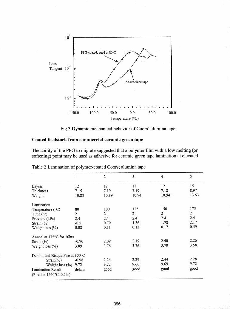
Table 2 Lamination of polymer-coated Coors; alumina tape
Layers 12 Thickness 7.15 Weight 10.83
Lamination Temperature (OC) 80 Time (hr) 2 Pressure (kPa) 2.4 Strain (%) -0.2 Weight loss (%) 0.08
Anneal at 175OC for 1 Ohrs Strain (%) -0.70 Weight loss (%) 3.89
Debind and Bisque Fire at 800°C Strain(%) -0.98 Weight loss (%) 9.72
Lamination Result delam (Fired at 1560°C, 0.5hr)
2.26 9.72 good
2.29 9.66 good
2.44 9.69 good
2.28 9.72 good

temperature. This was the underlying idea for the development at the solid system. The polymer coating on ceramic green tape was made by using a Doctor blade, as would be done in tape casting. Coated feedstocks were laminated using the procedure shown in Fig. 1. Preliminary results have already presented [5]. The detailed results are shown in Table 2. Most laminates are 12 layers. Different lamination temperatures, from 80°C to 175"C, were tested while keeping lamination time and pressure constant. It can be seen that, with increasing lamination temperature, lamination strain increased due to the lowering of viscosity of the polymer film and diffusion into the green tape. After pressureless annealing at 175"C, the strain of all of specimens except for that laminated at 80°C increased to 2.1 to 2.4%, which corresponds to the original polymer film thickness. At this time, it is evident that the polymer coating is diffused into green tape, because the strain after bisque firing at 800°C did not change much. According to the laminate thickness and strain, the polymer coating thickness can be calculated in the range of 14 to 16 pm. It can also be seen that the lamination weight loss is very small if lamination temperature is lower than 175°C. The total weight loss after pressureless annealing is 3.6 to 3.9%. At that time, most plasticizer in the binder, which has much lower molecular weight (300-600) than binder and coating polymer, was evaporated. The total organic component (binder and plasticizer) in ceramic green tape is 8.5wt%. The specimen laminated at 80°C has negative strain due to the buckling delamination. Therefore, lamination temperature should be 100°C or higher. However, the green tape will too soft if temperature is too high.
Fig.4 shows a laminate of coated Coors' alumina tape. The cross-section of fired specimen subjected to a dye-penetrant indicates 100% lamination efficiency. No delamination was observed. Three layer atomizer components also were fabricated using coated Coors' alumina tape, shown in Fig.5. Fugitive tape, made from graphite and corn starch, was used in hollow area to ensure uniform pressure distribution during dead load lamination.
(a)Edge of as-laminated specimen at 125°C for 2 hrs
(b) Cross-section of fired alumina with penetrated ink (anneal at 175°C for 10 hrs, debound at 550°C, and fired at 1 560°C for 30 min
Fig.4 13-layer laminate of coated Coors' alumina (one inch square in green state)
Coated feedstocks of fine ceramic green tapes

Coated feedstock were also prepared from in-house alumina and silicon nitride ceramic green tapes. The two kinds of feedstock were laminated using polymer films of 18 and 28 pm, respectively, at 125°C and then pressureless annealed at 175OC for 15 hrs.
( a ) As-la~i~inated at 125°C
Fired at 1560°C fbr 30 n~ in
Fig.5 3-layer atomizer made from coated Coors' alumina tape
tapc at 1 25°C for 2 hrs
(c) As-laminated coatcd-silicon (d ) Anneal (c) at 175°C for 15 hrs nitride tapc at 1 2S°C for 2 hrs
Fig.6 Cross-section of laminates of coated fine ceramic green tapes

The cross-section of laminates are shown in Fig.6. It can be seen that, unlike Coors' alumina tape, a thin polymer film (3-4 pm) still exists between green tape after 15 hrs annealing at 175OC. The reason is that the polymer coating is too thick. With the diffusion of polymer coating into green tape, the pores at near surface of green tape become saturated and a dense layer was formed at near surface, which is apparent as discoloration. Therefore, continued diffusion of the polymer coating into the green tape will meet high resistance and the diffusion rate will be very slow. It may take longer time (20 or 30 hrs) for polymer coating to diffuse into green tape completely, which is necessary to avoid delamination during firing.
(b) t(pn1 coating ( c ) 3 prn coating
Fig.7 Thinner polymer coating on in-house alumina tape
(a), (b) As-lamirlatcd at 125°C for 2 hrs
(c), (d) Heated to 175OC and hcld for 1 0 hrs
Fig.8 10-layer laminate of coated half-micron alumina tape

Therefore, thinner polymer coatings were prepared by diluting solid concentration in polymer emulsion. Coating thickness can be controlled in the range of 3 to 8 pm, as shown in Fig.7. Coated half-micron alumina tape was laminated at 125OC and then pressurelessly annealed at 175OC. SEM images of cross-section of the laminates are shown in Fig.8. It can be seen that, after annealing at 17 5*C, polymer coating diffused into green tape completely, and the interface between layers disappeared. Alumina atomizers were also fabricated by CAM-LEM machine. All the lamination steps were then finished robotically. Good lamination was obtained.
Conclusions
Liquid-adhesive lamination is a mature technology and has been successfully used to produce advanced ceramic parts. Non-liquid adhesives have been developed and demonstrated. Though solid and nonsticky at room temperature, at low temperatures, it softens and bonds layers together. As temperature is increased, the adhesive becomes fluid and is dissolved in the binder.
(3) Fine particle size green-tape require very controlled thin coating.
References
1. P. Wei, J.D. Cawley, and A.H. Heuer, CAM-LEM Processing of Ceramic Components - Lamination Technology, Proc. 6th Eur. Conf. Rapid Prototyping Manuf., edited by P.M. Dickens, Uni. of Nottingham, 1997,95.
2. J.D. Cawley and Zhien Liu, Applying Tape Casting to Layered Manufacturing Processes, Ceramic Industry, 128[3]42(1998).
3. Zhien Liu, P.Wei, A.H. Heuer; and J.D. Cawley, Metal and Ceramic Components Made via CAM-LEM Technology, Proc. Solid Freeform Fab. Symp., University of Texas at Austin, 1996, pp. 377.
4. Zhien Liu; T-C KO; J. Best; J.D. Cawley, and A.H. Heuer, CAM-LEM Processing: Materials Flexibility, Proc. Solid Freeform Fab. Symp., University of Texas at Austin, 1997, pp. 379.
5. J.D. Cawley; Zhien Liu; J. Mou, and A.H. Heuer, Materials Issues in Laminated Object Manufacturing of Powder-Based Systems, Proc. Solid Freeform Fab. S p p . , University of Texas at Austin, 1998, pp. 503.
6. J.D. Cawley, B.D. Kernan, and W.H. Glime, US Patent Pending. 7. N.Suppakara, PhD Dissertation, Case Western Reserve University, 1999.
Acknowledgements: Brian B. Mathewson at CAM-LEM, Inc. conducted the lamination trials with the CAM-LEM machine and produced the test lot at atomizer. Funding for yhis work was provided through a NASNCWRU Cooperative Agreement on Ceramic Processing (NCC3-404).