ANALYSIS OF CERAMIC (SiC) COATED GAS TURBINE BLADE … · 2017-05-20 · ANALYSIS OF CERAMIC (SiC)...
16
International Journal of Recent Innovation in Engineering and Research Scientific Journal Impact Factor - 3.605 by SJIF e- ISSN: 2456 – 2084 @IJRIER-All rights Reserved -2017 Page 30 ANALYSIS OF CERAMIC (SiC) COATED GAS TURBINE BLADE USING ANSYS Griffin.T 1 and Rajesh Kumar.B 2 1 M.E Engineering Design, Department of Mechanical Engineering, KCG College of Technology, Karapakkam, Chennai, India 2 Assistant Professor, Department of Mechanical Engineering, KCG College of Technology, Karapakkam, Chennai, India Abstract- The ability of gas turbine blades to withstand elongations is a major consideration in their design because they are subjected to high tangential, axial, centrifugal forces during their working conditions. Several methods have been suggested for the better enhancement of the mechanical properties of blades to withstand these extreme conditions. This project summarizes the design and analysis of Gas turbine blade, on which SOLIDWORKS is used for design of solid model of the turbine blade with the help of the spline and extrude options ANSYS software is used analysis of F.E. model generated by meshing of the blade using the solid brick element present in the ANSYS software itself and thereby applying the boundary condition. This project specifies how the program makes effective use of the ANSYS pre-processor to analyse the complex turbine blade geometries and apply boundary conditions to examine steady state thermal & structural performance of the blade which is coated with SiC/SiC (Ceramic Matrix composites), and uncoated Titanium Alloy Ti 6Al 4V, Inconel 718 Alloy, Multimet N155, Incoloy A286, Haynes 188. Finally stating the best suited material among them from the report generated after analysis & to perform flow analysis using CFD. From this the results are stated and reported. Keywords- Thermal & Structural Analysis, Von-Misses stress, deformation, Flow Analysis. I. INTRODUCTION The gas turbine obtains its power by utilizing the energy of burnt gases and the air which is at high temperature and pressure by expanding through the several rings of fixed and moving blades, to get a high pressure of order of 4 to 10 bar of working fluid which is essential for expansion a compressor is required. The quantity of working fluid and speed required are more, so generally a centrifugal or axial compressor is required. The turbine drive the compressor so it is coupled to the turbine shaft, If after compression the working fluid were to be expanded in a turbine, then assuming that there were no losses in either component, the power developed by the turbine can be increased by increasing the volume of working fluid at constant pressure or alternatively increasing the pressure at constant volume. Either of there may be done by adding heat so that the temperature of the working fluid is increased after compression. To get a higher temperature of the working fluid a combustion chamber is required where combustion of air and fuel takes place giving temperature rise to the working fluid. The turbine escapes energy from the exhaust gas. Like the compressor, turbine can be centrifugal or axial. In each type the fast moving exhaust gas is sued to spin the turbine, since the turbine is attached to the same shaft as the compressor at the front of the engine, and the compressor will turn together, the turbine may extract just enough energy to turn the compressor. The rest of the exhaust gas is left to exit the rear of the engine to provide thrust as in a pure jet engine. Or extra turbine stages may be used to turn other shafts to power other machinery such as the rotor of a helicopter, the propellers of a ship or electrical generators in power stations. II. LITERATURE REVIEW Literature Review works as a study which gives a guideline to perform 3D Modelling & analysis for the component. The facts and data which is required to solve the problem can be learned
Transcript of ANALYSIS OF CERAMIC (SiC) COATED GAS TURBINE BLADE … · 2017-05-20 · ANALYSIS OF CERAMIC (SiC)...
International Journal of Recent Innovation in Engineering and Research Scientific Journal Impact Factor - 3.605 by SJIF
e- ISSN: 2456 – 2084
@IJRIER-All rights Reserved -2017 Page 30
ANALYSIS OF CERAMIC (SiC) COATED GAS TURBINE BLADE
USING ANSYS
Griffin.T1 and Rajesh Kumar.B
2
1M.E Engineering Design, Department of Mechanical Engineering, KCG College of Technology,
Karapakkam, Chennai, India 2Assistant Professor, Department of Mechanical Engineering, KCG College of Technology, Karapakkam,
Chennai, India
Abstract- The ability of gas turbine blades to withstand elongations is a major consideration
in their design because they are subjected to high tangential, axial, centrifugal forces during
their working conditions. Several methods have been suggested for the better enhancement of
the mechanical properties of blades to withstand these extreme conditions. This project
summarizes the design and analysis of Gas turbine blade, on which SOLIDWORKS is used
for design of solid model of the turbine blade with the help of the spline and extrude
options ANSYS software is used analysis of F.E. model generated by meshing of the blade
using the solid brick element present in the ANSYS software itself and thereby applying the
boundary condition. This project specifies how the program makes effective use of the
ANSYS pre-processor to analyse the complex turbine blade geometries and apply boundary
conditions to examine steady state thermal & structural performance of the blade which is
coated with SiC/SiC (Ceramic Matrix composites), and uncoated Titanium Alloy Ti 6Al 4V,
Inconel 718 Alloy, Multimet N155, Incoloy A286, Haynes 188. Finally stating the best suited
material among them from the report generated after analysis & to perform flow analysis using
CFD. From this the results are stated and reported.
Keywords- Thermal & Structural Analysis, Von-Misses stress, deformation, Flow Analysis.
I. INTRODUCTION
The gas turbine obtains its power by utilizing the energy of burnt gases and the air which is at
high temperature and pressure by expanding through the several rings of fixed and moving blades, to
get a high pressure of order of 4 to 10 bar of working fluid which is essential for expansion a
compressor is required. The quantity of working fluid and speed required are more, so generally a
centrifugal or axial compressor is required. The turbine drive the compressor so it is coupled to the
turbine shaft, If after compression the working fluid were to be expanded in a turbine, then assuming
that there were no losses in either component, the power developed by the turbine can be increased by
increasing the volume of working fluid at constant pressure or alternatively increasing the pressure at
constant volume. Either of there may be done by adding heat so that the temperature of the working
fluid is increased after compression.
To get a higher temperature of the working fluid a combustion chamber is required where
combustion of air and fuel takes place giving temperature rise to the working fluid. The turbine
escapes energy from the exhaust gas. Like the compressor, turbine can be centrifugal or axial. In each
type the fast moving exhaust gas is sued to spin the turbine, since the turbine is attached to the same
shaft as the compressor at the front of the engine, and the compressor will turn together, the turbine
may extract just enough energy to turn the compressor.
The rest of the exhaust gas is left to exit the rear of the engine to provide thrust as in a pure jet
engine. Or extra turbine stages may be used to turn other shafts to power other machinery such as the
rotor of a helicopter, the propellers of a ship or electrical generators in power stations.
II. LITERATURE REVIEW
Literature Review works as a study which gives a guideline to perform 3D Modelling &
analysis for the component. The facts and data which is required to solve the problem can be learned
Volume: 02 Issue: 05 May– 2017 (IJRIER)
Available Online at : www.ijrier.com Page 31
from it. Literature Review provides these information and suggestions in the form of journals and
other sources.
Various bodies of research have been performed in the past to address the problem of
unsteady heat transfer on turbine blades. These attempts include experimental, as well as
computational examinations of unsteady heat transfer (through shock waves) on the surface of a
turbine blade. While the problem of predicting shock-induced heat transfer continues to be difficult
on all levels, the benefit of doing so remains worthwhile. Useful analytical and numerical
simulations can potentially aid the turbine designer towards accurate predictions of blade heat
transfer.
III. METHODOLOGY
Problem definition.
Calculate the dimensions of blade profile
Generate the 3-dimentional computer models
Prepare finite element model of the 3D computer model
Pre-process the 3D model for the defined geometry
Mesh the geometry model and refine the mesh considering sensitive zones for results accuracy
Post process the model for the required evaluation to be carried out
Determine the temperature distribution along the blade profile.
Determine maximum stress induced in blades.
Perform Flow Analysis using CFD
Conclude the results.
IV. DEFINITION OF PROBLEM
The Aim of the project is to prefer the best suitable blade material for the gas turbine since
the existing alloys generates more heat during operation which leads to oxidation, hot corrosion,
Interdiffusion, Thermal Fatigue, in order to overcome these causes ceramic matrix composites
(Silicon Carbide) can be used as coating medium to rectify the problems. Comparison has been made
by using coating materials in design software to get a better replacement in future. In achieving this
aim, project objectives are set as below:
To understand the working principles, components, standards and theories through a literature
study.
To understand the working principle of FEA Software (ANSYS)
To understand the fundamental of heat transfer through thermal analysis of turbine blade.
To clearly justify the result and conclusion.
The knowledge gained from this project is to be able to understand the steps needed in
thermal analysis & structural analysis of turbine blade by using FEA method. The methods used in
this project can later be used in future as reference for similar research and development. There is the
wide range of study on the turbine blade. The turbine blade could be studied on the various areas
such as material improvement on the turbine blade, vibration on the turbine blade, air flow analysis
of the turbine blade and thermal stress analysis on the turbine blade.
V. TURBINE BLADE
A turbine blade is the individual component which makes up the turbine section of a gas
turbine. The blades are responsible for extracting energy from the high temperature, high pressure gas
produced by the combustor. To survive in this difficult environment, turbine blades often use exotic
materials like super alloys and many different methods of cooling, such as internal air
channels, boundary layer cooling, and thermal barrier coatings. Blade fatigue is a major source of
failure in steam turbines and gas turbines.

Volume: 02 Issue: 05 May– 2017 (IJRIER)
Available Online at : www.ijrier.com Page 32
Fatigue is caused by the stress induced by vibration, temperature, resonance within the
operating range of machinery.
VI. CREAMIC COATING
Silicon carbide is an excellent abrasive and has been produced and made into grinding wheels and
other abrasive products for over one hundred years.
The material has been developed into a high quality technical grade ceramic with very good
mechanical properties.
It is used in abrasives, refractories, ceramics, and numerous high-performance applications.
Structural and wear applications are constantly developing.
VII. MODELLING APPROACHES
Solidworks is used as the modelling tool in this project. The real time design of Gas Turbine
Blade is taken as the model. Modelling is made with the exact dimensions.It integrates easy-to-use
analysis tools with design to verify operation and performance during product development.
SolidWorks design analysis increases product innovation by reducing risk in design,
significantly reduces the number of physical prototypes needed, and helps lower material and other
costs.
TABLE I. MATERIAL PROPERTIES

Volume: 02 Issue: 05 May– 2017 (IJRIER)
Available Online at : www.ijrier.com Page 33
A) SPECIFICATION OF UNCOATED BLADE
B) SPECIFICATION OF COATED BLADE
Height of the blade = 120mm
Length of the blade (L) = 49.20 mm
Width of the blade (B) = 27.58 mm
Chord Width (c) = 9.5mm
Blade inlet angle (β1) = 136.4
0
Blade outlet angle (β2) = 68.2
0
Absolute flow angle (α) = 24.150
Speed of Turbine (N) = 3426 rpm
Diameter of blade mid span (D) = 1308.5 m
Diameter of convection holes, d1
= 2.5mm
d2= 2mm
d3=1.25mm
Height of the blade = 120mm
Length of the blade (L) = 49.90 mm
Width of the blade (B) = 28.28 mm
Chord Width (c) = 10.23mm
Blade inlet angle (β1) = 136.4
0
Blade outlet angle (β2) = 68.2
0
Absolute flow angle (α) = 24.150
Speed of Turbine (N) = 3426 rpm
Thickness of Ceramic Coating (t) = 0.35mm
Diameter of blade mid span (D) = 1308.5 mm
Diameter of convection holes, d1
= 1.8mm
d2=1.3mm
d3=0.55mm

Volume: 02 Issue: 05 May– 2017 (IJRIER)
Available Online at : www.ijrier.com Page 34
VIII. RESULT & DISCUSSIONS
A) THERMAL ANALYSIS
Boundary conditions provided for Temperature Distribution are Heat Flux & Convection. For
this analysis, Thermal Conductivity was the required mechanical properties for these alloys. The
temperature distribution of the blade depends on the heat transfer coefficient for gases and the
thermal conductivity of the material. The heat transfer coefficients are calculated by iterative process
and the same were adopted. The analysis was carried out for steady state heat transfer conditions.
The difference between uncoated & coated alloy in temperature distribution is observed from results
below.
TITANIUM ALLOY (Ti 6Al 4V)
Fig:-8.1 Temperature Distribution (Uncoated)
Fig:- 8.2 Temperature Distribution (Coated)
INCONEL 718
Fig:-8.3 Temperature Distribution (Uncoated)

Volume: 02 Issue: 05 May– 2017 (IJRIER)
Available Online at : www.ijrier.com Page 35
Fig:-8.4 Temperature Distribution (Coated)
MULTIMET N155
Fig:-8.5 Temperature Distribution (Uncoated)
MULTIMET N155
Fig:-8.6 Temperature Distribution (Coated)
INCOLOY A286
Fig:-8.7 Temperature Distribution (Uncoated)

Volume: 02 Issue: 05 May– 2017 (IJRIER)
Available Online at : www.ijrier.com Page 36
Fig:-8.8 Temperature Distribution (Coated)
HAYNES 188
Fig:-8.9 Temperature Distribution (Uncoated)
Fig:-8.10 Temperature Distribution (Coated)
It is observed that the maximum temperatures are prevailing at the leading edge of the blade
due to the stagnation effects. The body temperature of the blade doesn’t vary much in the radial
direction. However, there is a temperature fall from the leading edge to the trailing edge of the blade
as expected. From the above result, the alloy with coated exhibits
Better dissipation of heat compared to uncoated alloys. The coated Haynes 188 alloy
generates less heat compared to other alloys so it’s recommended for Higher Thermal operating
conditions.

Volume: 02 Issue: 05 May– 2017 (IJRIER)
Available Online at : www.ijrier.com Page 37
B) STRUCTURAL ANALYSIS
Structural Analysis is performed to determine the Total Deformation & Equivalent Stress
(Von-Mises) among the various alloys with & without the ceramic coating. Boundary conditions
required for the analysis are Centrifugal force, Tangential force, axial force & the temperature
obtained from thermal analysis is also imported.
TITANIUM ALLOY (Ti 6Al 4V)
Fig: - 8.11 Total Deformation (Uncoated)
Fig: - 8.12 Total Deformation (Coated)
Fig:- 8.13 Von-Mises Stress (Uncoated)
Fig:- 8.13 Von-Mises Stress (Coated)

Volume: 02 Issue: 05 May– 2017 (IJRIER)
Available Online at : www.ijrier.com Page 38
INCONEL 718
Fig: - 8.14 Total Deformation (Uncoated)
Fig: - 8.15 Total Deformation (Coated)
INCONEL 718
Fig:- 8.16 Von-Mises Stress (Uncoated)
Fig:- 8.17 Von-Mises Stress (Coated)

Volume: 02 Issue: 05 May– 2017 (IJRIER)
Available Online at : www.ijrier.com Page 39
MULTIMET N155
Fig: - 8.18 Total Deformation (Uncoated)
Fig: - 8.19 Total Deformation (Coated)
Fig: - 8.20 Von-Mises Stress (Uncoated)
Fig:- 8.21 Von-Mises Stress (Coated)
Volume: 02 Issue: 05 May– 2017 (IJRIER)
Available Online at : www.ijrier.com Page 40
INCOLOY A286
Fig: - 8.22 Total Deformation (Uncoated)
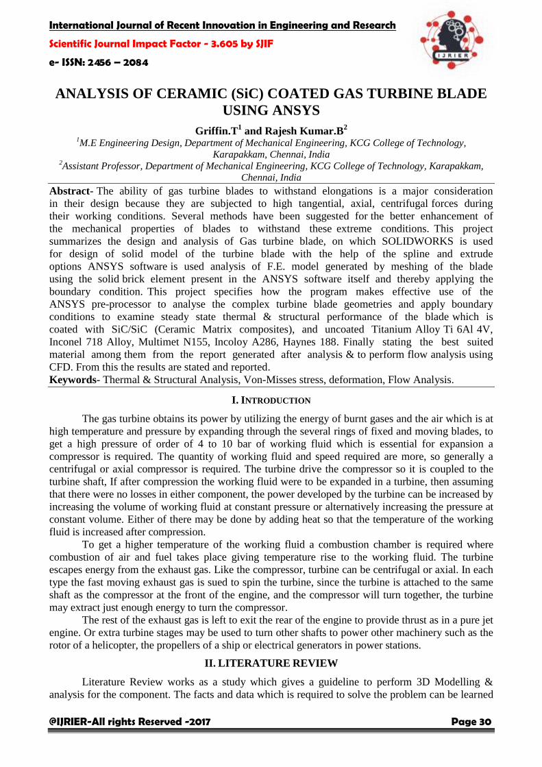
Fig: - 8.23 Total Deformation (Coated)
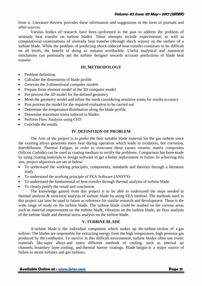
Fig: - 8.24 Von-Mises Stress (Uncoated)
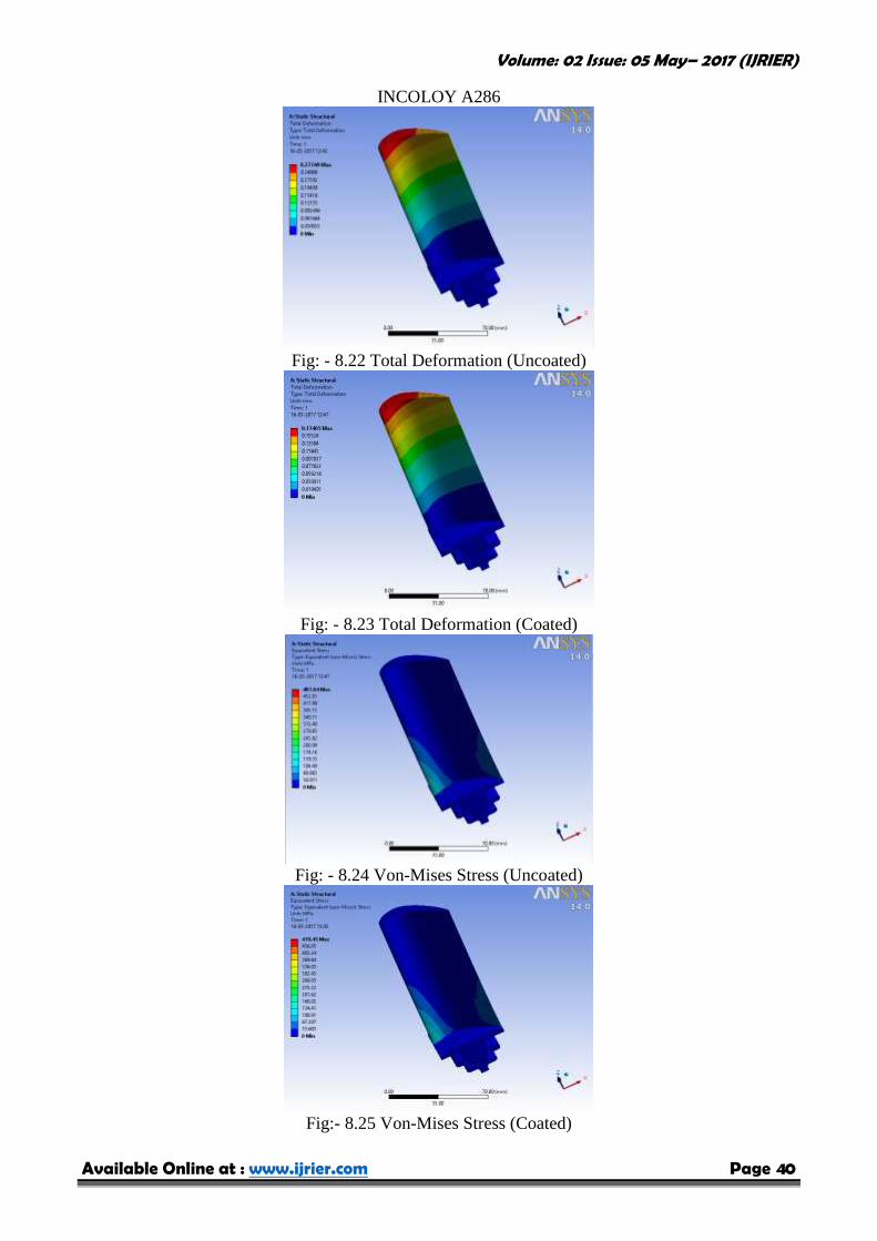
Fig:- 8.25 Von-Mises Stress (Coated)

Volume: 02 Issue: 05 May– 2017 (IJRIER)
Available Online at : www.ijrier.com Page 41
HAYNES 188
Fig: - 8.26 Total Deformation (Uncoated)
Fig: - 8.27 Total Deformation (Coated)
Fig: - 8.28 Von-Mises Stress (Uncoated)
Fig:- 8.29 Von-Mises Stress (Coated)

Volume: 02 Issue: 05 May– 2017 (IJRIER)
Available Online at : www.ijrier.com Page 42
As the blades are not shrouded so the stress on the tip of the blade are lesser and higher
values of stress is coming on the root of the blades. It is evident that the deformation is distributed in
an ascending manner from the bottom of the hub to the tip of the blade. From the results from
structural analysis, it is clear that the Deformation & Von- Mises Stress is less in coated Haynes 188
Alloy compared to other alloys.so Coated Haynes 188 can be used in all sorts of Thermal &
Structural Conditions.
C) FLOW ANALYSIS
Fig:- 8.30 Contour Plot of Flow Velocity
Fig:- 8.31 Contour Plot of Flow Pressure
Fig:- 8.32 Flow of Streamline Velocity

Volume: 02 Issue: 05 May– 2017 (IJRIER)
Available Online at : www.ijrier.com Page 43
Fig:- 8.33 Flow of Streamline Pressure Gradient
Fig:- 8.34 Flow of Streamline Velocity
The Flow Analysis is performed using Fluid Flow (FLUENT), which was used to
demonstrate & understand the flow over turbine blade through velocity & pressure. The Boundary
condition applied are inlet velocity, Exit pressure, outlet pressure, Temperature, Inlet turbulence
intensity.
TABLE II: Temperature Distribution
Variables Unit Titanium
Alloy
Inconel
718
Multimet
N155
Incoloy
A286
Haynes
188
Uncoated
0C
1068
1002.6
956.5
946.11
945.42
Coated
1036.5
981.71
943.45
934.92
934.35
TABLE III: Total Deformation
Variables Unit Titanium
Alloy
Inconel
718
Multimet
N155
Incoloy
A286
Haynes
188
Uncoated
mm
0.46388
0.27912
0.39011
0.27749
0.23981
Coated
0.19977
0.17498
0.19204
0.17465
0.16645

Volume: 02 Issue: 05 May– 2017 (IJRIER)
Available Online at : www.ijrier.com Page 44
TABLE IV: Von-Mises Stress
Variables Unit Titanium
Alloy
Inconel
718
Multimet
N155
Incoloy
A286
Haynes
188
Uncoated
MPa
484.17
489.31
487.98
487.64
483.27
Coated
461.36
474.64
471.3
470.45
458.93
TABLE V: Flow Analysis
Variable 0 degree of AOA
Drag Force 313.619 N
Lift Force 74.48 N
Drag Coefficient 0.0093021
Lift Coefficient 0.0022088
IX. CONCLUSION
It is seen from above results all the materials are giving the considerable results; finally the
conclusion can be done on the basis of the best suitable material.
The temperature has a significant effect on the von Mises stress in the turbine blade.
Maximum elongation and temperatures are observed at the blade tip section and minimum
elongation and temperature variations at the root of the blade.
The thermal stresses are predominant in the analysis when compared to the Pressure and
Centrifugal forces.
Deformations gradually increase along the blade length from root to the tip portion of the
blade.
For the selection of the best material, Coated Haynes 188 Alloy performance better than other
alloys in all aspects such as Temperature Distribution, Total Deformation & Von-Mises
Stress.
The Flow Analysis is made possible to study the flow through velocity & pressure on the
Turbine Blade.
REFERENCES
[1] Abdulla R. Al Ali, Isam Janajreh (2015), ‘Numerical Simulation of Turbine Blade Cooling via Jet Impingement’,
Energy Procedia, Volume 75, Pages 3220-3229.
[2] Ahmed Abdulhussein Jabbar, Rai A.K.,Ravinder Reedy P., Mahmood Hasan Dakhil (2014), ‘Design and Analysis of
Gas Turbine Rotor Blade using Finite Element Method’ Engineering Research and Development, Vol. 4, Issue 1,73-
94.
[3] Alaa A. El-Shazly, Mohamed Elhelw, Medhat M. Sorour, Wael M. El-Maghlany (2016), ‘Gas turbine performance
enhancement via utilizing different integrated turbine inlet cooling techniques’, Alexandria Engineering Journal,
Volume 55, Issue 3, Pages 1903-1914.
[4] Ameni A. A., Steinthorsson E. (1996), ‘Analysis of Gas Turbine Rotor Blade Tip and Shroud Heat Transfer’, The
American Society of Mechanical Engineers Journal, Volume-3, Issue-2, Pages 71-79.
[5] Attarian M., Khoshmanesh R., Nategh S., Davami P. (2013), ‘Microstructural evaluation and fracture mechanisms of
failed IN-738LC gas turbine blades’, Case Studies in Engineering Failure Analysis, Volume 1,Issue 2, Pages 85-94.
[6] Boris Rottwinkel, Christian Nölke, Stefan Kaierle, Volker Wesling (2014), ‘Crack Repair of Single Crystal Turbine
Blades Using Laser Cladding Technology’, Procedia CIRP, Volume 22, Pages 263-267.
[7] Brandão P., Infante V., Deus A.M. (2016), ‘Thermo-mechanical modelling of a high pressure turbine blade of an
airplane gas turbine engine’, Procedia Structural Integrity, Volume 1, Pages 189-196.
[8] Carlos A. Estrada M. (2007), ‘New Technology used in Gas Turbine Blade Materials’, Technological University of
Pereira, Volume-5, Issue-3, Pages 112-120.

Volume: 02 Issue: 05 May– 2017 (IJRIER)
Available Online at : www.ijrier.com Page 45
[9] Chengwei Fei, Guangchen Bai (2012), ‘Extremum selection method of random variable for nonlinear dynamic
reliability analysis of turbine blade deformation’, Propulsion and Power Research, Volume 1, Issue 1, Pages 58-63.
[10] Gopinath Chintala, Prasad Gudimetla (2014), ‘Optimum Material Evaluation for Gas Turbine Blade Using Reverse
Engineering (RE) and FEA’, Procedia Engineering, Volume 97, Pages 1332-1340.
[11] Hwan Shin , Dong Keun Lee , Yong Seok Kim , Jae Mean Koo , Chang Sung Seok, Tack Woon Lee (2013),
‘Assessment of the Characteristic of Thermal Barrier Coating Applied to Gas Turbine Blade by Thermo-Gradient
Mechanical Fatigue Test’, Procedia Engineering, Volume 55, Pages 210-213.
[12] Jae Hoon Kim, Ho Young Yang , Keun Bong Yoo (2011), ‘A study on life prediction of low cycle fatigue in super
alloy for gas turbine blades’, Procedia Engineering, Volume 10, Pages 1997-2002.
[13] Jens Aschenbruck, Rafael Adamczuk, Joerg R. Seume (2014), ‘Recent Progress in Turbine Blade and Compressor
Blisk Regeneration’, Procedia CIRP, Volume 22, Pages 256-262.
[14] Krishnakanth P.V., Narasa Raju G., Prasad R. D. V., Saisrinu R. (2013), ‘Analysis of Gas Turbine Blade by Using
F.E.M’, International Journal of Scientific Research Engineering & Technology, Volume-2, Issue-2, Pages 60-65.
[15] Li Xu, Sun Bo, You Hongde, Wang Lei (2014), ‘Evolution of Rolls-Royce air-cooled turbine blades and feature
analysis’, Procedia Engineering, Volume 99, Pages 1482-1491.

![Chapter 2 SiC Materials and Processing Technology€¦ · 34 2 SiC Materials and Processing Technology Table 2.1 Key electrical parameters of SiC [1] Property 4H-SiC 6H-SiC 3C-SiC](https://static.fdocuments.in/doc/165x107/5f4fd11797ddad63bf719816/chapter-2-sic-materials-and-processing-technology-34-2-sic-materials-and-processing.jpg)