Coagulation and Flocculation Part-I · • In the flash mixer, coagulant chemicals are added to the...
78
L-17 Coagulation and Flocculation Part-I Environmental Engineering-I
Transcript of Coagulation and Flocculation Part-I · • In the flash mixer, coagulant chemicals are added to the...

L-17
Coagulation and Flocculation
Part-I
Environmental Engineering-I

Content Part-I
• Coagulation, Types of Coagulant,
Part-II
• dosing, rapid mixing, Flocculation-design
parameters.

Purpose
• The primary purpose of the
coagulation/flocculation process is the
removal of turbidity from the water.
• Turbidity is a cloudy appearance of
water caused by small particles
suspended therein.
• Water with little or no turbidity will be
clear.
• Water with a high turbidity can be very
difficult to properly disinfect.
•


Why coagulation and flocculation?
Various sizes of particles in raw water Particle diameter (mm) Type Settling velocity
10 Pebble 0.73 m/s
1 Course sand 0.23 m/s
0.1 Fine sand 0.6 m/min
0.01 Silt 8.6 m/d
0.0001 (10 micron) Large colloids 0.3 m/y
0.000001 (1 nano) Small colloids 3 m/million y
Colloids – so small in size: gravity settling not
possible
G r
a v
I t y
s e
t t l I n
g

Coagulant aided sedimentation required to
remove following impurities
1. Miscellaneous fragments of animal and
vegetable matter
2. plankton mainly phytoplankton (microscopic
plants).
3. Finely divided colloidal matter and clay.
4. Organic colouring matter partly in solution and
partly in colloidal form.
5. Bacteria and viruses in small extent
6. Complex mixture of organic compounds

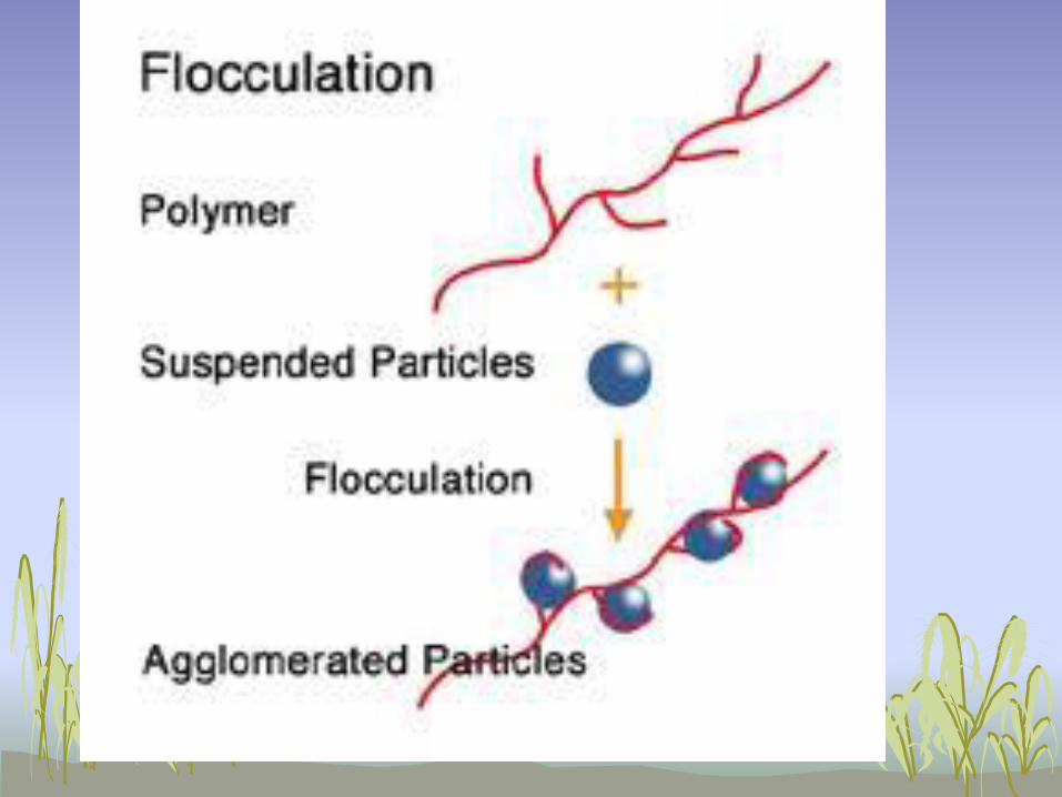
Coagulation-Flocculation
• In conventional coagulation-flocculation-
sedimentation, a coagulant is added to
the source water to create an attraction
among the suspended particles.
• The mixture is slowly stirred to induce
particles to clump together into “flocs.”
• The water is then moved into a quiet
sedimentation basin to settle out the
solids.

• In the flash mixer, coagulant chemicals are
added to the water and the water is mixed
quickly and violently.
• The purpose of flash mixing is to evenly
distribute the chemicals through the water.
• Flash mixing typically lasts a minute or
less. If the water is mixed for less than thirty
seconds, then the chemicals will not be properly
mixed into the water.
• However, if the water is mixed for more than
sixty seconds, then the mixer blades will shear
the newly forming floc back into small particles.

• After flash mixing, coagulation occurs. During
coagulation, the coagulant chemicals
neutralize the electrical charges of the fine
particles in the water, allowing the particles to
come closer together and form large clumps.
• The final step is flocculation. During
flocculation, a process of gentle mixing
brings the fine particles formed by
coagulation into contact with each other.
• Flocculation typically lasts for about thirty
to forty-five minutes.
•

To summarize,
• Coagulation Is
• The addition and rapid mixing of
coagulants
• The destabilization of colloidal and fine
particles
• The initial aggregation of destabilized
particles
• Flocculation Is
• The gentle agitation to aggregate
destabilized particles to form rapid-settling
floc


THEORY OF COAGULATION
L-18


Destabilization of colloidal particles
takes place by following ways Coagulation and flocculation can be
caused by any of the following:
1. Double layer compression
2. Charge neutralization
3. Bridging
4. Colloid entrapment

1. DOUBLE LAYER
COMPRESSION THEORY


•Surface charge - charged ions (commonly
negative) adsorbed on the particle surface.
•Stern layer - counter ions (charged opposite to
the surface charge) attracted to the particle
surface and closely attached to it by the
electrostatic force.
•Diffuse layer - a film of the dispersion medium
(solvent) adjacent to the particle. Diffuse layer
contains free ions with a higher concentration of
the counter ions. The ions of the diffuse layer are
affected by the electrostatic force of the charged
particle.
An Electric Double Layer consists of three
parts:

•The amount of coagulant which should be
added to the water will depend on the zeta
potential, a measurement of the
magnitude of electrical charge
surrounding the colloidal particles.
•The zeta potential as the amount of
repulsive force which keeps the particles
in the suspension.
• If the zeta potential is large, then more
coagulants will be needed.

• When coagulants(Electrolytes) are
added into the water it changes ionic
concentration.
• Which compresses double layer and
weakens repulsive forces.
• The basic goal of coagulation is to
reduce the net repulsive force.

Double layer
gets
compressed
after addition of
coagulant

2. Charge Neutralization

3. Bridging

• Bridging occurs when a coagulant
forms threads or fibers which attach
to several colloids, capturing and
binding them together.
• Inorganic primary coagulants and
organic polyelectrolytes both have
then capability of bridging.
• Higher molecular weights mean
longer molecules and more
effective bridging.

4. Colloidal entrapment


Factors affecting coagulation
1. Types of coagulant
2. Quantity or dose of coagulant
3. Characteristics of water such as
- Type and quantity of suspended matter
- Temperature of water
- pH of water
4. time, turbulence and method of mixing
L-19
Jar Test and
Common coagulants

JAR TEST
A jar test simulates the coagulation and
flocculation processes in batch mode

30
Fill the jars with raw water sample (500 or
1000 mL) – usually 6 jars
This time adjust pH of all jars at optimum (@ 7)
while mixing using H2SO4 or NaOH/lime
Add different doses of the selected coagulant (alum
or iron) to each jar (Coagulant dose: 0 to 50 mg/Lit-
interval of 10 mg/Lit)
Rapid mix each jar at 100 to 150 rpm for 1 minute.
The rapid mix helps to disperse the coagulant
throughout each container
Reduce the stirring speed to 25 to 30 rpm for 25 to
30 mins
STEPS


• Turn off the mixers and allow flocs to settle for 30 to
45 mins
• Then measure the final residual turbidity in each jar
• Plot residual turbidity against coagulant dose
The coagulant dose with the lowest residual
turbidity will be the optimum coagulant dose

Coagulants
• Mainly aluminum and iron salts
1. Aluminum sulfate
2. Chlorinated copperas
3. Ferrous sulfate and lime
4. Magnesium carbonate and lime
5. Sodium Aluminate
• Aluminum salts are cheaper but iron
salts are more effective over wider pH
range

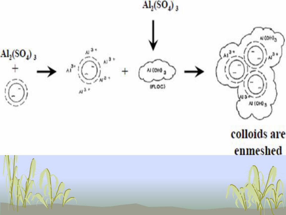
1. Aluminum Sulfate or Alum
• To produce the hydroxide floc, enough
alkalinity should present in the water
• If alkalinity is not enough, then it should
be added. Usually hydrated lime is used
for that purpose (optimum pH is 6.5 –
8.5)


• Under normal circumstances Dose of Alum
varies from 10 to 30 mg/lit of water.
Advantages
1. Alum reduces taste and odour
2. Cheap
3. Easily available
4. Soluble in water
Disadvantages
1. Difficult to dewater the sludge

2. Ferrous Sulfate (Chlorinated
Copperas)
• The optimum pH range is 3.5 to 6.5
• At higher pH i.e. 9.5 it removes
manganese
• More expensive than alum
• Effective in colour removal.
• Low solubility in water

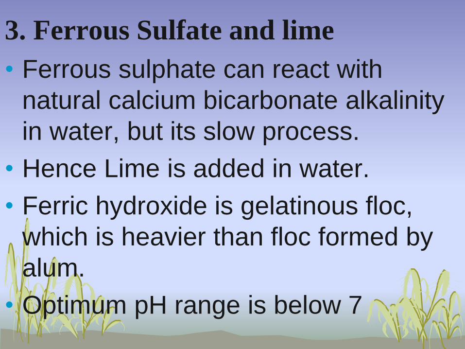
3. Ferrous Sulfate and lime
• Ferrous sulphate can react with
natural calcium bicarbonate alkalinity
in water, but its slow process.
• Hence Lime is added in water.
• Ferric hydroxide is gelatinous floc,
which is heavier than floc formed by
alum.
• Optimum pH range is below 7


4. Magnesium carbonate and
lime
Byproducts of above reaction forms
soluble sludge, so not commonly used

5. Sodium Aluminate

Comparison of Alum and Iron salt
1. Iron salts forms heavy floc as compared
to alum, hence more Solids are removed
2. time of reaction and floc formation is less
for iron salts, hence ‘t’ reduces.
3. Iron salts can work efficiently over wider
pH range
4. Iron salts can remove taste and odour.
5. Less mud ball formation as compared to
alum

6. Under some cases iron salts are more
economical.
7. Iron salts cause staining and promotes
growth of iron bacteria.
8. Iron salts make water more corrosive as
compared to alum
9. Handling of iron salts requires skill.
10. More CO2 is formed so water becomes
corrosive.
11. Alum Coagulation may not be proper if K
or Na are present in water

L-20

Coagulant Aids
• Are used to produce quick-
forming, dense and rapid-settling
flocs
• Polyelectrolytes
• pH adjustment
• Alkalinity addition
• Turbidity addition

Polyelectrolytes
• Anionic (-vely charged)
• Cationic (+vely charged)
• Polyampholites (both +vely and –vely charged groups)
• Natural such as starch
• Synthetic (more common in coagulation)
• They aid in coagulation by: • Chemical bridging
• Interaction between reactive groups on the polyelectrolyte and the floc

pH Adjustment
• Is used if pH of water to be treated is
not within the optimum pH of the
coagulant
• pH is increased using lime
• pH is reduced using sulfuric acid

Alkalinity Addition
• Is used when natural alkalinity is not
enough to produce good floc
• Hydrated or slaked lime is used
• Soda ash (Na2CO3) is also used
(expensive)

Turbidity Addition
• Is used to provide sufficient
particulate concentration to achieve
rapid coagulation through sufficient
inter-particle collision
• Is done by recycling chemically
precipitated sludge
• Bentonite Clays are also used for that
purpose
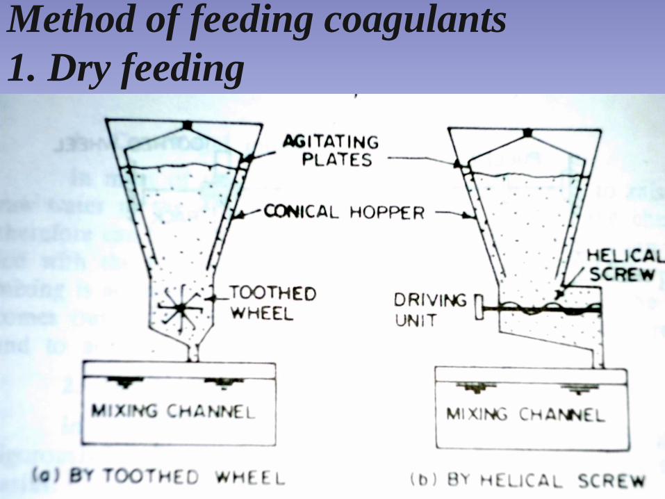
Method of feeding coagulants
1. Dry feeding

2. Wet feeding


Mixing devices: Hydraulic
mixing in water flow
a. Channel
with baffles
b. Overflow
weir
c. Hydraulic
jump mixing


Mixing devices : Hydraulic mixing in
flocculation tank
• A. Vertical
flow
• B. Horizontal
flow
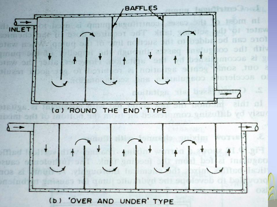

• Horizontally baffled tank
• Vertically baffled tank
The water flows horizontally.
The baffle walls help to create turbulence and thus
facilitate mixing
The water flows vertically.
The baffle walls help to create turbulence and
thus facilitate mixing


Flash mixer

L-20
DESIGN OF FLOCCULATOR

Vertical shaft flocculator
BLADES


Horizontal shaft flocculator

Plank
Shaft


Paddle
blades
Shaft

Paddle blade flocculator
• The Main design parameters of
flocculator units are:
• mixing time, t
• volume of flocculator V,
• velocity gradient, G

10 to 75 1/s
Low

Design criteria for flocculator
1. Depth of tank = 3 to 4.5 m (some times 5)
2. Detention time 10 to 40 min (30 min)
3. Velocity of flow = 0.2 to 0.8 m/s (0.4 m/s)
4. Total area of paddles = 10 to 25 % of c/s area
5. Peripheral velocity of blades = (Should be less
than 1 m/s ) 0.2 to 0.6 m/s
6. Velocity gradient G = 10 to 75 s-1
7. G.t factor = 104 to 105
8. Power consumption = 10 to 36 KW/mld

9. Outlet flow velocity = 0.15 to 0.25 m/s
10. CD = 1.8 for flat blades
11. Distance between paddle edge and side of
basin = 15 to 40 cm
12. K=0.25
13. Relative velocity is 75% of paddle velocity
i.e. vr = 0.75% x vp
14. Area of paddles = length of blades x width x
no. of blades in that compartment
i.e. Ap = lb x w x n
15. Distance between two paddles in same
compartment (in plan)= about 1m

Objective Questions
1. For design of flocculator G value shall be in
the range of ___ to ___ 1/s.
2. Relative velocity shall be assumed as __%
of paddle velocity.
3. __________ is commonly used as
coagulant.
4. Optimum pH range for alum is ___ to ___.
5. _____ mixing is done in flash mixer,
whereas ______ mixing is done in
flocculator.

Theory Questions 1. Explain theory of coagulation.
2. Write detailed note on ‘design of flocculator’.
3. List out coagulants used in water treatment
and explain any one with the help of chemical
reactions.
4. What are coagulant aids?
5. Compare Alum and iron salts as coagulants.