CO2 Sequestration Breakthrough Program Phase I:...
30
CO 2 Sequestration Breakthrough Program Phase I: Geological Sequestration of CO 2 by Hydrous Carbonate Formation with Reclaimed Slag (Accelerated Slag Aging Using Steelmaking Off-Gas) Von L. Richards, Kent Peaslee, and Jeff Smith Goal: Evaluate the technical and economic feasibility of using steelmaking off-gas to rapidly carbonize (age) steelmaking slag for beneficial re-use.
Transcript of CO2 Sequestration Breakthrough Program Phase I:...

CO2 Sequestration Breakthrough Program Phase I:
Geological Sequestration of CO2by Hydrous Carbonate Formation
with Reclaimed Slag(Accelerated Slag Aging Using Steelmaking Off-Gas)
Von L. Richards, Kent Peaslee, and Jeff Smith
Goal: Evaluate the technical and economic feasibility of using steelmaking off-gas to rapidly carbonize (age) steelmaking slag for beneficial re-use.

Slag CO2 Capture PotentialSlag produced per ton steel (NSA)
BOF: 75-150 kg, EAF: 65-80 kg, LMF: 15-20 kg30-50 wt.% CaO / 10-12 wt.% MgO
Kgs of CO2 sequestered per ton slag1000 kgs slag could capture 398.8 kgs CO2398.8 kgs CO2 = 108.9 kgs CO2 (CE)
CO2 per ton liquid steel at furnacesBOF: 187 kg CE EAF: 24 kg CE
Theoretical maximum percentage of offgas CO2 sequestered by slag
BOF: 6-11% EAF: 35-45%
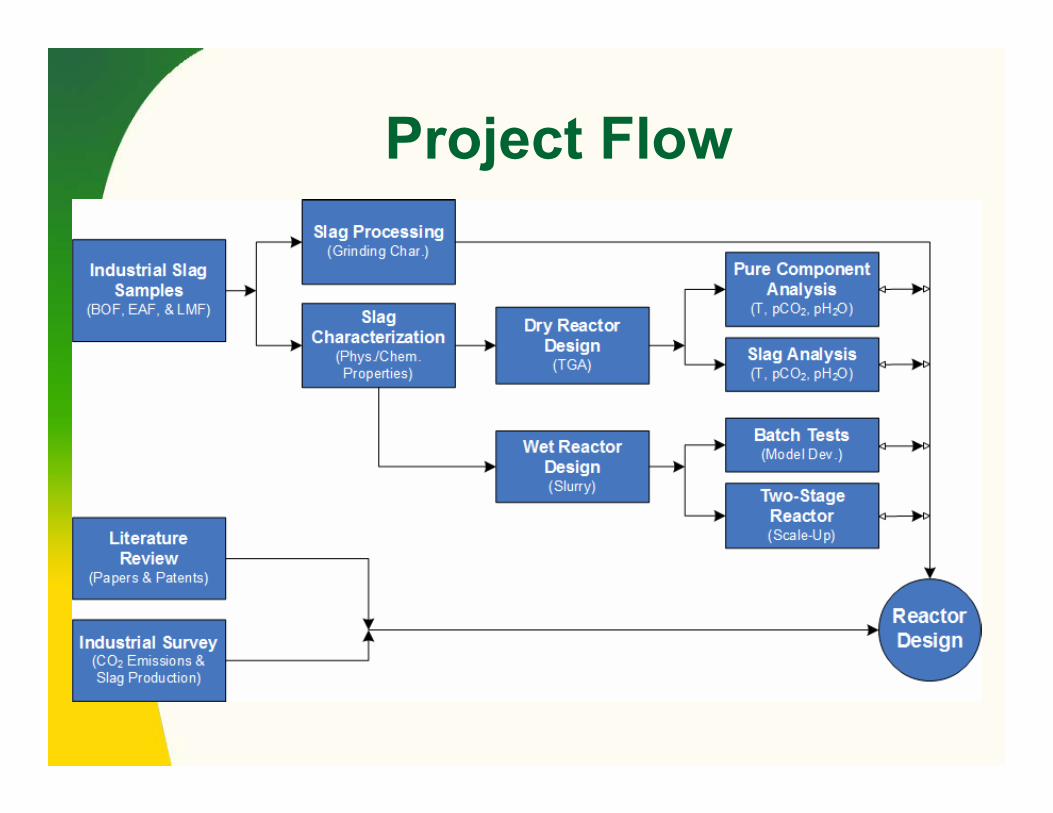
Project Flow
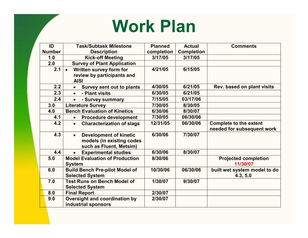
Work Plan
ID Number
Task/Subtask Milestone Description
Planned completion
Actual Completion
Comments
1.0 Kick-off Meeting 3/17/05 3/17/052.0 Survey of Plant Application
2.1 • Written survey form for review by participants and AISI
4/21/05 6/15/05
2.2 • Survey sent out to plants 4/30/05 6/21/05 Rev. based on plant visits2.3 • - Plant visits 6/30/05 6/21/052.4 • - Survey summary 7/15/05 03/17/06
3.0 Literature Survey 7/30/05 8/30/054.0 Bench Evaluation of Kinetics 6/30/06 8/30/07
4.1 • Procedure development 7/30/05 06/30/064.2 • Characterization of slags 12/31/05 06/30/06 Complete to the extent
needed for subsequent work 4.3 • Development of kinetic
models (in existing codes such as Fluent, Metsim)
6/30/06 7/30/07
4.4 • Experimental studies 6/30/06 8/30/075.0 Model Evaluation of Production
System 8/30/06 Projected completion
11/30/07 6.0 Build Bench Pre-pilot Model of
Selected System 10/30/06 06/30/06 built wet system model to do
4.3, 5.0 7.0 Test Runs on Bench Model of
Selected System 1/30/07 9/30/07
8.0 Final Report 2/30/079.0 Oversight and coordination by
industrial sponsors 2/30/07

Carbonate Forming Compounds in Slag (XRF)
Elements(as oxides)
EAFAvg. (8)
BOFAvg. (2)
LMF(Avg. 3)
CaO 32.44 40.71 49.43
MgO 11.20 12.90 6.23
FexOy 26.85 21.68 5.61
SiO2 13.95 11.65 12.96
Al2O3 8.29 5.93 21.26
MnO 5.37 4.59 1.06
TiO2 0.47 0.58 0.34
ZrO2 0.07 0.18 0.20
Cr2O3 1.48 0.36 0.25
K2O 0.05 B.L. 0.01
Na2O B.L. B.L. 0.01
CaO16.76 cm3
CaCO336.89 cm3
Ca(OH)233.08 cm3
ΔH°= -65.2 kJ ΔH°= -112.7 kJ
ΔV=97.4% ΔV=11.5%
ΔH°= -178.1 kJΔV=120.1%

Phase Identification (XRD)(major phases listed)
PDF# Formula MineralA1aEAF
A1bEAF
A1gLMF
B1aBOF
C1aBOF
D1aEAF
E1aEAF
E2aEAF
ΔH°(kJ)
Stability(°C)
Oxide77-2355 FeO Iron Oxide X X X X X74-1225 MgO Periclase X -116.7 40174-1226 CaO Calcium Oxide X -178.1 861Silicate83-0461 Ca2(SiO4) Larnite X X X -105.6 40183-0460 Ca2(SiO4) Larnite X -105.6 40177-0409 Ca2(SiO4) Calcium (di)Silicate X X -105.6 40170-0388 Ca2(SiO4) Calcium (di)Silicate X -105.6 40134-1350 Ca5MgSi3O12 Calcium Magnesium Silicate X - -31-0301 Ca3SiO5 Calcium (tri)Silicate X -141.0 58579-1726 Ca2Al2SiO7 Gehlenite X -113.4 644Aluminate78-0910 Ca12Al14O33 C12A7 X X X X - -82-0579 (Fe0.855Al0.145)(Al0.855Fe0.145)Hercynite (Synthetic) X N/A N.A.Ferrite77-2368 (MgO)0.432(FeO)0.568 Magnesium Iron Oxide X X X -51.0 307
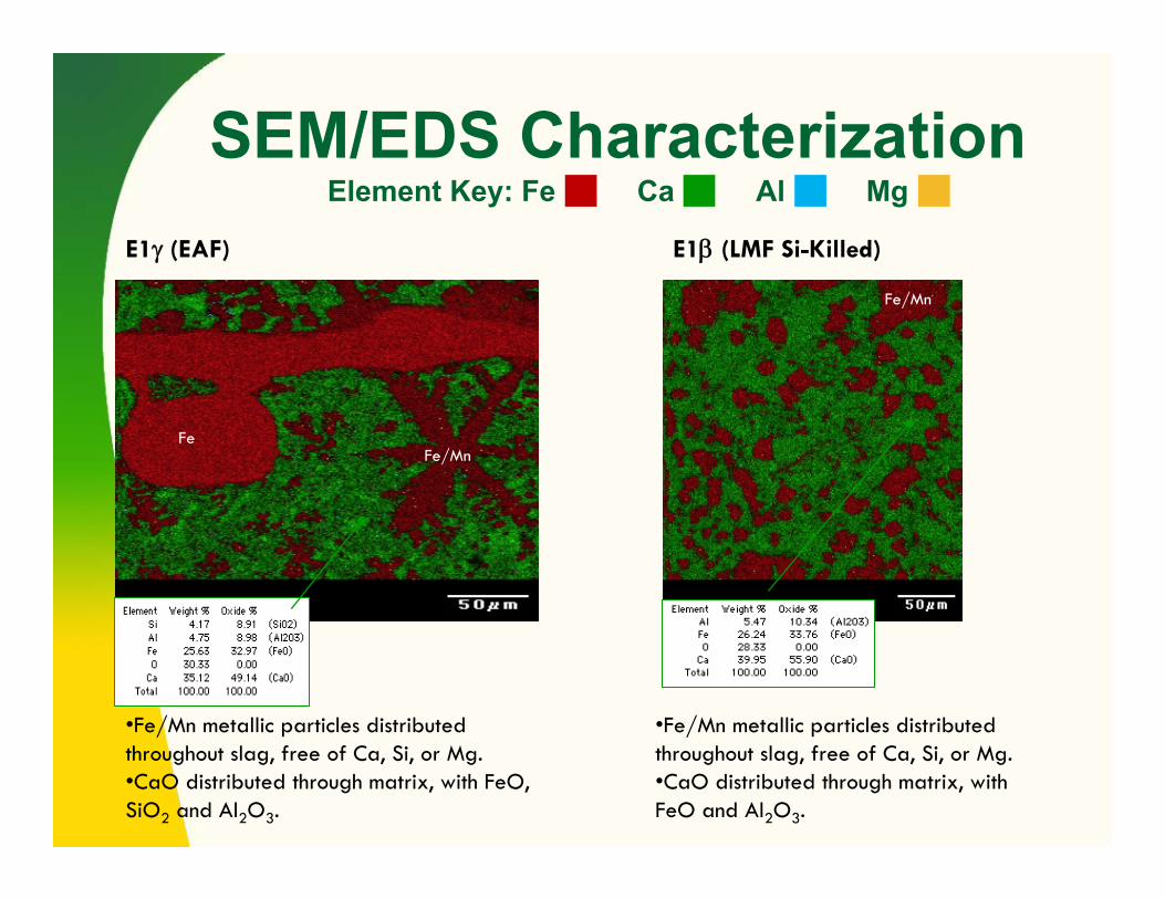
SEM/EDS CharacterizationElement Key: Fe Ca Al Mg
•Fe/Mn metallic particles distributed throughout slag, free of Ca, Si, or Mg.•CaO distributed through matrix, with FeO, SiO2 and Al2O3.
FeFe/Mn
E1γ (EAF) E1β (LMF Si-Killed)
Fe/Mn
•Fe/Mn metallic particles distributed throughout slag, free of Ca, Si, or Mg.•CaO distributed through matrix, with FeO and Al2O3.

•Fe/Mn metallic particles distributed throughout slag (10-50 μm), free of Ca, Si, or Mg.•CaO distributed through matrix, with a ~10mm particle of Al2O3.
E2γ (EAF) E2β (LMF Al-Killed)
Large blocks (100-500μm) of MgO spread throughout slag as discrete particles. •Small particles (5-25μm) of Al2O3 present.
Fe/Mn
Al2O3
MgO
SEM/EDS CharacterizationElement Key: Fe Ca Al Mg
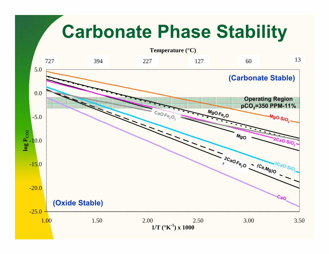
Carbonate Phase Stability
-25.0
-20.0
-15.0
-10.0
-5.0
0.0
5.0
1.00 1.50 2.00 2.50 3.00 3.501/T (°K-1) x 1000
log
P CO
2
1.00 1.50 2.00 2.50 3.00 3.50
Temperature (°C)
727 394 227 127 60 13
(Carbonate Stable)
(Oxide Stable)
Operating RegionpCO2=350 PPM-11%
MgO·SiO2
2CaO·SiO2
3CaO·SiO2
CaO
2CaO.Fe2O3 (Ca,Mg)O
MgO
CaO.Fe2O3
MgO.Fe2O3
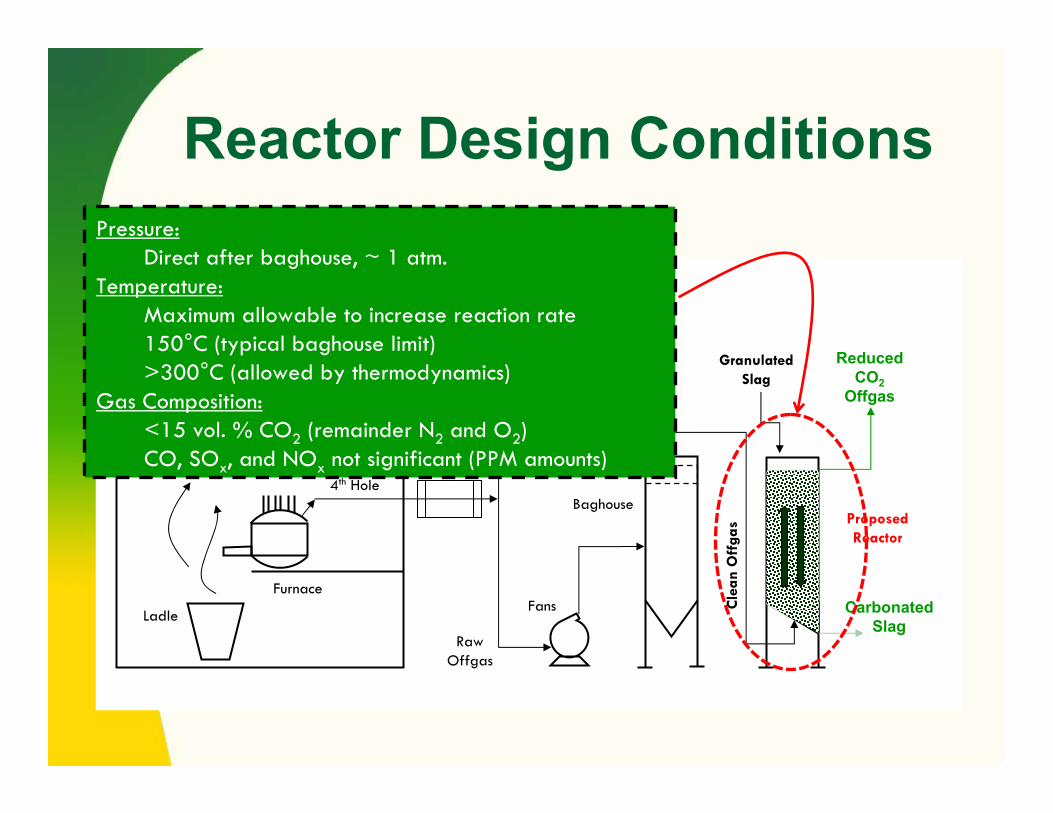
Reactor Design Conditions
Furnace
Ladle
CanopyHoods
4th Hole
Fans
Baghouse
Cle
an O
ffga
s
GranulatedSlag
ReducedCO2
Offgas
CarbonatedSlag
RawOffgas
Combust& Quench
ProposedReactor
(EAF Application Shown)Pressure:
Direct after baghouse, ~ 1 atm.Temperature:
Maximum allowable to increase reaction rate150°C (typical baghouse limit)>300°C (allowed by thermodynamics)
Gas Composition:<15 vol. % CO2 (remainder N2 and O2)CO, SOx, and NOx not significant (PPM amounts)
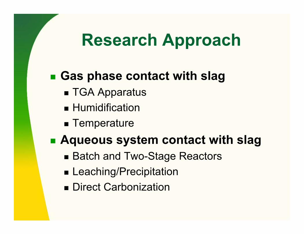
Research Approach
Gas phase contact with slagTGA ApparatusHumidificationTemperature
Aqueous system contact with slagBatch and Two-Stage ReactorsLeaching/PrecipitationDirect Carbonization

TGA ApparatusGas Metering
(Ar, CO2, N2, Air)0-10.00 l/min
GasHumidification
Tube FurnaceReactor
25-1100°C
Balance0.001g accuracy
Sample SuspendedIn Reactor
0-400g range
DAQ

TGA Reaction
CaO
Reacting Gas (CO2/H2O)
CO2H2O
CaO+CO2→CaCO3
Gel = CO32-/HCO3
-/Ca2+/H+/OH-
Furn
ace
Wal
l
Furn
ace
Wal
l

TGA Results
0
2
4
6
8
10
12
14
16
18
0 5000 10000 15000 20000
% Carbonated
Time (sec)
300°C Dry500°C Dry300°C Humid500°C Humid
CaO, anaerobic grade CO2, P=1atm
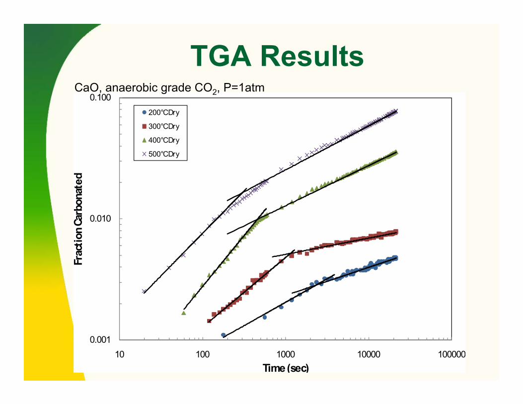
TGA Results
0.001
0.010
0.100
10 100 1000 10000 100000
Frac
tion C
arbo
nate
d
Time (sec)
200°C Dry
300°C Dry
400°C Dry
500°C Dry
CaO, anaerobic grade CO2, P=1atm

TGA ResultsSlag E1β, anaerobic grade CO2, P=1atm
0.0
0.2
0.4
0.6
0.8
1.0
0.0 1.0 2.0 3.0 4.0 5.0 6.0
% Carbonated
Time (hrs)
300°C Dry500°C Dry300°C Humid500°C Humid

Aqueous Sequestration
Description Reaction Ca leaching )(22
)()(2)(−+ +→+ OHCaOHCaO aqls
CO2 dissolution −+ +→+ 2)(3)(2)(2 2 aqlg COHOHCO
Carbonate precipitation )(3
2)(3
2)( saqaq CaCOCOCa →+ −+
Ca direct carbonization −− +=++ OHCaCOOHCOCaO slaqs 2)(3)(22
)(3)(
Water dissociation )(222)(2 lOHHOH →+ +−
Scenario 1: Fresh or recirculated water is supplied into Reactor 1, the leachate containing calcium ions is pumped to Reactor 2 in whichcalcium carbonate precipitates. The spent leachate (containing residual dissolved CO2) is discharged or recirculated into Reactor 1 after de-gasing.
Scenario 2: Recirculated solution is supplied to Reactor 2 for saturation with CO2, the CO2 saturated water is pumped to Reactor 1 for direct reaction with slag.
Pump
CleanedOffgas
Reactor 2
Reactor 1
StabilizedSlag
FreshSlag
Lower CO2
Offgas
WaterRecirculation
Loop
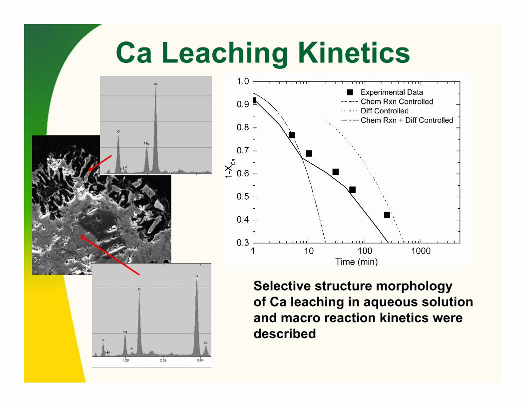
Ca Leaching Kinetics
Selective structure morphologyof Ca leaching in aqueous solution and macro reaction kinetics were described

Carbonization Kinetics
Modified shrinking core model was used for description of slag carbonization kinetics when product layer had different density and diffusivity
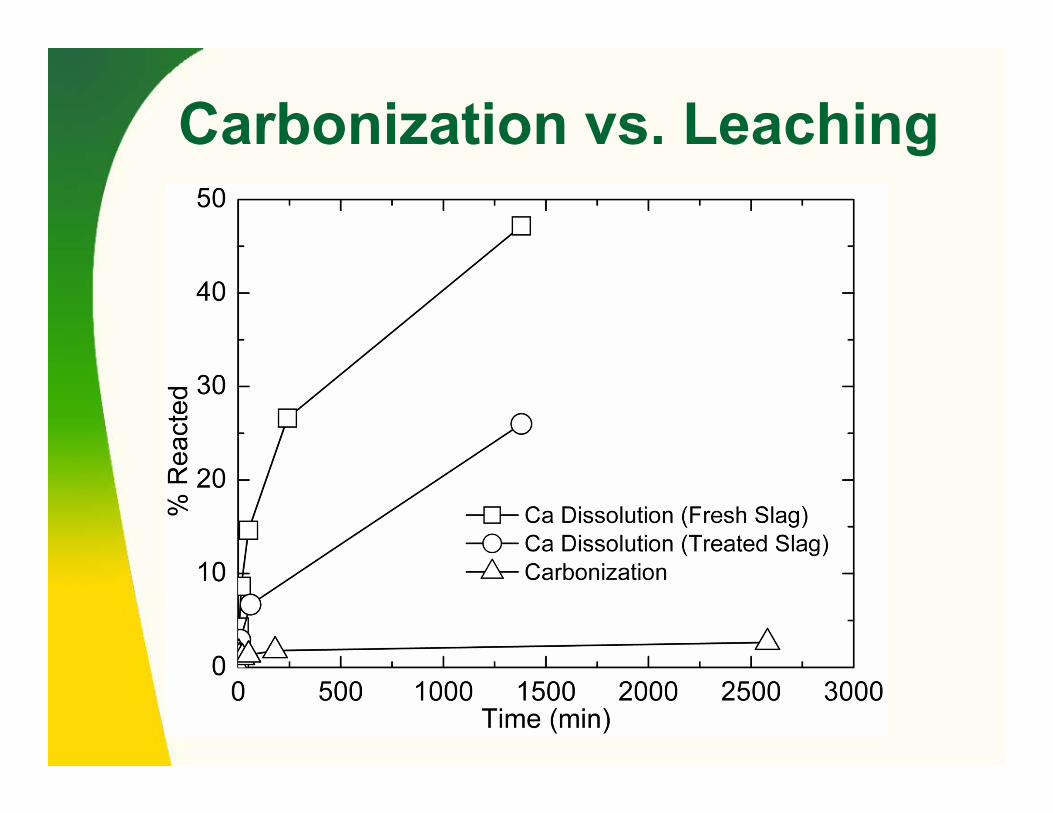
Carbonization vs. Leaching

Reactor Design
The different process scenarios were modeled and experimentally studied. The METSIM model developed can be used for the design of an optimized CO2 sequestration reactor system based on different slag fractions and compositions
Two interconnected reactors design gives the possibility for carbonization of existing industrial slag stream
Water out
CleanedOff-gas
Reactor 2Reactor 1
FreshSlag
StabilizedSlag
Lower CO2Off-gas
Pump
Water in

METSIM Model of Aqueous Process
F
H
G
L
M24
2526
27
19 FROM 15
TO 12 1816
17 21
20
22
A
B
C
D
E F1
8
432
75
3
10
6
FROM 20
TO 17119
12
13
14
15
Reactor 1 Reactor 2
Experimental 20 L reactor

Leaching and Precipitation(scenario one)
METSIM model shows that both increasing the slag/solution ratio and the solution residence time in Reactor 1 produces a higher concentration of
calcium ions in solution.
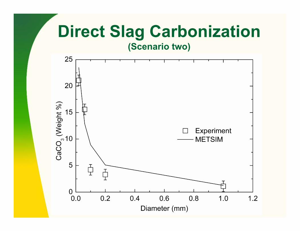
Direct Slag Carbonization (Scenario two)
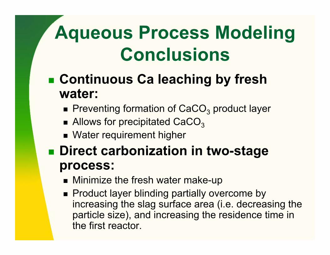
Aqueous Process Modeling Conclusions
Continuous Ca leaching by fresh water:
Preventing formation of CaCO3 product layerAllows for precipitated CaCO3Water requirement higher
Direct carbonization in two-stage process:
Minimize the fresh water make-upProduct layer blinding partially overcome by increasing the slag surface area (i.e. decreasing the particle size), and increasing the residence time in the first reactor.

Grinding: Metal Recovery & Sequestration Value
Slag Type
PowerCost ($/t)
CO2Cost($)
MetalValue($/t)
Sequest.Potent.
(kg CO2)
CO2 Tax Credit
($)
Net
EAF ($2.19) ($1.21) $18.85 13.7 $0.75 $16.21 BOF ($2.41) ($1.33) $21.64 25.9 $1.43 $19.32 LMF ($1.82) ($1.01) $9.44 4.0 $0.22 $6.83 Overall ($2.16) ($1.20) $17.55 23.7 $1.31 $15.50
Feed Rate=1000 kg/hr, F80=2.54cm, P80=100µmElectric=$0.07/kWh, Power Correction=1.50Metal Scrap Value=$300/tCO2 Tax=$0.025/lb @ 1.55 pounds CO2 per kWhSequestration Efficiency=50%
Publications1. Rawlins, C.H., Richards, V.L., Peaslee, K.D., and Lekakh, S.N., “Sequestration
of CO2 from Steelmaking Offgas by Carbonate Formation with Slag,” AISTech 2006 Proceedings, Vol. II, 2006, pp. 1133-1144.
2. Rawlins, C.H., Richards, V.L., Peaslee, K.D., and Lekakh, S.N., “Steelmaking Slag as a Permanent Sequestration Sink for Carbon Dioxide,” Steel Times International, Vol. 30, No. 7, October 2006, pp. 25-28.
3. Rawlins, C.H, Richards, V.L., Peaslee, K.D., and Lekakh, S.N., “Experimental Study of CO2 Sequestration by Steelmaking Slag,” TMS2007 Materials Process Fundamentals, Edited by P. Anyalebechi, TMS, 2007, pp. 193-202.
4. Rawlins, C.H., Lekakh, S.N., Richards, V.L., and Peaslee, K.D., “The Use of Steelmaking Slag for Mineralogical Sequestration of Carbon Dioxide-Aqueous Processing,” AISTech 2007, Vol. II, 2007.
5. Rawlins, C.H., Lekakh, S.N., Richards, V.L., and Peaslee, K.D., “Mineralogical Sequestration of Carbon Dioxide through Aqueous Processing of Steelmaking Slag,” MS&T’07, 2007.
6. Lekakh, S.N., Rawlins, C.H., Robertson, D.R., Richards, V.L., and Peaslee, K.D., “Aqueous Leaching and Carbonization of Steelmaking Slag for Geological Sequestration of Carbon Dioxide,” Metallurgical and Materials Transactions B, manuscript accepted with required revisions Sept. 2007.

Projected deployment
Assuming second phase for development 2008-2010Deployment in production could occur between 2012 and 2017 because it uses a current co-product and has some economic benefit

Future Work
Catalytic AccelerationMicroscale modeling of heterogenous multiphase reaction with synthetic slagEvaluation of cooling rate and glassy phase effectsMicroscale optimization
GrindingIron recoveryCO2 SequestrationSlag processing

Acknowledgement
DOFASCOGallatin SteelHylsaUS SteelArcelorMittal Steel
PraxairNucor Timken Co.IPSCO
•U.S. Dept. of Energy and AISI for their financial sponsorship
•Corporate Partners: