CNSS Work package 4, Showcase LNG LNG fuelled ships as...
80
CNSS Work package 4, Showcase LNG LNG fuelled ships as a contribution to clean air in harbours CNSS May 2013
Transcript of CNSS Work package 4, Showcase LNG LNG fuelled ships as...
CNSS Work package 4, Showcase LNG
LNG fuelled ships as a contribution to clean air in harbours
CNSS
May 2013
2
LNG FUELLED SHIPS AS A CONTRIBUTION TO CLEAN AIR IN HARBOURS
1 Introduction 41.1 Clean North Sea Shipping 41.2 LNG showcase 41.3 Main contributors 41.4 Report structure 41.5 Limitations 41.6 Abbreviations and definitions 5
2 Summary 73 LNG supply chain 8
3.1 Introduction 83.2 LNG Source 103.3 Intermediate terminal 113.4 Bunker vessel 123.5 Feeder vessel 123.6 LNG Truck 133.7 LNG Pipeline 133.8 Receiving vessels 13
4 LNG stakeholders demands 154.1 Introduction 154.2 Ship owners/operators 154.3 Policy makers 154.4 Authorities 164.5 Ports 164.6 Terminal operators 164.7 LNG suppliers 164.8 Others 17
5 Existing and future regulations, standards and legislations 185.1 Regulations for marine activities 185.2 Ship-to-shore and ship-to-ship transfer standards 195.3 Global initiatives by involved parties 205.4 Regulations for onshore activities 215.5 Regulations for transporting LNG via inland ship-based activities 225.6 Conclusion 23
6 Bunkering procedures 246.1 Present status 246.2 On-going international developments 246.3 National initiatives and solutions 246.4 Conclusion 25
7 Bunkering and navigational safety evaluation 267.1 Introduction 267.2 HAZID 267.3 Traffic analysis 307.4 Quantitative risk assessment 317.5 Collision rates for a realistic scenario 327.6 Conclusion 33
8 Health and environmental aspects 348.1 Definition of LNG 348.2 Impact on the operation of machinery onboard ships 348.3 Health effects and risk potential 348.4 Comparison of alternative fuels 358.5 Global effects 378.6 A local emission scenario for the city of Hamburg based on the replacement
of oil-based fuels by LNG 378.7 Summary 39
Table of Contents
3
9 LNG Market overview 409.1 The history of LNG 409.2 Increase in availability 409.3 Regional pricing imbalance 429.4 Price development in the future 439.5 Conclusion 43
10 Cost-benefit analysis 4410.1 Introduction 4410.2 Investment costs for LNG-fuelled ships 4810.3 LNG fuel supply infrastructure 49
11 Knowledge, training and certification 5111.1 Crew on IGF vessels 5111.2 Bunker vessels crew 5211.3 Inland water way shipping 5311.4 Shore based LNG supply professionals 5411.5 Directly related professionals 5411.6 Authorities 55
12 Brunsbüttel – Establishing an LNG terminal for the North and Baltic Sea areas 5612.1 Project background 5612.2 Abstract 5612.3 LNG supply chain 5712.4 Alternative terminal concepts 5912.5 Potential market for LNG as fuel in the showcase 6012.6 Preparations for the application 6212.7 Evaluation of bunkering procedures 6312.8 Risk and Safety screening in Brunsbüttel 6412.9 Pilot study 6812.10 Bunkering in Brunsbüttel 70
13 Findings 7413.1 Regulatory 7413.2 Commercial 7413.3 Environmental 7513.4 Education, training and certification 75
References 76Appendices 79
Appendix A LNG Bunkering from Bunker vessel in port of HamburgAppendix B Navigational Safety Study on LNG-Tanker and LNG-Bunker Supply Vessel
operation at Port of HamburgAppendix C Rules and regulations of the report modalities for the provisioning of LNG as
shipping fuel in Flemish ports
Photo: Deen Shipping
4
LNG FUELLED SHIPS AS A CONTRIBUTION TO CLEAN AIR IN HARBOURS
1 Introduction
1.1 Clean North Sea Shipping
The Clean North Sea Shipping (CNSS) project,involving 18 partners from six countries, seeks toaddress the problems caused by air pollution andgreenhouse gases produced by ships operating alongthe North Sea coast and within North Sea ports andharbours. A reduction in exhaust gas emissions fromships will improve the general environmental situationin the North Sea Region.The CNSS project aims to create awareness, shareknowledge and convince influential stakeholders,including regional and European politicians, ports,shipping companies and cargo owners, to take action.
1.2 LNG showcase
This report is the result of one of the activities of theWP4 Clean Shipping Technology work package calledthe LNG (Liquefied Natural Gas) showcase. The mainpurpose of the showcase is to increase awareness andunderstanding among policy makers and otherstakeholders of gas-fuelled ships as a potential CleanShipping Technology. The showcase report will provide an introduction toLNG or biogas as an alternative fuel for ships andanswer most of the questions that the stakeholdersmight have relating to this technology.
1.3 Main contributors
The main contributors to this report are as follows:
Chapter Main contributor
1 White Smoke Consulting on behalf ofHordaland County Council
2 White Smoke Consulting on behalf ofHordaland County Council
3 Swedish Marine Technology Forum
4 Swedish Marine Technology Forum
5 Port of Antwerp
6 Germanischer Lloyd
7 Germanischer Lloyd
8 BSU Hamburg together with Helmholtz-Zentrum Geesthacht
9 White Smoke Consulting on behalf ofHordaland County Council
10 White Smoke Consulting on behalf ofHordaland County Council
11 White Smoke Consulting on behalf ofHordaland County Council
12 GASNOR
13 White Smoke Consulting on behalf ofHordaland County Council
Groningen Seaports and the Port of Harlingen areacknowledged for their contribution at different stagesof the report compilation. The Port of Gothenburg andMaritime Kompetenzzentrum in Leer (MARIKO) arealso acknowledged for their contribution andparticipation in the early stages of the WP4 workpackage of the CNSS project.
1.4 Report structure
The report is structured as follows:• Chapter 1 and 2 provide an introduction to, and a
summary of, the main issues.• Chapters 3 to 11 highlight specific aspects of the
introduction of LNG as marine fuel and provide anoverview of each topic. For those interested infinding out more about some of the topicsdiscussed, references to further sources ofinformation are provided throughout the report. Forchapter 5 and 7, supplementary information isavailable in the appendices.
• Chapter 12 illustrates many of the topicsdiscussed in the preceding chapters with aspecific reference case—the Gasnor LNGbunkering facility establishment in the port ofBrunsbüttel, close to the North Sea entrance of theKiel Canal and the main entrance to the Port ofHamburg.
• Chapter 13 concludes the report withrecommendation for different stakeholdersprovided by the participants in the LNG showcasework.
1.5 Limitations
The purpose of this showcase report is to provide aninsight into most, if not all, of the topics to beaddressed when considering LNG bunkering and toprovide additional references for further information.This report will not contain detailed information, nor willit provide complete guidelines on establishing andoperating LNG bunkering.
5
1.6 Abbreviations and definitions
AND International Carriage of Dangerous
Goods by Inland Waterways
ADR International Carriage of Dangerous
Goods by Road
AIS Automatic Identification System
API American Petroleum Institute
BLG International Maritime Organisation (IMO)
sub-committee dealing with Bulk Liquids
and Gases
BOE Barrel of oil equivalent
CCNR Central Commission for the Navigation of
the Rhine
CEN European Committee for Standardization
CFR Code of Federal Regulations
CNG Compressed natural gas
CH4 Methane
CO2 Carbon dioxide
DMA Danish Maritime Authority
ECA Emission Control Area
EGR Exhaust gas recirculation
EIA Environmental Impact Assessment
EMSA European Maritime Safety Agency
ESD Emergency Shut Down
ESPO European Sea Ports Organization
EU European Union
Flemish
Study Solutions for the provision of LNG as
shipping fuel in Flemish ports
Fracking A method to extract shale natural gas
(NG) from flaky shale rock
FOB Free On Board (as defined in the
Incoterms 2010 by the International
Chamber of Commerce)
GHG Greenhouse Gas. Emissions of gaseous
substances that trap heat in the
atmosphere and contribute to the Green
House effect and climate change.
GJ Giga Joule
GL Germanischer Lloyd
HA Hazardous Area. An area in which an
explosive gas atmosphere is present, or
may be expected to be present, in
quantities such as to require special
precautions for the construction,
installation and use of apparatus. [ISO
18132-2:2008, 3.3]
HAZID Hazard Identification
HFO Heavy Fuel Oil
IAPH International Association of Ports and
Harbours
IEA International Energy Agency
IGC International Code For The Construction
And Equipment Of Ships Carrying
Liquefied Gases In Bulk
IGF Code International Code of Safety for Ships
Using Gases or other Low Flashpoint
Fuels (draft)
IGF vessel A vessel using LNG as main fuel designed
and operated for international trade in line
with the IMO regulations
IGO Intergovernmental organization
IMDG International Maritime Dangerous Goods
Code
IMO International Maritime Organisation
ISGINTT International Safety Guide for Inland
Navigation Tank-barges and Terminals
ISGOTT International Safety Guide for Oil Tankers
and Terminals
ISO International Organization for
Standardization
6
LNG FUELLED SHIPS AS A CONTRIBUTION TO CLEAN AIR IN HARBOURS
IWS Inland waterway shipping
Liquefied A tanker that transport liquefied gases
gas such as LNG, LPG, Ethylene, Carbon
tankers Dioxide and so on.
LNG Liquefied Natural Gas
LPG Liquefied Petroleum Gas
MGO Marine Gas Oil
MARPOL International Convention for the Prevention
of Pollution from Ships
MGO Marine Gas Oil
MOW Mobiliteit en Openbare Werken (Flemish
Department of Mobility and Public Work)
NaOH Sodium hydroxide (also known as lye or
caustic soda)
Natural gasA hydrocarbon gas mixture consisting
mainly of methane. The composition of the
gas may also include varying amounts of
nitrogen, carbon dioxide and so on.
NFPA National Fire Protection Association
NG Natural gas
NGO Non-governmental organization
NOx Nitrogen oxides
OCIMF Oil Companies International Marine Forum
PM Particulate matter
PSV Platform supply vessel
QCDC Quick Connect Disconnect
RPT Rapid phase transition
RVIR Rhine Vessel Inspection Regulations
SAR Search and rescue
SCR Selective Catalytic Reduction
SECA Sulphur Emission Control Area
SIGTTO Society of International Gas Tanker &
Terminal Operators
SO2 Sulphur dioxide
SOLAS International Convention for the Safety of
Life at Sea
SOx Sulphur oxides
STCW International Convention on Standards of
Training, Certification, and Watchkeeping
for Seafarers
STW IMO sub-committee dealing with
Standards of Training and Watchkeeping
UN United Nations
UNECE United Nations Economic Commission for
Europe
WPCI World Port Climate Initiative
7
2 Summary
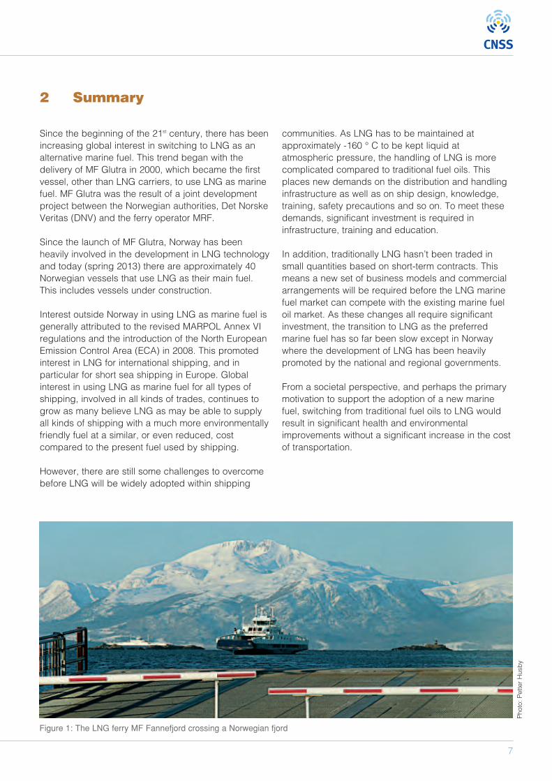
Since the beginning of the 21st century, there has beenincreasing global interest in switching to LNG as analternative marine fuel. This trend began with thedelivery of MF Glutra in 2000, which became the firstvessel, other than LNG carriers, to use LNG as marinefuel. MF Glutra was the result of a joint developmentproject between the Norwegian authorities, Det NorskeVeritas (DNV) and the ferry operator MRF.
Since the launch of MF Glutra, Norway has beenheavily involved in the development in LNG technologyand today (spring 2013) there are approximately 40Norwegian vessels that use LNG as their main fuel.This includes vessels under construction.
Interest outside Norway in using LNG as marine fuel isgenerally attributed to the revised MARPOL Annex VIregulations and the introduction of the North EuropeanEmission Control Area (ECA) in 2008. This promotedinterest in LNG for international shipping, and inparticular for short sea shipping in Europe. Globalinterest in using LNG as marine fuel for all types ofshipping, involved in all kinds of trades, continues togrow as many believe LNG as may be able to supplyall kinds of shipping with a much more environmentallyfriendly fuel at a similar, or even reduced, costcompared to the present fuel used by shipping.
However, there are still some challenges to overcomebefore LNG will be widely adopted within shipping
communities. As LNG has to be maintained atapproximately -160 ° C to be kept liquid atatmospheric pressure, the handling of LNG is morecomplicated compared to traditional fuel oils. Thisplaces new demands on the distribution and handlinginfrastructure as well as on ship design, knowledge,training, safety precautions and so on. To meet thesedemands, significant investment is required ininfrastructure, training and education.
In addition, traditionally LNG hasn’t been traded insmall quantities based on short-term contracts. Thismeans a new set of business models and commercialarrangements will be required before the LNG marinefuel market can compete with the existing marine fueloil market. As these changes all require significantinvestment, the transition to LNG as the preferredmarine fuel has so far been slow except in Norwaywhere the development of LNG has been heavilypromoted by the national and regional governments.
From a societal perspective, and perhaps the primarymotivation to support the adoption of a new marinefuel, switching from traditional fuel oils to LNG wouldresult in significant health and environmentalimprovements without a significant increase in the costof transportation.
Figure 1: The LNG ferry MF Fannefjord crossing a Norwegian fjord
Photo: Petter Husby
8
LNG FUELLED SHIPS AS A CONTRIBUTION TO CLEAN AIR IN HARBOURS
3.1 Introduction
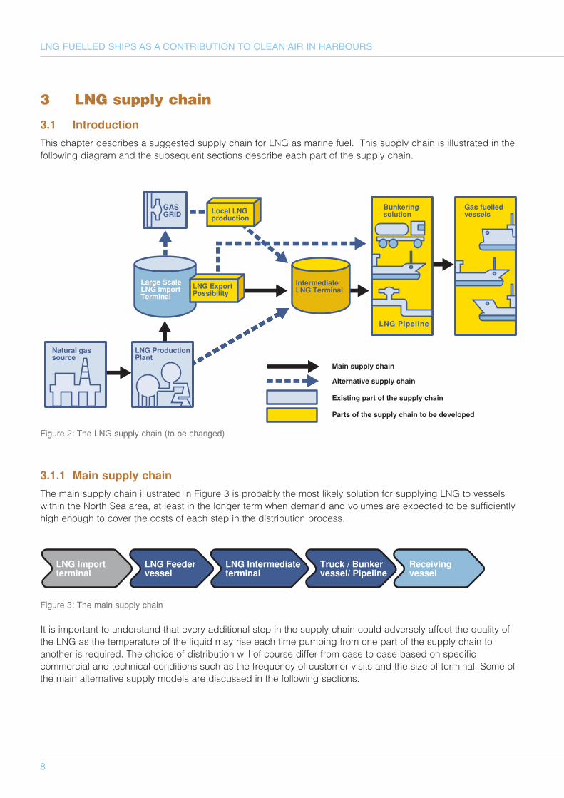
This chapter describes a suggested supply chain for LNG as marine fuel. This supply chain is illustrated in thefollowing diagram and the subsequent sections describe each part of the supply chain.
3.1.1 Main supply chain
The main supply chain illustrated in Figure 3 is probably the most likely solution for supplying LNG to vesselswithin the North Sea area, at least in the longer term when demand and volumes are expected to be sufficientlyhigh enough to cover the costs of each step in the distribution process.
Figure 3: The main supply chain
It is important to understand that every additional step in the supply chain could adversely affect the quality ofthe LNG as the temperature of the liquid may rise each time pumping from one part of the supply chain toanother is required. The choice of distribution will of course differ from case to case based on specificcommercial and technical conditions such as the frequency of customer visits and the size of terminal. Some ofthe main alternative supply models are discussed in the following sections.
3 LNG supply chain
Large ScaleLNG ImportTerminal
LNG ExportPossibility
GASGRID
IntermediateLNG Terminal
Gas fuelledvessels
Natural gassource
LNG ProductionPlant
Bunkeringsolution
LNG Pipeline
Main supply chain
Alternative supply chain
Existing part of the supply chain
Parts of the supply chain to be developed
Local LNGproduction
Figure 2: The LNG supply chain (to be changed)
LNG Importterminal
LNG Feedervessel
LNG Intermediateterminal
Truck / Bunkervessel/ Pipeline
Receivingvessel
9
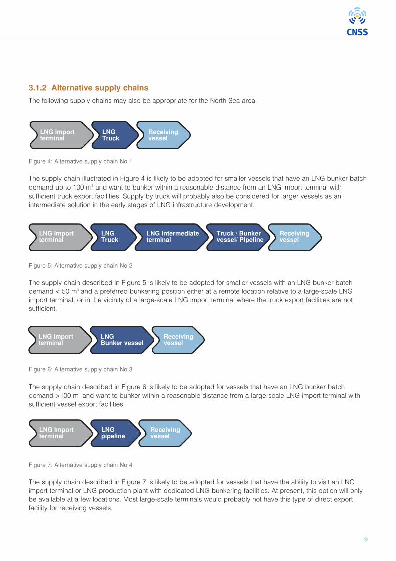
3.1.2 Alternative supply chains
The following supply chains may also be appropriate for the North Sea area.
Figure 4: Alternative supply chain No 1
The supply chain illustrated in Figure 4 is likely to be adopted for smaller vessels that have an LNG bunker batchdemand up to 100 m3 and want to bunker within a reasonable distance from an LNG import terminal withsufficient truck export facilities. Supply by truck will probably also be considered for larger vessels as anintermediate solution in the early stages of LNG infrastructure development.
Figure 5: Alternative supply chain No 2
The supply chain described in Figure 5 is likely to be adopted for smaller vessels with an LNG bunker batchdemand < 50 m3 and a preferred bunkering position either at a remote location relative to a large-scale LNGimport terminal, or in the vicinity of a large-scale LNG import terminal where the truck export facilities are notsufficient.
Figure 6: Alternative supply chain No 3
The supply chain described in Figure 6 is likely to be adopted for vessels that have an LNG bunker batchdemand >100 m3 and want to bunker within a reasonable distance from a large-scale LNG import terminal withsufficient vessel export facilities.
Figure 7: Alternative supply chain No 4
The supply chain described in Figure 7 is likely to be adopted for vessels that have the ability to visit an LNGimport terminal or LNG production plant with dedicated LNG bunkering facilities. At present, this option will onlybe available at a few locations. Most large-scale terminals would probably not have this type of direct exportfacility for receiving vessels.
LNG Importterminal
LNGTruck
Receivingvessel
LNG Importterminal
Receivingvessel
LNG Intermediateterminal
Truck / Bunkervessel/ Pipeline
LNGTruck
LNG Importterminal
Receivingvessel
LNGBunker vessel
LNG Importterminal
Receivingvessel
LNGpipeline
10
LNG FUELLED SHIPS AS A CONTRIBUTION TO CLEAN AIR IN HARBOURS
In addition to the supply chain alternatives describehere, the following technologies could also becomepotential supply solutions for gas-fuelled vessels incertain situations:
• LNG by local liquefaction from NG-pipeline• Container/trailer tank distribution—For example
RoRo (Roll-on, Roll-off) vessels• Compressed natural gas (CNG)—For example
smaller vessels such as commuter ferries
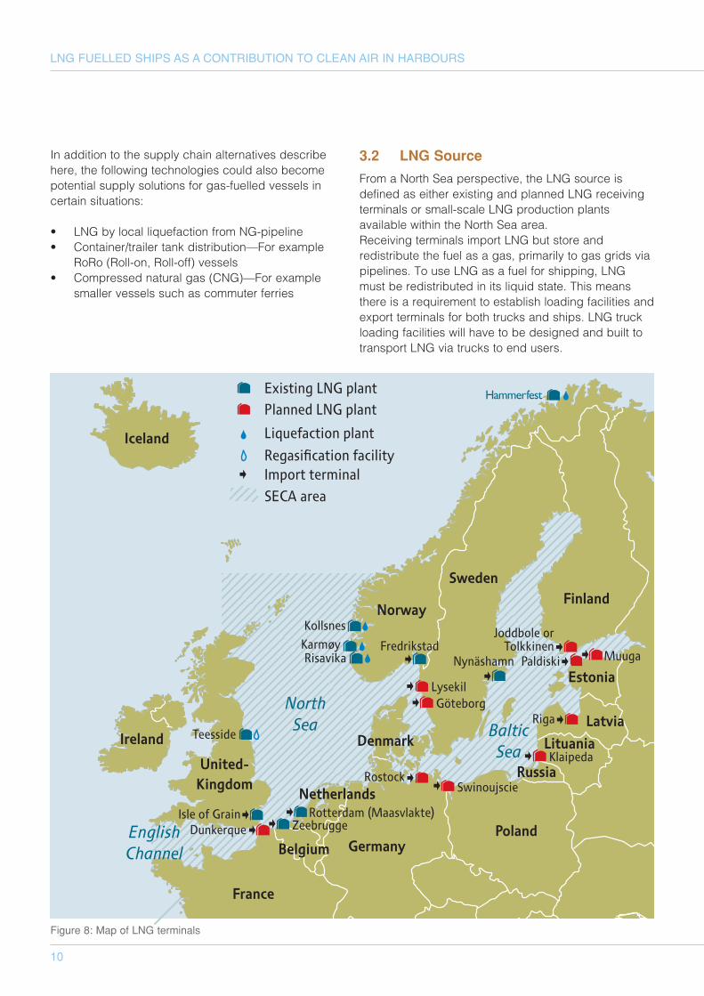
3.2 LNG Source
From a North Sea perspective, the LNG source isdefined as either existing and planned LNG receivingterminals or small-scale LNG production plantsavailable within the North Sea area.Receiving terminals import LNG but store andredistribute the fuel as a gas, primarily to gas grids viapipelines. To use LNG as a fuel for shipping, LNGmust be redistributed in its liquid state. This meansthere is a requirement to establish loading facilities andexport terminals for both trucks and ships. LNG truckloading facilities will have to be designed and built totransport LNG via trucks to end users.
Figure 8: Map of LNG terminals
11
LNG vessel loading and export terminals will also berequired. It is vital that the new export facilities do notinterfere with the operations of the import terminal, andthat both import and export terminals can operateindependently.
The size of ships that will load LNG at an exportterminal may vary. There will probably be both LNGBunker and Feeder vessels loading at the exportfacility. Ideally other types of LNG fuelled vesselscould also be using the facilities to bunker LNG.The design of export terminals for both trucks andvessels should also take possible future expansion intoconsideration.
3.3 Intermediate terminal
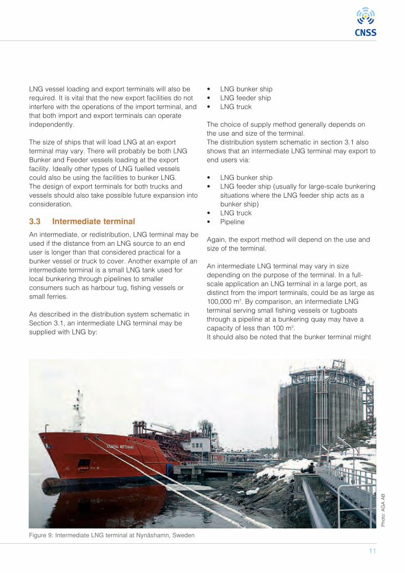
An intermediate, or redistribution, LNG terminal may beused if the distance from an LNG source to an enduser is longer than that considered practical for abunker vessel or truck to cover. Another example of anintermediate terminal is a small LNG tank used forlocal bunkering through pipelines to smallerconsumers such as harbour tug, fishing vessels orsmall ferries.
As described in the distribution system schematic inSection 3.1, an intermediate LNG terminal may besupplied with LNG by:
• LNG bunker ship• LNG feeder ship• LNG truck
The choice of supply method generally depends onthe use and size of the terminal.The distribution system schematic in section 3.1 alsoshows that an intermediate LNG terminal may export toend users via:
• LNG bunker ship• LNG feeder ship (usually for large-scale bunkering
situations where the LNG feeder ship acts as abunker ship)
• LNG truck• Pipeline
Again, the export method will depend on the use andsize of the terminal.
An intermediate LNG terminal may vary in sizedepending on the purpose of the terminal. In a full-scale application an LNG terminal in a large port, asdistinct from the import terminals, could be as large as100,000 m3. By comparison, an intermediate LNGterminal serving small fishing vessels or tugboatsthrough a pipeline at a bunkering quay may have acapacity of less than 100 m3.It should also be noted that the bunker terminal might
Figure 9: Intermediate LNG terminal at Nynäshamn, Sweden
Photo: AGA AB
be a barge or ship serving as an intermediate terminal.In this case, a bunker vessel as well as an LNG-fuelledship will be able to moor alongside and bunker LNG.
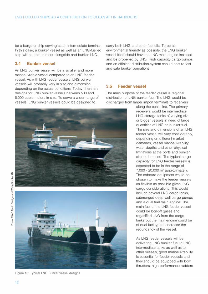
3.4 Bunker vessel
An LNG bunker vessel will be a smaller and moremanoeuvrable vessel compared to an LNG feedervessel. As with LNG feeder vessels, LNG bunkervessels will probably vary in size and dimensiondepending on the actual conditions. Today, there aredesigns for LNG bunker vessels between 500 and6,000 cubic meters in size. To serve a wider range ofvessels, LNG bunker vessels could be designed to
carry both LNG and other fuel oils. To be asenvironmental friendly as possible, the LNG bunkervessel itself should have an LNG main engine installedand be propelled by LNG. High capacity cargo pumpsand an efficient distribution system should ensure fastand safe bunker operations.
3.5 Feeder vessel
The main purpose of the feeder vessel is regionaldistribution of LNG bunker fuel. The LNG would bedischarged from larger import terminals to receivers
along the coast line. The primaryreceivers would be intermediateLNG storage tanks of varying size,or bigger vessels in need of largequantities of LNG as bunker fuel.The size and dimensions of an LNGfeeder vessel will vary considerably,depending on different marketdemands, vessel manoeuvrability,water depths and other physicallimitations at the ports and bunkersites to be used. The typical cargocapacity for LNG feeder vessels isexpected to be in the range of7,000 - 20,000 m3 approximately.The onboard equipment would bechosen to make the feeder vesselsas flexible as possible given LNGcargo considerations. This wouldinclude several LNG cargo tanks,submerged deep-well cargo pumpsand a dual fuel main engine. Themain fuel of the LNG feeder vesselcould be boil-off gases andregasified LNG from the cargotanks but the main engine could beof dual fuel type to increase theredundancy of the vessel.
As LNG feeder vessels will bedelivering LNG bunker fuel to LNGintermediate tanks as well as toother vessels, good manoeuvrabilityis essential for feeder vessels andthey should be equipped with bowthrusters, high performance rudders
12
LNG FUELLED SHIPS AS A CONTRIBUTION TO CLEAN AIR IN HARBOURSPhoto: FKAB Marin Design and White Smoke AB
Figure 10: Typical LNG Bunker vessel designs
13
and so on. LNG feeder vessels should beeasy to operate during coastal navigation andmooring operations to minimise the use ofharbour tugs to perform bunker operations.
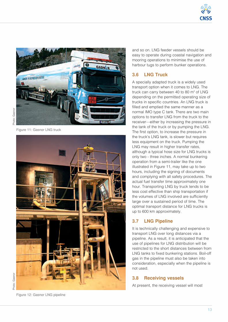
3.6 LNG Truck
A specially adapted truck is a widely usedtransport option when it comes to LNG. Thetruck can carry between 40 to 80 m3 of LNGdepending on the permitted operating size oftrucks in specific countries. An LNG truck isfilled and emptied the same manner as anormal IMO type C tank. There are two mainoptions to transfer LNG from the truck to thereceiver—either by increasing the pressure inthe tank of the truck or by pumping the LNG.The first option, to increase the pressure inthe truck's LNG tank, is slower but requiresless equipment on the truck. Pumping theLNG may result in higher transfer rates,although a typical hose size for LNG trucks isonly two - three inches. A normal bunkeringoperation from a semi-trailer like the oneillustrated in Figure 11, may take up to twohours, including the signing of documentsand complying with all safety procedures. Theactual fuel transfer time approximately onehour. Transporting LNG by truck tends to beless cost effective than ship transportation ifthe volumes of LNG involved are sufficientlylarge over a sustained period of time. Theoptimal transport distance for LNG trucks isup to 600 km approximately.
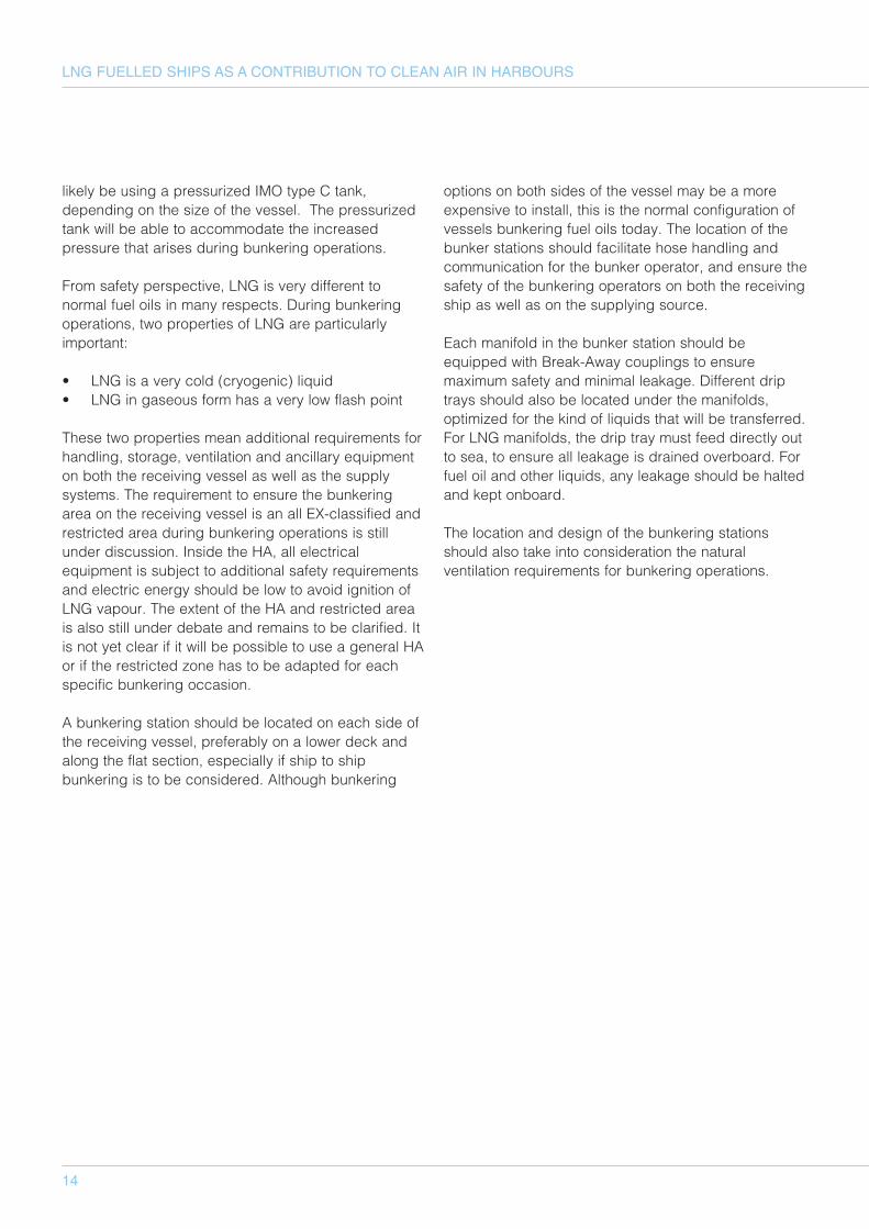
3.7 LNG Pipeline
It is technically challenging and expensive totransport LNG over long distances via apipeline. As a result, it is anticipated that theuse of pipelines for LNG distribution will berestricted to the short distances between fromLNG tanks to fixed bunkering stations. Boil-offgas in the pipeline must also be taken intoconsideration, especially when the pipeline isnot used.
3.8 Receiving vessels
At present, the receiving vessel will most
Photo: G
asnor
Photo: G
asnor
Figure 11: Gasnor LNG truck
Figure 12: Gasnor LNG pipeline
14
LNG FUELLED SHIPS AS A CONTRIBUTION TO CLEAN AIR IN HARBOURS
likely be using a pressurized IMO type C tank,depending on the size of the vessel. The pressurizedtank will be able to accommodate the increasedpressure that arises during bunkering operations.
From safety perspective, LNG is very different tonormal fuel oils in many respects. During bunkeringoperations, two properties of LNG are particularlyimportant:
• LNG is a very cold (cryogenic) liquid • LNG in gaseous form has a very low flash point
These two properties mean additional requirements forhandling, storage, ventilation and ancillary equipmenton both the receiving vessel as well as the supplysystems. The requirement to ensure the bunkeringarea on the receiving vessel is an all EX-classified andrestricted area during bunkering operations is stillunder discussion. Inside the HA, all electricalequipment is subject to additional safety requirementsand electric energy should be low to avoid ignition ofLNG vapour. The extent of the HA and restricted areais also still under debate and remains to be clarified. Itis not yet clear if it will be possible to use a general HAor if the restricted zone has to be adapted for eachspecific bunkering occasion.
A bunkering station should be located on each side ofthe receiving vessel, preferably on a lower deck andalong the flat section, especially if ship to shipbunkering is to be considered. Although bunkering
options on both sides of the vessel may be a moreexpensive to install, this is the normal configuration ofvessels bunkering fuel oils today. The location of thebunker stations should facilitate hose handling andcommunication for the bunker operator, and ensure thesafety of the bunkering operators on both the receivingship as well as on the supplying source.
Each manifold in the bunker station should beequipped with Break-Away couplings to ensuremaximum safety and minimal leakage. Different driptrays should also be located under the manifolds,optimized for the kind of liquids that will be transferred.For LNG manifolds, the drip tray must feed directly outto sea, to ensure all leakage is drained overboard. Forfuel oil and other liquids, any leakage should be haltedand kept onboard.
The location and design of the bunkering stationsshould also take into consideration the naturalventilation requirements for bunkering operations.
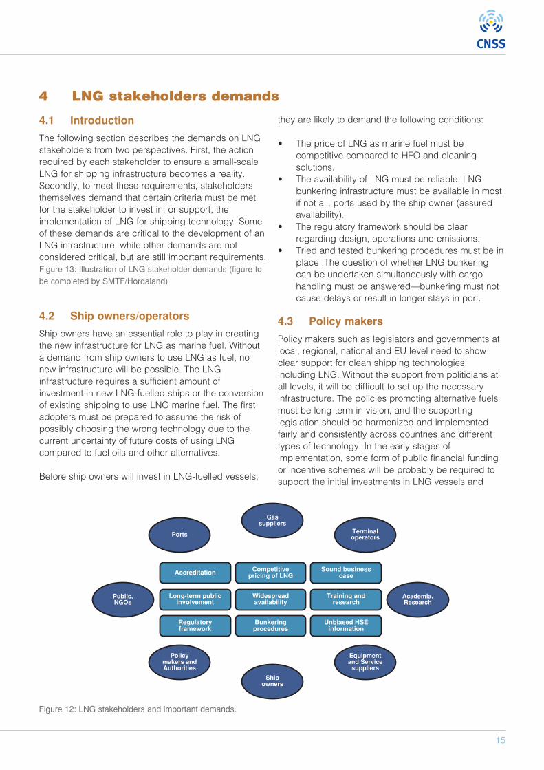
4.1 Introduction
The following section describes the demands on LNGstakeholders from two perspectives. First, the actionrequired by each stakeholder to ensure a small-scaleLNG for shipping infrastructure becomes a reality.Secondly, to meet these requirements, stakeholdersthemselves demand that certain criteria must be metfor the stakeholder to invest in, or support, theimplementation of LNG for shipping technology. Someof these demands are critical to the development of anLNG infrastructure, while other demands are notconsidered critical, but are still important requirements.Figure 13: Illustration of LNG stakeholder demands (figure tobe completed by SMTF/Hordaland)
4.2 Ship owners/operators
Ship owners have an essential role to play in creatingthe new infrastructure for LNG as marine fuel. Withouta demand from ship owners to use LNG as fuel, nonew infrastructure will be possible. The LNGinfrastructure requires a sufficient amount ofinvestment in new LNG-fuelled ships or the conversionof existing shipping to use LNG marine fuel. The firstadopters must be prepared to assume the risk ofpossibly choosing the wrong technology due to thecurrent uncertainty of future costs of using LNGcompared to fuel oils and other alternatives.
Before ship owners will invest in LNG-fuelled vessels,
they are likely to demand the following conditions:
• The price of LNG as marine fuel must becompetitive compared to HFO and cleaningsolutions.
• The availability of LNG must be reliable. LNGbunkering infrastructure must be available in most,if not all, ports used by the ship owner (assuredavailability).
• The regulatory framework should be clearregarding design, operations and emissions.
• Tried and tested bunkering procedures must be inplace. The question of whether LNG bunkeringcan be undertaken simultaneously with cargohandling must be answered—bunkering must notcause delays or result in longer stays in port.
4.3 Policy makers
Policy makers such as legislators and governments atlocal, regional, national and EU level need to showclear support for clean shipping technologies,including LNG. Without the support from politicians atall levels, it will be difficult to set up the necessaryinfrastructure. The policies promoting alternative fuelsmust be long-term in vision, and the supportinglegislation should be harmonized and implementedfairly and consistently across countries and differenttypes of technology. In the early stages ofimplementation, some form of public financial fundingor incentive schemes will be probably be required tosupport the initial investments in LNG vessels and
Ports
Gassuppliers
Terminaloperators
Policymakers andAuthorities
Shipowners
Equipmentand Service
suppliers
Public,NGOs
Academia,Research
Accreditation Competitivepricing of LNG
Sound businesscase
Long-term publicinvolvement
Widespreadavailability
Training andresearch
Regulatoryframework
Bunkeringprocedures
Unbiased HSEinformation
15
4 LNG stakeholders demands
Figure 12: LNG stakeholders and important demands.
16
LNG FUELLED SHIPS AS A CONTRIBUTION TO CLEAN AIR IN HARBOURS
bunkering infrastructure as well as the work required toestablish the necessary regulatory framework.
On the other hand, for policy makers to take astandpoint and make important decisions that will berequired, they will need credible and unbiasedinformation on LNG as a potential clean marine fuel,addressing both the risks and benefits regardinghealth, safety and environment. Any input to theprocess must be of high quality to support policymaking decisions. The political decision makers musthave a realistic view of the technical and financialchallenges posed by LNG and possible implicationsfor the other stakeholders.
4.4 Authorities
Authorities such as transport, safety, environment andsimilar bodies are of crucial importance forimplementing the LNG for shipping infrastructure. Thesupport of these authorities will be essential forimplementing and enforcing the necessary regulatoryframework. The regulations should be set at anappropriate level to ensure safety, but be flexibleenough to accommodate shipping businessoperations. The authorities must communicate theirrequirements to other stakeholders and acquiresufficient knowledge of the LNG infrastructure througheither their own or third party studies. These authoritiesmay be required by politicians to provide many of theexpert statements that will inform the decision makingprocess.
The authorities will require clear directives andfinancial support from the policy makers to completethe research and detailed investigation into what willbe required to set up the appropriate regulatoryframework. Authorities will also require detailedinformation from various stakeholders, researchorganisations, and so on to support their decisions.
4.5 Ports
The ports are a crucial part of the LNG supply chain.From a sustainable LNG infrastructure perspective, asufficient number of ports must make locationsavailable for small-scale LNG terminals and bunkerfacilities. The port authority needs to establish localregulations and port by-laws, approved by otherrelevant authorities. In addition, the ports may be apossible source of funding for investment support. Forexample, the Port of Antwerp is planning to develop an
LNG bunker vessel to support the growing interest inusing LNG as marine fuel. Another example is the Portof Gothenburg, which has decided to invest threebillion SEK in the necessary logistics to offer ships thepossibility to bunker LNG (Henriksson, 2012).
The following points describe some of the generalrequirements that should be met before port authoritieswill support the establishment of an LNG infrastructure.
• Available space both onshore and offshore• A sound business case for the port with sufficient
LNG fuel demand from the users• Support from the owner(s) of the port• Possible internal or external funding• An established regulatory framework • Accreditation of bunker companies
4.6 Terminal operators
The terminal operators are independent companiesbuilding and operating the LNG terminal on the portpremises, where the LNG will be stored and distributedto different customers. If this step is not managed bythe port or the gas supplier, the LNG infrastructuredemands the support of a competent terminal operatorwho can establish and run the terminal and also offer arealistic contract model for gas suppliers regardingquantities and contract length (short-term versus long-term).
Terminal operators will require sufficient user demandwith the potential economies of scale offered bydifferent types of gas users such as the energy sector,manufacturing industries, shipping, and landtransportation (car, trucks, and so on.). Moreover, theregulatory framework should be in place, and externalfunding may also be necessary to persuade potentialoperators to commit to investing in a new terminal.
4.7 LNG suppliers
Gas as fuel for ships is a potentially new market forgas suppliers, although by comparison to the total gasconsumption market, the LNG marine fuel market willbe relatively small.
If LNG as marine fuel is going to be an attractivealternative for shipping, the gas suppliers must be ableto offer stable gas deliveries and competitive pricescompared to other options for fuel and cleaningtechnologies. Contracts with ship and terminal
17
operators should be reasonable in terms of price,quantities and length of contract. It is also importantthat gas suppliers, together with terminal operators,define and adhere to a minimum quality range of LNG.
If a gas supplier is going to deliver LNG to ships, theremust be sufficient user demand. The shipping industrywill probably take a relatively small share of the totalgas deliveries, but with the right location of terminalsthere are bunkering opportunities for a large number ofships of different categories and the possibleeconomies of scale advantages from other types ofusers. The small-scale LNG supply chain is still underdevelopment, as is the regulatory framework for usingLNG as marine fuel. When the supply chain andregulatory framework are established, shipping is likelyto be a growing market for many gas suppliers.
4.8 Others
4.8.1 Equipment and service suppliers
The various marine technology suppliers are importantplayers in the development of a successfulinfrastructure for LNG as marine fuel. Enginemanufacturers and other equipment and servicesuppliers must have the appropriate technologyavailable and the capacity to deliver the necessaryequipment to meet the demand. Most of thetechnology solutions regarding using LNG as fuel areavailable today, but further improvements are stillrequired. The technology suppliers will continue todevelop their equipment if they can expect enoughpotential demand from ship owners who are ready toupgrade their fleet.
4.8.2 Research and education
As with many new technologies, there is also a needfor research and training. Independent studies byresearch institutions and similar organisations areimportant to establish a scientific basis for the real costand benefits of using LNG as marine fuel bycomparison to the alternatives. Universities and othereducational organisations are also important indeveloping the necessary training courses andeducational programs for onboard and offshore crew,authorities and related organisations as to the correctprocedures for using LNG as fuel for ships. For these institutions to consider this matter a priority, itmay be necessary to issue policy directives and offerfinancial support to set up research and educationalprograms. Chapter 11 will provide further informationon LNG education and training.
4.8.3 General public
The general public may not be regarded as a directstakeholder in the development of the LNG forshipping infrastructure, but their indirect support andacceptance of using this technology is still important.People require safe and environmentally friendlytransport at a reasonable price. It may be necessaryfor the other stakeholders to inform and educate thegeneral public about using gas and LNG for shipping.In particular, it seems that safety issues should beaddressed and explained, but also the possibleenvironment and health benefits that comes with acleaner fuel alternative. In the end, it is often thewishes of the general public that direct future policies.
4.8.4 Non-governmental organisations
As with the general public, non-governmentalorganisations such as environmental groups might notbe considered as direct stakeholders in developingLNG for shipping infrastructure. However, their indirect,and occasionally direct, support and acceptance ofthis technology may prove to be very important. TheNGOs will be in favour of safe, clean andenvironmentally friendly transport.
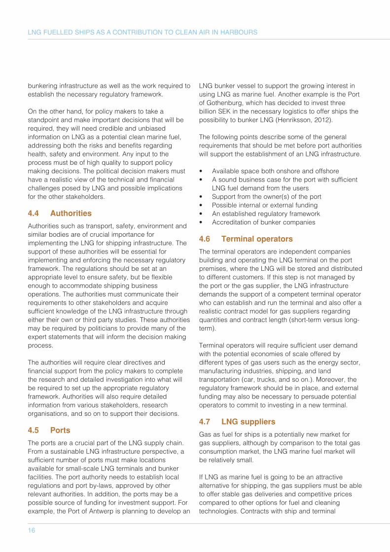
Figur 14: Liquiline semitrailer discharging to ferry
Photo: Liquiline
18
LNG FUELLED SHIPS AS A CONTRIBUTION TO CLEAN AIR IN HARBOURS
This chapter gives a brief overview of the presentregulations, standards and legislation regarding LNG.The initiatives that are currently being undertaken bygovernmental and private bodies are also discussed.Further information can be found in the Flemish Study.
5.1 Regulations for marine activities
The regulatory framework for seagoing vessels isoverseen by the International Maritime Organization(IMO). A brief overview of the most relevant parts ofthe framework is provided in the following sections.
5.1.1 Emission Control Area
Stricter emission controls than those required at aglobal level are enforced in specifically designatedgeographical areas. An Emission Control Area (ECA)can be designated for SOX, NOX or both. An ECA(NOX and SOX) comes in effect in 2012 in NorthAmerica, which includes most of the US and Canadiancoasts. The Baltic Sea, the North Sea and the EnglishChannel have been designated as an ECA for SOXemission reduction, also referred to as a SulphurEmission Control Area (SECA). This restriction meansthat the maximum allowable sulphur content of bunkerfuel is 1% (from July 1, 2010) and 0,1% from January1, 2015 (MOW, 2012).
5.1.2 SOLAS
The International Convention for the Safety of Life atSea (SOLAS) is an international maritime safety treaty.SOLAS requires member states to ensure that theirships comply with minimum safety standards withrespect to construction, equipment and operation.Chapter VII of this treaty requires the carriage of alldangerous goods to be in compliance with theInternational Maritime Dangerous Goods Code (IMDG)but it contains no specific reference to the use of LNG.The construction and equipment of ships carryingliquefied gasses in bulk and gas carriers is determinedin SOLAS to comply with the International Gas CarrierCode (IGC code) (MOW, 2012).
5.1.3 MARPOL
The International Convention for the Prevention ofPollution from Ships (MARPOL) is the maininternational convention covering prevention ofpollution by ships, from operational or accidentalcauses, of the marine environment. The Conventionincludes regulations aimed at preventing andminimizing pollution from ships and currently includessix technical Annexes. Annex VI covers the Preventionof Air Pollution from Ships and it establishes limits onsulphur oxide and nitrogen oxide emissions from shipexhausts, prohibiting deliberate emissions of ozone
5 Existing and future regulations, standards and legislations
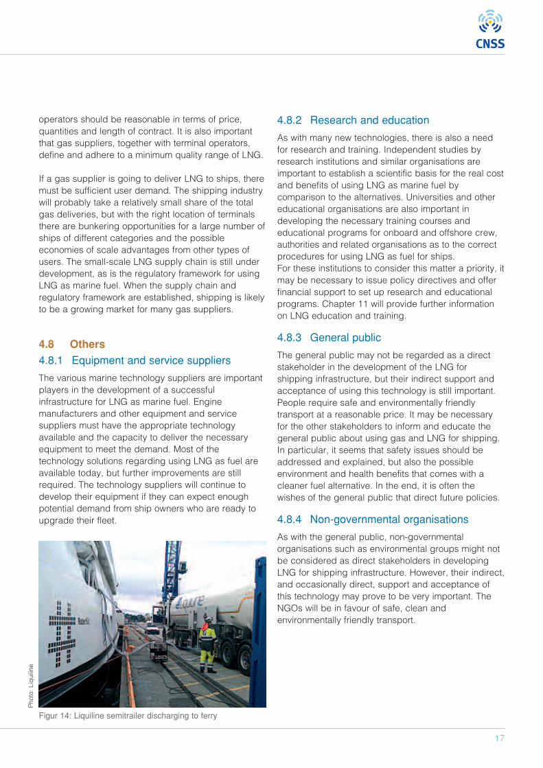
Figure 15: Viking Grace and MS Stavangerfjord
Photo: Viking Line
Photo: Fjordline
19
depleting substances. It also sets designated emissioncontrol areas with more stringent standards for SOx,NOx and particulate matter (ECAs) (IMO, 2013).
5.1.4 International Gas Carrier Code (IGCcode)
The IGC-code applies to gas carriers constructed onor after 1/7/1986. The code provides an internationalstandard for safe transportation by prescribing designand construction standards. Older carriers either haveto comply with the Code for the Construction andEquipment of Ships Carrying Liquefied Gases in Bulk(GC Code) or the Code for Existing Ships CarryingLiquefied Gases in Bulk (if the carrier was constructedbefore 31/12/1976) (MOW, 2012).
5.1.5 International Code for the Constructionof Gas Fuelled Ships (IGF code)
There are no formal IMO rules concerning LNG fueledvessels other than the IGC code that permits LNGcarriers to use their boil-off gas as a fuel. Thepublication of an international code for the constructionof gas fueled ships is expected to be published noearlier than 2013-14. As vessels are not permitted touse an oil fuel with a flashpoint of less than 60°(SOLAS, II-2, part B – prevention of fire and explosion),an interim guideline was published by the IMO,formally known as Resolution MSC.285(86). The IGFcode will not include the bunkering of LNG (MOW,2012).
5.1.6 Class rules
Seagoing vessels are all built according to class rulesset by a classification society. With the introduction ofthe first LNG carrier, the classification societiesdeveloped specific rules for the construction and safeoperation of LNG carriers. To ensure the safety andtechnical integrity of propulsion systems fueled byLNG, additional rules are being developed.
The International Association of Classification Societiesis a supra-structure that publishes the UnifiedRequirements, from which requirement M59 is ofparticular relevance: the Control and Safety Systemsfor Dual Fuel Diesel Engines (MOW, 2012).
5.1.7 European Maritime Safety Agency
The European Maritime Safety agency (EMSA) aims toprovide a consolidated version of possible commonEU-wide checklists, guidelines or standards for LNGbunkering. In May 2013 EMSA published a tender for astudy on standards and rules for bunkering of gas-fuelled ships. The first results are expected inDecember 2012. The tender contains 4 tasks (EMSA,2012):1. Provide a detailed description of the standards,
regulations and guidelines related to LNGbunkering
2. Provide a gap analysis on the requirements ofcurrent and on-going LNG related rules
3. Provide a consolidated version of a proposed forcommon EU-wide guidelines or standards for LNGbunkering
4. Present preliminary results of tasks 1-3 tostakeholders and member states
Two working groups have been created—a group ofEU pioneer ports and bunker operators and a group ofship and ferry operators. These groups will act asreference groups for study and potential new LNGrelated initiatives by EMSA.
5.2 Ship-to-shore and ship-to-shiptransfer standards
The regulatory framework for seagoing vessels doesnot include the transfer of materials. Advice andsupport for these operations are captured in currentoperating standards and best practices. These areprepared by societies such as the Society ofInternational Gas Tanker & Terminal Operators(SIGTTO) and the Oil Companies International MarineForum (OCIMF).
An important document for LNG is the Ship-to-ShipTransfer Guide (Liquefied Gases) by OCIMF/SIGTTO,which was originally written for the transfer of LPG atsea. Another important reference is the LNG ship-to-ship transfer guidelines. This covers the transfer ofLNG from carriers at anchor, alongside a shore jetty orunderway (MOW, 2012).
20
LNG FUELLED SHIPS AS A CONTRIBUTION TO CLEAN AIR IN HARBOURS
Several publications that cover ship-to-shore bunkeringare available, for example:
• Safety in Liquefied Gas Marine Transportation anTerminal operators
• Ship-Shore Interface–Safe Working Practices forLPG & Liquefied Chemical Gas Cargoes
• LNG operations in Port Areas, ESD arrangementsand Linker Ship-to-Shore Systems for LiquefiedGas Carriers
Another applicable OCIMF regulation is theInternational Safety Guide for Oil Tankers & Terminals(ISGOTT).
A procedural description on LNG ship-to ship-bunkering has been carried out by the Swedish MarineTechnology Forum1. The document's scope is LNGship-to-ship bunkering procedures in a portenvironment with concurrent cargo and passengerhandling in progress.
5.2.1 International organization forstandardization (ISO)
ISO produces International Standards, TechnicalReports, Technical Specifications, Publicly availableSpecifications, Technical Corrigenda and Guides. Twopublications, “ISO 28460:2010 – LNG ship to shoreinterface and Port Operations” and “ISO13709:2003 –Centrifugal pumps for Petroleum, Petrochemical andNatural Gas Industries” relate to the use of LNG. Aworking group (ISO TC67/WG10) is developingguidelines (in the form of a technical report) forsystems and installations that will use and supply ofLNG as fuel to ships. Results are expected in March2013 (MOW, 2012).
5.3 Global initiatives by involved parties
From a diverse group of companies and institutions,initiatives are currently underway to take the lead in theimplementation of LNG as marine fuel.
5.3.1 World Ports Climate Initiative
The International Association of Ports and Harbours(IAPH) organizes various international workgroups
within the World Ports Climate Initiative (WPCI, 2012),each focusing on a specific aspect of the environmentin the port sector. WPCI is supported by the EuropeanSea Ports Organization (ESPO) and EMSA. Themembers of these workgroups are mainly portauthorities. The WPCI LNG workgroup endeavors to bethe forum for the early standardisation processesbetween ports and to develop guidelines and/orassess the possible impact at ports with regard toinfrastructure, safety requirements for bunkering andthe legal aspects on the use of LNG. WPCI has coversfour main areas:
1. Bunker checklists and guidelines for theaccreditation of LNG bunkering companies
2. Give guidance to harmonize the approach of riskperimeters
3. Provide clear and unbiased information for thepublic
4. Create an information share point between ports
5.3.2 SIGTTO
SIGTTO is concerned that many people who maypotentially be involved in the LNG infrastructure, suchas bunkering suppliers and crew on LNG-fueledvessels, could lack relevant knowledge about theproperties and hazards of LNG. SIGTTO states that anincident on an LNG-fueled vessel will affect the widerLNG industry, which has an almost zero incident trackrecord at the present. Particular areas of concern aretraining of crew and bunker suppliers, simultaneousoperations and ship design. SIGTTO is involved withthe Ship-to-Ship Transfer Guide (Liquefied Gases). TheLNG Ship Fuel Safety Advisory Group promotes theuse of natural gas with an equivalent level of safety forthe large scale LNG transport industry. The AdvisoryGroup supports stakeholders in the marine gas fuelindustry, identifies issues and provides guidance andinformation based on the experience of groupmembers (MOW, 2012). At present, SIGTTO is:
• Participating in IMO work and correspondinggroups of the IGF code
• Part of the ISO TC67 working group 10• Reviewing of IGC Code
1Also: FKAB Marine Design, Linde Cryo AB, Det Norske Veritas AS (DNV), LNG GOT and White Smoke AB
21
5.3.3 North European LNG InfrastructureProject
In 2012, the EU founded a study on the feasibility foran LNG filling station infrastructure in North Europe2. Abrief overview of the permit processes andconsultation with authorities and the general public isprovided. An important part of this study containsrecommendations made on several aspects of theLNG, three of which focused on the permit process(MOW, 2012).
5.3.4 Methods for provision of LNG asshipping fuel in Flemish ports
The Flemish Department of Mobility and Public Work(MOW) commissioned a report on the methods for theproviding LNG as marine fuel in Flemish ports,subsequently referred to as the Flemish Study. Thisstudy also made some recommendations for thenecessary regulatory framework. Theserecommendations have been adopted by the recentlyfounded Flemish LNG expert group, chaired by MOW.
5.4 Regulations for onshore activities
5.4.1 International standards and bestpractices
5.4.1.1 European Committee forStandardization (CEN)
Most of the standards for land-based constructions inEurope are determined by the European Committee forStandardization. Some standards are voluntary, othersmay be mandatory under EU law. A list of standardsthat apply to LNG can be found in the Flemish Study(MOW, 2012).
5.4.1.2 The Code of Federal Regulations(CFR)
CFR standards are produced by different AmericanSocieties, such as the US Department ofTransportation Pipeline and Hazardous MaterialsSafety Administration and others. An overview of LNGapplicable regulations can be found in the FlemishStudy (MOW, 2012).
5.4.1.3 The National Fire ProtectionAssociation (NFPA)
The following NFPA standards apply to LNG facilities:
• NFPA 59A—Production and Storage of LNG • NFPA 30—Flammable and Combustible Liquids
Code
5.4.1.4 The American Petroleum Institute(API)
Most of the standards and recommended practicesfrom the API are dedicated to a single type ofequipment. The Flemish Study (MOW, 2012) providesan overview of the relevant documents.
5.4.2 European legislation
5.4.2.1 Provision of Public Consultation
The national regulations concerning the publicconsultation process and making information availableto the public are governed by the EnvironmentalImpact Assessment (EIA) Directive (85/337/EEC).According to this Directive each Member State candetermine if an Environmental Impact Assessment iscompulsory. The guidelines define minimumrequirements for public consultation. The provisions forpublic participation in the EIA Directive werestrengthened by the introduction of Directive2003/35/EC, which included early public consultationin the decision-making procedure (DMA, 2012).
5.4.2.2 The Seveso Directive
The Seveso Directive (96/82/EC) is the main piece ofEU legislation dealing specifically with the control ofonshore major accidents involving dangeroussubstances. The Directive implements two tiers ofcontrol:
• Lower tier (Seveso I)—Covers establishmentswhich hold more than 50 tonnes of LNG
• Upper tier (Seveso II)—Covers establishmentsabove 200 tonnes (DMA, 2012)
2 The main partner in the study was the Danish Maritime Authority, other partners were Bureau Veritas, Energigas Sverige,Fluxys LNG, Gasnor, Gazprom, GL, Gasunie, Gazprom, Lauritzen Kosan, MAN, Flemish department of Mobility and PublicWorks, Norwegian Ministry of Trade and Industry, Hirtshals Havn, Port of Rotterdam, Port Szczecin-swinoujscie, Port ofZeebrugge, Finnish Transport Safety agency, Den Danske Maritime Fond.

22
LNG FUELLED SHIPS AS A CONTRIBUTION TO CLEAN AIR IN HARBOURS
The Directive also obliges competent authorities to forexample, examine the Safety Report, to communicatewith the operator and the public, and to identify anypossible domino effects following a major incident.
5.4.2.3 International Carriage of DangerousGoods by Road (ADR)
The European agreement concerning the internationalcarriage of dangerous goods by road (ADR) has beenadopted by most of the 56 members of the UnitedNations Economic Commission for Europe (UNECE orECE) and incorporated into the various nationallegislations. The transportation of LNG is subject to theconditions outlined in Annexes A (construction andlabelling) and B (construction of the truck) (MOW,2012).
5.5 Regulations for transporting LNG viainland ship-based activities
The following section provides a brief overview of thetwo main governing bodies, the regulatory frameworkand standards governing the transportation of LNG viainland vessels.
5.5.1 The Rhine Vessel InspectionRegulations (RVIR)
The Central Commission for the Navigation on theRhine (CCNR) publishes its technical rules in the RVIR,which has become Europe's main technical referenceon the subject. The regulations have been partlytransposed into other national regulations by UNECEand the European Community (2006/87/EC). As aresult, the CCNR recognizes the validity of Communitycertificates on the Rhine, while Rhine certificates arealso been recognized on all EU waterways. Futuredevelopment of Rhine and EU regulations areexpected to evolve in tandem so as to remainidentical.
RVIR regulation is stringent but also flexible, with arange of implementation options including:
• Transitory provisions—Takes into account of thevested rights of older vessels
• Temporary 3-year provisions—CCNR may test anew rule for a period 3 years after which the rulewill be either abandoned or adopted
• Waivers—Vessel operators may use alternativetechnology not covered by the regulations other ifcomparable guarantees can be provided (MOW,2012)
5.5.2 The international carriage of dangerousgoods by inland waterways (ADN)
In 2000, the United Nations Economic Commission forEurope (UNECE) produced a European agreementconcerning the International Carriage of DangerousGoods by Inland Waterways (ADN). The regulationsoutlined in the annexes of the ADN contain provisionsconcerning the carriage of dangerous substancesincluding the requirements and procedures forinspections, issuing certificates of approval,recognition of classification societies, monitoring,training and the examination of experts.
Inland shipping legislation—ADN, RVIR and EuropeanDirective—contain specific information about the use offuel in a shipping engine. As the legislation states thatthe use of fuel with a flashpoint below 55°C is notpermitted, propulsion by LNG is prohibited in inlandwaterways. The transportation of LNG as cargo is alsoprohibited. ADN legislation only applies to inland shipsthat are certified for the transportation of dangerousgoods by inland waterways. Ferries and other shipsthat do not transport dangerous goods do not have tocomply with ADN legislation. Despite the fact that thecurrent European legislation prohibits the use of LNGas a fuel, there are already inland ships inside theEuropean Union that are using LNG as marine fuel. Toallow LNG-fuelled ships on national waters, the Dutchauthorities introduced a temporary exemption throughUNECE / CCNR, which implies that the vesselobtaining the exemption can operate in all EUcountries. This temporary exemption is possiblebecause of the waiver arrangements available in theRVIR that provides ship owners and builders theopportunity to implement alternate, equivalentarrangements. Any proposed exemptions mustdemonstrate that the alternative arrangement is at leastas safe as the original arrangements governed by theRVIR. One disadvantage of the waiver principle is twosister ships cannot use the same waiver as they arenot considered unique (MOW, 2012).
23
5.5.3 International Safety Guide for InlandTank-barges and Terminals (ISGINTT)
The OCIMF, together with other stakeholders for inlandwaterways (such as the CCNR), developed theInternational Safety Guide for Inland Tank-barges andTerminals (ISGINTT). The ISGINTT is not intended toreplace or amend current legislation as ADN and RVIR,but to provide additional recommendations. The CCNRsupports the ISGINTT as the principal industryreference manual for the safe operation of tankers andthe terminals that serve them (MOW, 2012).
5.6 Conclusion
As the permitted sulphur emissions inside an ECA willbe further restricted by 2015, an enormous amount ofinfrastructure redevelopment and associated activities
will be required to facilitate the use of LNG as marinefuel. The main parties involved in the shipping industryare urging the adaption of existing legislation andstandards to support the required changes. A majorconsideration is the desire to maintain the good safetyrecord that LNG has acquired over the years. Althoughthis much needed, safety-focused development isvulnerable on two fronts. First-adopter organisationscould be hampered if legislative bodies are notsufficiently involved with currently developing projects.Conversely, too many single-party initiatives could leadto a proliferation of rules and standards that may notbe in line with the eventual legislation. Open andconstructive communication between all stakeholdersis viewed as crucial to avoiding both of these potentialoutcomes.
Photo: Shell
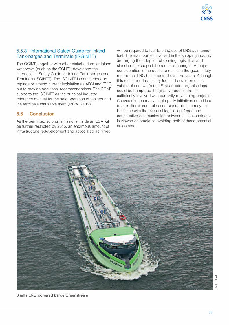
Shell’s LNG powered barge Greenstream
6.1 Present status
As described in Chapter 5 there are no currentinternational standards or guidelines for bunkeringLNG as fuel. A number of LNG transfer guidelines areavailable, for example from the SIGTTO, but theseguidelines are limited to LNG cargo transfer and arenot applicable for bunkering LNG due to the followingtransfer arrangements:
• LNG transfer takes place in dedicated separatedareas such as special harbours for tanker
• Trained crews and personnel handle the LNG• No simultaneous cargo handling operation• No requirement to consider the effect on third
parties such as passengers
Additionally the existing transfer guidelines are limitedto the ship-to-ship transfer of LNG and do not take intoaccount the range of possible bunkering processesincluding:
• Shore-to-ship• Truck-to-ship• Connection and disconnection of mobile fuel tanks
6.2 On-going international developments
The most important international developments withrespect to LNG rules at present are the developmentof the IGF Code by the IMO sub-committee BLG andthe development of Guidelines for bunkering LNG bythe ISO Technical Committee 67 Working Group 10. Asthe IGF code will only include requirements for thebunker station, all other aspects related to the LNGbunkering process were addressed by the ISO TC 67WG 10, which was established to develop the"Guidelines for systems and installations for supply ofLNG as fuel to Ships". The working group will producethe final set of guidelines by 2014, with a high-leveldraft version of the guidelines available during the firsthalf of 2013.
The objectives of the ISO guidelines are to standardizethe interface between ship and bunkering facilities,
connection and disconnection, the emergencyshutdown procedures and the LNG bunkering processcontrol, to ensure that an LNG-fuelled ship can refuelsafely and reliably regardless of the type of bunkeringfacility. The LNG bunkering interface comprises thearea of LNG transfer and includes manifold, valves,safety and security systems, and the personnelinvolved in the LNG bunkering operations.
The structure of the ISO guidelines is as follows:1. Scope2. Normative references3. Terms and definitions4. General principles5. Properties and behaviour of LNG as fuel6. Safety7. Functional requirements for LNG bunkering
system8. Requirements to components and systems9. Training10. Requirements for documentation
6.3 National initiatives and solutions
In addition to the on-going international developmentof rules within different European countries, bunkeringprocedures have been developed and are allowedsubject to special permission:
• Many of the existing LNG-fuelled vessels currentlyoperate in Norwegian waters. They are bunkeredvia truck or local bunkering stations. Under normalconditions general permission is given in the lawand is based on risk analysis. Under specialconditions permission is given from NorwegianDirectorate for Civil Protection and the local firebrigade.
• During the LESAS project the current framework ofregulation, codes and standards for theestablishment of a small scale LNG supply chain,and using LNG as fuel for shipping and vehicles inthe Netherlands has been investigated for variousbunkering operations.
24
LNG FUELLED SHIPS AS A CONTRIBUTION TO CLEAN AIR IN HARBOURS
6 Bunkering procedures
25
• Germanischer Lloyd (GL) undertook a study onbehalf of the Federal Ministry of Transport,Building and Urban development ( ”Feasibilitystudy for bunkering liquefied gas within Germanports”) to investigate the current regulatoryframework and safety requirements for a safebunkering of LNG within German ports. One of theresults of the study is a draft report on safetyoperations for LNG bunkering within ports.
• In March 2013 the European Maritime SafetyAgency (EMSA) published the “study onstandards and rules for bunkering of gas-fuelledships” carried out by GL. The objective of theinvestigation is to provide an overview of theexisting rule framework, the current developmentof rules regarding bunkering gas-fuelled vessels,and to identify a possible requirement for aEuropean edict for regulating LNG bunkering.
6.4 Conclusion
At present the development of the ISO TC 67 WG10PT1 LNG bunkering guidelines seems to be the mostimportant step towards the international regulation ofbunkering LNG as fuel for shipping, taking intoaccount a common risk assessment approach as wellas functional and safety requirements for the transfersystem. A first draft of the guidelines will be availablein March 2013. It remains to be seen if theseguidelines will provide the necessary guidance toensure safe LNG bunkering within normal port limitsand during normal harbour operation of vesselsincluding:
• At each harbour within the port• During cargo loading and unloading• During passenger embarkation and
disembarkation
26
LNG FUELLED SHIPS AS A CONTRIBUTION TO CLEAN AIR IN HARBOURS
7.1 Introduction
To ensure safe bunkering for LNG, the external risksfor the bunkering operation itself and anyenvironmental risks which might result from thebunkering process should be evaluated. To identifypossible risks, an evaluation of an LNG-Vesseloperating in the Port of Hamburg has been carried outduring the project. The basis for the risk evaluation ofan LNG infrastructure described below forms aHAZID—to identify worst case scenarios and anavigational safety study for the detailed riskassessment. The aim of this showcase evaluation is toreport findings, exchange experiences and discussways to encourage stakeholders, such as ports,terminal operators or shipping companies, to considerswitching to LNG and create a new market.
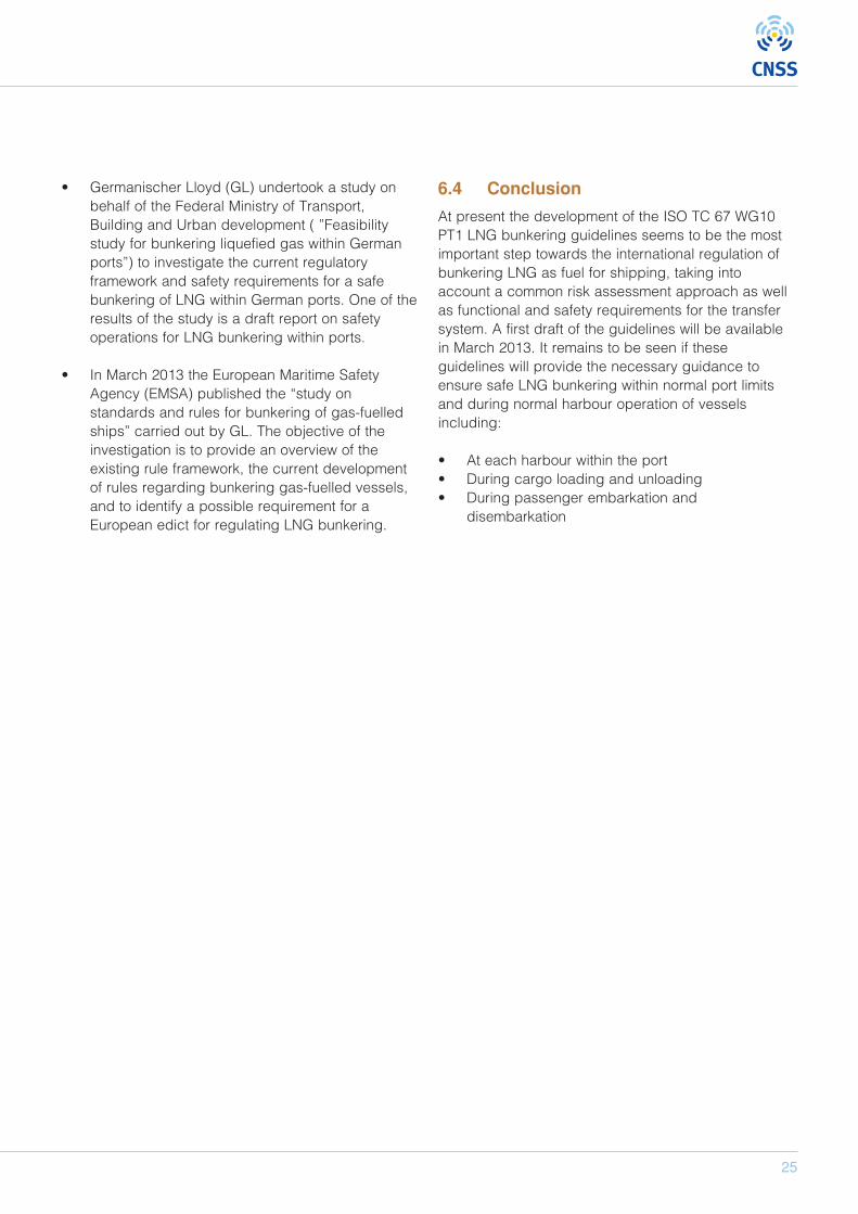
As there is no LNG infrastructure in the Port ofHamburg at present, LNG must be delivered to theport. The most likely supply chain for the Port ofHamburg is shown in Figure 16. Firstly, LNG will betransported to Hamburg from a large LNGImport/Export terminal in Europe (for example,Zeebrügge) or from a small scale LNG productionplant in Northern Europe via an LNG Feeder vessel.Because the distance to an LNG source is longer thanconsidered practical, it was assumed that an
intermediate LNG terminal will be constructed inHamburg to store and redistribute LNG in the harbour.This intermediate terminal will be the basis for the LNGbunker vessel, which distributes the LNG to therespective receiving vessels. Given normal operatingprocedures for such vessels, it is assumed that abunker vessel will normally only transport the fuelordered by one customer (delivery on demand).
7.2 HAZID
For the purposes of hazard identification (HAZID),bunkering from an LNG bunker vessel to a receivingcontainer feeder vessel was studied to identify themain risks associated with LNG bunkering operationsin the harbour of Hamburg. An LNG bunker vesseldesign from TGE, developed as part of the BunGas-project, and a GL LNG container feeder vessel werechosen for the investigation.
The bunker vessel is designed to handle and transportLNG and marine gas oil (MGO) and can also deliverLNG and marine gasoil simultaneously to a receivingvessel. The bunker vessel is equipped with a specialtransfer arm, comparable to a hard arm solution,carrying the piping and all relevant systems for thetransfer of LNG and MGO. The transfer arm has anoperating distance of 20 m and is supported within theship structure between the LNG storage tanks.
7 Bunkering and navigational safety evaluation
LNG Feedervessel
Intermediateterminal
Bunker vesselTGE
Receiving vesselGL Feeder
Figure 16: LNG supply chain for the example Port of Hamburg
Photo: G
ermanischer Lloyds/CNSS
27
Movements of both ships during fuel transfer can becontrolled by an automatic adjustment control systemthat equalizes all relative movements.
The principle dimensions of the TGE bunker vessel areas follows:
Length overall 98.60 mLength b.p. 93.00 mBreath moulded 14.20 mDepth moulded 7.60 mDraught (design) 4.20 mDeadweight 2050 tCargo tank volume LNG (100%) 3000 m3
Cargo tank volume MGO (100%) 400 m3
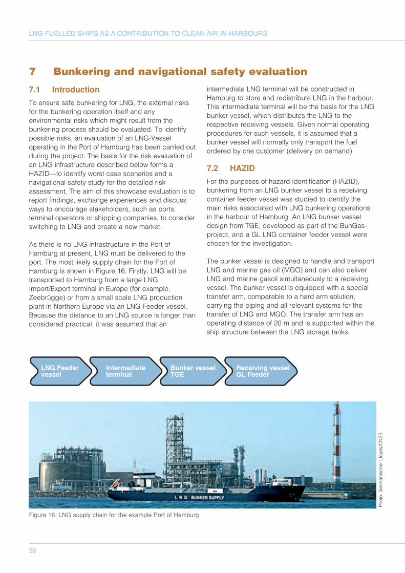
The bunker vessel will bunker an LNG-fuelledcontainer feeder. For the purposes of this study thedesign of the GL LNG container feeder was used (seeFigure 18).
The principle dimensions of the container feeder are asfollows:
Length overall 166.15 mLength b.p. 155.08 mBreath moulded 25.00 mDepth moulded 14.20 mDraught (design) 9.50 mDeadweight 18300 tCapacity 1240 TEUBunker tank volume LNG (100%) 670 m3
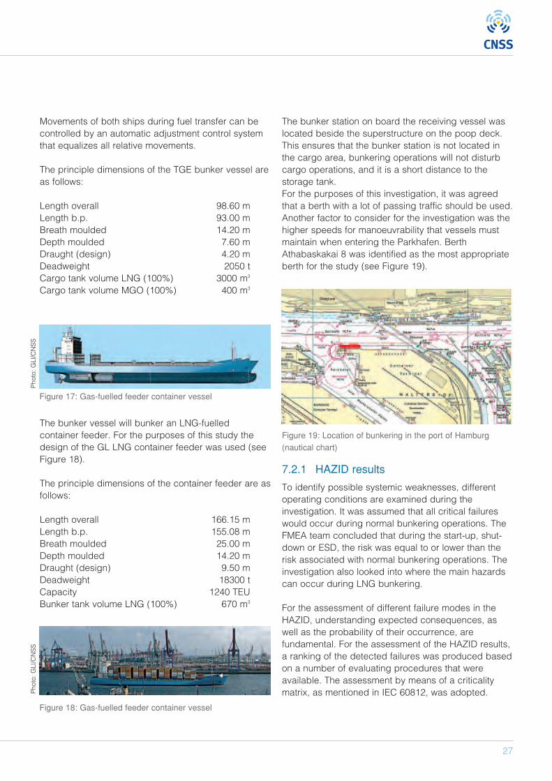
The bunker station on board the receiving vessel waslocated beside the superstructure on the poop deck.This ensures that the bunker station is not located inthe cargo area, bunkering operations will not disturbcargo operations, and it is a short distance to thestorage tank.For the purposes of this investigation, it was agreedthat a berth with a lot of passing traffic should be used.Another factor to consider for the investigation was thehigher speeds for manoeuvrability that vessels mustmaintain when entering the Parkhafen. BerthAthabaskakai 8 was identified as the most appropriateberth for the study (see Figure 19).
Figure 19: Location of bunkering in the port of Hamburg(nautical chart)
7.2.1 HAZID results
To identify possible systemic weaknesses, differentoperating conditions are examined during theinvestigation. It was assumed that all critical failureswould occur during normal bunkering operations. TheFMEA team concluded that during the start-up, shut-down or ESD, the risk was equal to or lower than therisk associated with normal bunkering operations. Theinvestigation also looked into where the main hazardscan occur during LNG bunkering.
For the assessment of different failure modes in theHAZID, understanding expected consequences, aswell as the probability of their occurrence, arefundamental. For the assessment of the HAZID results,a ranking of the detected failures was produced basedon a number of evaluating procedures that wereavailable. The assessment by means of a criticalitymatrix, as mentioned in IEC 60812, was adopted.
Figure 17: Gas-fuelled feeder container vessel
Figure 18: Gas-fuelled feeder container vessel
Photo: G
Ll/CNSS
Photo: G
Ll/CNSS
28
LNG FUELLED SHIPS AS A CONTRIBUTION TO CLEAN AIR IN HARBOURS
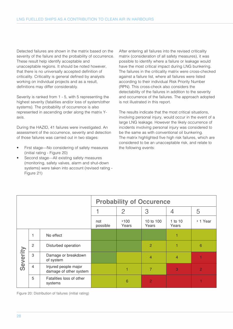
Detected failures are shown in the matrix based on theseverity of the failure and the probability of occurrence.These result help identify acceptable andunacceptable regions. It should be noted however,that there is no universally accepted definition ofcriticality. Criticality is general defined by analystsworking on individual projects and as a result,definitions may differ considerably.
Severity is ranked from 1 - 5, with 5 representing thehighest severity (fatalities and/or loss of system/othersystems). The probability of occurrence is alsorepresented in ascending order along the matrix Y-axis.
During the HAZID, 41 failures were investigated. Anassessment of the occurrence, severity and detectionof those failures was carried out in two stages:
• First stage—No considering of safety measures(initial rating - Figure 20)
• Second stage—All existing safety measures(monitoring, safety valves, alarm and shut-downsystems) were taken into account (revised rating -Figure 21)
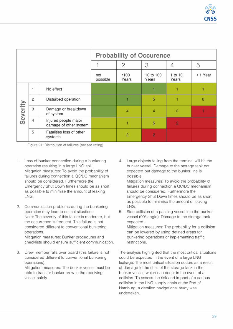
After entering all failures into the revised criticalitymatrix (consideration of all safety measures), it waspossible to identify where a failure or leakage wouldhave the most critical impact during LNG bunkering.The failures in the criticality matrix were cross-checkedagainst a failure list, where all failures were listedaccording to their individual Risk Priority Number(RPN). This cross-check also considers thedetectability of the failures in addition to the severityand occurrence of the failures. The approach adoptedis not illustrated in this report.
The results indicate that the most critical situations,involving personal injury, would occur in the event of alarge LNG leakage. However the likely occurrence ofincidents involving personal injury was considered tobe the same as with conventional oil bunkering.The matrix highlighted five high risk failures, which areconsidered to be an unacceptable risk, and relate tothe following events:
Figure 20: Distribution of failures (initial rating)
Probability of Occurence
1 2 3 4 5not ›100 10 to 100 1 to 10 ‹ 1 Yearpossible Years Years Years
1 No effect 1
2 Disturbed operation 2 1 6
3 Damage or breakdown 4 4 1of system
4 Injured people majordamage of other system 1 7 3 2
5 Fatalities loss of other systems 6 2 1
Severity
29
1. Loss of bunker connection during a bunkeringoperation resulting in a large LNG spill.Mitigation measures: To avoid the probability offailures during connection a QC/DC mechanismshould be considered. Furthermore theEmergency Shut Down times should be as shortas possible to minimise the amount of leakingLNG.
2. Communication problems during the bunkeringoperation may lead to critical situations. Note: The severity of this failure is moderate, butthe occurrence is frequent. This failure is notconsidered different to conventional bunkeringoperations.Mitigation measures: Bunker procedures andchecklists should ensure sufficient communication.
3. Crew member falls over board (this failure is notconsidered different to conventional bunkeringoperations).Mitigation measures: The bunker vessel must beable to transfer bunker crew to the receivingvessel safely.
4. Large objects falling from the terminal will hit thebunker vessel. Damage to the storage tank notexpected but damage to the bunker line ispossible.Mitigation measures: To avoid the probability offailures during connection a QC/DC mechanismshould be considered. Furthermore theEmergency Shut Down times should be as shortas possible to minimise the amount of leakingLNG.
5. Side collision of a passing vessel into the bunkervessel (90° angle). Damage to the storage tankexpected. Mitigation measures: The probability for a collisioncan be lowered by using defined areas forbunkering operations or implementing trafficrestrictions.
The analysis highlighted that the most critical situationscould be expected in the event of a large LNGleakage. The most critical situation occurs as a resultof damage to the shell of the storage tank in thebunker vessel, which can occur in the event of acollision. To assess the risk and impact of a seriouscollision in the LNG supply chain at the Port ofHamburg, a detailed navigational study wasundertaken.
Figure 21: Distribution of failures (revised rating)
Probability of Occurence
1 2 3 4 5not ›100 10 to 100 1 to 10 ‹ 1 Yearpossible Years Years Years
1 No effect 1 1 1
2 Disturbed operation 1 5 1 8
3 Damage or breakdown 4 4 2 1of system
4 Injured people majordamage of other system 1 5 2
5 Fatalities loss of other systems 2 2
Severity
30
LNG FUELLED SHIPS AS A CONTRIBUTION TO CLEAN AIR IN HARBOURS
7.3 Traffic analysis
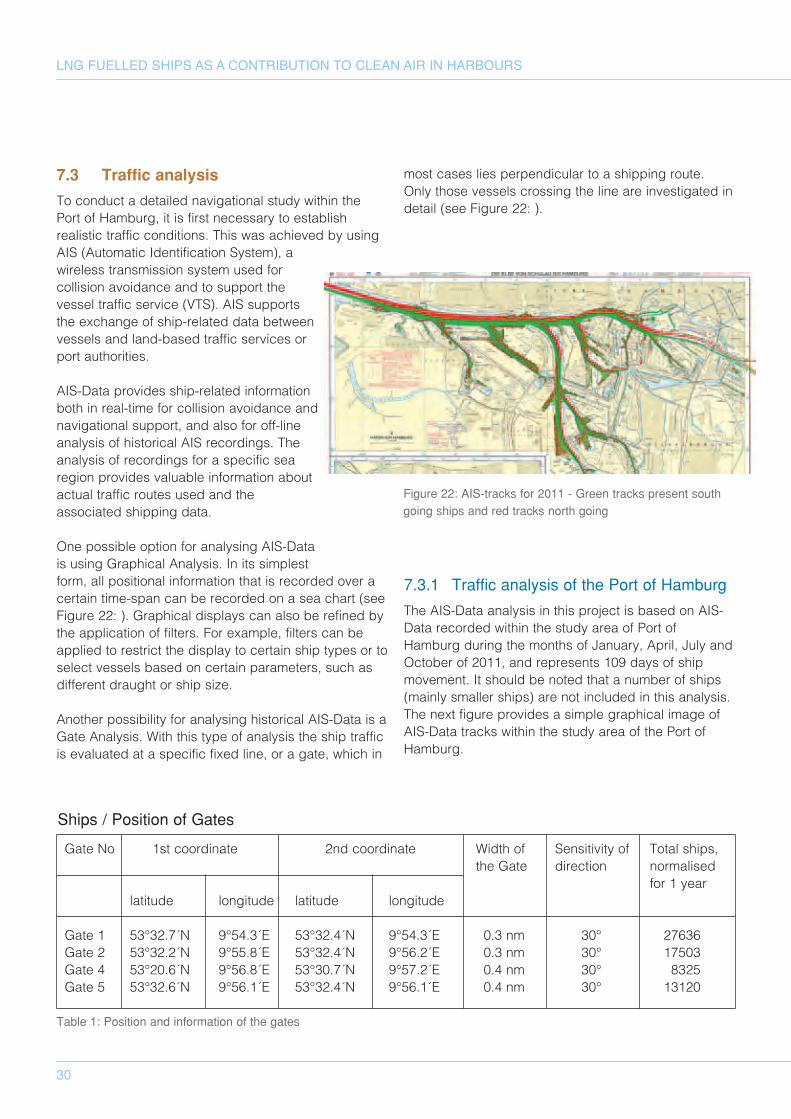
To conduct a detailed navigational study within thePort of Hamburg, it is first necessary to establishrealistic traffic conditions. This was achieved by usingAIS (Automatic Identification System), awireless transmission system used forcollision avoidance and to support thevessel traffic service (VTS). AIS supportsthe exchange of ship-related data betweenvessels and land-based traffic services orport authorities.
AIS-Data provides ship-related informationboth in real-time for collision avoidance andnavigational support, and also for off-lineanalysis of historical AIS recordings. Theanalysis of recordings for a specific searegion provides valuable information aboutactual traffic routes used and theassociated shipping data.
One possible option for analysing AIS-Datais using Graphical Analysis. In its simplestform, all positional information that is recorded over acertain time-span can be recorded on a sea chart (seeFigure 22: ). Graphical displays can also be refined bythe application of filters. For example, filters can beapplied to restrict the display to certain ship types or toselect vessels based on certain parameters, such asdifferent draught or ship size.
Another possibility for analysing historical AIS-Data is aGate Analysis. With this type of analysis the ship trafficis evaluated at a specific fixed line, or a gate, which in
most cases lies perpendicular to a shipping route.Only those vessels crossing the line are investigated indetail (see Figure 22: ).
7.3.1 Traffic analysis of the Port of Hamburg
The AIS-Data analysis in this project is based on AIS-Data recorded within the study area of Port ofHamburg during the months of January, April, July andOctober of 2011, and represents 109 days of shipmovement. It should be noted that a number of ships(mainly smaller ships) are not included in this analysis.The next figure provides a simple graphical image ofAIS-Data tracks within the study area of the Port ofHamburg.
Figure 22: AIS-tracks for 2011 - Green tracks present southgoing ships and red tracks north going
Gate No 1st coordinate 2nd coordinate Width of Sensitivity of Total ships,the Gate direction normalised
for 1 yearlatitude longitude latitude longitude
Gate 1 53°32.7´N 9°54.3´E 53°32.4´N 9°54.3´E 0.3 nm 30° 27636Gate 2 53°32.2´N 9°55.8´E 53°32.4´N 9°56.2´E 0.3 nm 30° 17503Gate 4 53°20.6´N 9°56.8´E 53°30.7´N 9°57.2´E 0.4 nm 30° 8325Gate 5 53°32.6´N 9°56.1´E 53°32.4´N 9°56.1´E 0.4 nm 30° 13120
Table 1: Position and information of the gates
Ships / Position of Gates
31
Gate analyses have been performed at five locations inthe Port of Hamburg. Gate 1 is close to the jetty ofAthabaskakai. Gate 2 detects the passing traffic fromand to Köhlbrand. Gate 3 detects the shipping trafficgoing in and out of the Waltershofer Hafen (results atGate 3 have not been considered within this analysis),Gate 4 detects the traffic passing the Rethe from andto the Kattwykhafen, and Gate 5 detects the trafficpassing the Ferry Terminal Altona. These data areused as input parameters for the quantitative riskassessment.
7.4 Quantitative risk assessment
The applied model for calculating the frequency ofcollision accidents in the Port of Hamburg involves theuse of a so-called causation probability that ismultiplied by a theoretically obtained number ofcollision candidates.
The causation factor models the probability that theofficer on the watch has not reacted in time given thathis vessel is on a collision course with another vessel.The numerical value of the causation probability is nota single value but often varies in different geographicallocations.
Due to a causation factor (probability that last-minuterecovery action will be unsuccessful) of 2.7 (Karlssonet al, 1998), a value of 10-5 seems to be adequate andis used for the following calculations of head-oncollisions.
7.4.1 Considered situations for the LNG-Tanker
The following two scenarios have been evaluated foran LNG-Tanker (LNG-T) operating within the Port ofHamburg:
• Collision on transit within the Port of Hamburg:
• For an LNG-Tanker the head-on collision isanalysed for its route within Port of Hamburg.For the analysis the speed of the LNG-Tankeron its transit within Port of Hamburg was setto 8 kn, the average ship speed in this area.
• Overtaking collisions, collisions at junctionsas well as grounding are indirectlyconsidered due to calibration with actualCollision Rates of the Port of Hamburg.
• Collision at berthing position:
• The probability of being involved in a collisionwhile off-loading at Kattwykhafen has alsobeen analysed. The probable berth atKattwykhafen provides some protectionagainst such collisions, and this has beentaken into consideration by reducing thevulnerable length to half the ship length.
7.4.2 Considered situations for the LNG-Bunker Vessel
The following scenarios for an LNG-Bunker Vessel(LNG-BSV) operating within the Port of Hamburg havebeen evaluated:• Collision on transit within the Port of Hamburg.
• For the LNG-Bunker Vessel a head-oncollision along its route within the Port ofHamburg has been analysed. For theanalysis the speed of the LNG-Bunker Vesselon its transit within Port of Hamburg was setto 8 kn, the average ship speed in this area.
• Overtaking collisions, collisions at Junctionsas well as grounding are indirectlyconsidered due to calibration with actualCollision Rates of the Port of Hamburg.
• The possibility that the LNG-Bunker Vesselhas been hit while on service at a bunkeringground, alongside a jetty or by other vesselhas been analysed for Athabaskakai andFerry Terminal Altona (striking events).
• Collision at Kattwykhafen whileWaiting/Loading.
7.4.3 Head-on collisions in a shipping Lane
For head-on collisions, the probability can becalculated by using the meeting and causationprobabilities for collisions. For head-on collisions, themeeting probability M can be estimated by thefollowing formula given by Karlsson et al (1998). Theresults are provided in section 7.5 for a singleentry/exit operation within the Port of Hamburg.
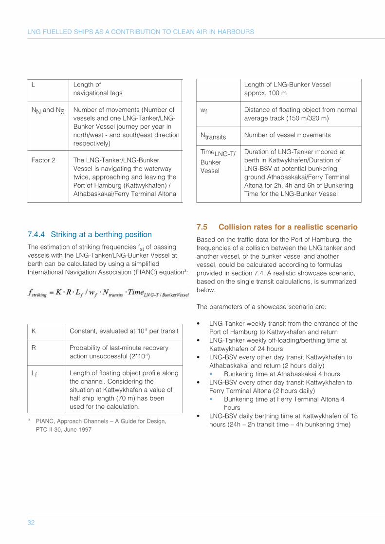
32
LNG FUELLED SHIPS AS A CONTRIBUTION TO CLEAN AIR IN HARBOURS
L Length of navigational legs
NN and NS Number of movements (Number ofvessels and one LNG-Tanker/LNG-Bunker Vessel journey per year innorth/west - and south/east directionrespectively)
Factor 2 The LNG-Tanker/LNG-BunkerVessel is navigating the waterwaytwice, approaching and leaving thePort of Hamburg (Kattwykhafen) /Athabaskakai/Ferry Terminal Altona
7.4.4 Striking at a berthing position
The estimation of striking frequencies fst of passingvessels with the LNG-Tanker/LNG-Bunker Vessel atberth can be calculated by using a simplifiedInternational Navigation Association (PIANC) equation3:
K Constant, evaluated at 10-5 per transit
R Probability of last-minute recoveryaction unsuccessful (2*10-4)
Lf Length of floating object profile alongthe channel. Considering thesituation at Kattwykhafen a value ofhalf ship length (70 m) has beenused for the calculation.
Length of LNG-Bunker Vessel approx. 100 m
wf Distance of floating object from normalaverage track (150 m/320 m)
Ntransits Number of vessel movements
TimeLNG-T/ Duration of LNG-Tanker moored at
Bunker berth in Kattwykhafen/Duration of
Vessel LNG-BSV at potential bunkering ground Athabaskakai/Ferry TerminalAltona for 2h, 4h and 6h of BunkeringTime for the LNG-Bunker Vessel
7.5 Collision rates for a realistic scenario
Based on the traffic data for the Port of Hamburg, thefrequencies of a collision between the LNG tanker andanother vessel, or the bunker vessel and anothervessel, could be calculated according to formulasprovided in section 7.4. A realistic showcase scenario,based on the single transit calculations, is summarizedbelow.
The parameters of a showcase scenario are:
• LNG-Tanker weekly transit from the entrance of thePort of Hamburg to Kattwykhafen and return
• LNG-Tanker weekly off-loading/berthing time atKattwykhafen of 24 hours
• LNG-BSV every other day transit Kattwykhafen toAthabaskakai and return (2 hours daily)• Bunkering time at Athabaskakai 4 hours
• LNG-BSV every other day transit Kattwykhafen toFerry Terminal Altona (2 hours daily)• Bunkering time at Ferry Terminal Altona 4
hours• LNG-BSV daily berthing time at Kattwykhafen of 18
hours (24h – 2h transit time – 4h bunkering time)3 PIANC, Approach Channels – A Guide for Design, PTC II-30, June 1997
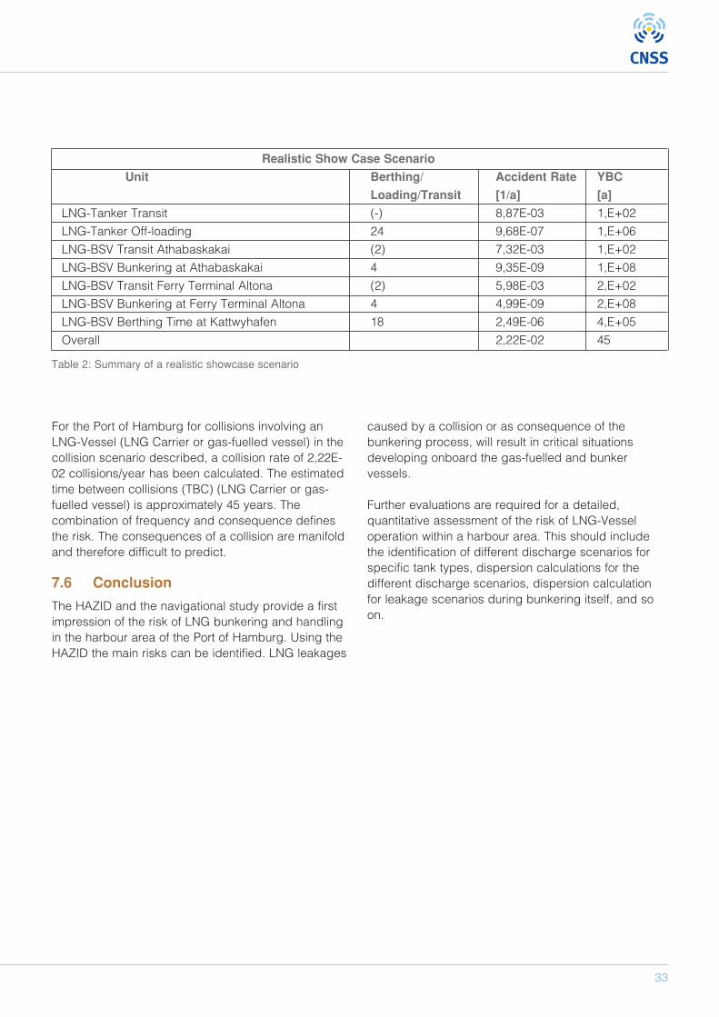
33
For the Port of Hamburg for collisions involving anLNG-Vessel (LNG Carrier or gas-fuelled vessel) in thecollision scenario described, a collision rate of 2,22E-02 collisions/year has been calculated. The estimatedtime between collisions (TBC) (LNG Carrier or gas-fuelled vessel) is approximately 45 years. Thecombination of frequency and consequence definesthe risk. The consequences of a collision are manifoldand therefore difficult to predict.
7.6 Conclusion
The HAZID and the navigational study provide a firstimpression of the risk of LNG bunkering and handlingin the harbour area of the Port of Hamburg. Using theHAZID the main risks can be identified. LNG leakages
caused by a collision or as consequence of thebunkering process, will result in critical situationsdeveloping onboard the gas-fuelled and bunkervessels.
Further evaluations are required for a detailed,quantitative assessment of the risk of LNG-Vesseloperation within a harbour area. This should includethe identification of different discharge scenarios forspecific tank types, dispersion calculations for thedifferent discharge scenarios, dispersion calculationfor leakage scenarios during bunkering itself, and soon.
Table 2: Summary of a realistic showcase scenario
Realistic Show Case Scenario
Unit Berthing/ Accident Rate YBC
Loading/Transit [1/a] [a]
LNG-Tanker Transit (-) 8,87E-03 1,E+02
LNG-Tanker Off-loading 24 9,68E-07 1,E+06
LNG-BSV Transit Athabaskakai (2) 7,32E-03 1,E+02
LNG-BSV Bunkering at Athabaskakai 4 9,35E-09 1,E+08
LNG-BSV Transit Ferry Terminal Altona (2) 5,98E-03 2,E+02
LNG-BSV Bunkering at Ferry Terminal Altona 4 4,99E-09 2,E+08
LNG-BSV Berthing Time at Kattwyhafen 18 2,49E-06 4,E+05
Overall 2,22E-02 45
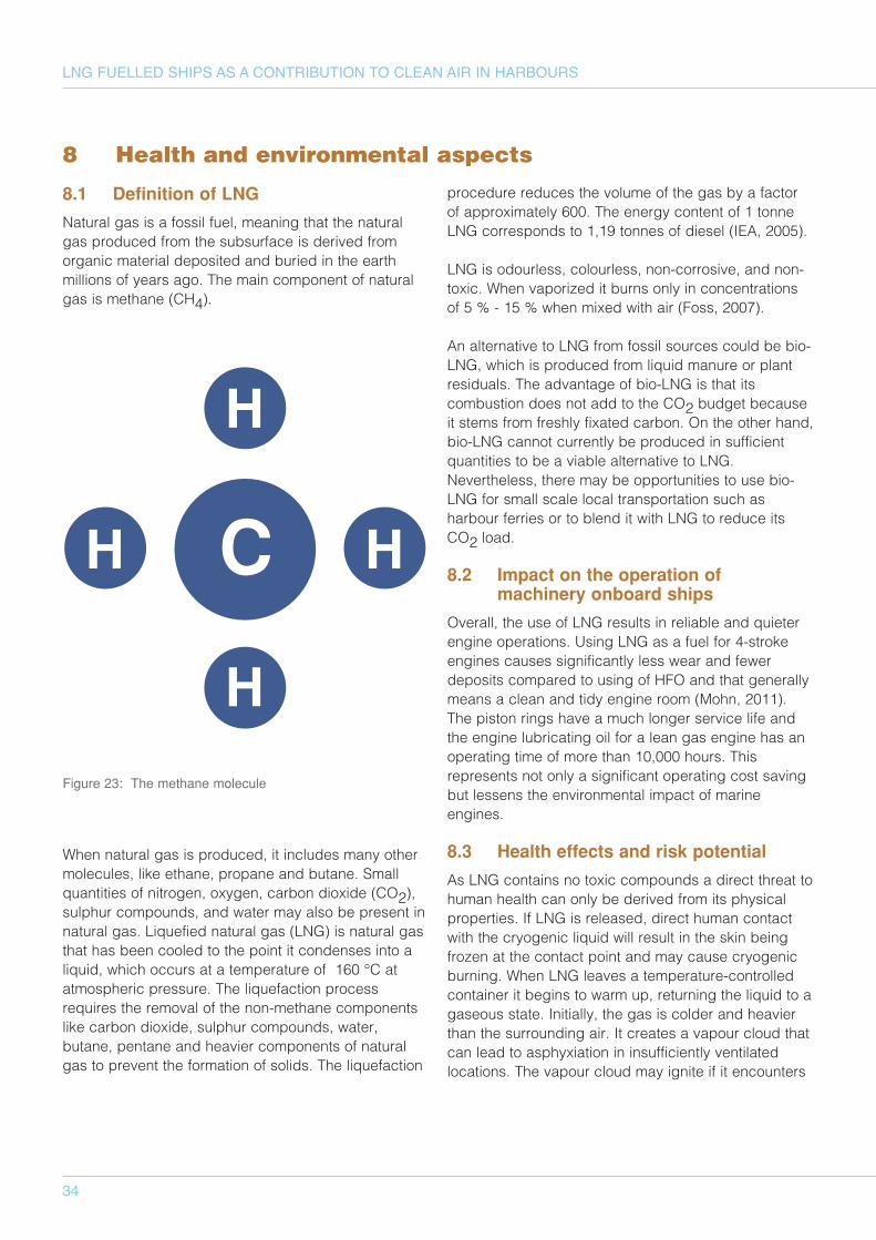
34
LNG FUELLED SHIPS AS A CONTRIBUTION TO CLEAN AIR IN HARBOURS
8.1 Definition of LNG
Natural gas is a fossil fuel, meaning that the naturalgas produced from the subsurface is derived fromorganic material deposited and buried in the earthmillions of years ago. The main component of naturalgas is methane (CH4).
When natural gas is produced, it includes many othermolecules, like ethane, propane and butane. Smallquantities of nitrogen, oxygen, carbon dioxide (CO2),sulphur compounds, and water may also be present innatural gas. Liquefied natural gas (LNG) is natural gasthat has been cooled to the point it condenses into aliquid, which occurs at a temperature of 160 °C atatmospheric pressure. The liquefaction processrequires the removal of the non-methane componentslike carbon dioxide, sulphur compounds, water,butane, pentane and heavier components of naturalgas to prevent the formation of solids. The liquefaction
procedure reduces the volume of the gas by a factorof approximately 600. The energy content of 1 tonneLNG corresponds to 1,19 tonnes of diesel (IEA, 2005).
LNG is odourless, colourless, non-corrosive, and non-toxic. When vaporized it burns only in concentrationsof 5 % - 15 % when mixed with air (Foss, 2007).
An alternative to LNG from fossil sources could be bio-LNG, which is produced from liquid manure or plantresiduals. The advantage of bio-LNG is that itscombustion does not add to the CO2 budget becauseit stems from freshly fixated carbon. On the other hand,bio-LNG cannot currently be produced in sufficientquantities to be a viable alternative to LNG.Nevertheless, there may be opportunities to use bio-LNG for small scale local transportation such asharbour ferries or to blend it with LNG to reduce itsCO2 load.
8.2 Impact on the operation ofmachinery onboard ships
Overall, the use of LNG results in reliable and quieterengine operations. Using LNG as a fuel for 4-strokeengines causes significantly less wear and fewerdeposits compared to using of HFO and that generallymeans a clean and tidy engine room (Mohn, 2011).The piston rings have a much longer service life andthe engine lubricating oil for a lean gas engine has anoperating time of more than 10,000 hours. Thisrepresents not only a significant operating cost savingbut lessens the environmental impact of marineengines.
8.3 Health effects and risk potential
As LNG contains no toxic compounds a direct threat tohuman health can only be derived from its physicalproperties. If LNG is released, direct human contactwith the cryogenic liquid will result in the skin beingfrozen at the contact point and may cause cryogenicburning. When LNG leaves a temperature-controlledcontainer it begins to warm up, returning the liquid to agaseous state. Initially, the gas is colder and heavierthan the surrounding air. It creates a vapour cloud thatcan lead to asphyxiation in insufficiently ventilatedlocations. The vapour cloud may ignite if it encounters
8 Health and environmental aspects
Support for LNG for shippingUse of LNG for shipping
Implementation requires Stakeholder Decision requires
Investments in LNG fuellednewbuildings/conversions.
Willingness to take a risk ofpossibly choosing the wronghorse/technology because of theuncertainty of future costs ofusing LNG compared to fuel oilsand other alternatives.
Sufficiently trained crew
A sound business case
Clarity on the methane slip ofcetrian engines, assurance thatLNG is a viable option in termsof CO2 emissions (especiallytaking a possible future ETSsystem into account)
Ship owners/operators Price and availability of LNG asship fuel must be competitive(preferably with HFO) andreliable.
Regulatory framework should beclear regarding design,operations and emissions.
Bunkering infrastructure must beavailable in most if not all portscalled by the ship owner (assuredavailability) .
Clear bunkering procedures mustbe in place.
The questions if LNG bunkeringcan be done simultaneously withcargo handeling must beanswered (simultaneously withother bunkering operations? ).
LNG bunkering cannot cause
H
H
H HC
H
H
H HC
Figure 23: The methane molecule
35
an ignition source while concentrated within itsflammability range. This can of course also result in anexplosion. If large volumes of LNG are released onwater, the LNG may vaporize too quickly causing aRapid Phase Transition (RPT). An RPT can only occuras a result of mixing LNG and water. RPTs range fromsmall pops to blasts large enough to damagelightweight structures (Foss, 2007).
The potentially long term effects on human health fromexhaust gas produced by LNG combustion areconnected with its effects on the environment. Ingeneral, the impact of fossil fuel combustion productson health and the environment can be divided intolocal and global effects. Local effects involve theformation of so called secondary inorganic aerosolsfrom NOx and SOx exhaust. When inhaled, theseaerosols increase the risk for respiratory andcirculatory diseases, and may even be responsible forpremature death especially for high-risk groups like theelderly and people with respiratory problems, such asasthma, and other allergies (Corbett, 2007). Aerosolsare also important for the local climate as they play asignificant role in cloud formation and rainfall amounts.The local climate also has a significant impact on floraand fauna, and for agriculture.
When removed from the atmosphere, mainly byprecipitation, the largest part of the nitrate andsulphate aerosols end up in water ecosystems wherethey cause two main problems. Nitrate is a nutrient thatstimulates the growth of algae. Both sulphates andnitrates are acidifying compounds that lower the pHvalue of the rain water and produce acid rain, whichcan have negative effects on ecosystems.
8.4 Comparison of alternative fuels
As previously described, LNG undergoes a purificationprocess during liquefaction. As a result LNG containseven less nitrogen and sulphur than natural gas, whichalready contains less of these chemical substancescompared to heavy fuel oil (HFO, currently the mostcommonly used shipping fuel. LNG is burned in a leanmixture in combustion engines. The low temperatureleads to a significant reduction in NOx emissions.Furthermore, compared to oils CH4 has a lower carbon
to hydrogen ratio in relation to its energy content. As aresult, CO2 emissions are reduced compared to oilcombustion, based on the assumption that the fuel iscomplete combusted. Since LNG does not require anytreatment before combustion compared to fuel oils,there are no accumulations of sludge deposit.(Tellkamp, 2011)
The effective decrease of SOx emissions from usingLNG as opposed to HFO is close to 100 %. If HFO isused together with scrubber technology the SOxemissions will be also reduced to almost zero.However, the sulphur that is removed from the exhaustgas by scrubbers has to be stored onboard anddeposited later. Alternatively, the sulphur may bereleased as sulphur acid into the sea which causesacidification of the water. Using marine gas oil (MGO,sulphur content max. 0,1 %) will also result in lowerSOx emissions.
With respect to NOx the situation is more complicatedbecause the ambient air used in the combustionprocess also contains 71 % nitrogen. It's not just thetype of fuel but also the type of engine that influencesthe formation and emission of NOx. Both 4-stroke dual-fuel and lean-gas-engines operate with a high airexcess ratio that lowers the combustion temperature inthe engine, resulting in low NOx production. Direct gasinjection engines have higher NOx emissions than thespark ignited dual-fuel and lean-burn gas engines.Direct gas injection will be used for large 2-strokeengines running on gas (Nielsen, 2010). Using LNGwith dual-fuel diesel engines could, in the worst case,mean little reduction of NOx exhaust compared toconventional diesel engines. However, emissions ofNOx may be reduced by a number of technologies.Diesel engine optimization can reduce the NOxemissions by 37 % (Nielsen, 2010). With modern LNGengines a reduction of 85 % compared to HFOengines can be achieved (Buhaug, 2006).
LNG operating vessels emit virtually no particlesdirectly, and as a result there are almost no primaryorganic aerosols, like soot in the exhaust gas,compared to engines burning oil based fuels. Thecontribution of LNG to the total particulates in ambientair is, however, not zero because of the emission of the
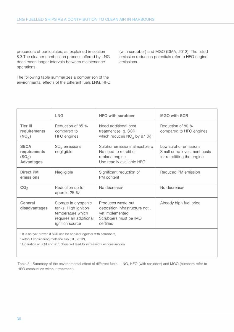
LNG HFO with scrubber MGO with SCR
Tier III Reduction of 85 % Need additional post Reduction of 80 % requirements compared to treatment (e. g. SCR compared to HFO engines(NOx) HFO engines which reduces NOx by 87 %)¹
SECA SOx emissions Sulphur emissions almost zero Low sulphur emissionsrequirements negligible No need to retrofit or Small or no investment costs(SO2) replace engine for retrofitting the engineAdvantages Use readily available HFO
Direct PM Negligible Significant reduction of Reduced PM emissionemissions PM content
CO2 Reduction up to No decrease³ No decrease³approx. 25 %²
General Storage in cryogenic Produces waste but Already high fuel pricedisadvantages tanks. High ignition deposition infrastructure not .
temperature which yet implementedrequires an additional Scrubbers must be IMO ignition source certified
1 It is not yet proven if SCR can be applied together with scrubbers, 2 without considering methane slip (GL, 2012), 3 Operation of SCR and scrubbers will lead to increased fuel consumption
36
LNG FUELLED SHIPS AS A CONTRIBUTION TO CLEAN AIR IN HARBOURS
precursors of particulates, as explained in section8.3.The cleaner combustion process offered by LNGdoes mean longer intervals between maintenanceoperations.
The following table summarizes a comparison of theenvironmental effects of the different fuels LNG, HFO
(with scrubber) and MGO (DMA, 2012). The listedemission reduction potentials refer to HFO engineemissions.
Table 3: Summary of the environmental effect of different fuels - LNG, HFO (with scrubber) and MGO (numbers refer toHFO combustion without treatment)
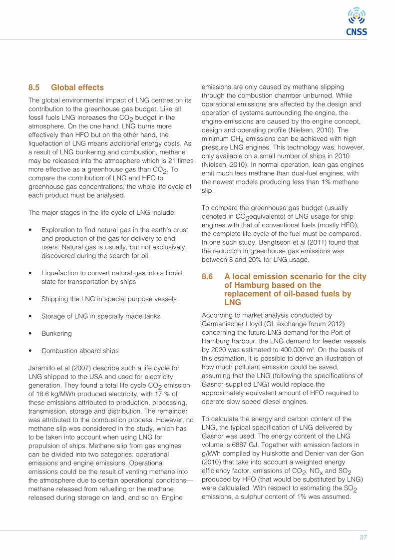
37
8.5 Global effects
The global environmental impact of LNG centres on itscontribution to the greenhouse gas budget. Like allfossil fuels LNG increases the CO2 budget in theatmosphere. On the one hand, LNG burns moreeffectively than HFO but on the other hand, theliquefaction of LNG means additional energy costs. Asa result of LNG bunkering and combustion, methanemay be released into the atmosphere which is 21 timesmore effective as a greenhouse gas than CO2. Tocompare the contribution of LNG and HFO togreenhouse gas concentrations, the whole life cycle ofeach product must be analysed.
The major stages in the life cycle of LNG include:
• Exploration to find natural gas in the earth’s crustand production of the gas for delivery to endusers. Natural gas is usually, but not exclusively,discovered during the search for oil.
• Liquefaction to convert natural gas into a liquidstate for transportation by ships
• Shipping the LNG in special purpose vessels
• Storage of LNG in specially made tanks
• Bunkering
• Combustion aboard ships
Jaramillo et al (2007) describe such a life cycle forLNG shipped to the USA and used for electricitygeneration. They found a total life cycle CO2 emissionof 18.6 kg/MWh produced electricity, with 17 % ofthese emissions attributed to production, processing,transmission, storage and distribution. The remainderwas attributed to the combustion process. However, nomethane slip was considered in the study, which hasto be taken into account when using LNG forpropulsion of ships. Methane slip from gas enginescan be divided into two categories: operationalemissions and engine emissions. Operationalemissions could be the result of venting methane intothe atmosphere due to certain operational conditions—methane released from refuelling or the methanereleased during storage on land, and so on. Engine
emissions are only caused by methane slippingthrough the combustion chamber unburned. Whileoperational emissions are affected by the design andoperation of systems surrounding the engine, theengine emissions are caused by the engine concept,design and operating profile (Nielsen, 2010). Theminimum CH4 emissions can be achieved with highpressure LNG engines. This technology was, however,only available on a small number of ships in 2010(Nielsen, 2010). In normal operation, lean gas enginesemit much less methane than dual-fuel engines, withthe newest models producing less than 1% methaneslip.
To compare the greenhouse gas budget (usuallydenoted in CO2equivalents) of LNG usage for shipengines with that of conventional fuels (mostly HFO),the complete life cycle of the fuel must be compared.In one such study, Bengtsson et al (2011) found thatthe reduction in greenhouse gas emissions wasbetween 8 and 20% for LNG usage.
8.6 A local emission scenario for the cityof Hamburg based on thereplacement of oil-based fuels byLNG
According to market analysis conducted byGermanischer Lloyd (GL exchange forum 2012)concerning the future LNG demand for the Port ofHamburg harbour, the LNG demand for feeder vesselsby 2020 was estimated to 400.000 m3. On the basis ofthis estimation, it is possible to derive an illustration ofhow much pollutant emission could be saved,assuming that the LNG (following the specifications ofGasnor supplied LNG) would replace theapproximately equivalent amount of HFO required tooperate slow speed diesel engines.
To calculate the energy and carbon content of theLNG, the typical specification of LNG delivered byGasnor was used. The energy content of the LNGvolume is 6887 GJ. Together with emission factors ing/kWh compiled by Hulskotte and Denier van der Gon(2010) that take into account a weighted energyefficiency factor, emissions of CO2, NOx and SO2produced by HFO (that would be substituted by LNG)were calculated. With respect to estimating the SO2emissions, a sulphur content of 1% was assumed.
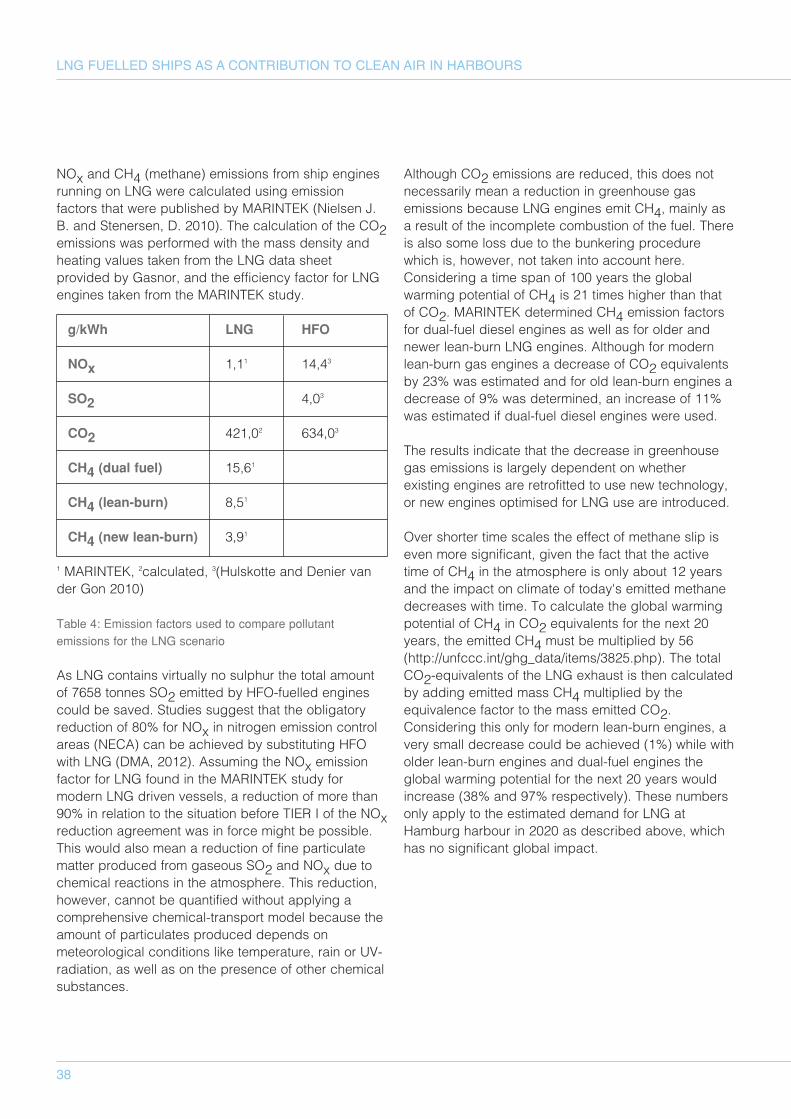
38
LNG FUELLED SHIPS AS A CONTRIBUTION TO CLEAN AIR IN HARBOURS
NOx and CH4 (methane) emissions from ship enginesrunning on LNG were calculated using emissionfactors that were published by MARINTEK (Nielsen J.B. and Stenersen, D. 2010). The calculation of the CO2emissions was performed with the mass density andheating values taken from the LNG data sheetprovided by Gasnor, and the efficiency factor for LNGengines taken from the MARINTEK study.
g/kWh LNG HFO
NOx 1,11 14,43
SO2 4,03
CO2 421,02 634,03
CH4 (dual fuel) 15,61
CH4 (lean-burn) 8,51
CH4 (new lean-burn) 3,91
1 MARINTEK, 2calculated, 3(Hulskotte and Denier vander Gon 2010)
Table 4: Emission factors used to compare pollutantemissions for the LNG scenario
As LNG contains virtually no sulphur the total amountof 7658 tonnes SO2 emitted by HFO-fuelled enginescould be saved. Studies suggest that the obligatoryreduction of 80% for NOx in nitrogen emission controlareas (NECA) can be achieved by substituting HFOwith LNG (DMA, 2012). Assuming the NOx emissionfactor for LNG found in the MARINTEK study formodern LNG driven vessels, a reduction of more than90% in relation to the situation before TIER I of the NOxreduction agreement was in force might be possible.This would also mean a reduction of fine particulatematter produced from gaseous SO2 and NOx due tochemical reactions in the atmosphere. This reduction,however, cannot be quantified without applying acomprehensive chemical-transport model because theamount of particulates produced depends onmeteorological conditions like temperature, rain or UV-radiation, as well as on the presence of other chemicalsubstances.
Although CO2 emissions are reduced, this does notnecessarily mean a reduction in greenhouse gasemissions because LNG engines emit CH4, mainly asa result of the incomplete combustion of the fuel. Thereis also some loss due to the bunkering procedurewhich is, however, not taken into account here.Considering a time span of 100 years the globalwarming potential of CH4 is 21 times higher than thatof CO2. MARINTEK determined CH4 emission factorsfor dual-fuel diesel engines as well as for older andnewer lean-burn LNG engines. Although for modernlean-burn gas engines a decrease of CO2 equivalentsby 23% was estimated and for old lean-burn engines adecrease of 9% was determined, an increase of 11%was estimated if dual-fuel diesel engines were used.
The results indicate that the decrease in greenhousegas emissions is largely dependent on whetherexisting engines are retrofitted to use new technology,or new engines optimised for LNG use are introduced.
Over shorter time scales the effect of methane slip iseven more significant, given the fact that the activetime of CH4 in the atmosphere is only about 12 yearsand the impact on climate of today's emitted methanedecreases with time. To calculate the global warmingpotential of CH4 in CO2 equivalents for the next 20years, the emitted CH4 must be multiplied by 56(http://unfccc.int/ghg_data/items/3825.php). The totalCO2-equivalents of the LNG exhaust is then calculatedby adding emitted mass CH4 multiplied by theequivalence factor to the mass emitted CO2.Considering this only for modern lean-burn engines, avery small decrease could be achieved (1%) while witholder lean-burn engines and dual-fuel engines theglobal warming potential for the next 20 years wouldincrease (38% and 97% respectively). These numbersonly apply to the estimated demand for LNG atHamburg harbour in 2020 as described above, whichhas no significant global impact.
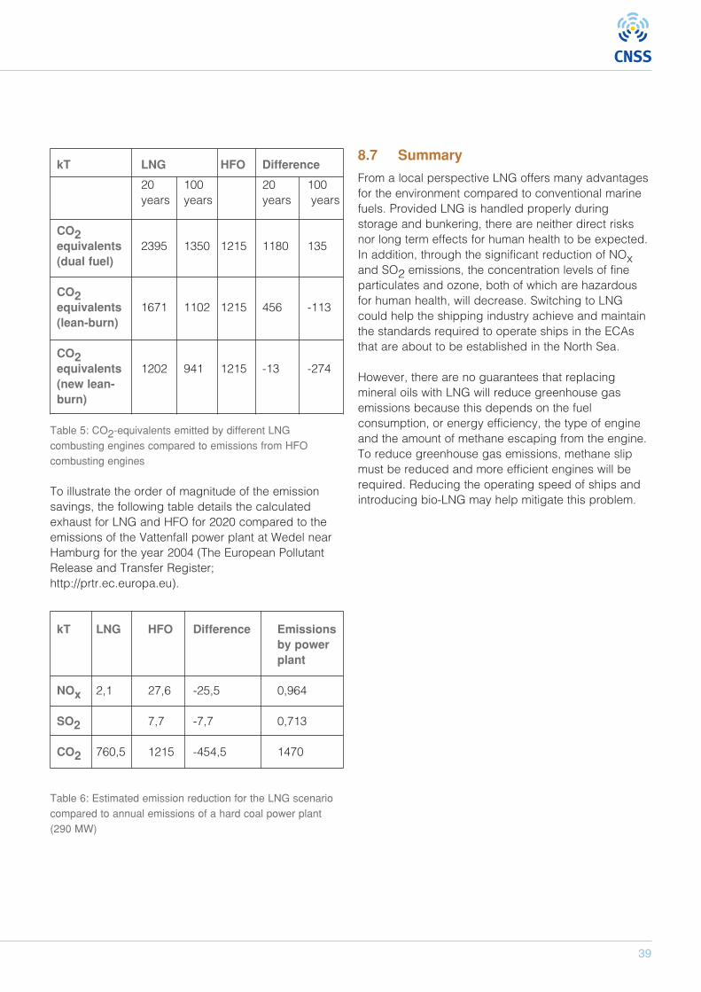
39
kT LNG HFO Difference
20 100 20 100years years years years
CO2equivalents 2395 1350 1215 1180 135(dual fuel)
CO2equivalents 1671 1102 1215 456 -113(lean-burn)
CO2equivalents 1202 941 1215 -13 -274(new lean-burn)
Table 5: CO2-equivalents emitted by different LNGcombusting engines compared to emissions from HFOcombusting engines
To illustrate the order of magnitude of the emissionsavings, the following table details the calculatedexhaust for LNG and HFO for 2020 compared to theemissions of the Vattenfall power plant at Wedel nearHamburg for the year 2004 (The European PollutantRelease and Transfer Register;http://prtr.ec.europa.eu).
kT LNG HFO Difference Emissions by power plant
NOx 2,1 27,6 -25,5 0,964
SO2 7,7 -7,7 0,713
CO2 760,5 1215 -454,5 1470
Table 6: Estimated emission reduction for the LNG scenariocompared to annual emissions of a hard coal power plant(290 MW)
8.7 Summary
From a local perspective LNG offers many advantagesfor the environment compared to conventional marinefuels. Provided LNG is handled properly duringstorage and bunkering, there are neither direct risksnor long term effects for human health to be expected.In addition, through the significant reduction of NOxand SO2 emissions, the concentration levels of fineparticulates and ozone, both of which are hazardousfor human health, will decrease. Switching to LNGcould help the shipping industry achieve and maintainthe standards required to operate ships in the ECAsthat are about to be established in the North Sea.
However, there are no guarantees that replacingmineral oils with LNG will reduce greenhouse gasemissions because this depends on the fuelconsumption, or energy efficiency, the type of engineand the amount of methane escaping from the engine.To reduce greenhouse gas emissions, methane slipmust be reduced and more efficient engines will berequired. Reducing the operating speed of ships andintroducing bio-LNG may help mitigate this problem.

40
LNG FUELLED SHIPS AS A CONTRIBUTION TO CLEAN AIR IN HARBOURS
9.1 The history of LNG
LNG has been produced commercially since 1940 asa method of transporting stranded natural gas toconsumers where distribution via pipeline for variousreasons was not possible. The market for LNG hasbeen characterised by long term, large volumecontracts between limited numbers of major players.Many of these players are states or state-ownedcompanies with the LNG used as the main oralternative source of supply for natural gas to gas gridconnected consumers. LNG has in principle neverbeen sold directly to end users and the spot market ofLNG has been infinite.
The price of natural gas has been closely connected tothe price of crude oil, partly as a result of their sharedhistory. Natural gas usually originates from“associated” fields, and is often produced togetherwith crude oil. Since the economics of oil and gasproduction are very similar, the price of gas hastraditionally been closely linked to the price of oil.However, more importantly, it was interfuel substitution,at the other end of the value chain, which really linkedoil and gas prices for many years. Interfuel substitutionsimply means that two fuels could be used for thesame purposes, for example for residential heating orelectricity generation. Consequently, the similareconomics of upstream production and the fact that oiland gas products have been close substitutes,resulted in the close correlation of oil and gas prices.
A similar correlation is also valid, according to Habibet al (2012), for pricing LNG for the long term supplycontracts characteristic the LNG trade where the price
of LNG is usually linked to crude oil.
In Figure 25 the correlation between natural gas andcrude oil prices is plotted against the time period from1984 until the end of the first decade of the 21st
century. During that period the correlation betweencrude and natural gas is very close until 2005-2006 butafter 2006 the prices begin to diverge. Two significantcauses, discussed later in this chapter, have beenidentified:
• A price disassociation between crude and naturalgas
• Increasing regional price differences for naturalgas
9.2 Increase in availability
9.2.1 Global trends
During the last five to seven years there has been asignificant increase in the availability of natural gas(NG) in the fuel market. This has resulted from acombination of new technical developments withrespect to the exploration of so-called shale gas andsignificant investments in new production anddistribution facilities for traditional natural gas sourcesin Australia, India, Qatar, Saudi Arabia, Iran, China andso on (see Table 7). The total production of NG was about 3300 billion m3 in2011, with the total increase in production during theperiod 2006 to 2011 about 12,4% according to BP(2012). During the same time period the annualproduction of crude oil only increased with 1,7 %.
9 LNG Market overview
Figure 25: The development of prices for natural gas and crude oil (Source: BP Statistical Review of World Energy June 2012)
The development of prices for natural gas and crude oil
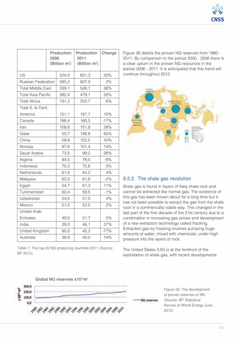
41
Production Production Change2006 2011(Billion m3) (Billion m3)
US 524,0 651,3 20%
Russian Federation 595,2 607,0 2%
Total Middle East 339,1 526,1 36%
Total Asia Pacific 382,4 479,1 20%
Total Africa 191,2 202,7 6%
Total S. & Cent.
America 151,1 167,7 10%
Canada 188,4 160,5 -17%
Iran 108,6 151,8 28%
Qatar 50,7 146,8 65%
China 58,6 102,5 43%
Norway 87,6 101,4 14%
Saudi Arabia 73,5 99,2 26%
Algeria 84,5 78,0 -8%
Indonesia 70,3 75,6 0%
Netherlands 61,6 64,2 4%
Malaysia 63,3 61,8 -2%
Egypt 54,7 61,3 11%
Turkmenistan 60,4 59,5 -1%
Uzbekistan 54,5 57,0 4%
Mexico 51,5 52,5 2%
United Arab
Emirates 49,0 51,7 5%
India 29,3 46,1 37%
United Kingdom 80,0 45,2 -77%
Australia 38,9 45,0 14%
Table 7: The top 20 NG producing countries 2011 (Source:BP 2012)
Figure 26 details the proven NG reserves from 1980 -2011. By comparison to the period 2000 - 2006 there isa clear upturn in the proven NG resources in theperiod 2006 - 2011. It is anticipated that this trend willcontinue throughout 2012.
9.2.2 The shale gas revolution
Shale gas is found in layers of flaky shale rock andcannot be extracted like normal gas. The existence ofthis gas has been known about for a long time but ithas not been possible to extract the gas from the shalerock in a commercially viable way. This changed in thelast part of the first decade of the 21st century due to acombination in increasing gas prices and developmentof a new extraction technology called fracking.Extraction gas by fracking involves pumping hugeamounts of water, mixed with chemicals, under highpressure into the layers of rock.
The United States (US) is at the forefront of theexploitation of shale gas, with recent developments
Figure 26: The developmentof proven reserves of NG(Source: BP StatisticalReview of World Energy June2012)
Global NG reserves x1012m3

42
LNG FUELLED SHIPS AS A CONTRIBUTION TO CLEAN AIR IN HARBOURS
resulting in rapid increases their domestic productionof natural gas. Previously the world’s biggest netimporter of natural gas, the US are set become a netexporter of the fuel. According to both BP, 2012 andIEA, 2012, 2012 is expected to be the first year the USproduces more natural gas then is consumeddomestically.
As a result US imports of both pipeline gas, and moresignificantly, LNG have declined to approximately 3%of the total import market in 2011 (see Figure 27).Since the US market was traditionally one of the mainmarkets for LNG imports, accounting for about 10% ofthe total LNG import market in 2007, significantvolumes of LNG are now available on the open market.
Shale gas is also available in other countries but theexploration of these resources is not as developed asin the US. China, for example, is presumed to haveeven larger shale gas reserves than the US and ifthese expectations actually materialise, China will havea significant impact on the natural gas and LNGmarkets. Over the last five years, China has gone froma natural gas exporter to become one of the largestnatural gas importers in the world, with continuouslygrowing natural gas consumption.
However, there are a number of obvious down sides tothe current shale gas bonanza including the
environmental and health concerns related to theexplorations methods. Little research has beenundertaken to establish the effects, both long-term andshort-term, of the procedures and chemicals used infracking. Aside from these two issues, compared toconventional gas extraction, more methane isdischarged during the process, which is a powerfuland damaging greenhouse gas. These three concernsresulted in the French authorities putting a temporaryban on fracking in 2011.
9.3 Regional pricing imbalance
In addition to the price disassociation from crude oilthere is also another clear development visible inFigure 27 and that is the significant, and increasing,regional differences in NG pricing. The main reason forthis is the shortage of the necessary infrastructure tomove NG from one market to another. As previouslystated LNG is the main conduit for transporting NG butsince most of the available infrastructure has beenpurpose built for specific flows and the usage andaccess to the necessary land-based infrastructure isheavily regulated in some markets, it has been verydifficult to redirect LNG from markets with adecreasing demand, such as North America andEurope, to markets with an increasing demand such asNorth East Asia, China, India and so on. This hascreated a situation where the NG prices haveincreased almost exponentially in some markets, such
Figure 27: Annual US LNG Imports (Source: EIA website, 2012)
U.S. Liquefied Natural Gas Imports (million m3)
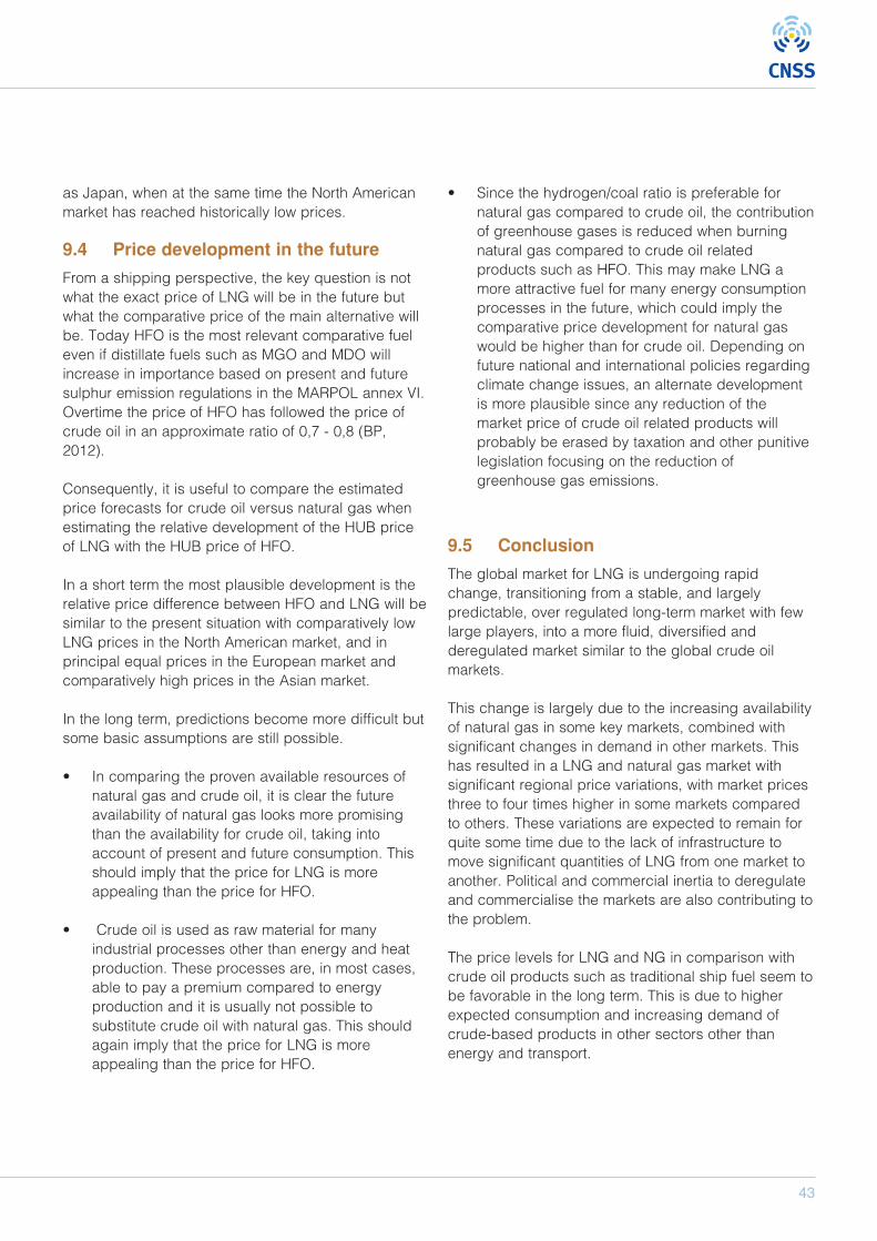
43
as Japan, when at the same time the North Americanmarket has reached historically low prices.
9.4 Price development in the future
From a shipping perspective, the key question is notwhat the exact price of LNG will be in the future butwhat the comparative price of the main alternative willbe. Today HFO is the most relevant comparative fueleven if distillate fuels such as MGO and MDO willincrease in importance based on present and futuresulphur emission regulations in the MARPOL annex VI.Overtime the price of HFO has followed the price ofcrude oil in an approximate ratio of 0,7 - 0,8 (BP,2012).
Consequently, it is useful to compare the estimatedprice forecasts for crude oil versus natural gas whenestimating the relative development of the HUB priceof LNG with the HUB price of HFO.
In a short term the most plausible development is therelative price difference between HFO and LNG will besimilar to the present situation with comparatively lowLNG prices in the North American market, and inprincipal equal prices in the European market andcomparatively high prices in the Asian market.
In the long term, predictions become more difficult butsome basic assumptions are still possible.
• In comparing the proven available resources ofnatural gas and crude oil, it is clear the futureavailability of natural gas looks more promisingthan the availability for crude oil, taking intoaccount of present and future consumption. Thisshould imply that the price for LNG is moreappealing than the price for HFO.
• Crude oil is used as raw material for manyindustrial processes other than energy and heatproduction. These processes are, in most cases,able to pay a premium compared to energyproduction and it is usually not possible tosubstitute crude oil with natural gas. This shouldagain imply that the price for LNG is moreappealing than the price for HFO.
• Since the hydrogen/coal ratio is preferable fornatural gas compared to crude oil, the contributionof greenhouse gases is reduced when burningnatural gas compared to crude oil relatedproducts such as HFO. This may make LNG amore attractive fuel for many energy consumptionprocesses in the future, which could imply thecomparative price development for natural gaswould be higher than for crude oil. Depending onfuture national and international policies regardingclimate change issues, an alternate developmentis more plausible since any reduction of themarket price of crude oil related products willprobably be erased by taxation and other punitivelegislation focusing on the reduction ofgreenhouse gas emissions.
9.5 Conclusion
The global market for LNG is undergoing rapidchange, transitioning from a stable, and largelypredictable, over regulated long-term market with fewlarge players, into a more fluid, diversified andderegulated market similar to the global crude oilmarkets.
This change is largely due to the increasing availabilityof natural gas in some key markets, combined withsignificant changes in demand in other markets. Thishas resulted in a LNG and natural gas market withsignificant regional price variations, with market pricesthree to four times higher in some markets comparedto others. These variations are expected to remain forquite some time due to the lack of infrastructure tomove significant quantities of LNG from one market toanother. Political and commercial inertia to deregulateand commercialise the markets are also contributing tothe problem.
The price levels for LNG and NG in comparison withcrude oil products such as traditional ship fuel seem tobe favorable in the long term. This is due to higherexpected consumption and increasing demand ofcrude-based products in other sectors other thanenergy and transport.
U.S. Liquefied Natural Gas Imports (million m3)
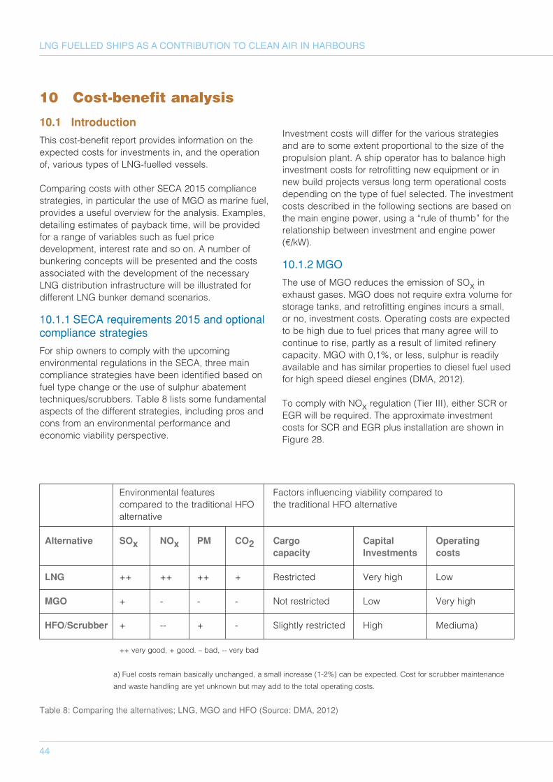
44
LNG FUELLED SHIPS AS A CONTRIBUTION TO CLEAN AIR IN HARBOURS
10.1 Introduction
This cost-benefit report provides information on theexpected costs for investments in, and the operationof, various types of LNG-fuelled vessels.
Comparing costs with other SECA 2015 compliancestrategies, in particular the use of MGO as marine fuel,provides a useful overview for the analysis. Examples,detailing estimates of payback time, will be providedfor a range of variables such as fuel pricedevelopment, interest rate and so on. A number ofbunkering concepts will be presented and the costsassociated with the development of the necessaryLNG distribution infrastructure will be illustrated fordifferent LNG bunker demand scenarios.
10.1.1 SECA requirements 2015 and optionalcompliance strategies
For ship owners to comply with the upcomingenvironmental regulations in the SECA, three maincompliance strategies have been identified based onfuel type change or the use of sulphur abatementtechniques/scrubbers. Table 8 lists some fundamentalaspects of the different strategies, including pros andcons from an environmental performance andeconomic viability perspective.
Investment costs will differ for the various strategiesand are to some extent proportional to the size of thepropulsion plant. A ship operator has to balance highinvestment costs for retrofitting new equipment or innew build projects versus long term operational costsdepending on the type of fuel selected. The investmentcosts described in the following sections are based onthe main engine power, using a “rule of thumb” for therelationship between investment and engine power(€/kW).
10.1.2 MGO
The use of MGO reduces the emission of SOx inexhaust gases. MGO does not require extra volume forstorage tanks, and retrofitting engines incurs a small,or no, investment costs. Operating costs are expectedto be high due to fuel prices that many agree will tocontinue to rise, partly as a result of limited refinerycapacity. MGO with 0,1%, or less, sulphur is readilyavailable and has similar properties to diesel fuel usedfor high speed diesel engines (DMA, 2012).
To comply with NOx regulation (Tier III), either SCR orEGR will be required. The approximate investmentcosts for SCR and EGR plus installation are shown inFigure 28.
10 Cost-benefit analysis
Environmental features Factors influencing viability compared tocompared to the traditional HFO the traditional HFO alternativealternative
Alternative SOx NOx PM CO2 Cargo Capital Operating capacity Investments costs
LNG ++ ++ ++ + Restricted Very high Low
MGO + - - - Not restricted Low Very high
HFO/Scrubber + -- + - Slightly restricted High Mediuma)
++ very good, + good. – bad, -- very bad
a) Fuel costs remain basically unchanged, a small increase (1-2%) can be expected. Cost for scrubber maintenance
and waste handling are yet unknown but may add to the total operating costs.
Table 8: Comparing the alternatives; LNG, MGO and HFO (Source: DMA, 2012)
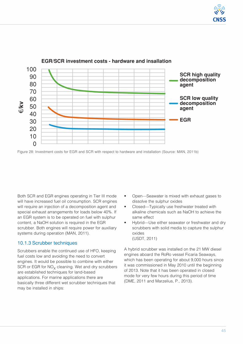
45
0 10 20 30 40 50 60 70 80
1009080706050403020100
€/kv
EGR/SCR investment costs - hardware and insallation
SCR high qualitydecompositionagent
SCR low qualitydecompositionagent
EGR
Engine size (MW)Figure 28: Investment costs for EGR and SCR with respect to hardware and installation (Source: MAN, 2011b)
Both SCR and EGR engines operating in Tier III modewill have increased fuel oil consumption. SCR engineswill require an injection of a decomposition agent andspecial exhaust arrangements for loads below 40%. Ifan EGR system is to be operated on fuel with sulphurcontent, a NaOH solution is required in the EGRscrubber. Both engines will require power for auxiliarysystems during operation (MAN, 2011).
10.1.3 Scrubber techniques
Scrubbers enable the continued use of HFO, keepingfuel costs low and avoiding the need to convertengines. It would be possible to combine with eitherSCR or EGR for NOx cleaning. Wet and dry scrubbersare established techniques for land-basedapplications. For marine applications there arebasically three different wet scrubber techniques thatmay be installed in ships:
• Open—Seawater is mixed with exhaust gases todissolve the sulphur oxides
• Closed—Typically use freshwater treated withalkaline chemicals such as NaOH to achieve thesame effect
• Hybrid—Use either seawater or freshwater and dryscrubbers with solid media to capture the sulphuroxides (USDT, 2011)
A hybrid scrubber was installed on the 21 MW dieselengines aboard the RoRo vessel Ficaria Seaways,which has been operating for about 9,000 hours sinceit was commissioned in May 2010 until the beginningof 2013. Note that it has been operated in closedmode for very few hours during this period of time(DME, 2011 and Marzelius, P., 2013).
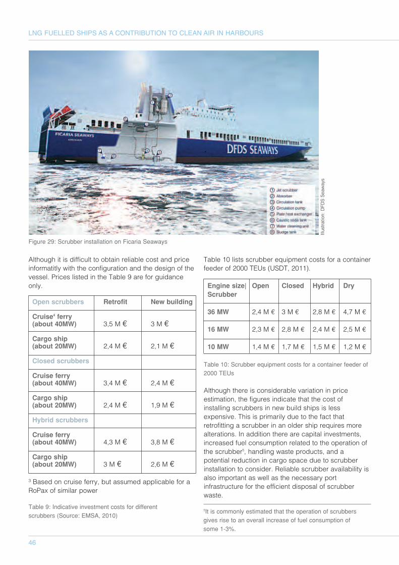
46
LNG FUELLED SHIPS AS A CONTRIBUTION TO CLEAN AIR IN HARBOURS
Although it is difficult to obtain reliable cost and priceinformatitly with the configuration and the design of thevessel. Prices listed in the Table 9 are for guidanceonly.
Open scrubbers Retrofit New building
Cruise4 ferry (about 40MW) 3,5 M € 3 M €
Cargo ship (about 20MW) 2,4 M € 2,1 M €
Closed scrubbers
Cruise ferry (about 40MW) 3,4 M € 2,4 M €
Cargo ship (about 20MW) 2,4 M € 1,9 M €
Hybrid scrubbers
Cruise ferry (about 40MW) 4,3 M € 3,8 M €
Cargo ship (about 20MW) 3 M € 2,6 M €
³ Based on cruise ferry, but assumed applicable for aRoPax of similar power
Table 10 lists scrubber equipment costs for a containerfeeder of 2000 TEUs (USDT, 2011).
Engine size| Open Closed Hybrid DryScrubber
36 MW 2,4 M € 3 M € 2,8 M € 4,7 M €
16 MW 2,3 M € 2,8 M € 2,4 M € 2,5 M €
10 MW 1,4 M € 1,7 M € 1,5 M € 1,2 M €
Table 10: Scrubber equipment costs for a container feeder of2000 TEUs
Although there is considerable variation in priceestimation, the figures indicate that the cost ofinstalling scrubbers in new build ships is lessexpensive. This is primarily due to the fact thatretrofitting a scrubber in an older ship requires morealterations. In addition there are capital investments,increased fuel consumption related to the operation ofthe scrubber5, handling waste products, and apotential reduction in cargo space due to scrubberinstallation to consider. Reliable scrubber availability isalso important as well as the necessary portinfrastructure for the efficient disposal of scrubberwaste.
Figure 29: Scrubber installation on Ficaria Seaways
Table 9: Indicative investment costs for differentscrubbers (Source: EMSA, 2010)
5It is commonly estimated that the operation of scrubbersgives rise to an overall increase of fuel consumption ofsome 1-3%.
Illustration: DFDS Seaways

47
The operating and maintenance costs for scrubbershave been estimated at 0.0025 €/kWmainh (based onenergy main engine power [kW] * time at sea[hours/year]). Personnel and indirect costs areincluded and scaled from an assumed cost ofapproximately 40 000 €/year for a ship operating 6 000hours (DMA, 2012).
10.1.4 LNG - basic engine technique, fueltanks and bunkering solutions
Gas engines are a proven, reliable alternative but theyrequire technical fitting and optimisation. For example,LNG storage tanks require more space than traditionalfuel oil tanks, which may reduce cargo capacitydepending on type of vessel, the type of fuel tank andavailability of a suitable location for the LNG tanksonboard ship. Handling LNG also incurs additionalcosts due to the lack of existing infrastructure.
The three main LNG bunkering methods are:
• Truck-to-ship (TTS) • Land based tank-to-ship (TPS) • Ship-to-ship (STS)
Each bunkering method requires a different supplychain hence the varying investment costs (refer to theexample in 10.3 LNG fuel supply infrastructure).
Method Pro ConTTS Limited initial costs Limited capacity
Use for other Impact to parallel purposes operation
Need quayConnection by road to LNG source
TPS Variation of tank Not flexiblecapacity bunkering locationSupply by truck Space and safety or ship requirements
STS Flexible Investment costs for bunker vesselInfrastructure investments – efficient useAlternative use for bunker vessel
10.1.4.1 Dual Fuel and Pure Gas
LNG may be used for engines that are able to run oneither liquid fuel oils or gaseous fuel, designed aseither 4-stroke or 2-stroke engines. This meansdifferent fuels can be used for propulsion dependingon whether the ship is inside or outside the SECA.Relative fuel prices will determine the type of fuel usedoutside the SECA.
When operating on natural gas, 4-stroke engines arebased on the Otto cycle, whereas the Diesel cycle isused by the engine when operating on fuel oils. Theignition source is a small amount of fuel oil which isinjected and ignited by the compression heat—theburning oil ignites the gas. The 2-stroke enginecombines a high pressure gas injection together withpilot diesel oil and the fuel oil ignites first—the gas isignited in turn by the burning fuel oil. The 2-strokeengine can run on fuel oil only or on a mixture of gasand fuel oil and therefore has no, or almost no,methane slip.
Pure gas engines cannot use any kind of oil-basedfuel. Most of the gas engines in use today are the
Otto/Miller type6 with spark ignition. This technologyensures high efficiency and low emissions (DMA,2012).
6A traditional Otto cycle engine uses four "strokes", of whichtwo can be considered "high power" — the compressionstroke (high power consumption) and power stroke (highpower production). Much of the internal power loss of anengine is due to the energy needed to compress the chargeduring the compression stroke, so systems that reduce thispower consumption can lead to greater efficiency.
In the Miller cycle, the intake valve is left open longer than itwould be in an Otto cycle engine. In effect, the compressionstroke is two discrete cycles—the initial portion when theintake valve is open and final portion when the intake valveis closed. This two-stage intake stroke creates the so called"fifth" stroke that the Miller cycle introduces.
Table 11: Pros and cons of different LNG bunkeringsolutions (Source: DMA, 2012)
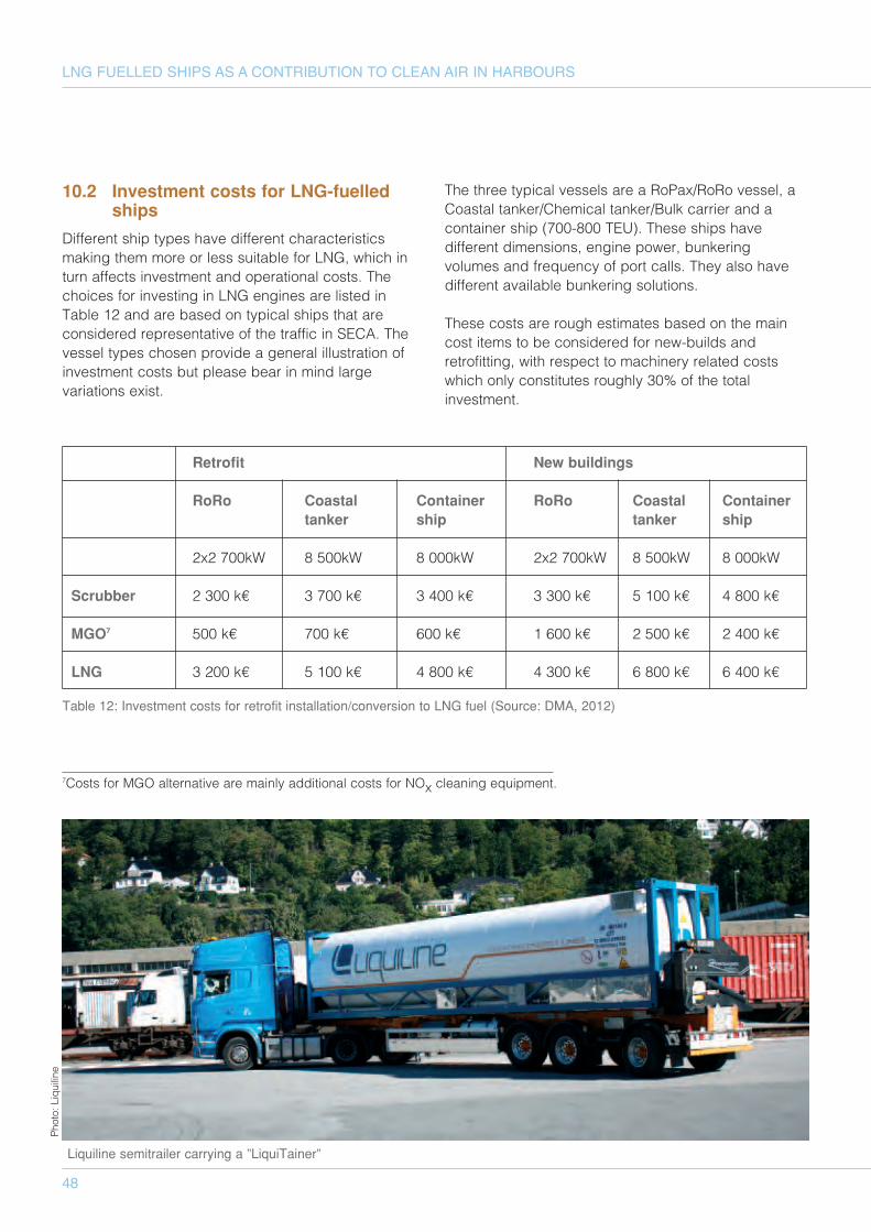
48
LNG FUELLED SHIPS AS A CONTRIBUTION TO CLEAN AIR IN HARBOURS
10.2 Investment costs for LNG-fuelledships
Different ship types have different characteristicsmaking them more or less suitable for LNG, which inturn affects investment and operational costs. Thechoices for investing in LNG engines are listed inTable 12 and are based on typical ships that areconsidered representative of the traffic in SECA. Thevessel types chosen provide a general illustration ofinvestment costs but please bear in mind largevariations exist.
The three typical vessels are a RoPax/RoRo vessel, aCoastal tanker/Chemical tanker/Bulk carrier and acontainer ship (700-800 TEU). These ships havedifferent dimensions, engine power, bunkeringvolumes and frequency of port calls. They also havedifferent available bunkering solutions.
These costs are rough estimates based on the maincost items to be considered for new-builds andretrofitting, with respect to machinery related costswhich only constitutes roughly 30% of the totalinvestment.
Retrofit New buildings
RoRo Coastal Container RoRo Coastal Containertanker ship tanker ship
2x2 700kW 8 500kW 8 000kW 2x2 700kW 8 500kW 8 000kW
Scrubber 2 300 k€ 3 700 k€ 3 400 k€ 3 300 k€ 5 100 k€ 4 800 k€
MGO7 500 k€ 700 k€ 600 k€ 1 600 k€ 2 500 k€ 2 400 k€
LNG 3 200 k€ 5 100 k€ 4 800 k€ 4 300 k€ 6 800 k€ 6 400 k€
Table 12: Investment costs for retrofit installation/conversion to LNG fuel (Source: DMA, 2012)
7Costs for MGO alternative are mainly additional costs for NOx cleaning equipment.
Liquiline semitrailer carrying a ”LiquiTainer”
Photo: Liquiline
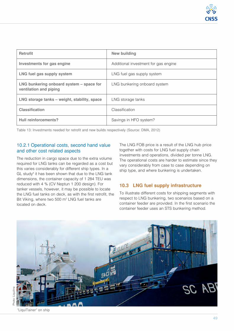
49
Retrofit New building
Investments for gas engine Additional investment for gas engine
LNG fuel gas supply system LNG fuel gas supply system
LNG bunkering onboard system – space for LNG bunkering onboard systemventilation and piping
LNG storage tanks – weight, stability, space LNG storage tanks
Classification Classification
Hull reinforcements? Savings in HFO system?
Table 13: Investments needed for retrofit and new builds respectively (Source: DMA, 2012)
10.2.1 Operational costs, second hand valueand other cost related aspects
The reduction in cargo space due to the extra volumerequired for LNG tanks can be regarded as a cost butthis varies considerably for different ship types. In aGL study8 it has been shown that due to the LNG tankdimensions, the container capacity of 1 284 TEU wasreduced with 4 % (CV Neptun 1 200 design). Fortanker vessels, however, it may be possible to locatethe LNG fuel tanks on deck, as with the first retrofit, theBit Viking, where two 500 m3 LNG fuel tanks arelocated on deck.
The LNG FOB price is a result of the LNG hub pricetogether with costs for LNG fuel supply chaininvestments and operations, divided per tonne LNG.The operational costs are harder to estimate since theyvary considerably from case to case depending onship type, and where bunkering is undertaken.
10.3 LNG fuel supply infrastructure
To illustrate different costs for shipping segments withrespect to LNG bunkering, two scenarios based on acontainer feeder are provided. In the first scenario thecontainer feeder uses an STS bunkering method.
”LiquiTainer” on ship
Photo: Liquiline
LNG fuel supply chain
LNG SourceGBG 373 €/tonnes LNG price in Gothenburg
LNG Tank truck 13 €/tonnes Three trucks active in Gothenburg can supply the 10 container feeders
FOB 316 €/tonnes LNG SourceGBG+LNG Tank truck * Net calorific value for HFO is 82% of LNG (IMO, 2012)
FOB MGO 762 €/tonnes Comparative FOB price for MGO in Gothenburg
Table 15: FOB Cost of LNG delivered TTS
50
LNG FUELLED SHIPS AS A CONTRIBUTION TO CLEAN AIR IN HARBOURS
8 IMO Caribbean, 20129 The example of container feeder, ship size, FOC and LNG demand are referenced to DMA, 2012.10 Based on a 5 000 tonnes LNG feeder en route Rotterdam-Gothenburg, 31 000 €/day (IMO, 2012).
Table 14: FOB cost of LNG delivered STS
Container feeder9
Scope Container feeder engaged in 7-days routes between St- Petersburg, Stockholm, Malmö-Copenhagen and Gothenburg.
Ship size 9 000 dtw, 800 TEU
Fuel consumption 12,3 tonnes LNG/day. Operating on average 12 h/day with 18 knots is6,2 tonnes /day10
Route Total travelled distance 3 000 nautical miles per route
Number of vessels 10 in 2015, 30 in 2025
Bunkering method STS, available bunkering time 6-12 hours
LNG demand 4 500 tonnes LNG/year in 2015, 13 500 tonnes LNG/year in 2025
LNG fuel supply chain fuel supply chain
LNG sourceROTTERDAM 295 €/tonnes LNG price in Europe
Transport to GBG 39 €/tonnes Additional cost for transportation10
Storage in GBG 39 €/tonnes Additional cost for storage
LNG Source GBG 373 €/tonnes LNG price in Gothenburg
LNG Bunker vessel 225 €/tonnes Costs for a small bunker vessel (~70 tonnes) is approximately 14 000€/day
FOB 493 €/tonnes LNG SourceGBG+LNG Bunker vessel * Net calorific value for HFO (82% of LNG) (IMO, 2012)
FOB MGO 762 €/tonnes Comparative FOB price for MGO in Gothenburg
In the second scenario the same container feeder uses a TTS bunkering method, which has an impact on theLNG supply chain and the FOB price.
51
11 Knowledge, training and certification
The on-going paradigm shift from oil to LNG as marinefuel is a technical, environmental and regulatory shift. Italso implies a significant change in the knowledge andtraining required by the various professionals who dealwith shipping on a regular basis. The following chapteridentifies several different groups of professionals whowill be affected by these changes and also providessome indication of the current levels of generalknowledge and awareness of the implications of usingLNG as marine fuel among these groups. It will alsoprovide some recommendations for the projectstakeholders as to what action will be required tosecure the availability of professionals with theappropriate knowledge to meet the future demands.
11.1 Crew on IGF vessels
11.1.1 Existing regulatory framework
The main regulatory body for all commercial vessels ininternational trade is the IMO, a member organisationand a part of the UN. Today the IMO has 170 memberstates and three Associate Members. There are also anumber of IGOs and NGOs that have cooperative orconsultative status in relation to the IMO.
The IMO regulates international shipping activitiesthrough a number of conventions. These conventionsare not laws as the IMO has no authority to enforcethem. Instead it is up to each member state to applythe conventions within the context of each nationalregulatory framework. When a new or revised versionof a convention is published, a formal approvalprocess is initiated among the member states. Thisprocess will vary depending on the extent of thechange but in principle each member state thataccepts or approves a new or changed conventionhas to adopt it as part of their national legal system.This must be in line with a number of conditionsspecified in the basic framework of rules andregulations of IMO membership. Further informationabout how the IMO regulates international shipping isavailable on the IMO webpage.
When it comes to the regulations governing theeducation and training for the crew of commercialvessels involved in international trade, the main IMOconvention is the STCW convention. The latest versionof this convention, the 2011 edition, included no rulesor regulations concerning educational standards for
the crew onboard IGF vessels. The main responsibilityfor the development of the STCW convention is theIMO sub-committee STW.
In Chapter 8 of IMO Resolution MSC.285(86) somebasic operational and training requirements arespecified. As with the rest of the resolution,MSC.285(86) is based on work undertaken by theNorwegian authorities since the late 20th century, andhas been developed into an IMO resolution by the IMOBLG sub-committee.
11.1.2 Common Practice
Since the IMO Resolution MSC285(86) is non-compulsory and there are no rules or regulationsstated in the present STCW convention, it is up to eachmember state to decide on the educational andtraining standards for crew operating vessels flying itsflag. Up until now all member states that operate IGFvessels have used the requirements in the interimguidelines as a starting point, and the furtherrequirements for education and training are usuallydeveloped for specific vessels on a case-by-casebasis. In the absence a more general andinternationally adopted set of rules and regulations,this ad-hoc approach to education and training willprobably persist in the near future too.
11.1.3 On-going activities
At the last meeting of STW, STW43 held in late April2012, the topic of regulation for education and trainingfor IGF vessels was addressed by BLG as a result ofBLG16 in relation to the development of the IGF codeas described in section 5.1.5. In principal STW43appreciated the topic raised by the BLG16 but due tothe fact that the topic was sent to the STW shortlybefore the STW43 meeting, STW43 didn’t take anyimmediate action during the meeting since the topicwasn't properly prepared. Instead STW43 invitedMember Governments of the STW to consider thematter in detail and submit comments and proposals toSTW44, planned for 13-17 May 2013.
Within the LNG ship fuel advisory group, described insection 5.3.2, work has begun to develop trainingrequirements for IGF vessels and the group aims tohave something ready to STW44. The development isled by Warsash Maritime Academy in Southampton,UK.
52
LNG FUELLED SHIPS AS A CONTRIBUTION TO CLEAN AIR IN HARBOURS
11.1.4 Recommendations
A number of different studies that have beenperformed in relation to the development of LNG asmarine fuel, such as the LNG northern EuropeInfrastructure project, have identified training for crewhas as one of the main areas that requiresdevelopment. Safety concerns and the risk ofdeveloping a shortfall in suitably trained crew werecited as the main reasons.
Since shipping is a truly international business, it isimportant that all initiatives seeking to addresseducation and training needs work to produce acommon international standard for training of IGFcrews. The best forum to do this is the STW committeewithin the IMO, and member state authorities, NGO sand other relevant stakeholders are encouraged tofocus its efforts on getting the necessary requirementsinto the next amendment of the STCW convention.
11.2 Bunker vessels crew
11.2.1 Exiting regulatory framework
In contrast to IGF vessels there is already a validinternational regulatory framework for the requiredtraining and certification of crew working on LNGbunker vessels in the STCW convention, with the maindemands are defined in Regulation V/1-2. All memberstates that have ratified the STCW convention areobliged to follow the minimum standard of competenceas defined in the convention. However, any memberstate may impose higher standards than defined in theSTCW convention if required.
In principle there are two types of certificates—general and special. The general certificates arerelated to the vessel itself and have nothing to do withwhat the type of cargo handled. Special certificatesare specifically for the type of cargo handled, andgenerally apply to tankers as well as passengervessels.
To serve in any position with specific assigned dutiesand responsibilities related to cargo, or cargoequipment, on an LNG bunker vessel, crew must holda special certificate in basic training for liquefied gastanker cargo operations in addition to the basiccertification of the position held onboard. To qualify forthis certificate, crew members need at least three
months of approved seagoing time as well as theparticipation in a basic training course approved by amember state.
To serve in any position with immediate responsibilityin relation to cargo and cargo handling, crew musthold a special certificate in advanced training. Inaddition to the requirements related to the basictraining, crew must have either at least three months ofapproved seagoing service time on a liquefied gastanker, or one month in a supernumerary capacityincluding not less than three loading and threedischarging operations. Crew are also required toparticipate in an advanced training course approvedby a member state. Note that all crew must hold abasic training certificate before they are allowed tobegin the training or seagoing time for the advancedcertificate.
11.2.2 Availability
If the demand for LNG as a general marine fuel growsrapidly, the demand for LNG bunker vessels also willgrow in the same pace. If bunker vessel operators aregoing to meet these demands, they will requirecertified crew members.
Section 11.2.1 outlined the basic steps to acquire thenecessary certificates to serve in any position onboardan LNG bunker vessel. It will be necessary for seniorofficers to complete four to six months of approvedseagoing time to qualify for the advanced certificate,and a minimum of three months of approved seagoingtime for all crew assigned any kind of duty related tocargo handling and cargo equipment.
Since the global numbers of liquefied gas tankers arecurrently limited, the numbers of seafarers with therequired certificates are also limited. The number oftraining positions onboard these vessels is alsorestricted since each vessel can only accommodate afew extra crew members. This implies that based onpresent regulations, it will be difficult to react quickly tothe changing demands for an increased number ofcertified seafarers for the LNG marine fuel market.
11.2.3 Recommendation
If the LNG marine fuel market takes off, there is asignificant risk of a shortage of certified seafarers forLNG bunker vessels. Member state authorities, NGO’s,
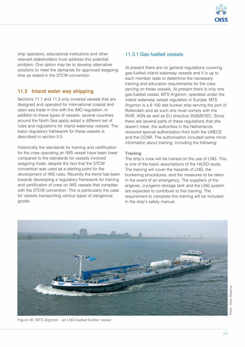
53
ship operators, educational institutions and otherrelevant stakeholders must address this potentialproblem. One option may be to develop alternativesolutions to meet the demands for approved seagoingtime as stated in the STCW convention.
11.3 Inland water way shipping
Sections 11.1 and 11.2 only covered vessels that aredesigned and operated for international coastal andopen sea trade in line with the IMO regulation. Inaddition to these types of vessels, several countriesaround the North Sea apply adopt a different set ofrules and regulations for inland waterway vessels. Thebasic regulatory framework for these vessels isdescribed in section 5.5.
Historically the standards for training and certificationfor the crew operating an IWS vessel have been lowercompared to the standards for vessels involvedseagoing trade, despite the fact that the STCWconvention was used as a starting point for thedevelopment of IWS rules. Recently the trend has beentowards developing a regulatory framework for trainingand certification of crew on IWS vessels that complieswith the STCW convention. This is particularly the casefor vessels transporting various types of dangerousgoods.
11.3.1 Gas-fuelled vessels
At present there are no general regulations coveringgas-fuelled inland waterway vessels and it is up toeach member state to determine the necessarytraining and education requirements for the crewserving on these vessels. At present there is only onegas-fuelled vessel, MTS Argonon, operated under theinland waterway vessel regulation in Europe. MTSArgonon is a 6 100 dwt bunker ship serving the port ofRotterdam and as such she must comply with theRVIR, ADN as well as EU directive 2006/87/EC. Sincethere are several parts of these regulations that shedoesn’t meet, the authorities in the Netherlandsreceived special authorization from both the UNECEand the CCNR. The authorisation included some minorinformation about training, including the following:
TrainingThe ship's crew will be trained on the use of LNG. Thisis one of the basic assumptions of the HAZID study.The training will cover the hazards of LNG, thebunkering procedures, and the measures to be takenin the event of an emergency. The suppliers of theengines, cryogenic storage tank and the LNG systemare expected to contribute to this training. Therequirement to complete this training will be includedin the ship's safety manual.
Figure 30: MTS Argonon - an LNG-fuelled bunker vessel
Photo: Deen Shipping
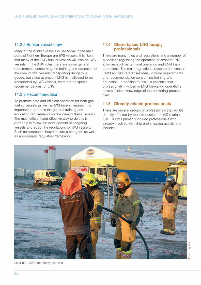
54
LNG FUELLED SHIPS AS A CONTRIBUTION TO CLEAN AIR IN HARBOURS
11.3.2 Bunker vessel crew
Many of the bunker vessels in use today in the mainports of Northern Europe are IWS vessels. It is likelythat many of the LNG bunker vessels will also be IWSvessels. In the ADN rules there are some generalrequirements concerning the training and education ofthe crew of IWS vessels transporting dangerousgoods, but since at present LNG isn’t allowed to betransported by IWS vessels, there are no specialrecommendations for LNG.
11.3.3 Recommendation
To promote safe and efficient operation for both gas-fuelled vessels as well as IWS bunker vessels, it isimportant to address the general training andeducation requirements for the crew of these vessels.The most efficient and effective way to do this isprobably to follow the development of seagoingvessels and adapt the regulations for IWS vessels.Such an approach should ensure a stringent, as wellas appropriate, regulatory framework.
11.4 Shore based LNG supplyprofessionals
There are many rules and regulations and a number ofguidelines regulating the operation of onshore LNGactivities such as terminal operation and LNG truckoperations. The main regulations, described in sectionFeil! Fant ikke referansekilden., include requirementsand recommendation concerning training andeducation. In addition to this it is essential thatprofessionals involved in LNG bunkering operationshave sufficient knowledge of the bunkering processitself.
11.5 Directly related professionals
There are several groups of professionals that will bedirectly affected by the introduction of LNG marinefuel. This will primarily include professionals whoalready involved with ship and shipping activity andincludes:
Liquiline - LNG emergency exercise
Photo: Liquiline
55
• Yard and service staff• Fire and emergency services• SAR staff• Port operators• Pilots• Tug operators
11.5.1 Demand
The demand for knowledge will vary between thesegroups but all will require additional knowledge to beable to perform their normal activities. The futuredemand will be based on commercial, safety andsecurity considerations. For example, an engine repairman working in a yard will require additional trainingon gas-fuelled engines and gas fuel systems to beable to perform his job both effectively and safely.Failure to acquire and maintain the necessary skillscould result in redundancy, for both the employee andthe employer, if they cannot provide the necessaryexpertise.
The same will apply to Fire and Emergency Responseand SAR staff who must understand the differencesbetween a traditional oil-fuelled vessel and an LNG-fuelled vessel in an emergency situation. They mustalso understand how to handle these vessels in manydifferent situations. If emergency response staff do notpossess the necessary skills to deal with the situationfacing them, there is a significant risk that a smallemergency situation may develop into something muchmore serious.
11.5.2 On-going activities
Until now most activities related to the demand fortraining have been linked to specific projects with littledevelopment of a more holistic approach to trainingand education.
Recently there have been a number of initiatives thathave at least attempted to address the demands foreducation and training related to the development ofLNG marine fuel.
A joint committee has been established withparticipants from a number of authorities in the Nordiccountries, including both maritime and shore-relatedauthorities. The purpose of the committee is to share
knowledge and experience, align the development ofLNG marine fuel by the authorities in the differentcountries and to promote Knowledge, Training andCertification.
11.5.3 Recommendations
If the LNG marine fuel market is successful, it will beimportant for several professional groups to acquirethe necessary additional knowledge and training. Forsome stakeholders the inability to meet theserequirements may impose commercial risks forindividuals, companies and industries and for othersthe lack of proper knowledge and education may resultin a significant risk to individuals and society as awhole.
To meet this future demand of knowledge and trainingcooperation between the different stakeholders suchas LNG suppliers, authorities, educational institutionsas well as the different professional groups is essential.The objective is to identify the demand and to developsolutions to meet that demand.
11.6 Authorities
11.6.1 Demand
In addition to maritime authorities and other shippingrelated authorities, there are a number of otherauthorities that will be affected by the introduction ofLNG marine fuel. The different properties of LNGcompared to the fuel oil used at present must beunderstood by all the relevant authorities such as localplanning and building departments, environmentaldepartments and authorities and so on. Without thisunderstanding, there is a significant risk that ignorancemay hinder or restrict development of the LNG marinefuel market, or result in situations that may introduceadditional and unacceptable risks for third parties.
11.6.2 Recommendations
It is recommended that the stakeholders address thedemand for additional education and training for allrelevant civil servants to develop a commonunderstanding of both the possibilities and problemsassociated with introducing LNG as marine fuel.
Photo: Liquiline
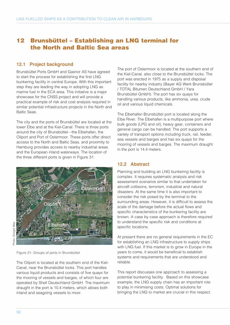
12.1 Project background
Brunsbüttel Ports GmbH and Gasnor AS have agreedto start the process for establishing the first LNGbunkering facility in central Europe. With this importantstep they are leading the way in adopting LNG asmarine fuel in the ECA area. This initiative is a majorshowcase for the CNSS project and will provide apractical example of risk and cost analysis required insimilar potential infrastructure projects in the North andBaltic Seas.
The city and the ports of Brunsbüttel are located at thelower Elbe and at the Kiel-Canal. There is three portsaround the city of Brunsbüttel—the Elbehafen, theOilport and Port of Ostermoor. These ports offer directaccess to the North and Baltic Seas, and proximity toHamburg provides access to nearby industrial areasand the European inland waterways. The location ofthe three different ports is given in Figure 31.
Figure 31: Groups of ports in Brunsbüttel
The Oilport is located at the southern end of the Kiel-Canal, near the Brunsbüttel locks. This port handlesvarious liquid products and consists of five quays forthe mooring of vessels and barges, of which four areoperated by Shell Deutschland GmbH. The maximumdraught in the port is 10.4 meters, which allows bothinland and seagoing vessels to moor.
The port of Ostermoor is located at the southern end ofthe Kiel-Canal, also close to the Brunsbüttel locks. Theport was erected in 1975 as a supply and disposalfacility for nearby industry (Bayer AG Werk Brunsbüttel/ TOTAL Bitumen Deutschland GmbH / YaraBrunsbüttel GmbH). The port has six quays forhandling various products, like ammonia, urea, crudeoil and various liquid chemicals.
The Elbehafen Brunsbüttel port is located along theElbe River. The Elbehafen is a multipurpose port wherebulk goods (LPG and oil), heavy gear, containers andgeneral cargo can be handled. The port supports avariety of transport options including truck, rail, feeder,sea vessels and barges and has six quays for themooring of vessels and barges. The maximum draughtin the port is 14.4 meters.
12.2 Abstract
Planning and building an LNG bunkering facility iscomplex. It requires systematic analysis and riskassessment scenarios similar to that undertaken foraircraft collisions, terrorism, industrial and naturaldisasters. At the same time it is also important toconsider the risk posed by the terminal to thesurrounding areas. However, it is difficult to assess thescale of the damage before the actual flows andspecific characteristics of the bunkering facility areknown. A case by case approach is therefore requiredto understand the specific risk and conditions atspecific locations.
At present there are no general requirements in the ECfor establishing an LNG infrastructure to supply shipswith LNG fuel. If this market is to grow in Europe in theyears to come, it would be beneficial to establishsystems and requirements that are understood andreliable.
This report discusses one approach to assessing apotential bunkering facility. Based on this showcaseexample, the LNG supply chain has an important roleto play in minimising costs. Optimal solutions forbringing the LNG to market are crucial in this respect.
56
LNG FUELLED SHIPS AS A CONTRIBUTION TO CLEAN AIR IN HARBOURS
12 Brunsbüttel – Establishing an LNG terminal for the North and Baltic Sea areas
Ostermoor
Oilport
Elbehafen
Photo: G
oogle Map
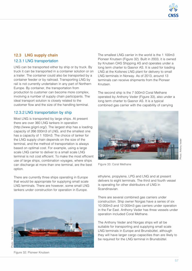
57
12.3 LNG supply chain
12.3.1 LNG transportation
LNG can be transported either by ship or by truck. Bytruck it can be transported in a container solution or ona trailer. The container could also be transported by acontainer feeder or by railroad. Transporting LNG byrail is not currently undertaken in any part of NorthernEurope. By container, the transportation fromproduction to customer can become more complex,involving a number of supply chain participants. Theideal transport solution is closely related to thecustomer flow and the size of the handling terminal.
12.3.2 LNG transportation by ship
Most LNG is transported by large ships. At presentthere are over 360 LNG tankers in operation(http://www.giignl.org/). The largest ship has a loadingcapacity of 266 000m3 of LNG, and the smallest onehas a capacity of 1 100m3. The choice of tanker forthe LNG supply chain depends on the size of theterminal, and the method of transportation is alwaysbased on optimal cost. For example, using a largescale LNG carrier to deliver to a small scale LNGterminal is not cost efficient. To make the most efficientuse of large ships, combination voyages, where shipscan discharge at more than one terminal, are the bestoption.
There are currently three ships operating in Europethat would be appropriate for supplying small scaleLNG terminals. There are however, some small LNGtankers under construction for operation in Europe.
The smallest LNG carrier in the world is the 1 100m3Pioneer Knutsen (Figure 32). Built in 2003, it is ownedby Knutsen OAS Shipping AS and operates under along term charter to Gasnor AS. It is used for loadingLNG at the Kollsnes LNG plant for delivery to smallLNG terminals in Norway. As of 2013, around 13terminals can receive shipments from the PioneerKnutsen.
The second ship is the 7 500m3 Coral Methaneoperated by Anthony Veder (Figure 33), also under along term charter to Gasnor AS. It is a typicalcombined gas carrier with the capability of carrying
ethylene, propylene, LPG and LNG and at presentdelivers to eight terminals. The third and fourth vesselis operating for other distributors of LNG inScandinavian.
There are several combined gas carriers underconstruction. Ship owner Norgas have a series of six10 000m3 and 12 000m3 gas carriers under operationin the Far East. Anthony Veder has three vessels underoperation included Coral Methane.
The Anthony Veder and Norgas ships will all besuitable for transporting and supplying small scaleLNG terminals in Europe and Brunsbüttel, althoughthey will have larger cargo capacities than are likely tobe required for the LNG terminal in Brunsbüttel.
Figure 32: Pioneer Knutsen
Photo: Antony Veder
Photo: Harald Arnøy
Figure 33: Coral Methane
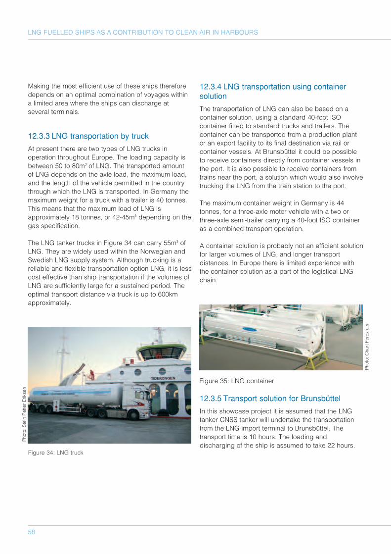
58
LNG FUELLED SHIPS AS A CONTRIBUTION TO CLEAN AIR IN HARBOURS
Making the most efficient use of these ships thereforedepends on an optimal combination of voyages withina limited area where the ships can discharge atseveral terminals.
12.3.3 LNG transportation by truck
At present there are two types of LNG trucks inoperation throughout Europe. The loading capacity isbetween 50 to 80m3 of LNG. The transported amountof LNG depends on the axle load, the maximum load,and the length of the vehicle permitted in the countrythrough which the LNG is transported. In Germany themaximum weight for a truck with a trailer is 40 tonnes.This means that the maximum load of LNG isapproximately 18 tonnes, or 42-45m3 depending on thegas specification.
The LNG tanker trucks in Figure 34 can carry 55m3 ofLNG. They are widely used within the Norwegian andSwedish LNG supply system. Although trucking is areliable and flexible transportation option LNG, it is lesscost effective than ship transportation if the volumes ofLNG are sufficiently large for a sustained period. Theoptimal transport distance via truck is up to 600kmapproximately.
12.3.4 LNG transportation using containersolution
The transportation of LNG can also be based on acontainer solution, using a standard 40-foot ISOcontainer fitted to standard trucks and trailers. Thecontainer can be transported from a production plantor an export facility to its final destination via rail orcontainer vessels. At Brunsbüttel it could be possibleto receive containers directly from container vessels inthe port. It is also possible to receive containers fromtrains near the port, a solution which would also involvetrucking the LNG from the train station to the port.
The maximum container weight in Germany is 44tonnes, for a three-axle motor vehicle with a two orthree-axle semi-trailer carrying a 40-foot ISO containeras a combined transport operation.
A container solution is probably not an efficient solutionfor larger volumes of LNG, and longer transportdistances. In Europe there is limited experience withthe container solution as a part of the logistical LNGchain.
12.3.5 Transport solution for Brunsbüttel
In this showcase project it is assumed that the LNGtanker CNSS tanker will undertake the transportationfrom the LNG import terminal to Brunsbüttel. Thetransport time is 10 hours. The loading anddischarging of the ship is assumed to take 22 hours.
Figure 34: LNG truck
Figure 35: LNG container
Photo: Chart Ferox a.s
Photo: Stein Petter Eriksen

59
12.4 Alternative terminal concepts
Today there are two main types of tanks in use asbunkering terminals—pressurized and atmospherictanks. The atmospherics tanks will be either steel orconcrete tanks.
When planning an LNG supply system, it is veryimportant to consider the type and size of the terminal.The number and frequency of bunkering operation isalso of great importance. At the same time, thelogistical system for supplying the terminal is crucial inoptimizing the whole supply chain.
Several ISO technical committees are developingstandards and specification for LNG installations andequipments. The ISO/TC 67 - Materials, equipment andoffshore structures for petroleum, petrochemical andnatural gas industries, is one such example(www.iso.org). In Europe the ISO standards areimplemented by all European member states as EN-ISO standards. A European standard has also beendeveloped, CEN/TC 282. For further informationplease refer to LNG LESAS Project – Final Report WP3.
12.4.1 Atmospheric tanks
Atmospheric tanks are designed to hold the LNGbelow boiling point and under 0,1 bar pressure.Atmospheric tanks are usually constructed on site, andcannot be moved to other locations unless the tank isstripped down. As a general rule, atmospheric tankstend to be larger than pressurized tanks. To be able tohandle the boil-off from atmospheric tanks, the tankfacility must be connected to local gas grid, or there areliquefaction unit must be installed to keep the gasbelow boiling point. The operating volume of the tanksis usually less than the gross volume of the tanks.Under normal operation the net operating volume isapproximately 90%. The boil-off gas rate is normallyaround 0,2% per day (MAGALOG, 2008)
Atmospheric LNG tanks can be divided into:
• Single containment type• Double containment tank• Full containment tank• Membrane containment tank
The atmospheric tank is constructed from concreteor/and stainless steel.
12.4.1.1 Steel tanks
Steel tanks are constructed on site, and cannot bemoved to other locations unless the tank is strippeddown. Steel tanks are probably most effective in a midscale range (see Figure 36). As the tank cannot handleany pressure, it is important that the boil-off gas isused locally.
12.4.1.2 Concrete tanks
Concrete tanks are usually built for large scaleoperations. One of the smallest concrete LNG tankswas built in Sweden (see Figure 37). The capacity ofthe terminal is 20 000m3.
So far there is just one concrete tank used for LNGbunkering anywhere in the world. This tank is located
Figure 36: Steel tanks at Kollsnes
Figure 37: AGA LNG terminal Nynäshamn, with Coral Methane
Photo: AGA AB
Photo: Gasnor AS
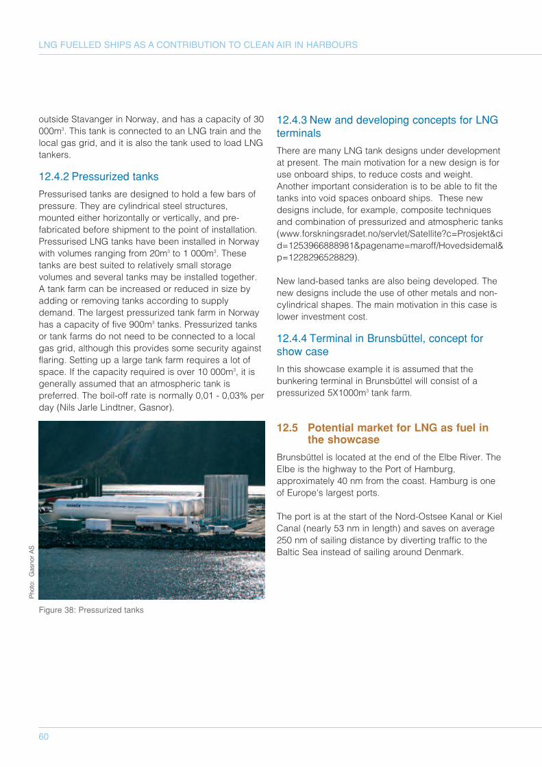
60
LNG FUELLED SHIPS AS A CONTRIBUTION TO CLEAN AIR IN HARBOURS
outside Stavanger in Norway, and has a capacity of 30000m3. This tank is connected to an LNG train and thelocal gas grid, and it is also the tank used to load LNGtankers.
12.4.2 Pressurized tanks
Pressurised tanks are designed to hold a few bars ofpressure. They are cylindrical steel structures,mounted either horizontally or vertically, and pre-fabricated before shipment to the point of installation.Pressurised LNG tanks have been installed in Norwaywith volumes ranging from 20m3 to 1 000m3. Thesetanks are best suited to relatively small storagevolumes and several tanks may be installed together.A tank farm can be increased or reduced in size byadding or removing tanks according to supplydemand. The largest pressurized tank farm in Norwayhas a capacity of five 900m3 tanks. Pressurized tanksor tank farms do not need to be connected to a localgas grid, although this provides some security againstflaring. Setting up a large tank farm requires a lot ofspace. If the capacity required is over 10 000m3, it isgenerally assumed that an atmospheric tank ispreferred. The boil-off rate is normally 0,01 - 0,03% perday (Nils Jarle Lindtner, Gasnor).
12.4.3 New and developing concepts for LNGterminals
There are many LNG tank designs under developmentat present. The main motivation for a new design is foruse onboard ships, to reduce costs and weight.Another important consideration is to be able to fit thetanks into void spaces onboard ships. These newdesigns include, for example, composite techniquesand combination of pressurized and atmospheric tanks(www.forskningsradet.no/servlet/Satellite?c=Prosjekt&cid=1253966888981&pagename=maroff/Hovedsidemal&p=1228296528829).
New land-based tanks are also being developed. Thenew designs include the use of other metals and non-cylindrical shapes. The main motivation in this case islower investment cost.
12.4.4 Terminal in Brunsbüttel, concept forshow case
In this showcase example it is assumed that thebunkering terminal in Brunsbüttel will consist of apressurized 5X1000m3 tank farm.
12.5 Potential market for LNG as fuel inthe showcase
Brunsbüttel is located at the end of the Elbe River. TheElbe is the highway to the Port of Hamburg,approximately 40 nm from the coast. Hamburg is oneof Europe's largest ports.
The port is at the start of the Nord-Ostsee Kanal or KielCanal (nearly 53 nm in length) and saves on average250 nm of sailing distance by diverting traffic to theBaltic Sea instead of sailing around Denmark.
Figure 38: Pressurized tanks
Photo: Gasnor AS
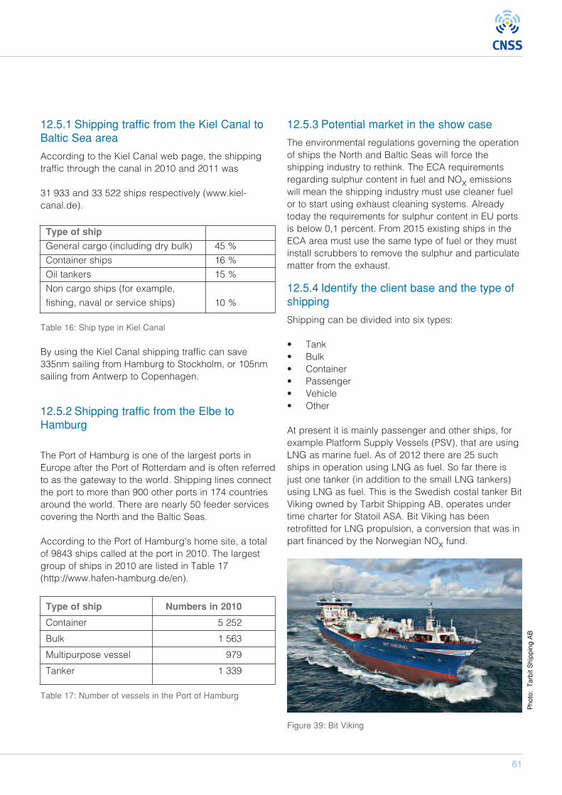
61
12.5.1 Shipping traffic from the Kiel Canal toBaltic Sea area
According to the Kiel Canal web page, the shippingtraffic through the canal in 2010 and 2011 was
31 933 and 33 522 ships respectively (www.kiel-canal.de).
Type of ship
General cargo (including dry bulk) 45 %
Container ships 16 %
Oil tankers 15 %
Non cargo ships (for example,
fishing, naval or service ships) 10 %
Table 16: Ship type in Kiel Canal
By using the Kiel Canal shipping traffic can save335nm sailing from Hamburg to Stockholm, or 105nmsailing from Antwerp to Copenhagen.
12.5.2 Shipping traffic from the Elbe toHamburg
The Port of Hamburg is one of the largest ports inEurope after the Port of Rotterdam and is often referredto as the gateway to the world. Shipping lines connectthe port to more than 900 other ports in 174 countriesaround the world. There are nearly 50 feeder servicescovering the North and the Baltic Seas.
According to the Port of Hamburg’s home site, a totalof 9843 ships called at the port in 2010. The largestgroup of ships in 2010 are listed in Table 17(http://www.hafen-hamburg.de/en).
Type of ship Numbers in 2010
Container 5 252
Bulk 1 563
Multipurpose vessel 979
Tanker 1 339
Table 17: Number of vessels in the Port of Hamburg
12.5.3 Potential market in the show case
The environmental regulations governing the operationof ships the North and Baltic Seas will force theshipping industry to rethink. The ECA requirementsregarding sulphur content in fuel and NOx emissionswill mean the shipping industry must use cleaner fuelor to start using exhaust cleaning systems. Alreadytoday the requirements for sulphur content in EU portsis below 0,1 percent. From 2015 existing ships in theECA area must use the same type of fuel or they mustinstall scrubbers to remove the sulphur and particulatematter from the exhaust.
12.5.4 Identify the client base and the type ofshipping
Shipping can be divided into six types:
• Tank• Bulk• Container• Passenger• Vehicle• Other
At present it is mainly passenger and other ships, forexample Platform Supply Vessels (PSV), that are usingLNG as marine fuel. As of 2012 there are 25 suchships in operation using LNG as fuel. So far there isjust one tanker (in addition to the small LNG tankers)using LNG as fuel. This is the Swedish costal tanker BitViking owned by Tarbit Shipping AB, operates undertime charter for Statoil ASA. Bit Viking has beenretrofitted for LNG propulsion, a conversion that was inpart financed by the Norwegian NOx fund.
Figure 39: Bit Viking
Photo: Tarbit Shipping AB
Photo: Tarbit Shipping AB
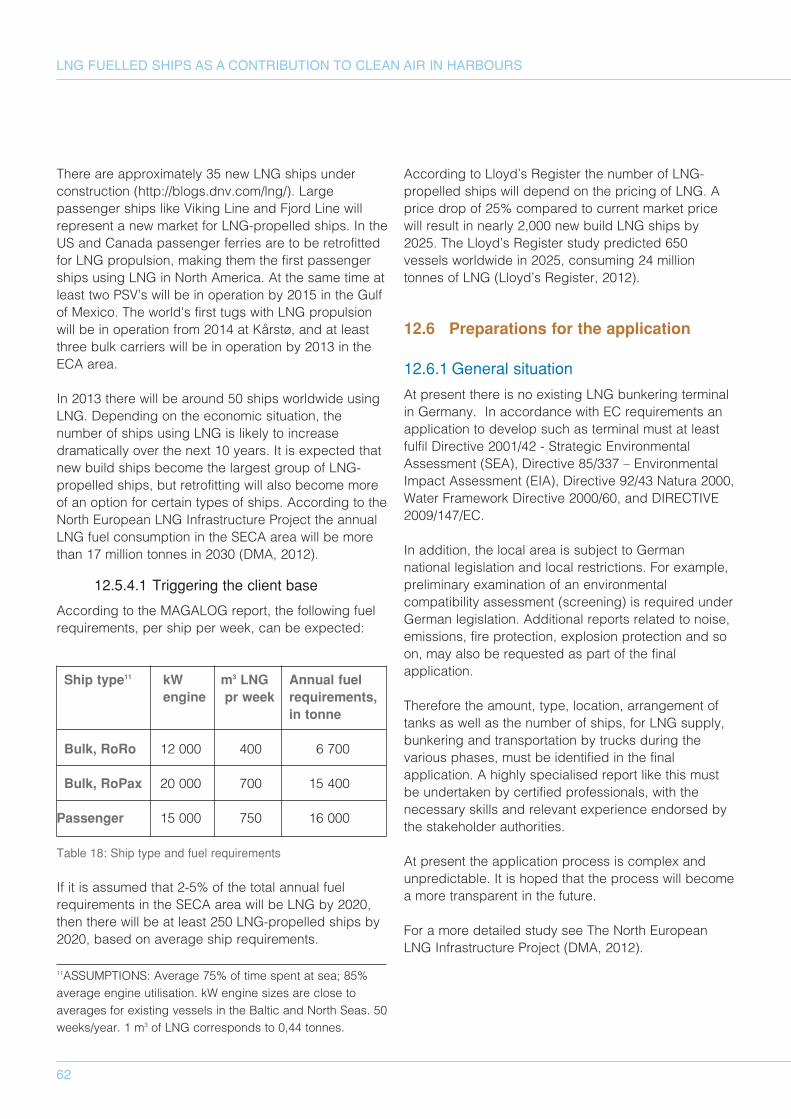
62
LNG FUELLED SHIPS AS A CONTRIBUTION TO CLEAN AIR IN HARBOURS
There are approximately 35 new LNG ships underconstruction (http://blogs.dnv.com/lng/). Largepassenger ships like Viking Line and Fjord Line willrepresent a new market for LNG-propelled ships. In theUS and Canada passenger ferries are to be retrofittedfor LNG propulsion, making them the first passengerships using LNG in North America. At the same time atleast two PSV’s will be in operation by 2015 in the Gulfof Mexico. The world's first tugs with LNG propulsionwill be in operation from 2014 at Kårstø, and at leastthree bulk carriers will be in operation by 2013 in theECA area.
In 2013 there will be around 50 ships worldwide usingLNG. Depending on the economic situation, thenumber of ships using LNG is likely to increasedramatically over the next 10 years. It is expected thatnew build ships become the largest group of LNG-propelled ships, but retrofitting will also become moreof an option for certain types of ships. According to theNorth European LNG Infrastructure Project the annualLNG fuel consumption in the SECA area will be morethan 17 million tonnes in 2030 (DMA, 2012).
12.5.4.1 Triggering the client base
According to the MAGALOG report, the following fuelrequirements, per ship per week, can be expected:
Ship type11 kW m3 LNG Annual fuel engine pr week requirements,
in tonne
Bulk, RoRo 12 000 400 6 700
Bulk, RoPax 20 000 700 15 400
Passenger 15 000 750 16 000
Table 18: Ship type and fuel requirements
If it is assumed that 2-5% of the total annual fuelrequirements in the SECA area will be LNG by 2020,then there will be at least 250 LNG-propelled ships by2020, based on average ship requirements.
According to Lloyd’s Register the number of LNG-propelled ships will depend on the pricing of LNG. Aprice drop of 25% compared to current market pricewill result in nearly 2,000 new build LNG ships by2025. The Lloyd’s Register study predicted 650vessels worldwide in 2025, consuming 24 milliontonnes of LNG (Lloyd’s Register, 2012).
12.6 Preparations for the application
12.6.1 General situation
At present there is no existing LNG bunkering terminalin Germany. In accordance with EC requirements anapplication to develop such as terminal must at leastfulfil Directive 2001/42 - Strategic EnvironmentalAssessment (SEA), Directive 85/337 – EnvironmentalImpact Assessment (EIA), Directive 92/43 Natura 2000,Water Framework Directive 2000/60, and DIRECTIVE2009/147/EC.
In addition, the local area is subject to Germannational legislation and local restrictions. For example,preliminary examination of an environmentalcompatibility assessment (screening) is required underGerman legislation. Additional reports related to noise,emissions, fire protection, explosion protection and soon, may also be requested as part of the finalapplication.
Therefore the amount, type, location, arrangement oftanks as well as the number of ships, for LNG supply,bunkering and transportation by trucks during thevarious phases, must be identified in the finalapplication. A highly specialised report like this mustbe undertaken by certified professionals, with thenecessary skills and relevant experience endorsed bythe stakeholder authorities.
At present the application process is complex andunpredictable. It is hoped that the process will becomea more transparent in the future.
For a more detailed study see The North EuropeanLNG Infrastructure Project (DMA, 2012).
11ASSUMPTIONS: Average 75% of time spent at sea; 85%average engine utilisation. kW engine sizes are close toaverages for existing vessels in the Baltic and North Seas. 50weeks/year. 1 m3 of LNG corresponds to 0,44 tonnes.
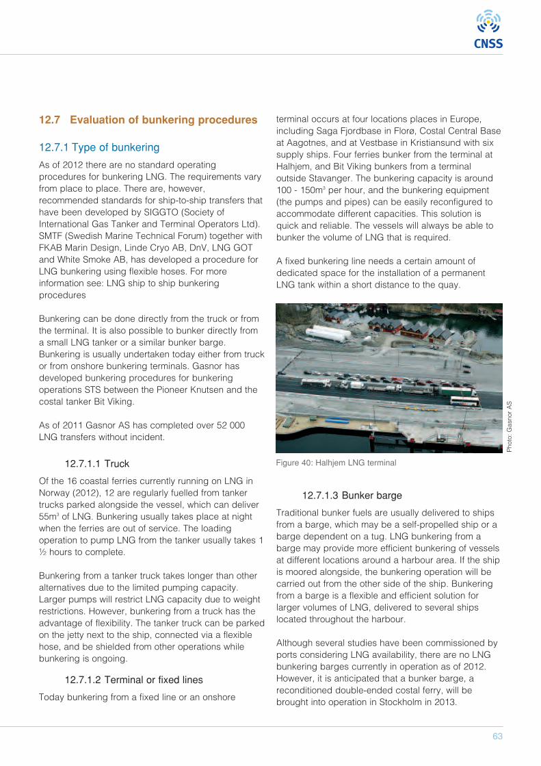
63
12.7 Evaluation of bunkering procedures
12.7.1 Type of bunkering
As of 2012 there are no standard operatingprocedures for bunkering LNG. The requirements varyfrom place to place. There are, however,recommended standards for ship-to-ship transfers thathave been developed by SIGGTO (Society ofInternational Gas Tanker and Terminal Operators Ltd).SMTF (Swedish Marine Technical Forum) together withFKAB Marin Design, Linde Cryo AB, DnV, LNG GOTand White Smoke AB, has developed a procedure forLNG bunkering using flexible hoses. For moreinformation see: LNG ship to ship bunkeringprocedures
Bunkering can be done directly from the truck or fromthe terminal. It is also possible to bunker directly froma small LNG tanker or a similar bunker barge.Bunkering is usually undertaken today either from truckor from onshore bunkering terminals. Gasnor hasdeveloped bunkering procedures for bunkeringoperations STS between the Pioneer Knutsen and thecostal tanker Bit Viking.
As of 2011 Gasnor AS has completed over 52 000LNG transfers without incident.
12.7.1.1 Truck
Of the 16 coastal ferries currently running on LNG inNorway (2012), 12 are regularly fuelled from tankertrucks parked alongside the vessel, which can deliver55m3 of LNG. Bunkering usually takes place at nightwhen the ferries are out of service. The loadingoperation to pump LNG from the tanker usually takes 1½ hours to complete.
Bunkering from a tanker truck takes longer than otheralternatives due to the limited pumping capacity.Larger pumps will restrict LNG capacity due to weightrestrictions. However, bunkering from a truck has theadvantage of flexibility. The tanker truck can be parkedon the jetty next to the ship, connected via a flexiblehose, and be shielded from other operations whilebunkering is ongoing.
12.7.1.2 Terminal or fixed lines
Today bunkering from a fixed line or an onshore
terminal occurs at four locations places in Europe,including Saga Fjordbase in Florø, Costal Central Baseat Aagotnes, and at Vestbase in Kristiansund with sixsupply ships. Four ferries bunker from the terminal atHalhjem, and Bit Viking bunkers from a terminaloutside Stavanger. The bunkering capacity is around100 - 150m3 per hour, and the bunkering equipment(the pumps and pipes) can be easily reconfigured toaccommodate different capacities. This solution isquick and reliable. The vessels will always be able tobunker the volume of LNG that is required.
A fixed bunkering line needs a certain amount ofdedicated space for the installation of a permanentLNG tank within a short distance to the quay.
12.7.1.3 Bunker barge
Traditional bunker fuels are usually delivered to shipsfrom a barge, which may be a self-propelled ship or abarge dependent on a tug. LNG bunkering from abarge may provide more efficient bunkering of vesselsat different locations around a harbour area. If the shipis moored alongside, the bunkering operation will becarried out from the other side of the ship. Bunkeringfrom a barge is a flexible and efficient solution forlarger volumes of LNG, delivered to several shipslocated throughout the harbour.
Although several studies have been commissioned byports considering LNG availability, there are no LNGbunkering barges currently in operation as of 2012.However, it is anticipated that a bunker barge, areconditioned double-ended costal ferry, will bebrought into operation in Stockholm in 2013.
Figure 40: Halhjem LNG terminal
Photo: G
asnor AS
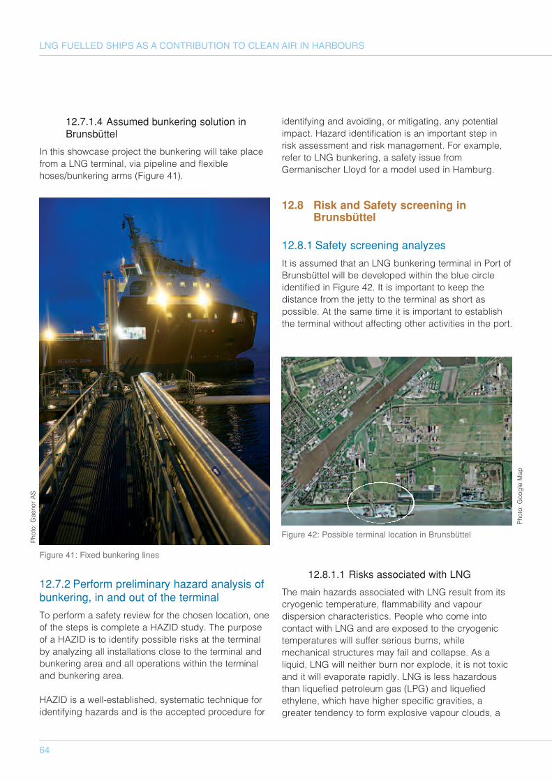
64
LNG FUELLED SHIPS AS A CONTRIBUTION TO CLEAN AIR IN HARBOURS
12.7.1.4 Assumed bunkering solution inBrunsbüttel
In this showcase project the bunkering will take placefrom a LNG terminal, via pipeline and flexiblehoses/bunkering arms (Figure 41).
12.7.2 Perform preliminary hazard analysis ofbunkering, in and out of the terminal
To perform a safety review for the chosen location, oneof the steps is complete a HAZID study. The purposeof a HAZID is to identify possible risks at the terminalby analyzing all installations close to the terminal andbunkering area and all operations within the terminaland bunkering area.
HAZID is a well-established, systematic technique foridentifying hazards and is the accepted procedure for
identifying and avoiding, or mitigating, any potentialimpact. Hazard identification is an important step inrisk assessment and risk management. For example,refer to LNG bunkering, a safety issue fromGermanischer Lloyd for a model used in Hamburg.
12.8 Risk and Safety screening inBrunsbüttel
12.8.1 Safety screening analyzes
It is assumed that an LNG bunkering terminal in Port ofBrunsbüttel will be developed within the blue circleidentified in Figure 42. It is important to keep thedistance from the jetty to the terminal as short aspossible. At the same time it is important to establishthe terminal without affecting other activities in the port.
12.8.1.1 Risks associated with LNG
The main hazards associated with LNG result from itscryogenic temperature, flammability and vapourdispersion characteristics. People who come intocontact with LNG and are exposed to the cryogenictemperatures will suffer serious burns, whilemechanical structures may fail and collapse. As aliquid, LNG will neither burn nor explode, it is not toxicand it will evaporate rapidly. LNG is less hazardousthan liquefied petroleum gas (LPG) and liquefiedethylene, which have higher specific gravities, agreater tendency to form explosive vapour clouds, a
Figure 41: Fixed bunkering lines
Figure 42: Possible terminal location in Brunsbüttel
Photo: G
asnor AS
Photo: G
oogle Map
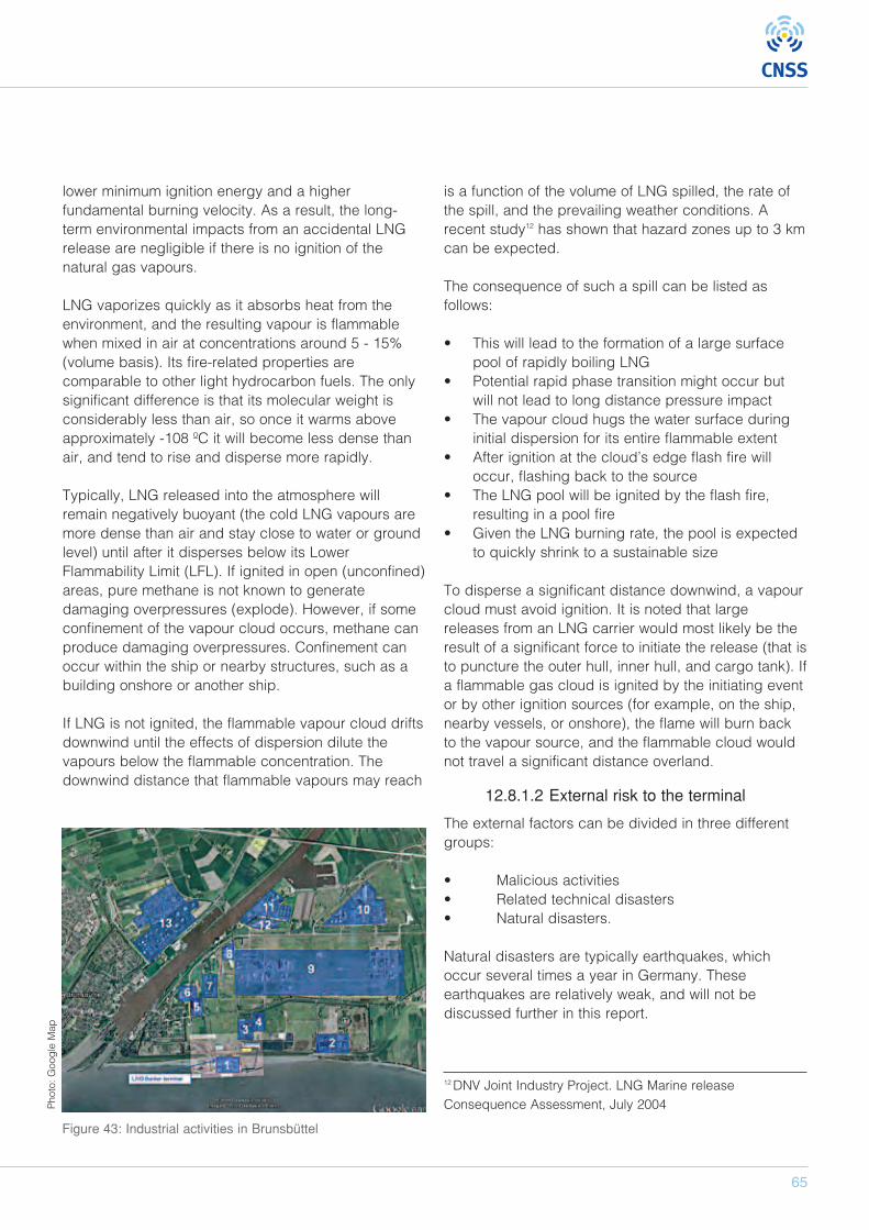
65
lower minimum ignition energy and a higherfundamental burning velocity. As a result, the long-term environmental impacts from an accidental LNGrelease are negligible if there is no ignition of thenatural gas vapours.
LNG vaporizes quickly as it absorbs heat from theenvironment, and the resulting vapour is flammablewhen mixed in air at concentrations around 5 - 15%(volume basis). Its fire-related properties arecomparable to other light hydrocarbon fuels. The onlysignificant difference is that its molecular weight isconsiderably less than air, so once it warms aboveapproximately -108 ºC it will become less dense thanair, and tend to rise and disperse more rapidly.
Typically, LNG released into the atmosphere willremain negatively buoyant (the cold LNG vapours aremore dense than air and stay close to water or groundlevel) until after it disperses below its LowerFlammability Limit (LFL). If ignited in open (unconfined)areas, pure methane is not known to generatedamaging overpressures (explode). However, if someconfinement of the vapour cloud occurs, methane canproduce damaging overpressures. Confinement canoccur within the ship or nearby structures, such as abuilding onshore or another ship.
If LNG is not ignited, the flammable vapour cloud driftsdownwind until the effects of dispersion dilute thevapours below the flammable concentration. Thedownwind distance that flammable vapours may reach
is a function of the volume of LNG spilled, the rate ofthe spill, and the prevailing weather conditions. Arecent study12 has shown that hazard zones up to 3 kmcan be expected.
The consequence of such a spill can be listed asfollows:
• This will lead to the formation of a large surfacepool of rapidly boiling LNG
• Potential rapid phase transition might occur butwill not lead to long distance pressure impact
• The vapour cloud hugs the water surface duringinitial dispersion for its entire flammable extent
• After ignition at the cloud’s edge flash fire willoccur, flashing back to the source
• The LNG pool will be ignited by the flash fire,resulting in a pool fire
• Given the LNG burning rate, the pool is expectedto quickly shrink to a sustainable size
To disperse a significant distance downwind, a vapourcloud must avoid ignition. It is noted that largereleases from an LNG carrier would most likely be theresult of a significant force to initiate the release (that isto puncture the outer hull, inner hull, and cargo tank). Ifa flammable gas cloud is ignited by the initiating eventor by other ignition sources (for example, on the ship,nearby vessels, or onshore), the flame will burn backto the vapour source, and the flammable cloud wouldnot travel a significant distance overland.
12.8.1.2 External risk to the terminal
The external factors can be divided in three differentgroups:
• Malicious activities • Related technical disasters • Natural disasters.
Natural disasters are typically earthquakes, whichoccur several times a year in Germany. Theseearthquakes are relatively weak, and will not bediscussed further in this report.
Figure 43: Industrial activities in Brunsbüttel
12 DNV Joint Industry Project. LNG Marine releaseConsequence Assessment, July 2004 P
hoto: G
oogle Map
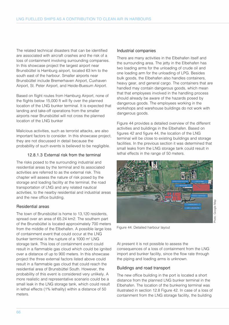
66
LNG FUELLED SHIPS AS A CONTRIBUTION TO CLEAN AIR IN HARBOURS
The related technical disasters that can be identifiedare associated with aircraft crashes and the risk of aloss of containment involving surrounding companies.In this showcase project the largest airport nearBrunsbüttel is Hamburg airport, located 63 km to thesouth east of the harbour. Smaller airports nearBrunsbüttel include Bremerhaven Airport, CuxhavenAirport, St. Peter Airport, and Heide-Buesum Airport.
Based on flight routes from Hamburg Airport, none ofthe flights below 15,000 ft will fly over the plannedlocation of the LNG bunker terminal. It is expected thatlanding and take-off operations from the smallerairports near Brunsbüttel will not cross the plannedlocation of the LNG bunker
Malicious activities, such as terrorist attacks, are alsoimportant factors to consider. In this showcase project,they are not discussed in detail because theprobability of such events is believed to be negligible.
12.8.1.3 External risk from the terminal
The risks posed to the surrounding industrial andresidential areas by the terminal and its associatedactivities are referred to as the external risk. Thischapter will assess the nature of risk posed by thestorage and loading facility at the terminal, the roadtransportation of LNG and any related nauticalactivities, to the nearby residential and industrial areasand the new office building.
Residential areas
The town of Brunsbüttel is home to 13,120 residents,spread over an area of 65.24 km2. The southern partof the Brunsbüttel is located approximately 700 metersfrom the middle of the Elbehafen. A possible large lossof containment event that could occur at the LNGbunker terminal is the rupture of a 1000 m3 LNGstorage tank. This loss of containment event couldresult in a flammable gas cloud which could be ignitedover a distance of up to 900 meters. In this showcaseproject the three external factors listed above couldresult in a flammable gas cloud that could reach theresidential area of Brunsbüttel South. However, theprobability of this event is considered very unlikely. Amore realistic and representative scenario could be asmall leak in the LNG storage tank, which could resultin lethal effects (1% lethality) within a distance of 50meters.
Industrial companies
There are many activities in the Elbehafen itself andthe surrounding area. The jetty in the Elbehafen hastwo loading arms for the unloading of crude oil andone loading arm for the unloading of LPG. Besidesbulk goods, the Elbehafen also handles containers,heavy gear, and general cargo. The containers that arehandled may contain dangerous goods, which meanthat that employees involved in the handling processshould already be aware of the hazards posed bydangerous goods. The employees working in theworkshops and warehouse buildings do not work withdangerous goods.
Figure 44 provides a detailed overview of the differentactivities and buildings in the Elbehafen. Based onfigures 42 and figure 44, the location of the LNGterminal will be close to existing buildings and storagefacilities. In the previous section it was determined thatsmall leaks from the LNG storage tank could result inlethal effects in the range of 50 meters.
At present it is not possible to assess theconsequences of a loss of containment from the LNGimport and bunker facility, since the flow rate throughthe piping and loading arms is unknown.
Buildings and road transport
The new office building in the port is located a shortdistance from the planned LNG bunker terminal in theElbehafen. The location of the bunkering terminal wasillustrated in section 12.8 Figure 42. In case of a loss ofcontainment from the LNG storage facility, the building
Figure 44: Detailed harbour layout
Photo: G
oogle Map
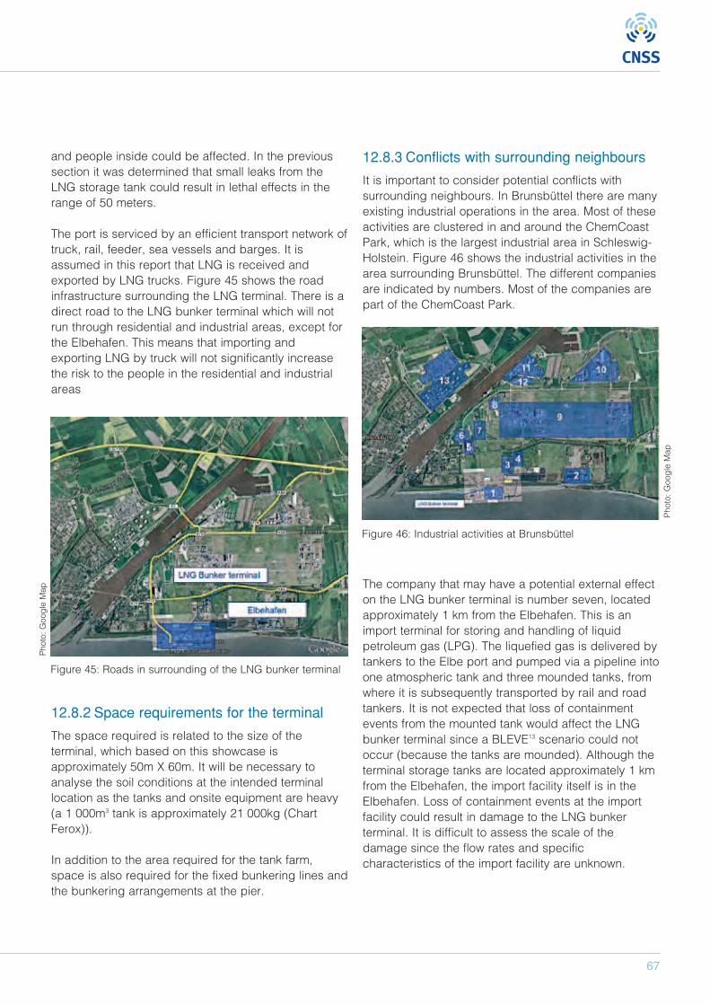
67
and people inside could be affected. In the previoussection it was determined that small leaks from theLNG storage tank could result in lethal effects in therange of 50 meters.
The port is serviced by an efficient transport network oftruck, rail, feeder, sea vessels and barges. It isassumed in this report that LNG is received andexported by LNG trucks. Figure 45 shows the roadinfrastructure surrounding the LNG terminal. There is adirect road to the LNG bunker terminal which will notrun through residential and industrial areas, except forthe Elbehafen. This means that importing andexporting LNG by truck will not significantly increasethe risk to the people in the residential and industrialareas
12.8.2 Space requirements for the terminal
The space required is related to the size of theterminal, which based on this showcase isapproximately 50m X 60m. It will be necessary toanalyse the soil conditions at the intended terminallocation as the tanks and onsite equipment are heavy(a 1 000m3 tank is approximately 21 000kg (ChartFerox)).
In addition to the area required for the tank farm,space is also required for the fixed bunkering lines andthe bunkering arrangements at the pier.
12.8.3 Conflicts with surrounding neighbours
It is important to consider potential conflicts withsurrounding neighbours. In Brunsbüttel there are manyexisting industrial operations in the area. Most of theseactivities are clustered in and around the ChemCoastPark, which is the largest industrial area in Schleswig-Holstein. Figure 46 shows the industrial activities in thearea surrounding Brunsbüttel. The different companiesare indicated by numbers. Most of the companies arepart of the ChemCoast Park.
The company that may have a potential external effecton the LNG bunker terminal is number seven, locatedapproximately 1 km from the Elbehafen. This is animport terminal for storing and handling of liquidpetroleum gas (LPG). The liquefied gas is delivered bytankers to the Elbe port and pumped via a pipeline intoone atmospheric tank and three mounded tanks, fromwhere it is subsequently transported by rail and roadtankers. It is not expected that loss of containmentevents from the mounted tank would affect the LNGbunker terminal since a BLEVE13 scenario could notoccur (because the tanks are mounded). Although theterminal storage tanks are located approximately 1 kmfrom the Elbehafen, the import facility itself is in theElbehafen. Loss of containment events at the importfacility could result in damage to the LNG bunkerterminal. It is difficult to assess the scale of thedamage since the flow rates and specificcharacteristics of the import facility are unknown.
Figure 46: Industrial activities at Brunsbüttel
Figure 45: Roads in surrounding of the LNG bunker terminal
Photo: G
oogle Map
Photo: G
oogle Map

68
LNG FUELLED SHIPS AS A CONTRIBUTION TO CLEAN AIR IN HARBOURS
12.8.4 Terminal layout
Figure 17 provides an illustration of a terminalconsisting of 3 x 1000m3 pressurised tanks. Note, thisexample does not include the regasification unit thatwould be required if the terminal was part of the localgas distribution system. A 3 x 1000m3 terminal can befilled with approximately 1,200 tonnes of LNG, or 18GWh. The size of such an installation will beapproximately 50m x 60m and this standard layoutcould be adapted to local conditions. The terminal isconfigured with all connections and valves at one endand, for safety purposes, an accumulation pool is also
provided at that end of the terminal. In the unlikelyevent of a leakage of LNG, the liquid would becollected in this pool. There will be safety and EXzones around the accumulation pool. This area will bewithin an enclosure and there will be restrictions on allactivities that may involve ignition sources.
An insulated LNG pipeline, probably submerged in aduct, connects the terminal with the ship connectionpoint at the jetty. There is also a safety zone aroundthe connection point, and an evacuation zone aroundthe terminal, the size of which would be based on therisk assessment that had been carried out. Thisevacuation zone is prepared for emergencies in theevent of an incident at the terminal.
Figure 47 provides an example of a 3 x 1 000m3
terminal with truck filling facilities.
12.9 Pilot study
12.9.1 Foundation for investment decision inthe show case
In this showcase the basic set-up for the LNG terminalwill be as described in the following sections.
131 A boiling liquid expanding vapor explosion (BLEVE) is anexplosion caused by the rupture of a vessel containing apressurized liquid above its boiling point. If a vessel partlyfilled with liquid with vapor above filling the remainder of thecontainer, is ruptured—for example, due to corrosion, orfailure under pressure—the vapor portion may rapidly leak,lowering the pressure inside the container. This sudden dropin pressure inside the container causes violent boiling of theliquid, which rapidly liberates large amounts of vapor. Thepressure of this vapor can be extremely high, causing asignificant wave of overpressure (an explosion) which maycompletely destroy the storage vessel and project fragmentsover the surrounding area.
Figure 47: Terminal layout
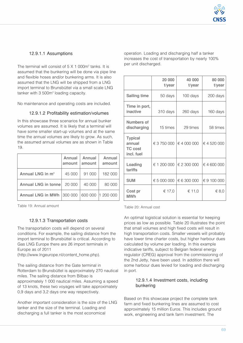
69
12.9.1.1 Assumptions
The terminal will consist of 5 X 1 000m3 tanks. It isassumed that the bunkering will be done via pipe lineand flexible hoses and/or bunkering arms. It is alsoassumed that the LNG will be shipped from a LNGimport terminal to Brunsbüttel via a small scale LNGtanker with 3 500m3 loading capacity.
No maintenance and operating costs are included.
12.9.1.2 Profitability estimation/volumes
In this showcase three scenarios for annual bunkervolumes are assumed. It is likely that a terminal willhave some smaller start-up volumes and at the sametime the annual volumes are likely to grow. As such,the assumed annual volumes are as shown in Table19.
Annual Annual Annualamount amount amount
Annual LNG in m3 45 000 91 000 182 000
Annual LNG in tonne 20 000 40 000 80 000
Annual LNG in MWh 300 000 600 000 1 200 000
Table 19: Annual amount
12.9.1.3 Transportation costs
The transportation costs will depend on severalconditions. For example, the sailing distance from theimport terminal to Brunsbüttel is critical. According toGas LNG Europe there are 26 import terminals inEurope as of 2011(http://www.lngeurope.nl/content_home.php).
The sailing distance from the Gate terminal inRotterdam to Brunsbüttel is approximately 270 nauticalmiles. The sailing distance from Bilbao isapproximately 1 000 nautical miles. Assuming a speedof 13 knots, these two voyages will take approximately0,9 days and 3,2 days one way respectively.
Another important consideration is the size of the LNGtanker and the size of the terminal. Loading anddischarging a full tanker is the most economical
operation. Loading and discharging half a tankerincreases the cost of transportation by nearly 100%per unit discharged.
20 000 40 000 80 000t/year t/year t/year
Sailing time 50 days 100 days 200 days
Time in port,inactive 310 days 260 days 160 days
Numbers of discharging 15 times 29 times 58 times
Typical annual € 3 750 000 € 4 000 000 € 4 520 000TC cost incl. fuel
Loading € 1 200 000 € 2 300 000 € 4 600 000tariffs
SUM € 5 000 000 € 6 300 000 € 9 100 000
Cost pr € 17,0 € 11,0 € 8,0MWh
Table 20: Annual cost
An optimal logistical solution is essential for keepingprices as low as possible. Table 20 illustrates the pointthat small volumes and high fixed costs will result inhigh transportation costs. Smaller vessels will probablyhave lower time charter costs, but higher harbour duescalculated by volume per loading. In this exampleindicative tariffs, subject to Belgian federal energyregulator (CREG) approval from the commissioning ofthe 2nd Jetty, have been used. In addition there willsome harbour dues levied for loading and dischargingin port.
12.9.1.4 Investment costs, includingbunkering
Based on this showcase project the complete tankfarm and fixed bunkering lines are assumed to costapproximately 15 million Euros. This includes groundwork, engineering and tank farm investment. The
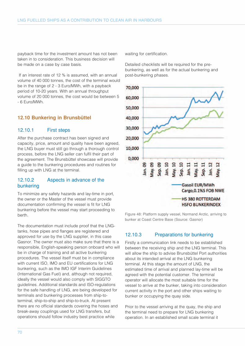
70
LNG FUELLED SHIPS AS A CONTRIBUTION TO CLEAN AIR IN HARBOURS
payback time for the investment amount has not beentaken in to consideration. This business decision willbe made on a case by case basis.
If an interest rate of 12 % is assumed, with an annualvolume of 40 000 tonnes, the cost of the terminal wouldbe in the range of 2 - 3 Euro/MWh, with a paybackperiod of 10-20 years. With an annual throughputvolume of 20 000 tonnes, the cost would be between 5- 6 Euro/MWh.
12.10 Bunkering in Brunsbüttel
12.10.1 First steps
After the purchase contract has been signed andcapacity, price, amount and quality have been agreed,the LNG buyer must still go through a thorough controlprocess, before the LNG seller can fulfil their part ofthe agreement. The Brunsbüttel showcase will providea guide to the bunkering procedures and routines forfilling up with LNG at the terminal.
12.10.2 Aspects in advance of thebunkering
To minimize any safety hazards and lay-time in port,the owner or the Master of the vessel must providedocumentation confirming the vessel is fit for LNGbunkering before the vessel may start proceeding toberth.
The documentation must include proof that the LNG-tanks, hose pipes and flanges are registered andapproved for use by the LNG supplier, in this caseGasnor. The owner must also make sure that there is aresponsible, English-speaking person onboard who willbe in charge of training and all active bunkeringprocedures. The vessel itself must be in compliancewith current ISO, IMO and EU certifications for LNGbunkering, such as the IMO IGF Interim Guidelines(International Gas Fuel) and, although not required,ideally the vessel would also comply with SIGGTOguidelines. Additional standards and ISO-regulationsfor the safe handling of LNG, are being developed forterminals and bunkering processes from ship-to-terminal, ship-to-ship and ship-to-truck. At presentthere are no official standards covering the hoses andbreak-away couplings used for LNG transfers, butoperations should follow industry best practice while
waiting for certification.
Detailed checklists will be required for the pre-bunkering, as well as for the actual bunkering andpost-bunkering phases.
12.10.3 Preparations for bunkering
Firstly a communication link needs to be establishedbetween the receiving ship and the LNG terminal. Thiswill allow the ship to advise Brunsbüttel Port authoritiesabout its intended arrival at the LNG bunkeringterminal. At this stage the amount of LNG, theestimated time of arrival and planned lay-time will beagreed with the potential customer. The terminaloperator will allocate the most suitable time for thevessel to arrive at the bunker, taking into considerationcurrent activity in the port and other ships waiting tobunker or occupying the quay side.
Prior to the vessel arriving at the quay, the ship andthe terminal need to prepare for LNG bunkeringoperation. In an established small scale terminal it
Figure 48: Platform supply vessel, Normand Arctic, arriving tobunker at Coast Centre Base (Source: Gasnor)

71
takes a relatively short time to prepare the tanks, pipesand hoses for bunkering, usually in the region of 15minutes. If this is completed in advance the totalbunkering stay should not exceed 2,5 hours. Thatincludes half an hour mooring and coupling, and halfan hour of decoupling and release once the bunkeringis complete. The duration of the actual bunkering part,that is the flow of LNG from the terminal to the ship,would depend on the volume per time unit that thevessel is able to receive—assuming a pump of500m3/h this should take roughly two hours.
12.10.4 Responsibilities
Although the Master is responsible for all LNGbunkering operations, he may delegate the task to acertified, English-speaking member of staff who hasreceived the necessary in-depth training in thehandling of LNG. The demarcation line for bunkeringresponsibilities lies at the flange. The Master isresponsible for everything shipside of the flange, andthe port captain or the bunker facilitator, in this caseGasnor, is responsible for the bunkering procedures
from the hose to the coupling on the vessel. To ensurea safe operation, it is essential that both ship andterminal crew follow the strict routines and checklists,as described above. This is especially important forthe first bunkering operation, when the procedures forfuture bunkering operations are established.
12.10.5 First bunkering operation
The first time a vessel docks for bunkering, theterminal operators must check permits anddocumentation regarding the tanks and the carriage ofcryogenic liquids. They must also check the routinesput in place for carrying out checklists andpreparations during subsequent bunkering operations.The Master is also responsible for making sure thevessel is ready to bunker LNG, in the same way thatthe terminal operators are responsible for preparingthe bunker arm (see Figure 49) or the hoses that willbe used for the bunkering process. Checklists must besigned and passed to the port captain beforebunkering can commence and after bunkering hasbeen completed. Checklists must be in English and
Figure 49: Example of an LNG bunkering
Photo: G
ermanischer Lloyds/CNSS
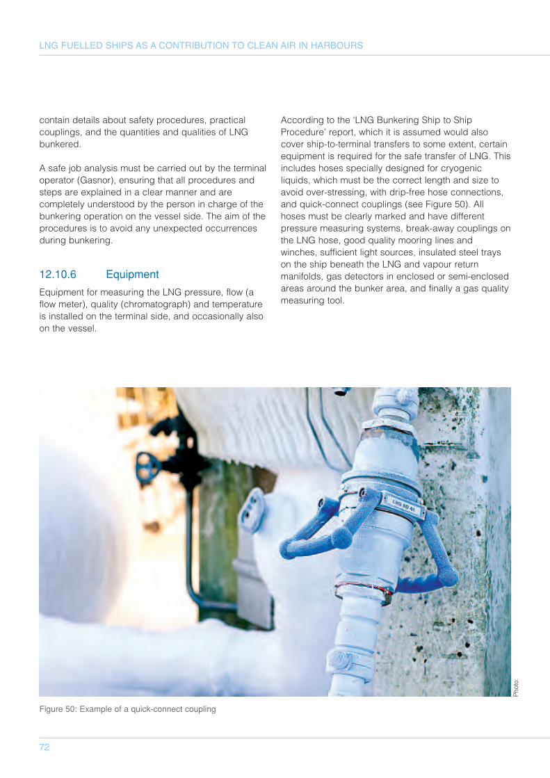
72
LNG FUELLED SHIPS AS A CONTRIBUTION TO CLEAN AIR IN HARBOURS
contain details about safety procedures, practicalcouplings, and the quantities and qualities of LNGbunkered.
A safe job analysis must be carried out by the terminaloperator (Gasnor), ensuring that all procedures andsteps are explained in a clear manner and arecompletely understood by the person in charge of thebunkering operation on the vessel side. The aim of theprocedures is to avoid any unexpected occurrencesduring bunkering.
12.10.6 Equipment
Equipment for measuring the LNG pressure, flow (aflow meter), quality (chromatograph) and temperatureis installed on the terminal side, and occasionally alsoon the vessel.
According to the ‘LNG Bunkering Ship to ShipProcedure’ report, which it is assumed would alsocover ship-to-terminal transfers to some extent, certainequipment is required for the safe transfer of LNG. Thisincludes hoses specially designed for cryogenicliquids, which must be the correct length and size toavoid over-stressing, with drip-free hose connections,and quick-connect couplings (see Figure 50). Allhoses must be clearly marked and have differentpressure measuring systems, break-away couplings onthe LNG hose, good quality mooring lines andwinches, sufficient light sources, insulated steel trayson the ship beneath the LNG and vapour returnmanifolds, gas detectors in enclosed or semi-enclosedareas around the bunker area, and finally a gas qualitymeasuring tool.
Figure 50: Example of a quick-connect coupling
Photo:
73
12.10.7 Subsequent bunkeringoperations
As per the first bunkering operation, the proceduremust begin with good communication between theapproaching vessel and the bunkering terminal tofacilitate safe berthing. This also ensures the securehandling of the equipment needed to start, operateand complete the transfer of LNG from the terminal tothe vessel. Checklists based on the instructions fromthe initial bunkering operation must be completed andreturned before any LNG can be released, and mustalso be completed after the bunkering operation isover. Post bunkering safe decoupling must be ensuredto eliminate any leakage of LNG into the atmosphere.At present no completely leak-proof valve exists,however break-away couplings are an option and arebeing considered for LNG bunkering.
A well planned and efficient bunkering processminimizes time spent in port—a crucial point in theoverall economy of the ship's operation.
12.10.8 After bunkering
Documentation detailing the amount and quality ofLNG bunkered must be produced by the terminaloperators, and compared against the requestedamount in the LNG purchase agreement. Both thevessel and the terminal operators will check and signthe documentation at the end of the bunkeringprocess. This will serve as written acknowledgement ofthe successful completion of the LNG transfer.
12.10.9 Quality and quantity of LNG
Determining the quantity of LNG bunkered and thesubsequent payment request submitted will depend onthe flow meters installed in the tanks and/or hoses onthe quay. Initially payment is likely to be for a fixedamount over a specific time period, but the morefrequent LNG bunkering becomes, there more likely itwill develop into an oil bunkering or petrol filling pay-as-you-go system.
Although the flow meter registers the stream of gasrunning through the tank or hoses, it cannot assess thequality of the LNG, that is the methane content andpurity of the gas. An analysis programme, such as agas chromatograph that tracks the specifications of thegas, can assess the quality of the LNG. The gasanalysis can be carried out in either the supply gasterminal or at the bunker station.
Flow meters and gas chromatographs can determinethe exact volume and energy content of the gas takenexpressed in MWh. A system that provides anautomatic reading of the flow meter and qualityanalysis will serve as a receipt for the LNG bunkerdelivery.
With regards to the quantity and speed of LNGsupplied to vessels, this depends on thecharacteristics of the pump. Although some pumpscan handle as much as 1 000m3/h, the pump systemsmust be compatible with the receiving channel on thevessel. In most cases different pump sizes will be useddepending on the vessel size and intake equipment onboard.
74
LNG FUELLED SHIPS AS A CONTRIBUTION TO CLEAN AIR IN HARBOURS
The following chapter summarises the findings for thevarious stakeholders involved in the CNSS WP4 LNGshowcase project. The findings are primarily directedat politicians, relevant authorities and other decisionmakers but also to other relevant stakeholders such asNGOs, gas suppliers, ship owners and so on.
13.1 Regulatory
Shipping is an international business and it is importantthat the legislators consider this when addressing theregulatory demands related to the development ofLNG as marine fuel.
• CNSS recognises the need for stakeholders tofacilitate and promote the development of general,international solutions for the future LNG regulatoryframework through organisations and regulatorybodies such as:
• IMO• IGC• IGF• STCW
• ISO• TC67 WG10 PT1
• IAPH/WPCI• On-going standardization of regulation
between ports including accreditationschemes for LNG bunkering companies
CNSS stress that the legislators should avoid local,regional or national regulations and procedureswhenever possible.
13.2 Commercial
Based on the commercial, regulatory andinfrastructural framework for large scale LNGdistribution systems in Europe, the availability of smallquantities of commercial LNG is limited. CNSStherefore advocate the promotion of physical andcommercial trading platforms to support small-scaleand short-term LNG trade. Such a development willincrease the market transparency and reduce the entrybarriers for both suppliers and consumers of LNG inrelation to the maritime markets.
There is both a perceived and real commercial risk forearly the adopters of LNG as marine fuel. To minimise
this risk, and make early adoption more attractive, it isimportant that the politicians and bureaucrats ofEurope are consistent and stick to given promises andstatements such as the introduction of the ECA rulesfrom the 1st of January 2015. Based on thestrengthened financial situation, especially in relation toshipping, a supply of low cost and accessible capitalfor conversions and new build ships will be necessary.It is also important to create a level playing fieldbetween the different methods of transportation.
Financial schemes will also be required for openinfrastructure solutions including, but not limited to, thefollowing:
• Break bulk facilities• Regional terminals• End supply units (bunker vessels/trucks/fixed
bunkering stations)
To ensure efficient use of public funding, co-usage ofLNG infrastructure should be promoted and anyexisting commercial and regulatory barriers should beaddressed to facilitate this.
13.3 Environmental
To change the present marine fuel portfolio to includemore LNG will generate significant environmental andhealth related gains from local, regional and globalperspectives. To emphasize and further promote thischange, CNSS advocates the following:
• Promote further expansion of the ECA zones bothin Europe and elsewhere
• Initiate immediate actions to avoid thepostponement of the global sulphur cut stated inMARPOL Annex VI from 2020 until 2025
• Facilitate and promote the development ofincentive schemes for shipping such as theNorwegian NOx fund
• Promote the extension of the European ECA withNOx restrictions for all vessels by 2016 inadditions to the present regulation which focuseson new vessels
• Promote port schemes and incentives thatencourage the use LNG as marine fuel
13 Findings
75
13.4 Education, training and certification
Employing well-educated and trained professionals isessential to promote the safe, efficient andenvironmentally friendly use and supply of LNG asmarine fuel. At present there is a significant shortage inthe availability of suitably qualified personnel and noestablished regulatory framework. There are also feweducational institutions with the necessary resources toprovide the training.
The following report findings cover education, trainingand certification:
• Since shipping is an international business it isessential to promote and facilitate commoninternational solutions with respect to training andeducation for crew on board IGF-, IWS-as well asbunker vessels. The same goes for crewsoperating LNG trucks and bunkering facilities.Local and regional demands may contradict someof these initiatives.
• Immediate action by member states will benecessary before the IMO STW44 in May 2013,concerning education and training requirements ofIGF vessels, if such demands are to be submittedto the STCW convention within a reasonabletimeframe.
• Facilitate and promote the development ofalternative but general training and certificationschemes for LNG bunker vessels crew to avoidcrew shortages and/or a situation where bunkervessels are operated by crew without appropriatetraining and education.
• A common accreditation scheme, like the Port ofAntwerp, in ports for LNG suppliers will promotethe safe, efficient and environmentally friendlysupply of LNG as marine fuel.
• Many indirectly involved professions will also beaffected by the introduction of LNG as marine fuel.An inventory of demand for additional knowledgeto be supplied by different professional groupsshould also be created.
76
LNG FUELLED SHIPS AS A CONTRIBUTION TO CLEAN AIR IN HARBOURS
4 Henriksson, D., 2012. Fem miljarder satsas i hamnen. Göteborgs-Posten, [online] 9 October.Available at: <http://www.gp.se/ekonomi/1.1089420-fem-miljarder-satsas-i-hamnen> [Accessed 15November 2012].
5 DMA (Danish Maritime Authority), 2011. North European LNG Infrastructure Project, Baseline Report.[online] Available at:<http://www.dma.dk/themes/LNGinfrastructureproject/Documents/Final%20Report/FinalBaselineReport_%20LNGInfrastructure_MGG_20111020.pdf> [Accessed 14 November 2012.
5 Flemish Department of Mobility and Public Work (MOW), 2012, Modalities for the provision of LNG asshipping fuel in Flemish ports (Report No./DNV Reg No.: / 13YB7C6-3). MOW: Brussels.
5 EMSA (European Maritime Safety Agency), 2012. Invitation to tender N°EMSA/OP/06/2012 for acontract for a study on standards and rules for bunkering of gas-fuelled ships. Availbale at:<http://www.emsa.europa.eu/tender-archives/current.html>
5 WPCI Webpage, 2012, World Ports climate Initiative, [online] available at :<http://wpci.iaphworldports.org/> [Accessed 20 November 2012]
5 IMO Webpage, 2013, International Convention for the Prevention of Polution from Ships(MARPOL),[online] Avalible at <http://www.imo.org/About/conventions> [Accessed 5 February 2013]
7 Karlsson, M., F. M. Rasmussen, L. Frisk and F. Ennemark: Verification of ship collision frequencymodel, proceedings of the international symposium on advances in ship collision analysis, in ShipCollision Analysis, Gluver & Olsen (eds), 1998
7 PIANC, Approach Channels – A Guide for Design, PTC II-30, June 1997.
8 Bengtsson, S., Andersson, K. and Fridell, E., 2011. A comparative life cycle assessment of marinefuels: liquefied natural gas and three other fossil fuels. Proceedings of the Institution of MechanicalEngineers, Part M: Journal of Engineering for the Maritime Environment, 225, pp.97-110. Available:<DOI: 10.1177/1475090211402136 >
8 Buhaug, Ø., 2006. NOx Emission Factors - 2006 estimate. Report MT28 F06-033 no. 222087.00.02.Trondheim: MARINTEK.
8 Corbett. J.J., Winebrake, J.J., Green, E.H., Kasibhatla, P., Eyring, V. and Lauer, A., 2007. Mortalityfrom Ship Emissions: A Global Assessment. Environmental Science & Technology, 41(24),pp.8512–8518.
8 DMA (Danish Maritime Authority), 2011. North European LNG Infrastructure Project, Baseline Report.[online] Available at:<http://www.dma.dk/themes/LNGinfrastructureproject/Documents/Final%20Report/FinalBaselineReport_%20LNGInfrastructure_MGG_20111020.pdf> [Accessed 14 November 2012].
8 DMA (Danish Maritime Authority), 2012. North European LNG Infrastructure Project, Full Report.[online] Available at:<http://www.dma.dk/themes/LNGinfrastructureproject/Documents/Final%20Report/LNG_Full_report_20120524_optimerad.pdf> [Accessed 14 November 2012].
References
Chapter Description
77
8 Foss, M. M., 2007. Introduction to LNG - An overview on liquefied natural gas (LNG), its properties,organization of the LNG industry and safety considerations. Center for Energy Economics, Bureau ofEconomic Geology, Jackson School of Geosciences, University of Texas at Austin.
8 GL (Germanischer Lloyd), 2012, Why LNG as Ship Fuel?. [online] Available at: <http://www.gl-group.com/en/snb/lng_benefits.php> [Accessed 14 November 2012].
8 Hellén, G., 2009. Naturgas – ett renare bränsle för fartygsmotorer. In: Sveriges Energiting, 2009Stockholm, SWECO 2009. From Selma Bengtsson, Karin Andersson, Erik Fridell: A comparative studyof four fossil fuels for marine propulsion, Chalmers Universitiy of Technology, Gothenburg, 2011.
8 IEA (International Energy Agency), 2005. Energy Statistics Manual. [online] Available at:<http://www.iea.org/stats/docs/statistics_manual.pdf> [Accessed 14 November 2012].
8 Jaramillo, P., Griffin, W.M. and Matthews, H.S., 2007. Comparative Life Cycle Air Emissions of Coal,Domestic Natural Gas, LNG, and SNG for Electricity Generation. Environmental Science &Technology, 41 (17), pp. 6290-6296.
8 Mohn, H., 2011. Gass som energibærer. Teknologikonferansen 2011 - Gass som energibærer ifiskeflåten. Ålesund, Norway, November 13th, 2011. [online] Available at:<http://www.fiskerifond.no/files/projects/attach/endelig_presentasjon_dnv.pdf> [Accessed 14November 2012]
8 Nielsen J.B. and Stenersen, D., 2010. Emission factors for CH4, NOx, particulates and black carbonfor domestic shipping in Norway. Report MT22 A10-99 no. 222232.00.02.Trondheim: MARINTEK.[online] Available at: <http://www.klif.no/no/Publikasjoner/Publikasjoner/2010/November/Emission-factors-for-CH4-NOx-particulates-and-black-carbon-for-domestic-shipping-in-Norway-revision-1/?attachment=true> [Accessed 14 November 2012]
8 Tellkamp, J., 2011. LNG als Brennstoff für Schiffe – Versorgung, Bunkern, Erfahrung. DNV - DetNorske Veritas. Presentation at the ministry for urban development and environment of the Free andHanseatic City of Hamburg, 23.08.2011.
9 BP, 2012. BP Statistical Review of World Energy June 2012, Available at<http://www.bp.com/statisticalreview> [Accessed on 17th of December 2012]
9 EIA, 2012. US Energy information Administration, Natural Gas Various statistics, Available at<http://www.eia.gov/naturalgas/> [Accessed on the 18:th of December 2012]
9 Habib, M., Nassif, K. et al. 2012. What's Behind The Boom In Global Liquefied Natural GasDevelopment? [pdf] Standard & Poor's, New York Available at<http://www.standardandpoors.com/spf/upload/Events_US/US_CO_Event_Tcon423Article1.pdf>[Accessed 17 of December 2012]
10 IEA, 2012. World energy outlook 2012, International Energy Agency, Paris, France, 2012
10 Danish Maritime Authority (DMA), 2012, “North European LNG infrastructure project”
10 Danish Ministry of the Environment (DME), 2012,”Exhaust Gas Scrubber Installed Onboard MV FicariaSeaways”, Public Test Report Environmental Project No. 1429
Chapter Description
78
LNG FUELLED SHIPS AS A CONTRIBUTION TO CLEAN AIR IN HARBOURS
10 EMSA, 2010, “The 0.1% sulphur in fuel requirement as from 1 January 2015 in SECAs - Anassessment of available impact studies and alternative means of compliance.”http://ec.europa.eu/environment/air/transport/pdf/Report_Sulphur_Requirement.pdf
10 International Maritime Organization (IMO), 2012, “Feasibility study on LNG fuelled shortsea andcoastal shipping in the Wider Caribbean Region”, Report 20126210-01-00-A
10 MAN, 2011, “IMO Tier III NOx technology status for large two stroke engines”, http://www.ship-efficiency.org/onTEAM/pdf/PPTpreem.pdf
10 MAN, 2011b, “IMO Tier III NOx technology status for large two stroke engines”, http://www.ship-efficiency.org/onTEAM/pdf/14%20Preem_MAN.pdf
10 U.S. Department of Transportation (USDT), 2011, “Exhaust Gas Cleaning Systems Selection Guide”,Prepared for Ship Operations Cooperative Program (SOCP), Ellicott City, MD File No. 10047.01 22February 2011 Rev. A
10 Marzelius, P., 2013. Written communication. [e-mail] (Personal communication February 2013).
11 BLG16, 2012, Report to The Maritime Safety Committee and The Marine Environment ProtectionCommittee, [online] USCG, Available at <http://www.uscg.mil/imo/blg/default.asp> Accesses 10December 2012
11 IMO Webpage, 2012, Introduction to IMO,[online] Available at<http://www.imo.org/About/Pages/Default.aspx> [Accessed 10 December 2012]
11 International Convention on Standards of Training, Certification, and Watchkeeping for Seafarers 2011edition, 2011, London: International Maritime Organisation
11 Resolution MSC285(86) (adopted on 1 June 2009) , Interim Guidelines on Safety for Natural Gas-Fuelled Engine Installations in Ships, International Maritime organisation, 2009
11 STW43, 2012, Report to The Maritime Safety Committee, [online] USCG, Available at<http://www.uscg.mil/imo/stw/default.asp> Accesses 10 December 2012
11 UNECE, 2011, Appendix 1 to document ECE/TRANS/WP.15/AC.2/2011/38 on the use of liquefiednatural gas as a fuel transmitted by the Government of the Netherlands, Geneva Switzerland 22–25August 2011
11 UNECE, 2011, European Agreement concerning the International Carriage of Dangerous Goods byInland Waterways (ADN) including the Annexed Regulations, applicable as from 1st of January 2011,ECE/Trans/220 (Vol. I) United nations New York and Geneva, 2010
11 UNECE, 2012 Report of the Administrative Committee of the European Agreement concerning theInternational Carriage of Dangerous Goods by Inland Waterways on its eighth session, Geneva,Switzerland, 27 January 2012
12 http://www.hafen-hamburg.de/node/2607
12 http://www.kiel-canal.org/english.htm
Chapter Description
79
12 MAGALOG Project
12 Danish Maritime Authority, North European LNG Infrastructure Project
12 http://www.zeusintel.com
12 http://www.ce.eu
12 http://www.iso.org
12 http://www.gie.eu.com/
12 http://www.naturalgaseurope.com/
12 http://ec.europa.eu/dgs/jrc/downloads/jrc_reference_report_200907_liquefied_natural_gas.pdf
12 http://www.laohamutuk.org/Oil/LNG/app4.htm
12 http://www.sigtto.org/Home
12 http://www.lngfacts.org
12http://epp.eurostat.ec.europa.eu/statistics_explained/index.php/Maritime_ports_freight_and_passenger_statistics
12 http://www.giignl.org/
12 http://www.dsb.no/Global/Regelverk/H%C3%B8ringer/Dokumenter/LNG-anlegg%20Fredrikstad/(2)%20Risikovurdering.pdf
12 http://www.contech.co.nz/uploaded/Post-tensioned%20LNG%20Storage%20Tanks.pdf
12 Gasnor, Shell, LNG ship to ship bunkering procedure
12 Swedish Marine Techonolgy Forum, 2010l
Chapter Description
Appendices
Appendix A LNG Bunkering from Bunker vessel in port of Hamburg
Appendix B Navigational Safety Study on LNG-Tanker and LNG-Bunker Supply Vessel operation at Port ofHamburg
Appendix C Rules and regulations of the report modalities for the provisioning of LNG as shipping fuel inFlemish ports
The appendixes are supplied as separate documents. For PDF-files, see http://www.cnss.no.
LNG FUELLED SHIPS AS A CONTRIBUTION TO CLEAN AIR IN HARBOURS
CNSS: Competitive Marine Transport Services and Reduction of Emissions
– a North Sea Model
For more information
visit our website, www.cnss.no
ContributorsFree and Hanseatic City of Hamburg, Gasnor, Germanischer Lloyd,
Helmholtz-Zentrum Geesthacht, Hordaland County Council, Port of Antwerp, Swedish Marine Technology Forum and White Smoke Consulting
LEAD BENEFICIARY
Photo front page: Fjordline