CNC Milling of Complex Aluminum Parts
47
Lehigh University Lehigh Preserve eses and Dissertations 2017 CNC Milling of Complex Aluminum Parts Longfu Hu Lehigh University Follow this and additional works at: hp://preserve.lehigh.edu/etd Part of the Mechanical Engineering Commons is esis is brought to you for free and open access by Lehigh Preserve. It has been accepted for inclusion in eses and Dissertations by an authorized administrator of Lehigh Preserve. For more information, please contact [email protected]. Recommended Citation Hu, Longfu, "CNC Milling of Complex Aluminum Parts" (2017). eses and Dissertations. 2641. hp://preserve.lehigh.edu/etd/2641
Transcript of CNC Milling of Complex Aluminum Parts

Lehigh UniversityLehigh Preserve
Theses and Dissertations
2017
CNC Milling of Complex Aluminum PartsLongfu HuLehigh University
Follow this and additional works at: http://preserve.lehigh.edu/etd
Part of the Mechanical Engineering Commons
This Thesis is brought to you for free and open access by Lehigh Preserve. It has been accepted for inclusion in Theses and Dissertations by anauthorized administrator of Lehigh Preserve. For more information, please contact [email protected].
Recommended CitationHu, Longfu, "CNC Milling of Complex Aluminum Parts" (2017). Theses and Dissertations. 2641.http://preserve.lehigh.edu/etd/2641

CNC Milling of Complex Aluminum Parts
by
Longfu Hu
A Thesis
Presented to the Graduate and Research Committee
of Lehigh University
in Candidacy for the Degree of
Master of Science
in
Mechanical Engineering
Lehigh University
05. 2017

ii
© Copyright by Longfu Hu 2017 All Rights Reserved

iii
Certificate of approval This thesis is accepted and approved in partial fulfillment of the requirements
for the Master of Science.
_______________________ Date
______________________ Thesis Advisor
______________________ Co-Advisor
______________________
Chairperson of Department

iv
Acknowledgements
I would first like to thank my thesis advisor Professor Joachim L Grenestedt of P.C.
Rossin College of Engineering and Applied Science. The door to his office was always
open whenever I ran into trouble or had a question about my research or writing.
I would also like to thank the engineers who were involved in the manufacturing work
for this project, Eli C. Towne and William J. Maroun. Without their passionate
participation and input, the machining work could not have been successful.

v
Contents
Abstract ..................................................................................................................... 1
Part 1: ........................................................................................................................ 2
1.1 Description of Part 1 ................................................................................. 2
1.2 Determine the blank .................................................................................. 3
1.3 Determine preliminary processing route .................................................... 5
1.4 Test and modification ............................................................................. 10
1.5 Complete processing route ...................................................................... 13
1.6 Future work ............................................................................................ 13
Part 2 ....................................................................................................................... 15
2.1 Description of Part 2 ............................................................................... 15
2.2 Determine the blank ................................................................................ 16
2.3 Determine preliminary processing route .................................................. 18
2.4 Test and modification ............................................................................. 24
2.5 Processing procedure (complete route) .................................................... 25
Part 3 ....................................................................................................................... 26
3.1 Description of Part 3 ............................................................................... 26
3.2 Determine the blank ................................................................................ 27
3.3 Determine preliminary processing route .................................................. 28
3.4 Test and modification .............................................................................. 31
3.5 Processing procedure (complete route) .................................................... 33
3.6 Future work ............................................................................................ 33
References ............................................................................................................... 35
Appendix A: Full processing route of Part 1 ............................................................ 36
Appendix B: Full processing route of Part 2 ............................................................. 37
Appendix C: Full processing route of Part 3 ............................................................. 38
Vita ......................................................................................................................... 39

vi
Lists of drawings
Drawing 1.1 Three-view drawing of CAD model of Part 1 ........................................ 2
Drawing 1.2 Four positions for multiple steps of processing ...................................... 3
Drawing 1.3 Top views of the blank when drilling the holes ...................................... 4
Drawing 1.4 Clamping of the blank when the top surface is machined ....................... 5
Drawing 1.5 Locations and diameters of two location holes ....................................... 6
Drawing 1.6 Clamping of the blank when the bottom surface is machined ................. 7
Drawing 1.7 Clamping of the blank when the front surface is machined .................... 8
Drawing 2.1 Three-view drawing of CAD model of Part 2 ...................................... 15
Drawing 2.2 Four positions for multiple steps of processing .................................... 15
Drawing 2.3 Place two blanks in one block .............................................................. 16
Drawing 2.4 Simulations of the end mill interfering with the bolt and the preparation
work required to avoid this ................................................................. 17
Drawing 2.5 Locations and diameters of two groups of location holes ..................... 19
Drawing 2.6 Location diagram when the part is located on the plate ........................ 19
Drawing 2.7 Clamping of the blank when the top surface is machined ..................... 21
Drawing 2.8 Long slots on top surface marked in orange ....................................... 22
Drawing 2.9 Clamping of the blank when the bottom surface is machined ............... 22
Drawing 2.10 Clamping of the blank when the “side 1” surface is machined ........... 23
Drawing 2.11 Clamping of the blank when the “side 2” surface is machined ........... 24
Drawing 3.1 Three-view drawing of CAD model of Part 3 ...................................... 26
Drawing 3.2 Simulation of drilling and reaming the 10mm hole .............................. 27
Drawing 3.3 Top view of the position of the origin .................................................. 29
Drawing 3.4 Two trim boundaries for different tools ............................................... 32

vii
Lists of illustrations
Illustration 1.1 Tool marks caused by multiple-level cutting .................................... 10
Illustration 1.2 Contrast of processed surface ........................................................... 11
Illustration 1.3 Contrast of processed bottom ........................................................... 12
Illustration 1.4 Contrast of sloped surface processed with different step-overs ......... 13
Illustration 2.1 Different combination of supports for different processing position.. 20
Illustration 3.1 Blank with location holes ................................................................. 28
Illustration 3.2 Grab part of the blank to make room for processing slots ................. 30
Illustration 3.3 Contrast of processing effect on the sloped surface........................... 32
Illustration 3.4 Contrast of transition between two cutting areas with different
processing order ............................................................................... 33

1
Abstract
Nowadays CAD/CAM/CNC is widely used in all fields of manufacturing and
production. With the help of them, ideas and designs can be quickly and accurately
brought to reality. This thesis deals with manufacturing of rather complex high-strength
aluminum parts. The parts will be used for a new kind of alpine ski which incorporates
suspension with springs and dampeners. The requirements of the parts are quite typical
for high-performance equipment - they need to be lightweight, strong, stiff, and are
subjected to various packaging constraints. The parts that were designed are
extensively pocketed to reduce weight yet retain high strength and stiffness. The
packaging constraints were all fulfilled but this resulted in quite complex geometry of
the parts. The parts would be considered rather difficult to machine. Various jigs etc.
were required to be able to machine all sides of the parts. The challenges of machining
the parts, and the methods used to solve the challenges, are outlined in the main body of
this thesis.

2
Part 1:
1.1 Description of Part 1
Drawing 1.1 Three-view drawing of CAD model of Part 1
Part 1 is shown in the Drawing 1.1 above. The machine used for making this part, a
HAAS DT-1, is a vertical machining center with three-degrees-of-freedom. This part
would be machined from four different directions. According to the shape of this part, it
can be divided into four positions, which are named as “top”, “bottom”, “front” and
“back” .

3
Drawing 1.2 Four positions for multiple steps of processing
Most triangular holes and slots on this part have planar bottoms and vertical walls, so to
use end mills would be the priority selection for cavity milling. As to the fillets,
cylindrical and sloped surfaces, ball mills were chosen.
1.2 Determine the blank
The material for making this part is 7075 aluminum. For some initial tests, 6061
aluminum was used due to its lower cost. A block with the size of 165mm (6.5 inch)
×38mm (1.5 inch) ×40mm (1.6 inch)1 is appropriate. The length and width are a few
millimeters longer than the exact size of the part, which will leave enough allowance
for milling the profile, and the height is just the exact size since the top and bottom
surfaces are flat, and no more processing was needed after milling the pockets.
As mentioned earlier, the part is machined in such order: top surface, bottom surface,
1 All the tools and machines used for processing were using English units, but throughout this thesis those have been converted to metric units. For special sizes, such as 1/2-inch mill, the English size follows metric sizes with parentheses.

4
front surface and back surface and the very first operation is to mill the profile of the
part. From Drawing 1.2, it is clear to see that when the top and bottom surfaces are
machined, a vise cannot be used to grab the blank. The reason is that after the contour is
machined, the profile of the blank becomes irregular and is hard to be grabbed in a vise
to process the top and bottom surfaces, which is shown in Drawing 1.3: the pink block
is the unprocessed blank which could be fixed with a vise easily. However, after the
contour is machined, it is difficult to use a vise to grab the profile in red.
Drawing 1.3 Top views of the blank when drilling the holes (pink block is the blank)
Instead, the two holes in the part were used for location and fixing. Therefore, before
milling the four surfaces, the very first process was to drill holes in the location of two
Φ8mm holes when the blank was clamped in a vice as shown in Drawing 1.3. Relative
positions of centers of the Φ8mm holes were taken from the CAD model. The holes
were drilled slightly undersize. They were drilled to size in a final operation. The hole
was machined by first spot drilling and then drilling through with a 5.41 mm (#3) drill
and tapped with 1/4-20” tap.

5
1.3 Determine preliminary processing route
Since it takes four steps to machine all the part, multiple references and clamping
methods were required:
1.3.1 Machining the top surface
In this operation, the centers of two Φ8mm holes in the part are chosen for location as
mentioned above. And the left center is chosen as the origin, which is shown in
Drawing 1.4. The blank is fixed in a plate with two screws. The plate is clamped in the
vise and positioned with parallel bars placed under the plate.
Drawing 1.4 Clamping of the blank when the top surface is machined

6
To be specific, the plate is processed in the following order:
a. Select an appropriate sacrificial plate, mill all six surfaces to 203.2 mm (8.0 inch) ×
127.0 mm (5.0 inch) ×19.1 mm (0.75 inch);
b. Find coordinates of two centers, locate on the plate, drill holes with “c” drill (6.15
mm) and reamed to 6.30 mm;
Note: drill through-hole for utilizing both sides of the plate
c. When machining Part 1, screw 1/4-20’’ bolts through the plate from the bottom and
into two holes in the blank and tighten them to fix the blank.
Drawing 1.5 Locations and diameters of two location holes
In this operation, firstly, a 19.05 mm (3/4 inch) end mill is chosen to mill the profile of
the part; then the triangular holes on the top surface are milled roughly with a 6.35 mm
(1/4 inch) end mill and finished using a 3.175 mm (1/8 inch) ball mill.
7
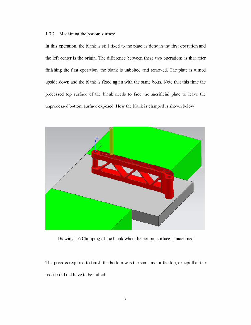
1.3.2 Machining the bottom surface
In this operation, the blank is still fixed to the plate as done in the first operation and
the left center is the origin. The difference between these two operations is that after
finishing the first operation, the blank is unbolted and removed. The plate is turned
upside down and the blank is fixed again with the same bolts. Note that this time the
processed top surface of the blank needs to face the sacrificial plate to leave the
unprocessed bottom surface exposed. How the blank is clamped is shown below:
Drawing 1.6 Clamping of the blank when the bottom surface is machined
The process required to finish the bottom was the same as for the top, except that the
profile did not have to be milled.

8
1.3.3 Machining the front surface
The center of the left Φ8mm hole is still the origin. And in this operation, the blank
could be directly clamped in the vise. To ensure that the front surface of the blank was
parallel to XY plane, a parallel bar was laid on the top of the vise, and the blank was
held up until the front surface of the blank touched the bottom of the bar. Then the vise
was tightened to fix the blank as shown below:
Drawing 1.7 Clamping of the blank when the front surface is machined
Note that the front and back surfaces are not parallel and the triangular through-holes
are perpendicular to the front surface. They need to be finished in this operation. Firstly,
the triangular through-holes are roughly milled with a 6.35 mm (1/4 inch) end mill and
finished with a 3.175 mm (1/8 inch) ball mill. Then the top half cylindrical undercut

9
surface on the left side and sloped pocket on the right side are milled with a 6.35 mm
(1/4 inch) end mill and a 3.175 mm (1/8 inch) ball mill.
1.3.4 Machining the back surface
The center of the left Φ8mm hole is the origin. The blank could also be clamped in the
vise. Since in this operation, the reference surface (“front”) faces down, the blank is
pressed down on the parallel bars to locate the blank square. The Drawing 1.5 below
shows how the blank was clamped:
Drawing 1.8 Clamping of the blank when the back surface is machined
In this operation, the bottom half cylindrical undercut surface is milled with a 6.35
mm (1/4 inch) end mill and a 3.175 mm (1/8 inch) ball mill.

10
1.4 Test and modification
While testing the preliminary processing plan using the CNC machine, a variety of
problems were encountered. The following are the problems and corresponding
modifications:
a. The profile of the part was not flat and smooth when it was cut and finished by the
CNC for the first time. Many levels of parallel lines, or striations, could be seen along
the part. The 19.05 mm (3/4 inch) end mill cut the whole profile level by level, and as a
result striations were visible, which can be seen from photos below:
Illustration 1.1 Tool marks caused by multiple-level cutting
The conflict is, when cutting the block, it is inappropriate for milling cutter to move for
only one loop to get a smooth surface, so it is necessary to let it cut material off by
multiple levels to avoid being broken or breaking the block. Then there would be no
allowance for finishing. The following approach was used to solve this problem: When
setting parameters in the CAM program (UG NX) which generates the tool paths for the

11
CNC mill, the diameter of end mill was changed from 19.05 mm to 19.56 mm (0.77
inch) before the G-code was generated. However, a 19.05 mm (3/4 inch) end mill was
still used to mill the profile, so there would be approximately 0.25 mm left after the end
mill cut off most material. Then the same cutter run again with the flute covering the
whole profile (from top to bottom) to cut the remaining material in a single pass. The
resulting profile was flat and smooth.
Illustration 1.2 Contrast of processed surface (top: initial trial; bottom: final part)
b. There were triangular tool marks on the bottom of the triangular pockets, which
resulted from using a 3.175 mm (1/8 inch) ball mill in finishing the bottom. A better
part was made by using a 3.175 mm (1/8 inch) end mill cutting the flat part of the
bottom of the pocket and a 3.175 mm (1/8 inch) ball mill cutting the fillets. The end
mills used were in general stronger than the ball mills, so for all subsequent
machining, end mills would be used more often for cutting off most material and

12
ball mills only for final steps such as filleting or contour area milling. This
modification resulted in faster material removal as well as reduced risk of breaking
tools.
Illustration 1.3 Contrast of processed bottom (top: milled with ball mill; bottom: milled
with end mill)
c. There were small steps on the sloped surface of this part shown in Illustration 1.5.
Step-overs were reduced to solve this problem at the expense of longer machining time.
For example, to reduce step-overs from “25% of the diameter of the tool” to “5% of the
diameter of the tool” in UG NX settings could make the space between adjacent loops
shorter but the time is quadrupled. Considering the shape the sloped surface, another
machining option, “contour area mill” may have been more useful. Unlike cavity mill
which cut off material level by level, contour area mill drives the tool to move along the
periphery of the part and finish all the area in one loop. However, adopting this
operation has a certain requirement: Most of the material needs to be cut off before

13
contour area mill is used. Otherwise, when the tool is following the periphery, the
material standing in its way may be too much for the tool to cut off at one time. As a
result, the tool is easy to be broken. For this reason, this operation was not used to
machine this feature. Further discussion, use and analysis will be stated later in this
thesis.
Illustration 1.4 Contrast of sloped surface processed with different step-overs
1.5 Complete processing route
The complete machining procedure is included in Appendix A: Full processing route of
Part 1.
1.6 Future work
After reviewing the machining processes used for manufacturing two pieces of Part 1, it
is clear that there are areas that could be improved. For example:
a. If properly placed, two parts could be cut from one block, which can save both
material and time;

14
b. Contour area milling was not used when making the first part. The curved surfaces
on the part processed by cavity milling could be processed better in less time by
contour area milling
c. Reaming the two through-holes would have been preferred over drilling them.
Fortunately, in the subsequent work, the lessons learned could be put into practice to
improve the process route.

15
Part 2
2.1 Description of Part 2
Drawing 2.1 Three-view drawing of CAD model of Part 2
This part has some similarities with the first part, so it appeared reasonable to machine
the part from four positions, which are named “top”, “bottom”, “side 1” and “side 2”.
Drawing 2.2 Four positions for multiple steps of processing

16
Note that this part looks like a distorted “L”. In the bottom view in the drawing 2.2, the
overall height of the part in the Y- direction is 105.45 mm (4.15 inch), which is
measured in CAD model. This distance is longer than most tools used for processing
this part. When a tool is milling the horizontal arm of the “L” from the top, the collet is
likely to hit the other upturned arm. Considering that, a plate was required to fix the
blank. There are many curved surfaces and smooth transitions on this part. Compared to
the machining of the first part, more ball millings and contour area milling were used to
finish the curved surfaces and transitions.
2.2 Determine the blank
Considering the profile of this part, “L” shape would waste a lot of material if each part
were machined from one rectangular block. Therefore, two blanks were positioned as
shown in Drawing 2.3. These two blanks have the same profile as the part but with an
offset of 2~3 mm.
Drawing 2.3 Place two blanks in one block

17
The order of cutting is very important. If the two blanks were cut from a block without
locating three holes, it would be difficult to locate the three centers of the holes on the
blank because the profile of blank is not square and is hard to measure size from its
sides. It is essential to locate and drill the three holes (six holes for two blanks) first.
After this, the blanks were cut using an abrasive waterjet cutter.
When machining, a bolt was used to fix the “U” fork through the Φ5mm hole (the
gray bolt shown in Drawing 2.4) to avoid the arms of the fork breaking off since the
arms are long and slender. This bolt may interfere with the tool that is milling the slot in
the “U” fork. This area is required to be machined beforehand to reserve space for the
bolt, which is shown in Drawing 2.4 below. In this operation, the blank was clamped in
the vise, and the tool only milled the top end of the fork.
Note: The tool could not move to the left too much otherwise the collet would touch the
upturned arm damaging the part. To avoid this, travel to the left of the origin was
limited to 28 mm for all tool path generation for this step.
Drawing 2.4 Simulations of the end mill interfering with the bolt and the preparation
work required to avoid this

18
2.3 Determine preliminary processing route
Since the height of this part is more than that of the vise, for all the four positions, the
vise cannot be used to grab the blank. When either arm of “L” is clamped in the vise
horizontally and the other arm points up, the latter would become an obstacle to tool
paths. As mentioned earlier, since the overall height of part is more than that of the vise,
one arm cannot be clamped in the vise horizontally with the other arm pointing down.
The latter may interfere with the foundation of CNC machine. Instead, a plate was used
for the clamping as depicted in Drawing 2.4. The blank could be fixed on the plate with
screws. Drilling three through-holes in the plate is enough for fixing the blank and
machining the “top”, “bottom” and “side 1 (or side 2)”, but the last two operations
cannot be processed in the same position. The reason is that the angle between two arms
of “L” is not 90 degrees. Since the plate is square, when the part is placed on the plate
with one of its arms parallel with one side of the plate, the other arm is not parallel with
the adjacent side.
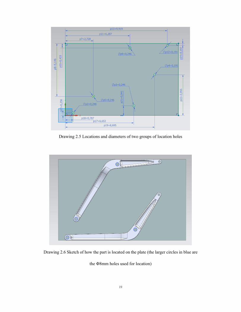
In this plate, two groups of through-holes were drilled. Each group has three
through-holes corresponding to three holes in the part. One group is used for the “top”
and “side 1” (the part below in Drawing 2.7), the other one is for the “bottom” and “side
2” (the part above in Drawing 2.7).
19
Drawing 2.5 Locations and diameters of two groups of location holes
Drawing 2.6 Sketch of how the part is located on the plate (the larger circles in blue are
the Φ8mm holes used for location)

20
When the part is placed on the plate as shown in Drawing 2.6, the end of the arm of the
“U” fork does not touch the plate and has to be supported to avoid breaking off. Three
supports were turned using a manual lathe, which are shown in Illustration 2.1. The
shorter one is applied between the plate and the part. The other longer two are for
holding the slot. One of them has been tapped inside. These small cylinders, combined
with a bolt and a nut, could meet the requirement of fixing for all the four positions. The
left picture shows how to support the impending fork when processing the top and
bottom surface. The shorter one supports the lower arm and the longer one supports the
higher arm. Here the longer one is the one with thread that could tighten the bolt. Note
that the bolt does not stick out of the upper surface otherwise it may interfere with tools.
The right picture shows how to support the impending fork when processing “side 1”
and “side 2”. Especially, when tools are processing the “side 2”, they engage in the
direction perpendicular to the bolt. Both arms need to be supported. The bolt has to go
through the long support in the middle (now it is the one without threads), stick out and
be tightened by the tapped long support.
Illustration 2.1 Different combination of supports for different processing position

21
Since it takes four steps to machine all the part, multiple references and clamping
methods were required:
2.3.1 Machining the top surface
In this operation, the centers of two Φ8mm holes in the part are chosen for location as
mentioned above. And the left center is chosen as the origin as shown below:
Drawing 2.7 Clamping of the blank when the top surface is machined
In this operation, the contour of the part is milled with a 19.05 mm (3/4 inch) end mill
first. Then the “long slots” (see Drawing 2.8) on the top surface is roughly milled with
a 9.525 mm (3/8 inch) end mill. Finally, the top surface is finished using contour area
milling with a 4.7625 mm (3/16 inch) ball mill.

22
Drawing 2.8 Long slots on top surface (the same on bottom surface) marked in orange
2.3.2 Machining the bottom surface
In this operation, centers of holes are still used for location. The center of the right
Φ8mm hole is chosen as the origin. After the top surface is processed, the blank is
unbolted and removed. Then the other group of holes in the plate is used to locate and
fix the blank, which is shown in Drawing 2.8:
Drawing 2.9 Clamping of the blank when the bottom surface is machined

23
The process required to finish the bottom was the same as for the top, except that the
profile did not have to be milled.
2.3.3 Machining the “side 1” surface
The blank is located and fixed in the same way as the top surface. However, in this
operation, the plate is set up and clamped in the vise as shown below:
Drawing 2.10 Clamping of the blank when the “side 1” surface is machined
In this operation, the triangular holes are milled roughly with a 6.35 mm (1/4 inch) end
mill and a 3.175 mm (1/8 inch) end mill. Then they are finished and chamfered with a
3.175 mm (1/8 inch) ball mill.

24
2.3.4 Machining the “side 2” surface
The blank is located and fixed in the same way as the bottom surface. However, in
this operation, the plate is set up and clamped in the vise as shown below:
Drawing 2.11 Clamping of the blank when the “side 2” surface is machined
The remaining area of “U” fork (part of the fork has been processed before) and the
slot near the fork are milled with a 12.7 mm (1/2 inch) end mill. Then the irregular slot
is finished using contour area milling with a 3.175 mm (1/8 inch) ball mill.
2.4 Test and modification
When testing the tool path in CNC, there were no obvious problems. Two steps need
to be paid attention to:

25
a. In the first operation, the technique applied on the first part could be used again to
get a smoother profile. That is, set the diameter of end mill to 19.56 mm in UG NX
and generate tool paths, but still use 19.05 mm (3/4 inch) end mill in actual
processing;
b. If 3.175 mm (1/8 inch) ball mill follows the 12.7 mm (1/2 inch) end mill in the last
operation, the risk of breaking the tool still probably existed and the processing time
was too long. Therefore, one operation “finish irregular slot with 1/4-inch ball mill”
was added between these two operations. The risk was reduced while the time was
shortened from 11 minutes to 5 minutes.
2.5 Processing procedure (complete route)
The complete machining procedure is included in Appendix B: Full processing route of
Part 2.

26
Part 3
3.1 Description of Part 3
Drawing 3.1 Three-view drawing of CAD model of Part 3
This part is different from the first two parts. On the one hand, almost all the areas that
need to be machined are on top of the part, which means there is no need to move or
turn the blank when machining most areas. But on the other hand, there is no vertical
wall around the part. It is difficult to grab the blank directly using the vise when the tool
is processing four sides. Instead, the four slots and holes distributed on the part could be
used for fixing the part. The whole machining process is a collection of cavity milling,
contour area milling and planar milling. End mills cut off material in the center and ball
mills were used when machining sloped surfaces and the four slots.
27
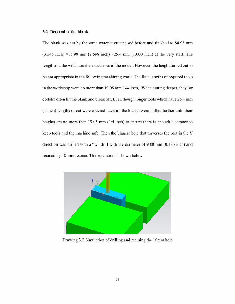
3.2 Determine the blank
The blank was cut by the same waterjet cutter used before and finished to 84.98 mm
(3.346 inch) ×65.98 mm (2.598 inch) ×25.4 mm (1.000 inch) at the very start. The
length and the width are the exact sizes of the model. However, the height turned out to
be not appropriate in the following machining work. The flute lengths of required tools
in the workshop were no more than 19.05 mm (3/4 inch). When cutting deeper, they (or
collets) often hit the blank and break off. Even though longer tools which have 25.4 mm
(1 inch) lengths of cut were ordered later, all the blanks were milled further until their
heights are no more than 19.05 mm (3/4 inch) to ensure there is enough clearance to
keep tools and the machine safe. Then the biggest hole that traverses the part in the Y
direction was drilled with a “w” drill with the diameter of 9.80 mm (0.386 inch) and
reamed by 10-mm reamer. This operation is shown below:
Drawing 3.2 Simulation of drilling and reaming the 10mm hole

28
This operation has to be finished separately and beforehand because only this operation
required the tool engaged from the front surface while in all the other operations the
tools engaged from the top of this part.
At last, four holes distributed on the part could be drilled using a 4.85 mm drill (#11
drill bit, 0.191 inch) which is smaller than the exact size because this preprocessing is
for location and the holes would be machined to the exact size in a subsequent
operation.
Illustration 3.1 Blank with location holes
3.3 Determine preliminary processing route
The whole process can be divided into two parts: “four corners” and “central part”. The
order of these two operations is determined based on these two principles:
i. The less the blank is relocated, the better the tolerances will be;
ii. Being grabbed by a vise is more accurate than being fixed by screws.

29
Therefore, the “four corners” need to be processed first since the vise could be used
when milling and finishing the “four corners” area. It will contribute to not only better
machining effects of four corners but also more accurate location for the following
process.
3.3.1 Machining the “four corners” surface
In this operation, one certain point is chosen as the origin. This point is an endpoint
which is selected at the bottom of the front surface on the CAD model, the projected
distance from the left side is 1.156 mm (0.0455 inch).
Drawing 3.3 Top view of the position of the origin [The blue point, on the front side,
1.156 mm (0.0455 inch) from the left side]
The blank was grabbed by the vise. It is worth noting that the left of blank is exposed
without covering by the jaw of the vise to let tools reach and process the two slots and
holes on the left, which is shown below:

30
Illustration 3.2 Grab part of the blank to make room for processing slots
Firstly, four slots are milled with a 6.35 mm (1/4 inch) end mill and semi-finished with
a 3.175 mm (1/8 inch) end mill. Then they are finished with a 6.35 mm (1/4 inch) ball
mill and a 3.175 mm (1/8 inch) ball mill using contour area milling.
3.3.2 Machining the “central part” surface
The blank is located in the same way as the first operation. A plate is required to fix
the blank in this operation. The length and width of the plate are no longer than those of
the part to avoid the pointed end of tools when they engage deeply and cut the sides of
the blank.
Illustration 3.3 Use 82-degree countersunk screws to fix blank on the plate

31
Similarly, the “central part” is milled with a 6.35 mm (1/4 inch) end mill and
semi-finished with a 3.175 mm (1/8 inch) end mill first. Then it is finished with a 6.35
mm (1/4 inch) ball mill and a 3.175 mm (1/8 inch) ball mill using contour area milling.
3.4 Test and modification
After following the route above to process the blank in CNC, some problems appeared:
a. The “cutting pattern2” of end mills were set to “follow periphery” in UG NX. When
milling the sloped surface, they left such tool marks like steps parallel to the short side
of the blank. In the following operation “contour area milling”, tool paths of ball mills
were set to “follow periphery” in the initial test. The ball mills move along the similar
tracks with smaller step-overs. As a result, tool paths of end mills and ball mills would
have overlaps and some steps left by end mills could not be finished by the ball mills,
which can be seen on the left of picture below; To mitigate this condition, the “cutting
pattern” of ball mills were set to “zig-zag”, which would let tools move along such
paths perpendicular to previous tool paths of end mills and clear away more remaining
material.
2 When inserting operations in CAM software (UG NX), there is an important setting called “cutting pattern”. It defines what kind of path the tool moves along when cutting off material from the blank. For example, by choosing “follow periphery”, the tool cut the blank along the periphery of the part. Choosing “zig-zag” makes the tool reciprocate.

32
Illustration 3.3 Contrast of processing effect on the sloped surface (left: “follow
periphery”; right: “zig-zag”)
b. To address the possiblity that smaller tools may hit walls and break off when
finishing the four slots, two different kinds of “trim boundaries3” were set, which are
shown as blue squares in Drawing 3.4 below: The bigger square confined the area
showed in deep blue where 6.35 mm (1/4 inch) end mill cut and the smaller square
confined the area showed in green and yellow where 3.175 mm (1/8 inch) end mill,
6.35 mm (1/4 inch) ball mill and 3.175 mm (1/8 inch) end mill cut. When smaller tools
are milling the slot, there is safe clearance between the tools and walls around them
.
Drawing 3.4 Two trim boundaries for different tools
3 “Trim boundaries” is another useful setting in UG NX. The tool is confined in a defined area. Only material inside the area could be cut off.

33
After finishing the four slots, 82-degree countersunk screws were used to fix the blank,
and the central part was milled and finished without relocation. Here it is important to
set “trim boundaries” to keep tools away from the screws. The difference between these
two kinds of processing sequences can be seen from the comparison below:
Illustration 3.4 Contrast of transition between two cutting areas with different
processing order (top: older route; bottom: modified route)
3.5 Processing procedure (complete route)
The complete machining procedure is included in Appendix C: Full processing route of
Part 3.
3.6 Future work
Here is another plan to process Part 3:
a. Select a thick block as the blank, with a height of more than 35 mm, that is, the
height of one part plus 15 mm;
b. Grab the lower part of this block with a vise and process all areas on the top;
c. Cut the processed half from the blank.

34
Although this plan may cause some waste of material, a better part would be expected.
This plan is worth putting into effect if there is suitable material and enough time.

35
References
1) Haas Automation, Inc. USA. (2015). Pocket Guide and Reference Charts for CNC
Machinists. Oxford, CA: Haas Automation, Inc. USA.
2) Peter Smid. (2003). CNC Programming Handbook, 2nd Edition. New York:
Industrial Press Inc.
3) Franklin D Jones, Henry H Ryffel, Erik Oberg, Christopher J McCauley, Ricardo M
Heald. (2004). Machinery's Handbook, 27th Edition (Toolbox Edition). New York:
Industrial Press Inc.
4) Online Instructor. (2015). NX 10 Tutorial: Sketching, Feature Modeling,
Assemblies, Drawings, Sheet Metal, and Simulation basics. CreateSpace
Independent Publishing Platform.

36
Appendix A: Full processing route of Part 1
Po. Step no. Step Tool no. Tool RPMFeed rate
(ipm)Stepover
Depth ofCut
Comment
1spot drill in the location of
two Φ8mm holesT2 Spot drill 1400 4.2
2drill holes for location and
fixingT3 #3 drill 2700 10.2
1 cavity mill profile by levels 40 25%flat 10%toolset diameter of
tool as 0.772 mill profile in one loop 40 10%flat 10%tool3 roughly mill triangel holes T7 1/4-in end mill 12000 48 25%flat 10%tool4 semi-finish corners T5 1/8-in end mill 12000 48 10%flat 10%tool5 finsh corners 3/16-in ball mill 12000 36 10%flat 10%tool6 chamfer T19 3/8-inch drill 12000 16.8 50%flat 0.25 in1 roughly mill triangel holes T7 1/4-in end mill 12000 48 25%flat 10%tool2 semi-finish corners T5 1/8-in end mill 12000 48 10%flat 10%tool3 finsh corners 3/16-in ball mill 12000 36 10%flat 10%tool4 chamfer T19 3/8-in drill 12000 16.8 50%flat 0.25 in
1roughly mill top halfcylinder and slope
T13 1/4-in ball mill 12000 48 25%flat 10%tool
2roughly mill triangel
through-holesT7 1/4-in end mill 12000 48 25%flat 10%tool
3finish triangel through-
holesT5 1/8-in end mill 12000 48 25%flat 10%tool
4finsh top half cylinder and
slopeT11 1/8-in ball mill 12000 48 5%flat 5%tool
5chamfer triangle through-
holesT19 3/8-in drill 12000 16.8 50%flat 0.25 in
1roughly mill bottom half
cylinderT13 1/4-in ball mill 12000 48 25%flat 10%tool
2 finish bottom half cylinder T11 1/8-in ball mill 12000contour areamill prefered
3chamfer triangle through-
holesT19 3/8-in drill 12000 12 0.04 in
manualoperation (front& back are not
parallel)
6 1manual drill Φ8mm holes
to exact diameter8mm drill 1400
reamingpreferred if
possible
5
1
T4
contour areamill prefered
3/4-in end mill 5000
2
contour areamill prefered
contour areamill prefered
3
4

37
Appendix B: Full processing route of Part 2
Pos. Step no. Step Tool no. Tool RPMFeed rate
(ipm)Stepover
Depth ofCut
Comment
1spot drill in the location
of two Φ8mm holesT2 Spot drill 1400 4.2
2drill holes for location
and fixingT3 #3 drill 2700 10.2
3spot drill in the location
of Φ5mm holesT2 Spot drill 1400 4.2
4roughly drill Φ5mm
holesT12 #12 drill 3000 9
5drill the hole to the
exact diameterT13 5mm drill 1400 8.4
reaming preferredif possible
6cut the blank along
outlinewater jet 0.1-0.2 in offset
2 1 mill the top of "U" fork T91/2-in
end mill4600 27.6
G-code is writtenby hand
1cavity mill profile by
levels40 25%flat 10%tool
set diameter oftool as 0.77
2 mill profile in one loop 40 25%flat 10%tool
3roughly mill long slots
on topT8
3/8-inend mill
12000 36 25%flat 0.1 in
4 finish top T123/16-inend mill
12000 48 25%flat
1roughly mill long slots
on bottomT8
3/8-inend mill
12000 36 25%flat 0.1 in
2 finish bottom T123/16-inend mill
12000 48 25%flat
1roughly mill triangel
holesT7
1/4-inend mill
12000 48 0.05 in 0.05 in
2 semi-finish corners T51/8-in
end mill12000 48 0.05 in 0.05 in
3 finsh and chamfer T111/8-in
ball mill12000 48 0.01 in
1 roughly mill "U" fork T91/2-in
end mill10000 40 50%flat 0.05 in
specify trimboundaries toavoid the bolt
2 semi-finish slot T131/4-in
ball mill12000 48 0.01 in
3 finsh slot T121/2-in
ball drill12000 48 0.01 in
6 1manual drill Φ8mm
holes to exact diameter8mm drill 1400
reaming preferredif possible
5
T4
1
3/4-inend mill
5000
3
4
5

38
Appendix C: Full processing route of Part 3
Pos. Step no. Step Tool no. Tool RPMFeed rate
(ipm)Stepover Depth of Cut Comment
1spot drill in
the location ofΦ10mm hole
T2 Spot drill 1800 3.6
2 drill holes T3 "w" drill 1400 8.4
3ream to theexact size
T410 mmreamer
730 7.3
1
spot drill inthe location offour Φ5.6mm
holes
T2 Spot drill 1800 3.6
2drill holes forlocation and
fixingT6 #11 drill 3000 10.5
3roughly millfour slots
T71/4-in end
mill7500 30 0.01scallop 0.01scallop
4semi-finish
cornersT5
1/8-in endmill
7500 15 0.003scallop 0.003scallop
5finish most
areas in slotsT13
1/4-in ballmill
7500 30 0.0005scallop
6 finish corners T113 mm ball
mill7500 15 0.0005scallop
1roughly millcentral part
T71/4-in end
mill7500 30 0.025scallop 0.025scallop
2semi-finishcentral part
T51/8-in end
mill7500 15 0.0125scallop 0.0125scallop
3finish most
areas incentral part
T131/4-in ball
mill7500 30 0.0005scallop
4finish corners
and filletsT11
3 mm ballmill
7500 15 0.0005scallop
pay attentionto clamping
and trimboundaries
3pay attention
to avoidscrew caps
1
2

39
Vita
Longfu Hu was born in Wuhu, Anhui Province, China. Between 2010 and 2015 he
studied Mechanical Engineering and Japanese at Dalian University of Technology in
Dalian, China. Then he entered into P.C. Rossin College of Engineering and Applied
Science of Lehigh University to pursue his Master of Science degree. His research area
is CAD/CAM and process design.


![CNC Milling[1]](https://static.fdocuments.in/doc/165x107/55cf9cd7550346d033ab3f24/cnc-milling1.jpg)