CM CME1856W and CME2006R Technical Training Training...2020/02/02 · –Pugre Vavel – Air cooled...
86
Technical Training Technical Training CM 3 - CME1356, CME1656, CME1856W and CME2006R
Transcript of CM CME1856W and CME2006R Technical Training Training...2020/02/02 · –Pugre Vavel – Air cooled...
Technical TrainingTechnical TrainingCM3 - CME1356, CME1656, CME1856W and CME2006R

• CM3 product– 48” wide– 24” deep– 28” high– R-404A– Purge Valve– Air cooled– Water cooled– Remote air cooled
CME1356 and CME1656CME1356 and CME1656

CME2006R & CME1856WCME2006R & CME1856W
• CME2006R– Remote Only– Use with ERC611 – Uses Copeland Scroll
Compressor• CME1856W
– New in 2002– Same compressor as
CME2006– Water Cooled Only

Presentation TopicsPresentation Topics
• Product Construction• Installation• Operation• Cleaning & Maintenance• Service Diagnosis• Refrigeration Service

ModelsModels
• CME1656, CME1856 & CME2006– 6 evaporators
• CME1356– 5 evaporators
• CM3 technology– Automatic harvest time adjustment– No seasonal adjustments– Controller aided diagnostics– Adjustable purge

Installation: All ModelsInstallation: All Models
• Level the bin in the place where it will be located
• Use NEW plumbing -do NOT recycle old tubing!– Water must flow in at
2.7 GPM – Minimum 20 PSI– Use triple SSM filter
system

Air CooledAir Cooled
• Air flow– In the front and out the
back up to E series – E series flows in the front
& left side and then out the back
– E Series new in 2002• Left side panel changed
to louvered type
• Disposable air filter clipped to panels– Easy to change

Vented Drain
Air Cooled InstallationAir Cooled Installation
• 3/4” FPT drain– Use rigid pipes– Vent the drain - 18”
• 3/8” Male flare inlet– Use NEW 3/8” tubing - do not
recycle old tubing!– Change filter cartridges!
• Electrical junction box inset into back panel
Potable WaterInlet
Purge Valve Drain

Water Cooled InstallationWater Cooled Installation
• 3/4” FPT purge valve drain - must be vented
• 3/8” Male Flare potable water inlet
• Water Cooled:– 1/2” FPT condenser
drain– 3/8” FPT condenser
inlet– 1/2” FPT condenser
inlet for CME1856W
• Electrical junction box inset in back panel
Potable Water Inlet
Condenser Water Inlet
Vent
DrainCondenser Drain - Do NOT Vent

Remote Air CooledRemote Air Cooled
• No louvers– Quieter operation
• Refrigeration system– Liquid & Discharge
check valves– Headmaster in
condenser– No pump down– Top inlet receiver
• No king valve
Liquid Line
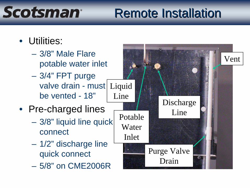
Remote InstallationRemote Installation
• Utilities:– 3/8” Male Flare
potable water inlet– 3/4” FPT purge
valve drain - must be vented - 18”
• Pre-charged lines– 3/8” liquid line quick
connect– 1/2” discharge line
quick connect– 5/8” on CME2006R
Vent
Purge Valve Drain
Discharge LinePotable
Water Inlet

Remote InstallationRemote Installation
• All models have the electrical junction box inset into the back panel
• Remote models also have the fan power wires in the same box

Remote InstallationRemote Installation
• Select the location for the ice machine and condenser– Minimize line set length for ease of installation– Follow Scotsman’s guidelines for location

22
.8
7"
17
.1
5"
40.35"hd
rd
ddTotal DropCannot Exceed15 feet
hd= horizontal distancerd= rise distance x 1.7dd= drop distance x 6.6hd+rd+dd=total
Remote InstallationRemote Installation

• Typical Installation– Condenser above ice
machine– Precharged line set
coiled within building• Use horizontal coil• NEVER leave excess
coiled up on the roof!
Remote InstallationRemote Installation

ERC411/611 - Leg Location when Shipped
Remote CondenserRemote Condenser
• For CME1356R or CME1656R– Use ERC411– or MAC “G” or “X”
with a RCKCME6GX accessory
• RCKCME6GX required to add headmaster to the central condenser
• CME2006R– Use ERC611 ONLY!

Clean and Lubricate Quick Connect
Couplings
Use Two Wrenches to
Tighten
Rotate Swivel Nut OneQuarter Turn More After
Nut Becomes Tight
Remote InstallationRemote Installation

Thermostat Bulb
Routing Tube
Installation: Bin ThermostatInstallation: Bin Thermostat
Bracket
Snap Cap Tube Into
Slot
Insert Bulb Tip

Secure Thermostat Bulb and Bracket to the Bottom of the
Machine with Two Fasteners
Pull Excess Cap Tube Back into Machine
Compartment
Installation: Bin ThermostatInstallation: Bin Thermostat

Initial Start UpInitial Start Up
• Remotes: Supply electrical power 4 hours before starting compressor
• Remotes: Open liquid line valve • All models: Switch on the water supply• All models: Check voltage - compare to
nameplate• All models: Push Freeze to start

Scroll CompressorScroll Compressor
• CME1856 & CME2006• Three phase
– Must run in proper direction– But Will run either CW or CCW– Wire phasing controls direction– Switch two lead wires to change
direction

Liquid Line Valve: Remote Liquid Line Valve: Remote
• Valve must be opened fully (stem in the UP position) to open the path from the receiver to the TXV
• Open partially to recover, evacuate and recharge
• There is NO discharge access valve
Liquid LineValve

Operation: Initial Start UpOperation: Initial Start Up
• Purge valve opens for 30 seconds• Hot gas valve opens for 30 seconds• Water pump is on• Purge and hot gas valves shut off• Water valve opens and fills the reservoir• Compressor starts -
– AFTER reservoir is full• No manual adjustments

ComponentsComponents
• Inlet water valve– Flows 2.7 GPM– 24 volt coil
• Purge valve– Powered by purge valve
timer– 220 volt coil
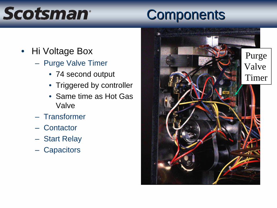
• Hi Voltage Box– Purge Valve Timer
• 74 second output• Triggered by controller• Same time as Hot Gas
Valve– Transformer– Contactor– Start Relay– Capacitors
ComponentsComponents
PurgeValve Timer

ComponentsComponents
• At the front– Controller– Bin
thermostat– Refrigeration
system access valves
– Water pump– Water level
sensor

System ControllerSystem Controller
• Connected to sensors– Water level– Water temperature– Ice – Bin thermostat– Discharge temperature
• Controls loads– Water, purge, hot gas, and
bypass (remote) valves– Contactor and water pump– Fan motor (air cooled)

Blue ControllerBlue Controller
• Last Error Recall– Shut unit off– Hold Off button until Green lights
appear– Push and release Harvest button to
show last error code– Push and release Harvest button
again to show second to last error code

Service ControllerService Controller
• Single Service Controller– For all existing CM3
models– Model selection table
on back and in the instructions
– Model selected by rotary switch

ComponentsComponents
• Evaporator cover over the ice making zone– Provides thermal
barrier• Push up to release at
the bottom

Front Ice Sensor
ComponentsComponents
• Under the evaporator cover– Two more covers to
keep ice out of the reservoir
– Water pump discharge hose
– Front ice sensor
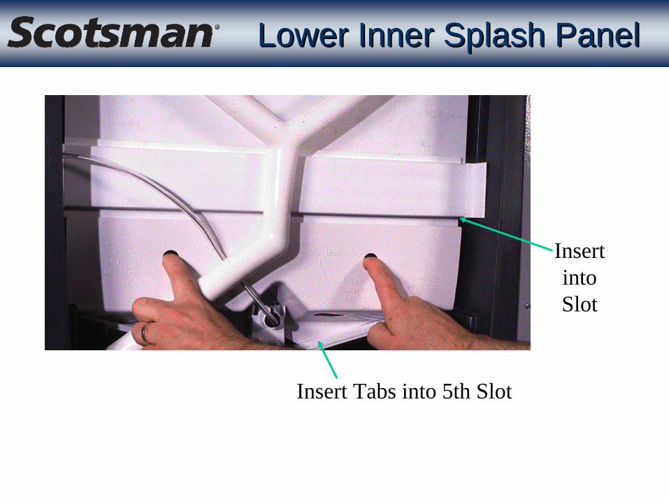
Insert Tabs into 5th Slot
Insert intoSlot
Lower Inner Splash PanelLower Inner Splash Panel

“6th” Evaporator
Evaporator SupportBracket
Water Trough -Must be in this
position
Cube Deflector
Freezing CompartmentFreezing Compartment
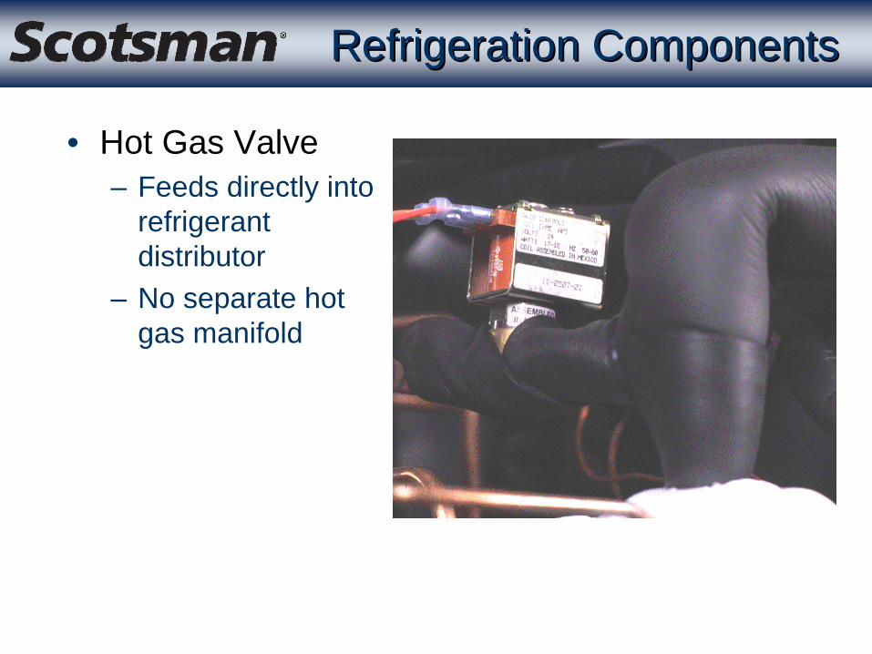
Refrigeration ComponentsRefrigeration Components
• Hot Gas Valve– Feeds directly into
refrigerant distributor
– No separate hot gas manifold

Refrigeration ScrollRefrigeration Scroll
• ZS30K4E compressor– Z = Z family– S = Medium temp– 30K = 30,000 BTUH base
capacity– 4 = 4th generation (2nd
generation refrig. Scroll)– E = Ester oil

Scroll CompressorScroll Compressor
• Single Phase– Must also run in proper direction– Can reverse if stopped & immediately restarted– CME1856 & CME2006 single phase models have
short term (less than 1 second) power interruption relay to delay compressor restart for 30 seconds

Liquid Line Check Valve
Discharge Line Check Valve
Harvest Bypass Valve
Remote RefrigerationRemote Refrigeration

Headmaster
Remote RefrigerationRemote Refrigeration
• Headmaster inside the ERC411 remote condenser
• Maintains minimum discharge pressure during freeze - 240 PSIG

• Headmaster inside the ERC611 remote condenser
• Maintains minimum discharge pressure during freeze - 217 PSIG
Headmaster
Remote RefrigerationRemote Refrigeration

Receiver
ThermostaticExpansion Valve
Evaporator
Evaporator
Evaporator
Compressor
Remote Condenser
Refrigerant Distributor
Hot GasValve
Check Valve
Check Valve
Suction
Discharge Line
Accumulator
ProcessPort
Head PressureControl Valve
Harvest
Bypass
Valve
HeatExchange

Water SequenceWater Sequence
• Reservoir drains during harvest– Amount varies depending upon level of purge set on
controller– Pump start time determines amount of water purged
out• Partial refill during harvest• Top off at the beginning of freeze• Refill once more half-way thru freeze
Electrical Sequence: FreezeElectrical Sequence: Freeze
• Reservoir water must cool to a preset point within 5 minutes after the freeze cycle begins– Controller checks water and discharge temps to see
if refrigeration is taking place– Will go thru a multiple step diagnostic if it is not

Electrical Sequence: FreezeElectrical Sequence: Freeze
• Water pump will switch off for a few seconds early in the freeze cycle
• Coats the evaporators with a thin layer of ice– Promotes better water distribution

Electrical Sequence: FreezeElectrical Sequence: Freeze
• About 1/2 way thru the freeze cycle the float stem in the water sensor will break the top beam of the water level sensor and the water valve will open to refill the reservoir
• The next time this happens starts the end of the freeze cycle

Upper Eye
Lower Eye
Water ControlWater Control
• The controller senses how much water is in the reservoir thru the water level sensor– Upper electric eye indicates
when water falls– Lower electric eye indicates
when water rises

Electrical Sequence: FreezeElectrical Sequence: Freeze
• Fan Control (Air Cooled)– Fan off time determined by discharge temperature
taken early in the freeze cycle• Lower discharge temperature = longer fan off time to
build up heat for harvest– In low ambients the fan will cycle on and off
throughout the freeze cycle– The Fan is Off during harvest

Electrical Sequence: HarvestElectrical Sequence: Harvest
• Harvest time for any cube ice machine will vary depending upon:– Ambient temperature– Incoming water temperature– Degree of mineral scale build up
Harvest CycleHarvest Cycle
• The first harvest will be about 6 minutes long– Allows enough time for all ice to harvest – Controller will be timing from the beginning of
harvest until when the last cube fell thru the ice sensor’s “light curtain”

Harvest BeginsHarvest Begins Harvest EndsHarvest Ends
Harvest Harvest BeganBegan HarvestHarvest
EndedEnded
Total Current Harvest Cycle TimeTotal Current Harvest Cycle Time(prior cycle actual + a % of actual)(prior cycle actual + a % of actual)
Actual Time to Release IceActual Time to Release Ice(prior cycle)(prior cycle)
Percent of ActualPercent of Actual
Last Cube Last Cube FellFell
Ice Sensing / Harvest ControlIce Sensing / Harvest Control

Located at the Front and Back of the ice chute
Infrared EmitterInfrared Receiver
Prior Ice SensorPrior Ice Sensor

New Ice SensorNew Ice Sensor
• Modular Cuber Sensor -– Two piece construction
• Holder• Photo-eye module
• Interchangeable with prior sensors
Module
Holder

Ice SensorIce Sensor
• Push in on front of sensor module to release it from the holder

Ice SensorIce Sensor
• When sensor module is released, it can be easily cleaned with a soft cloth or swab
Photo Eye Lens

Ice SensorIce Sensor
• Re-assemble the sensor– Tuck wire under the clip– Push module into place– Be sure wire doesn’t stick
out past edge of holder

Electrical Sequence: HarvestElectrical Sequence: Harvest
• Fan is off (air cooled)• Harvest bypass valve opens for a few seconds
(remote)• Pump is off for a varying amount of time
depending upon purge level• Hot gas valve is open• Purge timer has power and has opened the
purge valve– No water drains until the pump starts

Electrical Sequence: HarvestElectrical Sequence: Harvest
• Pump re-starts• 74 seconds after the beginning of harvest the
purge valve timer closes the purge valve• The inlet water valve opens for 30 seconds• Harvest continues until the controller stops it

End of HarvestEnd of Harvest
• Time expired– Either the unit returns to freeze or – It shuts off on Bin Full - when the bin thermostat
contacts are closed– If ice was not “seen” by the ice sensors
• Will make one more cycle• If it happens again, the unit shuts down• Will automatically restart for another try in 50 minutes

RestartsRestarts
• Electrical Power Interruption– Automatic restart
• Open the hot gas valve for 20 seconds• Open the purge valve• Start the pump• Shut the purge valve• Fill the reservoir• Start the compressor, freeze for 30 seconds• Harvest for 6 minutes

RestartsRestarts
• Water supply interruption– Automatic shut off and restart
• Shuts off when float does not rise enough during water fill
• Controller checks for water by opening the inlet water valve every 20 minutes
– Will restart when the float rises far enough to break the bottom beam in the water level sensor

Ice and EvaporatorsIce and Evaporators
• Ice Formation– Refrigerant enters the evaporators at the top– Cubes will form at the top first– Ice harvests mostly as vertical strips - not individual
cubes– Strips break up when impacting the cube deflector

Operation: Purge AdjustmentOperation: Purge Adjustment
• There are 5 levels– Maximum– Heavy– Standard - the factory setting– Moderate– Minimum
• Number of green lights indicates purge level

• Push Harvest to release any ice and warm the evaporators
• Push Clean and add 24 ounces of cleaner
• After 10 minutes push Clean again to flush out the cleaner
• After 20 minutes push off to stop
Cleaning and SanitationCleaning and Sanitation
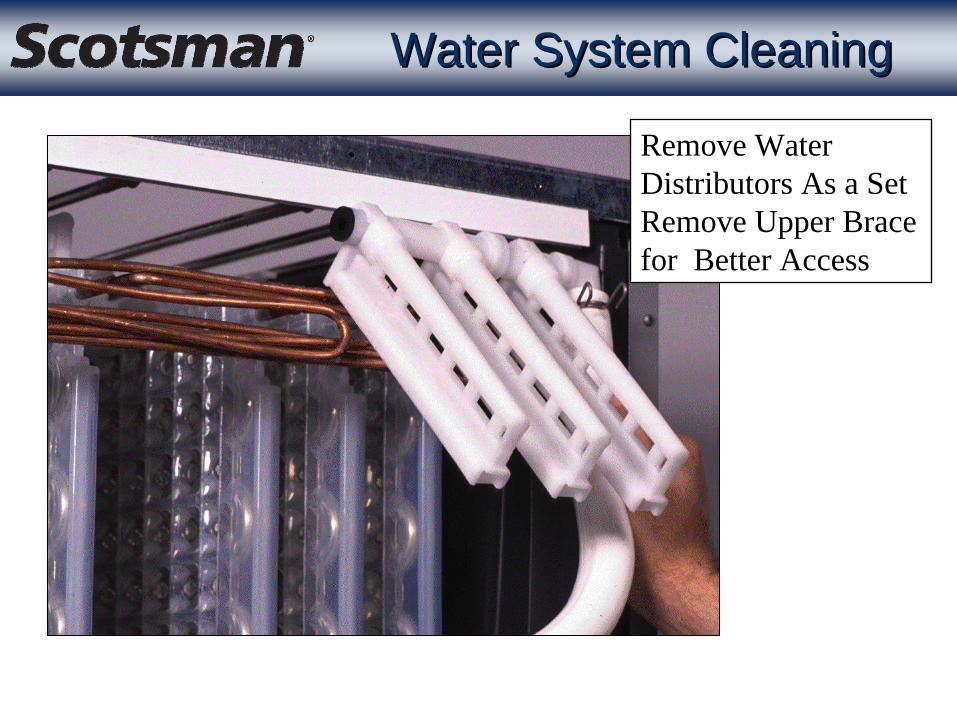
Remove Water Distributors As a SetRemove Upper Brace for Better Access
Water System CleaningWater System Cleaning

Hold Purge Valve Open Push and hold OFF until unit stops, Push and hold Clean and
the unit will drain
Draining the ReservoirDraining the Reservoir

Top Half of Shroud is Removable
Split Condenser Fan ShroudSplit Condenser Fan Shroud

Service ProceduresService Procedures
• Air Cooled Fan Motor Change– Begin by removing
the water pump and– Disconnecting the
water line from the inlet water valve

Service ProceduresService Procedures
• Fan Motor– Loosen set screw
holding fan blade to motor shaft
– 1/8” hex wrench
Service ProceduresService Procedures
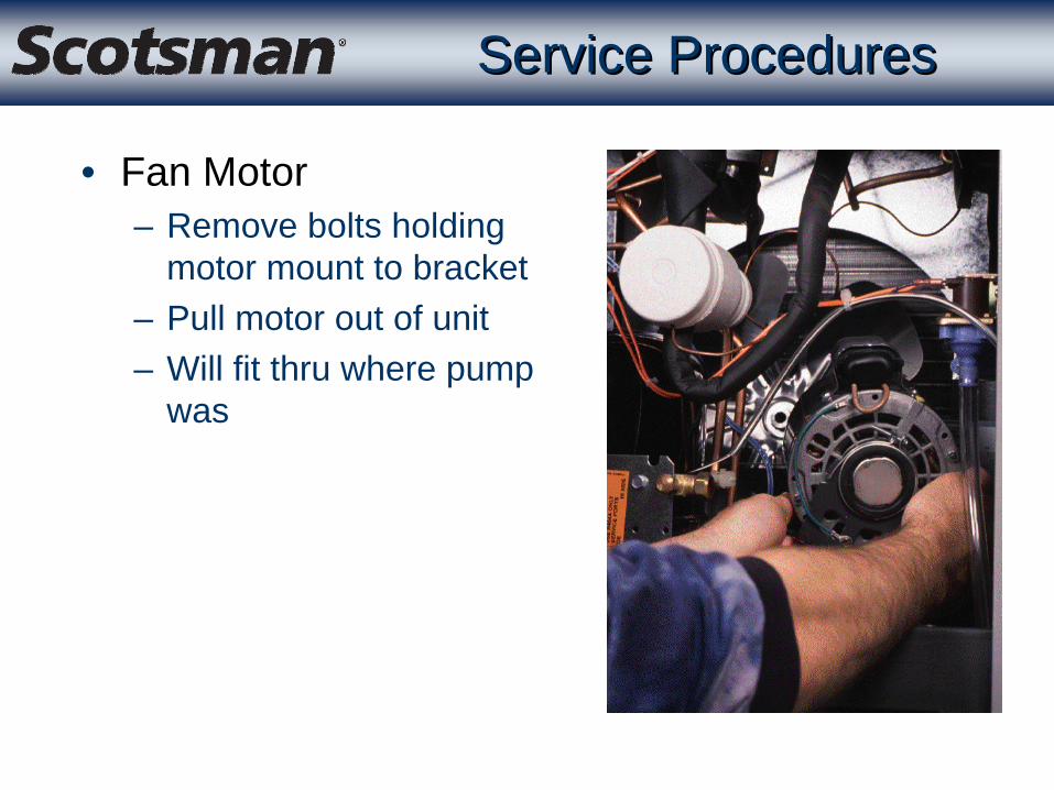
• Fan Motor– Remove bolts holding
motor mount to bracket– Pull motor out of unit– Will fit thru where pump
was

Service DiagnosisService Diagnosis
• No ice, machine is off– Check the controller for lights
• No lights = no power to controller– Check for power to machine– Check for transformer output

Service DiagnosisService Diagnosis
• If there are lights - which ones are on?– Off light means the machine was switched off by
someone– A Diagnostic light means a machine malfunction– Bin Full light means something has triggered either
the bin thermostat or the ice sensors are blocked

Service DiagnosisService Diagnosis
• Water Diagnostic Light– Blinks once and repeats
• Water pump may not be working– Blinks twice and repeats
• Water flow into machine too slow– Is ON without blinking
• Inlet water valve leaking thru rapidly
– If both the Water AND Refrigeration lights are on, check the thermistor set

Service DiagnosisService Diagnosis
• Refrigeration Light– Blinks once and repeats
• Ice release very slow, took maximum length harvest
– Blinks twice and repeats• No ice sensed during maximum
length harvest– Blinks three times and repeats
• High discharge temperature

Service DiagnosisService Diagnosis
• Refrigeration Light– Is ON without blinking
• Low discharge temperature OR• Maximum length freeze cycle OR • Water cooled or remote may
have cut out on high discharge pressure
– Control resets automatically, but the controller may have timed out, depending upon when in the freeze cycle the control reset

Service DiagnosisService Diagnosis
• Bin Full light is ON– Bin may be full– 4 minute delay– Thermostat may be
closed - is bin very cold?– Ice sensors may be
blocked• Could need cleaning
Service DiagnosisService Diagnosis
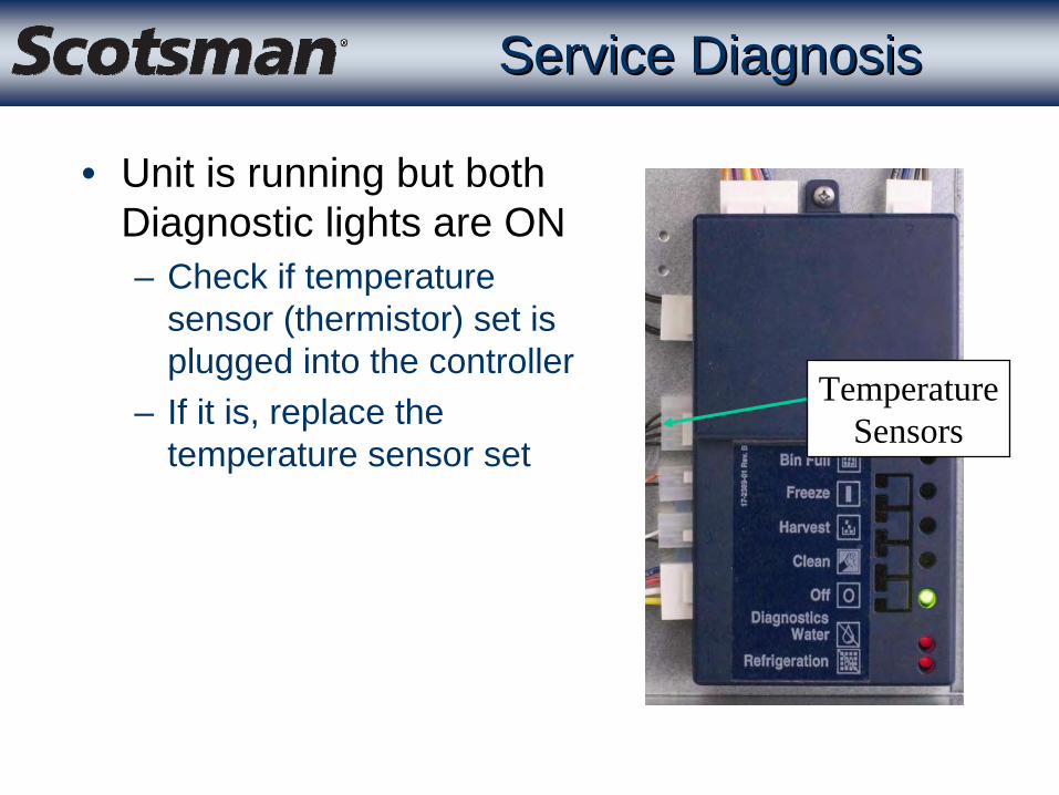
• Unit is running but both Diagnostic lights are ON– Check if temperature
sensor (thermistor) set is plugged into the controller
– If it is, replace the temperature sensor set
TemperatureSensors

CompressorTXV
Hot Gas ValveHeadmaster
Charge
Refrigeration DiagnosisRefrigeration Diagnosis

Compressor Will Not StartCompressor Will Not Start
• Check for voltage to compressor• Check resistance of windings
– Overheated internal overload will show “open”windings
• Check start relay• Check start capacitor

CompressorCompressor
• Trips overload– Most likely it’s a problem with a starting component
• Start relay• Start capacitor
– May be overheating• Too much superheat - should be no more than 20oF.
five minutes into freeze• Hot gas valve leaking thru• Low charge
CompressorCompressor
• Trips breaker– Check for shorted winding or short to ground– Could be defective breaker - check amp draw
• Low capacity– Check for ice machine cause - TXV, hot gas valve,
low charge, inlet water valve leak thru OR high ambients!

Thermostatic Expansion ValveThermostatic Expansion Valve
• Controls refrigerant flow to maintain suction line temperature
• Bulb must be securely clamped to suction line AND insulated

Thermo Expansion ValveThermo Expansion Valve
• Superheat - most consistent near the end of freeze– Superheat control point will be between 8 and 14
degrees– Superheat also changes as the valve modulates– The valve is NOT adjustable

Low Refrigerant ChargeLow Refrigerant Charge
• Remotes– With a minimum charge the ice machine can start up
BUT part way thru a freeze cycle refrigeration may stop and what ice has been made will fall off the evaporators
– Will eventually stop on Maximum freeze cycle

Hot Gas ValveHot Gas Valve
• Leaks thru during freeze– Check by temperature at valve
• Should be warm but NOT hot on inlet– Hot inlet means valve is leaking thru
• Opens partially - no ice release– Very low (half normal) suction pressure in harvest
• With normal amount of ice on evaporators– Hot thru the valve but cold at the refrigerant
distributor

Remote: No refrigerationRemote: No refrigeration
• Controller: Refrigeration Light ON• Low discharge pressure in Freeze
– Low charge• Recover and weigh OUT charge• If low, locate and REPAIR the LEAK
– Headmaster will not close liquid line• Can only check when condensing temp is below 70oF.• Replace headmaster IF confirmed

Liquid ChargeLiquid Charge
Weigh In ChargeWeigh In Charge
Evacuate to 300 micronsEvacuate to 300 microns Use Nitrogen PurgeUse Nitrogen Purge
Use HFC Leak DetectorsUse HFC Leak Detectors
RR--404A404A
Refrigeration ServiceRefrigeration Service

SummarySummary
• Four models– CME1356 with 5 evaporators– CME1656 with 6 evaporators– CME1856W & CME2006R - scroll
• CM3 technology– Controller aided diagnostics
• New enhanced remote system• Reservoir purge valve• R-404A