Clinical Anatomy of the Lumbar Spine &Amp_ Sacrum
251
Transcript of Clinical Anatomy of the Lumbar Spine &Amp_ Sacrum


� -.
Clinical Anatomy of the Lumbar Spine and Sacrum

For Elst'Vier
Senior Commissioning Editor: Sarena Wolfaard Project Developmellt Mrmoger: Claire Wilson Project Mallager: Morven Dean Desigll: Judith Wright Illustration Malinger: Bruce Hogarth

Clinical Anatomy of the Lumbar Spine and Sacrum
Nikolai Bogduk BSe (Med), MB BS PhD, MD, DSe, DipAnat Dip Pain Med, FAFRM FAFMM,
FFPM (ANZCA)
Professor of Pain Medicine, University of Newcastle, and
Head, Department of Clinical Research,
Royal Newcastle Hospitaf, Newcastle,
New South Wales, Australia.
Foreword by
Stephen M. Endres MD DABPM
President, Internationa/Spine Intervention Society,
Associaft: Clinicol Professor of Anesthesiology,
University of Wisconsin Medical School and
Associate Clinical Professor of Nursing,
University of Wisconsin, feu Claire.
Wisconsin, USA.
FOURTH EDITION
!I�'. �'
;i I ELSEVIER
CilURClI1LL LlvrNG�TONI'
EDINBURGH LONDON NEW YORK OXFORD PHILADELPHIA ST LOUIS SYDNEY TORONTO 2005

ELSEVIER CHURCHILL
UVINGSTONE
Longman Group UK Limited 1987
Pearson Professional Limited 1997
Harcourt Brace and Company Limited 1988
Harcourt Publishers Limited 2001
Elsevier Science Limited 2002
e 2005, Elsevier UmHed. AU rights reserved.
The right of Nikolai Bogduk to be identified as author of this work has been asserted by him in accordance with the Copyright, Designs and Patents Act 1988
No part of this publication may be reproduced. stored in a retrieval system, or transmitted in any form or by any means, electronic, mechanical, photocopying, recording or otherwise. without either the prior pennission of the publishers or a licence permitting restricted copying in the United Kingdom issued by the Copyright Licensing Agency, 90 Tottenham Court Road. London WIT 4LP. Permissions may be sought directly from Elsevier's Health Sciences Rights Department in Philadelphia, USA: phone: (+1) 215 238 7869, fax: (+1) 215 238
2239, e-mail: [email protected]. You may also complete your request on-line via the Elsevier Science homepage (http://www.elsevier.com).by selecting 'Customer Support' and then 'Obtaining Permissions'.
First edition 1987
Second edition 1991
Third edition 1997 Fourth edition 2005
ISBN 0 443 10119 I
British Library Cataloguing in Publication Data
A catalogue record for this book is available from the British Library
Library of Congress Cataloging in Publication Data
A catalog record for this book is available from the Library of Congress
Notice
Knowledge and best practice in this field are constantly changing. As new research and experience broaden our knowledge, changes in practice, treatment and drug therapy may become necessary or appropriate. Readers arc advised to check the most current information provided (i) on procedures featured or (ii) by the manufacturer of each produd to be administered, to verify the recommended dose or formula, the method and duration of administration, and contraindications. It is the responsibility of the practitioner, relying on their own experience and knowledge of the patient, to make diagnoses, to detennine dosages and the best treatment for each individual patient, and to take all appropriate safety precautions. To the fullest extent of the law, neither the pubusher nor the author assumes any liability for any injury and/or damage.
your source for books, journals and multimedia in the health sciences
www.elsevierheolth.com
Printed in China
The Publisher

Contents
Forrword vii
Preface to the fourth edition ix
Preface to the first edition xi
1. The lumbar vertebrae
2. The interbody joint and the intervertebral
discs 11
3. The zygapophysial joints 29
4. The ligaments of the lumbar spine 39
5. The lumbar lordosis and the
vertebral canal 51
6. The sacrum 59
7. Basic biomechanics 63
8. Movements of the lumbar spine 77
9. The lumbar muscles and their fasciae 97
10. Nerves of the lumbar spine 123
11. Blood supply of the lumbar spine 141
12. Embryology and development 149
13. Age changes in the lumbar spine 165
14. The sacroiliac joint 173
15. Low back pain 183
16.lnstability 217
17. Radiographic anatomy 227
Appendix 237
Index 241
v

Foreword
When asked to write the Foreword to the fourth edition of Clinical Anatomy of 1111." Lumbar Spille and Sacrum I felt honoured and privileged. I have known and worked with Dr Nik Ilogduk for the last 10 years, and I have always respected him for his academic integrity.
Historically, therapeutic injections were done by an anaesthesiologist in a recovery room in between cases. Most procedures were done using the surface anatomy landmarks and a sense of feel to guide the needle to the supposed target area. Large doses of local anaesthetic and steroids were used to ensure that at least a portion of the injectate would get to the suspected pain generator. This, in many cases, was effective in treating certain acute inflammatory conditions along the spine, but it certainly was never intended to be a technique that had any diagnostic value. Over a decade ago, thanks to the efforts of physicians such as Charlie Aprill, Rick Derby and Nik Ilogduk (founding fathers of the International Spine Intervention Society), fluoroscopy was shown to be of great value nol only for verifying needle placement for therapeutic injections, but its diagnostic utility also became obvious. As a member of ISIS, in the early 19905 I saw a renewed interest in spine anatomy as well as its accompanying musculoskeletal components. Physicians attending the early cadaver courses for the first time could see where the tip of the needle was going. In order to understand exactly what was going on, a review of basic spinal anatomy and biomechanics was imperative. Texts such as Dr Bogduk's C/i"ieal Anatomy of tlte Lumbar Spine became required reading in order to grasp what they were seeing and doing with the needle. More importantly, texts such as these were significant in
helping the interventionalist understand the responses they saw to the injections.
During my time as Chairman of the Education Committee for [SIS, I witnessed incredible advancements in the technical complexity of spinal intervention procedures. However, with this increase in complexity of technjques came an increase in complications to the patient. As fluoroscopically guided spinal techniques became more popular and accepted, cadaver courses sponsored by many different organizations started to crop up all over the United States. My concern was that many of these courses taught the entire spectrum of spinal intervention techniques in less than two days, with usually less than one hour spent on basic anatomy and biomechanics of the spine. More time was spent discussing how to charge and how to code than spent on radiographic anatomy of the spine.
Due to this observation, as well as reports of more complications to patients from spinal interventions, ISIS made a concentrated effort to go back to basics; even the most experienced spinal injectionist would have difficulty learning or mastering even a fourth of what was presented at these multiple modality courses. In light of this, we felt the best way to teach spinal interventions was by implementing a very structured tier of cadaver courses, which began with basic science and anatomy of the spine, including radiographic anatomy as well as very basic lumbar and sacral injections. We also felt it imperative that all students should start with basic science and lumbar courses and only then be qualified to advance to complex anatomy and spinal injection techniques. As these courses became more structured and organized, we found that Dr Bogduk's book, C[il/ical A1Ialomy of the Llimbar Spi"e, became not only required reading, but it was the key reference for instructors to review prior to teaching the courses.
The timing of this fourth edition is perfect, for now we have reached the age of 'minimally invasive'
vii

viii FOREWORD
procedures used to treat pain generators of the spine. Chapters on disc pain and posterior element pain stress not only the anatomy of these structures but also review the pathophysiology of the degenerative process and its relationship to pain. More importantly. these chapters stress what biomechanical changes may occur as a result of doing destructive procedures.
After reading the fourth edition in preparing to write this Foreword, 1 a,m humbled by how much 1 have learned (or how much I have forgotten) about the basic anatomy and biomechanics of the lwnbar spine and sacrum. I found myself learning and relearning many things I could apply on a daily basis to my practice of spinal interventions and pain management.
I was reminded how important it is to have a firm understanding of the basic structure of the spine and its innervation in order to treat patients. I cannot imagine anyone placing needles in or around the tissue layers and neural elements of the spine without having a firm grasp as to what the short and long-term effects may be as a result of these procedures. I highly recommend this book to any physician or health care provider involved in spine care. A firm understanding of this book will provide any spinal interventionist with the foundation necessary to diagnose and treat patients with spinal pain.
Stephen M. Endres Eau Claire, 2005

L
Preface to the fourth edition
Anatomy changes little . The structure of bones, joints, ligaments and muscles remains the same as it always has been. It becomes difficult, therefore, to answer a publisher's request for a new edition. It seems artificial to amend a text when the subject matter has not substantially changed. From time to time, however, new insights are brought to light, or errors of observation in the past are corrected. Minor though these may be, there is merit in bringing them to light.
There has been no need to change the fundamental thrust of this book since its first edition. The basic structure of the lumbar spine has not changed. For the fourth edition, only minor changes have been made in those sections pertaining to morphology and function. The structure and embryology of the iliolumbar ligament continues to be controversial. New observations on the fascicular anatomy of the quadratus lumborum have appeared. Nerves have been shown to grow into damaged intervertebral discs. Further studies have shown the sacroiliac joint to have a minimal range of motion.
Where major changes have occurred is in the application of anatomy to clinical issues. Accordingly,
the major changes in this fourth edition occur in the chapters pertaining to the causes of back pain. Over the first three editions, certain themes emerged and evolved. They have continued to do so. For some, such as zygapophysial joint pain, more recent data are sobering. The prevalence of zygapophysial joint pain may not be as high as previously believed. Conversely, the amount of data on discogenic pain has increased. What was ventured as a concept in the first edition has become more consolidated. Studies have progressively supported the morphology and diagnosis of internal disc disruption. Recent studies have established its biophysics and aetiology.
Both as an educational service, and to make the fourth edition distinctive, a totally new chapter has been added. It covers the radiographic anatomy of the lumbar spine. It does not address pathology but it explains how a knowledge of anatomy can permit practitioners who are not radiologists to be comfortable with reading plain radiographs of the lumbar spine. This chapter provides an overt link between basic science and clinical practice.
Nikolai Bogduk Newcastle, NSW, Australia
ix

Preface to the first edition
Low back pain is a major problem in medicine and can constitute more than 60% of consultations in private physiotherapy practice. Yet, the emphasis given to spinal anatomy in conventional courses in anatomy for medical students and physiotherapists is not commensurate with the magnitude of the problem of spinal pain in clinical practice. The anatomy of the lumbar spine usually constitutes only a small component of such courses.
Having been involved in spinal research and in teaching medical students and physiotherapists both al undergraduate and postgraduate levels, we have become conscious of how little of the basic sciences relating to the lumbar spine is taught to students, and how difficult it can be to obtain information which is available but scattered through a diversity of textbooks and journal articles. Therefore, we have composed this textbook in order to collate that material which we consider fundamental to the understanding of the structure, function and common disorders of the lumbar spine.
We see the text as one whkh can be used as a companion to other textbooks in introductory courses in anatomy, and which can also remain as a resource throughout later years of undergraduate and postgraduate education in physiotherapy and phy&ical medicine. In this regard, references are made throughout the text to contemporary and major earlier research papers so that the reader may consult the original literature upon which descriptions, interpretations ilnd poi.nts of view arc based. Moreover, the reference list has been made extensive in order to provide students seeking to undertake research projects on some aspect of the lumbar spine with a suitable starting poLnt in their search through the literature.
Chapters 1--4 outline the structure of the individual components of the lumbar spine, and the intact spine
is described in Chapter 5. In describing the lumbar vertebrae and their joints, we have gone beyond the usual scope of textbooks of anatomy by endeavouring to explain why the vertebrae and their components are constructed the way they are.
Chapter 6 summarises some basic principles of biomechanics in preparation for the study of the movements of the lumbar spine which is dealt with in Chapter 7. Chapter 8 provides an account of the lumbar back muscles which are described in exhaustive detail because of the increasing contemporary interest amongst physiotherapists and others in physical medicine in the biomechanical functions and so-called dysfunctional states of the back muscles.
Chapters 9 and 10 describe the nerves and blood supply of the lumbar spine, and its embryology and development is described in Chapter 11. This leads to a description of the age-changes of the lumbar spine in Chapter 12. The theme developed through Chapters 11 and 12 is that the lumbar spine is not a constant stereotyped structure as described in conventional textbooks, but one that continually changes in form and functional capacity throughout life. Any concept of normality must be modified according to the age of the patient or subject.
The final t\vo chapters provide a bridge betw(.-'(!n basic anatomy and the clinical problem of lumbar pain syndromes. Chapter 13 outlines the possible mechanisms of lumbar pain in terms of the innervation of the lumbar spine and the relations of the lumbar spinal nerves and nerve roots, thereby providing an anatomical foundation for the appreciation of pathological conditions that can cause spinal pain.
Chapter 14 deals with pathological anatomy. Traditional topics like congenital disorders, fractures, dislocations and tumours are not covered, although
xi

xii PREFACE
the reader is directed to the pertinent literature on these topics. "Instead, the scope is restricted to conditions whkh clinically are interpreted as mechanical disorders. The aetiology and pathology of these conditions are described in terms of the structural and biomechanical principles developed in earlier chapters, with the view to providing a rational basis for the interpretation and treatment of a group of otherwise poorly understood conditions which account for the majority of presentations of low back pain syndromes.
We anticipate that the detail and extent of our account of the clinical anatomy of the lumbar spine will be perceived. as far in excess of what is conventionally taught. However, we believe that OUf text is not simply an expression of a personal interest of the authors, but rather is an embodiment of what we consider the essential knowledge of basic sciences for anyone seeking to be trained to deal with disorders of the lumbar spine.
Nikolai Bogduk Lance Twomey
Chapter 1
The lumbar vertebrae
CHAPTER CONTENTS
A typical lumbar vertebra 2 Particular features 5
The intervertebral joints 9
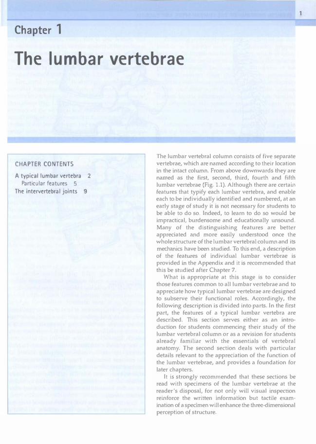
The lumbar vertebral column consists of five separate vertebrae, which are named according to their location in the intact column. From above downwards they are named as the first, second, third, fourth and fifth lumbar vertebrae (Fig. 1.1). Although there are certain features that typify each lumbar vertebra, and enable each to be individually identified and numbered, at an early stage of study it is not necessary for students to be able to do so. Indeed, to learn to do so would be impractical, burdensome and educationally unsound. Many of the distinguishing features are bettcr appreciated and more easily understood once the whole structure of the lumbar vertebral column and its mechanics have been studied. To this end, a description of the features of individual lumbar vertebrae is provided in the Appendix and it is recommended that this be studied after Chapter 7.
What is appropriate at this stage is to consider those features common to all lumbar vertebrae and to appreciate how typical lumbar vertebrae are designed to subserve their functional roles. Accordingly, the following description is divided into parts. In the first part, the features of a typical lumbar vertebra are described. This section serves either as an introduction for students commencing their study of the lumbar vertebral column or as a revision for students already familiar with the essentials of vertebral anatomy. The second section deals with particular details relevant to the appreciation of the function of the lumbar vertebrae, and provides a foundation for later chapters.
It is strongly recommended that these sections be read with specimens of the lumbar vertebrae at the reader's disposal, for not only will visual inspection reinforce the written information but tactile examination of a specimen will enhance the three-dimensional perception of structure.
1

2 CLINICAL ANATOMY OF THE LUMBAR SPINE AND SACRUM
L1
L2
L3
L4
Figure 1.1 The lumbar vertebrae and how they appear in the entire vertebral column.
A TYPICAL LUMBAR VERTEBRA
The lumbar vertebrae are irregular bones consisting of various named parts (Fig. 1.2). The anterior part of ead1 vertebra is a large block of bone called the vertebral body. The vertebra! body is more or less box shaped, with essentially flat top and bottom surfaces, a.nd slightly concave anterior and lateral surfaces. Viewed from above or below the vertebral body has a curved perimeter that is more or less kidney shaped. The posterior surface of the body is essentially flat but is obscured from thorough inspection by the posterior elements of the vertebra.
The greater part of the top and bottom surfaces of each vertebral body is smooth and perforated by tiny holes. However, the perimeter of each surface is
marked by a narrow rim of smoother, less perforated bone, which is slightly raised from the surface. This rim represents the fused ring apophysis, which is a secondary ossification centre of the vertebral body (see Ch. 12).
The posterior surface of the vertebral body is marked by one or more large holes known as the nutrient foramina. These foramina transmit the nutrient arteries of the vertebral body and the basivertebral veins (see Ch. 11). The anterolateral surfaces of the vertebra'! body are marked by sim.ilar but smaller foramina which transmjt additional intraosseous arteries.
Projecting from the back of the vertebral body are two stout pillars of bone. Each of these is called a pedicle. The pedicles attach to the upper part of the

back of the vertebral body; this is one feature that allows the superior and inferior aspects of the vertebral body to be identified. To orientate a vertebra correctly, view it from the side. That end of the posterior surface of the body to which the pedicles are more closely attached is the superior end (Fig. 1.2A, B).
The word 'pedicle' is derived from the Latin pediculus meaning little foot; the reason for this nomenclature is apparent when the vertebra is viewed from above (Fig. 1.2E). It can be seen that attached to the back of the vertebral body is an arch of bone, the neural arch, so called because it surrounds the neural elements that pass through the vertebral column. The neural arch has several parts and several projections but the pedides are those parts that look like short legs with which it appears to 'stand' on the back of the vertebral body (see Fig. 1.2E), hence the derivation from the Latin.
Projecting from each pedicle towards the midline is a sheet of bone called the lamina. The name is derived from the Latin lamina meaning leaf or plate. The two laminae meet and fuse with one another in the midline so that in a top view, the laminae look like the roof of a tent, and indeed form the so-called 'roof' of the neural arch. (Strictly speaking, there are two laminae in each vertebra, one on the left and one on the right, and the two meet posteriorly in the midline, but in some circles the term 'lamina' is used incorrectly to refer to both laminae collectively. When this is the usage, the term 'hemilamina' is used to refer to what has been described above as a true lamina.)
The full extent of the laminae is seen in a posterior view of the vertebra (Fig. 1.2D). Each lamina has slightly irregular and perhaps sharp superior edges but its lateral edge is rounded and smooth. There is no medial edge of each lamina because the two laminae blend in the midline. SilIlilarly, there is no superior lateral comer of the lamina because in this direction the lamina blends with the pedicle on that side. The inferolateral corner and inferior border of each lamina are extended and enlarged into a specialised mass of bone called the inferior articular process. A similar mass of bone extends upwards from the junction of the lamina with the pedicle, to form the superior articular process.
Each vertebra thus presents four articular processes: a right and left inferior articular process; and a right and left superior articular process. On the medial surface of each superior articular process and on the lateral surface of each inferior articular process there is a smooth area of bone which in the intact spine is covered by articular cartilage. This area is known as the articular facet of each articular process.
The lumbar vertebrae 3
Projecting posteriorly from the junction of the two laminae is a narrow blade of bone (readily gripped between the thumb and index finger), which in a side view resembles the blade of an axe. This is the spinous process, so named because in other regions of the vertebral column these processes form projections under the skin that are reminiscent of the dorsal spines of fish and other animals. The base of the spinous process blends imperceptibly with the two laminae but otherwise the spinous process presents free superior and inferior edges and a broader posterior edge.
Extending laterally from the junction of the pedicle and the lamina, on each Side, is a flat, rectangular bar of bone called the transverse process, so named because of its transverse orientation. Near its attachment to the pedicle, each transverse process bears on its posterior surface a small, irregular bony prominence called the accessory process. Accessory processes vary in form and size from a simple bump on the back of the transverse process to a more pronounced mass of bone, or a definitive pointed projection of variable length.1.2 Regardless of its actual form, the accessory process is identifiable as the only bony projection from the back of the proximal end of the transverse process. It is most evident iJ the vertebra is viewed from behind and from below (Fig. 1.2D, F).
Close inspection of the posterior edge of each of the superior articular processes reveals another small bump, distinguishable from its surroundings by its smoothness. Apparently, because this structure reminded early anatomists of the shape of breasts, it was called the mamillary process, derived from the Latin mamilla meaning little breast,1t Lies just above and slightly medial to the accessory process, and the two processes are separated by a notch, of variable depth, that may be referred to as the mamilla-accessory notch.
Reviewing the structure of the neural arch, it can be seen that each arch consists of two laminae, meeting in the midline and anchored to the back of the vertebral body by the two pedicles. Projecting posteriorly from the junction of the laminae is the spinous process, and projecting from the junction of the lamina and pedicle, on each side, are the transverse processes. The superior and inferior articular processes project from the corners of the laminae.
The other named features of the lumbar vertebrae are not bony parts but spaces and notches. Viewing a vertebra from above, it can be seen that the neural arch and the back of the vertebral body surround a space that is just about large enough to admit an examining finger. This space is the vertebral foramen, which amongst other things transmits the nervous structures enclosed by the vertebral column.

L 4 CLINICAL ANATOMY OF THE LUMBAR SPINE AND SACRUM
P---7""�
I �f t I. . SP VB ( , L·
, I, \ , --�
iaf
A. Right lateral view
TP
----if--- ial
C. Anterior view
lAP
AP
E. Top view
THE LUMBAR VERTEBRAE 3
VB SP
-,-
ial ----/--
D. Posterior view SAP
\
P
RA
F. Bottom view
Figure 1.2 The parts of a typical lumbar vertebra: AP, accessory process; jaf, inferior articular facet; lAP, inferior articular process; l, lamina; MP. mamillary process; NA, neural arch; P, pedicle; RA, ring apophysis; saf, superior articular facd; SAP, superior articular process; SP, spinous process; TP, transverse process; VB, vertebral body; IIf, vertebral foramen.

In a side view, two notches can be recognised above and below each pedicle. The superior notch is small and is bounded inferiorly by the top of the pedicle, posteriorly by the superior articular process, and anteriorly by the uppermost posterior edge of the vertebral body. The inferior notch is deeper and more pronounced. It lies behind the lower part of the vertebral body, below the lower edge of the pedicle and in front of the lamina and the inferior articular process. The difference in size of these notches can be used to correctly identify the upper and lower ends of a lumbar vertebra. The deeper, more obvious notch will always be the inferior.
Apart from providing this aid in orientating a lumbar vertebra, these notches have no intrinsic significance and have not been given a formal name. However, when consecutive lumbar vertebrae are articulated (see Fig. 1 .7), the superior and inferior notches face one another and form most of what is known as the intervertebral foramen, whose anatomy is described in further detail in Chapter 5.
Particular features
Conceptually, a lumbar vertebra may be divided into three functional components (Fig. 1.3). These are the vertebral body, the pedicles and the posterior elements consisting of the laminae and their processes. Each of these components subserves a unique function but each contributes to the integrated function of the whole vertebra.
Vertebral body
The vertebral body subserves the weight-bearing function of the vertebra and is perfectly designed for this purpose. Its flat superior and inferior surfaces are dedicated to supporting longitudinally applied loads.
Take two lumbar vertebrae and fit them together so that the inferior surface of one body rests on the superior surface of the other. Now squeeze them together, as strongly as you can. Feel how well they resist the applied longitudinal compression. The experiment can be repeated by placing the pair of vertebrae upright on a table (near the edge so that the inferior articular processes can hang down over the edge). Now press down on the upper vertebra and feel how the pair of vertebrae sustains the pressure, even up to taking your whole body weight. These experiments illustrate how the flatness of the vertebral bodies confers stability to an intervertebral joint, in the longitudinal direction. Even without intervening and other supporting structures, two articulated
The lumbar vertebrae 5
l
\ I .'
Posterior elements Vertebrat body
Pedicles
Figure 1.3 The division of a lumbar vertebra into its three functional components.
vertebrae can stably sustain immense longitudinal loads.
The load-bearing design of the vertebral body is also reflected in its internal structure. The vertebral body is not a solid block of bone but a shell of cortical bone surrounding a cancellous cavity. The advantages of this design are several. Consider the problems of a solid block of bone: although strong, a solid block of bone is heavy. (Compare the weight of five lumbar vertebrae with that of five similarly sized stones.) More significantly, although solid blocks are suitable for maintaining static loads, solid structures are not ideal for dynamic load-bearing. Their crystalline structure tends to fracture along cleavage planes when sudden forces are applied. The reason for this is that crystalline structures cannot absorb and dissipate loads suddenly applied to them. They lack resilience, and the energy goes into breaking the bonds between the constituent crystals. The manner in which vertebral bodies overcome these physical problems can be appreciated if the internal structure of the vertebral body is reconstructed.
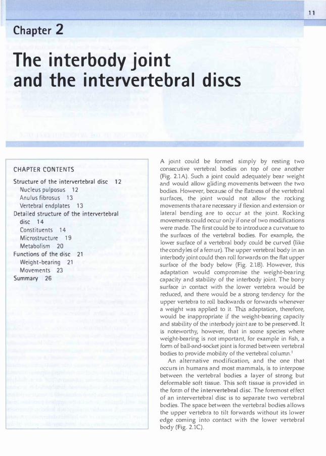
With just an outer layer of cortical bone, a vertebral body would be merely a shell (Fig. 1.4A). This shell is not strong enough to sustain longitudinal compression and would collapse like a cardboard box (Fig. I.4B). It needs to be reinforced. This can be achieved by introducing some vertical struts between the superior and inferior surfaces (Fig. 1.4C). A st� acts like a solid but narrow block of bone and,provided it is kept
6 CLINICAL ANATOMY OF THE LUMBAR SPINE AND SACRUM
straight, it can sustain j,mmense longitudinal loads. The problem with a strut, however, is that it tends to bend or bow when subjected to Cl longitudinal force. Nevertheless, a box with vertical struts, even if they bend, is still somewhat stronger than an empty box (Fig. 1.4D). The load-bearing capacity of a vertical strut can be preserved, however, if it is prevented from bowing. By introducing a series of crosswbeams, connecting the struts, the strength of a box can be further enhanced (Fig. 1.4E). Now, when a load is applied, the cross-beams hold the struts in place, preventing them from deforming and preventing the box from collapsing (Fig. 1.4F).
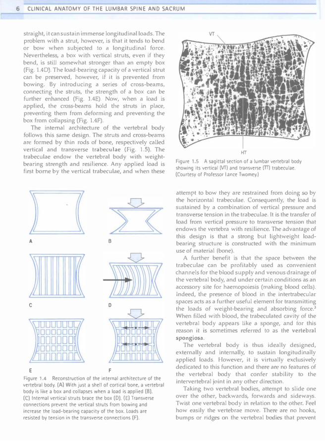
The internal archjtecture of the vertebral body follows this same design. The struts and cross-beams arc formed by thin rods of bone, respectively caUed vertical and transverse trabeculae (Fig. 1.5). The trabeculae endow the vertebral body with weightbearing strength and resil.ience. Any applied load is first borne by the vertical trabeculae, and when these
((
A B
c o
E F
Figure 1.4 Reconstruction of the internal architecture of the vertebral body. (Al With just a shell of cortical bone. a vertebra! body is like a box and collapses when a load is applied (B). (C) Internal vertical struts brace the box (D). (E) Transverse connections prevent the vertical struts from bowing and increase the load-bearing capacity of the box. loads are resisted by tension in the transverse connections (F).
HT
Figure 1.5 A sagittal section of a lumbar vertebral body showing its vertical (VT) and transverse (IT) trabeculae. (Courtesy of Professor lance Twomey.)
attempt to bow they are restrained from doing so by the horizontal trabeculae. Consequently, the load is sustained by a combination of vertical pressure and transverse tension in the trabecuJae. It is the transfer of load from vertical pressure to transverse tension that endows the vertebra with resilience. The advantage of this design is that a strong but lightweighl loadbearing structure is constructed with the minimum use of material (bone).
A further benefit is that the space between the trabeculae can be profitably used as convenient channels for the blood supply and venous drainage of the vertebral body, and under certain conditions as an accessory site for haemopoiesis (making blood cells). Indeed, the presence of blood in the intertrabecular spaces acts as a further useful element for transmitting the loads of weight-bearing and absorbing force.3 When filled with blood, the trabeculated cavity of the vertebral body appears like a sponge, and for this reason it is sometimes referred to as the vertebral spongiosa.
The vertebral body is thus ideally designed, externally and intenlally, to sustain longitudinally applied loads. However, it is virtually exclusively dedicated to this function and there are no features of the vertebral body that confer stability to the intervertebral jOint in any other direction.
Taking two vertebral bodies, attempt to slide one over the other, backwards, forwards and sideways. Twist one vertebral body in relation to the other. Feel how easily the vertebrae move. There are no hooks, bumps or ridges on the vertebral bodies that prevent

gliding or twisting movements between them. Lacking such features, the vertebral bodies are totally dependent on other structures for stability in the horizontal plane, and foremost amongst these are the posterior elements of the vertebrae.
Posterior elements
The posterior elements of a vertebra are the laminae, the articular processes and the spinous processes (see Fig. 1.3). The transverse processes are not customarily regarded as part of the posterior elements because they have a slightly different embryological origin (see Ch. 12), but for present purposes they can be considered together with them.
Collectively, the posterior elements form a very irregular mass of bone, with various bars of bone projecting in all directions. This is because the various posterior elements are specially adapted to receive the different forces that act on a vertebra.
The inferior articular processes fonn obvious hooks that project downwards. In the intact lumbar vertebral column, these processes will lock into the superior articular processes of the vertebra below, forming synovial joints whose principal function is to provide a locking mechanism that resists forward sliding and twisting of the vertebral bodies. This action can be illustrated by the following experiment.
Place two consecutive vertebrae together so that their bodies rest on one another and the inferior articular processes of the upper vertebra lock behind the superior articular processes of the lower vertebra. Slide the upper vertebra forwards and feel how the locked articular processes resist this movement. Next, holding the vertebral bodies slightly pressed together, attempt to twist them. Note how one of the inferior articular processes rams into its apposed superior articular process, and realise that further twisting can occur only if the vertebral bodies slide off one another.
The spinous, transverse, accessory and mamillary processes provide areas for muscle attachments. Moreover, the longer processes (the transverse and spinous processes) form substantial levers, which enhance the action of the muscles that attach to them. The details of the attachments of muscles are described in Chapter 9 but it is worth noting at this stage that every muscle that acts on the lumbar vertebral column is attached somewhere on the posterior elements. Only the crura of the diaphragm and parts of the psoas muscles attach to the vertebral bodies but these muscles have no primary action on the lumbar vertebrae. Every other muscle attaches to either the transverse, spinous, accessory or mamillary processes or laminae. This
The lumbar vertebrae 7
emphasises how all the muscular forces acting on a vertebra are delivered first to the posterior elements.
Traditionally, the function of the laminae has been dismissed simply as a protective one. The laminae are described as forming a bony protective covering over the neural contents of the vertebral canal. While this is a worthwhile function, it is not an essential function as demonstrated by patients who suffer no ill-effects to their nervous systems when laminae have been removed at operation. In such patients, it is only under unusual circumstances that the neural contents of the vertebral canal can be injured.
The laminae serve a more significant, but subtle and therefore overlooked, functlon. Amongst the posterior elements, they are centrally placed, and the various forces that act on the spinous and articular processes are ultimately transmitted to the laminae. By inspecting a vertebra, note how any force acting on the spinous process or the inferior articular processes must next be transmitted to the laminae. This concept is most important for appreciating how the stability of the lumbar spine can be compromised when a lamina is destroyed or weakened by disease, injury or surgery. Without a lamina to transmit the forces from the spinous and inferior articular processes, a vertebral body would be denied the benefit of these forces that either execute movement or provide stability.
That part of the lamina that intervenes between the superior and inferior articular process on each side is given a special name, the pars interarticuiaris, meaning 'interarticular part'. The pars interarticularis runs obliquely from the lateral border of the lamina to its upper border. The biomechanical significance of the pars interarticularis is that it lies at the junction of the vertically orientated lamina and the horizontally projecting pedicle. It is therefore subjected to considerable bending forces as the forces transmitted by the lamina undergo a change of direction into the pedicle. To withstand these forces, the cortical bone in the pars interarticularis is generally thicker than anywhere else in the lamina:' However, in some individuals the cortical bone is insufficiently thick to withstand excessive or sudden forces applied to the pars interarticularis,o; and such individuals are susceptible to fatigue fractures, or stress fractures to the pars interarticu laris. 5-7
Pedides
Customarily, the pedicles are parts of the lumbar vertebrae that are simply named, and no particular function is ascribed to them. However, as with the laminae, their function is so subtle (or so obviOUS) that it is overlooked or neglected.

8 CLINICAL ANATOMY OF THE LUMBAR SPINE AND SACRUM
The pedides are the only connect jon between the posterior elements and the vertebral bodies. As described above, the bodies are designed for weightbearing but cannot resist sliding or twisting movements, while the posterior elements are adapted to receive various forces, the articular processes locking against rotations and forward slides, and the other processes receiving the action of muscles. All forces sustained by any of the posterior elements are ultimately channelled towards the pedicles, which then transmit the benefit of these forces to the vertebral bodies.
The pedicles transmit both tension and bending forces. If a vertebral body slides forwards, the inferior articular processes of that vertebra wiH lock against the superior articular processes of the next lower vertebra and resist the slide. This resistance is transmitted to the vertebral body as tension along the pedicles. Bending forces are exerted by the muscles attached to the posterior elements. Conspicuously (see Ch. 9), all the muscles that act on a lumbar vertebra pull downwards. Therefore, muscular action is transmitted to the vertebral body through the pedicles, which act as levers and thereby are subjected to a certain amount of bending.
The pedicles are superbly designed to sustain these forces. Externally, they are stout pillars of bone. in crosssection they are found to be cylinders with thick walls. This structure enables them to resist bending in any direction. When a pedicle is bent downwards its upper wall is tensed while its lower wall is compressed. Similarly, if it is bent medially its outer wall is tensed while its inner wall is compressed. Through such combinations of tension and compression aJong opposite walls, the pedicle can resist bending forces applied to it. In accordance with engineering principles, a beam when bent resists deformation with its peripheral surfaces; towards its centre, forces reduce to zero. Consequently, there is no need for bone in the centre of a pedicle, which explains why the pedicle is hollow but surrounded by thick walls of bone.
Internal structure
The trabecular structure of the vertebral body (Fig. 1 .6A) extends into the posterior elements. Bundles of trabeculae sweep out of the vertebral body, through the pedicles, and into the articular processes, laminae and transverse processes. They reinforce these processes like internal buttresses, and are orientated to resist the forces and deformations that the processes habitually sustajn.8 From the superior and inferior surfaces of the vertebral body, longitudinal trabeculae sweep into the inferior and articular processes
(Fig. 1.6B). From opposite sides of the vertebral body, horizontal trabeculae sweep into the laminae and transverse processes (Fig. 1.6C). Within each process the extrinsic trabeculae from the vertebral body intersect with intrinsic trabeculae from the opposite
A
B
C
Figure 1.6 Internal architecture of a lumbar vertebra. (A) A midsagittal section showing the vertical and horizontal trabeculae of the vtrtebral body, and the trabttulae of the spinous prOttSS. (B) A lateral saginal section showing the trabroJlae passing through the pedicle into the articular processes. (e) A transvtrse section showing the trabeculae swetping out of the vertebral body into the laminae and transvtrse prOCtlStS. (Based on Gallais and Japiot-)

surface of the process. The trabeculae of the spinous process are difficult to discern in detail, but seem to be anchored in the lamina and along the borders of the process.8
THE INTERVERTEBRAL JOINTS
When any two consecutive lumbar vertebrae are articulated, they fonn three joints. One is formed between the two vertebral bodies. The other two are formed by the articulation of the superior articular process of one vertebra with the inferior articular processes of the vertebra above (Fig. 1.7). The nomenclature of these joints is varied, irregular and confusing.
The joints between the articular processes have an 'official' name. Each is known as a zygapophysial joint ' Individual zygapophysial joints can be specified by using the adjectives 'left' or 'right' and the numbers of the vertebrae involved in the formation of the joint. For example, the left L3-4 zygapophysial joint refers to the joint on the left, formed between the third and fourth lumbar vertebrae.
The term 'zygapophysial', is derived from the Greek words apophysis, meaning outgrowth, and zygos, meaning yoke or bridge. The term 'zygapophysis', therefore, means 'a bridging outgrowth' and refers to any articular process. The derivation relates to how, when two articulated vertebrae are viewed from the side, the articuJar processes appear to arch towards one another to form a bridge between the two vertebrae.
Other names used for the zygapophysial joints are 'apophysial' joints and 'facet' joints. 'Apophysial' predominates in the British literature and is simply a contraction of 'zygapophysial', which is the correct term. 'Facet' joint is a lazy and deplorable term. It is popularised in the American literature, probably because it is conveniently short but it carries no formal endorsement and is essentially ambiguous. The term stems from the fact that the joints are formed by the articular facets of the articular processes but the term 'facet' applies to any such structure in the skeleton. Every small joint has a facet. For example, in the thoracic spine, there are facets not only for the zygapophysial joints but also for the costovertebral joints and the costotransverse joints. Facets are not restricted to zygapophysial articular processes and strictly the term 'facet' joint does not imply only zygapophysial joints.
Because the zygapophysial joints are located posteriorly, they are also known as the posterior intervertebral jOints. This nomenclature implies that
Jomt between articular processes
� . .
The lumbar vertebrae
A . Lateral VIew
B. Postenor vtew
Joint between vertebral bodies
' . ,�r I,
\ 1
Figur� 1 .7 Th� joints b�tw��n two lumbar v�rt�bra�.
9
J

1 0 CLINICAL ANATOMY O F THE LUMBAR SPINE AND SACRUM
the joint between the vertebral bodies is known as the anterior intervertebral joint (Table 1.1) but this latter term is rarely, if ever, used. In fact, there is no formal name for the joint between the vertebral bodies, and difficulties arise if one seeks to refer to this joint. The term ' interhody joint' is descriptive and usable but carries no formal endorsement and is not conventional. The term 'anterior intervertebral joint' is equally descriptive but is too unwieldy for convenient usage.
The only formal technical term for the joints between the vertebral bodies is the classification to which the joints belong. These joints are symphyses, and so can be called intervertebral symphyses'J or intervertebral amphiarthroses, but again these are unwieldy terms. Moreover, if this system of nomenclature were adopted, to maintain consistency the zygapophysial joints would have to be known as the intervertebral diarthroses (see Table 1.1), which would compound the complexity of nomenclature of the intervertebral joints.
In this text, the terms 'zygapophysial joint' and 'interbody joint' will be used, and the detaiJs of the structure of these joints is described in the following chapters.
References
.I. Le Double AF. Traite des Variations de la Colonnc Vertebral de I'Homme. Paris: Vigot; 1912: 271-274.
2. Louyot P. Propos sur Ie tubercle accessoire de J'apophysc costiforme lombaire. J Radiol Electrol 1976; 57,905-906.
3. White AA, Panjabi MM. Clinical Biomechanics of the Spine. Philadelphia: Lippincott; 1978.
4. Krenz J, Troup JOC. The structure of the pars interarticularis of the lower lumbar vertebrae and its relation to the etiology of spondylolysis. J Bone Joint Surg 1973; 55B,735-74I.
5. Cyron BM, f {utton We. Variations in the amount and distribution of cortical bone across the partes
Table 1 . 1 Systematic nomenclature of the intervertebral joints
Joints between articular process
Joints between vertebral bodies
--------
Zygapophysial joints (No equivalent term)
Posterior int�rv�rt�bral joints
Int�rvertebral diarthroses
Spelling
(No equival�nt t�rm) Int�rbody joints
Anterior int�rv�rt�bral joints Interv�rt�bral
amphiarthroses or intervertebral symphyses
Some editors of journals and books have deferred to dictionaries that spell the word 'zygapophysial' as 'zygapophyseal'. It has been argued that this fashion is not consistent with the derivation of the word.1O
The English word is derived from the singula" zygapophysis. Consequently the adjective 'zygapophysial' is also derived from the singular and is spelled with an 'i'. This is the interpretation adopted by the lntemational Anatontical Nomenclature Committee in the latest edition of the N011lilrn Allntom;cn.�
i,nterarticulares of LS. A predispoSing factor in spondylOlysis? Spine 1979; 4:163--167.
6. I lutton we. Stott JRR Cyron 8M. Is spondylolysiS a fatigue fracture? Spine 19n; 2:202-209.
7. Troup JOG. The etiology of spondylolysis. Orthup CHn North Am 1977; 8,57-64.
8. Gallais M, Japiot M. Architectu.re interieure des vertebres (statique et physiologie de la colonne vcrtebrale). Rev Chirurgie 1925; 63:687-708.
9. Nomina Anatomica, 6th eeln. Edinburgh: Churchill Livingstone; 1989.
10. Bogduk N. On the speLling of zygapophysial and of anulu5. Spine 1994; J9:1n1.
Chapter 2
The interbody joint and the intervertebral discs
CHAPTER CONTENTS
Structure of the intervertebral disc 12
Nucleus pulposus 12
Anulus fibrosus 13
Vertebral endplates 13
Detailed structure of the intervertebral disc 14
Constituents 14
Microstructure 19
Metabolism 20
Functions of the disc 21
Weight-bearing 21
Movements 23
Summary 26
J
A joint could be formed simply by resting two consecutive vertebral bodies on top of one another (Fig. 2.1A). Such a joint could adequately bear weight and would allow gUding movements between the two bodies. However, because of the Hatness of the vertebral surfaces, the joint would not allow the rocking movements that are necess.:,ry if flexion and extension or lateral bending are to occur at the joint. Rocking movements could occur only if one of two modifications were made. The first could be to introduce a curvature to the surfaces of the vertebral bodies. For example, the lower surface of a vertebral body could be curved (like the condyles of a femur). The upper vertebral body in an interbody joint could then roll forwards on the flat upper surface of the body below (Fig. 2.16). However, this adaptation would compromise the weight-bearing capacity and stability of the interbody joint. The bony surface in contact with the lower vertebra would be reduced, and there would be a strong tendency for the upper vertebra to roll backwards or forwards whenever a weight was applied to it. This adaptation, therefore, would be inappropriate if the weight-bearing capacity and stability of the interbody joint are to be preserved. It is noteworthy, however, that in some species where weight-bearing is not important, for example in fish, a foml of baU-and-socket joint is formed between vertebral bodies to provide mobility of the vertebral column. I
An alternative modification, and the one that occurs in humans and most mammals, is to interpose between the vertebral bodies a layer of strong but deformable soft tissue. This soft tissue is provided in the form of the intervertebral disc. The foremost effect of an intervertebral disc is to separate two vertebral bodies. The space between the vertebral bodies allows the upper vertebra to tilt forwards without its lower edge coming into contact with the lower vertebral body (Fig. 2.1C).
11

1 2 CLINICAL ANATOMY OF THE LUMBAR SPINE AND SACRUM
A
B
c
Figure 2.1 Possible designs of an interbody joint. (A) The vertebral bodies rest directly on one another. (B) Adding a curvature to the bottom of a vertebra allows rocking movements to occur. (el Interposing soft tissue between the vertebral bodies separates them and allows rocking movements to occur.
The consequent biomechanical requirements of an intervertebral disc are threefold. in the fi,rst instance, it must be strong enough to sustain weight, Le. transfer the load from one vertebra to the next, without collapsing (being squashed), Secondly, without unduly compromising its strength, the disc must be deformable to accommodate the rocking movements of the vertebrae. Thirdly, it must be sufficiently strong so as not to be injured during movement. The structure of the intervertebral discs, therefore, should be studied with these requirements in mind.
STRUCTURE OF THE INTERVERTEBRAL DISC
Each intervertebral disc consists of two basic components: a central nucleus pulposus surrounded by a peripheral anulus fibrosus. AHhough the nucleus pulposus is quite distinct in the centre of the disc, and the anulus fibrosus is distinct at its periphery, there is no clear boundary betvveen the nucleus and the anulus within the disc, Rather, the peripheral parts of the nucleus pulposus merge with the deeper parts of the anulus fibrosus.
A third component of the intervertebral disc comprises two layers of cartilage which cover the top and bottom aspects of each disc. Each is called a vertebral endplate (Fig, 2.2), The vertebral endplales separate the disc from the adjacent vertebra] bodies, and it is debatable whether the endplates are strictly components of the disc or whether they actually belong to the respective vertebral bodies. The interpretation used here is that the end plates are components of the intervertebral disc.
Nucleus pulposus
In typical, healthy, intervertebral discs of young adults, the nucleus pulposus is a semifluid mass of mucoid material (with the consistency, more or less, of toothpaste). Embryologically, the nucleus pulposus is a remnant of the notochord (see Ch, 12), Histologically, it consists of a few cartilage cells and some irregularly arranged collagen fibres, dispersed in a medium of semHluid ground substance (see below). Biomechanjcally, the fluid nature of the nucleus pulposus allows it to be deformed under pressure, but as a fluid its volume cannot be compressed. if subjected to pressure from any direction, the nucleus will attempt to deform and will thereby transmit the applied pressure in all directions. A suitable analogy is a balloon filled with water. Compression of the balloon deforms it; pressu. re in the balloon rises and stretches the walls of the balloon in all directions.

AF AF
YEP
Coronal sectIon
Postenor
AF AF
Anterior
Transverse section Figurr: 2.2 The basic structure of a lumbar intervertebral disc. The disc consists of a nucleus pulposus (NP) surrounded by an anulus fibrosus (AF). both sandwiched between two cartilaginous vertebral end plates (VEP).
Anulus fibrosus
The anulus fibrosus consists of collagen fibres arranged in a highly ordered pattern. Foremost, the collagen fibres are arranged in between 10 and 20 sheets2.3 called lamellae (from the Latin lamella meaning little leaf). The lamellae are arranged in concentric rings which surround the nucleus pulposus (Figs 2.2 and 2.3). The lamellae are thicker towards the centre of the disc;4 they are thick in the anterior and lateral portions of the anulus but posteriorly they are finer and more tightly packed. Consequently the posterior portion of the anulus fibrosus is thinner than the rest of the anulus.2.S,6
Within each lamella, the collagen fibres lie parallel to one another, passing from the vertebra above to the
The interbody joint and the intervertebral discs 13
Figure 2.3 The detailed structure of the anulus fibrosus. Collagen fibres are arranged in 10-20 concentric circumferential lamellae. The orientation of fibres alternates in successive lamellae but their orientation with respect to the: vertical (0) is always the same and measures about 65'.
vertebra below. The orientation of all the fibres in any given lameUa is therefore the same and measures about 65-70' from the vertical?)! However, while the angle is the same, the direction of this inclination alternates with each lamella. Viewed from the front, the fibres in one lamella may be orientated 65 to the right but those in the next deeper lamella will be orientated 65' to the left. The fibres in the next lamella will again Ue 65 to the right, and so on (see Fig. 2.3). Every second lamella, therefore, has exactly the same orientation. These figures, however, constitute an average orientation of fibres in the mid-portion of any lamella. Near their attachments, fibres may be orientated more steeply or less steeply with respect to the sagittal plane'
The implication of the classic description of the anulus fibrosus is that the lamellae of the anulus form complete rings around the circumference of the disc. However, this proves not to be the case. In any given quadrant of the anulus, some 40% of the lamellae are incomplete, and in the posterolateral quadrant some 50% are incomplete:1 An incomplete lamella is one that ceases to pass around the circumference of the disc. Around its terminal edge the lamellae superficial and deep to it either approximate or fuse (Fig. 2.4). Incomplete lamellae seem to be more frequent in the middle portion of the anulus,"
Vertebral endplates
Each vertebral end plate is a layer of cartilage about 0.6-1 mm thick10-11 that covers the area on the

14 CLINICAL ANATOMY OF THE LUMBAR SPINE AND SACRUM
Figure 2.4 The appearance of incomplete lamellae of the anulu5 fibro5U5. At 'a', two subconsecutive lamellae fuse around the terminal end of an incomplete lamella. At 'b', two subconsecutive lamellae become apposed, without fUSing,
around the end of another incomplde lamella.
vertebral body encircled by the ring apophysis. The two end plates of each disc, therefore, cover the nucleus pu)posus in its entirety, but peripherally they fail to cover the entire extent of the anulus fibrosus (Fig. 2.5). Histologically, the end plate consists of both hyaline cartilage and fibrocartilage. Hyaline cartilage occurs towards the vertebral body and is most evident in neonatal and young discs (see eh. 12). Fibrocartilage occurs towards the nucleus pulposus; in older discs the end plates are virtually entirely fibrocartilage (see Ch. 13). The fibrocartilage is formed by the insertion into the end plate of collagen fibres of the anulus fibrosus.b
The collagen fibres of the inner lamellae of the anulus enter the end plate and swing centrally within it.J·IlI" By tracing these fibres along their entire length it can be seen that the nucleus pulposus is enclosed by a sphere of collagen fibres, more or less like a capsule. Anteriorly, posteriorly and laterally, this capsule is
Anulus fibrosus
Figure 2.S Detailed structure of the vertebral end plate. The collagen fibres of the inner two-thirds of the anulus fibrosus sweep around into the vertebral end plate, forming its fibrocartilaginous component The peripheral fibres of the anulus are anchored into the bone of the ring apophysis.
apparent as the innermost lamellae of the anulus fibrosus, but superiorly and inferiorly the 'capsule' is absorbed into the vertebral endplatcs (see Fig. 2.5).
Where the endplate is deficient, over the ring apophysis, the collagen fibres of the most superficial lamellae of the anulus insert directly into the bone of the vertebral body (see Fig. 2.5)14 In their original form, in younger discs, these fibres attach to the vertebral end plate which fully covers the vertebral bodies in the developing lumbar spine, but they are absorbed secondarily into bone " .. · hen the ring apophysis ossifies (see Ch. 12).
Because of the attachment of the anulus fibrosus to the vertebral end plates, the endplates arc strongly bound to the intervertebral disc. In contrast, the endplates are only weakly attached to the vertebral bodiesl.1.1 .. and can be wholly torn from the vertebral bodies in certain forms of spinal trauma}<; It is for this and other morphological reasons that the endpJates are regarded as constituents of the intervertebral disc rather than as parts of the vertebral bodies.l(l·l1 .D.lt>-11l
Over some of the surface area of the vertebral end plate (about 10%) the subchondral bone of the vertebral body is deficient and pockets of the marrow cavity touch the surface of the end plate or penetrate a short distance into it.IUII These pockets facilitate the diffusion of nutrients from blood vessels in the marrow space and are important for the nutrition of the end plate and intervertebral disc (see Ch. 11).
DETAILED STRUCTURE OF THE INTERVERTEBRAL DISC
Constituents
Gfycosominogfycons
As a class of chemicals glycosaminoglycans (GAGs) are present in most forms of connective tissue. They are found in skin, bone, cartilage, tendon, heart valves, arterial walls, synovial fluid and the aqueous humour of the eye. Chemically, they are long chains of polysaccharides, each chain consisting of a repeated sequence of hvo molecules called the repeating unit (Fig. 2.6) .">1 These repeating units consist of a sugar molecule and a sugar molecule with an amine attached, and the nomenclature 'glycosaminoglycan' is designed to reflect the sequence of 'sugar amine-sugar- .. .' in their structure.
The length of individual GAGs varies but is characteristically about 20 repeating units.21 Each different GAG is characterised by the particular molecules that make up its repc.1ting unit. The GAGs predominantly found in human intervertebral discs are chondroitin-

Repeating unrt
Figure 2.6 Tht: molecular structure of a mucopolysaccharide. The molecule consists of a chain of sugar molecules, cach being a six-carbon ring (hexose). Every second sugar is a hexose-amine (HA). The chain is a repdition of identical pairs of hexose, hexose-amine units, called the repeating unit.
6-sulphate, chondroitin+sulphate, keratan sulphate and hyaluronic acid,22.2l The stntctures of the repeating units of these molecules are shown in Fig. 2.7.
Proteoglycons
Proteoglycans are very large molecules consisting of many GAGs linked to proteins. They occur in two basic forms: proteoglycan units and proteoglycan aggregates. Proteoglycan units are formed when several GAGs are linked to a polypeptide chain known as a core protein (Fig. 2.8),22.2'\ A single core protein may carry as few as six or as many as 60 polysaccharide chains.21 The GAGs are joined to the core protein by covalent bonds involving special sugar molecules.22.23 Proteoglycan aggregates are formed when several proteoglycan units are linked to a chain of hyaluronic acid. A single hyaluronic chain may bind 20 to 100 proteoglycan units." The linkage between the proteoglycan units and the hyaluronic acid is stabilised by a relatively small mass of protein known as the link protein (see Fig. 2.8).22
I The cardinal proteoglycan of the intervertebral 'disc resembles that of articular cartilage and is known as aggrecan.25 Its detailed structure is shown in Figure 2.9. Its core protein exhibits three coiled regions called globular domains (G1, G2 and G3) and two relatively straight regions called extended domains (El and E2l.2f! GAGs are bound principally and most densely to the El domain. Chondroitin sulphate binds to the terminal three-quarters or so of the E2 domain (Le. towards the carboxyl end, or C-terminal, of the core protein).21-24.26 Keratan sulphate binds predominantly towards the N-terminal of the E2 domain but also occurs amongst the chondroitin chains.22-2ub.27 Some keratan sulphate chains also bind to the El domain.
The N-terminal of the core protein bears the Gl domain, which is folded like an immunoglobulin; a similar structure is exhibited by the link protein. It is
The interbody joint and the intervertebral discs 1 5
Hyaluronic Acid
COOH CH,oH
�: 61, 4 'l-H---l 61,3
GlucuroniC acid
Chondroitin 4 Sulphate
Glucuronic acid
ChondroItin 6 Sulphate
COOH
N. acetyl gtucosamine
N. acetyl glucosamine 4 sulphate
CH,OSO,H
U�'I----?t<I---NH--Il1
Glucuronic acid
Keratan Sulphate
CH,OH
Galactose
N. acetyl glucosamine 6 sulphate
CH,OSO,H
tK'I-----l'� H NHCOCH, N. acetyl glucosamlne
6 sulphate
Figure 2.7 The chemical structure of the repeating units of the glycosaminoglycans.
these coiled structures that bind hyaluronic acid and allow the aggrecan molecules to aggregate.26 The Gl domain does not assume its structure until after a newly synthesised molecule of aggrecan has left the cell that produces it.2S This ensures that aggregation occurs only in the extracellular matrix.
Details of the G3 domain are still being determined but it seems to have a carbohydrate-binding capacity,

'6 CLINICAL ANATOMY OF THE LUMBAR SPINE AND SACRUM
GAGs
CS==t--
KS • '" HyaluronIC acid unk prote.n
Core protein
Proleog/ycan units
Proteogtycan aggregates Stable Figure 2.8 The structure of proteoglycans. Proteoglycan units are formed by many GAGs linked to a core: protein. Keratan sulphate chains (KS) tcnd to occur closer to the head of the core protein. longer chains of chondroitin sulphate ICS) are attached along the entire length of the corc protein. Proteoglycan aggregates are formed when several protein units arc linked to a chain of hyaluronic acid. Their linkaqe is stabilised by a link protein.
which might enable aggrecan molecules to attach to cell surfaces. The functions of the G2 domain remain unclear. Functionally, the E2 domain is the important one, for it is this region that is responsible for the water-binding properties of the molecule.
Large proteoglycans thai aggregate with hyaluronic acid are characteristic of hyaline cartilage and they occur in immature intervertebral discs.2J They are rich in chondroitin sulphate, carrying about 100 of these chains, each with an average molecular weight of about 20000. They carry 3()...6() keratan sulphate chains, each with a molecular weight of 4000 to 8000." Large and moderately sized proteoglycans that do not aggregate with hyaluronic acid are the major proteoglycans that occur in the mature nucleus pulpOSUS.2.1
In vivo, proteoglycan units and aggregates are convoluted to form complex, three-dimensional molecules, like large and small tangles of cotton wool (Fig. 2.10). PhysicochemicaUy, these molecules have the property of attracting and retaining water (compare this with the water-absorbing properties of a ball of cotton wool). The volume enclosed by a proteoglycan molecule, and into which it can attract water, is known as its domain.21
The water-binding capacity of a proteoglycan molecule is partially a property of its size and physical shape, but the main force that holds water to the molecule sterns from the ionic, carboxyl (COOH) and sulphate (SO,) radicals of the GAG chains (see Fig. 2.7). These radicals attract water electrically, and

Figure 2.9 The structure of aggre:can. The: core: protein exhibits three globular domains (G 1, G2 and G3J and two extended domains (Et and E2). The: E2 domain binds keratan sulphate (KSJ and chondroitin sulphate (CS). The Gt domain is coiled like an immunoglobulin (lg), as is the link protein, and is the site of the aggrecan molecule that binds with hyaluronic add.
Gl
Igl"d
/ Hyaluronic Acid
\
El
The interbody joint and the intervertebral discs 1 7
G2
KS domain
E2
CS domain
Water trapping
G3
�rotein
GAGs
Core protein
Figure 2.10 A sketch of a coiled proteoglycan unit, illustrating how the ionic radicals on its GAGs attract water into its 'domain',
the water�binding capacity of a proteoglycan can be shown to be proportional to the density of these ionic radicals in its structure. 1n this respect, sulphated GAGs attract water more strongly than other mucopolysaccharides of simiJar size that lack sulphate radicals. Furthermore, it is readily apparent that because the chondroitin sulphates have both sulphate and carboxyl radicals in their repeating units (see Fig. 2.7), they will have twice the water-binding capacity of keratan sulphate, which, although carrying
a sulphate radical, lacks a carboxyl radical. The waterbinding capacity of any proteoglycan will therefore be largely dependent on the concentration of chondroitin sulphate within its structure.2'�
Collagen
Fundamentally, collagen consists of strands of protein molecules. The fundamental unit of collagen is the tropocollagen molecule, which itself consists of three polypeptide chains wound around one another in a helical fashion and held together end to end by hydrogen bonds (Fig. 2.11). Collagen is formed when many tropocollagen molecuJes are arrayed end-on and side by side. When only a few tropocollagen chains are arrayed side by side, the structure formed is known as a small col1agen fibril. When the structure is made thicker, by the addition of further layers of tropocollagen chains, it becomes a large fibril. The aggregation of several large fibrils forms a collagen fibre. The tropocollagen chains within a collagen fibre are held together, side by side, by covalent bonds involving a molecule of hydroxylysine (see Fig. 2.11).2&-»
There are 11 types of collagen found in connective tissue.Jl Each type is genetically determined and differs in the chemical nature of the polypeptide chains that form the tropocollagen molecules found in the collagen fibre and in the microstructure of the fibre. The different types of collagen are denoted by Roman numerals as types I, ll, rn up to type Xl.
Types I, 11, lll, V and XI exhibit the typical triple helical structure described above. Types IV and vn are long-chain molecules that bear a globular extension at one end and whose triple helix is interrupted periodically by non-helical segments. Types VI, VU!,

18 CLINICAL ANATOMY OF THE LUMBAR SPINE AND SACRUM
A Collagen libnl
O.1�-O.5�
1
T
B. M�rofibnl
Bond between ChalllS
C. Tropocollagen
15A
SpliCIng PoIypephde cha"s Figur� 2.11 The structure of collagen. A collagen fibril (A) is made up of several microfibrils (8). Each microfibril consists of several chains of tropocollagen (e) held together side to side by covalent bonds involving hydroxylysine molecules ( ... J. Tropocollagen consists of three polyptptide chains wound around one another in a helical fashion. Tropocollagen chains are formed by the peptide chains in constcutive mole:cul� splicing and being held together by electrostatic bonds between their ends.
IX and X are much shorter molecules with interrupted or uniform helical segments that bear globular extensions at one or both ends.)1
Type I, 11 and III molecules form most of the collagen fibres of the body; types I and 11 are typical of musculoskeletal tissues. Their distribution is shown in Table 2.1. Type I collagen is essentially tensile in nature and is found in tissues that are typically subjected to tension and compression. Type II collagen is more elastic in nature and is typically found in tissues habitually exposed to pressure.
Type III collagen is typical of the dermis, blood vessels and synovium. Type IV collagen occurs only
Table 2.1 Genetic types of collagen and their distribution in connective tissues
Type Distribution
Skin, bone. tendon, meniscus, dentine, anulus fibrosus II Cartilage, vitreous humour, nucleus pulposus III Dermis, heart, blood vessels, synovium IV Basement membrane V Co-distributed with typt I VI Blood vessels, viscera, muscle VII VIII
Ectodermal basement membranes Desetmet's membrane
IX Cartilage, vitreous humour X Epiphysial plates XI Co-distributed with type II
in basement membranes; type VII is found in basement membranes of ectodermal origin; and type VIII is found in Descemet's membrane of the cornea; type X has been found only in epiphysial plates; type VI is characteristically found in blood vessels, viscera and muscles while type IX occurs in cartilage.)1
The principal types of collagen found in the intervertebral disc are types I and II. Other types of collagen occur in much lesser amounts. Type V collagen is regularly associated with type I collagen and is co-distributed with it, but its concentration is only about 3% of that of type I. Similarly, type XI coexists with type I I but at only about 3% of its concentration.)) Type IX collagen occurs in disc� at about 2% of the concentration of type II; its function appears to be to link proteoglycans to collagen fibres and to control the size of type II fibrils." Small amOWlts of type VI collagen occur in both the nucleus pulposus and anuius fibrosus, and traces of type III coUagen occur within the nucleus pulposus and inner anulus fibrosus; these collagens are located in the immediate pericellular regions of the matrix,n but their functions are still unknown.)1
80th type I and type 11 collagen are present in the anulus fibrosus but type I is the predominant form.2S�_\'l-)7 Type IJ collagen predominates in the nucleus pulposus and is located between cells in the interterritorial matrix . .l2 Type I collagen is absent from the central portions of the nucleus or is present only in small amoWlts. This difference in distribution within the intervertebral disc correlates with the different biomechanical roles of the anulus fibrosus and the nucleus pulposus. From a knowledge of the biochemistry of the collagen in the intervertebral disc, it can be anticipated that the nucleus pulposus, with

only type II collagen, will be involved more in processes involving pressure, while the anulus fibrosus, containing both type I and type II collagen, will be involved in both tension-related and prcssurcrelated processes.
An important property of collagen and proteoglycans is that they can bind together. The binding involves both electrostatic and covalent bonds,20,UU7-W and these bonds contribute to the strength of structures whose principal constituents arc proteoglycans and collagen. Bonds are formed directly between proteo
'glycans and type I and type II collagen, or indirectly through type IX collagen.
Other proteogfycans
Like articular cartilage, the intervertebral disc contains small quantities of two small proteoglycans - decorin and biglycan41- whose core proteins bear chains of the glycosaminoglycan derma tan sulphate, one chain in the case of decorin, two in the case of biglycan. These proteoglycans interact with collagen, fibronectin and growth factors in the matrix of the disc, and are therefore critical factors in the homeostasis and repair of the matrix.oi2
Enzymes
The intervertebral disc, like articular cartilage, contains proteolytic enzymes.�1--l'i These enzymes are known as matrix metalloproteinases (MMPs). The three main types are MMP-1 (or collagenase), MMP-2 (or gelatinase) and MMP-3 (or stromelysin). Collagenase and gelatinase have very selective substrates. Collagenase can cleave type U collagen; geiatinase cannot but it can cleave the fragments of type 11 collagen produced by collagenase. Strome lysin is the most destructive of the enzymes. It can cleave types 11, XI and IX collagen as well as fibronectin but it also has an aggressive action on proteoglycans, cleaving aggrecan molecules between their El and G2 domains.
Under normal circumstances, these enzymes function to remove old components of the matrix, allowing them to be replaced with fresh components. The enzymes are secreted as inactive forms, which are subsequently activated by agents such as plasmin, and are inhibited by proteins known as tissue inhibitors of metalloproteinases, which prevent excessive enzyme activity ... J, .... If the balance between activators and inhibitors is disturbed, excessive action of stromelysin may result in degradation of the matrix, at a rate that normal repair processes cannot keep up with.
The interbody joint and the intervertebral discs 19
Microstructure
Nucleus pufposus
The nucleus puJposus is 70--900/1'1 waterI7,JO,4tt-49 although the exact proportion varies with age (see Ch. 13). Proteoglycans are the next major component, and they constitute about 65% of the dry weight of the nucleus:,".47The water of the nucleus is contained within the domains of these proteoglycans. Only about 25% of the proteoglycans occur in an aggregated form.24 The majority are in the fonn of freely dispersed proteoglycan units that lack a functional binding site that would enable them to aggregate with hyaluronic acid.2J
About two-thirds of the proteoglycan aggregates in the nucleus pulposus are smaller than those typically found in articular cartilage.27 Each consists of about 8 to 18 proteoglycan units closely spaced on a short chain of hyaluronic acid.v
I Interspersed through the proteoglycan medium are thin fibrils of type II collagen, which serve to hold proteoglycan aggregates together.'i051 The mixture of proteoglycan units, agg-regates and collagen fibres within the nucleus pulposus is referred to collectively as the matrix of the nucleus. ) Collagen constitutes 15-20% of the dry weight of the nucleus22.46 and the remainder of the nucleus consists of some elastic fibres and small quantities of various other proteins known as non-collagenous proteins.JO,.w·.w.,4ij,5253 These include the link proteins of the proteoglycans37,44 and other proteins involved in stabilising the structure of large collagen fibrilsJ7 and other components of the nuclear matrix;44 however, the function of many of these non-collagenous proteins remains unknown .....
Embedded in the proteoglycan medium of the nucleus are cartilage cells (chondrocytes), and in the newborn there are also some remnant cells of the notochord (see Ch. 12).'" The cartilage cells are located predomjnantly in the regions of the vertebral end plates and are responsible for the synthesis of the pro teDglycans and collagen of the nucleus pulpOSUS.19.1'" The type III collagen that occurs in the intervertebral disc is characteristically located around the cells of the nucleus pulposus and the inner anulus fibrosus.1J
It is the presence of water, in large volumes, that endows the nucleus pulposus with its fluid properties, and the proteoglycans and collagen fibrils account for its 'thickness' and viscosity ('stickiness').
Anufus fibrosus
Water is also the principal structural component of the anulus fibrosus, amounting to 60-70% of its weight.J7�",,4h-49 Collagen makes up 50-60% of the dry

20 CLINICAL ANATOMY OF THE LUMBAR SPINE AND SACRUM
weight of the anuius,)(l,)),4h52 and the tight spaces between collagen fibres and between separate lamellae are filled with a proteoglycan gel that binds the collagen fibres and lamellae together to prevent them from buckling or fraying.24 Proteoglycans make up about 20% of the dry weight of the anulus," and it is this gel that binds the water of the anulus. About 50-60% of the proteoglycans of the anulus fibrosus are aggregated, principally in the form of large aggregates.27 The concentration of proteoglycans and water is somewhat greater in the anterior anulus than in the posterior anuius, and in both regions increases from the outer to the inner anulus; conversely, there is progressively less collagen from the outcr to the inner anulus.54
Interspersed among the collagen fibres and lamellae arc chondrocytes and fibroblasts that are responsible for synthesising the collagen and the proteoglycan gel of the anulus fibrosus. The fibroblasts are located predominantly towards the periphery of the anulus while the chondrocytes occur in the deeper anulus, towards the nucleus.111,N
From a biochemical standpoint, it can be seen that the nucleus pulposus and anulus fibrosus are similar. Both consist of water, collagen and proteoglycans. The differences lie only in the relative concentrations of these components, and in the particular type of collagen that predominates in each part . The nucleus pulposus consists predominantly of proteoglycans and water, with some type II collagen. The anulus fibrosus also consists of proteoglycans and a large amount of water but is essentially 'thickened' by a high concentration of collagen, type II collagen being found throughout the anulus and type I concentrated largely in the outer anulus.32
The anulus fibrosus also contains a notable quantity of elastic fibres.ss-� Elastic fibres constitute about 10% of the anulus fibrosus and are arranged circularly, obliquely and vertically within the lamelJae of the anulus.� They appear to be concentrated towards the attachment sites of the anulus with the vertebral end plate. 'W
Vertebral endplates
The chemical structure of the vertebral end plate resembles and parallels that of the rest of the disc. It consists of proteoglycans and collagen fibres, with cartilage cells aligned along the collagen fibres." It resembles the rest of the disc by having a higher concentration of water and proteoglycans and a lower collagen content towards its central region, which covers the nucleus pulposus, with a reciprocal pattern over the anulus fibrosus. Across the thickness of the
endplate the tissue nearer bone contains more collagen while that nearer the nucleus pulposus contains more proteoglycans and water.lI This resemblance to the rest of the disc means that at a chemical level the endplate does not constitute an additional barrier to diffusion. Small molecules pass through an essentially uniform, chemical environment to move from the vertebral body to the centre of the disc.
Metabolism
The proteoglycans and collagen of the intervertebral disc are synthesised and maintained by the chrondrocytes and fibroblasts of the nucleus and anulus (Fig. 2.12). In fetal and newborn discs, cells in the nucleus exhibit far greater synthetic activity than those in the anulus, but in mature discs the greatest
I activity occurs in the mid-portion of the anulus, there being progressively less activity exhibited towards the outer anulus and towards the nucleus.flO
Once synthesised and delivered out of the cell, the proteoglycans aggregate and bind to the collagen fibres, thereby establishing the solid phase of the matrix. Water is then retained in the domains of the proteoglycans. This matrix, however, undergoes a slow turnover. Systematically, old protcoglycans and collagen are constantly removed and replaced. Removal is achieved by the metalloproteinases. Collagenase degrades type II collagen whereas stromelysin degrades both collagen and proteoglycans (see Fig. 2.12).
All these activities require the cells to be metabolically active; they require oxygen, glucose, the substrates for the products they produce, and cofactors involved in their production. However, the disc essentially lacks a blood supply and the cells therefore rely on diffusion for their nutrition (see eh. 11). Because of this low blood supply, the oxygen concentrations in the centre of a disc are only 2-5% of those at its periphery/I' and the cells of the disc must rely on anaerobic metabolism. As a result, the cells produce large amounts of lactic acid, which makes the environment of the disc acidic"I.II2 with a pH in the range of 6.9-7.1 .'1."
The metabolism of cells in the nucleus is very sensitive to changes in pH. They are maximally active in pH ranges of 6.9-7.2, but below 6.8 their activity falls steeply. Below 6.3 their activity is only about 15�lo maximum.b2
The status of the matrix relies on a critical balance between the synthetic and degradative achvities of the cells, and this balance can be disturbed by any number of factors such as impaired nutrition, inflammatory mediators or changes in pH. Seemingly trivial changes

Degradation
Proslromeiysln
The interbody joint and the intervertebral discs 2 1
Synthesis Figure 2.12 Metabolism of the matrix of an intervertebral disc. Chrondrocytes synthesise collagen and proteoglycans, which form the matrix and retain water. They also produce enzymes that can degrade the collagens and proteoglycans. The enzymes, in turn, are controlled by activators such as plasmin, and inhibitors such as tissue inhibitors of mdalloproteinases (TlMP).
Progelahnase ----\ Procoliagenase f·
+ ¢ PlasmIn
----.-. I Collagen
TIMP
PrOleogiycans
1 Collagenase ------'*----- * W/V'IWIIVW'A
Gelatlnase --------* *_
Siromeiysin -------E:----- *
r TIMP
in these factors can lead to major changes in the status of the matrix.
FUNCTIONS OF THE DISC
The principal functions of the disc are to allow movement between vertebral bodies and to transmit loads from one vertebral body to the next. Having reviewed the detailed structure of the intervertebral disc, it is possible to appreciate how this structure accommodates these functions.
Weight-bearing
Both the nucleus pulposus and the anulus fibrosus are involved in weight-bearing. The anulus participates in two ways: independently; and in concert with the nucleus pulposus. Its independent role will be considered first.
Although the anuJu5 is 60-70% water, its densely packed collagen lamellae make it a turgid, relatively stiff body. In a sense, the collagen lamellae endow the anulus with 'bulk'. As long as the lamellae remain healthy and intact and are held together by their proteoglycan gel, the anulus will resist buckling and
*
will be capable of sustaining weight in a passive way, simply on the basis of its bulk.
A suitable analogy for this phenomenon is a thick book like a telephone directory. If the book is wrapped into a semkylindrical form and stood on its end, its weight-bearing capacity can be tested and appreciated. So long as the pages of the book do not buckle, the book standing on end can sustain large weights.
The compression stiffness of the anulus fibrosus is essentially uniform across the thickness of the anuJus, although there is a tendency for the inner anuJus to be less stiff than the middle and outer anuli.54 The compression stiffness of the anulus correlates inversely but weakly with its water content but not with its proteoglycan content.S-!
It has been shown experimentally that, under briefly applied loads, a disc with its nucleus removed maintains virtually the same axial load-bearing capacity as an intact disc,6J These observations demonstrate that the anulus fibrosus is able to act as a passive space filler and to act alone in transmitting weights from one vertebra to the next. The disc does not necessarily need a nucleus pulposus to do this -the anulus alone can be sufficient.
The liability of an isolated anulus fibrosus, however, is that if subjected to prolonged weight-bearing, it will

22 CLINICAL ANATOMY OF THE LUMBAR SPINE AND SACRUM
tend to deform, i.e. it will be slowly squashed by any sustained weight. Sustained pressure will buckle the collagen lamellae and water will be squeezed out of the anulus. Both processes will lessen the height of the anulus. The binding of the collagen by proteoglycan gel will not be enough to prevent this prolonged deformation. Some form of additional bracing mechanism is required. This is provided by the nucleus pulposus.
As a ball of fluid, the nucleus pulposus may be deformed but its volume cannot be compressed. Thus, A when a weight is applied to a nucleus from above it tends to reduce the height of the nucleus, and the nucleus tries to expand radially, i.e. outwards towards the anulus fibrosus. This radial expansion exerts a pressure on the anulus that tends to stretch its collagen lamellae outwards; however, the tensile properties of the collagen resist this stretch, and the collagen lamellae of the anulus oppose the outward pressure exerted on them by the nucleus (Fig. 2.13).
For any given load applied to the disc, an equilibrium will eventuaUy be attained in which the radial pressure exerted by the nucleus will be exactly balanced by the tension developed in the anulus. Ln a healthy disc with intact collagen lamellae, this equilibrium is attained with minimum radial expansion of the nucleus. The anulus fibrosus is normally SO thick and strong that, during weight-bearing, it resists any tendency for the disc to bulge radially. Application of a 40 kg load to an intervertebral disc causes only 1 nun of vertical compression and only 0.5 mm of radial expansion of the disc.M
The other direction in which the nucleus exerts its pressure is towards the vertebral endplates (see Fig. 2.13) but because the end plates are applied to the vertebral bodies they too will resist deformation. The situation that arises, therefore, is that when subjected B
to a load, the nucleus attempts to deform but it is prevented from doing so. Radially it is constrained by the anulus fibrosus, and upwards and downwards it is constrained by the vertebral endplates and vertebral bodies. All that the nucleus can do is exert its raised pressure against the anulus and the endplates.
Figure 2.13 The mechanism of weight transmission in an intervertebral disc. (A) Compression raises the pressure in the nucleus pulposus. This is exerted radially onto the anulus fibrosus and the tension in the anulus rises. (Bl The tension in the anulus is exerted on the nucleus preventing it from expanding radially. Nuclear pressure is then exerted on the vertebral end plates. (Cl Weight is borne, in part. by the anulus fibrosus and by the nucleus pulposus. The radial pressure in the nucleus braces the anulus. and the pressure on the endplates transmits the load from one vertebra to the next.
c

This achieves two things. The pressure exerted on the end plates serves to transmit part of the applied load from one vertebra to the next, thereby lessening the load borne by the anulus fibrosus. Secondly, the radial pressure on the anulus fibrosus braces it and prevents the antllus from buckJing. This aids the anulus in its own capacity to transmit weight.
The advantage of the cooperative action of the nucleus and the antllus is that the disc can slIstain loads that othenvise might tend to buckle an antllus fibrosus acting alone,l.\'i The essence of the combined mechanism is the fluid property of the nucleus pulposus. The waler content of the nucleus makes the disc a turgid body that resists compression, and the water content of the nucleus is therefore of critical importance to the disc. Because the water content of the nucleus is, in tum, a function of its proteoglycan content, the normal mechanics of the disc will ultimately depend on a normal proteoglycan content of the nucleus pulposus. Any change in the proteoglycan and water content of the nucleus will inevitably alter the mechanical properties of the disc (see Ch. 13).
A further property of the disc is its capacity to absorb and store energy. As the nucleus tries to expand radially, energy is used to stretch the collagen or the anulus fibrosus. The collagen fibres are elastic and stretch like springs, and as such they store the energy that went into stretching them. If the load applied to the disc is released, the elastic recoil of the collagen fibres causes the energy stored in them to be exerted back onto the nucleus plilposus, where it is used to restore any deformation that the nucleus may have undergone. This combined action of the nucleus and anulus endows the disc with a resilience or ·springiness'.
In essence, the fluid nature of the nucleus enables it to rranslate vertically applied pressure into circumferential tension in the anulus. In a static situation this tension balances the pressure in the nucleus, but if the applied load is released the tension is used to restore any deformation of the disc that may have occurred. BiochenUcally, this mechanical property of the disc is due to the presence of proteoglycans and water in the nucleus, and the tensile properties of the type [ collagen in the anuJus fibrosus.
In a more global sense, the resilience of the intervertebral disc enables it to act as a shock absorber. If a force is rapidly applied to a disc, it will be diverted momentarily into stretching the anulus fibrosus. This brief diversion attenuates the speed at which a force is transmitted from one vertebra to the next; the size of the force is not lessened. Ultimately, it is fully transmitted to the next vertebra. However, by temporarily diverting the force into the anuilis fibrosus, a disc can protect its underlying vertebra by slowing the rate at
Tho interbody joint and the intervertebral discs 23
which the applied force is transmitted to that vertebra.
Movements
It is somewhat artificial to consider the movements of an interbody joint, as in-vivo movement of any l umbar vertebra always involves movement not only at the interbody joint but at the zygapophysial joints as well. However, in order to establish principles relevant to the appreciation of the role played by interbody joints in the movements of the intact lumbar spine, it is worth while to consider the interbody joints separately, as if they were capable of independent movement.
If unrestricted by any of the posterior elements of the vertebrae, two vertebral bodies united by an intervertebral disc can move in virtually any direction. In weight-bearing they can press together. Conversely, if distracted, they can separate. They can slide forwards, backwards or sideways; they can rock forwards, backwards and sideways, or in any direction in between; and they can twist. Deformation of the disc accommodates all of these movements but at the same time the disc confers varying degrees of stabiJjty to the interbody joint during these movements. The mechanics of the disc during compression (weightbearing) has already been described but a study of each of the other movements of the interbody joint iJlustrates how well the disc is designed to also accommodate and stabilise these movements.
During distraction, all points on one vertebral body move an equal distance perpendicularly from the upper surface of the other vertebral body (Fig. 2.14). Consequently, the a ttachments of every collagen fibre in the anuJus fibrosus are separated an equal distance. Every fibre is therefore strained and every fibre in the anulus resists distraction. Because of the density of collagen fibres in the anulus fibrosus, distraction is strongly resisted by the anulus. The capacity of the discs in this regard is illustrated by how well they sustain the load of the trunk and lower limbs in activities like hanging by the hands. Hanging by the hands, however, is not a common activity of daily living, and vertebral distraction is not a particularly common event. On the other hand, distraction is induced clinically, in the form of traction. A further description of the mechanics of traction, however, is deferred until Chapter 8, when it is considered in the context of the whole lumbar spine.
In pure sliding movements of the interbody joint, all points on one vertebra move an equal distance parallel to the upper surface of the next vertebra (Fig. 2.15). This movement is resisted by the anulus fibrosus but the fibres of the anulus act differently

24 CLINICAL ANATOMY OF THE LUMBAR SPINE AND SACRUM
\ I
D
Figure 2.14 Distraction of the interbody joint Separation of the vertebral bodies increases the height of the intervertebral disc (.6.h), and all the collagen fibres in the anulus fibrosus are lengthened and tensed, regardless of their orientation.
according to their location within the anulus and in relation to the direction of movement. in forward sliding, the fibres at the sides of the disc Lie in a plane more or less parallel to the direction of movement and run obliquely between the vertebraJ bodies but in opposite directions in each successive lamella. Consequently, during forward sliding, only half of the fibres in the lateral Mulus will be strained, for only half of the fibres have their points of attachment separated by the movement. The other hal! have their points approximated (see Fig. 2.15). Therefore, only half the fibres in the lateral anuJus contribute to resisting forward sliding.
Fibres in the anterior and posterior anuli also contribute resistance but not to as great an extent as the lateral fibres. Although the movement separates the points of attachment of aU the fibres in the anterior and posterior anuli, the separation is not in the principal direction of orientation of the fibres. These fibres run either to the left or to the right, whereas the movement is forwards. The effect of forward sliding is simply to incline the planes of the lamellae in the anterior and posterior anuli anteriorly. Under these circumstances, the degree of stretch imparted to the
Figure 2.15 Sliding movements of an interbody joint. Those fibres of the anulus that are orientated in the direction of movement have their points of attachment separated, and therefore they are stretched. Fibres in every second lamella of the anulus have their points of attachment approximated, and these fibres are relaxed.
anterior and posterior anuli is less than that imparted to the lateral anulus, whose fibres are stretched principally longitudinally.
Bending or rocking movements involve the lowering of one end of the vertebral body and the raising of the opposite end. This necessarily causes distortion of the anuius fibrosus and the nucleus pulposus, and it is the fluid content of the nucleus and anulus that permits this deformation. In forward bending, the anterior end of the vertebral body lowers, while the posterior end rises. Consequently, the anterior anulus will be compressed and will tend to buckl ....... (Fig. 2.16). The nucleus pulposus will also be compressed but mainly anteriorly. The elevation of the posterior end of the vertebral body relieves pressure on the nucleus pulposus posteriorly but at the same time stretches the posterior anulus.
The anterior anulus buckles because it is directly and selectively compressed by the tilting vertebral body, and because it is not braced internally by the nucleus pulposus. Although the nucleus is compressed anteriorly. it is relieved posteriorly and is able to deform posteriorly.

o
Figure 2.1 6 Rocking movement of the interbody joint. Rocking cauStS compression of the anulus fibrosus in the direction of movement, and stretching of the anulus on the opposite side. NP, nucleus pulposus.
Mathematical analyses indicate that if the disc is not otherwise loaded (e.g. also bearing weight) there should be no rise in nuclear pressure during bending of an interbody joint as the volume of the nucleus puJposus remains unchanged,8 Experimental studies, however, show that in cadaveric discs, 5- of bending is associated with a rise in nuclear pressure of about 0.7 kPa cm-2•7n This rise is the same regardless of the load carried by the disc, therefore the relative increase in disc pressure caused by bending decreases as greater extemal I""ds are appHed. The increase in disc pressure amounts to about 22% of the total disc pressure for loads of 2 kPa em-' but is only 5% for loads of 10 kPa em .z.'"
The large increases in disc pressure seen in vivo during bending of the lumbar spine are not intrinSically due to the bending but are the result of the additional compressive loads applied to the discs by the action of the back muscles that control the bend ing (see Ch. 9).
When an interbody joint bends, the anterior compression deforms the nucleus pulposus, which tries to 'escape' the compression by moving backwards. If at the same time a load is applied to the disc, nuclear pressure will rise and this will be exerted on the posterior anulus which is already stretched by the separation of the vertebral bodies posteriorly. A normal
The interbody joint and the intervertebral discs 2 5
anulus will adequately resist this combination of tension and pressure but because the posterior anulus is the thinnest portion of the entire anulus, its capacity to resist is readily compromised.
Previous injury, or erosion as a result of disc disease, may weaken some of the lamellae of the posterior anulus, and the remaining lamellae may be insufficient to resist the tension and posterior pressure that occurs in loaded forward bending. Consequently, the pressure of the nucleus may rupture the remaining lamellae, and extrusion, or herniation, of the nucleus pulposus may result (see Ch. 15). The resistance to this type of injury is proportional to the density of collagen fibres in the posterior anulus. Thicker anuli afford more protection than thinner ones but the shape of the posterior anulus also plays a role.
Discs that are concave posteriorly have a greater cross-sectional area of anulus posteriorly than do discs with an elliptical shape, even if the anulus is the same thickness (Fig. 2.17). Thus, concave discs are better designed than posteriorly convex discs to withstand forward bending and injury during this movement,l� and this difference has a bearing on the pattern of injuries seen in intervertebral discs (see Ch. 15).
During twisting movements of the interbody joint, all points on the lower surface of one vertebra will move circumferentialLy in the direction of the twist; this has a unique effect on the anulus fibrosus. Because of the alternating direction of orientation of the collagen fibres in the anulus, only those fibres inclined in the direction of movement will have their points of attachment separated. Those inclined in the opposite direction will have their points of attachment approximated (Fig. 2.18). Thus, at any time, the anulus resists twisting movements with only half of its complement of collagen fibres. Half of the number of lamellae in the anulus will be stretched, while the other half will be relaxed. This is one of the reasons why twisting movements of an interbody joint are the most likely to injure the anulus (see Chs 8 and 15).
Figure 2.17 Discs that are concave posteriorly have a greater portion of anulus fibrosus located posteriorly. Therefore, concave discs have more anulus available to resist the posterior stretch that occurs in flexion.

26 CLINICAL ANATOMY OF THE LUMBAR SPINE AND SACRUM
Figure 2.18 Twisting movements of the interbody joint Thost fibrts of the anulus that are orientated in the direction of the twist have their points of attachment stpaf'3ted. and are therefore stretched. Fibres in evt.ry stcond lamella of the anulus have their points of attachment approximated and these fibres are relaxed.
S U M MARY
From the preceding accounts, it is evident that the different components of an intervertebral disc act in different ways, both independently and cooperatively, during the various functions of the disc. The nucleus pulposus is designed to sustain and transmit pressure. It is principally involved in weightbearing, when it transmits loads and braces the anu)us fibrosus. During bending it deforms in a passive manner, unless the joint is additionally loaded, in which case its weight·bearing function is superimposed
References
I Kingsley JS. The vertebrate skeleton. London: Murray, 1925: 22.
2. Annstrong JR. Lumbar disc lesions, 3rd edn. Edinburgh: Churchill livingstone, 1965: 13.
3. Taylor JR The development and adult structure of lumbar intervertebral discs. J Man Med 1990;
5:43-47.
on the mechanics of bending. The nucleus pulposus does not participate in the other movements of the interbody joint. These are resisted by the anulus fibrosus.
In all movements, the anulus fibrosus acts like a ligament to restrain movements and to stabilise the joint to some degree. Whenever the attachments of individual collagen fibres are separated, these fibres will be stretched and will resist the movement. All fibres resist distraction, and all are involved in weightbearing. In other movements, the participation of individual collagen fibres will depend on their orientation with respect to the movement. In this way, the alternating oblique orientation of the collagen fibres of the anulus fibrosus optimises the capacity of the anulus to restrain various movements in various directions.
If the fibres of the anulus were arranged perpendicular to the vertebral bodies, they would be optimally orientated to resist distraction. However, they would afford virtually no resistance to sliding movemenls of the joint. The advantage of the oblique orientation is that each fibre can offer a component of resistance both verticaUy and horizontally, and therefore the anulus fibrosus can participate in resisting movemenls in all directions. The degree of obliquity governs the extent to which a fibre resists horizontal movement, versus vertical movement, and it can be shown mathematically that the orientation of 65 is optimal for the various strains that an anuJus is caJled upon to sustain.1f A steeper orientation would enhance resistance to distraction but would compromise resistance to sliding and twisting. Conversely, a flatter orientation would enhance resistance to twisting, but would compromise resistance to distraction and bending. The aJtemation of the direction of fibres in alternate lameUae of the anulus fibrosus is integral to the capacity of the disc to resist twisting. Half of the lamellae are dedicated to resisting twisting to the right, the other half resist twisting to the left. For a more detailed analysis of the mechanics of the anulus fibrosus, the reader is referred to the papers of Hickey and Huki.ns/� Hukins,11 Brobergn and Farfan and Cracovetsky.73
-l Marchand F, Ahmed AM. Invt-stigation of the laminate structure of lumbar disc anulus fibrosus. Spine 1990;
15:402--110.
5. Jayson MIV, Barks JS. Structural changes in the intervertebral disc. Ann Rheum Dis 1973; 32:10-15.
6. Peacock A. Observations on the pre--natal development of the intervertebral disc in man. J Anal 1951; 85:260-274.

7. Hickey OS. Hukins DWL. X-ray diffraction studies of the arrangement of collagen fibres in human fetal intervertebral disc. J Anal 1980; 131 :81-90.
8. Hickey OS. Hukins OWL. Relation between the structure of the annulus fibrosus and the function and failure of the intervertebral disc. Spine 1980; 5:100-116.
9. Tsuji H, Hirano N. Ohshima H et al. Structural variation of the anterior and posterior anulus fibrosus in the development of human lumbar intervertebral disc: a risk factor for intervertebral disc rupture. Spine 1993; 18:2Q.i-210.
10. Eyring EJ. The biochemistry and physiology of the intervertebral disk. Clio Orthop 1969; 67:16-28.
1 1 Roberts Sf Menage J, Urban PC. Biochemical and structural properties of the cartilage end-plate and its relation to the intervertebral disc. Spine 1989; 14·166-174
12. 5.,unders JB de CM, Inman vr. Pathology of the intervertebral disk. Arch Surg 1940; 4():380-416.
13. Coventry MB, Ghormley RK, Kemohan JW. The inten'ertebral diSC: its mjcroscopic anatomy and patholog)·. Part I. Anatomy, development and phYSiology. J Bone Joint Surg 1945; 27:105-112.
14. Inoue 1-1. Three-dimensional architecture of lumbar intervertebral discs. Spine 1981; 6:138-146.
IS. MacNab 1 B.1ckache. Baltimore: Williams & Wilkins; 1977: 4-7
16. Coventry MB. Anatomy of the inten'ertebral disk. C1in Orthop 1969; 67:9-15.
17. Schmorl G, Junghanns II. The human spine in health and disease, 2nd American ron. New York: Grune & Stratton; 1971: 18.
18. Taylor JR. Growth of the human intervertebral discs and vertebral bodies. J Anat 1975; 120:49-68.
19. Maroudas A, Nachemson A, Stockwell R et al. Some factors involved in the nutrition of the intervertebral disc. J An.1 1975; 120: 11:H30.
20. Comper WD, Laurent TC. Physiological function of connective tissue polysaccharides. Physiol Rev 1978; 58:255-315.
21 White A. Handler P. Smith EL. Principles of Biochemjstry, 4th eeln. New York: McCraw-Hili; 1968: 871-886.
22. Bushell GR, Ghosh P, Taylor TKF et al. Proteoglycan chemistry of the inten·ertebral disks. Clin Orthop 1977; 129:115-123.
23. Mcl:)evitt CA. Proteoglycans of the intervertebral disc. In: Ghosh P, eel. The Biology of the Inten'ertebral Disc, Vol. 1. Boca Raton: CRC Press; 1988: Ch.6, 151-170.
24. Urban J, Maroudas A. The chemistry of the intervertebral disc in relation to its physiological function. Clin Rheum Dis 1980; 6:51-76.
25. Johnstone B, Bayliss MT. The large protooglycans of the human intervertebral disc. Spine 1995; 20:674-68-1.
26. Hardingham T, Bayliss M. Proteoglycans of articular cartilage: changes in aging and in joint disease. Semin Arthritis Rheum 1990; 205:12-33.
27. Buckwalter jA, Pedrini-MilJe A, Pedrini V et al. Prott..'Oglycans of human infant intervertebral discs. J Bone Joint Surg 1985; 67A:284-294.
The interbody joint and the intervertebral discs 27
28. Bailey Al, Herbert CM, Jayson MIV. Collagen of the intervertebral disc. In: Jayson MIV, ed. The Lumbar Spine and Backache. New York: Grune & Stratton; 1976: Ch. 12, 327-340.
29. Ilerhert CM, Lindberg KA, Jayson MJV et al. Changes in the collagen of human intervertebral discs during ageing and degenerative disc disease. J Mol Meet 1975; 1:79-91.
30. Naylor A, Shental R. Biochemical aspects of intervertebral discs in ageing and d isease. In: Jayson MIV, ed. The Lumbar Spine and Backache. New York: Grune & Stratton; 1976: Ch. 4, 317-326.
31. Eyre D. Collagens of the disc. [n: Ghosh P, ed. The Biology of the Intervertebral Disc, Vol. I. Boca Raton: CRC Press; 1988: 171-188.
32. Roberts 5, Menage j, Duance V et al. Collagen types around the cells of the intervertebral disc and cartilage end plate: an immunolocalization study. Spine 1991; 16: 1 030-1038.
33. Adams P, Eyre DR. Muir H. Biochemical aspects of de\'elopment and ageing of human lumbar intervertebral discs. Rheumatol Rehab 1977; 16:22-29.
34. Brickley-Parsons D, Glimcher MJ. Is the chemistry of collagen in inten'ertebral discs an expression of Wolff's law? A study of the human lumbar spine. Spine 1984; 9:141>-163.
35. Eyre D, Muir H. Type I and Type II collagen in intervertebral disk. Interchanging radial distribution in annulus fibrosus. Biochem J 1976; 157:267-270.
36. Eyre D, Muir H. Quantitative analysis of types I and 11 collagen in human intervertebral discs at various ages. Biochimica et Biophysica Acta 1977; 492:2�2.
37. Ghosh P, Bushell GK, Taylor TFK et al. Collagen, elastin, and non-coUagenous protein of the intervertebral disk. C1in Or1hop 1977; 129:123-132.
38. Meachim G, Comah MS. Fine structure of juvenile human nucleus pulposus. J Anat 1970; 107:337-350.
39. Pearson CH, Happey F, Naylor A et al. Collagens and associated glycoproteins in the human intervertebral disc. Ann Rheum Dis 19n; 31 :45-53.
40. Stevens FS, Jackson OS, Broady K. Protein of the human inten1ertebral disc. The association of collagen with a protein fraction having an unusual amino acid composition. Biochim Biophys Acta 1968; 160:435-446.
41 . Johnstone B, Markopoulous M, Neame P et at. Identification and characterization of glycanated and non-glycanated forms of biglycan and decorin in the human intervertebral disc. Biochem J 1993; 292:661--666.
42. Kuettner KE. Cartilage integrity and homeostasis. In: Klippel JI-I. Dieppe PA, eds. Rheumatology. SI Louis: Mosby; 1994: 7.6.1-7.6.16.
43. Kanemoto M, Hukuda S, Komiya Y et al. Immunohistochemjcal study of matrix metalloproteinase-3 and tissue inhibitor oC metaUoproteinase-l in human intervertebral discs. Spine 1996; 21:1-8.
44. Melrose J, Ghosh P. The noncollagenous proteins of the inten'ertebral disc. In: Ghosh p. ed. The Biology of the Inten'ertebral Disc, Vol. I. Boca Raton: eRC Press; 1988: Ch. 8, 189-237.

28 CLINICAL ANATOMY OF THE LUMBAR SPINE AND SACRUM
45. Sedowfia KA, Tomlinson IW, Weiss }6 et al. Collagenolytic enzyme systems in human intervertebral disc. Spine 1982; 7,213-222.
46. Beard HK, Stevens RL. Biochemical changes in the intervertebral disc. In: Jayson MJV, ed. The Lumbar Spine and Backache, 2nd edn. London: Pitman; 1980:
407-436.
47. Gower WE, Pedrini V. Age-related variation in protein polysaccharides from human nucleus pulposus, annulus fibrosus and costal cartilage. J Bone Joint SUTg 1%9;
51A,II5-t-1162.
48. Naylor A. Intervertebral disc prolapse and degeneration. The biochemical and biophysical approach. Spine 1976;
1 ,108-114.
49. ruschel J. Der Wassergehalt nannaler und degenerierter Zwi.schenwirbelscheiben. BeitT path Anal 1930;
8·U23-130. SO. Inoue H, Takeda T. Three-dimensional observation of
collagen framework of lumbar intervertebral discs. Acta Orthop Scandinav 1975; 46:949-956.
51. Sylven B, Paulson 5, Hirsch C et al. Biophysical and physiological investigations on cartilage and other mesenchymal tissues. J Bone Joint Surg 1951;
33A,333-340.
52. Dickson IR, Happey F, Pearson CH et al. Variations in the protein components of human intervertebral disk with age. Nature 1%7; 215:52-53.
53. Taylor TKF, LiHle K. tntercellular matrix of the intervertebral disk in ageing and in prolapse. Nature 1965; 208,384-386.
54. Best BA, GuiJak F, Setton LA et al. Compressive mechanical properties of the human anulus fibrosus and their relationship to biochemical composition. Spine 1994; 1nI2-221 .
55. Buckwalter JA, Cooper RR, Maynard JA. Elastic fibers in human intervertebral disks. J Bone Joint Surg 1976;
58A,73-76.
56. Hickey OS, Hukins OWL. Collagen fibril diameters and elastic fibres in the annulus fibrosus of human fetal intervertebral disc. J Anat 1981; 133:351-357.
57. Hickey OS, Hukins OWL. Aging changes in the macromolecular organization of the intervertebral disc. An X-ray diffraction and electron microscopic study. Spine 1982; 7,234-242.
58. Johnson EF, Berryman H, Mitchell R et a1 Elastic fibres in the anulus fibrosus of the human lumbar
intervertebral disc. A preliminary �port. J Anal 1985;
143,57-63.
59. Johnson EF, Chetty K, Moo� 1M et al. The distribution and arrangement of elastic fibres in the IVO of the adult human. J Anat 1982; 135:301-309.
60. Bayliss MT, Johnstone B, O'Brien JP. Proteoglycan synthesiS in the human intervertebral disc: variation with age, region and pathology. Spine 1988; 13:9n-981.
61. HoLm 5, Maroudas A, Urban JPG et al. Nutrition of the intervertebral disc: solute transport and metabolism. Connect Tass Res 1981; 8:101-119.
62. Ohshima H, Urban JPG. The effect of lactate and pH on proteoglycan and protein synthesis rales in the intervertebral disc. Spine 1992; 17: 1079-1082.
63. Markolf KL, Morris JM. The structural components of the intervertebral disc. J Bone Joint Surg 1974;
56A,675-687.
64. Hirsch C, Nachemson A. New observations on mechanical behaviour of lumbar discs. Acta Orthop Scandinav 1954; 23:254-283.
65. Roaf R. A study of the mechaniCS of spinal i.njurles. J Bone Joint Surg 1960; 42B,81�23.
66. Brown T, Hansen RJ, Yorra AJ. Some mechanical tests on the lumbosacral spine with particular reference to the intervertebral discs. J Bone Joint Surg 1957;
39A,1135-1164.
67. Shah 15. Structure, morphology and mechanics of the lumbar spine. In: Jayson MIV, eel. The Lumbar Spine and Backache, 2nd eeln. London: Pitman; 1980: Ch. 13,
359-405.
68. Shah JS, Hampson WGJ, Jayson MIV The distribution of surface strain in the cadaveric lumbar spine. J Bone Joint Surg 1978; 608,246-251.
69. White AA. Panjabi MM_ Clinical Biomechanics of the Spine. Philadelphia: Lippincott; 1978.
70. Nachemson A. The influence of spinal movements on the lumbar intradiscal pressure and on the tensile stresses in the annulus fibrosus. Acta Orthop Scandinav 1963; 33,183-207.
71. Hukins OWL. Disc structure and function. In: Ghosh P, ed. The Biology of the Intervertebral Disc, Vol. I. Boca Raton, CRC Press; 1968, Ch. 1 , 1-37.
n. Broberg KB. On the mechanical behaviour of intervertebral discs. Spine 1983; 8:151-165.
73. Farfan HF, Gracovetsky S. The nature of instability. Spine 1984; 9,nl ... 719.

Chapter 3
The zygapophysial joints -detailed structure
CHAPTER CONTENTS
Articular facets 29
Articular cartilage 33 Capsule 33 Synovium 34 Intra-articular structures 34
The lumbar zygapophysial joints are formed by the articuJation of the inferior articular processes of one lumbar vertebra with the superior articular processes of the next vertebra. The joints exhibit the features typical of -(ynovial joints. The articula,r facets are covered by articular cartilage, and a synovial membrane bridges the margins of the articular cartilages of the two facets in each joint. Surrounding the synovial membrane is a joint capsule which attaches to the articular processes a short distance beyond the margin of the articular cartilage (Fig. 3.1).
ARTICULAR FACETS
The articular facets of the lumbar vertebrae are ovoid in shape, measuring some 16 mm in height and 14 mm in width, and having a surface area of about 160 mm2. The facets of upper vertebrae are slightly smaller than these values indicate; those of the lower vertebrae are slightly smaller.'
Viewed from behind (see Fig. 3.1), the articular facets of the lumbar zygapophysial joints appear as straight surfaces, suggesting that the joints are planar. However, viewed from above (Fig. 3.2), the articular facets vary both in the shape of their articular surfaces and in the general direction they face. Both of these features have significant ram.ifications in the biomechanics of these joints and, consequently, of the lumbar spine, and should be understood and appreciated.
In the transverse plane, the articular facets may be flat or planar, or may be curved to varying extents (Fig. 3.3)' The curvature may be little different from a nat plane (Fig. 3.30) or may be more pronounced, with the superior articular facets depicting a C shape (Fig. 3.3E) or a J shape (Fig. 3.3F). The relative
29

30 CLINICAL ANATOMY OF THE LUMBAR SPINE AND SACRUM
Figure 3.1 A posterior view of the l3-4 zygapophysial jOints. On the Idt. the capsule of the joint (el is intact. On the right, the posterior capsule has been resected to reveal the joint cavity, the articular cartilages (AC) and the line of attachment of the joint capsule (--I. The upper jOint capsule (e) attaches further from the articular margin than the posterior capsule.
Figurr: 3.2 A top vir:w of an l3-4 zygapophysial joint shOWing how th( joint spac( and articular fac(ts arr: curved in the transvr:rse plane. I, inferior articular procr:ss L3; S. superior articular process L4.
incidence of flat and curved facets at various vertebral levels is shown in Table 3.1.
The orientation of a lumbar zygapophysial joint is, by convention, defined by the angle made by the average plane of the joinl with respecl to the sagittal plane (see Fig. 3.3). In the case of joints with nat articular facets, the plane of the joint is readily depicted as a line parallel to the facets. The average plane of joints with curved facets is usually depicted as a line passing through Ihe anteromedial and posterolateral ends of the joint cavity (see Fig. 3.3). The incidence of various orientations at different levels is shown in Fig. 3.4.
The variations in the shape and orientation of the lumbar zygapophysial joints govern the role of these joints in preventing forward displacement and rotatory dislocation of the intervertebral joint. The extent to which a given joint can resist forward displacement depends on the extent to which its superior articular facets face backwards. Conversely, the extent to which the joint can resist rotation is related to the extent to which its superior articular facets face medially.
In the case of planar zygapophysial joints, the analysis is straightforward. In a joint with an oblique orientation, the superior articular facets face backwards and medially (Fig. 3.5A). Because of their backward orientation, these facets can resist forward displacement. U the upper vertebra in a joint attempts to move forwards, its inferior articular processes will impact against the superior articular facets of the lower vertebra, and this impaction will prevent further forward movement (see Fig. 3.5A).
Similarly, the medial orientation of the superior articular facets allows them to resist rotation. As the upper vertebra attempts to rotate, say, anticlockwise as viewed from above, its right inferior articular facet will impact against the right superior articular facet of the vertebra below, and further rotation will be arrested (Fig. 3.58).
Maximum resistance to forward displacement wilJ be exerted by the superior articular facets that are orientated at 90' to the s.:,gittal plane, for then the facets
Table 3.1 The incidence of flat and curved lumbar zyapophysial joints at different segmental levels. (Based on Horwitz Et Smith 1940)'6
Flat Curvr:d Number of specimens
Joint l(v(1 and p(rctntag( incid(nc( of fr:atur(
11-2 l2-J LJ-4 L4-5 l5-S1
44 21 19 51 86 56 79 81 49 14 11 40 73 80 80

A
c
E
The zygapophysial joints - detailed structure 31
D
F A
, I
Figure 3.3 The varieties of orientation and curvature of the lumbar zygapophysial joints. (AJ Flat joints orientated clost to 90' to the sagittal plane. (8) Flat joints orientated at SO' to the sagittal plane. Ie) Flat joints orientated parallel (0') to the sagittal plane. (0) Slightly curved joints with an average orientation close to 90' to the sagittal plane. IE) C-shaped joints orientated at 45' to the sagittal plane. IF) J-shapcd jOints orientated at 30' to the sagittal plane.

32 CLINICAL ANATOMY OF THE LUMBAR SPINE AND SACRUM
% Y 70
60
50
40
30
20
10
o 15 30 45
'0
60 , ,
'---x 75 90
� T
I i
Figure 3.4 The orientation of lumbar zygapophysisl joints with respect to the sagittal plane: incidence by level. (Based on Horwitz and Smith 194016). x axis, orientation (degrees from sagittal plane). yaxis, proportion of specimens showing particular orientation.
face fully backwards and the entire articular surface directly opposes the movement (Fig. 3.SC). Such facets, however, are less capable of resisting rotation, for during rotation the inferior articular facet impacts the superior articular facet at an angle and is able to glance off the superior articular facet (Fig. 3.5D).
Joints orientated parallel to the sagittal plane afford no resistance to forward displacement The inferior articular facets are able simply to slide past the superior articular facets (Fig. 3.5E). However, such joints provide substantial resistance to rotation (Fig. 3.5F).
In essence, therefore, the closer a jOint is orientated towards the sag'ittal plane, the less it is able to resist forward displacement. Resistance is greater the closer a joint is orientated to 90' to the sagittal plane.
In the case of joints with curved articular surfaces, the situation is modified to the extent that particular portions of the articular surface are involved in resisting different movements. In curved joints, the anteromedial end of the superior articular facet faces backwards, and
Figure J.S The mechanics of flat lumbar zygapophysial jOints. A flat joint at GO" to the sagittal plane affords resistance to both forward displacement {AJ and rotation {SJ. A flat joint at 90" to the sagittal plane strongly resists forward displacement (e) but during rotation (0) the inferior articular facet can glance off the superior articular facet. A flat jOint parallel to the sagittal plane offers no resistance to forward displacement (E) but strongly resists rotation (F).
it is this portion of the facet that will resist forward displacement. As the upper vertebra attempts to move forwards, its inferior articular facets will impact against the anteromedial portion of the superior articular facets of the vertebra below (Fig. 3.6A). The degree of resistance wilJ be proportional to the surface area of the backward-facing, anteromedial portion of the superior articular facet. Thus, C-shaped facets (Fig 3.6A) have a larger surface area facing backwards and afford greater resistance than J-shaped facets (Fig. 3.66), which have only a small portion of their articular surface facing backwards.

Figure 3.6 The mechanics of curved lumbar zygapophysial joints. (AJ C-shaped joints have a wide: antc:romedial portion which faces backwards (indicated by the bracket), and this portion resists forward displacement. (8) J-shaped joints have a narrower anteromedial portion (bracket) that nonetheless resists forward displacement. (CtO) Both C- and J-shaped joints resist rotation as their entire articular surface impacts.
Rotation is well resisted by both C- and J-shaped facets, for virrually the entire articular surface is brought into contact by this movement (see Fig. 3.6C, 0).
The additional significance of variations in orientation of zygapophysiaJ joints in relation to the biomechanical requirements of joints at different levels, the age changes they suffer and their liability to injury are explored in Chapters 5, 8, 13 and 15.
Articular cartilage
There are no particular or unique features of the cartilage of normal lumbar zygapophysial joints. However, it is appropriate to revise the histology of articular cartilage as it relates to the zygapophysial joints, to provide a foundation for later chapters on agerelated changes in these joints.
Articular cartilage covers the facets of the superior and inferior articular processes, and as a whole assumes the same concave or convex curvature as the underlying facet. Ln a nonnal joint, the cartilage is thickest over the centre of each facet, rising to a height of about 2 mm.J,.! Histologically, four zones may be recognised in the cartilage (Fig. 3.7).' The superficial, or tangential, zone
The zygapophysial joints - detailed structure 33
consists of three to four layers of ovoid cells whose long axes are orientated paralJel to the cartilage surface. Deep to this zone is a transitional zone in which cartilage cells are arranged in small clusters of three to four cells. Next deeper is a radial zone, which constitutes most of the cartilage thickness. It consists of clusters of six to eight large cells whose long axes lie perpendicular to the cartilage surface. The deepest zone is the calcified zone, which uniformly covers the subchondral bone plate and constitutes about one-sixth of the total cartilage thickness. Conspicuously, the radial zone of cartilage is identifiable only in the central regions of the cartilage. Towards the periphery, the calcified zone is covered only by the transitional and tangential zones. As is typical of all articular cartilage, the cartilage cells of the zygapophysial joints are embedded in a matrix of glycosaminoglycans and type n collagen; however, the most superficial layers of the tangential zone, forming the surface of the cartilage, lack glycosaminoglycans and consist only of collagen fibres running parallel to the cartilage surface. This thin strip is known as the lamina slendens.5
The articular cartilage rests on a thickened layer of bone known as the subchondral bone (see Fig. 3.7). In normal joints there are no particular features of the subchondral bone. However, the age changes and degenerative changes that affect the articular cartilage also affect the subchondral bone, and these changes are described in Chapter 13.
CAPSULE
Around its dorsal, superior and inferior margins, each lumbar zygapophysial joint is enclosed by a fibrous capsule, formed by collagen fibres passing more or less transversely from one articular process to the other (Figs 3.1 and 3.8). Along the dorsal aspect of the joint, the outermost fibres of the capsule are attached about 2 mm from the edge of the articular cartilage but some of the deepest fibres attach into the margin of the articular cartilage (Figs 3.8 and 3.9)'·7 At the superior and inferior poles of the joint, the capsule attaches further from the osteochondral junctions, creating subcapsular pockets over the superior and inferior edges of both the superior and inferior articular processes, which in the intact joint are filled with fat (see Fig. 3.8)8 Anteriorly, the fibrous capsule of the joint is replaced entirely by the ligamentum Aavum (see Ch. 4), which attaches close to the articular margin (Fig. 3.9) .... 10
The capsule has been found to consist of two layers.l1 The outer layer consists of densely packed parallel collagen fibres. This layer is 13-17 mm long in the superior and middle regions of the joint, but

34 CLINICAL ANATOMY OF THE LUMBAR SPINE AND SACRUM
Figure 3.7 A histological section of the cartilage of a lumbar zygapophysial joint showing the four zones of cartilage: 1, superficial zone; 2, transitional zone; 3, radial zone; 4, calcified zone. (Courtesy of Professor lance Twomey.)
15-20 mm long over the inferior pole of the jOint. The inner layer consists of irregularly orientated elastic fibres; it is 6-10 mm long over the superior and middle regions of the joint and 9--16 mm long over its inferior pole.
The joint capsule is thick dorsally and is reinforced by some of the deep fibres of the multifidus muscle (see Ch. 9).4,6,11,12 At the superior and inferior poles of the joint, the capsule is abundant and loose.8 Superiorly, it balloons upwards towards the base of the next transverse process. lnferiorly, it balloons over the back of the lamina (see Fig. 3.8). In both the superior and inferior parts of the capsule, there is a tiny hole, or foramen, that permits the passage of fat from within the capsule to the extracapsular space (see Fig. 3.10 below)'
SYNOVIUM
There are no particular features of the synovium of the lumbar zygapophysial joints that distinguish it from the synovium of any typical synovial joint. It attaches along the entire peripheral margin of the articular cartilage on one facet and extends across the joint to
attach to the margin of the opposite articular cartilage. Basically, it Lines the deep surface of the fibrous capsule and the ligamentum flavum but it is also reflected in parts to cover the various intra-articular structures of the lumbar zygapophysial joints.
INTRA-ARTICULAR STRUCTURES
There are two principal types of intra-articular structure in the lumbar zygapophysial joints. These are fat, and what may be referred to as 'meniscoid', structures. The fat basically fills any leftover space underneath the capsule. It is located principally in the subcapsular pockets at the superior and inferior poles of the joint (Fig. 3.1O). Externally, it is covered by the capsule, while internally it is covered by the synovium. It communicates with the fat outside the joint through the foramina in the superior and inferior capsules. Superiorly, this extracapsular fat Lies lateral to the lamina and dorsal to the intervertebral foramen.".8 lnferiorly, it lies dorsal to the upper end of the lamina of the vertebra and separates the bone from the overlying multifidus muscle.

Figure 3.8 A posterior view of a right lumbar zygapophysial joint in which the posterior capsule has been partially removed to reveal the joint cavity and the subcapsular pockets (arrows). I, inferior articular process; MP, mamillary process; 5, 5upC!:rior artIcular process.
There have been many studies and differing interpretations of the meniscoid structures of the lumbar zygapophysial jointsR,l3-1fI but the most comprehensive study of these structures identifies three types.""'"
The simplest and smallest structure is the connective tissue rim. This is simply a wedge-shaped thickening of the internal surface of the capsule, which, along the dors.11 and ventral margins of the joint, fills the space left by the curved margins of the artie· ular cartilages (Fig. 3.ll). The second type of structure is an adipose tissue pad. These are found principally at the superoventral and inferodorsal poles of the joint. Each consists of a fold of synovium enclosing some fat and blood vessels (sec Fig. 3.11). At the base of the structure, the synovium is reflected onto the joint capsule to become continuous with the synovium of the rest of the joint, and the fat within the structure is continuous with other fat within the joint. These adipose tissue pads project into the joint cavity for a short distance (about 2 mm).
The largest of the meniscoid structures are the fibroadipose meniscoids. These project from the inner surface of the superior and inferior capsules. They consist of a leaf-like fold of synovium which encloses
The zygapophysial joints - detailed structure 35
LF Figurt: 3.9 A transvt:rS(: (horizontal) s�ction through a lumbar zygapophysial joint. Not� how tht: postt:rior capsulr: is fibrous and attach�s to th� inft:rior articular proct:ss (I) wtll br:yond thr: articular margin, but at its othr:r r:nd it attachr:s to thr: supr:rior articular procr:ss (S] and thr: margin of thr: articular cartilagr:. Thr: antr:rior capsulr: is form�d by thr: ligamr:ntum f1avum (IF].
fat, collagen and some blood ,'essels (see Fig. 3.11). The fat is located principally i.n the base of the structure, where it is continuous with the rest of the fat within the joint, and where it communicates with the extracapsular fat through the superior and inferior capsular foramina. The collagen is densely packed and is located towards the apex of the structure. Fibro-adipose meniscoids are long and project up to 5 mm into the joint cavity.
Differing and conflicting interpretations have marked the literature on zygapophysial intra-articular structures, and there is no conventional, universal nomenclature that can be ascribed to them. However, it is clear from their histology that nonc is really a
meniscus which resembles the menisci of the knee joint or the temporomandibular joint. They do, nonetheless, resemble the intra·articular structures found in the small joints of the hand.11.32 The connective tisslie rims described above are most easily interpreted as a thickening of the joint capsule that simply acts as a space filler, although it may be that they also serve to increase the surface area of contact when articular facets are impacted, and thereby transmit some load.s,IS
The adipose tissue pads and the fibro-adipose meniscoids have been interpreted as serving a protective

36 CLINICAL ANATOMY OF THE LUMBAR SPINE AND SACRUM
Figure 3.10 A right lumbar zygapophvsial joint viewed from behind. Portions of the capsule have been removed to show how the fat in the subcapsular pockets communicates to the extracapsular fat through foramina in the superior and inferior capsults.
function.:N During nexion of an intervertebral joint, the inferior articular facet slides upwards some 5-8 mm along the superior articular facet.8..ll This movement results in cartilages of the upper portion of the inferior facet and the lower portion of the superior facet becomIng exposed. The adipose tissue pads and the fibm-adipose mcniscoids are suitably located to cover these exposed articular surfaces, and to afford them some degree of protection during this movement. By remaining in contact with the exposed articular cartilage, the synovium-covered pads and meniscoids can maintain a film of synovial fluid between themselves and the cartilage. This ensures that the cartilage is lubricated against friction as it moves back into its resting position against the surface of the apposing articular facet.
There is also another form of intra-articular structure derived from the articular cartilage but it is apparently formed artificially by traction on the cartilage. ThiS structure is described in Chapter 13, and the clinical relevance of all intra-articular structu� is considered in Chapter 15.
Figure 3.11 Intra-articular structures of the lumbar zvgapophysial jOints. (A) A coronal stetion of a left zygapophysial joint showing fibro-adipose meniscoids pfOjmlOg into the joint caVity from the capsule Ovtr the su�rior and inferior poles of the joint (8) A lateral view of a right zygapophysial joint, in which the su�nor articular process has betn rtm� to show intra-articular structures projecting into the joint cavity across the surface of the inferior articular facet The suprrior capsule is rttracted to rcvtal the base of a fibro-adiposc meniscoid (FM) and an adipost: tissue pad (AP). Another fibro-adipose meniscoid at the lower pole of the jOint is lifted from the surface of the articular cartilage. A connectlvt tissue rim (CO has been rttracted along the postenor margin of the joint

References
I. Benini A. Oas klein Gelenk cler lenden Wirbelsaule. Fortschr Me<! 1979; 97,2103-2106.
2. Bogduk N, Engel R. The menisci of the lumbar zygapophysial joints. A review of their anatomy and clinical significance. Spine 1984; 9:454--460.
3. Delmas A. Ndjaga-Mba M, Vannareth T. Le cartilage articulaire de L4-15 et L!�S1. Comptes Rendus de l' Association des Anatomistes 1970; 147:230-234.
4. Dorr WM. Uber die Anatomic der Wirbelgelenke. Arch Orthop Unfallchir 1958; S<),222-234.
5. Dorr WM. Nochmals zu den Menisci in den Wirbelbogengelenken. Z Orthop [hrc Grenzgeb 1%2; %,457-461.
6. Emminger E. Les articulations interapophysaires et leurs structures meniscoides vues SOllS I'angle de la pathologie. Ann Me<! Phys 1972; 15,219-238.
7. Engel R, Bogduk N. The menisci of the lumbar zygapophysial joints. J Anat 1982; 135,795-809.
8. Giles LeF. Human lumbar zygapophyseal joint inferior recess synovial folds: ... light microscope examination. Anat Roc 1988; 220,117-124.
9. Ciles LGE The surface lamina of the articular cartilage of human zygapophyseal joints. Anal Rec 1992; 233,350-356.
to. Giles LGF, Taylor JR. Inter-articular synovial protrusions. 5uIJ Hosp 10int Dis 1982; 42:248-255.
11. Giles LGF, Taylor JR, Cockson A. Human zygapophyseal joint synovial folds. Acta Anat 1986; 126:11�114.
12. Guntz E. Die Erkrankungen der Zwischenwirbelgelenke. Arch Orthop UnfaUchir 1933-3-1; 34,333-355.
13. Hadley LA. Analomico-roentgenographic studies of the posterior spinal articulations. Am 1 RoentgenoI1961; 86,270-276.
14. HadJey LA. Anatomico-roentgenographic studies of the spine. Springfield: Thomas; 1964.
15. Hirsch C, Lewin T. Lumbosacral synovial joints in flexion-exlension. Acta Orthop Scand 1968; 39:303-311.
16, Hon.vitz T, Smith RM. An anatomical, pathological and roentgenological study of the intervertebral jOints of the lumbar spine and of the sacroiliac jOints. Am J Roentgenoll940; 43,173-186.
17. Kos J. Contribution a I'etude de )'anatomie et de la vascularisation des articulations intervertebrales. Bull Ass Anat 1969; 142,1088-1105.
The zygapophysial joints - detailed structure 37
18. Kos J, Wolf J. Les menisques intervertebraux et leur role possible dans Jes blocages vertebraux. Ann Med Phys 1972; 15,203-218.
19. Kos 1. Wolf J. Die 'Menisci' der ZwischenwirbelgeJeoke und ihre mogliche Rolle bei Wirbelblockierung. Man Me<! 1972; 10,105-114.
20. Lewin T. Osteoarthritis in lumbar synovial joints: a morphologic study. Acta Orthop Scand 1964; 176 (Supp\. 73)'1-112.
21. Lewin T, Moffet 5, Viidik A. The morphology of the lumbar synovial intervertebral joints. Acta Morphol Neerlando-Scand 1962; 4:299-319.
22. Marchi GF. Le articolazioni intervertebrali. La Cllnica Ortopedica 1963; 15,26-33.
23. Panjabi MM, OxJand T, Takata K et al. Articular facets of the human spine: quantitative three-dimensional anatomy. Spine 1993; 18:1298-1310.
24. Ramsey RH. The anatomy of the ligamenta flava. Clin Orthop 1966; 44,129-140.
25. Santo E. Zur Entwick1ungdgeschichte und Histologie der Zwischenscheiben in den k1einen Gelenken. Z Anat Entwickl Gosch 1935; 104,623-634.
26. Santo E. Die Zwischensc:heiben in den k1einen Gelenke.n. Anat Anz 1937; 83,223-229.
27. Tager KH. Wirbelmeniskus oder synovial Forsatz. Z Orthop Ihre Grenzgebl965; 99,439-447.
28. Taylor JR, Twomey LT. Age changes in lumbar zygapophyseal jOints. Spine 1986; 11,739-745.
29. Twomey LT, Taylor JR. Age changes in the lumbar articular triad. Aust J Physio 1985; 31 :106-112,
30. Wolf J. The reversible deformation of the joint cartilage surface and its possible role in joint blockage. Rehabilitacia 1975; 8 (Supp!. 10-1I),3()-36.
31. Yamashita T, Minaki Y, Ozaktay AC et al. A morpholOgical study of the fibrous capsule of the human lumbar facet joint. Spine 1996; 21:538-543.
32. Yong-Hing K, ReilJy J, Kirkaldy-WiJlis WHo The ligamentum flavum. Spine 1976; 1:22�234.
33. bccheo 0, Reale E. Conmbuto alia conoscenza delle articolazioni tra i processi articolari delle vertebre dell'uomo. Archivio di Anatomial956; 61:1-46.

Chapter 4
The ligaments of the lumbar •
spine
CHAPTER CONTENTS
Ligaments of the vertebral bodies 39 Anuli fibrosi 39 Anterior longitudinal ligament 40 Post.,ior longitudinal ligament 41
Ligaments of the posterior elements Ligamentum flavum 42 Interspinous ligaments 43
Supraspinous ligament 43 Iliolumbar ligament 44 False ligaments 46
Intertransverse ligaments 46 Transforaminal ligaments 47 Mamilla-accessory ligament 48
42
Topographically, the ligaments of the lumbar spine may be classified into four groups:
1. Those Ligaments that interconnect the vertebral bodies.
2. Those ligaments that interconnect the posterior elements.
3. The iliolumbar ligament. 4. False Ligaments.
LIGAMENTS OF THE VERTEBRAL BODIES
The two named ligaments that interconnect the vertebral bodies are the anterior and posterior longitudinal ligaments. Lntimately associated with these Ilgaments are the anuli fibrosi of the intervertebral discs, and it must be emphasised that although described as part of the intervertebral disc, each anulus fibrosus is both structurally and functionaUy like a ligament. In fact, on the basis of size and strength, the anuli fibrosi can be construed as the principal ligaments of the vertebral bodies, and for this reason their structure bears reiteration in the context of the ligaments of the Iwnbar spine.
Anuli fibrosi
As described in Chapter 2, each anulus fibrosus consists of collagen fibres running from one vertebral body to the next and arranged in concentric lamellae. Furthermore, the deeper lamellae of collagen are continuous with the collagen fibres in the fibrocartilaginous vertebral endplates (see Ch. 2). By surrounding the nucleus pulposus, these inner lay ers of the anulus fibrosus constitute a capsule or envelope around the nucleus, whereupon it could be inferred that their
39

40 CLINICAL ANATOMY OF THE LUMBAR SPINE AND SACRUM
principal function is to retain the nucleus pulposus (Fig. 4.1).
In contrast, the outer fibres of the anulus fibrosus are attached to the ring apophysis (see Ch. 2). For various reasons it is these fibres that could be inferred to be the principal 'ligamentous' portion of the anulus fibrosus. Foremost, like other ligaments they are attached to separate bones, and like other ligaments they consist largely of type I collagen, which is designed to resist tension (see Ch. 2). Such tension arises during rocking or twisting movements of the vertebral bodies. During these movements the peripheral edges of the vertebral bodies undergo more separation than their more central parts, and the tensile stresses applied to the peripheral anulus are greater than those applied to the inner anulus. Ln resisting these movements the peripheral fibres of the anulus fibrosus are subject to the same demands as conventional 1igaments, and function accordingly.
As outlined in Chapter 2 and considered further in Chapter 8, the anulus fibrosus functions as a ligament in resisting distraction, bending, sliding and twisting movements of the intervertebral joint. Thus, the anulus fibrosus is called upon to function as a ligament whenever the lumbar spine moves. It is only during weight-bearing that it functions in concert with the nudeus pulposus.
Anterior longitudinal ligament ---
Conventional descriptions maintain that the anterior longitudinal ligament is a long band which covers the anterior aspects of the lumbar vertebral bodies and intervertebral discs (Fig. 4.2)' Although well developed in the lumbar region, this ligament is not restricted
'lJgamenIOUS' porllOn
Nuclear envelope Figure 4.1 The anulus fibrosus as a ligament. The inner fibres of the anulus which attach to the vertebral end plate form an internal capsule that envelopes the nucleus pulposus. The outer fibres of the anulus which attach to the ring apophysis constitute the 'ligamentous' portion of the anulus fibrosus.
ALL
ITL
Figure 4.2 Classic descriptions of the anterior longitudinal ligament (ALL) and the inlertransverse ligaments (lTL). The arrows indicate the span of various fibres in the anterior longitudinal ligament stemming from the lS vertebra.
to that region. Inferiorly it extends into the sacrum, and superiorly it continues into the thoracic and cervical regions to cover the anterior surface of the entire vertebral column.
Structurally, the anterior longitudinal ligament is said to consist of several sets of collagen fibres. I There are short fibres that span each interbody joint, covering the intervertebral disc and attaching to the margins of the vertebral bodies (Figs 4.2 and 4.3). These fibres are inserted into the bone of the anterior surface of the vertebral bodies or into the overlying periosteum.�l Some early authors interpreted these fibres as being part of the anulus fibrosus," and there is a tendency in some contemporary circles to interpret these fibres as constituting a 'disc capsule'. However, embryologically, their attachments are always associated with cortical bone, as are Hgaments in general, whereas the anulus fibrosus proper is attached to the vertebral endplate.' Even those fibres of the adult anulus that attach to bone do so by being secondarily incorporated into the ring apophysis (Ch. 2), which is not cortical bone. Because of

ISL
SSL
Figur� 4.3 A mr:dian sagittal section of the lumbar spine to show its various ligaments. All. anterior longitudinal
ligament; ISl., interspinous ligament: V, ventral part; m, middle
part; d, dorsal part; PlL posterior longitudinal ligament; SSL. supraspinous ligament. LF, ligamentum flavum. viewed from
within the vertebral canal, and in sagittal section at the midline.
these developmental differences, the deep, short fibres of the anterior longitudinal ligament should not be considered to be part of the anulus fibrosus.
Covering the deep, unisegmental fibres of the anterior longitudinal ligament are several layers of increasingly longer fibres. There are fibres that span two, three and even four or five interbody jOints. The attachments of these fibres, like those of the deep fibres, aTe into the upper and lower ends of the vertebral bodies.
Although the ligament is primarily attached to the anterior margins of the lumbar vertebral bodies, it is also secondarily attached to their concave anterior surfaces. The main body of the ligament bridges this concavity but some collagen fibres from its deep surface blend with the periosteum covering the
The ligaments of the lumbar spine 41
concavity. Otherwise, the space between the ligament and bone is filled with loose areolar tissue, blood vessels and nerves. Over the intervertebral discs, the anterior 10ngitudinaJ ligament is onJy loosely attached to the front of the anuli fibrosi by loose areolar tissue.
Because of its strictly longitudinal disposition, the anterior longitudinal ligament serves principally to resist vertical separation of the anterior ends of the vertebral bodies. In doing so, it functions during extension movements of the intervertebral joints and resists anterior bowing of the lumbar spine (see Ch. 5).
Comment
It is only in the thoracic spine that the anterior longitudinal ligament has an unambiguous structure, for there it stands in isolation from any prevertebral muscles. In the lumbar region the structure of the anterior longitudinal ligament is rendered ambiguous by the attachment of the crura of the diaphragm to the first three lumbar vertebrae. Although formal studies have not been completed, detailed examination of the crura and their attachments suggests that many of the tendinous fibres of the crura are prolonged caudally beyond the upper three lumbar vertebrae such that these tendons appear to constitute much of what has otherwise been interpreted as the lumbar anterior longitudinal Ligament. Thus, it may be that the lumbar anterior longitudinal Ligament is, to a greater or lesser extent, not strictly a ligament but more a prolonged tendon attachment.
Posterior longitudinal ligament
Like the anterior longitudinal ligament, the posterior longitudinal Ligament is represented throughout the vertebral column. In the lumbar region, it forms a narrow band over the backs of the vertebral bodies but expands lateraHy over the backs of the intervertebral discs to give it a serrated, or saw-toothed, appearance (Fig. 4.4). Its fibres mesh with those of the anuli fibrosi but penetrate through the anuli to attach to the posterior margins of the vertebral bodies.3 The deepest and shortest fibres of the posterior longitudinal ligament span two inte,rvertebral discs. Starting at the superior margin of one vertebra, they attach to the inferior margin of the vertebra two levels above, describing a curve concave laterally as they do so. Longer, more superficial fibres span three, four and even five vertebrae (see Figs 4.3 and 4.4).
The posterior longitudinal Ligament serves to resist separation of the posterior ends of the vertebral bodies but because of its polysegmentaL disposition, its action is exerted over several interbody joints, not just one.

42 CLINICAL ANATOMY OF THE LUMBAR SPINE AND SACRUM
Figure 4.4 The posterior longitudinal ligament. The dotted lines indicate the span of some of the constituent fibres of the ligament arising from the lS vertebra.
LIGAMENTS OF THE POSTERIOR E LEMENTS
The named ligaments of the posterior elements are the ligamentum flavum, the interspinous ligaments, and the supraspinous ligaments. In some respects, the capsules of the zygapophysiaJ jOints act like ligaments to prevent certain movements, and in a functional sense they can be considered to be one of the ligaments of the posterior elements. lndeed, their biomechanical role in this regard is quite substantial (see Ch. 8). However, their identity as capsules of the zygapophysial joints is so clear that they have been described formally in that context.
Ligamentum flavum
The ligamentum flavum is a short but thick Ligament that joins the laminae of consecutive vertebrae. At each intersegmental level, the ligamentum flavum is a paired structure, being represented symmetrically on both left and right sides. On each side, the upper attachment of the ligament is to the lower half of the anterior surface of the lamina and the inferior aspect of the pedicle (Figs 4.3 and 4.5). Its smooth surface blends perfectly with the smooth surface of the upper
half of the lamina. Traced inferiorly, on each side the ligament divides into a medial and lateral portion ..... 7
The medial portion passes to the back of the next lower lamina and attaches to the rough area located on the upper quarter or SO of the dorsal surface of that lamina (see Fig. 4.5). The lateral portion passes in front of the zygapophysial joint for med by the two vertebrae that the ligament connects. It attaches to the anterior aspects of the inferior and superior articular processes of that jOint, and forms its anterior capsule. The most lateral fibres extend along the root of the superior articular process as far as the next lower pedicle to which they are attached.'
Histologically, the ligamentum flavum consists of 80% elastin and 20% coUagen?.8 Elastic fibres proper are found throughout the ligament but at its terminal ends the ligament contains modified fibres consisting of elastin and microtubules, and known as elaunin.1I
As an elastic ligament, the I,igamentum flavum differs from all the other ligaments of the lumbar spine. This difference has prompted speculation as to its implied unique function. Its elastic nature has been said to aid in restoring the flexed lumbar spine to its extendt-'(j position, while its lateral division is said to serve to prevent the anterior capsule of the zygapophysial joint being nipped within the joint cavity during movement. While all of these suggestions are consistent with the elastic nature of the ligament, the importance of these functions for the mechanics of the lumbar spine is unknown. It is questionable whether the ligamentum flavum contributes significantly to producing extension,� and no disabilities have been reported in patients in whom the ligamentum flavum has been excised, at single or even multiple levels. Biomechanical studies have revealed that the ligamentum flavum serves to pre-stress the intervertebral disc, exerting a disc pressure of about 0.70 kg cm -2,10 but the biological significance of this effect remains obscure.
A plausible explanation for the unique nature of the Ugamenturn flavum relates more to its location than to its possible biomechanical functions. The ligamentum flavum lies immediately behind the vertebral canal, and therefore immediately adjacent to the nervous structures within the canal. As a ligament, it serves to resist excess separation of the vertebral laminae. A collagenous Hgament in the same location would not function as well. A collagenous ligament could resist separation of the laminae, but when the laminae were approximated, a coUagenous ligament would buckle. Were the ligament to buckle into the vertebral canal it would encroach upon the spinal cord or spinal nerve roots and possibly damage them. On the other hand, by replacing such a collagenous ligament with an elastic one, this buckling would be prevented. From a resting position, an elastic

A
B
i\\l... __ -l M
Figure 4.5 The ligamentum f1avum at the L2-3 level. (A) Posterior view. (B) Anterior view (from within the vertl::bral canal). The medial (M) and lateral (ll divisions of the ligament are labelled. The shaded areas depict the sites of attachment of the ligamentum f1avum at the levels above and below 12-3. In (6), the silhouettes of the laminae and inferior articular processes behind the ligament are indicated by the dotted lines.
tigament stretches and thins. When relaxed again, the ligament simply assumes its original thickness. Buckling does not occur or is minimal. Therefore, by endowing the ligamentum flavum with elastic tissue, the risk of nerve root compromise is reduced.
The ligaments of the lumbar spine 43
Interspinous ligaments
The interspinous ligaments connect adjacent spinous processes. The coUagen fibres of these ligaments are arranged in a particuJar manner, with three parts being identified (see Fig. 4.3)." The ventral part consists of fibres passing posteroeraniaUy from the dorsal aspect of the ligamentum flavum to the anterior half of the lower border of the spinous process above. The middle part fonns the main component of the ligament, and consists of fibres that run from the anterior half of the upper border of one spinous process to the posterior half of the lower border of the spinous process above. The dorsal part consists of fibres from the posterior half of the upper border of the lower spinous process which pass behind the posterior border of the upper spinous process, to form the supraspinous ligament. Anteriorly, the interspinous ligament is a paired structure, the ligaments on each side being separated by a slit-like midline cavity filled with fat. This cavity is not present more posteriorly.
Histologically, the ligament consists essentially of coUagen fibres, but elastic fibres occur with increasing density in the ventral part of the ligament, towards its junction with the ligamentum navum.8.12
The fibres of the interspinous ligament are poorly disposed to resist separation of the spinous processes; they run almost perpendicularly to the direction of separation of the spinous processes. Indeed, X-ray diffraction studies have indicated a greater dispersal of fibre orientation than that indicated by dissection, with many fibres running roughly parallel to the spinous processesl3 instead of between them. Accordingly, contrary to traditional wisdom in this regard, the interspinous ligaments can offer little resistance to forward bending movements of the lumbar spine.l)
Comment
Only the ventral and middle parts of the interspinous tigament constitute true tigaments, for only they exhibit connections to separate adjacent bones. The dorsal part of the ligament appears to pass from the upper border of one spinous process to the dorsal edge of the next above, but here the ligament does not assume a bony attachment: it blends with the supraspinous ligament whose actual identity as a ligament can be questioned (see below).
Supraspinous ligament
The supraspinous ligament lies in the midline. It runs posterior to the posterior edges of the lumbar spinous

44 CLINICAL ANATOMY OF THE LUMBAR SPINE AND SACRUM
processes, to which it is attached, and bridges the interspinous spaces (see Fig. 4.3). The ligament is well developed only in the upper lumbar region; its lower limit varies. It terminates at the 1.3 spinous process in about 22% of individuals, and at LA in 73%; it bridges the L4-5 interspace in only 5% of individuals, and is regularly lacking at 1.5-51."'"
Upon dose inspection, the nature of the supraspinous ligament as a ligament can be questioned. It consists of three parts: a superficial; a middle; and a deep layer. I" The superficial layer is subcutaneous and consists of longitudinally running collagen fibres that span three to four successive spinous processes. It varies conSiderably in size from a few extremely thin fibrous bundles to a robust band, 5-6 m.m wide and 3-4 nun thick, with most individuals exhibiting intermediate forms,l"
The middle layer is about 1 mm thick and consists of intertwining tendinous fibres of the dorsal layer of thoracolumbar fascia (see Ch. 9) and the aponeurosis of longissimus thoracis (see Ch. 9).
The deep layer consists of very strong, tendinous fibres derived from the aponeurosis of longissimus thoracis. As these tendons pass to their insertions on the lumbar spinous processes, they are aggregated in a parallel fashion, creating a semblance of a supraspinous ligament, but they are dearly identifiable as tendons. The deepest of these tendons arch ventrally and caudally to reach the upper border of a spinous process, thereby constituting the dorsal part of the interspinous ligament at that level. The deep layer of the supraspinous ligament is reinforced by tendinous fibres of the multifidus muscle (see Ch. 9).
It is therefore evident that the supraspinous Ugament consists largely of tendinous fibres derived from the back muscles and so is not truly a Ugament. Only the superficial layer lacks any continuity with muscle. and this layer is not present at lower lumbar levels. Lying in the subcutaneous plane, dorsal to the other two layers and therefore displaced from the spinous processes, the superficial layer may be rejected as a true ligament and is more readily interpreted as a very variable condensation of the deep or membranous layer of superficial fascia that anchors the midline skin to the thoracolumbar fascia. It affords little resistance to separation of the spinous processes.13
At the L4 and LS levels, where the superficial layer is lacking, there is no semblance of a longitudinally orientated midline supraspinous ligament, and the true nature of the 'ligament' is reveaJed. Here, the obliquely orientated tendinous fibres of the thoracolumbar fascia decussate dorsal to the spinous processes and are fused deeply with the fibres of the
aponeurosis of longissimus thoracis that attach to the spinous processes.
ILIOLUMBAR LIGAMENT
The iliolumbar ligaments are present bilaterally, and on each side they connect the transverse process of the fifth lumbar vertebra to the ilium. In brief, each Ligament extends from the tip of its transverse process to an area on the anteromedial surface of the iJium and the inner lip of the iliac crest. However, the morphology, and indeed the very existence of the iliolumbar ligament, has become a focus of controversy.
An early description, provided by professional anatomists with an eye for detaiJ, accorded five parts to the ligament (Fig. 4.6)15
The anterior iliolumbar ligament is a well· developed Hgamentous band whose fibres arise from the entire length of the anteroinferior border of the LS transverse process, from as far medially as the body of the L5 vertebra to the tip of the transverse process. The fibres from the medial end of the transverse process cover those from the lateral end, and collectively they all pass posterolaterally, in line with the long axis of the transverse process, to attach to the ilium. Additional fibres of the anterior iliolumbar ligament arise from the very tip of the transverse process, so that beyond the tip of the transverse process the Ligament forms a very thick bundle. The upper surface of this bundle forms the site of attachment for the fibres of the lower end of the quadratus lumborum muscle.
The superior iliolumbar ligament is formed by anterior and posterior thickenings of the fascia that surrounds the base of the quadratus lumborum muscle. These thickenings are attached in common to the anterosuperior border of the L5 transverse process near its tip. Lateral to this, they separate to pass respectively in front of and behind the quadratus lumborum muscle to attach eventually to the ilium. Inferiorly, they blend with the anlerior iliolumbar ligament to form a trough from which the quadratus lumborum arises.
The posterior iliolumbar ligament arises from the tip and posterior border of the L5 transverse process and inserts into the ligamentous area of the ilium behind the origin of the quadratus lumborum. The deepest fibres of the longissimus lumhorum arise from the ligament in this area.
The inferior iliolumbar ligament arises from the lower border of the L5 transverse process and from the body of LS. Its fibres pass downwards and laterally across the surface of the anterior sacroiliac ligament to

A rtl
The ligaments of the lumbar spine 45
Figur� 4.6 The left iliolumbar ligament. (Based on Shellshear and Macintosh 1 949Y') (A) Front view. (Bl Top view. a, anterior layer of thoracolumbar fascia; ant. anterior iliolumbar ligament; inf, inferior iliolumbar ligament; itl. intertransverse ligament; post, posterior iliolumbar ligament; Ql., quadratus lumborum; sup, superior iliolumbar ligament; ver, vertical iliolumbar ligament
attach to the upper and posterior part of the iliac fossa. These fibres are distinguished from the anterior sacroiliac ligament by their oblique orientation.
The vertical iliolumbar ligament arises from the anterainfericr border of the L5 transverse process and descends almost vertically to attach to the posterior end of the iliopectineal line of the pelvis. Its significance lies in the fact that it forms the lateral margin of the channel through which the L5 ventral ramus enters the pelvis.
A modem study confirmed the presence of anterior and posterior parts of the iliolumbar ligament, but denied a superior part and did not comment on the inferior and vertical parts.16 These differences can be resolved.
The recognition of the superior iliolumbar ligament is probably an overstatement. This tissue is clearly the anterior fascia of the quadratus lumborum and lacks the features of true ligament-orientated collagen fibres passing directly from one bone to another. The vertical and inferior iliolumbar ligaments are readily overlooked as part of the ventral sacroiliac ligament but their attachments are not sacral and iliac but lumbar and iliac. Therefore, they still deserve the name'iliolumbar'.
Another study confirmed the incidence and attachments of the anterior, dorsal and inferior bands, but added a further part.17 This was called the sacroiliac part. Its fibres passed between the sacrum and ilium, below the LS transverse process, and blended superiorly with the lowest fibres of the anterior part.
Notwithstanding the details of its parts, the existence of the iliolumbar ligament has been questioned. One study has found it to be present only in adults. In neonates and children it was represented by a bundle of muscle. IS The interpretation offered was that this muscle is gradually replaced by ligamentous tissue. Replacement starts near the transverse process and spreads towards the ilium. The structure is substantially ligamentous by the third decade, although some muscle fibres persist. From the fifth decade the ligament contains no muscle but exhibits hyaline degeneration. From the sixth decade the ligament exhibits fatty infiltration, hyalinisation, myxoid degeneration and calcification. The identity of the muscles that form the iliolumbar ligament is discussed in Chapter 9.
Ln contrast, another study unequivocally denied the absence of an iliolumbar ligament in fetuses. 19 It found the ligament to be present by 11.5 weeks of gestation. How this difference should be resolved is not clear. What may be critical are data from older fetuses and new data from infants. The embryological study was not able to examine fetuses older than 16.5 weeks, which leaves a gap between that age and infancy. The only reported data in that age range stipulate that the ligament was muscular.ls
Regardless of what its structure may or may not be in children and adolescents, in the mature adult the iliolumbar ligament forms a strong bond between the L5 vertebra and the ilium, with different parts subserving different functions. As a whole, the ligament is disposed to prevent forward sliding of the L5 vertebra on the
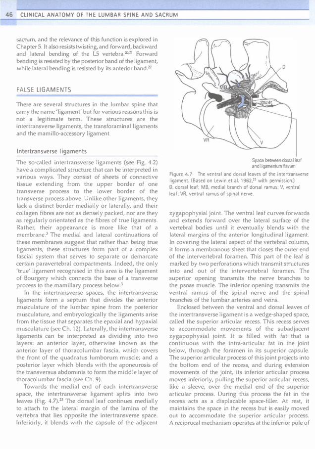
46 CLINICAL ANATOMY OF THE LUMBAR SPINE AND SACRUM
saoum, and the relevance of this function is explored in Chapter 5. It also resists twisting, and forward, backward and lateral bending of the 15 vertebra.20.21 Forward bending is resisted by the posterior band of the ligament, while lateral bending is resisted by its anterior band'2
FALSE LIGAMENTS
There are several structures in the lumbar spine that carry the name 'ligament' but for various reasons this is not a legitimate term. These structures are the intertransverse Ligaments, the transforaminal Ligaments and the mamillo-accessory ligament.
Intertransverse ligaments
The so-called intertransverse ligaments (see Fig. 4.2) have a complicated structure that can be interpreted in various ways. They consist of sheets of connective tissue extending from the upper border of one transverse process to the lower border of the transverse process above. Unlike other ligaments, they lack a distinct border medially or laterally, and their collagen fibres are not as densely packed, nor are they as regularly orientated as the fibres of true ligaments. Rather, their appearance is more like that of a membrane.] The medial and lateral continuations of these membranes suggest that rather than being true ligaments, these structures form part of a complex fascial system that serves to separate or demarcate certain paravertebral compartments. Indeed, the only 'true' ligament recognised in this area is the ligament of Bourgery which connects the base of a transverse process to the mamillary process below.3
In the intertransverse spaces, the intertransverse ligaments form a septum that divides the anterior musculature of the lumbar spine from the posterior musculature, and embryologically the ligaments arise from the tissue that separates the epaxial and hypaxial musculature (see Ch. 12). Laterally, the intertransverse ligaments can be interpreted as dividing into two layers: an anterior layer, otherwise known as the anterior layer of thoracolumbar fascia, which covers the front of the quadratus lumborum muscle; and a posterior layer whkh blends with the aponeurosis of the transversus abdominis to form the middle layer of thoracolumbar fascia (see Ch. 9).
Towards the medial end of each i.ntertransverse space, the intertransverse ligament splits into two leaves (Fig. 4.7).23 The dorsal leaf continues medially to attach to the lateral margin of the lamina of the vertebra that lies opposite the intertransverse space. Inferiorly, it blends with the capsule of the adjacent
Space be_n dorsal �al and ligamentum flavum
Figure 4.7 The ventral and dorsal leaves of the intertransverse ligament. (Based on lewin et al. 1962,23 with permission.) D, dorsal leaf; MS. medial branch of dorsal ramus; V. ventral leaf; VR. ventral ramus of spinal nerve.
zygapophysial joint. The ventral leaf curves forwards and extends forward over the lateral surface of the vertebral bodies until it eventually blends with the lateral margins of the anterior longitudinal ligament. In covering the lateral aspect of the vertebral column, it forms a membranous sheet that doses the outer end of the intervertebral foramen. This part of the leaf is marked by two perforations which transmit stnlctures into and out of the intervertebral foramen. The superior opening transmits the nerve branches to the psoas muscle. The inferior opening transmits the ventral ramus of the spinal nerve and the spinal branches of the lumbar arteries and veins.
Enclosed between the ventral and dorsal leaves of the intertransverse ligament is a wedge-shaped space, called the superior articular recess. This recess serves to accommodate movements of the subadjacent zygapophysial joint. It is filled with fat that is continuous with the intra-articular fat in the joint below, through the foramen in its superior capsule. The superior articuJar process of this joint projects into the bottom end of the recess, and during extension movements of the joint, its inferior articular process moves inferiorly, pulling the superior articular recess, like a sleeve, over the medial end of the superior articular process. During this process the fat in the recess acts as a displacable space-filler. At rest, it maintains the space in the recess but is easily moved out to accommodate the superior articular process. A reciprocal mechanism operates at the inferior pole of

the joint, where a pad of fat over the vertebral lamina maintains a space between the lamina and the multifidus muscle into which the inferior articular process can move.
Transforaminal ligaments
The transforaminal ligaments are narrow bands of collagen fibres that traverse the Quter end of the intervertebral foramen. Five types of such bands have been described, according to their specific attachments (Fig. 4.8):"
• The superior corporotransverse ligaments connect the lower posterolateral comer of a vertebral body with the accessory process of the transverse process of the same vertebra.
A
c
c
The ligaments of the lumbar spine 47
• The inferior corporotransverse Ligaments connect the lower posterolateral comer of a vertebral body with the transverse process below.
• The superior transforaminal ligaments bridge the inferior vertebral notches, and the inferior transforaminal ligaments bridge superior vertebral notches.
• The midtransforaminal ligaments run from the posterolateral comer of an anulus fibrosus to the zygapophysial joint capsule and ligamentum flavum behind.
Transforaminal ligaments are not always present. The overall incidence of all types is around 47<'10, with the superior corporotransverse being the most common type (27%).24 For two reasons, they are not strictly ligaments. First, their structure resembles
B
o Figur� 4.8 Th� tr3nsforamin31Iig3m�nts. (Bas�d on Golub and SilY�rman 1969.14) (A) Supfrior and inffrior corporotranSYfrsf ligamfnts. (B) Supfrior transforaminalligamfnt. (el Middlf transforaminalligamfnt. (0) Inffrior transforaminal ligamcnt.

48 CLINICAL ANATOMY OF THE LUMBAR SPINE AND SACRUM
bands of fascia more than ligaments proper. Secondly, except {or the inferior corporotransverse ligament, they do not connect two separate bones, and the mjdtransforaminal variety is not connected. to any bones. Accordingly, they are more correctly interpreted as
bands of fascia, and in view of their location it is most likely that they represent thickenings in the ventral leaf of the intertransverse ligament.
Mamillo-accessory ligament
A tight bundle of collagen fibres of variable thickness bridges the tips of the ipsilateral mamillary and accessory processes of each lumbar vertebra (Fig. 4.9). This structure has been called the mamilJo-accessory Iigament2S but it is not a true ligament because it connects two pOints on the same bone. Moreover, its cord-like structure resembles a tendon more than a
AP MP MAL
ligament, and indeed it has been interpreted as representing a tendon of the semispinalis musculature in the lumbar region.25 The ligament may be ossified, converting the mamilla-accessory notch into a bony foramen, The prevalence of this change was found in one study to be 10% at the L5 1evel,2S while in another study it was 28% at LS, 10% at L4 and 3% at L3.26
The Ligament has no biomechanical significance, but its significance lies in the fact that it covers the medial branch of the dorsal ramus of the spinal nerve as it runs through the mamilla-accessory notch. Furthermore, when the ligament is ossified, the foramen it forms can be an apparent anomaly evident on cr scans.Z7 Ossification of the ligament, however, is a normal phenomenon without any pathological significance. It has been suggested that the ligament may be a site of entrapment of the nerve beneath it28 but this has not been verified clinically.
Figure 4.9 The mamillo-accessory ligaments (MAL). AP, accessory process; MP, mamillary process. Note the foramina under the ligaments, through which pass the medial branches of the lumbar dorsal rami.
References
1. Williams PL, ed. Gray's Anatomy, 38th eeln. Edinburgh: Churchill Livingstone; 1995.
2. Francois RJ. Ligament insertions into the human lumbar vertebral body. Acta Anal 1975; 91:467-480.
3. Vallois HV. Arthologie. In: Nicolas A, ed. Poirier and Charpy's Trait� d'Anatomie Humaine, Vol. 1. Paris: Masson; 1926.
4. Coventry MS, Ghormley RK. Kemohan JW. The intervertebral disc: its microscopic anatomy and pathology. Part I. Anatomy, development and phYSiology. J Bone Joint Surg 1945; 27:105-112.
5. Naffziger HC, Inman V, Saunders J8 de CM. Lesions of the intervertebral disc and ligamenta £lava. Surg Gynec Obste. 1938; 66:288-299.
6. Ramsey RH. The anatomy of the ligamenta £lava. Clin Orthop 1966; 44:129-140.
7. Yong-Hing K, Reilly j, Kirkaldy-Willis WHo The ligamenrum flavum. Spine 1976; 1:226-234.
8. Yahia LH, Garzon 5, Strykowski H et al. Ultrastrucrure of the human interspinous Iiga.ment and Iigamenrum flavum: a preliminary srudy. Spine 1990; 15:262-268.
9. Twomey LT, Taylor JR. Sagittal movements of the human lumbar vertebral column: a quantitative srudy of the role of the posterior vertebral elements. Arch Phys Moo Rehab 1983; 6-1:322-325.
10. Nachemson AL, Evans JH. Some mechanical properties of the third human lumbar interlaminar ligament (ligamenrum flavum). J Biomech 1968; 1:211-220.

11. Heylings DJA. Supraspinous and interspinous ligaments of the human spine. J Anal 1978; 125:127-131.
12. Yahia LH, Drouin G, Maurais G et a!. Etude de 13 structure microscopique des ligaments post�rieurs du rachis lombaire. lnt Drihop 1989; 13:207-216.
13. Hukins OWL. Kirby Me, Sikoryn TA et al. Comparison or structure, mechanical properties, and functions of lumbar spinal ligaments. Spine 1990; 15:787-795.
14. Rissanen PM. The surgical anatomy and pathology of the supraspinous and interspinous ligaments of the lumbar spine with special reference to ligament ruptures. Acta Orthop Scand 1960; Supp!. 46:1-100.
15. Shellshear JL, Macintosh NWC. The transverse process of the fifth lumbar vertebra. 10: Shellshear JL, Macintosh NWG, eds. Surveys of Anatomical Fields. Sydney: Grahame; 1949: Ch. 3, 21-32.
16. Hanson r. Sonesson B. The anatomy of the iliolumbar ligament. Arch Phys Med Rehab 1994; 75:1245-1246.
17. Pool-Goudzwaard AL. Kleinrensink CJ, Snijders CJ et a!. The sacroiJjac part of the iliolumbar ligament. J Anal 2001;199:457-463.
18. Luk KDK, Ho He. Leong JCY. The iliolumbar ligament. A shJdy of its anatomy. development and clinical significance. J Bone Joint SUTg 1986; 688:197-200.
19. Uhloff HK. Prenatal development of the iliolumbar ligament. J Bone Joint Surg 1993; 758:93-95.
The ligaments of the lumbar spine 49
20. Chow DHK, Luk KDK, Leong ICY et al. Torsional stability of the lumbosacral junction: significance of the iliolumbar ligament. Spine 1989; 14:611-615.
21. Yamamoto I, Panjabi MM. Oxland TR et al. The role of the iliolumbar ligament in the lumbosacral junction. Spine 1990; 15:1133--1141.
22. Leong JCY, Luk KDK, Chow DHK et al. The biomechanical functions of the iliolumbar ligament in maintaining stability of the lumbosacral junction. Spine 1987 12:669-;;74.
23. Lewin T, Moffet B, Viidik A. The morphology of the lumbar synovial intervertebral jOints. Acta Morphol Neerlando-Scand 1962; 4:299-319.
24. Golub BS, Silvennan B. Transforaminal ligaments of the lumbar spine. J Bone Joint Surg 1969; 51A:947-956.
25. Bogduk N. The lumbar mamiIJa-accessory ligament. Its anatomical and neurosurgical significance. Spine 1981; 6:162-167.
26. Ninghsia Medical College. Anatomical observations on lumbar nerve posterior rami. Chin Med J 1978; 4:492-4%.
27. Beers GJ, Carter AP. McNary WE Vertical foramina in the lumbosacral region: cr appearance. Am J Roentgenol 1984; 143:1027-1029.
28. Bradley KC. The anatomy of backache. Aust NZ J Surg 1974; 44:227-232.

Chapter 5
The lumbar lordosis
and the vertebral canal
CHAPTER CONTENTS
The lumbar lordosis 51 Magnitude 53 Stability 53
The vertebral canal 54
THE LUMBAR LORDOSIS
The intact lumbar spine is formed when the five lumbar vertebrae are articulated to one another (Fig. 5.1). Anteriorly the vertebral bodies are separated by the intervertebral discs and are held together by the anterior and posterior longitudinal ligaments. Posteriorly the articular processes form the zygapophysiaJ joints, and consecutive vertebrae are held together by the supraspinous, interspinous and intertransverse ligaments and the ligamenta flava.
Although the lumbar vertebrae can be articulated to form a straight column of vertebrae, this is not the shape assumed by the intact lumbar spine in the upright posture. The reason for this is that the sacrum, on which the lumbar spine rests, is tilted forwards, so that its upper surface is inclined downwards and forwards. From radiographs taken in the supine position, the size of this angle with respect to the horizontal plane of the body has a mean value of about 42·-45·,'-3 and is said to increase by about S· upon standing.l
If a straight lumbar spine articulated with the sacrum, it would consequently be inclined forwards. To restore an upward orientation and to compensate for the inclination of the sacrum, the intact lumbar spine must assume a curve (see Fig. 5.1). This curve is known as the lumbar lordosis.
The junction between the lumbar spine and the sacrum is acrueved through joints like those between the lumbar vertebrae. Anteriorly, the body of the L5 vertebra forms an interbody jOint with the first sacral vertebra, and the intervertebral disc of this joint is known as the lumbosacral disc. Posteriorly, the inferior articuJar processes of L5 and the superior articular processes of the sacrum form synovial joints, known either as the LS-S1 zygapophysial joints or as
51

52 ClINICAL ANATOMY OF THE LUMBAR SPINE AND SACRUM
SSL -----1 ALL
ZJ -------'\r-
ISL ---r'=
IVD
Figure 5.1 Lateral view of the intact, upright lumbar spine. showing its curved shape. ALL anterior longitudinal ligament; IVO, intervertebral disc; 1St.. interspinous ligament; SSt.. supraspinous ligament; ZJ, zygapophysial joint.
the lumbosacral zygapophysiaJ joints. A ligamentum navum is present between the laminae of L5 and the sacrum, and an interspinous ligament connects the L5 and Sl spinous processes. However, there is no supraspinous ligament at the L5-S1 level,· nor are there intertransverse ligaments, the latter having been replaced by the iliolumbar ligament.
The shape of the lumbar lordosis is achieved as a result of several factors. The first of these is the shape of the lumbosacral intervertebral disc. This disc is unlike any of the other lumbar intervertebral discs in
that it is wedge shaped. Its posterior height is about 6-7 mm less than its anterior height.s Consequently, when the L5 vertebra is articulated to the sacrum, its lower surface does not lie parallel to the upper surface of the sacrum. It is still inclined forwards and downwards but less steeply than the top of the sacrum. The angle formed between the bottom of the 15 vertebra and the top of the sacrum varies from individual to individual over the range 6--29- and has an average size of about 16' (Fig. 5.2)'
The second factor that generates the lumbar lordosis is the shape of the L5 vertebra. Like the
--- ------------"'"'-."... Figurt! 502 Somt! of tht! anglt!s USf!d to dt!5Crjb� tht! lumbar spint!o 1, anglt! formed by the top of the sacrum and the horizontal plan� (mean value about SOO); 2, angle between th� bottom of L5 and the top of the sacrum (mean value 16"); 3, angle b�tween th� top of 11 and the sacrum, USf!d to measure the lumbar lordosis (mean value: about 70").
lumbosacral disc, the L5 vertebral body is also wedge shaped. The height of its posterior surface is some 3 mm less than the height of its anterior surface.6 As a consequence of the wedge shape of both the L5 body and the lumbos.:1cral disc, the upper surface of L5 lies much closer to a horizontal plane than does the upper surface of the sacrum.
The remainder of the lumbar lordosis is completed simply by indination of the vertebrae above LS. Each vertebra is inclined slightly backwards in relation to the vertebra below. As a resuJt of this inclination, the anterior parts of the anuli fibrosi and the anterior longitudinal ligament are stretched. Posteriorly, the intervertebral discs are compressed slightly, and the inferior articular processes slide downwards in relation to the superior articular processes of the vertebra below, and may impact either the superior articular process or the pedicle below. The latter

phenomenon has particular bearing on the weightbearing capacity of the zygapophysial joints and is described further in Chapter 8.
The form of the curve thus achieved is such that. in the upright posture, the LJ vertebra is brought to lie vertically above the sacrum. The exact shape of the lumbar lordosis at rest varies from individual to individual, and it is difficult to define what might be called the 'normal' lumbar lordosis.
Magnitude
Various parameters have been used by different investigators to quantify the curvature of the lumbar lordosis, although they all involve measuring one or other of the angles formed by the lumbar vertebral bodies (see Fig. 5.2). Some have used the angle formed by the planes through the top surface of L 1 and the top surface of the sacrum/.8 and this could be called the 'LJ-S1 lordosis angle'. Fernand and Fox (1985)' measured the angles between the top of L2 and the top of the sacrum, and between the top of L2 and the bottom of LS, which they called, respectively, the 'lumbosacral lordotic anglc' and the 'Iumbolumbar lordotic angle'. Others have measured the angle between the top of L3 and the sacrum,1O or the angle formed between planes that bisect the LJ-L2 disc and the L5--S1 disc.II.12 Consequently, the measures obtained in these various studies differ somewhat from one another. Nevertheless they all show substantial ranges of variation.
In radiographs taken in the supine position, the angle between the top of L1 and the top of the sacrum varies from 20' to more than 60' but has an average value of about SO-.1 In the standing position, this same angle has been measured as 67 (±3 standard deviation, SD) in children, and 74 (±7 SD) in young males." The angle between the top of L2 and the sacrum has a range of 16c_8(Y and a mean valueof 45-.Q A value greater than 68' is considered to indicate a hyperlordotic curve.II However, despite a common belief that excessive lordosis is a risk factor for low back pain, comparison studies reveal that there is no correlation between the shape of the lumbar lordosis and the presence or absence of back pain symptoms.7.10.12
Stability
The foremost structural liability of the lumbar spine stems from the inclination of the sacrum. Because of the downward slope of the superior surface of the sacrum there is a constant tendency for the L5 vertebra, and hence the entire lumbar spine, to slide forwards down this slope under the influence of the
The lumbar lordosis and the vertebral canal 53
weight of the trunk; more so whenever additional weights are borne by the lumbar spine. In turn there is a similar though lesser tendency for the L4 vertebra to slide down the upper surface of the L5 vertebra. However, the lumbar spine is adapted to offset these tendencies, and these adaptations are seen in the structure of the articular processes and ligaments of L5 and other lumbar vertebrae.
As described in Chapter 3, the lumbar zygapophysial joints provide a bony locking mechanism that resists forward displacement, and the degree to which a joint affords such resistance is determined by its orientation. The more a superior articular process faces backwards, the greater the resistance it offers to forward displacement.
To resist the tendency for the L5 vertebra to slip forwards, the superior articular processes of the sacrum face considerably backwards. The average orientation of the LS-Sl zygapophysial joints with respect to the sagittal plane is about 45 with most lumbosacral zygapophysial joints assuming this orientation (see Fig. 3.4, p. 32). Only a minority of joints assume a greater or lesser angle. Joints with a greater angle, i.e. facing backwards to an even greater extent, provide greater resistance to forward displacement of LS, but they provide less resistance to axial rotation (twisting movements) of LS. Joints with an angle less than 45 provide greater protection against rotation but less against forward displacement. An angle of 45' is therefore a satisfactory compromise, allowing the lumbosacral zygapophysial joints to resist both rotation and forward displacement.
The L4-5 zygapophysiaJ joints are also orientated at about 45 (see Fig. 3.4) and thereby resist forward displacement of the L4 vertebra. Above lA, the slopes of the upper surfaces of the vertebral bodies are horizontal or inclined backwards, and there is no tendency, at rest, for the upper lumbar vertebrae to slide forwards. Consequently, there is less need for the upper IlLmbar zygapophysial joints to face backwards, and their angle of orientation is progressively less than 45 (see Fig. 3.4). Such resistance as may be required to resist forward displacement of these jOints during flexion of the lumbar spine is nevertheless afforded by the curved shape of their articular surfaces. Although their general orientation is closer to the sagittal plane, the anteromedial ends of the articular surfaces of the upper lumbar joints face backwards and can resist forward displacement, if required (see Ch. 3).
The second mechanism that stabilises the lum· bar lordosis is provided by the ligaments of the lumbar spine. At all levels, any tendency for a vertebra to slide forwards will be resisted by the anulus fibrosus of the underlying intervertebral disc. However, the anuli

54 CLINICAL ANATOMY OF THE LUMBAR SPINE AND SACRUM
Eibrosi are spared undue strain in this regard by the bony locking mechanism of the zygapophysial joints. Bony impaction will occur before the intervertebra1 discs are strained. However, shou1d the mechanism of the zygapophysial joints be compromised by unsuitable orientation, or by disease or injury, then the resistance of the anuli fibrosi will be invoked to a greater extent.
By connecting the L5 transverse processes to the ilium, the iliolumbar ligaments, through their sheer size, provide a strong additional mechanism that prevents the L5 vertebra from sliding forwards. The tension sustained through the iliolumbar ligament is evident in the size of the L5 transverse processes. These are unlike the transverse processes of any other lumbar vertebra. instead of thin flat bars, they are thick and pyramidal. Moreover, instead of stemming just from the posterior end of the pedicle, they have an enlarged base that extends forwards along the pedicle as far as the vertebral body. This modification of structure can be interpreted as being due to the modelling of the bone in response to the massive forces transmitted through the L.S transverse processes and the iliolumbar ligaments.
The anterior longitudinal ligament, and in a similar way the anterior fibres of the anuli fibrosi, plays a further role in stabilising the lumbar lordosis. If the lumbar spine bows forwards, the anterior ends of the vertebral bodies will attempt to separate but this will be resisted by the anterior longitudinal ligament and the anterior fibres of the anuH fibrosi. EventuaUy an equilibrium will be established in which any force tending to separate the vertebral bodies will be balanced exactly by the tension in the anterior
ligaments. Any increase in force will be met by increased tension in the ligaments. In this way, the anterior ligaments endow the curved lumbar spine with a resilience. This mechanism is analogous to the 'springiness' that can be felt in a long wooden rod or a plastic ruler that is stood on end and deformed into an arc.
One of the advantages of a curved lumbar spine lies in this resilience. By being curved, the lumbar spine is protected to an appreciable extent from compressive forces and shocks. In a straight lumbar spine, an axial compressive force would be transmitted through the vertebral bodies and intervertebral discs, and the only mechanism to protect the lumbar vertebrae would be the shock-absorbing capacity of the intervertebral discs (see Ch. 2). In contrast, in a curved lumbar spine, compressive forces are transmitted through the posterior ends of the intervertebral discs while the anterior ends of the vertebral bodies tend to separate. In other words, compression tends to accentuate the lumbar lordosis. This tendency will cause the anterior ligaments to become tense, which, in tum, will resist the accentuation. In this way, some of the energy of the compressive force is diverted into stretching the anterior ligaments instead of being transmitted directly into the next vertebral body.
THE VERTEBRAL CANAL
In the intact lumbar spine, the vertebral foramina of the five lumbar vertebrae are aligned to form a continuous channel called the vertebr.1 c.nal (Fig. 5.3). The anterior wall of this canal is fonned by the posterior
Figure 5.3 Lateral view of a prone lumbar spine with an arrow depicting the vertebral canal.

surfaces of the lumbar vertebrae, the intervening discs and the posterior longitudinal ligament. The posterior wall is formed by the laminae of the vertebrae and the intervening ligamenta flava. Because operations on the lumbar spine are most frequently performed with the patient in the prone position, the anterior and posterior waUs of the vertebral canal are, by convention, alternatively referred to as the floor and roof of the vertebral canal. respectively.
The floor of the vertebral canal is not absolutely flat because the posterior surfaces of the lumbar vertebral bodies exhibit slight curves, transversely and longitudinally. The posterior surfaces of the L1 to L3 vertebrae regularly exhibit a sUghl transverse concavity. In contrast L5 is slightly convex while L4 exhibits an intermediate curvature.I" Along the sagittal plane, the lumbar vertebrae present a slightly concave posterior surface so that in profile the noor of the vertebral canal presents a scalloped appearanceYi This scalloping is be�eved to be produced by the pulsatile, hydrostatic pressure of the cerebrospinal Auid in the dural sac, which occupies the vertebral canaL'o;
The lateral walls of the vertebral canal are formed by the pedicles of the lumbar vertebrae. Between th e pedicles, the lateral wall is deficient where the superior and inferior vertebral notches appose one another to form the intervertebral foramina. Each intervertebral foramen is bounded anteriorly by an intervertebral disc, the adjacent lower third of the vertebral body above, and the uppermost portion of the vertebral body below (Fig. 5.4). Above and below, each intervertebral foramen is bounded by a pedicle, while posteriorly it is bounded by a vertebral lamina and a zygapophysial joint. More accurately, the posterior boundary of each intervertebral foramen is the lateral portion of the ligamentum navum that covers the anterior aspect of the lamina and zygapophysial joint (see Ch. 4).
Subdivisions of the vertebral canal, recognised by surgeons because of their relationship to the spinal nerve roots,lf>-I<,I are the so-called radicular canals. These arc not true canals because they do not have boundaries around all their aspects. More accurately, they are only subdivisions of the space of the vertebral canal and intervertebral foramina, through which the spinal nerve roots run (see Ch. 10), but in so far as they form a series of bony relations to the course of the nerve roots, they may be regarded as canals.
Each radicular canal is a curved channel running around the medial aspect of each pedicle in the lumbar spine, and each can be divided into three segments. I"
The uppermost, or retrodiscal segment, lies above the level of the pedicle. Its anterior wall is formed by the intervertebral disc in this region, while its posterior wall is formed by the uppermost end of a superior
The lumbar lordosis and the vertebral canal 55
Figur� 5.4 laural vit:w of tht: boundarit:s of an intervt:rtt:bral foramt:n. 1, pedicl�; 2, back of v�rtt:bral body; 3, intt:rvt:rtt:bral disc; 4, back of vertebral body; 5, pedicle; 6, ligamt:ntum flavum; 7, zygapophysial jOint.
articular process (Fig. 5.5). This segment lacks a lateral wall because it lies opposite the level of an intervertebral foramen. Simijarly, it has no medial wall for in this direction it is simply continuous with the rest of the vertebral canal.
The parapedicular segment lies immediately medial to the pedicle, whkh therefore forms its lateral wall. Anteriorly, this segment is related to the back of the vertebral body, while posteriorly it is covered by the vertebral lamina and the anteromedial edge of the superior articular process that projects from this lamina (see Fig. 5.5). Technically, this segment of the radicular canal is simply the lateral portion of the vertebral canal opposite the level of a pedicle, and for this reason this segment is also known as the lateral recess (of the vertebral canal). A lateral recess is therefore present on both sides of the vertebral canal opposite each of the lumbar pedicles.
The third segment of the radicular canal is formed by the upper part of the intervertebral foramen: that part behind the vertebral body and below the upper pedicle (see Fig. 5.5).
The anatomical relevance of the radicular canals is that the lumbar nerve roots run along them; the anatomy of these nerves is described in Chapter 10. The clinical relevance lies in the propensity for the nerve roots to be compressed by structural alterations in one or other of the structures that form boundaries to the canals.

56 CLINICAL ANATOMY OF THE LUMBAR SPINE AND SACRUM
A B
L
lAP
c
\--- P ---F-=-::::;
VB
Figure 5.5 The radicular canals. (A) The location of the radicular canals (shaded) in a dorsal view of the: lumbar spine. (B) A view of the radicular canals from within the vertebral canal, showing their lateral. anterior and posterior boundaries. (el The anterior and lateral boundaries of the radicular canals. viewed from behind. (D) The posterior and lateral boundaries of the radicular canals, 35
seen from within the vertebral canal, looking at its roof. The ligamentum flavum has not been induded (see also Fig. 4.5B). lAP, inferior articular process; IVD, intervertebral disc; L. lamina; LF, ligamentum flavum; P, pedicle; SAP. superior articular process; VB, vertebral body.
Another concept of relevance to nerve root compression concerns narrowing of the vertebraJ canal. The shape and size of the lumbar vertebral canal govern the amount of space available for the nerves that the canal transmits, and if this space is in any way lessened by encroachment of the boundaries of the
canal, the condition is referred to as canal stenosis or spinal stenosis.20-26
In transverse section, the lumbar vertebral canal varies in shape. it is oval at upper lumbar levels, becoming triangular more caudally, sometimes assuming a trefoil shape at lower lumbar levels (Fig. 5.6)"

Figure 5.6 The shape of the vertebral canal in transverse section, (A) Oval outline of upper lumbar vertebrae. (B) Triangular shape of lower lumbar vertebrae. (e) Trefoil shape found at lower lumbar levels. (0) Congenital spinal stenosis. (E) Acquired spinal stenosis of a triangular vertebral canal due to arthrosis of the zygapophysial joints. (F) Acquired spinal stenosis of a trefoil vertebral canal due to arthrosis of the zygapophysiaJ joints.
References
1. Arnoldi Cc, Brodsky AE, Cauchoix 1 ct aL Lumbar spinal stenosis. Clin Orthop 1976; 115:4-5.
2. Bose K, Balasubramaniam P. Nerve root canals of the lumbar spine. Spine 1984; 9:1�18.
3. Crock HV. Normal and pathological anatomy of the lumbar spinal nerve root canals. J Bone Joint Surg 1981; 636:487-490.
4. Dommisse GF. Morphological aspects of the lumbar spine and lumbosacral regions. Orthop Clio North Am 1975; 6:163-175.
5. Ehni G. Significance of the small lumbar spinal canal:cauda equina compression syndromes due to spondylosis. J Neurosurg 1962; 31:490-494.
The lumbar lordosis and the vertebral canal 57
The term 'trefoil' refers to a tri angular shape in which the angles are stretched or accentuated.28 The basal angles of the triangular or trefoil outline are fonned by the lateral recesses of the vertebral canal.
The shape and size of the vertebral canal can be abnormally small as a result of aberrations in the development of the neural arch. In relation to the size of the vertebral canal, the pedicles may be too thick or the articular process may be too large. Ln effect, the space left in the vertebral canal becomes relatively too small for the volume of nerves that it has to transmit. This condition is called congenital or developmental spinal stenosis,2o but by itself developmental stenosis does not cause compression of nerves. Jt only renders the patient more likely to compression in the face of the slightest aberration of the boundaries of the vertebral canal.20,23
Acguired spinal stenosis occurs whenever any of the structures surrounding the vertebral canal is affected by disease or degeneration that results in enlargement of the structure into the space of the vertebra'! canal. Examples of such processes include buckling of the ligamentum Aavuffi, osteophytes from the zygapophysial joints or intervertebral discs, and intervertebral disc herniations or bulgesp,20,23,25 Such changes may occur at single levels in the vertebral canal or at multiple levels, and symptoms may arise either from the disease process that cansed the changes or as a result of compression of one or more nerves by the encroaching structure. The pathogenesis of symptoms in spina.l stenosis is described further in Chapter 15.
6. Eisenstein S. The trefoil configuration of the lumbar vertebral canaL 1 Bone Joint Surg 1980; 62B:73-77.
7. Epstein lA, Epstein BS, Levine L Nerve root compression associated with narrowing of the lumbar spinal canal. J Neural Neurosu.rg Psychiatry 1962; 25:165-176.
8. Farfan HF. Huberdeau RM, Dubow HI. Lumbar intervertebral disc degeneration. The influence of geometrical features on the pattem of disc degenerationa post-mortem study. J Bone Joint Surg 19n; 54A:492-510.
9. Femand R, Fox DE. Evaluation of lumbar lordosis. A prospective and retrospective study. Spine 1985; 10:799-803.

58 CLINICAL ANATOMY OF THE LUMBAR SPINE AND SACRUM
10. Gilad I, Nissan M. Sagittal evaluation of elemental geometrical dimensions of human vertebrae. J Anal 1985; 143:11:;"120.
1 J. I Jansson T, Bigos 5, Beecher Pet al. The lumbar lordosis in acute and chronic low-back pilin. Spine 1985;
10: I 'i4-155.
12. t-Iellems HK, Keates TE. Measurement of the normal lumbosacral angle. Am J Roentgenol 1971; 113:642--645.
13. Heylings DJA. Supraspinous and interspinous ligaments of the human spine. J Anal 1978; 125:127-131.
14. Kirkaldy-Willis WH, Wedge } 1-1, Yong-Hing K et al. Pathology and pathogenesis of lumbar spondylosis and stenosis. Spine 1978; 3:319-328.
IS. Larsen JL. The posterior surface of the lumbar \'ertcbral bodies. Part 1. Spine 1985 10:50-58.
16. Larsen Jt. The posterior surface of the lumbar \'ertebral bodies. Part 2. An anatomic investigation concerning the curvatures in the horizontal plane. Spine 1985;
10:901-906.
17. Parkin IG, Harrison GR. The topographical anatomy of the lumbar epidural space. J Anal 1985; 141:211-217.
18. Pearcy M, Porlck t Shepherd}. Three-diml?nsional X-ray analysis of normal movement in the lumbar spine. Spine 198-1; 9:294-297.
19. Pclkcr RR, Gage JR. The correlation of idiopathic lumbar scoliosis and lumbar lordosis. Clin Orthop 1982;
163:199-201.
20. Pope MH. Bevins T, Wilder OC et al. The relationship beh'Veen anthropometric, poshlral, muscular, and mobility characteristics of males ages IS-55. Spine 19&5; 10:6++-648.
21. Schmorl G, Junghanns II. The Human Spine in Health and Disease, 2nd American cdn. New York: Grune & Stratton; 1971: 18.
22. Splithoff CA. Lumbosacral junction: roentgenographic comparisons of patients with and without backache. JAMA 1953; 152:199-201.
23. Torgerson WR, Dotter WE. Comparative roentgenographic study of the asymptomatic and symptomatic lumbar spine.J Bone Joint Surg 1976;
58A:850-853.
24. Verbiest H. A mdicular syndrome from developmental narrowing of the lumbar vertebral canal. J Bone Joint Surg 1954; 368:230-237.
25. Vcrbiest H. Pathomorphological aspects of developmental lumbar !lotcnosis. Orthop Clin North Am 1975; 6:177-1%.
26. Verbiest H. Fallacies of the present definition, nomenclature and classification of the stenoses of the lumbar vertebral canal. Spine 1976; 1:217-225.
27. Vital }M, Lavigno/le B, Grenier N el al. Anatomy of the lumbar radicular canal. An.lt Clin 1983; 5:'41-151.
28. Von Lackum ilL. The lumbos.lcral region. An anatomic study and some clinicJI observations. JAMA 1924;
82:1109-1114.


The concept of moments applies to all situations where joints bend, whether they are acted upon by muscles or gravity. The moment generated by a muscle is the product of the force exerted by the muscle and the perpendicular distance between the axis of rotation of the joint and the line of action of the muscle (Fig. 7.15). In the case of the vertebral column, movements such as flexion are frequently exerted by gravity. The force involved is the weight of the trunk leaning forwards of the lumbar spine and it is exerted vertically downwards on the centre of mass
of the trunk (Fig. 7.16). The magnitude of the force acting on a given joint in the lumbar spine is calculated as the mass of the trunk above that joint multiplied by g. The moment arm is the perpendicular distance from the joint in question to the line of action of the force (see Fig. 7.16). Clearly, the further a subject leans forward, the longer this moment arm and the greater the resultant moment. Conversely, the more upright a subject stands, the shorter the moment arm and the smaller the flexion moment (Fig. 7.17).


Chapter 8
Movements of the lumbar •
spine
CHAPTER CONTENTS
Axial compression 77
Fatigue failu.. 80 Axial distraction 81 Flexion 81
Failure 84 Extension 85 Axial rotation 85
Fatigue failure 87
Lateral flexion 87
Rotation in flexion 87
Range of movement 88
-,
Clinical implications 90 Axes of sagittal rotation 91
The principal movements exhibited by the lumbar spine and its individual joints are axial compression, axial distraction, flexion, extension, axial rotation and lateral flexion. Horizontal translation does not naturally occur as an isolated, pure movement, but is involved in axial rotation.
AXIAL COMPR ESSION
Axial compression is the movement that occurs during weight-bearing in the upright posture, or as a result of contraction of the longitudinal back muscles (see Ch. 9). With respect to the interbody joints, the weight-bearing mechanisms of the intervertebral discs have already been described in Chapter 2, where it was explained how the nucleus pulposus and anulus fibrosus cooperate to transmit weight from one vertebra to the next. It is now appropriate to add further details.
During axial compression, both the anulus fibrosus and nucleus pulposus bear the load and transmit it to the vertebral endplates (see Ch. 2). In a normal disc, the outermost fibres of the anulus do not participate in bearing the load. Otherwise, the compression load is borne uniformly across the inner, anterior anulus and nucleus, but with a peak stress over the inner, posterior anuJus (Fig. 8.1 )1-3 In older discs tllis posterior peak is larger.2.3
Compression squeezes water out of the disc.,a-6 Under a 100 kPa load, the nucleus loses some 8% of its water and the anulus loses 11%.7-9 The loss of water results in a relative increase in the concentration of electrolytes remaining in the disc, and this increased concentration serves to re-imbibe water into the disc once compression is released.8
Under compression, the vertebral bodies around a disc approximate and the disc bulges radially.s,7,lo The
77

78 CLINICAL ANATOMY OF THE LUMBAR S PINE AND SACRUM
2MPa
Posterior Anterior
Figur� 8.1 Th� stress profile of an intervertebral disc from the posterior to the anterior anulus during axial compression. (Based on Adams et aL 1 993.S3)
vertebral bodies approximate because the vertebral endplatcs bow ilway from the disc.1D-12 Indeed, the deflection of each end plate is almost equal to half the displacement of the vertebrae. II This amounts to a strain of approximately 3% in the endplate.l1 The disc bulges because, as the anulus loses height peripherally, the redundant length must somehow be accommodated, i.c. the lamellae of the anulus must buckle. Nuclear pressure normally prevent:; buckling inwards, leaving outward radial bulging as the only means of accommodating loss of disc height. The bulging IS greater anteriorly than at the posterolateral comer of the disc, and induces a strain in the anulus fibroslls of about 21Yo per mm loss of disc height.1l Removing part of the nucleus (as occurs in discectomy) increases both the los� of disc height and the radial bulge. I"
The load on the end plate during compression is evenly distributed over its surface, there being no greater load o\"er the nucleus pulposus than over the anulus fibrosusY" The endplate bows, however, because it; periphery its strongly supported by the underlying cortical bone of the vertebra, whereas its central portion is supported by the slightly weaker trabecular bone of the vertebral body. This trabecular support is critical to the integrity of the end plate.
When excessive loads are applied to normal intervertebral discs, the trabeculae under the endplates fracture and the end plates themselves fracture, typically in their central region, i.e. over the nucleus PUIPOSllS, rather than m-cr the anulus.".lb-Iq With the application of very great loads the entire end plate may fractu re. 1I�-20
In this context, it is noteworthy that the end plates are the \."eakest components of the intervertebral disc in the face of axial compression. Provided the anulus is healthy and intact, increasing the lo..ld causes one or other of the end plates to fail, by fracturing, sooner than the anulus fibrosus fails, by rupturing."·UU<i This
phenomenon has particular ramifications in the pathology of compression injuries of the lumbar spine and disc degradation (see Ch. 15), and has its basis in the relative strengths of the anuJus fibrosus and the bone of the vertebral body. Calculations have shown that the anulus fibrosus can withstand a pressure of 3.2 x 10' Nm' but cancellous bone yields at 3.4 x 10" Nm .'. ' Consequently, end plates would be expected to rail sooner than the anulus fibrosus when the disc is subjected to axial compression.
With respect 10 the vertebral bodies, in adults under the age of 40, between 25 and 55% of the weight applied to a vertebral body is borne by the trabecular bone;IO.2I.22 the rest is borne by the cortical shell. In older individuals this proportion changes, ror reasons explained in Chapler 13. Overall, Ihe strength of a vertebral body is quite great but varies cOruiiderably between individuals. The ultimate compressive strength of a vertebral body ranges between 3 and 12 kNB�' This strength is directly relaled to bone density23,25.2b and can be predicted to within 1 kN on the basis or bone density and endplate area determined by cr scanning.21 It also seems to be in\"ersely related to physical acth·ity, in that active individuals ha\"c stronger vertebrae.2S
Another factor that increases the load-bearing capacity of the vertebral body is the blood within its marrow spaces and intra-osseous veins (see Ch. 11). Compression of the vertebral body and bulging of the end plates causes blood to be extruded from the vertebra.5 Because this process requires energy, it buffers the vertebral body, to some extent, from the compressive lOc:lds applied to it.l'oI
During compression, intervertebral discs undergo an initial period of rapid creep, deforming about 1 .5 mm in the first 2-10 min depending on the size of the applied lo..ld.�ll Subsequently, a much slower but definite creep continues at about 1 mm per hour.]) Depending on age, a plateau is attained by about 90 min, beyond which no further creep occurs.ll
Creep underlies the variation in height changes undergone by individuals during activities of daily living. Over a 16-hour day, the pressure sustained by intervertebral discs during walking and sitting causes loss of Auid from the discs, which results in a 10% loss in disc height'" and a 16% loss of disc volume.:l2 Given that intervertebral discs account for just under a quarter of the height of the vertebral column, the 10°10 fluid loss results in individuals being 1-2°'0 shorter at the end of a day.:n-:t"i This height is restored during sleep or reclined rest, when the vertebral column is not axially compressed and the discs are rehydrated by the osmotic pressure of the disc proteoglycans.'" More(")\·er, it has been demon�trah...� that n.�t in the

supine position with the lower limbs flexed and raised brings about a more rapid return to fuJI disc height than does rest in the extended supine position.3�
The pressure within intervertebral discs can be measured using special needles,�38 and disc pressure measurement. or discometry, provides an index of the stresses applied to a disc in various postures and movements. Several studies have addressed this issue although for technical reasons virtually all have studied only the L3-4 disc.
In the upright standing posture, the load on the disc is about 70 kPa.17 Holding a weight of 5 kg in this posture raises the disc pressure to about 700 kPa.37,)'ol The changes in disc pressure during other movements and manoeuvres are described i.n Chapter 9.
Although the interbody joints are designed as the principal weight-bearing components of the lumbar spine (see Ch. 2), there has oc..oen much interest in the role that the zygapophysial joints play in weightbearing. The earliest studies in this regard provided indirect estimates of the Io.,d borne by the zygapophysial joints based on measurements of intradiscal pressure, and it was reported that the zygapophysial joints carried approximately 20% of the vertical load applied to an intervertebral joint.Jb This conclusion, however, was later retracted.-IO
Subsequent studies have variously reported that the zygapophysial joints can bear 28%41 or 40%42 of a vertically applied load. To the contrary, others have reported that 'compression did not load the facet joints ... very much'/l and that 'provided the lumbar spine is slightly flattened ... all the intervertebral compressive force is resisted by the disc'.oW
Reasons for these differences in the conclusions relate to the experimental techniques used and to the differing appreciation of the anatomy of the zygapophysial joints and their behaviour in axial compression.
Although the articular surfaces of the lumbar zygapophysial joints are curved in the transverse plane (see Ch. 3), in the sagittal and coronal planes they run straight up and down (although see Ch. 11). Thus, zygapophysial joints, in a neutral position, cannot sU5.tain vertically applied loads. Their articular surfaces run parallel to one another and parallel to the direction of the applied load. If an intervertebral joint is axially compressed, the articular surfaces of the zygapophysial joints will simply slide past one another. For the zygapophysial joints to participate in weight·bearing in erect standing, some aberration in their orientation must occur, and either of two mechanisms may operate singly or in combination to recruit the zygapophysial joints into wcight·bearing.
if a vertebra is caused to rock backwards on its intervertebral disc without also being allowed to slide
Movements of the lumbar spine 79
backwards, the tips of its inferior articular processes will be driven into the superior articular facets of the vertebra below (Fig. 8.2). Axial compression of the intervertebral joint will then result in some of the load being transmitted through the region of impaction of the zygapophysial joints. By rocking a pair of lumbar vertebrae, one can readily determine by inspection that the site of impaction in the zygapophysiaJ joints falls on the inferior medial portion of the facets. Formal experiments have shown this to be the site where maximal pressure is detected in the zygapophysial jOints of vertebrae loaded in extension.4';
Another mechanism does not involve the zygapophysial joint surfaces but rather the tips of the inferior articular processes. With severe or sustained axial compression, intervertebral discs may be narrowed to the extent that the i.nferior articular processes of the upper vertebra are lowered until their tips impact the laminae of the vertebra below (Fig. 8.3).'" Alternatively, this same impact may occur if an intervertebral jOint is axially compressed while also tilted backwards, as is the case in a lordotic lumbar spine bearing weight.4s-1H Axial loads can then be transmitted through the inferior articular processes to the laminae.
It has been shown that under the conditions of erect sitting, the zygapophysial jOints are not impacted and bear none of the vertical load on the intervertebral jOint. However, in prolonged standing with a lordotic spine, the impacted joints at each segmental level bear
Figure 8.2 When a vertebra rocks backwards, its inferior articular processes impact the lower face of the superior articular processes of the vertebra below.

80 CLINICAL ANATOMY OF THE LUMBAR SPINE AND SAC RUM
d"...c.J
D " III
l"
Figure 8.3 If an intervertebral joint is compressed (1), the inferior articular processes of the upper vertebra impact the laminae below (2), allowing weight to be transmitted through the inferior articular processes (3).
an average of some 16% of the axial load.4-l,47 In this regard, the lower joints (1.3-4, L4-s. LS-Sl) bear a relatively greater proportion (l9%), while the upper joints (Ll-2, L2-3) bear less (11%)" Other studies have shown that the actual load borne by impaction of inferior articular processes varies from 3--18% of the applied load, and criticaUy depends on the HII of the intervertebral joint.48 It has also been estimated that pathological disc space narrowing can result in some 70% of the axial load being borne by the inferior articular processes and laminae.""
It is thus evident that weight-bearing occurs through the zygapophysial joints only if the inferior articular processes impact either the superior articular facets or the laminae of the vertebra below. Variations in the degree of such impactions account for the variations in the estimates of the axial load carried by the zygapophysial joints." and explain why the highest estimates of the load borne are reported in studies in which the intervertebral joints have been loaded in the extended position:Il··U.��'il
Although the preceding account of axial compression emphasises the role of the discs and zygapophysiaJ jOints in weight-bearing, other components of the lumbar spine also participate. The shape of the lordotic lumbar spine a110ws the anterior longitudinal ligament
and the anterior portions of the anuli fibrosi to be involved in weight-bearing. Because of the curvature of the lordosis, the posterior parts of the intervertebral discs and the zygapophysial joints are compressed, but the anterior ligaments are stretched. Axial loading of a lordotic spine tends to accentuate the lordosis and, therefore, to increase the strain in the anterior ligaments. By increasing their tension, the anterior ligaments can resist this accentuation and share in the load-bearing.
In this way, the lordosis of the lumbar spine provides an axial load-bearing mechanism additional to those available in the intervertebral discs and the zygapophysial joints. Moreover, as described in Chapter 5, the tensile mechanism of the anterior ligaments imparts a resilience to the lumbar spine. The energy delivered to the Ligaments is stored in them as tension and can be used to restore the curvature of the lumbar spine to its original form, once the axial load is removed.
Fatigue failure
Repetitive compression of a lumbar interbody joint results in fractures of the subchondral trabeculae and of one or other of the end plates. This damage occurs at loads substantially less than the ultimate compression strength of these structures, and well within the range of forces and repetitions encountered in activities of daily living, work and sporting activities.
Loads of between 37% and 80% of ultimate compression strength, applied at 0.5 Hz. can cause subchondral fractures after as few as 2000 or even 1000 cycles.52 Loads between 50% and 80% of ultimate stress can cause subchondral and other vertebral fractures after fewer than 100 cycles.25
The probability of failure is a function of the load applied and the number of repetitions. Loads below 30% ultimate stress are unlikely to result in failure, even after 5000 repetitions; increasing the load increases the probability of failure after fewer repetitions" At loads of 50-60"10 of ultimate stress, the probability of failure after 100 cycles is 39%; at loads of 60-70% ultimate strength. this probability rises to 63%.23 The lesions induced range from subchondral trabecular fractures to impressions of an endplate, frank fractures of an endplate and fractures of the cortical bone of the vertebral body.2l Repetitions of loo and up to 1000 are within the calculated range for a variety of occupational activities, as are loads of 60% ultimate stress of an average vertebral body."
Endplate fractures result in a loss of disc height1b and changes in the distribution of stress across the nucleus and anulus.1053 The stress over the nucleus

and anterior anulus decreases, while that over the posterior anulus rises.l0�'i] This increase in stress causes the lamellae of the anulus to collapse inwards towards the nudeus, thereby disrupting the internal architecture of the disc.lO Thus, even a small lesion can substantially compromise the normal biomechanics of a disc. The clinical significance of these phenomena is explored further in Chapter 15.
AXIAL DISTRACTION
Compared to axial compression and other movements of the lumbar spine, axial distraction has been studied far less. One study provided data on the stress-strain and stiffness characteristics of lumbar intervertebral discs as a whole, and revealed that the discs are not as stiff in distraction as in compression.'iO This is understandable, for the discs are designed principally for weight-bearing and would be expected to resist compression more than tension. in a biological sense, this correlates with the fact that humans spend far more time bearing compressive loads - in walking, standing and sitting - than sustaining tensile loads, as might occur in brachiating (tree-climbing) animals.
Other studies have focused on individual elements of the intervertebral joints to determine their tensile properties. When stretched along their length, isolated fibres of the anulus fibrosus exhibit a typical 'toe' region between O�'o and 3% strain, a failure stress between 4 and 10 MPa, and a strain at failure between 9% and 15%; their stiffness against stretch ranges from 59 to 140 MPa" If the anulus is tested while still attached to bone and distracted along the longitudinal axis of the vertebral column, as opposed to along the length of the fibres, the failure stress remains between 4 and 10 MPa but the stiffness drops to between 10 and 80 MPa.<;'i These tensile properties seem to vary with location but the results between studies are conflicting. Isolated fibres seem to be stiffer and stronger in the anterior region than in the posterolateral region of the disc, and stiffer in the outer regions of the anulus than in the inner regions.'i] On the other hand, in intact specimens, the outer anterior anulus is weaker and less stiff than the outer posterior anulus.r;r;
The capsules of the zygapophysial joints are remarkably strong when subjected to longitudinal tension. A single capsule can sustain 600 N before failing.""" Figuratively, this means that a pair of capsules at a single level can bear twice the body weight if subjected to axial distraction.
However, the significance of these results lies not so much in the ability of elements of the lumbar spine to resist axial distraction but in their capacity to resist
Movements of the lumbar spine 8 1
other movements that strain them. The anulus fibrosus will be strained by anterior sagittal rotation and axial rotation, and the zygapophysial joint capsules by anterior sagittal rotation. Those movements are considered below.
There has been one study" that has described the behaviour of the whole (cadaVeric) lumbar spine during sustained axial distraction, to mimic the clinical procedure of traction. Application of a 9 kg weight to stretch the lumbar spine results in an initial mean lengthening of 7.5 mm. Lengthening is greater (9 mm) in lumbar spines of young subjects, and less in the middleaged (5.5 mm) and the elderly (7.5 mm). Sustained traction over 30 min results in a creep of a further 1.5 mm. Removal of the load reveals an immediate 'set' of about 2.5 mm, which reduces to only 0.5 mm by 30 min after removal of the load. Younger spines demonstrate a more rapid creep and do not show a residual 'set'. The amount of distraction is greater in spines with healthy discs (11-12 mm) and substantiaUy less (3-5 mm) in spines with degenerated discs.
Some 40% of the lengthening of the lumbar spine during traction occurs as a result of flattening of the lumbar lordosiS, with 6()O/u due to actual separation of the vertebral bodies. The major implication of this observation is that the extent of distraction achieved by traction (using a 9 kg load) is not great. It amounts to 60% of 7.5 mm of actual vertebral separation, which is equivalent to about 0.9 mm per intervertebral joint. This revelation seriously compromises those theories that maintain that lumbar traction exerts a beneficial effect by 'sucking back' disc herniations, and it is suggested that other mechanjsms of the putative therapeutic effect of traction be considered.57
The other implication of this study relates to the fact that the residual 'set' after sustained traction is quite small (0.5 mm), amounting to about 0.1 mm per intervertebral joint. Moreover, this is the residual set in spines not subsequently reloaded by body weight. One would expect that, in living patients, a 0.1 mm set would naturally be obliterated the moment the patient rose and started to bear axial compression. Thus, any effect achieved by therapeutic traction must be phasic, i.e. occurring during the application of traction, and not due to some maintained lengthening of the lumbar spine.
FLEX I O N
During flexion, the entire lumbar spine leans forwards (Fig. 8.4). This is achieved basically by the 'unfolding' or straightening of the lumbar lordosis. At the full range of forward flexion, the lumbar spine assumes a

82 CLINICAL ANATOMY OF THE LUMBAR S PINE AND SACRUM
FleKion
c-:)
... . ... ... ) , .... ··············#·1
\ /, .. ("\
.\ .. ':::<:::;)\ t .... r··
t._ ...
Figure 8.4 During flexion, the lumbar lordosis unfolds. and the lumbar spine straightens and leans forwards on the sacrum. The curvature of the lordosis may be reversed at upper lumbar levels but not at LS-Sl.
straight alignment or is curved slightly forwards, tending to reverse the curvature of the original lordosis (see Fig. 8.3). The reversal occurs principally at upper lumbar levels. Reversal may occur at the L4-S level but does not occur at the L5--S1 leveJ.58.5'Il Forward flexion is therefore achieved for the most part by each of the lumbar vertebrae rotating from their backward tilted position in the upright lordosis to a neutral position, in whkh the upper and lower surfaces of adjacent vertebral bodies are paralJel to one another. This relieves the posterior compression of the intervertebral discs and zygapophysial joints, prescnt in the upright lordotic lumbar spine. Some additional range of movement is achieved by the upper lumbar vertebrae rotating further forwards and compressing their intervertebral discs anteriorly.
It may appear that during flexion of the lumbar spine, the movement undergone by each vertebral body is simply anterior sagittal rotation. However, there is a concomitant component of forward translation as well.'W·act If a vertebra rocks forwards over its intervertebral disc, its inferior articular processes are raised upwards and stightly backwards (Fig. 8.5A). This opens a small gap between each inferior articular facet and the superior articular facet in the zygapophysial joint. As the lumbar spine leans forwards, gravity or muscular action causes the vertebrae to slide forwards, and this motion closes the gap between the facets in the zygapophysial joints (Fig. 8.56). Further forward translation will be arrested once impaction of the zygapophysial joints is re-established, but nonetheless a small forward translation will have occurred. At each intervertebral joint, therefore, flexion involves a combination of anterior sagittal rotation and a small amplitude anterior translation.
The zygapophysial joints play a major role in maintaining the stability of the spine in flexion, and much attention has been directed in recent years to the mechanisms involved. To appreciate these mechanisms, it is important to recognise that flexion involves both anterior sagittal rotation and anterior sagittal translation, for these two components are resisted and stabilised in different ways by the zygapophysial jOints.
Anterior sagittal translation is resisted by the direct impaction of the inferior articular facets of a vertebra against the superior articular facets of the vertebra below, and this process has been fully described in Chapter 3. This mechanism becomes increasingly important the further the lumbar spine leans forward, for with a greater forward inclination of the lumbar spine, the upper surfaces of the lumbar vertebral bodies are inclined downwards (Fig. 8.6), and there will be a tendency for the vertebrae above to slide down this slope.
The cardinal ramification of the anatomy of the zygapophysial joints with respect to forward shear is that in joints with flat articular surfaces, the load will be borne evenly across the entire articular surface (see Ch. 3), but in joints with curved articular surfaces the load is con· centrated on the anteromedial portions of the superior and inferior articular facets (see Ch. 3). Formal experiments have shown that during Aexion, the highest pressures are recorded at the medial end of the lumbar zygapophysial joints," and this has further bearing on the age changes seen in these joints (see Ch. 13).
The anterior sagittal rotation component of Aexion is resisted by the zygapophysial joints in a different way. The mechanism involves tension in the joint capsuJe. Flexion involves an upward sliding movement of each inferior articular process, in relation to the superior

A
B
c
> i [ \
,
Figure 8.5 The components of flexion of a lumbar intervertebral jOint. (Al The lateral parts of tht right superior articular process have been cut away to reveal the contact betw�n the inferior and superior articular facets in tht neutral position. (8) Sagittal rotation cau�s the inferior articular processes to lift upwards, leaving a gap between them and tht su�rior articular facets. This gap allows for anterior sagittal translation. (e) Upon translation, the inferior articular facets once again impact the superior articular facets.
.'
Movements of the lumbar spine 83
Figure 8.6 When the lumbar spine is flexed, the weight of the trunk exerts compressive and shearing forces on the intervertebral joints. The forces are proportional to the angle of inclination of the interbody joint.
articular process in each zygapophysial joint, and the amplitude of this movement is about 5-7 mm.tll This movement will tense the joint capsule, and it is in this regard that the tensile strength of the capsule is recruited. Acting as a ligament, each capsule can resist as much as 600 NYc'itllndeed, the tension developed in the capsules during flexion is enough to bend the inferior articular processes downwards and forwards by some 5 .62
The other elements that resist the anterior sagittal rotation of flexion are the ligaments of the intervertebral joints. Anterior sagittal rotation results in the separation of the spinous processes and laminae. Consequently, the supraspinous and interspinous ligaments and the ligamenta flava will be tensed, and various types of experiments have been performed to determine the relative contributions of these structures to the resistance of flexion. The experiments have involved either studying the range of motion in cadavers in which various ligaments have been sequentially severed/,o or determining mathematically the stresses applied to different ligaments on the basis of the

84 CLINICAL ANATOMY OF THE LUMBAR S PINE AND SACRUM
separation of their attachments during different phases of flexion.2
In young adult specimens, sectioning the supraspinous and interspinous ligaments and ligamenta flava resuJts in an increase of about 5° in the range of flexion.60 (Lesser increases occur in older specimens but this difference is discussed in Chapter 13.) Section.ing the zygapophysial joint capsules results in a further 4· of flexion. Transecting the pedicles, to remove the bony locking mechanism of the zygapophysiaJ joints, results in a further 15° increase in range.
In a sense, these observations suggest the relative contributions of various structures to the resistance of flexion. The similar increases in range following the transection of ligaments and capsules suggest that the posterior ligaments and the zygapophysial joint capsules contribute about equally, but their contribution is overshadowed by that of the bony locking mechanism, whose elimination results in a major increase in range of movement. However, such conclusions should be made with caution, for the experiments on which they are based involved sequential sectioning of structures. They do not reveal the simultaneous contributions of various structures, nor possible variations in the contribution by different structures at different phases of movement. Nevertheless, the role of the bony locking mechanism in the stability of the flexed lumbar spine is strikingly demonstrated.
To determine the simuJtaneous contribution by various structures to the resistance of flexion, mathematical analyses have been performed.2 The results indicate that in a typical lumbar intervertebral joint, the intervertebral disc contributes about 29% of the resistance, the supraspinous and interspinous ligaments about 19%, the ligamentum flavum about 13%, and the capsules of the zygapophysial joints about 39%. It is emphasised that these figures relate only to the resistance of anterior sagittal rotation, whkh is the movement that tenses these Ligaments. They do not relate to the role played by the bony locking mechanism in preventing anterior translation during flexion.
Within the disc, the posterior anulus is tensed during flexion and the anterior anulus is relaxed. The posterior anulus exhibits a strain of 0.6% per degree of rotation, and the anterior anulus exhibits a reciprocal strain of -0.6% per degree.13 With respect to anterior translation, the anuJus exhibits a strain of about 1% per mm of horizontal displacement.13 An isolated disc can withstand a flexion moment of about 33 Nm, and can sustain flexion angles of about 18·,63 but in an intact specimen it is protected by the posterior ligaments. In an intact intervertebral joint, the posterior ligaments protect the disc and resist 80% of
the flexion moment and restrict the segment to 80% of the range of flexion that will damage the disc.63
Failure
Lf a lumbar spine is tested progressively to failure, it emerges that the first signs of injury (to the posterior ligaments) appear when the bending moment is about 60 Nm.' Gross damage is evident by 120 Nm and complete failure occurs at 140-185 Nm.64J6 These data underscore the fact that ligaments alone are not enough to support the flexed lumbar spine and that they need support from the back muscles during heavy lifts that may involve moments in excess of 200 Nm (see Ch. 9). The disc fails by horizontal tears across the middle of the posterior anulus or by avulsion of the anulus from the ring apophysis.6J
Speed of movement and sustained postures affect the resistance of the ligaments of the spine to flexion. Reducing the duration of movement from 10 s to 1 s increases resistance by 12%; holding a flexed posture for 5 min reduces resistance by 42%; holding for an hour reduces resistance by 67%.' These figures indicate that various work postures involving stooping can put the spine at risk by weakening its resistance to movement. Ostensibly, creep is the basis for this change in resistance.
Repetitive loading of the spine in flexion produces a variety of changes and lesions. Repeated pure bending has little effect on the intervertebral joints.6€> At most, it produces a 10% increase in the range of extension but no significant changes to other movements.fofI Repeated bending under compression, however, produces a variety of lesions in many specimens. Loading a lumbar joint in 9-12· of flexion, under 1� N, at 40 times per minute for up to 4 hours causes endplate fractures in about one in four specimens, and a variety of internal disruptions of the anulus fibrosus, ranging from buckling of lamellae to overt radial fissures.67 These lesions are similar to those observed under pure compression loading and should be ascribed not to bending but to the compression component of cyclic bending under compression.
The zygapophysial joints offer a resistance of up to 2000 N against the forward translation that occurs during flexion, I This resistance passes from the inferior articular processes, through the laminae and pedides, into the vertebral body. As a result, a bending force is exerted on the pars interarticularis. Repetitive loading of the inferior articular facets results in failure of the pars interarticularis or the pedicles. Subject to a force of 380-760 N, loa times per m.inute, many specimens can sustain several hundred thousand repetitions but others fail after as few as 1500, 300 and 139 repetitions.OII These figures warn that, in addition

to injuries to the disc, repeated flexion can induce fractures of the pars interarticularis.
EXTENSION
In principle, extension movements of the lumbar intervertebral joints are the converse of those that occur in flexion. Basically, the vertebral bodies undergo posterior sagittal rotation and a small posterior translation, However, certain differences are involved because of the structure of the lumbar vertebrae. During flexion, the inferior articular processes are free to move upwards until their movement is resisted by ligamentous and capsular tension. Extension, on the other hand, involves downward movement of the inferior articular processes and the spinous process, and this movement is limited not by ligamentous tension but by bony impaction.
Bony impaction usually occurs between the spinou� processes.lH As a vertebra extends, its spinous process approaches the next lower spinous process. The first limit to extension occurs as the interspinous ligament buckles and becomes trapped behveen the spinous processes. Further extension is met with further compression of this ligament until the spinous processes virtually come into contact (Fig. 8.7 A).Hi
In individuals with wide interspinous spaces, extension may be limited before spinous processes come into contact.bi1 Impaction occurs between the tip of one or other of the inferior articular processes of the moving vertebra and the subjacent lamina (Fig. 8.78). This type of impaction is accentuated when the joint is subjected to the action of the back muscles,.u. for in addition to extending the lumbar spine, the back muscles also exert a substantial compression load on it (see Ch. 9). Consequently, during active extension, the inferior articular processes are drawn not only into posterior sagittal rotation but also downwards as the entire intervertebral joint is compressed. Under these circumstances, the zygapophysial joints become weightbearing, as explained above (see I Axial compression').
The posterior elements, however, are not critical for limiting extension. Resection of the zygapophysial joints has LittJe impact on the capacity of a lumbar segment to bear an extension load.?O The extension load, under these conditions, is adequately bome by the anterior anulus?O
AXIAL ROTATION
Axial rotation of the lumbar spine involves twisting, or torsion, of the intervertebral discs and impaction of zygapophysial joints.
Movements of the lumbar spine 8 5
Figure 8.7 Factors limiting extension. Posterior sagittal rotation is usually limited by impaction of the spinous processes (A) but may be limited by impaction of the inferior articular processes of the lamina� (8).
During axial rotation of an intervertebral joint, all the fibres of the anulus fibrosus that are inclined toward the direction of rotation will be strained. The other half will be relaxed (see Ch. 2). Based on the observation that elongation of collagen beyond about 4% of resting length leads to injury of the fibre (see Ch. 7), it can be calculated that the maximum range of rotation of an intervertebral disc without injury is about 3"'.1 Beyond this range the collagen fibres will begin to undergo micro-injury. Moreover, observational studies have determined that the anuJus fibrosus exhibits a strain of ] % per degree of axial rotation, IJ which also sets a limit of 3 before excessive strain is incurred.
Experiments on lumbar intervertebral discs have shown that they resist torsion more strongly than bending movements, and the stress-strain curves for torsion rise very steeply in the range o-y of rotation.'iO Very large forces have to be applied to strain the disc beyond 3 , and isolated discs (the posterior elements having being removed) fail macroscopically at about 12 of rotation?' This suggests that 12- is the ultimate range for rotation before disc failure occurs but this

86 CLINICAL ANATOMY OF THE LUMBAR S PINE AN O SACRUM
relates to total macroscopic failure. Analysis of the stress-strain curves for intervertebral discs under torsion (Fig. 8.8) reveals an inflection point just before 3* of rotation, which indicates the onset of microscopic failure in the anulus fibrosus.11 The range between 3 and 12* represents continued microfailure until overt failure occurs.
in an intact intervertebral joint, the zygapophysial joints. and to a certain extent the posterior ligaments, protect the intervertebral elise from excessive torsion. Because the axis of rotation of a lumbar vertebra passes through the posterior part of the vertebral body,n all the posterior elements of the moving vertebra will swing around this axis during axial rotation. As the spinous process moves, the attachments of the supraspinous and interspinous ligaments will be separated, and these ligaments will be placed under slight tension. Furthermore, one of the inferior articular facets of the upper vertebra will be impacted agajnst its apposing superior articular facet (Fig. 8.9). In the case of left axial rotation, it will be the right inferior articular facet that impacts (and vice versa). Once thjs impaction occurs, normal axial rotation is arrested.
Because the joint space of the zygapophysial joint is quite narrow, the range of movement before impaction occurs is quite small. Such movement as does occur is accommodated by compression of the articular cartilages, which are able to sustain compression because their principal constituents are proteoglycans and water. Water is simply squeezed out of the cartilages, and is gradually reabsorbed when the compression is released.
Given that the distance between a zygapophysial joint and the axis of rotation is about 30 mm, it can be calculated that about 0.5 mm of compression must
anset 01 MICro-failure
I
Macro-faIlure
2 3 4 5 6 7 8 9 10 t 1 12 13 14
Rotation
Figure S.S Stress-strain curve for torsion of the intervertebral disc. (Based on Farfan r:t at 1970.71)
occur for every 1- of axial rotation. Furthermore, given that the articular cartilages of a lumbar zygapophysial joint are about 2 mm thick (see Ch. 3), and that articular cartilage is about 75% water,13 it can be calculated that to accommodate 3' of rotation, the cartilages must be compressed to about 62% of their resting thickness and must lose more than half of their water. The zygapophysial joints therefore provide a substantial buffer during the first 3- of rotation, and the zygapophysial joint must be severely compressed before rotation exceeds the critical range of 3', beyond which the anulus fibrosus risks torsional injury. Nevertheless, if sufficiently strong forces are applied, rotation can proceed beyond 3-, but then an 'impure' form of rotation occurs as the result of distortion of other elements in the intervertebral joint.
To rotate beyond 3·, the upper vertebra must pivot on the impacted joint, and this joint becomes the site of a new axis of rotation. Both the vertebral body and the opposite inferior articular process will then swing around this new axis. The vertebral body swings laterally and backwards, and the opposite inferior articular process swings backwards and medially (see Fig. 8.9C). The sideways movement of the vertebral body will exert a lateral shear on the underlying disc71.n which will be additional to any torsional stress already applied to the disc by the earlier rotation. The backward movement of the opposite inferior articular process wilJ strain the capsule of its zygapophysial joint.
During this complex combination of forces and movements, the impacted zygapophysial joint is being strained by compression, the intervertebral disc is strained by torsion and lateral shear, and the capsule of the opposite zygapophysial joint is being stretched. Failure of any one of these elements can occur if the rotatory force is sufficiently strong. and this underlies the mechanism of torsional injury to the lumbar spine (see Ch. 15).
The relative contributions of various structures to the resistance of axial rotation have been determined experimentally, and it is evident that the roles played by the supraspinous and interspinous ligaments, and by the capsule of the tensed (the opposite) zygapophysial joint are not great?' The load is borne principally by the impacted zygapophysial joint and the intervertebral disc. Quantitative analysis71 reveals that the disc contributes 35% of the resistance to torsion, the remaining 65% being exerted by the posterior clements: the tensed zygapophysial joint; the supraspinous and interspinous ligaments; and principally the impacted zygapophysial joint. Experimental studies, however, have estabJjshed that the zygapophysial joints contribute only between 42% and 54% of the torsional stiffness of a segment, the rest stemming from the disc.75

A
B
2
Figur� 8.9 Th� mr:chanism of Idt axial rotation of a lumbar intervertebral joint Two constcutive vertebrae. su�rimposed on one another, are: viewed from above:. The lower vertebra is depicted by a dotted line. (Al Initially, rotation occurs about an axis in the vertebral body. (8) As the posterior elements swing around, the right inferior articular prottSS of the upper vertebra impacts the supe:rior articular process of the lower vertebra (1). The opposite zygapophysial joint is gapptd (21. (el Rotation beyond 3' occurs about an axis located in the impacted zygapophysial joint. The intervtrtebral disc must undergo lateral shear (11. and the oppoSite zygapophysial joint is gapped and distracted posteriorly (2).
Fatigue failure
Movements of the lumbar spine 87
Specimens vary in their susceptibility to repetitive axial rotation. Lf the segment does not rotate beyond 1 .5-, it can sustain 10 000 repetitions without visible damage. Segments which exhibit a larger initial range of motion, however, exhibit failure a.fter 2000 or 3000 repetitions but in some cases after as few as 200-500, or even SO, repetitions?6 Failure occurs in the form of fractures of the facets, laminae or vertebral bodies, and tears in the anulus fibrosus and zygapophysial joint capsules.
LATERAL FLEX I O N
Lateral flexion o f the lumbar spine does not involve simple movements of the lumbar intervertebral joints. It involves a complex and variable combination of lateral bending and rotatory movements of the interbody joints and diverse movements of the zygapophysial joints. Conspicuously, lateral flexion of the lumbar spine has not been subjected to detailed biomechanical analysis, probably because of its complexity and the greater dinkal relevance of sagittal plane movements and axial rotation. However, some aspects of the mechanics of lateral flexion are evident when the range of this movement is considered below.
ROTATION I N FLEXION
There has been considerable interest in the movement of rotation in the flexed posture because this is a common movement associated with the onset of back pain. However, the studies offer conflkting results and opinions that stem from the complexities and subtleties of this movement, and differences in methods of study.
Using an external measuring device, Hindle and Pearcy77 observed in 12 subjects that the range of axial rotation of the lumbar spine increased when these subjects sat in a flexed position. This, they argued, occurred because, upon flexion, the inferior artkular facets are Lifted out of the sockets formed by the apposed superior articular facets, and if the inferior facets are tapered towards one another, they gain an extra range of motion in the transverse direction. Subsequently, they demonstrated this phenomenon in cadavers.78
Gunzburg et al (1991)79 reported contrary data. They could not find increased rotation upon flexion either in cadavers or in living subjects in the standing position.
It has been argued that these differences can be explained by differences in compression loads.so If a cadaveric specimen is compressed when flexed, the
88 CLINICAL ANATOMY OF THE LUMBAR SPINE AND SACRUM
zygapophysial joinls will remain deeper in their sockels than when allowed simply to flex. In living subjecls, slooping while standing imposes large external loads that must be resisted by the back muscles, whose contraction will compress the moving segments (see Ch. 9). Consequently, increased axial rotation may be prevented by axial compression. However, lhis compression is not as great during flexion in the sitting position, under which conditions the increased axial rotation becomes apparent.
The argument concludes that increased axial rotation during flexion will not be apparent if the back muscles are strongly contracted although it may be apparent during sitting or if sudden extemal loads are applied which exceed the force of the back muscles. Under these circumstances, the increased axial rotation renders the disc liable to injury. As long as the zygapophysial joints Limit rotation to less than 3", the anulus is protected from injury. However, if axial rotation is greater than this, the anutus must undergo a greater strain and, moreover, one that is superimposed on the strain already induced by flexion.so
RANGE O F MOVEM ENT
The range of movement o f the lumbar spine has been studied in a variety of ways. It has been measured in cadavers and in Living subjects using either clinical measurements or measurements taken from radiographs. Studies of cadavers have the disadvantage that because of post-mortem changes and because cadavers are usually studied with the back musculature removed, the measurements obtained may not accurately reflect the mobility possible in living subjects. However, cadaveric studies have the advantage that motion can be directly and precisely measured and correLated with pathological changes determined by subsequent dissection or histological studies. Clinical studies have the advantage that they examine living subjects although they are limited by the accuracy of the instrumenls used and the reliability of identifying bony landmarks by palpation.
The availability and reliability of modem spondylometers, and the techniques for measuring the range of lumbar spinal motion are conveniently summarised in the AMA's Guides to the EtmJuafiotl of Permalletlf impairme"t, which also provides modern normative data.tli These, however, pertain to clinical measurements of spinal motion. They do not indicate exactly what happens in the lumbar spine and at each segment. That can be determined only by radiography.
Radiographic studies provide the most accurate measurements of living subjects but, although there
have been many radiographic studies of segmental ranges of motion, these have now been superseded by the more accurate technique of biplanar radiography. Conventional radiography has the disadvantage that it cannot quantify movements that are not in the plane being studied. Thus, while lateral radiographs can be used to detect movemenl in the sagittal plane, Ihey do not demonstrate the extent of any simultaneous movements in the horizontal and coronal planes. Such simultaneous movements can affect the radiographic image in the sagittal plane and lead to errors in the measurement of sagittal plane movements.SR59.1fl
The technique of biplanar radiography overcomes this problem by taking radiographs simultaneously through 1"\vo X-ray tubes arranged at right angles to one another. Analysis of the two simultaneous radiographs allows movements in all three planes to be detected and quantified, allowing a more accurate appraisal of the movements that occur in any one plane.lo8·'09)12
There have been two principal results stemming from the use of biplanar radiography. These are the accurate quantification of segmental motion in living subjects, and the demonstration and quantification of coupled movements.'iII·5IMJ.M The segmental ranges of motion in the sagittal plane (flexion and extension), horizontal plane (axial rotation) and coronal plane (lateral bending) are shown in Table 8.1. It is notable that, for the same age group and sex (25- to 36-yearold males), all lumbar joints have the same total range of motion in the sagittal plane, although the middle intervertebral joints have a relatively greater r,lnge of flexion, while the highest and lowest joints have a relatively greater range of extension.
As determined by biplanar radiography, the mean values of axial rotation are approximately equal at all levels (see Table 8.1), and even the grealest vailles fall within the limit of 3 , which, from biomechanical evidence, is the range at which microtrauma to the intervertebral disc would occur. Conspicuously, the values obtained radiographically are noticeably smaller than those obtained both in cadavers and in living subjects using a spondylometer. The reasons for this discrepancy have not been investigated but may be due to the inability of clinical measurements to discriminate primary and coupled movements.
Coupled movements are movements that occur in an unintended or unexpected direction during the execution of a desired motion, and biplanar radiography reveals the patterns of such movements in the lumbar spine. Table 8.2 shows the ranges of movements coupled with flexion and extension of the lumbar spine and Table 8.3 shows the movements coupled with axial rotation and lateral flexion.

Movements of the lumbar spine 89
Table 8.1 Ranges of segmental motion in males aged 25 to 36 years. (Based on Pearcy et al. 198459 and Pearcy and Tibrewal 1984.84)
Mean range ( measur�d in degrees, with standard deviations)
Lateral flexion Axial rotation
level L,ft Right L,ft Right
11-2 5 6 l2-3 5 6 1 l3-4 5 6 2 L4-5 3 5 2 L5-S1 0 2 0
Flexion of lumbar intervertebral joints consistently involves a combination of 8--130 of anterior sagittaJ rotation and 1-3 mm of forward translation, and these movements are consistently accompanied by axial and coronal rotations of about 1° (see Table 8.2). Some vertical and lateral translations also occur but are of small amplitude. Conversely, extension involves posterior sagittal rotation and posterior translation, with some axial and coronal rotation, but little vertical or lateral translation (see Table 8.2).
Axial rotation and lateral flexion are coupled with one another and with sagittal rotation (see Table 8.3). Axial rotation is variably coupled with flexion and extension. Either flexion or extension may occur during left or right rotation but neither occurs
Flexion Extension Flexion and extension
8 (5) 5 (2) 1 3 (5) 10 (21 3 (2) 1 3 (2) 12 ( 1 ) 1 ( 1 ) 1 3 (2) 13 (4) 2 ( 1 ) 1 6 (4) 9 (6) 5 (4) 1 4 (5)
consistently. Consequently, the mean amount of flexion and extension coupled with axjal rotation is zero (see Table 8.3). Similarly, lateral flexion may be accompanied by either flexion or extension of the same joint, but extension occurs more frequently and to a greater degree (see Table 8.3). Therefore, it might be concluded that lateral flexion is most usually accompanied by a small degree of extension.
The coupling between axial rotation and lateral flexion is somewhat more consistent and describes an average pattern. Axial rotation of the upper three lumbar joints is usually accompanied by lateral flexion to the other side, and lateral flexion is accompanied by contralateral axial rotation (see Table 8.3). In contrast, axial rotation of the L5--S1 joint is accompanied by
Table 8.2 Movements coupled with flexion and extension of the lumbar spine. (Based on Pearcy et al. 1 984) 5'
Coupled movements
M,an (SO) rotations ( d'g"") Mean (SO) translations (mm)
Primary movement and level Sagittal Coronal Axial Sagittal Coronal Axial
Flexion 11 8 (5) 1 ( 1 ) 1 ( 1 ) 3 ( 1 ) 0 ( 1 ) 1 1 1 )
l2 10 (2) 1 ( 1 ) 1 ( 1 ) 2 ( 1 ) 1 ( 1 ) 1 ( 1 ) l3 12 ( 1 ) 1 ( 1 ) 1 ( 1 ) 2 (1 ) 1 ( 1 ) 0 ( 1 )
L4 13 (4) 2 (1 ) 1 ( 1 ) 2 ( 1 ) 0 ( 1 ) 0 ( 1 )
L5 9 16) 1 ( 1 ) 1 ( 1 ) 1 ( 1 ) 0 ( 1 ) 1 (1)
Extension L1 5 (1) 0 ( 1 ) 1 ( 1 ) 1 ( 1 ) 1 ( 1 ) 0 ( 1 )
l2 3 ( 1 ) 0 ( 1 ) 1 ( 1 ) 1 ( 1 ) 0 ( 1 ) 0 (1 )
l3 1 ( 1 ) 1 ( 1 ) 0 ( 1 ) 1 ( 1 ) 1 ( 1 ) 0 ( 1 )
L4 2 ( 1 ) 1 ( 1 ) 1 ( 1 ) 1 ( 1 ) 0 ( 1 ) 1 1 1 ) L5 5 ( 1) 1 (1) 1 ( 1) 1 ( 1 ) 1 ( 1 ) 0 ( 1 )

90 CLINICAL ANATOMY OF THE LUMBAR SPINE AND SACRUM
Table 8.3 Coupled movements of the lumbar spine. (Based on Pearcy and Tibrewal 1 9848')
Axial rotation, dtgr«s (+'ve to left)
Primary movement and level mean range
Right rotation 11 -1 (-2 to 1) L2 -1 (-2 to 1 ) 13 -1 (-3 to 1) L4 -1 (-2 to 1) L5 -1 (-2 to 1)
left rotation 11 H to 1 ) L2 1 (-1 to 1) 13 2 (0 to 1) L4 2 (0 to 1 ) L5 0 (-2 to 1 )
Right lateral flexion 11 0 (-3 to 1) L2 (-t to 1) 13 (-1 to 1 ) L4 (0 to 1 )
L5 0 H to 1)
Left lateral flexion 11 0 (-2 to 1) L2 -1 (-3 to I ) 13 -1 (-4 to 1 ) L4 -1 (-4 to 1 ) L5 -2 (-3 to I )
lateral flexion to the same side, and lateral flexion of this joint is accompanied by ipsilateral axial rotation (see Table 8.2). The L4-5 joint exhibits no particular bias; in some subjects the coupling is ipsilateral while in others it is contralateral.84
While recognising these patterns, it is important to note that they represent average patterns. Not all individuals exhibit the same degree of coupling at any segment or necessariJy in the same direction as the average; nor do aU normal individuals necessarily exhibit the average direction of coupling at every segment. While exhibiti.ng the average pattern of coupling at one level, a normal individual can exhibit contrary coupli.ng at any or all other levels.'>H Consequently, no reliable rules can be formulated to determine whether an individual exhibits abnormal ranges or directions of coupling in the lumbar spine. All that might be construed is that an individual differs from the average pattern but this may not be abnormal.
Coupled movements
Flexion/extension. degrees Lateral flexion, degrees (+'ve flexion) (+'ve to left)
mean range mun range
0 (-3 to 3) 3 H to 5) 0 (-2 to 2) 4 ( 1 to 9) 0 (-2 to 2) 3 ( 1 to 6) 0 (-9 to 5) 1 (-3 to 3) 0 (-5 to 3) -2 (-7 to 0)
0 (-4 to 4) -3 (-7 to -1) 0 H t0 4) -3 (-5 to 0) 0 (-3 to 2) -3 (-6 toO) 0 H t0 2) -2 (-S to 1) 0 (-5 to 3) ( O to 2)
-2 (-5 to 1) -5 ( -8 to -2) -1 (-3 to 1 ) -5 ( -8 to -4) -1 (-3 to 1 ) -5 (-11 to 2)
0 (-1 to 4) -3 (-5 to I ) 2 (-3 to 8) 0 (-2 to 3)
-2 (-9 to 0) 6 ( 4 to 10) -3 (-4 to-I) 6 ( 2 to 10) -2 (-4 to 3) 5 (-3 to 8) -1 H to 2) 3 (-3 to 6)
0 (-5 to 5) -3 (-6 to I )
The presence of coupling indicates that certain processes must operate du.ring axial rotation to produce inadvertent lateral flexion, and vice versa. However, the detaiJs of these processes have not been determined. From first principles, Ihey probably involve a combination of the way zygapophysial joints move and are impacted during axial rotation or lateral flexion, the way in which discs are subjected to torsional strain and lateral shear, the action of gravity, the line of action of the muscles that produce either axial rotation or lateral flexion, the shape of the lumbar lordosis and the location of the moving segment within the lordotic curve.
Clinical implications
Total ranges of motion are not of any diagnostic value, for aberrations of total movement indicate neither the nature of any disease nor its location. However, total ranges of motion do provide an index of spinal function

that reflects the biomechanical and biochemical propertil'S of the lumbar ::;pine. Consequently, their principal value lies in comparing different groups to determine thc mflucncc of such factors as age and degeneration, ilnd this is explored later in Chapter 13
Of greater potential diagnostic significance is the determination of ranges of movement for individual lumbar intervertebral joints, for if focal disease is to affect movement it is more likely to be manifest to a greater degree at the diseased segment than in the total range of motion of the lumbar spine.
Armed with a detailed knowledge of the range of normal intersegmcntal motion and the patterns of couplcd movement::; in the lumbar spine, investigators have explored the possibility that patients with back pain or specific spinal disorders might exhibit diagnostic abnormalities of range of motion or coupling. However, the results of such investigations have been diSclppointing. On biplanar radiography, patients with back pain, as a group, exhibit normal ranges of extension but a reduced mean range of flexion along with greatcr amplitudes of coupling; those patients with signs of nerve root tension exhibit reduced flexion but normal coupling.l'I� However, patients with back pain exhibit such a range of movement that although their mean behaviour as a group differs from normal, biplanar radiography docs not allow individual patients to be distinguished from normal with any worthwhile degree of sensitivity.lSs Patients with proven disc herniations exhibit reduced ranges of motion at all segments but the level of disc herniation exhibits no greater reduction.1Itl Increased coupling occurs at the level above a herniation. However, the::.e abnormalities are not sufficiently specific to differentiate between patients with disc herniations and those with low back pain of other origin.1Ib Moreover, discectomy does not result in improvements in the range of motion nor does it restore normal coupling.tIII
Some im"estigators, however, have argued that abnormalities may not be evident if the spine is tested under active movements.�7 They argue that radiographs of passive motion may be more revealing of segmental hypermobility although appropriate studies to verify this conjecture have yet to be conducted.
AXES OF SAG I TTAL ROTATI O N
The combination o f sagittal rotation and sagittal translation of each lumbar vertebra which occurs during flexion and extension of the lumbar spine results in each vertebra exrubiting an arcuate motion
Movements of the lumbar spine 9 1
in relation to the next lower vertebra (Fig. 8.10). This arcuate motion occurs about a centre that lies somewhere below the moving vertebra and can be located by applying elementary geometric techniques to flexion-extension radiographs of the moving vertcbrae.M
For any arc of movement defined by a given starting position and a given end position of the moving vertebra, the centre of movement is known as the instantaneous axis of rotation or tAR. The exact location of the tAR is a function of the amount of sagittal rotation and the amount of simultaneous sagittal translation that occurs during the phase of motion defined by the starting and end positions selected. However, as a vertebra moves from full extension to full nexion, the amount of sagittal rotation versus sagittal translation is not regular. For different phases of motion the vertebra may exhibit relatively more rotation for the same change in translation, or vice versa. Consequently, the precise location of the lAR for each pha!;C of motion differs slightly. In essence, the axis of movement of the joint is not constant but varies in location depending on the position of the joint.
Thc behaviour of the axis and the path it takes when it moves can be determined by studying the movement of the joint in small increments. If lARs are determined for each phase of motion and then plotted in sequence, they depict a locus known as the centrode of motion (Fig. 8.11). The centrode is, in effect, a map
- ...
Figure: 8.10 During flexion-e:xtension, each lumbar vertebra e:xhibits an arcuate: motion in relation to the vertebra below. The ce:ntre: of this arc lies be:low the: moving verte:bra and is known as the: instantaneous axis of rotation OAR).

92 CLINICAL ANATOMY OF THE LUMBAR SPI N E AND SACRUM
2 3 4 5
o l'�w;;;:'-Oiiiil
Figure 8.11 As a vertebra moves from extension to flexion. its motion can be reduced to small sequential increments. Five such phases arc illustrated. Each phase of motion has a unique IAR. In moving from position 0 to pOSition 1, the vertebra moved about IAR number 1. In moving from position 1 to position 2, it movcd about IAR number 2. and so on. The dotted lines connect the vertebra in each of its five positions to the location of the IAR about which it moved. When the lARs are connected in sequence they describe: a locus or a path known as the centrode.
of the path taken by the moving axis during the full range of motion of the joint.
In normal cadaveric specimens the centrode is short and is located in a restricted area in the vicinity of the upper end plate of the next lower vertebra (Fig. 8.12A) ... ·90 In specimens with injured or so-called degenerative intervertebral discs, the centrode differs from the norm in length, shape and average location (Fig. 8.126) ... ·90 These differences reflect the pathological changes in the stiffness properties of those elements of the intervertebral joint that govern sagittal rotation and translation. Changes in the resistance to movement cause differences in the lARs at different phases of motion and therefore in the size and shape of the centrode.
Increased stiffness or relative laxity in different structures such as the anulus fibrosus, the zygapophysiaJ joints or the interspinous ligaments will affect sagittal rotation and translation to different extents. Therefore, different types of injury or disease should result in differences, if not characteristic aberrations, in the centrode pattern. Thus it could be possible to deduce the location and nature of a disease process or injury by examining the centrode pattern it produces. However, the techniques used to determine centrodes
A B
Figur� 8.12 (A) Th� c�ntrodes of normal cadaveric intervertebral joints ar� short and tightly cluster�d. (8) Degenerative specimens exhibit longer, displaced and seemingly erratic centrodes. {Based on Gertzbein et al. 1985, 1986).19.90
are subject to technical errors whenever small ampHtudes of motion are studied..88 Consequently, centrodes can be determined accurately only if metal markers can be implanted to allow exact registration of consecutive radiographic images. Without such markers, amplitudes of motion of less than 50 cannot be studied accurately in living subjects. Reliable observations in living subjects can only be made of the IAR for the movement of full flexion from full extension.tllI Such an LAR provides a convenient summary of the behaviour of the joint and constitutes what can be taken as a reduction of the centrode o( motion to a single point.
In normal volunteers, the lARs for each of the lumbar vertebrae fall in tightly clustered zones, centred in similar locations (or each segment near the superior endplate of the next lower vertebra (Fig. 8.13)." Each segment operates around a very similar point, with little normal variation about the mean location. This indicates that the lumbar spine moves in a remarkably similar way in normal individuals: the forces governing flexion-extension must be similar from segment to segment, and are similar from individual to individual.
It has been shown"'l that the location of an IAR can be expressed mathematically as
X,AR = Xc. + T /2
Y,AR = Y CR + T / !2tan(9/2)!
where (X1AR, Y1AR) are the coordinates of the tAR, (XCR' Y CR) are the coordinates of the centre of reaction, T is the translation exhibited by the moving vertebra and

Figure 8.1 J The mean location and distribution of lARs of the lumbar vertebrae. The central dot depicts the mean location. while the outer ellipsr: depicts the two SO range exhibited by 10 normal volunteers. (Based on Ptarcy and Bogduk 1988)."
e is the angular displacement of the vertebra (Fig. 8.1�). These equations relate the location of the JAR to fundamental anatomical properties of the motion segment.
The centre of reaction is that point on the inferior end plate of the moving vertebra through whkh the compression forces are transmitted to the underlying intervertebral disc; as a point it is the mathematical average of all the forces distributed across the endplate. A feature of the centre of reaction is that it is a point that undergoes no rotation: it exhibits only translation. Its motion therefore reflects the true translation of the moving vertebra. Other points that appear to exhibit translation exhibit a combination of true translation and a horizontal displacement due to sagittal rotation.
[f the compression profile of the disc is altered, the centre of reaction will move. Consequently, the JAR will move. Similarly, if the amplitude of translation or
References
1. Adams MA. Spine Update. Mechanical lesting of the spine: an appraisal of methodology, results, and conclusions. Spine 1995; 20:2151-2156.
x
Movements of the lumbar spine 93
- - -- -
- - -
T
CR CR'
y Figurf: 8.14 Thf: location of an IAR in relation to a coordinate system registNed on the lower vertebral body, the location of the centre of reaction of the moving vertebra and the rotation and translation that that vertebra exhibits.
rotation is altered, the JAR will move according to the equations.
These relationships allow the displacement of an JAR from normal to be interpreted in terms of those factors that can affect the centre of reaction, translation and angular rotation. For example, posterior muscle spasm will increase posterior compression loading and will reduce angular rotation. This will displace the IAR backwards and downwards.92 Conversely, a joint whose IAR is located behind and below the normal location can be interpreted to be subject to excessive posterior muscle spasm.
In SO far as lARs reflect the quality of movement of a segment, as opposed to its range of movement, determining the lARs in patients with spinal disorders could possibly provide a more sensitive way of detecting diagnostic movement abnormalities than simply measuring absolute ranges of movement. What remains to be seen is whether lARs in living subjects exhibit detectable aberrations analogous to the changes in centrode patterns seen in cadavers.
2. Adams MA, Hutton we, Slott JRR. The resistance to flexion of the lumbar intcrvcrtebral jOint. Spine 1980; 5,245-253.

94 CLINICAL ANATOMY OF THE LUMBAR SPI N E AND SACRUM
3. McNally OS, Adams MA. Internal intervertebral disc mechanics as revealed by stress profilometry. Spine 1992; 17:66-73.
4. Brown T, Hansen RJ. Yorra AJ. Some mechanical tests on the lumbosacral spi.ne with particular reference to the intervertebral discs. J Bone Joint Surg 1957; 39A: 1135-1164.
5. Roof R. A study of the mechanics of spinal injuries. J Bone Joint SU'S 1960; 426:810-823.
6. Virgin WJ. Experimental investigations into the physical properties of the intervertebral disc. J Bone Joint Surg t951; 336:607-611.
7. Hickey OS, Hukins OWL. Relation betw'een the structure of the annulus fibrosus and the function and failure of the intervertebral disc. Spine 1980; 5: 1 (l()-116.
8. Kraemer ), Kolditz 0, Gowin R. Water and electrolyte content of human intervertebral discs under variable load. Spine 1985; 10:69-71-
9. Urban J, Maroudas A. The chemistry of the intervertebral disc in relation to its physiological function. Clin Rheum Dis 1980; 6:51-76.
10. Adams MA, Dolan P. Recent advances in lumbar spinal mechanics and their clinical significance. Clin Biomech 1995; 10:3-19.
II. Brinckmann P, Frobin W, Hierholzer E et al. Deformation of the vertebral end·plate under axial loading of the spine. Spine 1983; 8:851-856.
12. Iioimes AD, I l ukins OWL, Freemont AJ. End·plate displacement during compression of lumbar vertebra· disc·vertebra segments and the mechanism of failure. Spine 1993; 18: 128-135.
13. Stokt._'S IAF. Surface strain on human intervertebral discs. J Orthop Res 1987; 5:348-355.
14. Brinckmann P, Grootenboer H. Change of disc height, radial disc bulge, and intradiscal pressure from discectomy: an in vitro investigation on human lumbar discs. Spine 1991; 16:641-646.
15. I-Iorst M, Brinckmann P. Measurement of the distribution of axial stress on the end·plate of the vertebrill body. Spine 1981; 6:217-232.
16. Brinckmann P, Ilorst M. The influence of vertebral body fracture, intradiscal injection, and partial discectomy on the radial bulge and height of human lumbar discs. Spine 1985; 10:138-145.
17. Jayson MIV, Herbert CM, B.·uks JS. Intervertebrill discs: nuclear morphology and bursting pressures. Ann Rheum Dis 1973; 32:308-315.
lB. Percy O. Fracture of the vertebral end·plate in the lumbar spine. Acta Orthop Scandinav 1957; Supp 25:1-101.
19. White AA, Panjabi MM. Clinical biomechanics of the spine. Lippincott, Philadelphia, 197B.
20. Twomey L, Taylor J, Fumiss B. Age changes in the bone density and structure of the lumbar vertebral column. J Anat 1983; 136:15-25.
21. Rockoff SF, Sweet E. Bleustein J. The relative contribution of trabecular and cortical bone to the strength of human lumbar \·erlebrae. Calcif Tissue Res 1%9; 3:163-175.
22. Yoganandan N, Myklebust JB, Wilson CR et al. Functional biomechanics of the thoracolumbar vertebral cortex. Clin Biomech 1988; 3:11-18.
23. Brinckmann P, Biggcmann M, Hilweg D. Fatigue fracture of human lumbar vertebrae. Clin Biomech 1988; 3 (suppI 1 ):Sl-S23.
24. 'Iutton we, Adams MA. Can the lumbar spine be crushed in heavy lifting? Spine 1982; 7:586-590.
25. Hansson TH, Keller 1$, Spengler OM. Mechanical behaviour of the human lumbar spine. II. Fatigue strength during dynamic comp"",'Ssive Io..lding. J Orthop Res 1987; 5:479-4l!7.
26. Hansson T, Roos B, Nachemson A. The bone mineral content and ultimate compressive strength of lumbar vertebrae. Spine 1980; 5:46-55.
27. Brinckmann P, Biggemann M, Hilweg D. Prediction of the compressive strength of human lumbar vertebrae. Clin 6iomech 1989; 4 (suppI 2):Sl-527.
28. Pope MH. Bevins T, Wilder OC et al. The relationship between anthropometric, posh.lral, mUSCl.llar, and mobility characteristiCS of males ages 18-55. Spi.ne 1985; 10:6+1-648.
29. Kazarian L. Dynamic response characteristics of the human lumbar vertebral column. Acta Orthop Scandinav 19n; Supp 146:1-86.
30. Kazarian LE. Creep characteristics of the human spinal column. Orthop CLin North Am 1975; 6:3-18.
31. Markolf KL, Morris JM. The structural components of the intervertebral disc. J Bone Joint Surg 1974; 56A:675-687.
32. Basford OJ, Esses 51, Ogilvie-Harris OJ. In vivo diumal variation in intervertebral disc volume ilnd morphology. Spine 1994; 19,935-9�0.
33. Krag MH, Cohen MC, Haugh LO et al. Body height change during upright and recumbent posture. Spine 1990; 15:202-207.
34. Pukey P. The physiological oscillation of the length of the body. Acta Orthop Scandinav 1935; 6:338-3-17.
35. Tyrrell AJ, ReiUy T, Troup JOC. Circadian variation in stature and the effects of spinal loading. Spine 1985; 10:161-164.
36. Nachemson A. Lumbar intradiscal pressure. Acta Orlhop Scandinav 1960; Supp 43:1-10-1.
37. Nachemson A. Lumbar intradiscal pressure. In: Jayson MIV (ed) The lumbar spine and backache, 2nd edn. Pitman, London, 1980, Ch 12: 341-358.
38. Nachemson AL. Disc pressure measurements. Spine 1981; 6:93-97.
39. Andersson GBJ, Ortengren R, Nachemson A. Quantitati\e studies of back Io..'lds in lifting. Spine 1976; 1:178-184.
40. Nachemson A. The influence of spinal movements on the lumbar intTadiscal pressure and on the tensile stresses III the annulus fibrosus. Acta Orlhop Scandinav 1963; 33,183-207.
41 . Lorenz M, Patwardhan A, Vanderby R Load·bcaring characteristics of lumbar facets in normal and surgically altered spinal segments. Spine 1983; 8:122-130.

42. Hakim NS, King AI. Static and dynamic facet loads. Proceedi.ngs of the Twentieth Siapp Car Crash Conference, 1976, pp 607-639.
43. Miller jM, Haderspeck KA, Schultz AB. Posterior element loads in lumbar motion segments. Spine 1983; 8:327-330.
44. Adams MA, Hutton We. The mechanical function of the lumbar apophyseal joints. Spine 1983; 8:327-330.
45. Dunlop RB, Adams MA, Ilutton We. Disc space narrowing and the lumbar facet joints. J Bone Joint Surg 1984; 666:706-710.
46. E)-Bohy AA. Yang KH. King AJ. Experimental verification of facet load transmission by direct measurement of facet lamina contact pl"l."SSure. J S;omech 1989; 22:931-941 .
47. Adams MA, llutton We. The effect of posture on the role of the apophyseal joints in resisting intervertebral compression force. J Bone Joint SUfg 1980; 628:358-362.
-18. Yang KH. King AI. Mechanism of facet lo.1d transmission as a hypothesis for low-back pain. Spme 1984; 9:557-565.
49. Lin I-IS, liu YK, Adams KH. Mechanical response of the lumbar intervertebral joint under physiological (complex) loading. J Bone Joinl Surg 1978; 6OA:41-54.
SO. Markolf KL. Deformation of the thoracolumbar intervertebral joints in response to extemal loads. 1 Bone Jomt Surg 1972; 54A:511-533.
51. Prasad P. King AI, Ewing CL. The role of articular facets during +Cz acceleration. 1 Appl Mech 1974; 41:321-326.
52. Liu YK, Njus G, Buckwalter 1 et al. Fatigue response of lumbar intervertebral joints under axial cycliC loading. Spme 1983; 8:857-865.
53. Adams MA, McNally OS, Wagstaff 1 et al. Abnormal stress concentrations in lumbar intervertebral discs following damage to the \'ertebral bodies: a cause of disc failure? Eur Spine 1993; 1 1:214-221.
54. Skaggs Dl, Weidenbaum M, latridis JC et al. Regional variation in tensile properties and biomechanical composition of the human lumbar anulus fibrosus. Spme 1994; 19:131�1319.
55. Green TP, Adams MA, Dolan P. Tensile properties of the annulus fibrosus II. Ultimate tensile strength and fatigue life. Eur Spine 1993; J 2:209-214.
56. Cyron BM, Hutton We. The tensile strength of the capsular ligaments of the apophyseal joints. J Anat 1981; 132:145-150.
57. Twomey L. Sustained lumbar traction. An experimental study of long spine segments. Spine 1985; 10:146-149.
58. Pearcy MJ. Stereo-radiogTaphy of lumbar spine motion. Acta Orthop Scandinav 1985; Supp 212:1-41.
59. Pearcy M, Portek I. Shepherd J. Three-dimensional X-ray analysis of normal movement in the lumbar spine. Spine 1984; 9:294-297.
60. Twomey LT, Taylor JR. Sagittal movements of the human lumbar vertebral column: a quantitative study of the role of the posterior vertebral elements. Arch Phys Moo Rehab 1983; 64:322-325.
61. Lewm T, Moffet B, Viidik A. The morphology of the lumbar synovial intervertebral joints. Acta Morphol Neerlando--Scandina\' 1962; 4:299-319.
Movements of the lumbar spine 95
62. Creen TP. Allvey Je, Adams MA. Spondylolysis: bending of the inferior articular processes of lumbar vertebrae during simulated spinal movements. Spine 1994; 19:2683-2691.
63. Adams MA, Green TP, Dolan P. The strength in anterior bending of lumbar intervertebral discs. Spine 1994; 19:2197-2203.
64. Neumann P, Osvalder AL, Nordwall A et al. The mechanism of initial f1exion-disrraction injury in the lumbar spine. Spine 1992; 17:1083-1090.
65. Osvalder AL, Neumann P, Lovsund P et al. Ultimate strength of the lumbar spine in flexion - an in vitro study. J Biomech 1990; 23:453--460.
66. Goel VK, Voo LM. Weinstein IN et al. Response of the ligamentous lumbar spine to cyclic bending loads. Spine 1988; 13:294-300.
67. Adams MA. Hutton We. The effect of fatigue on the lumbar intervertebral disc. J Bone Joint Surg 1983; 656: 199-203.
68. eyron BM, Hutton We. The fatigue strength of the lumbar neural arch in spondylolysis. J Bone Joint Slirg 1978; 606:234-238.
69. Adams MA, Dolan P, Hutton We. The lumbar spine in backward bending. Spine 1988; 13:1019-1026.
70. Haher TR, O'Brien M, Dryer 1W et al . The role of the lumbar facet joints in spinal stability: identification of alternative paths of loading. Spine 1994; 19:2667-2671 .
71. Farfan HF, Cossette JW, Robertson GH et al. The effects of torsion on the lumbar intervertebral joints: the role of torsion in the production of disc degeneration. J Bone Joint Surg 1970; 52A: 468-497.
n. Cossette JW, Farfan HF, Robertson Gil et al. The instantaneous center of rot.1tion of the third lumbar intervertebral joint. 1 Biomech 1971; 4:149-153.
73. Ham AW, Cormack DH. Ilistology, 8th edn. Lippincott, Philadelphia, 1979, p 373.
74. Adams MA, Hutton We. The relevance of torsion to the mechanical derangement of the lumbar spine. Spine 1981; 6:241-248.
75. Asano 5, Kant-cia K, Umehara S et al. The mechanical properties of the human L4-5 functional spinal unit during cyclic lo.1ding: the structural effecb of the posterior elements. Spine 1992; 17:1343-1352.
76. Liu YK, Goel VK, Dejong A et .11. Torsional fatigue of the lumh.""Ir intervertebral joints. Spine 1985; 10:894-900.
77. Hindle RJ, Pearcy MJ. Rotational mobility of the human back in forward flexion. J Biomed Eng 1989; 11:219-223.
78. Pearcy MJ. Hindle RJ. Axial rotation of lumbar intervertebral joints in forward flexion. Proc Instn Mech Eng" 1991; 205:205-209.
79. Gunzburg R, Hut"ton W, Fraser R. Axial rotation of the lumbar spine and the effect of flexion: an in vitro and in vivo biomechanical study. Spine 1991; 16:22-28.
SO. Pearcy MJ. Twisting mobility of the human b<1ck in nexOO postures. Spine 1993; 18: 114-119.

96 CLINICAL ANATOMY OF THE LUMBAR SPI N E AND SACRUM
81. American Medical Association 1993 Guides to the evaluation of permanent impairment, 4th ron. American Medical Association; 1993.
82. Benson DR, Schultz AS, Dewald RL. Roentgenographic evaluation of vertebral rotation. J Bone Joint Surg 1976;
58A:Il25-1l29.
83. Frymoyer JW, Frymoycr WW, Pope MH. The mechanical and kinematic analysis of the lumbar spine in normal living human subjects in \'ivQ. J Biomech 1979;
12:165-172.
8-1. Pearcy Mj. librewaJ S6. Axial rotation and lateral bendmg in the normal lumbar spine measured by threedimensional radiography. Spine 1984; 9:582-587.
85. Pearcy Mj, Portek I, Shepherd j. The effect of low-back pam on lumbar spinal movements measured by threedimensional X-ray analysis. Spine 1985; 10:150-153.
86. librewal 58, Pearcy MJ, Portek J et al. A prospective study of lumbar spinal movements before and after discectomy using biplanar radiography. Spine 1985:
10:455--160.
87. [)vol"ak J, Panjabi MM, Chang OC et al. Functional radiographic diagnosis of the lumbar spine: flexionextension and lateral bend mg. Spme 1991; 16:562-571.
88. Pearcy MJ, Bogduk N. Lnstantaneous axes of rotation of the lumbar intervertebral joints. Spine 1988;
\3:1033-1041.
89. Certzbein SO, Seligman j, Holtby R et al. Tile M. Centrode characteristics o( the lumbar spine as a function of segmental instability. Clin Orthop 1986;
208:48-51 .
90. Gertzbein S0, Seligman j, Iioltby R et al. Centrode patterns and segmental mstability in degenerative disc disease. Spine 1985; 10:257-261.
91. Bogduk N, JuU C. The theoretical pathology of acute locked back: a basis (or manipulah,-e therapy. Man Med 1985; 1:7tH!2.
92. Bogduk N, Amevo B, Pearcy M. A biological basis (or instantaneous centres of rotation of the vertebral column. Proc Instn Mech Engrs 1995; 209:177-183.

Chapter 9
The lumbar muscles and their fasciae
CHAPTER CONTENTS
Psoas maj or 97 Intertransversarii la terales 98 Quadra tus lumborum 99 The lumbar back muscl es 100
Interspinales 100 Intertran sv ersarii mediales 1m Mul tifidus 101 Lumbar erector spinae 103
Erector spinae a poneurosis 108 Thoracolumbar fascia 110 Functions of the back m u scles and
their fasciae 112 Minor active movements "2 Main tenance of posture 112 Major active movements 113
Compressive l oads of the back muscles 113 Strength of the back mu scles "3 Histochem istry 114 Lifting 115
L
The lumbar spine is surrounded by muscles which, for descriptive purposes and on functional grounds, may be divided into three groups. These are:
1. Psoas major, which covers the anterolateral aspects of the lumbar spine.
2. Intertransversarii laterales and quadratus lumborum, which connect and cover the transverse processes anteriorly.
3. The lumbar back muscles, which lie behind and cover the posterior elements of the lumbar spine.
PSOAS MAJOR
The psoas major is a long muscle which arises from the anterolateral aspect of the lumbar spine and descends over the brim of the pelvis to insert into the lesser trochanter of the femur. It is essentially a muscle of the thigh whose principal action is flexion of the hip.
The psoas major has diverse but systematic attachments to the lumbar spine (Fig. 9.1). At each segmental level from T12-Ll to L4-S, it is attached to the medial three-quarters or so of the anterior surface of the transverse process, to the intervertebral disc, and to the margins of the vertebraJ bodies adjacent to the disc.' An additional fascicle arises from the LS vertebral body. Classically, the muscle is also said to arise from a tendinous arch that covers the lateral aspect of the vertebral body.2 Close dissection,' however, reveaJs that these arches constitute no more than the medial, deep fascia of the muscle, and that the fascia affords no particular additional origin; the most medial fibres of the muscle skirt the fascia and are anchored directly to the upper margin of the vertebral body. Nonetheless, the fascia forms an arcade deep to the psoas, over the lateral surface of the vertebral body,
97

98 CLINICAL ANATOMY OF THE LUMBAR SPINE AND SACRUM
Figure 9.1 Psoas major. At each segmental level, the psoas major attaches to the transverse process, the intervertebral disc and adjacent vertebral margins.
leaving a space between the arch and the bone that transmits the lumbar arteries and veins (see Ch. 11).
The muscle fibres from the L4-S intervertebral disc, the L5 body and the L5 transverse process form the deepest and lowest bundle of fibres within the muscle. These fibres are systematically overlapped by fibres from the disc, vertebral margins and transverse process at successively higher levels. As a result, the muscle in cross-section is layered circumferentially, with fibres from higher levels forming the outer surface of the muscle and those from lower levels buried sequentially, deeper within its substance. Within the muscle, bundles from individual lumbar segments have the same length, such that those from L1 become tendinous before those from successively lower levels. This isometric morphology indicates that the muscle is designed exclusively to act on the hip. I
Biomechanical analysiS reveals that the psoas has only a feeble action on the lumbar spine with respect to flexion and extension. Its fibres are disposed so as to extend upper lumbar segments and to flex lower lumbar segments. However, the fibres act very close to the axes of rotation of the lumbar vertebrae and so can exert only very small moments, even under maximal contraction. I This denies the psoas any substantial action on the lumbar spine. Rather, it uses the lumbar spine as a base from which to act on the hip.
However, the psoas potentially exerts massive compression loads on the lower lumbar discs. The
proximity of the lines of action of the muscle to the axes of rotation minimises its capacity as a flexor but maximises the axial compression that it exerts. Upon maximum contraction, in an activity such as sit-ups, the two psoas muscles can be expected to exert a compression load on the LS-Sl disc equal to about 100 kg of weight'
INTE RTRANSVERSA R I I LATERALES
The intertransversarii laterales consist of two parts: the intertransversarii laterales ventrales and the intertransversarii laterales dorsales. The ventral intertransversarii connect the margins of consecutive transverse processes, while the dorsal intertransversarii each connect an accessory process to the transverse process below (Fig. 9.2). Both the ventral and dorsal intertransversarii are innervated by the ventral rami of the lumbar spinal nerves,] and consequently cannot be classified among the back muscles which are all innervated by the dorsal rami (see Ch. 10). On the basis of their attachments and their nerve supply, the
MP
Figure 9.2 Th( short, Int(rs(gm(ntal musci(s. AP, acc(ssory proc(ss; IS, int(rspinal(s; ITlD, intertransv(rsarii lat(ral(s dorsal�s; IllV, int�rtransv�rsarii lat�rales ventral(s; ITM, intertransversarii m(dial(s; MAL mamillo-acc�s50ry ligam(nt; MP, mamillary process.

vcntral and dorsal intcrtransversarii are considered to be homologous to the intercostal and levator costae muscles of the thoracic region.]
The function of the intertransversarii laterales has never been determined experimentally but it may be like that of the posterior, intersegmental muscles (see below).
QUAD RATUS LU M BORUM
The quadratus lumborum is a wide, more or less rectangular, muscle that covers the lateral two-thirds or so of the anterior surfaces of the L1 to LA transverse processes and extends laterally a few centimetres beyond the tips of the transverse processes. In detail, the muscle is a complex aggregation of various oblique and longitudinally running fibres that connect the lumbar transverse processes, the ilium and the 12th rib (Fig. 9.3).'
The muscle can be considered as consisting of four types of fascicle arranged in three layers.<; I1iocostal fibres connect the ilium and the 12th rib. Iliolumbar lumbar fibres connect the ilium and the lumbar transverse processes. Lumbocostal fibres connect the lumbar transverse processes and the 12th rib. A fourth type of fascicle connects the ilium and the body of the 12th thoracic vertebra. Occasionally, fascicles may connect the lumbar transverse processes to the body of the 12th thoracic vertebra.
The posterior layer (see Fig. 9.3A) consists of iliolumbar fascicles inferiorly and medially, and iliocostal fascicles laterally.Ii The iliolumbar fibres arise from the iliac crest, and most consistently insert into the upper three lumbar transverse processes. Occasionally, some fascicles also insert into the LA transverse process.
The middle layer (see Fig. 9.38) typically arises by a common tendon from the anterior surface of the L3 transverse process. Its fascicles radiate to the inferior anterior aspect of the medial half or SO of the 12th rib.' Occasionally these fascicles are joined by ones from the L2, L4 and L.5 transverse processes.
The anterior layer (see Fig. 9.3C) consists of more or less parallel fibres stemming from the iliac crest and passing upwards. The more lateral fibres insert into the lower anterior aspect of the 12th rib. More medial fibres insert into a tubercle on the lateral aspect of the body of the 12th thoracic vertebra.s These latter fascicles may be joined at their insertion by fascicles from the lumbar transverse processes, most often from the L4 and L5 levels, when they occur.
Within each layer, different fascicles are interwoven, in a complex and irregular fashion. Also, the three layers blend in places, and may be difficult to
The lumbar muscles and their fasciae 99
distinguish, especially laterally where iliocostal fibres from the anterior and posterior layers wrap around the iliolumbar and lumbocostal fascicles of the middle and posterior layers.
The prevalence of fascicles ,vith particular segmental attachments varies considerably from specimen to specimen. Not all are always represented. The most consistently represented fascicles are iliocostal fascicles from the outer end of the iliac origin of the
A
B
. - ' .
o - 0 o . _ 0
<> <>
o 0 o - _ 0
Figure 9.3 The layers and more common fascicles of quadratus lumborum. (Al Posterior layer. (8) Middle layer. (e) Anterior layer.
Continued

100 CLINICAL ANATOMY OF THE LUMBAR SPINE AND SACRUM
C
Figur( 9.3 Cont'd
o • _ 0 o - _ 0
muscle. iliolumbar fibres to the L3 transverse process, and lumbocostal fascicles from the L3 transverse process.
Fascicles also vary considerably in size, if and when present. The largest tend to be those from the ilium to the lumbar transverse processes, and those from the ilium to the 12th thoracic vertebra (when present).
The irregular and inconstant structure of the quadratus lumborum makes it difficult to discern exactly its function. Classically one of the functions of this muscle is said to be to fix the 12th rib during respiration.2 This fits with many, although not most, of its fibres inserting into the 12th rib. The majority or fibres, and the largest, however, anchor the lumbar transverse processes and the 12th thoracic vertebra to the ilium. These attachments indicate that a major action of the muscle would be lateral flexion of the lumbar spine. However, the strength of the muscle is limited by the size of its fascicles and their moment arms. For lateral flexion, the quadratus lumborum can exert a maximum moment of about 35 Nm."
Since the fascicles of the quadratus lumborum act behind the axes of sagittal rotation of the lumbar vertebrae, they are potentially extensors of the lumbar spine. However, in this role their capacity is limited to about 20 Nm,s which amounts to less than 10°10 of the moment exerted by the posterior back muscles.
These limitations in strength leave the actual function of the quadratus lumborum still an enigma.
THE LUMBAR BACK MUSCLES
The lumbar back muscles are those that lie behind the plane of the transverse processes and which exert an action on the lumbar spine. They include muscles that attach to the lumbar vertebrae and thereby act directly on the lumbar spine, and certain other muscles that, while not attaching to the lumbar vertebrae, nevertheless exert an action on the lumbar spine.
For descriptive purposes and on morphological grounds, the lumbar back muscles may be divided into three groups:
1. The short intersegmental muscles - the interspinales and the intertransverSclrii mediales.
2. The poly segmental muscles that attach to the lumbar vertebrae - the multifidus and the lumbar components of the longissimus and iliocostalis.
3. The long polysegmcntal muscles, represented by the thoracic components of the longissimus and iliocostalis lumborum, which in general do not attach to the lumbar vertebrae but cross the lumbar region from thoracic levels to find attachments on the ilium and sacrum.
The descriptions of the back muscles offered in this chapter, notably those of the multifidus and erector spinae, differ substantially from those given in standard textbooks. Traditionally, these muscles have been regarded as stemming from a common origin on the sacrum and ilium and passing upwards to assume diverse attachments to the lumbar and thoracic vertebrae and ribs. However, in the face of several studies of these muscles,""" it is considered more appropriate to view them in the reverse direction -from above downwards. Not only is this more consistent with the pattern of their nerve supply",IO but it clarifies the identity of certain muscles and the identity of the erector spinae aponeurosis, and reveals the segmental biomechanical disposition of the muscles.
Interspinales
The lumbar interspinales are short paired muscles that lie on either side of the interspinous ligament and connect the spinous processes of adjacent lumbar vertebrae (see Fig. 9.2). There are four pairs in the lumbar region.
Although disposed to produce posterior sagittal rotation of the vertebra above, the interspinales are quite small and would not contribute appreciably to the force required to move a vertebra. This paradox is similar to that which applies for the intertransversarii mediales and is discussed further in that context.

In tertransversarii medi ales
The intertransversaru mediaJes can be considered to be true back muscles for, unlike the intertransversarii laterales, they are innervated by the lumbar dorsal ramiJ,lo The intertransversarii mediales arise from an accessory process, the adjoining mamillary process and the mamillo-accessory ligament that connects these two processes, II They insert into the superior aspect of the mamillary process of the vertebra below (see Fig. 9.2).
The intertransversarii mediales lie lateral to the axis of lateral flexion and behind the axis of sagittal rotation. However, they lie very close to these axes and are very small muscles. Therefore, it is questionable whether they could contribute any appreciable force in either lateral flexion or posterior sagittal rotation. It might perhaps be argued that larger muscles provide the bulk of the power to move the vertebrae and the intertransversarii act to 'fine tune' the movement. However, this suggestion is highly speculative, if not fanciful, and does not account for their small size and considerable mechanical disadvantage.
A tantalising alternative suggestion is that the intertransversarii (and perhaps also the interspinales) act as large proprioceptive transducers; their value lies not in the force they can exert but in the muscle spindles they contain. Placed close to the lumbar vertebral column, the intertransversarii could monitor the movements of the column and provide feedback that influences the action of the surrounding muscles. Such a role has been suggested for the cervical intertransversarii, which have been found to contain a high density of muscle spindles.12-14 Indeed, all unisegmental muscles of the vertebral column have between two and six times the density of muscles spindles found in the longer polysegmental muscles, and there is growing speculation that this underscores the proprioceptive function of aU short, small muscles of the body.I5-17
M u l tifidus
The multifidus is the largest and most medial of the lumbar back muscles. It consists of a repeating series of fascicles which stem from the laminae and spinous processes of the lumbar vertebrae and exhibit a constant pattern of attachments caudaIJy.9
The shortest fascicles of the multifidus are the 'laminar fibres', which arise from the caudal end of the dorsal surface of each vertebral lamina and insert into the mamillary process of the vertebra two levels caudad (Fig. 9.4A). The L5 laminar fibres have no mamiUary process into which they can insert, and insert instead into an area on the sacrum just above the
The l u mbar muscles and their fasciae 101
first dorsal sacral foramen. Because of their attachments, the laminar fibres may be considered homologous to the thoracic rotatores.
The bulk of the lumbar multifidus consists of much larger fascicles that radiate from the lumbar spinous processes. These fascicles are arranged in fi ve overlapping groups such that each lumbar vertebra gives rise to one of these groups. At each segmental level, a fascicle arises from the base and caudolateral edge of the spinous process, and several fascicles arise, by way of a common tendon, from the caudal tip of the spinous process. This tendon is referred to hereafter as 'the common tendon'. Although confluent with one another at their origin, the fascicles in each group diverge caudally to assume separate attachments to mamillary processes, the iliac crest and the sacrum.
The fascicle from the base of the Ll spinous process inserts into the LA mamillary process, while those from the common tendon insert into the mammary processes of LS, 51 and the posterior superior iliac spine (Fig. 9.4B).
The fascicle from the base of the spinous process of L2 inserts into the mamillary process of 1..5, while those from the common tendon insert into the 51 mamillary process, the posterior superior iliac spine, and an area on the iliac crest just caudoventral to the posterior superior iliac spine (Fig. 9.4C).
The fascicle from the base of the L3 spinous process inserts into the mamillary process of the sacrum, while those fascicles from the common tendon insert into a narrow area extending caudally from the caudal extent of the posterior superior iliac spine to the lateral edge of the third sacral segment (Fig. 9.40). The LA fascicles insert onto the sacrum in an area medial to the L3 area of insertion, but lateral to the dorsal sacral foramina (Fig. 9.4E), while those from the L5 vertebra insert onto an area medial to the dorsal sacral foramina (Fig. 9.4F).
It is noteworthy that while many of the fascicles of multifidus attach to mamillary processes, some of the deeper fibres of these fascicles attach to the capsules of the zygapophysial joints next to the mamillary processes (see Ch. 3)." This attachment .IIows the multifidus to protect the joint capsule from being caught inside the joint during the movements executed by the multifidus.
The key feature of the morphology of the lumbar multifidus is that its fascicles are arranged segmentally. Each lumbar vertebra is endowed with a group of fascicles that radiate from its spinous process, anchoring it below to mamillary processes, the iliac crest and the sacrum. This disposition suggests that the fibres of multifidus are arranged in such a way that their principal action is focused on individual lumbar

102 CLINICAL ANATOMY OF THE LUMBAR SPINE AND SACRUM
A
o 0 0 0
o J\ 0
o
o 0/\.
B c
E F
Figur� 9.4 The component fascicl� of multifidus. (A) The laminar fibres of multifidus. (B-F) The fasciclc:s from the: II to lS spinous processes, respectively.
spinous processes.'! They are designed to act in concert on a single spinous process. This contention is supported by the pattern of innervation of the muscle. All the fascicles arising from the spinous processes of a g-iven vertebra are innervated by the medial branch of the dorsal ramus that issues from below that vertebra (seeCh.l0) ... ·loThus, the muscles that directly act on a particular vertebral segment are innervated by the nerve of lhat segment.
tn a posterior view, the fascicles of multifidus are seen to have an oblique caudolateral orientation. Their line of action can therefore be resolved into two vectors: a large vertical vector and a considerably smaller horizontal vector (Fig. 9.5A)'
The small horizontal vector suggests that the multifidus could puU the spinous processes sideways, and therefore produce horizontal rotation. However, horizontal rotation of lumbar vertebrae is impeded by

the impaction of the contralateral zygapophysiaJ joints. Horizontal rotation occurs after impaction of the joints only if an appropriate shear force is applied to the intervertebral discs (see eh. 7) but the horizontal vector of multifidus is so small that it is unlikely that the multifidus would be capable of exerting slich a shear force on the disc by acting on the spinous process. Indeed, electromyographic studies reveal that the multifidus is inconsistently active in derotation and that, paradoxically, it is active in both ipsilateral and contralateral rotation.19 Rotation, therefore, cannot be inferred to be a primary action of the multifidus. In this context, the multifidus has been said to act only as a 'stabiliser' in rotation,18.19 but the aberrant movements, which it is supposed to stabilise, have not been defined (although sec below).
The principal action of the multifidus is expressed by its vertical vector, and further insight is gained when this vector is viewed in a lateral projection (see Fig. 9.58). Each fascicle of multifidus, at every level, acts virtually at right angles to its spinous process of origin? Thus, using the SpinOllS procl"SS as a lever, every fascicle is ideally disposed to produce posterior sagittal rotation of its vertebra. The right-angle orientation, however, precludes any action as a posterior horizontal translator. Therefore, the multifidus can only exert the 'rocking' component of extension of the lumbar spine or control this component during flexion.
Having established that the multifidus is primarily a posterior sagittal rotator of the lumbar spine, it is possible to resolve the paradox about its activity during horizontal rotation of the trunk? In the first instance, it should be realised that rotation of the lumbar spine is an indirect action. Active rotation of the lumbar spine occurs only if the thorax is first rotated, and is therefore secondary to thoracic rotation. Secondly, it must be realised that a muscle with two vectors of action cannot use these vectors independently. If the muscle contracts, then both vectors are exerted. Thus, the multifidus cannot exert axial rotation without simultaneously exerting a much larger posterior sagittal rotation.
The principal muscles that produce rotation of the thorax are the oblique abdominal muscles. The horizontal component of their orientation is able to tum the thoracic cage in the horizontal plane and thereby impart axial rotation to the lumbar spine. However, the oblique abdominal muscles also have a vertical component to their orientation. Therefore, if they contract to produce rotation they will also simultaneously cause flexion of the trunk, and therefore of the lumbar spine. To counteract this flexion, and maintain pure axial rotation, extensors of the lumbar spine must be recruited, and this is how the multifidus becomes involved in rotation.
The l u mbar muscles and their fasciae 10J
The role of the multifidus in rotation is not to produce rotation but to oppose the Aexion effect of the abdominal muscles as they produce rotation. The aberrant motion 'stabilised' by the multifidus during rotation is, therefore, the unwanted flexion unavoidably produced by the abdominal muscles.'
Apart from its action on individual lumbar vertebrae, the multifidus, because of its polysegmental nature, can also exert indirect effects on any interposed vertebrae. Since the line of action of any long fascicle of multifidus lies behind the lordotic curve of the lumbar spine, such fascicles can act like bowstrings on those segments of the curve that intervene between the attachments of the fascicle. The bowstring effect would tend to accentuate the lumbar lordosis, resulting in compression of intervertebral discs posteriorly, and strain of the discs and longitudinal ligament anteriorly. Thus, a secondary effect of the action of the multifidus is to increase the lumbar lordosis and the compressive and tensile loads on any vertebrae and intervertebral discs interposed between its attachments.
Lumbar erector spinae
The lumbar erector spinae lies lateral to the multifidus and forms the prominent dorsolateral contour of the back muscles in the lumbar region. It consists of two muscles: the longissimus thoracis and the iliocostalis lumborum. Furthermore, each of these muscles has two components: a lumbar part, consisting of fascicles arising from lumbar vertebrae, and a thoracic part, consisting of fascicles arising from thoracic vertebrae or ribs.b,M These four parts may be referred to, respectively, as longissimus thoracis pars IWlIbortllll, iliocostalis lumborum pars luwborum, longissimus thoracis pars thoracis and iliocostalis lumborum pars t/lOracis.!I
In the lumbar region, the longissimus and iliocostalis are separated from each other by the lumbar intermuscular aponeurosis, an anteroposterior continuation of the erector spinae aponeurosis.b,ll It appears as a flat sheet of collagen fibres, which extend rostrally from the medial aspect of the posterior superior iliac spine for 6-8 em. It is formed mainly by the caudal tendons of the rostral four fascicles of the lumbar component of longissimus (Fig. 9.6).
Longissimus thorocis pors lumborum
The longissimus thoracis pars lumborum is composed of five fascicles, each arising from the accessory process and the adjacent medial end of the dorsal surface of the transverse process of a lumbar vertebra (see Fig. 9.6).

104 CLINICAL ANATOMY OF THE LUMBAR SPINE AND SACRUM
A B
Figure 9.S The force vectors of multifidus. (A) In a posteroanterior view, the oblique line of action of the multifidus at each level (bold arrow) can be resolved into a major vertical vtctor M and a smaller horizontal vector (HI. (8) In a lateral view, the vertical vectors of the multifidus are setn to be aligned at right angles to the spinous processes.
The fascicle from the LS vertebra is the deepest and shortest. Its fibres insert directly into the medial aspect of the posterior superior iliac spine. The fascicle from L4 also lies deeply, but lateral to that from LS. Succeeding fascicles lie progressively more dorsally, so that the L3 fascicle covers those from L4 and LS but is itself covered by the L2 fascicle, while the L1 fascicle lies most superficially.
The L1 to L4 fascicles all form tendons at their caudal ends. These converge to form the lumbar intermuscular aponeurosis, which eventually attaches to a narrow area on the ilium immediately lateral to the insertion of the L5 fascicle. The lumbar intermuscular aponeurosis thus represents a common tendon of insertion, or the aponeurosis, of the bulk of the lumbar fibres of longissimus.
Each fascicle of the lumbar longissimus has both a dorsoventral and a rostrocaudaJ orientation.8 Therefore, the action of each fascicle can be resolved into a vertical vector and a horizontal vector, the relative sizes of which differ from Ll 10 LS (Fig. 9.7 A). Consequently, the relative actions of the longissimus differ at each segmental level. Furthermore, the action of the longissimus, as a whole, will differ according to whether the muscle contracts unilaterally or bilaterally.
The large vertical vector of each fascicle lies lateral to the axis of lateral flexion and behind the axis of sagittal rotation of each vertebra. Thus, contracting the longissimus unilaterally can laterally flex the vertebral column, but acting bilaterally the various fascicles can act, like the multifidus, to produce posterior sagittal rotation of their vertebra of origin. However, their

LlA
o
o
o o
o
o
o 0
Figure 9.6 The lumbar fibres of longissimus (longissimus thoracis pars lumborum). On the left. the five fascicles of the intact muscle are drawn. The formation of the lumbar intermuscular aponeurosis (lIA) by the lumbar fascicles of longissimus is depicted. On the right. the lines indicate the attachments and span of the fascicles.
attachments to the accessory and transverse processes lie close to the axes of sagittal rotation, and therefore their capacity to produce posterior sagittaJ rotation is less efficient than that of the multifidus, which acts through the long levers of the spinous processes.s
The horizontal vectors of the longissimus are directed backwards. Therefore, when contracting bilaterally the longissimus is capable of drawing the lumbar vertebrae backwards. This action of posterior translation can restore the anterior translation of the lumbar vertebrae that occurs during flexion of the lumbar column (see Ch. 7). The capadty for posterior translation is greatest at lower lumbar levels, where the fascicles of longissimus assume a greater dorsoventral orientation (Fig. 9.7B).
Reviewing the horizontal and vertical actions of longissimus together, it can be seen that longissimus expresses a continuum of combined actions along the length of the lumbar vertebral column. From below upwards, its capacity as a posterior sagittal rotator
The lumbar muscles and their fasciae 105
increases, while, conversely, from above downwards, the fascicles are better designed to resist or restore anterior translation. It is emphasised that the longissimus cannot exert its horizontal and vertical vectors independently. Thus, whatever horizontal translation it exerts must occur simultaneously with posterior sagittal rotation. The resolution into vectors simply reveals the relative amounts of simultaneous translation and sagittal rotation exerted at different segmental levels.
It might be deduced that because of the horizontal vector of longissimus, this muscle acting unilateralJy could draw the accessory and transverse processes backwards and therefore produce axial rotation. However, in this regard, the fascicles of longissimus are orientated almost directly towards the axis of axial rotation and so are at a marked mechanical disadvantage to produce axial rotation.
Iliocostalis lumborum pars lumborum
The lumbar component of the iliocostalis lumborum consists of four overlying fascicles arising from the Ll through to the L4 vertebrae. Rostrally, each fascicle attaches to the tip of the transverse process and to an area extending 2-3 em laterally onto the middle layer of the thoracolumbar fascia (Fig. 9.8).
The fascicle from L4 is the deepest, and caudally it is attached directly to the iliac crest just lateral to the posterior superior iliac spine. This fascicle is covered by the fascicle from L3 that has a similar but more dorsoiateralJy located attachment on the iJiac crest. In sequence, 1.2 covers L3 and L1 covers 1.2, with insertions on the iliac crest becoming successively more dorsal and lateral. The most lateral fascicles attach to the iliac crest just medial to the attachment of the 'lateral raphe' of the thoracolumbar fascia (see below). The most medial fibres of iliocostalis contribute to the lumbar intermuscular aponeurosis but only to a minor extent.
Although an LS fascicle of iliocostalis lumborum is not described in the literature, it is represented in the iliolumbar 'ligament'. In neonates and children this 'ligament' is said to be completely muscular in structure (see Ch. 4)'· By the third decade of life, the muscle fibres are entirely replaced by collagen, giving rise to the famHiar iliolumbar Iigament.20 On the basis of sites of attachment and relative orientation, the posterior band of the iliolumbar ligament would appear to be derived from the LS fascicle of iliocostalis, while the anterior band of the ligament is a derivative of the quadratus lumborum.
The disposition of the lumbar fascicles of iliocostalis is similar to that of the lumbar longissimus,

106 CLINICAL ANATOMY OF THE LUMBAR SPINE AND SACRUM
A
Figure 9.7 The force vectors of the longissimus thoracis pars lumborum. (A) In a lateral view, the oblique line of action of tach fascicle of longissimus can be resolved into a vertical M and a horizontal (H) vector. The horizontal vectors of lower lumbar fascicles are larger. (8) In a posteroanterior view, the line of action of the fascicles can be resolved into a major vertical vector and a much smaller horizontal vector.
except that the fascicles are situated more laterally. Like that of the lumbar longissimus, their action can be resolved into horizontal and vertical vectors (Fig.9.9A).
The vertical vector is still predominant, and therefore the lumbar fascicles of iliocostalis contracting bilaterally can act as posterior sagittal rotators (Fig. 9.96), but because of the hori7ontal vector a posterior translation will be exerted simultaneously, principally at lower lumbar levels where the fascicles of iliocostalis have a greater forward orientation. Contracting unilaterally, the lumbar fascicles of iliocostalis can act as lateral flexors of the lumbar vertebrae, for which action the transverse processes provide very substantial levers.
Contracting unilaterally, the fibres of iliocostalis are better suited to exert axial rotation than the fascicles of lumbar longissimus, for their attachment to the tips of the transverse processes displaces them from the axis of hori7ontal rotation and provides them with substantial levers for this action. Because of this leverage, the lower fascicles of iliocostalis are the only intrinsic muscles of the lumbar spine reasonably disposed to produce horizontal rotation. Their effectiveness as rotators, however, is dwarfed by the oblique abdominal muscles that act on the ribs and produce lumbar rotation indirectly by rotating the thoracic cage. However, because the iliocostalis cannot exert axial rotation without simultaneously exerting posterior sagittal rotation, the muscle is well suited to

,.
o
a
c
o
o o
!\
o
o
o
Figure: 9.8 The lumbar fibres of iliocostalis (iliocostalis lumborum pars lumborum). On the Idt, the four lumbar fascicles of iliocostalis are shown. On the right. their span and attachments are indicated by the lines.
cooperate with the multifidus to oppose the flexion effect of the abdominal muscles when they act to rotate the trunk.
Longissimus thorocis pors thorocis
The thoracic fibres of longissimus thoracis typically consist of 11 or 12 pairs of small fascicles arising from the ribs and transverse processes of Tl or 1'2 down to TI2 (Fig. 9.10). At each level, two tendons can usually be recognised, a medial onc from the tip of the transverse process and a lateral one from the rib, although in the upper three or four levels. the latter may merge medially with the fascicle from the transverse process. Each rostral tendon extends 3-4 cm before forming a small muscle belly measuring 7-8 cm
Th e lumbar muscles and their fascia e 107
in length. The muscle bellies from the higher levels overlap those from lower levels. Each muscle belly eventually forms a caudal tendon that extends into the lumbar region. The tendons run in paralJel, with those from higher levels being most medial. The fascicles from the T2 level attach to the L3 spinous process, while the fascicles from the remaining levels insert into spinous processes at progressively lower levels. For example, those from T5 attach to LS, and those from 17 to S2 or 53. Those from T8 to T12 diverge from the midline to find attachment to the sacmm along a line extending from the S3 spinous process to the caudal extent of the posterior superior iliac spine.s The lateral edge of the caudal tendon of T12 lies alongside the dorsal edge of the lumbar intermuscular aponeurosis formed by the caudal tendon of the L1 longissimus bundle.
The side-to-side aggregation of the caudal tendons of longissimus thoracis pars thoracis forms much of what is termed the erector spinae aponeurosis, which covers the lumbar fibres of longissimus and iliocostalis but affords no attachment to them.
The longissimus thoracis pars thoracis is designed to act on thoracic vertebrae and ribs. Nonetheless, when contracting bilaterally it acts indirectly on the lumbar vertebral column and uses the erector spinae aponeurosis to produce an increase in the lumbar lordosis. However, not all of the fascicles of longissimus thoracis span the entire lumbar vertebral column. Those from the second rib and T2 reach only as far as L3, and only those fascicles arising between the T6 or 17 and the TI2 levels actually span the entire lumbar region. Consequently, only a portion of the whole thoracic longissimus acts on all the lumbar vertebrae.
The oblique orientation of the longissimus thoracis pars thoracis also permits it to flex the thoracic vertebral column laterally and thereby to indirectly flex the lumbar vertebral column laterally.
fliocostalis lumborum pars thoracis
The iliocostalis lumborum pars thoracis consists of fascicles from the lower seven or eight ribs that attach caudally to the ilium and sacrum (Fig. 9.11). These fascicles represent the thoracic component of iliocostaUs lumborum and should not be confused with the iliocostalis thoracis, which is restricted to the thoracic region between the upper six and lower six ribs.
Each fascicle of the iliocostalis lumborum pars thoracis arises from the angle of the rib via a ribbonlike tendon 9-10 em long. It then forms a muscle belly 8-10 cm long. Thereafter, each fascicle continues as a tendon, contributing to the erector spinae aponeurosis

108 CLINICAL ANATOMY OF THE LUMBAR SPINE AND SACRUM
A
(j
B
o o )\0
Figur� 9.9 The force vectors of the iliocostalis lumborum pars lumborum. (Al In iii lateral view, the line of action of the fascicles can be resolved into vertical M and horizontal (H) vectors. The horizontal vectors arc larger at lower lumbar levels. (8) In a posteroanterior view, the line of action is resolved into a vertical vector and a very small horizontal vector.
and ultimately attaching to the posterior superior iliac spine. The most medial tendons, from the more rostral fascicles, often attach more medially to the dorsal surface of the sacrum, caudal to the insertion of multifidus.
The thoracic fascicles of iliocostalis lumborum have no attachment to lumbar vertebrae. They attach to the iliac crest and thereby span the lumbar region. Consequently, by acting bilaterally, it is possible for them to exert an indirect 'bowstring' effect on the vertebral column, causing an increase in the lordosis of the lumbar spine. Acting unilaterally, the iliocostalis lumborum pars thoracis can use the leverage afforded by the ribs to laterally flex the thoracic cage and thereby laterally flex the lumbar vertebral column indirectly. The distance between the ribs and the ilium
does not shorten greatly during rotation of the trunk, and therefore the iliocostalis lumborum pars thoracis can have little action as an axial rotator. However, contralateral rotation greatly increases this distance, and the iliocostalis lumborum pars thoracis can serve to de-rotate the thoracic cage and, therefore, the lumbar spine.
E R ECTOR SPINAE APONEUROSIS
One of the cardinal revelations of studies of the lumbar erector spinaef>.B is that this muscle consists of both lumbar and thoracic fibres. Modem textbook descriptions largely do not recognise the lumbar fibres, especially those of the iliocostalis.' Moreover, they do

not note that the lumbar fibres (of both longissimus and iliocostalis) have attachments quite separate to those of the thoracic fibres. The lumbar fibres of longissimus and iJjocostalis pass between the lumbar vertebrae and the ilium. Thus, through these muscles, the lumbar vertebrae are anchored directly to the iHum. They do not gain any attachment to the erector spinae aponeurosis, which is the implication of all modem textbook descriptions that deal with the erector spinae.
The erector spinae aponeurosis is described as a broad sheet of tendinous fibres that is attached to the ilium, the sacrum, and the lumbar and sacral spinous
if
t; (
\ I
/
"
ESA ----,'*'j":�
) !
Figure!: 9.10 Th� thoracic fibr�s of longissimus (longissimus thoracis pars thoracis). The intact fascicles art: shown on the left. The darkened areas represtnt the short muscle bellies of each fascicte. Note the short rostral tendons of each fascicle and the long caudal tendons, which collectively constitute most of the erector spinae aponeurosis (ESA). The span of the individual fascicles is indicated on the right.
The lumbar muscles and their fasciae 109
processes, and which forms a common origin for the lower part of erector spinae.2 However, as described above, the erector spinae aponeurosis is formed virtually exclusively by the tendons of longissimus thoracis pars thoracis and iliocostalis pars thoracis.b..8 The medial half or SO of the aponeurosis is formed by the tendons of longissimus thoracis, and the lateral half is formed by the iliocostalis lumborum (Fig. 9.J2). The only additional contribution comes from the most superficial fibres of multifidus from upper lumbar levels, which contribute a small number of fibres to the aponeurosis (see Figs 9.10 and 9.11 ) ' Nonetheless, the erector spinae aponeurosis is essentially formed
1:\ '"
� � \
� �
ESA ---.lW<··iL«�r-
f
\ /
( Figure 9.11 The thoracic fibres of iliocostalis lumborum (iliocostalis lumborum pars thoracis). The intact fascicles are shown on the left, and their span is shown on the right. The caudal tendons of the fascicles collectively form the lateral parts of the erector spinae aponeurosis (ESA1.

110 CLINICAL ANATOMY OF THE LUMBAR SPINE ANO SACRUM
Figur� 9.1 2 The erector spinae aponeurosis (ESA). This broad sheet is formed by the caudal tendons of the thoracic fibres of longissimus thoracis (In and iliocostalis lumborum (Ill.
only by the caudal attachments of muscles acting from thoracic levels.
The lumbar fibres of erector spinae do not attach to the erector spinae aponeurosis. Indeed, the aponeurosis is free to move over the surface of the underlying lumbar fibres, and this suggests that the lumbar fibres, which form the bulk of the lumbar back musculature, can act independently from the rest of the erector spinae.
THORACO L U M BAR FASCIA
The thoracolumbar fascia consists of three layers of fascia that envelop the muscles of the lumbar spine,
effectively separating them into three compartments. The anterior layer of thoracolumbar fascia is quite thin and is derived from the fascia of quadratus lumborum. It covers the anterior surface of quadratus lumborum and is attached medially to the anterior surfaces of the lumbar transverse processes. In the intertransverse spaces, it blends with the intertransverse ligaments and may be viewed as one of the lateral extensions of the intertransverse ligaments (see Ch. 4). Lateral to the quadratus lumborum, the anterior layer blends with the other layers of the thoracolumbar fascia.
The middle layer of thoracolumbar fascia lies behind the quadratus lumborum. MediaUy, it is attached to the tips of the lumbar transverse processes and is directly continuous with the intertransverse ligaments. L.:1terally, it gives rise to the aponeurosis of the trans· versus abdominis. Its actual identity is debatable. It may represent a lateral continuation of the intertransverse ligaments, a medial continuation of the transversus aponeurosis, a thickening of the posterior fascia of the quadratus, or a combination of any or all of these.
The posterior layer of thoracolumbar fascia covers the back muscles. It arises from the lumbar spinous processes in the midline posteriorly and wraps around the back muscles to blend with the other layers of the thoracolumbar fascia along the lateral border of the iliocostalis lumborum. The union of the fasciae is quite dense at this site, and the middle and posterior layers, in particular, form a dense raphe which, for purposes of reference, has been called the lateral raphe.:!1
Traditionally, the thoracolumbar fascia has been ascribed no other function than to invest the back muscles and to provide an attachment for the transversus abdominis and the internal oblique muscles.:! However, in recent years there has been considerable interest in its biomechanical role in the stability of the lumbar spine, particularly in the nexed posture and in lifting. This has resulted in anatomical and biomec.hanical studies of the anatomy and function of the thoracolumbar fascia, notably its posterior layer.21-24
The posterior layer of thoracolumbar fascia covers the back muscles from the lumbosacral region through to the thoracic region as far rostrally as the splenius muscle. Ln the lumbar region, it is attached to the tips of the spinous processes in the midline. Lateral to the erector spinae, between the 12th rib and the iliac crest, it unites with the middle layer of thoracolumbar fascia in the lateral raphe. At sacral levels, the posterior layer extends from the midline to the posterior superior iliac spine and the posterior segment of the iliac crest. Here it fuses with the underlying erector spinae aponeurosis and blends with fibres of the aponeurosis of the gluteus maximus.

Figure 9.1 3 The superficial lamina of the posterior layer of thoracolumbar fascia. 1, aponeurotic fibres of the most lateral fascicles of latissimus dorsi insert directly into the iliac crest; 2, aponeurotic fibres of the next most lateral part of the latissimus dorsi glance past the iliac crest and reach the midline at sacral levels; 3, aponeurotic fibres from this portion of the muscle attach to the underlying lateral raphe (LR) and then deflect medially to reach the midline at the l3 to l5 levels; 4, aponeurotic fibres from the upper portions of latissimus dorsi pass directly to the: midline: at thoracolumbar levels.
On close inspection, the posterior layer exhibits a cross-hatched appearance, manifest because it consists of two laminae: a superficial lamina with fibres orientated caudomedially and a deep lamina with fibres oriented caudolaterally.21,2"
The superficial lamina is formed by the aponeurosis of latissimus dorsi, but the disposition and attachments of its constituent fibres differ according to the portion of latissimus dorsi from which they are derived (Fig. 9.13). Those fibres derived from the most lateral 2-3 cm of the muscle are short and insert directly into the iliac crest without contributing to the thoracolumbar fascia. Fibres from the next most lateral 2 cm of the muscle approach the iliac crest near the lateral margin of the erector spinae, but then deflect medially, bypassing the crest to attach to the L5 and sacral spinous processes. These fibres form the sacral portion of the superficial lamina. A third series of fibres becomes aponeurotic just lateral to the lumbar erector spinae. At the lateral border of the erector spinae, they blend with the other layers of thoracolumbar fascia in the lateral raphe, but then they deflect medially, continuing over the back muscles to reach the midline at the levels of the 1...3, L4 and L5 spinous processes. These fibres form the lumbar portion of the sup·
The lumbar muscles and their fasciae 1 1 1
erficial lamina of the posterior layer of thoracolumbar fascia.
The rostral portions of the latissimus dorsi cross the back muscles and do not become aponeurotic until some 5 cm lateral to the midline at the 1...3 and higher levels. These aponeurotic fibres form the thoracolumbar and thoracic portions of the thoracolumbar fascia.
Beneath the superficial lamina, the deep lamina of the posterior layer consists of bands of colJagen fibres emanating from the midline, principally from the lumb.r spinous processes (Fig. 9.14). The bands from the L4, L5 and 51 spinous processes pass caudolateraUy to the posterior superior iliac spine. Those from the 1...3 spinous process and L3-4 interspinous Hgament wrap around the lateral margin of the erector spinae to fuse with the middle layer of thoracolumbar fascia in the lateral raphe. Above l.3 the deep lamina progressively becomes thinner, consisting of sparse bands of collagen that dissipate laterally over the erector spinae. A deep lamina is not formed at thoracic levels.
Collectively, the superficial and deep laminae of the posterior layer of thoracolumbar fascia form a retinaculum over the back muscles. Attached to the midline medially and the posterior superior iliac spine and lateral raphe laterally, the fascia covers or sheaths the back muscles, preventing their displacement dorsally.
ta
IO -��
Figur� 9.1 4 Th� deep lamina of th� posterior lay�r of thoracolumbar fascia. Bands of collag�n fibr�s pass from the midline to the posterior superior iliac spine and to the lateral raphe (lRJ. Those bands from the L4 and LS spinous processes form alar-like ligam�nts that anchor these processes to the ilium. Attaching to the lateral raphe laterally ar� the aponeurosis of transversus abdominis (ta) and a variable number of the most posterior fibres of internal oblique (io). ES. erector spinae.

1 1 2 CLINICAL ANATOMY OF THE LUMBAR SPINE AND SACRUM
Additionally, the deep lamina alone forms a series of distinct ligamenls. When viewed bilaterally, the bands of fibres from the LA and L5 spinous processes appear like alar ligamenls anchoring these spinous processes to the ilia. The band from the 1.3 spinous process anchors this process indirectly to the ilium via the lateral raphe. Thirdly, the lateral raphe forms a site where the two laminae of the posterior layer fuse not only with the middle layer of thoracolumbar fascia but also with the transversus abdominis whose middle fibres arise from the lateral raphe (see Fig. 9.14). The posterior layer of thoracolumbar fascia thereby provides an indirect attachment for the transversus abdominis to the lumbar spinous processes. The mechanical significance of these three morphological features is explored in the following section.
FUNCTIONS O F THE BACK M USCLES AND T H E I R FASCIAE
Each of the lumbar back muscles is capable of several possible actions. No action is unique to a muscle and no muscle has a single action. Instead, the back muscles provide a pool of possible actions that may be recruited to suit the needs of the vertebral column. Therefore, the functions of the back muscles need to be considered in terms of the observed movements of the vertebral column. In this regard, three types of movement can be addressed: minor active movements of the vertebral column; postural movements; and major movements in forward bending and lifting. In this context, 'postural movements' refers to movements, usually subconscious, which occur to adjust and maintain a desired posture when this is disturbed, usually by gravity.
Minor active movements
[n the upright position, the lumbar back muscles play a minor, or no active, role in executing movement, for gravity provides the necessary force. During extension, the back muscles contribute to the initial tilt, drawing the line of gravity backwards25.26 but are unnecessary for further extension. Muscle activity is recruited when the movement is forced or resisted27 but is restricted to muscles acting on the thorax. The lumbar multifidus, for example, shows little or no involvement.28
The lateral flexors can bend the lumbar spine sideways, but once the centre of gravity of the trunk is displaced lateral flexion can continue under the influence of gravity. However, the ipsiJateral lateral flexors are used to direct the movement, and the
contralateral muscles are required to balance the action of gravity and control the rate and extent of movement. Consequently, lateral flexion is accompanied by bilateral activity of the lumbar back muscles, but the contralateral muscles are relatively more active as they are the ones that must balance the load of the laterally flexing spine.2S.26.29-J2 If a weight is held in the hand on the side to which the spine is laterally flexed, a greater load is applied to the spine, and the contralateral back muscles show greater activity to balance this load.2'il.J1
M ai n tenance of posture
The upright vertebral column is well stabilised by ils joints and ligaments but it is still tiable to displacement by gravity or when subject to asymmetrical weighlbearing. The back muscles serve to correct such displacements and, depending on the direction of any displacement .. the appropriate back muscles will be recruited.
During standing at ease, the back muscles may show slight continuous activity,19,25-21.3O.32-42 intermittent activity25Z1.32AW or no activity,J6.J942 and the amount of activity can be influenced by changing the position of the head or allowing the trunk to sway.25
The explanation for these differences probably lies in the location of the line of gravity in relation to the lumbar spine in different individuals.21.J6."1,42."" ln about 75% of individuals the line of gravity passes in front of the centre of the LA vertebra, and therefore essentially in front of the lumbar spine."''' Consequently, gravity will exert a constant tendency to pull the thorax and lumbar spine into flexion. To preserve an upright posture, a constant level of activity in the posterior sagittal rotators of the lumbar spine will be needed to oppose the tendency to flexion. Conversely, when the line of gravity passes behind the lumbar spine, gravity tends to extend it, and back muscle activity is not required. Instead, abdominal muscle activity is recruited to prevent the spine extending under gravity.36 ... J
Activities that displace the centre of gravity of the trunk sideways will tend to cause lateral flexion. To prevent undesired lateral flexion, the contralateral lateral flexors will contract. This occurs when weights are carried in one hand.25.l9 Carrying equal weights in both hands does not displace the line of gravity, and back muscle activity is not increased substantially on either side of the body.2S.3'I
During sitting, the activity of the back muscles is similar to that during standin�.J5,45,.&6 but in supported sitting, as with the elbows resting on the knees, there is no activity in the lumbar bac.k muscles,25.l2 and with

arms resting on a desk, back muscle activity is substantially decreased.34.35,4S In reclined sitting, the back rest supports the weight of the thorax, lessening the need for muscular support. Consequently, increasing the declination of the back Test of a seat decreases lumbar back muscle activity.3.t35,,45,47,48
Major active movements
Forward flexion and extension of the spine from the flexed position are movements during which the back muscles have their most important function. As the spine bends forwards, there is an increase in the activity of the back muscles;19,2S,26,28-30.32.33,43,49-52 this increase is proportional to the angle of flexion and the size of any load carried.29.31.53.54 The movement of forward flexion is produced by gravity, but the extent and the rate at which it proceeds is controlled by the eccentric contraction of the back muscles. Movement of the thorax on the lumbar spine is controlled by the long thoracic fibres of longissimus and iliocostalis. The long tendons of insertion allow these muscles to act around the convexity of the increasing thoracic kyphosis and anchor the thorax to the ilium and sacrum. In the lumbar region, the multifidus and the lumbar fascicles of longissimus and iliocostalis act to control the anterior sagittal rotation of the lumbar vertebrae. At the same time the lumbar fascicles of longissimus and iliocostal.is also act to control the associated anterior translation of the lumbar vertebrae.
At a certain point during forward flexion, the activity in the back muscles ceases, and the vertebral column is braced by the locking of the zygapophysial joints and tension in its posterior ligaments (see Ch. 7). This phenomenon is known as 'critical point'.26,4J,.w,5S However, critical point does not occur in all individuals or in all muscies.19.25.32.4Z When i t does occur, it does so when the spine has reached about 90% maximum flexion, even though at this stage the hip flexion that occurs in forward bending is still only 60% complete.44.5S Carrying weights during flexion causes the critical point to occur later in the range of vertebral flexion."'.5S
The physiological basis for critical point is still obscure. It may be due to reflex inhibition initiated by proprioceptors in the lumbar jOints and ligaments, or in muscle stretch and length receptors.S5 Whatever the mechanism, the significance of critical point is that it marks the transition of spinal load-bearing from muscles to the Ligamentous system.
Extension of the trunk from the flexed position is characterised by high levels of back muscle activity.19.25.2M3.5Z In the thoracic region, the iliocostalis and
The lumbar muscles and their fasciae 1 13
longissimus, acting around the thoracic kyphosis, Lift the thorax by rotating it backwards. The lumbar vertebrae are rotated backwards principally by the lumbar multifidus, causing their superior surfaces to be progressively tilted upwards to support the rising thorax.
COMPRESSIVE LOADS O F T H E BACK M USCLES
Because of the downward direction of their action, as the back muscles contract they exert a longitudinal compression of the lumbar vertebral column, and this compression raises the pressure in the lumbar intervertebral discs. Any activity that involves the back muscles, therefore, is associated with a rise in nuclear pressure. As measured in the L3-4 intervertebral disc, the nuclear pressure correlates with the degree of myoelectric activity in the back muscles.29.JI,48.56.51 As muscle activity increases, disc pressure rises.
Disc pressures and myoelectric activity of the back muscles have been used extensively to quantify the stresses applied to the lumbar spine in various postures and by various activities.).IA6-18� From the standing position, forward bending causes the greatest increase in disc pressure. Lifting a weight in this position raises disc pressure even further, and the pressure is greatly increased if a load is lifted with the lumbar spine both flexed and rotated. Throughout these various manoeuvres, back muscle activity increases in proportion to the disc pressure.
One of the prime revelations of combined discometric and electromyographic studies of the lumbar spine during lifting relates to the comparative stresses applied to the lumbar spine by different lifting tactics. In essence, it has been shown that, on the basis of changes in disc pressure and back muscle activity, there are no differences between using a 'stoop' lift or a 'leg' lift, i.e. lifting a weight with a bent back versus lifting with a straight back.29,-I1,48.6-I The critical factor is the distance of the load from the body. The further the load is from the chest the greater the stresses on the lumbar spine, and the greater the disc pressure and back muscle activity.64 Performing a 'leg' lift with a straight back as opposed to maintaining a lordosis involves about 5% less electromyographic activity in the back muscles early in the lift but little difference therea fter. 65
Strength of the back m uscles
The strength of the back muscles has been determined in experiments on normal volunteers.66 Two measures of strength are available: the absolute maximum force

1 14 CLINICAL ANATOMY OF THE LUMBAR SPINE AND SACRUM
of contraction in the upright posture and the moment generated on the lumbar spine. The absolute maximum strength of the back muscles as a whole is about 4000 N. Acting on the short moment arms provided by the spinous processes and pedicles of the lumbar vertebrae, this force converts to an extensor moment of 200 Nm. These figures apply to average males under the age of 30; young females exhibit about 60% of this strength, while individuals over the age of 30 are about 10-30% weaker.66
Easy standing involves some 2-5% of maximum isometric strength; manual handling of heavy loads involves between 75% and 100%; Sitting involves between 3% and 15% of maximum activity.o1
Detailed dissection studies have a llowed the strength of contraction to be apportioned to individual components of the back muscles.6!I Of the total extensor moment, the thoracic fibres of iliocostalis and longissimus account for some 5(J¥o. Thus, half of the extensor moment on the lumbar spine is exerted through the erector spinae aponeurosis. The other half is exerted by the muscles that act directly on the lumbar vertebrae, with the multifidus providing half of that 50% and the longissimus thoracis pars lumborum and iliocostalis lumborum pars lumborum providing the remainder. The compression loads exerted by the lumbar back muscles differ from segment to segment because of the different spans and attachments of the various muscles. However, at �Sl the thoracic fibres of the lumbar erector spinae exert about 42% of the total compression load, the lumbar fibres of this muscle contribute 36% and the multifidus contributes 22%.68 At higher lumbar levels, relatively more of the total compression load on the segment is exerted by the thoracic fibres of the lumbar erector spinae.
With respect to shear forces, in the upright position the various lumbar back muscles exert forces that differ in magnitude and in direction at different levels.68 This arises because of the different orientation of particular fascicles of the various muscles and because of the different orientation of particular vertebrae in the lumbar lordosis. As a result, the multifidus exerts mainly anterior shear forces at upper lumbar levels, but either anterior or posterior shear forces at lower levels; the lumbar fibres of erector spinae exert posterior shear forces on the vertebrae to which they are attached, but anterior shear forces on vcrtebrae below these; the thoracic fibres of lumbar erector spinae exert posterior shear forces on upper lumbar segments, but anterior shear forces on L4 and LS.b8 The net effect is that the back muscles exert posterior shear forces on upper lumbar segments in the upright spine but, paradoxically, they exert a nct anterior shear force on LS.
Lntriguingly, flexion of the lumbar spine does not compromise the strength of the back muscles.tr'4 The momcnt arms of some fascicles are reduced by flexion but those of others are increased, resulting in no signjficant change in the total capacity to generate moments. All fascicles, however, are elongated, but although this reduces their maximum force on active contraction, it increases the passive tension in the muscles, resulting in no reduction in total tension. Consequently, upon flexion, the total extensor moment of the back muscles and the compression load that they exert change little from those in the upright position. However, the shear forces change appreciably. The posterior shear forces on upper lumbar segments are reduced by flexion but the shear force on LS reverses from an anterior shear force in the upright position to a posterior shear force in full f1exion.bQ
With respect to axial rota non, although the back muscles have reasonable moment arms, they are compromised by their longitudinal orientation.7U Only their horizontal vectors can exert a ... ial rotation but these are very small components of the action of any of the muscles. As a result, the total maximal possible torque exerted by all the back muscles is next to trivial, and that exerted by any one muscle is negligible.70 Consequently, the back muscles afford no stability to the lumbar spine in axial rotation. For that, the lumbar spine is reliant on the abdominal muscles.70
Histochemistry
As postural muscles, the back muscles are dominated by slow-twitch fibres. Furthermore, the density of slow-twitch and fast-twitch fibres differs from muscle to muscle.
Slow-twitch fibres constitute some 70% of the fibres of longissimus.ft7 They constitute about 55% of the iliocostalis and multifidus. Conversely, fast-twitch type A fibres constitute 20% of the fibres of multifidus, iliocostalis and longissimus, and fast-twitch type B fibres constitute 25% of the fibres of multifidus and iliocostalis but only 1 1 % of longissimus.b7
These histochemical profiles seem to correlate with the fatigue resistance and endurance times of the back muscles, which are larger than most human muscles.b7 However, individuals exhibit a large variance in fatigue resistance.n7 The possibilities arise that endurance may be a dire",t function of the density of slow-twitch fibres in the back muscles, that lack of resistance to fatigue is a risk factor for back injury, and that conditioning can change the histochemical profile of an individual to overcome this risk. These possibilities, however, remain to be exPlored.

Some practitioners believe that muscle weakness, or muscle fatiguability, is the basis for back pain in some, jf not many, patients. To them, data on muscle fibre types are attractive for they would seem to tally with the fact that patients with weak and fatiguable back muscles would show changes in fibre type towards type " fibres. This notion, however, has been dispelled.
A study has shown that there is no correlation between pain and either fatigue or fibre type.71 Patients with back pain my exhibit less strength than asymptomatic individuals but not because of histochemical differences in their muscles.
Lifting
In biomechanical terms, the act of lifting constitutes a problem in balancing moments. When an individual bends forwards to execute a lift, flexion occurs at the hip joint and in the lumbar spine. Indeed, most of the forward movement seen during trunk flexion occurs at the hip joint.!>!> The flexion forces are generated by gravity acting on the mass of the object to be lifted and on the mass of the trunk above the level of the hip joint and lumbar spine (Fig. 9.15). These forces exert flexion moments on both the hip joint and lumbar spine. In each case, the moment will be the product of the force and its perpendicular distance from the joint in question. The total flexion moment acting on each joint will be the sum of the moments exerted by the mass to be lifted and the mass of the trunk. For a lift to be executed, these flexion moments have to be overcome by a moment acting in the opposite direction. This could be exerted by longitudinal forces acting downwards behind the hip joint and vertebral column or by forces acting upwards in front of the joints, pushing the trunk upwards.
There are no doubts as to the capacity of the hip extensors to generate large moments and overcome the flexion moments exerted on the hip joint, even by the heaviest of loads that might be lHted.n.73 However, the hip extensors are only able to rotate the pelvis backwards on the femurs; they do not act on the lumbar spine. Thus, regardless of what happens at the hip joint, the lumbar spine still remains subject to a flexion moment that must be overcome in some other way. Without an appropriate mechanism, the lumbar spine would stay flexed as the hips extended; indeed, as the pelvis rotated backwards, flexion of the lumbar spine would be accentuated as its bottom end was puJled backwards with the pelvis while its top end remained stationary under the load of the flexion moment. A mechanism is required to allow the lumbar spine to resist this deformation or to cause it to extend in unison with the hip joint.
The lumbar muscles and their fasciae 1 1 5
Despite much investigation and debate, the exact nature of this mechanism remains unresolved. In various ways, the back muscles, intra-abdominal pressure, the thoracolumbar fascia and the posterior ligamentous system have been believed to participate,
For Light lifts, the flexion moments generated are relatively small. In the case of a 70 kg man lifting a 10 kg mass in a fully stooped position, the upper trunk weighs about 40 kg and acts about 30 em in front of the lumbar spine, while the arms holding the mass to
W,
W,
Figur� 9.1 5 Th� f1�xjon mom�nts �x�rt�d on a f1�x�d trunk.. Forc�s generated by the weight of the trunk and the load to be lifted act vertically in front of the lumbar spine and hip joint. The moments they exert on each joint are proportional to the distanc� between the line of action of each force and the joint in question. The mass of the trunk {mIl exerts a force {W,l that acts at a measurable distance in front of the lumbar spine (d) and the hip joint (d3). The mass to be lifted (m2) exerts a force (W2l that acts at a measurabl� distance from the lumbar spine (d2) and the hip joint (d4). The respective moments acting on the lumbar spine will be WId, and W2d2: those on the hip jOint will be W,d) and W2d4•

1 1 6 CLINICAL ANATOMY O F THE LUMBAR SPINE AND SACRUM
be lifted lie about 45 cm in front of the lumbar spine. The respective flexion moments are, therefore, 40 x 9.8 x 0.30 = 117.6 Nm, and 10 x 9.8 x O.45 = 44.1 Nm,a total of 161.7 Nm. This load is well within the capacity of the back muscles (200 Nm, see above). Thus, as the hips extend, the lumbar hack muscles are capable of resisting further flexion of the lumbar spine, and indeed could even actively extend it, and the weight would be lifted.
Increasing the load to be lifted to over 30 kg increases the flexion moment to 132.2 Nm, which when added to the flexion moment of the upper trunk exceeds the capacity of the hack muscles. To remain within the capacity of the back muscles such loads must be carried closer to the lumbar spine, i.e. they must be borne with a much shorter moment arm. Even so,
decreasing the moment arm to about 15 em limits the load to be carried to about 90 kg. The back muscles are simply not strong enough to raise greater loads. Such realisations have generated concepts of several additional mechanisms that serve to aid the hack muscles in overcoming large flexion moments.
In 1957, Bartelink" raised the proposition that intraabdominal pressure could aid the lumbar spine in resisting flexion by acting upwards on the diaphragm: the so-called intra-abdominal balloon mechanism. Bartelink himself was circumspect and reserved in raising this conjecture but the concept was rapidly popularised, particularly among physiotherapists. Even though it was never vaJidated, the concept seemed to be treated as proven fact. It received early endorsement in orthopaedic circles,28 and intraabdominal pressure was adopted by ergonomists and others as a measure of spinal stress and safe-lifting standards.75-82 In more contemporary studies, intraabdominal pressure has been monHored during various spinal movements and lifting tasks.29M.8J
Reservations about the validity of the abdominal balloon mechanism have arisen from several quarters. Studies of lifting tasks reveal that, unlike myoelectric actjvity, intra-abdominal pressure does not correlate well with the size of the load being lifted or the applied stress on the vertebral column as measured by intradiscal pressure.56,57.84 Indeed, deliberately increasing intra-abdominal pressure by a Valsalva manoeuvre does not relieve the load on the lumbar spine but actually increases it.85 Clinical studies have shown that although abdominal muscles are weaker than normal in patients with back pain, intraabdominal pressure is not different.86 Furthermore, strengthening the abdominal muscles both in normal individuals87 and in patients with back pain8/! does not influence intra-abdominal pressure during lifting.
The most strident criticism of the intra-abdominal balloon theory comes from bioengineers and others who maintain that:
1 . to generate any significant anti-flexion moment the pressure required would exceed the maximum hoop tension of the abdominal musdes!i-'n
2. such a pressure would be so high as to obstruct the abdominal aorta (a reservation raised by Bartelink himself""');
3. because the abdominal muscles lie in front of the lumbar spine and connect the thorax to the pelvis, whenever they contract to generate pressure they must also exert a flexion moment on the trunk, whjch would negate any anti-flexion vaJue of the intra-abdominal pressu.re.n.73.91.92
These reservations inspired an alternative explanation of the role of the abdominal muscles during lifting. Farfan, Gracovetsky and coUeagues2J·n.91.93 noted the criss-cross arrangement of the fibres in the posterior layer of thoracolumbar fascia and surmised that, if lateral tension was applied to this fascia, it would resuJt in an extension moment being exerted on the lumbar spinous processes. Such tension could be exerted by the abdominal muscles that arise from the thoracolumbar fascia, and the trigonometry of the fibres in the thoracolumbar fascia was such that they could convert lateral tension into an appreciable extension moment: the so-calJed 'gain' of the thoracolumbar fascia.9l The role of the abdominal muscles during lifting was thus to bracel if not actually extend, the lumbar spine by pulling on the thoracolumbar fascia. Any rises in intra-abdominal pressure were thereby on.ly coincidental, occurring because of the contraction of the abdominal muscles acting on the thoracolumbar fascia.
Subsequent anatomic studies revealed several liabilities of this modePI First, the posterior layer of thoracolumbar fascia is well developed only in the lower lumbar region, but nevertheless its fibres are appropriately orientated to enable lateral tension exerted on the fascia to produce extension moments at least on the L2 to LS spinous processes (Fig. 9.16). However, dissection reveals that of the abdominal muscles the internal oblique offers only a few fibres that irregularly attach to the thoracolumbar fascia; the transversus abdominis is the only muscle that consistently attaches to the thoracolumbar fascia, but only its very middle fibres do this. The size of these fibres is such that, even upon maximum contraction, the force they exert is very small. Calculations revealed that the extensor moment they could exert on the lumbar spine amounted to less than 6 Nm.""' Thus, the contribution that abdominal muscles might make

Figur( 9.1 6 The mechanics of the thoracolumbar fascia. From any point in the lateral raphe {lR}, lateral tension in the posterior layer of thoracolumbar fascia is transmitted upwards through the deep lamina of the posterior layer. and downwards through the superficial layer. Because of the obliquity of these lines of tension, a small downward vector is generated at the midline attachment of the deep lamina. and a small upward vector is generated at the midline attachment of the superficial lamina. These mutually opposite vectors tend to approximate or oppose the separation of the 12 and l4, and l3 and lS spinous processes. lateral tension on the fascia can be exerted by the transversus abdominis {TAl and to a lesser extent by the few fibres of the internal oblique when they attach to the lateral raphe.
to anti-flexion moments is trivial, a conclusion also borne out by subsequent independent modelling studies.R.l
A totally different model of lifting was elaborated by Farfan and Gracovetsky.2..1.n.91 Noting the weakness of the back muscles, these authors proposed that extension of the lumbar spine was not required to lift heavy loads or loads with long moment arms. They proposed that the lumbar spine should remain fully flexed in order to engage, Le. maximally stretch, what they referred to as the 'posterior ligamentous system', namely the capsules of the zygapophysial joints, the interspinous and supraspinous ligaments, and the posterior layer of thoracolumbar fascia, the latter acting passively to transmit tension between the lumbar spinous processes and the ilium.
Under such conditions the active energy for a lift was provided by the powerful hip extensor muscles. These rotated the pelvis backwards. Meanwhile, the external load acting on the upper trunk kept the lumbar spine flexed. Tension would develop in the posterior ligamentous system which bridged the
The lumbar muscles and their fasciae 1 1 7
thorax and pelvis. With the posterior ligamentous system so engaged, as the pelvis rotated backwards the lumbar spine would be passively raised while remaining in a fully flexed position. In essence, the posterior sagittal rotation of the pelvis would be transmitted through the posterior ligaments first to the L5 vertebra, then to L4 and so on, up through the lumbar spine into the thorax. All that was required. was that the posterior ligamentous system be sufficiently strong to withstand the passive tension generated in it by the movement of the pelvis at one end and the weight of the trunk and external load at the other. The lumbar spine would thereby be raised like a long rigid arm rotating on the pelvis and raising the extemal load with it.
Contraction of the back muscles was not required if the ligaments could take the load. Indeed, muscle contraction was distinctly undesirable, for any active extension of the lumbar spine would disengage the posterior ligaments and preclude them from transmitting tension. The back muscles could be recruited only when the trunk had been raised sufficiently to shorten the moment arm of the extemal load, reducing its nexion moment to within the capacity of the back muscles.
The attraction of this model was that it overcame the problem of the relative weakness of the back muscles by dispensing with their need to act, which in tum was consistent with the myoelectric silence of the back muscles at full flexion of the trunk and the recruitment of muscle activity only once the trunk had been elevated and the flexion moment arm had been reduced. Support for the model also came from surgical studies which reported that if the midline ligaments and thoracolumbar fascia were conscientiously reconstructed after multilevel laminectomies, the postoperative recovery and rehabilitation of patients were enhanced.9'i
However, while attractive in a qualitative sense, the mechanism of the posterior ligamentous system was not validated quantitatively. The model requires that the ligaments be strong enough to sustain the loads applied. In this regard, data on the strength of the posterior ligaments are scant and irregular, but sufficient data are available to permit an initial appraisal of the feasibility of the posterior ligament model.
The strength of spinal ligaments varies considerably but average values can be calculated. Table 9.1 summarises some of the available data. It is evident that the strongest posterior 'ligaments' of the lumbar spine are the zygapophysial joint capsules and the thoracolumbar fascia forming the midline 'supraspinous ligament'. However, when the relatively short

1 1 8 CLINICA L ANATOMY OF THE LUMBAR SPINE AND SACRUM
Table 9.1 Strength of the posterior ligamentous system. The average force at failure has been calculated using raw data provided in the references cited. The moment arms are estimates based on inspection of a representative vertebra, measuring the perpendicular distance between the location of the axes of rotation of the lumbar spine and the sites of attachment of the various ligaments
Ligament Ref. Average force at failure (N) Moment arm (m) Maximum moment (Nm)
Posterior longitudinal 96 90 ligamentum flavum 96 244 Zygapophysial joint capsule 96 680
97 672 Interspinous 96 107 Thoracolumbar fascia 96 500
Total
moment arms over which these ligaments act are considered, it transpires that the maximum moment they can sustain is relatively small. Even the sum total of all their moments is considerably less than that requjrcd for heavy lifting and is some four times less than the maximum strength of the back muscles. Of course, it is possible that the data quoted may not be representative of the true mean values of the strength of these ligaments but it does not seem Hkely that the literature quoted underestimated their strength by a factor of four or more. Under these conditions, it is evident that the posterior ligamentous system alone is not strong enough to perform the role required of it in heavy lifting. The posterior ligamentous system is not strong enough to replace the back muscles as a mechanism to prevent flexion of the lumbar spine during lifting. Some other mechanism must operate.
One such mechanism is that of the hydraulic amplifier effect.Q·l I t was originally proposed by Cracovetsky et al .�J that because the thoracolumbar fascia surrounded the back muscles as a retinaculum it could serve to brace these muscles and enhance their power. The engineering basis for this effect is complicated, and the concept remained unexplored until very recently. A mathematical proof has been published which suggests that by investing the back muscles the thoracolumbar fascia enhances the strength of the back muscles by some 30%.1#1 This is an appreciable increase and an attractive mechanism for enhancing the antifiexion capacity of the back muscles. However, the validity of this proof is still being questioned on the grounds that the principles used, while applicable to the behaviour of solids, may not be applicable to muscles; and the concept of the hydraulic amplifier mechanism still remains under scnltiny.
Quite a contrasting model has been proposed to explain the mechanics of the lumbar spine in lifting. It
0.02 1.8 0.03 7.3 0.04 27.2
0.05 5.4 0.06 30.0
71.7
is based on arch theory and maintains that the behaviour, stability and strength of the lumbar spine during Hfting can be explained by viewing the lumbar spine as an arch braced by intra-abdominal pressure.w.JOO This intriguing concept, however, has not met with any degree of acceptance and indeed, has been challenged from some quarters. lUI
In summary, despite much effort over recent years, the exact mechanism of heavy lifting still remains unexplained. The back muscles are too weak to extend the lumbar spine against large flexion moments, the intra-abdominal balloon has been refuted, the abdominal mechanism and thoracolumbar fascia have been refuted, and the posterior ligamentous system appears too weak to replace the back muscles. Engineering models of the hydraulic amplifier effect and arch model are still subject to debate.
What remains to be explained is what provides the missing force to sustain heavy loads, and why intraabdominal pressure is so consistently generated during lifts if it is neither to brace the thoracolumbar fascia nor to provide an intra-abdominal balloon. At present these questions can only be addressed by conjecture but certain concepts appear worthy of consideration.
With regard to intra-abdominal prcssurc, one concept that has been overlooked in studies of l ifting is the role of the abdominal muscles in controlling axial rotation of the trunk. Investigators have focused their attention on movements in the sagittal plane during lifting and have i�,.nored the fact that when bent forward to address an objl'Ct to be lifted, the trunk is liable to axial rotation. Unless the external load is perfectly balanced and Ues exactly in the mjdline, it will cause the trunk to twist to one side. Thus, to keep the weight in the mjdline and in the sagittal plane, the lifter must control any twisting effect. The oblique abdominal muscles are the

principal rotators of the trunk and would be responsible for this bracing. In contracting to control axial rotation, the abdominal muscles would secondarily raise intra-abdominal pressure. This pressure rise is therefore an epiphenomenon and would reneet not the size of any external load but its tendency to twist the nexed trunk.
With regard to loads in the ''''gittal plane, the passive strength of the back muscles has been neglected in discussions of l ifting. From the behaviour of isolate muscle fibres, it is known that as a muscle elongates .. its maximum contractile force diminishes but its passive elastic tension rises, so much so that in an elongated muscle the total passive and active tension generated is at least equal to the maximum contractile capacity of the muscle at resting length.
References
I. Bogduk N, Pearcy M, Hadfield G. Anatomy and biomechanics of P<;O,;lS major. Clin Biomech 1992;
7,109-119.
2. Williams PL, ed. Gray's Anatomy, 38th ron. Edinburgh: Churchill Li\ingstone; 1995.
3. Cave AJE. 11,e innen·ation and morphology of the cen'ical intcrtransversc muscles. J Anal 1937; 71:497-515.
4. Poirier P. Myologic. In: Poirier p, Charpy A. eds. Traite d' Anatomic Ilumaine, 3rd ron, Vol. 2, Fasc. 1. Paris; Masson; 1912: 139-t.J().
5. Phillips SO. Anatomy and Biomechanics of the Quadratu� Lumborum. Me<! Sci Thesis, University of Newcastle, Newcastle, Australia; 2003.
6. Bogduk N. A reappraiSe11 of the anatomy of the human lumbar erector spmae. j Anat 1980 131:525-540.
7. Macint�h JE, Bogduk N. The biomechanics of the lumbar multifidus. CILn Biomech 1986; 1 :20�213.
8. Macintosh jE, Bogduk N. The morphology of the lumbar erector spinae. Spine 1986; 12:658--668.
9. Macintosh jE, Valencia F, Bogduk N et al. The morphology of the lumbar multifidus muscles. C1in Biomech 1986; 1:196-204
10. Bogduk N, Wilson AS, Tynan W. The human lumbar dorsal rami. J Anat 1982; 134:383-397.
II. Bogduk N. The lumbilf mamillo-accessory ligament. Its anatomical and neurosurgical significance. Spme 1981;
6,162-167
12. Abrahams Vc. The physiology of nl"Ck muscles; their role in head movement and maintenance of posture. Can J Physiol Pharmacol 1977; 55:332-338.
13. Abrahams Vc. Sensory and motor specialization in some muscll'S of the neck. TINS 1981; 4:24-27.
14. Cooper S, Danial PM. Muscle spindles in man, their morphology tn the lumbric.1ls and the dl'Cp muscles of the neck. Brain 1963; 86:.%3--594.
15. Bastide G, Zadeh j, Lefebvre O. Are the 'little musclcs' what we think they are? Surg Radiol Anat 1989;
II ,255-256.
Tht lumbar muscles and thtir fasciae 1 1 9
Thus, although they become electrically silent at full flexion, the back muscles are still capable of providing passive tension equal to their maximum contractile strength. This would allow the silent muscles to supplement the engaged posterior ligamentous system. With the back muscles providing some 200 Nm and the ligaments some 50 Nm or more, the total antiflexion capacity of the lumbar spine rises to about 250 Nm which would allow some 30 kg to be safely lifted at 90 trunk flexion. Larger loads could be sustained by proportionally shortening the moment arm. Consequently, the mechanism of lifting may well be essentially as proposed by Farfan and Gracovetsky22.n,93 except that the passive tension in the back muscles constitutes the major component of the 'posterior ligamentous system'.
16. Nit1 AJ. Peck D. Comparison of muscle spindle concentrations in large and small human epaxial muscles acting in paralIel combinations. Am Surg 1986;
52, 273-2T1.
17. Peck D, Buxton DF, Nitz A. A comparison of spindle concentrations in large and small muscles acting in parallel combinations. J Morphol 1984; 180:243-252.
18. Lewin T, Moffet B, Viidik A. The morphology of the lumbar synOVial intervertebral joints. Acta Morphol Nt.>erlando-Scand 1962; 4:299-319.
19. Donisch EW, Basmajian ]V. Electromyography of deep back muscles in man. Am J Anal 1972; 133:25-36.
20. Luk KDK. Ho He. Leong JCY. The iliolumbar ligament. A study of its anatomy, development and chnical significance. J Bone joint Surg 1986;
686,197-200.
21. Bogduk N, Macintosh J . TIle applied anatomy of the thoracolumbar fascia. Spine 1984; 9:164-170.
22. Fairbank JCT, O'Brien JP. The abdominal cavity and Ihorilcolumbar fascia as stabilisers of the lumbar spine in patients with low back pain. Vol 2. Engineering aspects of the spine. London: Mechanical Engineering Publications; 1980: 83-88.
23. GracO\tetsky 5, Farfan }-IF, Lamy C. The mechanjsm of the lumbar spine. Spine 1981; 6:249-262.
24. Vlceming A, Pool-Goudzwaard AL, Stocckart R et al. The posterior layer of the thoracolumbar fascia: its function in Io..ld transfer from spine to legs. Spine 1995;
20]53-758.
25. Floyd WF, Silver PHS. The function of the erectores spinae muscles in certain movements and postures in man. J Physlol 1955; 129,184-203.
26. MorriS JM, Benner G, Lucas DB. An electromyographic study of the intrinsic muscles of the back in man. J Anal 1962; %,509-520.
27. Orteng'ren R, Andersson GBJ. Electromyographic studies of trunk muscles with special reference to the functional anatomy of the lumbar spine. Spmc 1977; 2:44-52.

1 20 CLINICAL ANATOMY OF THE LUMBAR SPINE ANO SACRUM
28. Morris JM, Lucas DB, Bresler B. Role of the trunk in stability of the spine. J Bone Joint Surg 1%1; 43A:327-35I.
29. Andersson GB}, Ortengren R, Nachemson A. Intradiscal pressure, intra-abdominal pressure and myoelectric back muscle activity related to posture and loading. Clin Orthop 1977; 129:156-164.
30. Carlsoo S. The static muscle load in different work positions: an electromyographic study. Ergonomics 1%1; 4:193-211.
31. Ortengren R, Andersson G, Nachemson A. Lumbar loads in fixed working postures during flexion and rotation. In: Asmussen E, Jorgensen K, eds. Biomechanics VI-B, International Series on Biomechanics. VoI 2B. Baltimore: University Park Press; 1978: 159-166.
32. Portnoy H, Morin F. Electromyographic study of the postural muscles in various positions and movements. Am J PhysioI 1956; 186:122-126.
33. Ailen eEL. Muscle action potentials used in the study of dynamic anatomy. Br J Phys Moo 1948; 1 I :66-73.
34. Andersson Bl, Ortengren R. Myoelectric back muscle activity during sitting. Scand 1 Rehabil Med Suppl. 1974; 3:73-90.
35. Andersson BJ, Jonsson 8, Ortengren R. Myoelectric activity in individual lumbar erector spinae muscles in sitting. A study with surface and wire electrodes. Scand J Rehabil Mod Suppl. 1974; 3:91-108.
36. Asmussen E, Klau.sen K. Form and function of the erect human spine. Clin Orthop 1%2; 25:55-63.
37. Carlsoo S. Influence of frontal and dorsal loads on muscle activity and on the weight distribution in the feet. Acta Orthop Scand 1964; 34:299-309.
18. De Vries HA. Muscle tonus in postural muscles. Am J Phys Mod 1%5; 44:275-291 .
39 Jonsson B. The functions of the individual muscles in the lumbar part of the spinae muscle. Electromyography 1970; 10:5-21.
40. Joseph J, McColl I. Electromyography of muscles of posture: posterior vertebral muscles in males. J Physiol 1%1; 157:33-37.
41 Klausen K. The form and function of the loaded human spine. Acta Physiol Scand 1965; 65:176-190.
42. Valencia FP, Munro RR. An electromyographic study of the lumbar multifidus in man. Electromyogr C1in Ncurophysiol 1985; 25:205-221.
43. Floyd WF, Silver PHS. Function of erectores spinae in flexion of the trunk. Lancet 1951; 1:133-134.
44. Kippers V, Parker AW. Electromyographic studies of erectores spinae: symmetrical postures and sagittal trunk motion. Aust J Physiother 1985; 31:95-105.
45. Andersson BJG, Ortengren R. Lumbar disc pressure and myoelectriC back muscle activity during Sitting. 11. Studies of an office chair. Scand J Rehabil Med 1974; 6: 115-121.
46. Andersson BJG, Ortengren R, Nachemson AL et al. The sitting posture: an elccl"romyographic and discometric srudy. Orthop Clin North Am 1975; 6:105-120.
47. Nachemson AL. The lumbar spine. An orthopaedic challenge. Spine 1976; 1 :59-71 .
48. Nachemson A . Lumbar i.ntTadiscal pressure. In : Jayson MIV, ed. The Lumbar Spine and Backrtche, 2nd edn. London: Pitman; 1980, Ch. 12: 341-358.
49. Golding JSK Electromyography oC the erector spinae in 10\'11 back pain. Postgrad Med J 1952; 28:401-406.
SO. Koreska j, Robertson 0, Mills RH. Biomechanics oC the lumbar spine and its clinical significance. Orthop C1in North Am 1977; 8:121-123.
51. Okada M. Electromyographic assessment of the muscular load in forward bending postures. J Fac Sci Univ Tokyo 1970; 8:311-336.
52. Pauly IE. An electromyographic analysis of certain movements and exercises. I . Some deep muscles of the back. Anal Rec 1966; 155:223-23-1.
53. Andersson GBj, Ortengren R, Herberts P. Quantitative electromyographic studies of back muscle activity related to posture and loading. Orthop Clin North Am 1977; 8:85-96.
54. Schulz A, Andersson GB1, Ortcngrcn R et al. Analysis and quantitative myoell.-'etrie measurements of loads on the lumbar spine when holding weights in standi.ng postures, Spine 1982; 7:390--397
55. Kippers V, Parker AW. Posture related to myoelectriC silence oC erectores spinae during trunk flexion. Spine 1984; 7:740-745.
56. Andersson G. Loads on thc lumbar spine: in vivo mcasurements and biomcchanical analyses. In: Winter DA, Norman RW, Wells RP et ai., eels, Biomechanics LX-B, international Series on Biomechanics. Champaign, Ill: Human Kinetics; 1983: 32-37.
57. Ortengren R, Andersson GBj, Nachemson AL. Studies of relationships between lumbar disc pressure, myoelectriC back muscle activity, and intra-abdominal (intragastric) pressure. Spine 1981; 6:98-103.
58. Andersson G, Ortengren R, Nachemson A. Quanlitati\·c studies of the load on the back in different worki.ng postures. Sc,nd J Rehabil Mod Suppl 1978; 6:173-181.
59. Andersson BJG, Ortengren R. Nachemson A et al. Lumbar disc pressure and myoelectric acth·ity during sitting. I. Studies on an experimental chair. Scand J Rehabil Mod 1974; 6:104-1 14
60. Andersson BJG, Ortengren R, N.lchemc;on A el al Lumbar disc pressure and myoelectriC back muscle activity during sitting. IV. Studies on a car driver'S seat. Scand J Rehabil Med 1974; 6:128-133.
61 Nachemson A. The load on lumbar disks in different positions of the body. Clin Orthop 1966 45:107-122
62. Nachemson AL, Elfstrom G. Intra\'ital dynamiC pressure measurements in lumbar discs. A study of common movements, manoeuvers and exercises. Scand J Rehabi1 Mod 1970; 2 (Suppl. 1):1-W.
63. Nachemson A, Morris JM. In vivo measurement.s of intradiscal pressure. J Bone Joint Surg 19tH; 46:1077-1092.
64 Andersson GH}, Ortengren R, Nachemson A. Quantitative studies of back loads in lifting. Spine 1976 L178-184.
65. Vakos JP, Nitz Aj, Threlkeld AJ et al. Electmmyographic activity of selected trunk and hip muscles during a
squat lift: effect of varying the lumbar posture. Spine 1994; 19:687-695.
66. McNeill T, Warwick 0, Andersson G el al. Trunk strengths in attempted flexion, extension, and lateral bending in healthy subjects and patients with low-back disorders. Spine 1980; 5:529-538.
67 Jorgensen K, Nicholaisen T, Kalo M. Muscle fiber distribution, capillary denSity, and enzymatic activities in the lumbar paravertebral muscles of young men: significance for isometric endurance. Spine 1993; 18:IH9-145O.
68. Bogduk N, Macintosh JE. Pearcy M}. A universal model of the lumbar back muscles in the upright position. Spine 1992; 17:897-913.
69. Macintosh JE, Bogduk N, Pearcy MJ. The effect!:; of flexion on the geometry and actions of the lumbar erector spinae. Spine 1993; 18:884-893.
70. Macintosh JE, Pearcy MJ, Bogduk N. The axial torque of the lumbar back muscles: torsion strength of the back muscles. Aust NZ J Surg 1993; 63:205-212.
71. Crossman K, Mahon M, Watson PJ et al. Chronic low back pain - associated paraspinal muscle dysfunction is not the result of a constitutionally determined 'adverse' fibre-type composition. Spine 2004; 29:628-6J.1.
n. Farfan HE Muscular mechanism of the lumbar spine and the position of power and efficiency. Orthop Clin North Am 1975; 6:135-144.
73. Farfan HE The biomechanical advantage of lordosis and hip extension for upright activity. Man as compared with other anthropoids. Spine 1978; 3:336-342.
74. Bartelink DL. The role of abdonllnal pressure in relieving the pressure on the lumbar intervertebral discs. J Bone JOint Surg 1957; 39B:718-725.
75. Davis PRo Posture of the trunk during the lifting of weights. BMJ 1959; 1:87-89.
76. Davis PRo The use of intra·abdominal pressure in evaluating stresses on the lumbar spine. Spine 1981; 6:90-92.
n. Davis PR, Stubbs DA. Safe levels of manual forces for young males (I). Appl Ergon 1977; 8:141-150.
78. Davis PR, Troup JOG. Pressures in the trunk cavities when pulling, pushing and lifting. Ergonomics 1964; 7:465--174.
79. Stubbs DA. Trunk stresses in construction and other industrial workers. Spine 1981; 6:83-89.
SO. Troup lOC. Relation of lumbar spine disorders to heavy manual work and lifting. Lancet 1965; 1 :857-861.
81. Troup JOG. DynamiC factors in the analysis of stoop and crouch lifting methods: a methodological approach to the development of safe materials handling standards. Orthop Clin North Am 1977; 8:201-209.
82. Troup }OC. Biomechanics of the vertebral column. Physiotherapy 1979; 65:238--244.
83. McCiII SM, Norman RW. Potential of lumbodorsal fascia forces to generate back extension moments during squat lifts. J Biomed Eng 1988; 10:312-318.
The lumbar muscles and their fasciae 1 2 1
84. Leskinen TPJ, Stalhammar HR. Kuorinka IAA et al. Hip torque, lumbosacral compression, and intra-abdomi.nal pressure in lifting and lowering tasks. 1n: Winter DA, Norman RW, Wells RP et aI., eels. Biomechanics IXB, International Series on Biomechanics. Champaign, 111: Human Kinetics; 1983: 55-59.
85. Nachemson AL, Andersson GBJ, Schultz AS. Valsalva maneuver biomechanics. Effects on trunk load of elevated intra-abdominal pressure. Spine 1986; 11 :476-479.
86. I-femborg B, Mori.tz U. lolra-abdominal pressure and trunk muscle activity during lifting. 11. Chronic lowback patients. Scand J Rehabil Moo 1985; 17:5-13.
87. I-femborg B, Morit..! U, Hamberg J et al. Intraabdominal pressure and trunk muscle activity during lifting - effect of abdominal muscle training in healthy subjects. Scand J Rehabil Med 1983; 15:183-196.
88. Hemborg S, Moritz U, Hamberg J et al. lotra-abdominal pressure and trunk muscle activity during lifting. I l l . Effects of abdominal muscle training in chronic lowback patients. Scand } Rehabil Med 1985; 17:15-24.
89. Farfan HF, Cracovetsky S. The abdominal mechanism. Paper presented at the International Society for the Study of the Lumbar Spine Meeting. Paris; 1981.
90. Farfan HF, Cracovetsky S, Helleur e The role of mathematical models in the assessment of task in the workplace. In: Winler DA, Norman RW, Wells RP £'1 aL, cds. Biomechanics IXB, loternational Series on Biomechanics. Champaign, HI: Human Kinetics; 1983: 33-43.
91. Cracovelsky S, Farfan HF, HeJleur e The abdominal mechanism. Spine 1985; 10:317-324.
92. Beam}e. The significance of the activity of the abdominal muscles in weighl lifting. Acta Anat 1961, 45:83-89.
93. Cracovetsky S, Farfan HF, Lamy e A m<lthematical model of the lumbar spine using an optimal syslem to control muscles and ligaments. Orthop Clin North Am 1977; 8:135-153.
9". Macintosh JE, Bogduk N, Cracovetsky S. The biomechanics of the thoracolumbar fascia. Clin Biomech 1987; 2:7&-83.
95. Crock HV, Crock Me A technique for decompression of the lumbar spinal canal. Neuro-Orthopaedics 1988; 5:96-99.
%. Mykelbust JB, Pintar F, Yoganandan N et al. Tensile strength of spinal ligaments. Spine 1988; 13: 526-53 1.
97. Cyron BM, Hutton we The tensile strength of the capsular ligaments of the apophyseal joints. } Anat 1981, 132:145-150.
98. Hukins OWL, Aspden RM, Ilickey OS. Thoracolumbar fascia can increase the efficiency of the erector spinae muscles. C1in Biomech 1990; 5:30-34.
99. Aspden RM. Intra-abdominal pressure and its role in spinal mechanics. Clin Biomech 1987; 2:168-174.
100. Aspden RM. The spine as an arch. A new mathematical model. Spine 1989; 14:266--274.
101. Adams M. Letter to the editor. Spine 1989; 14:12n.

Chapter 10
Nerves of the lumbar spine
CHAPTER CONTENTS
Lumbar spinal nerves 123 Lumbar nerve roots 124
Relations of the nerve roots 125 Anomalies of the nerve roots 127
Dorsal rami 129 Histology 130 Variations 130
Ventral rami 131 Dermatomes 131 Sympathetic nerves 131 Sinuvertebral nerves 133 Innervation of the lumbar intervertebral
discs 133 Histology 134 Sources 134 Nerve ingrowth 136
Summary 137
The lumbar spine is associated with a variety of nerves, the central focus of which are the lumbar spinal nerves. These lie in the intervertebral foramina and arc connected to the spinal cord by the spinal nerve roots, which occupy the vertebral canal. Peripherally (i.e. outside the vertebral column), the spinal nerves divide into their branches: the ventral and dorsal rami. Running along the anterolateral aspects of the lumbar vertebral column are the lumbar sympathetic trunks, which communicate with the ventral rami of the lumbar spinal nerves.
LUMBAR SPINAL NERVES
The lumbar spinal nerves lie in the intervertebral foramina and are numbered according the vertebra beneath which they lie. Thus, the L1 spinal nerve lies below the Ll vertebra in the Ll-2 intervertebral foramen, the L2 spinal nerve lies below the L2 vertebra, and so on. Centrally, each spiIlal nerve is connected to the spinal cord by a dorsal and ventral root. Peripherally, each spinal nerve divides into a larger ventral ramus and a smaller dorsal ramus. The spinal nerve roots join the spiIlal nerve in the iIltervertebral foramen, a.nd the ventral and dorsal rami are formed just outside the foramen. Consequently, the spinal nerves are quite short. Each is no longer than the width of the intervertebral foramen in which it Lies (Fig. 10.1).
The medial (or central) end of the spinal nerve may be difficult to define, for it depends on exactly where the dorsal and ventral roots of the nerve converge to form a single trunk. Sometimes, the spinal nerve may be very short, less than 1 mm, in which case the roots distribute their fibres directly to the ventral and dorsal rami without really forming a spinal nerve. Otherwise, the roots generally form a short trunk whose length
123

L 124 CLINICAL ANATOMY OF THE LUMBAR SPINE AND SACRUM
Arachnoid
SubarachnOId space -__
Pia
Ventral root
Dorsal rool ganglion
Dura
Oural_
I ramus
Dorsal ramus
Figure 10.1 A sketch of a lumbar spinal nerve, its roots and meningeal coverings. The nerve roots are invested by pia mater and covered by arachnoid and dura as far as the spinal nerve. The dura of the dural sac is prolonged around the roots as their dural sleeve, which blends with the epineurium of the spinal nerve.
measures a few millimetres from the point of junction of the nerve roots to the point of division of the ventral and dorsal rami.
LUMBAR NERVE ROOTS
The dorsal root of each spinal nerve transmits sensory Fibres from the spinal nerve to the spinal cord. The ventral root largely transmits motor fibres from the cord to the spinal nerve but may also transmit some sensory fibres. The ventral roots of the L1 and L2 spinal nerves additionally transmit preganglionic, sy mpathetic, efferent fibres.
The spinal cord terminates in the vertebral canal opposite the level of the Ll-2 intervertebral disc, although it may end as high as T12-Ll or as low as L2-3.1 Consequently, to reach the spinal cord, the lower lumbar (and sacral) nerve roots must run within the vertebral canal where they are largely enclosed in
the dural sac (Fig. 10.2). Within the dural sac, the lumbar nerve roots Tun freely, mixed with the sacral and coccygiaJ nerve roots to form the cauda equina, and each root is covered with its own sleeve of pia mater, which is continuous with the pia mater of the spinal cord. All the roots of the cauda equina are bathed in cerebrospinal fluid (CSF), which percolates through the subarachnoid space of the dural sac.
For the greater part of their course, the nerve fibres within each nerve root are gathered into a single trunk, but near the spinal cord they are separated into smaller bundles called rootlets, which eventually attach to the spinal cord. The size and number of rootlets for each nerve root are variable but in general they are 0.5-1 nun in diameter and number between two and 12 for each root.2 The rootlets of each ventral root attach to the ventrolateral aspect of the cord, while those of the dorsal roots attach to the dorsolateral sulcus of the cord, and along the ventral and dorsal surface of the cord the rootlets form an uninterrupted series of attachments (Fig. 10.3).
A pair of spinal nerve roots leaves the dural 5.:1C just above the level of each intervertebral foramen. They do so by penetrating the dural sac in an inferolateral direction, taking with them an extension of dura mater and arachnoid mater referred to as the dural sleeve (see Fig. 10.2). This sleeve encloses the nerve roots as far as the intervertebral foramen and spinal nerve, where the dura mater merges with, or becomes, the epineurium of the spinal nerve (see Fig. 10.1). The pia mater of each of the nerve roots also extends as far as the spinal nerve, as does an extension of the subarachnoid space (see Fig. 10.1). Thus, the nerve roots are sheathed with pia mater and bathed in CSF as far as the spinal nerve.
Immediately proximal to its junction with the spinal nerve, the dorsal root forms an enlargement, the dorsal root ganglion, which contains the reB bodies of the sensory fibres in the dorsal root. The ganglion lies within the dural sleeve of the nerve roots and occupies the upper, medial part of the intervertebral foramen, but may lie further distally in the foramen if the spinal nerve is short.
The angle at which each pair of nerve roots leaves the dural sac varies from above downwards. The LI and L2 roots leave the dural sac at an obtuse angle but the dural sleeves of the lower nerve roots form increasingly acute angles with the lateral margins of the dural sac (see Fig. 10.2). The angles formed by the L1 and L2 roots are about SO· and 70·, respectively, while the angles of the L3 and L4 roots are each about 60·, and tha t of the LS roots is 45 .'
The level of origin of the nerve root sleeves also varies from above downwards. In general, the sleeves arise opposite the back of their respective vertebral

CuI edge 01 dural sac
Cauda equina
A
Dural sleeve
B
Nerves of the lumbar spine 125
Dural sac
Figure 10.2 A sketch of the lumbar nerve roots and the dural sac. (Al The posterior half of the dural sac has been removed to reveal the lumbar nerve roots as they lie within the dural sac, forming the: cauda equina. (8) The intact dural sac: is depicted, as it lies on the floor of the vertebral canal.
bodies. Thus, the L1 sleeve arises behind the L1 body, the L2 sleeve behind the L2 body, and so on. However, successively lower sleeves arise increasingly higher behind their vertebral bodies until the sleeve of the L5 nerve roots arises behind the L4-5 intervertebral disc.3
Relations of the nerve roots The relations of the nerve roots are of critical importance in the pathology of nerve root compression, for space-occupying lesions of any of the tissues intimately, or even distantly, related to the nerve roots may encroach upon them. In this regard, the majority of
structures related to the nerve roots have already been described (see Ch. 5), although the anatomy of the spinal blood vessels is described in detail in Chapter 11.
The most intimate relation of the nerve roots are the meninges. The roots of the cauda equina are enclosed in the dural sac and bathed in CSF. Beyond the dural sac, individual pairs of roots are sheathed by pia, arachnoid and dura in the nerve root sleeves (Figs 10.1 and lOA). The relevance of this relationship is that tumours or cysts of the dura or arachnoid can at times form space-occupying lesions that compress the roots. Running within the root sleeves are the radicular

126 CLINICAL ANATOMY OF THE LUMBAR SPINE AND SACRUM
Rootlets
line of f-t--- attachment 01
dorsal rootlets
Figure 10.3 An illustration of the lower end of the spinal cord and the pattern of attachment of the dorsal nerve roots and dorsal nerve (ootltts.
arteries and veins (see Ch. 11), and the relevance of this relationship is described in Chapter 15.
As a whole, the dural sac rests on the floor of the vertebral canal (see Ch. 5). The anterior relations of the dural sac, therefore, are the backs of the vertebral bodies and the intervertebral discs, and covering these structures is the posterior longitudinal ligament (see Fig. 10.4). Running across the floor of the vertebral canal, and therefore anterior to the dural sc'c, are the anterior spinal canal arteries (see Ch. 11) and the sinuvertebral nerves (see below). Posteriorly, the dural s.x is related to the roof of the vertebral canal, the laminae and ligamenta flava (see Ch. 5).
A space intervenes between the dural sac and the osseoligamentous boundaries of the vertebral canal; this space is referred to as the epidural space. This space, however, is quite narrow, for the dural sac is applied very closely to the osseoligamentous boundaries of the vertebral canal. It is almost a
'potential space', and the term 'epidural region' has been advocated as an alternative description to avoid the connotation of a wide, empty space (see Fig. 10.4)'
The epidural space is principally filled by a thin layer of areolar connective tissue, which varies from diaphanous to pseudomembranous in structure .... Some investigators, however, consider this to be a substantive structure which they call the epidural membrane.s The membrane surrounds the dural sac and lines the deep surface of the laminae and pcdicles. Ventrally, opposite the vertebral bodies, the membrane lines the back of the vertebral body and then passes medially deep to the posterior longitudinal ligament, where it attaches to the anterior surface of the deep portion of the ligament. 5 The membrane does not cover the back of the anulus fibrosus; it is prevented from doing so by the posterior longitudinal ligament
Figure 10.4 A transverse section through the vertebral canal and intervertebral foramina to demonstrate the relations of the lumbar nerve roots. The roots are enclosed in their dural sleeve, which is surrounded by epidural fat in the intervertebral foramina. Radicular veins (RV) and radicular arteries (RA) run with the nerve roots. Anteriorly, the roots are related to the intervertebral disc and posterior longitudinal ligament (Pll), separated from them by the sinuvertebral nerves (SVN), elements of the anterior internal vertebral venous plexus (AV) and the anterior spinal canal branches (ASeB) of the lumbar arteries (LA). Posteriorly, the roots are separated from the ligamentum flavum (IF) and zygapophysial joints (ZJ) by elements of the posterior internal vertebral venous plexus (pv) and epidural fat, which lodges in the rect:ss between the ligamentum flavum of each side.

as it expands laterally over the back of the disc. Consequently, the membrane blends with the upper and lower borders of the anulus fibrosus but in a plane just anterior to that of the posterior longitudinal ligament. Opposite the intervertebral foramen, the membrane is drawn laterally to form a circumneural sheath around the dural sleeve of the nerve roots and spinal nerve. S
Running within the areolar tissue of the epidural membrane are the anterior and posterior internal vertebral venous plexuses (see Ch. 11), and located within it are collections of fat. The epidural fat is not distributed uniformly throughout the epidural space but is concentrated around the nerve roots in the intervertebral foramina and in collections wrapped in areolar tissue and lodged in the midline recesses between the ligamenta £lava at each segmental level:'
Individual pairs of nerve roots, enclosed in their dural sleeves, course to their intervertebral foramina along the radicular canals. Consequently, they are related laterally to a pedicle, and ventrally, from above downwards, they cross the back of a vertebral body to enter the upper portion of their intervertebral foramen. Dorsally, they are covered by a lamina and its ligamenta £lava, which separate the root sleeve from the overlying zygapophysial joints.
Within the vertebral canal, the dural sac and the nerve root sleeves are tethered to the vertebral column by condensations of the epidural fascia that have been referred to as dural ligaments or meningovertebral ligaments or the ligaments of Hofmann:I.b-tI Although the first term is the more traditional, the second is a better description, in that the tissue is not an extension of dura but a connection between the meninges and the vertebral column.
The vent-ral mcningovertebral ligaments pass from the ventral surface of the dura to the posterior longitudinal ligament. They are most evident when the dura is drawn backwards and the ligaments are tensed. At rest, they are barely distinguishable from the epidural membrane. When tensed, they form a discontinuous septum in the median or paramedian plane. lndividual ligaments may form single bands, bands that bifurcate in a Y shape towards the posterior longitudinal ligament, or two or more paramedian bands that skirt the posterior longitudinal ligament and attach to the periosteum of the lateral recesses.o.7 These ligaments arc variably developed at the Ll to L4 levels but are well developed at LS.s
Lateral meningovertebral ligaments pass from the lateral surface of the dural sac to blend with the periosteum of the pedicles and with the capsule of the zygapophysial joint.' Posteriorly, the dural sac is attached to the roof of the vertebral canal by occasional,
Nerves of the lumbar spine 127
weak pseudoligamentous connections," which represent dorsal meningovertebral ligaments.6
The nerve root sleeves are tethered both within the vertebral canal and in the intervertebral foramen. At the proximal end of the root sleeve, the meningovertebral Ligaments tether the dura to the posterior longitudinal ligament and the periosteum of the adjacent pedicle.!:!''} In the intervertebral foramen, the root sleeve is surrounded by the circumneural sheath, which indirectly binds the nerve roots and spinal nerve to the margins of the foramen, but mainly to the capsule of the zygapophysial joint dorsally.··· At the outer end of the intervertebral foramen, the spinal nerve may be related to a transforaminal ligament when one is present (see Ch. 4). As a rule, the spinal nerve lies below most forms of transforaminal ligaments but emerges above the inferior transforaminal variety (see Ch. 4).10
The relative size of the spinal nerve and nerve roots within the intervertebral foramen varies from level to level and is important with respect to the risk of spinal nerve and nerve root compression. As an approximate rule, the cross-sectional area of an intervertebral foramen increases from Ll-2 to L4-S, but the l5-S1 foramen is conspicuously smaller than the rest, II yet, paradoxically, the LS spinal nerve is the largest of the lumbar nerves." Consequently, the L5 spinal nerve occupies about 25-30% of the available area in an intervertebral foramen, while the other lumbar nerves occupy between 7% and 22%, making the LS nerve the most susceptible to foraminal stenosis.
Anomalies of the nerve roots The clinically most significant anomalies of the lumbar nerve roots are aberrant courses and anastomoses between nerve roots;12-IH the morphology of these anomalies is summarised in Figure lOS
Type 1 anomalies are aberrant courses. Two pairs of nerve roots may arise from a single dural sleeve (type lA), or a dural sleeve may arise from a low position on the dural sac (type 16). Type 2 anomalies are those in which the number of roots in an intervertebral foramen varies. A foramen may be unoccupied by a nerve (type 2A), in which case the foramen above or below contains two sets of roots, or a foramen may contain a supernumerary set of roots (type 26). Type 3 anomalies are extradural anastomoses between roots in which a bundle of nerve fibres leaves one dural sleeve to enter an adjacent one. This type of anomaly may be superimposed on a type 2 anomaly.
These anomalies, per se, do not produce symptoms. Patients with conjoined or aberrant nerve roots may pass their entire life without developing symptoms.

128 CLINICAL ANATOMY OF THE LUMBAR SPINE AND SACRUM
Type 28
Type lB Type 3
Type 2A Type 2 and
� Type 3
� � � Type 1 Type 2 Type 3
Figure 10.5 Extradural anomalies of the lumbar nerve roots. (Based on Neidre and MacNab 1983.16)
However, doubled nerve roots occupy far more of the available �pace in the radicular canal or the intervertebral foramen than a single root. Therefore, if a space--occupying lesion develops, it is more likely to compress a double nerve root, and produce symptoms sooner than if a normal single root was present. Thus, although root anomalies do not render patients more likely to develop disorders of the lumbar spine, they do render them more likely to develop symptoms in the presence of space-occupying lesions.
The other clinical significance of anomalous roots relates to the interpretation of clinical signs. Clinical examination might indicate compression of a particular nerve root but if that root has an anomalous course, the structural it.'Sion causing the compression may not be localed at the expected site. For example, signs of LA nerve root compression most often suggest compression in the LA radicular canal or in the L4-S intervertebral foramen; in the case of an anomalous L4 root being compressed, the lesion could be al the L3 or perhaps the L5 vertebral level, depending on the type of anomaly. Alternatively, m the case of doubled nerve roots, a single compressive lesion could produce signs suggestive of two lesions compressmg two consecutive nerve roots.
Fortunately, symptomatic nerve root anomalies are not common, and such confusing considerations do not regularly complicate clinical practice. The ancidence of anomalies has been estimated at about 8.5%,1'1 but when symptomatic the major types are readily recognised in myelograms.2 Nonetheless, nerve root anomalies should be borne in mind and considered as a possibility in patients with unusual di.stributions of neurological signs.
The surgical significance of nerve root anomalies relates to the mobility of anomalous nerve roots, the care necessary when operating in their viCinity, and the types of procedures that can be carried out to decompress them. These issues are explored in the surgical literature.2.lb
Another feature of nerve roots, which is not an anomaly but rather a variation, is intrathecal anastomoses. Within the dural Sc:1C, bundles of nerve fibres may pass from one nerve root to the next, and such communications have an incidence of 11-.30%1.20 They usually occur close to the spinal cord and may vary in size from small filaments to substantial bundlcs.2lI Since they occur proxima) to the regions where nen'e roots are liable to compression, the.e

anastomoses are not of diagnostic clinical significance, but they are of relevance to neurosurgeons operating on the proximal ends of nerve roots.20.21
DORSAL RAMI
The L1 to L4 dorsal rami are short nerves that arise almost at right angles from the lumbar spinal nerves.22 Each nerve measures about 5 mm in length2J and is directed backwards towards the upper border of the subjacent transverse process. The L5 dorsal ramus differs, in that it is longer and travels over the top of the ala of the sacrum (Fig. 1O.6).�'
As they approach their transverse processes, the LI-4 dorsal rami divide into two or three branches (see Fig. 10.6). A medial branch and a lateral branch are always represented at every level. The variable, third branch is the intermediate branch. Although this branch is always represented, it frequently arises from the lateral branch instead of the dorsal ramus itself.2..1 The l.5 dorsal ramus forms only a medial branch and a branch that is equivalent to the intermediate branches of the other lumbar dorsal rami.
The lateral branches of the lumbar dorsal rami are principally distributed to the iliocostalis lumborum muscle, but those from the Ll, L2 and L3 levels can emerge from the dorsolateral border of this muscle to become cutaneous. Cutaneous branches of these pierce the posterior layer of thoracolumbar fascia and descend inferolaterally across the iJiac crest to innervate the skin of the buttock, over an area extending from the iliac crest to the greater trochanter.24 When crossing the iliac crest, these nerves run parallel to one another with those from lower levels lying most medial.
Variations occur in the regularity with which branches of the Ll, L2 and 13 dorsal rami become cutaneous.2<;.2f, In embryos and fetuses, the L1 lateral branch always becomes cutaneous, the L2 in 90% of cases, the 1.3 in 70%); the L4 lateral branch reaches the skin in 400lo.2tlln dissections of adults a similar pattern emerges, except that cutaneous branches from L4 appear to be uncommon.2..� Most commonly, only the L1 lateral branch becomes cutaneous. This occurs in some 60% of individuals. Both L1 and L2 become cutaneous in about 27% of cases, and all three levels furnish cutaneous branches in only 13% of cases. Regardless of its segmental origin, the lowest and most medial nerve that crosses the iliac crest does so approximately 7-8 em from the midline.25
The intermediate branches of the lumbar dorsal rami have only a muscular distribution to the lumbar fibres of the longissimus muscle and within this muscle they form an intersegmental plexus (see
11 DR
Nerves of the lumbar spine 129
11 VR---\------;:f../,LA\
l2 DR ---+-.=-.
mb----�----��+-�� Ib-----,f----tfM. I�, Ib --t-__ =I1/;/I
Ib--+--/ L4 VR--+-::=�7
TP
:.---+--- ZI L5 DR --------+---,.'W
Figure 10.6 A sketch of a left posterior view of the lumbar spine showing the branches of the lumbar dorsal rami. (Based on Bogduk et 31. 1982.13) DR, dorsal ramus: ib, intermediate branch; ibp, intermediate branch plexus; Ib, lateral branch; mb, medial branch. TP, transverse process; a, articular branch; is, interspinous branch. VR, ventral ramus. ZJ, zygapophysial joint.
Fig. 10.6).22.2' The intermediate branch of the l5 dors.11 ramus supplies the lowest fibres of longissimus which arise from the L5 transverse process and attach to the medial aspect of the iliac crest (see Ch. 9).
It is the medial branches that are of paramount clinical relevance because of their distribution to the zygapophysial joints. The medial branches of the Ll to L4 dorsal rami run across the top of their respective

130 CLINICAL ANATOMY OF THE LUMBAR SPINE AND SACRUM
transverse processes and pierce the dorsal leaf of the intcrtransverse ligament at the base of the transverse process (see Fig. 4.7, p. 46). Each nerve then runs along bone at the junction of the root of the transverse process with the root of the superior articular process (see Fig. 10.6). Hooking medially around the base of the superior articular process, each nerve is covered by the mamillo-accessory ligament (see Ch. 4). Finally, it crosses the vertebral lamina, where it divides into multiple branches that supply the multifidus muscle, the interspinous muscle and ligament, and two zygapophysial jOints.
Each medial branch supplies the zygapophysial joints above and below its course (see Fig. 10.6),21.23.21-10 An ascending articular branch arises from the nerve just beyond the mamilla-accessory ligament where the nerve starts to cross the lamina. A descending articular branch arises slightly more distally and courses downwards to the joint below.
The medial branch of the L5 dorsal ramus has a similar course and distribution to those of the LI to L4 dorsal rami, except that instead of crossing a transverse process, it crosses the ala of the sacrum. It runs in the groove formed by the junction of the ala and the root of the superior articular process of the sacrum before hooking medially around the base of the lumbosacral zygapophysial joint. It sends an articular branch to this joint before ramifying in multifidus.
The muscular distribution of the medial branches of the lumbar dorsal rami is very specific. Each medial branch supplies only those muscles that arise from the lamina and spinous process of the vertebra with the same segmental number as the nerve.2.1�1] Thus, for example, the L1 medial branch supplies only those fibres from the Ll vertebra; the L2 nerve supplies only those muscles from the L2 vertebra, and so on. This relationship can be stated more formally as follows:
The muscles arising from the spinous process and lamina of a lumbar vertebra are innervated by the medial branch of the dorsal ramus that issues immediately below that vertebra.
The same applies for the interspinous ligaments. This relationship indicates that the principal muscles that move a particular segment are innervated by the nerve of that segment (see Ch. 9).
Histology
Histological studies have shown that capsules of the lumbar zygapophysial joints are richly innervated with encapsulated, unencapsulated and free nerve endings.27�l:!�l..l These joints are therefore endowed with the appropriate sensory apparatus to transmit
proprioceptive and nociceptive information. Modern studies have ventured to characterise the nerve fibres in Ihe zygapophysial joints according to their transmitter substance but this has yielded curious results. Nerves containing substance P and calcitonin gene-related peptide (CGRP) were encountered in very few specimens but nerves containing neuropeptide Y were often encountered.3-4 This suggests either that the majority of nerves in the zygapophysial joints are sympathetic efferent fibres and not sensory fibres, or that technical problems still impede obtaining accurate profiles of neuropeptides in human material obtained at operation.
Nerve fibres and nerve endings also occur in the subchondral bone of the zygapophysial joints. They occur in erosion channels extending from the subchondral bone to the articular cartilage.�5 Such fibres might provide a pathway for nociception from these joints other than from their capsules.
Nerve fibres are distributed to the intra-articular indusions of the zygapophysial joints.1<>-" These fibres contain substance p'37.J'J but it remains contentious whether these nerves are nociceptive-l1 or predominantly vasoreguJatory.:W
Nerve fibres are plentiful in the interspinous ligaments,4l} ... n where they give rise to Ruffini endings, pacini form endings and free nerve endings.43 The Ruffini endings are sparse towards the centre of the ligament but more numerous towards its lateral surfaces.40 These endings are mechanoreceptors and probably convey proprioceptive information from the ligament. Paciniform endings are uniformly distributed across the ligament but appear to be associated with blood vessels."'o This intriguing juxtaposition requires an explanation for the function of the paciniform endings. Free nerve endings are located near the attachment of the ligament to the spinous processes:o
The supraspinous ligaments and adjacent thoracolumbar fascia are well innervated and contain nerve fibres, Ruffini endings and paciniform endings.4I...JJ.4-I The ligamentum flavum appears to be sparsely innervated. Some studies have found no nerves,:\4 or only a few nerves,",l in this ligament. Others have found nerve endings only in the outermost layers of the dorsal surface of the ligament.u
Variations
Variations have been reported in the number and nature of branches of the lumbar dorsal rami that innervate the lumbar zygapophysial joints. Lazorthes and Juskiewenski:!S reported that, occasionally, an articular branch may arise from the dorsal ramus

proper and innervate the ventral aspect of the adjacent jOint. A similar branch was described by Auteroche;'<; who also described multiple articular branches arising from the spinal nerve, the lateral branch of the dorsal ramus, and from the entire length of the medial branch. Such a plethora of articular nerves has not been observed in any other study.21.2.1.21I-.:� The study by Auteroche was based solely on dissection using magnifying glasses; the nature of the putative articular branches was not confirmed histologically. Under such conditions it is possible to mistake collagen fibres for articular nerves. Studies using a dissecting microscope and histological corroboration do not support his generous description of articular branches. Similarly, ascending articular branches from the root of the medial branch, as described by Paris,40 have not been confirmed histologically nor have they been seen in previous studies,zl.22,21-:N and indeed they have been explicitly denied in subsequent studies.47
VENTRAL RAM I
The ventral rami of the lumbar spinal nerves emerge from the intervertebral foramen by piercing the ventral leaf of the intertransverse ligament (see Ch. 4). Therefore, they enter the space in front of the ligaments and lie within the substance of the psoas major muscle. Within the muscle, they enter into the formation of plexuses. The L1 to L4 ventral rami form the lumbar plexus, and the L4 and LS ventral rami join to form the lumbosacral trunk, which enters the lumbosacral plexus. Because these plexuses are not particularly relevant to the pathology or physiology of lumbar spinal disorders, their anatomy will not be further explored. They are adequately described in other textbooks of anatomy.�
The one exception to this exclusion relates to the course of the 15 ventral ramus. This nerve crosses the ala of the sacrum, below the L5 transverse process, and in this location can be trapped between these two bones. This phenomenon has been called the 'far out syndrome' and is described fully elsewhere.4�
DERMATOMES
The advent of fluoroscopically guided local anaesthetic blocks of the lumbar spinal nerves has enabled a reappraisal of classic data on the cutaneous distribution of the lumbar spinal nerves. Classically, dermatomes were defined on the basis of observations of patients with diseases or injuries of these nerves, such as herpes zoster or dorsal
Nerves of the lumbar spine 13 1
rhizotomies. Nerve root blocks have allowed derma tomes to be determined quantitatively under physiological conditions in individuals with no intrinsic neurological disease.
The derma tomes of the L4, 15 and 51 spinal nerves vary from individual to individual with respect to their total extent but nonetheless exhibit a consistent concentric pattern between individuals.50 Each dermatome can extend from the posterior midline of the back, across the buttock and into the lower limb (Fig. 10.7). However, only a minority of individuals exhibits such an extensive distribution for L4 and LS. For L4, the majority of individuals exhibit an area centred on the medial aspect of the lower leg; for 15 the central area extends from the medial aspect of the foot, across the dorsum of the foot, and onto the lateral aspect of the lower leg (Fig. 10.7 A,B). A more extensive distribution is characteristic for 51. Its area extends as a band from the posterior sacrum, along the entire length of the lower limb posteriorly to the lateral aspect of the foot (Fig. 10.7C).
The distal nature of each distribution indicates the cutaneous area supplied by branches of the ventral ramus of the particular spinal nerve. The distribution over the buttock, when it occurs, indicates a distribution from the dorsal ramus. Some 92% of individuals have a cutaneous distribution of thc 51 dorsal ramus, 44% have a cutaneous distribution of the LS dorsal ramus and 42% exhibit an L4 dorsal distribution.
These lattcr figures are inconsistent with traditional and contemporary anatomical data, which acknowledge a cutaneous distribution of the 51 dors.:,l ramus but deny such a distribution for LS. A 40% incidence of a cutaneous branch from L4 is consistent with embryological data2h but not with dissection data.2.5 The presence of a cutaneous distribution of LS is inconsistcnt with both embryological and dissection data.
The results of nervc blocks indicate that traditional anatomical wisdom may need to be reappraised. Overtly, some 40% of individuals have either an L4 or L5 dorsal cutaneous branch, or both. A distribution from L5 might be expected from its communication with the dorsal sacral plexus/Ii but how branches of the L4 dorsal ramus gct to the skin remains a mystery. Nerve block data, however, stipulatc that they do, in 40% of individuals.
SYMPATHETIC NERVES
The lumbar sympathetic trunks descend through the lumbar region along the anterolateral borders of the lumbar vertebral column. Each trunk is applied to

132 CLINICAL ANATOMY OF THE LUMBAR SPINE ANO SACRUM
c
51
Figur� 10.7 The l4, lS and 51 dt:rmatomes. In each figure, the dermatomes are illustrated as contours according to the percentage of individuals who exhibit the particular pattern. The black zones are exhibited by at least 75% of the population. the shaded zones by at least 50% and the stippled zones by some 25% of individuals. (Based on Nitta et al. 1993.soJ
the vertebral column next to the medial edge of the attachment of the psoas major muscle. The number of ganglia on the trunks varies from one to six,"i but most commonly four are present.>;2
Branches of the lumbar sympathetic tfunks are distributed to abdominal and pelvic blood vessels and viscera, and some direct branches pass into the psoas major muscle,"i2 but the principal branches are the rami communicantes to the lumbar ventral rami.
White rami communicantes are distributed to the L1 and L2 ventral rami, and grey rami communicantes are distributed to every lumbar ventral ramus. The number of rami communicantes to each lumbar nerve varies from one to three, and exceptionally may be as high as five.'i2
In general, the rami communicantes reach the ventral rami by passing through the tunnels deep to the psoas muscle that lie along the concave lateral

surfaces of the lumbar vertebral bodies (see eh. 9). These tunnels direcl lhem 10 the lower borders of the transverse processes where the rami communicantes join the ventral rami just outside the intervertebral foramina. Rami communicantes may also reach the ventral rami by penetrating the substance of psoas.52.53
The efferent fibres of the rami communicantes are principally destined 10 be distribuled 10 the blood vessels and skin in the territories supplied by the lumbar spinal nerves, but in the vicinity of the lumbar spine, rami communicantes are involved in the formation of the lumbar sinuvertebral nerves and in the innervation of the lumbar intervertebral discs.
SINUVERTEBRAL NERVES
The sinuvertebral nerves are recurrent branches of the ventral rami that re-enter the intervertebral foramina to be distribuled within the vertebral canal."""""; They are mixed nerves, each being fanned by a somatic root from a ventral ramus and an autonomic root from a grey ramus communicans. Allhough traditionaUy portrayed as a single nerve, the sinuvertebral nerve may be represenled by a series of filaments thaI pass through the intervertebral foramen, or by an identifiable single trunk accompanied by additional fine filaments.57 The filamentous sinuvertebral nerves may not be evident to the naked eye or even under a dissecting microscope.
In the intervertebral foramina the lumbar sinuvertebral nerves run across the back of the vertebral body, jusl below the upper pedicle (Fig. 10.8). Within the vertebral canal, each nerve forms an ascending branch which passes rostrally, parallel 10 the posterior longitudinal ligamenl, 10 which il sends branches, and ends in the next higher intervertebral disc, which it also supplies. A shorter descending branch ramifies in the disc and ligamenl al the level of entry of the parenl nerve (see Fig. 10.8).
ln addition to this skeletal distribution, each lumbar sinuvertebral nerve is distributed to the blood vessels of the vertebral canal and to the ventral aspect of the dura mater. In the dura mater each sinuvertebral nerve forms ascending and descending meningeal branches."""'iIJ The descending branches are the longer, exlending up 10 two segmenls caudally, while the ascending branch ascends up to one segment.54 The dura mater is in fact covered with a dense plexus of nerves on its ventral surrace.w This plexus extends around the lateral aspect or the dural sac but attenuates dorsally. The paramedian portion of the do"",1 aspecl of the dural sac is distinctly devoid of nerve fibres. '\II,!jIi
,vn
Nerves of the lumbar spine 133
\\ \ If I:.:'�' pli
fiJV.J/,/ 1 \\�
Figure 10.8 A sketch showing the course and skelr:tal distribution of the lumbar sinuvertebral nerves (svnJ. Each nerve supplies the intervertebral disc (ivdJ at its level of entry into the vertebral canal. the disc above, and the intervening posterior longitudinal ligament (pi I). In about one-third of cases, the nerve at a particular levtl may be represented by more than one filament.
INNERVATION OF THE LUMBAR INTERVERTEBRAL DISCS
Whether or not the hunbar intervertebral discs receive an innervation has long been a controversial issue. Early studies failed to demonstrate nerve fibres or nerve endings within the discs,56,60,6\ and the results of these studies have been used to promulgate the conclusion that the lumbar discs lack an innervation.62-64 However, other srudies identified nerve fibres in the superficial layers of the anulus fibrosus,J2.ll"'.66 and in a painslaking study, MalinskI' demonstraled a variety of free and complex endings in the ouler third of the anulus. Malinsky's findings have been confirmed in studies by Rabischong el al." and by Yoshizawa el al.'" The laller workers studied specimens of intervertebral discs

134 CLINICAL ANATOMY OF THE LUMBAR SPINE AND SACRUM
removed at operation for anterior and posterior lumbar interbody fusion. They found abundant nerve endings with various morphologies throughout the outer half of the anulus fibrosus.
Histology In the prenatal period, nerves are abundant in the anulus fibrosus, where they form simple free endings, and they increase in number in older fetuses.f.? During the postnatal period, various types of unencapsulated receptors emerge, and in adult material five types of nerve terminations can be found: simple and complex free nerve endings; 'shrubby' receptors; others that form loops and mesh-like formations; and clusters of parallel free nerve endings.67 On the surface of the anulu5 fibrosus, various types of encapsulated and complex unencapsulated receptors occur. They are aU relatively simple in structure in neonates, but more elaborate forms occur in older and mature specimens.
Within a given disc, receptors are not uniformly distributed. The greatest number of endings occurs in the lateral region of the disc, and nearly all the encapsulated receptors are located in this region.67 Following postnatal development, there is a relative decrease in the number of receptors in the anterior region, such that in adults the greatest number of endings occurs in the lateral regions of the disc, a smaller number in the posterior region, and the least number anteriorly.
The varieties of nerve endings found in adult discs include free terminals, often ending in club-like or bulbous expansions or complex sprays, and, less commonly, terminals forming convoluted tangles or glomerular formations that were occasionally demarcated by a 'capsule-like' condensation of adjacent tissue.67-69 Modern immunohistochemical techniques have revealed endings resembling Golgi tendon organs, Ruffini endings and paciniform endings in the outer lamellae of the anuJus fibrosus that contain CGRP, substance P and vasoactive intestinal polypeptide.70 Nerve endings are also frequent in the anterior and posterior longitudinal ligaments,32.61.66 many of which contain substance p'71 In the anulus fibrosus, the substance P neurones are distributed with blood vessels that express NK1 receptors. n This suggests a vasoactive role for substance P in the disc.
Sources
The sources of the nerve endings in the lumbar discs are two extensive microscopic plexuses of nerves that accompany the anterior and posterior longitudinal
ligaments. These plexuses cannot be discerned by dissection but are evident in whole mounts of human fetuses stained for acetylcholinesterase.57
The anterior plexus bridges the two lumbar sympathetic trunks and covers the anterior longitudinal ligament (Fig. 10.9). It is formed by branches of the sympathetic trunks and branches from the proximal ends of the grey rami communicantes. The posterior plexus is derived from the sinuvertebral nerves and accompanies the posterior longitudinal ligament (Fig. 10.10). Within the posterior plexus, the sinuvertebral nerves constitute the largest and most visible elements but they are not the only components; the majority of fibres are microscopic. The anterior and posterior plexuses are connected around the lateral aspects of the vertebral bodies and discs by way of a
Figure 10.9 A sketch of the nerve plexus ac:companying the anterior longitudinal ligament at the levels of 13 and lower vertebrae, as seen in whole mounts of human fetuses. (Based on Groen d al. 1990.51) ST, lumbar sympathetic trunk..

r ,
1 .,
��. BJ��;··);:j I \.' �;, <
I., \ ,
! . .,.
'-':" �'; ' )
" . (.
I . _-
-{.J .. ,�,�
\
Figur� 10.10 A sketch of the nerve pltxus accompanying the posurior longitudinal ligament at the levels of LJ and lower vertebrae, as seen in whole mounts of human fduses. (Based on Grotn et a1. 1990.51) The large fibres arrowed represent what would be found, on dissection, to be the sinuvertebral nerves.
less pronounced lateral plexus that is formed by branches of the grey rami communicantes (Fig. 10.11).
The anterior and posterior plexuses supply superfidaJ branches that innervate the periosteum of the vertebral bodies, and long penetrating branches that enter the intervertebral discs and vertebral bodies, the latter following blood vessels as far as the centre of the bone. Through these branches the vertebral bodies and intervertebral discs are innervated around their enti_re circumference (Figs 10.12 and 10.13).
The discovery of the anterior and posterior plexuses explains and corrects certain previous descriptions of the source of nerves to the lumbar discs. It had previously been established, by dissection, that direct branches of the ventral rami enter the posterolateral
Nerves of the lumbar spine 1 3 5
Figurr: 10.11 A sketch of the lateral ple::xus of the:: lumbar spine:: and its sources. The plexus inne::rvate::s the late::ral aspects of the vertebral bodies and discs. The:: ple::xus is formr:d by branches of the grey rami communicantes (grc) and branches of the vr:ntral rami (vr). Posteriorly. the lateral plexus is continued as the sinuvertebral nerves (svn) ente::ring the:: intervertebral foramina. Anteriorly, the:: plexus blends with the anterior plexus and sympathetic trunks (Sn.
comer of the discs.'iJ·73 It now appears that these are not isolated, special 'disc branches'. Rather they repnesent one of the several sources that contribute to the plexus that overlies the discs and vertebral bodies laterally. The other SQUICes are the grey rami communicantes, which send branches to the discs across their lateral surface and at their posterolateral comer (see Fig. 10.11).
The fact that the lumbar intervertebral discs and their adjacent ligaments are innervated by branches of

136 CLINICAL ANATOMY OF THE LUMBAR SPINE AND SACRUM
ALL Grey ramus
Figure 10.12 The nerve supply of a lumbar intervertebral disc depicted in a transverse view of the lumbar spine:. Branches of the grey rami communicantes and the sinuvc:rtc:bral nelVes (SVN) arc: shown entering the disc and the anterior and posterior longitudinal ligaments (ALL, Pll). Branches from the sinuvertebral nerves also supply the anterior aspect of the dural sac and dural sleeve.
the sympathetic nervous system does not necessarily mean that afferent fibres from these structures return to the central nervous system via the sympathetic trunk. Rather, it has been suggested that somatic afferent fibres from the discs and ligaments simply use the course of the rami communicantes to return to the ventral rami,53
Within the vertebral body, nerve fibres consistently accompany the basivertebral veins and arteries, and ramify throughout the spongiosa along with the vessels?" These nerves extend to the vertebral end plates. Nerve endings are located on the endostial surface of the end plate and undemeath the cartilagenous endplate." These latter endings endow the disc with an innervation additional to that in the anulus fibrosus.
Endplate innervation appears to be greater in discs that are painful, ostensibly because of a greater vascular supply.75 However, the nerve endings contain substance P and CGRP, and they are often not related to blood vessels." Both of these features indicate that they are sensory nerves not vasomotor nerves.
The presence of nerve endings in the lumbar intervertebral discs raises the question as to their function. Any free endings associated with blood vessels in the disc may reasonably be ascribed a vasomotor or vasosensory function'iJ·67 but because the anulus fibrosus contains so few blood vessels (see Ch. 11) this is unlikely to be the function for the majority of the nerve fibres in the anulus fibrosus. For the encapsulated receptors on the surface of the disc, Malinskyt'7 postulated a proprioceptive function. Theoretically, this would be a valid, useful role for these receptors but the only study that has addressed this contention failed to find any evidence in its favour.7b However, this study was performed on cats, which are not a suitable model, for the cat is a quadrupedal animal whose vertebral column is not used for weight-bearing and may not be endowed with receptors and renexes that would be appropriate for an upright vertebral column. Therefore, a proprioceptive role for the intervertebral disc has not been excluded.
In other tissues of the body, isolated free nerve endings are ascribed a nociceptive function, and it is presumably the case that they play a simjlar role in the lumbar intervertebral discs. Although there is no explicit evidence that disc pain can be ascribed to a particular type of nerve ending in the disc, there is abundant evidence that the disc can be painful. The issue of disc pain is addressed in Chapter 15.
Nerve ingrowth In normal lumbar intervertebral discs, nerve fibres are only found in the outer third of the anulus fibrosus. They do not occur in the deeper anulus or nucleus pulposus.
Several studies have now shown that this pattern of innervation differs in certain discs. In discs shown to be painful by discography (see Ch.15), and removed al operation, nerve fibers have been found in the deeper anulus and into the nucleus pulposus.7i'-711
The investigators referred to these as degenerated but it is probably more accurate to refer to them as damaged. The distinguishing feature of these discs was not that they were simply degenerated, in the sense that they were old (see Ch.14). Rather they were discs that were painful, and sufficiently so, as to warrant surgical excision. Moreover, one study7� compared discs from the same patients: the symptomatic one and an adjacent painless one. Nerve ingrowth was far more common in the painful disc even though the control disc was the same age.
Damage, rather than degeneration, also explains the origin of the nerves. It appears that they accompany

Nerves of the lumbar spine 137
Figur� 10. 13 Innervation of the lumbar spine. A cross-sectional view incorporating the level of the vertebral body (VB) and its periosteum {pI on the right and the intervertebral disc (lVD) on the left. all, anterior longitudinal ligament; altlf anterior layer of thoracolumbar fascia; dr, dorsal ramus; ds, dural sac; esa, erector spinae aponeurosis; gfe, grey ramus communicans; it intermediate branch; IL. iliocostalis lumborum; I, lateral branch; LT, longissimus thoracis; m, multifidus; m, medial branch; pll, posterior longitudinal ligament; pltlf, posterior layer of thoracolumbar fascia; PM, psoas major; Ql, quadratus lumborum; 5t, sympathdic trunk; svn, sinuvertebral nerve; Yr, ventral ramus; zi, zygapophysial joint.
blood vessels that grow in along fissures through the anulus fibrosus.77-7'9 Fissuring, therefore, is a trigger for neovascularisation and neo-innervation of the disc. Fissuring is also the cardinal characteristic of internal disc disruption, which is an acquired traumatic disorder (see Ch. 15).
SUM MARY
The lumbar spine receives an extensive innervation (see Fig. 10.13). Posteriorly, the branches of the lumbar dorsal rami are distributed to the back muscles and the zygapophysial joints. Anteriorly, the ventral rami
supply the psoas major and quadratus lumborum. The vertebral bodies and intervertebral discs are surrounded by extensive plexuses of nerves that accompany the longitudinal ligaments and which are derived from the lumbar sympathetic trunks. Within the posterior plexus, larger filaments constitute the sinuvertebral nerves. Short branches innervate the vertebral periosteum, and long penetrating branches enter the vertebral body from all aspects of its circumference. Nerves enter the outer third of the anulus fibrosus from the longitudinal plexuses anteriorly, laterally and posteriorly. The posterior plexus innervates the dura mater and nerve root sleeves along their anterior and lateral aspects.

138 CLINICAL ANATOMY OF THE LUMBAR SPINE AND SACRUM
References
1. Louis R. Topographic relationships of the vertebral column, spinal cord, and nerve roots. Anal Clin 1978; 1:3-12.
2. Bouchard JM, Copty M, Langelier R. Preoperative diagnosis of conjoined roots anomaly with herniated lumbar disks. Surg Neurol 1978; 10:229-231.
3. Bose K, Balasubramaruam P. Nerve root canals of the lumbar spine. Spine 1984; 9:1�18.
4. Parkin IG, Harrison GR. The topographical anatomy of the lumbar epidural space. J Anat 1985 141 :21 1-217.
5. Wiltse LL, Fonseca AS, Amster J et al. Relationship of the dura, Hofmann's ligaments. Batson's plexus, and a fibrovascular membrane lying on the posterior surface of the vertebral bodies and attaching to the deep layer of the posterior longitudinal ligament; an anatomical, radiologic, and clinical study. Spine 1993; 18:1030-10.013.
6. Scapinelli R. Anatomical and radiologic studies on the lumbosacral mcningovertebral ligaments of humans. J Spinal Disord 1990; 3:6-15.
7. W<ldhwani S, Loughenbury r, Soames R. The anterior dural (Hofmann) ligaments. Spine 2004; 29:6�27.
8. Spencer OL, Irwin GS, Mil ler JAA. Anatomy and significance of fixation of the lumbosacral nerve roots in sciatica. Spine 1983; 8:6n-679.
9. Peretti F, Micalef JP, Bourgeon A et al. Biomechanics of the lumbar spinal nen'e roots and the first sacral root within the intervertebr<ll foramina. Surg Radial Anat 1989; 11 :221-225.
10. Golub BS, SiJverman B. Transforaminal ligaments of the lumbar spine. J Bone Joint Surg 1969; 51 A:947-956.
1 1 . Hasue M, Kikuchi S, Sakuyama Y et al. Anatomic study of the interrelation between lumbosacral nerve roots and their surrounding tissues. Spine 1983; 8:50-58.
12. Cannon BW, Hunter SE, Picaza JA. Nerve root anomalies in lumbar disc surgery, J Neurosurg 1%2; 19:208-214.
13. Ethelberg S, Rishede J. Malformation of lumbar spinal nerve roots and sheaths in the causation of low backache and sciatica. J Bone Joint Surg 1952; 34B:442-146.
14. Keon-Cohen B. Abnormal arrangements of the lower lumbar and first sacral nen'e roots within the spinal canal. J Bone Joint Surg 1968; 5OB:261-266.
IS. McElverry RT. Anomalies of the lumbar spinal cord and roots. C1in Orthop 1956; 8:61--64.
16. Neidre A, MacNab I. Anomalies of the lumbosacral nerve roots. Spine 1983; 8:294-299.
17. Postacchini F, Urso S, Ferro L. Lumbosacral nerve-root anomalies. J Bone Joint Surg 1982; 64A:nl-n9.
18. Rask MR. Anomalous lumbosacral nerve roots associated with spondylolisthesis. Surg Neurol 1977; 8:139-140.
19. Hasner E, Schalintzek M, Snorrason E. Roentgenological examination of the function of the lumbar spine. Acta Rad;oI 1952; 37:141-149.
20. 0' Avella 0, Mingrino S. Microsurgical anatomy of lumbosacral spinal roots. J Neurosurg 1979; 51 :819-823.
21. PaUie W. The intersegmental anastomoses of posterior spinal rootlets and the.ir significance. J Neurosurg 1959; 16:187-196.
22. Bradley KC. The anatomy of back.lche. Aust NZ J Surg 1974; 44:227-232.
23. Bogduk N, Wilson AS, Tynan W. The human lumbar dorsal rami. J Anat 1982; 134:383-397.
24. Johnston HM. The cutaneous branches of the posterior pri.mary divisions of the spinal nerves, and their distribution in the skin. J Anat Physiol l908; 43:80-91.
25. Maigne JY, Laz.lreth W, SurvilJe HG et al. TIU? lateral cutaneous branches of the dorsal rami of the thoracolumbar junction. Surg Radiol Anat 1989 11:289-293.
26. Pearson AA, Sauter RW, Buckley TE Further observations on the cutaneous branches of the dorsal rami of the spinal nerves. Am J Anat 1966; 119:891-904.
27. Bogduk N. The innervation of the lumbar spine. Spine 1983; 8,286-293.
28. Lazorthes G, Juskiewenski S. Etude comparative de-; branches posterieures des nerfs dors..lu)" et lombaires et leurs rapports avec les articulations interapophysaires verh�brales. Bulletin de I' Association des Anatomistt.'S, 4ge Reunion 1964; 1025-1033.
29. Lewin T, Moffet B, Viidik A. The morphology of the lumbar synovial intervertebral joints. Acta Morphol Neerlando-Scand 1962; 4:299-319.
30. Pedersen HE, Blunck CFJ, Gardner E. The anatomy of lumbosacral posterior rami and meningeal branches of spinal nerves (sinu-vertebral nen'es): with an experimental study of their function. J Bone Joint Surg 1956; 38A:377-39I .
31. Macintosh JE, Valencia F, Bogduk N et al. The morphology of the lumbar multifidus muscles. C1in B;omech 1986 1:196-204.
32. Hirsch C, Ingelmark BE, Miller M. The anatomical basis for low back pain. Acta Orthop Scand 1963; 33:1-17.
33. Jackson HC, Winkelmann RK, Bickel WHo Nen'e endings in the human lumbar spinal column and related structures. J Bone Joint Surg 1966; 48A:12n-1281.
3-1. Ashton IK, Ashton BA, Gibson SJ et al. Morphological basis for back pain: the demonstration of nerve fibres and neuropeptides in the lumbar facet joint capsule bUI nol in ligamentum f1avum. J Orthop Res 1992; 10:72-78.
35. Beaman ON, Graziano GP, Glover RA el aJ. Substance P innervation of lumbar spine facet jOints. Spine 1993; 18:1044-1049.
36. Giles LGE Human lumbar zygapophyseal joint inferior recess synOVial folds: a light microscope examination. Anal Rec 1988 220:117-124.
37. Giles LGF, Harvey AR. Immunohistochemical demonstration of nooceptors in the capsule and synovial folds of human zygapophyseal joints. Br J Rheumatol 1987; 26:362-364.
38. Giles LGF, Taylor JR. Innervation of lumbar zygapophyseal joint synovial folds. Acta Orthop Scand 1987 58A;>-46.
39. Gronblad M, Korkola 0, Konttinen Y et al. Silver impregnation and immunohistochemical study of nerves in lumbar facet joint plical tissue. Spine 1991; 16:34-38.

40. Jiang H, Russell G, R.'lSO J el al. The nature and distribution of the innervation of human supraspinal and interspinal ligaments. Spine 1995; 20:869-876.
41. Rhalmi 5, Yahia L, Newman N et al. Immunohistochemical study of nerves in lumbar spine ligaments. Spine 1993; 18:264-267.
42. Vahia LH, Newman NA. A light and electron microscopic study of spinal ligament innervation. Z mikroskop anal Forsch Leipzig 1989; 103:664-674.
43. Yahia Lt-I, Newman N, Rivard CH. Neurohistology of lumbar spine Ligaments. Acta Orthop Scand 1988; 59:508-512.
44. Yahia LI-I. Rhalmi 5, Isler M. Sensory innervation of human thoracolumbar fascia: an immunohistochemical study. Acta Orthop Scand 1992; 63:195-197.
45. Auteroc.he P. Innervation of the zygapophyseal joints of the lumbar spine. Anat Clin 1983; 5:17-28.
46. Paris Sv. Anatomy as related to function and pain. Orthop Clin North Am 1983; 14:475-489.
47. Lynch MC, Taylor JF. Facet joint injection for low back pain. J Bone Joint Surg 1986 68B: 1 3S-14 I .
48. Williams PL ed. Gray's Anatomy, 38th eeln. Edinburgh: Churchill Livingstone; 1995.
49. Wiltse LL, Guyer RO, Spencer CW et al. Alar transverse process impingement of the L5 spinal nerve: the far-out syndrome. Spine 1984; 9:31-41.
50. Nitta fl, Tajima T, Sugiyama 1-1 et al. Study on derma tomes by means of selective lumbar spinal nerve block. Spine 1993, 18:1782-1786.
51. Bradley KC Observations on the surgical anatomy of the thoracolumbar sympathetic system. Aus! NZ J Surg 1951; 20:171-177.
52. I-Iovelacque A. Anatomie des Nerfs Craniens et Rachidiens et du Systeme Grande Sympathique. Paris: 1927.
53. Bogduk N, Tynan W, Wilson AS. The nerve supply to the human lumbar intervertebral discs. J Ana! 1981; 132:39-56.
54. Kimmel OL. lnnervation of spinal dura mater and dura mater of the posterior cranial fossa. Neurology 1960; IO:B<XHlO9.
55. Lazorthes G, Poulhes J, Espagno J. Etude sur les nerfs sinu-vert�braux lombaires. Le nerf de Roofe, existe-t-i1? Comptes Rendus de I' Association des Anatomistes 19-17; 34:317-320.
56. Wiberg C. Back pain in relation to the nerve supply of the intervertebral disc. Acta Orthop Scand 1947; 19:211-221.
57. Groen G, S,lljet B, Onlkker J. The nerves and nerve plexuses of the human vertebral column. Am J Anat 1990, 188:282-296.
58. Edgar MA, Nundy S. Innervation of the spinal dura maier. J Neurol Neurosurg Psychiatry 1964; 29:530-534.
59. Groen G, Baljel B, Orukker J. The innervation of the spinal dura mater: anatomy and clinical implications. Acta Neurochir 1988; 92:39-46.
60. lkari C A study of the mechanism of low-back pain. The neurohistological examinahon of the disease. J Bone Joint Surg 1954, 36A:195.
Nerves of the lumbar spine 139
61. Jung A, Brunschwig A. Recherches histologiques des articulations des corps vertebraux. Presse Meel 1932; 40:316-317.
62. Anderson J. PathogenesiS of back pain. (n: Grahame R, Anderson JAO, eels. Low Back Pain, Vol. 2. Wcstmount: Eden Press, 1980, Ch. 4: 23-32.
63. Lamb OW. The neurology of spinal pain. Phys Ther 1979, 59:971-973.
64. Wyke B. The neurology of low back pain. In: Jayson MrV, ed. The Lumbar Spine and Back Pain, 2nd edn. Tunbridge Wells: Pitman; 1980. Ch. 11: 265-339.
65. Ehrenhaft je. Development of the vertebral column as related to certain congen.ital and pathological changL'S. Surg Gyn«ol Obs. 1943, 76:282-292.
66. Roofe PC. lnnervation of annuJus fibrosus and posterior longitudinal ligament. Arch Neurol Psychiatry 1940; 44:100-103.
67. Malinsky J. The ontogenetic development of nerve tenninations in the intervertebral discs of man. Acta Anat 1959 38:96-113.
68. Rabischong P, Louis R, Vignaud J et al. The intervertebral disc. Anal Clin 1978; 1:55-64.
69. Yoshizawa 1-1, O'Brien JP, Thomas-Smith W et al. The neuropathology of intervertebral discs removed for lowback pain. J Path 1980, 132:95-104.
70. Roberts S, Eisenstein SM, Menage 1 et al. Mechanoreceptors in intervertebral discs: morphology, distribution, and neuropeptides. Spine 1995; 20:2645-2651.
71. Korkala 0, Gronblad M, Liesi P et al. Immunohistochemical demonstration of nociceptors in the ligamentous structures of the lumbar spine. Spine 1985, 10:156-157.
72. Ashton lK, Walsh OA, Polak 1M et al. Substance P in intervertebral discs: binding sites on vascular endotheUum of the human annulus fibrosus. Acta Orthop 5cand 1994, 65:635-639.
73. Taylor JR, Twomey LT. Innervation of lumbar intervertebral discs. Meel J Aust 1979; 2:701-702.
74. Antonacci MO, Mody DR, Heggeness MH. lnnervation of the human vertebral body: a histologic study. J Spinal Dis 1998,11:526-531 .
75. Brown MF, I-Iukkanen MV], McCarthy 10 e t al. Sensory and sympathetic innervation of the vertebral endplale in patients with degenerative disc disease. J Bone Joint Surg 1997, 798:147-153.
76. Kumar S, Davis PR. Lumbar vertebral innervation and intra-abdominal pressure. 1 Anal 1973; 114:47-53.
77. Coppes MH, Marani E, Thomeer RTWM et al. Innervation of 'painful' lumbar discs. Spine 1997; 22:2342-2350.
78. Freemont AJ, Peacock TE, Goupille P et al. Nerve ingrowth into diseased intervertebral disc in chronjc back pain. Lancet 1997; 350:17S-181.
79. Johnson WEB, Evans H. Menage J et al. Immunohistochemical detection of Schwann cells in innervated and vascularised human intervertebral discs. Spine 2001; 26:2550-2557.

Chapter 11
Blood supply of the lumbar spine
CHAPTER CONTENTS
The lumbar arteries 141
The lumbar veins 142
Blood supply of the vertebral bodies 144
Blood supply of the spinal nerve roots 146
Nutrition of the intervertebral disc 147
The blood supply of the lumbar spine is derived from the lumbar arteries, and its venous drainage is through the lumbar veins. The topographical anatomy of these vessels is described below1 and more detailed descriptions of their distribution to the vertebral bodies, the spinal nerve roots and intervertebral discs are prOVided under separate headings.
THE LUMBAR ARTERIES
A pair of lumbar arteries arises from the back of the aorta in front of each of the upper four lumbar vertebrae.1.2 Occasionally, the arteries at a particular level may arise as a single common trunk which rapidly divides into right and left branches. At the L5
level, the fifth lumbar arteries arise from the median sacral artery but otherwise they resemble the other lumbar arteries.
Each lumbar artery passes backwards around its related vertebral body (Fig. 11.1), lying in the concavity formed by the lateral surface of the vertebral body where it is covered by the tendinous arch of the psoas muscle. Upon reaching the level of the intervertebral foramen, the artery divides into several branches (Fig. 11.2).
Lateral branches pass through the psoas and quadratus lumborum muscles eventually to supply the abdominal wall. Others pass with the ventral ramus and dorsal ramus of the spinal nerve supplying the paravertebral muscles innervated by these nerves. A substantial posteriorly directed branch passes below the transverse process, running perpendicular to the lateral border of the pars interarticularis of the lamina, to enter the back muscles (see Fig. 11.2)1� In addition to supplying the back muscles, the posterior branches of the lumbar arteries form anastomoses around the
141

142 CLINICAL ANATOMY OF THE LUMBAR SPINE AND SACRUM
LA
LV
aewp
lal
ALV
MSA ----Jt,-+--�I
Figure 11.1 An anterior view of the lumbar spine showing its intrinsic blood vessels. aewp, elements of the anterior external vertebral venous plexus; ALV, ascending lumbar vein; LA, lumbar artery; tat. lateral branches of the lumbar arteries; LV, lumbar vein: MSA. median sacral artery.
zygapophysial joints, which they supply, and plexuses that surround and supply the laminae and spinous processes. I
Opposite the intervertebral foramen, three medially directed branches arise from the lumbar artery (see Fig. ]1.2). These are the anterior spinal canal branch, the posterior spinal canal branch and the radicular branch.1..3 The radicular branches are described in detail later.
The anterior spinal canal branch at each level enters the intervertebral foramen and bifurcates into ascending and descending branches. The ascending branch crosses the intervertebral disc and circumvents the base of the pedicle above to anastomose with the descending branch from the next higher segmental level. In this way a series of arterial arcades is formed across the back of the lumbar vertebral bodies, i.e. along the floor of the vertebral canal (Fig. 11.3).
The posterior spinal canal branches also form arcades in a similar way but on the internal surface of the roof of the vertebral canal, Le. along the laminae and ligamenta (Java. Secondary branches of this
ascb
LA
man
ppa
spa
ana
Figur� 11.2 A lat�ral view of the lumbar spine showing the lumbar arteries and their branches. ana, anastomosis over the surface of the intervertebral disc; ascb, anterior spinal canal branch; dr, branches accompanying dorsal ramus of spinal n�rve; ia, posterior branch related to th� pars interarticularis of the lamina; LA, lumbar artery; man, m�taphYSial anastomosis; ppa, primary periost�al artery; pscb, posterior spinal canal branch; spa, Stcondary periosteal artery; vr, branches accompanying ventral ramus of spinal nerve.
arcade pass to the epidural fat and dural sac, and welldefined branches pass into the laminae and into the base of each spinous process. The branch to each lamina enters near its junction with the pedicle and bifurcates into branches that ascend and descend within the bone into the superior and inferior articular processes. The branch to each spinous process penetrates the bone as far as its tip.
THE LUMBAR VEINS
Several veins surround and drain the lumbar spine. These are the lumbar veins, the ascending lumbar veins and several vertebral venous plexuses. The lumbar

Figur� 11.3 A sketch of the anterior spinal canal branches (ASeB) of the lumbar arteries. their ascending (Asc) and descending (Ocsc) branches, and the nutrient arteries (NA) to the vertebral bodies.
veins accompany the lumbar arteries in their course around the vertebral bodies, and drain into the inferior vena cava (see Fig. 11.1). Opposite the intervertebral foramina the lumbar veins on each side communicate with the ascending lumbar vein, a long channel that runs in front of the bases of the transverse processes (Fig. 11.4). lnferiorly on each side, the ascending lumbar vein communicates with the common iHac vein while, superiorly, the right ascending lumbar vein joins the azygous vein, and the left ascending lumbar vein joins the hemiazygous vein.
Over the anterolateral aspects of the lumbar spine, a variable series of vessels interconnect the lumbar veins to form the anterior external vertebral venous plexus (see Fig. 11.4). Within the vertebral canal, two other plexuses are formed. One covers the floor of the vertebral canal and is known as the anterior internal vertebral venous plexus (Fig. 11.5). The other lines the
Blood supply of the lumbar spine 143
Figure 11.4 A lateral view of the lumbar spine showing the tributaries of the lumbar veins. aewp. elements of the anterior external vertebral venous plexus; aiwp. elements of the anterior internal vertebral venous pluus; AlV. ascending lumbar vein; lV. lumbar vein.
roof of the vertebral canal and is called the posterior internal vertebral venous plexus. Within the vertebral canal these plexuses extend superiorly to thoracic levels and inferiorly to sacra] levels, and at each intervertebral foramen the two internal vertebral venous plexuses communicate with the ascending lumbar veins.
Depending on local pressure changes, blood from the internal vertebral venous plexuses may drain to the ascending lumbar veins or may drain within the vertebral canal upwards to thoracic levels and higher, or downwards to sacral levels. Space-occupying lesions in the vertebral canal may therefore redirect flow in any of these directions, and raised intraabdominal pressu_re may globally prevent drainage into the ascending lumbar veins and (orce blood to drain through the vertebral canal to thoracic levels.

144 CLINICAL ANATOMY OF THE LUMBAR SPINE AND SACRUM
To lumbar ---�"'IIIli''' vein
Figure 11.5 The anterior internal vertebral venous plexus.
Veins from the back muscles and from the external aspects of the posterior elements of the lumbar vertebrae drain towards the intervertebral foramina where they join the lumbar veins or the ascending lumbar veins. lnternally, the posterior elements are drained by the posterior internal vertebral venous plexus. The venous drainage of the vertebral bodies and the spinal nerve roots is described below in conjunction with the arterial supply of these structures.
BLOOD SUPPLY OF THE VERTEBRAL BODIES
As each lumbar artery crosses its vertebral body, it gives off some 10-20 ascending and descending branches called the primary periosteal arteries.2 Branches of these vessels supply the periosteum and outermost walls of the vertebral body (Figs 11.2 and 11.6). Similar periosteal branches arise from the arcade of the anterior spinal canal arteries to supply the posterior wall of the vertebral body (see Figs 11.2 and 11.6).
At the upper and lower ends of each vertebral body, terminal branches of the primary periosteal arteries form an anastomotic ring called the metaphysiai anastomosis.2 This ring runs parallel to the superior or inferior border of the vertebral body and surrounds its anterior and lateral aspects (see Figs 11.2 and 11.6).
Branches from the metaphysial anastomosis and others from the lumbar arteries and the anterior spinal canal arteries penetrate and supply the internal parts of the vertebral body. The penetrating branches of the anterior spinal canal arteries pierce the middle of the posterior surface of the vertebral body and are known as the nutrient arteries of the vertebral body. They divide into ascending and descending branches that supply the central core of the verlebral body (see Fig. 11.6). Penetrating branches of the lumbar arteries, called the equatorial arteries, pierce the anterolateral surface of the vertebral body at its midpoint and divide into ascending and descending branches that join those of the nutrient arteries to supply the central core of the vertebra.
The peripheral parts of the upper and lower ends of the vertebral body are supplied by penetrating branches of the metaphysial anastomosis called metaphysial arteries. Several metaphysial arteries pierce the anterior and lateral surfaces of the vertebral body at its upper and lower ends, and each arlery supplies a wedge-shaped region that points towards the central core of the vertebral body (see Fig. 11.6).
In the region of the vertebral endplate, terminal branches of the metaphysial arteries and the nutrient arteries form dense capillary plexuses in the subchondral bone deep to the endplate and in the base of the endplate cartilage. I,' Details of the morphology of this plexus are not known in humans, but in dogs, certain differences occur in different regions. Over the nucleus pulposus, the capillary terminations are sessile and discoid 'like the suckers on the tentacles of an octopus',s while over the anulus fibrosus the capillary terminals are less dense, smaller and simpler in appearance.s The functional significance of these differences, however, still remains obscure.
The principal veins of the vertebral body are the basivertebral veins. These are a series of long veins running horizontally through the middle of the vertebral body (Fig. 11.7). They drain primarily posteriorly, forming one or two large veins that pierce the posterior surface of the vertebral body to enter the anterior internal vertebral venous plexus. Anteriorly, the basivertebral veins drain to the anterior external vertebral venous plexus.
Within the vertebral body, the basivertebral veins receive vertically running tributaries from the upper and lower halves of the vertebral body. In tum these

man
man
Blood supply of tho lumbar spine 145
rr-ti--- ma
man
A B aset>
na
fiL-'--1H-\--- ea
na
c o
Figure 11.6 The intraosseous arteries of the lumbar vertebral bodies. (Based on Ratcliffe 1980.2) (A) Transverse section of upper or lower end of vertebral body showing the metaphysial anastomosis (man) and the sectors supplied by the metaphysial arteries (rna). (B) Midline, sagittal �ction showing the central distribution of the nutrient artery (nal. and the peripheral distribution of the metaphysial arteries (rna) and the penetrating branches of the anterior spinal canal branches (ascb). (el Transverse section through the middle of the vertebral body showing the central distribution of the nutrient arteries (na) augmented by equatorial branches (ea) of the lumbar artery (LA), and the superficial distribution of the secondary periosteal arteries (spa). (D) Frontal section through the middle of the vertebral body showing the central distribution of the nutrient arteries Ina) and the equatorial arteries (ea), and the peripheral distribution of the metaphysial anastomosis (man). metaphysial arteries (ma) and the primary periosteal arteries (ppa) that arise from the lumbar artery (LAl.
veins receive oblique tributaries from the more peripheral parts of the vertebral body. A large complement of vertical veins runs through the central core of the vertebral body and is involved in the drainage of the end plate regions.
In the region immediately adjacent to each vertebral end plate, the capillaries of the subchondral bone drain into a system of small veins that lies paraliel to the disc-bone interface (see Fig. 11.7); this is the subchondral postcapillary venous network.IA
Short vertical veins drain this network into a larger venous system that again lies paraliel to the vertebral endplate (see Fig. 11.7); this is the horizontal subarticular collecting vein system.1A The veins in this system are arranged in a radial pattern that converges centrally opposite the nucleus pulposus. Here the veins tum towards the centre of the vertebral body and form the vertical veins that drain through the central core of the body to the basivertebral veins. Peripheral elements of the horizontal subarticular

146 CLINICAL ANATOMY OF THE LUMBAR SPINE AND SACRUM
spvn aiwp
hscvs -+I---:-+'l
aevvp w
Figure 11.7 The intraosseous veins of the lumbar vertebral bodies. (Based on Crock et al. 1973.4) aevvp, anterior external vertebral venous plexus; aiwp, anterior internal vertebral venous plexus; BV, the basivertebral veins; hscvs, horizontal subchondral collecting vein system; spvn, subchondral postcapillary venous network; w, vertical veins within the vertebral body.
collecting vein system drain to the anterior external and anterior internal vertebral venous plexuses.
BLOOD SUPPLY OF THE SPINAL NERVE ROOTS
The lumbar spinal nerve roots receive their blood supply from two sources. Proximally, they are fed by vessels from the conus medulJaris of the spinal cord. Distally, in the intervertebral foramina, they receive the radicular branches of the lumbar arteries.6-8
At their attachment to the conus medullaris, virtually each of the ventral and dorsal rootlets is supplied by a fine branch derived from the extramedullary longitudinal vessels of the conus (Fig. 11.8) but the distribution of these small branches is limited to a few centimetres along the rootlets? The rest of the proximal ends of the dorsal and ventral roots are supplied by the proxjmal, ventral and dorsal radicular arteries (see Fig. 11.8).
The dorsal proximal radicular arteries arise from the dorsolateral longitudinal vessels of the conus (derived from the posterior spinal arteries), and the ventral proximal radicular arteries arise from the 'accessory anterolateral longitudinal channels' (derived from the anterior spinal artery)? Each proximal radicular artery travels with its root but is embedded in its own pial sheath, until several millimetres from the surface of the spinal cord, it penetrates the root? Upon entering the root, the radicular artery follows one of the main nerve bundles
Figurt: 11.8 The arterial supply of a typical lumbar nt:rve root. The dorsal nt:rve rootlds arc supplied by tiny branches of the dorsolateral artery (dla) of the spinal cord. Tht: nerve roots arc supplied by the dorsal and ventral proximal radicular arteries (dpra, vpra) and the dorsal and ventral distal radicular arteries (vdra, ddra). The proximal and distal arteries anastomose at the junction of the middle and medial thirds of the nerve root (arrows). The dorsal root ganglion is supplied by a plexus of small arteries (drgp). rb, radicular branch.
along its entire length and gives off collateral branches that enter and follow other nerve fascicles. Within a root there may be one to three substantial vessels that could be named as the proximal radicular artery.
At each intervertebral foramen, the radicular branch of the lumbar artery enters the spinal nerve and then divides into branches that enter the ventral and dorsal rools (see Fig. 11.8). These vessels may be referred to as the distal radicular art'eries, to distinguish them from the proximal radicular arteries arising from the conus medullaris. Each distal radicular artery passes proximally along its root, giving off colJateral branches, until it meets and anastomoses with its respective proximal radicular artery. En route, the dorsal distal radicuJar artery forms a plexus around the dorsal root ganglion'
Within each root, colJateraJ branches of the proximal and distal radicular arteries communicate with one another through transverse branches (Fig. 11.9), and a particular feature of these branches in the adult is that they are coiled.? Similarly, their parent vessels are coiled proximal and distal to the origin of each of these transverse communicating branches (see Fig 11.9). These coils appear to be designed to accommodate the stretching of the nerve root that occurs during movements of the lumbar spine.s They are less developed in neonates because of the relatively shorter

length of the lumbar spinal nerve roots, and hence there is a lesser propensity for them to stretch.
The point of anastomosis between the proximal and the distal radicular arteries lies in the proximal half of each root.8 Consequently, the proximal radicular artery supplies the proximal one-third or so of the root, while the distal two-thirds are supplied by the distal radicular artery. Arterial supply, however, is neither the only nor the principal source of nutrition for the roots. Only some 35% of the glucose absorbed by a root comes from the radicular arteries. The rest is absorbed directly from the surrounding CSF.1
The veins of the nerve roots may be divided into proximal and distal radicular systems but are fewer in number than the corresponding arteries and run courses separate to those of the arteries? The veins tend to lie deep in the nerve bundle and assume a spiralling course (see Fig. 11.9). The proximal veins drain towards the spinal cord, while the distal veins drain towards the intervertebral foramina where they join the tributaries of the lumbar veins and the ascending lumbar veins.
NUTRITION OF THE INTERVERTEBRAL DISC
The intervertebral disc is not an inert stmcture. The cartilage cells in the nucleus pulposus and the fibroblasts in the anulus fibrosus are biologically active, albeit at a low-grade level, but this activity is essential for the constant synthesis and replacement of
Figur� 11.9 A skdch of th� distribution of radicular vess�ls in a nerve: root. (Bas�d on Park� and Watanabe 1985.') The radicular artery {raJ runs with the nerve bundles in the nerve root. accompanied by several collateral arteries (ca) in adjacent nerve bundles. The arteries anastomose with one another through coiled junctions. The radicular vein (rv) has a sinuous courst: separate to that of the arteries.
Blood supply of the lumbar spine 147
proteoglycans and collagen.9-12 To sustain this activity these cells require nutritionP However, the intervertebral discs receive no major arterial branches.
The only vessels that actually enter the discs are small branches from the metaphysial arteries which anastomose over the outer surface of the anulus fibrosus (see Fig. 11.2) but these branches are restricted to the very outermost fibres of the anulus.':! Consequently, for their nutrition, intervertebral discs are dependent on diffusion, and this diffusion takes place from the two closest available systems of vessels: those in the outer anulus, and the capillary plexuses beneath the vertebral end plates.
To reach the nucleus pulposus, nutrients like oxygen, sugar and other molecules must diffuse across the matrix of the vertebral endplate or through the anulus fibrosus. Subsequently, nutrients to the nucleus must permeate the proteoglycan matrix of the nucleus. The rate of diffusion of nutrients through these media is dependent on three principal factors: the concentration gradient of any particular substance; the resistance to diffusion offered by the endplate or the anulus fibrous; and the resistance to diffusion offered by the proteoglycans of the nucleus. I]
In this respect, the permeabilities of the anulus fibrosus and the vertebral end plates differ. Vu-tually the entire anulus fibrosus is quite permeable to most substances but only the central portions of the vertebral endplates are permeable.lI-1J However, because the surface area of the endplates is greater than that of the anulus, the relative contributions to disc nutrition from the anuJus and the end plates is approximately the same. This conclusion, however, holds only for uncharged molecules which are unaffected by other processes.lI-ll
The diffusion of charged molecules is affected by the chemical properties of the nucleus puJposus.
The resistance to diffusion of charged molecules offered by the nucleus pulposus is a property of the high concentration of the negatively charged carboxyl and sulphate radicals in its mucopolysaccharides.I1•13 Uncharged molecules like glucose or oxygen permeate readily through the proteoglycan matrix of the nucleus, but negatively charged substances, like sulphate ions and chloride ions, meet great resistance once they cross the endplates and reach the matrix. On
the other hand, positively charged ions like sodium and calcium pass readily from the end plates into the matrix.
Because the concentration of mucopolysaccharides in the anulus fibrosus is less than that in the nucleus pulposus, the anulus offers less resistance to the diffusion of negatively charged molecules, and most negatively charged solutes that reach the nucleus do so via the anulus.1)

148 CLINICAL ANATOMY OF THE LUMBAR SPINE ANO SACRUM
Although it is generally regarded that diffusion is the principal mechanism by which nutrients reach the inner parts of the intervertebral disc,I2,14 there has been
some work to suggest that compression of the intervertebral disc tends to squeeze water out of it, and when the compression is released, the water returns. It is maintained by some authorities that this flux of water
References
1. Crock HV. Yoshi7..awa H. The blood supply of the lumbar vertebral column. Clm Orthop 1976; 115:6-21.
2. Ratcliffe JF. The arterial analomy of the adult human vertebral body: a microarteriographic study. J Anal 1980; 131:57-79.
3. Dommisse CF. The Arteries and Veins of the Human Spinal Cord from Birth. Edinburgh: Churchill Livingstone; 1975.
4. Crock HV, Yoshi7.awa H, Kame S. Observations on the venous drainage of the human vertebral body. J Bone Joinl Surg 1973; 55B:52S-533.
5. Crock HV, Goldwasser M. Anatomic studies of the circulation in the region of the vertebral end-plate in adult greyhound dogs. Spine 1984; 9:702-706.
6. Dommisse GF, Grobler L. Arteries and veins of the lumbar nerve roots and cauda equina. Clm Orthop 1976; 115:22-29.
7. Parke WW, Watanabe R. The intrinsic vasculature of the lumbosacral spinal nerve roots. Spine 1985; 10:508-515.
8. Parke WW, Gammell K, Rothman RH. Arterial vascularisation of the cauda equina. J Bone Joint Surg 1981; 63A:5:H;2.
9. Maroudas A, Nachemson A, Stockwell R et al. Some factors involved in the nutrition of the intervertebral disc.J Anal 1975; 120:113-130.
is capable of carrying nutrients with it.15ln particular, it has been shown in animal experiments that spinal movements, over a long time, exert a positive nutritional effect on the disc.16 It is presumable that a similar phenomenon occurs in humans but the extent to which exercise might benefit human discs, or whether it forestalls disc degeneration, still remains to be shown.
10. Souter WA, Taylor TKF. SuJphaled acid mucopolysaccharide metabolism in the rabbit intervertebral disc. J Bone Joint Surg 1970; 52B:371-384.
11. Urban J, Maroudas A. The chemistry of the intervertebral disc in relation to its physiological function. Clin Rheum Dis 1980; 6:51-76.
12. Urban JPG, Holm 5, Maroudas A. Diffusion of small solutes into the intervertebral disc. Biorheology 1978; 15:203-223.
13. Maroudas A. Nutrition and metabolism of the intervertebral disc. In: Ghosh p. 00. The Biology of the Intervertebral Disc, Vol. H. Boca Raton: eRe Press; 1988: Ch. 9: 1-37.
14. Holm 5, Maroudas A, Urban JPG et al. Nutrition of the intervertebral disc: solute transport and metabolism. Connect TIss Res 1981; 8:101-119.
15. Kraemer 1. Kolditz D. Gowin R. Water and electrolyte content of human intervertebral discs under variable load. Spine 1985; \0:69-71.
16. Holm 5, Nachemson A. Variations in the nutrition of the canine intervertebral disc induced by motion. Spine 1983; 8:86<Hl74.

Chapter 12
Embryology and development
CHAPTER CONTENTS
The fate of the somitic
mesenchyme 151 The fate of the dermomyotome 154 Chondrification 154 Ossification 154 The fate of the notochord 156 Development of the interveterbral
disc 156 Growth of the vertebral bodies 157
Horizontal growth 158 longitudinal growth 158 Ring apophysis 159
Development of the zygapophysial
joints 159 Significance 161 Developmental anomalies 161
Articular tropism 162
After 15 days of development, the human embryo is in the form of a flat, ovoid disc which consists of two layers of cells: the ectoderm dorsally and the endoderm ventrally (Fig. 12.1). The ectoderm is that layer which principally will give rise to the skin and spinal cord. The endoderm forms the alimentary tract.!
At the caudal end of the embryo, the cells of the ectoderm become rounded and heap up, forming an elevation known as the primitive streak. I Cells from the primitive streak migrate laterally and forwards, insinuating between the ectoderm and endoderm to form a third layer in the embryo called the mesodenn (Figs 12.1 and 12.2). Just in front of the primitive streak, another thickening develops, known as Hensen's node. From thls node, a cord of cells, known as the notochord, migrates forwards between the ectoderm and endoderm (see Fig. 12.2). By about 28 days, the notochord fully demarcates the midline of the embryol and induces the formation of the vertebral column around it. Dorsal to the notochord, the ectoderm forms the neural tube, which differentiates into the brain and spinal cord.
On each side of the notochord, the mesoderm of the embryo is thickened to form a longitudinal mass known as the paraxial mesoderm. By the 21st day of development, the paraxiaJ mesoderm starts to be marked by transverse clefts across its dorsal surface. These clefts separate the paraxial mesoderm into segments called somites (Fig. 12.3). The first somites appear in the region of the head, and others appear successively caudally. By about the 30th day of embryonic development, a total of 42-44 somites are formed.!
The clefts demarcating the semites are actually indentations, so the segmentation they create is apparent only along the dorsal aspect of the paraxial mesoderm. Deeply, beneath the surface of the embryo,
149

1 50 CLINICAL ANATOMY OF THE LUMBAR SPINE AND SACRUM
Endoderm
A B c Figure 12.1 Schematic illustrations of the development of the mesodermal layer of early human embryos. (A) A sagittal section of an early embryo consisting of only ectoderm and endoderm. The amniotic sac lies dorsal to the embryonic plate and the yolk sac is suspended from the endodermal layer. (8) Ectodermal cells at the caudal end of a lS-day embryo have heaped up to form the primitive streak. which gives rise to the mesodermal cells. (el Top view of the embryo in (B) showing the forward migration of the mesodermal cells, either side of the midline, underneath the ectodermal layer.
A
Endoderm Mesoderm
B C
Mesoderm
Mesodermal cells
Notochord Endoderm
0
Hensen's node
Primitive streak E
Figure 12.2 Schematic illustrations of the further development of the mesoderm. (A) A sagittal section of an embryo showing the notochord having extended forwards between the ectoderm and endoderm, and behind it the mesoderm of the primitive streak. (B) A top view of the same embryo showing the notochord and mesoderm viewed through the ectoderm over the top of the embryo. (C-E) Transverse sections of the embryo through the notochord, Hensen's node and the primitive streak.

Fourth somIte ---II-A
Neutral lube
Figure 12.3 A dorsal view of an embryo with 10 s�mites.
the paraxial mesoderm remains a single, longitudinally continuous mass.2 Using the transverse clefts as a guide, however, the further development of each somite can be traced.
The 42-44 somites of the human embryo can be named as 4 occipital, 8 cervical, 12 thoracic, 5 lumbar, 5 sacral and S-IO coccygial. The first occipital and the last 7-8 coccygiaJ somites regress and give rise to no permanent structures. I The remaining three occipital somites are involved in the formation of the occipitaJ region of the skull and the tongue. The other somites form the vertebral column and the trunk.
The cells in the somites arc originally epithelial in nature but they gradually change into loosely arranged tissue catled mesenchyme (Fig. 12.4). In transverse section, each somite is roughly triangular in outline, presenting ventral and dorsolateral borders, and a medial border facing the neural tube (Fig. 12.5).
Within the sorrtite, two dusters of cells develop. Those cells in the ventral and medial regions of the somite rapidly multiply and form a mass, which, in the past, has been referred to as the sclerotome, but for reasons outlined elsewhere2 the term somitic mesenchyme is used here. These cells are exclusively involved in the formation of the vertebral column. The remaining cells, along the dorsolateral border of the somite, give rise to the musculature and skin of the trunk and are coUectively referred to as the dermomyotome.
The further development of the somitic mesenchyme and the dermomyotome is similar for every somite. Therefore, the development of the lumbar region, as described below, is in principle the same as
Dermomyotome
Somite
SomIte
Embryology and development 1 5 1
{Dermatome
Myotome
Figur� 12.4 Combined coronal and transverse: s�ctions of th� somites of an e:mbryo. The somitic m�s�nchyme has differentiated into d�nse caudal halv�s and lighter cranial halves.
that seen in the cervical and thoracic regions, the principal differences lying only in the particular segments of the vertebral column that are eventually formed.
THE FATE OF THE SOMITIC MESENCHYME
The somitic mesenchyme undergoes several changes that eventually result in the formation of a primitive model of the vertebral column, and this phase of development of the vertebral column is known as the mesenchymal phase.
The notochord lies between the aorta ventrally, and the neural tube dorsally. The neural tube is flanked by the somitic mesenchyme, but the somitic mesenchyme initially does not extend as far medially as the notochord. The notochord is surrounded separately by a continuous column of very loose-meshed mesenchyme called the axial mesenchyme (see Fig. 12.5).'The density of the axial mesenchyme gradually increases as these

152 CLINICAL ANATOMY OF THE LUMBAR SPINE AND SACRUM
Neutral lube
Dermatome • ,.�;!};.'� Dermo- �(�: ;i�' :�� :��e
e
I jA$(/\;.:: i }tl� IJt·:/:.�:: �l :.';::::.:�\ � �'�i .. ::. ... C�! ·:· .fE�:)�tt"i: �"i '.' . :
Axial mesenchyme
Figure 12.5 Transverse section of an early somite. showing the relationship of the mesenchyme to the neural tube and notochord. and its differentiation into the somitic mesenchyme and the dermomyotome.
celis multiply and surround the notochord (Figs 12.6 and 12.7). Meanwhile, a separate series of events occurs in the semitic mesenchyme.
In the caudal half of each somite, the density of nuclei increases, giving it a darker staining appearance (see Figs 12.4 and 12.78). The cranial half of the somite remains less dense and is invaded by the developing spinal nerve (see Figs 12.6A and 12.7C). The nerve grows laterally to invade the deml0myotome, and as the nerve increases in length and thickness, the cells of the cranial half of the somite come to be arranged in concentric layers around the nerve.2 In time, the developing nerve occupies most of the entire cranial half of the somite, which itself gives rise to tittle but perineural tissue. It is the denser, caudal half of each somite that participates in the formation of the vertebral column.
In the caudal half of each somite, two processes develop: a dorsal process and a ventrolateral process.2 The dorsal process spreads dorsally to surround the neural tube and wilJ give rise to the neural arch (see Fig. 12.66). Hence, it is also referred to as the arcual process. The ventrolateral process extends laterally and gives rise to the costal element of the future vertebrae. Hence, it is also referred to as the costal process (see Fig. 12.66). In the lumbar region, the costal elements of each vertebra are represented in the form of the transverse processes.
As the axial mesenchyme increases in density, its cells assume a concentric orientation around the
A
Somrtlc mesenchyme
Myotome
Dermatome
Ventral process
Neural tube
Aorta
SpInal nerve
Dorsal rool
Figur(: 12.6 Transv�rs(: s�ctions through (A) th(: I(:ss d(:nst: cranial half of a somit(:. and (B) th(: d�ns(:r caudal half. In (A) th� somitic m�s�nchym� surrounds th� dev(:loping spinal n�rv�. In (B), th� axial mes�nchym� surrounds the notochord, and th� somitic m(:s�nchyme has form(:d dorsal, ventrolateral and v�ntral proc�ss(:s. (Bas�d on V�rbout 1985.2)
notochord. These cells will form the greater part of the future vertebral body, and the portion of the body that they form is referred to as the centrum (see Fig. 12.7). Opposite the lower half of the cranial portion of the adjacent somite, a zone of higher density develops in the axial mesenchyme (see Fig. 12.7). This zone forms the predecessor to the future intervertebral disc.2
While these events take place in the axial mesenchyme, a third process develops in the somitic mesenchyme. This process, known as the ventral or chordal process, extends towards the notochord to blend with the axial mesenchyme just caudal to the ;t..one of the future intervertebral disc.2ln this way, the chordal

Embryology and dev.lopment 153
NC NC
A B c
N N
I, :IL';;i, SN � �". IYDK· '·'· '·-yp . I' .;, ' t:
I ' .. -
CE
\',;�I�, �! . " t;'�. ' • . ...
o E F
Figure: 12.7 The: appc:aranc� of coronal sections of consecutive s�mites, showing the stag� of development of the lumbar vertebrae. (A) Early mesenchymal stage: AM, axial mesenchyme; M, myotome; Ne, notochord; S, somitic mesenchyme. (8) The somites have differentiated into dense caudal (CA) and less dense cranial (CR) halves. (el The cranial somitic mesenchyme has condensed around the developing spinal nerve (SN), and the future intervertebral disc (lVO) is marked as a zone of increased density in the axial mesenchyme opposite the lower end of the cranial half of the somite. (D) The ventrolateral process of the somitic mesenchyme (VP) extends between consecutive myotomes, and the ventral process blends with the axial mesenchyme to form the centrum (eE). (E) Mesenchymal cells have transformed into a cartilaginous model of the future vertebra, and the notochord is being squeezed out of the centrum. (F) The relative location of the definitive osseous vertebrae. (Based on Verbout 1985.1)
process connects the somitic mesenchyme with the centrum of the vertebral body, and the vertebral body is eventuaUy formed by the centrum and the terminal portions of the chordal processes from each side.
The dorsal processes of the somitic mesenchyme continue to extend around the sides of the neural rube, and just lateral to the developing dorsal root ganglion, the dorsal processes of adjacent somites blend with one another at the sites of the future zygapophysial joints.2 Elsewhere, the neural arches of adjacent segments are bridged by less dense condensations of mesenchyme that wlU give rise to the Ugaments of the neural arch.
By this stage of development, the shape of the future vertebra is outlined by mesenchymal tissue. Condensations of the axial mesenchyme have surrounded the notochord and have moulded the vertebral body. The future intervertebral disc has condensed in the axial mesenchyme opposite the lower half of the cranial portion of the somit.ic mesenchyme. The cranial half of
each somite has condensed around the developing spinal nerve and will form only perineural tissue. The condensed caudal half of the somitic mesenchyme has formed three processes. A ventral process blends with the axial mesenchyme below the intervertebral disc, while a dorsal process embraces the side of the neural tube. Together, the ventral and dorsal processes outline the future neural arch. The ventrolateral process radiates from the neural arch on each side to outline the future transverse process. At this stage of development, the left and right dorsal processes do not yet meet behind the neural rube and are united only by a membrane.)'''' The neural arch is completed dorsally at a later stage of development.
The succeeding phases of development of the vertebrae involve the replacement of the mesenchymal model, first by cartilage, then by bone, and these phases are described later, after the description of the development of the dermomyotome.

154 CLINICAL ANATOMY OF THE LUMBAR SPINE ANO SACRUM
THE FATE OF THE DERMOMYOTOME
Initially, two types of cells are evident in the dermomyotome. Epithelial cells cover the dorsolateral surface of the somite and can be recognised as the dermatome. Deep to these lie mesenchymal cells, collectively known as the myotome. Gradually, the cells of the dermatome Jose their epithelial character and become incorporated into the myotomal mass, but they remain attached to the overlying ectoderm and give rise to the dermis and subcutaneous tissues.1 The cells of the myotome give rise to muscular tissue.
The myotomal mass maintains its ventrolateral location in relation to the somitic mesenchyme. Opposite the condensed caudal half of the somite it is gradually displaced laterally by the developing ventrolateral process. Opposite the looser cranial half of the somite, it bulges towards the somite but is also indented by the developing spinal nerve (see Fig. 12.7).'
As the spinal nerve divides into a ventral and dorsal ramus at about the 40th day of development.4 the myotome splits into two portions. I The division occurs along a plane depicted by the developing transverse processes, and the two portions are separated by a septum that forms the future intertransverse ligaments (Fig. 12.8). The dorsal portion of the myotome is known as the epimere, or epa xial portion, and is innervated by the dorsal ramus of the spinal nerve. The ventral portion is known as the hypomere, or hypaxial portion, and is innervated by the ventral ramus of the spinal nerve.
In the lumbar region, the hypomere will develop into those muscles ventral to the intertransverse ligaments. The lumbar myotomes largely give rise to lhe intertransversarii laterales, and the quadratus lumborum and psoas muscles. Most of the muscles of the abdominal wall develop from the hypomeres of the lower thoracic somites but the L1 hypomere contributes to the lower portions of these muscles.
The epimeres throughout the vertebral column divide further into medial and lateral divisions,Ls which are supplied by the medial and lateral branches of the dorsal rami, respectively. In the lumbar region, the medial division forms the multifidus muscle, while the lateral division forms the iliocostalis and longissimus muscles.
CHONDRIFICATION
As the mesenchymal models of the vertebrae are being completed, some of the mesenchymal cells change character and become cartilaginous. This occurs at
t;::"",;;Jl� Transverse process
Ossification centre Centrum
Figure 12.8 A schematic illustration of a transverse section of a cartilaginous lumbar vertebra showing the: ossification centres in the centrum and neural arches, and the disposition of the myotome:s into epimeres and hypomeres.
about the sixth week of gestation'" and heralds the onset of lhe cartilaginous phase of vertebral development.
A pair of chondrification centres appear in the centrum of each vertebra. They rapidly fuse into one centre, which expands to chondrify the entire centrum. I Chondrification centres also appear in each half of the neural arch. These expand dorsally through the dorsal process of the somitic mesenchyme on each side, and meet one another behind the neural tube to complete the neural arch. From the site of union, a cartilaginous spinous process develops dorsally. The neural arch centres also extend laterally to chondrify the transverse process, and ventrally along the ventral process of the somitic mesenchyme to blend with the chondrifying centrum.
As a consequence of these events, a cartilaginous model of the future vertebra is laid down, but even as chondrification of the vertebral column is being completed, these cartilaginous models start to be replaced by definitive, osseous vertebrae (see Fig. 12.8).
OSSIFICATION
Ossification is the third phase of development of the vertebral column. It commences during the 9th to 10th weeks of intrauterine life," but is not completed until

adolescent life. The first process of ossification is called primary ossification and occurs at sites where blood vessels invade the cartilaginous models of the future vertebrae.
The cartilaginous neural arches are invaded from behind to form a primary ossificatjon centre in each half of the neural arch (see Fig. 12.8). The cartilaginous vertebral body is invaded by blood vessels through its anterior and posterior surfaces. Some authorities maintain that these two sets of blood vessels give rise, respectively, to separate ventral and dorsal ossificatjon centres, which rapidly fuse to form a single ossification centre in the mjddle of the future vertebral body,1 but others maintain that this phenomenon is only a variation that occurs in about 5% of cases.s,y Another variant is to have two centres lying lateral to one anotherB but the most common pattern is to have one single centre.8
The onset of ossification differs according to vertebral level and the part to be ossified. Primary ossification centres in the neural arches first appear at cervicothoracic levels, followed by upper cervical and then thoracolumbar levels. Centres in the neural arches then appear progressively in cranial and caudal directions from these levels.1O Primary centres in the vertebral bodies first appear at lower thoracic and upper lumbar levels, and then progressively appear at levels above and below these.lo In thjs way, ossification centres are established in the bodies and neural arches of the lumbar vertebrae by the 12th-14th week of gestation.
In the centrum of the vertebral body, the primary ossification centre expands radially and towards the intervertebral discs above and below. It reaches the anterior aspect of the centrum by about 22 weeks of antenatal life, and the posterior aspect by about 2S weeks, 11 but ossification does not reach the superior and inferior surfaces of the vertebral body, which remain cartilaginous and form the growth plates of the vertebral body. In the neural arches, ossification extends in all directions from the primary centre: ventrally towards the vertebral body; laterally into the transverse process; and dorsally around the neural tube.
At birth, the lumbar vertebrae are still not completely ossified (Figs 12.9 and 12.10). The bulk of the centrum is ossified, and in lateral radiographs has the appearance of an ovoid block of bone with convex upper and lower surfaces.12-14 Large vascular channels penetrate the anterior and posterior aspects of the centrum/ and on radiographs of neonatal spines these appear as areas of translucency. I" The upper and lower surfaces of the vertebral body are still covered by the thick cartilage plates, and the combined height of these
Embryology and development 155
Figure: 12.9 A sche:matic illustration of a ne:onatal lumbar v�rte:bra showing the: �xtent of ossification of th� ce:ntrum and the: neural arche:s.
'-_-'"i.»'_/--;''''--- Zygapopl1ysiallolnt
.;.--- Transverse process
-+--- lamlna
Figure: 12.10 A sketch of a dorsal vie:w of a n�onatal lumbar spin� showing the: extent of ossification of th� ne:ural arch�s.
plates and the intervertebral elise is approximately the same as the height of the ossified lumbar vertebral bodies.12-14 The pedicles and the proximal parts of the laminae and transverse processes are ossified but the spinous processes and the distal parts of the transverse processes are still cartilaginOUS. The articular processes are ossified for the most part but their distal ends remain cartiJaginous.
After birth, ossification of the vertebrae continues as the vertebrae increase in size with growth. Ossification of the vertebral body extends radially and in the direction of the end plates. Further details of vertebral body growth are described separately in a la ter section.

156 CLINICAL ANATOMY OF THE LUMBAR SPINE ANO SACRUM
Ossification continues to spread slowly through the neural arch and its processes. The laminae are fully ossified and unite dorsal to the spinal cord during the first postnatal year.'·" At this same time the bulk of the spinous process is ossified I. but its dorsal edge remains cartilaginous Wltil puberty, as do the tips of the transverse processes and the ends of the articular processes.
At puberty, secondary ossification centres appear in the cartilaginolls tips of the spinous processes, the tips of the transverse processes and in the cartilaginous mamiLiary processes.b.ltI Secondary ossification centres may appear in the tips of the inferior articular processes but this phenomenon does not occur regularly; it is described further in the section on the zygapophysial joinls.
The secondary ossification centres of each lumbar vertebra are separated from the rest of the vertebra by a narrow interval of cartilage and remain separated during the final periods of spinal growth. Gradually, this intervening cartilage is replaced by bone, and the secondary centres fuse with the rest of the vertebra by about the 25th year of life.'
THE FATE OF THE NOTOCHORD
During the mesenchymal phase of development of the vertebral column, the notochord persists as a central axis through the middle of the future vertebral bodies and intervertebral discs. The deepest mesenchymal cells gradually assume a concentric arrangement around the notochord, forming a perichordal sheath.
As chondrification of the vertebral bodies proceeds, the cells of the notochord appear to be squeezed out of the vertebral body into the intervertebral discs (see Fig. 12.7)1·17.18 and the notochord is progressively narrowed until it forms little more than a streak of tissue on the vertebral body, known as the mucoid streak. Expansion of the ossification centre of the vertebral centrum destroys the mucoid streak, and in general, any vestige of the notochord in the vertebral body is obliterated.'
In about 7% of cases, ossification does not completely obliterate the region of the notochord, and a vertical canal may persist in the vertebral bodyYI These canals are most frequently filled with fibrocartilage or fibrous tissue, but rarely, pockets of notochordal cells may persist in parts of the canal.1q
In the developing intervertebral disc, the fate of the notochord is entirely different, for instead of being obliterated, it participates in the formation of the nucleus pulposus.
DEVELOPMENT OF THE INTERVERTEBRAL DISC
In the primitive mesenchymal intervertebral disc, the ceLis gradually come to be arranged in concentric layers, lying in parallel rows between one vertebra and the next.20 This arrangement foreshadows the future concentric structure of the lamellae of the anulus fibrosus (Fig. 12.11A).
Towards the centre of the disc, the cells are irregularly arranged around the notochord, and gradually the cells closer to the notochord take on the appearance of embryonic cartilage (Fig. 12.11B}.20 At about 55 days of development, the notochord expands in the centre of the disc, ils cells being separated into strands and groups, called the chorda reticulum, embedded in an amorphous mucoid substance (Fig. 12.11 B). The expanded notochord is surrounded by embryonic cartilage, and around the perimeter of the disc, coUagen fibres appear to form the anuJus fibrosus.
Collagen fibres are deposited in the anulus fibrosus as early as the 10th week of gestation?1 and their orientation is the same as that in the adult.22. Their ends are inserted into the cartilage plates that cover the superior and inferior aspects of the vertebral bodies. Fibres in the anulus fibrosus are quite evident in the fourth month and are well developed by 5-6 months' Accompanying the development of the anuJus fibrosus, the anterior and posterior longitudinal ligaments condense out of the perivertebral mesenchyme during the 7th-9th weeks.'
In the centre of the intervertebral disc, the notochord continues to expand radially, and the perichordal cartilage assumes a looser arrangemcnt.20 The cartilage cells closer to the anulus fibrosus undergo a transition to fibrocartilage, whose collagen fibres are arranged in parallel sheels like the fibres of the anulus fibrosus (Fig. 12.11C).
At birth, the notochordal area is formed essentially by an amorphous mucoid material that contains only a few smaU groups of notochordal cells. The notochordal area is surrounded by a capsule of fibrocartilage, and beyond this lies the collagenous anulus fibrosus. At this stage, the structure of the anulus resembles that seen in the adult (Fig. 12.lID).
After birth, some of the notochordal cells may persist in the disc, but eventually all notochordal cells undergo necrosis during infancy.23.2-1 After the age of four years, no viable notochordal cells remain and the centre of the disc contains only the notochordal mucoid material and the perichordal fibrocartilage.
From this account, it is evident that the anulus fibrosus develops in situ from the mesenchyme of the primitive intervertebral disc, while the nucleus pulposus has a dual origin. Its central part is derived

A NC
c
.,. CP ------:cc-.,;-..
AF--, FC ----"-I.I.l..!;�
CP ------+" OC�l""" ......
Embryology and development 157
B
CA-----�
o
CP---+'
" r
Figure: 12.11 Stages in the: development of the intervertebral disc, (Based on Peacock 1951.10) (A) A mesenchymal disc in which the central cells surround the: notochord {Nel, and the peripheral cells arc arranged in a radial pattern indicative of the future lamellae of the anulus fibrosus. (Bl The notochord has expanded and its cells form the chorda reticulum (CRI. Mesenchymal cells surrounding the notochord have transformed into embryonic cartilage (Ee), and the peripheral cells have formed the orientated collagen fibres of the anulus fibrosus (AF). (e) The disc consists of an expanded notochord with fewer cells, surrounded by fibrocartilage (Fe) and the collagenous anutu5 fibrosus which attaches to the cartilaginous plates of the vertebrae (CPl. Ossification centres (OC) are present in the centra. (0) A neonatal disc.
from the notochord, while its peripheral part is formed by fibrocartilage derived from the mesenchyme of the primitive disc. After birth, notochordal cells disappear, leaving only fibrocartilage and a proteoglycan matrix in the nucleus.
In the neonate and infant, the nucleus pulposus is wedge shaped in the median section, with its main mass located posteriorly in the disc. II By two years of age this shape is reversed, and the main mass lies anteriorly. II From the fourth to eighth years of life, the nucleus assumes an elliptical shape and occupies the centre of the disc. This final change in position occurs as the child masters upright weight-bearing and gait, and accompanies the development of the lumbar lordosis and a rapid increase in height of the lumbar vertebrae and discs. II
Between the ages of two and seven years, the lumbar discs change their shape from a biconcave disc bounded by convex bony surfaces to a biconvex disc bounded by concave surfaces,1I and throughout
childhood the lumbar discs undergo a major increase in height. The L4-S disc, for example, increases from 3 mm in height to about 10 mm, between birth and the age of 12.
GROWTH OF THE VERTEBRAL BODIES
After birth, the lumbar vertebral bodies lose their rounded, ovoid appearance and become rectangular in profile. However, they are still largely covered by cartilage. Superiorly and inferiorly they are capped by cartilage that forms the growth plates of the vertebrae and which will eventually form the end plates of the intervertebral discs. Posterolaterally on each side, the centrum is covered by a layer of cartilage that separates the centrum from the ossified ventral process of the neural arch, now the pedicle of the vertebra. Technically, this junction between the neural arch and the centrum forms a joint, which is known as

158 CLINICAL ANATOMY OF THE LUMBAR SPINE AND SACRUM
the neurocentral joint, or more accurately as the neurocentral synchondrosis.
The neurocentral joints persist into childhood but gradually the cartilage is ossified and the pedicles fuse with the centrum by about the age of six years,I4 Ln fusing with the centrum, the pedides contribute to the formation of the vertebral body, which is therefore formed largely by the ossified centrum but also by the ventral ends of the neural arches.
Horizontal g rowth
Horizontal growth of the vertebral body occurs by periosteal ossification,12,13.25 and from birth to the age of seven years the anteroposterior diameter of a typical lumbar vertebral body increases from 3 mm to about 22 nun 12 or 27 mm. \1 During the same period, the lateral djameter increases from 7 nun to about 36 nun. II
By the age of 17 years, the anteroposterior diameter reaches 34 mm.12 Between the ages of five and 13 years, the transverse diameter of the lumbar vertebral bodies in males increases by about 26% at the L1 and L3 levels, and by 30% at the L5 level. Ln females, the corresponding increases are about 15% and 22%.26 From puberty to adulthood the transverse diameters increase by 5-10% in both males and females. The mean values for the Ll, L3 and l.S vertebrae increase from 38, 42 and 48 mm to 42, 44 and 52 mm, respectively."
Longitudinal growth --------------------
Longitudinal g- rowth of the vertebral bodies occurs as a result of the proliferation and ossification of the cartilages remaining on the superior and inferior
RA
� GP
A B
c
surfaces of the vertebral body,13.27 These cartilages cover the entire superior and inferior surfaces, but also overlap onto the anterior, lateral and posterior margins of the vertebral body (Fig. 12.12).7."'" On their discal aspect these cartilages blend with the developing intervertebral disc. They are directly confluent with the fibrocartilage of the developing nucleus, and they anchor the fibres of the anulus fibrosus (see Fig. 12.12). On the vertebral aspect of each plate, the cartilage cells are arranged in vertical columns,17,27 and ossification occurs by the same process seen in the metaphyses of long bones.29
The cells furthest away from the cartilage plate are surrounded by calcified matrix and undergo ossification, whereupon they are incorporated into the vertebral body. Longitudinal growth occur; as tl,ese cells are replaced by division of cells closer to the main body of the cartilage plate. Growth continues as long as this replacement continues, and the rate of growth appears to be equal at both the upper and lower growth plates.";lI
Between birth and the age of five year&f'a typical lumbar vertebra increases in height from 5 mm to about 15 mmll.26 or 18 rnm.12 From the age of five to the age of 13, it increases to about 22 mm, and reaches 25 mm by adulthood"Other studies esnmate the sizes of the vertebrae at the age of 13 and at adulthood to be 26 mm and 34 mm, respectively.ri! The average vertical dimensions of all the lumbar vertebrae and intcr� vertebral discs at various ages are shown in Table 12.1, The dramatic increase in size during childhood is readily apparent. During adolescence, females exhibit somewhat smaller average dimensions than males, but approach male dimensions more closely by adulthood.
fg1drrmf=�=���-- VEP III
r----IllfJlJ'JlIlJiL-- VEP
o Figur� 12.12 Stages in the growth of the vertebral bodies. (A) The vertebral bodies, discs and growth plates (GP) of a l-year-old infant. (8) The same structures in a prepubertal child. (e) Th� appearance of the ring apophyses (RA) in adolescenc�. (O) Ossification of the ring apophys�s and the formation of the vertebral end plates (VEP) in adulthood.

Table 12.1 Vertical dimension of lumbar vertebrae
and intervertebral discs
Mean vertical dimension (mm}'
Age (years) 0-1.5 1.5-12 13-19 20-35
25.2 25.3 Males
II body 7.9 14.4 22.8 24.9 Females 7.1 6.0
11-2 disc 2.6 5.7 7.0 6.2
25.1 25.8
l2 body 8.0 15.0 22.4 25.3
10.4 10.4
12-3 disc 3.5 7.6 10.4 10.0
25.2 25.7
l3 body 7.9 14.8 22.3 25.6
10.7 11.0
l3-4 disc 4.0 7.9 11.3 10.5
25.1 25.5
l4 body 7.6 14.5 22.6 25.0
11.8 11.5
l4-5 disc 4.0 8.5 10.4 11.1
23.7 24.1
l5 body 7.2 14.5 22.1 24.1
11.2 10.7
l5-51 disc 3.6 8.2 9.8 10.8
'Based on direct measurements of the mid-vertical diameters of the vertebral bodies and intervetebral discs in 204 cadavers. (l. Twomey. unpublished data.)
The extent of longitudinal growth of the central region of the vertebral body appears to be genetically determined, but the longitudinal growth of the peripheral portions is dependent on activity associated with weight-bearing in the erect posture. 11 With assumption of the lumbar lordosis, the nudeus puJposus comes to be located in the centre of each intervertebral disc,ll and this location of the nudeus acts as a stimulus for growth of the more peripheral parts of the vertebral bod yY I t is as if the peripheral parts grow to attempt to surround the nucleus, and this differential growth accounts for the relatively concave shape of the superior and inferior surfaces of the developing vertebral bodies.
Longitudinal growth of the vertebral bodies continues throughout childhood and adolescence, but gradually the rate of growth slows down and is completed between the ages of 18 and 25.16 As ossification ceases, the growth plates become thinner, and the vertebral surface of the growth plate is sealed off from the vertebral body by both a calcified layer of cartilage and the development of the subchondral bone plate at each end of the vertebral body. The
Embryology and development 159
hyaline and fibrocartilage remaining on the surfaces of the body then becomes the vertebral end plate of the intervertebral disc.
During vertebral growth the cartilaginous growth plates are nourished by blood vessels that ascend and descend along the outer surfaces of the vertebral body and enter the peripheral edges of the growth plates. They then run within the growth plate towards its centre, raising ridges in the cartilage over the upper and lower surfaces of the vertebral body. These ridges radiate from the centre of the growth plate to its perimeter and are more marked anteriorly. As growth slows down, the vessels in these ridges are gradually obliterated, and the ridges disappear.18
Ring apophysis
During the growth period, a separate series of events involve the perimeter of the cartilaginous growth plates but do not contribute to growth. These events relate to the formation of the ring apophyses of the vertebrae (see Ch. 1). In the edges of the cartilaginous plates, where they overlap the anterior, lateral and posterior margins of the vertebral body, foci of calcification appear, at the ages of 6-8 years in girls and 7-9 years in boyS.14 These foci are subsequently ossified as a result of vascular infiltration. At first, many such foci surround the upper and lower margins of the vertebral body, but by about the age of 12 years they coalesce to form a single rim, or a ring. This ring surrounds the entire perimeter of the vertebral body but is better developed anteriorly and laterally. It remains separated from the rest of the vertebral body by a thin layer of hyaline cartilage but eventuaUy fuses with the vertebra, some time between the ages of 14 and IS" or 16 and 21 (see Fig. 12.12).'1)2
At no time does the ring apophysis contribute to growth, but its fusion with the rest of the vertebral body signals the ces5<1tion of longitudinal growth. One effect of the ring apophysis is that, because it develops as a result of ossification of the margins of the cartilage growth plate, it incorporates those fibres of the anulus fibrosus that insert into the perimeter of the plate (Fig. 12.120). This explains why the peripheral fibres of the adult anulus have a bony attachment, while the more central fibres are inserted into the vertebral endplate.
DEVELOPMENT OF THE ZYGAPOPHYSIAL JOINTS
Compared to the embryology and development of the vertebral bodies, the development of the lumbar zygapophysial joints has received scant attention.

160 CLINICAL ANATOMY OF THE LUMBAR SPINE AND SACRUM
There are few descriptions in the English language literature, although some major studies have been published in the continental Iiterature,lJ-.3& Notwithstanding this relative neglect, there are some fascinating and clinically relevant aspects of the development of these joints.
The lumbar zygapophysial joints develop from the mesenchyme of the neural arches, rudimentary mesenchymal articular processes appear at about 32 days of development,l and the mesenchymal processes of consecutive vertebrae eventually meet one another at about 50 days.l4 The future jOint space is initiaUy surrounded and filled with mesenchyme but as the articular processes chondrify, this tissue gradually recedes to form the articular capsule, any intraarticular structures, and a joint space. Chondrification commences at about 50 days,3 and ossification by about 100 days.
Although definitive joints are formed by the ninth month of gestation,-"4-'ItI at birth the articular processes are incompletely ossified. They are flat and spatulali.ke, and their tips are still covered by cartilage. IS The superior articular process is rudimentary and is about half the length of the inferior articular process, but undergoes extensive development during the first two years of life.
At birth, the lumbar zygapophysial joints are all orientated in a coronal plane, like the joints of the thoracic vertebrae, but during postnatal growth their orientation changes to that seen in adults by about the age of 11 years (Fig. 12.13).34.3<>-31< Rotation is achieved
301
� 1I-L2-3
40 L3-4 : 9 \
I 50
L4-S "0 c 60 .2
� l5-SI
.� 70 0
80
o 2 4 6 8 10 12 Age (In ye.rs)
Figurt 12.13 Th� ori�ntation of th� lumbar zygapophysial joints as a function of ag� during growth. (Bastd on lutz 1967.J.4)
by differential rates and extents of ossification of the articular processes.N
At birth, bone occurs in the medial and basal parts of both inferior and superior articular processes. Further ossification occurs in three directions: towards the apex of each articular process along the medial margins of the joint; towards the joint surface leaving a joint cartilage; and around the lateral aspects of each articular process (Fig. 12.14)" Medial growth occurs rapidly but ceases at the age of six months. After this age the medial margin of the joint is resorbed and remodelled as the neuraJ arch expands to assume aduJt proportions.J9·oIO Lateral ossification is more protracted as further cartilage is laid down as ossification proceeds. With medial ossification completed, continued lateral ossification brings about the apparent rotation of the joint (Fig. 12.15). The joints arc fully ossified by about 7-9 years of age, by which time the adult orientation is virtually fully established (see Fig. 12.13).
A
B
Figur� 12.14 Th� dir�ctions of ossification of th� articular proc�ss�s. (Al lattral vi�w. (8) Top vi�w. (8as�d on R�ichmann 1971.)9) lAP, inf�rior articular proc�ss; SAP, sup�rior articular proc�ss. In th� ntonat� only th� basal rtgions of �ach articular proc�ss ar� ossifi�d. Th�ir tips ar� cov�r�d by cartilag� into which ossification txt�nds.

A
8
Figure 12.15 Relative directions of growth of a zygapophysial joint as seen in transverse sections. (Al Upper lumbar levels. (B) Lower lumbar levels. The darker outline represents the size and configuration of the neonatal joint. The lighter outline represents the size and configuration established by later childhood. The larger arrows indicate the direction of growth of the articular processes. The smaller arrows indicate areas where bone is resorbed (rl to allow the neural canal to enlarge with growth. (Based on Reichmann 1971.39)
Variations in the extent of developmental rotation account for the variations in orientation of the lumbar zygapophysial joints seen in adults (see Ch. 3), Joints with a more pronounced posterior, lateral growth would exhibit curvatures (see Fig. 12.15A); those with a more pronounced lateral growth and less dorsal growth would tend to remain planar (see Fig. 12.15B).
The cause of joint 'rotation' is unknown. It may be a genetically determined property of the lumbar zygapophysial joints but other explanations have been suggested. Because it occurs as the child learns to stand erect and begins to use the multjfidus muscle in everyday activities, some authors1/! attribute rotation of the lumbar zygapophysial joints to the action of multifidus (see Ch. 9). By pulling on the mamillary processes, the multifidus swings the lateral extremity of the superior articular process to a more dorsal
Embryology and development 1 61
pOSItiOn, thereby rotating the plane of the joint or imparting a curvature to it.
The articular processes continue to gTOw until about the age of 20;"1 infrequently, secondary ossification centres (epiphyses) may appear in the tip of the inferior articular processes at puberty. The exact incidence of these centres is unknown but, when formed, they fuse with the main part of the inferior articular process between 15 and 21 years of age. 14 "-43
S I G N I FICANCE
Details of the development of the lumbar vertebral bodies and zygapophysial joints have been emphasised above not so much for academic purposes but to illustrate that the developing lumbar spine is plastic. The adult shape of the vertebrae and their joints is not established at birth, nor are the spines of chjJdren miniature versions of those of adults. The vertebrae are continually growing and moulding to the forces habitually exerted on them. The final adult form is as much a product of the postures and activities assumed during childhood as is it is a product of genetic programming. The implications of this relationship with respect to preventing possibly deleterious aberrations of the shape of vertebrae and joints have still to be explored.
D EV E LOPMENTAL ANOMALIES
The developmental anomalies o f the lumbar spine are vast and varied. In general they are thoroughly described in major textbooks of spinal morphology and radiology,· .. ·15 ...... 45 and in research papers specifically addressing this issue.46-50
Systematically, lumbar vertebral anomalies can be classified into:
• agenesis, or failure of development, of one or more parts of a vertebra
• failure of union of parts • changes in number or identity.
Part or all of a vertebral body may fail to be formed. When this occurs, the body assumes a wedge shape, with the orientation of the wedge dependent on which part of the body fails: failure of the anterior half of the body leads to anterior wedging; failure of the posterior part causes posterior wedging; and lateral failure leads to lateral wedging. The embryological basis for these deformities is described in detail elsewhere.14
Individual components of the neural arches may fail to develop. In particular, a pedicle may be absent

1 62 CLINICAL ANATOMY OF THE LUMBAR SPINE AND SACRUM
or not ossified,51-53 and articuJar processes, mostly inferior articular processes, may fail to develop.54-57
The most common form of non-union is spina bifida, in which the laminae of a vertebra, most commonly 1..5, fail to unite dorsally behind the cauda equina. This may simply be a failure of ossification of an otherwise united cartilaginous neural arch, but spina bifida can be associated with minor and quite major abnormalities of the dural sac, cauda equina and spinal cord.14,44,46
The secondary ossification centres of the inferior articular processes may faiJ to unite with the articular process, or may be late in so doing. Under these circumstances, the isolated ossicle formed by the secondary centre may mimic a fractured articular process.58,sq United epiphyses occur in asymptomati�2 and symptomatic58,59,6I--6-1 individuals, and it is not clear under what circumstances they can cause symptoms. It seems possible that if they were detached from the articular process, they could interfere with the mechanics of the zygapophysial joint like a loose body;15 compression of the underlying spinal nerve roots by a dislocated epiphysis has been described " Estimates of the incidence of united epiphyses vary from 1.S%fIO,6S to 14%.66
Alterations in vertebral number and identity affect principally the lumbas.:1cral region, where the last lumbar vertebra may become incorporated into the s.:1crum (sacralisation), thereby reducing the number of lumbar vertebrae to four; or conversely the first sacral vertebra may be mobile (Iumbarisation), in which case the number of lumbar vertebrae increases to six. Various intermediate states of these same processes occur, with vertebrae showing features of partial lumbarisation or sacraiisation.1oI,46,4a .. 'iO None of these anomalies, per se, are the cause of symptoms,67 unless some other disease process or injury is superimposed.
However, anomalous vertebrae may form joints -with the sacrum below or with the ilium lateraUy -and these joints may be injured or strained, and become symptomatic. The diagnosis is made by anaesthetising the putatively painful joint.OR
Articular tropism
One of the consequences of the rotation that the lumbar zygapophysial joints undergo is that the extent of rotation of the left and right joints at any segmental level may not be equal. Thus, the joints may be asymmetrically orientated, a condition referred to as articular tropism. The incidence of tropism is about 20% at all l umbar levels, .... but may be as high as 30% at the lumbosacral level,40 with 20% of lumbosacral
zygapophysial joints showing an asymmetry greater than 10· ...
Early views suggested that articular tropism predisposed to the development of osteoarthritis in the more asymmetrical joint and to consequent narrowing of the related intervertebral foramen.70 Others felt that asymmetry allowed unequal rotation of the intervertebral joint70 and rendered it more susceptible to 'ligamentous injury' (although exactly which ligaments were likely to be injured was not specified).019,69 Modern interest has focused on the significance of articular tropism in torsion injuries of the intervertebral disc, disc degeneration and disc herniation.
Biomechanical studies have shown that asymmetrical zygapophysial joints do not equally resist posteroanterior shear stresses applied to the intervertebral joint. The unequal lo.:1d-sharing causes the intervertebral joint to rotate whenever it is subjected to shear stress, as in weight-bearing or flexion (see Ch. 8). The upper vertebra in the joint rotates towards the side of the more coronally orientated joint.71 Consequently, the anulus fibrosus is subjected to inordinate stresses during weight-bearing and flexion movements of the lumbar spine. Repeated insults sustained in this way could damage the anulus fibrosus.
Post-mortem studies support this contention. Radial fissures in the anulus fibrosus are a sign of injury to the intervertebral disc (see Ch. 15), and postmortem studies reveal that over 80% of unilateral fissures occur in intervertebral joints whose zygapophysial joints are asymmetrical by more than 10'. In 80% of these cases the fissure points towards the side of the more obliquely (coronally) orientated joint.n However, cLinicaUy studies differ.
In one study, based on plain radiographs, articular tropism was found to occur in as many as 90% of patients presenting with low back pain and sciatica, with the symptoms occurring on the side of the more obliquely set joint.73 Later studies, however, using cr scans, found no relationship between articular tropism and either the presence or side of protrusion.7'U5 On the other hand, another study did find a statistically significant relationship, not with disc herniation but behveen tropism seen on CT scans and disc degeneration seen on magnetic resonance imaging.76 In that study tropism was defined as joint asymmetry greater than S*.
An exhaustive study, based on cr discography, established the prevalence of tropism in 108 patients with back pain?' Joint asymmetry was normally distributed in that population, with a mean of 0', a one standard deviation range of T and a two standard deviation range of ]5 . No significant association was

found between tropism and either disc degeneration or discogenic pain.
Thus, despite earlier enthusiasm, and despite the purported biomechanical significance of tropism, there
References
1. Hamiilon WJ, Boyd JD, Mossman HW. Human Embryology. 3rd oon. Cambridge: Heffer; 1962.
2. Verbout AJ. The development of the vertebral column. Adv Anal Embryol Cell Bioi 1985; 90:1-122.
3. O'Rahilly R, Meyer DB. The timing and sequence of events in the development of the human vertebral column during the embryonic period proper. Anat EmbryoI 1979; 157:167-176.
4. O'Rahilly R, Muller F, Meyer DB. The human vertebral column at the end of the embryonic period proper. 1 Anat 1980; 131:56S-575.
5. Winckler G. Les muscles profonds du dos chez I'homme. Arch Anal Hislol EmbryoI 1948; 31:1-58.
6. Williams PL, ed. Gray's Anatomy, 38th edn. Edinburgh: Churchill Livingstone; Edinburgh, 1995.
7. Eh.renhaft Je. Development of the vertebral column as related to certain congenital and pathOlogical Changes. Surg Gynecol Obst 1943; 76:282-292.
8. Bagnall KM, Harris PF, Jones PRM. A radiographic study of variations of the human fetal spine. Anat Rec 1984; 208:265-270.
9. Cohen 1. Currarino G, Neuhauser EBO. A significant variant in the ossification centers of the vertebral bodies. Am 1 RoentgenoI 1956; 76:469-475.
10. Bagnall KM, Harris PF, Jones PRM. A radiographic study of the human fetal spine. 2. The sequence of development of ossification centres in the vertebral column. J Anat 1997; 124:791-802.
11. Taylor JR. Growth of the human intervertebral discs and vertebral bodies. J Anat 1975; 120:49-68.
12. Brandner MF. Normal values of the vertebral body and intervertebral disc index during growth. Am J Roentgenol 1970; 110:618-627.
13. Caffey J. Pediatric X-ray Diagnosis, 6th edn. Chicago: Year Book Medical Publishers; 19n.
14. Schmor! C, Junghanns H. The Human Spine in Health and Disease, 2nd American edn. New York: Grune & Stratton; 1971: 18.
15. Hadley LA. Anatomico-roentgcnographic Studies of the Spine. Springfield: Thomas; 1964.
16. Carpenter EB. Normal and abnormal growth of the spine. Clin Orthop 1%1; 21:49-55.
17. Coventry MD, Ghormley RK, Kernohan jW. The intervertebral disc: its microscopic anatomy and pathology. Part I. Anatomy, development and physiology. 1 Bone loint Surg 1945; 27:105-112.
18. Keyes DC, Compere EL. The normal and pathological physiology of nucleus pulposus of the intervertebral disc. 1 Bone loint Surg t932; 14:897-938.
19. Taylor JR. Persistence of the notochordal canal in vertebrae. J Anal 19n; I t I :211-217.
Embryology and development 1 63
is no clinicaUy useful relationship between tropism and disc degeneration, disc herniation or discogenic pain. Whether or not tropism has a relationship to torsion injuries of the disc (see Ch. 15) has yet to be explored.
20. Peacock A Observations on the pre-natal development of the intervertebral disc in man. J Anal 1951; 85:260-274.
21. Hickey OS, Hukins OWL. Collagen fibril diameters and elastic fibres in the annulus fibrosus of human fetal intervertebral disc. J Anat 1981; 133:351-357.
22. H.ickey OS, Hukins OWL. X-ray diffraction studies of the arrangement of collagen fibres in human fetal intervertebral disc. J Anat 1980; 131:81-90.
23. Coventry MB. Anatomy of the intervertebral disk. Clin Orthop 1969; 67:9-15.
24. Meachim G, Comah MS. Fine structure of juvenile human nucleus pulposus. J Anat 1970; 107:337-350.
25. Knuttson F. Growth and differentiation of the post-natal vertebrae. Acta Radio1 1961; 55:401-408.
26. Taylor JR, Twomey LT. Sexual dimorphism in human vertebral body shape. 1 Anat 1984; 138:28t-286.
27. Bick EM, Copel JW. Longitudinal growth of the human vertebrae. J Bone Joint Surg 1950; 32A:803--814.
28. Donisch EW, Trapp W. The cartilage end plate of the human vertebral column (some considerations of postnatal development). Anat Rec 1971; 169:705-716.
29. Ham AW, Cormack DH. Histology, 8th edn. Philadelphia: Lippincott; 1979: 373.
30. Good.ing CA, Neuhauser EBD. Growth and development of the vertebral body in the presence and absence of normal stress. Am J Roentgenol l%5; 93:388-394.
31. Calvo LJ. Observations on the growth of the female adolescent spine and its relation to scoliosis. Clin Orthop 1957; 10:4()-46.
32. Walmsley R. Growth and development of the inten'ertebral disc. Edinburgh Med J 1953; 60:341-364.
33. Guntz E. Die Erkrankungen der Zwischenwirbelgelenke. Arch Orthop Unfallchir 193}-34; 34:33}-355.
34. Lutz G. Die Entwicklung der kleinen Wirbelgelenke. Z Orth 1967; 104:19-28.
35. Tondury C. Beitrag zur Kenntnis der klein Wirbelgelenke. Z Ant Entwickl Geseh 1940; 110:568--575.
36. Tondury G. Anatomie fonctionelle des petits articulations du rachis. Ann Med Phys 19n; 15:173-191.
37. Huson A Leg articulations intervert�brales chez Ie foetus humain. Comptes Rendus de \' Association des Anatomistes 1%7; 52:676-683.
38. Odgers PNB. The lumbar and lumbosacral diarthrodial joints. J Anat 1933; 67:301-317.
39. Reichmann S. The postnatal development of form and orientation of the lumbar intervertebral jOint surfaces. Z Anat Entwickl-Gesch 1971; 133:102-121.
40. Reichmann S, Lewin T. Growth processes in the neural arch. Z Anat Entwickl-Gesch 1971; 133:89-101.
4 t . Lewin T. Osteoarthritis in lumbar synovial joints. Acta Orthop Scand 19tH; Supp\. 73:1-112.

1 64 CLINICAL ANATOMY OF THE LUMBAR SPINE AND SACRUM
42. Hadley LA. Secondary ossification centers and the intra· articular osside. Am J Roentgcnol 1956; 76:1095-ll01.
43. McMurrich Jr. The Development of the Human Body, 6th edn. Philadelphia: Blakiston; 1919: 167.
44. Epstein as. The Spine. A radiological text and atlas, 4th cdn. Philadelphia: Lea &- Febiger; 1976.
45. McCulloch JA. Congenital anomalies of the lumbosacral spine. In: Genant HK, ed. Spine Update 1984. San Francisco: Radiology Research and Education Foundation; 1983: Ch. 6, 43--49.
46. Brailsford J F. Deformities of the lumbosacral region of the spine. Br J Surg 1929; 16,562-627.
47. Pheasant He, Swenson Pc. The lumbosacral region. A correlation of the roentgenographic and anatomical observations. J Bone Joint Surg 1942; 24:299-306.
48. Southworth 1D, Bersack SR. Anomalies of the lumb05<1crai vertebrae in five hundred and fifty individuals without symptoms referrable to the low back. Am J RoentgenoI 1950; CH:624-634.
49. Willis TA. An analysis of vertebral anomalies. Am J Surg 1929; 6,163-168.
SO. Willis TA. Anatomical variations and roentgenographic appearance of the low back in relation to sciatic pain. J Bone Joint Surg 1941; 23,41Q-416.
51. De Boeck M, De Smedy E, Potvliege R. Computed tomography in the evaluation of a congenital absent lumbar pedicle. Skeletal Radio1 1982; 8:197-199.
52. Macleod 5, Hendry GMA Congenital absence of a lumbar pedicle. Pediatr Radio1 1982; 12:207-210.
53. Yousef7..adeh OK, EI-Khoury GY, Lupetin AR. Congenital aplastic-hypolastic lumbar pedicle in infants and young children. Skeletal Radio1 1982; 7:259-265.
54. Arcamano JP, Karas S. Congenital absence of the lumbosacral articular process. Skeletal Radiol 1982; 8,133-13-1.
55, Keim HA, Keagy RD. Congenital absence of lumbar articular facets. J Bone Joint Surg 1%7; �9A:523-526.
56. Klinghoffer LK, Muedock MM, Hermal MS. Congenital absence of lumbar articular facets. C1in Orlhop 1975; 106,151-154.
57. Phillips MR, Keagy RD. Congenital absence of lumbar articular facets with computerized axial tomography documentation. Spine 1988; 13:676--678.
58. Bailey W. Anomalies and fractures of the vertebral articular processes. JAMA 1937; 108:266--270.
59. Rendich RA, Westing SW. Accessory articular process of the lumbar vertebrae and its differentiation from fracture. Am J Roentgenol 1933; 29:156-160.
60. Farmer HL. Accessory articular processes in the lumbar spine. Am J Roentgenol 1936; 36:763-767.
61. Nichols BH, Shinet EL. Ununited anomalous epiphyses of the i.nferior articular processes of the lumbar vertebrae. J Bone Joint Surg 1933; 15:59 1-600.
62. Fulton WS, Kalbfleisch WK Accessory articular processes of the lumbar vertebrae. Arch Surg 193-t; 29:",2-18.
63. King AB. Back pain due to loose facets of the lower lumbar vertebrae. Bull Johns Hopkins Hosp 1955; 970271-283.
CH. Pellegrini VO, I-tardy JH. The absent lumbosacral articular process. A report of three cases and review of the literature. elin Orthop 1983; 175:197-201.
65. Pou-Serradell A, Casademont M. Syndrome de la queue de cheval et presence d'appendiccs apophysaires verh�braux, ou apophyses articulaires accessoires, dans la region lombaire. Rev Neurol 19n; 126:�35-WO.
66. Horwitz. T, Smith RM. An anatomical, pathological and roentgenological study of the intervertebral joints of the lumbar spine and of the sacroiliac joints. Am J RoentgenoI 19",0; 43:173-186.
67. Splithoff CA. Lumbosacral junction: r{')('ntgenographic comparisons of patients with and without backache. JAMA 1953; 152,199-201.
68. Jonsson B, Stromqvist B, Egund N. Anomalous lumbosacral articulations and low-back pain: evaluation and treatment. Spine 1989; 14:831-83-1
69. Badgley CEo The articular facets in relation to low-back pain and sciatic radiation. J Bone Joint Surg 19"'1; 23,481-496.
70. Von Lackum HL. The lumOOs.lcral region. An anatomic srudy and some clinical observations. JAMA 1924; 82,1109-1114.
71. Cyron BM, Hutton We. Articular tropism and stability of the lumbar spine. Spine 1980; 5:168--1n.
n. Farfan HF, Huberdeau RM, Dubow HI. Lumbar intervertebral disc degeneration. The influence of geometric.11 fearurcs on the pattern of disc degeneration a post-mortem study. J Bone Joint Surg 19n; 5-'A:492-510.
73. Farfan HF, Sullivan 10. The relation of facet orientation to intervertebral disc failure. Can J Surg 1%7; 10:179-185.
74. CaSSidy JO, Loback 0, Yong-Hing K ct 011. Lumbar facet joint asymmetry: intervertebral disc herniation. Spine 1992; 17,570-574.
75. 1 fagg 0, Wallner A. Facet joint asymmetry and protrusion of the intervertebral disc. Spine 1990; IS:356-359.
76. Noren R, Trafimow J, Andersson CBI et a!. The role of (acet joint tropism and faect angle in disc degeneration. Spine 1991; 16,530-532.
77. Vanharanta H, Floyd T, Ohnmeiss DO et al. The relationship of (acet tropism to degenerative disc disease. Spine 1993; 18:HXX)-I00S.


The sacroiliac jo int 181
27. Vleeming A, Stoeckhart R, Snijders CJ. General introduction. In: Vleeming A, Mooney V Snijders C et al., eds. First Interdisciplinary World Congress on Low Back Pain and its Relation to the Sacroiliac Joint. Rotterdam: European Conference Organizers; 1992: 3-64.
28. Egund N, Olsson TH, Schmid H et al. Movements in the sacroiliac joints demonstrated with roentgen stereophotogrammetry. Acta Radiol 1978; 19:833-846.
29. Sturesson B, Selvik G, Uden A. Movements of the sacroiliac joints: a roentgen stereophotogrammetric analysis. Spine 1989; 14:162-165.
30. Miller JAA, Schultz AB, Andersson GBJ. Load-displacement behaviour of sacroiliac joints. J Orthop Res 1987; 5:92-101.
31. Vleeming A, van Wingerden JR Dijkstra PF et al. Mobility in the sacroiliac joints in the elderly: a kinematic and radiologic study. Clin Biomech 1992; 7:170-176.
32. Jacob HAC, Kissling RO. The mobility of the sacroiliac joints in healthy volunteers between 20 and 50 years of age. Clin Biomech 1995; 10:352-361.
33. Sturesson B, Uden A, Vleeming A. A radiostereometric, analysis of the movements of the sacroiliac joints in the reciprocal straddle position. Spine 2000; 25:214-217.
34. Sturesson B, Uden A, Vlemming A. A radiostereometric analysis of movements of the sacroiliac joints during the standing hip flexion test. Spine 2000; 25:364-366.
35. Tulberg T, Blomberg S, Branth B et al. Manipulation does not alter the position of the sacroiliac joint. A Roentgen stereophotogrammetric analysis. Spine 1998; 23:1124-1129.
36. Lavignolle B, Vital JM, Senegas J et al. An approach to the functional anatomy of the sacroiliac joints in vivo. Anat Clin 1983; 5:169-176.

Chapter 15
Low back pain
CHAPTER CONTENTS
Definitions 183 Back pain 183 Somatic pain 184 Referred pain 184
Radiculopathy 184 Radicular pain 185 Back pain 186
Postulates 186 SOURCES OF BACK PAIN 186 Vertebrae 186
Posterior e lements 187 Muscles 188
Sprain 189 Spasm 189 Imbalance 189 Trigger points 190
Thoracolumbar fascia 190 Compartment syndrome 190 Fat herniation 190
Dura mater 190 Epidural plexus 191 Ligaments 191
Interspinous ligaments 192 Iliolumbar ligament 192
Sacroiliac joint 193 Zygapophysial joints 193
Prevalence 193 Clinical features 194 Pathology 194 Injuries 194 Meniscus entrapment 195
Discogenic pain 195 Disc stimulation 196 Pathology 197
Summary 204
Virtually every structure in the lumbar spine has at one time or another been implicated as a possible source of back pain. Throughout the 20th century, various structures were periodically popuJarised as the leading source of back pain. Some conjectures have lapsed, others persist, while still others have waxed and waned in popularity almost seasonally.
The reason for this sustained but erratic behaviour is that back pain demands an explanation, and the futility of conventional therapy renders practitioners susceptible to conjecture - when old ideas have proved unsatisfactory, any new theory that is in any way promising is readily adopted, even if it has been incompletely tested. As a result, controversy outweighs conviction in the field of low back pain. There is, however, information that sheds light on this field.
DEFINITIONS
Back pain
In an effort to standardise the use of terms and to set standards of diagnostic practice, the International Association for the Study of Pain (IASP) published the second edition of its taxonomy.! This document provides definitions of clinical terms used to describe pain
and sets criteria for the diagnosis of specific entities. With respect to presenting complaints, the taxonomy
defines spinal pain topographically. It recognises
183

184 CLINICAL ANATOMY OF THE LUMBAR SPINE AND SACRUM
'lumbar spinal pain' and 'sacral spinal pain'. 1 Lumbar spinal pain is defined as pain perceived within a region bounded laterally by the lateral borders of the erector spinae, superiorly by an imaginary transverse line through the TI2 spinous process, and inferiorly by a line through the 51 spinous process. Sacral spinal pain is defined as pain perceived within a region overlying the sacrum, bounded laterally by imaginary vertical lines through the posterior superior and posterior inferior iliac spines, superiorly by a transverse line through the 51 spinous process, and inferiorly by a transverse line through the posterior sacrococcygial jOints.
Low back pain can then be defined as pain perceived as arising from either of these two areas or from a combination of both. Whether or not the pain radiates elsewhere is another matter. The cardinal feature is that it appears to arise in these areas.
This definition does not presuppose the cause of pain, nor does it imply that the source of pain actually lies in the lumbar spine or sacrum. It is simply a definition based essentially on where a patient points to when they indicate where they feel their pain is stemming from.
Somatic pain
Somatic pain is pain that results from noxious stimulation of one of the musculoskeletal components of the body. Neurophysiologically, the essential feature is that it arises as a result of the stimulation of nerve endings in a bone, ligament, joint or muscle.
'Somatic pain' is a term that stands in contrast to 'visceral pain', in which the noxious stimulus occurs in a body organ, and in contrast to 'neurogenic pain' in which the nociceptive information arises as a result of irritation or damage, not to nerve endings but to the axons or cell bodies of a peripheral nerve.
Referred pain
Referred pain is pain perceived in a region innervated by nerves other than those that innervate the actual source of pain.! As such, referred pain may be perceived in areas relatively remote from the source of pain, but often the distinction is blurred when the regions of local pain and referred pain are contiguous and the two pains appear to be confluent. A knowledge of the innervation of the affected regions, however, serves to make the distinction.
An example is low back pain associated with pain in the buttock. In Ihis case, the low back pain appears to spread (i.e. radiate) into the buttock, but although the lumbosacral region and the buttock share a similar segmental nerve supply (L4, LS, 51), the back is innervated by the dorsal rami of these nerves, whereas the deep tissues of the buttock are innervated by the
ventral rami (represented in the superior gluteal and inferior gluteal nerves). The buttock pain is therefore an example of referred pain.
The physiological basis for referred pain is convergence.! Within the spinal cord and in the thalamus, sensory neurones that subtend different peripheral sites converge onto com.mon neurones that relay to higher centres. Ln the absence of any additional sensory information, the brain is unable to determine whether activity in the common neurone was initiated by one or the other of its peripheral inputs.
When the source of pain lies in a viscus, referred pain may be perceived in those parts of the body wall with a similar segmental nerve supply as the viscus. This type of referred pain may be described as visceral referred pain. In contrast, when the source of pain lies in skeletal or muscular structures, the referred pain may be described as somatic referred pain to emphasise its somatic, as opposed to visceral, origin.
Clinically, the characteristic features of somatic referred pain are that it is perceived deeply, it is diffuse and hard to localise and it is aching in quality. Physiologically, the critical feature is that it is evoked by the stimulation of nerve endings in the structure that is the primary source of pain. The sensory nerves that innervate the region of referred pain are not activated by the primary stimulus, nor do they convey the referred pain. Referred pain occurs because of a misperception of the origin of the signal which reaches the brain by a convergent sensory pathway. These features underlie the distinction between somatic referred pain and radicular pain.
RADICULOPATHY
Radiculopathy is a neurological condition in which conduction is blocked in the axons of a spinal nerve or its roots.! Conduction block in sensory axons results in numbness; conduction block in motor axons results in weakness. Radiculopathy can be caused by compression or ischaemia of the affected axons. Systematically, these causes are outlined in Table 15.1.
An important realisation is that radiculopathy does not cause pain, either in the back or in the lower limbs. Explicitly. it is a state of neurological loss. If radiculopathy is associated with pain, the mechanism of that pain may not necessarily be the same as the cause of the racticulopathy. Radiculopathy may be associated with somatic referred pain, in which case the mechanisms of pain and the cause of radiculopathy will be distinctly different. On the other hand, racticulopathy may be associated with radicular pain, in which case the aetiology may be the same for both features, but the mechanisms of each will not be exactly the same.

Table 15.1 The causes of radiculopathy
Condition Cause
Foraminal stenosis Vertical subluxation of vertebrae1.l Dsteophytes from disc"" Osteophyte< from zygapophysial jointlO-12
Epidural disorders
Meningeal disorders Neurological disorders
Disc herniation
RADICULAR PAIN
Buckled ligamentum f1avum 13
Cyst of ligamentum flavum'· Slippt:d inferior articular epiphysis's Ganglion ' .. 10
Synovial tumour21 Infections and tumours of vertebrae lOon
Paget's disease'Q,ll Zygapophysial lipomall.24 lipoma; angiomalO.lI InfectionslO
Cysts of the nerve root sle�elO.2s.-21 Intr.ldural ossification" OiabeteslO Cysts and tumourslO Infections; tabes dorsalislO
Radicular pain is pain that arises as a result of irritation of a spinal nerve or its roots. I Radicular pain may be associated with radiculopathy but not necessarily �. Radicular pain may occur without radiculapathy and radicuJopathy may occur without radicular pain.
It was once believed that radicular pain was due to compression of nerve roots. This is patently untrue. Neurophysiological experiments have shown that compression of a nerve root does not evoke nociceptive activity; at best it evokes a brief discharge at the time of application of the compression stimulus, but thereafter the root becomes silent.31_12 It is only when dorsal root ganglia are compressed that sustained activity is evoked, but this activity occurs not only in nociceptive axons but also in � fibres.JU2 The sensation, therefore, must be more than just pain. This is borne out in clinical experiments.
Clinical experiments have shown that compressing normal nerve roots with urinary catheters evokes paraesthesia and numbness but not pain.n Similarly, traction on a normal nerve root does not evoke pain. J.I
It is only when previously damaged nerve roots are squeezed by forceps35 or pulled with sutures,34 or when nerve roots are stimulated electrically,36 that a characteristic pain is evoked. The pain is shooting or
low back pain 185
lancinating in quality and travels down the lower limb along a band no more than 50 mm (2 inches) wide.l4
In quality and distribution, this type of pain is distinct from somatic referred pain. Radicular pain is shooting and band like, whereas somatic referred pain is constant in position but poorly localised and diffuse, and is aching in quality.
In the face of this evidence. it is pertinent to consider the term 'sciatica'. The implied basis for sciatica is nerve root compression or nerve root irritation, whereupon sciatica must be considered a form of radicular pain. However, the available physiological evidence dictates that radicular pain has a characteristic quality and distribution, and therefore the term sciatica should be restricted to this type of pain in the lower limb. The only type of pain that has ever been produced experimentally by stimulating nerve roots is shooting pain in a band-like distribution. There is no physiological evidence that constant, deep aching pain in the lower limb arises from nerve root irritation. This latter type of pain constitutes somatic referred pain and there is no justification for misrepresenting it as 'sciatica', or for inferring that it arises from nerve root irritation. Moreover, there is no evidence that back pain can be caused by nerve root irritation, especially in the absence of neurological signs indicative of nerve root irritation. Indeed, on cLinjcal grounds it has been estimated that fewer than 30%, and perhaps as few as 5% or 1 %, of presentations of low back pain are associated with nerve root irritation due to disc herniation."-" A fonnal survey in the USA established that no more than 12% of patients with low back pain had any clinical evidence of disc hemiation . .w
Disc herniation is the single most common cause of radicular pain, and there is increasing evidence that this condition causes pain by mechanisms other than simple compression. The evidence against compression is twofold. On myelography, cr or MR!, individuals can exhibit root compression by disc herniation but have no symptoms:U-+I Conversely, patients previously symptomatic can still exhibit root compression on medical imaging despite resolution of their symptoms.0.46 These observations indicate that some factor in addition to, or quite apart from, root compression operates to produce symptoms. The current evidence implicates some form of inflammation.
Inflammation was implicated initially on the grounds that surgeons have often seen signs of nerve root inflammation when operating on herniated discs.47A8 Some early post-mortem studies reported signs of inflammation around nerve roots obtained at autopsy,49 but others found no such signs.so��1 Subsequently, a variety of studies suggested that nuclear material was inflammatory'852-54 and perhaps capable

186 CLINICAL ANATOMY OF THE LUMBAR SPINE AND SACRUM
of clkiting an autoimmune response.5S-M However, clinical studies failed to reveal features of a classic autoimmune diathesis in patients with prolap� discs.� Nevertheless, belief in some form of inflammation has persisted and has been explored.
In animal studies, compression of lumbar nerve roots causes oedema and increased intraneural pressure,b.l,b4 and application of nucleus pulposus to nerve roots induces inflammatory changes in the form of increased vascular permeability, oedema, and intravascular coagulation.6S-M The inflammation damages the nerve roots, blocks nerve conduction,fIb.tH-n
and produces hyperalgesia and pain behaviour?3-;!; The mediators of this inflammatory response are phospholipase A21 nitric oxide and tumour necrosis factor alpha (TNF-a),,.'·74-<11
Studies in human patients have shown that herniated disc material attracts macrophages, fibroblasts and Iymphocytes"'-""; and that a variety of inflammatory chemicals are produced by these cells or the disc material itself. These chemicals include: phospholipase A2;\II1.�1 mel:.:ll1oproteinases;'I2.'B prostaglandin �;K/'l,If2,H3 leukotriene B" and thrombaxane;'+4 nitric oxide;'N�,92.Y3 interleukin 8;"'" inlerleukin 12 and interferon yf' and TNF-a,Y5 The disc material stimulates the production of IgM and IgG antibodies,'" particularly to the glycosphingoUpid of the nerve roots."" These inflanunatory changes are more pronounced in patients in whom disc material has penetrated the anulus fibrosus and posterior longitudinal ligament, Le. when it has become exposed in the epidural space.
The evidence is, thus, abundant that disc material evokes a chemical inflammation. The resulting nerve root oedema causes conduction block and the features of radiculopathy. Ectopic impulses generated in the dorsal root ganglia are responsible for the radicular pain,'�I-101 and are probably produced by ischaemia,M
Yet these processes are not restricted to the nerve roots, Unavoidably, perineurial inflammation must involve the dural sleeve of the affected nerve roots. Since the dura is innervated by the sinuvertebral nerves, pain may result from the epiduritis. But this pain is neither radicular nor neurogenic, Because it stems from irritation of nerve endings in the dura, it is a form of somatic pain, Accordingly, nerve root inflammation may be associated not only with radicular pain but also with somatic referred pain from the inflamed dura of the nerve root sleeve.
BACK PAIN
Notwithstanding the exact mechanism of radicular pain, what is quite clear is that back pain and sciatica
are not synonymous. Radicular pain is felt in the lower limb, not in the back. Back pain and somatic referred pain cannot be ascribed to disc herniation or nerve root irritation, Back pain implies a somatic origin for the pain and invites a search for its source among the skeletal elements of the lumbar spine,
Postulates
From a philosophical perspective, the status of any conjecture concerning the possible causes of back pain can be evaluated by adopting certain criteria analogous to Koch's postulates for bacterial diseases. For any structure to be deemed a cause of back pain:
1. The structure should have a nerve supply, for without access to the nervous system it could not evoke pain.
2. The structure should be capable of causing pain similar to that seen clinically, Ideally, this should be demonstrated in normal volunteers, for inferences drawn from clinical studies may be compromised by observer bias or poor patient reliability,
3. The structure should be susceptible to diseases or injuries that are known to be painful. Ideally, such disorders should be evident upon investigation of the patient but this may not always be possible. Certain conditions may not be detectable using currently available imaging techniques, whereupon the next line of evidence stems from post-mortem studies or biomechanical studies which can provide at least prima facie evidence of the types of disorders or injuries that might affect the structure,
4. The structure should have been shown to be a source of pain in patients, using diagnostic techniques of known reliability and validity. From such data, a measure of the prevalence of the condition in question can be obtained to indicate whether lhe condition is a rarity or oddity, or a common cau.se of back pain.
In the shadow of these postulates, the possible sources and causes of back pain can be determined by reviewing the anatomy of the lumbar spine and sacrum. The credibility of any source or of any cause can be measured by determining how well it sati�fies the postulates.
SOURCES OF BACK PAIN
VERTEBRAE
There is no doubt that the vertebral bodies of the lumbar vertebrae are innervated.Itl:!.-ltU Nerve fibres,

derived from the plexuses of the anterior longitudinal ligament and posterior longitudinal ligament, supply the periosteum of the bones and penetrate deep into the vertebral bodies where they provide a possible substrate for bone pain. However, it is not known whether the intraosseous nerves are exclusively vascular (either vasomotor or vasoscnsitive) or whether the bone of the vertebral body itself receives a sensory innervation.
For understandable logistic reasons, no experiments have demonstrated whether back pain can be evoked directly from bone in the vertebral body, but like periosteum in gencral11l'i the vertt-brai periosteum is clearly pain sensitive. Needling the periosteum in the course of proce<iuresslIch as lumb<lr sympathetic blocks is regularly associated with pain.
The vertebral body may be affected by painful, metabolic bone diseases such as Paget's diseaselUb or osteitis fibrosa,l07 and it may be the site of primary or secondary tumourslOIUtH or infections,l1l.l·1I1 There is no dispute that such conditions can be painful, but how they actually cause pain is not known.
It may be that bone itself can hurt but no experimental data substantiate this belief. Irritation of perivascular sen�ry nerves within the bone is onJy a conjectural mechanism. Periosteal irritation as a result of either innammation or distension by a spaceoccupying lesion is a plausible mechanism and has the attraction of bemg consistent with an early, silent phase for lesions like tumours or infections; pain ensues only when the periosteum is stretched.
Fractures of the vertebral body may or may not be painfuJ,II!IU and it is difficult to determine whether the pain stems from the fracture itself or arises from abnormal stresse, applied to adjacent joints, muscles or ligaments as a result of the accompanying deformity. There is no evidence that fractures, anywhere in the body, are intrinSically painful, especially when stable. On the other hand, tissue deformation as a result of post-traumatic haematoma or oedema is readily viewed as a potent source of pain, particularly if this causes distension or inflammation of the periosteum. Such a model conveniently explains why acute vertebral fractures might be painful, but why old or healed fractures are not. Surrounding tissue swelling would be expected early in the history of a fracture, but in due course would subside. Persistent pain following a healed vertebral body fracture suggests a source beyond the fracture site and prob"bly secondary to the resultant deformity.
The most common disease that affects lumbar vertebral bodies is osteoporosis but there is no evidence that this condition is painful, in the absence of fracture. The temptation is to infer that pain could arise directly from stresses applied to the weakened
Low back pain 187
vertebral body, or that microfractures mechanically irritate perivascular sensory nerves within the vertebral spongiosan� but in the absence of even remote evidence about the physiology of bone pain, such explanations are purely speculative.
A revolutionary, though now not new, concept concerning vertebral pain is that of intraosseous hypertension.l1SJlb The notion is that, if obstructed, intraosseous veins become distended and stimulate sensory nerves in their adventitia. The cause of obstruction is suggested to be bony sclerosis, such as that which occurs in spondylosis and which narrows the bony channels through which the vein� pa�. This hypothesis is consistent with the presence of perivascular nerves in the vertebral bodies and is analogous to the pain of congestive venous disorders of the lower limb. However, while this is an attractive theory for the pain of spondylosis, manometric studies of vertebral intraosseaus pressure have been limited in number and have not compared symptomatic with asymptomatic individuals to provide convincing statistical evidence in support of the theory.1I5.1I6
Regardless of how they might cause pain, disorders of the lumbar vertebrae are relatively easy to diagnose; they are readily apparent on radiographs and other medical imaging. Their prevalence is not explicitly known but appears to be very low. Infections, tumours and fractures of the vertebral bodies are rare amongst patients presenting with back pain under the age of 50 years.1l7 Even in older patients they are uncommon.
Posterior elements
The posterior elements of the lumbar vertebrae may be affected by disorders such as secondary tumours in the pedicle and fractures of the transverse processes, and lhe mechanisms of pain in these disorders are understandable in terms similar to those applied for tumours and fractures of the vertebral body. Otherwise, there are several distinctive lesions of the posterior elements of the lumbar vertebrae.
Kissing spines
The lumbar spinous processes may be affected by Baastrup's disease,1lI1 otherwise known as 'kissing spines'.IW This arises as a result of excessive lumbar lordosis or extension injuries to the lumbar spine in which adjacent spinous processes clash and compress the intervening interspinous ligament. The resultant pathology is perhaps best described as a periostitis of the �pinous processes or inflammation of the affected ligament. Given that the periosteum of the spinous processes and the interspinous space are innervated

188 CLINICAL ANATOMY OF THE LUMBAR SPINE AND SACRUM
by the medial branches of the lumbar dorsal rami,.lJ·l0412t-123 it is understandable that such a condition would constitute a source of pain.
However, clinical studies suggest that this condition has been overrated. In one study, only 11 out of 64 patients with kissing spines responded to surgical excision of the lesion.124
Lamina impaction
A condition analogous to kissing spines can affect an inferior articular process. In some lumbar motion segments, extension is limited by impaction of an inferior articular process onto the lamina below (see Ch. 8). In such segments, repeated extension injuries can result in irritation of the periosteum of the lamina and, indeed, such lesions have been demonstrated at post-mortem.12S-121 This disorder is attractive as an explanation for some forms of back pain affecting athletes such as gymnasts accustomed to excessive forceful extension, but no clinical studies have yet provided evidence for its occurrence in living, symptomatic patients.
Spondylolysis
Spondylolysis was originally considered to be a defect due to failure of union of two ossification centres in the vertebral lamina. Modern evidence, however, clearly shows that it is an acquired defect caused by fatigue fracture of the pars interarticularis.I28-IJO
Anatomically, the defect is filled with fibrous scar tissue riddled with free nerve endings and nerve fibres containing calcitonin gene-related peptide, vasoactive intestinal peptide and neuropeptide ym.132 Nominally, therefore, it could be a source of pain.
However, pars defects are not necessarily painful. In a survey of radiographs of 32 600 asymptomatic individuals, a pars defect was present in 7.2%.l3J Amongst 936 asymptomatic adults, a uni1ateral defect was present in 3% and a bilateral defect in a further 7%.134 The corresponding figures in patients with back pain were 0.3% and 9%, respectively. In children aged six years, the prevalence of a defect was found to be 4.4%, and rose to 6% by adulthood."s
These population data indicate that it is not possible to incriminate a pars defect as the source of back pain on the basis of radiographic findings. The condition is as prevalent amongst patients with back pain as it is in the normal community. If the pars defect is to be incriminated, some other form of evidence is required. That comes in the form of diagnostic blocks.
The pars defect can be infiltrated with local anaesthetic under fluoroscopic control.l36 Relief of pain con-
stitutes prima facie evidence that the defect is the source of pain. However, precautions need to be taken to ensure that the local anaesthetic has not anaesthetised an adjacent structure (such as a zygapophysial joint, which might be an alternative source of pain) and to ensure that the response to a single diagnostic injection is not due to a placebo effect. Nevertheless, relief of pain following infiltration of a pars defect is a good predictor of successful outcome following fusion of the defect and failure to obtain relief predicts poor response to fusion.lJ6
Alternative sources of pain are an important consideration in view of the biomechanics of a bilateral pars defect. In the presence of a bilateral pars fracture, the spinous process and laminae of the affected vertebra constitute a flail segment of bone (the so-called 'rattler') to which fibres of the multifidus muscles still attach. It is therefore conceivable that during flexion movements of the lumbar spine, the multifidus would pull on the flail segment, but this affords no resistance to displacement of the vertebral body because it is disconnected from the spinous process on which the muscle is acting. Instead, the rattler is drawn further into extension as the vertebral body flexes. This extension could strain the zygapophysial joint to which the rattler remains attached. Pain could arise because of excessive movement either at the fracture site or at the zygapophysial joints. However, no published studies have addressed this hypothesis.
Bone scans are used by some practitioners to diagnose symptomatic pars fractures but the relationships between positive bone scans and either radiological evidence of a fracture or pain are imperfect. JJ1
Bone scans are most useful before a fracture has actually occurred, when the scan detects the stress reaction in the pars interarticularis. Once fracture has occurred the scan may or may not be positive, and tends to be negative in patients with chronic pain. m
MUSCLES
The muscles of the lumbar spine are weB innervated. Quadratus lumborum and psoas are supplied by branches of the lumbar ventral rami/� while the back muscles are supplied by the dorsal rami.no The intertransverse muscles are variously supplied by the dorsal rami and ventral rami.l:W
There is no question that the back muscles can be a source of back pain and somatic referred pain. This has been demonstrated in experiments on normal volunteers in whom the back muscles were stimulated with injections of hypertonic saline.I..w.141 These

injections produced low back pain and various patterns of somatic referred pain in the gluteal region.
What remains contentious is the nature of disorders that can affect the muscles of the lumbar spine. Nonvithstanding uncommon diseases such as polymyositis, which do not selectively affect the lumbar spine alone, the cardinal conditions that allegedly can affect the back muscles are sprain, spasm, imbalance and trigger points.
Sprain
A belief in the concept of muscle sprain stems from everyday experience and sports medicine where it is commonplace for muscles of the limbs to become painful following severe or sustained exertion, or after being suddenly stretched. It is therefore easy to postulate that analogous injuries might befall the back muscles, but what remains contentious is the pathology of such injuries.
Animal studies have shown that when muscles are forcibly stretched against contraction, they characteristically fail at the myotendinous junction.142-14-I The resulting lesion would presumably evoke an inflammatory repair response, which is easily accepted as a source of pain. In the case of the back muscles, such lesions could be incurred during lateral flexion or combined flexion-rotation injuries of the trunk and would be associated with tenderness ncar the myotendinous junctions of the affected muscles. Some of these sites are superficial and accessible to clinical examination, but others are deep. Deep sites lie near the tips of the transverse and accessory processes of the lumbar vertebrae. Accessible myotendinous junctions lie just short of the ribs near the insertions of the iliocostalis lumborum.
More diffuse muscle pain following exertion is theoretically explicable on the basis of ischaemia. One can imagine that during sustained muscle contraction the endomysia I circulation is compressed, on the one hand obstructing washout of metabolites such as lactic add and ADP which are algogenic, or on the other hand reducing arterial blood flow and causing muscle cell death, the breakdown products of which are also algogenic. Such mechanisms probably underlie some cases of exertional back pain, but this pain should be self-limiting as in the case of muscular pains of the limbs following severe exercise or unaccustomed activity.
Conspicuously, what is lacking in the case of back muscle injuries is any direct evidence of the responsible lesion. The only data that might be invoked come from experiments in animals in which the muscJes
low back pain 189
of the limbs, not the back muscles, were studied. Biopsy data in humans or imaging data have not been published. For this reason a workshop sponsored by the American Academy of Orthopedic Surgeons and the National Institutes of Health was circumspect and inconclusive in its approach to the notion that sprained back muscles \vere a common cause of pain.l45 However, the advent of MRJ may now provide a suitable noninvasive tool with which traumatic lesions of the back muscles might be identified.l46
Spasm
Although myotendinous tears might underlie cases of acute back pain stemming from muscle, it is more difficult to explain chronic back pain in terms of muscle pain. A popular belief is that of muscle 'spasm'.1"7 The implication is that as a result of some postural abnormality, or secondary to some articular source of pain, muscles become chronically active and therefore painful. If it occurs, such pain can only be explained on the basis of ischaemia, but the greatest liability of this model of muscular pain is that the purported evidence for its existence is inconclusive}"7 Electromyographic data are inconsistent, and it is unclear what so-called muscle spasm constitutes in objective physiological terms: whether it is tonic contraction or simply hyperreflexia. Further research data are required before this notion can become more acceptable, together with an explanation of whether the pain arises as a result of ischaemia, strain on the muscle attachments or some other mechanism.
Imbalance
Another concept is that of 'muscle imbalance'.I.u! It is believed that aberrations in the balance of tone between postural and phasic muscles, or between flexors and extensors, can give rise to pain. In the case of the lumbar spine, the imbalance is said to occur between the trunk extensors and psoas major on the one hand, and the trunk flexors and hip extensors on the other. While attractive to some, this theory is without proper foundation. In the first instance, it is unclear how the imbalance comes to be painful: whether the pain arises from one or other of the muscles involved or whether the imbalance somehow stresses an underlying joint. Belief in the theory is founded on the clinical detection of muscle imbalance, but the reliability and validity of the techniques used have never been determined, and so-called muscle imbalances have been pronounced as abnormal without proper comparison to normal biological

1 90 CLINICAL ANATOMY OF THE LUMBAR SPINE ANO SACRUM
variation. Objective corroborating evidence is required before this theory attracts more widespread credibility.
Trigger points
Trigger points arc tender areas occurring in muscle capable of producing local and referred pain. They are characterised by points of exquisite tenderness located within palpable bands of taut muscle fibres. Clinically, tl·cy are distinguished from tender areas by the presence of Ihe palpable band of fibres, which, when snapped, elicits a localised twitch response in the muscle, and which when pressed reproduces the patient's referred pain.14'1 The pain is relieved if the trigger point is injected with local anaesthetic.
Trigger points are believed to arise as a result of acute or chronic repetitive strain of the affected muscle, ]4'1 or 'renexly' as a result of underlying joint disease.l50 Histological and biochemical evidence as to the nature of trigger points are incomplete or inconciusive,14" but they arc believed to represent areas of hypercontracted muscle cells that deplete local energy stores and impair the function of calcium pumps, thereby perpetuating the contraction.14':i-1�1 Pain is said to occur as a result of obstruction of local blood flow and the accumulation of algogenic metabolites such as bradykinin. WI
Trigger points have been reported 10 affect the multifidus, long'issimus and iliocostalis muscles, 1�2
and the quadratus lumborum.153 However, it is not known how often they are a cause of back pain as the diagnostic criteria are SO hard to satisfy.
For the diagnosis of trigger points in the iliocostalis and longissimus muscles, the kappa scores for two observers agreeing ranged from 0.35 to 0.46. which is less than satisfying. I .... Similar scores obtain for trigger points in the quadratus lumborum and gluteus medius.I�� It is only if the diagnostic criteria for trigger points are relaxed, to exclude palpable band and twitch response, lhat acceptable kappa scores are achieved,I<;� but this changes the diagnosis from one of 'trigger point' to one of 'tender point' in the muscle.
Without reliable criteria for diagnosis, it is not possible to estimate the prevalence of trigger points as a cause of back pain. If classic criteria are used strictly, trigger points seem to be uncommon. ISS Tenderness, on the other hand, seems to be quite common but docs not constitute a diagnosis.
THORACOLUMBAR FASCIA
Compartment syndrome
At its attachment to the supraspinous ligaments, the thoracolumbar fascia is well innervated.1l2.lnl�"
However, little is known about the innervation of its central portions. There is only a mention in one study that it contains nociceptive nerve endings.lS? Nevertheless, it would appear that the fascia is appropriately innervated to be a source of pain if excessively stretched.
Since the thoracolumbar fascia encloses the back muscles, it forms a compartment surrounding them, and this has attracted the proposal that the back may be affected by a compartment syndrome.ls'Ur;AJ The concept is that, in susceptible patients, the back muscles s\·..,ell during and following activity but their expansion is restricted by the thoracolumbar fascia. Pain presumably arises as a result of excessive strain in the fascia.
The clinical marker of such a compartment syndrome would be raised intracompartmental pressure, but clinical studies have yielded mixed results. in one study, a series of 12 patients was investigated for suspected compartment syndromes. Only one patient exhibited sustained, elevated pressures in the compartment on the side of pain. u..o In another study, however, seven patients were identified whose compartment pressure rose above normal upon flexion and was assoc:iated with the onset of back pain; fasciolomy reportedly relieved their pain.lbl However, while offering intriguing results, this study did not rigorously report the variance of pressures in the control group and other diagnostic groups who also exhibited raised pressures. Therefore, it is not evident how unique the feature of raised pressure is to compartment syndrome.
Fat herniation
The posterior layer of thoracolumbar fascia is fenestrated to aUow the transmission of the cutaneous branches of the dors."l rami. These sites may be associated with painful herniations of fat,u,2-lb'I It is unclear exactly how these herniations actually cause pain, but reportedly the pain can be relieved by infiltrating the site with local anaesthetic. to this regard, painful fat herniations resemble trigger points, but are distinguished clinically from trigger points by their extramuscular, subcutaneous location. Their prevalence is unknown.
DURA MATER
The dura mater is innervated by an extensive plexus derived from the lumbar sinuvertebral nerves. The plexus is dense over the ventral aspect of the dural sac and around the nerve root sleevcs, but postcrolatcrally the innervation is sparse, and is entirely lacking over the posterior aspect of the dural sac. HI2.I70 Clinical

experiments have shown that the dura is sensitive both to mechanical and chemical stimulation.34. 111 In both cases, stimulation invokes back pain and somatic referred pain into the buttock. This raises the possibility that dural irritation could be a source of back pain.
Back pain is well known in the context of neurological diseases in which the dura mater becomes inflamed in response to intrathecal blood or infection.m This establishes that the dura call be a source of back pain. Whether it is or not, in the context of musculoskeletal diseases, is subject to conjecture.
Since it is known that disc herniation can elicit a chemical inflammation of the nerve roots and perineurial tissues,""',fIt>,"'·f'I'I·7. and that disc material contains high concentrations of phospholipase A2,'KJ which is highly inflammatory,91 it seems reasonable to expect lhat the dural sleeve of the nerve roots could be irritated chemically by this inflammation. Such irritation would elicit somatic pain, perhaps with referred pain, in addition to, and quite apart from, any pain stemming from the inflamed nerve roots. This conjecture raises the spectre that what has been traditionally interpreted as 'root pain' associated with disc herniation may not be purely radicular pain but a mixture of radicular and dural pain. However, no studies have yet ventured to dissect dural pain from radicular pain in caS<."5 of disc herniation.
It has been inferred that dural tethering can be a cause of pain. This is consistent with the sensitivity of the dura to mechanical stimulation. Presumably, adhesions could develop as a result of chronic epidural inflammation following disc herniation. However, despite its popularity, this model for dural pain has not been formally explored. No correlations have yet been demonstrated between the presence of pain, the presence of positive dural tension signs and evidence of epidural fibrosis either on CT scans or at operation.
in a similar vein, it has been proposed that the normally occurring epidural ligaments can tether nerve roots and be a source of somatic pain superimposed on radicular pain.11l However, as with dural 'adhesions' appropriate clinicopathological correlations have yet to be demonstrated.
Seductive evidence for dural pain comes from neurosurgical studies that report relief of post· laminectomy pain following resection of the nerves to the dura sleeve of the symptomatic nerve root.li4.11!i Ostensibly, the pain was due to stimulation of the nerves by fibrosis of the dura.
However, no �tudies have established just how common dural pain is in either acute or chronic low back pain.
Low back pain 1 9 1
EPI DURAL PLEXUS
The epidural veins are innervated by the lumbar sinuvertebral nervesI02.17!J and are therefore a possible source of pain. Presumably, pain could occur if these veins became distended when flow through them was obstructed by lesions such as massive disc herniation or spinal stenosis. However, circumstantial evidence of this concept has been provided in only one published studyln and the concept has not otherwise been further explored.
L I GAMENTS
Many patients presenting with low back pain provide a history and clinical features that are analogous to those of patients with ligamentous injuries of the appendicular skeleton. This similarity invites the generic diagnosis of 'ligament strain' of the lumbar spine, but this diagnosis raises the qu�tion 'Which ligament?'.
The intertransverse ligament is actually a mem· brane and does not constitute a ligament in any true sense. Moreover, because it is buried between the erector spinae and quadratus lumborum, it is highly unlikely that any diagnostic test could distinguish lesions of the intertransverse membranes from lesions in the surrounding muscles.
The ligamentum flavum is poorly innervatedIOJ.l21.m.17IuN and is therefore unlikely to be a source of pain. Furthermore, there are no known lesions that affect the ligamentum flavum that could render it painful, and because the ligament is elastic, it is not susceptible to sprain. It has a distensibility far in excess of that of the posterior longitudinal ligament and other collagenous ligaments of the lumbar spine.ISO
The so·called supraspinous ligament has been shown to consist of collagen fibres derived from the thoracolumbar fascia, the erector spinae aponeurosis and the tendons of multifidus.IH1.1":! Technically, it is therefore a raphe rather than a ligament, but the most decisive evidence against the supraspinous ligament being a source of back pain at L4 and L5 (the most common location of low back pain) is that the ligament is totally lacking. It is consistently absent at LS, frequently so at L4, and even at 1..3 it is poorly developed and irregularly present.I":!
The posterior longitudinal ligament is innervated by the sinuvertebral nerves, and the anterior longitudinal ligament by fibres from the lumbar sympathetic trunk and grey rami communicantes.W1•17l>.Il'!J Reports that probing the back of a lumbar disc at operation under

1 92 CLINICAL ANATOMY OF THE LUMBAR SPINE AND SACRUM
local anaesthetic reproduces the patient's back painUW,\145 engender the belief that the pain naturally stems from the overlying posterior longitudinal ligaments. However. the posterior longitudinal ligament blends intimately with the anulus fibrosus of the intervertebral disc at each segmental level. Anatomically the longitudinal Hgaments are not separable from the anulus fibrosus other than at a microscopic level. It is therefore not legitimate to consider disorders of the ligaments separately from those of the anuJus fibrosus (see below).
Otherwise, it is only with respect to two substantive ligaments of the lumbar spine - the interspinous and iliolumbar ligaments - that recordable data exist about their being sources of back pain.
Interspinous ligaments
The interspinous ligaments receive an innervation from the medial branches of the lumbar dorsal rami,O,I04J20-I23 and experimental stimulation of the interspinous ligament produces low back pain and referred pain in the lower limbs.1b6-lbli This renders the interspinous ligament as an attractive source of low back pain.
Post-mortem studies have shown that the interspinous ligaments are frequently 'degenerated' in their central portions,l81 but it is not known whether or not such lesions are painful. Otherwise, it is conceivable that interspinous ligaments might be subject to strain following excessive flexion of lumbar motion segments, but evidence of this is currently still lacking, even by way of comparing clinical history with the presence of midline interspinous tenderness and relief of pain fo1lowing infiltration with local anaesthetic.
Clinical studies of the prevalence of interspinous ligament sprain are sobering. Steindler and Luck (1938)"" reported that in a heterogeneous population of 145 patients, 13 obtained complete relief of their pain following anaesthetisation of interspinous ligaments, suggesting a prevalence of less than 10%. A recent audit of the experience of a musculoskeletal general practice found only 10 patients in a series of 230 whose pain could be relieved by anaesthetising an interspinous ligament.l� Since these injections were not controlled, the observed prevalence of 4°'0 must be construed as a best-case estimate.
Iliolumbar ligament
The iliolumbar ligament has not explicitly been shown to have an innervation but presumably it is innervated by the dorsal rami or ventral rami of the L4 and L5
spinal nerves. Biomechanically, the iliolumbar ligament serves to resist flexion, rotation and lateral bending of the L5 vertebra,19HY:l and could therefore be liable to strain during such movements. However, the evidence implicating the iliolumbar ligament as a source of back pain is inconclusive.
Some investigators have regarded tenderness over the posterior superior iliac spine as a sign of iliolumbar ligament sprainl� but this is hard to credit, for the ligament lies anterior to the ilium and is buried by the mass of the erector spinae and multifidus. Consequently, tenderness in this region cannot be explicitly ascribed to the iliolumbar ligament. Some have claimed to have relieved back pain by infiltrating the iliolumbar ligament,l'�5 but because of the deep location of this structure, there can be no guarantee that, without radiological confirmation, the ligament was accurately or selectively infiltrated.
Other investigators have been more circumspect in interpreting tenderness near the posterior superior iliac spine, and question whether the pain stems from the iliolumbar ligament, the lumbosacral joint or the back muscles.l%-lqs Indeed, radiographic studies of injections made into the tender area reveal spread, not into the iliolumbar ligament but extensively along the iliac crest.19.1 Accordingly, the rubric - iliac crest synd rome - has been adopted to describe this entityy�,1"7 Others have referred to it simply as lumbosacral strain.lom
What all investigators have overlooked is that the site of tenderness in iliac crest syndrome happens to overlie the site of attachment of the lumbar intermuscular aponeurosis (L1A), which constitutes a common tendon for the lumbar fibres of longissimus thoracis.I"",,,2oo The L1A attaches to the iliac crest rostromedial to the posterior superior iliac spine and exhibits a morphology not unlike that of the common extensor origin of the elbow. Thus, a basis for pain and tenderness in this region could be a tendonopathy of the LlA. On the other hand, it could be no more specific than tenderness in the posterior back muscles, which has been recognised for many years under different rubrics.I98.20I.202
Regardless of its underlying pathology, the putative advantage of recognising an iliac crest syndrome is that perhaps specific therapy might be applied. In this regard, if iliac crest syndrome is defined simply as tenderness over the medial part of the iliac crest, the kappa score for its diagnosis is 0.S7.2tlJ If the criteria are extended to include reproduction of typical pain, the kappa score rises to 0.66.203 These scores indicate that the syndrome can be identified. Its prevalence seems
to be about 30-S0%YJO However, as long as the syndrome amounts to no more than tenderness, it is

not evident whether it is a unique disorder or a feature that could occur in association with other sources and cause:; of back pain.
Recognising the syndrome, however, has little unpaet on treatment. Injecting the area with local anaesthetic is significantly more effective than injecting it with normal saline, but only some 50% of patients benefit and only 3(r,.;' obtain more than 80% improvement.I""
SACROI LIAC JOI NT
The sacroiliac joint is reported to have an innervation. Branches of the lA-LS and 51-52 dorsal rami are directed to the posterior sacroiliac and interosseous sacroiliac Iigaments,2G4 but it is not known whether these nerves actually reach the sacroiliac joint itself which lies substantially ventral of these ligaments. Anteriorly, the sacroiliac joint is said to receive branches from the obturator nerve. the lumbosacral trunk and the superior gluteal nerve,2IJ<t but the original sources for this claim are obscure. Modern studies provide conflicting results. with some reporting an innervation from both the front and the back,"'" while others report an exclusively posterior innervation.2i.T1
In normal volunteers. stressing the sacroiliac joint with injections of contrast medium produces somatic pain focused over the joint. and a variable referral pattern into the lower limb.2OK Thus, the joint is quite capable of being a source of back pain.
In orthodox medical circles, recognised disorders of the sacroiliac Joint include ankylosing spondylitis, other spondylarthropathies, various infectious and metabolic diseases.''' and an idiopathic sacroiliitis that typically befalls women,210 but controversy surrounds alleged mechanical disorders of the joint. Manual therapists claim that such disorders can be diagnosed on the basis of palpable hypomobility of the joint and abnormal relations between the sacrum and i!ium.211-216 However, biomechanical and radiographic studies reveal only a very small range of movement in the sacroiliac joint, even in patients diagnosed as having hypermobiJity.217-1111 Nor does manipulation of the joint alter its position.2:3) These data provide grounds for scepticism as to whether pathological disturbances of movement can be palpated in a joint that has only I of movement.
However. formal studies have shown that sacroiliac joint pain can be diagnosed using intra-articular injections of local anaesthetic. in patients with chronic low back pain, the prevalence of sacroiliac joint pain is about lS%.lll.222 The pathology of this pain is not known. although ventral capsular tears seem to underlie some cases.ill
low back pain 193
Although it can be diagnosed using intra-articular injections of local anaesthetic, sacroiliac joint pain cannot be diagnosed using orthodox clinical examination.222 Furthermore. it cannot be diagnosed using osteopathic or chiropractic techniques. Although these latter procedures have good reliability, they have no validity; they cannot distinguish patients who respond to diagnostic blocks from those who do not.D.' Thus, although sacroiliac joint pain is common in patients with chronic low back pain, it can only be diagnosed using diagnostic local anaesthetic blocks.
ZYGAPOPHYSIAl JOI N TS
The lumbar zygapophysial joints are well innervated by the medial branches of the lumbar dorsal rami.1l11-IO.u20.224 Their capacity to produce low back pain has been established in normal volunteers. Stimulation of the jOints with injections of hypertonic saline or with injections of contrast medium produces back pain and somatic referred pain identical to that commonly seen in patients.22. .. .226 Conversely, certain patients can have their pain relieved by anaesthetising one or more of the lumbar zygapophysial joints.Ub-2.lO
Referred pain from the lumbar zygapophysial joints occurs predominantly in the buttock and thigh but does not follow any clinically reliable segmental pattem.225 Radiation of referred pain below the knee can occur, even as far as the foot,22b.227 but typically the pain involves the more proximal segments of the lower limb. There is some evidence that the distance of radiation is proportional to the intensity of the pain generated in the back.22b
Belief in lumbar zygapophysial joint pain dates back to 1933 when GhormleyDI coined the term 'facet syndrome'. The enbty has enjoyed a resurgence of interest over the last 20 years and. for reference, the history of this interest is recorded in detail elsewhere.2.l2 However, much of the literature on the prevalence of zygapophysial joint pain has been made redundant.
Preva lence
In the past, the criterion standard for diagnOSing lumbar zygapophysial joint pain was complete relief of pain following anaesthetisation of one or more of these joints.2.n.23:l However, it has now been shown that such blocks are not valid because they are associated with an unacceptable false-positive rate. Only one in three patients who respond to a first diagnostic block respond to subsequent repeat blocks.;uq Moreover, the placebo response rate to diagnostic blocks is 32%.2.10 This means that previous data, based on uncontrolled

1 94 CLINICAL ANATOMY OF THE LUMBAR SPINE AND SACRUM
diagnostic blocks, overestimate the prevalence of this condition.
To be valid, diagnostic blocks must be controlled in some way, in each and every patient. Unless such precautions are taken, for every three apparently positive cases, two will be faisc-positive.22'i
Using controlled diagnostic blocks, several studies have tried to estimate the prevalence of lumbar zygapophysial joint pain. Variously they have reported the prevalence to be 15% in a sample of injured workers in the U5A,22S 40"10 in an Australian population of elderly patients in a rheumatology practice!.l0 and 45% among patients of various ages attending a pain clinic in the USA.'"
Collectively, these studies suggest that lumbar zygapophysiaJ joint pain is quite common. However, in all of these studies the criterion for a positive response to blocks was not complete relief of pain but only at least 50% relief of pain. This is a somewhat contentious criterion, for it does not explain the remnant pain. Although the investigators presumed that incomplete relief of pain indicates another, concurrent source of pain, this h.:1S never been verified. The only studies that have addressed this question found that multiple sources of pain, in the one patient, were uncommon. Patients tend to have discogenic pain, sacroiliac joint pain, or lumbar zygapophysial joint pain, in isolation. Fewer than 5% have zygapophysial joint pain as well as discogenic pain,lli or Iu.mbar zygapophysiaJ joint pain as weU as sacroiliac joint pain.222 The alternative interpretation -that back pain was imperfectly relieved by the blocks -has not been excluded. If the latter applies, the cited prevalence rates may be an overestimate.
When complete relief of pain, following lumbar zygapophysial joint blocks, has been used as the criterion for zygapophysial jOint pain, studies have reported a much lower prevalence: substantially less than ,10°/0.2.36,237 tn a general population, therefore, lumbar zygapophysial joint pain may not be as common as previously believed. Nevertheless, one study, which used 90% relief of pain as the criterion, did find the prevalence of lumbar zygapophysial joint pain to be 32% in an elderly population.2JO
Overall, it would seem that amongst younger workers with a history of injury to their lumbar spine, lumbar zygapophysial joint pain is uncommon, accounting for 10% or less of these patients. Amongst older patients, with no history of injury, the prevalence is greater, and may exceed 30%.
Clinical features
Despite beliefs to the contrary,l.lII.lli controlled studies have shown that lumbar zygapophysial joint pain
cannot be diagnosed c1inically,WI.2-lO.Ho Controlled diagnostic blocks are the only means avaiJable to date of establishing a diagnosis of lumbar zygapophysial joint pain.
Pathology
Although the prevalence of zygapophysial joint pain is known, what remains elusive is its pathology. The lumbar zygapophysial joints can be affecled by rheumatoid arthritis,Z .. I-Z4.1 ankylosing spondylitisz4" or un-united epiphyses of the inferior articular processes,Z ...... N7 and there have been case reports of rare conditions such as pigmented villonodular synovitis2"!l,2"'1 and suppurative arthritis.2..'ill-lS:l However, these conditions have not been identified as the cardinal causes of pain in patients responding to diagnostic zygapophysial joint blocks.
Post-mortem studiesI27,z,>-u"" and radiological surveys2..r",·lS7 have shown that the lumbar zygapophysial joints are frequenlly affected by osleo.1rthrosis, and studies of joints excised at operation revealed changes akin to chondromalacia patellae.Z.� Although it is asserted that zygapophysial arthritis is usually secondary to disc degeneration or spondylosis,127 in about 20% of cases it can be a totally independent disease.l'i-l
The prevalence of Iygapophysial osteo.lrthrosis attracts the belief that this condition is the underlying cause in patients with zygapophysial joint pain.2..lS.2-<;A-:zt,O However, on plain radiographs zygapophysial osteoarthrosis appears as commonly in asymptomatic individuals as in patients with back pain.Z.<;t,,1.<;7 Features indicative of osteoarthritis on CT scans were once held to be indicative of zygapophysial joint painZSK.l5'I..:!.hL but controlled studies have shown that CT is of no diagnostic value for lumbar zygapophysial joint pain.2b2 These data preclude making the diagnosis of painful zygapophysial arthropathy on the basis of plain radiography. They also indicate either that llsteoarthrosis is not a cause of zygapophysial joint pain or that, when it is, the pain is due to some factor other than the simple radiological presence of this condition.
Injuries
Biomechanics studies have shown that the lumbar zygapophysial joints can be injured in a variety of ways and to various extents.
Extension of the lumbar spine may be limited by impaction of an inferior articular process on the lamina below (see eh. 8). Under these conditions, continued application of an extension force results in rotation of

the affected segment around the impacted articular process, which draws the inferior articular process of the contralateral zygapophysial joint backwards (Fig. 15.1). As a re:,ult, the capsule of that joint is disrupted.'"
Rotation of a lumbar intcn'ertebral joint normally occurs around an axis located in the posterior third of the vertebral bodies and intervertebral disc (see Ch. 8). Rotation is limited by impaction of the zygapophysial joint opposite the direction of movement but if torque continues to be applied rotation can continue around a new axis located in the impacted joint. As a result, the contralateral inferior articular process is drawn backwards and medially and the joint capsule on that side is disrupted (Fig. 15.2). The lesions that occur in biomechanics experiments include tears of the capsule, avulsion of the capsule or fracture-avulsion of the capsule.2M The impacted joint may sustain fractures of its subchondral bone or articular processe:;, or the pars interarticularis may faiI.ZM-27U
Capsular tears, capsular avulsion, subchondral fractures, intra·articular haemorrhage and fractures of the articular procesS(.�, such as those produced in biomechanics studies, have all been found in post· mortem studies. 271m However, in no case were any of these lesions evident on plain radiographs.
Fractures of the zygapophysial joints have occasionally been recorded in past in the radiology Hterature24S.27l--27C; but by and large these fractures cannot be detected on plain radiographs.zlI.m Fractures should be visible on cr scans although fractures have not been reported in the cr scans of patients with proven painful lumbar zygapophysial joints.w Thus, fractures are either not the basis for most cases of
Figure 15. 1 Extension injury to a lumbar zygapophysial joint. When utension is arrested by impaction of an inferior articular proctss on the lamina, the contralateral inferior articular proctSs is forced backwards into rotation, resulting in capsular disruption.
low back pain 1 9 5
zygapophysial joint pain, o r they are too small or subtle to be detected by conventional use of lumbar cr.
�ions slich as capsular tears cannot be detected by radiography, cr or MRI. It may be that these lesions underlie zygapophysial jOint pain, or it may be that the mechanism of pain is due to some process that is both radiologically invisible and still to be determined.
Meniscus extrapment
A relatively common clinical syndrome is 'acute locked back'. In this condition, the patient, having bent forward, is unable to straighten because of severe focal pain on attempted extension. Because this condition docs not lend itself to high resolution investigations like CT scanning and M R1, its cause remains speculative. However, theories have been advanced involving the concept of meniscus extrapment.
Normal lumbar zygapophysial joints are endow(� with fibroadipose meniscoids (see Ch. 3),27f>.2n and following trauma, segments of articular cartilage still attached to joint capsules may be avulsed from the articular surface to form an acquired cartilaginous meniscoid.21H These meniscoid structures could feasibly act as loose bodies within the joint or be trapped in the subcapsular pockets of the jOints.
Upon flexion, one of the fibroadipose meniscoids is drawn out of the joint but upon attempted extension it fails to re-enter the joint cavity (Fig. 15.3). Insteod, it impacts against the edge of the articular cartilage, and in this location it buckles and acts like a spaceoccupying lesion under the capsule, causing pain by distending the capsule.l8O Maintaining flexion is comfortable for the patient because that movement disengages the meniscoid. Treatment by manipulation becomes logical. Passive flexion of the segment reduces the impaction, and rotation gaps the jOint, encouraging the meniscoid to r�nter the joint cavity (see Fig. 15.3).""
This condition of meniscoid entrapment is only theoretical, for it is difficult, if not impossible, to visualise meniscoids radiologically. However, it reigns as one of the plausible explanations for some caS<.'S of acute locked back, particularly those amenable to manipulative therapy.m
DISCOGENIC PAIN
The concept that the lumbar intervertebral discs might bca source of pain is not new. As long ago as 1947, it was recognised that the discs received a nerve supply and so could be intrinsically painful.28J However, this concept remained suppressed by erroneous declarations that the discs were not innervated and so couJd not be painful.ZSI

196 CLINICAL ANATOMY OF THE LUMBAR SPINE AND SACRUM
A
c
Fracture. avulsion. capsular lear
Fracture
Figure 1 5.2 Torsion injuries to a lumbar intervertebral joint. (A) Rotation initially occurs about an axis through the posterior third of the intervertebral disc but is limited by impaction of a zygapophvsial joint. (B) Further rotation occurs about a new axis through the impacted joint; the opposite joint rotates backwards while the disc undergoes lateral shear. (el The impacted joint may suffer fractures of its articular processes, its subchondral bone or the pars intcrarticularis; the opposite joint may suffer capsular injuries. (D) Subjected to torsion and lateral shear, the anulus fibrosus suffers circumferential tears.
There is now no doubt that the lumbar discs are innervated.IOZ-ICH,Ull.l8I-2H6 Consequently, there can be no objection on anatomical grounds that they could be sources of back pain.
Disc stimulation
Despite its chequered and controversial history, disc stimulation (formerly known as discography) remains the only means of determining whether or not a disc is painful.2IO.2N4 The procedure involves introducing a
needle into the nucleus pulposus of the target disc and using it to distend the disc with an injection of normal saline or contrast medium.2&! The test is positive if upon stimulating a disc the patient's pain is reproduced
provided that stimulatiotl of adjacent discs does /lot reproduce Ilteir paill.I..2IiII..2tN Moreover, modem guidelines insist that the pressure of injection is critical.M Discs are considered symptomatic onJy if pain is reproduced at pressures of injection less than 50 psi and preferably less than 15 psi.
At low pressures of injection, disc stimulation does not cause pain in normal volunteers. In a normal disc the innervated outer third of the anuius fibrosus is
buffered by the dense inner two-thirds of the anulus fibrosus from mechanical and chemical stimuli directed to the central nucleus pulposus. The anulus fibrosus is designed to withstand immense pressures within the nucleus pulposus, and therefore one should not expect disc stimulation to be able to cause pain in

low back pain 1 97
t
A B c o Figure 15.3 Meniscus extrapment (A) Upon flexion, the inftriOf articular � of a zygapophysial joint m� upwards, taking a mtniscoid with it (8) Upon attempted extension. the: inftriOf articular � rttums towards its nM131 position but the: mtniscoid, instead of �ntering the: joint cavity, impacts against tht � of the articular cartilage. and buckll5, forming a �pying 'Iesioo' uncltf the capsule. Pain occurs as a result of capsular tension. and extension is inhibited. (el Manipulation of the: joint. involving flexion and gapping. reduces the impaction and opc:ns the: joint to encouragt rHntry of the meniscold into the joint spact (D).
a normal disc. Only at high pressures of injection, over the order of 80 psi or more, are some discs painful in normal individuals.
Previous studies that reported painful stimulation of discs in normal voJunteers2'-l1 have been refuted on methodological grounds?f.� and a stringent study found no painful discs in asymptomatic individuals.2<*-l A more recent study found painful discs in only ]0% of normal volunteers.2'l4 Disc stimulation, therefore, is specific for painful discs, and a positive response implies an abnormality that has rendered the disc painful.
This experience with stimulation of lumbar discs by injection has been complemented by another approach. Discs can be stimulated thermally, by heating a wire electrode inserted into the anulus of the disc.M Heating the disc evokes pain, which is initiaUy perceived in the back, but which can be referred in different patterns into the lower limb. The referred pain may be perceived in the buttock, or posterior thigh, and even in the leg (Le. below the knee). Since the noxious stimulus is restricted to the disc, and does not affect the nerve roots, thennaJ heating provides evidence not onJy that lumbar discs can be painful, but also that they can be responsible for somatic referred pain in the thigh and leg.
Pathology
At present, data on the pathology of disc p.,in are incomplete and are largely circumstantial but there are sufficient data to enable three entities to be
described: discitis; torsion injuries; and internal disc disruption.2'i'6
Discitis
[atrogenic disci tis is the archetypical lesion that renders a disc painful.297.M In this condition, the disc is infected by bacteria introduced by needles used for discography. The process is restricted to the disc and is evident on bone scans and MRI. The condition is intensely painful and there is no evidence that the pain arises from sources other than the infected disc.
Fortunately iatrogenic discitis is rare but as an example it serves to establish the principle that discs, (lffected internally by a known and demonstrable lesion, can be painful .
Torsion injury
When an intervertebral joint is forcibly rotated, injuries can occur to the disc as well as the posterior elements (see Fig. 15.2). Rotation about the normal axis of rot(ltion pre-stresses the anuJus, but once further rotation ensues around the secondary axis through the impacted zygapophysial joint (see Fig. 15.26), the disc is subjected to an additional lateral shear. The combination of torsion and lateral shear results in circumferential tears in the outer anulus (see Fig. 15.2D)."".2W.JOO The risk of injury is greater if rotation is undertaken in flexion, for then the flexion pre-stresses the anulus to a near maximal extent. and

1 98 CLINICAL ANATOMY OF THE LUMBAR SPINE AND SACRUM
the added rotation takes the collagen fibres of the anulus beyond their normal strain limit.301
in discs with concave posterior surfaces, circumferential tears occur in the posterolateral comer of the anulus fibrosus; in discs with convex posterior surfaces the tears occur posteriorly. The reason for these locations lies in the stress distribution across a disc subjected to torque.267.300 These are locations where the lamellae of the anulus fibrosus exhibit the greatest relative curvature and where torsional strains are maximal. Consequently, they are sites where collagen fibres are most likely initially to fail under torsion.
Torsion injuries, however, are only a theoretical diagnosis. The condition can be suspected on clinical grounds given the appropriate mechanical history of a
flexion-rotation strain. Neurological examination is normal because the lesion is restricted to the anulus fibrosus and does not involve nerve root compression. For the same reason, CT scanning. myelography and MR1 are normal, and discography will be normal since the nucleus pulposus is not involved in the lesion. The condition is essentially a ligament sprain and behaves as such. Theoretically, the pain should be aggravated by any movements that stress the anulus fibrosus, but in particular flexion and rotation in the same direction that produced the lesion.302 However, these clinical features are not enough to prove the diagnosis.
Circumferential tears of the anulus are not visible on any contemporary imaging technique, including MRI,"" but it is possible to identify the lesion by other means.JO.I..J05 Contrast medium and local anaesthetic can be injected into the putatively painful tear in the anulus fibrosus. If the tear is painful. the local anaesthetic relieves the pain, and the contrast medium outlines the tear, which can then be seen on a postprocedural cr scan as a crescent in the outer anulus !ibrosus (Fig. 15.4).
This procedure, however, is still experimental, and no studies have reported the prevalence of torsion injuries diagnosed in vivo. Consequently, torsion injury remains a theoretical diagnosis but one that may assume greater prominence in the future.
Internal disc disruption
lntemaJ disc disruption (IDD) has emerged as the most extensively studied, and best understood, causes of chronic low back pain. For no other condition are there such strong correlations between the morphology of the condition, its biophysics and pain.
Morphologically, IDD is characterised by degradation of the nuclear matrix and the presence of radial fissures, extending from the nucleus into the anulus
Figure 1 S.4 A CT scan of a torsion injury. Contrast medium and local anaesthetic were injected into a putatively painful circumferential tear in the anulus fibrosus. The contrast medium shows that the injectate was deposited in a crescent fashion in the anulus. The local anaesthetic abolished the patient's pain. The nucleus is outlined because: of an earlier discogram, which was painless. (Courtesy of Hunter Valley X-Ray, Newcastle, Australia.)
fibrosus. For descriptive purposes, the fissures can be graded according to the extent to which they penetrate the anulus (Fig. 15.5):""
• Grade 1 fissures reach only the inner third of the anulus.
• Grade 2 fissures reach the second, or middle, third.
• Grade 3 fissures extend into the outer third of the anulus.
• Some investigators recognise a fourth grade, which is a grade 3 fissure that expands circumferentially around the outer anulus.307
roo is not disc degeneration, as commonly understood. It is not a diffuse process affecting the entire disc. Rather, it is a focal disorder, affecting a single sector of the anulus fibrosus. The remainder of the anuJus remains intact and nannal.
Also, IDD is not equivalent to disc herniation. Although the radial fissures contain nuclear material, that material has not herniated. It remains contained within the disc. The external perimeter of the anulus remains intact. The disc may exhibit a diffuse bulge, but there is no focal protrusion of nuclear material beyond the normal perimeter of the anulus.
The extent to which the anulus is penetrated by radial fissures correlates strongly with the affected disc being painful on disc stimulation.J(lI,J09 Grade 1

Figure 15.5 Grad�s of radial fissur�s in internal disc disruption. Grade 1 : disruption extends into the: inner third of the anulus fibrosus. Grade 2: disruption extends as far as the inner two-thirds of tht: anulus. Grade 3: disruption extends into tht outer third of the anulus fibrosus. Grade 4: a grade 3 fissure spreads circumferentially between the lamellae of the outer anulus.
Grade I
Grade III
fissures are typically not painful. Grade 2 fissures may or may not be painful but some 70% of grade 3 fissures are associated with pain, and some 70% of painful discs exhibit a grade 3 fissure.:108.
This pattern correlates with the density of innervation of the disc. The inner third of the anulus lacks an innervation and so grade 1 fissures do not have access to a nerve supply. The middle third of the anulus may or may not have an innervation. So, grade 2 fissUIes may or may not have access to a nerve supply. The outer third of the anulus is consistently innervated. So, grade 3 fissures consistently have access to the nerve supply of the disc.
Studies using multivariate analysis have shown that IDD is independent of degenerative changes.lOY Degenerative changes increase with age but do not correlate with the disc being painful. Radial fissures occu.r at an early age and their prevalence does not increase with age. Yet fissures are strongly correlated with pain, independently of age changes. (Table 15.2)""
Discs affected by 100 exhibit abnormal stress profiles (see Ch. 8). Nudear stresses are reduced, irregular or absent (Fig. 15.6) .'10 Meanwhile, stresses in the posterior anulus arc increased greatly above normal. These features indicate that the degraded nuclear matrix is no longer able to retain water and does not contribute to sustaining compression loads on the disc. Instead, the compression load is transferred to the posterior anulus.
low back pain 1 99
Grade II
Grade IV
Table 15.2 The corre lation between anular disruption and reproduction of pain by disc stimulation. The numbers refer to the number of patients exhibiting the features tabulated. X' � 148; p < 0.001 (Based on Moneta et al. 1994.""')
Anular disruption
Pain rf:production Gradf: 3 Grad� 2 Grad� 1 Gradf: 0
Exact 43 29 6 4
Similar 32 36 21 8
Dissimilar 9 11 6 2
Non� 1 6 24 61 86
Each of these changes in the biophysical properties of the disc correlate with the disc becoming painful. Decreased nuclear stresses and increased stresses in the posterior anulus each correlate with reproduction of pain by disc stimulation (Table 15.3).110
Collectively, these data constitute evidence of convergent validity. Different, and independent, techniques point to the same conclusion. IDD has a distinctive morphology that correlates strongly with pain and )DD has biophysical properties that correlate strongly with pain. For no other cause of low back pain have such multiple and strong correlations been demonstrated.

200 CLINICAL ANATOMY OF THE LUMBAR SPINE A N D SACRUM
Stress
Normal
2MPa - - _ _ _ _ _ _ _ _ _ _ _ _ _ _ t _ _ _ _ _ _ _ _ _ .
Posterior Antenor
), .))))) Figure: 1 5.6 The stress profile of a disc with internal disc disruption. The graph shows the irregular and reduced stress profile across the nucleus pulposus (np) and a raised stress in the posterior anulus.. The dotted line indicates the normal stress profile. (Based on McNally et al. 1996.310)
Table 15,3 The correlation between disc stimulation and changes in stress profile of the disc (Based on McNally et al. 1996,310)
Anular stress
Stressed
Normal
Nuclear stress
Depres5urised
Normal
Pain No pain
1 7 2 11
11 ° 7 1 3
Fisher'S exact test
p - 0,001
P - 0,01 7
For many years, the aetiology of rDO remained elusive. It was addressed only by theoretical arguments. The reasons for this were that it was ethically impossible to induce IDO in normal volunteers, and it was not possible to study the evolution of the disorder in
individuals affected by it because there is no marker of its onset.
Early proponents argued that !DO was the result of compression injuries to the disc. This proposition was based on intuHion and studies of the mechanism of failure of discs subjected to compression.261�">oo�11UI2 This is consonant with the available biomechanical evidence.
Despite traditional wisdom in this regard, when compressed, intervertebral discs do not fail by prolapsing. In biomechanical experiments, it is exceedingly difficult to induce disc failure by prolapse, Even if a
channel is cut into the anulus fibrosus, the nucleus fails to hemiatc.::UJ-:m A normal nucleus is intrinsically cohesive and resists herniation. Even in specimens with partially herniated discs, completion of the prolapse rarely occurs even after repeated nexion and compression. JI6
When compressed, intervertebral discs typically fail by fracture of a vertebral endplate.:m·317-lu The forces required are usually quite large,]II�·]2J of the order of 10 000 N, but can be as low as 3000 N.m Although seemingly large, these forces are of a magnitude such as might be encountered in a sudden fall, landing on the buttocks or as a result of forceful muscle activity.-12'i In a heavy lift, the back muscles can exert a longitudinal force of some 4000 N.:l2t> It transpires, therefore, that certain individuals could be susceptible to compression injury of their vertebral end plates if their vertebral bodies were weaker than the maximum strength of their muscles.
In such individuals, fracture of the vertebral endplate could occur during unaccustomed inordinate heavy lifting, or if they maximally exerted their back muscles in activities such as pulling on a stubborn tree root while gardening. In these situations the individual voluntarily exerts their back muscles to a severe degree, but the muscles act on a vertebral column that is unaccustomed to bearing the large loads involved. Training and physical exercise appear to condition vertebral bodies, rendering them stronger and better able to withstand the longitudinal stresses imposed upon them by severe efforts of the back muscles,mJ27 but the risk of endplatc fracture prevails if athletes, workers and other individuals with relatively weak vertebral endplates are not conditioned to their task, and take on lifting activities for which their back muscles might be capable but their vertebrae are not.
These considerations presuppose sudden static loading. However, modern research has shown that end plate failure can occur at loads substantially less than ultimate failure strength of the end plate, if the end plate is fatigued (see Ch, 8),
If a normal disc is repetitively loaded, in compression or in compression with flexion, at loads between 37 and 50% of its ultimate failure strength, it can resist 1<XX> or 2000 repetitions without failing.lUp'\2Q However, if it is loaded to between 50% and 80% of its ultimate strength, the endplate can fail, by fracturing, after as few as 100 repetitions.lUl
These latter figures are within the ranges encountered during normal working activities. Lo.:1ds of between 50% and 80% of ultimate compression strength of the disc are not atypical of those encountered in heavy lifting or bending, and 100 repeti tions are not atypical of a normal course of work. Thus, instead of sudden

compression loads, endplate fractures can occur as a result of fatigue failure after repeated, submaximal compression loading.
An endplate fracture is of itself not symptomatic and may pass unnoticed. Furthermore, an endplate fracture may heal and cause no further problems (Fig. 1S.7). However, it is possible for an endplate fracture to set in train a series of sequelae that manifest as pain and a variety of endstages.
Early proponents of internal disc disruption argued that an end plate fracture simply elicited an unbridled, innammatory repair responseU'7�NUOO�11l that failed to heal the fracture but proceeded to degrade the matrix of the underlying nucleus pulposus.
Others subsequently ventured a bolder interpretation, suggesting that through the fracture, the proteins of the nuclear matrix are exposed to the circulation in the vertebral spongiosa, and elicit an autoimmune inflammatory response.29b.3JOJJI This proposal was based on evidence that showed that disc material was
Figure 1 5.7 Endplate fracture. Compression of an intervertebral disc results in fracture of a vertebral endplate. The fracture may heal or may trigger degradation of the intervertebral disc.
low back pain 201
antigeni�.m and was consistent with observations that acute intraosseous disc herniation was associated with inflammation of the spongiosa.3J3 The model invited an analogy with the condition of sympathetic ophthalmia in which release of lens proteins after an injury to an eye causes an autoimmune reaction that, in due course, threatens the integrity of the healthy eye. What lens proteins and disc proteins have in common is that neither has ever been exposed to the body's immune system, because the two tissues are avascuJar. Their proteins, therefore, are not recognised as self.
A more conservative interpretation could be that an endplate fracture interferes with the delicate homeostasis of the nuclear matrix. The matrix contains degradative enzymes whose activity is normally limited by tissue inhibitors of metalloproteinases.59.oo.J34-337 Furthermore, the balance between synthesis and degradation of the matrix is very sensitive to changes in pH.3J6.338 This invites the conjecture that an injury, such as an end plate fracture, m.ight disturb the metabolism
I \
DOc degradation

202 CLINICAL ANATOMY O F THE LUMBAR SPINE A N D SACRUM
of the nucleus, perhaps by lowering the pH, and precipitate degradation of the matrix without an explicit inflammatory reaction. Indeed, recent biochemical studies suggest that increased activation of disc proteinases occurs progressively from the endpiate into the nucleus, and that these proteinases either may be activated by blood in the vertebral body or may even stem from ceUs in the bone marrow.3J9
Regardless of its actual mechanism, the endplate theory supposes that fractures result in progressive degradation of the nuclear matrix. Nuclear 'degradation' may appear synonymous with disc 'degeneration' and, indeed, other authors have implicated the S<1me biochemical processes described above as the explanation for disc degeneration.JJ6 However, they view this as an idiopathic phenomenon, and do not relate it to end plate fracture. In the present context, nuclear 'degradation' is not intended to mean 'degeneration'. 'Degeneration' is an emotive term, conjuring images of inevitable decay and destruction, yet many of the pathological changes said to characterise disc degeneration are little more than normal age changes
(see Ch. 13). In contrast, nuclear degradation is a process, initiated by an end plate fracture, that progressively destroys the nucleus pulposus. It is an active consequence of trauma not a passive consequence of age.
When degradation is restricted to the nucleus pulposus, proteolysis and deaggregation of the nuclear matrix result in a progressive loss of water-binding capadty and a deterioration of nuclear function. Less able to bind water, the nucleus is less able to sustain pressures, and greater loads must be borne by the anu.1us fibrosus. In time, the anulus buckles under this load and the disc loses height, which compromises the functions of aU joints in the affected segment (Fig. 15.8). As a result, reactive changes occur in the form of osteophyte formation in the zygapophysial joints and anulus fibrosus. This state, characterised by osteophytes and disc narrowing, has been recognised clinically and described as 'isolated disc resorption',J.IO�'U which becomes symptomatic if nerve roots are compromised by canal stenosis or foraminal stenosis.
In Chapter 13, it was explained that disc narrowing is not a consequence of age: discs retain their height
Figure 1 5.8 Disc degradation. If restricted to the nucleus putposus, disc
Internal disc disrupboo degradation may lead to isolated disc resorption. Otherwise, it results in internal disc disruption, which is characterised by degradation of the nucleus pulposus and radial fissuring of the anulus fibrosus. If fissures reach the periphery of the anulus fibrosus, the degraded nucleus may herniate if the disc is subjected to compression.
DISC degradatIOn

with age.'" A different explanation is required for disc narrowing, especially if it occurs at only one in five lumbar segments. The explanation lies in disc narrowing being a consequence of nuclear degradation following endplate fracture. However, disc narrowing and isolated disc resorption comprise only one possible endstage of disc degradation. This occurs when the anulus fibrosus remains intact circumferentially but when nuclear degradation and dehydration are severe.
In contrast, the water-binding capacity of the nucleus may not be SO severely affected by nuclear degradation, whereupon the disc relatively retains its height. However, in time, nuclear degradation extends peripherally to erode the anulus fibrosus, typically along radial fissures, to establish the definitive features of internal disc disruption (see Fig. 1 5.8).
Ultimately, it is possible for internal disc disruption to progress to disc herniation (see Fig. 15.8). This occurs if the inflammatory degradation extends along a radial fissure for the entire thickness of the anulus. The conditions (or disc herniation are thereby set - a defect has been produced in the anulus fibrosus and the nucleus pulposus has been denatured into a (orm that is expressable. In such a disc, compression loading during normal Aexion may be sufficient to herniate the nucleus.
D
Cyclic stress applied
Low back pain 203
However, disc herniation is only one possible endstage of intemaJ disc disruption, hence its relative rarity. In the meantime, the condition that prevails and renders the disc painful, without rupturing, is internal disc disruption. Further evidence Two lines of evidence have recently corroborated the importance of compression injury and endplate fracture in the aetiology of roO. Both come from laboratory studies.
When cadaveric discs are repeatedly loading in compression, the onset of fatigue failure of the end plate can be detected by the sudden change in mechanical behaviour.325 Harvesting the specimen at this time reveals the end plate fracture (Fig. 15.9). When stress profiles in the disc have been monitored during loading, another correlate has appeared. At the time of failure, the disc exhlbils the onset of the biophysical changes of roO. Nudear stresses reduce and posterior anulus stress rises sharply (Fig. 15.10).
In laboratory animals, experimental induction of an endplate fracture precipitates the biochemical, morphological and biophysical changes of IDD.'" The water content of the nucleus decreases, and proteoglycans decrease, the inner anulus delaminates and nuclear pressure falls.
D
TIme
Figurt 1 5.9 Th(: physical b(:haviour of a lumbar disc wh(:n subj(:ct(:d to cyctic compr(:ssion loading. During (:arly cyctes tht disc r(:mains intact. Failur(: is indicated by a suddtn loss of resistanc(:. This coincid(:s with the ons(:t of an (:ndplat(: fractur(:.

---- - - - - - - --- -- - - - ---- - ---- --
204 CLINICAL ANATOMY OF THE LUMBAR SPINE AND SACRUM
Stress
2M?
PosterIOr Mlenor
(((( ( w np
Figur� 1 S.10 The stress profile of a disc at the time of failure when subjected to cyclic compression loading. There is a sudden decrease in nuclear stress and an increase in stress in the posterior anulus. (Bastd on Adams et al. 1993.32!»
Both of these experiments addressed only the immediate effects of end plate fracture. Neither examined what the long term effects might be. Therefore, the experiments did not produce the full effects of what might be called 'full-blown' IDO. Nevertheless, both showed the onset of the features of IDO. Together they provide strong circumstantial evidence that endplate fracture is the critical, initiating factor for the development of IDO. Symptoms The mechanism by which IDO becomes painful has not been explicitly demonstrated but two explanations apply. In the first instance, chemkals from the degraded nuclear matrix that enter the radial fissure might irritate nerve endings in the outer third of the anulus. This becomes the basis for chemical nociception from the disc. To this effect. there is evidence that inflammatory ceUs penetrate the anulus fibrosus of disrupted discs,34"i whereupon inflammatory chemical mediators may trigger nociceptive nerve endings.
Secondly, the disruption of the anulus provides a basis for mechanical nociception. In an intact anulus, mechanical loads would be borne uniformly across all the laminae of the anulus in any given sector. However, when a radial fissure penetrates the anulus, two-thirds or more of the laminae are disrupted and cannot contribute to resisting mechanical loads. Consequently, the load is thrust onto the remaining intact laminae, which, therefore, are required to bear three times their normal load.
Chemical and mechanical processes may act simultaneously. Chemicals may sensitise the nerve
endings in the outer anulus and amplify their response to mechanical stimulation.
These models predict the clinical features of 100. The chemical nociception would produce a background of constant, dull, aching pain that is difficult to localize but which is felt deeply in the back. Mechanical nociception would be manifest as aggravation of that pain by any movements that strain the outer anulus. Movements that strain the anulus most would be the cardinal aggravating factors. Meanwhile, movements that strain the anulus less would be less aggravating.
There would be no other specific clinical feature;. In particular, since there is no herniation of disc material, radicular pain or radiculopathy would be absent. The features are no morc specific than constant pain aggravated by movements. These are the features exhibited by patients in whom 100 is detected. Diagnosis There are no means by which IDD can be diagnosed clinically. The diagnosis requires reproduction of the patient's pain by disc stimulation, and the demonstration by postdiscography cr of a radial fis;ure (Fig. 15.11).
In some patients, the condition can be detected by MRI. In these patients, internal disc disruption is manifest by a signal of high intensity in the posterior anulus (Fig. 15.12). This signal is discontil1l,lOl,ls with that of the nucleus and is somewhat brighter. Empirically, the presence of this high-intensity Lone correlates strongly both with the disc being painful and with the presence of a grade 4 radial fissure.:107·W> Morphologically, the high-intensity zone seems to have the appearance, in sagittal section, of nuclear material running circumferentially in the posterior anulus.J07 Its relative brightness distinguishes it from asymptomatic transverse fissures and suggests that symptomatic fissures are ones that somehow have become 'activated', perhaps by inflammation of the tissue contained in the fissure.
A high-intensity Lone is not exhibited by all patients who have IDD but it is evident in about 30(1,(, of patients with chronic back pain. When evident, it strongly implicates the affected disc as the source of pain. Pr�valtn� IDD is the single most common detectable cause of chronic low back pain. Under the strictest of diagnostic criteria, and using worst-case analYSis, its prevalence has been measured as 39%.:uN Under more liberal criteria, and allowing for multilevel disease, its prevalence may be considerable higher than thb.
SU MMARY
This review of the possible sollrces and causes of back pain generates an interesting matrix of data. For each

Figurt: 1 5.11 A CT discogram showing internal disc disruption. Contrast medium has been injected into the nucleus but outlines a radial fissure that spfeads circumferentially around the anulus. The perimetN of the disc is intact; there is no herniation or disc bulge. This disc was symptomatic. (Courtesy of Dr Charles Aprill, New Orleans, USA.)
putative SOUTce of pain, one can check which of the postulates are satisfied and to what extent (see Table 15.3). In tum, this indicates the depth and quality of evidence to sub�tantiate belief in any particular source or cause.
Structures such as muscle are innervat<..od and have been shown to be sources of pain in normal volunteers. However, there are no data on underlying pathology that justify the belief that muscles can be a source of chronic low back pain. Nor are there any reliable data to indicate how often muscles are a source of chronic back pain, if indeed they ever are.
The interspinous ligaments are innervated and can be painful in normal volunteers. Presumably, they might become painful if sprained. Moreover, ligament pain can be diagno5ed by anaesthetising the affected ligament. However, clinical data indicate that, at best, interspinous ligament pain is an uncommon basis for chronic low back pain.
The causative pathology of lumbar zygapophysial joint pain is unknown. So too is the cause of sacroiliac joint pain. However, in both instances, the joint is innervated and has been shown to be capable of producing low back pain and referred pain in normal volunteers. Furthermore, controlled studies have established the prevalence of these conditions in patients with chronic low back pain.
Low back pain 205
For anatomical reasons, it is impossible to produce pain from an intervertebral disc in normal volunteers, but the discs are innervated and so have the appropriate apparatus to become sources of pain. The pathology of a painful disc is evident in internal disc disruption, and controlled studies have shown this condition to be a common cause of chronic low back pain.
Fascinatingly, there is a perverse correlation evident in this matrix (see Table 15.3). It emerges that those conditions that have attracted the greatest popularity in clinical practice - muscle pain, ligament pain, trigger points - are associated with the smallest amount of scientific evidence. Data on the mechanism of pain in these conditions and its prevalence are simply lacking. Also, no reliable means of diagnosis have been established. When subjected to scientific scrutiny. clinical examination for the diagnosis of these conditions has failed.
In contrast, the less popular diagnoses - zygapophysial joint pain, sacroiHac joint pajn, IDD - are the ones that have the greatest amount of scientific data. No other conditions have survived as much scientific scrutiny as these. Diagnostic techniques are available and can be controlled if required. Prevalence data indicate that these conditions are common and, indeed, collectively account for over (IJO:'o of patients with chronic low back pain.

206 CLINICAL ANATOMY OF THE LUMBAR SPINE A N D SACRUM
A second correlation that emerges is that the scientifically valid entities are all ones that require sophisticated techniques and specialised radiological facilities for their diagnoses. In contrast, the hitherto popular diagnoses are ones that are easy to make, and do not require sophisticated techniques or facilities: they are 'office' diagnoses and their treatments are 'office' procedures. Yet it is these diagnoses and
Figure 15.12 A magnetic resonance image of a lumbar spine showing a high-intensity zone lesion in the posterior anulus of the l4-lS intervertebral disc.
treatments that are least supported by scientific evidence.
Perhaps this says more about the state of practitioners in spine medicine than the state of the art of spine science. If it is easy and simple, it will be believed in and adopted even though the evidence and science are lacking.

Low back pain
Table 1 5.4 The extent to which various proposed sources and causes of back pain satisfy the postulates for a structure to be a source of back pain. Muscle sprain, muscle spasm, trigger points and iliac crest syndrome are presumed to have been produced in normal volunteers in as much as pain from muscles, in general, has been so produced
Postulates
Pain in normal Pathology Identified Prevalence
Structure or cause Innervated volunteers known in patients Acut. batk pain Chronic back pain
Vertebral bodies Yts No Y.s Y.s Rare Rare
Kissing spines Y.s No Presumed Yes Unknown Unknown
lamina impaction Y.s No Presumed No Unknown Unknown
Spondylolysis Y.s No Y.s Y.s <6% <6%
Muscle sprain Y.s Y.s Y.s Anecdotal Unknown Unknown
Muscle: spasm Yes Y.s No No Unknown Unknown
Muscle imbalance Y.s No No Uncontrolled Unknown Unknown
Trigger points Yes Y.s No Unreliable Unknown Unknown
Iliac crest syndrome Y.s Y.s No Y.s Unknown 30-SO'lb Compartment syndrome Y.s No No Y.s Unknown Unknown
Fat herniation Yts No Yes Yes Unknown Unknown
Dural pain Y.s Y.s Presumed Y.s Unknown Unknown
Epidural plexus Y.s No No No Unknown Unknown
Interspinous ligament Y.s Yes Presumed Uncontrolled Unknown <10'lb
Iliolumbar ligament Probably No No
Sacroiliac jOint pain Yes Y.s No
Zygapophysial joint pain Y.s Y.s No
Internal disc disruption Y.s No Y.s
References
1. Mcrskey ' I, Bogduk N, eds. Classification of chronic pain. Descriptions of chronic pain syndromes and definitions of pain tcnns, 2nd ron. Seattle: lASP Press; 199-1.
2. Hadley LA Apophyseal subluxation. Disturbances in and about the intervertebral foramen causing back pain. J Bone Joint Surg 1936; 18:428-433.
3. Hadley LA. Intervertebral joint subluxation, bony impingement and foramen encroachment with nerve root changes. Am J Rocntgenol 1951; 65:377-102.
4. Arnoldi ee, Brodsky AE, Cauchoix J Lumbar spinal stenosis. Clin Orthop 1976; 115:4-5.
5. Ehni G. Significance of the small lumbar spinal canal: cauda equma compression syndromes due to spondylOSis. J Neurosurg 1%2; 31:490-494.
6. Epstein JA, Epstein SS, Levine L Nerve root compression associated with narrowing of the lumbar spinal canal. J Neural Neurosurg Psychiatry 1%2; 2S:16!H76.
7. Kirkaldy-Willis WH, Wedge JI I, Yong-Hing K et al. Pathology and pathogenesis of lumbar spondylosis and stenosis. Spine 1978; 3:319-328.
8. Verbiest H. A radicular syndrome from developmental narrowing of the lumbar vertebral canal. J Bone Joint Surg 1954; 368:230-237.
No Unknown Unknown
Controlled studi� Unknown 13% (t 7%)
Controlled studi� Unknown <10'lb 32% (.Id.rly)
Controlled studi� Unknown 39'lb !± 1 O'lb)
9. Verbiest II. FalJacies of the present definition, nomenclature and classification of the stenoses of the lumbar vertebral canal. Spine 1976; 1:217-225.
10. Cophignon J, Fischer G, Fuentes J M et al. Les sciatiques chirurgicales non discales. Neurochirurgie 1978; 24:28:>-336.
11 . Epstein BS. The Spine. A radiological text and atlas, 4th cdn. Philadelphia: Lea & Febiger; 1976.
12. Epstein JA, Epstein BS, Levine LS et al. Lumbar nerve root compression at the intervertebral foramina caused. by arthritis of the posterior facets. J Neurosurg 1973; 39:362-369.
13. Naffziger HC, Inman V, Saunders JB de eM. Lesions of the intervertebral disc and ligamenta flava. Surg Gyneool Obst 1938; 66:288-299.
14. Haase J. Extradural cyst of ligamentum flavum L4 -a case. Acta Orthop Scand 1972; 43:32-38.
15. Pou-Serradell A, Casademont M. Syndrome de la queue de cheval et pre;ence d'appendices apophysaires vert�braux, ou apophyses articulaires accessoires, dans la region lombaire. Rev NeuroI 1972; 126:435-WO.
16. Feldman R, McCuHoch J. Juxta facet cysts of the lumbar spine. Neuro-Orthopedics 1987; 4:31-35.
207

208 CLINICAL ANATOMY OF THE LUMBAR SPINE AND SACRUM
17. Gritzka TL, Taylor TKF. A ganglion arising from a lumbar articular facet associated with low back pain and sciatica. Report of a case. J Bone Joint Surg 1970;
52B:52!1-531.
18. Jackson DE, Atlas SW, Mani JR et aI. lntraspinal synovial cysts: MR imaging. Radiology 1989; 170:527-530.
19. Kao ce, Uihein A, Sichel WH et a!. Lumbar intraspinal extradural ganglion. J Neurosurg 1968; 29:168-1n.
20. Reust P, Wendling D, Lagier R et al. Degenerative spondylolisthesis. synovial cyst of the zygapophyseaJ joints, and sciatic syndrome: report of two cases and review of the literature. Arthritis Rheum 1988;
31:2Bs-294.
21. Caliber! P, Estefan G, Le Gars 0 et al. Conflits mecaniques sciatalgiques par synovialome benin des articulations rachidiennes. A propos de quatre cas. Neurochirurgic 1983; 29:377-380.
22. Hadjipavlou AC, Lander PH. Paget's disease. In: While AH, ed. Spine Care, Vol. 2. St Louis: Mosby; 1995:
lno-l737.
23. Oietmann IL, Bonneville IF, Runge M el al. Computed tomography of lumbar apophyseal joint lipoma: report of three cases. Ncuroradio1ogy 1989; 31 :60-62.
24. Husson IL. Cha1es G, Lancien G et al. True intra· articular lipoma of the lumbar spine. Spine 1987;
12:82!Hl22.
25. Cloward RB. Congenital spinal extradural cysts. Ann Su'll 1968; 168:851-864.
26. Fortuna A, La Torre E, Ciappetta P. Arachnoid diverticula: a unitary approach to spinal cysts communicating with the subarachnoid space. Acta Neurochir 1977; 39:259-268.
27. Glasauer FE. Lumbar extradural cysts. J Ncurosurg 1966; 25:567-570.
28. Tarlov 1M. Spinal perineurial and meningeal cysts. J Neurol Neurosurg Psychiatry 1970; 33:833-843.
29. Varughese G. Lumbosilcral intradural peri radicular ossification. 1 Neurosurg 1978; 49:132-137.
30. Naftulin 5, Fast A, Thomas M. Diabetic lumbar radiculopathy: sciatica without disc herniation. Spine 1993; 18:2419-2422.
3 1 . Howe JE A neurophysiological basis for the radicular pain of nerve root compression. In: Bonica H, Liebeskind JC, Albe·Fessard DC, cds. Advances in Pain Research and Therapy. Vol. 3. New York: Raven Press; 1979: 647-657.
32. Howe JF, Loeser JO, Calvin WHo Mechanosensiti\'ity of dorsal root ganglia and chronically injured axons: a physiological basis for the radicular pain of nerve root compression. Pain 1977; 3:25-41 .
33. MacNab I . The mechanism of spondylogenic pain. In: llirsch C, Zotterman Y, eds. Cervical Pain. Oxford: Pergamon; 1972: 89-95.
:\4. Smyth MI, Wright V. Sciatica and the intervertebral disc. An experimental study. 1 Bone Joint Surg 1959;
-IOA:I40I-1418.
35. Norlen G. On the value of the neurological symptoms in sciatica for the localization of a lumbar disc herniation. Acta Chir Scand 1944; Supp!. 95:1-%.
36. McCulloch JA, Waddell C. Variation of the lumbosacral myotomes with bony segmental anomahes. J Bone Joint Surg 1980; 62B:47�.
37. Friberg S. Lumbar disc degeneration in the problem of lumbago sciatica. Buil l f�p Joint Dis 1954; 15: 1-20.
38. Horal J. The clinical appearance of low back disorders in the city of Gothenburg, Sweden. Acta Orthop Scand 1969; Supp!. 1:118.
39. Mooney V. Where is the pain coming from? Spine 1987;
12:754-759.
40. Dcyo RA, Tsui·Wu YJ. Descriptive epidemiology of low-back pain and its related medical care in the United States. Spine 1987; 12:264-268.
41. Boden SO, Davis 00, Dina 1'5 et al. Abnormal magnetic·r("S()nance scans of the lumbar spine in
asymptomatic subjects. J Bone Joint Surg 1990;
nA:-I03-408.
42. Hitselberger WE. Witten 1Uv1. Abnormal myelograms in asymptomatic patients. J Neurosurg 1968; 28:204-206.
43. Jensen Me, Brant·ZawadLki MN, Obuchowski N et al. Magnetic resonance imaging of the lumbar spine III people without back pain. New Engl 1 Moo 1994,
331:69-73.
44 Wiesel SW, Tsourmas N, Feffer IlL el al. A study of computcr·assisted tomography. I . The incidence of positive CAT scans in an asymptomatic group of patients. Spine 1984; 9:549-551
45. Delauche-Cavalier Me, Budet C, Laredo JD et al Lumbar disc herniation. Computed tomography scan changes after conservative treatment of nerve root compression. Spine 1992; 17:927-933.
46. Maigne JY, Rime B, Delinger 8. Computed tomographiC follow.up study of forty-eight cases of non·operatively treated lumbar intcncrtebral di�' herniation. Spme 1 992; 17:1071-1074
47. Greenbarg PE, Brown MD, Pallares VS et al. Epidural anesthesia for lumbar spine surgery. J Spinal Oi:;ord 1988; 1:139-143
48. Murphy RW Nen-e roots and spinal nen'cs in degenerative disk disease. Clin Orthop 19n; 129:46-60.
49. Irsigler FJ- Mikroskopische Befunde in den Ruckenlarkswurzeln beim lumbalen un lumbalsakralen (dorsolah.'ral) Oiskusprolaps. Acta Neurochir 1951; 1:478-516.
50. Lindahl 0, Rexed B. Histologic changes in spinal ncn'e roots of operated ca<;eS of sciatica. Acta Orthop Seand 1951; 20:215-225.
51. Lindblom K, Rexed B. Spinal ner\'C injury in dorsolateral protrusions of lumbar disks. J Neurosurg 1949; 5:413-432.
52. Marshal LL, Trcthcwie ER. Chemical irritation of nerv�root in disc prolapse. L .. mcet 1973; 2:320.
53. Marshall LL, Trethewie ER, CurtJin CC. Chemical radiculitis. A clinical, physiological and immunological study. Clin Orthop 1977; 129:61-67
54. McCarron RF, Wimpee MW, Hudkins PC et <11. The inflammatory effe<:t of nuclcus pulposus: a possible element in the pathogenesis of Im ... ·back pain. Spine 1987; 12:760-764.

55. Bobechko WT, Hirsch C. Autoimmune response to nucleus pulposus in the rabbit. J Bone Joint Surg 1965;
478574-580.
56. Gertzbein SO. Degenerative disk disease of the lumbar spine: immunological implications. C1in Orthop 19n;
12%8-71.
57. Gertz.bein SO, Tait JI-I, Devlin SR. The stimulation of lymphocytes by nucleus pulposus in patients with degenerative disk disease of the lumbar spine. C1in Orthop 1977; 123:149-154.
58. Gertzbein SO, TIle M. Gross A et al. Autoimmunity in degenerati\'e disc disease of the lumbar spine. Orthop Clin North Am 1975; 6:67-73.
59. Naylor A. The biochemical changes in the human intervertebral disc in degeneration and nuclear prolapse. Orthop Oin North Am 1971; 2:343--358.
60. Naylor A. Inten:ertebral disc prolapse and degeneration. The biochemical and biophysical approach. Spine 1976; 1:108-114.
61. Naylor A, Happey F, Turner RL et al. Enzymic and immunolog'ical activity in the intervertebral disc. Orthop Clin North Am 1975; 6:51-58.
62. Dc Silva M, Ha71eman BL, Ward M el al. Auloimmunity and the prolapsed intervertebral disc syndrome. Rheumatology 1981; 1 :35-38.
63. Olmarker K, Rydevik B, Holm S, Edema formation in spinal nen.'e rools induced by e>.perimenlal, graded compression. Spine 1989; 14:569-573.
64, Rydevik BL, Myers R, Powell He. Pressure increase in the dorsal root ganglion following mechanical compression. Closed compartment syndrome in nerve roots. Spine 1989; 14:574-576.
65. McCarron RF, Wimpee MW, Hudkins PC et al. The mflammalory effect of nucleus pulposus: a possible element in the pathogenesis of low-back pain. Spine 1987; 12:760-764.
66. Olmarker K, Rydevik B, Nordborg e. Autologous nucleus pulposus induces neurophysiologic and histologic changes in porcine cauda equina nen.'e roots. Spine 1993; 18:1425-1432
67. OLmarker K, BlomqUist J, Stromberg J et al. Inflammatogcnic properties of nucleus pulposus. Spine 1995; 20:66S-M9.
68. Yabuki S, Kikuchi S, Olmarker K el al. Acute effects of nucleus pulposus on blood flow and endoneural fluid pressure m rat dOl'S<ll rool ganglia. Spine 1998;
23:2517-2523.
69. Olmarker K, Byrod G, Come�ord M et al. Effects of methylprednisolone on nucleus pulposus-induced nerve root injury. Spine 1994; 19:1803-1808.
70. Olmarker K, Nordberg C, Larsson K et al. Ultrastructural changes in spinal nerve roots induced by autologous nucleus pulposus. Spine 1996; 21:-IIl-H4.
71. Olmarker K, Myers RR. Pathogenesis of sciatic pain: role of herniated nucleus pulposus and defomlation of spinal nerve root and dorsal root ganglion. Pain 1998;
78:99-105.
n. Kayama 5, Olmarker K, Larsson K et al. Cultured, aulologous nucleus pulposus cells induce
Low back pain 209
functional changes in spinal nerve roots. Spine 1998;
2.1:2155-2158.
73. Kawakami M, Tamaki T, Weinstein IN et al. Pathomech· anism of pain-related behavior produced by allografts of intervertebral disc in the rat. Spine 19%; 21:2101-2107.
7-1 Kawakami M, Tamaki T, Hashizume H el al. The role of phospholipase Al and nitric oxide in pain·related behavior produced by an allograft of intervertebral disc malerial to the sciatic nerve of the rat. Spine 1997;
22: 1074-1079.
75. Kawakami M, Tamaki T, Hayashi N et al. Possible mechanism of painful radiculopathy in lumbar disc herniation. Clin Orthop 1998; 351:241-251.
76. OLmarker K, Larson K. Tumor necrosis factor a and nucleus pulposus-induced nerve root injury. Spine 1998; 23:2538-2544.
n. Olmarker K, Rydevik B. Selective inhibition of tumor necrosis factor a prevents nucleus pulposus-induced thrombus formation, intraneural edema, and reduction of nerve conduction velocity. Possible implications for future pharmacologic treatment strategies of sciatica. Spine 2001; 26:863-869.
78. Chen C, Cavanaugh JM, Ozaktay AC et al. Effects of phospholipase A, on lumbar nerye roots structure and function. Spine 1997; 22:1057-1064.
79. Hashizume K, Kawakami M, Nishi H el al. Hislochemical demonstration of nitric oxide in herniated lumbar discs: a clinical and animal model study. Spine 1997; 22:1080-1084.
SO. Kawak.lmi M, Matsumolo T, Kuribayashi K et al. mRNA expression of interleukins, phospholipaS<' Al, and nitric oxide synthetase in the nerve root and dorsal root ganglion induced by autOlogous nucleus pulposus in the rat. J Orthop Res 1999; 17:941-946.
81. Igara<;hi T, Kikuchi S, Shubayev V el al. Exogenous TNF-a mimics nucleus pulposus-induced neuropalhology: molecular, histologic, and behavioural comparisons in rats. Spine 2000; 25:2975-2980.
82. Gronblad M, Virri J, Tolonen J et al. A controlled immunohistochemical study of inflammatory cells in disc herniation tissue. Spine 1994; 19:27-14-2751 .
83. Doita M, Kanatani T, Harada T et al. Immunohistologic study of rupture intervertebral disc of lumbar spine. Spine 1996; 21 :235-241.
84. Ham H, Shinomiya K, Komori H et al. Upregulated expression of chemokines in herniated nucleus pulposus resorption. Spine 1996; 21:1647-1652.
85. Habtemariam A, Gronblad M, Virri J et al. Immunohistochemical localiz..ltion of immunoglobulins in disc herniation. Spine 1996; 21:1864-1869.
86. Ito T, Yamada M, Ikuta F et al. HistologiC evidence of absorption of sequestration-type herniated disc. Spine 1996; 21:230-234.
87. Habtemariam A, Gronblad M, Virri J et al. A comparative immunohistochemical study of inflammatory cells in acute-stage and chronic-stage disc herniations. Spine 1998; 23:2159-2165.
88. Park JB, Chang H, Kim YS. The pattern of interleukin· 12 and T-helper types 1 and 2 cytokine expression

2 1 0 CLI NICAL ANATOMY O F THE LUMBAR SPINE A N D SACRUM
in herniated lumbar disc tissue. Spine 2002; 27,2125-2128.
89. Takahash.i H, Sugaro T, Okazima Y et al. lnllammatory cytokines in the herniated disc of the lumbar spine. Spine 19%; 21,218-224.
90. Saal J5, Franson Re, Dobrow R et a1. High levels of inflammatory phospholipase A2 activity in lumbar disc herniations. Spine 1990; 15:674-678.
91. Franson Re, Sanl J5, Saal JA. Human disc phospholipase A2 is inflammatory. Spine 1992; 17,s129-S132.
92. Kang JD, Georgescu Hl, Larkin L et al. Herniated lumbar intervertebral discs spontaneously produce matrix metalloproteinases, nitric oxide, interleukin-6 and prostaglandin E2. Spine 1996; 21:271-277.
93. Kang JO, Stefanovic-Racic M. MCintyre LA et al. Toward a biochemical understanding of human intervertebral disc degeneration and herniation: contributions of nitric oxide, interleukins, prostaglandin Ez and matrix metalloproteinases. Spine 1997; 22,1065-1073.
94. Nygaard 01', Mellgren SI, Osterud B. The innammatory properties of contained and noncontained lumbar disc hemiation. Spine 1997; 22:2484-2488.
95. Ahn SH, Cho YW, Ahn MW et al. mRNA expression of cytokines in herniated lumbar intervertebral discs. Spine 2002; 27,911-917.
%. Brisby H, Olmarker K, Larsson K et al. Proinnammatory cytokines in cerebrospinaJ nuid and serum in patients with disc herniation and sciatica. Eur Spine J 2002; 11,62-66.
97. Spiliopoulou II, Korovessis 1', Konstantinou D et al. IgC and IgM concentration in the prolapsed human intervertebral disc and sciatica etiology. Spine 1994; 19,1320-1323.
98. Brisby H, Balague F, Schafer D et al. Glycosphingolipid antibodies in serum in patients with sciatica. Spine 2002; 27,380-386.
99. Suguwara 0, Atsuta Y, Iwahara T et al. The effects of mechanical compression and hypoxia on nerve root and dorsal root ganglia. Spine 1996; 21:2089-2094.
100. Cavanaugh )M. Neural mechanisms of lumbar spinal pain. Spine 1995; 16,1804-1809.
lOt. Cavanaugh )M, Ozaktay AC. Yamashita T et al. Mechanisms of low back pain: a neurophysiologic and neuroanatomic study. Clin Orthop 1997; 335:166-180.
102. Groen G, Baljet B, Drukker J. The nerves and nerve plexuses of the human vertebral column. Am ) Anat 1990; 188,282-2%.
103. Hlrsch C, lngelmark BE, Miller M. The anatomic.ll basis for low back pain. Acta Orthop Scand 1963; 33: 1-17.
10·1. Jackson HC, WmkeLmann RK, Bickel WHo Nerve endings in the human lumbar spinal column and related structures. J Bone Joint Surg 1966; 48A:12n-l2Bl .
105. Inman VT, Saunders }B. Referred pain from skeletal structures. J Nerv Ment Dis 1944; 99:660--667.
106. Iladjipaviou AG, Lander PH. Paget's disease. In: White AH, ed. Spine Care, Vol. 2. St Louis: Mosby; 1995: 1nO-I737.
107. Parfitt AM, Duncan II. Metabolic bone disease affecting the spine. In: Rothman RH, Simeone FA, cds. The Spine, Vol. II. Philadelphia, Saunders; 1975, 599-no.
108. Francis KC. Tumors of the spine. In: Rothman RH, Simeone FA, cds. The Spine, Vol. II. Philadelphia: Saunders; 1975, 811-822.
109. Nugent PJ. Surgical lreatment of spinal tumours. In: White AH, ed. Spine Care, Vol. 2. SI Louis: Mosby; 1995, 1457-1484.
110. Cornel ME Spinal infection. In: White AH, ed. Spine Care, Vol. 2. St Lou,,, Mosby; 1995, 15-13--155l.
111. Hodgson AR. infectious disease of the spine. In: Rothman RH, Simeone FA, cds. The Spine, Vol. II . Philadelphia: 5..1unders; 1975: 567-598.
112. Gcrshon-Cohen J. Asymptomatic fractures in osteoporotic spine of the aged. JAMA 1953; 153,6�27.
113. Nathanson L, Lewitan A. Deformities and fractures of vertebrae as a result of senile and presenile osteoporosis. Am J Roentgenol 1941; 46:197-202.
114. Wyke B. The neurology of low-back pain. In: Jayson M.IV, cd. The Lumbar Spine and Back Pain. Edinburgh: Churchill Livingstone; 1987: 5(r99.
115. Arnoldi Cc. Intravertebral pressures in patients with lumbar pain. Acta Orthop Scand 1972; 43:109-117.
116. Arnoldi Cc. Intraosseous hypertension: a possible cause of low-back pain? C1in Orthop 1976; 115:»-34.
117. Deyo RA, Diehl AK. Lumbar spine films in primary care: current use and effects of selective ordering criteria. J Cen tnt Med 1986; 1:20-25.
118. Baastrup CI. Proc. Spin. vert. Lumb. und einige zwischen diesen \('igende Gelenkbildungen mit pathologischen Prozessen in dieser Region. Fortschritee auf den Gebiete der Rontgenstrahlen 1933; 48,430-435.
119. Epstein BS. The Spine. A radiological text and atlas, 4th ed.n. Philadelphia: Lea & Febiger; 1976.
120. Bogduk N, Wilson AS, Tynan W. The human lumbar dorsal rami. J Anat 1982; 13B83--397.
121. Rhalmi S, Yahia L. Newman N et al. Immunohistochemical study of nerves in lumbar spine ligaments. Spine 1993; 18:264-267.
122. Yahia LH, Newman NA. A light and electron microscopic study of spinal ligament innervation. Z mikroskop anal Forsch Leipzig 1989; 103:664-674.
123. Yahia LH, Newman N, Rivard CH. Neurohistology of lumbar spine ligaments. Acta Orthop Scand 1988; 59,508-512.
124. Beks lWF. Kissing spines: fact or fancy? Acta Neurochir 1989; 100,134-135.
125. Hadley LA. Subluxation of the apophyseal articulations with bony impingement as a cause of back pain. Am J RoentgenoI 1935; 33:209-213.
126. Harris R.I, MacNab I. Structural changes in the lumbar intervertebral discs. Their relationship to low back pain and sciatica. J Bone Joint Surg 1954; 368:304-322.
127. Vernon-Roberts H, Pirie Cj. Degenerative changes in the intervertebral discs of the lumbar spine and their sequelae. Rheumatol Rehab 19n; 16:13-21.

128. eyron 8M, Hutton We. The fatigue strength of the lumbar neural arch in spondylolysis. 1 Bone Joint Surg 1978; 606:234-238.
129. O'Neill DB. Miche li LJ. Postoperative radiographic evidence for fatigue fracture as the etiology in spondylolysis. Spine 1989; 14:1342-1355.
130. Wiltse LL, Widell EH, Jackson OW. Fatigue fracture: the basic lesion in isthmic spondylolisthesis. J Bone joint Surg 1975; 57A: 1 7-22.
131. Eisenstein SM, Ashton IK, Roberts 5 et al. Innervation of the spondylolysis 'ligament'. Spine 199-1; 19:912-916.
132. Schneiderman GA, McLain RF, Hambly MF et al. The pars defect as a pain source: a histological study. Spine 1995; 20:1761-1764.
133. Moreton R. Spondylolysis. JAMA 1966; .5:671-674. 134. Libson E, Bloom RA, Dinan G. Symptomatic and
asymptomatic spondylolysis and spondylolisthesis in young adults. lnt Orthop 1982; 6:259-261.
135. Fredrickson BE, Baker D, McHoLick Wj ct al. The natural history of spondylOSis and spondylolisthesis. j Bone joint Surg 1984; 66A:699-707.
136. Su PB, Esses SI, Kostuik jP. Repair of a pars interarticularis defect - the prognostic value of pars infiltration. Spine 1991; 16 (Suppl. 8):5445-5448.
137. Bogduk N, McGuirk B. Imaging. In: Bogduk N, McGuirk B. Medical Management of Acute and Chronic Low Back Pain. An Evidence-Based Approach. Amsterdam: Elsevier; 2002: 49-63.
138, Williams PL, ed, Gray's Anatomy, 38th edn. Edinburgh: Churchill Livingstone; 1995.
139, Cave AJE. The innervation and morphology of the cervical intertransverse muscles. J Anat 1937; 71:497-515.
140. Bogduk N, Lumbar dorsal ramus syndrome. Med j Aust 1980; 2:537-541.
141. Kellgren jH. Observations on referred pain arising from muscle, Clin Sci 1938; 3:175-190,
142. Garrett WE, Nikoloau PK, Ribbeck BM et al. The effect of muscle architecture on the biomechanical faiJure properties of skeletal muscle under passive tension. Am j Sports Moo 1988; 16:7-12.
143. Garrett WE, 5.,ffrean MR, Seaber AV et al. Biomcchanical comparison of stimulated and nonstimulated skeletal muscle pulled to failure. Am j Sports Moo 1987; 15:448-454.
144. Nikoloau PK, MacDonald BL, Glisson RR et al. Biomechanical and histological evaluation of muscle after controlled strain injury. Am 1 Sports Med 1987; 15:9-14.
145. Garrett W, Bradley W, Byrd S et al. Muscle: basic science perspectives. In: Frymoyer JW, Gordon SL, eds. New Perspectives on Low Back Pain. Park Ridge: American Academy of Orthopedic Surgeons; 1989: 335--3n.
146. Garrett W, Anderson G, Richardson W. Muscle: future directions. 10: Frymoyer JW, Gordon SL, cds. New Perspectives on Low Back Pain. Park Ridge: American Academy of Orthopedic Surgeons; 1989: 373-379.
147. Roland MO. A critical review of the evidence for a pain-spasm-pain cycle in spinal disorders. Clin Biomech 1986; I: 1 02-1 09.
Low back pain 21 1
148. 1ull GA, Janda V. Muscles and motor control in low back pain: assessment and management. In: Twomey LT, Taylor JR, eds. Physical Therapy of the Low Back. New York: Churchill Livingstone; 1987: 253-278.
149. Simons OC. Myofascial pain syndromes: where are we? Where are we gOing? Arch Phys Moo Rehab 1988; 69:207-212.
150. Simons IX. Myofascial trigger points: a need for understanding. Arch Phys Med Rehab 1981; 62:97-99.
151. Simons DC, Travell J. Myofascial trigger points, a possible explanation. (letter). Pain 1981; 10:106-109.
152. SoJa AE, Kuitert JH. Quadratus lumborum myofasciitis. Northwest Med 1954; 53:1003-1005.
153. Travel! J. RinzJer SH. The myofascial genesis of pain. Postgrad Moo 1952; lH25-434.
15-1. Nice DA, Riddle DL, Lamb RL et al. Intertester reliability of judgments of the presence of trigger points in patients with low back pain. Arch Phys Med Rehab 1992; 73:893-898.
155. Njoo KH, van der Does E. The occurrence and interratcr reliability of myofascial trigger points in the quadratus lumborum and gluteus medius: a prospective study in non-specific low back pain patients and controls in general practice. Pain 1994; 58:317-323.
156. Yahia LH, Rhalmi S, Isler M. Sensory i.nnervation of human thoracolumbar fascia: an immunohistochemical study. Acta Orthop Scand 1992; 63:195-197.
157. Stillwell DL. Regional variations in the innervation of deep fasciae and aponeuroses. Anal Rec 1957; 127:635-653.
158. Carr 0, Gilbertson L, Frymoyer J et al. Lumbar paraspinal compartment syndrome: a case report with physiologic and anatom.ic studies. Spine 1985; 10:816-820.
159. Peck D, Nicholls PJ, Beard C et al. Are there compartment syndromes in some patients with idiopathic back pain? Spine 1986; 11 :468-475.
160. Styf J, Lysell E. Chronic compartment syndrome in the erector spinae muscle. Spine 1987; 12:680-682.
161. Konno 5, Kikuchi 5, Nagaosa Y. The relationship between intramuscular pressure of the paraspinal muscles and low back pain. Spine 1994; 19:2186-2189.
162. Bonner CD, Kasdon SC. Herniation of fat through lumbo-dorsal fascia as a cause of low-back pain. New Engl j Moo 1954; 251:1101-1104.
163. Copeman WSC, Ackerman WL. 'Fibrositis' of the back. Quart j Moo 1944; 13:37-52.
164. Copeman WSC, Ackerman WL. Edema or herniations of fat lobules as a cause of lumbar and gluteal 'fibrositis'. Arch Int Med 1947; 79:22-35.
165. Faille RJ. Low back pain and lumbar fat herniation. Am Surg 1978; 44:359-361.
166. Hen R. Herniation of fascial fat as a cause of low-back pain. JAMA 1945; 128:921-925.
167. I-Iucherson DC, Gandy JR. Herniation of fascial fat: a cause of low-back pain. Am J Surg 1948; 76:605-609.
168. Singewald ML. Sacroiliac lipomata - an often unrecognised cause of low back pain. Bull Johns Hopkins Hosp 1966; 118:492-498.

212 CLINICAL ANATOMY OF T H E LUMBAR SPINE AND SACRUM
169. WooUgast GF, Afeman CEo Sacroiliac (episacral) lipomas. Arch Stlrg 1961; 83:925-927.
170. Edgar MA, Nundy S. Innervation of the spinal dura mater. J Neural Neurosurg Psydljatry 1964; 29:530-534.
171. EI Mahdi MA, Latif FYA, Janko M. TI,e spinal nerve root innervation, and a new concept of the clinicopathological interrelations in back pain and sciatica. Neurochirurgia 1981; 24:137-'141.
172. Walton IN, ed. Brain's Diseases of the Nervous System, 8th cdn. Oxford: our; 19n 407-408.
173. Spencer DL, lnvin GS, MiUer JAA. Anatomy and significance of fixation of the lumbosacral nerve roots in sciatica. Spine 1983; 8:672--679.
174. Cuatico W, Parker Je, Pappert E et al. An anatomical and clinical investigation of spinal meningeal nerves. Acta Neurochir 1988; 90:139-143.
175. Cuatico W, Parker )c. Further observations on spinal meningeal nerves and their role in pain production. Acta Neurochir 1989; 101:126-128.
176. Pedersen HE, Blunck CFj, Gardner E. The anatomy of lumbosacra,1 posterior ramj and meningeal branches of spinal nerves (sinu-vertebral nerves): with an experimental study of their function. J Bone Joint Surg 1956; 38A,377-391.
177. Ix,as RA. Post-surgical low back pain. In: Peck C, Wallace M, eels. Problems in Pain. Sydney: Pergamon; 1980: 183-191.
178. Ramsey RH. The anatomy of the ligamenta f1ava. Clin Oethop 1966; 44'129-140.
179. Yong-Hing K, Reilly J, Kirkaldy-Willis WH. The ligamentum navum. Spine 1976; 1:226--234.
ISO. Kirby MC, Sikoryn TA, Hukins OWLet al. Structure and mechanical properties of the longitudinal ligaments and ligamenhlnl flavum of the spine. J Blomed Eng 1989; 11: 192-196.
181. Heylings DJA. Supraspinous and interspinous ligaments of the human spine. J Anat 1978; 125:127-131.
.182. Rissanen PM. The su.rgical anatomy and pathology of the supraspinous and interspinous ligaments of the lumbar spine with special reference to ligament ruptures. Acta Orthop Scand 1960; SuppL 46:1-100.
183. Bogduk N, 1)rnan W� Wilson AS. The nerve supply to the human lumbar intervertebral discs. J Anat 1981; 132,39-56.
184. Falconer MA, McGeorge M, Begg AC. Observations on the cause and mechanism of symptom¥production in sciatica and low-back pain. 1 Neurol Neu.rosurg Psychiatry 1948; 11:13-26.
185. Wiberg G. Back pain in relation to the nerve supply of the intervertebral disc. Acta Orthop Scand 1947; 19,211-221.
186. Feinstein S, Langton 1NK, Jameson RM et al. Experiments on pain referred from deep structures. j Bone joint Sues 1954; 36k981-997.
187. Hockaday 1M, Whitty CWM. Patterns of referred pain in the normal subject Brain 1967; 90:481-496.
188. Kellgren JH. On the distribution of pain arising from deep somatic structures with charts of segmental pain areas. Clin Sci 1939; 4:35-46.
189. SteindJer A, Luck jV. Differential diagnosis of pain low in the back: allocation of the source of pain by the procain hydrOChloride method. JAMA 1938; 110:106-112.
190. WOk V. Pain ariSing from the interspinous and supraspinous ligaments. Australas Musculoskeletal Med 1995; 1 ,21-31.
191. Chow DHK, Luk KOK, Leong lCY et al. Torsional stability of the lumbosacral junction: significance of the iliolumbar ligament. Spine 1989; 14:611-615.
192. Leong JCY, Luk KDK, Chow DHK et al. The biomechanical functions of the iliolumbar ligament in maintaining stability of the lumbosacral junction. Spine 1987; ]2,669-674.
193. Yamamoto I, Panjabi MM, OxJand TR et al. The role of the iliolumbar Ligament in the lumbosacral junction. Spine 1990; 15,1138-1 141.
19 .. t Hirschberg GG, Froetscher L, Naeim F. l l iolumbar syndrome as a common cause of low-back pain: diagnosis and prognOSiS. Arch Phys Med Rehab 1979; 60:415-119.
195. Hackett GS Referred pain from low back ligament disability. AMA Acch Sueg 1956; 73:87!H!83.
196. Col.lee G, Oijkma,ns AC, Vandenbroucke JP et al. Wac crest pain syndrome in low back pain: frequency and features. ) RheumatoI 1991; 18:1064-1067.
197. Fairbank JCf, O'Brien JP. The iliac crest syndrome: a treatable cause of low-back pain. Spine 1983; 8:220-224.
198. Ingpen ML, Burry HC A lumbo-sacral strain syndrome. Ann Phys Meet 1970; 10:270-274.
199. Bogduk N. A reappraisal of the anatomy of the human lumba.r erector spinae. J Anat 1980; "131 :525-540.
200. Macintosh JE, Bogduk N. The morphology of the lumbar erector spinae. Spi.ne I986; 12:658--668.
201. Bauwens P, Coyer AB. The 'multifidus triangle' syndrome as a cause of recurrent low-back pain. BM] 1955; 2:1306-1307.
202. Livingstone WI<. Back disabilities due to strain of the multifidus muscle. West J Surg 1941; 49:259-263.
203. Njoo KH, van der Does E, Starn HJ. Interobserver agreement on iJiac crest pnin syndrome in general practice. J Rheumatol 1995; 22: 1532-1535.
204. Paris Sv. Anatomy as related to function and pain. Orthop Clin North Am 1983; ·1-1:475-489.
205. Pitkin HC, Pheasant HC s.,crarthogenetic telalgia J. A study of referred pain. J Bone Joint Surg 1936; 18'1 l l-133.
206. Ikeda R. Innervation of the sacroiJiac joint: macroscopical and histological srndies. Nippon lka Daigaku Z1sshi 1991; 58:587-596.
207. Crob KR, Neuhuber WL, Kissling RO. Innervation of the human sacroiliac joint. Z RheumatoI 1995; 5.1:117-122.
20B. Fort.in JO, O\vyer AI', West 5 et al. Sacroiliac joint: pain referral maps upon applying a new injection/arthrography technique. Part L Asymptomatic volunteers. Spine 1994; 19:1475-1482.
209. Bel.lamy N, Pa.rk W, Rooney PJ, What do we know about the sacroiliac joint? Semin Arthritis Rheum 1983; 12,282-313.

210. Davis P, Lentle Be. Evidence for sacroiliac disease as a common cause of low backache in women. Lancet 1978; 20496-497.
211. Aitken es. Syndromes of lumbOwpelvic dysfunction. In: Grieve CP, ed. Modem Manual Therapy of the Vertebral Column. Edinburgh: Churchill Livingstone; J 986, 473-478.
212. Lee O. The Pelvic Girdle. Edinburgh: Churchill Livingstone; 1989.
213. Lewit K. The diagnosis of sacroiliac movement restriction in ankylosing spondylitis. Man Med 1987; 3:67-68.
214. Rantanen P, Airaksinen O. Poor agreement between socalled sacroiliacal joint tests in tlnkylosing spondylitiS patients. J Man Mcd 1989; 4:62--64.
215. Schmid HJA. Sacroiliac diagnosis and treatment. Man Med 1984; 1,33-38.
216. Wells PE. The examjnation of the pelvic joints. In: Grieve GP. ed. Modem Manual Therapy of the Vertebral Column. Edinburgh: Churchill Livingstone; 1986, 473--178.
217. Egund N, Olsson TH, Schmid H et al. Movements in the sacroiliac jOints demonstrated with roentgen stereophotogrammetry. Acta Radiol 1978; 19:833-846.
218. Sturesson B, Sclvik G, Uden A. Movements of the sacroiliac joints: a roentgen stereophotogrammetric analysis. Spine 1989; 14:162-165.
219. Sturesson B, Uden A, Vlemming A. A radiostereometric analysis of movements of the sacroiliac joints during the standing hip flexion test. Spine 2000; 25:364-366,
220. Tulberg T, Blomberg S, Branth B et al. Manipulation does not "lter the position of U,c sacroiliac jOint. A Roentgen sl"ereophotogrammetric analysiS. Spine 1998; 23,1124-1129.
221, Maigne JY, Aivaliklis A, Pfeffer F. Results of sacroiliac joint double block and value of sacroiliac pain provocation tests in 54 patients with low back pain. Spine 1996; 2101889-1892.
222. Schwarzer AC, April! CN, Bogduk N. The sacroiliac joint in chronic low back pain. Spine 1995; 20:31-37.
223. Dreyfuss P, Michaelsen M, Pauza K et al. The value of history and physical examination in diagnosing sacroiliac joint pain. Spine 1996; 2 1:259+-2602.
224. Bogduk N. The innervation of the lumbar spine. Spine 1983; 8,28{,-293.
225. McCall lW, Park WM, O'Brien ]p. Induced pain referral from posterior lumbar elements in normal subjects. Spine 1979; 4,441-446.
226. Mooney V, Robertson J. The facel syndrome. Clin Orthop 1976; 115'149-156.
'227. Fairbank JCT, Park WM, McCall lW et al. Apophyseal injections of local anaesthetic as a diagnostic aid in primary low-back pain syndromes. Spine 1981; 6:598--605.
228. Schwarzer AC, Aprill CN, Derby R et al. Clinical features of patients with pain stemming from the lumbar zygapophysial joints. Is the lumbar facet syndrome a clinical entity? Spine 1994; ]9:1132-1137.
229. Schwarzer AC, ApriU eN, Derby R et al. The falsepositive rate of uncontrolled diagnostic blocks of the lumbar zygapophysial joints. Pain 199-1; 58:195-200.
Low back pain 2 1 3
230. Schwarzer AC, Wang S, Bogduk N et al. Prevalence and clinical features of lumbar zygapophysial joint pain: a study in an Australian population with chronic low back pain. Ann Rheum Dis 1995; 54:100-106.
231. Ghormley RK. Low back pain with special reference to the articular facets, with presentation of an operative procedure. JAMA 1933; 101ol773-1m.
232. Bogduk N, April! C, Derby R. Diagnostic blocks of synovial jOints. In: White AH, ed. Spine Care, Vol. I . Diagnosis and conservative treatment. 5t Louis: Mosby; 1995, 298-321.
233. Bogduk N, April! C, Derby R. Lumbar zygapophysial joint pain: diagnostic blocks and therapy. In: Wilson OJ, ed. Interventional Radiology of the Musculoskeletal System. London: Edward Arnold; 1995: 73-86.
234. Manchikanti L, Pampati V, Fellows B et al. Prevalence of lumbar facet joint pain in chronic low back pain, Pain Physician 1999; 2:59-64.
235. Jackson RP, Jacobs RR, Monlesano PX. Facet joint injection in low-back pain. Spine 1988; 13:966-971 .
236. Carctte 5, Marcoux 5, Truchon R et al. A controlled trial of corticosteroid injections into facet joints for chronic low back pain. New Engl J Med 1991; 325,1002-1007.
237. Schwarzer AC, AprilJ eN, Derby R ei al. The relative contributions of the disc and zygapophyseal joint in chronic low back pain. Spine 1994; 19:801-806.
238. Eisenstein SM, Parry CR. The lumbar facet arthrosis syndrome. 1 Bone Joint Surg 1987; 69B:3-7.
239. Lippi! AB. The facet joint and its role in splne pain. Spine 1984; 9]46-750.
240. Schwarzer AC, Derby R, April! CN et al. Pain from the lumbar zygapophysial joints: a test of two models. J Spinal Disord 1994; 7,331-336.
24'1. Jayson MrV. Degenerative disease of the spine and back pain. C1in Rheum Dis 1976; 2:557-584.
242. Lawrence JS, Sharpe J, Ball J et al. Rheumatoid arthritis of the lumbar spine. Ann Rheum Dis 1964; 23:205-217.
243. Sims-Williams H, Jason MN, Baddeley 1-1. Rheumatoid involvement of the lumbar spine. Ann Rheum Dis 1977; 36,524-531.
244, Ball }. Enthesopathy of rheumatoid and ankylosing spondylitis. Ann Rheum Dis 1971; 30:213-223.
245. Bailey W. Anomalies and fractures of the vertebral articular processes. JAMA 1937; 108:266-270.
246. Fulton WS, Kalbfleisch WK. Accessory articular processes of the lumbar vertebrae. Arch Surg 1934; 29,�2-48.
247. King AB. Back pain due to loose facets of the lower lumbar vertebrae. Bull Johns Hopkins Hosp 1955; 97,271-283.
248. Campbell Aj, WeUs IP. Pigmented villonodular synovitis of a lumbar vertebral facet joint. J Bone Joint Surg 1982; 64A,145-146.
249. TItelbaum OS, Rhodes CH, Brooks J5 el al. Pigmented villonodular synovitis of a lumba.r facet joint. Am J Neuroradiol l992; 13:164-166.
250. Chevalier X, Marty M, Larget-Piet B. Klebsiclla Imcmllolliac septic arthritis of a lumbar facet joint. J RheumatoI 1992; 19,1817-1819.

2 1 4 CLINICAL ANATOMY O F T H E LUMBAR SPINE A N D SACRUM
251. Halpin OS, Gibson RD. Septic arthritis of the lumbar facet jOint. J Bone Joint Surg 1987; 698:457-459.
252. Rousselin S, Cires F. Vallee C et a!. Case report 627.
Skeletal Radiol 1990; 19:453-455.
253. Rush j, Griffiths J. Suppurative arthritis of a lumbar facet jOint. J Bone Joint Surg 1989; 718:161-162.
254. Lewin T. Osteoarthritis in lumbar synovial Joints. Acta Orthop Scand 1964; Suppl. 19; 73:1-112.
255. Shore LR. On OStCOilrthritis in the dorsal interver.�bral joints: a study in morbid anatomy. Sr J Surg 1935;
22:B3H49.
256. Lawrence }5, Bremner JM, Bier F. Osteoarthrosis: prevalence in the population and relationship beh .... t'Cn symptoms and X-ray changes. Ann Rheum Dis 1966;
25:1-24.
257. Magora A, Schwartz A. Relation between the low back pain syndrome and X-ray findings. I . Degenerative osteoarthritis. Scand } Rehab Med 1976; 8:115-125.
258. Abel MS. The radiology of low back pain associated with posterior element lesions of the lumbar spine. Crit Rev Dlagn Lmaging 1984; 20:311-352.
259. Carrera GF, WUJiams AL. Current concepts in evaluation of the lumbar facet Joints. Cnt Rev Dlagn ImaglOg 1984; 2\:85-104.
260. Lynch MC, Taylor JE Facet joint injection for low back pam. 1 Bone 10int Surg 1986; 68B:I3S-141.
261. Hcnnanus N, De Becker D, Baleriaus D ct aI. The use of cr scanning for the study of posterior lumbar intervertebral articulations. Neuroradiology 1983;
24:159-161.
262. Schwarzer AC, Wang 5, O'Oriscoll 0 et al. The ability of computed tomography to identify a painful zygapophysial jOint in patients with chronic low back pain. Spine 1995; 20:907-912.
263. Yang KH, King AJ. Mechanism of facet load transmission as a hypothesis for low-back pain. Spine 1984; 9:557-565.
264. Farfan HF, Cossette JW, Robertson GH et al. The effects of torsion on the lumbar intervertebral joints: the role of torsion in the production of disc degeneration. J Bone 10mt Surg 1970; 52A:468-497.
265. Adams MA, Hutton We. The relevance of torsion to the mechanical derangement of the lumbar spine. Spine 1981; 6:241-248.
266. Farfan HF. Mechanical Disorders of the Low Back. Philadelphia: Lea & Febiger; 1973.
267. Farfan lIE A reonentation in the surgical approach to degenerative lumbar intcrvertebral joint disease. Orthop Clin 1977; 8:9-21.
268. Farfan HF, Kirkaidy-Willis WHo The present status of spinal fusion in the treatment of lumbar intervertebral joint disorders. C1in Orthop 1981; 158:198-214,
269. Lamy C, Kraus H, Farfan HF. The strength of the neural arch and the etiology of spondylosis. Orthop Clin North Am 1975; 6:215-231.
270. Sullivan JD, Farfan I IF. The crumpled neural arch. Orthop Clin North Am 1975; 6:199-213.
271. Taylor JR, Twomey LT, Corker M. Bone and soft tissuc injuries in post-mortem lumbar spines. Paraplegia 1990; 28:119-129.
2n. Twomey LT, Taylor JR, Taylor MM. Unsuspected damage to lumbar zygapophyseal (facet) JOints after motor-vehicle accidents. Med J Aust 1989; 151:210-217
273. Jacoby RK, Sims-Williams H, Jayson MIV et al. Radiographic stereoplotting: a new technique and its applicabon to the study of the spine, Ann Rheum Dis 1976; 35:168-170.
274. Mitchell CL. Isolated fractures of the articular processes of the lumbar vertebrae, J Bone JOint Surg 1933; 15:608-614.
275. Sims-WilUams H, Jayson MrV, Baddeley H. Small spinal fractures in back pain patients. Ann Rheum Dis 1978; 37:262-265.
276. Bogduk N, Engel R. The menisci of the lumbar zygapophyseal jOints. A review of their anatomy and clinical Significance. Spine 1984; 9:454-460.
2n. Engel R, Bogduk N. The menisci of the lumbar zygapophyseal jOints. 1 Anal 1982; 135:795-809.
278. Taylor JR, Twomey LT. Age changes in lumbar zygapophyseal Joints. Spine 1986; IL739-745.
279. Bogduk N, Jull G. The theoretical pathology of acute locked back: a basis for manipulative therapy. Man Med 1985; I :7tHJ2.
280. Lnman Yr, Saunders JB de CM. Anatomicophysiological aspects of injuries to the intervertebral disc. J Bone Joint Surg 1947; 29:461-475, 534.
281. Bogduk N, The innervation of intervertebral discs. In: Ghosh P, ed. 1he Biology of the Intervertebral Disc, Vol. I. Boca Raton: CRC Press; 1988: 135-149.
282. Ehrenhaft Je. Development of the vertebral column as related to certain congenital and pathological changes. Surg Gynecol Cbst 1943; 76:282-292.
283, Malinsky J. The ontogenetic development of nerve termi.nations in the intervertebral discs of man, Acta Anat 1959; 38:%-113.
284. Rabisc.hong P, Louis R, Vignaud J et al. The intervertebral disc. Anal Clin 1978; 1:55-64.
285. Roofe PC. lnnervation of annulus fibrosus and posterior longitudinal ljgament. Arch Neural Psychiatry 1940; 44:lro-IOJ.
286, Yoshi7.3Wa H, O'Brien JP, Thomas-Smith W et al The neuropathology of intervertebral discs removed (or low-back pain. 1 Path 1980; 132:95-10-1.
287. Bogduk N. Diskography. Am Pain Soc 1 1994; 3:149-154
288. Bogduk N, Aprill C, Derby R. Discography. In: White AH, ed. Spine Care, Vol. 1 . Dlagnosis and conservati\'e treatment. St Louis: Mosby; 1995: 219-238.
289. Schwarzer AC, Aprill CN, Derby R et al. TIle prevaJcnce and clinical features of internal disc disruption in patients with chronic low back pain, Spine 1995; 20:1878-1883.
290. International Spinal ln}ectjon Society. Lumbar disc stimulation. In: Bogduk N, ed. Practice Guidelines for Spinal Dlagnostic and Treatment Procedures. 5.10 Francisco: International Spinal Injection Society; 2()(}4.
291. Iiolt EP. The question of lumbar discography. J Bone 10int Surg 1968; SOAmO-n6.
292. Simmons JW, Aprill CN, Dwyer AP et al_ A reassessment of Holt's data on 'the question of lumbJr discography' Clin Orthop 1988; 237:120-124

293. Walsh TR, Weinstein IN, Spratt KF et al. Lumbar discography in normal subjects. J Bone Joint Surg 1990; 72A:108H088.
29-1. Carragee EJ, Tanner eM. Khurana 5 et aL The rates of false-positive lumbar discography in select patients without low back symptoms. Spine 2000; 25:1373-1381.
295. O'Neill CW, Kurgansky ME, Derby R ct al. Disc stimulation and patterns of referred pain. Spine 2002; 27:2776-2781.
296. Bogduk N. The lumbar disc and low back pain. NCUI"OSurg C1in North Am 1991; 2:791-806.
297. Fraser RD, Osti 0 L, Vernon-Roberts B. Discitis after discography. J Bone Joint Surg 1987; 698:26--35.
298. Guyer RD, Collier R, Stith WJ et al. Discitis after discography. Spine 1988; 13:1352-1354.
299. Farfan HF, Gracovetsky S. The nature of instability. Spine 1984; 9:714-719.
300. Farfan HF, Huberdeau RM, Dubow HI. Lumbar intervertebral disc degeneration. The influence of geometrical features on the pattern of disc degeneration - a post-mortem study. J Bone Joint Surg 1972; 54A:492-510.
301. Pearcy MJ. Inferred strains in the intervertebral discs during physiological movements. J Man Me<! 1990; 5:611-71 .
302. Farfan HE The use of mechanical etiology to determine the efficacy of active intervention in single joint intervertebral joint problcms. Spine 1985; 10:350-358.
303. Yu S, Sether LA, Ho PSP et al. Tears of the anulus fibrosus: correlation between MR and pathologic findings in cadavers. Am J Neuroradiol 1988i 9:367-370.
304. Finch PM, Khangure MS. Analgesic discography and magnetic resonance imaging (MRJ). Pain 1990; Suppl. 5:5285.
305. Finch P. Analgesic discography in the diagnosis of spinal pain. Paper presented at 'Spinal Pain': precision diagnosis and treatmcnt. Official Satellite Meeting of the Vlth World Congress on Pain, Perth, April 8-10, 1990. Meeting Abstracts: 8.
306. Sachs BL, Vanharanta I f. Spivey MA et al. Dallas discogram description: a new classification of CT Idiscography in low-back disorders. Spine 1987; 12:287-294.
307. April! C. Bogduk N. High intensity zone: a pathognomonic sign of painful lumbar disc on MRI. Br J Radiol l992; 65:361-369.
308. Vanharanta 1-1, Sachs BL, Spivey MA et al. The relationship of pain provocation to lumbar disc dcterioration as secn by CT Idiscography. Spine 1987; 12:295-298.
.309. Moneta GB, Videman T, Kaivanto K et al. Reported pain during lumbar discography as a function of anular ruptures and disc degeneration. A re-analysis of 833 discograms. Spine 1994; 17:1968-1974.
310. McNally DS, Shackleford 1M, Good,hip AE et a!. In vivo stress measurement can predict pain on discography. Spine 1996; 21:2500-2587.
311. Farfan HE Mechanical Disorders of the Low Back. Philadelphia: Lea & Febigcr; 1973.
Low back pain 2 1 5
312. Farfan HF, Kirkaldy-Willis WH. The present status of spinal fu�ion i.n the treatment of lumbar intervertebral joint disorders. Clin Orthop 1 981; 158:198-214.
313. Brinckmann P. lnjury of the annulus fibrosus and disc protrusions: an in vitro investigation on human lumbar discs. Spine 1986; 11:149-153.
314. Markoll KL, Morris JM. The structural components of the intervertebral disc. J Bone Joint Surg 1974j 56A:67>-687.
315. Virgin WJ. Experimental investigations into the phYSical properties of the intervertebral disc. J Bone JOlnt Surg 1951; 338:607-611.
316. Adams MA, Hutton We. Gradual disc prolapse. Spine 1985; 10:524-531.
317. Adams MA, Hutton We. Prolapsed intervertebral disc. A hyperflexion injury. Spine 1982; 7:184-191.
318. Brown T, Hansen RJ, Yorra AJ. Some mechanical tests on the lumbosacral spine with particular reference to the intervertebra.1 discs. J Bone Joint Surg 1957; 39A:1135-1164.
319. Hutton WC, Adams MA. Can the lumbar spine be crushed in heavy lifting? Spine 1982; 7:586-590.
320. Jayson MIV, Herbert CM, Barks JS. Intervertebral discs: nuclear morphology and bursting pressures. Ann Rheum Dis 1973; 32:308-315.
321. Perey O. Fracture of the vertebral end-plate in the lumbar spine. Acta Orthop Scand 1957; Supp!. 25:1-101.
322. Rolander SO, Blair WE. Deformation and fracture of the lumbar vertebral end plate. Orthop CLin North Am 1975; 6:7>-1l1.
323. Porter RW, Adams MA. Hutton We. PhYSical activity and the strength of the lumba.r spine. Spine 1989; 14:201-203.
324. Brinckmann P, Frobin W, Hierholzer E et al. Deformation of the vertebral end-plate under axial loading of the spine. Spine 1983; 8:851-856.
325. Adams MA, McNally OS, Wagstaff J et al. Abnormal stress concentrations in lumbar intervertebral discs following damage to the vcrtebral bodies: a cause of disc failure? Eur Spine J 1993; 1 :214-221.
326. McNeill T, Warwick 0, Andersson G et al. Trunk strengths in attempted flexion, extension, and lateral bending in healthy subjects and patients with low-back disorders. Spine 1980; 5:529-538.
327. Granhed H, Johnson R, llansson T. The loads on the lumbar spine during extreme weight lifting. Spine 1987; 12:146-149.
328. Hansson Til, Keller TS, Spenglcr OM. Mechanical behaviour of the human lumbar spine. II. Fatigue strength during dynamic compressive loading. J Orthop Res 1987; 5:479-487 .
329. Liu YK, Njus G, Buckwalter J et al. Fatigue response of lumbar intervertebral jOints under axial cycliC loading. Spine 1983; 8:857-865.
330. Bogduk N. Sources of low back pain. In: Jayson MIV, ed. The Lumbar Spine and B."lck Pain. Edinburgh: Churchill liVingstone; 1992: Ch. 4, 61-88.
331. Bogduk N, Twomey L. Clinical Anatomy of the Lumbar Spine, 2nd edn. Melbourne: Churchill Livingstone; 1991.

2 1 6 CLINICAL ANATOMY OF THE LUMBAR SPINE A N D SACRUM
332. Elves MW, Bucknill T, SuWvan MF. In vitro inhibition of leukocyte migration in patients with intervertebral disk lesions. Orthop C1in North Am 1975; 6:59-65.
333. McCaU rw, Park WM, O'Brien JP et al. Acute traumatic intraosseous disc herniation. Spi.ne 1985; 10:134-137.
334. KaJebo P, Kadziolka R, Sward L. Compression-traction radiography of lumbar segmental instability. Spine 1990; 15:351-355.
335. Maroudas A. Nutrition and metabolism of the intervertebral disc. in: Ghosh P, ed. The Biology of the Intervertebral Disc, Vol. II. Boca Raton: eRe Press; 1988: Ch. 9, 1-37.
336. Melrose J. Ghosh P. The noncollagenous proteins of the intervertebral disc. In: Ghosh P, ed. The Biology of the Intervertebral Disc, Vol. I. Boca Raton: eRe Press; 1988:
Ch. 8, 189-237.
337. Sedowfia KA, Tomlinson JW, Weiss J8 et al. Collagenolytic enzyme systems in human intervertebral disc. Spine 1982; 7:213-222.
338. Ohshima H, Urban jPe. The effect of lactate and pH on proteoglycan and protein synthesis rates in the intervertebral disc. Spine 1992; 17:1079-1082.
339. Fujita K, Nakagawa T, Hirabayashi K et al. Neutral proteinases in human intervertebral disc: role in degeneration and probable origin. Spine 1993;
18:1766-1773.
340. Crock HV. A reappraisal of intervertebral disc lesions. Med J Aust 1970; 1:983-989 (and supplementary pages i-H).
341. Venner RM, Crock HV. CLinical studies of isolated disc resorption in the lumbar spine. J Bone Joint Surg 1981;
636:491-194.
342. Twomey L, Taylor J. Age changes in lumbar intervertebral discs. Acta Orthop Scand 1985;
56:49fH99.
343. Holm S, Kaigle-Holm A, Ekstrom L et al. Experimental disc degeneration due to end plate injury. J Spinal Disord Tech 2004; 17:64-71.
344. Jaffray 0, O'Brien JP. Isolated intervertebral disc resorption: a source of mechanical and inflammatory back pain? Spine 1986; 11 :397-401.
345. Schellhas KP, Pollei SR, Gundry CR et al. Lumbar disc high*intensity zone: correlation of magnetic resonance imaging and discography. Spine 1996; 21:79-86.

Chapter 16
Instability
CHAPTER CONTENTS
Biomechanics 217 Stiffn",s 217 Neutral zone 21 B
Instability factor 21 B
Anatomy 219 Hypothetical models 221 Clinical instability 223
Diagnosis 223 Criteria 224 Clinical diagnosis 225
Summary 225
The term 'instability' has crept into the literature on low back pain as a diagnostic entity. The impUcation is that the patient has something wrong biomechanically in their back, and that this is somehow the cause of their pain. Furthermore, since the cause of pain is biomechanical in nature, its treatment should be mechanical. The notion of lumbar instability, however, has become very controversial, as is evident in several reviews··2 and symposia,3-S Physicians have abused the term and have applied it clinically without discipline and without due regard to available biomechanical definitions and diagnostic tedmiques.
BIOMECHANICS
lnstability has been defined as a condition of a system in which the application of a small load causes an inordinately large, perhaps catastrophic, displacement.6 This definition conveys the more colloquia! sense of something that is about to faU apart or could easily faU apart. Bioengineers have insisted that instability is a mechanical entity and should be treated as such.' but how biomechanists have portrayed the definition graphicaUy in mathematical ternlS has evolved over recent years, as more and more embellishments and alternatives have been added.
Stiffness
An early definition Simply maintained that instability was loss of stiffness.' A later elaboration introduced a clinical dimension, to the effect that instability is a
loss of spina/Illotioll segment stiffness sllch that force npplicntio/l to tile structure produces a greater displacement(s) tllml would be seen i" a normal structure,
217

218 CLINICAL ANATOMY OF THE LUMBAR SPINE AND SACRUM
resulting ;'1 (l pai1lflll conditiOfI, tlte potential for progressit� defonnity, and that places ne1lrologic struetlln'S at risk.s
Other engineers have disagreed. insisting that any definition of instability should include the sense of sudden, unpredictable behaviour; that a small load causes a large. perhaps catastrophic, displacement,l' They argue that loss of stiffness may simply describe loose or hypcrmobile segments that are not at risk of catastrophic collapse.
lndeed, any definition expressed simply in terms of stiffness is inadequate and inappropriate. It is inadequate because it raises the question 'How much less stiff should a segment become before it is considered unstable?', It is inappropriate because it docs not convey the sense of impending failure. In that regard the definition that includes the terms 'catastrophic displacement' is more appropriate but there is still the question 'What constitutes a "catastrophic displacement"?'.
There may well be conditions of the lumbar spine that involve loss of stiffness and the production of symptoms, but these do not necessarily constitute instability in the full sense of the word, and perhaps an alternative term should be applied, such as 'segmental looseness' or simply 'hypermobility'.
Neutral zone
A refreshing new definition that has emerged is one that essentially defines instability as an increased neutral zone. Explicitly, the definition is
a significant decrease in the capacity of the stabi/is;'Jg system of Ihe spine to ma;nlai" the intervertebral lIeutral Will'S within the pllysiologicailimifs so thai there is "0 neurological dysfutlction, tiD major deformity, a"d '10 incapacitating pain. Q
The neutral zone is that part of the range of physiological intervertebral motion, measured from the neutral position, within which the spinal motion is produced with a minimaJ internal resistance.Y In essence, although not exactly the same mathematically, it is similar to the length of the toe phase of the slres>-strain curve that describes the behaviour of the segment (Fig. 16.1).
This definition describes joints that are loose but early in range. Their ultimate strength may be normal but early in range they exhibit excessive displacement (Fig. 16.2). This definition captures the sense of excessive displacement; it captures the sense of excessive displacement under minor load but it defies the engineering sense of impending catastrophic failure. However, it does so deliberately and not totally without regard to catastrophe.
Stress
- NZ --+I Strain
Figurf: 16.1 An archf:typical strf:ss-strain curve showing the location of the neutral zone (NZ).
Stress
Figure 16.2 The stress-stain curve of a lumbar stgment that f:xhibits instability in terms of an increased neutral zone (NZ) compared to a normal curve.
The neutral zone concept directs attention away from the terminal behaviour of a joint to its earlier behaviour. This allows the definition to be applied to circumstances more common than those associated with impending failure of the spine; it is applicable to the conditions otherwise descrilx->d as 'looseness'. The sense of catastrophe, and hence instability, is nonetheless retained in a modified form.
As a joint moves through an extended neutral zone it is undergoing an inordinate displacement. If extrapolated, this behaviour predicts that the joint will eventually fall apart. Hence the sense of impending catastrophe applies. It transpires, however, that eventually the inordinate motion of the joint is arrested and catastrophe does not ensue. Nevertheless, during the neutral zone, the movement looks and feels inordinate and threatening.
Instability factor
The engineering definitions of instability describe what might be called terminal instability: the behaviour of a

system at its endpoint. It is there that the sense of impending failure arises. Another interpretation addresses instabiJity during movement rather than at its endpoint. It focuses on the quality of movement during range, not on terminal behaviour.
Flexion-extension of the lumbar spine is not a singular movement; it involves a combination of rotation and translation (see Ch. 8). Notwithstanding the range of motion, the quality of motion may be defined in terms of the ratio between the amplitude of translation and the amplitude of rotation. For each phase of movement there should be a certain amount of translation accompanied by an appropriate degree of rotation. If this ratio is disturbed, the motion becomes abnormal and the sense of instability may arise. In this regard. the instability would be defined as an inordinate amount of translation for the degree of rotation undergone, or vice versa.
Normal lumbar segments exhibit an essentially uniform ratio of translation to rotation during flexion--extension.1o The overall pattern of movement looks smooth; translation progresses regularly, as does rotation (Fig. 16.3). The ratio between translation and rotation at any phase of movement is the same as the ratio between total translation and total rotation.
It may be defined that instability occurs when, at any time in the movement, there is an aberration to this ratio. The segment suddenly exhibits an inordinate translation for the degree of rotation undergone, or may translate without any rotation (Fig. 16.4).
This definition conveys the sense of inordinate displacement but places it during the normal range of motion instead of at its endpoint. The segment may be terminally stable but expresses instability during range. The sense of catastrophe does not obtain in the
15
12
T 9
6
3
0 5 10 15 20
9
Figure 16.3 A normal movement pattern of a lumbar segment in terms of the ratio between translation and rotation. (Based on Weiler et at 1990.'°)
Instability 219
15
12
T 9
6
3
0 5 10 15 20
9 Figure 16.4 A movement pattern of a lumbar segment showing an aberrant ratio between translation and rotation, and an abnormally high instability factor. (Based on Weiler ,t 01. 1990.�1
conventional sense, in that the segment will not fall apart, but it is present qualitatively. For that brief moment when the unexpected inordinate movement suddenly occurs, the sensation will be the same as that of impending failure. The fact that the joint is ultimately stable is not sufficiently reassuring, for during the unstable phase the movement is alarming and qualitatively the same as if the spine were about to fall apart.
Special techniques are required to detect this form of instabiljty. They involve taking serial radiographs of the motion, at least five exposures for the entire range of motion, and determining the ratios of translation to rotation for each phase. From these ratios, an instability factor (IF) can be computed, namely.
IF; L (liT), IL (119),
where (BT)I is the range of translation for each phase of motion (i) and (119), is the range of rotation for each phase.1O In normal spines, the instability factor has a mean value of 25 (mm radian -1) and a standard deviation of 8.7. Values beyond the upper two SD range nominally qualify for instability.
ANATOMY
Although biomechanical definitions for instability are available, for them to be meaningful clinically they require translation into anatomy. For treatment to be rational and targeted, the structure must be specified which is responsible for the decreased stiffness, the
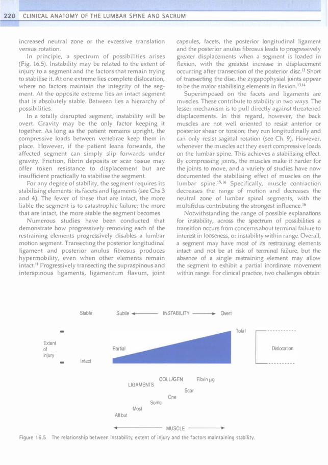
220 CLINICAL ANATOMY OF THE LUMBAR SPINE AND SACRUM L
increased neutral zone Or the excessive translation verSliS rotation.
In principle, a spectrum of possibilities arises (Fig. 16.5). Instability may be related to the extent of injury to a segment and the factors that remain trying to stabilise it. At one extreme lies complete dislocation, where no factors maintain the integrity of the segment. At the opposite extreme lies an intact segment that is absolutely stable. Between lies a hierarchy of possibilities.
In a totally disrupted segment, instability will be overt. Gravity may be the only factor keeping it together. As long as the patient remains upright, the compressive loads betw'een vertebrae keep them in place. However, if the patient leans forwards, the affccted segment can simply slip forwards under gravity. Friction, fibrin deposits or scar tissue may offer token resistance to displacement but are insufficient practically to stabilise the segment.
For any degree of stability, the segment requires its stabilising elements: its facets and ligaments (see ehs 3 and 4). The fewer of these that are intact, the more liable the segment is to catastrophic failure; the more that are intact, the more stable the segment becomes.
Numerous studies have been conducted that demonstrate how progressively removing each of the restraining elements progressively disables a lumbar motion segment. Transecting the posterior longitudinal ligament and posterior anulus fibrosus produces hypermobility, even when other elements remain intact.11 Progressively transccting the supraspinous and interspinous ligaments, ligamentum flavum, joint
capsules, facets, the posterior longitudinal ligament and the posterior anulus fibrosus leads to progressively greater displacements when a segment is loaded in flexion, with the greatest increase in displacement occurring after transection of the posterior disc.12 Short of transecting the disc, the zygapophysial jOints appear to be the major stabilising elements in flexion.11.1-'
Superimposed on the facets and ligaments are muscles. These contribute to stability in h.-vo ways. The lesser mechanism is to pull directly against threatened displacements. In this regard, however, the back muscles are not well oriented to resist anterior or posterior shear or torsion; they run longitudinally and can only resist sagittal rotation (sec Ch. 9). However, whenever the muscles act they exert compressive loads on the lumbar spine. This achieves a stabilising effect. By compressing joints, the muscles make it harder for the joints to move, and a variety of studies have now documented the stabilising effect of muscles on the lumbar spine.I'ufo Specifically, muscle contraction decreases the range of motion and decreases the neutral zone of lumbar spinal segments, with the multifidus contributing the strongest influence. It!
Notwithstanding the range of possible explanations for instability, across the spectrum of possibilities a transition occurs from concerns about terminal faiJure to interest in looseness, or instability within range. Overall, a segment may have most of its restraining elements intact and not be at risk of terminal faUure, but the absence of a single restraining element may allow the segment to exhibit a partial inordinate movement within range. For clinical practice, two challcnges obtain:
Stable Subtre • INSTABILITY Overl
- Total
Extent 01 Injury
- Intact
COLLAGEN LIGAMENTS
Fibnn �g
Scar One
Some Most
AlIbu1
MUSCLE
Figun� 16.5 Th� r�latjonship b�tw��n instability. �xt�nt of injury and th� factors maintaining stability.

• Overt failure or impending failure is readily rccognised radiographjcaUy in conditions such as fracture·dislocation when a vertebra exhibits malposition or an excessive motion apparent to the unaided eye. In such circumstances, instability is beyond doubt because the evident motion could not possibly have occurred unless the restraining elements were totally disrupted. However, the challenge obtains to determjne the threshold for instability when the abnormal motion is not readily apparent.
• For instability within range, the challenge is to demonstrate its presence and to be certain that the abnormal motion is responsible for the patient's symptoms.
HYPOTHETICAL MODELS
The concepts offered by biomechanists can be collated and summarised graphically using a unifying device: a force and displacement graph (Fig. 16.6). For any lumbar movement there will be a force that induces displacement. Acting against this force will be restrain-
DF
C � E
j � u '" � �
+ is
Time
Figure ' 6.6 A force and displacement diagram. The difference between displacing forces (OF) and restraining forces (RF) results in displacement of a motion segment. The slope of the displacement curve is the velocity of movement. In a normal coordinated movement, the velocity curve is smooth and regular. Towards the end of range, the velocity slows to zero as movement is arrested.
Instability 221
ing forces that stem from the facets, ligaments and muscles of the segment. These restraining forces act to prevent uncontrolled acceleration of the segment, under gravity for example. Given an appropriate combination of displacing forces and restraining forces, motion occurs; djsplacement progresses with time, and a velocity of motion emerges. The graph (see Fig. 16.6) shows the two opposing sets of forces and the change of displacement. The slope of this latter curve will be the velocity of movement. Under normal conditions, as displacing forces build up, the segment accelerates. As long as displacing forces exceed the restraining forces, movement continues. Towards the end of range, restraining forces exceed the displacing forces and movement decelerates, eventually stopping at end of range.
If a segment suffers a loss of stiffness, the restraining forces that resist forward flexion are reduced, but the gravitational forces that produce forward bending are unaltered and displacing forces remain the same (Fig. 16.7). As a result, the acceleration and eventual velocity of the resultant movement must, prima facie, be greater. lnstability ensues if the balance betvveen the displacing and restraining forces is insufficient to
j +
. . . . ' ..
DF
AF •••
••
••
••
•
•••
• ........ .
C � E � u '" � � is
Time
Figure ' 6.7 A force and displacement diagram of a motion segment with decreased stiffness. Throughout the range, the restraining forces (RF) are considerably less than the displacing forces (OF) and the segment develops a higher than normal velocity towards end of range. For comparison, the normal curves for restraining forces and displacement {see Fig. 16.6} are shown as dotted lines.
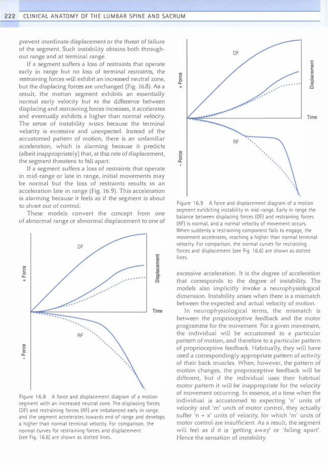
222 CLINICAL ANATOMY OF THE LUMBAR SPINE AND SACRUM
prevent inordinate displacement or the threat of failure of the segment. Such instability obtains both throughout range and at terminal range.
U a segment suffers a loss of restraints that operate early in range but no loss of terminal restraints, the restraining forces will exhibit an increased neutral zone, but the displacing forces are unchanged (Fig. 16.8). As a result, the motion segment exhibits an essentially normal early velocity but as the difference between displacing and restraining forces increases, it accelerates and eventuaUy exhibits a higher than normal velOCity. The sense of instability arises because the terminal velocity is excessive and unexpected. Lnstead of the accustomed pattern of motion, there is an unfamiliar acceleration, which is alarming because it predicts (albeit inappropriately) that, at this rate of displacement, the segment threatens to faU apart.
If a segment suffers a loss of restraints that operate in mid-range or late in range, initial movements may be normal but the loss of restraints results in an acceleration late in range (Fig. 16.9). This acceleration is alarming because it feels as if the segment is about to shoot out of control.
These models convert the concept from one of abnormal range or abnormal displacement to one of
i •
. -' .
i ,
.. . ...
OF
Time
Figure 16.8 A force and displacement diagram of a motion segment with an increased neutral zone. The displacing forces (OF) and restraining forces (RF) are imbalanced early in range, and the segment accelerates towards end of range and develops a higher than normal terminal velocity. For comparison, the normal curves for restraining forces and displacement (see Fig. 16.6) are shown as dotted lines.
...
RF
..... .' . 1 is
Time
Figure 16.9 A force and displacement diagram of a motion segment exhibiting instability in mid-range. Early in range the balance between displacing forces (OF) and restraining forces (RF) is normal, and a normal velocity of movement occurs. When suddenly a restraining component fails to engage, the movement accelerates, reaching a higher than normal terminal velocity. For comparison, the normal CUNts for restraining forces and displacement (see Fig. 16.6) are shown as dotted lines.
excessive acceleration. Jt is the degree of acceleration that corresponds to the degree of instability. The models also implicitly invoke a neurophy siological dimension. Instability arises when there is a mismatch between the expected and actual velocity of motion.
In neurophysiological terms, the mismatch is between the proprioceptive feedback and the motor programme for the movement. For a given movement, the individual will be accustomed to a particular pattern of motion, and therefore to a particular pattern of proprioceptive feedback. Habitually, they will have used a correspondingly appropriate pattern of activity of their back muscles. When, however, the pattern of motion changes, the proprioceptive feedback will be different, but if the individual uses their habitual motor pattern it will be inappropriate for the velocity of movement occurring. tn essence, at a time when the individual is accustomed to expecting 'n' units of velocity and 'm' units of motor control, they actually suffer 'n + x' units of velocity, for which 'm' un.its of motor control are insufficient. As a result, the segment will feel as if it is 'getting away' or 'falling apart'. Hence the sensation of instability.

There is no guarantee that the nervous system can adapt to changes in the behaviour of mechanical constraints, other than in a crude way. The changes in motion occur too quickly for the proprioceptive feedback to correct the motor activity by reflex. [nstead, warned of the unaccustomed acceleration, the nervous sy stem recruits a sudden muscle contraction, as if to deal with an 'emergency'. Clinically, this would manifest as a jerk or a 'catch'. Otherwise, in a very unstable segment, muscles may be persistently active to guard the affected segment against any movement that risks accelerating the segment.
In terms of these models, how instability relates to pain is a vexatious issue. Notionally, a hy permobile segment, or one with loss of stiffness, should not be painful. Pain might occur only at end of range when restraints were being excessively strained. If the loss of stiffness is due to injury, pain may arise from the injured structures, but in this regard the pain is independent of the instability; the pain may be aggravated by the movement, not because of instability but simply because the injured part is being irritated.
Segments with an increased neutral zone or with mid-range loss of restraints exhibit a marked terminal acceleration. A model that might explain pain under these circumstances invokes what might be referred to as abnormal 'attack'. Normally, terminal restraints in a segment would be engaged at a normal, accustomed velocity. However, in an unstable segment, these restraints will be engaged, or 'attacked', at a greater than normal velocity. Perhaps the more forceful attack on these restraints stimulates nociceptors in them.
However, notwithstanding these speculations, it may well be that there is no need to explain the pain of instability because there is no direct relationship. Pain may arise from a segment simply because it is injured. Instability may be present but in parallel. Movement is painful as in any painful segment. But if the movement is suddenJy jerked or arrested, the sudden compression load exerted by the back muscles might be the aggravating factor for the pain, rather than a painful engagement of restraints.
CLINICAL INSTABILITY
Almost antithetical to the biomechanists' notion of instability is the concept of 'clinical instability'. Two uses of this latter term obtain.
One use is explicitly clinical and temporal; it bears no relationship to biomechanics. It maintains that clinical instability is a condition in which the clinical status of a patient with back problems steps, with the least provocation, from the mildly sy mptomatic to the
Instability 223
severe episode. J1 Philosophically and semantically this does amount to instability in the sense that a trivial force causes a major displacement, but the displacement is not of a mechanical entity; it is a displacement of the patient's symptoms or of their clinical course. This use of the term is akin to speaking of an individual's mood or emotions being 'unstable'. This use of the term should not be confused or equated with the biomechanical use. More seriously, because it lacks any relationship to biomechanics, a diagnosis of clinical instability does not suggest, let alone indicate, mechanical therapy. There is a risk that, because 'clinical instability' and 'biomechanical instability ' sound alike, they are equivalent. They are not.
A second definition of clinical instability has a more evident and legitimate relationship to biomechanics. It refers to biomechanical instability that reaches clinical significance, in that it produces symptoms. In this regard, the clinical features are immaterial to the basic definition; the definition rests on biomechanical abnormalities. The addition of the adjective 'clinical' simply promotes the biomechanical instability to one of ostensible clinical relevance. However, and most particularly, it does not imply that the instability is clinical evident; it implies only that the instability is clinically relevant.
The diagnosis of instability still hinges on biomechanical tests.
DIAGNOSIS
lnstability is readily abused as a diagnostic rubric. It is easy to say a patient has instability; it is much harder to satisfy any criteria that justify the use of this term.
Most irresponsible in this regard is the fashion to label as instability any spinal pain that is aggravated by movement. This is patently flawed. Conditions can occur which are painful and which are aggravated by movement but which involve no instability of the spine. The movements of the affected segment are normal in quality and in range; they are not excessive. Indeed, the range of movement may be restricted rather than excessive. For example, a septic arthritis is
very painful, and any movement may aggravate the pain, but the joint and its segment are essentially intact and there is no risk of them falling apart. Osteoarthritis may be painful and aggravated by movements, and if anything, the joint is stiffer and more stable than normal.
U an anatomic or pathological diagnosis is available, it should be used, but 'instability' is not an arbitrary alternative that can be applied when no other diagnosis is apparent. Instability is clearly a biomechanical term

224 CLINICAL ANATOMY OF THE LUMBAR SPINE ANO SACRUM
and if it is to be applied, a biomechanical criterion must be satisfied. Pain on movement is not that criterion.
Criteria
Various authorities have issued guidelines for the legitimate use of the term instability.lu8 The major categories are shown in Table 16.1. Categories I, II and IU are beyond controversy. Each involves a condition that threatens the integrity of the spine and which can be objectively diagnosed by medical imaging, perhaps supplemented by biopsy.
Spondylolisthesis is a controversial category. Traditionally, the appearance of this condition has been interpreted as threatening. Even under normal circumstances, the L5 vertebra appears to be precariously perched on the sloping upper surface of the sacrum. Defects in the posterior elements, notably pars interarticularis fractures, threaten to allow the L5 vertebra to slip progressively across the sacrum. However, the available data mitigate against this fear.
Spondylolisthesis rarely progresses in adults" or teenagers,20 and therefore it appears inherently stable, despite its threatening appearance. Indeed, biplanar radiography studies of moving patients have shown that, if anything, grade 1 and grade 2 spondylolisthesis are associated with reduced range of motion rather than instabiHty.21 However, some patients with spondylolisthesis may exhibit forward slipping upon standing from a lying position,22 but it is not clear whether the extent of slip in such cases is abnormal. Studics, using implanted tantalum baUs in order to establish landmarks accurately, have found no evidence of instability.23 In some patients, movement abnormalities may be revealed using special radiographic techniques, which include having the patient stand loaded with a 20 kg pack and hanging by their hands from an overhead bar.2"-25 These extreme measures, however, have been criticised as unrealistic and cumbersome.1t
It is with respect to degenerative instability that the greatest difficulties arise. A classification system of this category of lumbar instability has been proposed (Box 16.1).8,18 The secondary instabilities are easy to
Table 16.1 Lumbar segmental instabilities
Category Causes
Fractures and fracture-dislocations II Infections of the anterior elements III Neoplasms IV Spondylolisthesis V Degenerative
Box 16.1 Degenentlve lumbar instabilities
• Primary • axial rotational
• translational
• retrolisthetic • scoliotic • internal disc disruption
• Secondary
• post-disc excision
• post-laminectomy
• post-fusion
accept and understand. They involve surgical destruction of one or more of the restraining elements of the spine, and are thereby readily diagnosed on the basis of prior surgery and subsequent excessive or abnormal motion. It is the primary instabilities that pose the greatest difficulties.
Rotational instability has been described as a hypothetical entity.26 Based on clinical intuition, certain qualitative radiographic signs have been described17 but their normal limits have not been defined, nor has their reliability or validity been determined. Consequently, rotational instability remains only a hypothetical entity.
Translational instability is perhaps the most classic of all putative instabilities. It is characterised by excessive anterior translation of a vertebra during flexion of the lumbar spine. However, anterior translation is a normal component of flexion (see Ch. 8). The difficulty that arises is setting an upper limit of normal translation. Posner et al.12 prescribed a limit of 2.3 mm or 8% of the length of the vertebral endplate for the L1 to L4 vertebrae, and 1.6 m.m or 6% for the L5 vertebra. Boden and Wiesej27 however, demonstrated that many asymptomatic individuals exhibited static slips of such magnitude, and emphasised that, in the first instance, any slip should be dynamic before instability could be considered. A dynamic slip is one that is evident in full flexion but not in extension, or vice versa. Furthermore, even dynamiC slips of up to 3 m.m can occur in asymptomatic individuals; only 5% of an asymptomatic population exhibited slips greater than 3 mm. Accordingly, Boden and Wiesel27 have advocated that 3 mm should be the threshold limit for diagnosing anterior translational instability. Hayes et al.,28 however, found that 4 mm of translation occurred in 20% of their asymptomatic patients. Accordingly, 4 mm might be a better threshold limit.

Belief in ret-rolisthetic instability dates to the work of Knutsson.:N He maintained that degenerative discs exhibited instability in the form of abnormal motions, notably retrolisthesis upon extension of the lumbar spine. This contention, however, was subsequently disproved when it was shown that similar appearances occurred in asymptomatic individuals.2II.JO As a result, there are no operational criteria for instability due to retrolisthesis, other than the guidelines of Boden and Wiesel27 or Hayes et al.,211 which state that up to 3 mm or 4 mm of translation can be normal .
Scoliotic instability amounts to no more than rotational instability or tran!>lational instability, alone or i.n combination, in a patient who happens to have scoliosis. Adding the adjective 'scoliotic' in no way changes the difficulties in defining and satisfying the diagnostic criteria for these putative instabilities.
There is no evidence, to date, that internal disc disruption is associated with instability. Radiographic biomechanical studies simply have not been conducted on patients with proven internal disc disruption.
Although positive correlations are lacking between disc degeneration and retrolisthetic rotational and translational instability, there are associations between disc degeneration and a raised instability (3ctor,1O Patients with disc degeneration exhibit a greater mean value oC instability factor that is statistically significant (Fig. 16.10). However, because the technique for determining the instability factor is very demanding and time consuming, this method of studying instability has not been pursued further, to date.
N=1 2 N=IO
N
20 25 30 35 40 45 IF
Figure 16.10 The distribution of values of instability factor in a normal population and a populatIon of patients with degenerative disc disease. (Based on Weiler et al. 1990.10)
Instability 225
Clinical diagnosis
Various clinical criteria have been proclaimed as indicative or diagnostic of lumbar instability.17.J1�12 At best, these constitute fancy. To be valid, clinical signs have to be validated against a criterion standard. The only available criterion standard for instability is offered by radiographic signs, but the radiographic signs of instability are themselves beset with difficulties. Consequently, no studies have yet validated any of the proclaimed c1in.ical signs of instability.
SUMMARY
lnstability is a biomechanical term. Biomechanists have offered three distinct definitions of instability. One invokes decreased resistance to movement; the second invokes an increased neutral zone; and the third invokes altered ratios behveen translation and rotation. The first pertains to terminal instability while the latter two refer to instabihty within a normal range of motion.
The anatomical substrate for instability is damage to one or more of the restraining elements of the lumbar spine. For major types of instability, substantial damage to these elements is usually obvious radiographically. However, the anatomical basis for more subtle forms of instability remains elusive, as is the case for increased neutral zone or increased instability factor.
The diagnosis of major types of instability is relatively straightforward and relies on overt radiographk features. What remains contentious is whether or not so-called degenerative spinal disorders are associated with instability, and whether this type of instability can be diagnosed. There are no operational criteria for rotational and retrolisthetic instability. Operational criteria are available only for translational instability. The criteria for instability factor have been tested in onJy one study. There are no validated clinical signs by which instability might be diagnosed.
It is perhaps lamentable that for an entity that has attracted so much clinical attention, there is so little basis for its \'alid diagnosis. Nevertheless, the concepts of increased neutral zone and instability factor provide a likely explanation of what clinicians believe they have been diagnosing in patients who seem to suffer instability but who lack signs of overt instability. The challenge remains to correlate clinical wisdom with demonstrable radiographic biomechanical signs.

226 CLINICAL ANATOMY OF THE LUMBAR SPINE AND SACRUM
References
I. Nachemson AL. Lnstability of the lumbar spine: pathology, treatment, and clinical evaluation. Neurosurg Clin North Am 1991; 2:785-790.
2. Pope MH, Frymoyer JW, Krag MH. Diagnosing instability. C1in Olthop 1992; 279:60-67.
3. Kirkaidy-Willis WHo Presidential symposium on instability of the lumbar spine: introduction. Spine 1985;
10:254.
4. Nachemson A. Lumbar spine instabilHy: a critical update and symposium summary. Spine 1985;
10:29()...291.
5. Wiesel S. Editor's comer. Semin Spine Surg 1991; 3:91.
6. Ashlon-MiUer lA, Schultz AB. Spine instability and segmental hypermobility biomechanics: a call for the definition and standard use of terms. Semin Spine Surg 1991; 3:136-148.
7. Pope MH, Panjabi M. Biomechanical definitions of spin"ll instability. Spine 1985; 10:255-256.
8. Frymoycr JW, Pope MH. Segmental instability. Semin Spine Surg 1991; 3:1W-1I8.
9. Panjabi MM. The stabilizing system of the spine. Part n. Neutral zone and instability hypothesis. } Spinal Disord 1992; 5:390-397.
10. Weiler P}, King GJ, Gertzbein SO. Analysis of sagittal plane instability of the lumbar spine in vivo. Spine 1990;
15:1300-1306.
It. Akkerveeken PF, O'Brien}p, Pari WM. Experimentally induced hypermobUHy in the lumbar spine: a pathologic and radiologic study of the posterior ligament and annulus fibrosus. Spine 1979; 4:236-241.
12. Posner I, White AA, Edwards wr et a!. A biomechanical analysis of the clinical stability of the lumbar and lumbosacral spine. Spine 1982; 7:374-389.
13. Abumi K, Panjabi MM, Kramer KM et al. Biomechanical evaluation of lumbar spinal stability after graded facetectomies. Spine 1990; 15:1142-1147.
14. Pintar FA, Cusick JF, Yoganandan N et a!. The biomechanics of lumbar facetectomy under compressionwOexion. Spine 1992; 17:804-810.
15. Panjabi M, Abumi K, Duranceau J et al. Spinal stability and intersegmental muscle forces: a biomechanical model. Spine 1989; 14:194-200.
16. Wilke H}, Wolf S, Claes LE et al. Stability increase of the lumbar spine with different muscle groups: a biomechanical i" vitro study. Spine 1995; 20:192-198.
17. KirkaJdywWtllis WH, Farfan HE Instability of the lumbar spine. Oin Orthop 1982; 165:110-123.
18. Hazlett jW, Kinnard P. Lumbar apophyseal process excision and spinal instability. Spine 1982; 7:171-176.
19. Fredrickson BE, Baker 0, McHoLick WJ et al. The natural hjstory of spondylosis and spondylolisthesis. J Bone Joint Surg 1984; 66A:699-707.
20. Danielson 81. Frennered AK, Irstam LKH. Radiologic progression of isthmic lumbar spondylolisthesis in young patients. Spine 1991; 16:422-425.
21. Pearcy M, Shepherd J. Is there instability in spondylolisthesis? Spine 1985; 1O:175-ln.
22. Lowe RW, Hayes TO, Kaye J et a1. Standing roentgenograms in spondylolisthesis. Clin Orthop 1976;
117:80-84.
23. Axeisson P. Johnsson R, Stromqvist B. Is there increased intervertebral mobility in isthmic adult spondylolisthesis? A matched comparative study using roentgen stereophotogrammetry. Spine 2CXX>; 25:1701-1703.
24. Friberg O. Lumbar instability: a dynamic approach by traction-<ompression radiography. Spine 1987;
12:119-129.
25. Kalebo P, Kadziolka R, Sward L. Compression-traction radiography of lumbar segmental instability. Spine 1990;
15:35 1-355.
26. Farfan HF, Gracovetsky S. The nature of instability. Spine 1984; 9:714-719.
27. Boden SO, Wiesel SW. lumbosacral segmental motion in normal individuals. I-lave we been measuring instability properly? Spine 1990; 15:571-576.
28. Hayes MA, Howard TC, Gruel CR et al. RoentgenographiC evaluation of lumbar spine Oexion-extension in asymptomatic individuals. Spine 1989; 14:327-331.
29. Knutsson F. The instability associated with disk degeneration in the lumbar spine. Acta Radiol 190M;
25:59�.
30. La Rocca H, MacNab I. Value of pre-employment radiographic assessment of the lumbar spine. Ind Med Surg 1970; 39:31-36.
31. Grieve GP. lumbar instability. In: Grieve G. (>d. Modem Manual Therapy of the Vertebral Column. Edinburgh: Churchill Livingstone; 1986: 416--441.
32. Paris SV. Physical signs of instability. Spine 1985;
10:277-279.

Chapter 17
Radiographic anatomy
CHAPTER CONTENTS
Ulteral view 227
Relations 228
Posteroanterior view 231
Relations 233 Other views 234
L - --- --------------�
Few practitioners get to see the lumbar spine directly. That privilege is restricted to anatomists and to some surgeons. Occasionally, pathologists may elect to examine the lumbar spine.
AU practitioners, however, are likely to have access to imaging studies of their patients. Depending on the modality used, imaging studies depict various elements of the lumbar spine to greater or lesser degrees. Plain radiography will depict the bones of the lumbar spine. cr provides images of the vertebrae, and images of the muscles, vessels and nerves to a certain extent. MRJ provides images of the shape and internal structure of bones, disc, joints, muscles, vessels and nerves.
Many radiologists achieve competence in reading images by repetition and experience while other practitioners do not have the opportunity to acquire that experience. Consequently, radiology becomes somewhat of a mystery or chalJenge to them.
However, competence in reading images can be achieved in another way than by repeated. experience. It can be called 'Anatomy by Expectation'. Instead of learning what every shadow on a radiograph represents, practitioners can use their knowledge of anatomy to predict and anticipate what should be evident in the image.
A comprehensive description of this method has hoen produced, in CD fonnat, by the International Spinal Intervention Society.' The CD covers plain radiography, and progresses to axial, coronal and sagittal views on MRl. This chapter provides a synopsis of that material with respect to plain radiography.
LATERAL VIEW
In preparation for viewing a lateral radiograph of the lumbar spine, the practitioner should anticipate, and
227

228 CLINICAL ANATOMY OF THE LUMBAR SPINE ANO SACRUM
prepare, what they expect to encounter, for example as illustrated in Figures 1.2A and 1.3 (pp 4 and 5).
They should expect to see five vertebral bodies, each with flat top and bottom surfaces, a straight posterior border and a concave anterior surface (Fig. 17.1). From the back of the vertebral body they should expect a pedicle projecting posteriorly. Hanging downwards from the pedicle they should expect a lamina. In a lateral view, the lamina will not be a square plate but will appear as a narrow plate seen edge on. Posteriorly from the plate they should expect the axe-shaped profile of the spinous process. Inferiorly from the lamina they should expect the oval outline of the inferior articular process. Superiorly from the pedicle they should expect the superior articular process.
When practitioners view a lateral radiograph, they should not try to recognise what they see (Fig. 17.2A). Lnstead, they should project onto the radiograph what they expect should be there (Fig. 17.26).
They should repeat the projection for each of the five lumbar vertebrae (Fig. 17.2C). In doing so, they should realise that the outlines of inferior and superior articular processes overlap. If practitioners understand the structure of the lumbar zygapophysial joints (see Ch. 3), they should realise that, on a lateral radiograph, the silhouette of the inferior articular process projects medial to that of the superior articular process.
The hardest structure to find on a lateral radiograph is the transverse process. It is with respect to this structure that Anatomy by Expectation comes to the fore. On a radiograph, the transverse processes are
"
Transverse process
Lamina
SpII'lOUS process
indistinct; and viewers could be forgiven for not seeing any trace of the transverse processes. However, Anatomy by Expectation indicates where the transverse processes should be (see Fig. 1.2A, p. 4).
tn a lateral radiograph, each transverse process projects towards the viewer. Hence it is seen end on. Moreover, its tip is usually not visible because it is obscured by the radiographic densities of other parts of the vertebra, which are superimposed on it. However, what will be visible is the silhouette of the flared base of the transverse process. At each segmental level, the base of the transverse process will lie opposite the posterior end of the pedicle. In this region, the base will appear as an ellipsoidal shadow (Fig. 17.2D).
At LS, the transverse process has a broader base, which extends onto the vertebral body (see Ch. 1). So, locating the L5 transverse process involves exploring the entire length of the pedicle.
Relations
Plain radiographs depict only bones; they do not demonstrate other structures or tissues. However, a knowledge of the anatomy of those structures, and their relationship to the vertebrae, allows their location to be plotted, once the bones have been identified.
tn lateral views, the lumbar spinal nerves are located in the intervertebral foramina. As described in Chapters 5 and 10, they are located high in the foramina, below the pedicle and behind the lower end of the vertebral body and, therefore, above the level of the intervertebral disc (Fig. 17.3A). Once the spinal
Supenor artICular process
Ped<l.
Vertebral body
Inferior articular process
Figure' 7.1 A sketch of the lateral appearance of a lumbar vertebra.

Radiographic anatomy 229
..... � .. \. , ;
.............. �
Figure 11.2 Interpreting a lateral radiograph of the lumbar spine. (Al Unmarked, lateral radiograph. (8) Radiograph in which the expected outline of a lumbar vertebra has been registered on the LJ vertebra. (el Radiograph on which the outlines of all five lumbar vertebrae have been superimposed. (D) Radiograph in which tracings of the bases of the transverse processes have been added.

230 CLINICAL ANATOMY OF THE LUMBAR SPINE AND SACRUM
nerves have been located, the course of their branches can be projected (Fig. 17.38). The ventral rami pass downwards and forwards from the spinal nerves, entering the muscle compartment anterior to the transverse processes (see Ch. 10). The dorsal rami pass backwards and downwards. The medial branch crosses the neck of the superior articular process, behind the transverse process. Since it is intimately related to bone, the course of the medial branch can be depicted with confidence, once the relevant bony elements have been identified. The lateral branches and intermediate branches have no bony relations. Therefore, their course cannot be depicted with certainty. EssentiaUy, however, they pass behind the transverse processes into the posterior back muscles (see Ch. 10).
Practitioners should also be able to superimpose on lateral views the location and disposition of the various muscles of the lumbar spine (see Ch. 9). With detailed knowledge of the fascicular anatomy of these muscles, practitioners could plot the attachments and
orientation of every fascicle.2-4 For practical purposes, however, such precision is excessive. Instead, practitioners could be satisfied if they realise that:
1. Beside the vertebral bodies, in front of the transverse processes, fascicles of the psoas major muscle arise from the transverse processes and the intervertebral discs, and aggregate longitudinally, in a descending fashion, to form the body of the muscle (Fig. 17.4).
2. Various fascicles of multifidus run caudoventrally between the spinous and mamillary processes, as well as onto the sacrum (see Fig. 17.4).
3. The multifidus will be flanked by the lumbar fibres of longissimus lumborum passing rostroventrally to the transverse process (see Fig. 17.4).
The same line of reasoning could be continued to add the iliocostalis flanking the longissimus, the erector spinae aponeurosis covering all of the posterior muscles, and the quadratus lumborum lying beside the psoas.1
Figure 17.3 A lateral radiograph of the lumbar spine on which its neural relations have been dl'3wn. (A) The spinal nerves, in the intervertebral foramina, are depicted. (8) From the spinal nerves, the ventral rami (VR) and dorsal rami (dr) have been depicted.

Figure 17.4 A lateral radiograph of the lumbar spine, on which tracings of the related muscles have been superimposed. L longissimus; M, multifidus; P. psoas.
POSTEROANTERIOR VIEW
Posteroanterior radiographs of the lumbar spine present difficulties in recognition because the shadows of several elements are superimposed on one another. This can be overcome by knowing what to expect, and dividing the exercise into anticipating anterior elements and posterior elements.
Practitioners should expect to see a lumbar vertebral body, at each segmental level. In posterior view, the vertebral body presents as a rectangle, with flat top and bottom surfaces and concave lateral margins (Fig. 17.5A). Furthermore, projecting towards the viewer will be dense ovoid silhouettes that represent the pedicles seen end on.
For the posterior elements, practitioners should expect to see a complex shape, not unlike a butterfly (Fig. 17.56). The centre of the shape will be formed by the lami.nae of each Side, joined in the midline. Together they form a quadrangular plate, with concave superior, inferior and lateral margins. The
Radiographic anatomy 231
superior lateral comers of the plate will be registered over the ends of the pedicles on each side.
From the superior lateral corner, practitioners should expect the superior articular process projecting upwands, like a mitten facing medially. From the inferior lateral corner, they should expect the inferior articular process projecting inferiorly, and looking like the profile of a spoon facing laterally.
From the junction of the laminae, in the midline, practitioners should expect the spinous process seen end on, projecting towards them. Finally, they should expect the transverse process on each side projecting laterally from the superior lateral corner of the quadrangular plate.
With these expectations, practitioners can approach a posteroanterior radiograph of the lumbar spine (Fig. 17.6A). First, they should expect to encounter the simple rectangular outlines of the vertebral bodies with their pedicles. To perceive these in the radiograph, viewers should ignore everything else that does not look like a vertebral body (Fig. 17.66).
Finding the posterior elements is a more complex tas.k but only because of the irregularity of their appearance. The task is Simplified by approaching one segment at a time. At a middle lumbar segment, practitioners should look for where they can register the butterfly-shaped silhouette (Fig. 17.6C). Once they have done so, they can repeat the exercise at each of the remaining levels (Fig. 17.6D).
Once aU silhouettes of the posterior elements have been superimposed on the radiograph, practitioners should realise that the inferior and superior articular processes overlap. Where they overlap, the zygapophysial joints are formed. Sometimes, at some levels, a joint cavity wilJ be evident, between the medial surface of the superior articular process and the lateral surface of the inferior articular process (see Fig. 17.60). However, cavities will not always be evident. They will be apparent only in those joints whose plane is largely sagittal (see Ch. 3). If the plane of the jOint is oblique or coronal, a joint cavity will not be evident. Nevertheless, the joint cavity will be located in that region where the silhouettes of the inferior and superior articular processes overlap.
The L5 vertebra can cause difficulties for recognising either its anterior elements, its posterior elements or both. This arises because, often, the LS vertebra is inclined forwards, on a steep sacral angle (see Ch. 5). Therefore, in a posteroanterior radiograph L5 is not seen square on; it is seen obliquely, as if looking at it somewhat from below. Under those conditions, the top and bottom surfaces of the vertebral body are not seen as flat lines, as at other lumbar levels (see Fig. 17.66). Instead, those surfaces

232 CLIN ICAL ANATOMY OF THE LUMBAR SPINE AND SACRUM
\
A
B
Figure 17.5 Sk�tches of the appearance of a lumbar vertebra in posterior view. (A) The anterior elements, I.C:. vertebral body and pedicles. (8) The posterior elements.
Figure 17.6 Interpreting a posteroanterior radiograph of the lumbar spine. {Al Unmarked, PA radiograph. (B) Radiograph in which the expected outlines of the anterior elements have been registered on the respective vertebrae. lS appears unusual because it is tilted forwards and so is viewed somewhat from below. Its superior and inferior end plates assume an elliptical appearance, and the pedicles project upwards.

Radiographic anatomy 233
Figure 17.6 Cont'd (e) Radiograph on which the outline of the posterior elements has been registered on the 1.3 vertebra. (D) Radiograph on which the posterior elements of all five lumbar vertebrae have been superimposed. The zygapophysial joints lie where the inferior and superior articular pr�ses overlap but an actual joint cavity (zj) is evident only at the l2-LJ and l3-l4 levels in this example.
appear as transverse ellipses. Also, the pedicles do not face backwards, towards the viewer, but upwards and backwards. Meanwhile, the posterior elements are not directly behind the vertebral body but appear to be slightly above the level of the body (see Fig. 17.6D). Nevertheless, if these adaptations are expected and recognised, the elements of L5 can be found.
Relations
Having established the location of each of the bony elements, the practitioner can project where other structures should be located, even if they are not visible.
By focusing on the anterior elements, they can project where the spinal nerves and ventral rami should lie (see Chs 5 and 10). The nerve roots curve around the medial aspect of each pedicle, and from the spinal nerve immediately below the pedicle (Fig.
17.7A). Lateral to the intervertebral foramen, the spinal nerve continues as the ventral ramus.
By focusing on the posterior elements, the practitioner can project where the branches of the dOTS<11 rami run (Fig. 17.78). The medial branches curve around the base of the superior articular process (see Ch. 10). The lateral and intermediate branches descend obliquely laterally, across the proximal ends of the transverse processes.
The multifidus muscle covers the laminae of the lumbar vertebrae but expands laterally as it approaches and then covers the sacrum (Fig. 17.8). The longissimus thoracis pars lumborum is a narrow muscle, lateral to the multifidus, stemming from the accessory processes (see Ch. 9). Caudally, it inserts into the lumbar intermuscular aponeurosis, which separates it from the iliocostalis lumborum pars lumborum (sec Fig. 17.8).

234 CLINICAL ANATOMY OF THE LUMBAR SPINE AND SACRUM
Figurt: 17.7 Posteroanterior radiograph of the lumbar spine on which its neural relations have been drawn. (A) The spinal nerve and its roots, and the ventral rami. (8) The branches of the: dorsal rami. ib, intermediate: branch; Ib, lateral branch; m, medial branch.
OTHER VIEWS
Other, more complex views, such as the oblique view can be approached in a similar fashion. I The approach can also be extended to axial, coronal and sagittal views, as seen on CT or MRl.1 In all instances,
however, there is nothing in the radiography that should be oppressive. Reading the image can be reduced to asking what structures should be present, and anticipating what they should look like. Reading the image then becomes a simple matter of recognising what the practitioner expects to be there.

Figure 17.8 A posteroanterior radiograph of the lumbar spine. on which tracings of the related muscles have been superimposed. IC, iliocostalis; L. longissimus; UA, lumbar intermuscular aponeurosis; M, multifidus.
References
1. Bogduk N. Radiographic Anatomy of the Normal Lumbar Spine. CD-ROM. San Francisco: International Spinal Intervention Society; 2004.
2. Bogduk N, Pearcy M, Hadfield C. Anatomy and biomechanics of psoas major. Clin Biomech 1992; 7:109-119.
Radiographic anatomy 235
3. Macintosh JE, Bogduk N. The attachments of the lumbar erector spinae. Spine 1991; 16:783-792.
-t. Bogduk N, Macintosh JE, Pearcy MJ. A universal model of the lumbar back muscles in the upright position. Spine 1992; 17:897-913.
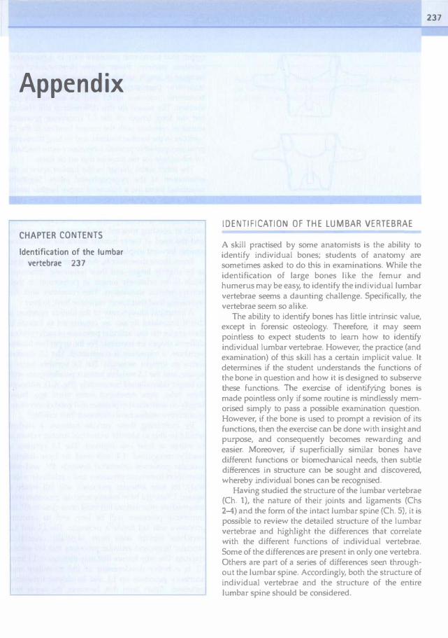
Appendix
�APTER CONTENTS
Id.ntification of the lumbar
vertebrae 237
IDENTIFICATION OF THE LUMBAR VERTEBRAE
A skill practised by some anatomists is the ability to identify indjvidual bones; students of anatomy are sometimes asked to do this in examinations. While the identification of large bones like the femur and humerus may be easy, to identify the individual lumbar vertebrae seems a daunting challenge. Specifically, the vertebrae seem so alike.
The ability to identify bones has little intrinsic value, except in forensic osteology. Therefore, it may seem pointless to expect students to learn how to identify ind.ividual lumbar vertebrae. However, the practice (and examination) of this skill has a certain implicit value. It determines if the student understands the functions of the bone in question and how it is designed to subserve these functions. The exercise of identifying bones is made pointless only if some routine is mindlessly memorised simply to pass a possible examination question. However, if the bone is used to prompt a revision of its functions, then the exercise can be done with insight and purpose, and consequently becomes rewarding and easier. Moreover, if superficially similar bones have different functions or biomechanica1 needs, then subUe differences in structure can be sought and discovered, whereby individual bones can be recognised.
Having studied the structure of the lumbar vertebrae (Ch. 1), the nature of their joints and ligaments (Chs 2�) and the form of the intact lumbar spine (Ch. 5), it is possible to review the detailed structure of the lumbar vertebrae and highlight the differences that correlate with the different functions of individual vertebrae. Some of the differences are present in only one vertebra. Others are part of a series of differences seen throughout the lumbar spine. Accordingly, both the structure of individua1 vertebrae and the structure of the entire lumbar spine should be considered.
237

238 CLINICAL ANATOMY OF THE LUMBAR SPINE AND SACRUM
11
l2
l3
L4
L5
Figur� A.l Identification of individual lumbar vertebr.lc. By
constructing four-sided figures around the tips of the articular
prOCfiStS of the lumbar vertebrae. distinguishing features are
revealed. The figures formed around the upper two lumbar vertebrae are trapezia; that around l3 is an upright rectangle; that around L4 is a square; and that around lS is a horizontal rectangle.
The most individual lumbar vertebra is the fifth. Its characteristic feature is the thickness of its transverse processes and their attachment along the whole length of the pedides as far as the vertebral body. Examining this feature serves to remind the student of the attachment of the powerful iliolumbar ligaments to the L5 transverse processes and their role in restraining the L5 vertebra. In tum, this is a reminder of the problem that L5 faces in staying in place on top of the sloping sacrum.
There are no absolute features that enable the other four lumbar vertebrae to be distinguished but there are relative differences that reflect trends evident along the lumbar spine. First, as a general rule, the lengths of the
upper four transverse processes vary in a reasonably constant pattern. From above downwards, they increase in length and then decrease such that the L3 transverse process is usually the longest, and the transverse processes of L1 and L4 are usually the shortest. The reason for this difference is still obscure but the long length of the L3 transverse processes seems to correlate with the central location of the L3 vertebra in the lumbar lordosis, and its long transverse processes probably provide a necessary extra mechani· cal advantage for the muscles that act on them.
The other serial change in the lumbar spine is the orientation of the zygapophysial joints. Sagittally orientated joints are a feature of upper lumbar levels, while joints orientated. closer to 45- are more char· acteristic of lower levels. Examining this feature selVes as a reminder of the compound role of the zygapophysial joints in resisting forward displacement and rotation, and the need at lower lumbar levels for stabilisation against forward displacement.
From above downwards, the vertebral bodies tend to be sUghtly larger, and their transverse dimension tends to be relatively longer in proportion to their anteroposterior dimension. This correlates with the increasing load that lower vertebrae have to bear.
A structural idjosyncrasy of the lumbar vertebrae is that if four·sided figures are constructed to include in their angles the four articular processes of each vertebra, different shapes are revealed.' For the upper two lumbar vertebrae, a trapezium is constructed. The L3 vertebra forms an upright rectangle. The L4 vertebra forms a square, and the L5 vertebra forms a paralJelogram with its longer sides aligned horizontally (Fig. A.l). Although these rules were developed some years ago, based largely on anatomical experience and good observation,' quantitative studies have confirmed their validity.2
By examining these various features, a student should be able to identify individual lumbar vertebrae to within at least one segment. The L.S vertebra is readily recognised. L4 will tend to have inferior articular processes orientated towards 45, and will have short transverse processes and a relatively wider body. Its four articular processes will fall inside a square. L3 should have inferior articular processes with intermediate orientations but most often close to 45'. Its transverse processes will be long and its articular processes will fall inside a rectangle. The L1 and L2 vertebrae remain with more sagittally orientated articular facets and articular processes that faU within trapezia. The only feature that may distinguish L 1 from L2 is a better development of the mamiLiary and accessory processes on L1 and its shorter transverse processes. Apart from this, however, the upper two lumbar vertebrae may be indistinguishable.

References
1. Fawcett E. A note on the identification of the lumbar vertebrae of man. J An.lt 1932; 66:384-386.
Appendix 239
2. Panjabi MM, OxJand T, Takata K et al. Articular facets of the human spine: quantitative three-.dimensionai anatomy. Spine 1993; 18:1298-1310.
•

Index
Notes pages numbers in bold refer to
tables or boxes pages numbers in italics refer to
figures
A
Acute locked back, 195 Age changes, 165-171
annulus fibrosus, 166,167 biochemical,166 collagen, 166 iliolumbar ligament, 45,105 intervertebral discs, 134, 157,
166-167 lamellae, t 67 mobility, 168-169 nucleus pulposus, 157, 166, 167 ossification, 154-156 sacroiliac jOint, 177-178 structural, 166--167 trabeculae, 167 vertebral body. 167-168 vertebral end plates. 14, 167 zygapophysiaJ joint, 84,160, 168
Agenesis, 161-162 Aggrecan, 15, 17 Ala, of sacrum, 60 Amphiarthroses, intervertebral see
Joints. interbody Angles
L1-Sl lordosis. 53 lumbolumbar lordotic, 53 lumbosacral lordotic, 53
Ankylosing spondylitis, 193 AnkylOSiS, sacroiliac joint, 178 Anterior sagittal rotation. 82, 83 Anterior sagittal translation,
82,83
Anulus fibrosus. 13, 13 age changes, 166, 167 axial compression, 77-78 axial distraction, 81 axial rotation, 85-86 axial rotation in flexion. 88 blood supply, 144 cartilage cells, 20 collagen. 13, 18-20, 39-40, 166 compression stiffness, 21 deformation, 21-22 development, 156 distortion, 24, 25 elastic fibres, 20, 166 fatigue fa.i1ure, 71 fibroblasts, 20 fissures, 162, 198-199, 199 flexion, 84 innervation, 134 lamellae buckling, 78 as ligament, 39-40, 40 lumbar lordosis, 53-5-1 microstructure, 19-20 nociception, 204 nutrition, 147 ossification, 169 osteophytes, 202 proteoglycans, 20 tears, 197-198, 198 tensile strength, 167 water content, 19, n weight�bearing, 21-22, 23, 80
AponeurosiS erector spinae, 107, 108-110. 109,
110,230 gluteus maximus, 110 latissimus dorsi, 111 lumbar intermuscular, 103, 104,
!O5, 192, 233 tendopathy,192
transversus abdominis, 110
ApophYSial joint see Zygapophysial joint
Arachnoid mater, 125 Arteries
anterior spinal canal, 142, 143, 144, 145
distal radicular, 146 dorsal proximal radicular, 146 equatOrial, 144 innervation, 133 intraosseous, 2 lumbar, 46, 141-142, 142 median sacral, 141 metaphysial. 142, 144. 145, 147
anastomosis, 142. 144, 145 nutrient, 2, 144,145 posterior spinal canal, 142 primary periosteal, 142, 144, 145 radicular, 142, 146, 146 ventral proximal radicular, 146
Arthritis osteoarthritis, 162, 19-1, 223 rheumatoid, 194 septic, 223 suppurative, 194
Articular tropism, 162-163 Athletes, 188,200 Autoimmune inflammatory response,
201 Axes
rotation, 64, 64 sagittal rotation, 91, 92-93
Axial compression, 77-81 Axial distraction, 81 Axial mesenchyme, 151-152, 152,
153 Axial rotation, 65--66, 85-86, 87
anulus fibrosus, 85-86, 88 biplanar radiography, 88 coupled movements, 89-90 fatigue failure, 87
241

242 CLINICAL ANATOMY OF THE LUMBER SPINE AND SACRUM
Axial rotation, (Confi,med) in flexion, 87-88 muscle strength, 114
Axial translation, 66
B
Baastrup's disease (kissing spines), 187-188, 207
Back muscles see Muscles Back pain see Pain Bending forces, 8 Biglycan, 19 Biomechanics. 63-75
axes of motion, 65, 66 creep set' Creep fatigue failure Si'e Fatigue failure forces. 72. 72-73 hysteresiS, 70, 70-71 initial range of movement, 69 instability. 217-219 lifting. 115-119 ligamentum flavum, 42 moments, n-73 movements see Movement(s) nucleus pulposus. 12 planes of movement, 64-66, 65 psoas major, 98 sacroiliac joint, 178-179, 179-180 stiffness, 68-69 stress-strain, 66-68 thoracolumbar fascia, 110-112
Biplanar radiography, 88, 178, 179 Bone pain, 187 Buttock pain, 184, 191. 193
c
Calcitonin gene-related peptide (CGRP), 130, 134, 188
Calcium ions. 147 Canal
radicular, 55, 56,127 sacraJ, 60-61, 61 vertebral, 54, 54-57, 124
boundaries, 55, 55, 126 shape, 56-57, 57 stenosis see Spinal stenosis
Carboxyl radicals, 16-17, 147 Cartilage
embryonic, 154 s.1croiliac joint. 175 vertebral endplate, 14 zygapophysial joint, 33, 34. 168
Cart-ilage cells (chondrocytes) annulus fibrosus. 20
nucleus pulposus, 12, 19 vertebraJ end plates, 20
Cartilaginous phase, 154 Catastrophic displacement. 218 Caudad, 66 Cauda equina, 124 Centre of reaction, 93, 93 Centrode of motion, 91-92, 92 Centrum, 152, 153, 155. 157-158 Cephalad, 66 Cerebrospinal fluid, 55,124,125, 147 Chloride ions, 147 Chondrification, 154, 154
zygapophysial joint, 160 Chondrification centres, '154 Chondrocytes see CartiJage cells Chondroitin sulphates. 14-15, IS, 166 Chondromalacia patellae, 194 Chorda reticulum, 156, 157 Coccygeal nerve roots, 124 Collagen, 17-19, 18
age changes, 166 anterior longitudinal ligament,
40-41 anuius fibrosus, 13, 18-20,39-40,
166 binding to proteoglycans, 19, 166 distribution, 18 failure, 67-68 fibrils, 17 interspinous ligaments, 43 intervertebral discs. 18--19, 166 lamellae. 13, 21 mechanical properties. 66-68 metabolism, 20 nucleus pulposus, 18--19, '19, 166 stress·strain curve, 67, 67-68 types, 17-19, 18 vertebral end plate, 20 zygapophysial joint, 33-34
Coll.genase (MMP-l). 19.20 CoHagen fibres, 17
crimped, 67 elasticity. 23 embryonic, 156 hysteresis, 70 stress·strain, 66-68, 67
Comparhnent syndrome, 190,207 Compression, 66
axial, 77-81 back muscles. 113--119 erector spinae, 114 injuries, 78 lumbar lordosis, 54, 80 spina 1 nerves, 57 strain, 66
Computed tomography (Cf), 162, 185. 195, 198, 204,205.234
Conus medullaris, 146 Core proteins, 15, 16 Cornua, 60 Coronal plane, 64 Coupled movement, 88-91, 89, 90 Creep. 69-70, 70, 168
axial compression, 78 axial distraction, 81 intervertebral discs, 78
Crimp, 67 Critical point, 113
o
Decorin, 19 Degenerative instability. 224, 224 Degenerative joint dise.lse, 169, 194 Dermatan sulphate, 19 Dermatomes, 131, 132, 154 Dermomyotome. 151, 153, 154 Development, 149-164 Developmental anomalies
nerve roots, 127-129, 128 vertebral, 161-163
Diaphragm, crura, 7, 41 Diffusion, 147-148 Discectomy, 78
range of movement. 91 Discitis, iatrogenic. 197 Discogenic pain, 162-163, 19S-2()..j.
disc stimulation. 196-197 pathology. 197
Discography. 162. 196-197. 198 Discometry,79, 113 Discs, intervertebral, 11-28
age changes, 134, 157.166-167 anulus fibrosus set Anulus fibrosus axial compression, 77-79. 78 ax,ial rotation. 85-86 biochemical changes, 166 biomechanics. 12, 23 bulging, 57 collagen. 18-19, 166 constituents, 14-19 creep, 78 degeneration. 162-163,202,202 degradation. 78, 201-202. 202 development, 153, 156-157, 157 energy store. 23 enzymes, 19 functions, 21-25 height changes, 78-79, 167.202 herniation set' Herniation immature, 16 innervation, 133-137, 135, 136
histology. 134 nerve ingrowth. 136-137

Discs. intervertebral, (Contil/ued) nerve plexus, 134, 134 sources, 134, 134-136
internal disruption see Intemal disc disruption
keratan sulphate/chrondroitin sulphate, 166
lactic acid, 20 lumbosacral, 51, 52 metabolism, 20-21, 21 microstructure, 19-20 movement, 23-25 narrowing, 167, 202-203 nucleus pulposus see Nucleus
pulposlls nutrition, 14, 20-21. 147-148 osteophytes, 57 oxygen content, 20, 147 pain, 19S-2Q.1 pH, 20 pressure increases, 25 pressure measurement
(discometry), 79, 113 Scleral, 61, 6'/ shock absorber, 23 structural changes. 166-167 structure, 12-14, 13 torsion, 85-86 torsion injury, 196, 197-198, 198 vertebral end plates see Endplates.
vertebral water binding, 166 water flux, 148 weight·bcaring, 11, 22.22-23
Distraction, 66 axial, 81 interbody joints. 23, 24. 26
Domain,16 Dural5<1c, 124,125, 126 Dural sleeve, 124, 125, 191 Dura mater, 125
E
fibrosis, 191 inflammation, 191 pain, 190-191, 207
Ectoderm, 149, 150 Elastic fibres
annulus fibrosus, 20, 166 interspinous ligaments, 43 ligamentum flavum, 42-43 nucleus pulposus, 19, 166 zygapophysial joint, 34
Elastin, 42 Elaunin,42 Electromyography, 103, 113, 189
Embryology, 149-164 Endoderm, 149, 150 Endplates, vertebral, 12, 13, 13-14, 14
age changes, 167 axial compression, 78, 80-81 blood supply, 1-14 cartilage, 14 cartilage cells, 20 collagen, 20 development, 158, 159 fractures, 71, 78, 168, 200-202, 201,
203,203 hyaline cartilage, 14 innervation, 136 microstructure, 20 neonatal, 14 nutrition, 14, 147 proteoglycans, 20 tears, 14 water content 20 weight-bearing, 22-23
Enzymes, 19 Epidural disorders, 185 Epidural fat, 127 Epidural space, 126 Epimere (epiaxial portion), 154 Epineurium, spinal nerve, 124, 124 Exercise, 148, 200 Extended domains, 15-16 Extension, 66, 85, 112
F
biplanar radiography, 88 coupled movements, 89 injuries, 194-195, 195 llmiting factors, 85, 85 moments, 114, 115 sacroiliac joint, 179, 179--180
Facet joint see Zygapophysia\ jOint Facets
articular, 3, 4, 29-33, 30 shape,29-30, JO,31, 32-33,33
inferior articular, 4, 32, 82, 86 superior articular, 4, 30, 32, 82
Facet syndrome, 193 Far out syndrome, 131 Fascia, thoracolumbar, 110--112
anterior layer, 110 biomechanics, 110--112 compartment syndrome, 190 deep lamina, 111-112 fat herniation, 190 function, 112-113 gain, 116 innervation, 130, 190 intertransverse ligament, 46
lateral raphe, 105, 110 lifting, 116-117, 117 middle layer, 110 pain, 190 posterior layer, 110--112, 111 superficial lamina, In supraspinous ligament, 44
Fast-hvitch fibres, 114 Fat
epidural, 127 herniation, 190, 207 laminae, 47
Index 243
superior articular recess, 46 zygapophysial joint, 33, 34, 35, 35
Fatigue failure, 71, 71-n annulus fibrosus, 71 axial compression, 80-81 axial rotation, 87
Fatigue resistance, 114 Fetus
iliolumbar ligament, 45 intervertebral discs metabolism,
20 sacroiliac joint, 177
Fibroblasts, 20, 147, 186 Fibrocartilage, 14 Fibronectin, 19 Fibrous ankylosis, 178 Flail segment, 188 Flexion, 66, 8 1--85, 82
anulus fibrosus, 84 axial rotation in, 87-88 biplanar radiography, 88 coupted movements, 89-90 failure, 84-85 forward see Forward nexion lateral see Lateral flexion lifting, 115 moments, 73, 73, 74, lt4, 115-116 muscle strength, 114 sacroiliac joint, 179, 179-180 shear forces, 114 zygapophysial joint, 82-83
Foramen, foramina anterior sacral, 59 intervertebral, S, 46, 55, 123 nutrient, 2 posterior sacral, 59, 60 vertebral, 3, 4, 54
Foraminal stenosis, 127, 185 Forces, 72, 72-73
bending, 8 direction of, 72, 73
Forward flexion (bending), 24-25, 82, 113
critical point, 113 iliolumbar ligament, 46 sacroiliac joint, 178

244 INDEX
Fon-yard translation, 82 Fractures
articular processes, 195 axial compression, 80 insufficiency, 174 pars interarticularis, 7, 85, 188 stress, 7 subchondral bone, 80, 195 trabeculae, 78. 80 vertebral body, SO, 187 vertebral endplale, 71, 78, 168,
200-202,201,203,203 zygapophysial joint, 195
G
Ganglion, dorsal root, 124 Gelatinase (MMP-2), 19 Globular domains, 15-16 Glucose, 147 Glycosaminoglycans (GAGs), 14-15,
3J Colgi tendon organs, 134 Gravity, n, 72, 112, 220 Grey rami communicantes, 132, 135,
135 Growth factors, 19 Gymnasts, 188
H
Haemopoiesis, 6 Height changes, 78-79, 167,202 Hemilamina,3 Hensen's node, 149 Herniation, 25, 162
rat, 190,207 inflammation, 190 intemal disc disruption, 203,
203 radicular pain, 185-186 range of motion, 91
Hip extensor muscles, 115, 117 Hip joint nexion, 179 Homeostasis, 19 Horizontal plane. 64 Hyaline cartilage, 14, 16 Hyaluronic acid, 15,15. 19 Hydraulic amplifier effect, 118 Hydroxylysine, 17 Hyperalgesia, 186 Hyperlordosis,53 Hypennobility, 91,193,218,220 Hypomere (hypaxial portion), 154 Ilysteresis, 70. 70-71
ageing, 168, 169
lliac crest syndrome, 192-193, 207 lliac fossa, 45 Ilium, 44, 174, 175-176 Infection
iatrogenic disci tis, 197 sacroiliac joint, 193 vertebral body, 187
lnflammation,185--186 autoimmune response, 201 spongiosa, 201
Initial range of movement, 69 Instability,217-226
anatomy, 219-221 biomechanics, 217-219 clinical,223 definition, 217-218 degenerative, 224, 224 diagnosis, 223-225, 224 hypothetical models, 221, 221-223 retrolisthetic,225 rotational, 224 scoliotic, 225 tenninal, 21�219 translational,224
lnstability ractor, 218-219, 225, 225 lnstantaneous ax.is of rotation (IAR),
91,91-93,93 lnterleukins.l86 Internal disc disruption (100),
198-204,207 aetiology, 200-204 clinical features, 204 compression inJUry, 203--204, 204 diagnosis, 204, 205 dose stresses, 199,200 fissures, 198-199 metabolism disturbance, 201-202 prevalence, 204 radial fissure grading, 19�199, 199 symptoms, 2().1
International Association of the Study or Pain (IASP)
back pain definitions, 183-184 International Spinal lnjection Society,
227 Intertransverse space, 46 Intervertebral discs see discs,
intervertebral Intra·abdominal balloon mechanism,
116 lntra-abdominal pressure, 116,
118-119 axial rotation, 11�119 lifting, 116 oblique abdominal muscle, 11�119 raised, 143
Intra·articu!ar haemorrhage, 195 Intraosseous hypertension, 187 Intrathecal anastomoses, 128-129 Ionic radicals, 16-17 Ischium, 174 Isolated disc resorption, 202
J
JOlOts apophysial see Zygapophysial Joint facet Sft Zygapophysial JOint interbody,10
bending/rocking. 24-25 design, 11, 12 movements, 23-25 resistance to movement, 24 sliding. 23-24, 24 twisllng, 25, 26 weight·bearing, 11-12
intervertebral, 9, 9-10 anterior Si'e Joints, interbody classification, 10, 10 posterior set! Zygapophysial
jOi.nt lumbosacral (1.5-51
zygapoph)'sial), 52, 60 neurocentral (neurocentra!
synchondrosis), 158 sacroiliac, 173-181
age changes, 177- 178 ankylOSis, 178 articulation, 61, 175-176 axes of movement, 119, 179, 180 biomechanics, 178-179,179-180 bones, 174, 174-175
K
capsule, 177 cartilage, 175 cavity, 174, 175 development, 177 extension, 119, 179-180 flexion, 179, 179-180 innervation, 177 ligaments, 176. 176-177,177 osteophytes, 178 pain, 193,205,207 stress·relieC, 173-174 structure, 174-177
zygapophysial �('t' Zygapophysial joint
Keratan sulphate, 15, 15. 16,166 Keratan sulphate/chrondroitin
sulphate (KS/CS raho), 166

Kissing spines (Baastrup's disease), 187-188,207
Koch's postulates, 186
l
Lactic acid, 20 Lamellae, 13, 13
age changes. 167 collagen fibres, 13.21 incomplete. 13,14,167 rupture. 25
laminae, 3, 4, 7 fal,47 function, 7 ossification. 156 PilfS interarticularis stt Pars
interarticularis plain radiography, 228, 228. 231,
232 sacrum, 60
Lammel impaction, 188 Laminar fibres, 101 Lamina slendens, 33 Lateral flexion (bending), 87, 112
coupled movements, 89-90 iliolumbar ligament, 46
Leg hfl, 1\3 Lolling, 113, ]]5, 115-119
hghl loads, 115-116 models, 1Ib-118
Ligaments, 39-49 alar-like, 111, 112 anterior iliolumbar, 44, 45. 54 anterior longitudinal. 40, 40-41, 41
development, 156 lumbar lordosis, 54, 80 tendinous section. 41 tension, 54, 80 weight-bearing. 80
anterior sacroiliac, 176, 17b, 177 of Bourgery, 46 dural, 127 failure, macroscopic, 68 false,4b-48 of Hofmann, 127 iliolumbar, 44-46, 45
age changes, 45, 105 children, 105 lumbar lordosis, 54 neonatal,45 pain, 192-193, 207
mferior corporotransverse, 47, 47 inferior iliolumbar, 44-45. 45 inferior transforaminal. 47. 47 inJUry, 70-71,162 interosseous sacroiliac. 176, 177
interspinous. 41, 43 axial rotation. 86 Baastrup's disease (kissing
spines), 187 compression, 187-188 flexion, 83-84 lumbosacral,52 pain, 192-193, 207
intertransverse, 4(J, 46. 46-47, 110 development, 154, ]54 pain, 191
lifting, 117 ligamentum flavum see
Ligamentum flavum long posterior sacroiliac, 176, 177 lumbar lordosis. 53-54 mamillo-accessory Ligament,
48,48 meningo\"crtebral. 127 midtransforaminal, 47, 47 pain, 191-193, 205 posterior elements, 42-44 posterior iliolumbar, 44, 45 posterior longitudinal, 41, 41, 42
development, 156 innervation. 191 pain, 191-192
posterior sacroiliac, 176 sacroiliac joint, 176, 176-177, 177 sacrospinous. t 76 sacrotuberous, 176-177 short posterior sacroiliac, 176 stabiUty,220 strain, 191 strength, 117-118, 118 stress-strain, 68. 68 superior corporotransverse.
47,47 superior iliolumbar, 44, 45 superior transforaminal, 47. 47 supraspinous, 41, 43-44
axial rotation, 86 flexion, 83-84 innervation, 130 moment, 117-118 pain, 191 tendinous fibres, 44
transforaminal, 47, 47--48 vertebral body, 39-41 vertical iliolumbar, 45. 45
Ligamentum flavum. 33, 41. 42-43, 43 buckJing, 57 elastin. 42--43 flexion, 83-84 innervation, 130 lumbosacral, 52 pain,191
Link protein, 15,166
Ind.x 245
lipofUSCin granules, 166 Load bearing see Weight·bearing Local anaesthetic injection, 188
iliac crest syndrome, 193 5<1croiliac joint pain, 193 zygapophysial joint pam, 193-194
Lordosis, lumbar. 51-54. 52 annulus fibrosis, 53-54 anterior longitudinal ligament, 54,
80 bowstringing, 103 compression, 54, 80 hyperlordosis, S3 iliocostalis lumborum pars
thoracis, 108 ligaments, 53-54 longiSSimus thoracis pars thoracis.
\07 magnitude, 52. 53 multifidus, 103 pain, 53 plain radiography, 53 reversal,81-82 shape,52 stabiJjty,53-54 weight·bearing. 80
Low back pain st¥ Pain Lumbar intermuscular aponeurosis,
103,104,105,192,233 lendopalhy, 192
Lumbarisation, 162 Lumbosacral strain, 192 Lymphocyles, 186
M
Macrophages, 186 Magnetic resonance imaging (MRI),
185,195,198,204,206,234 Matrix metabolism, 20-21 Matrix metalJoproteinases (MMP), 19,
20 tissue inhibitors, 19,201
Membrane, epidural, 126-127 Meningeal disorders, 185 Meninges. 124, 125, 126 Meni.scoids
acqUired cartilaginous, 195 fibm-adlpose, 35-36, 36
Meniscus entrapment, 195, 197 MesenchyYnal phase.151 �esenchyrne, 151-154, 152 �esoderm, 149, 150 Moment arm, 72 Moments, n-73, 73, 74
extension, 114, 115 flexion. 73, 114, 115-116

246 INDEX
Movement(s), 63-64, 77-96 age changes. 168-169 anterior sagittal translation, 82 axial compression, 77-81 axial distraction, 81 axial rotation see Axial rotation axial translation, 66 ce"trode of motion, 91-92, 92 compression sa' Compression coupled, 88-91, 89, 90 distraction see Distraction extension see Extension flexion Si'f! Flexion forward flexion set' Fonvard
flexion forward translation. 82 initial range. 69 instability factor, 218--219, 225, 225 interbody joints, 23-25 intervertebral discs, 23-25 lateral flexion see lilteral flexion major active, 113 minor acti\'e, 112 planes. 64-66, 65 posterior St'lgittai rotation, 104-105,
117 range stf Range of movement sagittal rotation sct'Sagittal
rotation terminology, 64-66, 67 translation sec Translation set! a/so Biomechanics
Mucoid streak, 156 MucopolyS<lccharides, 147 Muscles, 97-121
abdominal axial rotation, 118 development, 15-1 internal oblique, 116 lifting, 11{,-1I7 oblique abdominal, 103, 106,
1IS-1I9 transversus abdominis,
112, 116 absolute maximum strength, 114 active tension, 119 attachments, 7 compressive loads, 113-119 development, 15-1 erector spinae, 103-108, 114
aponeurosis, 107, 108-110, 109, 110, 114, 2JO
exertional pain, 189 extensor moment, 114 function, 112-113 gluteus maximus aponeurosis, 110 gluteus medius, 190 hip extensors, 115, 117
histochemistry, 114--115 iliocostalis lumborum
development, 154 extensor moment, 114 forward flexion, 113 iliolumbar ligament, 105 innervation, 129 pars lumborum, 105-107. 107,
108, 113 PJrs thoracis, 107-108, 109 plain radiography, 230.
233,235 trigger points, 190
imbalance, 189-190, 207 internal oblique, 116 interspinales, 98, 100 intertranSVeTS.lrii
development, 154 laterales. 98. 98--99 mediales.98, 101 pain. 188
ischaemia, 189 latissimus dorsi. III longissimus lumbonlm
development, 15-1 extensor moment. 114 forward fl('xion. 113 iholumbar ligament. 44 plain radiogrnphy, 230, 231 trigger points, 190
longissimus thoracis, 44 extensor moment, 114 pars lumborum, 103-105,105,
106, 114 pars thorncis, 107. 109 plain radiography, 233, 235 supraspinous ligament, .w trigger points, 190
major active movements. 113 minor active movements. 112 moments. 73, 73 multifidus, 34, 44, 47, 101-103, 102,
105 common tendon. 101 development. 154 extensor moment, 114 flail segment, 188 fonvard flexion, 113 horizontal rotation, 102-103 irulervation. 102 plain radiography, 230, 231. 233,
235 shear forces, 114 supraspinous ligament, 44 trigger points. 190 zygapophysial jOint capsule,
101 myoelectric activity, 113
oblique abdominal. 103. 106. 1IS-1I9
pain, 115, 188-190,205 paravertebral, 141 passive tension. 119 plain radiography, 230, 231. 233.
235 posture mamtenance. 112-113 psoas muscle. 97-98, 98
attachment, 7 compression. 98 development, 15-t innervation, 188 lumbar arteries, 141 pain, 188 plain radiography. 230. 231
quadratus lumbonlm. 99. 99-100, 100
development. 154 iliolumbar ligament. 44. 105 innervation, 188 intertrans\"erse ligament. 46 lumbar arteries, 141 pain, 188 plain radiography. 230 respiration. 100 trigger points, 190
semispinalis, 48 spasm. 189,207 splenius, 110 sprain, 189, 207 stability, 220 strength, 113-114 tenderness, 190 transversus abdominis, 112. 116
intertransverse ligament, 46 trigger points. 190
Myelography, 185, 198 Myoelectric activity studlCS, 113 Myotendinous Junction failure, 189 Myotome, 15-1
N
Neonate annulus fibrosus, 156 iliolumbar ligament, 45, lOS intervertebral disc metabolism, 20 lumbar vertebrae. 155, 155 nucleus pulposus. 19 spinal root blood supply. 146-147 vertebral end plates, 14 zygapophysial joint, 168
Nerve endings fn.--e.130, 134. 188 pacini form, 130, 134 Ruffini, 130, 134

Nerve roots, 123. 124-129, 125 aberrant course, 127, 128 abnomlal numbers, 127 anomalies, 127-129, 128 blood supply. 146. 146-147 chemical inflammation, 191 coccygeal, 124 compression, 55, 125. 185, 186 conduction block. 184, 186 dors.,I. 123, 124 double. 128 extradural anastomoses, 127.128 inflammation. 185-186 intrathecal ana�tomost'S, 128-129 oedema,l86 pain, 1�186 plain radiography, 233 relations, 125-127, l20 rootlets, 124, 12b sacral, 124 \'entral, 12.1, 124
Nerves. 123--139 dorsal ramus sn Ramus. dorsal ingrowth, 136--137 lumbosacral trunk, 171 obturator, 171 sinuvcrtebrai, 133. 133, 13-t spinal, 123-124,124
compression, 57 conduction block, 184 dermatomcs, 131, 132 epineurium, 124, 124 plain radiography, 228-230. 230,
2.13 roots set' Nen'(' roots
superior gluteal, 177 sympathehc. 131-133 ,"cntral ramus � Ramus. ventral
Neural arch, 3, 4, 57, 157-158 Neural tube, 149, 151 Neurocentral synchondrosis. 158 Neuropeptide V, 130, 188 Neutral zone, 218, 218, 222, 222 Newton (unit of force), 72 Nociception. 130 Non-collagenous proteins, 19. 166 Notch, mamiJlo-accessory, 3, 53 Notochord. 12. 19. 149. 150. 151-152.
152.153. 156 Nucleus pulposus, 12, 13
age changes, 157, 166, 167 axial compression, n-78 biochemical changes, 166 biomechaniCS, 12 blood supply. 144 cartilage cells, 12, 19 collagen, 12, 18-19, 19, 166 collagen-protooglycan bmding, 166
degeneration. 202 development, 156--157 distortion, 24, 25 elastic fibres, 19, 166 matri>., 19,20 metabolism, 20 microstructure, 19 non-collagenous proteins, 19 nutrition, 147 pH. 20. 202 protooglycans. 19,23, 147, 166 structural changes. 167 water binding, 202, 203 water content, 19, 23, n, 166 water loss, 77-79 weight-bearing, 22, 22-23, 167
o
Ossification. 154--156. 169 mamiLlo-accessory ligament, 48 onset. 155 primary, 155 secondary, 156 zygapophysial jOint, 160, J6O. 161
Chteitis fibrosa, 187 Osteoarthritis, 162, 194, 223 Osteoarthrosis, 169,19-1 Osteophytes (bony spurs). 57. 168. 169
anulus fibrosus, 202 intervertebral discs, 57, 169 sacroiliac jOint, 178 vertebral body, 169 zygapophysial joint, 57, 168.202
Osteoporosis, 187 Oxygen, 20, 147
p
Paget's disease, 187 Pain, 183--216, 207
articular tropism, 162 back pain. 186--204 bone, 187 buttock. 184.191.193 definitions, 183-184 discogenic see Diseogenic pain dura mater, 190-191, 207 epidural plexus, 191,207 exertional muscle pain, 189 iliolumbar ligament, 192-193 interspinous ligament, 192-193 intertransvers.:,rii, 188 intertraosverse ligament, 191 ligaments, 191-193,205 ligamentum flavum, 191
Indox 247
lumbar lordosis, 53 lumbar spinal, 184 muscle, 115, 188--190,205 posterior elements, 187-188 posterior longitudinal ligament,
191-192 postulates, 186 psoas muscle, 188 quadratus lumborum, 188 radicular, 185-186 range of motion, 91 referred, 184 root, 191 rotation in flexion, 87 sacral spinal, 184 sacroiliac joint, 193,205 somatic, 184 somatic referred, 184 sources, 186-204 spondylosis. 187 supraspinous ligaments. 191 thoracolumbar fascia, 190 vertebral body, 186-187 visceral, 184 visceral referred, 184 zygapophysial joint. 193-195.205.
207 Paraxial mesoderm, 149 Pars interarticularis, 7
bilateral defect, 188 failure, 84 fractures, 7, 85, 188 local anaesthetic block, 188
Pedicle. 2-3. 4. 7-8. 7-9. 8 failure, 8-1 force transmission, 8 plain radiography, 228, 228. 231 sacral, 60 vertebral canaJ, 55
Pelvis iliopectineal line, 45 posterior sagittal rotation. 117
Perichordal sheath, 156 Perineurial tissue inflammation, 191 Periosteal irritation, 187 Periosteum, 187-188 PH. 20. 202 Phospholipase A, 186, 191 Pia mater, 124, 125 Pigmented viUonodular synovitis. 194 Plain radiography
lateral view, 227-230. 228, 229 lordosis, lumbar, 53 posteroanterior view, 231-233, 232.
233 relations, 228-230, 233
Planes of mo\·ement. 6-1-66 Plasmin, 19

248 INDEX
Plexus nerve
anterior, 134, 134 lateral, 135, 135 lumbar. 131 lumbosacral. 131 posterior, 134, 135
venous anterior external vertebral, 143,
143, 146 anterior internal vertebral, 143,
144,146 posterior intema,( vertebral. 143
Polymyositis, 189 Posterior elements. 7
ligaments, 42-44 pain,187-188
Posterior ligamentous system, 117-118,118
Posterior sagittal rotation, 104-105, 117
Posture maintenance, 112-113 Primary ossification centres, 155 Primitive streak, 149 Process
accessory, 3, 4, 7 arcual, 152, 152 chordal,152-153 costal, 152, 152 dorsal,152 inferior articular, 3, 4, 7
plain radiography, 228, 228,231
weight�bearing, 79, 79, 80 mamil1ary, 3, 4. 7 spinous, 3, 4, 7, 111, 112
flail segment, 188 periostitis, 187-188 plain radiography, 228. 228. 231 sacrum, 64-65 trabeculae, 8
superior articular, 3, 4, 7 plain radiography, 228,
228,231 sacrum, 60 weight·bearing, 79, 79
transverse, 3, 4, 7 l5 vertebra, 54, 238 plain radiography, 228, 229, 231
ventral,152-153 ventrolateral, 152, 152
Proprioception, 100, 113, 130 Proteoglycans, 15-17,16.19,66,68
age changes, 166 annulus fibrosus, 20 biglycan, 19 binding to collagen, 19, 166 decorin, 19
R
metabolism, 20 nucleus pulposus, 19, 23,147,166 vertebral end plates, 20 water·binding capacity, 1�17, 17
Radicals, 16-17, 17 Radicular pain, 185-186 Radiculopathy, 184, 185 Radiography, 227-235 Rami communicantes, 132-133 Ramus
dorsal, 123, 129, 129-131 branches, 129, 129-130 histology, 130 plain radiography, 230,
233,234 sacral, 177 variations, 129, 130-131
ventral, 46, 131 plain radiography, 233, 234
Range of movement, 88-91 discectomy,91 initial, 69 sacroiliac joint, 17S--179
Rattler, 188 Recess
lateral, 55 superior a,rticular, 46
Referred pain, 184 Repeating unit, 14, 15 Retrolisthetic instability, 225 Rheumatoid arthritis, 194 Ring apophysis, 2, 4, 158, 159 Rotation, 63-64, 64. 65, 219
axial see Axial rotation axis of, 64, 64 in flexion, 87-88 horizontal,102-103 injuries, 194-195, 196 planes, 64-66 sacroiliac jOint. 178 sagittal see Sagittal rotation zygapophysial joint, 161
Ruffini endings, 130, 134
s
Sacral hiatus. 60, 61 Sacra1.isation, 162 Sacroiliitis, idiopathic, 193 Sacru01,59-61,60,174-175
ala. 60 articular tubercles, 64 articulation with coccyx, 60
articulation with lumbar spine, 60 auricular surface, 61, 61.174.
174-175 cornua, 60 crests, 60 design features, 61 inclination, 52, 52 insufficiency fractures. 174 laminae, 60 lateral mass, 59 I,igamentous area, 61, 61 pain. 184 spinal nerve roots, 124 spinous process, 64-65 superior articular process, 60 superior surface, 60, 61 transverse tubercles, 60
Sagittal plane, 64 SagittaJ rotation, 66
anterior, 82, 83 axes of, 91, 91-93 posterior, 104-105, 117
Schmorl's nodes, 168 Sciatica, 162, 185 Sclerotome (somatic mesenchyme),
151-154,152 Secondary ossification centres, 156 Segmental hypermobility,91 Septic arthritis, 223 Set, 70, 168
axial distraction, 81 Shear forces. 63. 66-67, 114 Shear strain, 67 Sitting posture, 112-113 Slow·hvitch fibres. 114 Sodium ions, 147 Somatic mesenchyme, 151-154, 152 Somites, 149-151, 151 Space--occupying lesions, 125,128.
143, [87 Spina bifida. 162 Spinal cord, 124 Spinal stenosis, 56
acquired,57 congenital/developmental,57
Spondylarthropathjes, 193 Spondylolisthesis, 224 Spondylometers,88 Spondylosis, 169, 187,188,207 Spongiosa, vertebra'!' 6, 201 Sprain. muscular, 189, 207 Standing posture, 112, 114 Stiffness, 68-69
instability,217-218 1055,221,221-222
Strain, 66--68, 85 fatigue failure, 71, 71 lumbosacral. 192

Stress, _ fatigue failure, 71, 71 fractures, 7
Stromelysin (MMP-3), 19,20 Subarachnoid space, 124, 124 Subchondral bone, 33,34
age changes. 167 capillary plexus, 144, 145 fractures, 80, 195 innervation, 130
Subchondral postcapillary venous network, 145.146
Substance P, 130, 134 Sulphate ions. 147 Sulphate radicals. 16-17, 147 Symphyses, intervertebral Sff Jomts,
interbody
T
Tantalum sphere Implants, 178 Tendon
caudal. 107 common, 101
Tendopathy, lumbar intermuscular aponeurosis, 192
Tension, 8, 66 anterior longitudtnal ligament. 54,
80 Tension strain, 66 Thoracic kyphosis, 113 TISSue inhibitors, mctillloproteinases,
19, 201 Toe phase, 67, 67 Torque. 63, 66, 114 Torsion, 67, 85
axial rotation, 85-87 inJury, 196, 197-198, 198 intervertebral discs, 85-86
Torsion strain, 67 Trabeculae, 6, 6, 3--9
age changes, 167 fractures, 78, 80
Traction, 81 Translation, 63, 64. 65, 219
anterior sagil1al, 82, 83 axial, 64, 66 forw-ard, 82 horizontal,64 posterior, 105 sagittal, 65
Trigger points, 190, 207 Tropocollagen molecules, 17, 18, 66, 67 Tubercle
articular, 64 Bonnaire's, 174 transverse, 60
Tumour necrosis factor alpha, 186 Tumours, 187 Twelfth rib, 99,100
u
Ultimate tensile stress, 71
v
Valsalva manoeuvre, 116 Vasoactive intestinal polypeptide, 134,
188 Veins
ascending lumbar, 143, 143 azygous, 143 basivertebral, 144-145, 146 common iliac, 143 epidural, 191 hemiazygous, 143 horizontal subarhcular collechng
vein system, 145-146 lumbar, 46, 142-144,143 radicular, 147,147 subchondral postcapillary venous
network, 145, 146 venous plexus, 143, 143, 146
Vertebrae, lumbar, 1-10, 2, 4 agenesis, 161-162 alterations in number, 162 development, 153 developmental anomalies, 161-163 identification, 237-238, 238 inclination, 52-53 innervation, 186-187 L1, 53, 238 12,238 LJ,238 L4,53,238 L5,52-53, 231-233, 232, 238 metabolic bone disease, 187 muscle attachments, 7 non-union, 162 orientation, 3, 4, 5 pain, 186-188 plain radiography, 227-230, 228,
229,231-233,232 shape of, 238, 238
Vertebrae, sacral, 59-60, 60 Vertebral body, 2-3, 4, !i-7
age changes, 167-168 blood supply, 144-146, 146 compression strength, 78 fractures,80, 187 growth,157-159
adolescence, 158
Indox 249
horizontal, 158 longitudinal, 158, 1511-159, 159
identification, 238 infection, 187 innervation, 136 internal structure, 5-6, 6 ligaments, 39-41 movement, 6-7 muscles attachments, 7 osteophytes, 169 pain, 186-187 plain radiography, 228, 228, 231, 232 posterior elements, 7 trabeculae see Trabeculae weight-bearing, 5-6, 78
w
Water anulus fibrosus, 19, n binding, 1S-17, 166, 202, 203 displaced, 70, n-79 intervertebral disc nutrition, 148 nucleus pulposus, 19, 23, 77,166 vertebral end plate. 20
Weight-bearing anulus fibrosus, 21-22, 23, 80 asymmetrical,112 axial compression, n-81 hysteresiS, 7()""71 interbody joints, 11-12 intervertebral discs, 11,22,22-23 lumbar lordosis, 80 nucleus pulposus. 22-23, 167 vertebral body, 5-6 vertebral end plates, 22-23 zygapophysial joint, 52-53, 79-80
capsule, 81, 83 White rami communicantes, 132 Wrap-around bumpers, 168
z
Zygapophysial joint, 9--10, 29--37, 30 adipose tissue pad, 35-36, 36 age changes, 84, 160, 168 articular cartilage, 33, 34, 86
age changes, 168 articular facets, 3, 4. 29-33, 30, 82 articular tropism, 162-163 asymmetry, 162 bony locking mechanism, 30-32,
53,84,112 capsule, 3'>-34, 35
age changes, 168 axial distraction, 81

250 INDEX
Zygapophysial Joint, (Colltinul'd) axial rotation, 86 flexion, 83, B4 foramen, 34, 36 injury, 7G-71, 194-195
innervation, 130
as ligament, 42
tears, 195
tensile strength, 83
weight·bearing, 81, 83
cartilage, 33 collagen, 33-34 connective tissue rim, 35, 36 development, 153, 159-161, 160 disorders. 194
displacement resistance, 30-32
elastic fibres. 34 fat, 33, 34, 35, 35 fibro-adipose meniscoids,
33-36, 36 flexion, 82--83
fractures, 195
glycosamlnoglycans, 33 injuries, 194-195
innervation, 129-131
intra-articular structures, 34-36 lumbosacral (1.5-51), 51-52, 60 meniscoid stnlCtures, 35-36
meni5Cus entrapment, 195, 197 neonate, 168
nomenclature, 9-10
orientation, JO, 31, 32, 53, 238
osteoarthrosis, 169, 19-1
osteophytes (bony spurs), 57, 168,
202
pain, 193-195, 205, 207 clinical features, 194
pathology, 19�
prevalence, 193-194
referred, 193
plain radiography, 228, 231. 2.13 rotation, 161
stability. 220
structure, 29-37
subcapsular pockets. 33, J.I synovium, 34 weight·bcaring. 52-53. 79-80 wrap·around bumpers. 168