
Cleaning Flux Residue under Leadless Components …...Figure 2: Residues trapped under leadless...
71
Cleaning Flux Residue under Leadless Components using Objective Evidence to Determine Cleaning Performance Mike Bixenman KYZEN Corporation Nashville TN Vladimir Sitko, Pavel Hub PBT Works Radhostem, Czech Republic Abstract Cleanliness is a product of design, including component density, standoff height and the cleaning equipment’s ability to deliver the cleaning agent to the source of residue. The presence of manufacturing process soil, such as flux residue, incompletely activated flux, incompletely cured solder masks, debris from handling and processing fixtures, and incomplete removal of cleaning fluids can hinder the functional lifetime of the product. Contaminates trapped under a component are more problematic to failure. Advanced test methods are needed to obtain “objective evidence” for removing flux residues under leadless components. Cleaning process performance is a function of cleaning capacity and defined cleanliness. Cleaning performance can be influenced by the PCB design, cleaning material, cleaning machine, reflow conditions and a wide range of process parameters. This research project is designed to study visual flux residues trapped under the bottom termination of leadless components. This paper will research a non-destructive visual method that can be used to study the cleanability of solder pastes, cleaning material effectiveness for the soil, cleaning machine effectiveness and process parameters needed to render a clean part. The test vehicle for this research study will be an engineered glass ceramic test substrate. The test substrate is transparent, precise and can be used for repeated studies. The ceramic engineered components are mounted to the substrate in a series of columns and rows. The standoff gap is 60μm and gap between components is 300um. Flux vehicles from many industry specific no-clean solder pastes will be included in this study. The response variable of the percentage of flux cleaned under the ceramic dies will be collected using an AOI machine and from optical imaging. This study will report the potential for cleaning flux residues trapped under leadless components when processed in aqueous spray batch cleaning tools using a next generation cleaning agent. Introduction The cleanliness process of J-STD-001 Section 8 in all revisions up through Revision F, were based on ROSE (Resistivity of Solvent Extract) testing. ROSE Testing, developed in the 1970s, with the established 1.56 μg NaCl equivalence /cm 2 metric, should be considered obsolete [1] .A small working group of IPC members was tasked to come up with other methods that an assembler can use to obtain process acceptance. The objective of the working group is to address clean and no-clean processes, process validation, and process monitoring. The team working on improved methods for obtaining product acceptance define a “Qualified Manufacturing Process (QMP)” as follows [1] : • Unless otherwise specified by the User, the Manufacturer shall [N1D2D3] qualify soldering and / or cleaning processes that result in acceptable levels of flux and other residues. Objective evidence shall [N1D2D3] be available for review. See J-STD-001 Appendix C for examples of objective evidence. • The use of the historical 1.56 μg/NaCl equivalence / cm 2 value for ROSE, with no other supporting objective evidence, is not considered an acceptable basis for qualifying a manufacturing process. • Unless otherwise specified by design, or by the User, the acceptability of the residue condition shall[N1D2D3] be determined at the point of the manufacturing process just prior to the application of conformal coating, or on the final assembly if conformal coating is not applied. Rework processes shall[N1D2D3] be included in the process qualification. Key Concepts
Transcript of Cleaning Flux Residue under Leadless Components …...Figure 2: Residues trapped under leadless...
Cleaning Flux Residue under Leadless Components using Objective Evidence to
Determine Cleaning Performance
Mike Bixenman
KYZEN Corporation
Nashville TN
Vladimir Sitko, Pavel Hub
PBT Works
Radhostem, Czech Republic
Abstract
Cleanliness is a product of design, including component density, standoff height and the cleaning equipment’s ability to
deliver the cleaning agent to the source of residue. The presence of manufacturing process soil, such as flux residue,
incompletely activated flux, incompletely cured solder masks, debris from handling and processing fixtures, and incomplete
removal of cleaning fluids can hinder the functional lifetime of the product. Contaminates trapped under a component are
more problematic to failure. Advanced test methods are needed to obtain “objective evidence” for removing flux residues
under leadless components.
Cleaning process performance is a function of cleaning capacity and defined cleanliness. Cleaning performance can be
influenced by the PCB design, cleaning material, cleaning machine, reflow conditions and a wide range of process
parameters. This research project is designed to study visual flux residues trapped under the bottom termination of leadless
components. This paper will research a non-destructive visual method that can be used to study the cleanability of solder
pastes, cleaning material effectiveness for the soil, cleaning machine effectiveness and process parameters needed to render a
clean part.
The test vehicle for this research study will be an engineered glass ceramic test substrate. The test substrate is transparent,
precise and can be used for repeated studies. The ceramic engineered components are mounted to the substrate in a series of
columns and rows. The standoff gap is 60µm and gap between components is 300um. Flux vehicles from many industry
specific no-clean solder pastes will be included in this study. The response variable of the percentage of flux cleaned under
the ceramic dies will be collected using an AOI machine and from optical imaging. This study will report the potential for
cleaning flux residues trapped under leadless components when processed in aqueous spray batch cleaning tools using a next
generation cleaning agent.
Introduction
The cleanliness process of J-STD-001 Section 8 in all revisions up through Revision F, were based on ROSE (Resistivity of
Solvent Extract) testing. ROSE Testing, developed in the 1970s, with the established 1.56 µg NaCl equivalence /cm2 metric,
should be considered obsolete [1].A small working group of IPC members was tasked to come up with other methods that an
assembler can use to obtain process acceptance. The objective of the working group is to address clean and no-clean
processes, process validation, and process monitoring.
The team working on improved methods for obtaining product acceptance define a “Qualified Manufacturing Process
(QMP)” as follows [1]:
• Unless otherwise specified by the User, the Manufacturer shall [N1D2D3] qualify soldering and / or cleaning
processes that result in acceptable levels of flux and other residues. Objective evidence shall [N1D2D3] be available
for review. See J-STD-001 Appendix C for examples of objective evidence.
• The use of the historical 1.56 µg/NaCl equivalence / cm2 value for ROSE, with no other supporting objective
evidence, is not considered an acceptable basis for qualifying a manufacturing process.
• Unless otherwise specified by design, or by the User, the acceptability of the residue condition shall[N1D2D3] be
determined at the point of the manufacturing process just prior to the application of conformal coating, or on the
final assembly if conformal coating is not applied. Rework processes shall[N1D2D3] be included in the process
qualification.
Key Concepts
• ROSE testing for product acceptance (pass-fail) is an obsolete practice for determining acceptablyclean
• ROSE testing for process control is perfectly acceptable, but the numbers have to MEAN something. And those
values need to be scientifically / statistically determined.
• There is no ONE set value that defines the line between acceptably clean and unacceptably dirty
• There is no ONE methodto determine acceptably clean and unacceptably dirty
Two testing levels are defined in the standard for requalification and for validating the current cleaning process.
Level 1 (Requalification Required)
• Changes in flux or flux-bearing materials (e.g. flux, solder paste, paste flux, cored wire solder)
• Changes in cleaning agents (e.g. solvents, aqueous detergents, topical cleaners)
• Changes in manufacturing suppliers
• Changes in solder mask type
• Changes in printed board fabrication processes or surface metallization
• Geographic change in manufacturing location
Level 2 (Objective Evidence)
• Changes in cleaning parameters (e.g. belt speed, pressures, temperatures) beyond the process windows established
during process qualification.
• Changes in reflow profiles (wave solder, SMT reflow, selective solder) beyond the process windows established
during process qualification
• Changes within a manufacturing location
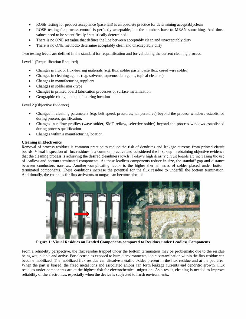
Cleaning in Electronics
Removal of process residues is common practice to reduce the risk of dendrites and leakage currents from printed circuit
boards. Visual inspection of flux residues is a common practice and considered the first step in obtaining objective evidence
that the cleaning process is achieving the desired cleanliness levels. Today’s high density circuit boards are increasing the use
of leadless and bottom terminated components. As these leadless components reduce in size, the standoff gap and distance
between conductors narrows. Another complicating factor is the higher thermal mass of solder placed under bottom
terminated components. These conditions increase the potential for the flux residue to underfill the bottom termination.
Additionally, the channels for flux activators to outgas can become blocked.
Figure 1: Visual Residues on Leaded Components compared to Residues under Leadless Components
From a reliability perspective, the flux residue trapped under the bottom termination may be problematic due to the residue
being wet, pliable and active. For electronics exposed to humid environments, ionic contamination within the flux residue can
become mobilized. The mobilized flux residue can dissolve metallic oxides present in the flux residue and at the pad area.
When the part is biased, the freed metal ions and associated anions can form leakage currents and dendritic growth. Flux
residues under components are at the highest risk for electrochemical migration. As a result, cleaning is needed to improve
reliability of the electronics, especially when the device is subjected to harsh environments.

Figure 2: Residues trapped under leadless components forming leakage currents and dendritic growth
Most cleaning processes are very effective at removing flux residues on the surface of the circuit board and next to leaded
devices. Visible residue is much easier to clean than residues under leadless components. One of the challenges that
assemblers face is the inspection process. Residues under leadless components are hard to visually see and inspect for.
Desoldering components can distort the residues present under the bottom termination. The heat applied to remove the
component can dissolve the flux residue and allow it to flow under the component.
Figure 3: Desoldering Components can cause flux residue to flow under the component termination
Component Shearing is a technique that can be used to destructively remove the component without distorting the residue
pattern. This technique is highly useful but requires a new test board for each condition evaluated. As a result, this technique
is done during process validation but used infrequently to monitor production processes.
Figure 4: Shearing component to inspect for residues and electrochemical migration
Research Purpose
The purpose of this research study is to develop a method to inspect for visible flux residues under leadless components. The
method is designed to address the requirement for visible residue as called out in Section 8 of J-STD-001. The standard
states:
Assemblies subjected to cleaning processes shall [N1P2D3] be free of visible residues which violate minimum electrical
clearance (MEC), unless the visible residues have been identified as benign through laboratory analysis or other means. All
other visible residue requirements shall [N1P2D3] be AABUS[2].
• Residues which DO NOT violate MEC are not a defect
• Residues which DO violate MEC are not a defect if one has objective evidence that the residue is not a
reliability risk
• All of this can be over-ridden with AABUS
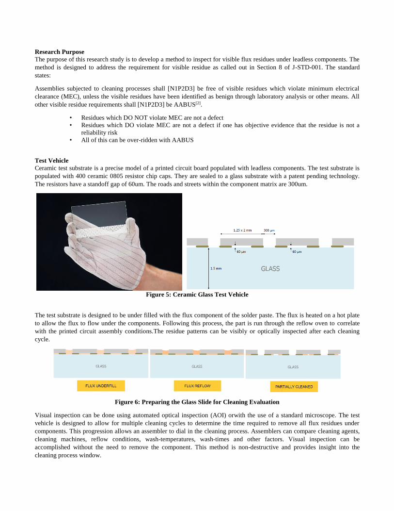
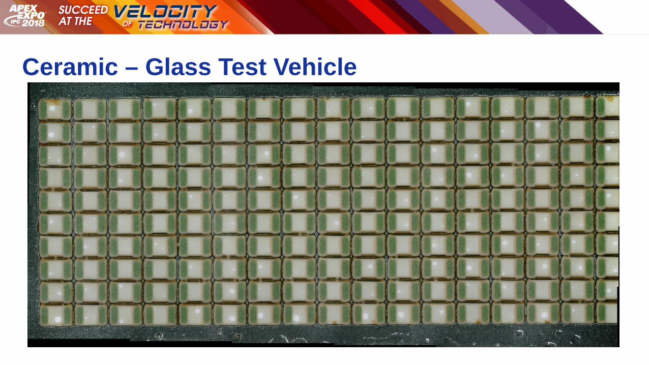
Test Vehicle
Ceramic test substrate is a precise model of a printed circuit board populated with leadless components. The test substrate is
populated with 400 ceramic 0805 resistor chip caps. They are sealed to a glass substrate with a patent pending technology.
The resistors have a standoff gap of 60um. The roads and streets within the component matrix are 300um.
Figure 5: Ceramic Glass Test Vehicle
The test substrate is designed to be under filled with the flux component of the solder paste. The flux is heated on a hot plate
to allow the flux to flow under the components. Following this process, the part is run through the reflow oven to correlate
with the printed circuit assembly conditions.The residue patterns can be visibly or optically inspected after each cleaning
cycle.
Figure 6: Preparing the Glass Slide for Cleaning Evaluation
Visual inspection can be done using automated optical inspection (AOI) orwith the use of a standard microscope. The test
vehicle is designed to allow for multiple cleaning cycles to determine the time required to remove all flux residues under
components. This progression allows an assembler to dial in the cleaning process. Assemblers can compare cleaning agents,
cleaning machines, reflow conditions, wash-temperatures, wash-times and other factors. Visual inspection can be
accomplished without the need to remove the component. This method is non-destructive and provides insight into the
cleaning process window.

Figure 7: After Reflow with Three Cleaning Cycles to Total Clean
Design of Experiment
The factors and levels researched are as follows:
1. Solder Paste
a. 5 – LF No-Clean
b. 1 – LF Water soluble
2. Batch Cleaning Machine
a. Spray-in-Air (Spray Against Surface using Linear Spray Arms)
b. Dishwasher Style using Linear Nozzle Arms
3. Nozzle Span
a. Spray-in-Air ~ 80 mm - 110mm(Distance Face- to Face of both nozzle orifices. Distance nozzle face to
PCBA face is about 55mm)
b. Dishwasher Style ~ Distance Face to Face of nozzles is 700mm - lower nozzle to substrate was 650mm -
lower nozzle to substrate center 180mm - upper nozzle to substrate center 740mm
4. Cleaning Agent
a. Engineered Aqueous
5. Wash Concentrate
a. 20% Wash Chemistry / 80% DI Water
6. Wash Cycles to Total Cleaning
a. 1 cycle
b. 2 cycles
c. 3 cycles
d. 4 cycles
e. 5 cycles
7. Wash Temperature °C
a. 50°C
8. Spray Bar Pressure
a. Spray-in-Air Linear ~ 2.9 Bar
b. Dishwasher Style using Linear Nozzle Arms 2,1 Bar
9. DI Rinse Cycles
a. Cycle #1 ~ 1.1 minutes
b. Cycle #2 ~ 2.2 minutes
10. Rinse Temperature
a. 40°C
11. Dry Time and Temperature
a. 10 minutes @ 110°C
Data Findings
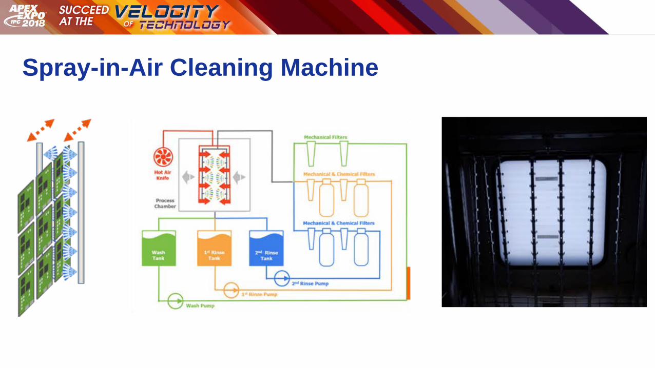
The first set of tests were performed in a batch cleaning machine designed with linear direct spray arms for equal washing
across the cleaning area. The linear spray arms track forward across the surface to the end of the cleaning area and then
reverse back across the cleaning area for a pre-set number of cycles. It takes roughly 30 seconds for the linear spray arm to
make one cycle before reversing direction. There are two linear arms, one for cleaning the front side of the printed circuit
board and one for cleaning the back side of the printed circuit board. The spray nozzles are placed sequentially within the
linear spray arms and are roughly 2 inches from the surface of the board being cleaned. The spray patterns are uniform across
the entire cleaning area, which prevents shadowing effects.
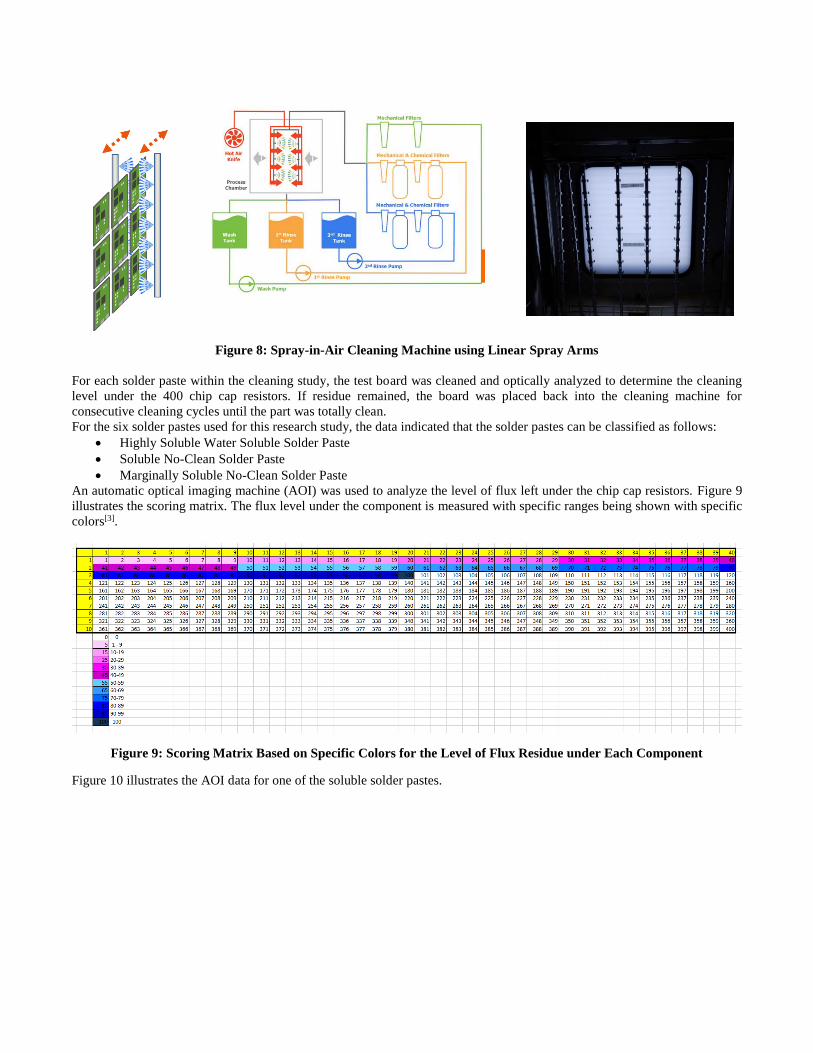
Figure 8: Spray-in-Air Cleaning Machine using Linear Spray Arms
For each solder paste within the cleaning study, the test board was cleaned and optically analyzed to determine the cleaning
level under the 400 chip cap resistors. If residue remained, the board was placed back into the cleaning machine for
consecutive cleaning cycles until the part was totally clean.
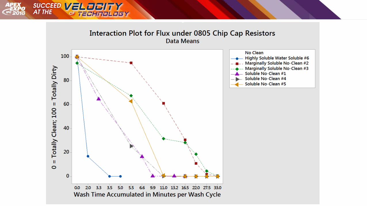
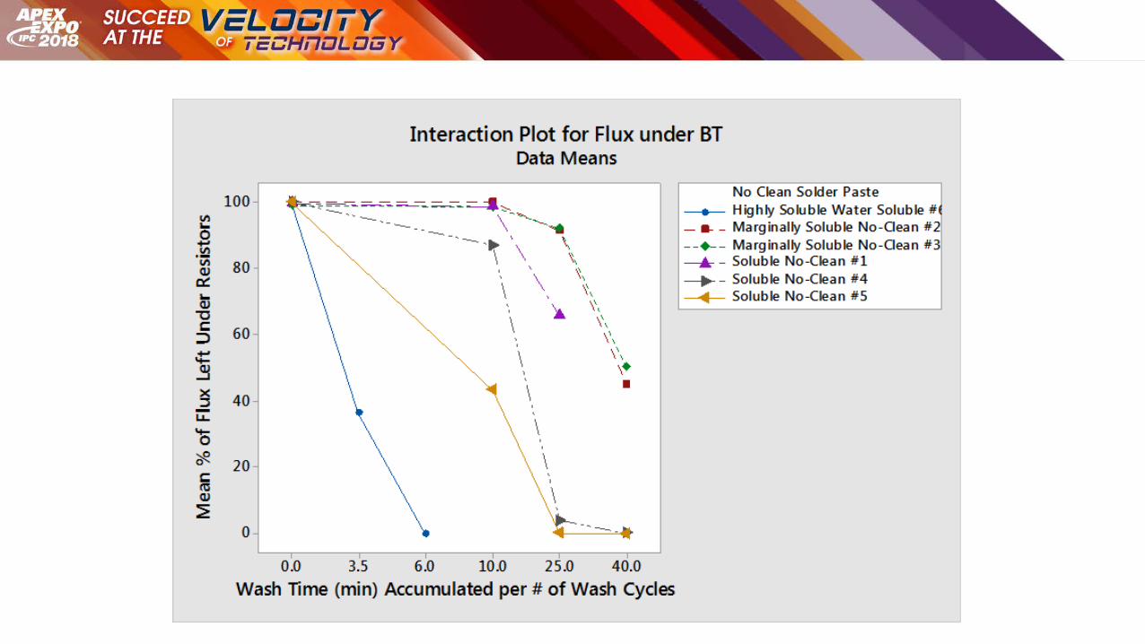
For the six solder pastes used for this research study, the data indicated that the solder pastes can be classified as follows:
• Highly Soluble Water Soluble Solder Paste
• Soluble No-Clean Solder Paste
• Marginally Soluble No-Clean Solder Paste
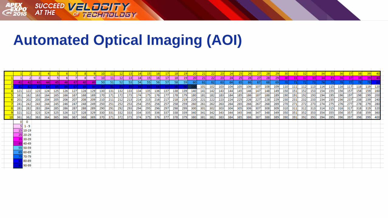
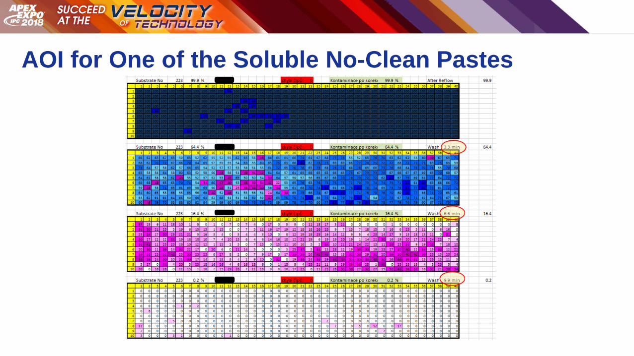
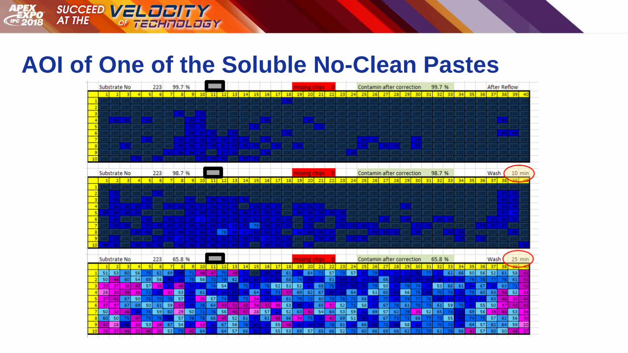
An automatic optical imaging machine (AOI) was used to analyze the level of flux left under the chip cap resistors. Figure 9
illustrates the scoring matrix. The flux level under the component is measured with specific ranges being shown with specific
colors[3].
Figure 9: Scoring Matrix Based on Specific Colors for the Level of Flux Residue under Each Component
Figure 10 illustrates the AOI data for one of the soluble solder pastes.

Figure 10: AOI scoring of one of the Soluble No-Clean Solder Pastes
The solubility of the solder paste in the cleaning agent dictated the number of cleaning cycles and the total amount of time
required to totally clean all flux residues under the 0805 chip cap resistors. It took roughly 3 times longer to clean a soluble
solder paste as compared to a highly soluble solder paste. When cleaning a marginally soluble solder paste, it took 10 times
longer to clean out a highly soluble solder paste and 3 times longer to clean versus a soluble solder paste. Figure 11
summarizes the data findings for the six solder pastes run in the spray-in-air cleaning machine using the linear spray arms.
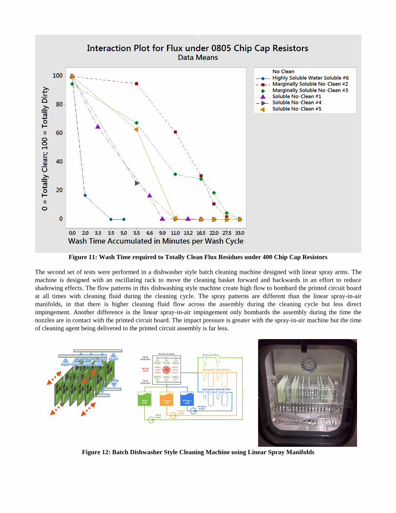
Figure 11: Wash Time required to Totally Clean Flux Residues under 400 Chip Cap Resistors
The second set of tests were performed in a dishwasher style batch cleaning machine designed with linear spray arms. The
machine is designed with an oscillating rack to move the cleaning basket forward and backwards in an effort to reduce
shadowing effects. The flow patterns in this dishwashing style machine create high flow to bombard the printed circuit board
at all times with cleaning fluid during the cleaning cycle. The spray patterns are different than the linear spray-in-air
manifolds, in that there is higher cleaning fluid flow across the assembly during the cleaning cycle but less direct
impingement. Another difference is the linear spray-in-air impingement only bombards the assembly during the time the
nozzles are in contact with the printed circuit board. The impact pressure is greater with the spray-in-air machine but the time
of cleaning agent being delivered to the printed circuit assembly is far less.
Figure 12: Batch Dishwasher Style Cleaning Machine using Linear Spray Manifolds
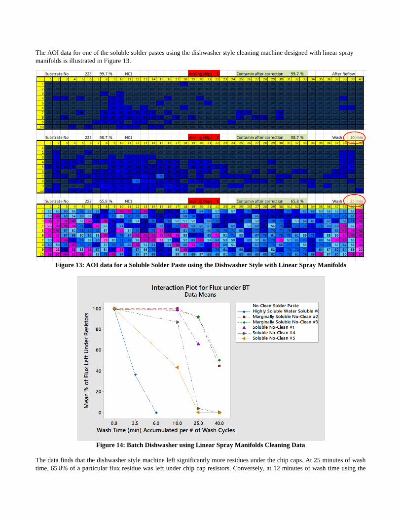
The AOI data for one of the soluble solder pastes using the dishwasher style cleaning machine designed with linear spray
manifolds is illustrated in Figure 13.
Figure 13: AOI data for a Soluble Solder Paste using the Dishwasher Style with Linear Spray Manifolds
Figure 14: Batch Dishwasher using Linear Spray Manifolds Cleaning Data
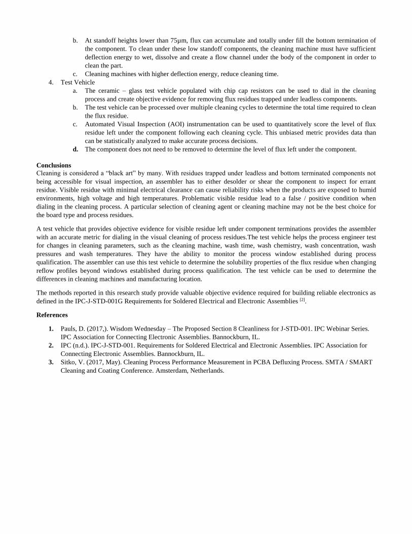
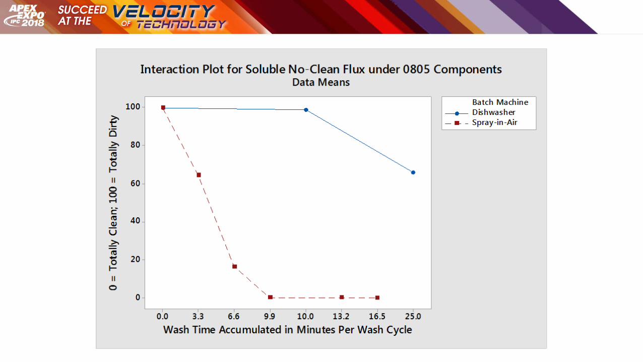
The data finds that the dishwasher style machine left significantly more residues under the chip caps. At 25 minutes of wash
time, 65.8% of a particular flux residue was left under chip cap resistors. Conversely, at 12 minutes of wash time using the
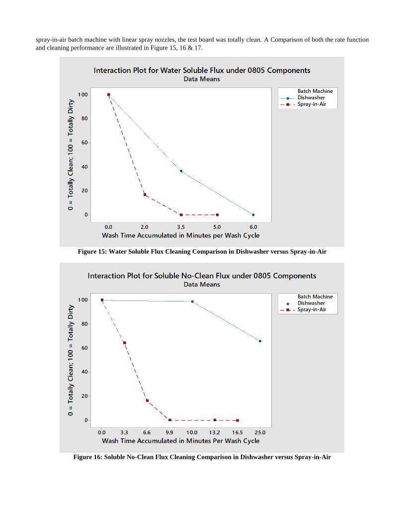
spray-in-air batch machine with linear spray nozzles, the test board was totally clean. A Comparison of both the rate function
and cleaning performance are illustrated in Figure 15, 16 & 17.
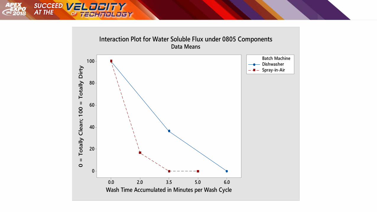
Figure 15: Water Soluble Flux Cleaning Comparison in Dishwasher versus Spray-in-Air
Figure 16: Soluble No-Clean Flux Cleaning Comparison in Dishwasher versus Spray-in-Air
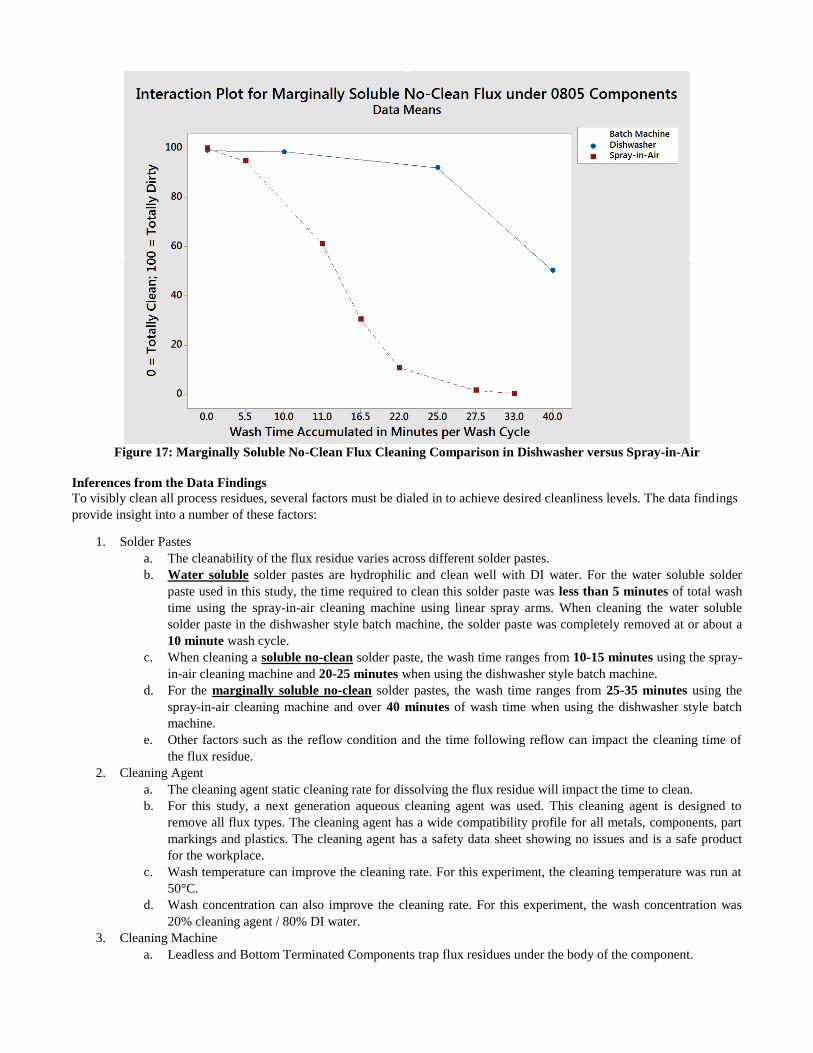
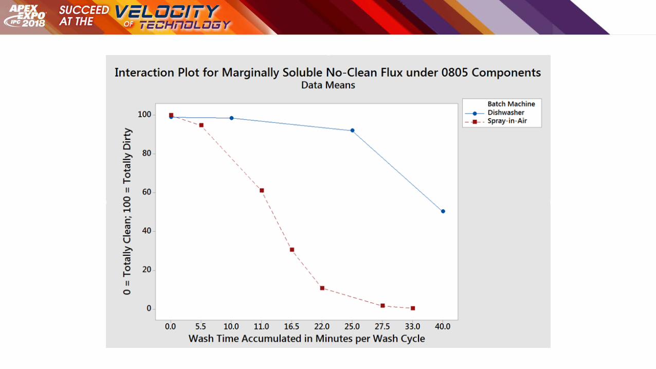
Figure 17: Marginally Soluble No-Clean Flux Cleaning Comparison in Dishwasher versus Spray-in-Air
Inferences from the Data Findings
To visibly clean all process residues, several factors must be dialed in to achieve desired cleanliness levels. The data findings
provide insight into a number of these factors:
1. Solder Pastes
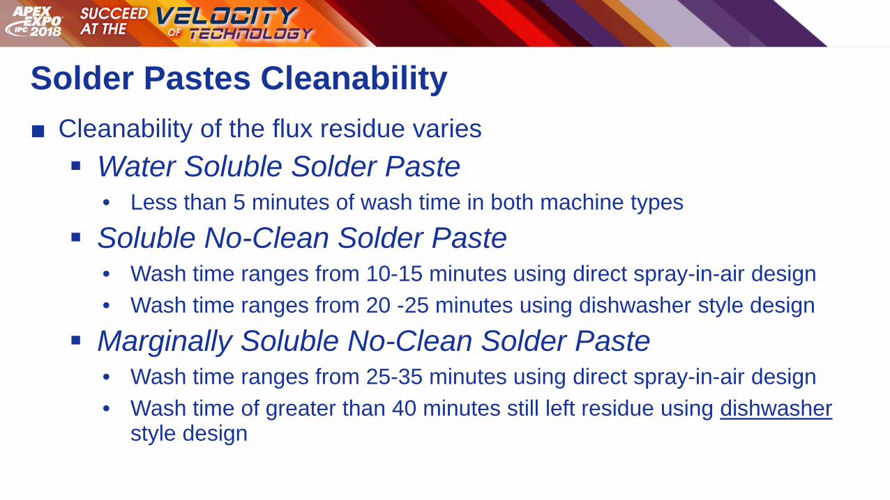
a. The cleanability of the flux residue varies across different solder pastes.
b. Water soluble solder pastes are hydrophilic and clean well with DI water. For the water soluble solder
paste used in this study, the time required to clean this solder paste was less than 5 minutes of total wash
time using the spray-in-air cleaning machine using linear spray arms. When cleaning the water soluble
solder paste in the dishwasher style batch machine, the solder paste was completely removed at or about a
10 minute wash cycle.
c. When cleaning a soluble no-clean solder paste, the wash time ranges from 10-15 minutes using the spray-
in-air cleaning machine and 20-25 minutes when using the dishwasher style batch machine.
d. For the marginally soluble no-clean solder pastes, the wash time ranges from 25-35 minutes using the
spray-in-air cleaning machine and over 40 minutes of wash time when using the dishwasher style batch
machine.
e. Other factors such as the reflow condition and the time following reflow can impact the cleaning time of
the flux residue.
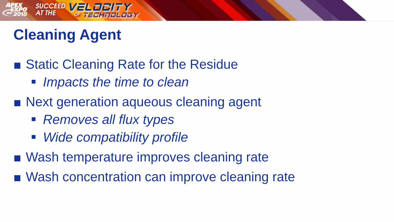
2. Cleaning Agent
a. The cleaning agent static cleaning rate for dissolving the flux residue will impact the time to clean.
b. For this study, a next generation aqueous cleaning agent was used. This cleaning agent is designed to
remove all flux types. The cleaning agent has a wide compatibility profile for all metals, components, part
markings and plastics. The cleaning agent has a safety data sheet showing no issues and is a safe product
for the workplace.
c. Wash temperature can improve the cleaning rate. For this experiment, the cleaning temperature was run at
50°C.
d. Wash concentration can also improve the cleaning rate. For this experiment, the wash concentration was
20% cleaning agent / 80% DI water.
3. Cleaning Machine
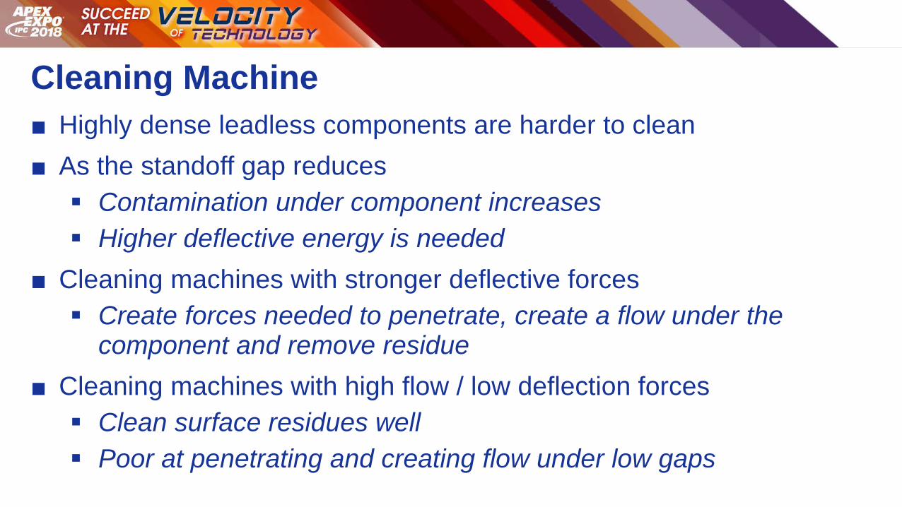
a. Leadless and Bottom Terminated Components trap flux residues under the body of the component.
b. At standoff heights lower than 75µm, flux can accumulate and totally under fill the bottom termination of
the component. To clean under these low standoff components, the cleaning machine must have sufficient
deflection energy to wet, dissolve and create a flow channel under the body of the component in order to
clean the part.
c. Cleaning machines with higher deflection energy, reduce cleaning time.
4. Test Vehicle
a. The ceramic – glass test vehicle populated with chip cap resistors can be used to dial in the cleaning
process and create objective evidence for removing flux residues trapped under leadless components.
b. The test vehicle can be processed over multiple cleaning cycles to determine the total time required to clean
the flux residue.
c. Automated Visual Inspection (AOI) instrumentation can be used to quantitatively score the level of flux
residue left under the component following each cleaning cycle. This unbiased metric provides data than
can be statistically analyzed to make accurate process decisions.
d. The component does not need to be removed to determine the level of flux left under the component.
Conclusions
Cleaning is considered a “black art” by many. With residues trapped under leadless and bottom terminated components not
being accessible for visual inspection, an assembler has to either desolder or shear the component to inspect for errant
residue. Visible residue with minimal electrical clearance can cause reliability risks when the products are exposed to humid
environments, high voltage and high temperatures. Problematic visible residue lead to a false / positive condition when
dialing in the cleaning process. A particular selection of cleaning agent or cleaning machine may not be the best choice for
the board type and process residues.
A test vehicle that provides objective evidence for visible residue left under component terminations provides the assembler
with an accurate metric for dialing in the visual cleaning of process residues.The test vehicle helps the process engineer test
for changes in cleaning parameters, such as the cleaning machine, wash time, wash chemistry, wash concentration, wash
pressures and wash temperatures. They have the ability to monitor the process window established during process
qualification. The assembler can use this test vehicle to determine the solubility properties of the flux residue when changing
reflow profiles beyond windows established during process qualification. The test vehicle can be used to determine the
differences in cleaning machines and manufacturing location.
The methods reported in this research study provide valuable objective evidence required for building reliable electronics as
defined in the IPC-J-STD-001G Requirements for Soldered Electrical and Electronic Assemblies [2].
References
1. Pauls, D. (2017,). Wisdom Wednesday – The Proposed Section 8 Cleanliness for J-STD-001. IPC Webinar Series.
IPC Association for Connecting Electronic Assemblies. Bannockburn, IL.
2. IPC (n.d.). IPC-J-STD-001. Requirements for Soldered Electrical and Electronic Assemblies. IPC Association for
Connecting Electronic Assemblies. Bannockburn, IL.
3. Sitko, V. (2017, May). Cleaning Process Performance Measurement in PCBA Defluxing Process. SMTA / SMART
Cleaning and Coating Conference. Amsterdam, Netherlands.
Cleaning Flux Residue Under Leadless Components
Using Objective Evidence To
Determine Cleaning Performance
Mike Bixenman, Kyzen Corporation
Vladimir Sitko, PBT-Works
Paper Outline
I. Introduction
II. Cleaning in Electronics
III. Research Purpose
IV. Test Vehicle
V. Experimental Design
VI. Data Findings
VII. Inferences from the Data Findings
VIII.Conclusions

Introduction
Cleanliness Testing
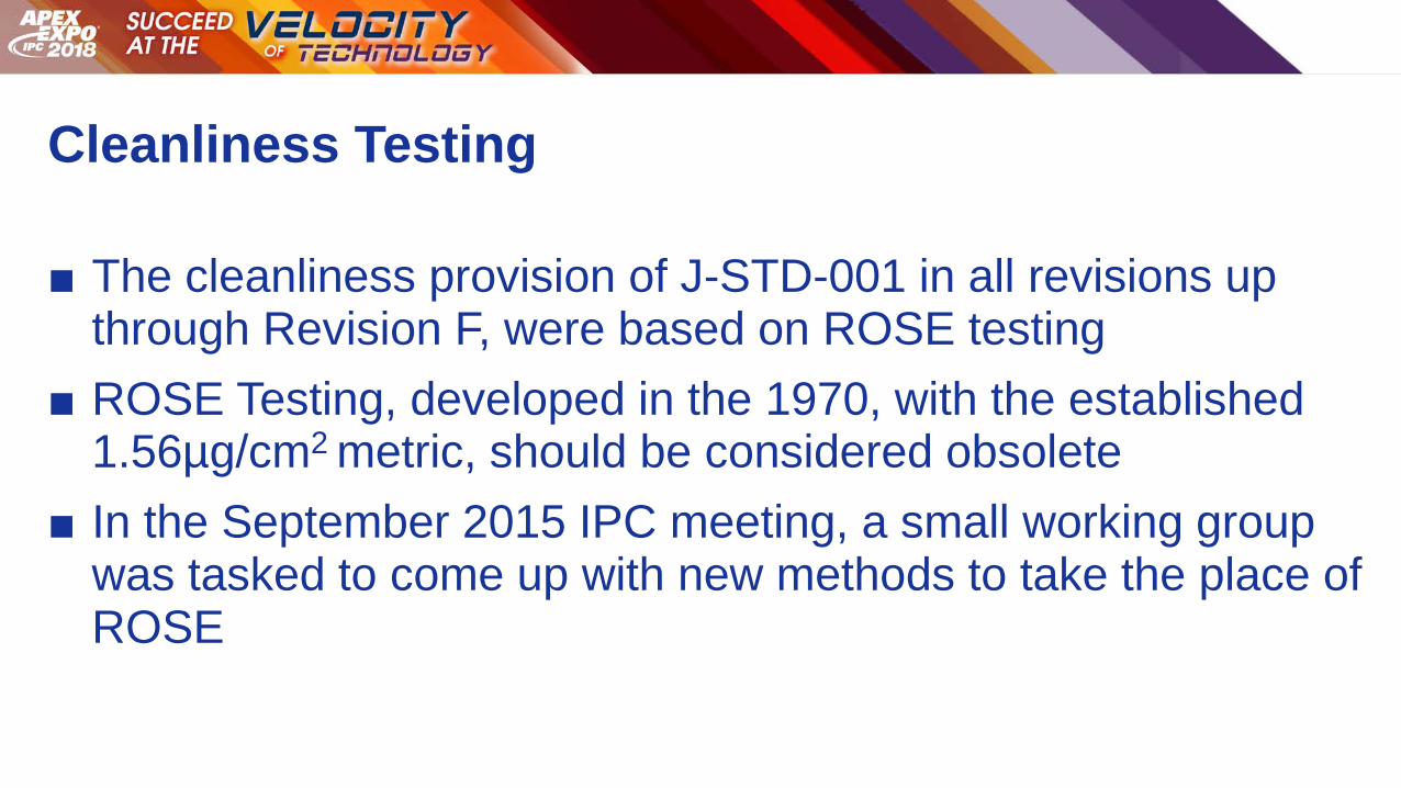
■ The cleanliness provision of J-STD-001 in all revisions up through Revision F, were based on ROSE testing
■ ROSE Testing, developed in the 1970, with the established 1.56µg/cm2 metric, should be considered obsolete
■ In the September 2015 IPC meeting, a small working group was tasked to come up with new methods to take the place of ROSE
Qualified Manufacturing Process
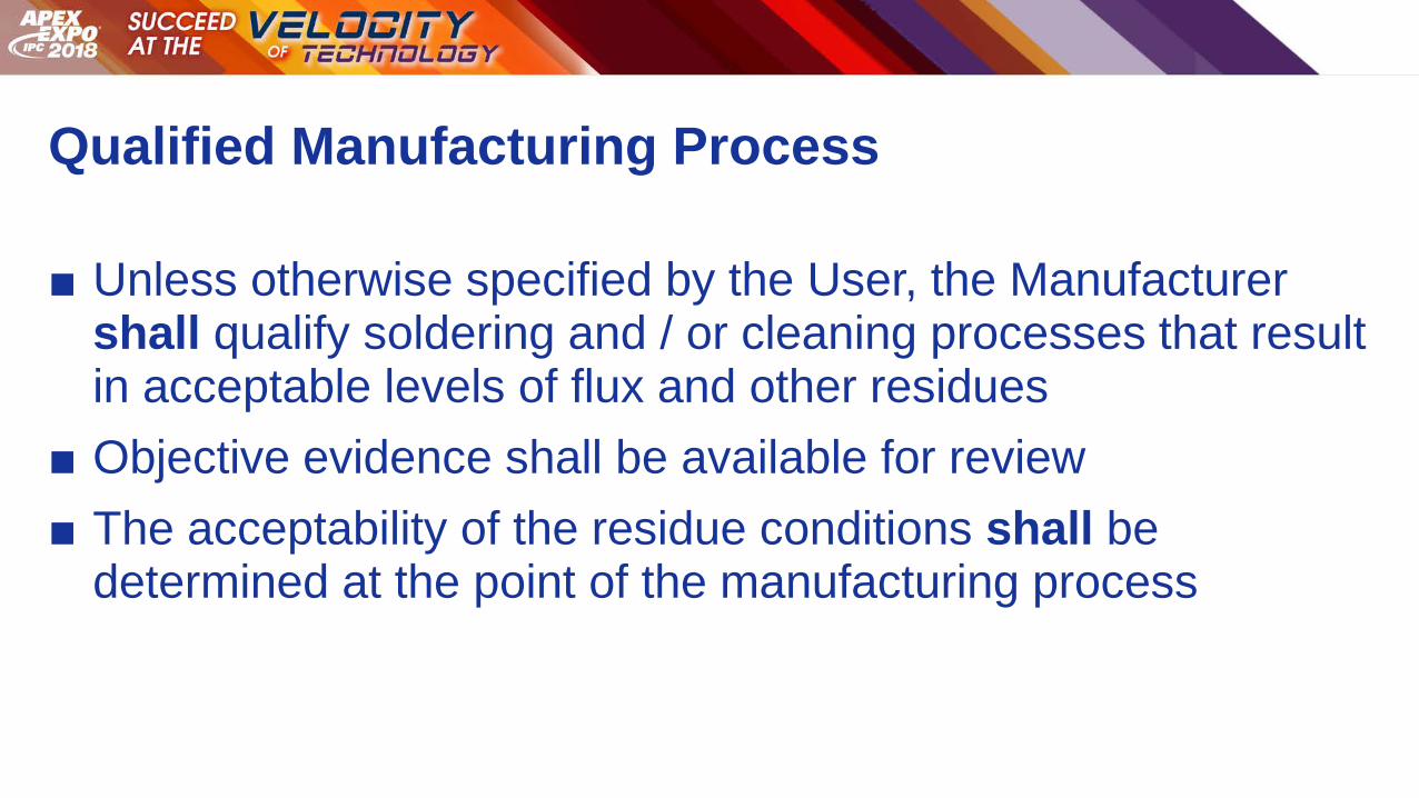
■ Unless otherwise specified by the User, the Manufacturer shall qualify soldering and / or cleaning processes that result in acceptable levels of flux and other residues
■ Objective evidence shall be available for review
■ The acceptability of the residue conditions shall be determined at the point of the manufacturing process
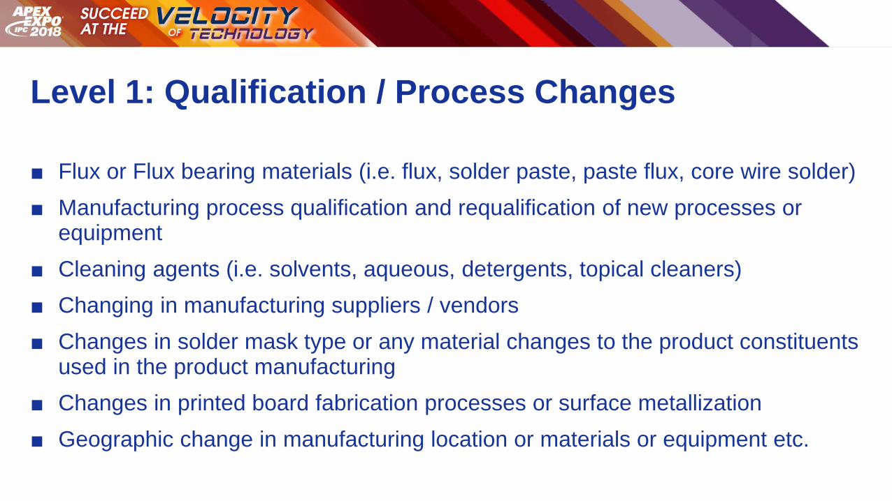
Level 1: Qualification / Process Changes
■ Flux or Flux bearing materials (i.e. flux, solder paste, paste flux, core wire solder)
■ Manufacturing process qualification and requalification of new processes or equipment
■ Cleaning agents (i.e. solvents, aqueous, detergents, topical cleaners)
■ Changing in manufacturing suppliers / vendors
■ Changes in solder mask type or any material changes to the product constituents used in the product manufacturing
■ Changes in printed board fabrication processes or surface metallization
■ Geographic change in manufacturing location or materials or equipment etc.

Level 2: Validation by Objective Evidence
■ Changes in cleaning parameters (i.e. belt speed, pressures, temperature) beyond the process windows established during process qualification
■ Changes in reflow profiles (wave solder, SMT reflow, selective solder) beyond process windows established during process qualification
■ Changes within a manufacturing location
■ Changes in any material sets or components
■ Changes of equipment or auxiliary processing equipment or processes

Cleaning in Electronics
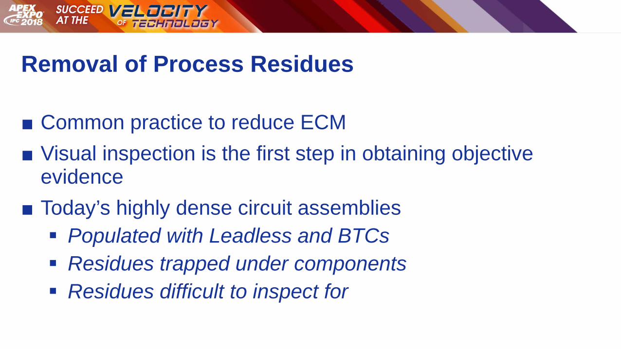
Removal of Process Residues
■ Common practice to reduce ECM
■ Visual inspection is the first step in obtaining objective evidence
■ Today’s highly dense circuit assemblies
Populated with Leadless and BTCs Residues trapped under components Residues difficult to inspect for

Leaded versus Leadless Components
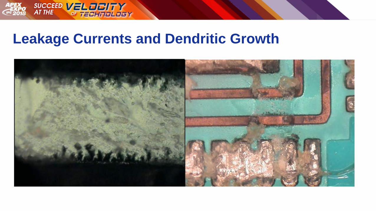
Leakage Currents and Dendritic Growth
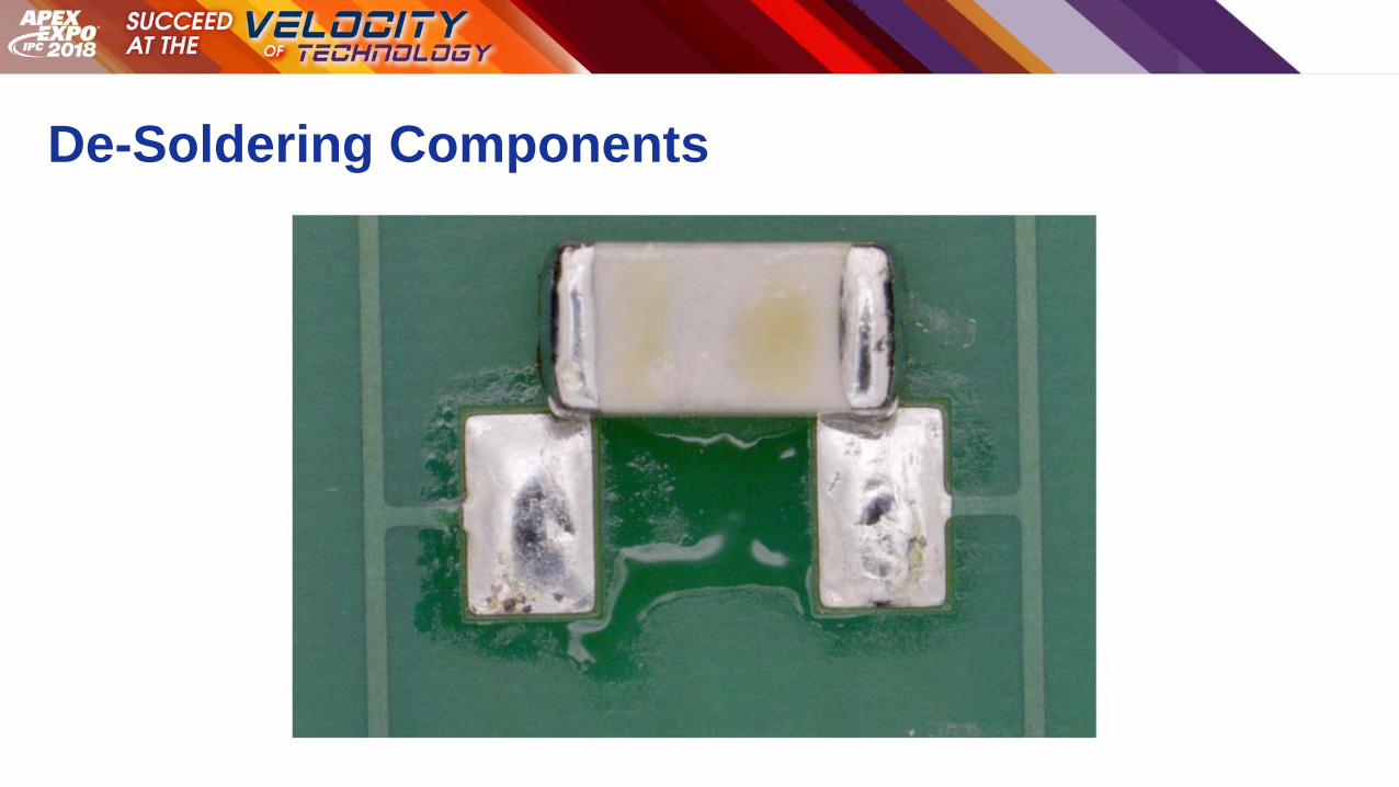
De-Soldering Components
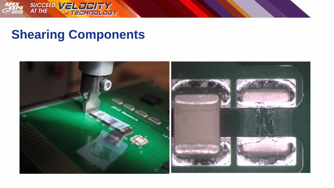
Shearing Components

Research Purpose
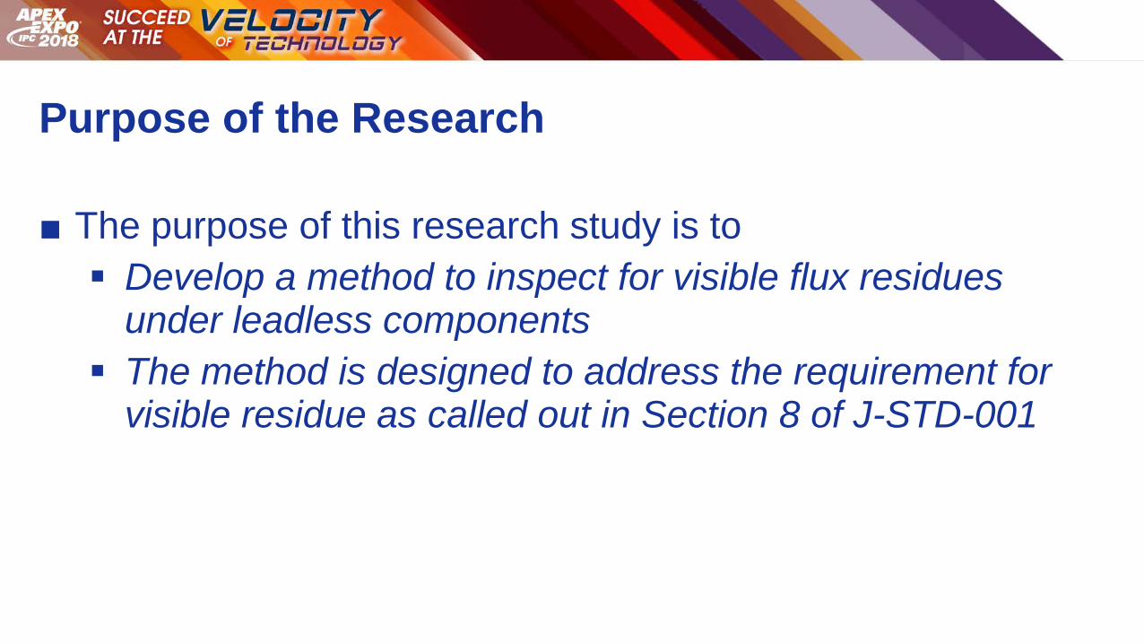
Purpose of the Research
■ The purpose of this research study is to
Develop a method to inspect for visible flux residues under leadless components
The method is designed to address the requirement for visible residue as called out in Section 8 of J-STD-001
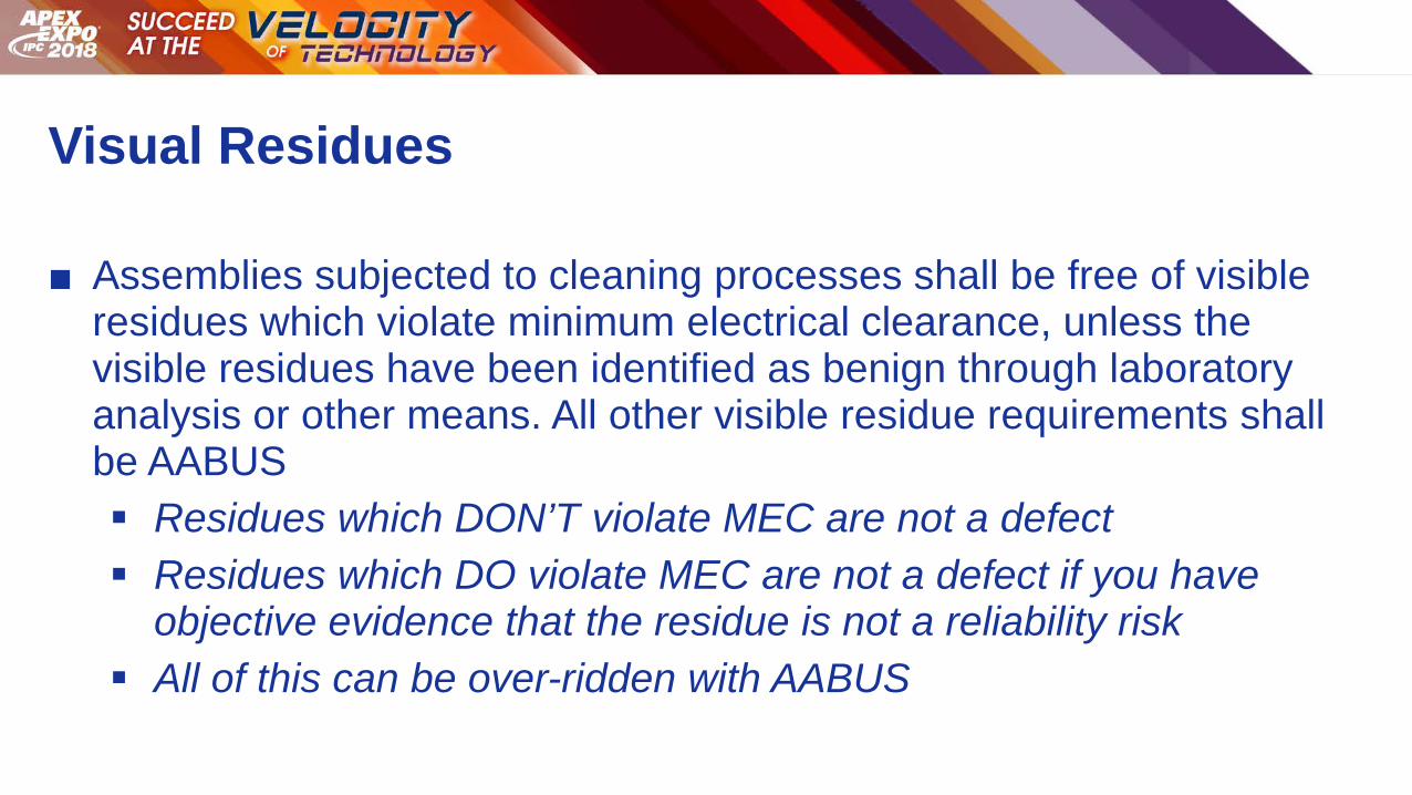
Visual Residues
■ Assemblies subjected to cleaning processes shall be free of visible residues which violate minimum electrical clearance, unless the visible residues have been identified as benign through laboratory analysis or other means. All other visible residue requirements shall be AABUS
Residues which DON’T violate MEC are not a defect Residues which DO violate MEC are not a defect if you have
objective evidence that the residue is not a reliability risk All of this can be over-ridden with AABUS

Test Vehicle
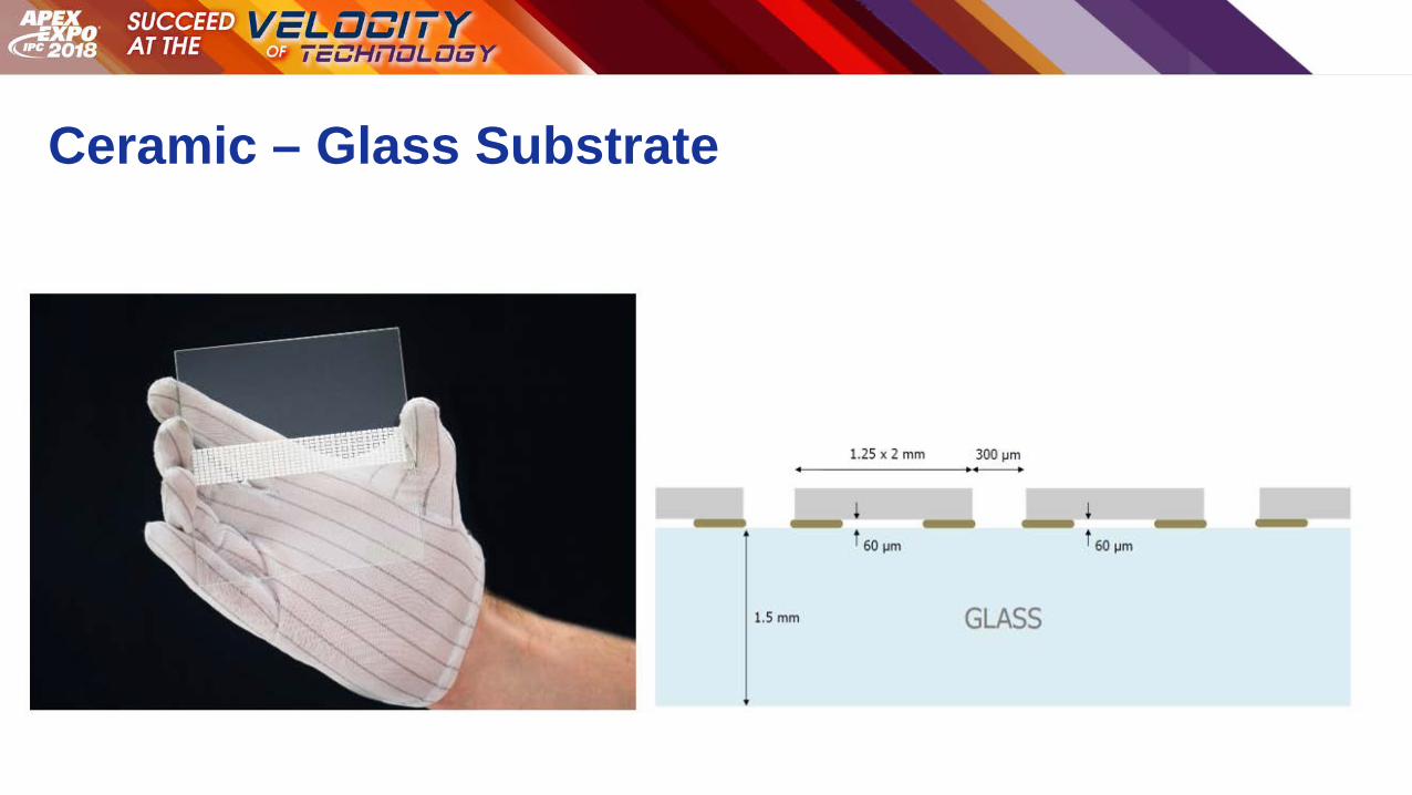
Ceramic – Glass Substrate

Solder Paste Flux Cleanliness Evaluations

Experimental Design
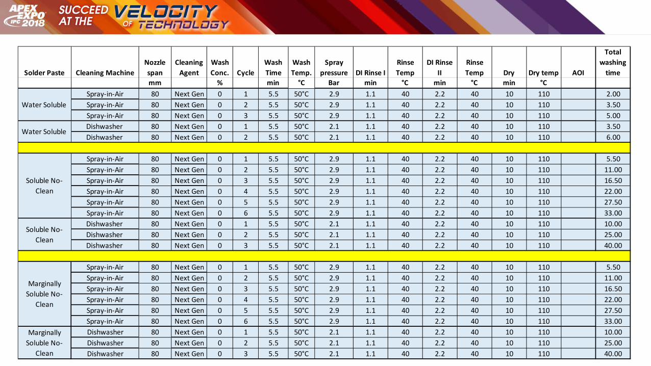
Solder Paste Cleaning MachineNozzle span
Cleaning Agent
Wash Conc. Cycle
Wash Time
Wash Temp.
Spray pressure DI Rinse I
Rinse Temp
DI Rinse II
Rinse Temp Dry Dry temp AOI
Total washing
timemm % min °C Bar min °C min °C min °C
Spray-in-Air 80 Next Gen 0 1 5.5 50°C 2.9 1.1 40 2.2 40 10 110 2.00Spray-in-Air 80 Next Gen 0 2 5.5 50°C 2.9 1.1 40 2.2 40 10 110 3.50Spray-in-Air 80 Next Gen 0 3 5.5 50°C 2.9 1.1 40 2.2 40 10 110 5.00Dishwasher 80 Next Gen 0 1 5.5 50°C 2.1 1.1 40 2.2 40 10 110 3.50Dishwasher 80 Next Gen 0 2 5.5 50°C 2.1 1.1 40 2.2 40 10 110 6.00
Spray-in-Air 80 Next Gen 0 1 5.5 50°C 2.9 1.1 40 2.2 40 10 110 5.50Spray-in-Air 80 Next Gen 0 2 5.5 50°C 2.9 1.1 40 2.2 40 10 110 11.00Spray-in-Air 80 Next Gen 0 3 5.5 50°C 2.9 1.1 40 2.2 40 10 110 16.50Spray-in-Air 80 Next Gen 0 4 5.5 50°C 2.9 1.1 40 2.2 40 10 110 22.00Spray-in-Air 80 Next Gen 0 5 5.5 50°C 2.9 1.1 40 2.2 40 10 110 27.50Spray-in-Air 80 Next Gen 0 6 5.5 50°C 2.9 1.1 40 2.2 40 10 110 33.00Dishwasher 80 Next Gen 0 1 5.5 50°C 2.1 1.1 40 2.2 40 10 110 10.00Dishwasher 80 Next Gen 0 2 5.5 50°C 2.1 1.1 40 2.2 40 10 110 25.00Dishwasher 80 Next Gen 0 3 5.5 50°C 2.1 1.1 40 2.2 40 10 110 40.00
Spray-in-Air 80 Next Gen 0 1 5.5 50°C 2.9 1.1 40 2.2 40 10 110 5.50Spray-in-Air 80 Next Gen 0 2 5.5 50°C 2.9 1.1 40 2.2 40 10 110 11.00Spray-in-Air 80 Next Gen 0 3 5.5 50°C 2.9 1.1 40 2.2 40 10 110 16.50Spray-in-Air 80 Next Gen 0 4 5.5 50°C 2.9 1.1 40 2.2 40 10 110 22.00Spray-in-Air 80 Next Gen 0 5 5.5 50°C 2.9 1.1 40 2.2 40 10 110 27.50Spray-in-Air 80 Next Gen 0 6 5.5 50°C 2.9 1.1 40 2.2 40 10 110 33.00Dishwasher 80 Next Gen 0 1 5.5 50°C 2.1 1.1 40 2.2 40 10 110 10.00Dishwasher 80 Next Gen 0 2 5.5 50°C 2.1 1.1 40 2.2 40 10 110 25.00Dishwasher 80 Next Gen 0 3 5.5 50°C 2.1 1.1 40 2.2 40 10 110 40.00
Water Soluble
Water Soluble
Soluble No-Clean
Soluble No-Clean
Marginally Soluble No-
Clean
Marginally Soluble No-
Clean
Automated Optical Imaging (AOI)
Spray-in-Air Data Findings
Spray-in-Air Cleaning Machine
AOI for One of the Soluble No-Clean Pastes
Ceramic – Glass Test Vehicle
Water Soluble After Reflow
0
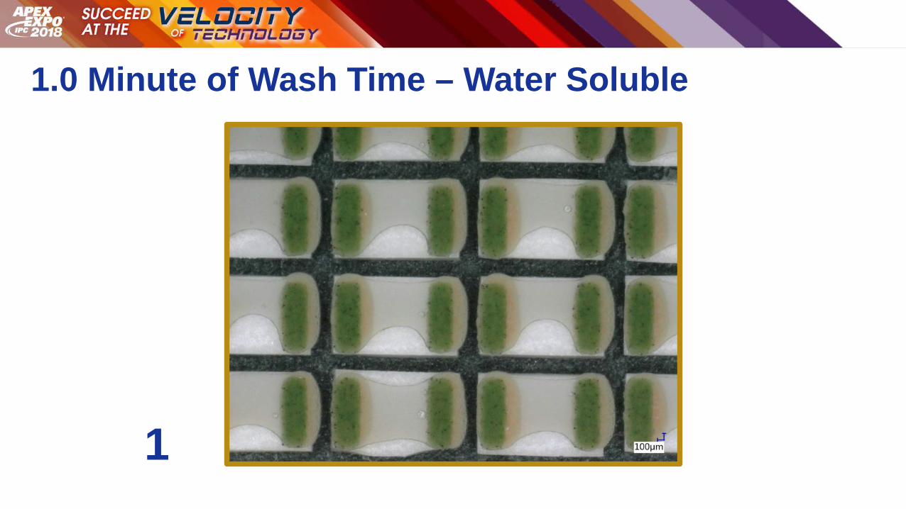
1.0 Minute of Wash Time – Water Soluble
1
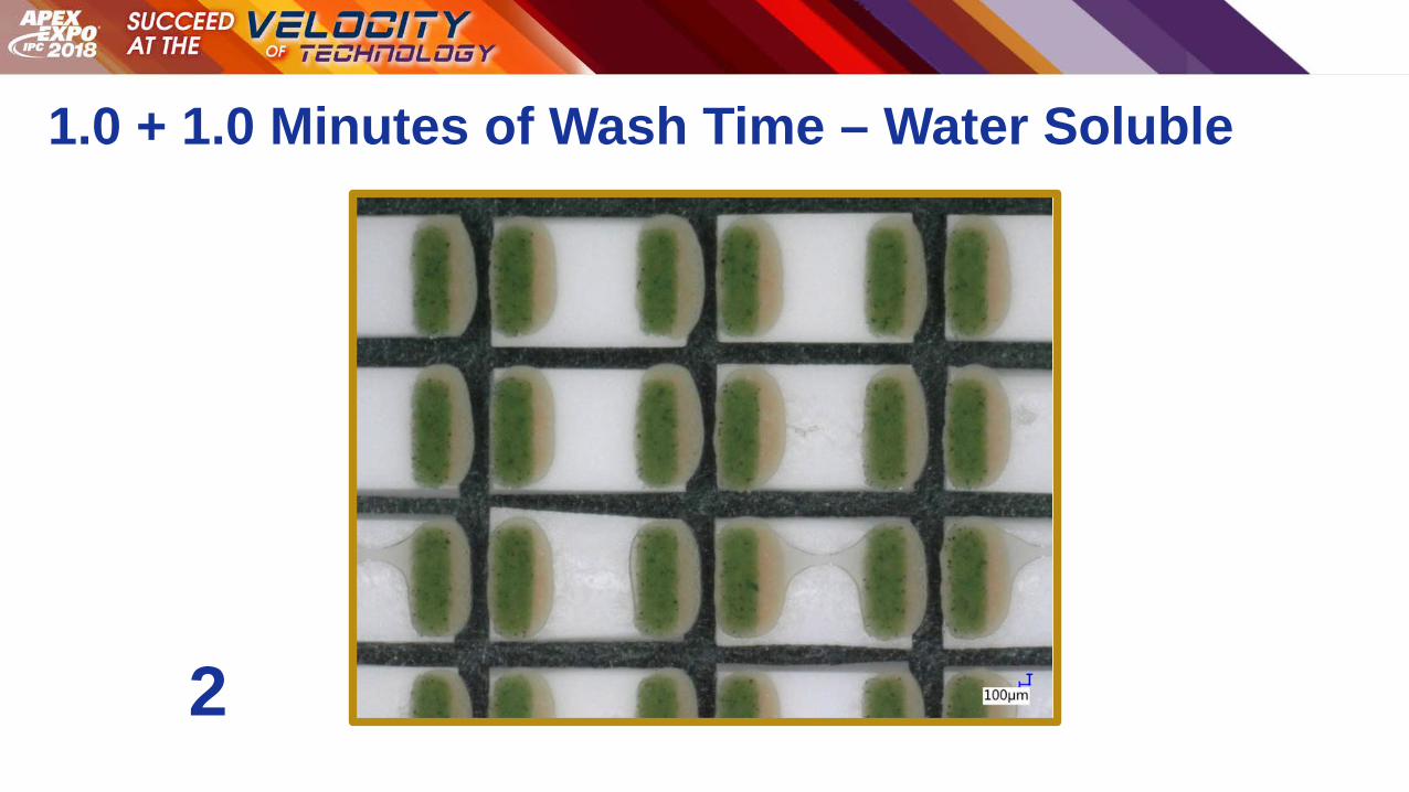
1.0 + 1.0 Minutes of Wash Time – Water Soluble
2
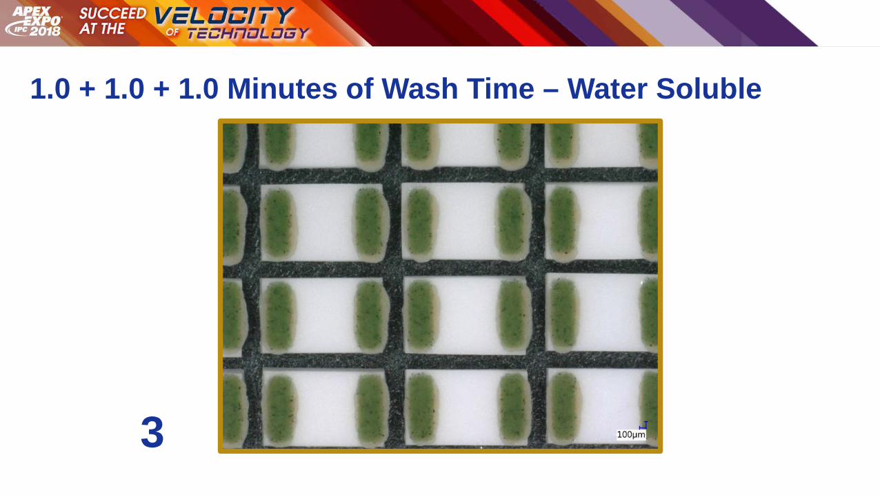
1.0 + 1.0 + 1.0 Minutes of Wash Time – Water Soluble
3
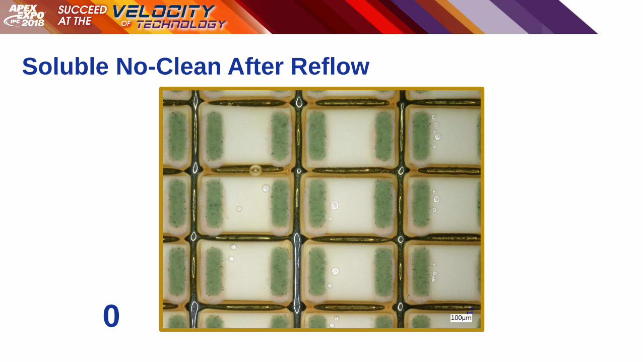
Soluble No-Clean After Reflow
0
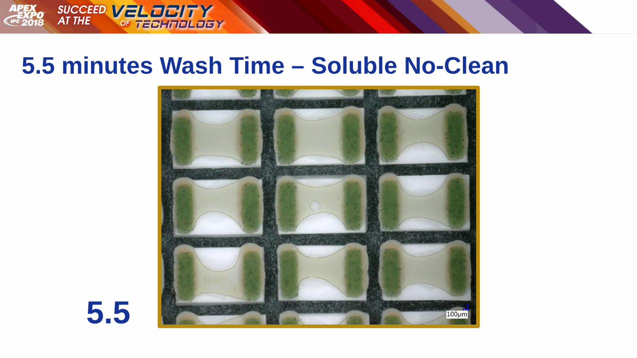
5.5 minutes Wash Time – Soluble No-Clean
5.5
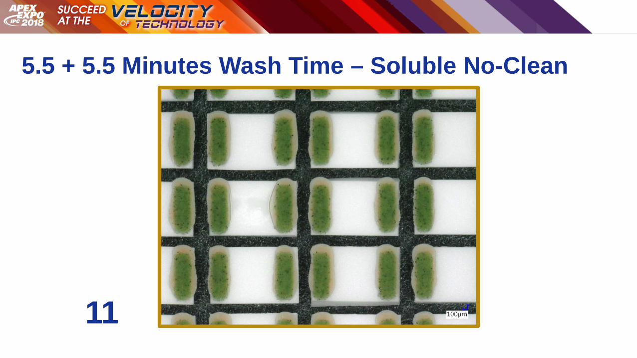
5.5 + 5.5 Minutes Wash Time – Soluble No-Clean
11
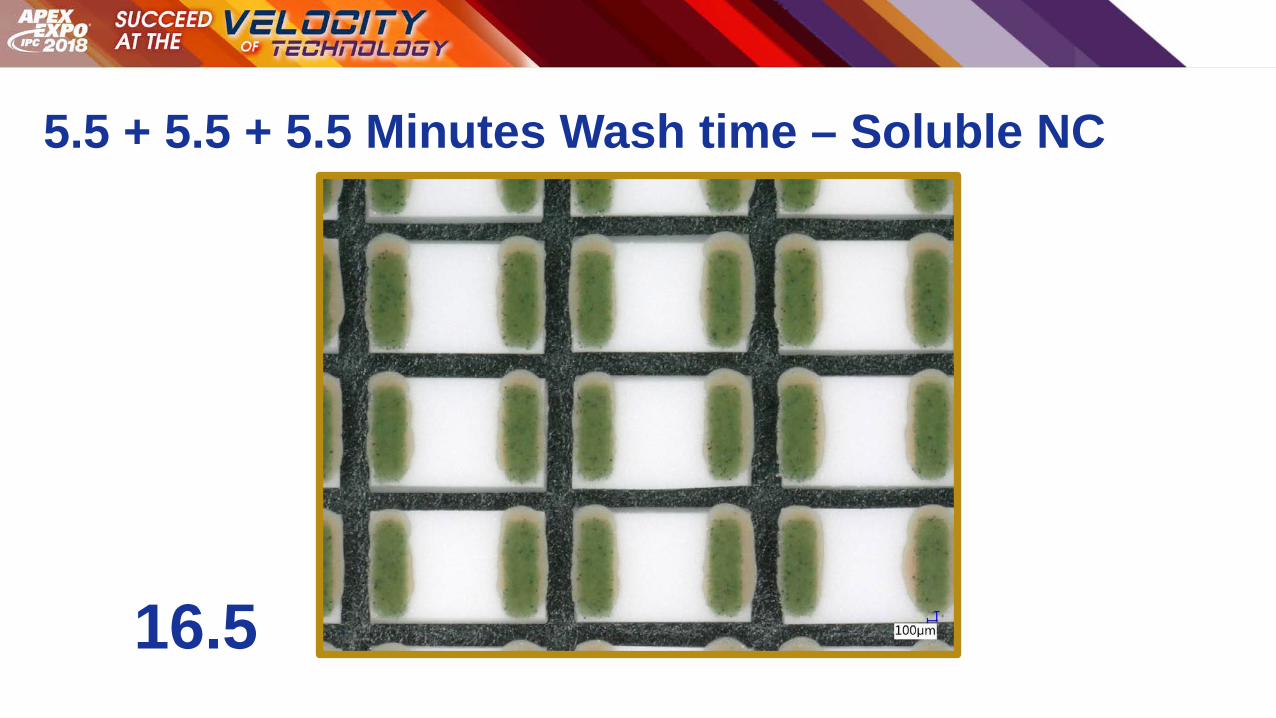
5.5 + 5.5 + 5.5 Minutes Wash time – Soluble NC
16.5
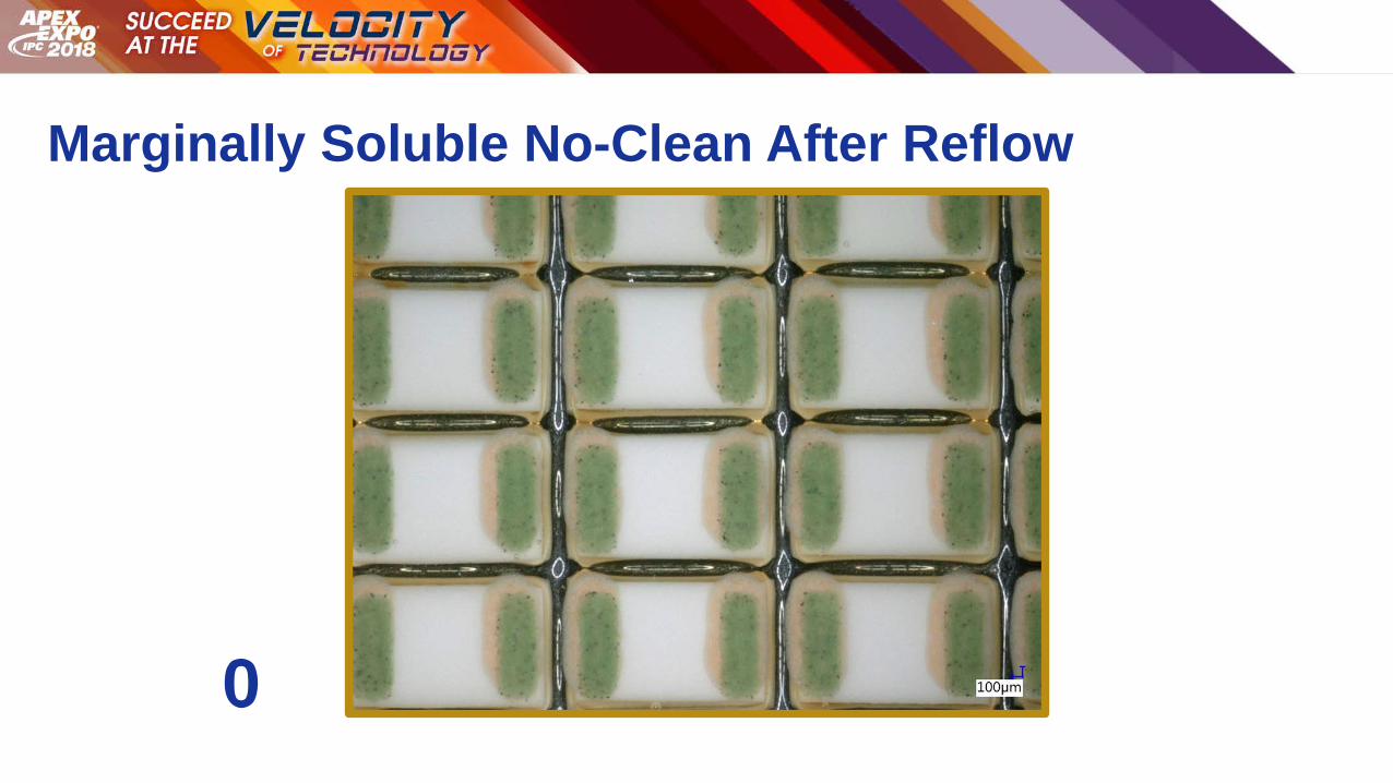
Marginally Soluble No-Clean After Reflow
0
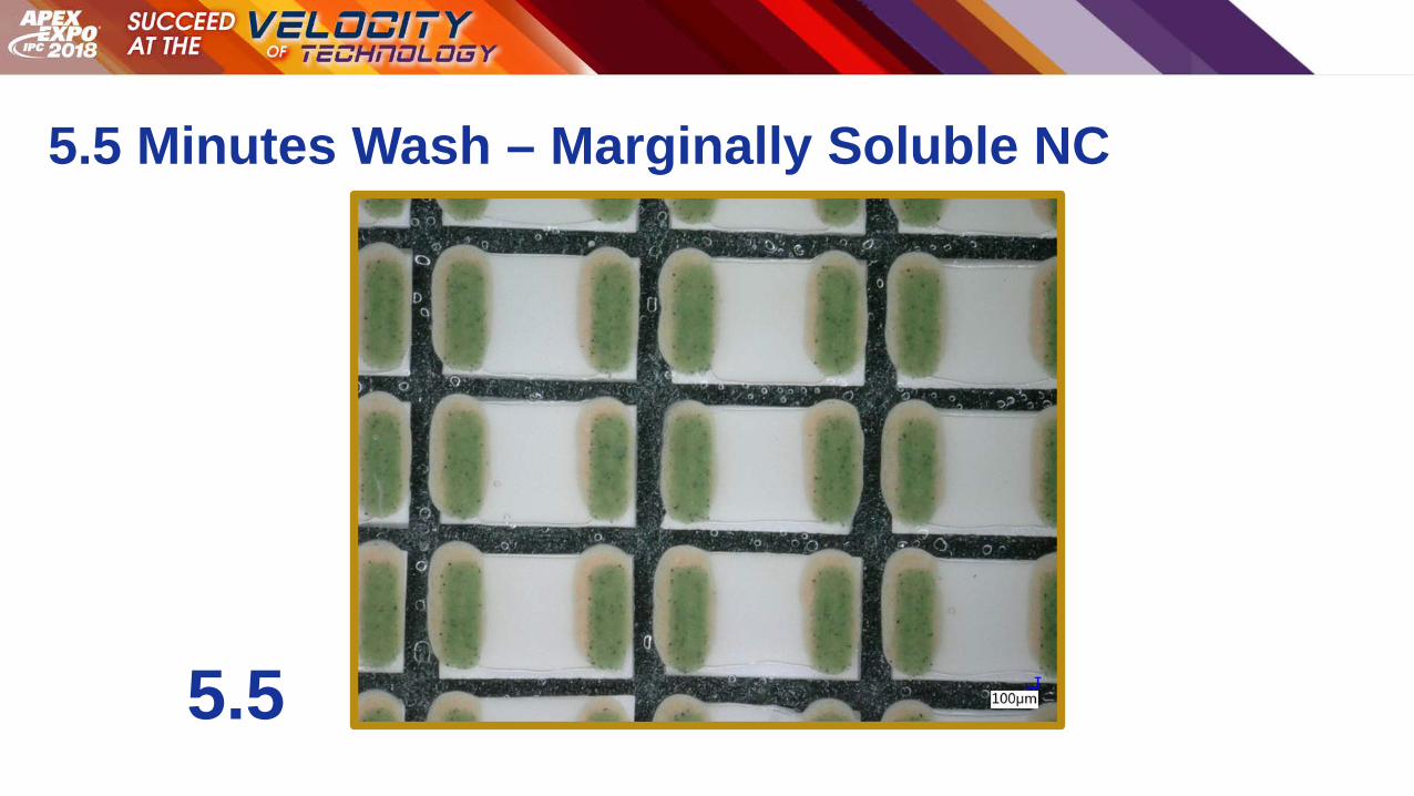
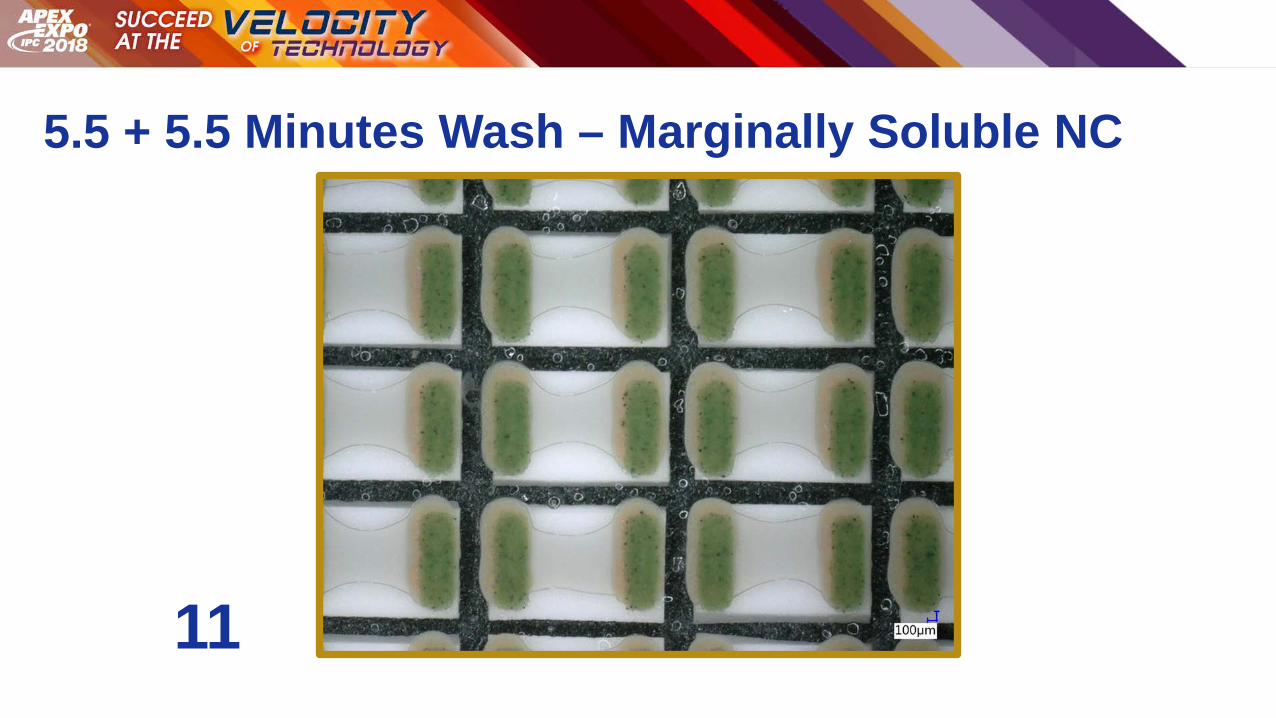
5.5 Minutes Wash – Marginally Soluble NC
5.5
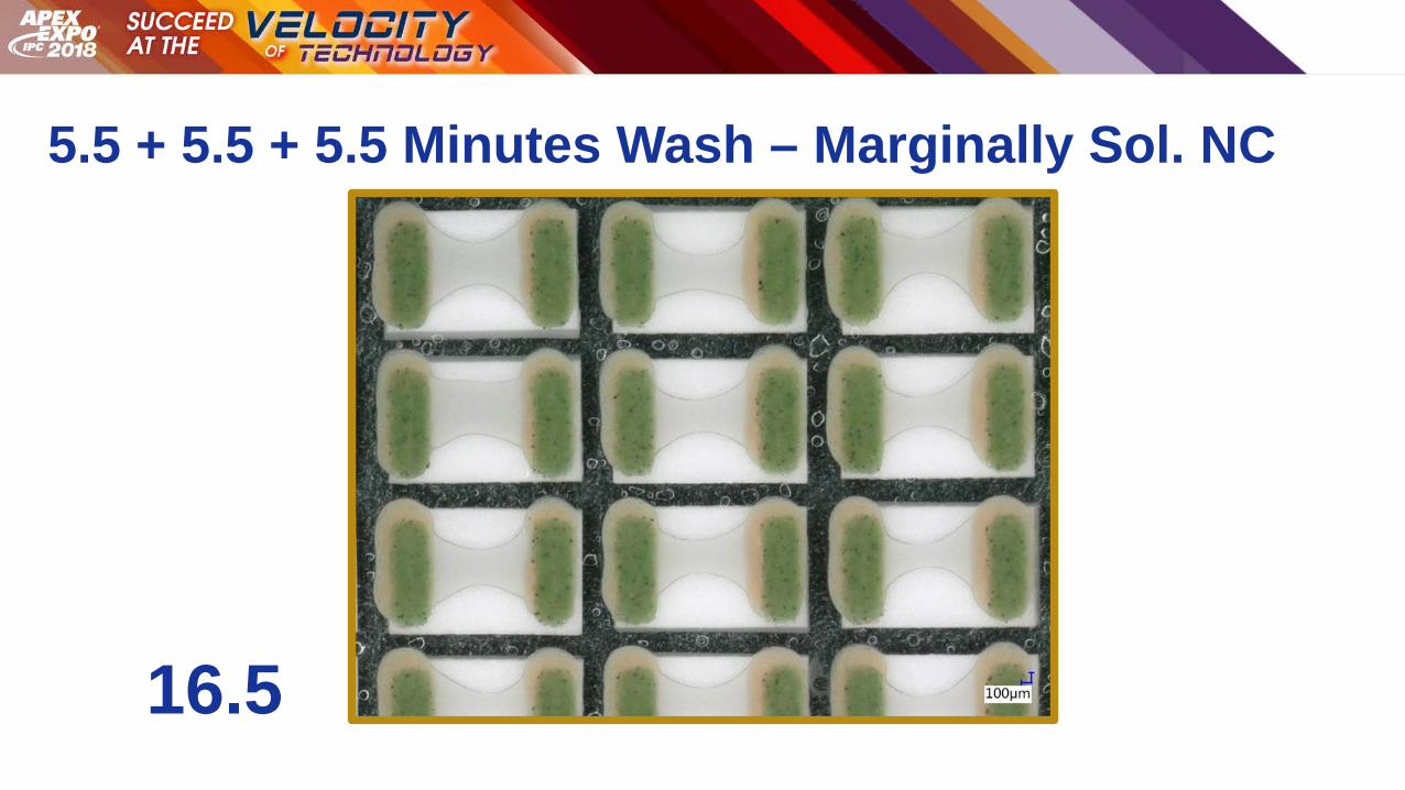
5.5 + 5.5 Minutes Wash – Marginally Soluble NC
11
5.5 + 5.5 + 5.5 Minutes Wash – Marginally Sol. NC
16.5
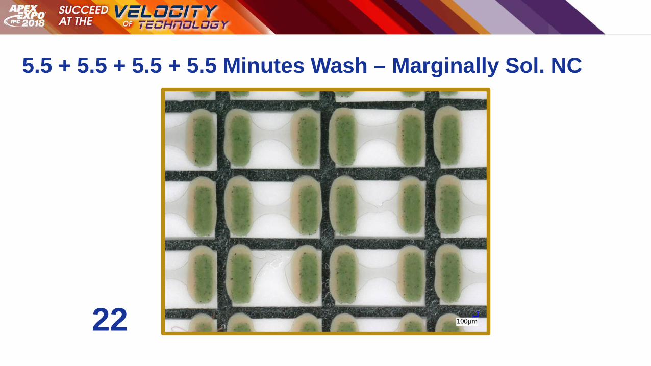
5.5 + 5.5 + 5.5 + 5.5 Minutes Wash – Marginally Sol. NC
22

5.5 + 5.5 + 5.5 + 5.5 + 5.5 Minutes Wash – MS NC
27.5
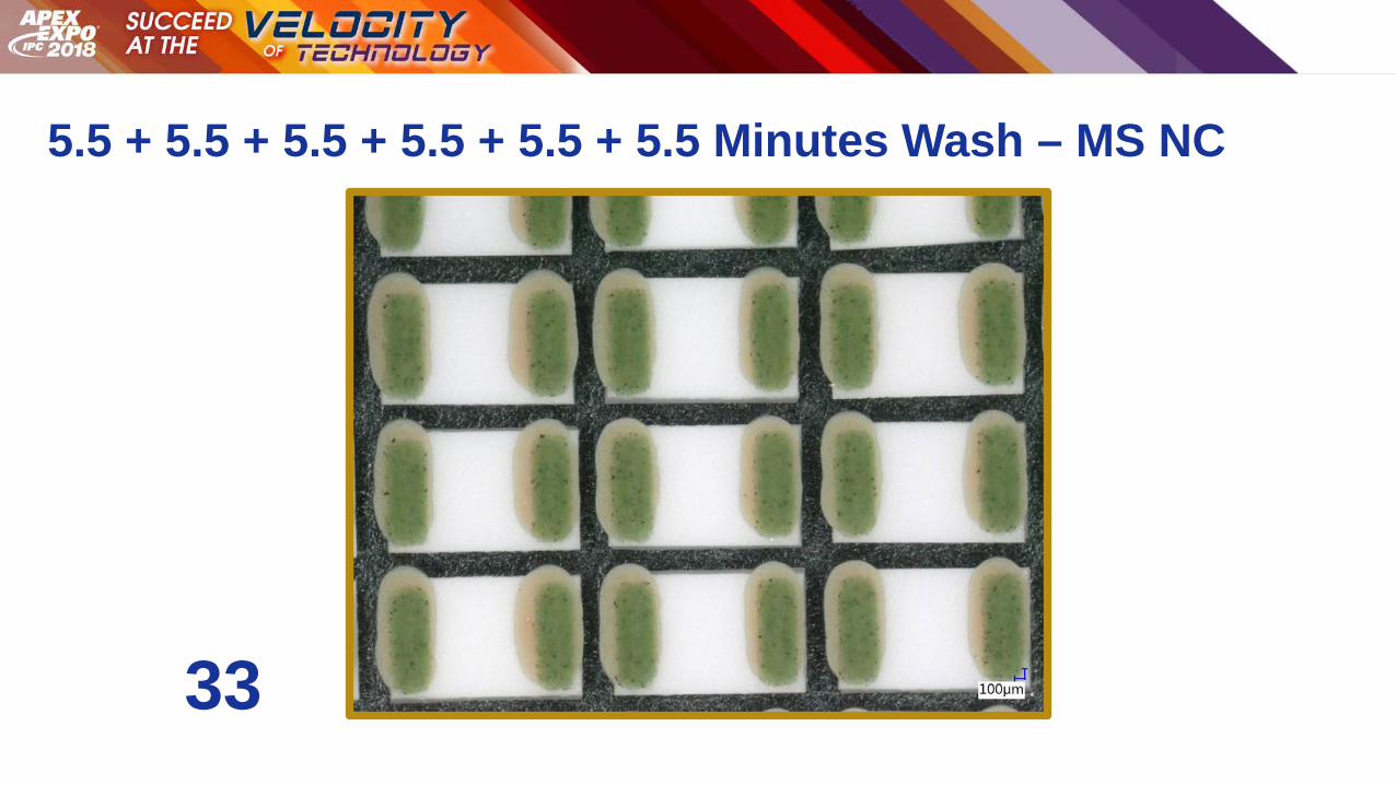
5.5 + 5.5 + 5.5 + 5.5 + 5.5 + 5.5 Minutes Wash – MS NC
33

Dishwasher Style MachineData Findings

Dishwasher Style Cleaning Machine
AOI of One of the Soluble No-Clean Pastes

Comparison of the Two Machines
6.05.03.52.00.0
1 00
80
60
40
20
0
Wash Time Accumulated in Minutes per Wash Cycle
0 =
Tot
ally
Cle
an; 1
00 =
Tot
ally
Dirt
y DishwasherSpray-in-Air
Batch Machine
Interaction Plot for Water Soluble Flux under 0805 ComponentsData Means

Inferences from the Data Findings
Solder Pastes Cleanability
■ Cleanability of the flux residue varies
Water Soluble Solder Paste • Less than 5 minutes of wash time in both machine types
Soluble No-Clean Solder Paste • Wash time ranges from 10-15 minutes using direct spray-in-air design
• Wash time ranges from 20 -25 minutes using dishwasher style design
Marginally Soluble No-Clean Solder Paste • Wash time ranges from 25-35 minutes using direct spray-in-air design
• Wash time of greater than 40 minutes still left residue using dishwasherstyle design
Cleaning Agent
■ Static Cleaning Rate for the Residue
Impacts the time to clean■ Next generation aqueous cleaning agent
Removes all flux types Wide compatibility profile
■ Wash temperature improves cleaning rate
■ Wash concentration can improve cleaning rate
Cleaning Machine
■ Highly dense leadless components are harder to clean
■ As the standoff gap reduces
Contamination under component increases Higher deflective energy is needed
■ Cleaning machines with stronger deflective forces
Create forces needed to penetrate, create a flow under the component and remove residue
■ Cleaning machines with high flow / low deflection forces
Clean surface residues well Poor at penetrating and creating flow under low gaps
Ceramic / Glass Test Vehicle
■ Can be used to dial in process factors
■ Residue under component is visible
■ AOI instrumentation can be used to quantitatively determine residue levels post cleaning
■ Test vehicle can be processed multiple wash cycles to determine time to clean
■ Test vehicle can be cleaned and reused for other trials

Conclusions
Cleaning in Electronics
■ Black Art
Hard to quantify without part removal to know levels of residues under leadless components
Residue not detectable visually can lead to a false/positive condition
■ Visible residue with minimal electrical clearance can cause reliability risks
■ Both cleaning machine and cleaning agent may leave undetectable residues under leadless components
Visual Evidence
■ Provides the assembler with an accurate metric for
Dialing in the process Cleaning all visual residues under leadless components
■ Test vehicles helps the process engineer to test for
Cleaning machine setting Cleaning machine types Wash chemistry Wash parameters