
Clean Agent - SFFECO Clean agent fire extinguishing system consists of a series of appropriately...
28
www. SFFECO.com 9 Suppress fire quickly 9 Restricted damages 9 Limited floor space 9 Allow Visibility Clean Agent Fire Extinguishing System
Transcript of Clean Agent - SFFECO Clean agent fire extinguishing system consists of a series of appropriately...

www.SFFECO.com
9 Suppress fire quickly 9 Restricted damages 9 Limited floor space 9 Allow Visibility
Clean AgentFire Extinguishing System

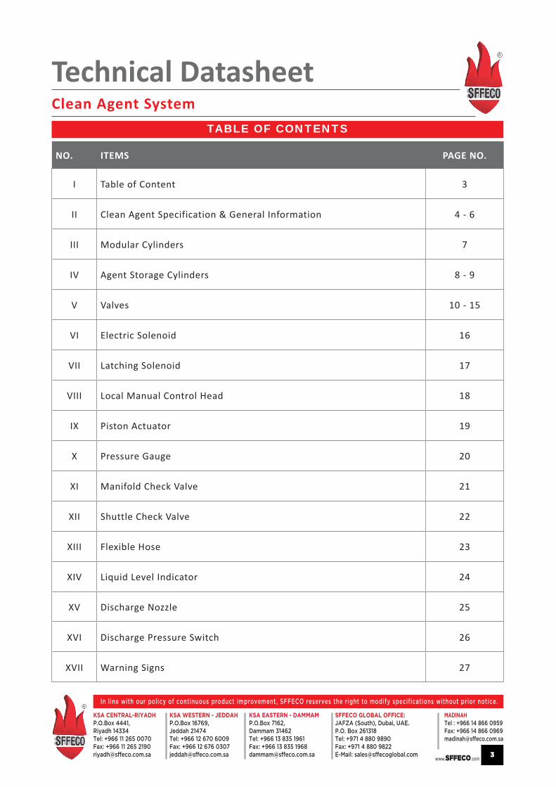
TABLE OF CONTENTS
NO. ITEMS PAGE NO.
I Table of Content 3
II Clean Agent Specification & General Information 4 - 6
III Modular Cylinders 7
IV Agent Storage Cylinders 8 - 9
V Valves 10 - 15
VI Electric Solenoid 16
VII Latching Solenoid 17
VIII Local Manual Control Head 18
IX Piston Actuator 19
X Pressure Gauge 20
XI Manifold Check Valve 21
XII Shuttle Check Valve 22
XIII Flexible Hose 23
XIV Liquid Level Indicator 24
XV Discharge Nozzle 25
XVI Discharge Pressure Switch 26
XVII Warning Signs 27
Technical DatasheetClean Agent System
www.SFFECO.com
In line with our policy of continuous product improvement, SFFECO reserves the right to modify specifications without prior notice.
KSA CENTRAL-RIYADHP.O.Box 4441,Riyadh 14334Tel: +966 11 265 0070Fax: +966 11 265 [email protected]
KSA EASTERN - DAMMAMP.O.Box 7162,Dammam 31462Tel: +966 13 835 1961Fax: +966 13 835 [email protected]
KSA WESTERN - JEDDAHP.O.Box 16769,Jeddah 21474Tel: +966 12 670 6009Fax: +966 12 676 [email protected]
MADINAH Tel : +966 14 866 0959Fax: +966 14 866 [email protected]
SFFECO GLOBAL OFFICE:JAFZA (South), Dubai, UAE.P.O. Box 261318Tel: +971 4 880 9890Fax: +971 4 880 9822E-Mail: [email protected] 3

SPECIFICATIONAPPLICATIONHeptafluoropropane (CF3CHFCF3) fire suppression agent is the first environmentally acceptable replacement for Halon 1301. It has zero ozone depleting potential, a low global warming potential, and a short atmospheric lifetime. It is particularly useful where an environmentally acceptable agent is essential, where clean-up of other media presents a problem, where weight versus suppression potential is a factor, where an electrically non-conductive medium is needed, and where people compatibility is an overriding factor. Clean Agent can be used to protect a wide range of applications from sensitive electrical equipment to industrial applications using flammable liquids. Consult the current NFPA Standard 2001 for specific applications. Clean Agent fire suppression agent is used with SFFECO’s total flooding systems.
DESCRIPTIONClean Agent is an odorless, colorless, liquefied compressed gas. (See Physical Properties Table for additional information). It is stored as a liquid and dispensed into the hazard as a colorless, electrically non-conductive vapor that is clear and does not obscure vision. It leaves no residue and has acceptable toxicity for use in occupied spaces at design concentration. Clean Agent extinguishes a fire by a combination of chemical and physical mechanisms. Clean Agent does not displace oxygen and therefore is safe for use in occupied spaces without fear of oxygen deprivation.
PERFORMANCEClean Agent can be used on many types of fires. It is effective for many surface fires, such as flammable liquids, and most solid combustible materials.
On a weight-of-agent basis, clean agent is a very effective gaseous extinguishing agent. The Clean Agent extinguishing concentration for normal Class A combustibles is approximately 5.8 - 7% by volume. The minimum design concentration for total flood applications should be in accordance with NFPA 2001.
SPECIFICATION
Clean Agent is manufactured to these specifications:
Mole% 99.0 Min.
Acidity, ppm by weight 3.0 Max.
Water content, % by weight 0.001 Max.
Non-volatile residues,gram/100Ml 0.05 Max.
TOXICITYThe toxicology of Clean Agent compares favorable with that of Halon 1301. The LC50 of Clean Agent is greater than 800,000 ppm which is equivalent to Halon 1301. Clean Agent has been evaluated for cardiac sensitization via test protocols approved by the United States Environmental Protection Agency. Test results show that cardiac tolerance to Clean Agent is much higher than that of Halon 1301 and will be acceptable for safe use in occupied space protection. Clean Agent will decompose to form halogen acids when exposed to open flames. The formation of these acids is minimized by using SFFECO early warning detection systems and proper system installation. When properly applied and installed, the generation of these by-products by Clean Agent should be minimal.
Technical DatasheetClean Agent System
www.SFFECO.com
In line with our policy of continuous product improvement, SFFECO reserves the right to modify specifications without prior notice.
KSA CENTRAL-RIYADHP.O.Box 4441,Riyadh 14334Tel: +966 11 265 0070Fax: +966 11 265 [email protected]
KSA EASTERN - DAMMAMP.O.Box 7162,Dammam 31462Tel: +966 13 835 1961Fax: +966 13 835 [email protected]
KSA WESTERN - JEDDAHP.O.Box 16769,Jeddah 21474Tel: +966 12 670 6009Fax: +966 12 676 [email protected]
MADINAH Tel : +966 14 866 0959Fax: +966 14 866 [email protected]
SFFECO GLOBAL OFFICE:JAFZA (South), Dubai, UAE.P.O. Box 261318Tel: +971 4 880 9890Fax: +971 4 880 9822E-Mail: [email protected] 4

Chemical Name Heptafluoropropane (CF3CHFCF3)Molecular Weight 170.03Boiling Point @ 760 mm Hg 2.55OF (-16.4OC)Freezing Point -204OF (-131.1OC)
Critical Temperature 215OF (101.7OC)Critical Pressure (psia) 422 psia (2912 kPa)Critical Volume (ft3/lbm) (cc/mole) 0.0258 (274)Critical Density (lbm/ft3) 38.8 (621 kg/m3)Specific Heat, Liquid (BTU/lb-OF) @ 77OF (25OC) 0.283 (1.184 kj/kg/OC)Specific Heat, Vapor (BTU/lb-OF) @ constant
pressure of 1 ATM @ 77OF (25OC)
0.1932 (0.808 kj/kg/OC)
Heat at Vaporization (BTU/lb)
at Boiling Point
57.0 (132.6 kj/kg)
Thermal Conductivity (BTU/h ftOF)
of Liquid @ 77OF (25OC)
0.040 (0.069 w/mOC)
Viscosity, Liquid (lb/ft hr) @ 77OF (25OC) 0.443 (0.184 centipoise)
Vapor Pressure (psia) @ 77OF (25OC) 66.4 (457.7 kPa)Ozone Depletion Potential 0Est. Atmospheric Lifetime (years) 31-42LC50 (Rats; 4hrs - ppm) >800,000
Agent Use Conc. NOAEL* Safety MarginHalon 1301 5% 5% nilFM 200 7.5 - 8.7% 9% 3% - 20%NovecTM 1230 5 - 6% 10% 67% - 100%
Inergen 38 - 40% 43% 7% - 13%CO2 30 - 75% <5% lethal at design concs
* No observable adverse effect level.
PHYSICAL PROPERTIES OF CLEAN AGENT
SAFETY CONSIDERATIONS
Technical DatasheetClean Agent System
www.SFFECO.com
In line with our policy of continuous product improvement, SFFECO reserves the right to modify specifications without prior notice.
KSA CENTRAL-RIYADHP.O.Box 4441,Riyadh 14334Tel: +966 11 265 0070Fax: +966 11 265 [email protected]
KSA EASTERN - DAMMAMP.O.Box 7162,Dammam 31462Tel: +966 13 835 1961Fax: +966 13 835 [email protected]
KSA WESTERN - JEDDAHP.O.Box 16769,Jeddah 21474Tel: +966 12 670 6009Fax: +966 12 676 [email protected]
MADINAH Tel : +966 14 866 0959Fax: +966 14 866 [email protected]
SFFECO GLOBAL OFFICE:JAFZA (South), Dubai, UAE.P.O. Box 261318Tel: +971 4 880 9890Fax: +971 4 880 9822E-Mail: [email protected] 5

SYSTEM IN GENERAL
The Clean agent fire extinguishing system
consists of a series of appropriately sized valves
and cylinders that utilize HFC227ea as the
extinguishing medium. Each system consists
of five basic components and their associated
accessories.
1. HFC227ea Storage Components
2. HFC227ea Distribution Components
3. Trim Components
4. Slave Arrangement Components
5. Supplemental Components
6. Control Panel
7. Early Warning Detection and alarm Devices
Technical DatasheetClean Agent System
www.SFFECO.com
In line with our policy of continuous product improvement, SFFECO reserves the right to modify specifications without prior notice.
KSA CENTRAL-RIYADHP.O.Box 4441,Riyadh 14334Tel: +966 11 265 0070Fax: +966 11 265 [email protected]
KSA EASTERN - DAMMAMP.O.Box 7162,Dammam 31462Tel: +966 13 835 1961Fax: +966 13 835 [email protected]
KSA WESTERN - JEDDAHP.O.Box 16769,Jeddah 21474Tel: +966 12 670 6009Fax: +966 12 676 [email protected]
MADINAH Tel : +966 14 866 0959Fax: +966 14 866 [email protected]
SFFECO GLOBAL OFFICE:JAFZA (South), Dubai, UAE.P.O. Box 261318Tel: +971 4 880 9890Fax: +971 4 880 9822E-Mail: [email protected] 6

MODULAR CYLINDERS
Technical DatasheetClean Agent System
www.SFFECO.com
In line with our policy of continuous product improvement, SFFECO reserves the right to modify specifications without prior notice.
KSA CENTRAL-RIYADHP.O.Box 4441,Riyadh 14334Tel: +966 11 265 0070Fax: +966 11 265 [email protected]
KSA EASTERN - DAMMAMP.O.Box 7162,Dammam 31462Tel: +966 13 835 1961Fax: +966 13 835 [email protected]
KSA WESTERN - JEDDAHP.O.Box 16769,Jeddah 21474Tel: +966 12 670 6009Fax: +966 12 676 [email protected]
MADINAH Tel : +966 14 866 0959Fax: +966 14 866 [email protected]
SFFECO GLOBAL OFFICE:JAFZA (South), Dubai, UAE.P.O. Box 261318Tel: +971 4 880 9890Fax: +971 4 880 9822E-Mail: [email protected] 7
MODEL SFM 10 SFM 15 SFM 20 SFM 25 SFM 30 SFM 35 SFM 40 SFM 45
CYLINDER SIZE(LTR) 10 15 20 25 30 35 40 45
AGENT WEIGHT (KG) 11 16 22 28 33 39 44 50
MINIMUM CAPACITY (L) 6 9 12 15 18 21 24 27
MAXIMUM CAPACITY (L) 11 16.5 22 27.5 33 38.5 44 49.5
PRESSURE (BAR) 20 20 20 20 20 20 20 20
DISCH DURATION 8 6 8 10 6 7 8 9
VOLUME PROTECTED WITH 7% CONC. @ 20°C
20 CU MTR
30 CU MTR
41 CU MTR.
51 CU MTR
61 CU MTR
72 CU MTR
82 CU MTR
92 CU MTR
TEMP. RATING 57OC / 68OC / 79OC / 93OC / 141OC
DESCRIPTION
SFM modular series is a self-contained stand alone system, ideally economical, simple and flexible to suit pre-prevailing local conditions. The Design concept of operation features the sprinkler technology incorporating a gas tight quartzoid bulb sprinkler head fitted with a pyrotechnic electric actuator, 24 vdc, means of actuating the system can be from a remote controlled release fire extinguishing control panel or thermally fusing the glass bulb which comes in various fixed temperature ranges.
SFM modular cylinders furnished with ceiling mounting brackets are of carbon steel material, factory argon/CO2 weld, sand blasted, epoxy primed, white finished, oven baked and coated with electrostatic powder are constructed to comply fully with BS 5045, class 1A and BS 4800.
SFM extinguishment chemically known as heptaflouropropane (CF3CHFCF3) is a clean and effective environmentally accepted replacement for halon. It is effective fire extinguishing agent that can be used on surface fire of flammable liquids and solid combustible materials. Likewise, effective for total flooding of normally occupied areas to protect the highly invested equipment.
SFM modular automatic installations are primarily well-suited for the protection of oil furnaces and heating paint spray booths, flammable liquid storage areas, engine compartment in particular for boats, other work installations and small rooms that are particularly exposed to danger of fire. Cylinders are hydrostatically tested at 1000 psi.

AGENT STORAGE CYLINDERS
Technical DatasheetClean Agent System
www.SFFECO.com
In line with our policy of continuous product improvement, SFFECO reserves the right to modify specifications without prior notice.
KSA CENTRAL-RIYADHP.O.Box 4441,Riyadh 14334Tel: +966 11 265 0070Fax: +966 11 265 [email protected]
KSA EASTERN - DAMMAMP.O.Box 7162,Dammam 31462Tel: +966 13 835 1961Fax: +966 13 835 [email protected]
KSA WESTERN - JEDDAHP.O.Box 16769,Jeddah 21474Tel: +966 12 670 6009Fax: +966 12 676 [email protected]
MADINAH Tel : +966 14 866 0959Fax: +966 14 866 [email protected]
SFFECO GLOBAL OFFICE:JAFZA (South), Dubai, UAE.P.O. Box 261318Tel: +971 4 880 9890Fax: +971 4 880 9822E-Mail: [email protected] 8
CYLINDER BRACKETCYLINDER DIMENSION
FLOOR STRAP
WALL STRAP
D
EF
EF
DG
G
C
OCI 60790
OCI 60772
DiameterType
SF 60790
SF 60772
30.0''
30.0''
30.225'' 35.2'' 33.2''
5'' 11.85'' 10.35''
D E F G
2''
2''
CYLINDER BRACKETCYLINDER DIMENSION
FLOOR STRAP
WALL STRAP
D
EF
EF
DG
G
C
OCI 60790
OCI 60772
DiameterType
SF 60790
SF 60772
30.0''
30.0''
30.225'' 35.2'' 33.2''
5'' 11.85'' 10.35''
D E F G
2''
2''
DESCRIPTION
The Clean Agent cylinders are filled with one pound increments, as given in the Table-1, to meet the exact amount of agent required. The quantity of agent required for each enclosure can be calculated using SFFECO software, version SF 3.10 (or 4.0), which contains a sophisticated calculation routine for predicting the two-phase as well as two-component flow of agent and nitrogen through the distribution piping network in quasi-steady state from the initiation of the discharge to final gas blow down. The cylinder is then super-pressurized with dry nitrogen to 360 psi at 70°F to provide extinguishment in 10 seconds or less. The 4’’ stainless steel valve offers excellent flow characteristics for the liquefied gas, allows for long pipe runs and has a greater coverage area. This is the largest Clean Agent cylinder currently manufactured and designed for very large applications. The 1200 lb, 1000 lb and 800 lb. cylinders are manufactured, tested and stamped in accordance with DOT 4BW500.
Temperature Limits: 32°F (0°C) to 130°F (54.4°C)
System Operating Pressure: 360 psi at 70°F (25.3 kgƒ/cm²at 21.1°C)
CYLINDER BRACKET
The cylinder bracket is manufactured from carbon steel band formed to the radius of the cylinder as shown in Table-2, with flanges for bolting to continuous slot metal framing channel of 12 gauge steel with corrosion resistant paint or galvanized. The channel is to be supplied by the installer. The cylinder bracket shall be secured to a surface that the bracket, that will withstand a load up to 5 times of the cylinder weight. This precaution is to have the bracket safely support the weight of the cylinder and the reaction force of the HFC-227 ea Clean Agent when discharge.
TABLE-1: CYLINDER FILLING DATA & DIMENSIONS
TABLE-2: CYLINDER BRACKET (WALL AND FLOOR STRAP)
Model Capacity Fill Capacity Valve A B C
SFO 20-800 800 Lbs 353 to 806 lbs 4" 56.701” 47.023” 27.76”
SFO 20-1000 1000 Lbs 439 to 1008 lbs 4" 64.049” 54.381” 27.76”
SFO 20-1200 1200 Lbs 519 to 1211 lbs 4" 71.516” 61.726” 27.76”

AGENT STORAGE CYLINDERS
Technical DatasheetClean Agent System
www.SFFECO.com
In line with our policy of continuous product improvement, SFFECO reserves the right to modify specifications without prior notice.
KSA CENTRAL-RIYADHP.O.Box 4441,Riyadh 14334Tel: +966 11 265 0070Fax: +966 11 265 [email protected]
KSA EASTERN - DAMMAMP.O.Box 7162,Dammam 31462Tel: +966 13 835 1961Fax: +966 13 835 [email protected]
KSA WESTERN - JEDDAHP.O.Box 16769,Jeddah 21474Tel: +966 12 670 6009Fax: +966 12 676 [email protected]
MADINAH Tel : +966 14 866 0959Fax: +966 14 866 [email protected]
SFFECO GLOBAL OFFICE:JAFZA (South), Dubai, UAE.P.O. Box 261318Tel: +971 4 880 9890Fax: +971 4 880 9822E-Mail: [email protected] 9
CylinderModel
CylinderOuter Dia. D E F G Bracket Part
No.10.75" 11.00" 14.00" 12.60" 2.00" OCI 5013910.75" 11.00" 14.00" 12.60" 2.00" OCI 5013910.75" 11.00" 14.00" 12.60" 2.00" OCI 5013912.80" 13.00" 16.05" 14.65" 2.00" OCI 6078012.80" 13.00" 16.05" 14.65" 2.00" OCI 6078016.00" 16.25" 19.20" 17.80" 2.00" OCI 6076016.00" 16.25" 19.20" 17.80" 2.00" OCI 6076020.00" 20.25" 23.20" 21.70" 2.00" OCI 60770
CB
A
E
F
D
G
FOAM TAPE
CYLINDER BRACKET DIMENSIONS
SFO 20-20SFO 20-35SFO 20-70SFO 20-100SFO 20-150SFO 20-250SFO 20-375SFO 20-560
DESCRIPTION
The Clean Agent cylinders are manufactured, tested and stamped in accordance with DOT 4BW500 or DOT 4BA500. All cylinders are equipped with differential pressure valve. A piston in the valve bore is equipped with a rubber seal that keeps the HFC-227ea Clean Agent under pressure within the cylinder. Since the area at the top of the piston is greater than the area at the bottom of the piston, the net force seals the piston against the valve discharge outlet. When the cylinder pressure on the top of the piston is relieved by means of automatic or manual activation, there is only cylinder pressure acting against the piston seal, and the piston slide to full open position, allowing cylinder discharge through the distribution piping network. Each of the basic sizes can be filled with one pound increments to meet the exact amount of HFC-227ea Clean Agent required, within their fill ranges as shown in the table below.
TEMPERATURE LIMITS: 32°F (0°C)to 130°F (54.4°C)
SYSTEM OPERATING PRESSURE: 360 psi at 70°F (25.3 kgƒ/cm² at 21.1°C )
CYLINDER BRACKET
The cylinder bracket is manufactured from carbon steel band formed to the radius of the cylinder as shown in Table-3 with flanges for bolting to continuous slot metal framing channel of 12-gauge steel with corrosion resistant paint or galvanized. The channel shall be supplied by the installer. The cylinder bracket shall be secured to a surface that, the bracket will withstand a load up to 5 times of the cylinder weight. This precaution is to have the bracket safely support the weight of the cylinder and the reaction force of the HFC-227ea Clean Agent when discharged.
Model Capacity Fill Capacity Valve A B CSFO 20-20 20 Lbs 12 to 20 lbs 1" 10.75” 13.8” 18.5”SFO 20-35 35 Lbs 16 to 35 1" 10.75” 18.7” 23.5”SFO 20-70 70 Lbs 36 to 71 lbs 1" 10.75” 27.2” 31.9”
SFO 20-100 100 Lbs 44 to 101 lbs 1-1/2” 12.8” 28” 32.9”SFO 20-150 150 Lbs 71 to 152 lbs 1-1/2" 12.8” 37.4” 42.9”SFO 20-250 250 Lbs 153 to 253 lbs 1-1/2" 16” 39.8” 42.9”SFO 20-375 375 Lbs 254 to 379 lbs 2-1/2" 16” 57.1” 64.9”SFO 20-560 560 Lbs 380 to 561 lbs 2-1/2" 20” 55.7” 63.6”
CYLINDER FILLING DATA AND DIMENSIONS
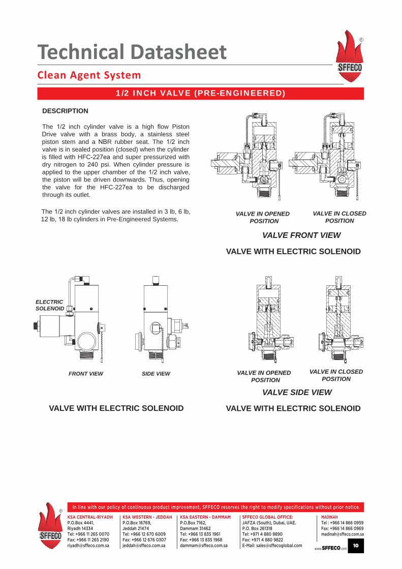
1/2 INCH VALVE (PRE-ENGINEERED)
Technical DatasheetClean Agent System
www.SFFECO.com
In line with our policy of continuous product improvement, SFFECO reserves the right to modify specifications without prior notice.
KSA CENTRAL-RIYADHP.O.Box 4441,Riyadh 14334Tel: +966 11 265 0070Fax: +966 11 265 [email protected]
KSA EASTERN - DAMMAMP.O.Box 7162,Dammam 31462Tel: +966 13 835 1961Fax: +966 13 835 [email protected]
KSA WESTERN - JEDDAHP.O.Box 16769,Jeddah 21474Tel: +966 12 670 6009Fax: +966 12 676 [email protected]
MADINAH Tel : +966 14 866 0959Fax: +966 14 866 [email protected]
SFFECO GLOBAL OFFICE:JAFZA (South), Dubai, UAE.P.O. Box 261318Tel: +971 4 880 9890Fax: +971 4 880 9822E-Mail: [email protected] 10
ELECTRICSOLENOID
VALVE WITH ELECTRIC SOLENOID
FRONT VIEW
VALVE WITH ELECTRIC SOLENOID
VALVE WITH ELECTRIC SOLENOID
DESCRIPTION
The inch cylinder valve is a high flow Pistonive valve with a brass body, a stainless steel
piston stem and a R rubber seat. The inchvalve is in sealed position (closed) when the cylinderis filled with HFC-2 and super pressurized withdry nitrogen to psi. When cylinder pressure isapplied to the upper chamber of the inch valve,the piston will be driven downwards. Thus, openingthe valve for the HFC-22 to be dischargedthrough its outlet.
The inch cylinder valves are installed in lb, lb,1 lb cylinders in Pre-Engineered Systems.
VALVE IN OPENED POSITION
VALVE IN CLOSED POSITION
VALVE IN OPENED POSITION
VALVE IN CLOSED POSITION
SIDE VIEW
VALVE SIDE VIEW
VALVE FRONT VIEW
Technical DatasheetClean Agent System
www.SFFECO.com
In line with our policy of continuous product improvement, SFFECO reserves the right to modify specifications without prior notice.
KSA CENTRAL-RIYADHP.O.Box 4441,Riyadh 14334Tel: +966 11 265 0070Fax: +966 11 265 [email protected]
KSA EASTERN - DAMMAMP.O.Box 7162,Dammam 31462Tel: +966 13 835 1961Fax: +966 13 835 [email protected]
KSA WESTERN - JEDDAHP.O.Box 16769,Jeddah 21474Tel: +966 12 670 6009Fax: +966 12 676 [email protected]
MADINAH Tel : +966 14 866 0959Fax: +966 14 866 [email protected]
SFFECO GLOBAL OFFICE:JAFZA (South), Dubai, UAE.P.O. Box 261318Tel: +971 4 880 9890Fax: +971 4 880 9822E-Mail: [email protected] 11
VALVE WITH ELECTRIC SOLENOID
FRONT VIEW
ELECTRICSOLENOID
VALVE SIDE VIEW
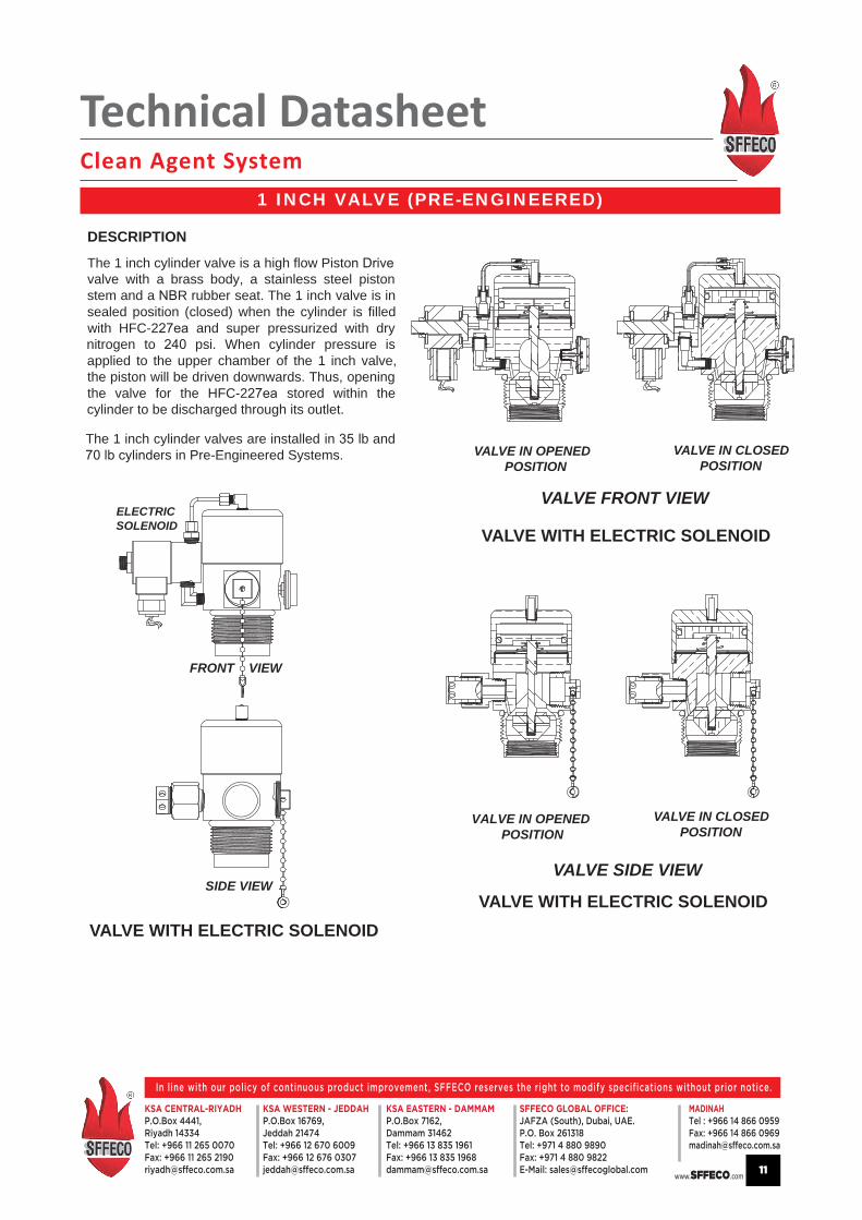
DESCRIPTIONThe 1 inch cylinder valve is a high flow Pistovalve with a brass body, a stainless steel pistonstem and a R rubber seat. The 1 inch valve is insealed position (closed) when the cylinder is filledwith HFC-2 and super pressurized with drynitrogen to psi. When cylinder pressure isapplied to the upper chamber of the 1 inch valve,the piston will be driven downwards. Thus, openingthe valve for the HFC-2 stored within thecylinder to be discharged through its outlet.
The 1 inch cylinder valves are installed in lb andrs in Pre-Engineered Systems.
VALVE IN OPENED POSITION
VALVE IN CLOSED POSITION
VALVE IN OPENED POSITION
VALVE IN CLOSED POSITION
SIDE VIEW
VALVE FRONT VIEW
VALVE WITH ELECTRIC SOLENOID
VALVE WITH ELECTRIC SOLENOID
1 INCH VALVE (PRE-ENGINEERED)
Technical DatasheetClean Agent System
www.SFFECO.com
In line with our policy of continuous product improvement, SFFECO reserves the right to modify specifications without prior notice.
KSA CENTRAL-RIYADHP.O.Box 4441,Riyadh 14334Tel: +966 11 265 0070Fax: +966 11 265 [email protected]
KSA EASTERN - DAMMAMP.O.Box 7162,Dammam 31462Tel: +966 13 835 1961Fax: +966 13 835 [email protected]
KSA WESTERN - JEDDAHP.O.Box 16769,Jeddah 21474Tel: +966 12 670 6009Fax: +966 12 676 [email protected]
MADINAH Tel : +966 14 866 0959Fax: +966 14 866 [email protected]
SFFECO GLOBAL OFFICE:JAFZA (South), Dubai, UAE.P.O. Box 261318Tel: +971 4 880 9890Fax: +971 4 880 9822E-Mail: [email protected] 12
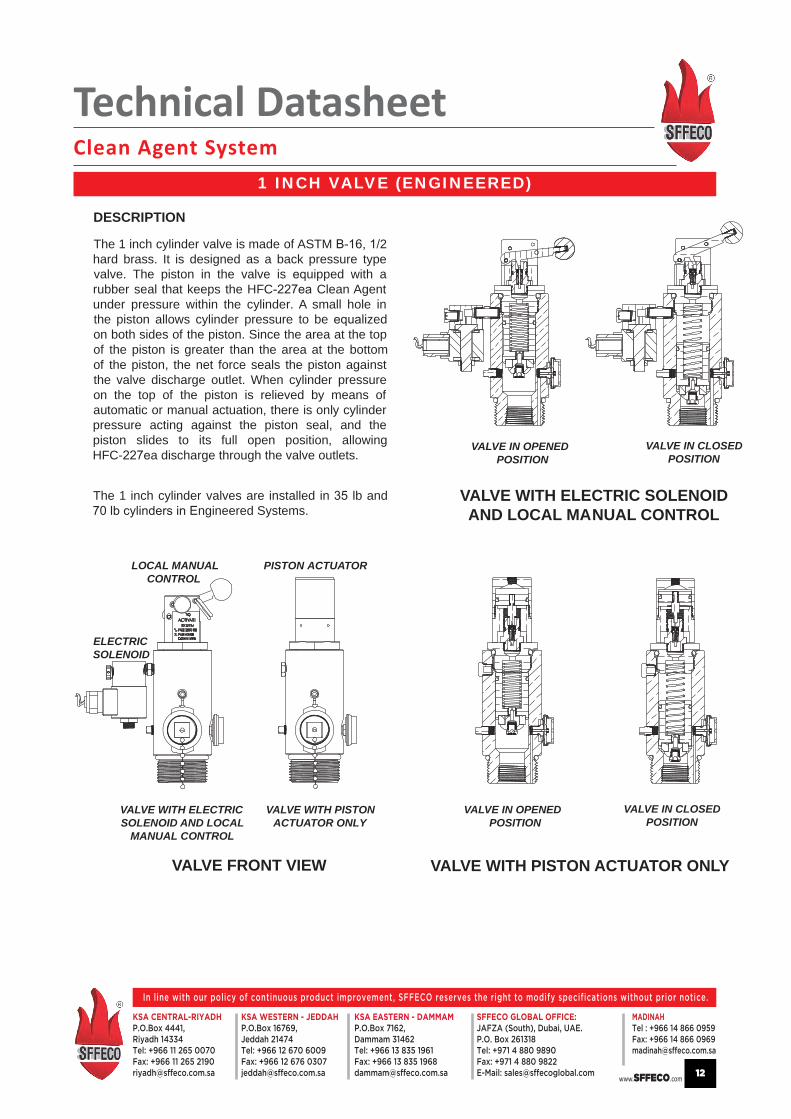
DESCRIPTION
VALVE FRONT VIEW
PISTON ACTUATORLOCAL MANUAL CONTROL
ELECTRICSOLENOID
VALVE WITH ELECTRIC SOLENOID AND LOCAL MANUAL CONTROL
VALVE WITH PISTON ACTUATOR ONLY
The 1 inch cylinder valves are installed in lb andngineered Systems.
The 1 inch cylinder valve is made of ASTM 2hard brass. It is designed as a back pressure typevalve. The piston in the valve is uipped with arubber seal that keeps the HFC Clean Agentunder pressure within the cylinder. A small hole inthe piston allows cylinder pressure to be lizedon both sides of the piston. Since the area at the topof the piston is greater than the area at the bottomof the piston, the net force seals the piston againstthe valve discharge outlet. When cylinder pressureon the top of the piston is relieved by means ofautomatic or manual actuation, there is only cylinderpressure acting against the piston seal, and thepiston slides to its full open position, allowingHFC- a discharge through the valve outlets.
VALVE IN OPENED POSITION
VALVE IN CLOSED POSITION
VALVE IN OPENED POSITION
VALVE IN CLOSED POSITION
VALVE WITH ELECTRICSOLENOID AND LOCAL MANUAL CONTROL
VALVE WITH PISTON ACTUATOR ONLY
1 INCH VALVE (ENGINEERED)

Technical DatasheetClean Agent System
www.SFFECO.com
In line with our policy of continuous product improvement, SFFECO reserves the right to modify specifications without prior notice.
KSA CENTRAL-RIYADHP.O.Box 4441,Riyadh 14334Tel: +966 11 265 0070Fax: +966 11 265 [email protected]
KSA EASTERN - DAMMAMP.O.Box 7162,Dammam 31462Tel: +966 13 835 1961Fax: +966 13 835 [email protected]
KSA WESTERN - JEDDAHP.O.Box 16769,Jeddah 21474Tel: +966 12 670 6009Fax: +966 12 676 [email protected]
MADINAH Tel : +966 14 866 0959Fax: +966 14 866 [email protected]
SFFECO GLOBAL OFFICE:JAFZA (South), Dubai, UAE.P.O. Box 261318Tel: +971 4 880 9890Fax: +971 4 880 9822E-Mail: [email protected] 13
VALVE WITH ELECTRIC SOLENOID AND LOCAL MANUAL CONTROL
VALVE WITH PISTON ACTUATOR ONLYVALVE FRONT VIEW
PISTON ACTUATORLOCAL MANUAL CONTROL
ELECTRICSOLENOID
DESCRIPTIONThe 1 inch cylinder valve is made of ASTM -
hard brass. It is designed as a back pressuretype valve. The piston in the valve is arubber seal that keeps the ea Clean Agentunder pressure within the cylinder. A small hole inthe piston allows cylinder pressure to be on both sides of the piston. Since the area at the topof the piston is greater than the area at the bottomof the piston, the net force seals the piston againstthe valve discharge outlet. When cylinder pressureon the top of the piston is relieved by means ofautomatic or manual actuation, there is only cylinderpressure acting against the piston seal, and thepiston slides to its full open position, allowing
discharge through the valve outlets.
The 1 inch cylinder valves are installed in lbylinders in Engineered Systems and
linders in Pre-Engineered Systems.
VALVE WITH ELECTRICSOLENOID AND LOCAL MANUAL CONTROL
VALVE WITH PISTON ACTUATOR ONLY
VALVE IN OPENED POSITION
VALVE IN CLOSED POSITION
VALVE IN OPENED POSITION
VALVE IN CLOSED POSITION
1.5 INCH CYLINDER VALVE

Technical DatasheetClean Agent System
www.SFFECO.com
In line with our policy of continuous product improvement, SFFECO reserves the right to modify specifications without prior notice.
KSA CENTRAL-RIYADHP.O.Box 4441,Riyadh 14334Tel: +966 11 265 0070Fax: +966 11 265 [email protected]
KSA EASTERN - DAMMAMP.O.Box 7162,Dammam 31462Tel: +966 13 835 1961Fax: +966 13 835 [email protected]
KSA WESTERN - JEDDAHP.O.Box 16769,Jeddah 21474Tel: +966 12 670 6009Fax: +966 12 676 [email protected]
MADINAH Tel : +966 14 866 0959Fax: +966 14 866 [email protected]
SFFECO GLOBAL OFFICE:JAFZA (South), Dubai, UAE.P.O. Box 261318Tel: +971 4 880 9890Fax: +971 4 880 9822E-Mail: [email protected] 14
DESCRIPTION
VALVE IN OPENED POSITION
VALVE WITH ELECTRIC SOLENOID AND LOCAL MANUAL CONTROL
VALVE IN CLOSED POSITION
VALVE IN OPENED POSITION
VALVE IN CLOSED POSITION
VALVE WITH PISTON ACTUATOR ONLYVALVE FRONT VIEW
VALVE WITH ELECTRICSOLENOID AND LOCAL MANUAL CONTROL
VALVE WITH PISTON ACTUATOR ONLY
PISTON ACTUATORLOCAL MANUAL CONTROL
ELECTRICSOLENOID
The 2 inch cylinder valve is made of ASTM hard brass. It is designed as a back pressure
type valve. The piston in uipped with arubber seal that keeps the HFC-2 Clean Agentunder pressure within the cylinder. A small hole inthe piston allows cylinder pressure to be eon both sides of the piston. Since the area at the topof the piston is greater than the area at the bottomof the piston, the net force seals the piston againstthe valve discharge outlet. When cylinder pressureon the top of the piston is relieved by means ofautomatic or manual actuation, there is only cylinderpressure acting against the piston seal, and thepiston slides to its full open position, allowing
ea discharge through the valve outlets.
The 2 inch cylinder valves are installed in lband lb cylinders in Engineered Systems and
lb and lb cylinders in Pre-EngineeredSystems.
2.5 INCH CYLINDER VALVE

Technical DatasheetClean Agent System
www.SFFECO.com
In line with our policy of continuous product improvement, SFFECO reserves the right to modify specifications without prior notice.
KSA CENTRAL-RIYADHP.O.Box 4441,Riyadh 14334Tel: +966 11 265 0070Fax: +966 11 265 [email protected]
KSA EASTERN - DAMMAMP.O.Box 7162,Dammam 31462Tel: +966 13 835 1961Fax: +966 13 835 [email protected]
KSA WESTERN - JEDDAHP.O.Box 16769,Jeddah 21474Tel: +966 12 670 6009Fax: +966 12 676 [email protected]
MADINAH Tel : +966 14 866 0959Fax: +966 14 866 [email protected]
SFFECO GLOBAL OFFICE:JAFZA (South), Dubai, UAE.P.O. Box 261318Tel: +971 4 880 9890Fax: +971 4 880 9822E-Mail: [email protected] 15
VALVE ELEVATION VIEW
DESCRIPTION
The 4 inch cylinder valve is made of Stainless Steel. It is designed as a back pressuretype valve. The piston in the valve is arubber seal that keeps the HFC Clean Agentunder pressure within the cylinder. A small hole inthe piston allows cylinder pressure to be lizedon both sides of the piston. Since the area at the topof the piston is greater than the area at the bottomof the piston, the net force seals the piston againstthe valve discharge outlet. When cylinder pressureon the top of the piston is relieved by means ofautomatic or manual actuation, there is only cylinderpressure acting against the piston seal, and thepiston slides to its full open position, allowingHFC- a discharge through the valve outlets.
The 4 inch cylinder valves are installed in 1 lbcylinders in Engineered Systems.
VALVE WITH ELECTRICSOLENOID AND LOCAL MANUAL CONTROL
VALVE WITH PISTON ACTUATOR ONLY
PISTON ACTUATORLOCAL MANUAL CONTROLAND ELECTRIC SOLENOID
VALVE IN OPENED POSITION
VALVE WITH ELECTRIC SOLENOID AND LOCAL MANUAL CONTROL
VALVE IN CLOSED POSITION
VALVE IN OPENED POSITION
VALVE IN CLOSED POSITION
VALVE WITH PISTON ACTUATOR ONLY
4 INCH CYLINDER VALVE

Technical DatasheetClean Agent System
www.SFFECO.com
In line with our policy of continuous product improvement, SFFECO reserves the right to modify specifications without prior notice.
KSA CENTRAL-RIYADHP.O.Box 4441,Riyadh 14334Tel: +966 11 265 0070Fax: +966 11 265 [email protected]
KSA EASTERN - DAMMAMP.O.Box 7162,Dammam 31462Tel: +966 13 835 1961Fax: +966 13 835 [email protected]
KSA WESTERN - JEDDAHP.O.Box 16769,Jeddah 21474Tel: +966 12 670 6009Fax: +966 12 676 [email protected]
MADINAH Tel : +966 14 866 0959Fax: +966 14 866 [email protected]
SFFECO GLOBAL OFFICE:JAFZA (South), Dubai, UAE.P.O. Box 261318Tel: +971 4 880 9890Fax: +971 4 880 9822E-Mail: [email protected] 16
DESCRIPTIONThe Electric Solenoid valve is a normally closed valve that ires electrical energy to open. It is used to vent the pressure from the top ofthe piston in the cylinder valve, allowing the piston to slide upward and commence cylinder discharge. The electric solenoid valves areavailable in 24 . The source of the electrical energy will determine the number and rating of the electric solenoid used. The solenoidcircuit must be supervised for a break in the wiring, a ground or a short circuit.
Connect solenoid pigtails to actuation circuit wires with wire nuts within a ction box or by means designated by the authority havingsdiction.
SIG
4SI
G 2
SIG
1Termination for Electric Soleno
Connect the terminals of the solenoid to the releasingmodule illustration shows in series. A third terminal(ground) is for grounding.
Most releasing circuits are supervised by an EOL (Endof Line) Resistor
SF -2EOL
Whenever an Electric Solenoid is used as the sole means of actuation, a top plug must be used to seal the top of the cylinder valve.
Part Number Description Electrical Rating
SF 50025-2 ELECTRIC SOLENOID 24 VDC, 11 Watts
SF 91225-2 ELECTRIC SOLENOID 24 VDC, 15 Watts
NOTE: Two 12 VDC solenoids can be wired in series in a 24 VDC actuating circuit.
The cylinder discharge valve that is e with a solenoid valve is to be connected to a control panel that is listed for releasingdevices and compatible with SFFECO Fire
FRONT VIEWTOP VIEW
LABEL
1.50''
.75''
1.60''
1.10''
1.50''1.15''1.0''
.75''
.75''
2.0''
SIDE VIEW
1.50''
.75''
.75''
1.0''
1.25''.75" .50"
3 WIRES1 Green - Ground2 Black - Interchangeable +/-
black interchangeable
green for groundblack interchangeable
ELECTRIC SOLENOID
Technical DatasheetClean Agent System
www.SFFECO.com
In line with our policy of continuous product improvement, SFFECO reserves the right to modify specifications without prior notice.
KSA CENTRAL-RIYADHP.O.Box 4441,Riyadh 14334Tel: +966 11 265 0070Fax: +966 11 265 [email protected]
KSA EASTERN - DAMMAMP.O.Box 7162,Dammam 31462Tel: +966 13 835 1961Fax: +966 13 835 [email protected]
KSA WESTERN - JEDDAHP.O.Box 16769,Jeddah 21474Tel: +966 12 670 6009Fax: +966 12 676 [email protected]
MADINAH Tel : +966 14 866 0959Fax: +966 14 866 [email protected]
SFFECO GLOBAL OFFICE:JAFZA (South), Dubai, UAE.P.O. Box 261318Tel: +971 4 880 9890Fax: +971 4 880 9822E-Mail: [email protected] 17
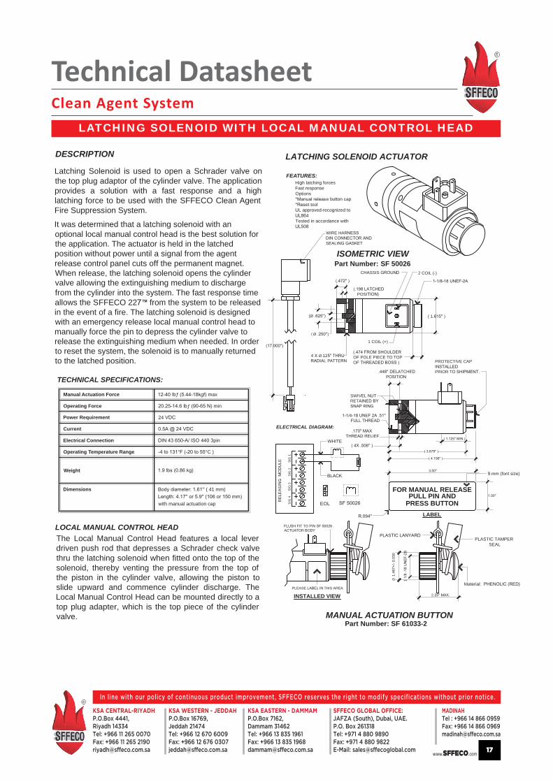
DESCRIPTION
Latching Solenoid is used to open a Schrader valve onthe top plug adaptor of the cylinder valve. The applicationprovides a solution with a fast response and a highlatching force to be used with the SFFECO Clean AgentFire Suppression System.
It was determined that a latching solenoid with anoptional local manual control head is the best solution forthe application. The actuator is held in the latchedposition without power until a signal from the agentrelease control panel cuts off the permanent magnet.When release, the latching solenoid opens the cylindervalve allowing the extinguishing medium to dischargefrom the cylinder into the system. The fast response timeallows the SFFECO 22 ™ from the system to be releasedin the event of a fire. The latching solenoid is designedwith an emergency release local manual control head tomanually force the pin to depress the cylinder valve torelease the extinguishing medium when needed. In orderto reset the system, the solenoid is to manually returnedto the latched position.
TECHNICAL SPECIFICATIONS:
Manual Actuation Force
Operating Force
Power Requirement
Current
Electrical Connection
Operating Temperature Range
Weight
lbƒ max
lbƒ min
24
° °C )
kg)
LATCHING SOLENOID ACTUATOR
MANUAL ACTUATION BUTTON
ISOMETRIC VIEW
TO TOR
PLEASE THIS AREA
INSTALLED VIEW
LABEL
t size)
Part Number: SF 61033-2
Part Number: SF 50026
FEATURES:High latching forcesFast responseOptions
e button capet tool
L approved-recognized to4
Tested in accordance with
LOCAL MANUAL CONTROL HEADThe Local Manual Control Head features a local leverdriven push rod that depresses a Schrader check valvethru the latching solenoid when fitted onto the top of thesolenoid, thereby venting the pressure from the top ofthe piston in the cylinder valve, allowing the piston toslide upward and commence cylinder discharge. TheLocal Manual Control Head can be mounted directly to atop plug adapter, which is the top piece of the cylindervalve.
Dimensions ( 41 mm) (
with manual actuation cap
FOR MANUAL RELEASEPULL PIN AND
PRESS BUTTON
Material )
PLASTIC TAMPER SEAL
PLAS
Ø1
1
2
PROTECTIVE CAPIPRIOR T
WIRE HAR
SEALI
2 COIL (-)CHASSIS
( 1.
1 COIL
(Ø
Ø.12AL PATTE
ATCHE P
POSI )
(Ø
SWIRET
R G
E
ELIEF
OF POLE PIECE TO TOPOF
REL
EASI
LE
SIG
4SI
G 2
SIG
1
EOL
ELECTRICAL DIAGRAM:
WHITE
LATCHING SOLENOID WITH LOCAL MANUAL CONTROL HEAD
Technical DatasheetClean Agent System
www.SFFECO.com
In line with our policy of continuous product improvement, SFFECO reserves the right to modify specifications without prior notice.
KSA CENTRAL-RIYADHP.O.Box 4441,Riyadh 14334Tel: +966 11 265 0070Fax: +966 11 265 [email protected]
KSA EASTERN - DAMMAMP.O.Box 7162,Dammam 31462Tel: +966 13 835 1961Fax: +966 13 835 [email protected]
KSA WESTERN - JEDDAHP.O.Box 16769,Jeddah 21474Tel: +966 12 670 6009Fax: +966 12 676 [email protected]
MADINAH Tel : +966 14 866 0959Fax: +966 14 866 [email protected]
SFFECO GLOBAL OFFICE:JAFZA (South), Dubai, UAE.P.O. Box 261318Tel: +971 4 880 9890Fax: +971 4 880 9822E-Mail: [email protected] 18
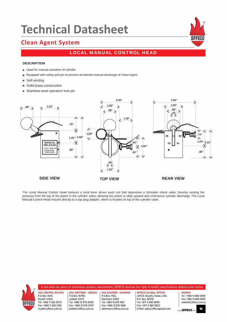
SIDE VIEW TOP VIEW REAR VIEW
DESCRIPTION
The Local Manual Control Head features a local lever driven push rod that depresses a Schrader check valve, thereby venting thepressure from the top of the piston in the cylinder valve, allowing the piston to slide upward and commence cylinder discharge. The LocalManual Control Head mounts directly to a top plug adapter, which is located on top of the cylinder valve.
for manual actuation of cylinder
d with safety pull-pin to prevent accidental manual discharge of Clean Agent
Self-ventingSolid brass constructionStainless steel operation lock pin
DOWN HARD
RELEASEMANUAL
1.PULL RING PIN2.PUSH KNOB
3.50''
1.62''.98''.25''
.72''
3.00''
1.62''
.98''
1.38''
.25''
.81''
1.62''
.81''
1.62''
1.00''
1.62''.98''
1.20'' 2.90''
.95''
.75''
2.15''
.95''
1.20''
LOCAL MANUAL CONTROL HEAD

Technical DatasheetClean Agent System
www.SFFECO.com
In line with our policy of continuous product improvement, SFFECO reserves the right to modify specifications without prior notice.
KSA CENTRAL-RIYADHP.O.Box 4441,Riyadh 14334Tel: +966 11 265 0070Fax: +966 11 265 [email protected]
KSA EASTERN - DAMMAMP.O.Box 7162,Dammam 31462Tel: +966 13 835 1961Fax: +966 13 835 [email protected]
KSA WESTERN - JEDDAHP.O.Box 16769,Jeddah 21474Tel: +966 12 670 6009Fax: +966 12 676 [email protected]
MADINAH Tel : +966 14 866 0959Fax: +966 14 866 [email protected]
SFFECO GLOBAL OFFICE:JAFZA (South), Dubai, UAE.P.O. Box 261318Tel: +971 4 880 9890Fax: +971 4 880 9822E-Mail: [email protected] 19
DESCRIPTION
High brass constructionMounts directly on top of cylinder valves
Self-venting
The Piston Actuator features a pneumatically drivenpiston that depresses a Schrader check valve,thereby venting the pressure from the top of thepiston in the cylinder valve, allowing the piston toslide upward and commence cylinder discharge. Thepneumatic pressure ired to operate the PistonActuator is obtained from the port of thecylinder, which is designated as aster cylinderthat is either mechanically a electricallyactuated. Multiple cylinders with PistonActuators can be activated from one master cylinderusing copper tubing or 1 metal flex hose. ThePiston Actuator mounts directly to a top plugadapter,which is located on top of the cylinder valve.
When using the metal Flex hose SF SF SF the
length of the flex hose is to be subtracted fromtotal length of copper tubing in the Table above-mentioned to determine the max. length ofcopper tubing that can be used. At no time maythe total length of copper tubing and the flex hoseexceed the stated length.
NOTE:
35 1'' 7 50 ft.
1''
1 1/2''
1 1/2''
2 1/2''
2 1/2''
6 30 ft.
Piston Actuator QuantitiesCylinder Size Valve Size Piston Actuator
Total Max. LengthCopper Tube
70
150
250
375
5604''1200
6
6
7
7
7
30 ft.
30 ft.
50 ft.
50 ft.
50 ft.
Pressure Supplied from Port M of MasterCylinder Valve
1.75''0.125''
3.025''
1.875''
1.056''
0.094''
SECTIONAL VIEW(Piston Actuator Control Head-Slave)
PistonAfter Operation
To return Piston afteroperation,Push on thePiston Rod.
PISTON ACTUATOR

Technical DatasheetClean Agent System
www.SFFECO.com
In line with our policy of continuous product improvement, SFFECO reserves the right to modify specifications without prior notice.
KSA CENTRAL-RIYADHP.O.Box 4441,Riyadh 14334Tel: +966 11 265 0070Fax: +966 11 265 [email protected]
KSA EASTERN - DAMMAMP.O.Box 7162,Dammam 31462Tel: +966 13 835 1961Fax: +966 13 835 [email protected]
KSA WESTERN - JEDDAHP.O.Box 16769,Jeddah 21474Tel: +966 12 670 6009Fax: +966 12 676 [email protected]
MADINAH Tel : +966 14 866 0959Fax: +966 14 866 [email protected]
SFFECO GLOBAL OFFICE:JAFZA (South), Dubai, UAE.P.O. Box 261318Tel: +971 4 880 9890Fax: +971 4 880 9822E-Mail: [email protected] 20
240 PSI PRESSURE GAUGE
FRONT VIEW SIDE VIEW
360 PSI PRESSURE GAUGE
FRONT VIEW SIDE VIEW
1 F 1
F
REC
HARG OVER CH
ARE
E
SE HFC
WITH OL
22 ea
WHITE
1.420
GRE
°
°°
° ° °
°
Ø
22 F 21
F
M
REC
HARG OVER CH
ARE
E
SE HFC
WITH OL
22 ea
1.605
GRE
WHITE
°
12°
°
°
°°
42°
12°
NOTES:
1. All Printing are no mor m center of dial.2.
e (white)Pie area (red,green,red)All printing (black)Mark (black)
lack)s ar m center (black)
4. Point - , ercharged Point - , Point - ps ,
ck)
Ø
M
NOTES:
1. All Printing are no mor m center of dial.2.
e (white)Pie area (red,green,red)All printing (black)Mark (black)
lack)s ar m center (black)
4. Font sizes (colorOver (black)
Point- e with HFC22 ea onl (black) Point- ps , ,
12°
12°
AR TAPPL TO SMO RFACES.
.440
1.420 1.230
1.055
.365
AR TAPPL TO SMO RFACES. .440
1.605 1.415
1.055
.365
Part Number: SF 27-15-18
Part Number: SF 27-15-17
ELLOW POI ER
LOW PO TER
PRESSURE GAUGES

Technical DatasheetClean Agent System
www.SFFECO.com
In line with our policy of continuous product improvement, SFFECO reserves the right to modify specifications without prior notice.
KSA CENTRAL-RIYADHP.O.Box 4441,Riyadh 14334Tel: +966 11 265 0070Fax: +966 11 265 [email protected]
KSA EASTERN - DAMMAMP.O.Box 7162,Dammam 31462Tel: +966 13 835 1961Fax: +966 13 835 [email protected]
KSA WESTERN - JEDDAHP.O.Box 16769,Jeddah 21474Tel: +966 12 670 6009Fax: +966 12 676 [email protected]
MADINAH Tel : +966 14 866 0959Fax: +966 14 866 [email protected]
SFFECO GLOBAL OFFICE:JAFZA (South), Dubai, UAE.P.O. Box 261318Tel: +971 4 880 9890Fax: +971 4 880 9822E-Mail: [email protected] 21
MANIFOLD CHECK VALVE
SF 60261
SF 60262
SF 60263
Part Number Description
Check Valve
DESCRIPTION
Check Valves are used when two or moreagent storage cylinders are manifoldedtogether with one common discharge pipingconfiguration. Their purpose is to prevent theloss of agent in the event that any of the agentstorage cylinders are not connected to themanifold at time of system discharge and toprevent back flow of agent into other cylindersattached to the manifold.All components of the Check Valves areconstructed from brass for durability andprotection against corrosion. The metal tometal sealing area of the disc and seat isprecision lapped, providing a very tight shut-offof both gas a uid.
Check Valve
Check Valve
Valve Size
1''
1 1/2''
2 1/2''
NOTE:
The 1 and 21 2 Check Valves mustbe installed in thevertical position onlywith check disc on top.
Pipe Threads
2 eck Valve (S
SECTIONAL VIEW
1 eck Valve (S
1 ck Valve (SF
TOP VIEWTOP VIEW
TOP VIEW FRONT VIEWFRONT VIEW
PT
T
T
1 PT
SIDE VIEW
4 ck Valve (SF
TOP VIEW
SF 60264 Check Valve 4''

Technical DatasheetClean Agent System
www.SFFECO.com
In line with our policy of continuous product improvement, SFFECO reserves the right to modify specifications without prior notice.
KSA CENTRAL-RIYADHP.O.Box 4441,Riyadh 14334Tel: +966 11 265 0070Fax: +966 11 265 [email protected]
KSA EASTERN - DAMMAMP.O.Box 7162,Dammam 31462Tel: +966 13 835 1961Fax: +966 13 835 [email protected]
KSA WESTERN - JEDDAHP.O.Box 16769,Jeddah 21474Tel: +966 12 670 6009Fax: +966 12 676 [email protected]
MADINAH Tel : +966 14 866 0959Fax: +966 14 866 [email protected]
SFFECO GLOBAL OFFICE:JAFZA (South), Dubai, UAE.P.O. Box 261318Tel: +971 4 880 9890Fax: +971 4 880 9822E-Mail: [email protected] 22
SHUTTLE CHECK VALVE 1” & 1.5”
SF 50123
SF 60619
Part Number Description
Shuttle Check Valve 1''
DESCRIPTION
The brass shuttle valve is used to connect twocylinders to a common discharge pipe andnozzle(s). All threads are available with or
The purpose of having a reservesupply is that after the first cylinder (main) isdischarged, the second cylinder (reserve) canbe manually transferred via serveswitch to restore fire fighting readiness.
The shuttle valve contains a shuttle check thatcloses off the piping to the first cylinder (main)when empty. When the second cylinder isdischarged, the shuttle check prevents thecharge of the second cylinder into the firstempty cylinder (main) connected on the samemanifold, thus reducing unnecessary CleanAgent loss.
Shuttle Valve 1 Partwith Model SF r Mo
1 1/2'' NPT Outlet Path to Nozzles
Shuttle Valve (Part ) for use with Model SF E or M
Shuttle Check Valve 1 1/2''
ISOMETRIC VIEW: Shuttle Check Valve 1 1/2''
1'' NPT Outlet Path to Nozzles
From Cylinder Outlet 1'' NPT
From Cylinder Outlet 1'' NPT
From Cylinder Outlet 1'' NPT
From Cylinder Outlet 1'' NPT
6 1/4 inch
3 1/4 inch2 3/8 inch
6 inch

Technical DatasheetClean Agent System
www.SFFECO.com
In line with our policy of continuous product improvement, SFFECO reserves the right to modify specifications without prior notice.
KSA CENTRAL-RIYADHP.O.Box 4441,Riyadh 14334Tel: +966 11 265 0070Fax: +966 11 265 [email protected]
KSA EASTERN - DAMMAMP.O.Box 7162,Dammam 31462Tel: +966 13 835 1961Fax: +966 13 835 [email protected]
KSA WESTERN - JEDDAHP.O.Box 16769,Jeddah 21474Tel: +966 12 670 6009Fax: +966 12 676 [email protected]
MADINAH Tel : +966 14 866 0959Fax: +966 14 866 [email protected]
SFFECO GLOBAL OFFICE:JAFZA (South), Dubai, UAE.P.O. Box 261318Tel: +971 4 880 9890Fax: +971 4 880 9822E-Mail: [email protected] 23
DESCRIPTION
The Flex hoses are used to connect the agent storage containers to the manifold in multiple cylinders arrangement. Flexhoses are constructed of high pressure hydraulic rubber in the and sizes and stainless steel corrugated inner corewith stainless steel braided in the 2-1 size. All sizes are fitted with mal T thread on both ends.There are two options available for the lb. cylinder. They are a flex hose alone and flex hose check valve assembly.The flex hose alone is in diameter (Part SF ) and in length. The combination of flex hose and check valve,which has a diameter of (Part SF 1) and a length of , is used when using a manifold in a piping network. Allare manufactured from a stainless steel corrugated inner core with stainless steel braided. The flex hose has Victaulicfittings on both ends.
TOP VIEWSIDE VIEW
4.0''
30-1/2''
3.0'' 24.0'' 3.0''4.0''
4.0''
4" Victaulic Pipe
4.0" Victaulic Pipe
SIDE VIEW
4.0''
TOP VIEW
4.0''
4.0''
4.0" Victaulic Pipe
SF 91230
LF 91231
26-1/2''
Hose (Stainless Steel Braided)
2 1/2'' Male NPT for Connection to Cylinder Valve
Male NPT for Connection to Cylinder Valve
Male NPT for Connection toCheck Valve or System Pipe
Hose ( Rubber )
A
B MATERIALPART NO. PART NO. B MATERIAL
1 R
PART NO. B MATERIAL
2 STEEL
B
A A A
Part Number Length Diameter MaterialDescription
Flex Hose Stainless Steel ided
1 Flex Hose Check Stainless Steel aided
6''
6''
6" Victaulic Pipe
TOP VIEW
FLEXIBLE HOSES

Technical DatasheetClean Agent System
www.SFFECO.com
In line with our policy of continuous product improvement, SFFECO reserves the right to modify specifications without prior notice.
KSA CENTRAL-RIYADHP.O.Box 4441,Riyadh 14334Tel: +966 11 265 0070Fax: +966 11 265 [email protected]
KSA EASTERN - DAMMAMP.O.Box 7162,Dammam 31462Tel: +966 13 835 1961Fax: +966 13 835 [email protected]
KSA WESTERN - JEDDAHP.O.Box 16769,Jeddah 21474Tel: +966 12 670 6009Fax: +966 12 676 [email protected]
MADINAH Tel : +966 14 866 0959Fax: +966 14 866 [email protected]
SFFECO GLOBAL OFFICE:JAFZA (South), Dubai, UAE.P.O. Box 261318Tel: +971 4 880 9890Fax: +971 4 880 9822E-Mail: [email protected] 24
DESCRIPTION
The Level Indicator is a simple, manually operated device, which provides a means to determine the CleanAgent level in vertically mounted agent storage containers. Once the level is determined, it can then beconverted into the weight of Clean Agent present in the agent storage container .
OPERATIONA magnet e float moves with the level along the unit stem. Level readoutis obtained by simply removing the protective cap and pulling out a calibrated tape untilmagnetic interlock with the float is felt. With the tape in this position, the reading isobtained at the point where the tape emerges from the unit housing.
When the is determined, the reading is then referred to a chart in theEngineering Manual and the corresponding weight of Clean Agent is determined.Accurate readings can be obtained over a temperature range.
FEATURES
Reduced Maintenance Time - Weight in an agent storage containercan be determined in a fraction of the time it would take to remove andweigh them.
Part Number
Continuous Fire Protection - of the level indicator does notire taking out the cylinder from the system, thus providing
uninterrupted fire protection.Field Installation Capability - The indicator can easily be installed inthe field using a single wrench as long as the container is empty and ise with a mounting boss.
SF 60020
SF 60020-1
SF 60020-2
Part Number Description
Liquid Level Indicator for 150 LB & 250 Cylinders
Liquid Level Indicator for 375 LB & 560 Cylinders
Liquid Level Indicator for 1200 LB Cylinders
A B C D
26'' 3''1 1/2''29''
1 1/2''
1 1/2''
3''
3''
40''
40'' 43''
43'' FRONT VIEW
TOP VIEW
C
A B
2.0''
Tube
Float
C
C
D
Availability - s are available for all SFFECO containers from sizes of
Flexibility - The flexible tape design allows the unit to be used in tight spaces that would otherwise hinder the use of a rigid type indicato
Compact - When not in use, the uires no more space than that container.
LIQUID LEVEL INDICATOR (OPTIONAL)
Technical DatasheetClean Agent System
www.SFFECO.com
In line with our policy of continuous product improvement, SFFECO reserves the right to modify specifications without prior notice.
KSA CENTRAL-RIYADHP.O.Box 4441,Riyadh 14334Tel: +966 11 265 0070Fax: +966 11 265 [email protected]
KSA EASTERN - DAMMAMP.O.Box 7162,Dammam 31462Tel: +966 13 835 1961Fax: +966 13 835 [email protected]
KSA WESTERN - JEDDAHP.O.Box 16769,Jeddah 21474Tel: +966 12 670 6009Fax: +966 12 676 [email protected]
MADINAH Tel : +966 14 866 0959Fax: +966 14 866 [email protected]
SFFECO GLOBAL OFFICE:JAFZA (South), Dubai, UAE.P.O. Box 261318Tel: +971 4 880 9890Fax: +971 4 880 9822E-Mail: [email protected] 25
Discharge Nozzle
SF 60704-2
SF 60704-3
SF 60705-2
SF 60705-3
SF 60706-2
SF 60706-3
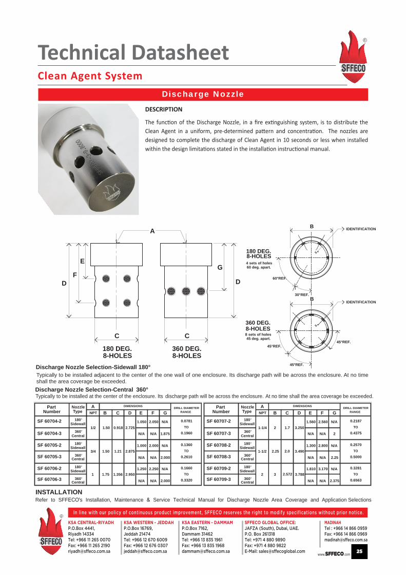
Discharge Nozzle Selection-Sidewall 180°Typically to be installed acent to the center of the one wall of one enclosure. Its discharge path will be across the enclosure. At no timeshall the area coverage be exceeded.
Typically to be installed at the center of the enclosure. Its discharge path will be across the enclosure. At no time shall the area coverage be exceeded.
INSTALLATIONRefer to SFF s Installation, Maintenance Service Technical Manual for charge zle Area Coverage and Application Selections
Discharge Nozzle Selection-Central 360°
NumberA Part
TypeNozzle
B C D E F GNPT RANGEDRILL DIAMETERDIMENSIONS
SF 60707-2
SF 60707-3
SF 60708-2
SF 60708-3
SF 60709-2
SF 60709-3
NumberAPart
TypeNozzle
B C D E F GNPT RANGEDRILL DIAMETERDIMENSIONS
180°
360°1/2
3/4
1
1.50
1.50
1.75
0.918
1.21
1.356
2.725
2.875
2.950
N/A 1.875N/A
N/A1.050 2.050
N/A 2.000N/A
N/A1.000 2.000
N/A 2.000N/A
N/A1.250 2.250
0.0781
0.1960TO
0.1360
0.2610TO
0.1660
0.3320TO
1-1/4
1-1/2
2
2
2.25
3
1.7
2.0
2.572
3.250
3.490
3.788
N/A 2N/A
N/A1.560 2.560
N/A 2.25N/A
N/A1.300 2.800
N/A 2.375N/A
N/A1.810 3.170
0.2187
0.4375TO
0.2570
0.5000TO
0.3281
0.6563TO
S
IDENTIFICATION
180 DEG.
60°REF.
30°REF.
45°REF.
S
45°REF.
IDENTIFICATION
45°REF.
D
E
F
C
8-HOLES360 DEG.8-HOLES
C
G
D
A
180 DEG.8-HOLES
360 DEG.8-HOLES
B
B
4 sets of holes60 deg. apart.
8 sets of holes45 deg. apart.
Sidewall
Central
180°
360°
Sidewall
180°
360°
Sidewall
Central
Central
180°
360°
Sidewall
Central
180°
360°
Sidewall
180°
360°
Sidewall
Central
Central
DESCRIPTION
The function of the Discharge Nozzle, in a fire extinguishing system, is to distribute the Clean Agent in a uniform, pre-determined pattern and concentration. The nozzles are designed to complete the discharge of Clean Agent in 10 seconds or less when installed within the design limitations stated in the installation instructional manual.

Technical DatasheetClean Agent System
www.SFFECO.com
In line with our policy of continuous product improvement, SFFECO reserves the right to modify specifications without prior notice.
KSA CENTRAL-RIYADHP.O.Box 4441,Riyadh 14334Tel: +966 11 265 0070Fax: +966 11 265 [email protected]
KSA EASTERN - DAMMAMP.O.Box 7162,Dammam 31462Tel: +966 13 835 1961Fax: +966 13 835 [email protected]
KSA WESTERN - JEDDAHP.O.Box 16769,Jeddah 21474Tel: +966 12 670 6009Fax: +966 12 676 [email protected]
MADINAH Tel : +966 14 866 0959Fax: +966 14 866 [email protected]
SFFECO GLOBAL OFFICE:JAFZA (South), Dubai, UAE.P.O. Box 261318Tel: +971 4 880 9890Fax: +971 4 880 9822E-Mail: [email protected] 26
DISCHARGE PRESSURE SWITCH
PRESSURE SUPERVISORY SWITCH
Characteristics:0.125 – 27 NPT male thread 58± psig actuation pressure40± psig release pressureTemperature -65°F 250 proof pressure 5,000 burst pressure Contacts –Silver – 20 amps 120VAC / 240 VAC DPS 10 -370 Normally open – Normally closed,
Normally Open : RedNormally Closed : BlackCommon : White
TO BE INSTALLED INTO PORT ‘M’
Upon activation of the cylinder valve, the operation pressure switches contacts transfer to indicate discharge or to perform disconnect/activation required during system operation.
BLUEPURPLEBLACKTO BE INSTALLED INTO PORT ‘P’
Characteristics:0.125 – 27 NPT male thread 430 ± 10 psig actuation pressureTemperature -65°F to 275°F 600 psig proof pressure 5,000 burst pressureContacts – Silver 2AMP 28VDC 375 VA 120 VAC Pilot DutyNormally open – Normally closed,
Normally Open : BlueNormally Closed : BlackCommon : Violet
The Pressure Supervisory Switch is normally wired into a supervisory circuit to give a trouble signal upon activation
Technical DatasheetClean Agent System
www.SFFECO.com
In line with our policy of continuous product improvement, SFFECO reserves the right to modify specifications without prior notice.
KSA CENTRAL-RIYADHP.O.Box 4441,Riyadh 14334Tel: +966 11 265 0070Fax: +966 11 265 [email protected]
KSA EASTERN - DAMMAMP.O.Box 7162,Dammam 31462Tel: +966 13 835 1961Fax: +966 13 835 [email protected]
KSA WESTERN - JEDDAHP.O.Box 16769,Jeddah 21474Tel: +966 12 670 6009Fax: +966 12 676 [email protected]
MADINAH Tel : +966 14 866 0959Fax: +966 14 866 [email protected]
SFFECO GLOBAL OFFICE:JAFZA (South), Dubai, UAE.P.O. Box 261318Tel: +971 4 880 9890Fax: +971 4 880 9822E-Mail: [email protected] 27
WARNING SIGNS
SFFECOHFC227ea GAS
SFFECOHFC227ea GAS
SFFECOHFC227ea GAS
SFFECOHFC227ea GAS
SYSTEM ABORT
SFFECOHFC227ea GAS
FLASHING LIGHT
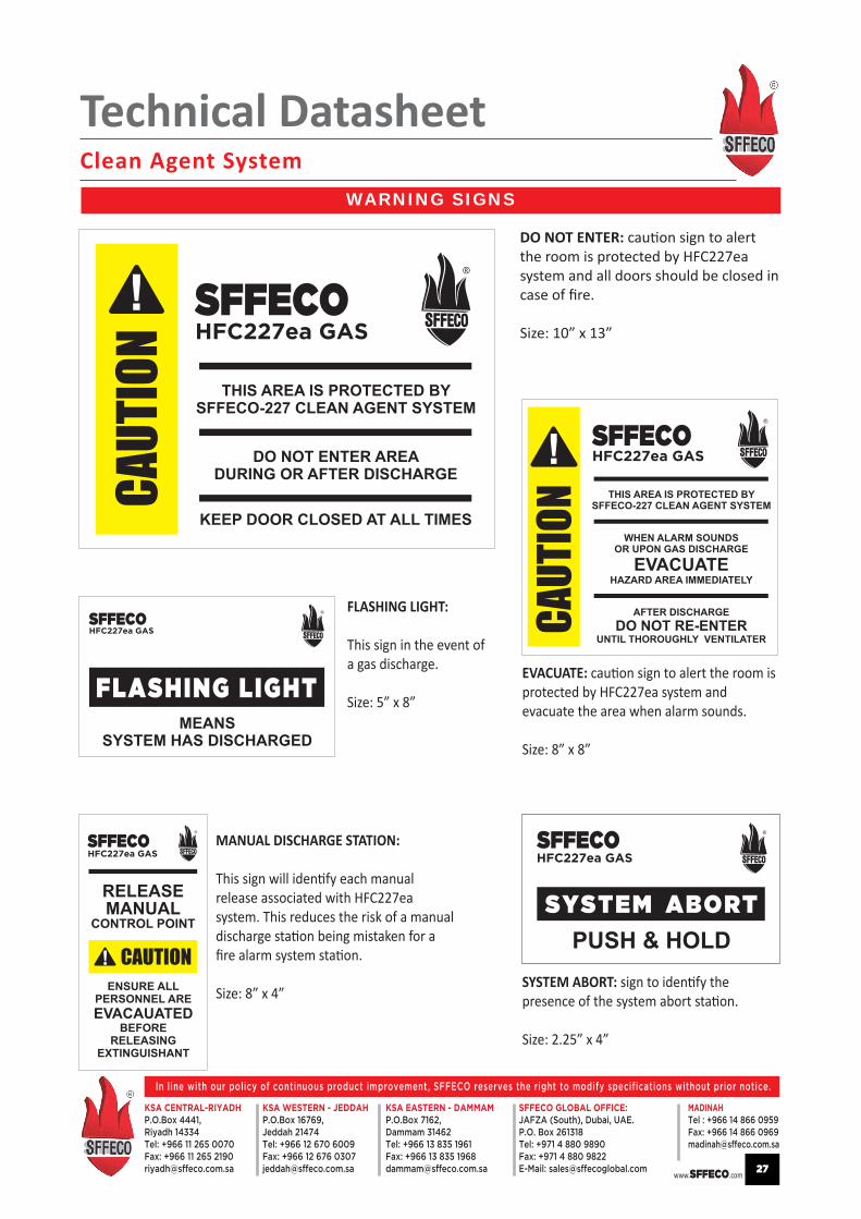
DO NOT ENTER: caution sign to alert the room is protected by HFC227ea system and all doors should be closed in case of fire.
Size: 10” x 13”
EVACUATE: caution sign to alert the room is protected by HFC227ea system and evacuate the area when alarm sounds.
Size: 8” x 8”
MANUAL DISCHARGE STATION:
This sign will identify each manual release associated with HFC227ea system. This reduces the risk of a manual discharge station being mistaken for a fire alarm system station.
Size: 8” x 4”
FLASHING LIGHT:
This sign in the event of a gas discharge.
Size: 5” x 8”
SYSTEM ABORT: sign to identify the presence of the system abort station.
Size: 2.25” x 4”


