SR200-HFC227ea GAS SUPPRESSION SYSTEM...
91
SR200-HFC227ea Engineering Manual SRI Issued Sept 24, 2010, Rev: 05 SR200-HFC227ea GAS SUPPRESSION SYSTEM ENGINEERING MANUAL
Transcript of SR200-HFC227ea GAS SUPPRESSION SYSTEM...

SR200-HFC227ea Engineering Manual
SRI Issued Sept 24, 2010, Rev: 05
SR200-HFC227ea GAS SUPPRESSION SYSTEM
ENGINEERING MANUAL
SR200-HFC227ea Engineering Manual
SRi Issued Sept 24, 2010, Rev: 05 - i -
SR200-HFC227ea GAS FIRE SUPPRESSION SYSTEM
ENGINEERING MANUAL
CONTENTS
1. General Information Page
1.1 Philosophy Statement 1
1.2 Proprietary Notice
1.3 Distribution of Manual
1.4 Warranty Policies
2. System Design
2.1 General 2
2.2 Evaluation of Hazard / Risks 2
2.3 Planning 3
2.4 Specifications & Physical Properties of HFC-227ea gas 5
2.5 Design Flow Chart 6
2.6 Defining the hazard 7
2.7 Determine the hazard volume 7
2.8 Determine the agent required 7
2.9 Atmospheric Correction Factors 10
2.10 Determine the cylinder size required 11
2.11 Determine the nozzle quantity & locations 12
2.12 Distribution piping requirements 13
2.13 Calculate the quantity of agent thru nozzle 14
2.14 Layout of Cylinders and Manifold 15
2.15 Computer Calculations - VdS Program 15
2.16 Preparation of Contract Drawings 15
2.17 Leakage/Venting Consideration 16
2.18 Extended discharge 16
3. Drawings and Component Data
3.1 General 17
3.2 Equipment Data Sheet 001-018 19-42
4. Computer Calculation-VdS Program
4.1 General 43
5. Installation Instructions
5.1 General 44
5.2 Safety 44
5.3 Recommended Tools for system installation 45
5.4 Installation Procedures 45

SR200-HFC227ea Engineering Manual
SRi Issued Sept 24, 2010, Rev: 05 - ii -
SR200-HFC227ea GAS FIRE SUPPRESSION SYSTEM
ENGINEERING MANUAL
CONTENTS
6. Testing and Commissioning Instructions Page
6.1 Pre-commissioning Check List 57
6.2 Commissioning Procedures 57
6.3 Commissioning Forms 58
7. Operation and Maintenance Manual
7.1 General 64
7.2 Safety Notices 64
7.3 Operation of the System 64
7.4 After A Fire / System Discharged 65
7.5 Maintenance of the System 65
7.6 Inspection of the System 68
7.7 Inspection and Maintenance Checklist 69
8. Filling of HFC-227ea
8.1 General 74
8.2 Specifications for HFC-227ea 74
8.3 Installation of SR200 Valve 75
8.4 Filling Methods 76
8.5 Cylinder Maintenance 77
8.6 Filling Checklist 78
8.7 Filling List 80
9. Safety Instructions
9.1 General 82
10. Detection and Control
10.1 General 84
10.2 Detection Speed 84
10.3 Types of Detectors 84
10.4 Detector Spacing 85
10.5 Detector Location 85
10.6 Typical Sequence 85
A. Appendix A - Component Drawings
i. High Pressure Hoses
ii. Check Valve
iii. Discharge Nozzle
iv. Valve Outlet Adaptor
v. Cylinder Mounting System
vi. Pressure Gauge

SR200-HFC227ea Engineering Manual
SRi Issued Sept 24, 2010, Rev: 05 - iii -
CONTENTS
vii. Syphon Tubes
B. Appendix B – Supply confirmation
i. Supply confirmation of Ceodeux for Pressure Gauge “PGS 21.050”

SR200-HFC227ea Engineering Manual
SRI Issued Sept 24, 2010, Rev: 05 Sec.1 - 1 -
SR200-HFC227ea GAS FIRE SUPPRESSION SYSTEM
ENGINEERING MANUAL
1. GENERAL INFORMATION
1.1 PHILOSOPHY STATEMENT
The philosophy at Steel Recon Industries Sdn. Bhd (SRI) is to save our clients and customers
valuable time and money by providing them with reliable and unparallel “one stop” fire
protection solutions at reasonable prices. Our mission is to provide a fire safe environment for
everyone, our vision is to become a leader in world class fire-fighting products and our
corporate culture of “Nothing is constant...the only constant is continuous improvement”
attitude will ensure that SRI will continue to “Lead the fight against fire”.
1.2 PROPRIETARY NOTICE
The SR200-HFC227ea gas system manual is a proprietary data of SRI. Reproduction of the
whole or any part of this manual other than the support of the equipment for which is published
is not allowed without the permission in writing by SRI.
1.3 DISTRIBUTION OF MANUAL
This manual is distributed only to persons/companies listed on SRI distributor list. The content
of this manual are CONFIDENTIAL and is not to be distributed to any third parties without the
written consent from SRI. The manual shall always be returned to SRI in the event that the
persons/companies distribution rights is terminated and/or cancelled by either party.
This manual does not cover the detection and control system and must be designed according
to local requirements.
1.4 WARRANTY POLICIES
The components of the Halocarbon gas suppression system supplied by SRI are warranted to
the original purchaser for 1 (one) year from the date of order against defects in workmanship
and material. SRI will replace or repair any SRI supplied components which, in its opinion are
defective and have not been tampered with or subjected to misuse, abuse or exposed to highly
corrosive conditions provided that written notice of the alleged defect shall be given to SRI
within 30 days after discovery thereof, and prior to the expiration of one year after order, and
further provided that is SRI so instructs, such article or part thereof is promptly returned to SRI
with shipping charges pre-paid.

SR200-HFC227ea Engineering Manual
SRI Issued Sept 24, 2010, Rev: 05 Sec.2 - 2 -
SR200-HFC227ea GAS FIRE SUPPRESSION SYSTEM
ENGINEERING MANUAL
2. SYSTEM DESIGN 2.1 GENERAL The SR 200-HFC227ea Gas Fire Suppression system utilizes the halocarbon gas Heptafluoropropane
(HFC-227ea ) in NFPA 2001 and ISO 14520-1. The general requirements and design criteria are based
on both NFPA 2001 and ISO 14520-1. The SR200-HFC227ea gas fire suppression system is
employed as a total flooding system and should not be used for local application system. HFC-227ea
suppresses fire by absorbing heat energy at its molecular level faster than the heat can be generated, so
the fire cannot sustain itself. It also forms free radicals to chemically interfere with the chain reaction
of the combustion process. This makes it a highly effective fire fighting agent that is safe for people
and causes no damage to equipment.
2.2 EVALUATION OF HAZARD / RISK As a general rule, all fire protection systems begin with a risk assessment which should evaluate the
following:-
1. the consequences of material loss or interruption of services
2. what combustible materials are present
3. possible sources of ignition either internally or externally
4. evacuation of the area
5. consequences of fire spread to adjoining areas
6. whether the hazard area is or can be enclosed
This process will clarify whether an active fire protection system is required, how fast it must respond
and whether a gas extinguishing is suitable and practical.
In the design of a SR200-HFC227ea Gas Fire Suppression system, it is important to correctly define
the hazard and conduct a thorough survey to determine if the halocarbon gas system will properly
protect the enclosure / hazards.
The SR200-HFC227ea Gas Suppression system is effective to suppress the following types of fires :-
Class A - Surface Fires / Ordinary Combustible Fires
Fires which involves ordinary combustibles such as wood, paper, fabric, etc.
Class B - Flammable Liquid Fires
Fires which involves liquid hydrocarbons or polar solvents.
Class C - Flammable Gas Fires
Fires which involves gaseous hydrocarbons or polar solvents.
Class E - Energized Electrical Equipment Fires
These fires may include computer rooms, control rooms, transformers, oil switches, circuit breakers,
rotating equipment, pumps and motors.

SR200-HFC227ea Engineering Manual
SRI Issued Sept 24, 2010, Rev: 05 Sec.2 - 3 -
The halocarbon Gas Suppression system is NOT effective on the following types of fires :-
Class D - Combustible Metals
Reactive metals such as lithium, sodium, potassium, magnesium, titanium, zirconium, uranium &
plutonium.
Certain chemicals or mixture of chemicals such as cellulose nitrate and gunpowder, that is capable of
rapid oxidation in the absence of air.
OR
Chemicals capable of undergoing auto thermal decomposition, such as certain organic peroxides and
hydrazine
OR
Metal hydrides.
2.3 PLANNING In the design of a SR200-HFC227ea Gas Fire Suppression system, it is important to correctly define
the hazard and conduct a thorough survey to determine if the halocarbon gas system will properly
protect the enclosure / hazards. The halocarbon gas system should be used with an automatic early fire
detection system to prevent a deep seated fire from developing as a result of a long pre-burn time.
2.3.1 Type of Hazards Briefly describe the types of hazards being protected. Record anything unique or unusual about the
hazard.
2.3.2 Hazard / Enclosure Integrity Survey An integrity test is recommended to determine the natural venting area and the agent retention
prediction for the enclosure. One method is by a door fan test. For more information refer to
NFPA2001 -Standard for Clean Agent Fire Extinguishing Systems Annex C as well as ISO 14520
Annex E.
2.3.3 Hazard / Enclosure Atmosphere
If the hazard / enclosure is designated as explosion-proof, the control system, releasing devices,
electric valve actuators, pressure switches and pressure monitoring switches (if not approved for
hazardous environments) must be located away from the hazard area and the system must be remotely
piped to the area. Only the detectors, distribution piping, nozzles or other non-electrical parts may be
located in the hazard, alternatively explosion-proof components must be used.
2.3.4 Hazard Ventilation Considerations All electrical power sources associated with the protected hazard should be shutdown prior to system
discharge to eliminate the possibility of a fire being electrically reignited.

SR200-HFC227ea Engineering Manual
SRI Issued Sept 24, 2010, Rev: 05 Sec.2 - 4 -
2.3.5 Temperature Range Considerations For the hazard area determine the design temperature as well as the maximum ambient temperature.
The agent required is based on the expected design ambient temperature in the hazard area. If the
difference in the lowest and the highest expected ambient temperature is significant, it may be more
appropriate to calculate the concentration level at a median expected ambient temperature to ensure
that it does not exceed the NOAEL value for the agent as stated in NFPA2001 and ISO 14250 during
the highest expected temperature whilst having a sufficient extinguishing concentration during the
lowest expected temperature. The agent cylinder must be located indoors in an area with a temperature
range from 0oC to 50oC.
2.3.6 Volume Reduction In the calculation of the volume of the hazard, it is normally considered to be empty. However, if there
are fixed, non-moveable objects such as beams, columns and permanent dividers in the hazard area,
their volumes shall be deducted from the total hazard volume.
2.3.7 Reserve System If a reserve system is required, determine if it should be permanently connected or stored on the
premises. Generally, a reserve system is recommended if the hazard is located in a remote area where
there are difficulties in recharging the cylinders within a reasonable time or the system is protecting a
high risk / value hazard. The addition of a reserve system will invariably add to the job cost estimate.
2.3.8 Cylinders and Accessories Location In selection a suitable location that is acceptable with the end-user, the following guidelines must
apply:-
1. The temperature range is within the limits
2. Piping limitation are not exceeded
3. The components are not subjected to damage or vandalism
4. A manual release system is installed and accessible
5. Cylinders and actuation devices must be stored in a weatherproof area
6. If cylinders are stored in a dedicated area, ensure that the area is not used for storage of
other equipment which may add a fire risk to the room.
7. The location should be a dry area, and should not be subjected to a corrosive environment.
2.3.9 Discharge Test Generally a discharge test is not recommended due to the costs involved as well as the environmental
impact of the gas.
2.3.10 Authority Having Jurisdiction Contact the end-user or the local authority having jurisdiction to establish the requirements for the
following :-
1. Detector spacing requirements
2. Type of detection and control system that is acceptable
3. Audio and visual alarms requirements
4. Inspection of equipment
5. If reserve system is required

SR200-HFC227ea Engineering Manual
SRI Issued Sept 24, 2010, Rev: 05 Sec.2 - 5 -
2.4 SPECIFICATIONS AND PHYSICAL PROPERTIES OF HFC-227ea GAS. 2.4.1 Physical Properties of Halocarbon Agent HFC-227ea in NFPA 2001
Halocarbon agent HFC-227ea is known as Heptafluoropropane and its chemical formula is
CF3CHFCF3
Properties Value Units
Molecular Weight 170 -
Boiling Point @ 1.013 bar (absolute) -16.4 oC
Freezing Point -131 oC
Critical Temperature 101.7 oC
Critical Pressure 29 Bar
Critical Volume 274 cc/mole
Critical Density 621 kg/m3
Specific heat, liquid @ 25oC 1.184 kJ/kg oC
Specific heat, vapour @ constant
pressure (1 atm) and 25oC 0.808 kJ/kg oC
Heat of Vaporization at boiling point 132.6 kJ/kg
Thermal conductivity of liquid @ 25 oC 0.069 W/m oC
Viscosity, liquid at 25oC 0.184 centipoise
Relative dielectric strength at 1 atm at
734 mm Hg, 25oC (N2 = 1.0) 2 -
Solubility of water in agent 0.06% by weight ppm

SR200-HFC227ea Engineering Manual
SRI Issued Sept 24, 2010, Rev: 05 Sec.2 - 6 -
2.5 DESIGN FLOW CHART
Determine hazard material and required design concentration
↓
Identify individual enclosure volumes and deduct any impermeable volumes where appropriate. Calculate the hazard volume in m3
↓
Determine the hazard altitude and correction factor
↓
Calculate agent quantity required per enclosure, at minimum design temperature expected at enclosure
↓
Determine the size of cylinder needed and if necessary the no. of cylinders required
↓
Select the nozzle type and determine location(s)
↓
Determine the location of the cylinder(s) to define the manifold layout (if multiple cylinders are used) and the distribution piping. Estimate the required pipe sizes
↓
Calculate quantity of agent per nozzle and check percentage agent split at Tee’s
↓
Identify all pipe lengths, rises, falls and nozzle reference numbers. Draw the isometric layout of pipe and node system
↓
Run the computer calculation for pipe sizing, nozzle sizes and orifice sizes, the predicted agent concentration and the predicted discharge times.
↓
Prepare contract drawings
↓
Determine the leakage / venting consideration

SR200-HFC227ea Engineering Manual
SRI Issued Sept 24, 2010, Rev: 05 Sec.2 - 7 -
2.6 DEFINING THE HAZARD Defining the hazard shall include the following steps:-
1. Determine the fuel(s) within the risk which would propagate a fire once started. The fuel
with the highest required agent concentration to govern.
2. Determine the closable and unclosable openings within the hazard enclosure which may
affect the performance of the halocarbon gas system.
3. Determine whether the halocarbon gas system is to be used for extinguishing or inerting
purposes within the risk.
4. Determine the design temperature of the hazard enclosure.
5. Select the flooding factor / design concentration required for the risk. For the required
agent flooding factor / design concentration requirement see tables 2.8-1 and 2 with the
appropriate temperature.
6. All floor voids shall be included in the protection. All ceiling voids over 800mm should be
included in the protection. Ceiling voids less than 800mm may require protection: a) if a
hazard exists within them, b) if there are unclosable openings into the main hazard, c) if the
void forms part of the ventilation system.
2.7 DETERMINE THE HAZARD VOLUME The hazard enclosure volume needs to be determined in order to calculate the amount of agent
required and the number of cylinders used. Calculate the volume using the internal dimensions of the
enclosure in meters.
If the enclosure has solid immovable objects such as beams and columns, their volumes must be
deducted to determine the nett hazard volume.
2.8 DETERMINE THE AGENT REQUIRED In determining the amount of agent required the following design concentrations (as specified in
NFPA 2001: 2008 edition*) are used:-
Agent Class A Design Concentration Class B Design
HFC-227ea 6.25 – 7% 8.7%
Note (1): The design temperature is at 21oC (70oF). The class B value is for heptane.
* NFPA 2001: 2008 edition – Table A.5.4.2.2 (b)
Agent No Observable Adverse Effects
Level (NOAEL) concentration
Lowest Observable Adverse
Effects Level (LOAEL)
concentration
HFC-227ea 9% 10%
Note: System designers must be aware of the NOAEL and LOAEL values for HFC-227ea when
designing the system for normally occupied areas.
Refer to tables 2.8-1(SI units) or 2.8-2(US units) to select the required flooding factor for the required
minimum design concentration at the design temperature of the hazard enclosure. The table shows the
flooding factor based on the weight of gas to the volume of the hazard.
Alternatively, the amount of agent required can be calculated using the formulas as stated below the
table. The formula is useful for calculating the amount of agent required for other design
concentrations as well as for different temperatures not stated in the table.

SR200-HFC227ea Engineering Manual
SRI Issued Sept 24, 2010, Rev: 05 Sec.2 - 8 -
Table 2.8-1 HFC-227ea total flooding quantity (SI Units)
Temp Specific Weight Requirements of Hazard volume, W/V (kg/m3)
Vapour
Volume Design concentration (% per volume)
(t) (s)
oC m3/kg 6% 7% 8% 9% 10% 11% 12% 13%
-10 0.1215 0.5254 0.6196 0.7158 0.8142 0.9147 1.0174 1.1225 1.2301
-5 0.1241 0.5142 0.6064 0.7005 0.7987 0.8951 0.9957 1.0985 1.2038
0 0.1268 0.5034 0.5936 0.6858 0.7800 0.8763 0.9748 1.0755 1.1785
5 0.1294 0.4932 0.5816 0.6719 0.7642 0.8586 0.9550 1.0537 1.1546
10 0.1320 0.4834 0.5700 0.6585 0.7490 0.8414 0.9360 1.0327 1.1316
15 0.1347 0.4740 0.5589 0.6457 0.7344 0.8251 0.9178 1.0126 1.1096
20 0.1373 0.4650 0.5483 0.6335 0.7205 0.8094 0.9004 0.9934 1.1859
25 0.1399 0.4564 0.5382 0.6217 0.7071 0.7944 0.8837 0.9750 1.0684
30 0.1425 0.4481 0.5284 0.6104 0.6943 0.7800 0.8676 0.9537 1.049
35 0.1450 0.4401 0.519 0.5996 0.6819 0.7661 0.8522 0.9402 1.0303
40 0.1476 0.4324 0.5099 0.5891 0.6701 0.7528 0.8374 0.9230 1.0124
45 0.1502 0.4250 0.5012 0.579 0.6586 0.7399 0.8230 0.9080 0.9950
50 0.1527 0.418 0.4929 0.5694 0.6476 0.7276 0.8093 0.8929 0.9784
55 0.1553 0.4111 0.4847 0.56 0.6369 0.7156 0.796 0.8782 0.9623
Symbols:
W/V is the agent weight requirements (kg/m3); i.e. the quantity Q (kg) of agent required at a
temperature of 20oC and a pressure of 1.013 bar per cubic meter of protected volume to produce the
indicated concentration at the temperature specified:
Q = V
C
S 100 - C
where:
V is the nett volume of hazard (m3);
S is the specific volume of superheated HFC-227ea (m3/kg)
the specific volume of superheated HFC-227ea vapour can be approximated by the formula:
S = 0.1269 + 0.0005 t
Where t = temperature (oC)
C is the concentration (%); i.e. the volumetric concentration of HFC-227ea in air at the
temperature indicated.
*Source - NFPA2001:2008 - Annex A, Table A.5.51(j)
SR200-HFC227ea Engineering Manual
SRI Issued Sept 24, 2010, Rev: 05 Sec.2 - 9 -
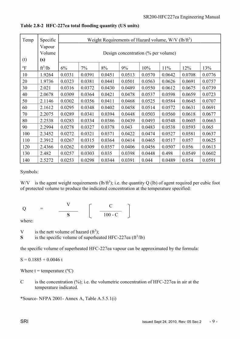
Table 2.8-2 HFC-227ea total flooding quantity (US units)
Temp Specific Weight Requirements of Hazard volume, W/V (lb/ft3)
Vapour
Volume Design concentration (% per volume)
(t) (s)
oF ft3/lb 6% 7% 8% 9% 10% 11% 12% 13%
10 1.9264 0.0331 0.0391 0.0451 0.0513 0.0570 0.0642 0.0708 0.0776
20 1.9736 0.0323 0.0381 0.0441 0.0501 0.0563 0.0626 0.0691 0.0757
30 2.021 0.0316 0.0372 0.0430 0.0489 0.0550 0.0612 0.0675 0.0739
40 2.0678 0.0309 0.0364 0.0421 0.0478 0.0537 0.0598 0.0659 0.0723
50 2.1146 0.0302 0.0356 0.0411 0.0468 0.0525 0.0584 0.0645 0.0707
60 2.1612 0.0295 0.0348 0.0402 0.0458 0.0514 0.0572 0.0631 0.0691
70 2.2075 0.0289 0.0341 0.0394 0.0448 0.0503 0.0560 0.0618 0.0677
80 2.2538 0.0283 0.0334 0.0386 0.0439 0.0493 0.0548 0.0605 0.0663
90 2.2994 0.0278 0.0327 0.0378 0.043 0.0483 0.0538 0.0593 0.065
100 2.3452 0.0272 0.0321 0.0371 0.0422 0.0474 0.0527 0.0581 0.0637
110 2.3912 0.0267 0.0315 0.0364 0.0414 0.0465 0.0517 0.057 0.0625
120 2.4366 0.0262 0.0309 0.0357 0.0406 0.0456 0.0507 0.056 0.0613
130 2.482 0.0257 0.0303 0.035 0.0398 0.0448 0.498 0.0549 0.0602
140 2.5272 0.0253 0.0298 0.0344 0.0391 0.044 0.0489 0.054 0.0591
Symbols:
W/V is the agent weight requirements (lb/ft3); i.e. the quantity Q (lb) of agent required per cubic foot
of protected volume to produce the indicated concentration at the temperature specified:
Q = V
C
S 100 - C
where:
V is the nett volume of hazard (ft3);
S is the specific volume of superheated HFC-227ea (ft3/lb)
the specific volume of superheated HFC-227ea vapour can be approximated by the formula:
S = 0.1885 + 0.0046 t
Where t = temperature (oC)
C is the concentration (%); i.e. the volumetric concentration of HFC-227ea in air at the
temperature indicated.
*Source- NFPA 2001- Annex A, Table A.5.5.1(i)

SR200-HFC227ea Engineering Manual
SRI Issued Sept 24, 2010, Rev: 05 Sec.2 - 10 -
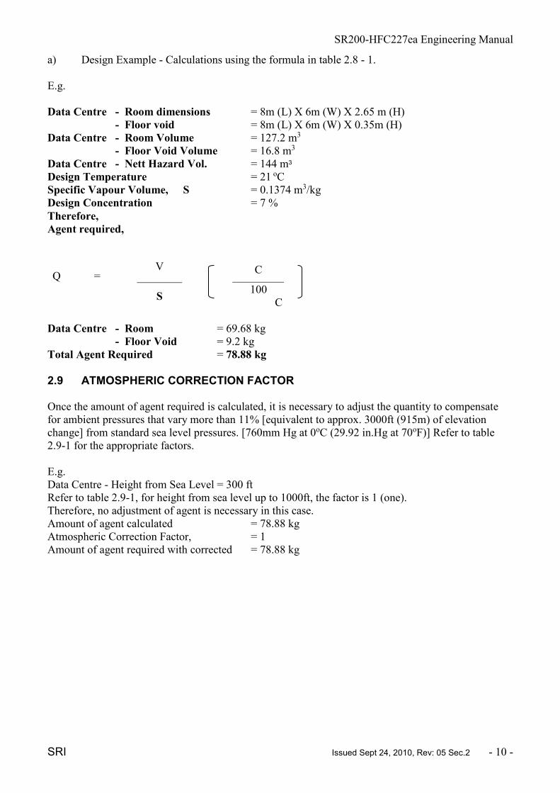
a) Design Example - Calculations using the formula in table 2.8 - 1.
E.g.
Data Centre - Room dimensions = 8m (L) X 6m (W) X 2.65 m (H)
- Floor void = 8m (L) X 6m (W) X 0.35m (H)
Data Centre - Room Volume = 127.2 m3
- Floor Void Volume = 16.8 m3
Data Centre - Nett Hazard Vol. = 144 m3
Design Temperature = 21 oC
Specific Vapour Volume, S = 0.1374 m3/kg
Design Concentration = 7 %
Therefore,
Agent required,
Q = V
C
S
100 C
Data Centre - Room = 69.68 kg
- Floor Void = 9.2 kg
Total Agent Required = 78.88 kg
2.9 ATMOSPHERIC CORRECTION FACTOR Once the amount of agent required is calculated, it is necessary to adjust the quantity to compensate
for ambient pressures that vary more than 11% [equivalent to approx. 3000ft (915m) of elevation
change] from standard sea level pressures. [760mm Hg at 0oC (29.92 in.Hg at 70oF)] Refer to table
2.9-1 for the appropriate factors.
E.g.
Data Centre - Height from Sea Level = 300 ft
Refer to table 2.9-1, for height from sea level up to 1000ft, the factor is 1 (one).
Therefore, no adjustment of agent is necessary in this case.
Amount of agent calculated = 78.88 kg
Atmospheric Correction Factor, = 1
Amount of agent required with corrected = 78.88 kg

SR200-HFC227ea Engineering Manual
SRI Issued Sept 24, 2010, Rev: 05 Sec.2 - 11 -
Table 2.9-1 Atmospheric Correction factors
Equivalent
Altitude Enclosure Pressure Atmospheric
Ft km psia mm Hg Correction Factor
-3,000 -0.92 16.25 840 1.11
-2,000 -0.61 15.71 812 1.07
-1,000 -0.3 15.23 787 1.04
0 0 14.71 760 1.00
1,000 0.3 14.18 733 0.96
2,000 0.61 13.64 705 0.93
3,000 0.91 13.12 678 0.89
4,000 1.22 12.58 650 0.86
5,000 1.52 12.04 622 0.82
6,000 1.83 11.53 596 0.78
7,000 2.13 11.03 570 0.75
8,000 2.45 10.64 550 0.72
9,000 2.74 10.22 528 0.69
10,000 3.05 9.77 505 0.66
2.10 DETERMINE THE CYLINDER SIZE REQUIRED
The SR200-HFC227ea system has the following cylinder sizes available. The filling ranges of the
respective cylinders are indicated. Refer to table 2.10-1 for the cylinder sizes and capacity.
Table 2.10-1 Cylinder Size
Cylinder Capacity Minimum filling Maximum Filling
(L) (kg) (kg)
32 16 32
52 26 52
100 50 100
120 60 120
150 75 150
180 90 180
200 100 200
E.g.
Amount of agent required, HFC-227ea = 78.88 kg
Actual supplied (roundup to 0.5kg) = 79 kg
Cylinder size required = 100 L
(refer to above table 2.10-1)

SR200-HFC227ea Engineering Manual
SRI Issued Sept 24, 2010, Rev: 05 Sec.2 - 12 -
2.11 DETERMINE THE NOZZLE QUANTITY AND LOCATIONS
The number of nozzles required is based on the hazard site, its layout, the flow and the coverage
provided by the nozzle. The nozzles are available in both 180o and 360o discharge patterns. The
nominal sizes of the nozzle are: 1/2”, ¾”, 1", 1 ¼”, 11/2" and 2".
When considering the optimum nozzle location, the following criteria should be taken into account:-
• Nozzle location is affected by the shape / layout of the hazard.
• The maximum discharge radius is 7.92m (26ft) for both the 360o and 180o nozzle. (see Figure
2.11-1)
• The maximum area coverage for both nozzles is 125.4m2 (1350ft2).
• Maximum nozzle height coverage is 4.87m (16ft) (Note : use additional rows of nozzles for
greater heights)
• Maximum distance between nozzles should not exceed 11.2m (36.7ft).
• 180o nozzles must be mounted adjacent to a wall and must be located to cover the entire area.
The maximum distance from wall is 300mm and the minimum distance is 150mm, measured
from center of nozzle to the wall.
• 300mm (1ft) minimum void (sub-floors, false / suspended ceilings) height. Consider additional
nozzles coverage in the void due to congestion of wirings, cables and equipment within the
void(s)
• Nozzle orifices must not be aimed where they may discharge into nearby objects.
Additional nozzles may be required where obstructions such as beams or cable trays which could
prevent or delay the creation of a uniform agent / air mixture.
Fig. 2.11-1 – Nozzle Discharge Radius
IMPORTANT: Though a single nozzle can cover an area of 125.4m2, consideration must be given to
the required quantity of gas which may be too much for a single nozzle to discharge. Therefore, it will
be necessary to add additional nozzles in the enclosure.

SR200-HFC227ea Engineering Manual
SRI Issued Sept 24, 2010, Rev: 05 Sec.2 - 13 -
2.12 DISTRIBUTION PIPING REQUIREMENTS
For estimation of pipe sizes refer to table 2.12-1. Generally, one size larger pipe bore should be
selected when estimating for large systems, and / or long pipe runs. The VdS computer calculations
will be able to verify the piping distribution network. Since HFC-227ea is a liquefied gas, systems are
stored and discharged as a dual-phase gas; the calculations are far more complex and have more
limitations when compared to inert gas systems. There are several limits which need to be included in
the design of the pipe work. They are:-
• Flow split on a thru tee is between 10 : 30
• Flow split on a bull tee is between 30 : 70
• All tee outlets must be in the same horizontal plane
• A minimum length of 10 times the nominal pipe diameter is needed around tee splits before
any change of direction.
30-70%
30-70% 30-70%
30-70%
100%
100%
Flow Split on a Bull Tee
(Horizontal)
Flow Split on a Bull Tee
(Vertical)
100%
70 - 90%
10 - 30%
Flow Split on Side Tee
• The maximum elevation difference in pipe runs should be as follows:-
a) If nozzles are only located above the tank outlet, then the maximum elevation
difference between the tank outlet and the furthest horizontal pipe run or discharge
nozzle shall not exceed 9.1m (30ft).
b) If nozzles are only located below the container outlet, then the maximum elevation
difference between the tank outlet and the furthest horizontal pipe run or discharge
nozzle (whichever is furthest) shall not exceed 9.1m (30ft).
c) If nozzles are located both above and below the tank outlet, then the maximum
elevation difference between the furthest horizontal pipe run or discharge nozzles
(whichever is furthest) shall not exceed 9.1m (30ft)
Note 1: System designers should aim to design as far as possible balanced pipe networks, use
minimum length of pipes and elbows, maximize pipe volume before the first tee and incorporate
similar pipe run lengths to the nozzles.
Note 2: These rules only serves as a guide for initial design and estimation only. The final design
needs to be verified by computer calculations.

SR200-HFC227ea Engineering Manual
SRI Issued Sept 24, 2010, Rev: 05 Sec.2 - 14 -
Table 2.12-1 Pipe Size Estimation
Nominal Gas Flow Rate Nominal Pipe Size Nominal Pipe Size
Minimum
(kg)
Minimum
(lb)
Maximum
(kg)
Maximum
(lb) DN (mm) Inches
3 1 13 30 15 ½
7 20 25 55 20 ¾
14 35 38 85 25 1
26 60 56 125 32 1 ¼
40 90 90 200 40 1 ½
60 140 136 300 50 2
91 200 250 550 65 2 ½
136 300 402 990 80 3
250 550 540 1250 100 4
Note: The above table is only a guide to estimate the pipe work and is for schedule 40 pipe.
The minimum design working pressure at 21oC (70oF) for the Halocarbon Gas Agent System Piping
shall be as per table 2.12-2 :-
Table 2.12-2
Minimum Design Pressure at 21oC (70oF)
Agent Container Charging
Pressure at 21oC (70oF) – psi
Minimum Piping Design
pressure at 21oC (70oF) – psi
360 416
600 820
* Source NFPA2001 – 2008 edition
For the distribution pipe network, the piping material and fittings used shall be rated at 1000 psi
working pressure.
2.13 CALCULATING THE QUANTITY OF AGENT THROUGH EACH NOZZLE
Based on the example mentioned, 2 nozzles are required for the respective area coverage. Since 2
voids are being protected with a single cylinder, the percentage of agent split at tees must be calculated
to meet the minimum requirements.
Data Centre - Room = 69.68 kg
- Floor Void = 9.2 kg
Total agent required, Room + Floor Void =78.88 kg
Percentage of Agent required at Room = 69.68/78.88 X 100
= 88.33%
Percentage of Agent required at Floor Void = 9.2/78.88 X 100
= 11.66%
Note: If the system is designed to protect 2 areas simultaneously in which the percentage of agent split
is less than 10%, consider adding additional agent to the void to meet the requirement. However, if the

SR200-HFC227ea Engineering Manual
SRI Issued Sept 24, 2010, Rev: 05 Sec.2 - 15 -
protected area is a normally occupied area and the additional gas required exceeds the NOAEL value,
a separate cylinder and distribution piping is recommended.
2.14 LAYOUT OF CYLINDERS AND MANIFOLD CONFIGURATION
Once the flow rate has been established, a suitable location for the cylinder storage has to be
determined to begin design of the pipe distribution network. The criteria for the storage area were
discussed in 2.3.8. The cylinders and manifold layout can be configured depending on the space
available. An example is shown in the drawing and component data section.
NOTE: Where multiple cylinders are connected to a manifold, all cylinders MUST be of equal size
and filling capacity.
2.15 COMPUTER CALCULATIONS- VdS PROGRAM The computer program will calculate and verify / determine the following:-
1) Piping dimensions
2) Maximum pressure in distribution pipe work
3) Orifice hole(s) diameter for each individual discharge nozzle
4) Agent gas concentration after 10 seconds for each protected void. 5) Final Agent concentration for each protected void after total discharge. 6) Discharge time at nozzle(s)
2.16 PREPARATION OF CONTRACT DRAWINGS 2.16.1 Isometric Drawings The isometric drawing shall be included as part of the calculation package and should show the
following:-
a) Pipe diameters and length
b) Nozzle flow rates (kg/sec) c) Contract reference number
d) System title / name
e) Node numbers
f) Number of revision(s) if any
g) Name of Design Engineer
2.16.2 General Arrangement Drawings General arrangement drawings to be drawn according to scale, dimensional plans and evaluations of
the hazard showing:-
a) main structural features
b) pipe routing c) bracket positions and details
d) pipe specifications e) Cylinder(s) location
f) manifold position(s)
g) Nozzle(s) location h) Detector(s) location i) Audio & Visual Alarm equipment location
j) Bill of material(s)
SR200-HFC227ea Engineering Manual
SRI Issued Sept 24, 2010, Rev: 05 Sec.2 - 16 -
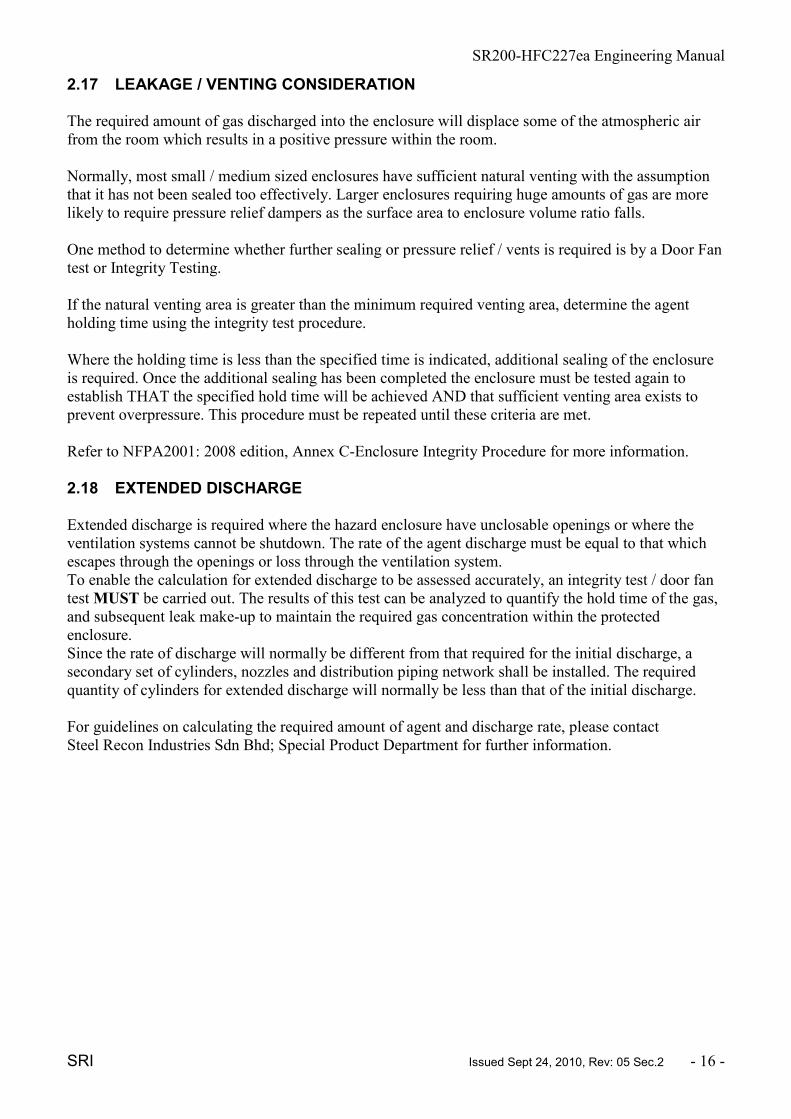
2.17 LEAKAGE / VENTING CONSIDERATION The required amount of gas discharged into the enclosure will displace some of the atmospheric air
from the room which results in a positive pressure within the room.
Normally, most small / medium sized enclosures have sufficient natural venting with the assumption
that it has not been sealed too effectively. Larger enclosures requiring huge amounts of gas are more
likely to require pressure relief dampers as the surface area to enclosure volume ratio falls.
One method to determine whether further sealing or pressure relief / vents is required is by a Door Fan
test or Integrity Testing.
If the natural venting area is greater than the minimum required venting area, determine the agent
holding time using the integrity test procedure.
Where the holding time is less than the specified time is indicated, additional sealing of the enclosure
is required. Once the additional sealing has been completed the enclosure must be tested again to
establish THAT the specified hold time will be achieved AND that sufficient venting area exists to
prevent overpressure. This procedure must be repeated until these criteria are met.
Refer to NFPA2001: 2008 edition, Annex C-Enclosure Integrity Procedure for more information.
2.18 EXTENDED DISCHARGE Extended discharge is required where the hazard enclosure have unclosable openings or where the
ventilation systems cannot be shutdown. The rate of the agent discharge must be equal to that which
escapes through the openings or loss through the ventilation system.
To enable the calculation for extended discharge to be assessed accurately, an integrity test / door fan
test MUST be carried out. The results of this test can be analyzed to quantify the hold time of the gas,
and subsequent leak make-up to maintain the required gas concentration within the protected
enclosure.
Since the rate of discharge will normally be different from that required for the initial discharge, a
secondary set of cylinders, nozzles and distribution piping network shall be installed. The required
quantity of cylinders for extended discharge will normally be less than that of the initial discharge.
For guidelines on calculating the required amount of agent and discharge rate, please contact
Steel Recon Industries Sdn Bhd; Special Product Department for further information.

SR200-HFC227ea Engineering Manual
SRi Issued Sept 24, 2010, Rev: 05 Sec.3 - 17 - STEEL RECON INDUSTRIES SDN BHD RESERVES THE RIGHT TO CHANGE THE TECHNICAL CONTENTS WITHOUT PRIOR NOTICE.
SR200-HFC227ea GAS SYSTEM
ENGINEERING MANUAL
3. DRAWINGS AND COMPONENT DATA
3.1. GENERAL
The SR200-HFC227ea gas system consists of field pipe work connected to a cylinder(s) through a
manifold(if required), distribution pipe network and nozzles.
At a reference temperature of 21oC, the SR200-HFC227ea is stored at 25 bar within each cylinder.
The proprietary system components, from cylinders to nozzles, are delivered in loose kit form and the
items are bolted to a wall or solid framework.
Each system is designed specifically for the area which it is protecting. Gas discharge times and gas
distribution is achieved by the correct sizing of the orifice holes at the nozzle with the size engraved
on the body. The General Arrangement Drawings of piping runs can affect the final diameter of the
orifices, therefore "as built" drawings must be done to enable all orifices to be calculated and drilled to
suite.
The SR200-HFC227ea system is operated by an electrical signal to a solenoid actuating device on the
master or pilot cylinder. Operation of the said cylinder will pressurize the pneumatic actuating line
which will operate the pneumatic release pistons on the slave cylinders causing these cylinders to
discharge.
Further details on the individual components of the system are given on the relevant Data Sheets and
cross referenced to the Parts List on the typical Piping and Instrumentation Diagram. (Drawing no:
SR200-P&ID-001)
3.2. EQUIPMENT DATA SHEETS
Data Sheet No. Description Approval / Type
001
Exploded View of a typical SR200-HFC227ea Gas
Suppression System Reference list
n/a
002
P & I Diagram Reference list for a typical SR200-
HFC227ea Gas Suppression System
n/a
003 SR200-HFC227ea Cylinders Assembly
TPED 1999/36/CE or
acc. to International
Standards
004-1 SR200-HFC227ea Valve Assembly Type DN49 G312003
004-2 SR200-HFC227ea Valve Assembly Type DN33 G312003
005 Cylinder Label n/a
006 Assembly Pressure Gauge G308005 Type
111.12.040
SR200-HFC227ea Engineering Manual
SRi Issued Sept 24, 2010, Rev: 05 Sec.3 - 18 - STEEL RECON INDUSTRIES SDN BHD RESERVES THE RIGHT TO CHANGE THE TECHNICAL CONTENTS WITHOUT PRIOR NOTICE.
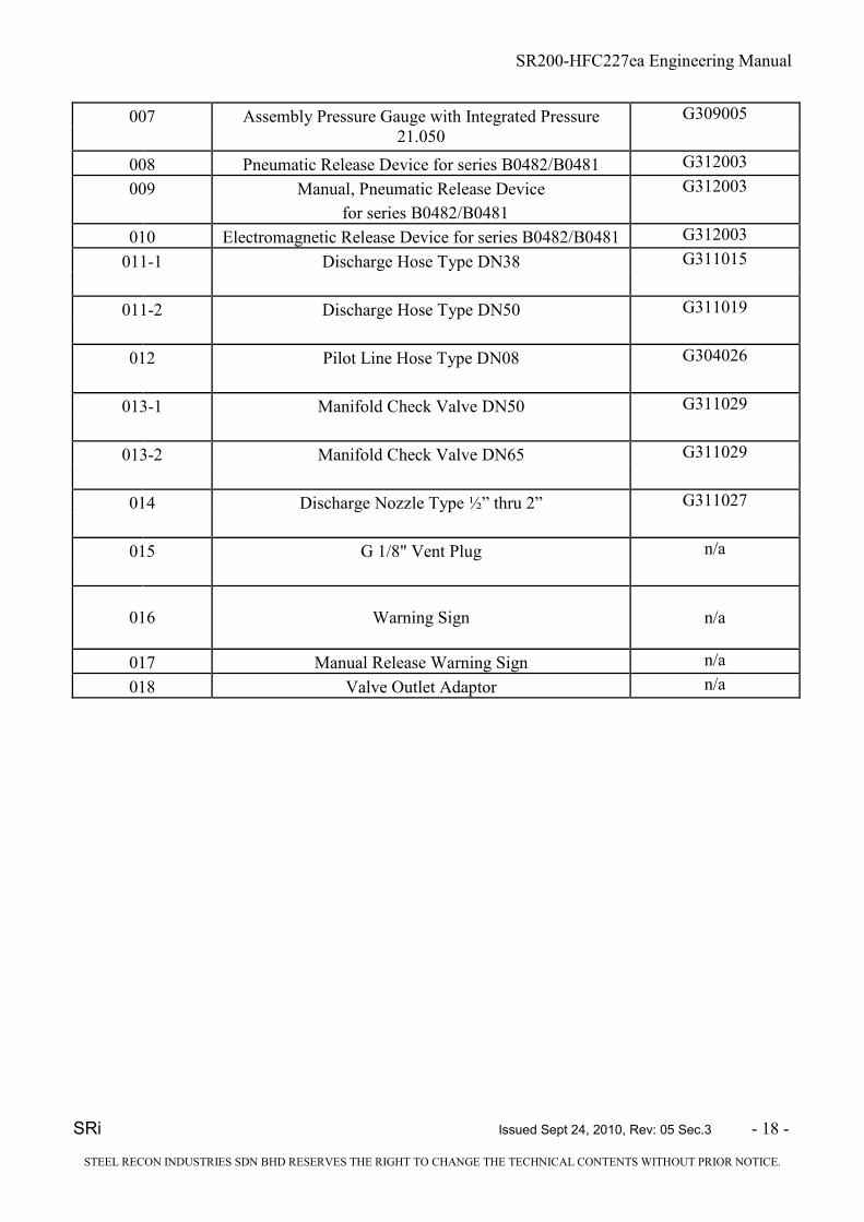
007 Assembly Pressure Gauge with Integrated Pressure G309005
21.050
008 Pneumatic Release Device for series B0482/B0481 G312003
009 Manual, Pneumatic Release Device G312003
for series B0482/B0481
010 Electromagnetic Release Device for series B0482/B0481 G312003
011-1 Discharge Hose Type DN38 G311015
011-2 Discharge Hose Type DN50 G311019
012 Pilot Line Hose Type DN08 G304026
013-1 Manifold Check Valve DN50 G311029
013-2 Manifold Check Valve DN65 G311029
014 Discharge Nozzle Type ½” thru 2” G311027
015 G 1/8" Vent Plug n/a
016 Warning Sign n/a
017 Manual Release Warning Sign n/a
018 Valve Outlet Adaptor n/a

SR200-HFC227ea Engineering Manual
SRi Issued Sept 24, 2010, Rev: 05 Sec.3 - 19 - STEEL RECON INDUSTRIES SDN BHD RESERVES THE RIGHT TO CHANGE THE TECHNICAL CONTENTS WITHOUT PRIOR NOTICE.
Exploded View Typical Installation Reference List 001
(Ref. Drw. No. SR200-EXP-001)
Ref Description Part No. Data Sheet No.
1 Manual, Pneumatic Release Actuator ING-012 009
2 Electromagnetic Release Device ING-013 010
3 SR200-HFC227ea Valve Assembly
Type DN49
XXX 004-1
4 Pressure Gauge with XXX 009
integrated pressure switch
5 Pilot Line Hose Type DN08 SPS-SR-008 012
6 Cylinder Label XXX 005
7 Pneumatic Release Device ING-019 008
8 Check Valve DN65 SPS-1C-006- 013-2
65MM
9 G 1/8" vent plug ING031 014
10 Discharge Hose Type DN50 SPS-SR-005-50MM 011-2
11
SR200-HFC227ea Cylinder
Assembly SPS227-CS 003
12 Manifold (by others) Not Applicable Not Applicable

SR200-HFC227ea Engineering Manual
SRi Issued Sept 24, 2010, Rev: 05 Sec.3 - 20 -
STEEL RECON INDUSTRIES SDN BHD RESERVES THE RIGHT TO CHANGE THE TECHNICAL CONTENTS WITHOUT PRIOR NOTICE.
SR200-HFC227ea Engineering Manual
SRi Issued Sept 24, 2010, Rev: 05 Sec.3 - 21 - STEEL RECON INDUSTRIES SDN BHD RESERVES THE RIGHT TO CHANGE THE TECHNICAL CONTENTS WITHOUT PRIOR NOTICE.
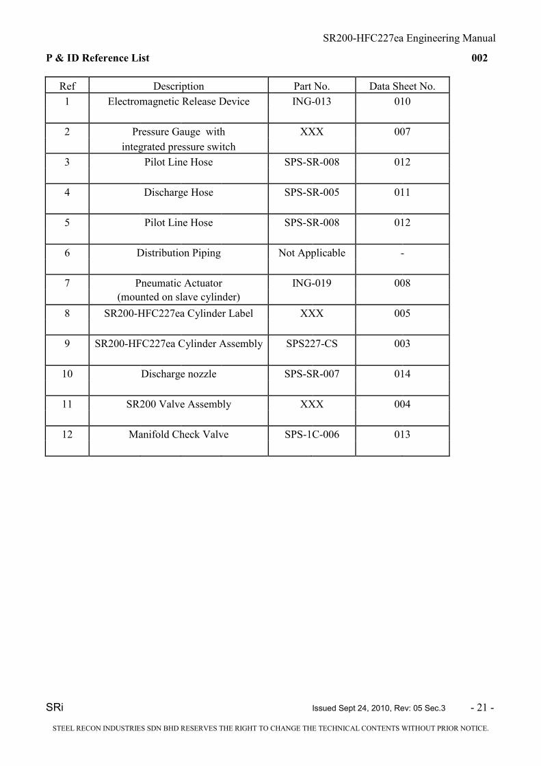
P & ID Reference List 002
Ref Description Part No. Data Sheet No.
1 Electromagnetic Release Device ING-013 010
2 Pressure Gauge with XXX 007
integrated pressure switch
3 Pilot Line Hose SPS-SR-008 012
4 Discharge Hose SPS-SR-005 011
5 Pilot Line Hose SPS-SR-008 012
6 Distribution Piping Not Applicable -
7 Pneumatic Actuator ING-019 008
(mounted on slave cylinder)
8 SR200-HFC227ea Cylinder Label XXX 005
9 SR200-HFC227ea Cylinder Assembly SPS227-CS 003
10 Discharge nozzle SPS-SR-007 014
11 SR200 Valve Assembly XXX 004
12 Manifold Check Valve SPS-1C-006 013

SR200-HFC227ea Engineering Manual
SRi Issued Sept 24, 2010, Rev: 05 Sec.3 - 22 -
STEEL RECON INDUSTRIES SDN BHD RESERVES THE RIGHT TO CHANGE THE TECHNICAL CONTENTS WITHOUT PRIOR NOTICE.

SR200-HFC227ea Engineering Manual
SRi Issued Sept 24, 2010, Rev: 05 Sec.3 - 23 - STEEL RECON INDUSTRIES SDN BHD RESERVES THE RIGHT TO CHANGE THE TECHNICAL CONTENTS WITHOUT PRIOR NOTICE.
SR200-HFC227ea Cylinder Assembly 003
Remarks:
Each cylinder is fitted with a valve outlet cap.
WARNING:
THE VALVE OUTLET CAP MUST ALWAYS BE FITTED ONTO THE CYLINDER,
IRRESPECTIVE OF WHETHER THE CYLINDER IS FULL OR EMPTY, WHEN IT IS NOT
CONNECTED TO THE PIPE NETWORK OR MANIFOLD.
A
Specification:
Materials : MSteel
Filling : 0.5kg /L up to maximum of 1 kg/L
Filling Pressure : 25 Bar @ 21oC
Test Pressure : 50 Bar
Standard of Compliance : TPED 1999/36/Ce or acc. to International Standards
Colour : Red
Part No. Capacity (l) Valve Outlet Size Dim. A (mm) +5 Cylinder Dia.
(mm)
SPS227-CS-032-33 32 DN33 522.4 324
SPS227-CS-052-33 52 DN33 782.4 324
SPS227-CS-100-33 100 DN33 963 406
SPS227-CS-120-49 120 DN49 1126 406
SPS227-CS-150-49 150 DN49 1372 406
SPS227-CS-180-49 180 DN49 1268 462
SPS227-CS-200-49 200 DN49 1398 462
SR200-HFC227ea Engineering Manual
SRi Issued Sept 24, 2010, Rev: 05 Sec.3 - 24 - STEEL RECON INDUSTRIES SDN BHD RESERVES THE RIGHT TO CHANGE THE TECHNICAL CONTENTS WITHOUT PRIOR NOTICE.
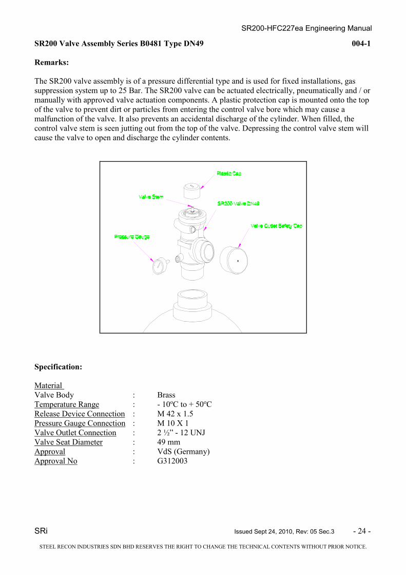
SR200 Valve Assembly Series B0481 Type DN49 004-1
Remarks:
The SR200 valve assembly is of a pressure differential type and is used for fixed installations, gas
suppression system up to 25 Bar. The SR200 valve can be actuated electrically, pneumatically and / or
manually with approved valve actuation components. A plastic protection cap is mounted onto the top
of the valve to prevent dirt or particles from entering the control valve bore which may cause a
malfunction of the valve. It also prevents an accidental discharge of the cylinder. When filled, the
control valve stem is seen jutting out from the top of the valve. Depressing the control valve stem will
cause the valve to open and discharge the cylinder contents.
Specification:
Material
Valve Body : Brass
Temperature Range : - 10oC to + 50oC
Release Device Connection : M 42 x 1.5
Pressure Gauge Connection : M 10 X 1
Valve Outlet Connection : 2 ½” - 12 UNJ
Valve Seat Diameter : 49 mm
Approval : VdS (Germany)
Approval No : G312003

SR200-HFC227ea Engineering Manual
SRi Issued Sept 24, 2010, Rev: 05 Sec.3 - 25 - STEEL RECON INDUSTRIES SDN BHD RESERVES THE RIGHT TO CHANGE THE TECHNICAL CONTENTS WITHOUT PRIOR NOTICE.
SR200 Valve Assembly Series B0482 Type DN33 004-2
Remarks:
The SR200 valve assembly is of a pressure differential type and is used for fixed installations, gas
suppression system up to 25 Bar. The SR200 valve can be actuated electrically, pneumatically and / or
manually with approved valve actuation components. A plastic protection cap is mounted onto the top
of the valve to prevent dirt or particles from entering the control valve bore which may cause a
malfunction of the valve. It also prevents an accidental discharge of the cylinder. When filled, the
control valve stem is seen jutting out from the top of the valve. Depressing the control valve stem will
cause the valve to open and discharge the cylinder contents.
Specification:
Material
Valve Body : Brass
Temperature Range : - 10oC to + 50oC
Release Device Connection : M 42 x 1.5
Pressure Gauge Connection : M 10 X 1
Valve Outlet Connection : 1 7/8” - 12 UNJ
Valve Seat Diameter : 33 mm
Approval : VdS (Germany)
Approval No : G312003

SR200-HFC227ea Engineering Manual
SRi Issued Sept 24, 2010, Rev: 05 Sec.3 - 26 - STEEL RECON INDUSTRIES SDN BHD RESERVES THE RIGHT TO CHANGE THE TECHNICAL CONTENTS WITHOUT PRIOR NOTICE.
SR200-HFC227ea Cylinder Labels 005
Remarks:
Cylinder Label
Specification:
Material : Vinyl
Size : 242mm (L) X 190mm (W)
Part No : XXX
SRSRSRSR----200200200200 (HFC-227ea)
GAS FIRE SUPPRESSION SYSTEM
CYLINDER CAPACITY : LITRES GAS CAPACITY : kg GROSS WEIGHT (APPROX.) : kg CYLINDER TEST PRESSURE : 50 BAR
FILLING PRESSURE : 25 BAR @ 21 O C
TEMPERATURE RANGE : -10oC to + 50
oC
GENERAL
This cylinder shall be recharged by an authorized distributor only with agent specified by the manufacturer.
The system shall be maintained by an authorized distributor. If the cylinder indicates a pressure loss of more
than 5% (adjusted to ambient temperature) from the filling pressure, or if the weight of the cylinder shows a
loss of more than 10% it must be removed and sent for refilling.
MANUFACTURER: APPROVED BY
Steel Recon Industries Sdn Bhd
No. 8, Jalan Subang 7, Taman Perindustrian Subang,
47610 Subang Jaya, Selangor, M alaysia.
Tel : +603 – 8023 2323
Fax : +603 – 8023 2828
E-mail : info @ sri.com.my
spd @ sri.com.my
international.sales @ sri.com.my
NON-
FLAMMABLE
GAS
SR200-HFC227ea Engineering Manual
SRi Issued Sept 24, 2010, Rev: 05 Sec.3 - 27 - STEEL RECON INDUSTRIES SDN BHD RESERVES THE RIGHT TO CHANGE THE TECHNICAL CONTENTS WITHOUT PRIOR NOTICE.
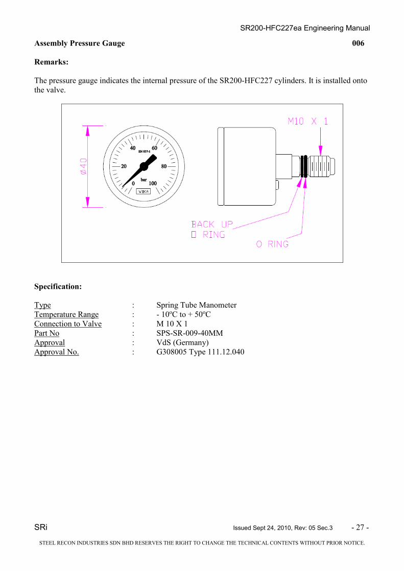
Assembly Pressure Gauge 006
Remarks:
The pressure gauge indicates the internal pressure of the SR200-HFC227 cylinders. It is installed onto
the valve.
Specification:
Type : Spring Tube Manometer
Temperature Range : - 10oC to + 50oC
Connection to Valve : M 10 X 1
Part No : SPS-SR-009-40MM
Approval : VdS (Germany)
Approval No. : G308005 Type 111.12.040

SR200-HFC227ea Engineering Manual
SRi Issued Sept 24, 2010, Rev: 05 Sec.3 - 28 - STEEL RECON INDUSTRIES SDN BHD RESERVES THE RIGHT TO CHANGE THE TECHNICAL CONTENTS WITHOUT PRIOR NOTICE.
Assembly Pressure Gauge with integrated pressure switch 007
Remarks:
A pressure gauge with integrated pressure switch can be used in place of the standard pressure gauge
to monitor the pressure within the cylinder and provide a signal when the pressure drops below 22.5
Bar ± 0.9.
Specification:
Type : PGS21.050
Temperature Range : - 10oC to + 50oC
Connection to Valve : M 10 X 1
Indication Range : 0 - 40 Bar
Nominal Size : 50 mm
Electrical Data
Contact Pin and Lug : Gold Plated
Switch Voltage : 4.5 to 24 VDC
Switch Current : 5 mA to 100 mA
Contact Load : max 3 W
Switch Point : 22.5 Bar
Setting : increasing pressure max 23.4 Bar
decreasing pressure min 21.6 Bar
Part no : XXX
Approval : VdS (Germany)
Approval No. : G309005

SR200-HFC227ea Engineering Manual
SRi Issued Sept 24, 2010, Rev: 05 Sec.3 - 29 - STEEL RECON INDUSTRIES SDN BHD RESERVES THE RIGHT TO CHANGE THE TECHNICAL CONTENTS WITHOUT PRIOR NOTICE.
Pneumatic Release Device for series B0482/B0481 008
Remarks:
The pneumatic actuator is used to actuate the SR200-HFC227ea valve pneumatically. It is fitted on the
slave cylinder valve.
Specification:
Material
Body : Brass
Min. Actuating Pressure : 21 Bar
Max. Working Pressure : 240 Bar
Valve Connection : M 42 x 1.5
Pneumatic Connection : 1/8" BSP
Part No : ING019
Approval : Vds (Germany)
Approval No. : G312003

SR200-HFC227ea Engineering Manual
SRi Issued Sept 24, 2010, Rev: 05 Sec.3 - 30 - STEEL RECON INDUSTRIES SDN BHD RESERVES THE RIGHT TO CHANGE THE TECHNICAL CONTENTS WITHOUT PRIOR NOTICE.
Manual Actuator Release Device for series B0482/B0481 009
Remarks:
The manual actuator is used to actuate the SR200-HFC227ea valve by manual means. It can be fitted
either on the cylinder valve or on the electric solenoid actuator.
Specification:
Material
Body : Brass
Lever : Stainless Steel
Safety Pin : Stainless Steel
Manual Actuating Force : < 150 N
Max. Actuating Pressure : 340 Bar
Valve Connection : M 42 x 1.5
Part No : ING012
Approval : VdS (Germany)
Approval No : G312003
SR200-HFC227ea Engineering Manual
SRi Issued Sept 24, 2010, Rev: 05 Sec.3 - 31 - STEEL RECON INDUSTRIES SDN BHD RESERVES THE RIGHT TO CHANGE THE TECHNICAL CONTENTS WITHOUT PRIOR NOTICE.
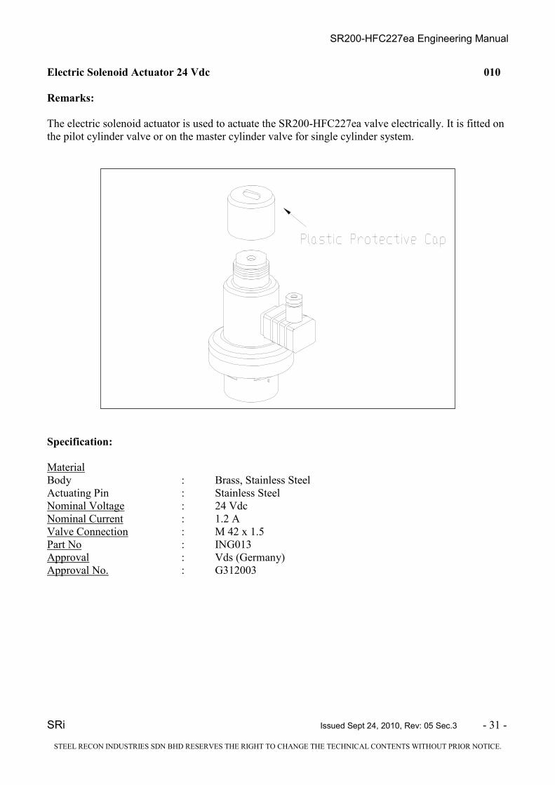
Electric Solenoid Actuator 24 Vdc 010
Remarks:
The electric solenoid actuator is used to actuate the SR200-HFC227ea valve electrically. It is fitted on
the pilot cylinder valve or on the master cylinder valve for single cylinder system.
Specification:
Material
Body : Brass, Stainless Steel
Actuating Pin : Stainless Steel
Nominal Voltage : 24 Vdc
Nominal Current : 1.2 A
Valve Connection : M 42 x 1.5
Part No : ING013
Approval : Vds (Germany)
Approval No. : G312003

SR200-HFC227ea Engineering Manual
SRi Issued Sept 24, 2010, Rev: 05 Sec.3 - 32 - STEEL RECON INDUSTRIES SDN BHD RESERVES THE RIGHT TO CHANGE THE TECHNICAL CONTENTS WITHOUT PRIOR NOTICE.
Discharge Hose Type DN38 011-1
Remarks:
The discharge hose type DN38 is used for the valve assembly series B0482 typ DN33 for connection
to the check valve DN50 where multiple cylinders are connected to a common manifold assembly.
Specification:
Material : Synthetic Rubber Hose with 2 high tensile steel wire
braids reinforcement
Max. Working Pressure : 40 Bar
Temperature Range : - 10oC to + 50oC
Hose connections
A : 1 7/8” - 12 UNJ
B : 2” BSP
C (Overall Length) : 790mm
Part No. : SPS-SR-005-38MM
Approval : VdS (Germany)
Approval no. : G311015
SR200-HFC227ea Engineering Manual
SRi Issued Sept 24, 2010, Rev: 05 Sec.3 - 33 - STEEL RECON INDUSTRIES SDN BHD RESERVES THE RIGHT TO CHANGE THE TECHNICAL CONTENTS WITHOUT PRIOR NOTICE.
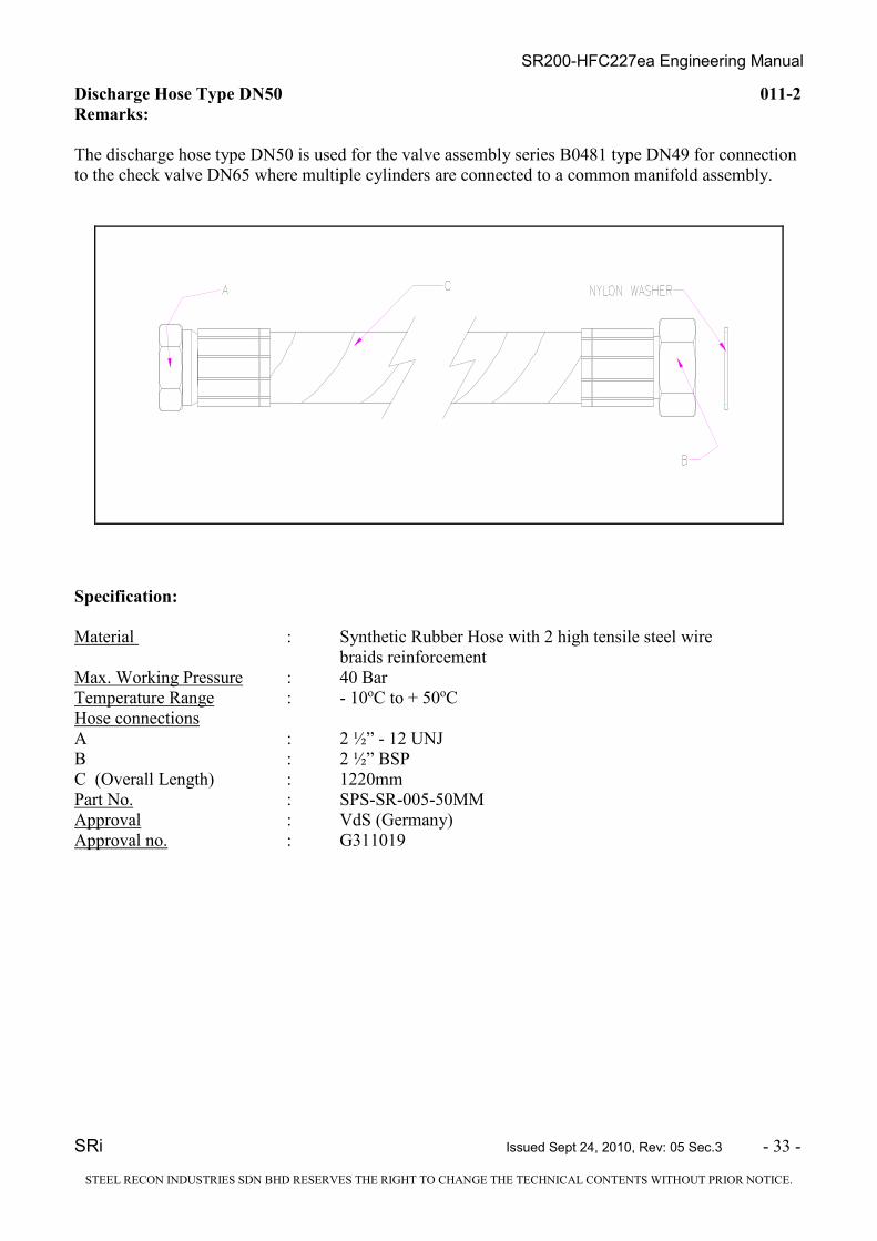
Discharge Hose Type DN50 011-2
Remarks:
The discharge hose type DN50 is used for the valve assembly series B0481 type DN49 for connection
to the check valve DN65 where multiple cylinders are connected to a common manifold assembly.
Specification:
Material : Synthetic Rubber Hose with 2 high tensile steel wire
braids reinforcement
Max. Working Pressure : 40 Bar
Temperature Range : - 10oC to + 50oC
Hose connections
A : 2 ½” - 12 UNJ
B : 2 ½” BSP
C (Overall Length) : 1220mm
Part No. : SPS-SR-005-50MM
Approval : VdS (Germany)
Approval no. : G311019

SR200-HFC227ea Engineering Manual
SRi Issued Sept 24, 2010, Rev: 05 Sec.3 - 34 - STEEL RECON INDUSTRIES SDN BHD RESERVES THE RIGHT TO CHANGE THE TECHNICAL CONTENTS WITHOUT PRIOR NOTICE.
Pilot Line Hose Type DN08 012
Remarks:
The SR200-HFC227ea pilot line hose is used to connect the pneumatic actuators from the master
cylinder to slave cylinder(s). Each hose is fitted with a galvanized steel male connection fitting. A 1/8”
nipple is used for connection to the master cylinder.
Specification:
Material : Synthetic Rubber Hose with 2 high tensile steel wire
braids reinforcement
Max. Working Pressure : 350 Bar
Temperature Range : - 15oC to + 50oC
Hose Connections : 1/8" BSP
Fitting Connections : 1/8" BSP
Approval : Vds (Germany)
Approval No : G304027
Part No. Overall Length - A (mm)
SPS-SR-008-560MM 560
SPS-SR-008-760MM 760

SR200-HFC227ea Engineering Manual
SRi Issued Sept 24, 2010, Rev: 05 Sec.3 - 35 - STEEL RECON INDUSTRIES SDN BHD RESERVES THE RIGHT TO CHANGE THE TECHNICAL CONTENTS WITHOUT PRIOR NOTICE.
Manifold Check Valve DN50 013-1
Remarks:
The manifold check valve is fitted on the manifold and is used to prevent loss of agent should the
system discharge while any cylinder is removed for maintenance.
Specification:
Material
Body : Gun Metal
Seat : Nylon
Washer : Zinc Plated Mild Steel
Nut : Stainless Steel
Max. Working Pressure : 34 Bar
Temperature Range : - 10oC to + 50oC
Approval : VdS (Germany)
Approval No : G311029
Size Part No. Inlet and Outlet Connection
DN50 SPS-1C-006-50MM 2” BSP

SR200-HFC227ea Engineering Manual
SRi Issued Sept 24, 2010, Rev: 05 Sec.3 - 36 - STEEL RECON INDUSTRIES SDN BHD RESERVES THE RIGHT TO CHANGE THE TECHNICAL CONTENTS WITHOUT PRIOR NOTICE.
Manifold Check Valve DN65 013-2
Remarks:
The manifold check valve is fitted on the manifold and is used to prevent loss of agent should the
system discharge while any cylinder is removed for maintenance.
Specification:
Material
Body : Gun Metal
Seat : Nylon
Washer : Zinc Plated Mild Steel
Nut : Stainless Steel
Max. Working Pressure : 34 Bar
Temperature Range : - 10oC to + 50oC
Approval : VdS (Germany)
Approval No : G311029
Size Part No. Inlet and Outlet Connection
DN65 SPS-1C-006-65MM 2 ½” BSP

SR200-HFC227ea Engineering Manual
SRi Issued Sept 24, 2010, Rev: 05 Sec.3 - 37 - STEEL RECON INDUSTRIES SDN BHD RESERVES THE RIGHT TO CHANGE THE TECHNICAL CONTENTS WITHOUT PRIOR NOTICE.
Discharge Nozzle Type ½” thru 2” 014
Remarks:
The SR200-HFC227 discharge nozzles are available in 180o or 360o discharge pattern. They are
available in 7 sizes, 1/2", ¾”, 1", 1 ¼”, 1 1/2" and 2”. The orifice holes are drilled upon completion of
the final design drawings and confirmed by computer calculations. The size of the orifice is
individually stamped onto the nozzle.
AB
B
A
180° discharge pattern
360° discharge pattern
Specification:
Material
Body : Brass
Available Nozzle Size
Nominal Size Part no Dim. A (mm) Dim. B (mm)
½” SPS-SR-007-15MM 49 31.75
¾” SPS-SR-007-20MM 54 38.1
1” SPS-SR-007-25MM 60 44.45
1 ¼” SPS-SR-007-32MM 70 57.15
1 ½” SPS-SR-007-40MM 74 63.5
2” SPS-SR-007-50MM 79 76.2
Approval : VdS (Germany)
Approval No : G311027

SR200-HFC227ea Engineering Manual
SRi Issued Sept 24, 2010, Rev: 05 Sec.3 - 38 - STEEL RECON INDUSTRIES SDN BHD RESERVES THE RIGHT TO CHANGE THE TECHNICAL CONTENTS WITHOUT PRIOR NOTICE.
1/8" BSPT Vent Plug 015
Remarks:
The 1/8" BSPT vent plug is used to cap the pneumatic actuation line. It is installed on the last slave
cylinder's pneumatic actuator. The plug relieves the pressure thorough a small orifice. This slow relief
of pressure does not affect the function of the actuating line.
Specification:
Material : S Steel
Connection : 1/8 " BSP
Part No : ING029
Orifice Size : 1.5mm

SR200-HFC227ea Engineering Manual
SRi Issued Sept 24, 2010, Rev: 05 Sec.3 - 39 - STEEL RECON INDUSTRIES SDN BHD RESERVES THE RIGHT TO CHANGE THE TECHNICAL CONTENTS WITHOUT PRIOR NOTICE.
Warning Sign 016
Remarks:
This warning label should be placed on all entrance doors to the hazard area. It comes in a yellow
background with black lettering.
WARNING!
THIS AREA IS PROTECTED BY A SR200-HFC227ea GAS FIRE
EXTINGUISHING SYSTEM.
WHEN ALARM SOUNDS OR UPON GAS DISCHARGE VACATE AREA
IMMEDIATELY.
AFTER DISCHARGE DO NOT RE-ENTER WITHOUT BREATHING
APPARATUS. VENTILATE THE AREA ONLY AFTER CONFIRMATION
THAT THE FIRE IS EXTINGUISHED OR THE DANGER OF REIGNITION
HAS PASSED.
* (YELLOW BACKGROUND)
SR200 SYSTEM HFC – 227ea
GAS FIRE SUPPRESSION SYSTEM
Specification :
Material : Vinyl
Size : 210mm (L) X 210mm (W)
Part No : ING038

SR200-HFC227ea Engineering Manual
SRi Issued Sept 24, 2010, Rev: 05 Sec.3 - 40 - STEEL RECON INDUSTRIES SDN BHD RESERVES THE RIGHT TO CHANGE THE TECHNICAL CONTENTS WITHOUT PRIOR NOTICE.
Manual Release Warning Sign 017
Remarks:
The SR200-HFC227ea manual release warning sign should be placed adjacent to the manual release
actuator. (If fitted)
CAUTION!
ENSURE HAZARD AREA IS EVACUATED
BEFORE RELEASING.
1. ROTATE SAFETY PIN TO BREAK SEAL.
2. PULL OUT SAFETY PIN
3. PULL DOWN LEVER TO ACTUATE
SYSTEM.
* (YELLOW BACKGROUND)
SR200 SYSTEM
HFC-227ea MANUAL RELEASE POINT
Specification :
Material : Vinyl
Size : 152mm (L) X 115mm (W)
Part No : ING039
SR200-HFC227ea Engineering Manual
SRi Issued Sept 24, 2010, Rev: 05 Sec.3 - 41 - STEEL RECON INDUSTRIES SDN BHD RESERVES THE RIGHT TO CHANGE THE TECHNICAL CONTENTS WITHOUT PRIOR NOTICE.
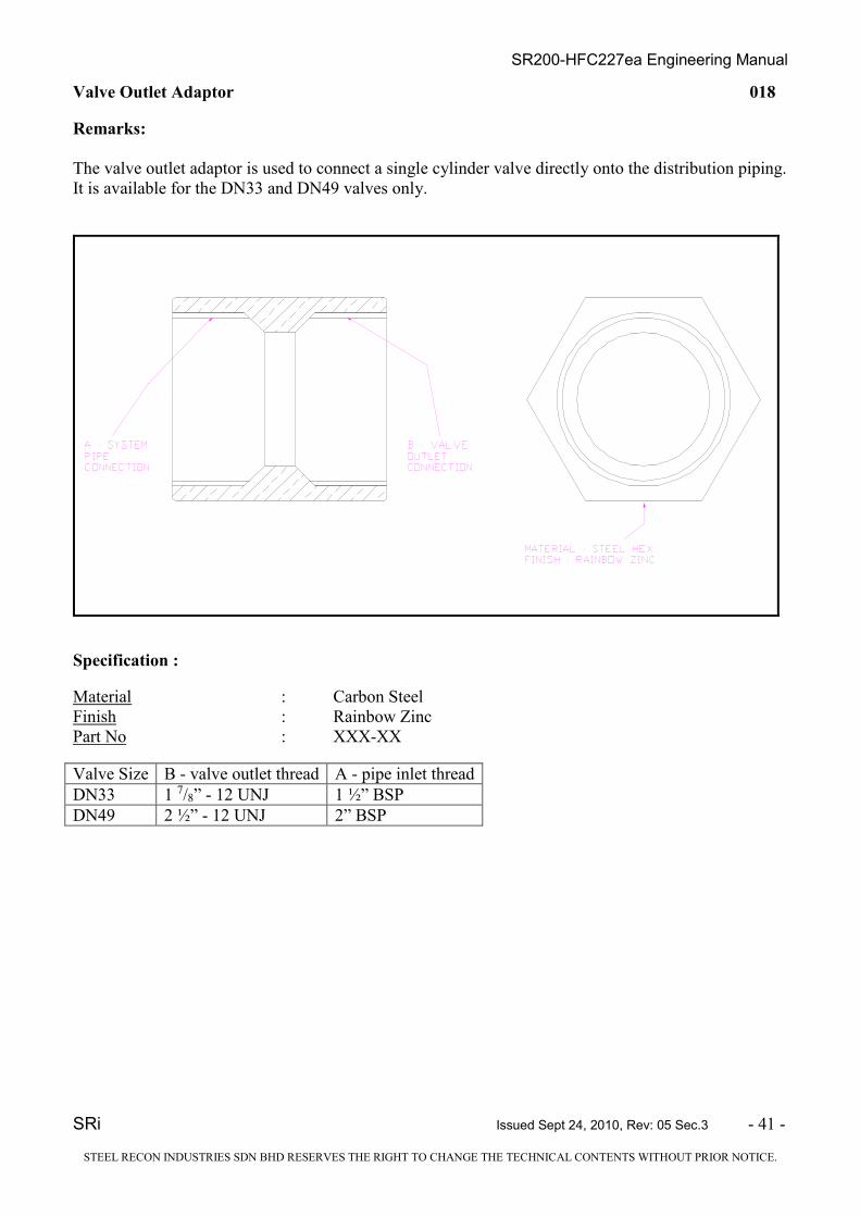
Valve Outlet Adaptor 018
Remarks:
The valve outlet adaptor is used to connect a single cylinder valve directly onto the distribution piping.
It is available for the DN33 and DN49 valves only.
Specification :
Material : Carbon Steel
Finish : Rainbow Zinc
Part No : XXX-XX
Valve Size B - valve outlet thread A - pipe inlet thread
DN33 1 7/8” - 12 UNJ 1 ½” BSP
DN49 2 ½” - 12 UNJ 2” BSP

SR200-HFC227ea Engineering Manual
SRi Issued Sept 24, 2010, Rev: 05 Sec.3 - 42 - STEEL RECON INDUSTRIES SDN BHD RESERVES THE RIGHT TO CHANGE THE TECHNICAL CONTENTS WITHOUT PRIOR NOTICE.
Cylinder Support System 019
Remarks:
The SR200 cylinder support system is used to mount the cylinder against a wall or any rigidly vertical
surface.
Specification :
Material : Mild Steel
Finish : Zinc Plated
Item Description Part No.
A 10” Cylinder Strap set c/w nut, bolt & channel XXX-XX
B 16” Cylinder Strap set c/w nut, bolt & channel XXX-XX
C 18” Cylinder Strap set c/w nut, bolt & channel XXX-XX

SR200-HFC227ea Engineering Manual
SRI Issued Sept 24, 2010, Rev: 05 Sec.2 - 2 -
SR200-HFC227ea GAS FIRE SUPPRESSION SYSTEM
ENGINEERING MANUAL
2. SYSTEM DESIGN 2.1 GENERAL The SR 200-HFC227ea Gas Fire Suppression system utilizes the halocarbon gas Heptafluoropropane
(HFC-227ea ) in NFPA 2001 and ISO 14520-1. The general requirements and design criteria are based
on both NFPA 2001 and ISO 14520-1. The SR200-HFC227ea gas fire suppression system is
employed as a total flooding system and should not be used for local application system. HFC-227ea
suppresses fire by absorbing heat energy at its molecular level faster than the heat can be generated, so
the fire cannot sustain itself. It also forms free radicals to chemically interfere with the chain reaction
of the combustion process. This makes it a highly effective fire fighting agent that is safe for people
and causes no damage to equipment.
2.2 EVALUATION OF HAZARD / RISK As a general rule, all fire protection systems begin with a risk assessment which should evaluate the
following:-
1. the consequences of material loss or interruption of services
2. what combustible materials are present
3. possible sources of ignition either internally or externally
4. evacuation of the area
5. consequences of fire spread to adjoining areas
6. whether the hazard area is or can be enclosed
This process will clarify whether an active fire protection system is required, how fast it must respond
and whether a gas extinguishing is suitable and practical.
In the design of a SR200-HFC227ea Gas Fire Suppression system, it is important to correctly define
the hazard and conduct a thorough survey to determine if the halocarbon gas system will properly
protect the enclosure / hazards.
The SR200-HFC227ea Gas Suppression system is effective to suppress the following types of fires :-
Class A - Surface Fires / Ordinary Combustible Fires
Fires which involves ordinary combustibles such as wood, paper, fabric, etc.
Class B - Flammable Liquid Fires
Fires which involves liquid hydrocarbons or polar solvents.
Class C - Flammable Gas Fires
Fires which involves gaseous hydrocarbons or polar solvents.
Class E - Energized Electrical Equipment Fires
These fires may include computer rooms, control rooms, transformers, oil switches, circuit breakers,
rotating equipment, pumps and motors.

SR200-HFC227ea Engineering Manual
SRI Issued Sept 24, 2010, Rev: 05 Sec.2 - 3 -
The halocarbon Gas Suppression system is NOT effective on the following types of fires :-
Class D - Combustible Metals
Reactive metals such as lithium, sodium, potassium, magnesium, titanium, zirconium, uranium &
plutonium.
Certain chemicals or mixture of chemicals such as cellulose nitrate and gunpowder, that is capable of
rapid oxidation in the absence of air.
OR
Chemicals capable of undergoing auto thermal decomposition, such as certain organic peroxides and
hydrazine
OR
Metal hydrides.
2.3 PLANNING In the design of a SR200-HFC227ea Gas Fire Suppression system, it is important to correctly define
the hazard and conduct a thorough survey to determine if the halocarbon gas system will properly
protect the enclosure / hazards. The halocarbon gas system should be used with an automatic early fire
detection system to prevent a deep seated fire from developing as a result of a long pre-burn time.
2.3.1 Type of Hazards Briefly describe the types of hazards being protected. Record anything unique or unusual about the
hazard.
2.3.2 Hazard / Enclosure Integrity Survey An integrity test is recommended to determine the natural venting area and the agent retention
prediction for the enclosure. One method is by a door fan test. For more information refer to
NFPA2001 -Standard for Clean Agent Fire Extinguishing Systems Annex C as well as ISO 14520
Annex E.
2.3.3 Hazard / Enclosure Atmosphere
If the hazard / enclosure is designated as explosion-proof, the control system, releasing devices,
electric valve actuators, pressure switches and pressure monitoring switches (if not approved for
hazardous environments) must be located away from the hazard area and the system must be remotely
piped to the area. Only the detectors, distribution piping, nozzles or other non-electrical parts may be
located in the hazard, alternatively explosion-proof components must be used.
2.3.4 Hazard Ventilation Considerations All electrical power sources associated with the protected hazard should be shutdown prior to system
discharge to eliminate the possibility of a fire being electrically reignited.

SR200-HFC227ea Engineering Manual
SRI Issued Sept 24, 2010, Rev: 05 Sec.2 - 4 -
2.3.5 Temperature Range Considerations For the hazard area determine the design temperature as well as the maximum ambient temperature.
The agent required is based on the expected design ambient temperature in the hazard area. If the
difference in the lowest and the highest expected ambient temperature is significant, it may be more
appropriate to calculate the concentration level at a median expected ambient temperature to ensure
that it does not exceed the NOAEL value for the agent as stated in NFPA2001 and ISO 14250 during
the highest expected temperature whilst having a sufficient extinguishing concentration during the
lowest expected temperature. The agent cylinder must be located indoors in an area with a temperature
range from 0oC to 50oC.
2.3.6 Volume Reduction In the calculation of the volume of the hazard, it is normally considered to be empty. However, if there
are fixed, non-moveable objects such as beams, columns and permanent dividers in the hazard area,
their volumes shall be deducted from the total hazard volume.
2.3.7 Reserve System If a reserve system is required, determine if it should be permanently connected or stored on the
premises. Generally, a reserve system is recommended if the hazard is located in a remote area where
there are difficulties in recharging the cylinders within a reasonable time or the system is protecting a
high risk / value hazard. The addition of a reserve system will invariably add to the job cost estimate.
2.3.8 Cylinders and Accessories Location In selection a suitable location that is acceptable with the end-user, the following guidelines must
apply:-
1. The temperature range is within the limits
2. Piping limitation are not exceeded
3. The components are not subjected to damage or vandalism
4. A manual release system is installed and accessible
5. Cylinders and actuation devices must be stored in a weatherproof area
6. If cylinders are stored in a dedicated area, ensure that the area is not used for storage of
other equipment which may add a fire risk to the room.
7. The location should be a dry area, and should not be subjected to a corrosive environment.
2.3.9 Discharge Test Generally a discharge test is not recommended due to the costs involved as well as the environmental
impact of the gas.
2.3.10 Authority Having Jurisdiction Contact the end-user or the local authority having jurisdiction to establish the requirements for the
following :-
1. Detector spacing requirements
2. Type of detection and control system that is acceptable
3. Audio and visual alarms requirements
4. Inspection of equipment
5. If reserve system is required

SR200-HFC227ea Engineering Manual
SRI Issued Sept 24, 2010, Rev: 05 Sec.2 - 5 -
2.4 SPECIFICATIONS AND PHYSICAL PROPERTIES OF HFC-227ea GAS. 2.4.1 Physical Properties of Halocarbon Agent HFC-227ea in NFPA 2001
Halocarbon agent HFC-227ea is known as Heptafluoropropane and its chemical formula is
CF3CHFCF3
Properties Value Units
Molecular Weight 170 -
Boiling Point @ 1.013 bar (absolute) -16.4 oC
Freezing Point -131 oC
Critical Temperature 101.7 oC
Critical Pressure 29 Bar
Critical Volume 274 cc/mole
Critical Density 621 kg/m3
Specific heat, liquid @ 25oC 1.184 kJ/kg oC
Specific heat, vapour @ constant
pressure (1 atm) and 25oC 0.808 kJ/kg oC
Heat of Vaporization at boiling point 132.6 kJ/kg
Thermal conductivity of liquid @ 25 oC 0.069 W/m oC
Viscosity, liquid at 25oC 0.184 centipoise
Relative dielectric strength at 1 atm at
734 mm Hg, 25oC (N2 = 1.0) 2 -
Solubility of water in agent 0.06% by weight ppm

SR200-HFC227ea Engineering Manual
SRI Issued Sept 24, 2010, Rev: 05 Sec.2 - 6 -
2.5 DESIGN FLOW CHART
Determine hazard material and required design concentration
↓
Identify individual enclosure volumes and deduct any impermeable volumes where appropriate. Calculate the hazard volume in m3
↓
Determine the hazard altitude and correction factor
↓
Calculate agent quantity required per enclosure, at minimum design temperature expected at enclosure
↓
Determine the size of cylinder needed and if necessary the no. of cylinders required
↓
Select the nozzle type and determine location(s)
↓
Determine the location of the cylinder(s) to define the manifold layout (if multiple cylinders are used) and the distribution piping. Estimate the required pipe sizes
↓
Calculate quantity of agent per nozzle and check percentage agent split at Tee’s
↓
Identify all pipe lengths, rises, falls and nozzle reference numbers. Draw the isometric layout of pipe and node system
↓
Run the computer calculation for pipe sizing, nozzle sizes and orifice sizes, the predicted agent concentration and the predicted discharge times.
↓
Prepare contract drawings
↓
Determine the leakage / venting consideration

SR200-HFC227ea Engineering Manual
SRI Issued Sept 24, 2010, Rev: 05 Sec.2 - 7 -
2.6 DEFINING THE HAZARD Defining the hazard shall include the following steps:-
1. Determine the fuel(s) within the risk which would propagate a fire once started. The fuel
with the highest required agent concentration to govern.
2. Determine the closable and unclosable openings within the hazard enclosure which may
affect the performance of the halocarbon gas system.
3. Determine whether the halocarbon gas system is to be used for extinguishing or inerting
purposes within the risk.
4. Determine the design temperature of the hazard enclosure.
5. Select the flooding factor / design concentration required for the risk. For the required
agent flooding factor / design concentration requirement see tables 2.8-1 and 2 with the
appropriate temperature.
6. All floor voids shall be included in the protection. All ceiling voids over 800mm should be
included in the protection. Ceiling voids less than 800mm may require protection: a) if a
hazard exists within them, b) if there are unclosable openings into the main hazard, c) if the
void forms part of the ventilation system.
2.7 DETERMINE THE HAZARD VOLUME The hazard enclosure volume needs to be determined in order to calculate the amount of agent
required and the number of cylinders used. Calculate the volume using the internal dimensions of the
enclosure in meters.
If the enclosure has solid immovable objects such as beams and columns, their volumes must be
deducted to determine the nett hazard volume.
2.8 DETERMINE THE AGENT REQUIRED In determining the amount of agent required the following design concentrations (as specified in
NFPA 2001: 2008 edition*) are used:-
Agent Class A Design Concentration Class B Design
HFC-227ea 6.25 – 7% 8.7%
Note (1): The design temperature is at 21oC (70oF). The class B value is for heptane.
* NFPA 2001: 2008 edition – Table A.5.4.2.2 (b)
Agent No Observable Adverse Effects
Level (NOAEL) concentration
Lowest Observable Adverse
Effects Level (LOAEL)
concentration
HFC-227ea 9% 10%
Note: System designers must be aware of the NOAEL and LOAEL values for HFC-227ea when
designing the system for normally occupied areas.
Refer to tables 2.8-1(SI units) or 2.8-2(US units) to select the required flooding factor for the required
minimum design concentration at the design temperature of the hazard enclosure. The table shows the
flooding factor based on the weight of gas to the volume of the hazard.
Alternatively, the amount of agent required can be calculated using the formulas as stated below the
table. The formula is useful for calculating the amount of agent required for other design
concentrations as well as for different temperatures not stated in the table.

SR200-HFC227ea Engineering Manual
SRI Issued Sept 24, 2010, Rev: 05 Sec.2 - 8 -
Table 2.8-1 HFC-227ea total flooding quantity (SI Units)
Temp Specific Weight Requirements of Hazard volume, W/V (kg/m3)
Vapour
Volume Design concentration (% per volume)
(t) (s)
oC m3/kg 6% 7% 8% 9% 10% 11% 12% 13%
-10 0.1215 0.5254 0.6196 0.7158 0.8142 0.9147 1.0174 1.1225 1.2301
-5 0.1241 0.5142 0.6064 0.7005 0.7987 0.8951 0.9957 1.0985 1.2038
0 0.1268 0.5034 0.5936 0.6858 0.7800 0.8763 0.9748 1.0755 1.1785
5 0.1294 0.4932 0.5816 0.6719 0.7642 0.8586 0.9550 1.0537 1.1546
10 0.1320 0.4834 0.5700 0.6585 0.7490 0.8414 0.9360 1.0327 1.1316
15 0.1347 0.4740 0.5589 0.6457 0.7344 0.8251 0.9178 1.0126 1.1096
20 0.1373 0.4650 0.5483 0.6335 0.7205 0.8094 0.9004 0.9934 1.1859
25 0.1399 0.4564 0.5382 0.6217 0.7071 0.7944 0.8837 0.9750 1.0684
30 0.1425 0.4481 0.5284 0.6104 0.6943 0.7800 0.8676 0.9537 1.049
35 0.1450 0.4401 0.519 0.5996 0.6819 0.7661 0.8522 0.9402 1.0303
40 0.1476 0.4324 0.5099 0.5891 0.6701 0.7528 0.8374 0.9230 1.0124
45 0.1502 0.4250 0.5012 0.579 0.6586 0.7399 0.8230 0.9080 0.9950
50 0.1527 0.418 0.4929 0.5694 0.6476 0.7276 0.8093 0.8929 0.9784
55 0.1553 0.4111 0.4847 0.56 0.6369 0.7156 0.796 0.8782 0.9623
Symbols:
W/V is the agent weight requirements (kg/m3); i.e. the quantity Q (kg) of agent required at a
temperature of 20oC and a pressure of 1.013 bar per cubic meter of protected volume to produce the
indicated concentration at the temperature specified:
Q = V
C
S 100 - C
where:
V is the nett volume of hazard (m3);
S is the specific volume of superheated HFC-227ea (m3/kg)
the specific volume of superheated HFC-227ea vapour can be approximated by the formula:
S = 0.1269 + 0.0005 t
Where t = temperature (oC)
C is the concentration (%); i.e. the volumetric concentration of HFC-227ea in air at the
temperature indicated.
*Source - NFPA2001:2008 - Annex A, Table A.5.51(j)

SR200-HFC227ea Engineering Manual
SRI Issued Sept 24, 2010, Rev: 05 Sec.2 - 9 -
Table 2.8-2 HFC-227ea total flooding quantity (US units)
Temp Specific Weight Requirements of Hazard volume, W/V (lb/ft3)
Vapour
Volume Design concentration (% per volume)
(t) (s)
oF ft3/lb 6% 7% 8% 9% 10% 11% 12% 13%
10 1.9264 0.0331 0.0391 0.0451 0.0513 0.0570 0.0642 0.0708 0.0776
20 1.9736 0.0323 0.0381 0.0441 0.0501 0.0563 0.0626 0.0691 0.0757
30 2.021 0.0316 0.0372 0.0430 0.0489 0.0550 0.0612 0.0675 0.0739
40 2.0678 0.0309 0.0364 0.0421 0.0478 0.0537 0.0598 0.0659 0.0723
50 2.1146 0.0302 0.0356 0.0411 0.0468 0.0525 0.0584 0.0645 0.0707
60 2.1612 0.0295 0.0348 0.0402 0.0458 0.0514 0.0572 0.0631 0.0691
70 2.2075 0.0289 0.0341 0.0394 0.0448 0.0503 0.0560 0.0618 0.0677
80 2.2538 0.0283 0.0334 0.0386 0.0439 0.0493 0.0548 0.0605 0.0663
90 2.2994 0.0278 0.0327 0.0378 0.043 0.0483 0.0538 0.0593 0.065
100 2.3452 0.0272 0.0321 0.0371 0.0422 0.0474 0.0527 0.0581 0.0637
110 2.3912 0.0267 0.0315 0.0364 0.0414 0.0465 0.0517 0.057 0.0625
120 2.4366 0.0262 0.0309 0.0357 0.0406 0.0456 0.0507 0.056 0.0613
130 2.482 0.0257 0.0303 0.035 0.0398 0.0448 0.498 0.0549 0.0602
140 2.5272 0.0253 0.0298 0.0344 0.0391 0.044 0.0489 0.054 0.0591
Symbols:
W/V is the agent weight requirements (lb/ft3); i.e. the quantity Q (lb) of agent required per cubic foot
of protected volume to produce the indicated concentration at the temperature specified:
Q = V
C
S 100 - C
where:
V is the nett volume of hazard (ft3);
S is the specific volume of superheated HFC-227ea (ft3/lb)
the specific volume of superheated HFC-227ea vapour can be approximated by the formula:
S = 0.1885 + 0.0046 t
Where t = temperature (oC)
C is the concentration (%); i.e. the volumetric concentration of HFC-227ea in air at the
temperature indicated.
*Source- NFPA 2001- Annex A, Table A.5.5.1(i)
SR200-HFC227ea Engineering Manual
SRI Issued Sept 24, 2010, Rev: 05 Sec.2 - 10 -
a) Design Example - Calculations using the formula in table 2.8 - 1.
E.g.
Data Centre - Room dimensions = 8m (L) X 6m (W) X 2.65 m (H)
- Floor void = 8m (L) X 6m (W) X 0.35m (H)
Data Centre - Room Volume = 127.2 m3
- Floor Void Volume = 16.8 m3
Data Centre - Nett Hazard Vol. = 144 m3
Design Temperature = 21 oC
Specific Vapour Volume, S = 0.1374 m3/kg
Design Concentration = 7 %
Therefore,
Agent required,
Q = V
C
S
100 C
Data Centre - Room = 69.68 kg
- Floor Void = 9.2 kg
Total Agent Required = 78.88 kg
2.9 ATMOSPHERIC CORRECTION FACTOR Once the amount of agent required is calculated, it is necessary to adjust the quantity to compensate
for ambient pressures that vary more than 11% [equivalent to approx. 3000ft (915m) of elevation
change] from standard sea level pressures. [760mm Hg at 0oC (29.92 in.Hg at 70oF)] Refer to table
2.9-1 for the appropriate factors.
E.g.
Data Centre - Height from Sea Level = 300 ft
Refer to table 2.9-1, for height from sea level up to 1000ft, the factor is 1 (one).
Therefore, no adjustment of agent is necessary in this case.
Amount of agent calculated = 78.88 kg
Atmospheric Correction Factor, = 1
Amount of agent required with corrected = 78.88 kg

SR200-HFC227ea Engineering Manual
SRI Issued Sept 24, 2010, Rev: 05 Sec.2 - 11 -
Table 2.9-1 Atmospheric Correction factors
Equivalent
Altitude Enclosure Pressure Atmospheric
Ft km psia mm Hg Correction Factor
-3,000 -0.92 16.25 840 1.11
-2,000 -0.61 15.71 812 1.07
-1,000 -0.3 15.23 787 1.04
0 0 14.71 760 1.00
1,000 0.3 14.18 733 0.96
2,000 0.61 13.64 705 0.93
3,000 0.91 13.12 678 0.89
4,000 1.22 12.58 650 0.86
5,000 1.52 12.04 622 0.82
6,000 1.83 11.53 596 0.78
7,000 2.13 11.03 570 0.75
8,000 2.45 10.64 550 0.72
9,000 2.74 10.22 528 0.69
10,000 3.05 9.77 505 0.66
2.10 DETERMINE THE CYLINDER SIZE REQUIRED
The SR200-HFC227ea system has the following cylinder sizes available. The filling ranges of the
respective cylinders are indicated. Refer to table 2.10-1 for the cylinder sizes and capacity.
Table 2.10-1 Cylinder Size
Cylinder Capacity Minimum filling Maximum Filling
(L) (kg) (kg)
32 16 32
52 26 52
100 50 100
120 60 120
150 75 150
180 90 180
200 100 200
E.g.
Amount of agent required, HFC-227ea = 78.88 kg
Actual supplied (roundup to 0.5kg) = 79 kg
Cylinder size required = 100 L
(refer to above table 2.10-1)

SR200-HFC227ea Engineering Manual
SRI Issued Sept 24, 2010, Rev: 05 Sec.2 - 12 -
2.11 DETERMINE THE NOZZLE QUANTITY AND LOCATIONS
The number of nozzles required is based on the hazard site, its layout, the flow and the coverage
provided by the nozzle. The nozzles are available in both 180o and 360o discharge patterns. The
nominal sizes of the nozzle are: 1/2”, ¾”, 1", 1 ¼”, 11/2" and 2".
When considering the optimum nozzle location, the following criteria should be taken into account:-
• Nozzle location is affected by the shape / layout of the hazard.
• The maximum discharge radius is 7.92m (26ft) for both the 360o and 180o nozzle. (see Figure
2.11-1)
• The maximum area coverage for both nozzles is 125.4m2 (1350ft2).
• Maximum nozzle height coverage is 4.87m (16ft) (Note : use additional rows of nozzles for
greater heights)
• Maximum distance between nozzles should not exceed 11.2m (36.7ft).
• 180o nozzles must be mounted adjacent to a wall and must be located to cover the entire area.
The maximum distance from wall is 300mm and the minimum distance is 150mm, measured
from center of nozzle to the wall.
• 300mm (1ft) minimum void (sub-floors, false / suspended ceilings) height. Consider additional
nozzles coverage in the void due to congestion of wirings, cables and equipment within the
void(s)
• Nozzle orifices must not be aimed where they may discharge into nearby objects.
Additional nozzles may be required where obstructions such as beams or cable trays which could
prevent or delay the creation of a uniform agent / air mixture.
Fig. 2.11-1 – Nozzle Discharge Radius
IMPORTANT: Though a single nozzle can cover an area of 125.4m2, consideration must be given to
the required quantity of gas which may be too much for a single nozzle to discharge. Therefore, it will
be necessary to add additional nozzles in the enclosure.

SR200-HFC227ea Engineering Manual
SRI Issued Sept 24, 2010, Rev: 05 Sec.2 - 13 -
2.12 DISTRIBUTION PIPING REQUIREMENTS
For estimation of pipe sizes refer to table 2.12-1. Generally, one size larger pipe bore should be
selected when estimating for large systems, and / or long pipe runs. The VdS computer calculations
will be able to verify the piping distribution network. Since HFC-227ea is a liquefied gas, systems are
stored and discharged as a dual-phase gas; the calculations are far more complex and have more
limitations when compared to inert gas systems. There are several limits which need to be included in
the design of the pipe work. They are:-
• Flow split on a thru tee is between 10 : 30
• Flow split on a bull tee is between 30 : 70
• All tee outlets must be in the same horizontal plane
• A minimum length of 10 times the nominal pipe diameter is needed around tee splits before
any change of direction.
30-70%
30-70% 30-70%
30-70%
100%
100%
Flow Split on a Bull Tee
(Horizontal)
Flow Split on a Bull Tee
(Vertical)
100%
70 - 90%
10 - 30%
Flow Split on Side Tee
• The maximum elevation difference in pipe runs should be as follows:-
a) If nozzles are only located above the tank outlet, then the maximum elevation
difference between the tank outlet and the furthest horizontal pipe run or discharge
nozzle shall not exceed 9.1m (30ft).
b) If nozzles are only located below the container outlet, then the maximum elevation
difference between the tank outlet and the furthest horizontal pipe run or discharge
nozzle (whichever is furthest) shall not exceed 9.1m (30ft).
c) If nozzles are located both above and below the tank outlet, then the maximum
elevation difference between the furthest horizontal pipe run or discharge nozzles
(whichever is furthest) shall not exceed 9.1m (30ft)
Note 1: System designers should aim to design as far as possible balanced pipe networks, use
minimum length of pipes and elbows, maximize pipe volume before the first tee and incorporate
similar pipe run lengths to the nozzles.
Note 2: These rules only serves as a guide for initial design and estimation only. The final design
needs to be verified by computer calculations.

SR200-HFC227ea Engineering Manual
SRI Issued Sept 24, 2010, Rev: 05 Sec.2 - 14 -
Table 2.12-1 Pipe Size Estimation
Nominal Gas Flow Rate Nominal Pipe Size Nominal Pipe Size
Minimum
(kg)
Minimum
(lb)
Maximum
(kg)
Maximum
(lb) DN (mm) Inches
3 1 13 30 15 ½
7 20 25 55 20 ¾
14 35 38 85 25 1
26 60 56 125 32 1 ¼
40 90 90 200 40 1 ½
60 140 136 300 50 2
91 200 250 550 65 2 ½
136 300 402 990 80 3
250 550 540 1250 100 4
Note: The above table is only a guide to estimate the pipe work and is for schedule 40 pipe.
The minimum design working pressure at 21oC (70oF) for the Halocarbon Gas Agent System Piping
shall be as per table 2.12-2 :-
Table 2.12-2
Minimum Design Pressure at 21oC (70oF)
Agent Container Charging
Pressure at 21oC (70oF) – psi
Minimum Piping Design
pressure at 21oC (70oF) – psi
360 416
600 820
* Source NFPA2001 – 2008 edition
For the distribution pipe network, the piping material and fittings used shall be rated at 1000 psi
working pressure.
2.13 CALCULATING THE QUANTITY OF AGENT THROUGH EACH NOZZLE
Based on the example mentioned, 2 nozzles are required for the respective area coverage. Since 2
voids are being protected with a single cylinder, the percentage of agent split at tees must be calculated
to meet the minimum requirements.
Data Centre - Room = 69.68 kg
- Floor Void = 9.2 kg
Total agent required, Room + Floor Void =78.88 kg
Percentage of Agent required at Room = 69.68/78.88 X 100
= 88.33%
Percentage of Agent required at Floor Void = 9.2/78.88 X 100
= 11.66%
Note: If the system is designed to protect 2 areas simultaneously in which the percentage of agent split
is less than 10%, consider adding additional agent to the void to meet the requirement. However, if the

SR200-HFC227ea Engineering Manual
SRI Issued Sept 24, 2010, Rev: 05 Sec.2 - 15 -
protected area is a normally occupied area and the additional gas required exceeds the NOAEL value,
a separate cylinder and distribution piping is recommended.
2.14 LAYOUT OF CYLINDERS AND MANIFOLD CONFIGURATION
Once the flow rate has been established, a suitable location for the cylinder storage has to be
determined to begin design of the pipe distribution network. The criteria for the storage area were
discussed in 2.3.8. The cylinders and manifold layout can be configured depending on the space
available. An example is shown in the drawing and component data section.
NOTE: Where multiple cylinders are connected to a manifold, all cylinders MUST be of equal size
and filling capacity.
2.15 COMPUTER CALCULATIONS- VdS PROGRAM The computer program will calculate and verify / determine the following:-
1) Piping dimensions
2) Maximum pressure in distribution pipe work
3) Orifice hole(s) diameter for each individual discharge nozzle
4) Agent gas concentration after 10 seconds for each protected void. 5) Final Agent concentration for each protected void after total discharge. 6) Discharge time at nozzle(s)
2.16 PREPARATION OF CONTRACT DRAWINGS 2.16.1 Isometric Drawings The isometric drawing shall be included as part of the calculation package and should show the
following:-
a) Pipe diameters and length
b) Nozzle flow rates (kg/sec) c) Contract reference number
d) System title / name
e) Node numbers
f) Number of revision(s) if any
g) Name of Design Engineer
2.16.2 General Arrangement Drawings General arrangement drawings to be drawn according to scale, dimensional plans and evaluations of
the hazard showing:-
a) main structural features
b) pipe routing c) bracket positions and details
d) pipe specifications e) Cylinder(s) location
f) manifold position(s)
g) Nozzle(s) location h) Detector(s) location i) Audio & Visual Alarm equipment location
j) Bill of material(s)

SR200-HFC227ea Engineering Manual
SRI Issued Sept 24, 2010, Rev: 05 Sec.2 - 16 -
2.17 LEAKAGE / VENTING CONSIDERATION The required amount of gas discharged into the enclosure will displace some of the atmospheric air
from the room which results in a positive pressure within the room.
Normally, most small / medium sized enclosures have sufficient natural venting with the assumption
that it has not been sealed too effectively. Larger enclosures requiring huge amounts of gas are more
likely to require pressure relief dampers as the surface area to enclosure volume ratio falls.
One method to determine whether further sealing or pressure relief / vents is required is by a Door Fan
test or Integrity Testing.
If the natural venting area is greater than the minimum required venting area, determine the agent
holding time using the integrity test procedure.
Where the holding time is less than the specified time is indicated, additional sealing of the enclosure
is required. Once the additional sealing has been completed the enclosure must be tested again to
establish THAT the specified hold time will be achieved AND that sufficient venting area exists to
prevent overpressure. This procedure must be repeated until these criteria are met.
Refer to NFPA2001: 2008 edition, Annex C-Enclosure Integrity Procedure for more information.
2.18 EXTENDED DISCHARGE Extended discharge is required where the hazard enclosure have unclosable openings or where the
ventilation systems cannot be shutdown. The rate of the agent discharge must be equal to that which
escapes through the openings or loss through the ventilation system.
To enable the calculation for extended discharge to be assessed accurately, an integrity test / door fan
test MUST be carried out. The results of this test can be analyzed to quantify the hold time of the gas,
and subsequent leak make-up to maintain the required gas concentration within the protected
enclosure.
Since the rate of discharge will normally be different from that required for the initial discharge, a
secondary set of cylinders, nozzles and distribution piping network shall be installed. The required
quantity of cylinders for extended discharge will normally be less than that of the initial discharge.
For guidelines on calculating the required amount of agent and discharge rate, please contact
Steel Recon Industries Sdn Bhd; Special Product Department for further information.
SR200-HFC227ea Engineering Manual
SRI Issued Sept 24, 2010, Rev: 05 Sec.4 - 43 -
SR200-HFC227ea GAS SUPPRESSION SYSTEM
ENGINEERING MANUAL
4. COMPUTER CALCULATION - VdS PROGRAM
4.1 General
The SR200-HFC227ea Gas fire suppression system use the proprietary calculation program for HFC-
227 fire extinguishing system from VdS Schadenverhutüng, Germany. The VdS calculation program
for HFC-227ea fire extinguishing system is able to provide the following:-
1) Calculation of required HFC-227ea quantities according to different guidelines (NFPA2001,
ISO14520, VdS 2381)
2) Optimal dimensioning of HFC-227ea systems, i.e. determination of pipe and nozzle orifices.
3) Calculation of discharge time of an already designed HFC-227ea installation.
4) Calculation of approximate values for HFC-227ea concentration after discharge.
5) Listing of components.
6) Graphic view of pipe system.
The program instructions from VdS is strictly limited to HFC-227ea system designers appointed by
Steel Recon Industries Sdn Bhd.
Unauthorized distribution of the VdS calculation program is prohibited.
WARNING: The HFC-227ea calculation program by VdS Schadenverhutüng has been customized
for Steel Recon Industries’ SR200-HFC227ea gas fire suppression system components and shall not
be used to generate calculations for other manufacturer’s components or system.

SR200-HFC227ea Engineering Manual
SRI Issued Sept 24, 2010, Rev:05 Sec.6 - 57 -
SR200-HFC227ea GAS FIRE SUPPRESSION SYSTEM
ENGINEERING MANUAL
6. TESTING AND COMMISSIONING
6.1. PRE - COMMISSIONING CHECK LIST
1) Check that all pipes and fittings are in accordance with the correct specifications as
shown on the General Arrangement Drawings. Check that the systems are installed
in accordance to the drawings. Any deviations from the original design should be
incorporated into "As Built". Check that all remedial works (if any) have been
completed.
2) Check that all discharge nozzles with the appropriate orifice size are fitted in their
designated locations.
3) Check all pipe supports and brackets to ensure that the system pipe work is firmly
secured in position.
4) Check all cylinder supports and brackets to ensure that the cylinders are firmly
secured in place.
5) Check all fittings and hoses are tightened and secured.
6) Check the cylinder pressure. The pressure may vary depending on the ambient
temperature. Refer to table A - 01.HFC-227ea Pressure-Temperature Relations in
the Operation and Maintenance section of this manual.
6.2. COMMISSIONING PROCEDURES
Testing the actuation of the system can be broken down into 2 separate functional tests; electrical and
mechanical.
WARNING:
BEFORE CARRYING OUT ANY FUNCTIONAL TESTS, MAKE SURE THAT THE
ELECTRIC SOLENOID ACTUATOR IS REMOVED FROM THE MASTER CYLINDER AS
WELL AS DISCONNECTING THE PILOT LINE HOSE CONNECTION FROM THE
MASTER CYLINDER TO THE SLAVE CYLINDER.
6.2.1 Electrical Actuation
1) Make sure that the electric solenoid actuator is in the "armed" position.
2) From the control panel, initiate a fire condition. This will start a time delay prior to
actuation of the electric solenoid actuator. Depending on the local authority requirements
the delay can be adjusted at the control panel from 0 to 60 seconds. Normally the delay is
set at 30 seconds.
3) Note the delay period and verify the operation of the electric solenoid actuator at the end of
the time delay by observing that the actuating pin has extended. A red mark can be seen on
the extended pin.

SR200-HFC227ea Engineering Manual
SRI Issued Sept 24, 2010, Rev:05 Sec.6 - 58 -
4) Use the supplied reset tool to rearm the electric solenoid actuator. Make sure to reset the
control panel first prior to resetting the actuating device.
6.2.2 Mechanical Actuation
1) The manual actuator is fitted to the top of the electric solenoid actuator. Make sure that the
electric solenoid actuator is in the "armed" position.
2) Pull the safety pin out and operate the manual release lever.
3) Verify the operation of the electric solenoid actuator by observing that the actuating pin has
extended.
4) Use the supplied reset tool to rearm the electric solenoid actuator. Make sure to reinstall
back the safety pin on the manual actuator and seal it with a plastic tie / seal.
NOTE: ONCE THE TESTING AND COMMISSIONING HAS BEEN COMPLETED,
REINSTALL THE ELECTRIC ACTUATOR BACK ONTO THE MASTER
CYLINDER VALVE BY HAND UNTIL IT STOPS. CONNECT BACK THE PILOT
LINE HOSE CONNECTION ONTO THE SLAVE CYLINDER.
6.3 COMMISSIONING FORMS
The Testing and Commissioning forms / checklist and Acceptance report shall be duly completed, and
all necessary signatories obtained. Copies to be given to the relevant parties.
Testing and Commissioning Check List for SR200-HFC227ea System. (SAMPLE)
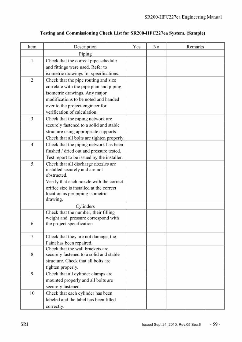
SR200-HFC227ea Engineering Manual
SRI Issued Sept 24, 2010, Rev:05 Sec.6 - 59 -
Testing and Commissioning Check List for SR200-HFC227ea System. (Sample)
Item Description Yes No Remarks
Piping
1 Check that the correct pipe schedule
and fittings were used. Refer to
isometric drawings for specifications.
2 Check that the pipe routing and size
correlate with the pipe plan and piping
isometric drawings. Any major
modifications to be noted and handed
over to the project engineer for
verification of calculation.
3 Check that the piping network are
securely fastened to a solid and stable
structure using appropriate supports.
Check that all bolts are tighten properly.
4 Check that the piping network has been
flushed / dried out and pressure tested.
Test report to be issued by the installer.
5 Check that all discharge nozzles are
installed securely and are not
obstructed.
Verify that each nozzle with the correct
orifice size is installed at the correct
location as per piping isometric
drawing.
Cylinders
6
Check that the number, their filling
weight and pressure correspond with
the project specification
7 Check that they are not damage, the
Paint has been repaired.
8
Check that the wall brackets are
securely fastened to a solid and stable
structure. Check that all bolts are
tighten properly.
9 Check that all cylinder clamps are
mounted properly and all bolts are
securely fastened.
10 Check that each cylinder has been
labeled and the label has been filled
correctly.

SR200-HFC227ea Engineering Manual
SRI Issued Sept 24, 2010, Rev:05 Sec.6 - 60 -
Item Description Yes No Remarks
11 Check that the valve outlet caps
and the plastic protective caps are
available for transport of the cylinders
for refilling.
Manifold (if used)
12 Check that the manifold arrangement is
according to drawings.
13 Check that the manifold brackets are
securely fastened to a solid and stable
structure. Check that all bolts are
tightened properly.
14 Check that the manifold is securely
fastened to the brackets.
15 Check that the manifold assembly is
securely fitted to the distribution pipe
network.
Accessories
16 Check that the discharge hose(s) has a
smooth bending, are not stretched,
compressed or kinked.
17 Check that the discharge hose(s) has
been securely fixed onto the discharge
valve outlet and at the manifold check
valve.
18 Check that pressure on each cylinder
is within the acceptable range. Refer to
Pressure -Temperature chart.
19
Check that the pressure gauge
orientation is correct, i.e. The dial
gauge face is legible.
If adjustment is required,
tighten the gauge until it stops, then
turn back a maximum of one
revolution only for correct orientation.

SR200-HFC227ea Engineering Manual
SRI Issued Sept 24, 2010, Rev:05 Sec.6 - 61 -
Item Description Yes No Remarks
20 Check for leaks at the pressure gauge
connections. Use a liquid leak tester or
soap solution. If a leak is detected,
tighten the gauge until the leak stops. If
it still leaks, the o-rings at the gauge
need to be replaced.
21 Where the pressure gauge with limit
switch is used, check for proper
installation as per item 14. Check the
function of the gauge by removing one
of the gauge and verify that the
low pressure indication at the control
panel is on. The indication should go
off once the gauge is installed back on
and the pressure is ok.
22 Check that all pneumatic actuators on
slave cylinders are installed and tighten
to a torque of 50 +0/-15 Nm.
23
Check that the pneumatic actuating
hoses are connected properly to
the pneumatic actuators on each
slave cylinders. Tighten using a spanner
until it stops.
24
Check that there is a plug installed on
the pneumatic actuator at the last slave
cylinder to close the actuating line.
WARNING :
BEFORE CARRYING OUT ANY FUNCTIONAL TESTS, MAKE SURE THAT
THE ELECTRIC SOLENOID ACTUATOR IS REMOVED FROM THE MASTER
CYLINDER AS WELL AS DISCONNECTING THE PILOT LINE HOSE
CONNECTION FROM THE SLAVE CYLINDER.
Item Description Yes No Remarks
Accessories
25 Check that the electric solenoid actuator
wiring is properly terminated.
26 Check the function of the solenoid
actuator, the pin shall extend upon
receipt of signal from control panel.

SR200-HFC227ea Engineering Manual
SRI Issued Sept 24, 2010, Rev:05 Sec.6 - 62 -
Item Description Yes No Remarks
27 Check the function of the manual
actuator if fitted. Replace the
seal tag after completion of test.
28 Check the operation of the pressure
switch (if fitted) by manually operating
it. The panel should indicate its
operation. Reset the pressure switch
after test.
Room / Enclosure
29 Verify the room sizes, compare actual
volume with project information. See
volume input used in the calculation.
30 Verify that vents / pressure relief
arrangement where required is installed
in accordance with system
requirements.
Check against results from flow
calculation information or calculations
based on the room integrity test / door
fan test.
31
Ensure that the room(s) has been
cleaned up.
General
32 Ensure that all doors into the protected
area has been provided with a warning
label / signage.
Item Description Yes No Remarks
33 Check that all manual release devices
has been provided with a warning label.
34 Ensure that the operating instructions
has / will be given.
35 Ensure that the operation and
maintenance manual has / will be given.
Commissioning Engineer's Name : Signature :
Installer / Contractor's Name : Signature :
Completion Date :
Client :

SR200-HFC227ea Engineering Manual
SRI Issued Sept 24, 2010, Rev:05 Sec.6 - 63 -
CLEAN AGENT FIRE SUPPRESSION SYSTEM
CERTIFICATE OF INSTALLATION, COMMISSIONING AND ACCEPTANCE
CLIENT :
SITE ADDRESS :
WORK UNDERTAKEN :
CONTRACT NO :
We hereby certify that in carrying out this work the methods, materials and components used comply
with the specifications and standards as listed in the contract ;
Other than the deviations listed below :-
Design Concentration : Maximum Achievable Concentration :
Fan Test Result : PASSED FAILED NOT APPLICABLE
All commissioning procedures as per checklist have been carried out.
Commissioning Engineer's Name : Signature :
Installer / Contractor's Name : Signature :
Date :
We confirm that the work has been carried out to our complete satisfaction and is accepted in good
working order. A copy of the Operation and Maintenance manual, as-built drawings and operating
instructions have been supplied and received.
Client's Representative Signature :
Name and Position :
Date :
SR200-HFC227ea Engineering Manual
SRI Issued Sept 24, 2010, Rev: 05 Sec.7 - 64 -
SR200-HFC227ea GAS FIRE SUPPRESSION SYSTEM
ENGINEERING MANUAL
7. OPERATION AND MAINTENANCE MANUAL
7.1 GENERAL
The fire fighting system shall be maintained in full operation condition at all times. The system shall
be thoroughly inspected and tested for proper operation by competent personnel at regular intervals
according to local regulations. A good maintenance program is intended to give maximum assurance
that a system will operate effectively and safely. The procedures listed in this section are the minimum
that is necessary to maintain a system. Prior to carrying out any maintenance or repair works, the
people affected by the work must be informed for them to take the necessary precautions.
7.2 SAFETY NOTICES
1. All maintenance works shall be carried out by trained personnel who are familiar with the
system and know the safety procedures. Untrained personnel could jeopardize the system
and risk damaging property and injury.
2. Prior to carrying out any testing or maintenance works, the system must be inhibited
appropriately to avoid accidental discharge of the system.
3. Before carrying out any testing or maintenance works on the system, permission or work
permits shall be obtained first and the appropriate personnel warned where necessary.
4. Adequate precautions shall be taken to avoid any unwanted process or equipment
shutdowns as a result of the testing or maintenance work carried out on the system.
5. Personnel working inside the protected area must be familiar with the operation of the
system, and the action to be taken in the event of a fire.
6. In the event of a fire, all personnel must evacuate the protected area prior to the release of
the gas system. A pre-discharge alarm must be given to allow personnel adequate time to
evacuate the area.
7. The local Fire Department should be informed of the fire. No one should enter the
protected area after a discharge other than the Fire Department personnel with breathing
apparatus to confirm that the fire is out. The protected area can then be completely
ventilated to extract the by-products of the fire.
8. In the event of an accidental discharge, all personnel should evacuate from the protected
area. Ventilate the area first before entering the protected area. Send the empty cylinders
for refilling soon as possible, if reserve bank of cylinders is available immediately connect
the charged cylinders and send the empty cylinders for refilling.
7.3 OPERATION OF THE SYSTEM
The SR200-HFC227ea clean agent fire extinguishing system utilizes the gas, Heptafluoropropane to
extinguish a fire. A detection, visual/audio alarm and control system must be incorporated into the
system for automatic operation. In the event of a fire, the detectors will sense the fire. The control
panel initiates the pre-discharge audible and visual alarms for a pre-set time. (depending on local
regulations) Thereafter, the alarms will change to discharge alarm; equipment and ventilation systems
where applicable are shutdown and the solenoid actuator on the master cylinder is energized. This
releases the gas from the master cylinder which in turn pneumatically actuates the other cylinders
connected (if any) discharging the gas into the distribution pipe work throughout the protected area.
Approximately 10 seconds after initial discharge, the gas concentration within the hazard is built up to
the design concentration, suppressing and inhibiting the fire from propagating.

SR200-HFC227ea Engineering Manual
SRI Issued Sept 24, 2010, Rev: 05 Sec.7 - 65 -
Most gaseous fire suppression systems do not cool the fuel(s) source; therefore the concentration must
be maintained for a sufficient period of time for the fuel / ignition sources to cool down.
The SR200-HFC227ea system can be manually activated by:-
a) Operation of a break glass or key switch unit linked to the control panel.
b) Operation of the manual release lever on the master cylinder (when fitted).
Operation of the manual release devices shall trigger discharge alarms, shutdowns and agent release
follow immediately.
7.4 AFTER A FIRE
A competent person must establish that the danger of fire no longer exists. If the local Fire Department
was notified of the event, they shall be able to establish this. Thereafter, completely ventilate the
protected area to remove the by-products of combustion and refresh the air within the area. The
control panel must be reset to cancel the alarms.
7.5 MAINTENANCE OF THE SYSTEM
7.5.1 MAINTENANCE
The system shall be maintained on a regular basis, at least on an annual basis or as otherwise specified
by the local authority having jurisdiction. Maintenance of the system shall include the following:-
A. Protected Area / Enclosure
1. Survey the protected area to verify that it has not changed from what the system was
designed to protect. While surveying, look for different fuels, new equipment, blocked
open doors or dampers, new penetrations or gaps which may lead to loss of the hazard
integrity, etc.
B. Discharge Nozzles
1. Check all nozzles to make certain they are in place and have not been tampered with.
Check the nozzles for corrosion or damage, and that they are not obstructed internally
or externally.
C. Distribution Pipe Network
1. Check the condition of the piping to make certain that it is properly secured in the
hangers, the brackets are not loose and all fittings are connected tightly.
D. Signage
1. Check all warning nameplates throughout the area. Ensure that they are in place,
mounted securely, readable and are not damaged.
IMPORTANT
Prior to carrying any maintenance on the system, the system should be inhibited electrically by the
control panel (if available). For multiple cylinders system with a master cylinder, the pilot line hose
must be disconnected from the slave cylinder. Thereafter, remove the electric solenoid actuator from
the master cylinder. For single cylinder systems, proceed to remove the electric solenoid actuator once
the system has been inhibited electrically if so equipped. (Ref. Fig. 7.5 - (7) for details)

SR200-HFC227ea Engineering Manual
SRI Issued Sept 24, 2010, Rev: 05 Sec.7 - 66 -
E. SR200-HFC227ea Cylinders
1. Check the cylinder bracketing. Ensure that the cylinders are secured in the brackets. Check for corrosion, damage or missing components. For the packaged type, check the
frame and plates for damage or corrosion as well as loose or missing components.
2. Check the condition of all cylinders. Check for signs of damage or corrosion and check
the cylinders' last hydro test date. (NFPA 2001 states "Cylinders continuously in
service without discharging shall be given a complete external visual inspection every
five years or more frequently if required. The visual inspection shall be in accordance
with Compressed Gas Association Pamphlet C-6, Section 3; except that the cylinders
need not be emptied or stamped while under pressure").
3. Cylinder(s) need to be removed and weight for any loss of agent. If a cylinder shows a
loss of agent quantity of more than 5%, it shall be sent for recharging.
F. Pressure gauge
1. The pressure within the cylinders should be verified using a separate calibrated test pressure gauge at least once a year. Refer to the chart no: A-01, Pressure Vs.
Temperature for cylinders filled to different ratios and pressurized with nitrogen to
25Bar @ 21oC to determine if the pressure is within the acceptable level.
2. Using an open-end spanner, slowly loosen the pressure gauge from the cylinder valve
to remove it. A 'pop' sound can be heard due to the gas escaping when the o-rings are
cleared from the gauge connection port. In case that there is gas leak from the port,
immediately screw on the test pressure gauge until the leak stops. Record the cylinder
pressure as a reference on the next pressure test. Remove the test pressure gauge and
reinstall back the pressure gauge on the cylinder valve.
3. Notice the position of the needle indicator of the pressure gauge to determine if it is in
close proximity to the actual reading of the test gauge. If the reading shows a difference
of more than 10% (+ 2.5 Bar) the gauge should be replaced.
4. If the pressure gauge with integrated pressure switch is used, verify the function of the pressure gauge by slowly removing one of the gauges from the cylinder valve. When
the gauge pressure drops below 18bar, the switch is activated and the control panel
should indicate the trouble on the system pressure.
G. Hoses
1. Check the condition of all discharge hoses and pneumatic actuating hoses at least once
a year. Ensure that all hoses are connected properly. Look for signs of structural
problems like abrasions, cracks or weather checking. Replace any suspect hose. All
hoses shall be tested every 5 years. Refer to NFPA 2001:2000 edition clause 4-3.2.2 for
detailed testing requirements.
H. Manifold (if used in multiple cylinders system)
1. Check the condition of the manifold for signs of corrosion, damage or loose parts.
2. Check the bracketing for the manifold. Ensure that the manifold is secured on the
brackets. Check for corrosion, damaged or missing parts.
I. Actuating Components
1. Electric Solenoid Actuator - The electric solenoid can be tested by 2 methods, electrical
and mechanical. For testing by electrical means, the solenoid should be tested in
conjunction with the testing of the detection and control system. Verify the operation of

SR200-HFC227ea Engineering Manual
SRI Issued Sept 24, 2010, Rev: 05 Sec.7 - 67 -
the electric solenoid actuator. A red marking can be clearly seen on the activating pin to
indicate operation of the device. Reset the solenoid actuator using the clamping device.
2. Manual / Pneumatic Actuator - For testing by mechanical means, the solenoid should
be tested in conjunction with the manual / pneumatic actuator if so equipped. To
operate the component, test it by pulling the safety pin out and push down on the lever
until the activating pin on the electric solenoid actuator is released. Reinstall the safety
pin and seal it back. Reset the electric solenoid actuator.
J. Electrical - Detection and Control
1. Check all switches on the system to assure that they will operate properly. These may
include maintenance switches, abort switches, main/reserve switches, etc. Once
completed, ensure that they are all set in the correct position.
2. Check condition of the control panel for tampering, corrosion or damage. Test the panel
at this point by referring to the panel manufacturer's operation manual.
3. Check all detectors. Make certain they are in place, clean and not damaged. If required,
check the sensitivity of each detector as per the instructions of the detector
manufacturer.
4. Check all electrical manual release stations. Make certain they are in place, that they
are not blocked or damaged. Operate each manual release system to make certain they
operate the control panel. Reset each manual release station and seal with visual
inspection seal.
5. While checking the detectors and electric manual release stations, inspect each audio /
visual alarm device. Check the alarms condition and verify that they operate properly
when energized. Reset the alarm circuit after each test.
6. Reset the entire system. This includes the control panel, all actuators, detectors, alarms,
and switches. After all components have been reset, install actuators back onto the
cylinder valves as well as the pilot actuating hose. Install visual seals where required.
K. Maintenance record
Record that the maintenance has been performed as required by the Authority Having Jurisdiction.
Inform all personnel that the maintenance has been completed and the system is back to normal.

SR200-HFC227ea Engineering Manual
SRI Issued Sept 24, 2010, Rev: 05 Sec.7 - 68 -
Fig. 7.5 - (7) - Exploded view of pilot / master cylinder connection
7.6 INSPECTION OF THE SYSTEM
An inspection is a "quick check" that a system is operable. It is intended to give reasonable assurance
that the system is fully charged and will operate. This is done by seeing that the system has not been
tampered with and that there is no obvious physical damage or any abnormal condition which can
prevent operation of the system. The value of an inspection lies in the frequency and thoroughness
with which it is conducted. Systems should be inspected at least once a month, or at intervals as
required by the local Authority Having Jurisdiction.
The following should be performed during a SR200-HFC227ea system inspection:-
1) Visually inspect the hazard area to verify that it has not changed. Check for different fuels, new equipment, blocked open doors or damper, more movable solid objects added, etc.
2) Check detectors to make certain they are in place, not damaged or coated with dirt, grease,
paint or any other contaminating substance which could affect its operation.
3) Check all audio and visual alarms for damage, dirt, corrosion, etc.
4) Check all manual release stations to assure that they have not been tampered with and are not
blocked from use.
5) Check that the piping is secured and nozzles are in place. Make certain that the nozzles are not
covered with dirt, grease or paint and that there is nothing structural blocking the discharge.
6) Visually inspect all components for signs of damage, such as disconnected or loose parts,
corrosion, twisted or dented components, missing parts, etc.
7) Check each SR200-HFC227ea cylinder pressure gauge to determine that the pressure within
the cylinders is in the operational range.

SR200-HFC227ea Engineering Manual
SRI Issued Sept 24, 2010, Rev: 05 Sec.7 - 69 -
8) Visually verify that the control panel is functioning properly.
9) Visually check the wiring of the electric solenoid actuator from the control panel to the pilot or
master cylinder to make certain it has not been disconnected.
10) Perform any other checks that may be required by the local Authority Having Jurisdiction.
11) Record that the system has been inspected and inform the relevant personnel.
Table A-01. HFC-227ea Pressure - Temperature Relations
IMPORTANT: ALL CYLINDERS SHALL BE RETURNED TO THE MANUFACTURER OR
AUTHORIZED DISTRIBUTOR FOR REFILLING OR RECHARGING. FILLING BY
UNAUTHORIZED SOURCES OR THIRD PARTIES COULD JEOPARDIZE THE
INTEGRITY OF THE SYSTEM; SAFETY OF THE PERSONNEL INVOLVED AS WELL AS
VOIDING THE WARRANTY OF THE SYSTEM IF IT IS STILL WITHIN THE COVERED
PERIOD.
7.7 INSPECTION AND MAINTENANCE CHECKLIST
Inspection and Maintenance Check List for SR200-HFC227 System. (Sample)

SR200-HFC227ea Engineering Manual
SRI Issued Sept 24, 2010, Rev: 05 Sec.7 - 70 -
Inspection and Maintenance Check List for SR200-HFC227ea System.
(Sample)
Item Description Yes No Remarks
Piping
1 Inspect /Check that the piping network
is secured. No damaged, loose, missing
or corroded components.
2 Check that all discharge nozzles are
installed securely and are not
obstructed.
Cylinders
3 Visually inspect the cylinders for signs
of damage, corrosion or abnormalities
4 Check the hydrostatic test date.
Send for testing if more than 5 years
have passed from the last test date
prior to recharging or refilling of the
cylinder.
WARNING : PRIOR TO REMOVING THE CYLINDER(S) FOR WEIGHING, ENSURE
THAT THE SYSTEM IS LOCKED OFF AND ALL ACTUATING COMPONENTS ARE
REMOVED. INSTALL THE VALVE OUTLET CAP IMMEDIATELY AFTER REMOVING
THE CYLINDER FROM THE DISTRIBUTION PIPING / MANIFOLD.
5
Check the pressure of the cylinder.
(Nominal pressure is 25 Bar @ 21oC)
If the pressure loss is more than 10%
(adjusted for ambient temperature) the
cylinder must be sent for recharging.
6
Check that each cylinder has a label
stating the contents. Note the gross
weight of the cylinder. Weight the
cylinder. If the cylinder shows an agent
loss of more than 5% it shall be sent for
recharging.
7 Check that all cylinder clamps are
mounted properly and all bolts are
securely fastened.

SR200-HFC227ea Engineering Manual
SRI Issued Sept 24, 2010, Rev: 05 Sec.7 - 71 -
8
Check that the cylinder valve outlet
caps and the plastic protective caps are
available for transport of the cylinders
for refilling.
9
Inspect the manifold for signs of
damage, corrosion or missing
components. Check that all bolts are
tighten properly and all components
are fastened securely.
10 Check that the manifold assembly is
securely fitted to the distribution pipe
network.
Accessories
11 Inspect all hoses for signs of damage,
cracks or abnormalities.
12 Check that the discharge hose(s) has
been securely fixed onto the discharge
valve outlet and at the manifold check
valve.
13 Check that pressure on each cylinder
is within the acceptable range. Refer to
Pressure -Temperature chart.
14 Check that the pressure gauge
orientation is correct, i.e.. The dial
gauge face is upright. If adjustment is
required, tighten the gauge until it
stops, then turn back a maximum of
one revolution only for correct
orientation.
15 Check for leaks at the pressure gauge
connections. Use a liquid leak tester or
soap solution. If a leak is detected,
tighten the gauge until the leak stops. If
it still leaks, the o-rings at the gauge
need to be replaced.
16 Where the pressure gauge with limit
switch is used, check for proper
installation as per item 14. Check the
function of the gauge by removing one
of the gauge and verify that the low
pressure indication at the control panel
is on. The indication should go off once
the gauge is installed back on and the
pressure is ok.

SR200-HFC227ea Engineering Manual
SRI Issued Sept 24, 2010, Rev: 05 Sec.7 - 72 -
17 Check that all pneumatic actuators on
slave cylinders are installed and tighten
on the valve securely.
18 Check that the pneumatic actuating
hoses are connected properly to the
pneumatic actuators on each slave
cylinders.
19 Check that there is a plug installed on
the pneumatic actuator at the last slave
cylinder to close the actuating line
WARNING :
BEFORE CARRYING OUT ANY FUNCTIONAL TESTS, MAKE SURE THAT
THE ELECTRIC SOLENOID ACTUATOR IS REMOVED FROM THE MASTER
CYLINDER AS WELL AS DISCONNECTING THE PILOT LINE HOSE
CONNECTION FROM THE SLAVE CYLINDER.
Item Description Yes No Remarks
Accessories
20 Check the function of the solenoid
actuator, the pin shall extend upon
receipt of signal from control panel.
21 Check the function of the manual /
pneumatic actuator if fitted. Replace the
seal tag after completion of test.
22 Check the operation of the pressure
switch (if fitted) by manually operating
it. The panel should indicate its
operation. Reset the pressure switch
after test
Room / Enclosure
23
Visually inspect the hazard area to
verify that it has not changed. Check
for different fuels, new equipment,
blocked open doors or damper, more
movable solid objects added, etc.
General
24 Check that all doors into the protected
area still have a warning label / signage.

SR200-HFC227ea Engineering Manual
SRI Issued Sept 24, 2010, Rev: 05 Sec.7 - 73 -
25 Check that all manual release devices
still have a warning label.
Inspector's Name : Signature :
Completion
Date :
Client :

SR200-HFC227ea Engineering Manual
SRI Issued Sept 24, 2010, Rev: 05 Sec.8 -74 -
SR200-HFC227ea GAS FIRE SUPPRESSION SYSTEM
ENGINEERING MANUAL
8. FILLING INSTRUCTIONS
8.1 GENERAL
The purpose of these procedures is to provide a general guideline on the filling of HFC-227ea for the
SR200-HFC227ea Gas Fire Suppression system cylinders. The intent is to have the highest guarantee
for correct filling wherever in the world a SR200-HFC227ea cylinder is filled. The filling procedures
may be adjusted accordingly for the chosen filling station, provided the stipulated requirements for
pressures and contents are complied with.
The local distributor or agent is responsible to issue these procedures to the relevant filling station. It is
the responsibility of the filling station to fill the SR200-HFC227ea cylinders according to these
procedures; attach filling tags, prepare filling lists, issue of letter of conformity, etc.
8.2 SPECIFICATIONS FOR HFC-227ea
Physical Properties of Heptafluoropropane (HFC-227ea) in NFPA 2001
Properties Value Units
Molecular Weight 170 -
Boiling Point @ 1.013 bar (absolute) -16.4 oC
Freezing Point -131 oC
Critical
Temperature 101.7 oC
Critical Pressure 29 Bar
Critical Volume 274 cc/mole
Critical Density 621 kg/m3
Specific heat, liquid @ 25oC 1.184 kJ/kg oC
Specific heat, vapour @ constant
pressure (1 atm) and 25oC 0.808 kJ/kg oC
Heat of Vaporization
at boiling point 132.6 kJ/kg
Thermal conductivity
of liquid @ 25 oC 0.069 W/m oC
Viscosity, liquid at 25oC 0.184 centipoise
Relative dielectric strength at 1 atm at
734 mm Hg, 25oC (N2 = 1.0) 2 -
Solubility of water
in agent 0.06% by weight ppm

SR200-HFC227ea Engineering Manual
SRI Issued Sept 24, 2010, Rev: 05 Sec.8 -75 -
Physical Properties of Nitrogen Gas (N2) in NFPA 2001
Properties Value Units
Molecular Mass 28.02 -
Boiling Point @ 1.013 bar (absolute) -195.8 oC
Freezing Point -210.0 oC
Critical Temperature - oC
Critical Pressure - Bar
Critical Volume - cm3/mol
Critical Density - kg/m3
Vapour Pressure 20oC - Bar
Liquid Density @ 20oC - kg/m3
Saturated Vapour Density @ 20oC - kg/m3
Specific Volume of Superheated Vapour
0.858 m3/kg at 1.013 bar and 20oC
Chemical name N2 (Nitrogen)
Specification for Nitrogen Gas (N2)
Property Requirement
Purity 99.9% by volume, min.
Moisture 50 x 10-6 by mass, max.
Oxygen 0.1% by volume, max.
NOTE: Only principal contaminants are shown. Other
measurements may include hydrocarbons, CO, NO, NO2,
CO2, etc. Most are < 20 x
10-6.
8.3 INSTALLATION OF SR200 VALVE
The SR200 valve is a pressure differential valve used for fixed fire extinguishing systems utilizing
liquefied halocarbon gases supercharged with nitrogen to a storage pressure of 25 bar at 21oC.
The valve is kept shut by the pressure within the cylinder. The valve can be open by pneumatic or
mechanical means by the use of specially designed actuating components.
a) DN33 and DN49 Valve i) Prior to fitting the DN33 or DN49 valve, ensure that the threads on both the valve and
cylinder head are free from debris and not damaged.
ii) Apply 3 layers of teflon onto the threaded end of the siphon tube. Moun the tube onto
the valve by hand until it stops.
iii) Apply or brush a small amount of silicon grease onto the cylinder collar threads. Fit the
valve onto the cylinder by hand until it stops.

SR200-HFC227ea Engineering Manual
SRI Issued Sept 24, 2010, Rev: 05 Sec.8 -76 -
NOTE: Care must be taken to use only clean cylinders without any remnants of Teflon tape,
paint particles or other contaminants. After the valves are opened and then closed, such
particles can cause leaks in the seat area and malfunction of the valve.
Install the pressure gauge onto the valve by removing the plug at the pressure gauge port. Make sure
that the port is free from debris or contaminants. Mount the pressure gauge onto the port by hand until
it stops,then turn back a MAXIMUM OF ONE REVOLUTION for correct orientation of the gauge.
.
Exploded View of SR200 Valve
8.4 FILLING METHOD
Filling of the cylinder is through the valve outlet.
a) With the tank ready for filling, a check is made to the filling instruction sheet and
the tank fill weight, time, date and fills detail record. Make sure that there is no
actuating component mounted on the valve otherwise filling cannot take place.
b) The tank is placed on a scale, secured properly with chain or cable, and the
appropriate filling adaptor attached to the valve discharge outlet.
DN33 Filling Adaptor Cap - Part No. XXX
DN49 Filling Adaptor Cap - Part No. XXX

SR200-HFC227ea Engineering Manual
SRI Issued Sept 24, 2010, Rev: 05 Sec.8 -77 -
c) Attach the fill hose line from the filling station to the filling adaptor.
d) Reset the scale to zero to compensate for the tank weight and the fill hose.
e) Switch on the pump and fill the tank to the required weight. When the correct fill is
reached, switch off the pump.
f) Attach the nitrogen supply to the line. With a separate calibrated pressure gauge
indicator adjust the nitrogen pressure to the required pressure with due allowance to
the ambient temperature. Check that the pressure gauge attached to the tank is
within + 1 bar of the fill gauge. Replace the tank gauge if it is out of this tolerance.
g) Agitate the tank to accelerate nitrogen absorption and top off the pressure
accordingly. Switch off the nitrogen supply once absorption has stopped.
h) Vent the fill hose to atmosphere. If the pressure drops to zero on the fill station
gauge within 10 seconds, the valve has closed properly.
i) Make certain the vent valve is closed when not required, to prevent contamination
to the fill line.
j) Check all ports with leak detection spray and check the valve control bore as well
for leaks.
k) Remove the fill hose and the outlet fill adaptor. Leak test the valve outlet. If there
are no leaks attach the valve outlet safety cap.
l) Reset scale and record gross weight.
m) Make certain all protective caps are in place and place tank in a holding area for
leak monitoring for at least 24 hours prior to delivery.
n) After 24 hours, leak test the valve and tank assembly once more and check that the
pressure is correct. Top up with nitrogen if necessary.
8.5 CYLILNDER MAINTENANCE
Initial Filling
1) Cylinders shall be new or have been pressure tested according to local requirements. The date
and marking of the pressure test shall be clearly stamped on the cylinders as required by local
regulations.
2) The SR200 cylinders are factory painted to Signal Red (RAL3000) colour. For other colour requirements according to local regulations, the cylinders shall be painted first prior to filling.
3) The cylinders must be cleaned and dried out internally prior to fitting of valve. This is to avoid
any contaminants from lodging onto the valve seat after opening and closing of the valve
which may cause the valve to leak or malfunction.
4) Filled cylinders to be provided with a transport / filled tag indicating the contents and the pressure.
Recharge / Refill after discharge
1) A residual pressure of 3 + 2 Bar will remain in the cylinder after discharge. For safety reasons,
the valve outlet safety cap must be fitted to avoid an accidental escape of this residual gas prior
to refilling of the cylinder.
2) Wherever required, the cylinders shall be pressure tested and stamped accordingly. NFPA 2001
states that cylinders that have discharged or leaked need to be pressure tested again if more
than 5 years have passed since the last pressure test. Cylinders that are continuous in service
need not be tested but must be inspected. They shall be required to discharge and pressure test
again after 10 years have passed from the last test date.
3) Where necessary, the cylinders shall be refurbished and repainted again prior to refilling.
4) Recharged cylinders to be provided with a transport / service tag indicating the contents and the pressure.

SR200-HFC227ea Engineering Manual
SRI Issued Sept 24, 2010, Rev: 05 Sec.8 -78 -
8.6 FILLING CHECK LIST
Item Description Checked Comments
1 List the cylinder serial number on filling list
(refer to sample on item 8.7)
2 Make sure that there are no actuating components attached to
the valve and that there is no foreign matter / debris on the
Valve outlet prior to connecting the filling hose.
3 Fill the liquefied gas to the required weight.
4 Super pressurize with dry nitrogen to the required pressure.
(25 Bar @ 21oC) Refer to chart 8.7-1.
5 Agitate the cylinder. Top up with nitrogen if necessary.
6 Check for leaks on the valve. No leaks are accepted.
7 Screw on the valve outlet safety cap.
8 Fit the plastic protective cap onto the valve.
9 Attach the cylinder label with relevant details as required.
10 Secure cylinder(s) on transport cage or pallets.
11 Ship to receiver or site as per order.
12 Issue the filling list.
13 Issue the letter of conformity to the client or purchaser.

SR200-HFC227ea Engineering Manual
SRI Issued Sept 24, 2010, Rev: 05 Sec.8 -79 -
Chart 8.6 -1. HFC-227, Pressure - Temperature Relations

SR200-HFC227ea Engineering Manual
SRI Issued Sept 24, 2010, Rev: 05 Sec.8 -80 -
8.7 FILLING LIST
The filling station is required to fill in the Filling List and a copy to be issue to the client or purchaser.
A copy is to be included in the shipment. A sample of the list is as follows:-
Filling List No. : Purchase Order No.:
Client :
Cylinder S / N : Cylinder Vol : Filled N2 Date Filler's
L to : of Signature
25 Bar Filling
As well as the filling list, the filling station shall issue a letter of conformity for every batch of
cylinders filled.

SR200-HFC227ea Engineering Manual
SRI Issued Sept 24, 2010, Rev: 05 Sec.9 - 82 -
SR200-HFC227ea GAS FIRE SUPPRESSION SYSTEM
ENGINEERING MANUAL
9. SAFETY INSTRUCTIONS
9.1 GENERAL
The SR200-HFC227 cylinder is filled with the required weight of HFC-227ea gas and super-
pressurized with nitrogen to 25 bar at a reference temperature of 21oC. With such a high pressure, if
the cylinder valve were to operate, or if the valve was accidentally sheared off without the cylinder
properly secured, the thrust force produced by the gas is sufficient to propel the cylinder with
consequent risk to life and property. As such, safety precautions must be adhered to in the handling of
the SR200-HFC227 cylinders.
Some safety precautions to follow are: -
1) The valve outlet cap shall always be screwed onto the cylinder valve whenever the cylinder is moved, being loaded or unloaded.
2) Always use suitable lifting gear, (forklift, truck or hoist) when loading or unloading cylinders. Do not offload the cylinders by dropping them to the ground.
3) Use a suitable cylinder trolley to move the cylinders.
4) At site, if the cylinders are not to be installed immediately, store preferably in a place where
they will not be damaged.
5) Do not remove the valve outlet cap from the cylinder unless the cylinder are securely held in
position by its clamps.
6) Never attempt to remove a SR200 valve from a pressurized cylinder.
7) Do not use extreme force (hammers, long levers, pipe wrench, etc.) on any part of the valve or
actuating components.
8) Cylinders, valves, and actuating components SHALL NOT BE drilled, brazed, welded,
machined or stamped. The only permitted processes are cleaning and painting of the cylinder
and not the valve.
9) In the event of any abnormalities such as jammed or deformed valves, cracks or other apparent
weaknesses, keep away and inform the appropriate engineer.
10) Heavy protective gloves (preferably textile or leather) should be worn at all times for the
manual handling of cylinders to minimize the risk of injury. When the cylinders have
discharged, they become very cold and condensation occurs. The cylinders will be difficult to
handle with bare hands due to the wet surface of the cylinders.
11) Safety footwear shall always be worn at all times.
12) Handle all cylinders as if they were fully charged.

SR200-HFC227ea Engineering Manual
SRI Issued Sept 24, 2010, Rev: 05 Sec.9 - 83 -
13) When the SR200-HFC227ea valve has been actuated, the valve will remain open until the
pressure in the container falls below 3 + 2 bar, the valve closes automatically. Consequently, a
residual pressure remains in the cylinder. To avoid the danger of this residual gas escaping in
the event of an accidental triggering, ALWAYS screw on the valve outlet safety cap onto the
valve when the cylinder is removed for maintenance.
14) When the container is fully charged, the control valve bore stem at the top of the SR200-
HFC227ea valve can be seen jutting out. Do not attempt to depress this control valve stem as
this will cause the valve to open and discharge its contents. The valve is fitted with a plastic
protective cap from the factory. Leave the cap on until you are ready to install the actuating
components. Install this cap back on whenever the cylinder is removed for maintenance.
15) All actuating components, electric solenoid actuator, manual / pneumatic actuator, pneumatic
actuators, etc. shall be fitted and tighten by hand onto the SR200 valve until it stops.
Alternatively use a torque spanner and tighten to a torque of 50 +0/-15 Nm.
16) The SR200 valve is a simple valve designed for a long service life and requires nearly no
maintenance at all. After operation of the valve, there is no replacement of parts required.
However, care must be taken to ensure that no foreign matter, particles or dust enters the
cylinders or accumulates at the control valve bore. If contaminants were in the cylinders, they
could cause damage to the valve seat when opening and closing of the valve occurs. Therefore,
care must be taken to ensure that the cylinders are internally cleaned prior to fitting or refitting
of the valve. All residual or excess teflon tape must be removed from both the cylinder and
valve threads. Accumulation of dirt or foreign matter at the control valve bore may cause a
malfunction of the valve. Therefore, if an actuating component is not fitted to the valve the
plastic protective cap must always be fitted on the valve.

SR200-HFC227ea Engineering Manual
SRI Issued Sept 24, 2010, Rev: 05 Sec.10 - 84 -
SR200-HFC227ea GAS FIRE SUPPRESSION SYSTEM
ENGINEERING MANUAL
10. DETECTION AND CONTROL
10.1 GENERAL
The SR200-HFC227ea gas fire suppression system must be used in conjunction with a detection and
control system in order for the extinguishing system to operate automatically. Some issues must be
addressed before deciding on the best detection system. They are:-
a) the speed of detection required
b) what phenomenon to detect, e.g. Smoke, heat, flame, gas, fuel mist, etc.
c) Relative acceptability of unwanted alarms
d) Cost effectiveness
Generally, all gaseous extinguishing system requires a detection and control system to operate
automatically. Detectors are needed to sense the fire, while the control system would give the signal to
all visual & audio alarms, shutdown auxiliary equipment, and activate the suppression system.
10.2 DETECTION SPEED
A gas extinguishing system's speed of extinguishment is usually more dependant on the response time
of the detection system, rather than the discharge time of the gas. There is a wide variety of detection
and control technologies available in order to cover the different types of fire risks. However, the
technologies differ greatly in cost, and as such it is important to select a system that offers the client
the optimum and cost-effective fire protection system.
10.3 TYPE OF DETECTORS
The type of detectors commonly used in gaseous fire extinguishing systems are smoke detectors and
heat detectors. For certain special hazards, flame detectors and gas detectors are used.
Smoke detectors are available in several types, ionization, optical, aspirated and air aspiration system.
The first two types are widely available at reasonable prices and are commonly used. Aspirated type
are slightly more expensive but their response time is faster. For an even faster response time an air
aspiration system can be used. However, they are much more expensive and are more suited for clean
room environments. Generally, the more sensitive the detectors, the more prone they are to false
alarms.
Heat detectors are normally available in 3 types, rate of rise (ROR), fixed temperature or a
combination of both ROR and fixed temperature. Heat detectors are less prone to false
alarms and are cheaper compared to smoke detectors. However, in most cases, a fire may
well be underway before the heat detector operates. In high risks or sensitive areas using a
gaseous extinguishing system, the delay of a heat detector would cause fire damages which
might be unacceptable to the client.
SR200-HFC227ea Engineering Manual
SRI Issued Sept 24, 2010, Rev: 05 Sec.10 - 85 -
Flame detectors are employed where flammable liquids or powders are present since fires spread very
rapidly. Flame detectors are available in 2 types, ultra-violet (UV) and infrared (IR) flame detector.
UV flame detector respond faster compared to the IR flame detector. UV detectors can be blinded by
dirt or grease while IR detectors can be blinded by water. Consideration must be given to incorporate a
monitoring system on these detectors to give a fault alarm if they are blinded.
10.4 DETECTOR SPACING
Currently, there is no one internationally recognized standard for detector spacing therefore the
detector requirements shall be based on the respective countries' standard or as required by the local
authority having jurisdiction.
There is a general consensus that while the detectors used for fire alarms can be installed at its
maximum area coverage, those used for triggering gas suppression systems should be reduced or
halved. This is because detectors installed at the maximum approved spacing for fire alarm use could
result in excessive delay in extinguishant release, especially when more than one detection device is
required to be in alarm before automatic actuation results.
10.5 DETECTOR LOCATION
Detectors should be placed in a protected enclosure with the following aims:
1) to give the detectors the best chance to detect a fire quickly, and
2) to reduce the risk that the detectors give a false alarm.
To make sure that the detectors can sense a fire, do:-
1) locate them at least 1 m from all obstructions.
2) assure a free passage of smoke to the detectors. Install detectors in a cable floor as well as the main room if the cable floor should also be protected.
3) evaluate the impact of the ventilation systems on detectors; they sometimes either prevent the smoke reaching the detection chamber or else contaminate detectors in air currents with dust.
Conventional detectors should be installed in crossed zones, where each zone is made up of detectors
installed diagonally to each other. In any case a minimum of two detectors must operate before the gas
is released automatically.
10.6 TYPICAL SEQUENCE
The following is a typical sequence of events (details may vary according to local practice or
regulations):-
a) A detector goes into alarm
b) Visual and audible pre-alarm is given
c) The ventilation system is automatically switched off

SR200-HFC227ea Engineering Manual
SRI Issued Sept 24, 2010, Rev: 05 Sec.10 - 86 -
d) A second detector goes into alarm, confirming the fire condition.
e) Visual and audible fire alarm is given and the time delay is started.
f) Any automatic closing of doors or openings is initiated.
g) After the preset delay, a signal is sent to the electric actuator to release the gas.
h) A visual alarm is given, indicating the release of the gas.
Other possible events which could alter this sequence are:
a) The release signal may be manual; it will have the same effect as the second (confirmation) detection signal.
b) There might be an Abort or Hold switch to prevent a discharge, for example when people are present in the enclosure.
All control panels normally would have a facility for adjusting the time delay but the range may vary
from 0 - 60s to 120s depending on the local requirements.
It is not the intention of this section to recommend any particular makes of detectors and control
systems since each countries have their own standards and regulations. As such, the proposed
detection and control system shall have the approval of the Local Authority having Jurisdiction.