
CLASSIFICATION - catalogimages.wiley.com · Liquid propellant rocket engines use liquid propellants...
27
CHAPTER 1 CLASSIFICATION The word propulsion comes from the Latin propulsus , which is the past participle of the verb propellere , meaning to drive away. In a broad sense propulsion is the act of changing the motion of a body. Propulsion mechanisms provide a force that moves bodies that are initially at rest, changes a velocity, or overcomes retarding forces when a body is propelled through a medium. Jet propulsion is a means of locomotion whereby a reaction force is imparted to a device by the momentum of ejected matter. Rocket propulsion is a class of jet propulsion that produces thrust by ejecting matter stored in a flying vehicle called the propellant. Duct propulsion is a class of jet propulsion and includes turbojets and ramjets; these engines are also com- monly called air-breathing engines. Duct propulsion devices utilize mostly the surrounding medium as the “working fluid,” together with some vehicle-stored fuel. Combinations of rockets and duct propulsion devices can be attractive for some narrow applications and one is briefly described in this chapter. The energy source most useful to rocket propulsion is chemical combustion . Energy can also be supplied by solar radiation and, in the past, also by nuclear reaction . Accordingly, the various propulsion devices can be divided into chem- ical propulsion, nuclear propulsion , and solar propulsion . Table 1–1 lists many of the important propulsion concepts according to their energy source and type of propellant or working fluid. Radiation energy can originate from sources other than the sun and theoretically can cover the transmission of energy by microwave and laser beams, electromagnetic waves, and electrons, protons, and other par- ticle beams from a transmitter to a flying receiver. Nuclear energy is associated with the transformations of atomic particles within the nucleus of atoms and usually is created by fission or fusion. Other energy sources, both internal (in the vehicle) and external, can be considered. The energy form found in the output 1 COPYRIGHTED MATERIAL
Transcript of CLASSIFICATION - catalogimages.wiley.com · Liquid propellant rocket engines use liquid propellants...
CHAPTER 1
CLASSIFICATION
The word propulsion comes from the Latin propulsus , which is the past participleof the verb propellere, meaning to drive away. In a broad sense propulsion is theact of changing the motion of a body. Propulsion mechanisms provide a forcethat moves bodies that are initially at rest, changes a velocity, or overcomesretarding forces when a body is propelled through a medium. Jet propulsion isa means of locomotion whereby a reaction force is imparted to a device by themomentum of ejected matter.
Rocket propulsion is a class of jet propulsion that produces thrust by ejectingmatter stored in a flying vehicle called the propellant. Duct propulsion is a classof jet propulsion and includes turbojets and ramjets; these engines are also com-monly called air-breathing engines. Duct propulsion devices utilize mostly thesurrounding medium as the “working fluid,” together with some vehicle-storedfuel. Combinations of rockets and duct propulsion devices can be attractive forsome narrow applications and one is briefly described in this chapter.
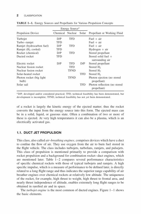
The energy source most useful to rocket propulsion is chemical combustion .Energy can also be supplied by solar radiation and, in the past, also by nuclearreaction . Accordingly, the various propulsion devices can be divided into chem-ical propulsion, nuclear propulsion , and solar propulsion . Table 1–1 lists manyof the important propulsion concepts according to their energy source and typeof propellant or working fluid. Radiation energy can originate from sources otherthan the sun and theoretically can cover the transmission of energy by microwaveand laser beams, electromagnetic waves, and electrons, protons, and other par-ticle beams from a transmitter to a flying receiver. Nuclear energy is associatedwith the transformations of atomic particles within the nucleus of atoms andusually is created by fission or fusion. Other energy sources, both internal (in thevehicle) and external, can be considered. The energy form found in the output
1
COPYRIG
HTED M
ATERIAL
2 CLASSIFICATION
TABLE 1–1. Energy Sources and Propellants for Various Propulsion Concepts
Energy Sourcea
Propulsion Device Chemical Nuclear Solar Propellant or Working Fluid
Turbojet D/P TFD Fuel + airTurbo–ramjet TFD Fuel + airRamjet (hydrocarbon fuel) D/P TFD Fuel + airRamjet (H2 cooled) TFD Hydrogen + airRocket (chemical) D/P TFD Stored propellantDucted rocket TFD Stored solid fuel +
surrounding airElectric rocket D/P TFD D/P Stored propellantNuclear fission rocket TFD Stored H2
Nuclear fusion rocket TFND Stored H2
Solar-heated rocket TFD Stored H2
Photon rocket (big lightbulb)
TFND Photon ejection (no storedpropellant)
Solar sail TFD Photon reflection (no storedpropellant)
a D/P, developed and/or considered practical; TFD, technical feasibility has been demonstrated, butdevelopment is incomplete; TFND, technical feasibility has not yet been demonstrated.
of a rocket is largely the kinetic energy of the ejected matter; thus the rocketconverts the input from the energy source into this form. The ejected mass canbe in a solid, liquid, or gaseous state. Often a combination of two or more ofthese is ejected. At very high temperatures it can also be a plasma, which is anelectrically activated gas.
1.1. DUCT JET PROPULSION
This class, also called air-breathing engines , comprises devices which have a ductto confine the flow of air. They use oxygen from the air to burn fuel stored inthe flight vehicle. The class includes turbojets, turbofans, ramjets, and pulsejets.This class of propulsion is mentioned primarily to provide a comparison withrocket propulsion and a background for combination rocket–duct engines, whichare mentioned later. Table 1–2 compares several performance characteristicsof specific chemical rockets with those of typical turbojets and ramjets. A highspecific impulse, which is a measure of performance to be defined later, is directlyrelated to a long flight range and thus indicates the superior range capability of airbreather engines over chemical rockets at relatively low altitude. The uniquenessof the rocket, for example, high thrust to weight, high thrust to frontal area, andnearly thrust independence of altitude, enables extremely long flight ranges to beobtained in rarefied air and in space.
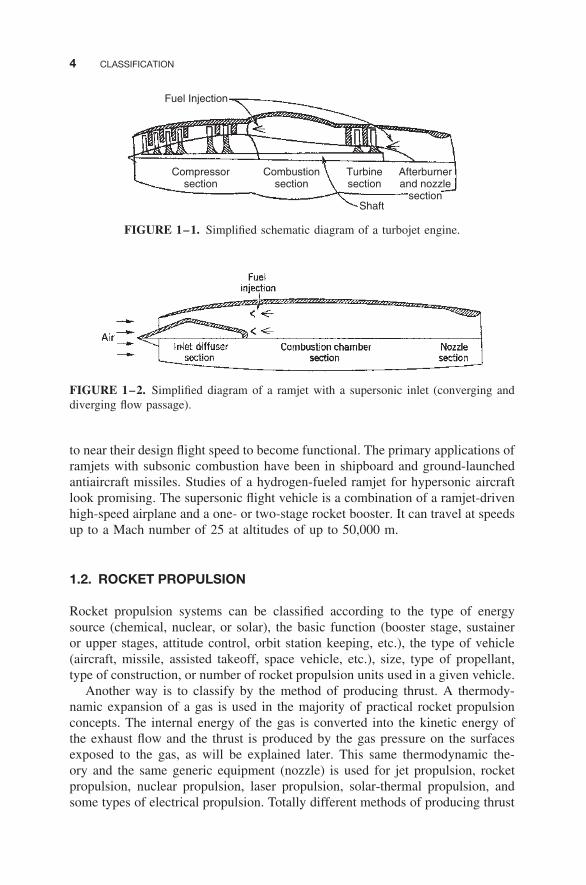
The turbojet engine is the most common of ducted engines. Figure 1–1 showsthe basic elements.

1.1. DUCT JET PROPULSION 3
TABLE 1–2. Comparison of Several Characteristics of a Typical Chemical Rocket andTwo-Duct Propulsion Systems
ChemicalRocket Engine
or RocketFeature Motor Turbojet Engine Ramjet Engine
Thrust-to-weight ratio,typical
75:1 5:1, turbojet andafterburner
7:1 at Mach 3 at30,000 ft
Specific fuel consumption(pounds of propellant orfuel per hour per poundof thrust)a
8–14 0.5–1.5 2.3–3.5
Specific thrust (pounds ofthrust per square footfrontal area)b
5000–25,000 2500 (low Mach atsea level)
2700 (Mach 2 at sealevel)
Thrust change with altitude Slight increase Decreases DecreasesThrust vs. flight speed Nearly constant Increases with
speedIncreases with speed
Thrust vs. air temperature Constant Decreases withtemperature
Decreases withtemperature
Flight speed vs. exhaustvelocity
Unrelated,flight speedcan begreater
Flight speedalways less thanexhaust velocity
Flight speed alwaysless than exhaustvelocity
Altitude limitation None; suited tospace travel
14,000–17,000 m 20,000 m at Mach 3
30,000 m at Mach 545,000 m at Mach 12
Specific impulse, typicalc
(thrust force per unitpropellant or fuel weightflow per second)
270 sec 1600 sec 1400 sec
a Multiply by 0.102 to convert to kg/(hr-N).bMultiply by 47.9 to convert to N/m2
cSpecific impulse is a performance parameter and is defined in Chapter 2.
At supersonic flight speeds above Mach 2, the ramjet engine (a pure ductengine) becomes attractive for flight within the atmosphere. Thrust is producedby increasing the momentum of the air as it passes through the ramjet, basically asis accomplished in the turbojet and turbofan engines but without compressors orturbines. Figure 1–2 shows the basic components of one type of ramjet. Ramjetswith subsonic combustion and hydrocarbon fuel have an upper speed limit ofapproximately Mach 5; hydrogen fuel, with hydrogen cooling, raises this to atleast Mach 16. Ramjets with supersonic combustion are known as scramjets andhave flown in experimental vehicles. All ramjets depend on rocket boosters orsome other method (such as being launched from an aircraft) for being accelerated
4 CLASSIFICATION
Fuel Injection
Compressorsection
Combustionsection
Turbinesection
Afterburnerand nozzle
sectionShaft
FIGURE 1–1. Simplified schematic diagram of a turbojet engine.
FIGURE 1–2. Simplified diagram of a ramjet with a supersonic inlet (converging anddiverging flow passage).
to near their design flight speed to become functional. The primary applications oframjets with subsonic combustion have been in shipboard and ground-launchedantiaircraft missiles. Studies of a hydrogen-fueled ramjet for hypersonic aircraftlook promising. The supersonic flight vehicle is a combination of a ramjet-drivenhigh-speed airplane and a one- or two-stage rocket booster. It can travel at speedsup to a Mach number of 25 at altitudes of up to 50,000 m.
1.2. ROCKET PROPULSION
Rocket propulsion systems can be classified according to the type of energysource (chemical, nuclear, or solar), the basic function (booster stage, sustaineror upper stages, attitude control, orbit station keeping, etc.), the type of vehicle(aircraft, missile, assisted takeoff, space vehicle, etc.), size, type of propellant,type of construction, or number of rocket propulsion units used in a given vehicle.
Another way is to classify by the method of producing thrust. A thermody-namic expansion of a gas is used in the majority of practical rocket propulsionconcepts. The internal energy of the gas is converted into the kinetic energy ofthe exhaust flow and the thrust is produced by the gas pressure on the surfacesexposed to the gas, as will be explained later. This same thermodynamic the-ory and the same generic equipment (nozzle) is used for jet propulsion, rocketpropulsion, nuclear propulsion, laser propulsion, solar-thermal propulsion, andsome types of electrical propulsion. Totally different methods of producing thrust
1.2. ROCKET PROPULSION 5
are used in other types of electric propulsion or by using a pendulum in a gravitygradient. As described below, these electric systems use magnetic and/or electricfields to accelerate electrically charged molecules or atoms at very low densities.It is also possible to obtain a very small acceleration by taking advantage of thedifference in gravitational attraction as a function of altitude, but this method isnot explained in this book.
The Chinese developed and used solid propellant in rocket missiles over 800years ago, and military bombardment rockets were used frequently in the eigh-teenth and nineteenth centuries. However, the significant developments of rocketpropulsion took place in the twentieth century. Early pioneers included the Rus-sian Konstantin E. Ziolkowsky, who is credited with the fundamental rocketflight equation and his 1903 proposals to build rocket vehicles. The GermanHermann Oberth developed a more detailed mathematical theory; he proposedmultistage vehicles for space flight and fuel-cooled thrust chambers. The Amer-ican Robert H. Goddard is credited with the first flight using a liquid propellantrocket engine in 1926. An early book on the subject was written by the Vienneseengineer Eugen Sanger. For rocket history see Refs. 1–1 to 1–8.
Chemical Rocket Propulsion
The energy from a high-pressure combustion reaction of propellant chemicals,usually a fuel and an oxidizing chemical, permits the heating of reaction productgases to very high temperatures (2500 to 4100◦C or 4500 to 7400◦F). Thesegases subsequently are expanded in a nozzle and accelerated to high velocities(1800 to 4300 m/sec or 5900 to 14,100 ft/sec). Since these gas temperatures areabout twice the melting point of steel, it is necessary to cool or insulate all thesurfaces that are exposed to the hot gases. According to the physical state ofthe propellant, there are several different classes of chemical rocket propulsiondevices.
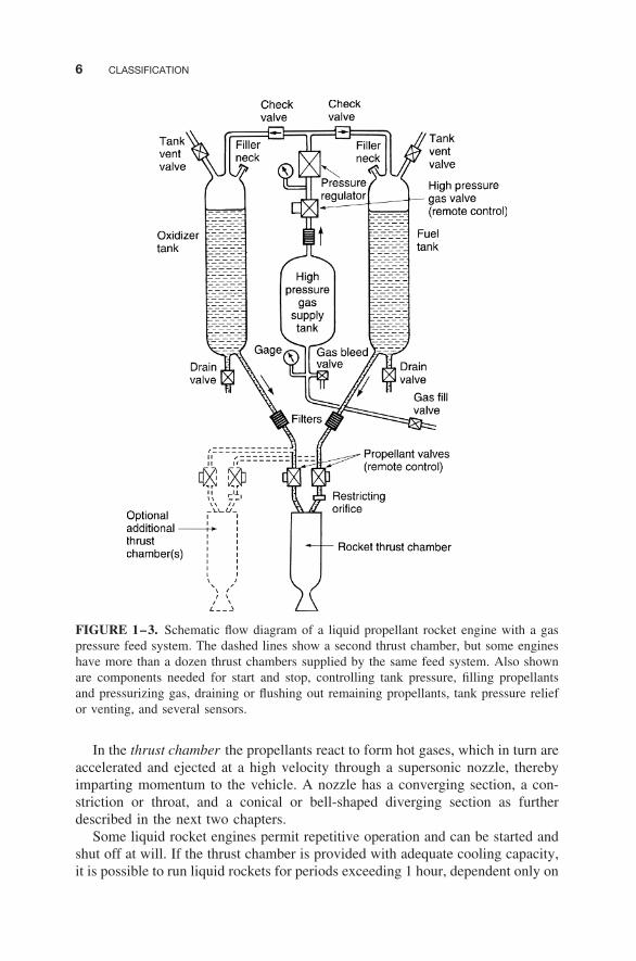
Liquid propellant rocket engines use liquid propellants that are fed under pres-sure from tanks into a thrust chamber.∗ A typical pressure-fed liquid propellantrocket engine system is schematically shown in Fig. 1–3. The liquid bipropellantconsists of a liquid oxidizer (e.g., liquid oxygen) and a liquid fuel (e.g., kerosene).A monopropellant is a single liquid that contains both oxidizing and fuel species;it decomposes into hot gas when properly catalyzed. A large turbopump-fed liq-uid propellant rocket engine is shown in Fig. 1–4. Gas pressure feed systems areused mostly on low thrust, low total energy propulsion systems, such as thoseused for attitude control of flying vehicles, often with more than one thrust cham-ber per engine. Pump-fed liquid rocket systems are used typically in applicationswith larger amounts of propellants and higher thrusts, such as in space launchvehicles. See Refs. 1–1 to 1–6.
∗The term thrust chamber , used for the assembly of the injector, nozzle, and chamber, is preferredby several official agencies and therefore has been used in this book. For small spacecraft controlrockets the term thruster (a small thrust chamber) is commonly used, and this term will be used insome sections of this book.
6 CLASSIFICATION
FIGURE 1–3. Schematic flow diagram of a liquid propellant rocket engine with a gaspressure feed system. The dashed lines show a second thrust chamber, but some engineshave more than a dozen thrust chambers supplied by the same feed system. Also shownare components needed for start and stop, controlling tank pressure, filling propellantsand pressurizing gas, draining or flushing out remaining propellants, tank pressure reliefor venting, and several sensors.
In the thrust chamber the propellants react to form hot gases, which in turn areaccelerated and ejected at a high velocity through a supersonic nozzle, therebyimparting momentum to the vehicle. A nozzle has a converging section, a con-striction or throat, and a conical or bell-shaped diverging section as furtherdescribed in the next two chapters.
Some liquid rocket engines permit repetitive operation and can be started andshut off at will. If the thrust chamber is provided with adequate cooling capacity,it is possible to run liquid rockets for periods exceeding 1 hour, dependent only on
1.2. ROCKET PROPULSION 7
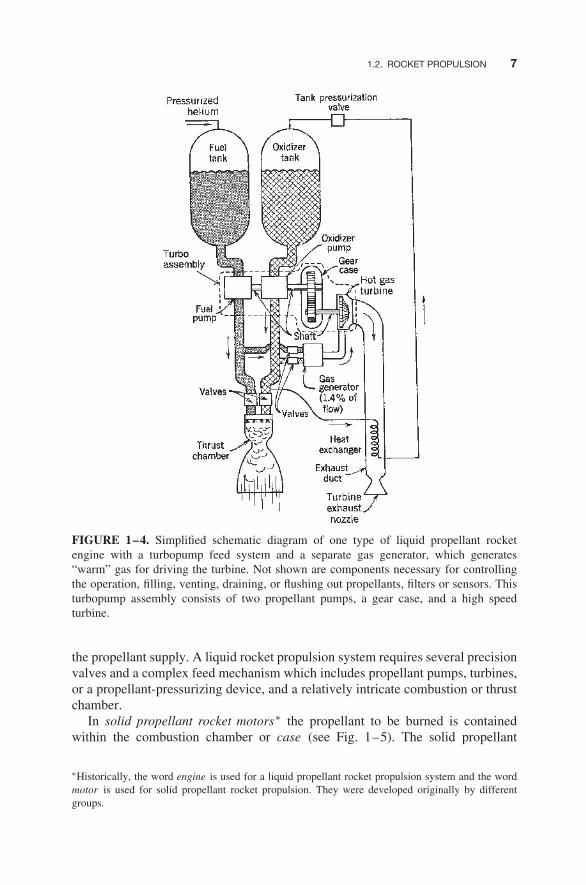
FIGURE 1–4. Simplified schematic diagram of one type of liquid propellant rocketengine with a turbopump feed system and a separate gas generator, which generates“warm” gas for driving the turbine. Not shown are components necessary for controllingthe operation, filling, venting, draining, or flushing out propellants, filters or sensors. Thisturbopump assembly consists of two propellant pumps, a gear case, and a high speedturbine.
the propellant supply. A liquid rocket propulsion system requires several precisionvalves and a complex feed mechanism which includes propellant pumps, turbines,or a propellant-pressurizing device, and a relatively intricate combustion or thrustchamber.
In solid propellant rocket motors∗ the propellant to be burned is containedwithin the combustion chamber or case (see Fig. 1–5). The solid propellant
∗Historically, the word engine is used for a liquid propellant rocket propulsion system and the wordmotor is used for solid propellant rocket propulsion. They were developed originally by differentgroups.
8 CLASSIFICATION
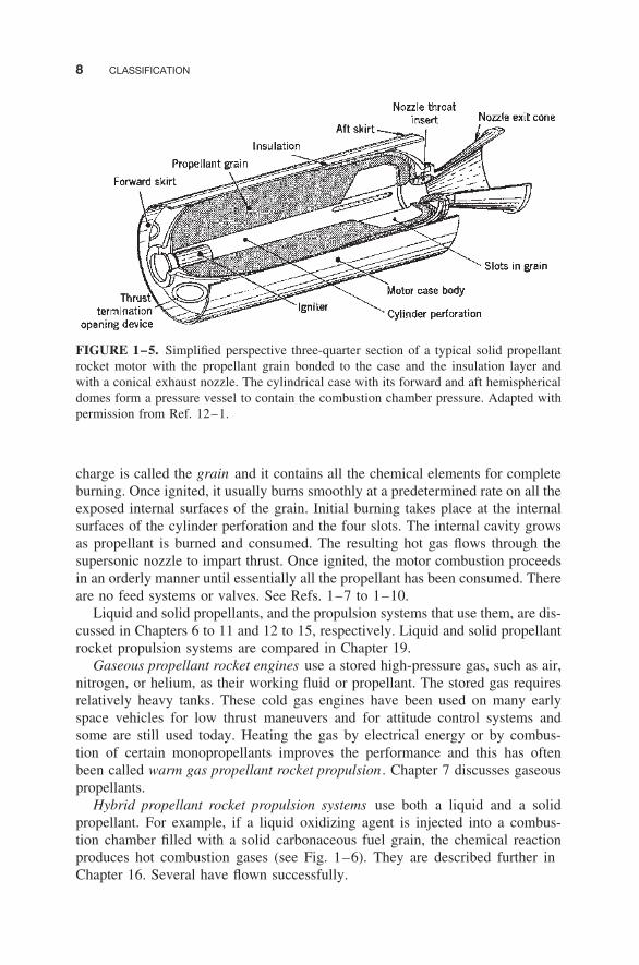
FIGURE 1–5. Simplified perspective three-quarter section of a typical solid propellantrocket motor with the propellant grain bonded to the case and the insulation layer andwith a conical exhaust nozzle. The cylindrical case with its forward and aft hemisphericaldomes form a pressure vessel to contain the combustion chamber pressure. Adapted withpermission from Ref. 12–1.
charge is called the grain and it contains all the chemical elements for completeburning. Once ignited, it usually burns smoothly at a predetermined rate on all theexposed internal surfaces of the grain. Initial burning takes place at the internalsurfaces of the cylinder perforation and the four slots. The internal cavity growsas propellant is burned and consumed. The resulting hot gas flows through thesupersonic nozzle to impart thrust. Once ignited, the motor combustion proceedsin an orderly manner until essentially all the propellant has been consumed. Thereare no feed systems or valves. See Refs. 1–7 to 1–10.
Liquid and solid propellants, and the propulsion systems that use them, are dis-cussed in Chapters 6 to 11 and 12 to 15, respectively. Liquid and solid propellantrocket propulsion systems are compared in Chapter 19.
Gaseous propellant rocket engines use a stored high-pressure gas, such as air,nitrogen, or helium, as their working fluid or propellant. The stored gas requiresrelatively heavy tanks. These cold gas engines have been used on many earlyspace vehicles for low thrust maneuvers and for attitude control systems andsome are still used today. Heating the gas by electrical energy or by combus-tion of certain monopropellants improves the performance and this has oftenbeen called warm gas propellant rocket propulsion . Chapter 7 discusses gaseouspropellants.
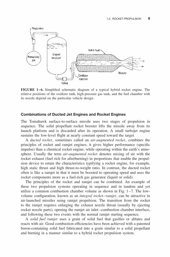
Hybrid propellant rocket propulsion systems use both a liquid and a solidpropellant. For example, if a liquid oxidizing agent is injected into a combus-tion chamber filled with a solid carbonaceous fuel grain, the chemical reactionproduces hot combustion gases (see Fig. 1–6). They are described further inChapter 16. Several have flown successfully.
1.2. ROCKET PROPULSION 9
FIGURE 1–6. Simplified schematic diagram of a typical hybrid rocket engine. Therelative positions of the oxidizer tank, high-pressure gas tank, and the fuel chamber withits nozzle depend on the particular vehicle design.
Combinations of Ducted Jet Engines and Rocket Engines
The Tomahawk surface-to-surface missile uses two stages of propulsion insequence. The solid propellant rocket booster lifts the missile away from itslaunch platform and is discarded after its operation. A small turbojet enginesustains the low-level flight at nearly constant speed toward the target.
A ducted rocket , sometimes called an air-augmented rocket , combines theprinciples of rocket and ramjet engines; it gives higher performance (specificimpulse) than a chemical rocket engine, while operating within the earth’s atmo-sphere. Usually the term air-augmented rocket denotes mixing of air with therocket exhaust (fuel rich for afterburning) in proportions that enable the propul-sion device to retain the characteristics typifying a rocket engine, for example,high static thrust and high thrust-to-weight ratio. In contrast, the ducted rocketoften is like a ramjet in that it must be boosted to operating speed and uses therocket components more as a fuel-rich gas generator (liquid or solid).
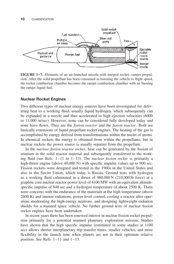
The principles of the rocket and ramjet can be combined. An example ofthese two propulsion systems operating in sequence and in tandem and yetutilize a common combustion chamber volume as shown in Fig. 1–7. The low-volume configuration, known as an integral rocket–ramjet , can be attractive inair-launched missiles using ramjet propulsion. The transition from the rocketto the ramjet requires enlarging the exhaust nozzle throat (usually by ejectingrocket nozzle parts), opening the ramjet air inlet–combustion chamber interface,and following these two events with the normal ramjet starting sequence.
A solid fuel ramjet uses a grain of solid fuel that gasifies or ablates andreacts with air. Good combustion efficiencies have been achieved with a patentedboron-containing solid fuel fabricated into a grain similar to a solid propellantand burning in a manner similar to a hybrid rocket propulsion system.
10 CLASSIFICATION
FIGURE 1–7. Elements of an air-launched missile with integral rocket–ramjet propul-sion. After the solid propellant has been consumed in boosting the vehicle to flight speed,the rocket combustion chamber becomes the ramjet combustion chamber with air burningthe ramjet liquid fuel.
Nuclear Rocket Engines
Two different types of nuclear energy sources have been investigated for deliv-ering heat to a working fluid, usually liquid hydrogen, which subsequently canbe expanded in a nozzle and thus accelerated to high ejection velocities (6000to 11,000 m/sec). However, none can be considered fully developed today andnone have flown. They are the fission reactor and the fusion reactor . Both arebasically extensions of liquid propellant rocket engines. The heating of the gas isaccomplished by energy derived from transformations within the nuclei of atoms.In chemical rockets the energy is obtained from within the propellants, but innuclear rockets the power source is usually separate from the propellant.
In the nuclear fission reactor rocket , heat can be generated by the fission ofuranium in the solid reactor material and subsequently transferred to the work-ing fluid (see Refs. 1–11 to 1–13). The nuclear fission rocket is primarily ahigh-thrust engine (above 40,000 N) with specific impulse values up to 900 sec.Fission rockets were designed and tested in the 1960s in the United States andalso in the Soviet Union, which today is Russia. Ground tests with hydrogenas a working fluid culminated in a thrust of 980,000 N (210,000 lb force) at agraphite core nuclear reactor power level of 4100 MW with an equivalent altitude-specific impulse of 848 sec and a hydrogen temperature of about 2500 K. Therewere concerns with the endurance of the materials at the high temperature (above2600 K) and intense radiations, power level control, cooling a reactor after oper-ation, moderating the high-energy neutrons, and designing lightweight radiationshields for a manned space vehicle. No further ground tests of nuclear fissionrocket engines have been undertaken.
In recent years there has been renewed interest in nuclear fission rocket propul-sion primarily for a potential manned planetary exploration mission. Studieshave shown that the high specific impulse (estimated in some studies at 1100sec) allows shorter interplanetary trip transfer times, smaller vehicles, and moreflexibility in the launch time when planets are not in their optimum relativeposition. See Refs. 1–11 and 1–13.

1.2. ROCKET PROPULSION 11
Fusion is an alternate way to create nuclear energy, which can heat a workingfluid. A number of different concepts have been studied. To date none are feasibleor practical.
Concerns about an accident with the inadvertent spreading of radioactive mate-rials in the earth environment and the high cost of development programs haveto date prevented a renewed experimental development of a large nuclear rocketengine. Unless there are some new findings and a change in world attitude aboutnuclear radiation, it is unlikely that a nuclear rocket engine will be developed orflown in the next few decades. Therefore no further discussion of it is given inthis book.
Electric Rocket Propulsion
In all electric propulsion the source of the electric power (nuclear, solar radiationreceivers, or batteries) is physically separate from the mechanism that producesthe thrust. This type of propulsion requires a heavy and inefficient power sourcesas discussed below. The thrust usually is low, typically 0.005 to 1 N. In order toallow a significant increase in the vehicle velocity, it is necessary to apply thelow thrust and thus a small acceleration for a long time (weeks or months) (seeChapter 17 and Refs. 1–14 and 1–15).
Of the three basic types, electrothermal rocket propulsion most resemblesthe previously mentioned chemical rocket units; propellant is heated electrically(by heated resistors or electric arcs), and the hot gas is then thermodynamicallyexpanded and accelerated to supersonic velocity through an exhaust nozzle (seeFig. 1–8). These electrothermal units typically have thrust ranges of 0.01 to 0.5 N,with exhaust velocities of 1000 to 5000 m/sec, and ammonium, hydrogen, nitro-gen, or hydrazine decomposition product gases have been used as propellants.
The two other types—the electrostatic or ion propulsion engine and theelectromagnetic or magnetoplasma engine—accomplish propulsion by differ-ent principles, and the thermodynamic expansion of gas in a nozzle, as such,does not apply. Both will work only in a vacuum. In an ion rocket (see Fig. 1–9)a working fluid (typically, xenon) is ionized (by stripping off electrons), and thenthe electrically charged heavy ions are accelerated to very high velocities (2000to 60,000 m/sec) by means of electrostatic fields. The ions are subsequently elec-trically neutralized; they are combined with electrons to prevent the buildup ofa space charge on the vehicle.
In the magnetoplasma rocket an electrical plasma (an energized hot gas con-taining ions, electrons, and neutral particles) is accelerated by the interactionbetween electric currents and magnetic fields and ejected at high velocity (1000to 50,000 m/sec). There are many different types and geometries. The Hall-effectthruster, which accelerates a plasma, has a good flight record in Russia. A simplepulsed (not continuously operating) electrical propulsion unit with a solid pro-pellant is shown in Fig. 1–10. It has had a good flight record as a spacecraftattitude control engine.

12 CLASSIFICATION
FIGURE 1–8. Simplified schematic diagram of arc-heating electric rocket propulsionsystem. The arc plasma temperature is very high (perhaps 15,000 K) and the anode,cathode, and chamber will get hot (1000 K) due to heat transfer.
FIGURE 1–9. Simplified schematic diagram of a typical ion rocket, showing the approx-imate distribution of the electric power.
Other Rocket Propulsion Concepts
Several technologies exist for harnessing solar energy to provide the power forspacecraft and also to propel spacecraft using electrical propulsion. Solar cellsgenerate electric power from the sun’s radiation. They are well developed andhave been successful for several decades. Most electric propulsion systems haveused solar cells for their power supply. Batteries and isotope decay power sourceshave also been used.
One concept is the solar thermal rocket ; it has large-diameter optics to concen-trate the sun’s radiation (e.g., by lightweight precise parabolic mirrors or Fresnellenses) onto a receiver or optical cavity. Figure 1–11 shows one concept andsome data is given in Table 2–1. The receiver is made of high-temperature metal(such as tungsten or rhenium) and has a cooling jacket or heat exchanger. Itheats a working fluid, usually liquid hydrogen, up to perhaps 2500◦C and the hotgas is controlled by hot gas valves and exhausted through one or more nozzles.The large mirror has to be pointed toward the sun, and this usually requires themirror to be adjustable in its orientation as the spacecraft orbits around the earth.

1.2. ROCKET PROPULSION 13
FIGURE 1–10. Simplified diagram of a rail accelerator for self-induced magnetic accel-eration of a current-carrying plasma. When the capacitor is discharged, an arc is struck atthe left side of the rails. The high current in the plasma arc induces a magnetic field. Theaction of the current and the magnetic field causes the plasma to be accelerated at rightangles to both the magnetic field and the current, namely in the direction of the rails.Each time the arc is created a small amount of solid propellant (Teflon) is vaporized andconverted to a small plasma cloud, which (when ejected) gives a small pulse of thrust.Actual units can operate with many pulses per second.
FIGURE 1–11. Simplified schematic diagram of a solar thermal rocket concept.
Performance can be two to three times higher than that of a chemical rocket andthrust levels in most studies are low (1 to 10 N). Since large lightweight opticalelements cannot withstand drag forces without deformation, the optical systemsare deployed outside the atmosphere. Contamination is negigible, but storage orrefueling of liquid hydrogen is a challenge. Problems being investigated include

14 CLASSIFICATION
rigid, lightweight mirror or lens structures, operational life, minimizing hydrogenevaporation, and heat losses to other spacecraft components. To date the solarthermal rocket has not yet provided the principal thrust of a flying spacecraft.
The solar sail is another concept. It is basically a big photon reflector surface.The power source for the solar sail is the sun and it is external to the vehicle(see Ref. 1–16). Approaches using nuclear explosions and pulsed nuclear fusionhave been analyzed (Refs. 1–17 and 1–18) but are not yet feasible. Conceptsfor transmitting radiation energy (by lasers or microwaves) from ground stationson Earth to satellites have been proposed but are not yet developed.
International Rocket Propulsion Effort
Active development or production of rocket propulsion systems was or is underway in more than 30 different countries. Some of them have made significantand original contributions to the state of the art of the technologies. There ismention in this book of a few foreign rocket units and their accomplishmentsand references to international rocket literature. Although most of the data inthis book are taken from U.S. rocket experience, this is not intended to minimizeforeign achievements.
At the time of this writing the major international program has been theInternational Space Station (ISS), a multiyear cooperative effort with major con-tributions from the United States and Russia and active participation by severalother nations. This manned orbital space station is used for conducting experi-ments and observations on a number of research projects. See Ref. 1–19.
1.3. APPLICATIONS OF ROCKET PROPULSION
Because the rocket can reach a performance unequaled by other prime movers,it has its own fields of application and does not usually compete with otherpropulsion devices. Examples of important applications are given below anddiscussed further in Chapter 4.
Space Launch Vehicles
Between the first space launch in 1957 and the end of 1998 approximately 4102space launch attempts have taken place in the world and all but about 129 weresuccessful (see Ref. 1–20). Space launch vehicles or space boosters can be clas-sified broadly as expendable or recoverable/reusable. Other bases of classificationare the type of propellant (storable or cryogenic liquid or solid propellants), num-ber of stages (single-stage, two-stage, etc.), size/mass of payloads or vehicles,and manned or unmanned.
Each space launch has a specific space flight objective, such as an earth orbitor a moon landing. See Ref. 1–21. It uses between two and five stages, eachwith its own propulsion systems, and each is usually fired sequentially after the
1.3. APPLICATIONS OF ROCKET PROPULSION 15
lower stage is expended. The number of stages depends on the specific spacetrajectory, the number and types of maneuvers, the energy content of a unit massof the propellant, payload size, and other factors. The initial stage, usually calledthe booster stage, is the largest and it is operated first; this stage is then separatedfrom the ascending vehicle before the second-stage rocket propulsion system isignited and operated. As will be explained in Chapter 4, adding an extra stagepermits a significant increase in the payload (such as more scientific instrumentsor more communications gear).
Each stage of a multistage launch vehicle is essentially a complete vehicle initself and carries its own propellant, its own rocket propulsion system or systems,and its own control system. Once the propellant of a given stage is expended, theremaining mass of that stage (including empty tanks, cases, structure, instruments,etc.) is no longer useful in providing additional kinetic energy to the succeedingstages. By dropping off this useless mass it is possible to accelerate the finalstage with its useful payload to a higher terminal velocity than would be attainedif multiple staging were not used. Both solid propellant and liquid propellantrocket propulsion systems have been used for low earth orbits.
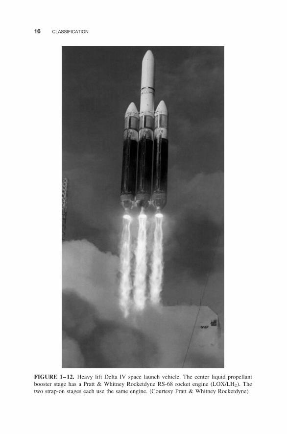
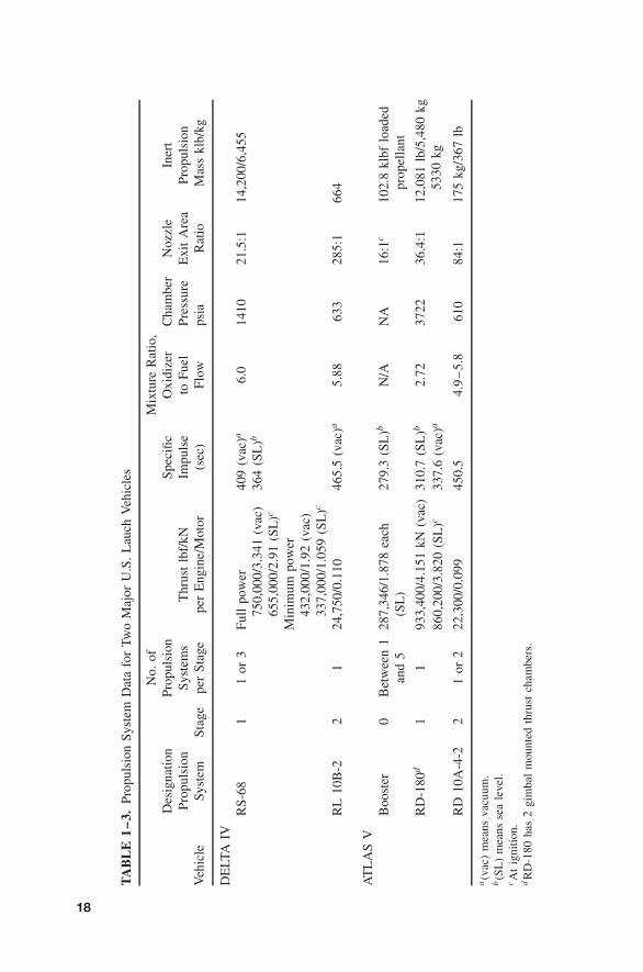
Figure 1–12 shows the Delta IV heavy-lift space launch vehicle at takeoff.Its propellants are liquid oxygen/liquid hydrogen (LOX/LH2) in all its mainengines. Its booster engine, the Pratt & Whitney Rocketdyne RS-68, is shownin Fig. 6–10 and data is in Table 11–2 and its second-stage engine, the Pratt& Whitney Rocketdyne RL 10B-2 LOX/LH2 (24,750 lb thrust) is shown in Fig.8–17 and data is in Table 8–1. The two liquid propellant strap-on booster pods(with the same booster engine) are removed for smaller payloads. Figure 1–13shows the Atlas V space launch vehicle. Its booster engine is the EnergomashRD-180, it has Aerojet solid propellant strap-on boosters, and the upper stageengine is the Pratt & Whitney Rocketdyne RL 10A-4-2 LOX/LH2 engine. TheRussian (Energomash) LOX/kerosene RD-180 engine is shown in Ref. 1–2 as itsFigure 7.10-11 and data is in its Table 7.10-2. In both of these two launch vehiclesthe payload is carried on top of the second stage and it has its own propulsionsystem of small thrusters. Table 1–3 gives data of the larger propulsion systemsof these two U.S. launch vehicles.
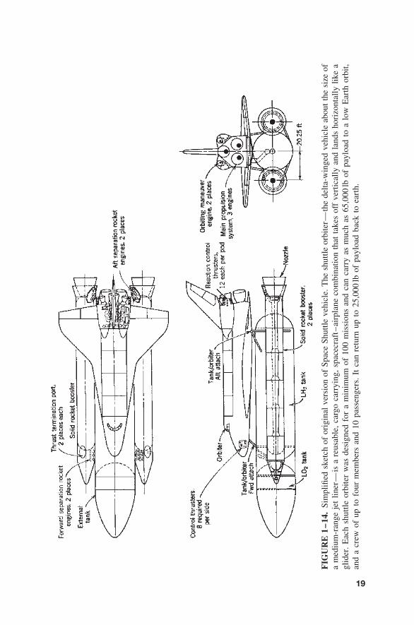
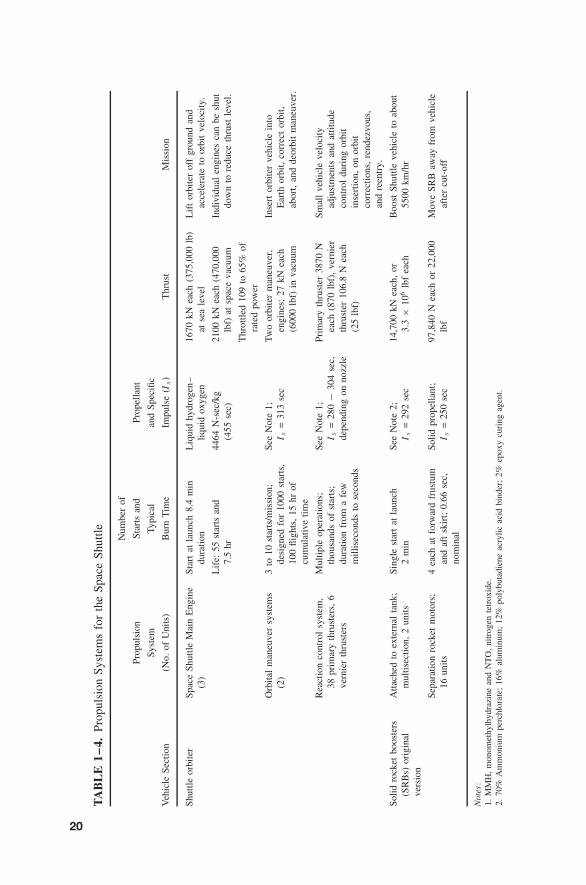
The U.S. Space Shuttle is one of the older programs and it provided thefirst reusable spacecraft that lands on a runway. Figure 1–14 shows the basicconfiguration of the Space Shuttle, which consists of two stages, the booster andthe orbiter. It shows all the 67 rocket propulsion systems of the shuttle. Theorbiter is really a reusable combination space launch vehicle, spacecraft, andglider for landing. The two solid propellant strap-on rocket motors are the largestin existence; they are equipped with parachutes for sea recovery of the burned-outmotors. The large LO2/LH2 external tank is jettisoned and expended just beforeorbit insertion (see Ref. 1–22). Details of several of these Space Shuttle rocketpropulsion systems are given in Table 1–4. The Space Shuttle accomplishes bothcivilian and military missions of placing satellites in orbit, undertaking scientificexploration, supplying a space station, and repairing, servicing, and retrievingsatellites.
16 CLASSIFICATION
FIGURE 1–12. Heavy lift Delta IV space launch vehicle. The center liquid propellantbooster stage has a Pratt & Whitney Rocketdyne RS-68 rocket engine (LOX/LH2). Thetwo strap-on stages each use the same engine. (Courtesy Pratt & Whitney Rocketdyne)

1.3. APPLICATIONS OF ROCKET PROPULSION 17
FIGURE 1–13. Atlas V space launch vehicle with three (or five) strap-on stages usingAerojet solid rocket motors and a central Energomash (Russia) RD-180 liquid propellantbooster rocket engine running on LOX/kerosene. (Courtesy Lockheed Martin Corp.)
TA
BL
E1
–3.
Prop
ulsi
onSy
stem
Dat
afo
rTw
oM
ajor
U.S
.L
auch
Veh
icle
s
No.
ofM
ixtu
reR
atio
,D
esig
natio
nPr
opul
sion
Spec
ific
Oxi
dize
rC
ham
ber
Noz
zle
Iner
tPr
opul
sion
Syst
ems
Thr
ust
lbf/
kNIm
puls
eto
Fuel
Pres
sure
Exi
tA
rea
Prop
ulsi
onV
ehic
leSy
stem
Stag
epe
rSt
age
per
Eng
ine/
Mot
or(s
ec)
Flow
psia
Rat
ioM
ass
klb/
kg
DE
LTA
IVR
S-68
11
or3
Full
pow
er75
0,00
0/3.
341
(vac
)65
5,00
0/2.
91(S
L)c
409
(vac
)a
364
(SL
)b6.
014
1021
.5:1
14,2
00/6
,455
Min
imum
pow
er43
2,00
0/1.
92(v
ac)
337,
000/
1.05
9(S
L)c
RL
10B
-22
124
,750
/0.1
1046
5.5
(vac
)a5.
8863
328
5:1
664
AT
LA
SV
Boo
ster
0B
etw
een
128
7,34
6/1.
878
each
(SL
)27
9.3
(SL
)bN
/AN
A16
:1c
102.
8kl
bflo
aded
prop
ella
ntan
d5
RD
-180
d1
193
3,40
0/4.
151
kN(v
ac)
310.
7(S
L)b
2.72
3722
36.4
:112
,081
lb/5
,480
kg53
30kg
860,
200/
3.82
0(S
L)c
337.
6(v
ac)a
RD
10A
-4-2
21
or2
22,3
00/0
.099
450.
54.
9–
5.8
610
84:1
175
kg/3
67lb
a(v
ac)
mea
nsva
cuum
.b(S
L)
mea
nsse
ale
vel.
cA
tig
nitio
n.dR
D-1
80ha
s2
gim
bal
mou
nted
thru
stch
ambe
rs.
18
FIG
UR
E1
–14
.Si
mpl
ified
sket
chof
orig
inal
vers
ion
ofSp
ace
Shut
tleve
hicl
e.T
hesh
uttle
orbi
ter—
the
delta
-win
ged
vehi
cle
abou
tth
esi
zeof
am
ediu
m-r
ange
jet
liner
—is
are
usab
le,
carg
oca
rryi
ng,
spac
ecra
ft–
airp
lane
com
bina
tion
that
take
sof
fve
rtic
ally
and
land
sho
rizo
ntal
lylik
ea
glid
er.
Eac
hsh
uttle
orbi
ter
was
desi
gned
for
am
inim
umof
100
mis
sion
san
dca
nca
rry
asm
uch
as65
,000
lbof
payl
oad
toa
low
Ear
thor
bit,
and
acr
ewof
upto
four
mem
bers
and
10pa
ssen
gers
.It
can
retu
rnup
to25
,000
lbof
payl
oad
back
toea
rth.
19
TA
BL
E1
–4.
Prop
ulsi
onSy
stem
sfo
rth
eSp
ace
Shut
tle Num
ber
of
Prop
ulsi
onSt
arts
and
Prop
ella
nt
Syst
emTy
pica
lan
dSp
ecifi
c
Veh
icle
Sect
ion
(No.
ofU
nits
)B
urn
Tim
eIm
puls
e(I
s)
Thr
ust
Mis
sion
Shu
ttle
orbi
ter
Spac
eS
hutt
leM
ain
Eng
ine
(3)
Star
tat
laun
ch8.
4m
indu
rati
onL
iqui
dhy
drog
en–
liqu
idox
ygen
1670
kNea
ch(3
75,0
00lb
)at
sea
leve
lL
ift
orbi
ter
off
grou
ndan
dac
cele
rate
toor
bit
velo
city
.
Lif
e:55
star
tsan
d7.
5hr
4464
N-s
ec/k
g(4
55se
c)21
00kN
each
(470
,000
lbf)
atsp
ace
vacu
umIn
divi
dual
engi
nes
can
besh
utdo
wn
tore
duce
thru
stle
vel.
Thr
ottl
ed10
9to
65%
ofra
ted
pow
er
Orb
ital
man
euve
rsy
stem
s(2
)3
to10
star
ts/m
issi
on;
desi
gned
for
1000
star
ts,
100
fligh
ts,
15hr
ofcu
mul
ativ
eti
me
See
Not
e1;
I s=
313
sec
Two
orbi
ter
man
euve
r,en
gine
s;27
kNea
ch(6
000
lbf)
inva
cuum
Inse
rtor
bite
rve
hicl
ein
toE
arth
orbi
t,co
rrec
tor
bit,
abor
t,an
dde
orbi
tm
aneu
ver.
Rea
ctio
nco
ntro
lsy
stem
,38
prim
ary
thru
ster
s,6
vern
ier
thru
ster
s
Mul
tipl
eop
erat
ions
;th
ousa
nds
ofst
arts
;du
rati
onfr
oma
few
mill
isec
onds
tose
cond
s
See
Not
e1;
I s=
280
−30
4se
c,de
pend
ing
onno
zzle
Prim
ary
thru
ster
3870
Nea
ch(8
70lb
f),
vern
ier
thru
ster
106.
8N
each
(25
lbf)
Sm
all
vehi
cle
velo
city
adju
stm
ents
and
atti
tude
cont
rol
duri
ngor
bit
inse
rtio
n,on
orbi
tco
rrec
tion
s,re
ndez
vous
,an
dre
entr
y.
Soli
dro
cket
boos
ters
(SR
Bs)
orig
inal
vers
ion
Att
ache
dto
exte
rnal
tank
;m
ulti
sect
ion,
2un
its
Sing
lest
art
atla
unch
2m
inSe
eN
ote
2;I s
=29
2se
c14
,700
kNea
ch,
or3.
3×
106
lbf
each
Boo
stSh
uttle
vehi
cle
toab
out
5500
km/h
r
Sepa
rati
onro
cket
mot
ors;
16un
its
4ea
chat
forw
ard
frus
tum
and
aft
skir
t;0.
66se
c,no
min
al
Soli
dpr
opel
lant
;I s
=25
0se
c97
,840
Nea
chor
22,0
00lb
fM
ove
SRB
away
from
vehi
cle
afte
rcu
t-of
f
Not
es:
1.M
MH
,m
onom
ethy
lhyd
razi
nean
dN
TO
,ni
trog
ente
trox
ide.
2.70
%A
mm
oniu
mpe
rchl
orat
e;16
%al
umin
um;
12%
poly
buta
dien
eac
rylic
acid
bind
er;
2%ep
oxy
curi
ngag
ent.
20

1.3. APPLICATIONS OF ROCKET PROPULSION 21
Table 1–4 gives propulsion system data on the Space Shuttle, which is reallya combination of launch vehicle, spacecraft, and a glider. It can be seen thatthe thrust levels are highest for booster or first stages and are relatively high forupper stages (thousands of pounds). Only for the attitude control system of thevehicle (also called reaction control in Table 1–4) are the thrust levels low (froma fraction of a pound for small spacecraft to as high as about 1000 pounds thrustin the Space Shuttle vehicle). Frequent propulsion starts and stops are usuallyrequired in these applications.
At the time of this writing (early 2008) for this new 8th edition NationalAeronautics and Space Administration (NASA) had awarded the initial contractsfor a new large manned space flight vehicle identified as Ares I. It is intendedto replace the aging Space Shuttle after about 2012. It is planned to use a largesingle 5-segment solid rocket motor as booster propulsion (being developed byATK Launch Systems) and the second stage will use a J-2X liquid propellantrocket engine with LOX/LH2 propellants (being developed by Pratt & WhitneyRocketdyne).
A new set of manned space flight vehicles are currently being developed byseveral entrepreneurial US and foreign companies, many with their own privatecapital. They are aimed at the future commercial market of sending tourists(for a hefty price) into space and returning them safely back to earth. All arebased on reusable spacecraft, some with reusable launch vehicles, some withvertical and some with horizontal takeoff or landing. A couple of suborbital flightshave already been accomplished with professional pilots using a winged vehicle.Liquid propellant rocket engines seem to be preferred and many are planned tobe reusable. It is too early for determining which of these organizations will besuccessful in commercializing manned space flight.
The missions and payloads for space launch vehicles are many, such asmilitary (reconnaissance satellites, command and control satellites), nonmili-tary government [weather observation satellites, global positioning system (GPS)satellites], space exploration (space environment, planetary missions), or com-mercial (communication satellites).
A single stage-to-orbit vehicle, attractive because it avoids the costs and com-plexities of staging, has been expected to have improved reliability (simplerstructures, fewer components). However, its payload is usually too small. A lowearth orbit (say 100 miles altitude) can only be achieved with such a vehicleif the propellant performance is very high and the structure is efficient and lowin mass. Liquid propellants such as liquid hydrogen with liquid oxygen wereusually chosen. To date a large rocket-propelled single stage-to-orbit vehicle hasnot flown.
Spacecraft
Depending on their missions, spacecraft can be categorized as earth satellites,lunar, interplanetary, and trans-solar types, and as manned and unmannedspacecraft. Reference 1–23 lists over 20,000 satellites and categorizes them assatellites for communications, weather, navigation, scientific exploration, deep
22 CLASSIFICATION
space probes, observation (including radar surveillance), reconnaissance andother applications. Rocket propulsion is used for both primary propulsion (i.e.,acceleration along the flight path, such as for orbit insertion or orbit changemaneuvers) and secondary propulsion functions in these vehicles. Some of thesecondary propulsion functions are attitude control, spin control, momentumwheel and gyro unloading, stage separation, and the settling of liquids in tanks.A spacecraft usually has a series of different rocket propulsion systems, someoften very small. For spacecraft attitude control about three perpendicular axes,each in two rotational directions, the system must allow the application of puretorque for six modes of angular freedom, thus requiring a minimum of 12thrusters. Some missions require as few as 4 to 6 thrusters, whereas the morecomplex manned spacecraft have 40 to 80 thrusters in all of its stages. Oftenthe small attitude control rockets must give pulses or short bursts of thrust,necessitating thousands of restarts. See Section 6.7 and Ref. 1–24.
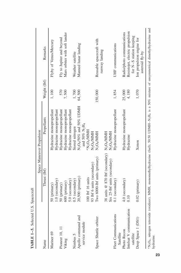
Table 1–5 presents a variety of spacecraft along with their weights, missions,and propulsion. Although only U.S. launch vehicles are listed in this table, thereare also launch vehicles developed by France, the European Space Agency, Rus-sia, Japan, China, India, and Israel that have successfully launched payloads intosatellite orbits. They use rocket propulsion systems that were developed in theirown countries.
The majority of spacecraft have used liquid propellant engines, a few with solidpropellant boosters. Many spacecraft have operated successfully with electricalpropulsion for attitude control. Electrical propulsion systems will probably alsobe used for some primary and secondary spacecraft propulsion missions on long-duration space flights, as described in Chapter 17.
Micropropulsion is a relatively new designation. It has been defined as anyrocket propulsion system that is applicable to small spacecraft with a mass ofless than 100 kg, or 220 lb. See Ref. 1–25. It encompasses a variety of differentpropulsion concepts, such as certain very low thrust liquid mono- and bipropellantrocket engines, small gaseous propellant rocket engines, several types of electricalpropulsion systems, and emerging advanced versions of these. Many are basedon fabrication of very small components (valves, thrusters, switches, insulators,or sensors) by micromachining and electromechanical processes.
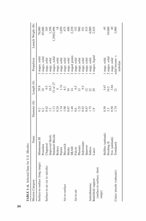
Missiles and Other Applications
Military missiles can be classified as shown in Table 1–6. Rocket propulsion fornew U.S. missiles uses now almost exclusively solid propellant rocket motors.They can be strategic missiles , such as long-range ballistic missiles (800 to9000 km range), which are aimed at military targets within an enemy country, ortactical missiles , which are intended to support or defend military ground forces,aircraft, or navy ships.
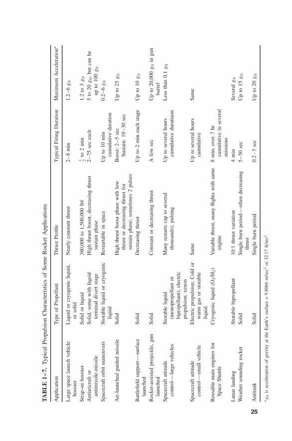
Tables 1–6 and 1–7 show some parameters of rocket propulsion devicesfor different applications. The selection of the best rocket propulsion systemtype and design for any given application is a complex process involving manyfactors, including system performance, reliability, propulsion system size, andcompatibility, as described in Chapter 19.
TA
BL
E1
–5.
Sele
cted
U.S
.Sp
acec
raft
Spac
eM
aneu
ver
Prop
ulsi
on
Nam
eT
hrus
t(l
bf)
Prop
ella
nts
Wei
ght
(lbf
)R
emar
ks
Mar
iner
6950
(pri
mar
y)H
ydra
zine
mon
opro
pella
nt1,
100
Flyb
yof
Ven
us/M
ercu
ry1.
0(s
econ
dary
)H
ydra
zine
mon
opro
pella
ntPi
onee
r10
,11
50(p
rim
ary)
Hyd
razi
nem
onop
rope
llant
570
Fly
toJu
pite
ran
dbe
yond
Vik
ing
600
(pri
mar
y)H
ydra
zine
mon
opro
pella
nt7,
500
Mar
sor
bite
rw
ithso
ftla
nder
5.0
(sec
onda
ry)
Hyd
razi
nem
onop
rope
llant
Nim
bus
50.
5(s
econ
dary
)St
ored
nitr
ogen
1,70
0W
eath
ersa
telli
teA
pollo
com
man
dan
dse
rvic
em
odul
e20
,500
(pri
mar
y)N
2O
4/5
0%an
d50
%U
DM
Han
d50
%N
2H
4
64,5
00M
anne
dlu
nar
land
ing
100
lbf
16un
its
aN
2O
4/M
MH
93lb
f6
units
(sec
onda
ry)
N2O
4/M
MH
Spac
eSh
uttle
orbi
ter
Two
6000
-lbf
units
(pri
mar
y)N
2O
4/M
MH
150,
000
Reu
sabl
esp
acec
raft
with
runw
ayla
ndin
g38
units
@87
0lb
f(s
econ
dary
)N
2O
4/M
MH
Six
25-l
bfun
its(s
econ
dary
)N
2O
4/M
MH
Flee
tC
omm
unic
atio
nsSa
telli
te0.
1(s
econ
dary
)H
ydra
zine
mon
opro
pella
nt1,
854
UH
Fco
mm
unic
atio
ns
Phot
oR
econ
4.0
(sec
onda
ry)
Hyd
razi
nem
onop
rope
llant
25,0
00R
adio
/pho
toco
mm
unic
atio
nsIn
tels
atV
com
mun
icat
ion
sate
llit
e0.
10H
ydra
zine
4,18
0R
esis
toje
t,el
ectr
icpr
opul
sion
for
N–
Sst
atio
nke
epin
gD
eep
Spac
e1
(DS1
)0.
02(p
rim
ary)
Xen
on1,
070
Ion
prop
ulsi
onen
gine
for
aste
roid
fly-b
y
aN
2O
4,
nitr
ogen
tetr
oxid
e(o
xidi
zer)
;M
MH
,m
onom
ethy
lhyd
razi
ne(f
uel)
;50
:50
UD
MH
–N
2H
4is
a50
%m
ixtu
reof
unsy
mm
etri
cal
dim
ethy
lhyd
razi
nean
dhy
draz
ine.
23
TA
BL
E1
–6.
Sele
cted
Dat
afo
rU
.S.
Mis
sile
s
Mis
sion
Cat
egor
yN
ame
Dia
met
er(f
t)L
engt
h(f
t)Pr
opul
sion
Lau
nch
Wei
ght
(lb)
Surf
ace-
to-s
urfa
ce(l
ong
rang
e)M
inut
eman
III
6.2
59.8
3st
ages
,so
lid78
,000
Pose
idon
6.2
342
stag
es,
solid
65,0
00Su
rfac
e-to
-air
(or
tom
issi
le)
Cha
parr
al0.
429.
51
stag
e,so
lid18
5Im
prov
edH
awk
1.2
16.5
1st
age,
solid
1,39
8St
anda
rdM
issi
le1.
1315
or27
2st
ages
,so
lid
1,35
0/2,
996
Red
eye
0.24
41
stag
e,so
lid
18Pa
trio
t1.
341.
741
stag
e,so
lid1,
850
Air
-to-
surf
ace
Mav
eric
k1.
008.
21
stag
e,so
lid47
5Sh
rike
0.67
101
stag
e,so
lid
400
SRA
M1.
4614
2st
aged
grai
ns2,
230
Air
-to-
air
Falc
on0.
66.
51
stag
e,so
lid15
2Ph
oeni
x1.
2513
1st
age,
soli
d98
0Si
dew
inde
r0.
429.
51
stag
e,so
lid19
1Sp
arro
w0.
6712
1st
age,
soli
d51
5A
ntis
ubm
arin
eSu
broc
1.75
221
stag
e,so
lid4,
000
Bat
tlefie
ldsu
ppor
t(s
urfa
ce-t
o-su
rfac
e,sh
ort
rang
e)
Lan
ce1.
820
2st
ages
,liq
uid
2,42
4
Hel
lfire
(ant
itank
)0.
585.
671
stag
e,so
lid95
Pers
hing
II3.
334
.52
stag
es,
solid
10,0
00To
w(a
ntit
ank)
0.58
3.84
1st
age,
solid
40C
ruis
em
issi
le(s
ubso
nic)
Tom
ahaw
k1.
7421
soli
dbo
oste
r+
turb
ofan
3,90
0
24
TA
BL
E1
–7.
Typi
cal
Prop
ulsi
onC
hara
cter
istic
sof
Som
eR
ocke
tA
pplic
atio
ns
App
licat
ion
Type
ofPr
opel
lant
Thr
ust
Profi
leTy
pica
lFi
ring
Dur
atio
nM
axim
umA
ccel
erat
iona
Lar
gesp
ace
laun
chve
hicl
ebo
oste
rL
iqui
dor
cryo
geni
cliq
uid,
orso
lidN
earl
yco
nsta
ntth
rust
2–
8m
in1.
2–
6g
0
Stra
p-on
boos
ter
Solid
orliq
uid
380,
000
to1,
500,
000
lbf
1 2to
2m
in1.
2to
3g
0
Ant
iari
craf
tor
antim
issi
le-m
issi
leSo
lid,
som
ew
ithliq
uid
term
inal
dive
rtst
age
Hig
hth
rust
boos
t,de
crea
sing
thru
stsu
stai
nph
ase
2–
75se
cea
ch5
to20
g0,
but
can
beup
to10
0g
0
Spac
ecra
ftor
bit
man
euve
rsSt
orab
leliq
uid
orcr
yoge
nic
liqui
dR
esta
rtab
lein
spac
eU
pto
10m
incu
mul
ativ
edu
ratio
n0.
2–
6g
0
Air
-lau
nche
dgu
ided
mis
sile
Solid
Hig
hth
rust
boos
tph
ase
with
low
thru
stor
decr
easi
ngth
rust
for
sust
ain
phas
e;so
met
imes
2pu
lses
Boo
st:
2–
5se
cSu
stai
n:10
–30
sec
Up
to25
g0
Bat
tlefie
ldsu
ppor
t—su
rfac
ela
unch
edSo
lidD
ecre
asin
gth
rust
Up
to2
min
each
stag
eU
pto
10g
0
Roc
ket-
assi
sted
proj
ectil
e,gu
nla
unch
edSo
lidC
onst
ant
orde
crea
sing
thru
stA
few
sec
Up
to20
,000
g0
ingu
nba
rrel
Spac
ecra
ftat
titud
eco
ntro
l—la
rge
vehi
cles
Stor
able
liqui
d(m
onop
rope
llant
orbi
prop
ella
nt);
elec
tric
prop
ulsi
on;
xeno
n
Man
yre
star
ts(u
pto
seve
ral
thou
sand
s);
puls
ing
Up
tose
vera
lho
urs
cum
ulat
ive
dura
tiaon
Les
sth
an0.
1g
0
Spac
ecra
ftat
titud
eco
ntro
l—sm
all
vehi
cle
Ele
ctri
cpr
opul
sion
;C
old
orw
arm
gas
orst
orab
leliq
uid.
Sam
eU
pto
seve
ral
hour
scu
mul
ativ
eSa
me
Reu
sabl
em
ain
engi
nes
for
Spac
eSh
uttle
Cry
ogen
icliq
uid
(O2/H
2)
Var
iabl
eth
rust
,m
any
fligh
tsw
ithsa
me
engi
ne8
min
,ov
er7
hrcu
mul
ativ
ein
seve
ral
mis
sion
sL
unar
land
ing
Stor
able
bipr
opel
lant
10:1
thru
stva
riat
ion
4m
inSe
vera
lg
0
Wea
ther
soun
ding
rock
etSo
lidSi
ngle
burn
peri
od—
ofte
nde
crea
sing
thru
st5
–50
sec
Up
to15
g0
Ant
itank
Solid
Sing
lebu
rnpe
riod
0.2
–3
sec
Up
to20
g0
ag
0is
acce
lera
tion
ofgr
avity
atth
eE
arth
’ssu
rfac
e=
9.80
66m
/sec
2or
32.1
7ft
/sec
2.
25
26 CLASSIFICATION
The term surface launch can mean a launch from the ground, the ocean surface(from a ship), or from underneath the sea (submarine launch). Some tacticalmissiles, such as the air-to-surface short-range attack missile (SRAM), have atwo-pulse solid propellant motor, where two separate, insulated grains are in thesame motor case; the time interval before starting the second pulse can be timed tocontrol the flight path or speed profile. Most countries now have tactical missilesin their military inventories, and many of these countries have a capability toproduce their own rocket propulsion systems that are used to propel them.
Solid propellant rocket motors are being used today in most tactical missiles,such as in surface-to-air, air-to-air, air-to-surface, and surface-to-surface appli-cations, for the ejection of pilot aircraft seats or crew capsules, target drones,signal rockets, weather sounding rockets, antitank rockets, or for the separationsof stages in a multistage flight vehicle.
Applications, which were popular 30 to 60 years ago, but are no longer active,include liquid propellant rocket engines for propelling military fighter aircraft,assisted takeoff rocket engines and rocket motors, and superperformance rocketengines for augmenting the thrust of an aircraft jet engine.
REFERENCES
1–1. E. C. Goddard and G. E. Pendray (Eds), The Papers of Robert H. Goddard ,three volumes, McGraw-Hill Book Company, 1970, 1707 pages. It includesthe pioneering treatise “A Method of Reaching Extreme Altitudes” originallypublished as Smithsonian Miscellaneous Collections, Vol. 71, No. 2, 1919.
1–2. G. P. Sutton, History of Liquid Propellant Rocket Engines , published by AIAA,2006, 911 pages.
1–3. B. N. Yur’yev (Ed), Collected Works of K. E. Tsiolkowski , Vols. 1–3, USSRAcademy of Sciences, 1951; also NASA Technical Translation F-236, April 1965.
1–4. H. Oberth, Die Rakete zu den Planetenraumen (By Rocket to Planetary Space),R. Oldenburg, Munich, 1923 (in German), a classical text.
1–5. E. Sanger, Raketenflugtechnik (Rocket Flight Technology), R. Oldenburg, Hunich,1923 (in German).
1–6. W. von Braun and F. Ordway, History of Rocketry and Space Travel , 3rd ed.,Thomas Y. Crowell, New York, 1974.
1–7. L. H. Caveny, R. L. Geisler, R. A. Ellis, and T. L. Moore, “Solid EnablingTechnologies and Milestones in the USA,” Journal of Propulsion and Power , Vol.19, No. 6, Nov.–Dec. 2003, AIAA, pp. 1038–1066.
1–8. A. M. Lipanov, “Historical Survey of Solid Propellant Rocket Development inRussia,” Journal of Propulsion and Power , Vol. 19, No. 6. Nov.–Dec. 2003, pp.1063–1088.
1–9. AGARD Lecture Series 150, Design Methods in Solid Rocket Motors ,AGARD/NATO, Paris, April 1988.
1–10. A. Davenas, Solid Rocket Propulsion Technology , Pergamon Press, London (orig-inally published in French), 1988.
REFERENCES 27
1–11. S. V. Gunn and C. M. Ehresman, “The Space Propulsion Technology BaseEstablished Four Decades Ago for the Thermal Nuclear Rocket Is Ready forCurrent Application,” AIAA paper 2003–4590, July 2003.
1–12. R. W. Bussard and R. D. DeLauer, Nuclear Rocket Propulsion , McGraw-HillBook Company, New York, 1958.
1–13. D. Buden, “Nuclear Rocket Safety,” Acta Astronautica , Vol. 18, 30 Years ofProgress in Space, 1988, pp. 217–224.
1–14. R. C. Finke (Ed), Electric Propulsion and Its Application to Space Missions ,Vol. 79, Progress in Aeronautics and Astronautics Series, AIAA 1981.
1–15. R. G. Jahn, Physics of Electrical Propulsion , McGraw-Hill Book Company, NewYork, 1968, 339 pages.
1–16. T. Svitek et al., “Solar Sails as Orbit Transfer Vehicle—Solar Sail Concept Study,”Phase II Report, AIAA paper 83–1347, 1983.
1–17. V. P. Ageev et al., “Some Characteristics of the Laser Multi-pulse Explosive TypeJet Thruster,” Acta Astronautica , Vol. 8, No. 5–6, 1981, pp. 625–641.
1–18. R. A. Hyde, “A Laser Fusion Rocket for Interplanetary Propulsion,” PreprintUCRL 88857, Lawrence Livermore National Laboratory, Livermore, California,Sept. 1983.
1–19. NASA International Space Station (A resource on the ISS by NASA; includesoperational use, wide range of background material, archives, image gallery andplanned missions) www.nase.gov/station-34k.
1–20. T. D. Thompson (Ed), TRW Space Log , Vols. 31 to 34, TRW Space and ElectronicsGroup (today part of Northrop Grumman Corp.), Redondo Beach, CA, 1996 and1997–1998.
1–21. S. J. Isakowitz, J. B. Hopkins, and J. P. Hopkins, International Reference Guideto Space Launch Systems , 4th ed., AIAA, 2004, 596 pages.
1–22. National Aeronautics and Space Administration (NASA), National Space Trans-portation System Reference, Vol. 1, Systems and Facilities , U.S. GovernmentPrinting Office, Washington, DC, June 1988; a description of the Space Shuttle.
1–23. A. R. Curtis (Ed), Space Satellite Handbook , 3rd ed, Gulf Publishing Company,Houston, TX, 1994, 346 pages.
1–24. G. P. Sutton, History of Small Liquid Propellant Thrusters , presented at the 52ndJANNAF Propulsion Meeting, May 2004, Las Vegas, NE, published by the Chem-ical Propulsion Information Analysis Center, Columbia, Maryland, June 2004.
1–25. M. M. Micci and A. D. Ketsdever, Micropropulsion for Small Spacecraft , Progressin Aeronautics and Astronautics Series, Vol. 187, AIAA, 2000, 477 pages.

![INDEX 1205 [catalogimages.wiley.com]](https://static.fdocuments.in/doc/165x107/6285875d2522e359a13adc54/index-1205-.jpg)


