List Of Contentsbryantrv.com/docs2/docs/sanyosrae07xx.pdfList Of Contents -, ... ous trickle of weak...
44
List Of Contents -, Para Page Absorption Cooling Unit Diagram ........................................................... 2 .......................................................... 1 The Absorption Type Cooling Unit 3 ............................................................... 2 The Domestic Refrigerator 4 .............................................................. 3 Three Points To Remember 5 .................................................................... System Operation 7 Installation Instructions For LP Gas Refrigerator .................................................. 8 ........................................................ Installation Of Refrigerator In Trailers 9 GasLine ........................................................................ 13 GasBurner ....................................................................... 13 Burner Orifice & Mixture Tube ........................................................... 14 Burner Orifice Clogged ................................................................ 15 ................................................... Check Of The Ignition Plug & ~hermocou~le 16 FlueSystem ...................................................................... 17 Pressure Measuring Devices ............................................................. 18 Power. Current. Resistance Chart .......................................................... 20 Heating Elements For Different Refrigerators ................................................... 21 Leveling ........................................................................ 21 Temperature Control ................................................................. 21 Thermalsensor .................................................................... 22 Storing Food In The Refrigerator .......................................................... 22 Cleaning ........................................................................ 22 IceCubes ........................................................................ 22 TravelLock ...................................................................... 22 To Shut Off The Cabinet ............................................................... 23 DoorSeal ....................................................................... 23 Flue Obstructions ................................................................... 23 Odors Inside The Refrigerator ............................................................ 23 OdorsFromFumes .................................................................. 24 6-75 . Operation Analysis For Cooling Unit ........................................................ 24 .$ . . . .tl f Unit Filling Valve ................................................................... 25 Things To Do Before Sending Back Defective Units To Distributor ...................................... 25 31 Packing Of Defective Units .............................................................. 25 32 Wiring Diagram ..................................................................... 26 33 Trouble Shooting .................................................................... 28 ........................................... 34 Changing Printed Wiring Board Ass'y (Switch) And Buzzer 34 ................................................... 35 Changing Printed Wiring Board Ass'y (Main) 35 ..................................................................... 36 ChangingFuse 35 37 Changing Printed Wiring Board Ass'y (Thermocouple) .............................................. 36 38 Changing Transformer ................................................................ 36 39 Changing Relay (Only For SRAE 0732. 1232) .................................................. 36 40 Changing Ignition Plug ................................................................ 36 ............................................................... 41 Changing Thermocouple 37 .............................................................. Changing Thermal Sensor 37 .................................................................... Changing Heater 38 ............................................................... Changing Solenoid Valve 38 .................................................................. Changing Gas Filter 38 ................................................................ Changing Manual Valve 39 .................................................... Changing Cooling Unit (SRAE 1222, 1232) 39 .................................................... Changing Cooling Unit (SRAE 0722.0732) 40 ................................................................ Changing Door Gasket 41 .................................................................. Changing Door Liner 41 ..................................................... Instruction For Mounting The Door Panel 42 ........................................................... Interchanging Of Door Opening 43 ........................................................... 53 Changing Cabinet Frame Ass'y 44 54 PartsList ........................................................................ 46
Transcript of List Of Contentsbryantrv.com/docs2/docs/sanyosrae07xx.pdfList Of Contents -, ... ous trickle of weak...
List Of Contents -,
Para Page Absorption Cooling Unit Diagram . . . . . . . . . . . . . . . . . . . . . . . . . . . . . . . . . . . . . . . . . . . . . . . . . . . . . . . . . . . 2
. . . . . . . . . . . . . . . . . . . . . . . . . . . . . . . . . . . . . . . . . . . . . . . . . . . . . . . . . . 1 The Absorption Type Cooling Unit 3 . . . . . . . . . . . . . . . . . . . . . . . . . . . . . . . . . . . . . . . . . . . . . . . . . . . . . . . . . . . . . . . 2 The Domestic Refrigerator 4
. . . . . . . . . . . . . . . . . . . . . . . . . . . . . . . . . . . . . . . . . . . . . . . . . . . . . . . . . . . . . . 3 Three Points To Remember 5 . . . . . . . . . . . . . . . . . . . . . . . . . . . . . . . . . . . . . . . . . . . . . . . . . . . . . . . . . . . . . . . . . . . . System Operation 7
Installation Instructions For LP Gas Refrigerator . . . . . . . . . . . . . . . . . . . . . . . . . . . . . . . . . . . . . . . . . . . . . . . . . . 8 . . . . . . . . . . . . . . . . . . . . . . . . . . . . . . . . . . . . . . . . . . . . . . . . . . . . . . . . Installation Of Refrigerator In Trailers 9
GasLine . . . . . . . . . . . . . . . . . . . . . . . . . . . . . . . . . . . . . . . . . . . . . . . . . . . . . . . . . . . . . . . . . . . . . . . . 13 GasBurner . . . . . . . . . . . . . . . . . . . . . . . . . . . . . . . . . . . . . . . . . . . . . . . . . . . . . . . . . . . . . . . . . . . . . . . 13 Burner Orifice & Mixture Tube . . . . . . . . . . . . . . . . . . . . . . . . . . . . . . . . . . . . . . . . . . . . . . . . . . . . . . . . . . . 14 Burner Orifice Clogged . . . . . . . . . . . . . . . . . . . . . . . . . . . . . . . . . . . . . . . . . . . . . . . . . . . . . . . . . . . . . . . . 15
. . . . . . . . . . . . . . . . . . . . . . . . . . . . . . . . . . . . . . . . . . . . . . . . . . . Check Of The Ignition Plug & ~ h e r m o c o u ~ l e 16 FlueSystem . . . . . . . . . . . . . . . . . . . . . . . . . . . . . . . . . . . . . . . . . . . . . . . . . . . . . . . . . . . . . . . . . . . . . . 17 Pressure Measuring Devices . . . . . . . . . . . . . . . . . . . . . . . . . . . . . . . . . . . . . . . . . . . . . . . . . . . . . . . . . . . . . 18 Power. Current. Resistance Chart . . . . . . . . . . . . . . . . . . . . . . . . . . . . . . . . . . . . . . . . . . . . . . . . . . . . . . . . . . 20 Heating Elements For Different Refrigerators . . . . . . . . . . . . . . . . . . . . . . . . . . . . . . . . . . . . . . . . . . . . . . . . . . . 21 Leveling . . . . . . . . . . . . . . . . . . . . . . . . . . . . . . . . . . . . . . . . . . . . . . . . . . . . . . . . . . . . . . . . . . . . . . . . 21 Temperature Control . . . . . . . . . . . . . . . . . . . . . . . . . . . . . . . . . . . . . . . . . . . . . . . . . . . . . . . . . . . . . . . . . 21 Thermalsensor . . . . . . . . . . . . . . . . . . . . . . . . . . . . . . . . . . . . . . . . . . . . . . . . . . . . . . . . . . . . . . . . . . . . 22 Storing Food In The Refrigerator . . . . . . . . . . . . . . . . . . . . . . . . . . . . . . . . . . . . . . . . . . . . . . . . . . . . . . . . . . 22 Cleaning . . . . . . . . . . . . . . . . . . . . . . . . . . . . . . . . . . . . . . . . . . . . . . . . . . . . . . . . . . . . . . . . . . . . . . . . 22 IceCubes . . . . . . . . . . . . . . . . . . . . . . . . . . . . . . . . . . . . . . . . . . . . . . . . . . . . . . . . . . . . . . . . . . . . . . . . 22 TravelLock . . . . . . . . . . . . . . . . . . . . . . . . . . . . . . . . . . . . . . . . . . . . . . . . . . . . . . . . . . . . . . . . . . . . . . 22 To Shut Off The Cabinet . . . . . . . . . . . . . . . . . . . . . . . . . . . . . . . . . . . . . . . . . . . . . . . . . . . . . . . . . . . . . . . 23 DoorSeal . . . . . . . . . . . . . . . . . . . . . . . . . . . . . . . . . . . . . . . . . . . . . . . . . . . . . . . . . . . . . . . . . . . . . . . 23 Flue Obstructions . . . . . . . . . . . . . . . . . . . . . . . . . . . . . . . . . . . . . . . . . . . . . . . . . . . . . . . . . . . . . . . . . . . 23 Odors Inside The Refrigerator . . . . . . . . . . . . . . . . . . . . . . . . . . . . . . . . . . . . . . . . . . . . . . . . . . . . . . . . . . . . 23 OdorsFromFumes . . . . . . . . . . . . . . . . . . . . . . . . . . . . . . . . . . . . . . . . . . . . . . . . . . . . . . . . . . . . . . . . . . 24 6-75 .
Operation Analysis For Cooling Unit . . . . . . . . . . . . . . . . . . . . . . . . . . . . . . . . . . . . . . . . . . . . . . . . . . . . . . . . 24 .$ . . . .tl f Unit Filling Valve . . . . . . . . . . . . . . . . . . . . . . . . . . . . . . . . . . . . . . . . . . . . . . . . . . . . . . . . . . . . . . . . . . . 25 Things To Do Before Sending Back Defective Units To Distributor . . . . . . . . . . . . . . . . . . . . . . . . . . . . . . . . . . . . . . 25
31 Packing Of Defective Units . . . . . . . . . . . . . . . . . . . . . . . . . . . . . . . . . . . . . . . . . . . . . . . . . . . . . . . . . . . . . . 25 32 Wiring Diagram . . . . . . . . . . . . . . . . . . . . . . . . . . . . . . . . . . . . . . . . . . . . . . . . . . . . . . . . . . . . . . . . . . . . . 26 33 Trouble Shooting . . . . . . . . . . . . . . . . . . . . . . . . . . . . . . . . . . . . . . . . . . . . . . . . . . . . . . . . . . . . . . . . . . . . 28
. . . . . . . . . . . . . . . . . . . . . . . . . . . . . . . . . . . . . . . . . . . 34 Changing Printed Wiring Board Ass'y (Switch) And Buzzer 34 . . . . . . . . . . . . . . . . . . . . . . . . . . . . . . . . . . . . . . . . . . . . . . . . . . . 35 Changing Printed Wiring Board Ass'y (Main) 35
. . . . . . . . . . . . . . . . . . . . . . . . . . . . . . . . . . . . . . . . . . . . . . . . . . . . . . . . . . . . . . . . . . . . . 36 ChangingFuse 35 37 Changing Printed Wiring Board Ass'y (Thermocouple) . . . . . . . . . . . . . . . . . . . . . . . . . . . . . . . . . . . . . . . . . . . . . . 36 38 Changing Transformer . . . . . . . . . . . . . . . . . . . . . . . . . . . . . . . . . . . . . . . . . . . . . . . . . . . . . . . . . . . . . . . . 36 39 Changing Relay (Only For SRAE 0732. 1232) . . . . . . . . . . . . . . . . . . . . . . . . . . . . . . . . . . . . . . . . . . . . . . . . . . 36 40 Changing Ignition Plug . . . . . . . . . . . . . . . . . . . . . . . . . . . . . . . . . . . . . . . . . . . . . . . . . . . . . . . . . . . . . . . . 36
. . . . . . . . . . . . . . . . . . . . . . . . . . . . . . . . . . . . . . . . . . . . . . . . . . . . . . . . . . . . . . . 41 Changing Thermocouple 37 . . . . . . . . . . . . . . . . . . . . . . . . . . . . . . . . . . . . . . . . . . . . . . . . . . . . . . . . . . . . . . Changing Thermal Sensor 37
. . . . . . . . . . . . . . . . . . . . . . . . . . . . . . . . . . . . . . . . . . . . . . . . . . . . . . . . . . . . . . . . . . . . Changing Heater 38 . . . . . . . . . . . . . . . . . . . . . . . . . . . . . . . . . . . . . . . . . . . . . . . . . . . . . . . . . . . . . . . Changing Solenoid Valve 38
. . . . . . . . . . . . . . . . . . . . . . . . . . . . . . . . . . . . . . . . . . . . . . . . . . . . . . . . . . . . . . . . . . Changing Gas Filter 38 . . . . . . . . . . . . . . . . . . . . . . . . . . . . . . . . . . . . . . . . . . . . . . . . . . . . . . . . . . . . . . . . Changing Manual Valve 39
. . . . . . . . . . . . . . . . . . . . . . . . . . . . . . . . . . . . . . . . . . . . . . . . . . . . Changing Cooling Unit (SRAE 1222, 1232) 39
. . . . . . . . . . . . . . . . . . . . . . . . . . . . . . . . . . . . . . . . . . . . . . . . . . . . Changing Cooling Unit (SRAE 0722.0732) 40 . . . . . . . . . . . . . . . . . . . . . . . . . . . . . . . . . . . . . . . . . . . . . . . . . . . . . . . . . . . . . . . . Changing Door Gasket 41
. . . . . . . . . . . . . . . . . . . . . . . . . . . . . . . . . . . . . . . . . . . . . . . . . . . . . . . . . . . . . . . . . . Changing Door Liner 41 . . . . . . . . . . . . . . . . . . . . . . . . . . . . . . . . . . . . . . . . . . . . . . . . . . . . . Instruction For Mounting The Door Panel 42
. . . . . . . . . . . . . . . . . . . . . . . . . . . . . . . . . . . . . . . . . . . . . . . . . . . . . . . . . . . Interchanging Of Door Opening 43
. . . . . . . . . . . . . . . . . . . . . . . . . . . . . . . . . . . . . . . . . . . . . . . . . . . . . . . . . . . 53 Changing Cabinet Frame Ass'y 44 54 PartsList . . . . . . . . . . . . . . . . . . . . . . . . . . . . . . . . . . . . . . . . . . . . . . . . . . . . . . . . . . . . . . . . . . . . . . . . 46
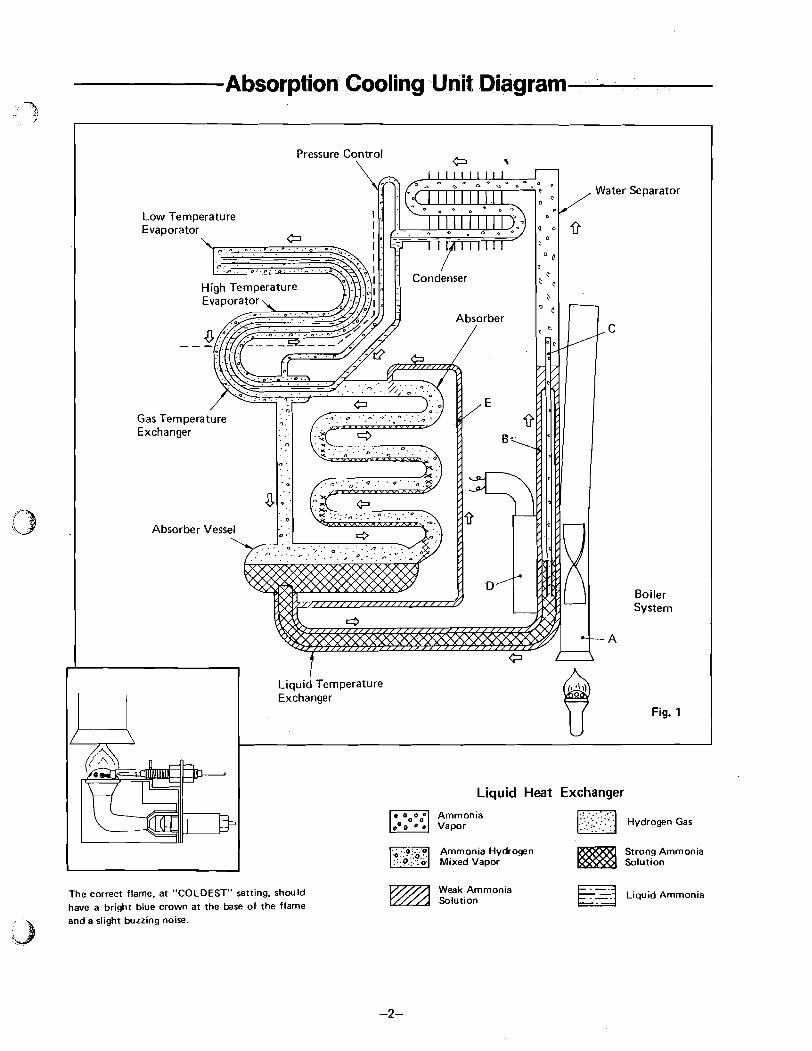
Absorption Cooling Unit Diagram
Low Temperature
Gas Temperature Exchanger
Absorber Vess
Liquid Heat Exchanger
Strong Ammonia
The correct flame, at "COLDEST" setting. should have a bright blue crown at the base of the flame and a slight buzzing noise.
Weak Ammonia Solution Liquid Ammonia

1. The Absorption Type Cooling Unit 9, .. + < /
The continuous absorption type of cooling unit IS oper- The strong ammonia solution produced in the absorber ated by the application of a limited amount of heat, gas, flows down to the absorber vessel and thence to the electricity or kerosene. No moving parts are employed. boiler system, thus completing the full cycle of opera-
The unit, (see Fig. 1 ), consists of four main parts - the boiler system, condenser, evaporator and absorber. All the parts are connected by tubes, the whole con- struction being of steel welded together.
The unit (in Fig. 1) can either be run on electricity or gas. On the picture the unit operates on LP gas.
The unit charge consists of a quantity of ammonia, water and hydrogen under pressure sufficient to con- dense ammonia a t ordinary room temperature. The unit i s then sealed off.
The liquid circulation of the unit i s purely gravitational. It is therefore essential that the unit stands upright.
Heat i s generated in the absorber by the process of ab- sorption. This heat must be dissipated into the sur- rounding air. Heat must also be dissipated from the condenser in order to cool the ammonia vapor sufficient- ly for i t to liquefy. Free air circulation i s therefore necessary over the absorber and condenser.
The whole unit operates by the heat applied to the
Some of the ammonia, in a relatively strong solution in boiler system and i t i s of paramount importance that
water, i s in the boiier system. When heat i s supplied at this heat i s kept within the necessary limits and is
point A on the picture (LP gas), bubbles of ammonia gas properly applied.
are produced which rise and carry with them quantities When the unit operates on electricity a heating element of weak ammonia solution. This weak solution passes is fitted in the pocket (G) and the pump tube (C) will into the tube (B) and ammonia vapor rises into the water start to operate. separator. Here any water vapor is condensed and runs back into the boiler system leaving the dry ammonia vapor to pass to the condenser.
Air circulating over the fins of the condenser takes up sufficient heat from the ammonia vapor to cause it to condense to liquid ammonia in which state it flows into the low temperature evaporator, situated at the base of the frozen storage compartment. The ammonia passes from the low temperature evaporator into the high temperature evaporator, situated at the rear inside the cabinet.
The low temperature evaporator and the high tempera- ture evaporator are also supplied with hydrogen. The hydrogen passes across the surface of the ammonia and lowers the ammonia vapor pressure sufficiently to allow the liquid ammonia to evaporate. The evaporation of the ammonia extracts heat from the evaporator and from the food storage space, thereby lowering the tem- perature inside the refrigerator.
The mixture of ammonia and hydrogen vapor passes from the evaporator to the absorber vessel.
Entering the upper portion of the absorber is a continu- ous trickle of weak ammonia solution fed by gravity from the tube (El. This weak solution, flowing down through the ibsorber, comes into contact with the mixed ammonia and hydrogen gases and readily absorbs the ammonia from the mixture, leaving the hydrogen free to rise through the absorber coil and to return to the evaporator. The hydrogen thus circulates continu- ously between the absorber and the evaporator.

2. The Domestic Refrigerator '3 - 9 ,'
The domestic refrigerator i s a cabinet designed to keep perishable foodstuffs in a wholesome condition for a sufficiently long period to meet household requirements. To do this, a temperature of between 35" F (2°C) and 50" F (10" C) has been found most suitable, and the refrigerator must be capable of maintaining this tem- perature under the most severe conditions likely to be met.
The cabinet i s an insulated container, fitted with shelves, and provision made for the storage of frozen foods and the freezing of water into icecubes of convenient size for household use.
In order t o maintain the cabinet at the relatively low temperatures necessary for the storage of food and the making of ice, heat has to be extracted from the food- stuffs, the air admitted to the cabinet every time the door of the refrigerator i s opened, the small amount of heat that enters through the insulated walls of the cabinet and from the water in the ice trays. The sum of these items constitutes the load on the cooling unit.
The Frozen Storage Compartment i s inside the cabinet and attached to the Evaporator (that portion of the unit where the cooling effect is produced), consequently it i s maintained a t a low temperature.
The evaporator temperature is normally some 59 F (-1 5" C) below the average cabinet temperature when the refrigerator i s working in room temperatures of approxi- mately 7P F (25" C), and this temperature difference will be increased or decreased by a rise or fall in the room temperature.
Inside the cabinet the air around the evaporator i s cooled, becomes heavier and moves downwards. As it passes over the foodstuffs it extracts heat, becomes lighter and rises, thus creating an air circulation within the cabinet. (See Fig. 2.) The coldest position in the cabinet i s immediately below the evaporator.
Fig. 2 Air Circulation
A Temp. Control which automatically controls the cabinet temperatures, i s fitted to a l l models.

Three Points To Remember
Heat Input
Will refrigerator work on electricity but not on gas? If so, first check line pressure at range. I t should read 11" water column with two (2) range burners on.
Example: If voltage is 10% lower than rated, then watt meter reading will be approximately 20% lower.
If volt reading i s 115 to 120 volts, but watt read- ing i s low then check for loose connections or defective heater.
Adjust tank regulator if necessary.
Check for obstruction in gas line. I f watt reading is zero, check continuity of
Maximum pressure should be 10.5" to 11.5" water column to prevent hot air from accumu- lating on top of the refrigerator.
circuit through.
a. Power plug & cord. b. Heater element.
Determine i f burner orifice is proper size and clean. As orifices are precisely drilled and extremely small i t i s difficult to detect any obstruction visually. I f any doubt, replace with new orifice or clean the orifice by rinsing in alcohol or M.E.K and blowing out with air. NEVER REAM OUT.
Ventilation
I s installation made according to specifications? (page No. 8).
Must have louvered service door at lower rear of air inlet through floor at rear of refrigerator, either of which must have minimum free air opening of 50 square inches.
I f burner will not stay lit, check thermocouple for proper location.
Check flue baffle. Must have roof vent directly over condenser with free air opening of 92 square inches. I s burner located properly in relation to the
genera tor?
Any dead air space above refrigerator must be blocked off to prevent hot air from accumulating on top of the refrigerator.
Will refrigerator work on gas but not on electricity?
Is power cord plugged in? With VoltIWatt meter check for proper wattage draw. (Heaters are designed to draw rated wattage if supply of current i s between 11 5 and 120 volts. If voltage is otherwise then watt reading will be different.
Any deviation from these specifications which reduces the flow of air over the condenser, will seriousty affect the performance of the refrig- erator.
In border line cases of restricted air flow, a small fan can be utilized when ambient temperatures are above normal.
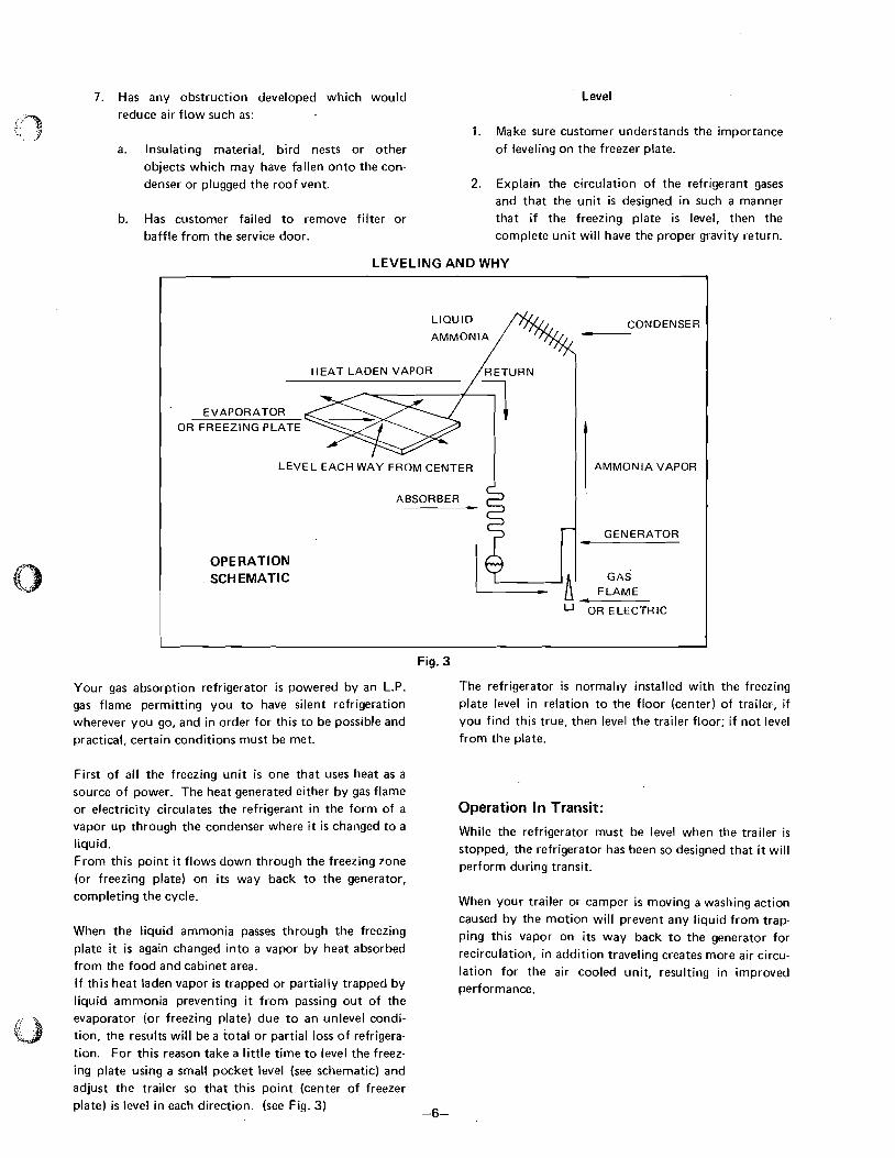
7. Has any obstruction developed - which would Level reduce air flow such as:
1. Make sure customer understands the importance
a. Insulating material, bird nests or other of leveling on the freezer plate. objects which may have fallen onto the con- denser or plugged the roof vent. 2. Explain the circulation of the refrigerant gases
and that the unit i s designed in such a manner
b. Has customer failed to remove filter or that if the freezing plate i s level, then the baffle from the service door. complete unit will have the proper gravity return.
LEVELING AND WHY
CONDENSER - HEAT LADEN VAPOR
EVAPORATOR OR FREEZING PLATE
LEVEL EACH WAY FROM CENTER AMMONIA VAPOR
ABSORBER
GENERATOR *
OPERATION SCHEMATIC
LA OR ELECTRIC
Fig. 3
Your gas absorption refrigerator i s powered by an L.P. The refrigerator i s normally installed with the freezing
gas flame permitting you to have silent refrigeration plate level in relation to the floor (center) of trailer-, if
wherever you go, and in order for this to be possible and you find this true, then level the trailer floor; if not level
practical, certain conditions must be met. from the plate.
First of all the freezing unit i s one that uses heat as a source of power. The heat generated either by gas flame
or electricity circulates the refrigerant in the form of a vapor up through the condenser where it is changed to a liquid. From this point it flows down through the freezing zone
(or freezing plate) on its way back to the generator, completing the cycle.
When the liquid ammonia passes through the freezing plate i t i s again changed into a vapor by heat absorbed from the food and cabinet area. If this heat laden vapor is trapped or partially trapped by liquid ammonia preventing i t from passing out of the
evaporator (or freezing plate) due to an unlevel condi- tion, the results will be a total or partial loss of refrigera- tion. For this reason take a little time to level the freez- ing plate using a small pocket level (see schematic) and
adjust the trailer so that this point (center of freezer plate) i s level in each direction. (see Fig. 3) -6-
Operation In Transit:
While the refrigerator must be level when the trailer is stopped, the refrigerator has been so designed that i t will perform during transit.
when your trailer or camper i s moving a washing action
caused by the motion will prevent any liquid from trap- ping this vapor on its way back to the generator for recirculation, in addition traveling creates more air circu-
lation for the air cooled unit, resulting in improved performance.
4. System Operation
Gas Mode
When GAS SWITCH i s pressed, " G A S ' I ND ICATOR LAMP lights up in green and IGNITION SYSTEM begins to work - giving off continuous sparks between IGNI- TION PLUG and BURNER.
About 10 seconds after GAS SWITCH ON, SOLENOID VALVE will open up and BURNER will let the gas begin flowing. Sparking will stop as soon as the burner i s lit. If the flame goes out for some reason such as being blown out, sparking will begin until the burner is relit. If the burner does not light within 90 seconds after SPARK ON, VALVE is shut off, BUZZER begins ringing and "GAS'INDICATOR LAMP blinks in red. This condition i s called "Lock Out". To release LOCK OUT condition, press OFF SWITCH and then press GAS SWITCH, the series of action (described above) starts again. If the LOCK OUT condi- tion cannot be released by pressing GAS SWITCH repeatedly, refer to TROUBLE SHOOTING HINTS. (Nuisance Lockouts) In regular operation, SOLENOID VALVE and IGNI- TION SYSTEM are controlled (ONIOFF) by thermo- circuit. That is, when thermocircuit is off, burner i s also off. So this type of unit does not require continuous lighting like usual units. (Usual units set the temperature in the box according to the strength of flames.) "GAS'indicator lamp indicates only that the refrigera- tor is in "GAS'mode. Regarding "GAS'mode, "GAS" indicator lamp keeps on lighting up whether thermo- circuit i s on or off.
fi, In this condition, if thermocircuit i s on, AC HEATER FJ'
comes on. The "AC" INDICATOR LAMP indicates only that it is in "AC" mode.
DC Mode (SRAE 0732,1232 only) When CAR IGNITION LOCK SWITCH is on and is connected only with DC POWER SUPPLY (without being connected with AC POWER SUPPLY), if the ELEC. SWITCH i s pressed, "DC" INDICATOR LAMP will light up in green. In this condition, i f thermocircuit i s on, DC HEATER comes on. The "DC" IIVDICATOR LAMP indicates only that i t i s in "DC" mode.
Voltage Check Function
When the voltage of POWER SUPPLY declines (under AC 80V, DC 10.2V) on "GAS" mode, LOCKOUT condition begins. In this case, LOCKOUT will be re- leased without touching the switch when the voltage returns to within the limits of regular functioning (AC 80V -135V. DC 10.2V - 16V). When the voltage goes down (under AC 80V. DC 10.2V) in either "AC" or "DC" mode, both "AC" and "DC" INDICATOR LAMP begin blinking at the same time, BUZZER begins ringing and AC DC HEATER goes off. In this case, regular functioning will resume without touching the switch when the voltage returns to within the limits of regular functioning (AC 80V - 135V, DC10.2V - 16V).
AC Mode
When connecting AC POWER SUPPLY and DC POWER SUPPLY at the same time, AC is connected prior to DC. When ELEC. SWITCH is pressed, "AC" INDICATOR LAMP lights up in green.
5. Installation Instructions For LP Gas Refrigerators $
General Important
Special care i s necessary with the installation of LP gas refrigerators in trailers to ensure, firstly safety in opera- tion, and secondly satisfactory operation under condi- tions that are usually much more difficult than those cases with the normal home installation.
The refrigerator must be installed on a firm floor and must be level. The latter point should be checked by using a spirit level and level both ways in the freezer compartment. A continuous movement, as in the trailers on tow, will not affect the operation if the rolling or pitching passes either side of level.
The operation will be least affected if the refrigerator i s installed with the door parallel to the side wall of the trailer.
Whenever the trailer is parked, careshould be taken that it i s accurately leveled. When parking try to avoid having the wind blowing directly against the wall where the vent outlets are located.
The refrigerator must be securely fixed so that it will not (0 move when the trailer i s in motion, but there should be means of relocating for easy service access.
Screw holes for securing the cabinet to the recess floor
are provided in the cabinet support rails.
An access door on the outside wall a t the back of the refrigerator must be installed for easy servicing.
The LP gas refrigerators are of air-cooled type. w
Therefore i t is of utmost importance that the air circu- lation round the unit parts behind the cabinet i s unrest- ricted. Good refrigeration performance is dependent
upon adequate ventilation of the refrigerator enclosure. This will be achieved by following instructions as shown
in Figs. 4 to 7.
The refrigerator must be completely enclosed at the top,
bottom and sides. All joints in the enclosure must be tight to assure that no combustion products enter into the living area.
Make sure that no part of the vent chimney walls cover the cooling unit and that the louvers in the sidewall vents are obstructed.
Any dead space above the refrigerator should be sealed
off at the rear top corner of the refrigerator cabinet.
All surfaces in the ventilation channel must be protected with a fire resistant material.
Some methods of installation are shown in Figs. 4 - 7. Each method has the inlet vent located on the side of
the trailer or mobile home.
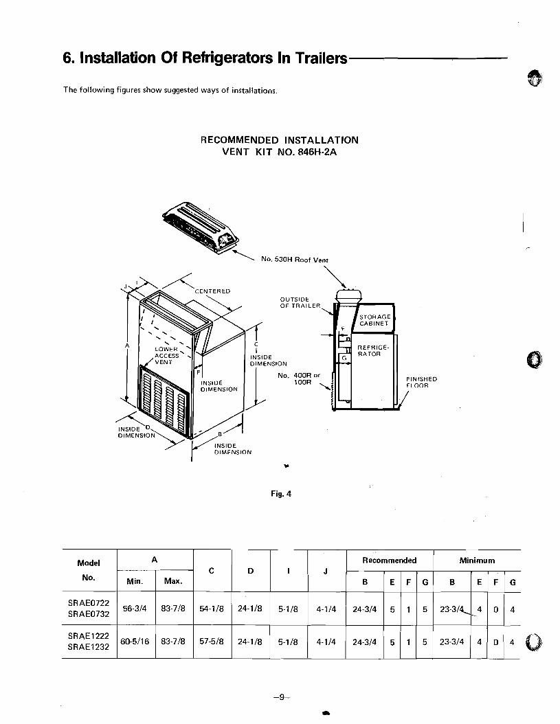
6. Installation Of Refrigerators In Trailers
The following figures show suggested ways of installations.
RECOMMENDED INSTALLATION VENT KIT NO. 846H-2A
- \ No. 530H Roof Vent
OUTSIDE O F TRAILER
\ .
No. 400R or 1 OOR
.,
Fig. 4
Model
No.
SR AE0722 SRAE0732
1222 SRAE1232
A C
54-118
57-518
Min.
56-314
60-5116
Max.
83-718
83-718
D
24-118
24-118
I
5-118
5-118
J
4-114
4-114
Recommended
B
24-314
24-314
Minimum
B
23-3/<
23-314
5
5
4 .
4
E F G
1
1
E F G
0
0
5
5
4
4

ALTERNATE INSTALLATION VENT KIT NO. 746H-5
OUTSIDE OF TRAILER
\
NO. 400R or 1 OOR
Fig. 5
C
54-1 18
Model
No.
SRAE0732
D
24-118
J
4-114
I
5-1 18
A
Min.
56-314
Max.
83.718
Recommended
B
24-314
Minimum
B
23-314 5 4
E F G
1 5
E F G
0 4
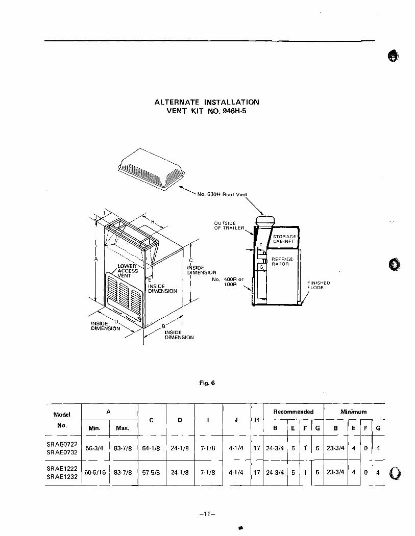
ALTERNATE INSTALLATION VENT KIT NO. 946H-5
' NO. 630H Roof Vent
. S 1 ' INSIDE DIMENSION
No.
SIDE MENSION
Fig. 6
TSlDE TRAIL
400R 1 OOR
H
17
17
J
4-114
4-114
Model
No.
SRAE0722 SRAE0732
SRAE1222 SRAE1232
Recommended A
B
24-314
24-314
Minimum
Min.
56-314
60-5116
I
7-118
7-118
C
54-1 18
57-518
B
23-314
23-314
Max.
83-718
83-718
D
24-118
24-118
5
5
4
4
5
5
E F G
1
1
E F G
0
0
4
4
P
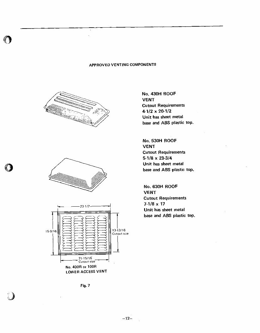
APPROVED VENTING COMPONENTS
1- 21.15116 4 Cutout s u e
No. 400R or 100R LOWER ACCESS VENT
No. 430H ROOF VENT Cutout Requirements 4-112 x 20-112 Unit has sheet metal base and ABS plastic top.
No. 530H ROOF VENT Cutout Requirements 5-118 x 23-314 Unit has sheet metal base and ABS plastic top.
No. 630H ROOF VENT Cutout Requirements 7-118 x 17 Unit has sheet metal base and ABS plastic top.
Fig. 7
7. Gas Line
LP gas i s highly inflammable and i t is of extreme impor- tance to ensure not only that all joints in piping carrying the gas from the storage bottle to the appliances burning are - and will remain - absolutely gas tight, but that
any non-metallic packings used in such joints are made from materials that will not deteriorate from contact with LP gas.
The gas line should be free of kinks and sharp bends.
After installation, the gas should be turned on, and all joints in the gas line must be checked for leaks up to the burner by use of soap and water solution. This check
should be exercised periodically.
Do not f it any extension to the top of the flue. This i s not only unnecessary, but can create draught conditions which can adversely affect correct combus- tion at the burner and consequently, the functioning of
the cooling unit.
The refrigerator should be operated at an inlet gas
pressure of 11" W.C. (2.75 kPa). Refer to Para. 13.
Incoming gas pressure is controlled by the pressure regulator on the propanelbutane bottle.
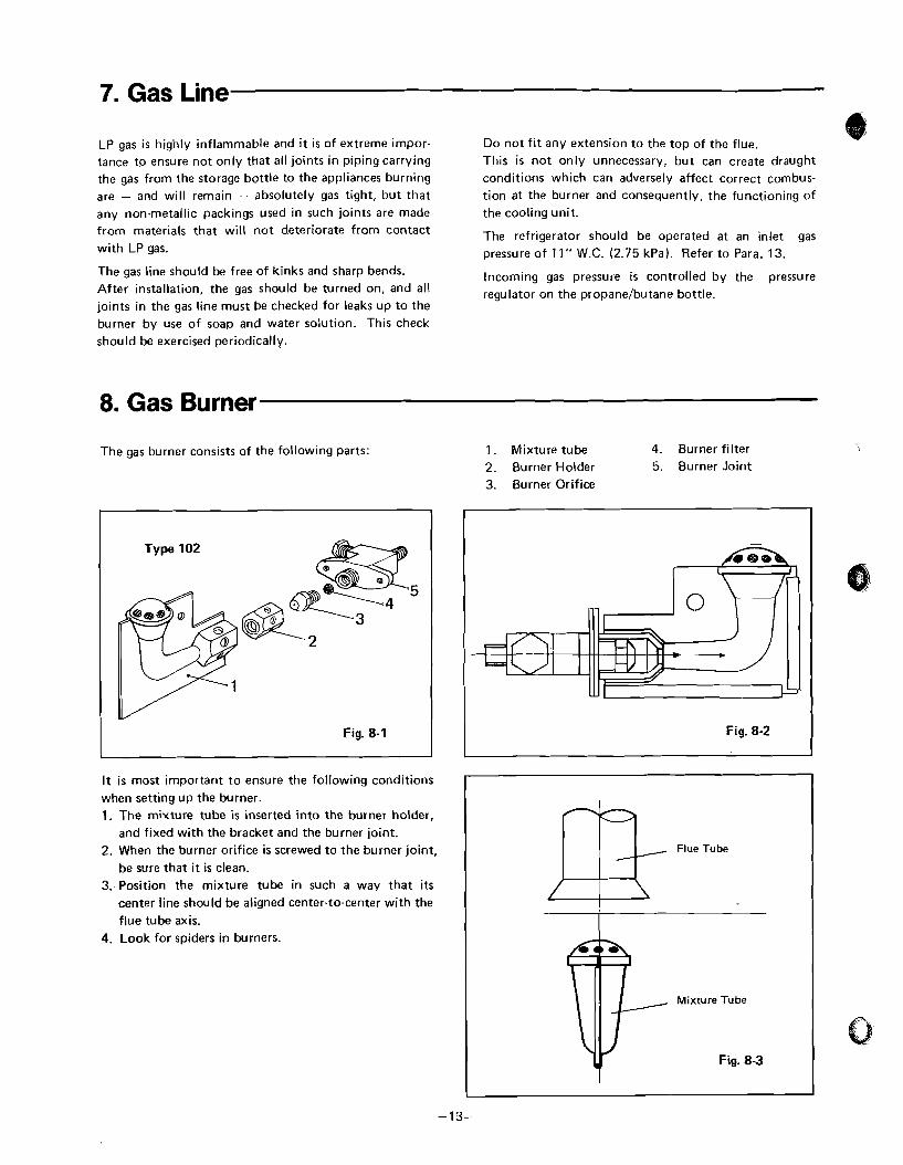
8. Gas Burner
The gas burner consists of the following parts:
Type 102
5
Fig. 8-1
It i s most important to ensure the following conditions when setting up the burner. 1. The mixture tube is inserted into the burner holder,
and fixed with the bracket and the burner joint. 2. When the burner orifice is screwed to the burner joint,
be sure that it is clean. 3. Position the mixture tube in such a way that i t s
center line should be aligned center-to-center with the
flue tube axis.
4. Look for spiders in burners.
1. Mixture tube 4. Burner filter 2. Burner Holder 5, Burner Joint 3. Burner Orifice
-
Fig. 8-2
Q ..
Flue Tube
Mixture Tube
t Fig. 8-3
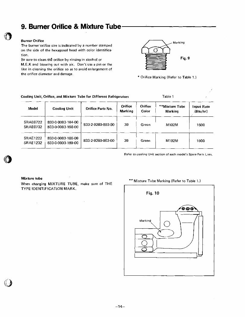
9. Burner Orifice & Mixture Tube ( i $
Burner Orifice The burner'orifice size i s indicated by a number stamped on the side of the hexagonal head with color identifica- tion. Be sure to clean the' orifice by rinsing in alcohol or M.E.K and blowing out with air. Don't use a pin or the like in cleaning the orifice so as to avoid enlargement of
Mark ing
Fig.
the orifice diameter and damage. * Orifice Marking (Refer to Table 1 .)
Cooling Unit, Orifice, and Mixture Tube for Different Refrigerators Table 1
Model Cooling Unit Orifice Parts No. Orifice Orifice **Mixture Tube Input Rate I Marking / Color I Marking I (Btuihr)
SRAE0722 SRAE0732
Refer t o coo l ing U n i t sect ion o f each model's Spare Parts Lists.
SR AE 1222 SRAE1232
Mixture tube
When changing MIXTURE TUBE, make sure of THE
833-0-0003- 184-00 833-0-0003-198-00
TYPE IDENTIFICATION -MARK.
833-0-0003- 185-00 833-0-0003-1 99-00
** Mixture Tube Marking (Refer to Table 1.)
833-2-9260-003~00
7
Fig. 10
833-2~9260~003-00
39
39
Green
Green
M102M 1600
M102M 1600

10. Burner Orifice Clogged
When the burner orifice is clogged, the flame will be- come too small which may affect the burner heating output and result in decrease of cooling efficiency. For taking out the clog or replacing the burner orifice, refer t o Figs. 11 -1 through 11-4.
b lowaut cover
Fig. 11-1 Remove the flame blow-out cover from the refrigerator by unscrewing 2 screws.
Fig. 11-2 Remove the box nut of the gas pipe from the burner joint. (Turn the
nut counterclockwise.)
-
Fig. 11-3 Take of f the burner joint out of the burner bracket. (Unscrew 2 screws)
Fig. 11-4 Take out the orifice from the
burner joint. (Turn the orifice counterclockwise.)
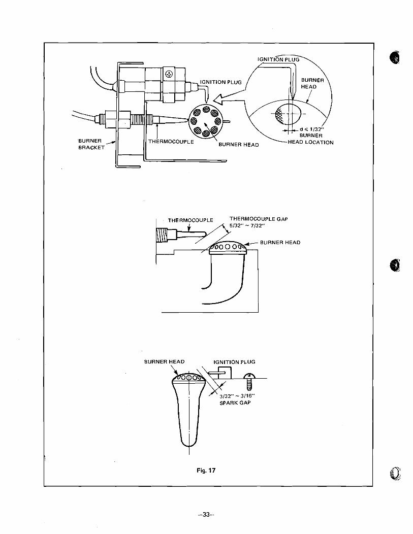
11. Check Of The Ignition Plug & Thermocouple ~(9
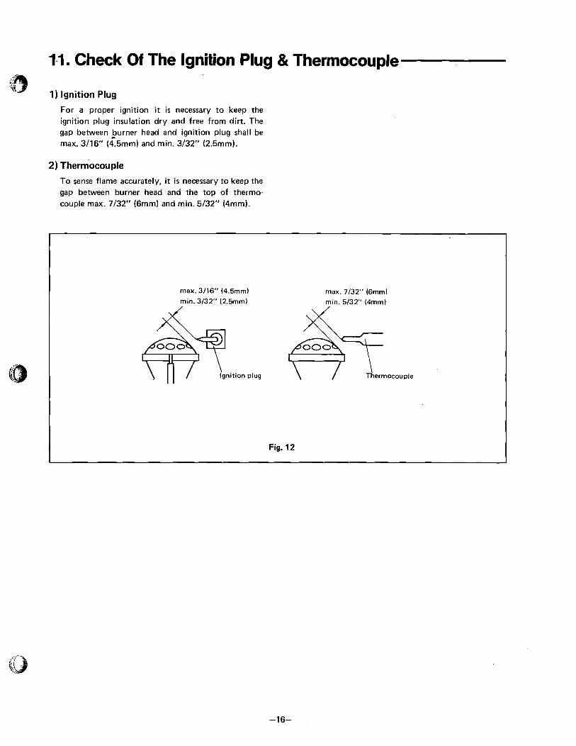
1) Ignition Plug
For a proper ignition i t i s necessary to keep the ignition plug insulation dry and free from dirt. The gap between iurner head and ignition plug shall be rnax. 3/16" (4.5mm) and rnin. 3/32" (2.5rnm).
2) Thermocouple
To sense flame accurately, it i s necessary to keep the
gap between burner head and the top of thermo- couple rnax. 7/32" (6rnrn) and rnin. 5/32" (4mrn).
max. 3/16" (4.5mm) max. 7/32" (6mmJ mln. 3/32" (2.5mm) min. 5/32" (4mmJ & &
Ignition plug Thermocouple
Fig. 12
12. Flue System
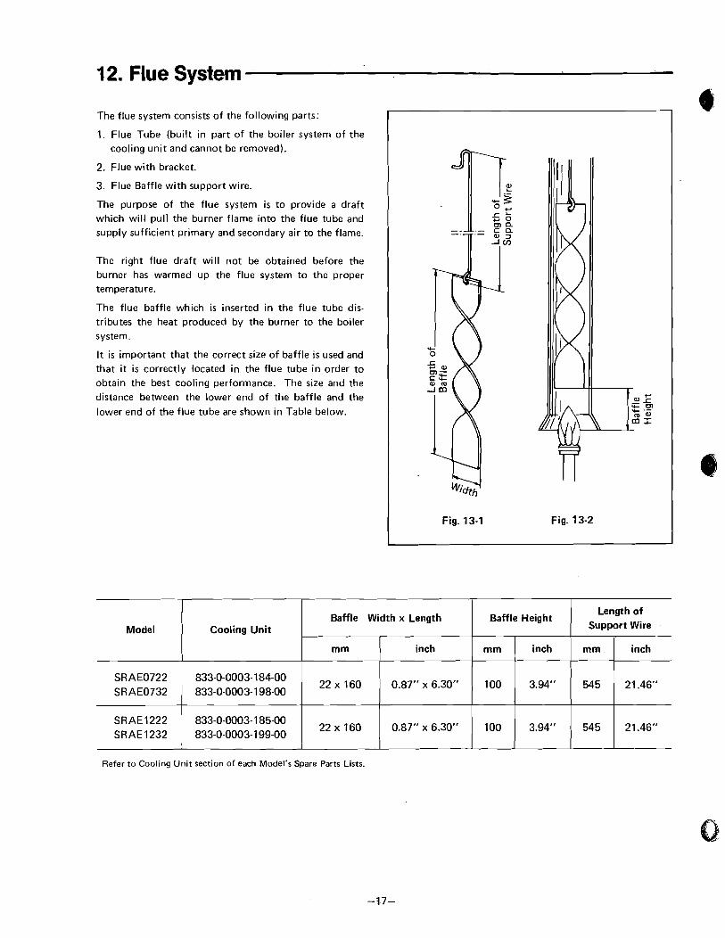
The flue system consists of the following parts:
1. Flue Tube (built in part of the boiler system of the cooling unit and cannot be removed).
2. Flue with bracket.
3. Flue Baffle with support wire.
The purpose of the flue system is to provide a draft which will pull the burner flame into the flue tube and
supply sufficient primary and secondary air to the flame.
The right flue draft will not be obtained before the
burner has warmed up the flue system to the proper temperature.
The flue baffle which is inserted in the flue tube dis- tributes the heat produced by the burner to the boiler system.
It is important that the correct size of baffle i s used and that i t is correctly located in the flue tube in order to
obtain the best cooling performance. The size and the distance between the lower end of the baffle and the
lower end of the flue tube are shown in Table below.
Fig. 13-1 Fig. 13-2
Refer to Cooling Unit section of each Model's Spare Parts Lists.
Model
SRAE0722 SRAE0732
SRAE1222 SR AE 1232
Length of Support Wire Cooling Unit
833-0-0003-184-00 833-0-0003-1 98-00
833-0-0003-1 85-00 833-0-0003-1 99-00
mm.
545
545
Baffle Width x Length
inch
21.46"
21.46"
Baffle Height
mm
22 60
22 60
mm
100
100
inch
0.87" x 6.30"
0.87" x 6.30"
inch
3.94"
3.94"
13. Pressure Measuring Devices $3
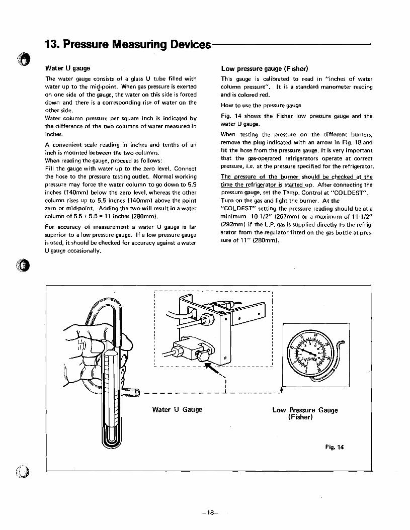
Water U gauge ,
The water gauge consists of a glass U tube filled with water up to the mi(-point. When gas pressure is exerted on one side of the gauge, the water on this side is forced down and there is a corresponding rise of water on the other side. Water column pressure per square inch is indicated by the difference of the two columns of water measured in inches.
A convenient scale reading in inches and tenths of an inch is mounted between the two columns. When reading the gauge, proceed as follows: Fill the gauge with water up to the zero level. Connect the hose to the pressure testing outlet. Normal working pressure may force the water column to go down to 5.5 inches (140mm) below the zero level, whereas the other column rises up to 5.5 inches (140mm) above the point zero or mid-point. Adding the two will result in a water column of 5.5 + 5.5 = 11 inches (280mm).
For accuracy of measurement a water U gauge is far superior to a low pressure gauge. I f a low pressure gauge is used, it should be checked for accuracy against a water U gauge occasionally.
Low pressure gauge (Fisher) This gauge is calibrated to read in "inches of water column pressure". It i s a standard manometer reading and i s colored red.
How to use the pressure gauge
Fig. 14 shows the Fisher low pressure gauge and the water U gauge.
When testing the pressure on the different burners, remove the plug indicated with an arrow in Fig. 18and f i t the hose from the pressure gauge. It is very important that the gas-operated refrigerators operate a t correct pressure, i.e. a t the pressure specified for the refrigerator.
The pressure of the burner should be checked a t the time the refrigerator i s started up. After connecting the pressure gauge, set the Temp. Control a t "COLDEST". Turn on the gas and light the burner. At the "COLDEST" setting the pressure reading should be a t a minimum 10-112" (267mm) or a maximum of 11-112" (292mm) if the L.P. gas i s supplied directly t c ~ the refrig- erator from the regulator fitted on the gas bottle a t pres- sure of 11" (280mm).
,-- - - - - - - - - - - - - - - - - - - - - - - - I I I I I
I I I I I I I I I 4
0
I I I - - - - - - -
\
I I
-,-----,-- 1 - - - - - - - - - -
Water U Gauge Low Pressure Gauge (Fisher)
Fig. 14
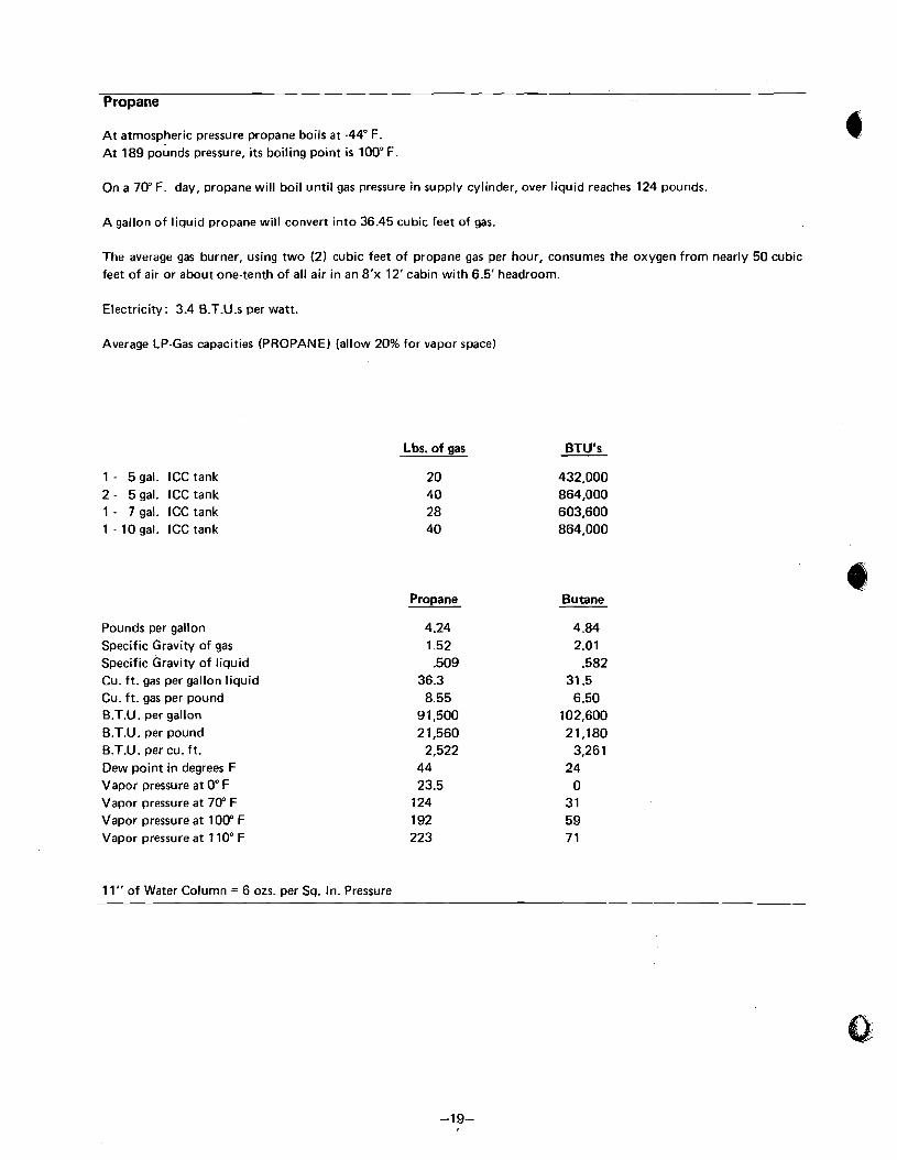
Propane
At atmospheric pressure propane boils at -44" F. At 189 pounds pressure, its boiling point is 100" F
On a 70" F. day, propane will boil until gas pressure in supply cylinder, over liquid reaches 124 pounds.
A gallon of liquid propane will convert into 36.45 cubic feet of gas.
The average gas burner, using two (2) cubic feet of propane gas per hour, consumes the oxygen from nearly 50 cubic feet of air or about one-tenth of all air in an 8'x 12'cabin with 6.5' headroom.
Electricity: 3.4 6.T.U.s per watt.
Average LP-Gas capacities (PROPANE) (allow 20% for vapor space)
1 - 5 gal. ICC tank 2 - 5 gal. ICC tank 1 - 7 gal. ICC tank 1 - 10 gal. ICC tank
Pounds per gallon Specific Gravity of gas Specific Gravity of liquid Cu. f t . gas per gallon liquid Cu. ft. gas per pound B.T.U. per gallon B.T.U. per pound B.T.U. per cu. ft. Dew point in degrees F Vapor pressure at O" F Vapor pressure at 700 F Vapor pressure at 100" F Vapor pressure at 110' F
11" of Water Column = 6 02s. per Sq. In. Pressure
Lbs. of gas
Propane
4.24 1.52 .509
36.3 8.55
9 1,500 2 1,560
2,522 44 23.5
124 192 223
Butane
4.84 2.01
.582 31.5 6.50
102,600 21,180
3,26 1 24
0 31 59 7 1
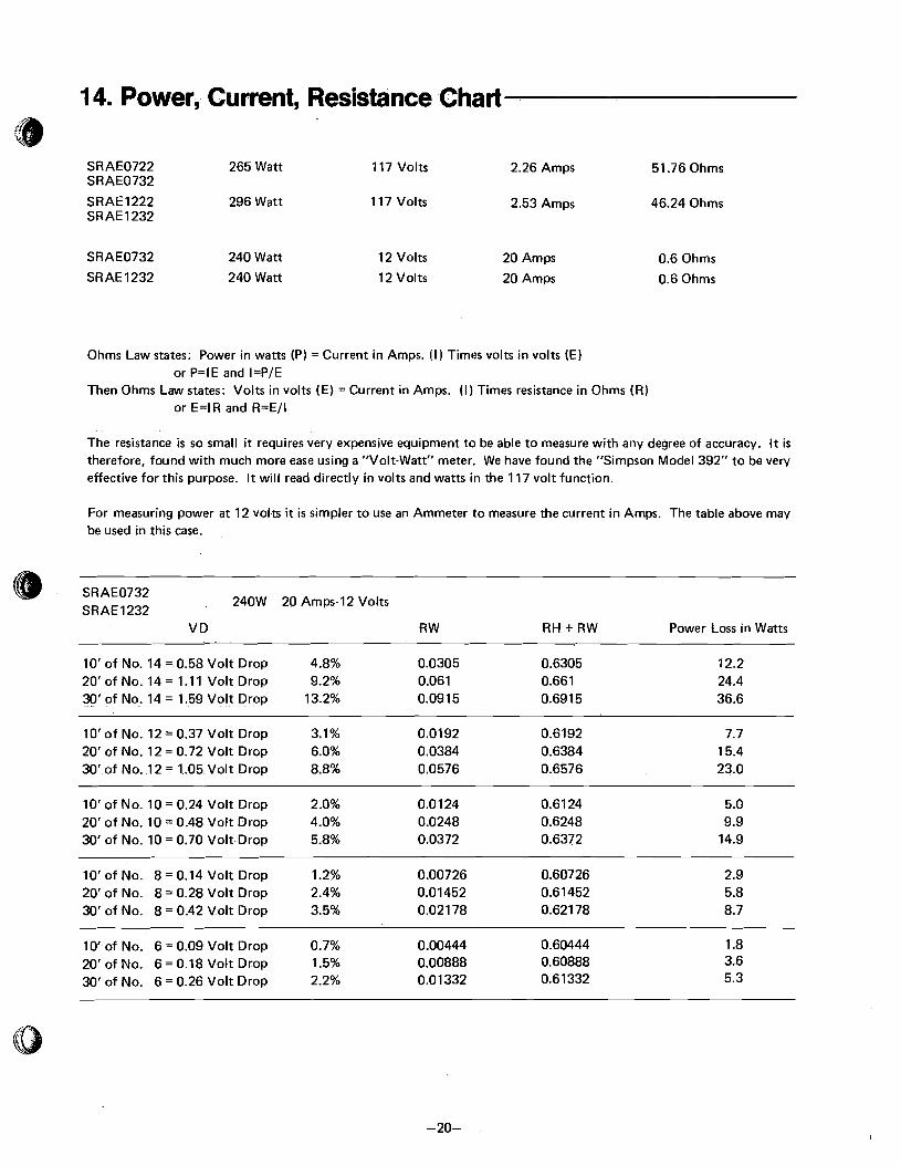
1 4. Power, Current, Resistance Chart
265 Watt 11 7 Volts 2.26 Amps 51.76 Ohms
SRAE1222 296 Watt 117 Volts 2.53 Amps 46.24 Ohms SR AE 1232
SRAE0732 240 Watt
SR AE 1232 240 Watt
12 Volts 20 Amps
12 Volts 20 Amps
0.6 Ohms
0.6 Ohms
Ohms Law states: Power in watts (P) = Current in Amps. (I) Times volts in volts (E) or P=IE and I=P/E
Then Ohms Law states: Volts in volts (E) = Current in Amps. (I) Times resistance in Ohms (R) or E=IR and R=E/I
The resistance is so small it requires very expensive equipment to be able to measure with any degree of accuracy. It is therefore, found with much more ease using a "Volt-Watt" meter. We have found the "Simpson Model 392" to be very effective for this purpose. It will read directly in volts and watts in the 117 volt function.
For measuring power a t 12 volts it i s simpler to use an Ammeter to measure the current in Amps. The table above may be used in this case.
@ SRAE0732 SRAE1232
240W 20 Amps-12 Volts
VD RW RH + RW Power Loss in Watts
10' of No. 14 = 0.58 Volt Drop 4.8% 0.0305 0.6305 20'of No. 14 = 1.11 Volt Drop 9.2% 0.061 0.661 30' of No. 14 = 1.59 Volt Drop 13.2% 0.09 15 0.6915
10' of No. 12 = 0.37 Volt Drop 3.1% 0.0192 0.6192 7.7 20' of No. 12 = 0.72 Volt Drop 6.0% 0.0384 0.6384 15.4 30' of No. 12 = 1.05 Volt Drop 8.8% 0.0576 0.6576 23.0
10' of No. 10 = 0.24 Volt Drop 2.0% 0.0 124 0.6124 5.0 20' of No. 10 = 0.48 Volt Drop 4.0% 0.0248 0.6248 9.9 30' of No. 10 = 0.70 Volt Drop 5.8% 0.0372 0.6372 14.9
10' of No. 8 = 0.14 Volt Drop 1.2% 0.00726 0.60726 2.9 20' of No. 8 = 0.28 Volt Drop 2.4% 0.01452 0.6 1452 5.8 30' of No. 8 = 0.42 Volt Drop 3.5% 0.021 78 0.621 78 8.7
10' of No. 6 = 0.09 Volt Drop 0.7% 0.00444 0.60444 1.8 20' of No. 6 = 0.18 Volt Drop 1.5% 0.00888 0.60888 3.6 30' of No. 6 = 0.26 Volt Drop 2.2% 0.01 332 0.61332 5.3

15. Heating Elements For Different Refrigerators
16. Leveling
SRAE0722
SRAE0732
S RAE 1222
SRAE 1232
In the boilei of the cooling unit, ammonia vapor i s dis- tilled from an ammonia-water mixture and carried to the finned condenser where it liquefies. The liquid flows to the evaporator inside the cabinet where it cools, evapo- rating into a circulating flow of hydrogen gas. I f the evaporator i s not level the liquid readily accumulates, forming pockets which can impair the gas circulation or block it completely, resulting in suspension of cooling action.
When the trailer i s stationary, it must be leveled to be comfortable to live in. I f the refrigerator i s properly installed, i.e. the ice-tray compartment shelf i s parallel with the floor, the refrigerator will operate properly.
With the level placed on the ice-tray compartment shelt, and check to see the position of the bubble (if necessary, with the aid of a small mirror). Adjust the position of the trailer so that the bubble i s in the center ring of the level.
When the trailer i s on tow, the continuous rolling and pitching movement will not affect the refrigerator as long as the movement passes either side of level but
F when the trailer is temporarily parked, the sensitivity of the refrigerator should be kept in mind.
Refer to Cooling Unit section of each Model's Spare Parts Lists.
833-0-0003-1 84-00
833-0-0003- 198-00
833-0-0003- 185-00
833-0-0003-1 99-00
1 7. Temperature Control
a) When the Temp. control i s set at colder setting, b) The setting position of the Temp. control should
refrigerating effect will be increased. This will tend depend upon the refrigerator load. t o lower the temperature in the freezing compart- When the food load i s heavy, slide the Temp. ment and in the food storage compartment. control to the colder setting. When the Temp. control is set at middle position, The colder setting of the Temp. control will be medium refrigerating effect will be produced. required in summer than in winter season.
The setting of the Temp. control determines the action of the Temp. control in relation t o food storage compartment temperatures.
4-2459-432-34
4-2459-432-32
4-2459-432-33
4-2459-432-31
265
AC265, DC240
296
AC296, DC240
AC117
AC? 17, DC12
AC117
AC117, DC12

18. Thermal Sensor j .
-4. 6 The thermal sensor must be fastened on the holder lo- cated at the evaporator. See Fig-24. If the thermal sensor i s not properly fastened on the holder, the burner will operate continuously a t maximum flame. It will cause too low cabinet temperatures.
19. Storing Food In The Refrigerator
a) Proper refrigeration requires free air circulation within the food storage compartment. Restricted air circulation within the food storage compartment will cause higher cabinet temperatures. Rearrange foods.
b) It is also essential that the shelves are not covered with paper or large storage containers.
d) To reduce frost formation in and on the freezing compartment, cover stored liquids and moist foods and do not leave the door open longer than neces- sary.
el When the refrigerator i s heavily loaded, it takes longer for refrigerator temperatures to lower, requir- ing much longer time for ice-making. A very heavy load may also cause defrosting.
c) Odorous foods or highly flavored foods should always be stored in covered dishes, plastic bags or wrapped in foil or waxed paper, to prevent food odors. Vegetables, lettuce, etc., should be covered to retain their crispness. Never put hot food into the refrigerator.
20. Cleaning
The cabinet interior should be cleaned regularly. Plastic dishes may be washed in warm soapy water - not Wash the lining with lukewarm water to which a little hotter than is bearable to the hand. soap flakes may be added. Dry thoroughly, especially Do not expose them to dry heat. Never use strong chem- around door frames and door gasket. Warm water only icals or abrasive cleaning materials on any part of the should be used to wash the cooling evaporator, ice-trays cabinet. and shelves.
21. Ice Cubes
a) Do not use warm water, as it takes longer to freeze. b) Faster freezing will result i f precooled water is used.
22. Travel Lock
The travel latch may be fitted to hold door(s) closed (D while in transit.

23. To Shut Off The Cabinet
If for any reason refrigeration i s not required over a The cabinet and ice trays should be emptied, cleaned period of weeks, press OFF MODE SWITCH to stop the and dried.
operation of the refrigerater, and fully close MANUAL It i s advisable to keep the door open a little when not in
VALVE on the back of unit. use for longer period of time.
24. Door Seal
a) It i s essential, for correct operation, that the door gasket makes a good seal all around, against the front of the cabinet.
The gasket should just contact the front of the cabinet when the door i s closed. This i s normaly allowed for during manufacturing.
Failure of the door gasket to contact the front of the cabinet can be determined visually when the door i s closed. Run a piece of thin cardboard along the door seal, inserted between the gasket and the cabinet front. Nowhere should the card feel loose.
25. Flue Obstructions
On gas refrigerators, the flue will requires occasional cleaning. To do this it will be necessary to gain access to the back of the cabinet. When cleaning the flue proceed as follows:
Unscrew the flame blow-out guard. Cover the entire burner assembly (See Figs. 11 -1 through 11 4) with a piece of rag, then l ift out the baffle on i t s support wire from the top of the flue tube.
b) Improper door sealing on cabinets provided with magnetic door gasket can be corrected by slackening the upper and lower hinge fixing screws and moving the door inwards or outwards by inserting or remov- ing a washer to correct the door as required until a satisfactory seal is obtained. If good seal cannot be obtained, a new gasket should be fitted.
c) It i s also essential to check that the cabinet opening through which the freezing compartment enters the cabinet should be properly sealed by a gasket. I f these seals leak, warm air enters the cabinet causing high cabinet temperatures and excessive frost for- mation on the freezing compartment.
From the top, clean the flue with a suitable flue brush. Also clean the baffle, before putting back in place.
An obstruction in the flue will reduce or stop flue draft. Flue obstructions will cause odors outside refrigerator, slow freezing and higher cabinet temperatures. Flue blockage may also cause the flame to burn outside the flue tube.
26. Odors Inside The Refrigerator
Odors inside the refrigerator are caused by improper They may also be caused by too infrequent cleaning of food storage (See para. 19). the food compartment or the refrigerator has been shut
off for some time with the door closed.

27. Odors From Fumes
a) Odors outside the refrigerator may be caused by gas b) Odors outside the refrigerator may be caused by
leaks. Make sure that all burner gas valve on all gas improper burner flame.
appliances are closed. c) The flame touches side of the flue tube due to dis- Test gas connections and all joints in the gas line with location of the burner. Relocate. soap and water solution, up to and including manual Burner dislocation may also cause smoking and soot- valve. Never look for a leak with an open flame. Use a ing of walls and ceiling. flashlight when necessary in looking for soap bubbles caused by leaks. The gas line should be free of kinks d) Burner damaged. Replace.
and sharp bends. e) The flame touches flue baffle. Correct position of
Turn on manual valve, light bruner and test connec- baffle.
tions between the manual valve and the burner care- f ) The flue tube i s dirty. Ctean the flue. fully with soap and water. Turn to Fig. 8-3.
28. Operation Analysis For Cooling Unit
I t is obviously important that all external factors affect- ing the unit should be checked properly before a unit i s condemned as faulty and that emphasis has been placed upon the necessity for correct installation, upright refrig- erator, correct heat input, baffle position, etc. If the re- frigerator i s the gasfelectric model, check the size and the wattage of the electric heater and make sure that the heater element i s inserted to its full length in its pocket or receptacle. See Fig. 19. If the electric heater i s only partly inserted, the heat distribution will be incorrect, causing an excessive vaporizing of the ammonia within the boiler when operating on electricity. The same symptom can show up with too much or too little heat input either on electric or on gas operation and also if the refrigerator had been operating in an off-level posi- tion or with inadequate ventilation.
If an excessive vaporizing of the ammonia within the boiler occurs due to the above causes, the liquid mixture in the boiler becomes very weak and the pump will cease to operate, which means that the circulation of liquid
the liquid in the absorber vessel can be mixed with the liquid in the boiler. This procedure will restore the liquid balance in the unit. Start the unit on "COLDEST".
The temperatures on various parts of a unit vary contin- uously when i t i s operating on thermostatic control and i t i s impossible to base a judgement on the symptoms given unless the refrigerator has been operating contin- uously on fully correct heat input for at least 5 hours, and preferably 12 hours, prior to examination. In many cases this can be arranged by a telephone call to the customer, asking him to switch the Temp. control to "COLDEST" on the day before the inspection call. If after 12 hours' operation on "COLDEST", the perform- ance is satisfactory, the unit i s not at fault unless the complaint i s one of varying or intermittent performance. In this connection the room temperature at the time of the complaint must be considered, as a unit which i s satisfactory at an ambient temperature of 5 0 ' ~ may not be satisfactory at 95OF.
stops with the result that the evaporator inside the In cases where satisfactory performance is obtained on cabinet ceases to produce cooling. "COLDEST" but not on other settings, the Temp. Such a blockage of the unit in the liquid circuit i s most usually made evident by signs of overheating on the vapour pipe leading from the boiler to the condenser, the paint on this pipe being blistered and the metal be- coming discoloured.
To remedy this fault i t i s recommended to remove the unit or refrigerator complete whenever possible and to allow sufficient time to cool down the unit. Turn the unit or refrigerator upside down several times, so that
control i s to be suspected.
When a normal unit i s working on "COLDEST" the absorber coil will be warmer at the bottom than at the top. The absorber vessel will be warmer. The vapor cooling pipe from the boiler to the condenser will be warm, bearable to the hand, at the bend where i t joins the condenser, with a gradual rise in temperature towards the boiler end.

29. Unit Filling Valve
The needle valve used for admitting the filling charge to Unsatisfactory unit performance due to an ammonia a cooling unit i s fitted to the unit's absorber vessel and i s leak can be determined in the case of a visible leak by covered by a plastic cap. It i s strictly applied provision traces of a yellow deposit at the point where the of the warranty extended on the unit to the customer, ammonia i s bleeding. If there i s a leak on the evaporator the any interference with the filling valve will automati- inside the cabinet, ammonia smell may result. cally void the warranty.
30. Things To Do Before Sending Back Defective Units To Distributor
Leveling of the refrigerator
Ventilation
Cleaning.and proper size of burner orifice
Correct burner air adjustment
Proper gas pressure
Correct height of flame
Correct position of baffle in flue tube
No burnt-out heating element
Heating element in correct position
Correct size and wattage of heating element
Supply voltage corresponds to voltage stamped on
heating element
No fluctuation in voltage supply
No loose electric connections
No unit leaks
31. Packing Of Defective Units
Particular attention must be paid to the packing of a of wood bracing and cardboard pads, is used when the replaced defective unit to ensure, during its return to the defective unit i s packed into the case. distributor, that i t will not be damaged in transit. Structural distortion may occur if the case containing When the replacement unit i s supplied cased, careful the unit is roughly handled and i f internal braces are not note should be taken of the manner in which i t i s packed, in position. to ensure that the form of packing adopted, i.e. the use
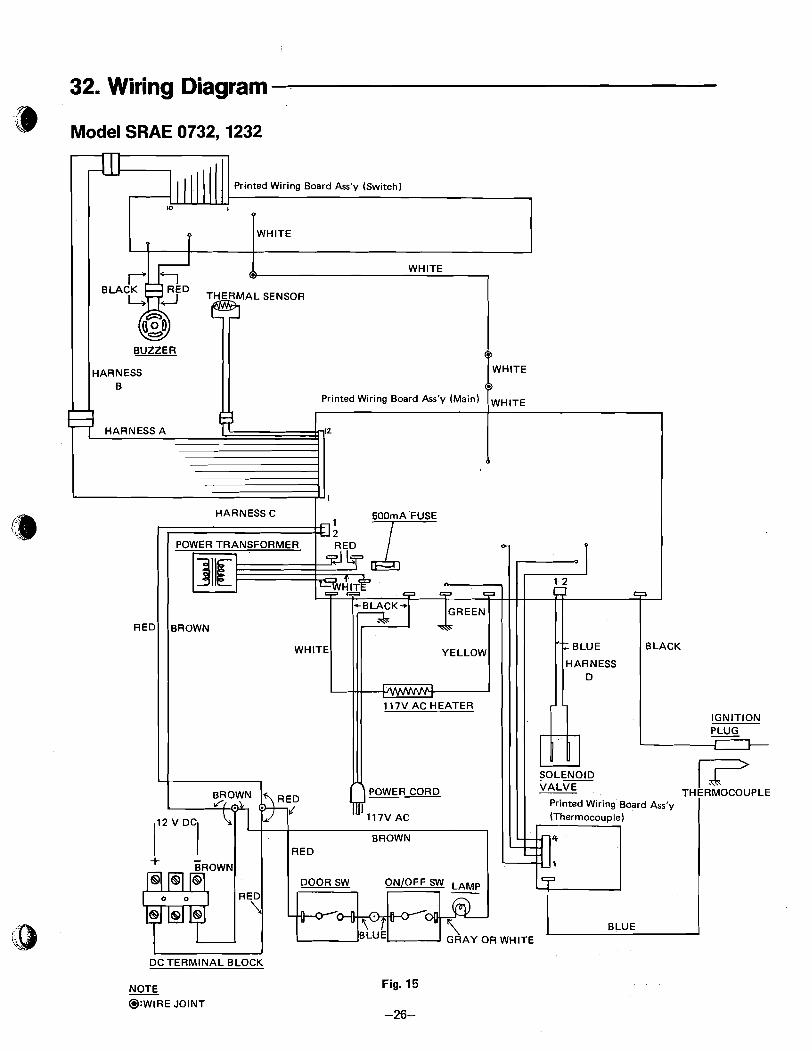
32. Wiring Diagram
Model SRAE 0732,1232
- DC TERMINAL BLOCK
NOTE @:WIRE JOINT
Fig. 15
-26-

Model SRAE 0722,1222
IGNITION
POWER CORD Printed Wiring Board
DC TERMINAL BLOCK
NOTE
@:WIRE JOINT Fig. 16
-27-
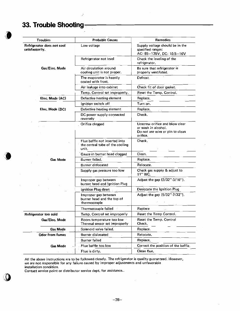
33. Trouble Shooting
Troubles
GasIElec. Mode Air circulation around Be sure that refrigerator is cooling unit is not proper. properly ventilated.
Refrigerator does not cool satisfactorily.
The evaporator is heavily I coated with frost.
Probable Causes
1 Defrost.
Remedies
Low voltage
Refrigerator not level
Supply voltage should be in the specified ranges: AC: 85-1 35V. DC: 10.5-1 6V Check the leveling of the refriqerator.
I lqnition switch off I Turn on.
Elec. Mode (AC)
Unscrew orifice and blow clear or wash in alcohol. Do not use wire or pin to clean orifice.
Air leakage into cabinet
Temp. Control set improperly.
Defective heating element
Elec. Mode (DC)
Check f i t of door gasket.
Reset the Temp. Control.
Replace.
Gas Mode I Burner failed. I Replace.
Defective heating element
DC power supply connected reversely
Flue baffle not inserted into the central tube of the cooling unit.
Gauze in burner head clogged
I Burner dislocated I Relocate.
-
~ e ~ l a c e .
Check.
Check.
Clean.
Supply gas pressure too low 1 Check gas supply &adjust to 11" WC.
Improper gap between I Adjust the gap (3/32"-3/16"). burner head and lgnition Plug
Ignition Plug dews
Improper gap between burner head and the top of thermocouple
Odor from fumes I Burner dislocated I Relocate.
Desiccate the Ignition Plug
Adjust the gap (5132"-7/32").
Refrigerator too cold
GasIElec. Mode
Gas Mode
All the above instructions are to be followed closely. The refrigerator i s quality-guaranteed. However, we are not responsible for any failure caused by improper adjustments and unfavorable installation condition. Contact service point or distributor service dept. for assistance..
Thermocouple failed
Temp. Control set improperly
Room temperature too low Thermal sensor set improperly
Solenoid valve failed.
Gas Mode -
,
Replace
Reset the Temp Control.
Reset the Temp. Control Check.
Replace.
Burner failed
Flue baffle too low
Flue is dirty.
- -
Replace.
Correct the position of the baffle.
Clean flue.

Flame Fails To Ignite-Gas Mode (Check With Gas Mode Switch ON)
NO
I YES
NO
Trouble Shooting Chart
Gas In Tanks? Line Valve Open? Manual Valve Open? Gas Pressure Ok?
NO - Ignition Wire [Harness H) YES - In Place And In Good Condition?
Printed Wiring Board Ass'y (Main) CN13 And Ground?
yr Is Temp. Control Ok? See Temp. Control Check Out Procedure
7 12V DC Present Across Spark Gap Correct? , 1 Solenoid Valve Terminals? See Fig-1 7
YES
e Wiring Board Ass'y (Main)
Correct Or Replace Ignition Plug Replace Printed
Wiring Board Ass'y
Plugged Or Dir ty Replace
C I
t Replace Solenoid Valve Clean Or Replace As Needed I
'Ignition Plug O.K.? Spark Gap Correct? (Ceramic Not Cracked Etc.) See Fig. 17 1
Correct * lgnition Plug Dews? P C
Replace Printed Wiring Board Ass'y (Main) Desiccate +

Flame Ignites But Goes Into Lockout Repeatedly Nuisance Lockouts
'# (Check With Gas Switch "ON") '
\
Correct Or Replace I
NO Is Therrnocouple Wire I n Place? Is Therrnocouple Wire I n Good Condition? YES (Check Continuity, Etc)
b
NO YES + - Is Thermocouple Mounted Tightly to Burner Bracket? -
Tighten Mounting Screws I 1
NO
I Correct Or Replace
I Clean Or Replace I i
Is Thermocouple Free Of Carbon Build Up?
YES + - NO + Is Flame Noisy Or Lifting From Burner Head?
YES
b .
YES -
Is Thermocouple Wire Touching Any Metal Parts?
Check For Blockage Of Primary Air Holes In Bunner Tube See Fig. 17 I
NO
b NO Is Thermocouple Properly Located In YES Flame?
Is Gas Pressure O.K.?
YES I + Correct Or Replace See Fig. 17 -
I I Correct Pressure Setting
v - Replace Printed Wiring Board Ass'y (Thermocouple)
TJ
I I
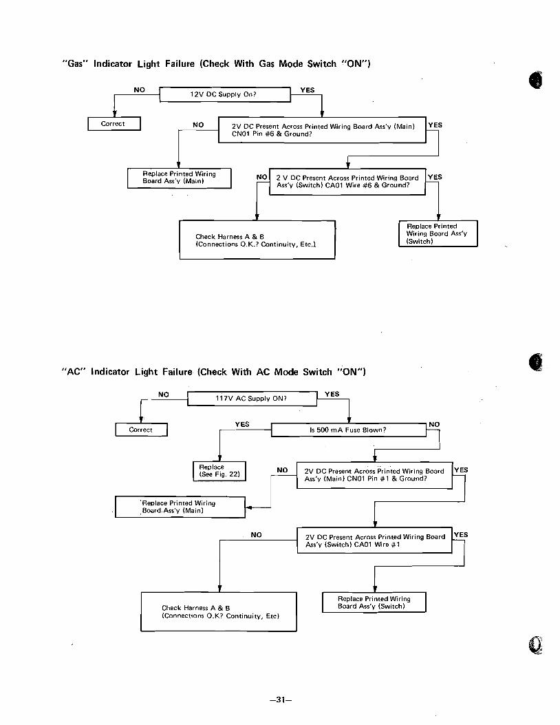
"Gas" lndicator Light Failure (Check With Gas Mode Switch "ON")
+ NO 2V DC Present Across Printed Wiring Board Ass'y (Main) YES
r C N O ~ Pin #6 & Ground?
NO 12V DC Supply On?
Replace Printed Wiring Board Ass'y (Main) 2 V DC Present Across Printed Wiring Board
Ass'y (Switch) CAOl Wire #6 & Ground?
YES
Check Harness A & B (Connections O.K.? Continuity, Etc.).
Replace Printed Wiring Board Ass'y (Switch ) u
"AC" lndicator Light Failure (Check With AC Mode Switch "ON")
Correct h NO I 11 7V AC Supply ON?
, NO 0, (See Fig. 22) 2V DC Present Across Printed Wiring Board
Ass'y (Main) CNOl Pin #1 & Ground?
YES
.Board.Ass'y (Main)
Replace Printed Wiring Check Harness A & B Board Ass'y (Switch) (Connections O.K? Continuity, Etc) I - NO 2V DC Present Across Printed Wiring Board YES
Ass'y (Switch) CAOl Wire #1
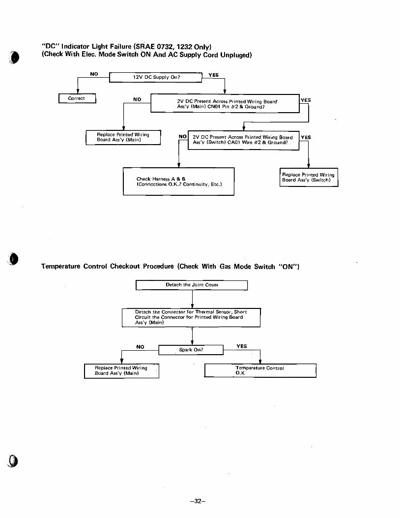
"DC" Indicator Light Failure (SRAE 0732,1232 Only) (Check With Elec. Mode Switch ON And AC Supply Cord Unpluged) a
Board Ass'y (Main) Ass'v (Switch) CAOl Wire #2 & Ground?
NO
1 12V DC Supply On? YES
Check Harness A & B (Connections O.K.? Continuity, Etc.)
Correct
Replace Printed Wiring Board Ass'y (Switch)
NO
, . ' Temperature Control Checkout Procedure (Check With Gas Mode Switch "ON")
I Detach the Joint Cover
-
Circuit the Connector for Printed Wiring Board Ass'y (Main)
NO
Replace Printed Wiring Board Ass'y (Main)
2V DC Present Across Printed Wiring Board Ass'y (Main) CNOl Pin #2 & Ground?
- YES
EAD LOCATION BRACKET
BURNER HEAD IGNITION PLUG
SPARK GAP
\
Fig. 17
I THERMOCOUPLE THERMOCOUPLE GAP
1)- 5/32" - 7/32" BURNER
I
HEAD

34. Changing Printed .Wiring Board Ass'y (Switch) and Buzzer
a) After removing the screws which hold CONTROL d) After removing the screws which hold Printed Wiring
CASE, and COIVTROL CASE CAP LEFTIRIGHT. Board Ass'y on WIRING BOARD MOUNTING Then remove CONTROL CASE. BRACKET, remove Printed Wiring Board Ass'y.
b) Remove CONNECTOR of PRINTED WIRING e) After removing the screws which hold BUZZER BOARD ASS'Y (Switch). ASS'Y, remove BUZZER ASS'Y.
C) Remove CONNECTOR of BUZZER ASS'Y. f ) Install new parts in reverse order of removal.
OL CASE CAP LEFT
BUZZER ASS'Y
CONTROL CASE
Fig. 18

35. Changing Printed Wiring Board Ass'y (Main)
a) After removing the screws which hold FLAME BLOW-OUT COVER, remove FLAME BLOW-OUT COVER. Remove the screws of BURNER BRACKET. (See Fig, 11 -1, 1 1-2)
b) After removing the screws which hold CASE WIRE SPLICER, remove CASE WIRE SPLICER. Remove COUPLER and DEPRESSING TERMINAL. Remove NYLON CLIP which holds LEAD and remove the screws of POWER CORD.
c) After taking off the tabs of GENERATOR COVER, remove SHUTTER. After removing HEATER SUPPORT, remove HEAT- ER by pulling upward.
Control Box Rear Ass'v Flame Blow Out Cover
Fig. 19
d) Remove the screws (x4) which hold CONTROL BOX a REAR ASS'Y. Remove CONTROL BOX REAR ASS'Y by pulling backward. After removing the screws (x4) which hold CON- TROL BOX CAP, remove CONTROL BOX CAP.
f ) Remove all COUPLERS connected to Printed Wiring Board Ass'y (Main). After removing the screws (x5) which hold Printed Wiring Board Ass'y (Main), pull out Printed Wiring Board Ass'y (Main.) Install new Printed Wiring Board Ass'y (Main) in reverse order of removal.
Fuse
Main P.W.B. ASS'V
Fig. 20
36. Changing of Fuse
After carrying out the process (a-d; Para 35), remove FUSE and replace. (See Fig. 19 - 20)

37. Changing Printed- Wiring Board Ass'y (Thermocouple)
a After carrying out the process (a - d; Para. 351, remove COUPLERS from Printed Wiring Board Ass'y (Therrno- couple) and THERMOSENSOR LEAD. Remove the screws (x4) of Printed Wiring Board Ass'y (Thermocouple). Install new BOARD in reverse order of removal. (See Fig. 20)
38- Changing Transformer
After carrying out the process (a - d; Para. 35), remove COUPLERS (LEADS: white x 2, red x 2) connected to Printed Wiring Board Ass'y (Main). Remove the screws of TRANSFORMER and change TRANSFORMER. Install new TRANSFORMER in reverse order of removal. (See Fig. 20)
39- Changing Relay (only for SRAE 0732, 1232)
After carrying out the process (a - d; Para. 35), remove the screws which hold LEADS (red, gray) to RELAY. Then remove the COUPLER (LEAD: BROWN).
.) Remove the screws of RELAY and change RELAY. Install new RELAY in reverse order of removal. (See Fig. 20.)
40. Changing Ignition Plug
a) Carry out process (a - d; Para. 35). I I b) Remove IGNITION BRACKET. Then pull off the
coupler connected to Printed Wiring Board Ass'y (Main) and change IGNITION PLUG. Replace the parts in reverse order of removal. 'P
I Fig. 21 I
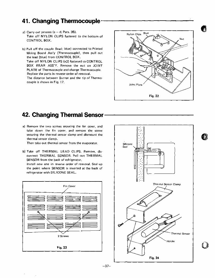
41. Changing Thermocouple
a) Carry out process (a - d; Para. 35). Take off NYLON CLIPS fastened to the bottom of CONTROL BOX.
b) Pull off the couple (lead: blue) connected to Printed Wiring Board Ass'y (Thermocouple), then pull out the lead (blue) from CONTROL BOX. Take off NYLON CLIPS (x2) fastened to CONTROL BOX REAR ASS'Y. Remove the nut on JOINT PLATE of Thermocouple and change Thermocouple. Replace the parts in reverse order of removal. The distance between Burner and the tip of Thermo- couple is shown in Fig. 17.
42. Changing Thermal Sensor
a) Remove the two screws securing the fin cover, and take down the fin cover, and remove the screw securing the thermal sensor clamp and dismount the thermal sensor clamp. Then take out thermal sensor from the evaporator.
b) Take off THERMAL LEAD CLIPS. Remove, dis- connect THERMAL SENSOR. Pull .out THERMAL SENSOR from the back of refrigerator. Install new one in reverse order of removal. Seal up the point where SENSOR i s inserted at the back of refrigerator with SILICONE SEAL.
Fin Cover -- I I- 1- -.-- -I-- ----
2 Screws
Fig. 23
Thermal Sensor Clamp
Thermal Sensor
43. Changing Heater.
SRAE 0732,1232 Carry out process (a - d; Para. 35). Detach NYLON CLIPS fastened to CONTROL BOX, and disconnect the JOINT WIRE connected to 3 brown leads and the one connected to red lead. Disconnect gray lead connected to DC RELAY. Take off the coupler (boldlwhite) connected to Printed Wiring Board Ass'y (Main). Disconnect leads (white, brown, gray; yellow) from CONTROL BOX. After changing HEATER, re- place these parts in reverse order of removal.
SRAE 0722,1222 Carry out process (a. c. d; Para. 35). Detach LEAD STOPPER, NYLON CLIPS and POWER CORD STOPPER. Remove CONTROL BOX from the back of refrigerator and then remove the LID of CONTROL BOX. Detach NYLON CLIP fastened to the bottom of CON- TROL BOX. Disconnect the coupler of HEATER CORD (Black x 2). then change. Replace the parts in reverse order of removal.
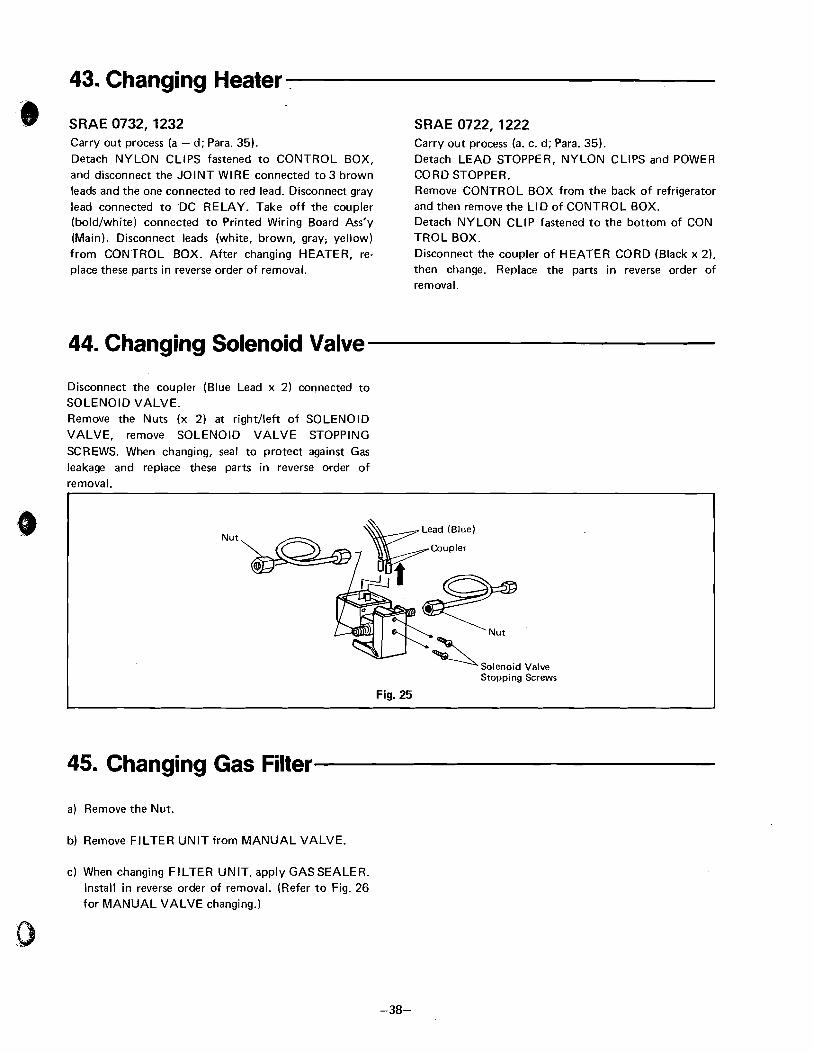
44. Changing Solenoid Valve
Disconnect the coupler (Blue Lead x 2) connected to SOLENOID VALVE. Remove the Nuts (x 2) at rightheft of SOLENOID VALVE, remove SOLENOID VALVE STOPPING SCREWS. When changing, seal to protect against Gas leakage and replace these parts in reverse order of removal.
Nut
Solenoid Valve Stopping Screws
Fig. 25
45. Changing Gas Filter
a) Remove the Nut.
b) Remove FILTER UNIT from MANUAL VALVE.
C) When changing FILTER UNIT. apply GAS SEALER. Install in reverse order of removal. (Refer to Fig. 26 for MANUAL VALVE changing.)
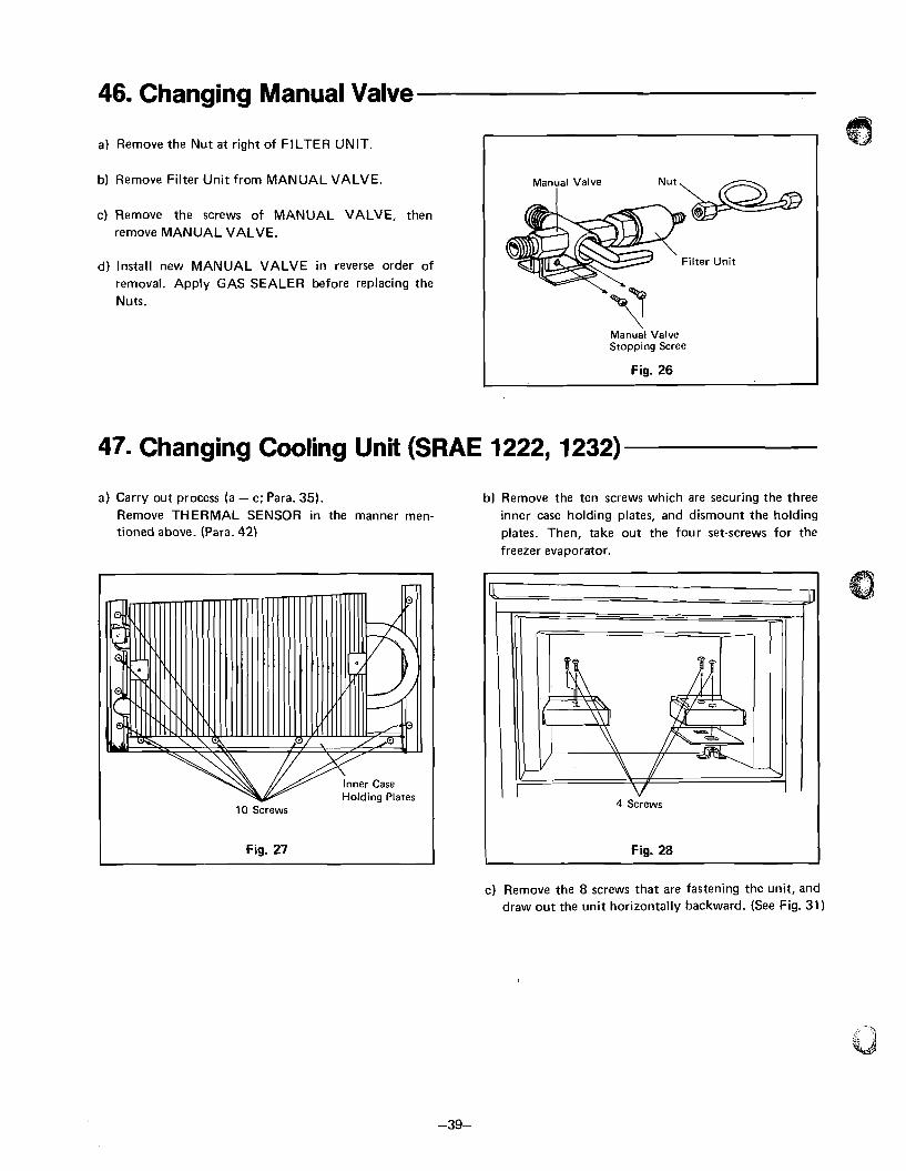
46. Changing Manual Valve
a) Remove the Nut a t right of FILTER UNIT
b) Remove Filter Unit from MANUAL VALVE.
c) Remove the screws of MANUAL VALVE, then I
remove MANUAL VALVE.
d) Install new MANUAL VALVE in reverse order of removal. Apply GAS SEALER before replacing the Nuts.
Manual Valve Stopping Scree
Fig. 26
47. Changing Cooling Unit (SRAE 1222, 1232)
a) Carry out process (a - c; Para. 35). b) Remove the ten screws which are securing the three Remove THERMAL SENSOR in the manner men- inner case holding plates, and dismount the holding tioned above. (Para. 42) plates. Then, take out the four set-screws for the
freezer evaporator.
c) Remove the 8 screws that are fastening the unit, and draw out the unit horizontally backward. (See Fig. 31)
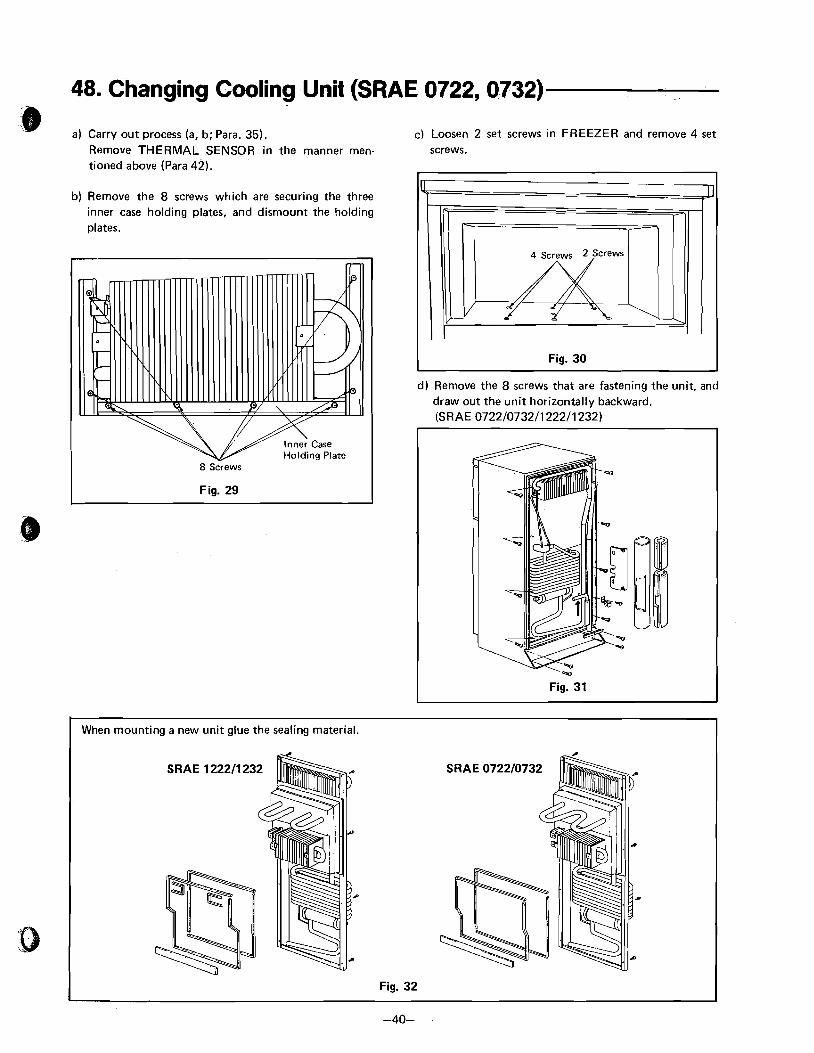
48. Changing Cooling Unit (SRAE 0722, 0732)
a a) Carry out process (a, b; Para. 35). C) Loosen 2 set screws in FREEZER and remove 4 set
Remove THERMAL SENSOR in the manner men- screws. tioned above (Para 42).
b) Remove the 8 screws which are securing the three inner case holding plates, and dismount the holding plates.
8 Screws
d) Remove the 8 screws that are fastening the unit, and draw out the unit horizontally backward. (SRAE 0722/0732/1222/1232)
Fig. 31
When mounting a new unit glue the sealing material.
SRAE 122211 232 S R A E 072210732
Fig. 32
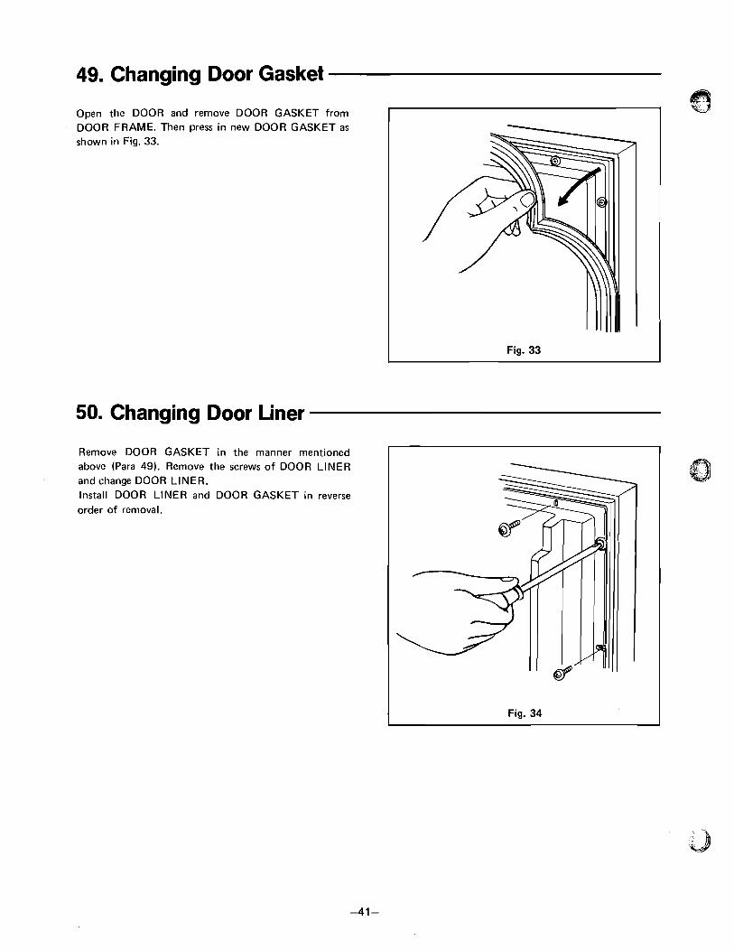
49. Changing Door Gasket
Open the DOOR and remove DOOR GASKET from 6
DOOR FRAME. Then press in new DOOR GASKET as shown in Fig. 33.
Fig. 33
50. Changing Door Liner
Remove DOOR GASKET in the manner mentioned above (Para 49). Remove the screws of DOOR LINER and change DOOR LINER. Install DOOR LINER and DOOR GASKET in reverse order of removal.
Fig. 34
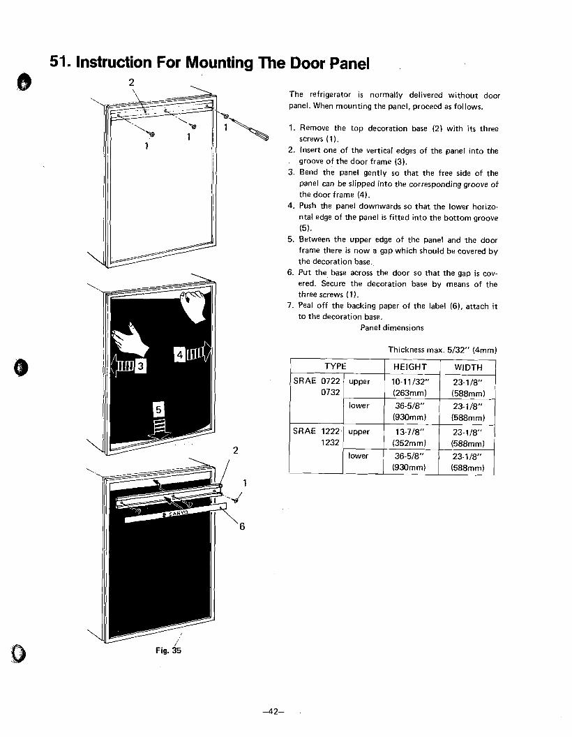
51. Instruction For Mounting The Door Panel
The refrigerator i s normally delivered without door panel. When mounting the panel, proceed as follows.
1. Remove the top decoration base (2) with i t s three screws (1 ).
4
2. Insert one of the vertical edges of the panel into the groove of the door frame (3).
3. Bend the panel gently so that the free side of the panel can be slipped into the corresponding groove of the door frame (4).
4. Push the panel downwards so that the lower horizo- ntal edge of the panel is fitted into the bottom groove
(5). 5. Between the upper edge of the panel and the door
frame there is now a gap which should be covered by the decoration base.
6. Put the base across the door so that the gap i s cov- ered. Secure the decoration base by means of the three screws (1 ).
7. Peal off the backing paper of the label (61, attach it to the decoration base.
Panel dimensions
Thickness max. 5/32" (4mm)
Fig. 35
TYPE HEIGHT
10-11132" (263mm)
36-5/8" (930mm)
13-718" (352mm)
36-518''
SRAE 0722 0732
SRAE 1222 1232
WIDTH
23- 118" (588rnm)
23-1/8" (588mm)
23-118" (588mm j
23- 1 18"
upper
lower
upper
lower ,
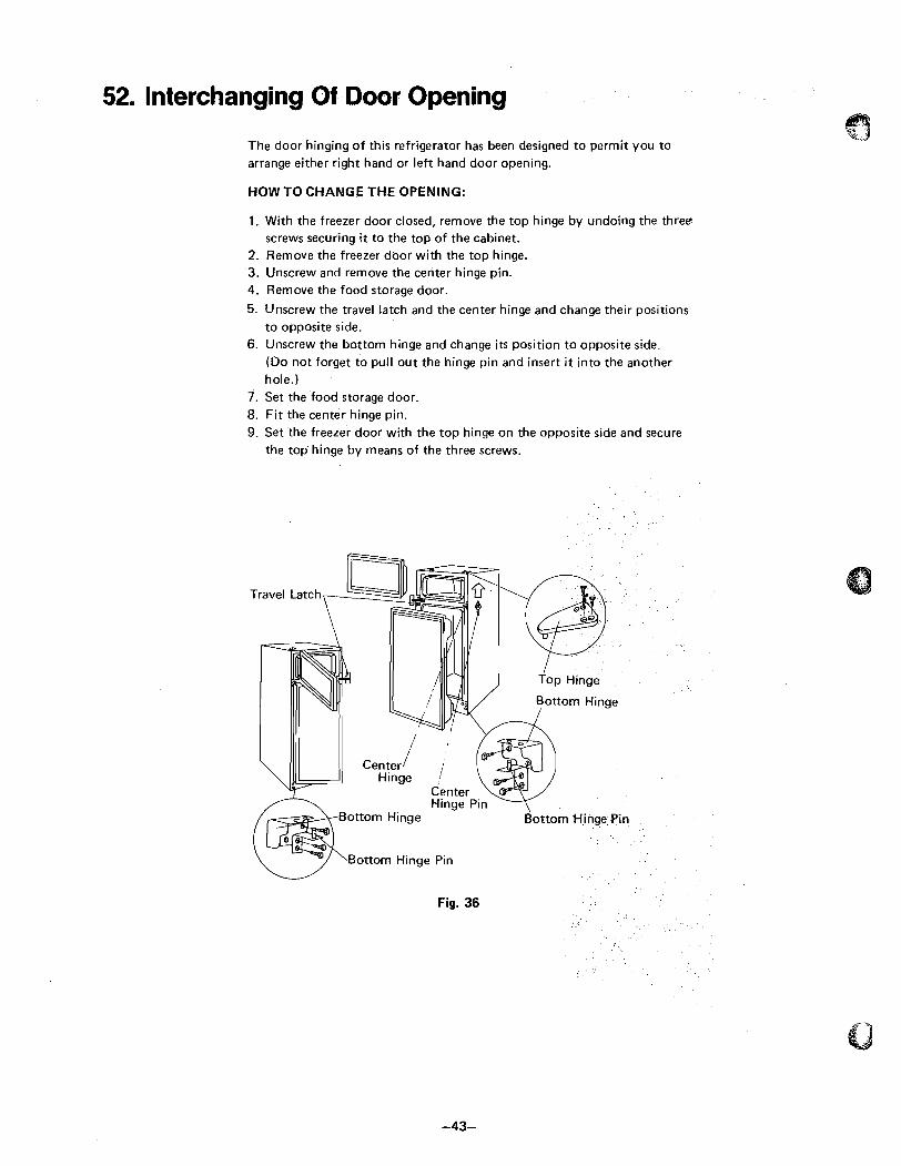
52. Interchanging Of Door Opening
The door hinging of this refrigerator has been designed to permit you to arrange either right hand or left hand door opening.
HOW TO CHANGE THE OPENING:
1. With the freezer door closed, remove the top hinge by undoing the three screws securing it to the top of the cabinet.
2. Remove the freezer door with the top hinge. 3. Unscrew and remove the center hinge pin. 4. Remove the food storage door.
5. Unscrew the travel latch and the center hinge and change their positions to opposite side.
6. Unscrew the bottom hinge and change i t s position to opposite side. (Do not forget to pull out the hinge pin and insert i t into the another hole.)
7. Set the food storage door. 8. Fit the center hinge pin. 9. Set the freezer door with the top hinge on the opposite side and secure
the top hinge by means of the three screws.
Bottom Hinge
Bottom Hinge Pin
Fig. 36

53. Changing Cabinet Frame Ass'y ,;a
a) Following 1 - 6 of Changing Door Openning, remove FREEZER FOOD STORAGE DOOR, TOP HINGE, CENTER HINGE, CENTER HlNGE PIN, BOTTOM HINGE and BOTTOM HINGE PIN. (Refer to Fig. 36)
b) Following Para 34 (CHANGING Printed Wiring Board Ass'y (Switch) AND BUZZER A - B), remove Printed Wiring Board Ass'y (Switch) and Wl RING BOARD MOUNTING BRACKET. (Refer to Fig. 18)
c) Remove PLATE MTG. UNDER LEFT AND RIGHT, LEAD PROTECTOR and SUPPORT SWITCH Printed Wiring Board Ass'y (Refer to Fig. 18).
d) Remove LEAD COVER and GROMMET.
e) Remove NUT DOOR SWITCH and SHIM from
CABINET FRAME BOTTOM.
f ) Remove CABINET PACKING Ass'y after removing the screws of CABINET FRAME Ass'y.
g) Paste FRAME SEAL A. B, CABINET PACKING SEAL and CABINET PACKING SEAL BOTTOM, and CABINET PACKING SEAL TOP onto new @ CABINET Frame Ass'y.
h) Install CABINET Frame Ass'y and other parts in reverse order of removal, and finally, paste CABINET PACKING TOP SEAL. Then apply SILICONE - SEALING all around the contact points of F - BREAKER located at the front of CABINET Frame Ass'y FREEZER. Also apply SILICONE - SEALING to Cabinet Frame Ass'y Bottom.