Classic Update Series - American Autowire 510368 IN 7.0.pdf · Install the Dimmer, Headlight, ......
14
Page 1 STEP 1: DISCONNECT YOUR BATTERY: Disconnect the battery before installing the wiring kit to prevent any accidental shorting caused by loose bare wire ends. STEP 2: START INSTALLING KIT (see page 3): This kit is broken down into individual steps that are identified by a letter printed on the instruction sheets visible through each bag. These letters are the order of operation for installing your kit. Start with bag letter G, then H, etc. The order of installation is shown below. Use this main instruction sheet, 92970307, to complete the installation process. H - 510370 Gauge Cluster Kit G - 510369 Dash Harness Kit M - 510371 Rear Body Kit STEP 3: RECONNECT YOUR BATTERY: When you have completed the installation and are ready to reconnect the battery, make sure that the following electrical system grounds are in place: A. Battery is grounded to the ENGINE BLOCK. B. Battery is grounded to the frame. C. Engine block is grounded to the frame. D. Body is grounded to the frame. STEP 4: CHECK ALL ELECTRICAL FUNCTIONS: Any non-functioning items should be checked for proper installation. Any problems with your wiring and electrical circuit functions should be addressed to American Autowire Systems, Inc. as soon as possible to avoid any warranty problems. If you have any questions concerning this or any of our products, please feel free to call us at 1-856-933-0801. AMERICAN AUTOWIRE MAKES IT EASY !! Classic Update Series 67-72 Ford Truck We carry many accessories for your 67-72 Ford Truck INSTALLATION INSTRUCTIONS end view of terminal proper crimp of terminal wire core 510368 Classic Update Series START HERE ! PLEASE READ THIS BEFORE STARTING INSTALLATION ! © COPYRIGHT 2004 American Autowire / Factory-Fit Used with express permission of American Autowire / Factory-Fit AS THIS HARNESS IS DESIGNED FOR USE IN A MODIFIED TRUCK REQUIRING A HIGHER RATE OF CHARGE, IT DOES NOT SUPPORT THE USE OF A STOCK (ORIGINAL) ALTERNATOR. IT IS DESIGNED FOR USE WITH AN INTERNALLY REGULATED GM “SI” STYLE OR SINGLE WIRE STYLE ALTERNATOR. ADAPTERS (WHICH ARE NOT INCLUDED WITH THIS KIT) THAT ARE AVAILABLE FROM SEVERAL SOURCES WILL BE NECESSARY TO USE ANY ALTERNATOR OTHER THAN A GM “SI” STYLE OR SINGLE WIRE STYLE UNIT. www.americanautowire.com 856-933-0801 This wiring kit is designed for ease of installation. Please read the guidelines below, BEFORE STARTING your installation to guarantee a successful job. Use an appropriate crimping tool which folds the wings of the open barrell terminals down into the wire as shown below. ALL TERMINALS THAT YOU INSTALL SHOULD BE PROPERLY SOLDERED. Our factory crimped terminations are installed by GM approved five ton presses, and soldering these terminations is not necessary. AAW offers a great terminal crimping video entitled “Proper Crimping Video”. It can be viewed by visting YouTube. Type the following address into your web browser to go directly to the video: www.youtube.com/watch?v=8u_EkMsioMy. 1967-72 Ford Truck PLEASE READ THESE HELPFUL INSTALLATION TIPS BEFORE GOING ANY FURTHER! Prior to installing the dash/main harness in your vehicle, plug all of the fuses, flashers, (see a detailed photograph on page 13 of this instruction set) and horn relay into the harness. Install the Dimmer, Headlight, Ignition and Wiper switches into their respective connectors on the harness assembly as well. These are all much easier to install onto the harness without the harness being installed in the vehicle. Once the switches and such have all been installed onto the harness, please use care when routing the assembly thru the vehicle as to not damage any of the switches by banging them into any metal supports. See the Fuse Panel Mounting Sheet 92970338, for installation and location of the Fuse Block. p/n 500918 Ford Duraspark Ignition Harness p/n 500802 GM “SI” series to Ford “3G” int. regulated alternator 92970307 Rev. 7.0 7/20/2017 p/n 510586 OEM large terminal crimping tool (12-8 gauge) p/n 510585 OEM small terminal crimping tool (18-14 gauge)
Transcript of Classic Update Series - American Autowire 510368 IN 7.0.pdf · Install the Dimmer, Headlight, ......

Page 1
STEP 1: DISCONNECT YOUR BATTERY:Disconnect the battery before installing the wiring kit to prevent any accidental shorting caused by loose bare wire ends.
STEP 2: START INSTALLING KIT (see page 3): This kit is broken down into individual steps that are identified by a letter printed on the instruction sheets visible through each bag. These letters are the order of operation for installing your kit. Start with bag letter G, then H, etc. The order ofinstallation is shown below. Use this main instruction sheet, 92970307, to complete the installation process.
H - 510370 Gauge Cluster KitG - 510369 Dash Harness Kit
M - 510371 Rear Body Kit
STEP 3: RECONNECT YOUR BATTERY:When you have completed the installation and are ready to reconnect the battery, make sure that the following electrical system grounds are in place:
A. Battery is grounded to the ENGINE BLOCK.B. Battery is grounded to the frame.C. Engine block is grounded to the frame.D. Body is grounded to the frame.
STEP 4: CHECK ALL ELECTRICAL FUNCTIONS:Any non-functioning items should be checked for proper installation. Any problems with your wiring and electrical circuit functions should be addressed to American Autowire Systems, Inc. as soon as possible to avoid any warranty problems.
If you have any questions concerning this or any of our products, please feel free to call us at 1-856-933-0801.
AMERICAN AUTOWIRE MAKES IT EASY !!
Classic Update Series67-72 Ford Truck
We carry many accessories for your 67-72 Ford Truck
INSTALLATION INSTRUCTIONS
end view of terminal proper crimp of terminal
wire core
510368
Classic Update Series
START HERE !PLEASE READ THIS BEFORE STARTING INSTALLATION !
© COPYRIGHT 2004 American Autowire / Factory-Fit Used with express permission of American Autowire / Factory-Fit
AS THIS HARNESS IS DESIGNED FOR USE IN A MODIFIED TRUCK REQUIRING A HIGHER RATE OF CHARGE, IT DOES NOT SUPPORT THE USE OF A STOCK (ORIGINAL) ALTERNATOR. IT IS DESIGNED FOR USE WITH AN INTERNALLY REGULATED GM “SI” STYLE OR SINGLE WIRE STYLE ALTERNATOR. ADAPTERS (WHICH ARE NOT INCLUDED WITH THIS KIT) THAT ARE AVAILABLE FROM SEVERAL
SOURCES WILL BE NECESSARY TO USE ANY ALTERNATOR OTHER THAN A GM “SI” STYLE OR SINGLE WIRE STYLE UNIT.
www.americanautowire.com 856-933-0801
This wiring kit is designed for ease of installation. Please read the guidelines below, BEFORE STARTING your installation to guarantee a successful job. Use an appropriate crimping tool which folds the wings of the open barrell terminals down into the wire as shown below. ALL TERMINALS THAT YOU INSTALL SHOULD BE PROPERLY SOLDERED. Our factory crimped terminations are installed by GM approved five ton presses, and soldering these terminations is not necessary. AAW offers a great terminal crimping video entitled “Proper Crimping Video”. It can be viewed by visting YouTube. Type the following address into your web browser to go directly to the video: www.youtube.com/watch?v=8u_EkMsioMy.
1967-72 Ford Truck
PLEASE READ THESE HELPFUL INSTALLATION TIPS BEFORE GOING ANY FURTHER!Prior to installing the dash/main harness in your vehicle, plug all of the fuses, flashers, (see a detailed photograph on page 13 of this
instruction set) and horn relay into the harness. Install the Dimmer, Headlight, Ignition and Wiper switches into their respective connectors on the harness assembly as well. These are all much easier to install onto the harness without the harness being installed in the vehicle. Once the switches and such have all been installed onto the harness, please use care when routing the assembly thru
the vehicle as to not damage any of the switches by banging them into any metal supports. See the Fuse Panel Mounting Sheet 92970338, for installation and location of the Fuse Block.
p/n 500918Ford Duraspark Ignition Harness
p/n 500802GM “SI” series to Ford “3G” int.
regulated alternator
92970307 Rev. 7.0 7/20/2017
p/n 510586OEM large terminal crimping
tool (12-8 gauge)
p/n 510585OEM small terminal crimping
tool (18-14 gauge)
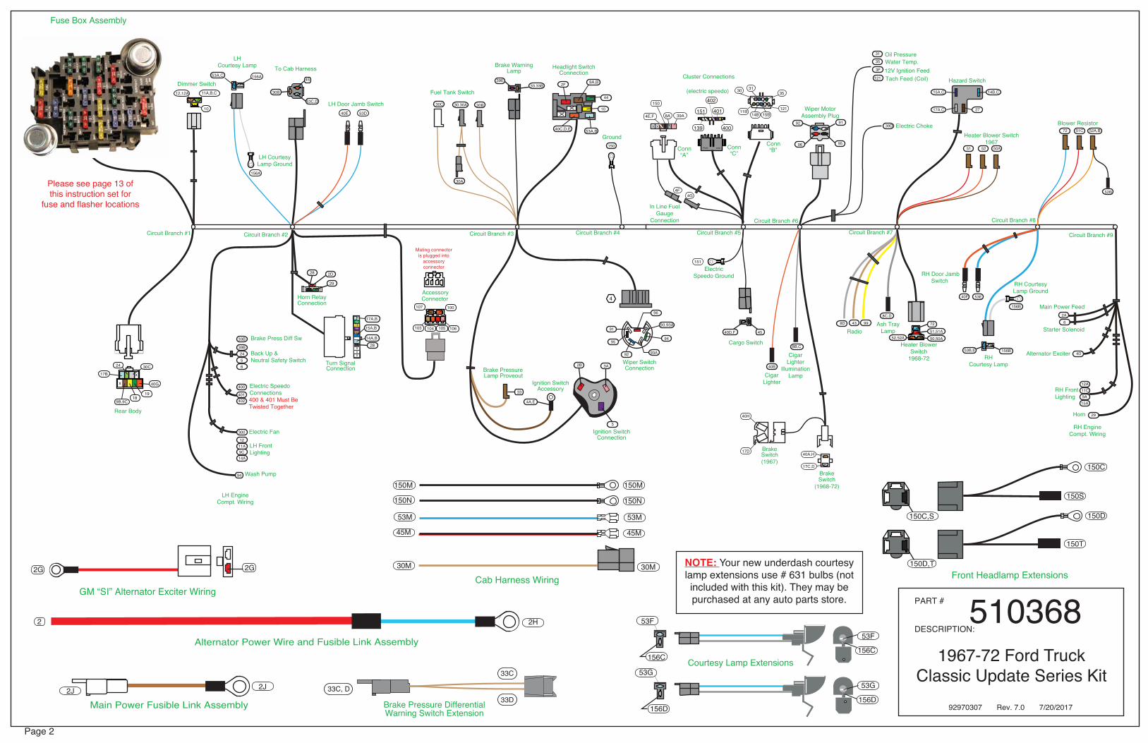
Page 2
PART #
DESCRIPTION:510368
Main Power Fusible Link Assembly
Alternator Power Wire and Fusible Link Assembly 156C
156C
156D
150D,T
150C,S
156D
53F
53G
2 2H
2J 2J
Front Headlamp Extensions
53F
53G
150S
150T
1967-72 Ford Truck Classic Update Series Kit
PACK CON
139
151
402
401
400
Dimmer Switch
Fuse Box Assembly
To Cab Harness
4
11A,B,C12,12A
10
30C
40G
24
17B
1918
Rear Body
156A
156A
Accessory
103 104 105 106
100107
Headlight SwitchConnection
Horn RelayConnection
Wiper SwitchConnection
Conn“A”
Conn“C”
Conn“B”
(electric speedo)
Cluster Connections
39A
151
15B14B11B 121
3130 35
4E,F
4F
150
Circuit Branch #1
LH Door Jamb Switch
39E
150
45
53C,D
9B,9C
2D
29
28
53A,C
14A,B
15A,B
17A,B
X
Turn SignalConnection
1918
Brake Press Diff Sw
Electric SpeedoConnections400 & 401 Must BeTwisted Together
Back Up &Neutral Safety Switch
Wash Pump
LH FrontLighting
LH EngineCompt. Wiring
33B
39B2456
300
1211A9C14A
400
401402
44
XX
96
91
9495
92
10
93A
53A,B
93,93A
9A,B
40C,D,E
28
27
8A
xx
x
LHCourtesy Lamp
LH Courtesy Lamp Ground
Electric Fan
16
Electric Speedo Ground
Ground
In Line FuelGauge
Connection
Cargo Switch
40A,H
17C,D
Ignition SwitchConnection
Ignition SwitchAccessory
Heater Blower Switch1967
RHCourtesy Lamp
Starter Solenoid
Main Power Feed
Alternator Exciter
Circuit Branch #9Circuit Branch #5
Blower Resistor
Circuit Branch #4Circuit Branch #2 Circuit Branch #3
Radio
CigarLighter
Ash TrayLamp
Horn
RH FrontLighting
4D
29
12A11C9A15A
62A
2B 3A
15A,C
51 52 50A
99438C,D
40B
5
4A,E
4540D,F
33
156B
156B53B,E
Wiper MotorAssembly Plug
BrakeSwitch
(1968-72)
9192
96 95
RH Courtesy Lamp Ground
RH EngineCompt. Wiring
Mating connector is plugged into
accessory connector
Please see page 13 of this instruction set for
fuse and flasher locations
2G2G
GM “SI” Alternator Exciter Wiring
Connector
Brake PressureLamp Proveout
40E 53D
44
2F
30B30,30A30C
30A
4G
Brake WarningLamp
Fuel Tank Switch
CigarLighter
IlluminationLamp
8B,C
40H
17D BrakeSwitch(1967)
Oil PressureWater Temp.12V Ignition FeedTach Feed (Coil)
Electric Choke
31
35
3F
121
39D
17A,C
14B,C
27
Circuit Branch #7
Circuit Branch #8
Hazard Switch
72 51C 52A,B
52B
8D
Heater BlowerSwitch
1968-72
RH Door JambSwitch
40F 53E
72
51,51A
50,50A52,52A
Circuit Branch #6
30B
x
94
33,33B
Cab Harness Wiring
150C
150D
150M
150N
53M
45M
30M
150M
150N
53M
45M
30M
XX
Courtesy Lamp Extensions
NOTE: Your new underdash courtesy lamp extensions use # 631 bulbs (not included with this kit). They may be purchased at any auto parts store.
92970307 Rev. 7.0 7/20/2017Brake Pressure DifferentialWarning Switch Extension
33C, D
33C
33D

Page 3
www.americanautowire.com 856-933-0801
Dash/Main Harness Installation Instructions
The Main Dash Harness 510369 is designed to be mounted in the same location as the original Instrument Panel Harness. Mount the Fuse Block first using the two#10 x 3” screws found in kit 510369. Mount the Fuse Block (see the Fuse Panel Mounting Sheet - 92970388). You will reuse the two original wraparound clips that are attached to the steering column brace to hold the new Dash Harness in place as well as the original clip near the top center of the firewall. Follow these instructions as well as the detailed drawings on pages 11 and 12. After mounting the Fuse Block, install the two 1-1/4” grommets G from kit 510376 into the outboard firewall holes, and the 1” grommet R near the center of the firewall. These are the same wiring pass through holes as used originally.
Circuit Branch 1 - Underdash ConnectionsWire # Wire Color Printing Procedure
Dimmer Switch Plug this connector onto the Dimmer Switch 500042 and then attach the Dimmer Switch to the floor pan.
10 Yellow Dimmer SW Feed Feed from the Headlight Switch.
11A Light Green Headlight Hi-Beam Feed to LH Headlight High Beam.
11B Light Green Hi-Beam Indicator Light Feed to the Hi Beam Indicator Light.
11C Light Green Headlight Hi-Beam Feed to the RH Headlight-High Beam.
12,12A Tan Headlight-Low Beam Feed to LH and RH Headlights-Low Beam.
Rear Body Connection This connector will plug into the Rear Body Kit, 510371. Specific connections are addressed in that kit. The Rear Body Harness will pass out to the engine compartment through the LH driver’s side firewall grommet G (included in kit 510376) shown on page 12, Figure C.
9B Brown Rear Running Lights Feed for the Rear Park, Side Marker and License Lamps. 9C Brown Park Lights Feed for the Front Park Lights.
17B Lt. Blue Third Brake Light Feed for an aftermarket Third Brake Light.
18 Yellow Left Rear Turn Feed to the Left Rear Stop and Turn Lamp.
19 Dk. Green Right Rear Turn Feed to the Right Rear Stop and turn Lamp.
24 Lt. Green Back Up Lt Sw Feed to the Back-up Lamp Switch.
30C White Gas Gauge AUX Tank Auxiliary Fuel Tank Sender.
40G Orange 12v Battery Fused 12v battery feed for aftermarket LED Rear Lights.
Circuit Branch 2 - Under Hood Connections LH Engine Compartment (Drivers Side)
Brake Pressure Differentail Switch (NOTE:) We have provided you with the connection to the original Ford brake warning switch in the form of a wire extension assembly (wires 33C, D on page 2 of this instruction sheet). You will plug this extension onto wire 33B, below.
33B Tan Brake Switch Route this wire to the brake warning switch area near the master cylinder, cut to length, install terminal B, plug into connector E as shown on page 12, figure C, then plug this wire into wire extension assembly 33C, D (from page 2 of this instruction sheet) to complete your brake warning circuit.
The Back-up and Neutral Safety Switches Route the circuits to the Back-up Lamp Switch and to the Neutral Safety Switch and connect. For 4-speed M/T applica-tions, the Back-up Switch is located at the top rear of the transmission. for 3-speed M/T applications, the Back-up Switch is located on the steering column in the engine compartment. For Automatic Transmission applications, the Neutral Safety/Back-up Switch is located near the Steering Column or on the transmission depending on transmission. If you have a manual transmission, connect the 5 and 6 wires together to complete the starter circuit or your vehicle will not crank. A typical aftermarket connection for the Neutral Safety/Back-up Switch can be found on page 12, Figure E.
5 Purple Neutral Safety Switch Start feed from the Ignition Switch to the Neutral Safety Switch.
6 Purple Starter Solenoid Start circuit from the Neutral Safety Switch to the Starter Solenoid.
24 Light Green Back UP LT SW Feed from the Back-up Lamp Switch to the Back-up Lamps.
39B Pink 12V Ignition 12V feed to the Back-up Lamp Switch.
Continued on page 4
PART #
DESCRIPTION:510368
1967-72 Ford Truck Classic Update Series Kit
Fuse Box Assembly
40G
24
17B
1918
Rear Body9B,9C
x
Please see page 13 of this instruction set for
fuse and flasher locations
x
30C
Brake Press Diff Sw
Back Up &Neutral Safety Switch
LH EngineCompt. Wiring
33B
39B2456
Circuit Branch #1 Circuit Branch #2
Dimmer Switch11A,B,C12,12A
10
92970307 Rev. 7.0 7/20/2017
Page 4
Dash/Main Harness Installation Instructions
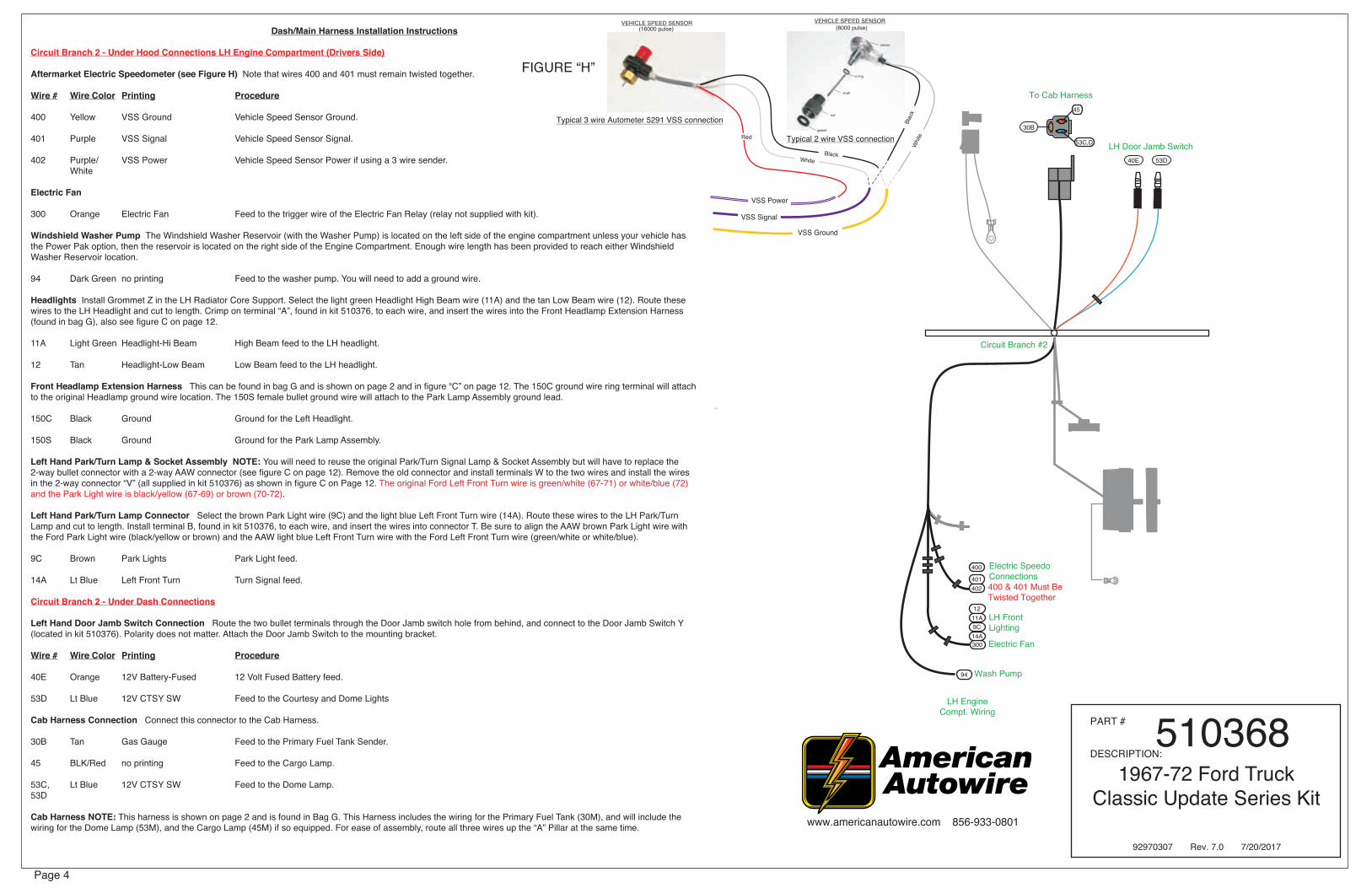
Circuit Branch 2 - Under Hood Connections LH Engine Compartment (Drivers Side)
Aftermarket Electric Speedometer (see Figure H) Note that wires 400 and 401 must remain twisted together.
Wire # Wire Color Printing Procedure
400 Yellow VSS Ground Vehicle Speed Sensor Ground.
401 Purple VSS Signal Vehicle Speed Sensor Signal.
402 Purple/ VSS Power Vehicle Speed Sensor Power if using a 3 wire sender. White
Electric Fan
300 Orange Electric Fan Feed to the trigger wire of the Electric Fan Relay (relay not supplied with kit).
Windshield Washer Pump The Windshield Washer Reservoir (with the Washer Pump) is located on the left side of the engine compartment unless your vehicle has the Power Pak option, then the reservoir is located on the right side of the Engine Compartment. Enough wire length has been provided to reach either Windshield Washer Reservoir location.
94 Dark Green no printing Feed to the washer pump. You will need to add a ground wire.
Headlights Install Grommet Z in the LH Radiator Core Support. Select the light green Headlight High Beam wire (11A) and the tan Low Beam wire (12). Route these wires to the LH Headlight and cut to length. Crimp on terminal “A”, found in kit 510376, to each wire, and insert the wires into the Front Headlamp Extension Harness (found in bag G), also see figure C on page 12.
11A Light Green Headlight-Hi Beam High Beam feed to the LH headlight.
12 Tan Headlight-Low Beam Low Beam feed to the LH headlight.
Front Headlamp Extension Harness This can be found in bag G and is shown on page 2 and in figure “C” on page 12. The 150C ground wire ring terminal will attach to the original Headlamp ground wire location. The 150S female bullet ground wire will attach to the Park Lamp Assembly ground lead.
150C Black Ground Ground for the Left Headlight.
150S Black Ground Ground for the Park Lamp Assembly.
Left Hand Park/Turn Lamp & Socket Assembly NOTE: You will need to reuse the original Park/Turn Signal Lamp & Socket Assembly but will have to replace the 2-way bullet connector with a 2-way AAW connector (see figure C on page 12). Remove the old connector and install terminals W to the two wires and install the wires in the 2-way connector “V” (all supplied in kit 510376) as shown in figure C on Page 12. The original Ford Left Front Turn wire is green/white (67-71) or white/blue (72) and the Park Light wire is black/yellow (67-69) or brown (70-72).
Left Hand Park/Turn Lamp Connector Select the brown Park Light wire (9C) and the light blue Left Front Turn wire (14A). Route these wires to the LH Park/Turn Lamp and cut to length. Install terminal B, found in kit 510376, to each wire, and insert the wires into connector T. Be sure to align the AAW brown Park Light wire with the Ford Park Light wire (black/yellow or brown) and the AAW light blue Left Front Turn wire with the Ford Left Front Turn wire (green/white or white/blue).
9C Brown Park Lights Park Light feed.
14A Lt Blue Left Front Turn Turn Signal feed.
Circuit Branch 2 - Under Dash Connections
Left Hand Door Jamb Switch Connection Route the two bullet terminals through the Door Jamb switch hole from behind, and connect to the Door Jamb Switch Y (located in kit 510376). Polarity does not matter. Attach the Door Jamb Switch to the mounting bracket.
Wire # Wire Color Printing Procedure
40E Orange 12V Battery-Fused 12 Volt Fused Battery feed.
53D Lt Blue 12V CTSY SW Feed to the Courtesy and Dome Lights
Cab Harness Connection Connect this connector to the Cab Harness.
30B Tan Gas Gauge Feed to the Primary Fuel Tank Sender.
45 BLK/Red no printing Feed to the Cargo Lamp.
53C, Lt Blue 12V CTSY SW Feed to the Dome Lamp.53D
Cab Harness NOTE: This harness is shown on page 2 and is found in Bag G. This Harness includes the wiring for the Primary Fuel Tank (30M), and will include the wiring for the Dome Lamp (53M), and the Cargo Lamp (45M) if so equipped. For ease of assembly, route all three wires up the “A” Pillar at the same time. www.americanautowire.com 856-933-0801
PART #
DESCRIPTION:510368
1967-72 Ford Truck Classic Update Series Kit
To Cab Harness
LH Door Jamb Switch
45
53C,D
X
1918
Electric SpeedoConnections400 & 401 Must BeTwisted Together
Wash Pump
LH FrontLighting
LH EngineCompt. Wiring
300
94
1211A9C14A
400
401402
27
Electric Fan
16
Circuit Branch #2
40E 53D
30B
4
Typical 2 wire VSS connectiongasket
nut
shaft
VEHICLE SPEED SENSOR(8000 pulse)
o-ring
sensor
Typical 3 wire Autometer 5291 VSS connection
VEHICLE SPEED SENSOR (16000 pulse)
Blac
kW
hite
Black
VSS Signal
VSS Ground
FIGURE “H”
White
Red
VSS Power
92970307 Rev. 7.0 7/20/2017

Page 5
Dash/Main Harness Installation Instructions ProcedureCircuit Branch 2 - Underdash ConnectionsFuel Tank Wiring If you have an In-Cab Fuel Tank, 30M will be routed up the “A” Pillar and back to the Fuel Tank. Cut to length, slide on sleeve J, install ring terminal M, and position the sleeve over the crimped wires. Attach the ring terminal M to the Fuel Tank Sender. Attach the ring terminal of Ground Wire 150M to ground at the original ground location and route the other end of 150M to the Fuel Tank sender. Install terminal F and plug into connector H. Attach to the fuel Tank sender ground. If you don’t have an In-Cab Fuel Tank, route 30M out through the firewall grommet G and back to the Fuel Tank alongside the Rear Body Wiring. Cut to length, crimp on terminal B, and add Connector E, then connect to the Fuel Tank Extension Harness (from Bag M - 510371 Rear Body Kit).
Wire # Wire Color Printing Procedure
30M Tan Gas Gauge Feed to the Primary Fuel Tank.
150M Black Ground Primary Fuel Tank Sender Ground.Dome Lamp Wiring If you have a Dome-Lamp, obtain circuit 53M from kit Bag G and plug into the 3-way Cab Harness (see page 2). Be sure to match the wire colors with the Dash Harness connector. Route the other end of 53M up the “A” Pillar and over to the Dome Lamp. Cut to length, slide on sleeve D, install terminal X, and position the sleeve over the crimped wires. Connect terminal X to the Dome Lamp pigtail.
53M Light Blue 12V CTSY SW Feed to the Dome Lamp.
Cargo Lamp Wiring If you have a Cargo Lamp, obtain circuit 45M from Bag G and plug into the 3-way Cab Harness (see page 2). Be sure to match the wire colors with the Dash Harness connector. Route the other end of 45M up the “A” Pillar and over to the Cargo Lamp. Cut to length, slide on sleeve D, install terminal X, and position the sleeve over the crimped wires. Connect terminal X to the 2-way molded connector at the Cargo Lamp pigtail. Attach the ring terminal of Ground wire 150N to a good ground location and route the other end of 150N to the Cargo Lamp.Cut to length, slide on sleeve J, install terminal U, and position the sleeve over the crimped wires. Connect terminal U to the 2-way molded connector at the Cargo Lamp pigtail. The Ford feed wire to the cargo lamp is black/red and the ground is black.
45M Black/Red no printing Feed to the Cargo Lamp.
150N Black Ground Cargo Lamp Ground.
Left Hand Courtesy Lamp Connector Plug in one Under Dash Courtesy Lamp Extension in bag G (as shown on page 2) to complete this circuit and attach to the lower Instrument Panel.
53A, Light Blue 12V CTSY SW Feed to the Left Hand Courtesy Lamp.53C
156A White CTSY Ground LH Courtesy Lamp ground. Attach this ring terminal to a good chassis ground.
Accessory Connector Use the provided 6-way empty connector, which is attached to the 6-way connector on the Dash Harness, and terminals B or C (see kit 510376) to add power leads (not provided) for the following systems:
Wire# Wire Color Printing Fuse block Rating Description
100 Orange no printing BAT3 20A Battery feed for Audio systems.103 Tan Fuel Pump not marked 20A Ignition feed for electric fuel pump or fuel flow valve.104 Orange Power Seats BAT2 30A Battery feed for Power Seats.105 Red Power Locks BAT1 20A Battery feed for Power Locks.106 Pink Power windows PWR WDO 30A Ignition feed for Power Windows.107 Brown no printing ACCY1 30A Accessory feed for Cruise Control or options.
Horn Relay Connector Plug the Horn relay (found in the 510353 Fuse kit) into this connector.
2D Red 12V Battery 12V Battery feed to the Horn Relay.
28 Black Horn Relay Ground Relay fround circuit (to Steering Column).
29 Dark Green Horn Feed to the Horn.
Turn Signal Switch Connector Plug into the Steering Column Turn Signal Switch Connector. If you are using a stock Ford Steering Column on your vehicle, refer to Diagram ‘A’ and “Table A” - AAW Turn Signal Switch wires to stock turn signal switch on page 10 for proper mating directions. This Dash Harness is designed to function with a GM style turn signal switch. Our connector mates to a 3 7/8 inch long plug used on 1969-74 GM, IDIDIT, and many other aftermarket steering columns. Starting from 1975 on up, the GM switch changed and began using a 4-1/4 inch connector. That connector is from the same family and uses the same terminals. By using the supplied mating connector (L) and terminals (M) located in the loose piece kit bag G, it is easy to adapt any steering column to this Dash Harness. The different functions of the wires are as follows:
14A, 14B Light Blue Left Front Turn Feed to LH Front Turn Signal Lamp and cluster Indicator Lamp.
15A,15B Dark Blue Right Front Turn Feed to RH Front Turn Signal Lamp and Cluster Indicator Lamp.
16 Purple Turn Switch Feed Turn Signal feed into Steering Column from the turn Signal Flasher.
17A Light Blue Third Brake Light 12V feed to Third Brake Light.
17B White Brake SW 12V input from Brake Switch to Turn Switch for Rear Brake Lights.
18 Yellow Left Rear Turn Feed to LH Rear Turn Signal Lamp.
19 Dark Green Right Rear Turn Feed to RH Rear Turn Signal Lamp.
28 Black Horn Relay Ground Steering Column Horn ground from Horn Relay. www.americanautowire.com 856-933-0801
PART #
DESCRIPTION:510368
1967-72 Ford Truck Classic Update Series Kit
Accessory
103 104 105 106
100107
Mating connector is plugged into
accessory connector
ConnectorHorn RelayConnection
2D
29
28
14A,B
15A,B
17A,B
X
Turn SignalConnection
1918
28
27
7.0
16
Circuit Branch #2
XX
33B
39B2456
156A
156A
45
53C,D53A,C
LHCourtesy Lamp
Connector
LH Courtesy Lamp Ground
30B
To Cab Harness
NOTE: The courtesy lamp extension from page 2, that plugs onto the
connector at branch 2 on this page, uses a # 631 bulb (not included with this kit). They may be purchased at
any auto parts store.
92970307 Rev. 7.0 7/20/2017

Page 6
Dash/Main Harness Installation InstructionsCircuit Branch 3 - Under Dash Connections
Headlight Switch Connector Plug this connector to Headlight Switch 510321. Wire # Wire Color Printing Procedure
2F Red 12V Battery Un-fused 12V Battery feed from the Fuse Block.
9A Brown Park Lights Feed to Front Park Lights.
9B Brown Rear Running Lights Feed to Rear Tail Lights, Rear Side Marker Lights and License Lamps.
10 Yellow Dimmer SW Feed Feed to Dimmer Switch for Headlights.
40C Orange 12V Battery-Fused Fused 12V battery feed from the Fuse Block.
40D Orange 12V Battery-Fused Feed to the Cargo Lamp Switch.
40E Orange 12V Battery-Fused Feed to LH Door Jamb Switch.
44 Dark Green no printing Feed to Fuse Block for Dash Lights.
53A,53B Light Blue 12V CTSY SW 12V Switched feed to Courtesy Lights and Dome Lamp.
Brake Warning Lamp The original Dash mounted Brake Warning Lamp uses a unique socket assembly that must be re-used. You will need to cut the purple (for 1967 it is green) and red with yellow stripe (for 1967 it is yellow) wires about 5 inches from the back of the original socket and install terminal B to each wire. Plug these wires into connector T so that the original red with a yellow stripe (or yellow) wire mates with the AAW pink “12V ignition” wire, and the original purple (or green) wire mates with the AAW tan “Brake Light/Switch” wire.
33,33B Tan Brake Light/Switch Ground for the Brake Warning Lamp.
39E Pink 12V Ignition 12V Ignition feed for the Brake Warning Lamp.
Fuel Tank Switch Connectors If your truck has dual fuel tanks, plug the three 1-way Fuel Tank Switch connectors onto your Fuel Tank Selector Switch, as shown in Figure F, then install the switch into the Dash. If your truck only has a single tank, plug the tan 30B wire with the black connector, into the mating black connector on the tan 30A wire. No other connections are necessary.
30 Tan Gas gauge Gas gauge feed to the Cluster connector.
30A Tan Gas Gauge Fuel Tank Selector Switch pigtail.
30B Tan Gas Gauge Feed to the Primary Fuel Tank Sender.
30C White Gas Gauge Aux Tank Feed to the Auxiliary Fuel Tank Sender.
Wiper Switch Connector Plug this connector onto the Wiper Switch 510322.
91 White no printing Switched 12V lead out for wiper low speed.
92 Dark Blue no printing Switched 12V lead out for wiper high speed.
93,93A White Wiper Feed 12V fused feed for Wiper Switch Assembly.
93A White Wiper Feed 12V fused feed for Washer Pump.
94 Dark Green no printing Switched 12V lead out for Washer Pump.
95 Black no printing Wiper Motor park.
96 Red no priting Wiper Motor low park.
Ignition Switch Connector Plug this connector to the Ignition Switch 510053.
2B Red 12V Battery 12V un-fused battery feed from the Fuse Block.
3A Pink Ignition Feed Ignition feed to the Fuse block.
5 Purple Neutral Safety Switch Start feed to the Neutral Safety Switch.
Ignition Switch Accessory Eyelet Attach this eyelet to the Ignition Switch after the Ignition Switch Connector is plugged in. Use the nut to securely fasten the eyelet to the Ignition Switch threaded stud.
4A Brown Ignition SW ACCY Accessory feed to the Fuse Block.
4E Brown/White no printing Accessory feed (resistance wire) to the Cluster.
Ignition Switch 1-way Connector Connect this to the Ignition Switch after the Ignition Switch Accessory Eyelet is attached. this connector plugs onto the blade terminal which is located on the side of the Ignition Switch. This wire provides the bulb check ground for the Brake Warning Lamp circuit when the Ignition Switch is in the “Start” position.
33 Tan Brake Light/switch Brake Warning Lamp bulb check during crank.
Circuit Branch 4 - Under dash ConnectionGround Lead Attach this wire to a good chassis ground. NOTE: DO NOT attach this eyelet with the 151 ground wire in Circuit Branch #5.
150 Black Ground Cluster ground www.americanautowire.com 856-933-0801
PART #
DESCRIPTION:510368
1967-72 Ford Truck Classic Update Series Kit
4
Headlight SwitchConnection
Wiper SwitchConnection
39E
150
33,33B
XX
96
91
9495
92
10
93A
53A,B
93,93A
9A,B
40C,D,E
Ground
Ignition SwitchConnection
Ignition SwitchAccessory
Circuit Branch #4Circuit Branch #3
2B 3A
5
4A,E
33
Brake PressureLamp Proveout
44
2F
30B30,30A30C
30A
Brake WarningLamp
Fuel Tank Switch
Figure “F”Dual fuel tank
switch connection
92970307 Rev. 7.0 7/20/2017

Page 7
Dash/Main Harness Installation InstructionsCircuit Branch 5 - Under Dash Connections
Aftermarket Electric speedometer Ground Attach this wire to a good chassis ground. NOTE: DO NOT attach this eyelet with the “150” ground eyelet in Circuit Branch #4.
Wire# Wire Color Printing Procedure
151 Black/White Speedo Ground Ground for an Aftermarket Electric Speedometer.
Instrument Cluster Connections These connections will plug into the cluster connection Kit 510370 (see Bag H). Instructions are included in that kit.
Cluster Connector “A”
4E Brown/White no printing Cluster feed (resistance wire - 8.5 ohms) for 1970-1972 vehicles.
4F Brown no printing Cluster 12V feed for 1967-1969 vechicles.
8A Gray Dash Lights Fused 12V from the Fuse Block for the Cluster Illumination Lights.
39A Pink 12V Ignition fused 12V for Oil Pressure Lamp or Aftermarket Gauges.
150 Black Ground Cluster ground.
Cluster Connector “A” Inline 12V Feed Connection NOTE: Connect the 1-way male and female black connectors for the 1967-1969 vehicles. Do no connect if you have a 1970-1972 truck.
4F Brown no printing Cluster 12V feed for 1967-1969 vehicles.
4G Brown no printing Cluster 12V feed for 1967-1969 vechicles.
Cluster Connector “B”
11B Light Green Hi Beam Indicator Light Feed to High Beam Indicator Light.
14C Light Blue Left Dash IND Feed to Left Turn Signal Indicator Light.
15B Dark Blue Right Dash IND Feed to Right Turn Signal Indicator Light.
30 Tan Gas Gauge Fuel Sender signal from the Fuel Tank Sending Unit.
31 Dark Blue Oil Pressure Sender Oil Pressure Sender signal from engine.
35 Dark Green Water Temp Sender Water Temperature Sender signal from engine.
121 White Coil->TACH Feed for an Aftermarket Tachometer.
Cluster Connector “C” This connector contains the circuits for an Aftermarket Electric Speedometer. Wires “400” and “401” must remain twisted together.
139 Pink/White Speedo Power Fused 12V feed for the Electric Speedometer
151 Black/White Speedo/Ground Electric Speedometer ground.
400 Yellow VSS Ground Vehicle Speed Sensor ground.
401 Purple VSS Signal Vehicle Speed Sensor signal.
402 Purple/White VSS Power Vehicle Speed Sensor power.
Cargo Lamp Switch Connect to the Cargo Lamp Switch. You will need to replace the connector on the Cargo Lamp with connector T. Cut the original connector from the switch near the connector and install terminals B to each wire . Plug the wires into connector T. The original green with yellow stripe wire will mate with the AAW orange wire, and the original black with red stripe wire will mate with the AAW black with a red stripe wire.
40D,40F Orange 12V Battery-Fused Feed to Cargo Lamp Switch.
45 Black/Red no printing Feed to the cargo Lamp.
Circuit Branch 6 - Under Hood Engine Wiring Included are circuits for the coil, the water and oil pressure sensors, and an aftermarket electric choke.
Ignition Feed This is your 12V switched power source for the distributor / coil. This can be connectred directly to the “Bat” terminal on a typical HEI Distributor, to a Ballast Resistor as in a point’s type Distributor, or to be used as the ignition power source for an Aftermarket Ignition Module such as an MSD or “Dura Spark” module. see the installation instructions for the type of Distributor you are using for specific connection requirements. If you are using a GM style HEI distributor, terminal C and connector P have been provided to make that connection (see page 11 figure A for some examples).
Wire# Wire Color Printing Procedure
3F Pink Ignition Feed Feed for the ignition.
Engine Sensors and Electric Choke Route the 31 and 35 wires to the Oil Pressure and Water temperature Sending Units, cut to length, install terminals B or M (install sleeve J first if using M, plug into connector N (if using terminal B), see page 11 figure A. See parts kit 510376 for connectors and terminals. route the 39D wire to the Electric choke (if equipped), no mating connectors or terminals have been provided. Tape back if not used.
31 Dark Blue Oil Pressure Sender Oil Pressure Sending Unit.
35 Dark green Water Temp Sender Water Temperature Sending Unit.
39D Tan Electric Choke On carbureted trucks, connect to the electric choke.
Tachometer This can be connected directly to the tachometer terminal on a typical HEI distributor, to the negative side of the coil, or a tachometer connection in an aftermarket ignition module such as an MSD module. If you are using a GM style HEI distributor, terminal B and connector Q have been provided to make that connection (see page 11, figure A).
121 White Coil ->TACH Tachometer feed wire. www.americanautowire.com 856-933-0801
PART #
DESCRIPTION:510368
1967-72 Ford Truck Classic Update Series Kit
PACK CON
139
151
402
401
400
Conn“A”
Conn“C”
Conn“B”
(electric speedo)
Cluster Connections
39A
151
15B14B11B 121
3130 35
4E,F
4F
150
44
8A
xx
Electric Speedo Ground
67-69 In Line 12V Feed
Connection
Cargo Switch
Circuit Branch #5
4540D,F
4G
Oil PressureWater Temp.12V Ignition FeedTach Feed (Coil)
Electric Choke
31
35
3F
121
39D
Circuit Branch #6
92970307 Rev. 7.0 7/20/2017
Page 8
www.americanautowire.com 856-933-0801
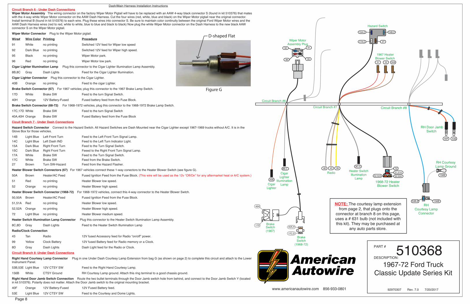
Dash/Main Harness Installation InstructionsCircuit Branch 6 - Under Dash ConnectionsWiper Motor Assembly The wiring connector on the factory Wiper Motor Pigtail will have to be replaced with an AAW 4-way black connector S (found in kit 510376) that mates with the 4-way white Wiper Motor connector on the AAW Dash Harness. Cut the four wires (red, white, blue and black) on the Wiper Motor pigtail near the original connector. Install terminal B (found in kit 510376) to each wire. Plug these wires into connector S. Be sure to maintain color continuity between the original Ford Wiper Motor wires and the AAW Dash Harness wires (red to red, white to white, blue to blue and black to black) Now plug the white Wiper Motor connector on the Dash Harness to the new black AAW connector S on the Wiper Motor pigtail.
Wiper Motor Connector Plug to the Wiper Motor pigtail.
Wire# Wire Color Printing Procedure91 White no printing Switched 12V feed for Wiper low speed
92 Dark Blue no printing Switched 12V feed for Wiper high speed.
95 Black no printing Wiper Motor park.
96 Red no printing Wiper Motor low park.
Cigar Lighter Illumination Lamp Plug this connector to the Cigar Lighter Illumination Lamp Assembly.
8B,8C Gray Dash Lights Feed for the Cigar Lighter Illumination.
Cigar Lighter Connector Plug this connector to the Cigar Lighter.
40B Orange no printing Feed to the cigar Lighter.
Brake Switch Connector (67) For 1967 vehicles; plug this connector to the 1967 Brake Lamp Switch.
17D White Brake SW Feed to the turn Signal Switch.
40H Orange 12V Battery-Fused Fused battery feed from the Fuse Block.
Brake Switch Connector (68-72) For 1968-1972 vehicles, plug this connector to the 1968-1972 Brake Lamp Switch.
17C,17D White Brake SW Feed to the turn Signal Switch
40A,40H Orange Brake SW Fused Battery feed from the Fuse Block
Cicuit Branch 7 - Under Dash ConnectionsHazard Switch Connector Connect to the Hazard Switch. All Hazard Switches are Dash Mounted near the Cigar Lighter except 1967-1969 trucks without A/C. It is in the Glove Box for those vehicles.
14B Light Blue Left Front Turn Feed to the Left Front Turn Signal Lamp.14C Light Blue Left Dash IND Feed to the Left Turn Indicator Light.15A Dark Blue Right Front Turn Feed to the Turn Signal Switch.15C Dark Blue Right Front Turn Feeed to the Right Front Turn Signal Lamp.17A White Brake SW Feed to the Turn Signal Switch.17C White Brake SW Feed from the Brake Switch.27 Brown Turn SW-Hazard Feed from the Hazard Flasher.
Heater Blower Switch Connectors (67) For 1967 vehicles connect these 1-way conectors to the Heater Blower Switch (see figure G).
50A Brown Heater/AC Feed Fused Ignition Feed from the Fuse Block. (This wire will be used as the 12v “Off/On” for any aftermarket heat or A/C system.)
51 Red no printing Heater Blower low speed.
52 Orange no printing Heater Blower high speed.
Heater Blower Switch Connector (1968-72) For 1968-1972 vehicles, connect this 4-way connector to the Heater Blower Swtch.
50,50A Brown Heater/AC Feed Fused Ignition Feed from the Fuse Block.
51,51A Red no printing Heater Blower low speed.
52,52A Orange no printing Heater Blower high speed.
72 Light Blue no printing Heater Blower medium speed.
Heater Switch Illumination Lamp Connector Plug this connector to the Heater Switch Illumination Lamp Assembly.
8C,8D Gray Dash Lights Feed to the Heater Switch Illumination Lamp
Radio/Clock Connection
43 Tan Radio 12V fused Accessory feed for Radio “on/off” power.
99 Yellow Clock Battery 12V fused Battery feed for Radio memory or a Clock.
8D Gray Dash Lights Dash Light feed for the Radio or Clock.
Circuit Branch 8 -Under Dash ConnectionsRight Hand Courtesy Lamp Connector Plug in one Under Dash Courtesy Lamp Extension from bag G (as shown on page 2) to complete this circuit and attach to the Lower Instrument Panel.
53B,53E Light Blue 12V CTSY SW Feed to the Right Hand Courtesy Lamp.
156B White CTSY Ground RH Courtesy Lamp ground. Attach this ring terminal to a good chassis ground.
Right Hand Door Jamb Switch Connection Route the two bullet terminals through the Door Jamb switch hole from behind, and connect to the Door Jamb Switch Y (located in kit 510376). Polarity does not matter. Attach the Door Jamb switch to the original mounting bracket.
40F Orange 12V Battery-Fused 12V Fused Battery feed.
53E Light Blue 12V CTSY SW Feed to the Courtesy and Dome Lights.
PART #
DESCRIPTION:510368
1967-72 Ford Truck Classic Update Series Kit
40A,H
17C,D
CigarLighter
40B
Wiper MotorAssembly Plug
BrakeSwitch
(1968-72)
9192
96 95
CigarLighter
IlluminationLamp
8B,C
40H
17D BrakeSwitch(1967)
Circuit Branch #7
Circuit Branch #6
15A,C
17A,C
14B,C
27
Hazard Switch
RHCourtesy Lamp
Connector
156B
156B53B,E
RH Courtesy Lamp Ground
Circuit Branch #8
RH Door JambSwitch
40F 53E
51 52 50A
Radio Heater SwitchIllumination
Lamp
99438C,D
8D 72
51,51A
50,50A52,52A
D-shaped Flat
Figure G
1967 HeaterBlower Switch
1968-72 HeaterBlower Switch
NOTE: The courtesy lamp extension from page 2, that plugs onto the
connector at branch 8 on this page, uses a # 631 bulb (not included with this kit). They may be purchased at
any auto parts store.
92970307 Rev. 7.0 7/20/2017

Page 9
Dash/Main Harness Installation Instructions
Circuit Branch 8 - Under Dash ConnectionsBlower Resistor Connectors Plug onto the blower Resistor see Figure J. Circuit 72 is not required for 1967 vehicles.
51A Red no printing Heater Blower low speed, all years.
52A,52B Orange no printing Heater Blower high speed, all years.
72 Light Blue no printing Heater Blower medium speed 1968-1972.
Blower Motor Connector Connect to the Blower Motor Pigtail.
52B Black no printing Blower Motor feed.
Circuit Branch 9 - Under Hood Connections RH Engine Compartment (Passenger Side) See page 11 Figure A for typical connections. For loose piece terminals and connectors, see parts kit 510376.
Starter Relay Connections Route wires 2A and 6 to the Starter Motor Relay location. See page 2 for the separate wire harnesses.
Alternator Output Circuit Obtain the Alternator Power Wire and Fusible Link Assembly (see page 2) from bag G and connect the ring terminal end (2H) with the blue fusible link to the battery terminal on the Starter Motor Relay. Route the other end (2) to the Alternator Battery stud, slide on sleeve D (from kit 510376) and install terminal L and attach this completed assembly to the battery stud of the Alternator (see page 11 figure D).
Wire# Wire Color Printing Procedure
2 Red no printing Alternator output wire.
2H Light Blue Fusible Link This is the Circuit protection for the Alternator output.
Main Power Feed to the Fuse Block Route wire 2A to the Starter Relay and cut to length. Install terminal C and insert into connector E (parts found in kit 510376) as shown on page 11. Obtain the Main Power Feed Fusible Link (see page 2) and plug into the same connector E (wire 2A). Now attach the eyelet end of the Main Power Feed Fusible Link (wire 2J) to the battery terminal of the starter relay (see page 11 figure D).
2A Red 12V Battery Main power feed.
2J Brown Fusible Link This is the Circuit protection for the main power output.
Start Circuit Route wire 6 to the Starter Relay and cut to length. Install sleeve D and crimp on terminal K (see parts kit 510376). Connect to the Starter relay S stud (see page 11, figure A).
6 Purple Starter Solenoid-S Start circuit.
Ignition Feed, Alternator Exciter Wire and Tachometer See page 11, figure A for typical connections.
Alternator Exciter Wire The wire 4D is the exciter wire for your alternator/voltage regulator. If you are using a one wire alternator, this wire will not be used and should be capped off as it is “hot” in the ignition “on” position. If you are using an alternator that requires an internal or external voltage regulator, this wire must be connected to the “switched or 12V ignition” terminal on your regulator or alternator according to the manufacturers specifications for the type of alternator/regulator that is being used. An inline diode or resistor may be necessary to eliminate “run on” after being switched off. AAW recommends a GEN 3 Internally Regulated or one wire alternator. If you are using a GM “SI” alternator, obtain the GM “SI” Alternator Exciter Wiring Harness (see page 2) from Bag G. Attach the eyelet end of wire 2G to the Alternator Battery stud (see figure D page 11). Route the 4D wire to the 2-way connector, which is part of the same Exciter Wiring Harness. Crimp on terminal B to wire 4D and insert into the open cavity of the 2-way connector. Now plug the 2-way connector into the “SI” alternator.
2G Red 12V Battery Battery wire for the GM “S” Alternator Exciter Wiring Harness.
4D Brown Alternator IGN Alternator Exciter wire.
Headlights Install Grommet Z in the RH Radiator Cor Support. Select the light green Headlight High Beam wire (11C) and the Low Beam wire (12A). Route these wires to the RH Headlight and cut to length, install terminal A, found in kit 510376, to each wire, and insert the wires into the Front Headlamp Extension Harness (see page 2) from Bag G. For proper circuit orientation, see page 11 Figure A.
11C Light Green Headlight-Hi Beam High Beam feed to the RH Headlight.
12A Tan Headlight-Low Beam Low Beam feed to the RH Headlight.
Front Headlamp Extension Harness This can be found in kit Bag G and is shown on page 2 and in figure A on page 11. The 150D ground wire ring terminal will attach to the original Headlamp ground wire location. The 150T female bullet ground wire will attach to the Park Lamp Assembly ground lead.
150D Black Ground This is the Headlight Ground.
150T Black Ground This is the Ground for the Park Lamp Assembly.
Right Hand Park/Turn Lamp & Socket Assembly NOTE: You will need to reuse the original Park/Turn Signal Lamp & Socket Assembly but will have to replace the 2-way bullet connector with a 2-way AAW connector (see figure A on page 11). Remove the old connector and crimp on terminals “W” (supplied in kit 510376) to the two wires and install the wires in the 2-way connector “V” (also supplied in kit 510376) as shown in figure A. The original Ford turn signal wire is white/blue (all years), the park lamp wire is black/yellow (67-69) or brown (70-72).
9A Brown Park Lights Park Light feed.
15C Dark Blue Right Front Turn Turn Signal feed.
Right Hand Park/turn Lamp Connector Select the brown Park Light wire (9A) and the dark blue Right Front Turn wire (15C). Route these wires to the RH Park/Turn Lamp and cut to length. Install terminal B, found in kit 510376, to each wire, and insert the wires into connector T. Be sure to align the AAW brown Park Light wire with the Ford Park Light wire (black/yellow or brown) and the AAW dark blue Right Front Turn wire with the Ford Right Front Turn wire (white/blue).
9A Brown Park Lights Park Light feed.
15C Dark Blue Right Front Turn Turn Signal feed.
Horn Connection Route wire (29) to the RH Horn and cut to length. If the vehicle has only one Horn (it will be on the right side of the radiator), crimp on terminal “B” and insert into connector “N” and attach to the RH Horn. If there are two horns, double the wire that was just cut with wire (29) and crimp on terminal “C” instead of “B” and insert into connector “N” and attach to the RH Horn. Route the loose wire to the LH Horn (which is on the left side of the radiator) and crimp on terminal “B” and insert into connector “N” and attach to the LH Horn. All of the terminals and connectors will be found in kit 510376.
29 Dark Green Horn Horn feed.
PART #
DESCRIPTION:510368
1967-72 Ford Truck Classic Update Series Kit
Starter Solenoid
Main Power Feed
Alternator Exciter
Circuit Branch #9
Blower Resistor
Horn
RH FrontLighting
4D
29
12A11C9A15C
62A
RH EngineCompt. Wiring
72 51A 52A,B
52B
www.americanautowire.com 856-933-0801
Blower Resistor
72
51A 52A,B
52B
Blower High Speed
BlowerMediumSpeed
BlowerLow Speed
Figure J
To BlowerMotor
Circuit Branch #8
92970307 Rev. 7.0 7/20/2017
www.americanautowire.com 856-933-0801
Page 10
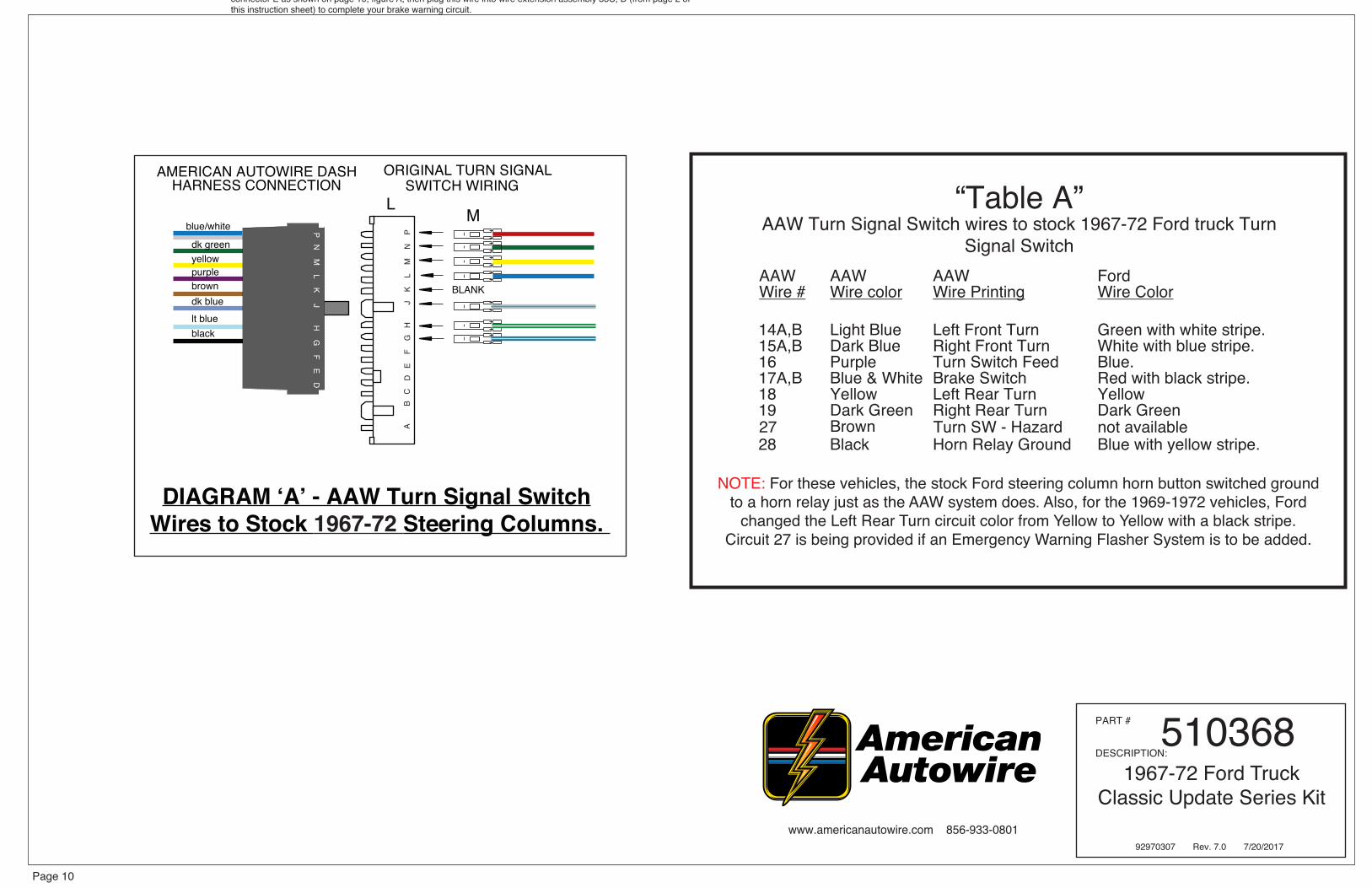
AAW AAW AAW FordWire # Wire color Wire Printing Wire Color
14A,B Light Blue Left Front Turn Green with white stripe.15A,B Dark Blue Right Front Turn White with blue stripe.16 Purple Turn Switch Feed Blue.17A,B Blue & White Brake Switch Red with black stripe.18 Yellow Left Rear Turn Yellow19 Dark Green Right Rear Turn Dark Green
28 Black Horn Relay Ground Blue with yellow stripe.
“Table A” AAW Turn Signal Switch wires to stock 1967-72 Ford truck Turn
Signal Switch
NOTE: For these vehicles, the stock Ford steering column horn button switched ground to a horn relay just as the AAW system does. Also, for the 1969-1972 vehicles, Ford
changed the Left Rear Turn circuit color from Yellow to Yellow with a black stripe.Circuit 27 is being provided if an Emergency Warning Flasher System is to be added.
PART #
DESCRIPTION:510368
1967-72 Ford Truck Classic Update Series Kit
92970307 Rev. 7.0 7/20/2017
DIAGRAM ‘A’ - AAW Turn Signal Switch Wires to Stock 1967-72 Steering Columns.
ORIGINAL TURN SIGNAL
blue/white
BLANK
dk greenyellowpurplebrowndk bluelt blueblack
AMERICAN AUTOWIRE DASH HARNESS CONNECTION
P N M
L K J H G
F E D
SWITCH WIRINGL
A
B
C
D
E
F
G
H
J
K
L
M
N
P
M
27 Brown Turn SW - Hazard not available
Brake Pressure Differentail Switch (NOTE:) We have provided you with the connection to the original Ford brake warning switch in the form of a wire extension assembly (wires 33C, D on page 2 of this instruction sheet). You will plug this extension onto wire 33, below.
33B Tan Brake Switch Route this wire to the brake warning switch area near the master cylinder, cut to length, install terminal B, plug into connector E as shown on page 10, figure A, then plug this wire into wire extension assembly 33C, D (from page 2 of this instruction sheet) to complete your brake warning circuit.

to RH horn
RH core support grommet
D
G
B or CN
NOTE: Install one large main grommet (G) into the passengers’s side firewall pass thru opening and the grommet R into the center
firewall pass thru opening (grommets included in the 510376 kit), then pass the wiring from branches 6 and 9 thru those grommets. After completing these tasks, apply silicone sealer to these areas to make a weather tight seal.
RH headlamp, RH parking lamp, engine, main power, tachometer,alternator ignition and power, horn, and starter solenoid connections.
NOTE: The terminals and connectors listed on this page and denoted with UPPER CASE LETTERS are to help you complete the various connections to your lamps, engine connections, switches, horn, etc. They can all be found in your loose piece clamp, parts kit, P/N 510376.
AAW suggests and recommends using pages 7 and 9 to complete the installation of the RH forward lamp, turn, various engine functions, horn, starter solenoid, tachometer, alternator exciter and power connections, and the main power feed.
AAW kits are all engineered to be used in conjunction with a high output, later model internally regulated, or one wire alternator. We do not suggest or support the use of a stock low amperage alternator as they do not supply sufficient current to recharge the battery in a highly modified truck such as this kit was designed for. AAW suggests a Ford Gen III, a GM “SI”, or a 1 wire type alternator as good choices to use. An adpater to complete the connection to the Ford Gen III style alter-nator (AAW p/n 500802) may be purchased separately. Contact AAW for your needs.
www.americanautowire.com 856-933-0801
Page 11
(optional)
M
K
choke feed
ballastresistor
(resistor not included.
(this wire not supplied)
(optional typical points type system shown here)
Used on point type and someaftermarket ignition systems)oil sending
to coil “+” side coil
electric
N B
unit
Figure “D”
Fusible Link
StarterSolenoid
To alternator ”BAT” stud
"BAT"
(positive cable
Main system power feed and alternator connections.
2J
2H
Fusible Link S I
here also)attaches
stud
Main Power and
C
C P
E
S IS I
purple
N B
B Q
(optional)
M
"BAT"
to starter output stud
S I
to optional
BN
D L (large)
Plug completed red wire 2A, in Figure A above, into 2J.
Alternator Wiring
alternator
Figure “A”, Branches #6 and #9 Passenger’s Side
Location
red
to TACH “-” location on coil
white
pink
white
distributorto BAT “+”location on coil
alternator
alternatorignition wire
brown brown dk bluedk blue
temperature sending unit
dk greendk green
These wires are all found at branches 6 and
9 on pages 7 and 9
Plug this completed
red wire into 2J in Figure D
on page 11
tan
dk green
(optional GM HEI)
(optional GM HEI)
PART #
DESCRIPTION:510368
1967-72 Ford Truck Classic Update Series Kit
dk blue
lt green
tan
black
right headlight
AA
lt greentan
brown
"BAT" stud
B
GM “SI” extensionfrom page 2
Brown Alternator
Ignition wire from Figure “A”;
see above.
2
LH hornfront H/L extension
from page 2
2J
BVW(2 places)
original parking lamp pigtail (not included
with this kit)
(2 places)T
R
J
J
Z
parking lamp ground lead (not included
with this kit)
150T
150D
29
35
31
4D
2A
3F
39D
6
9A
15C
11C
12A
121
4D
2G
92970307 Rev. 7.0 7/20/2017
to electric fan
to windshieldwasher pump
recommended fan relay(not included in this kit)
(from rear body kit 510371)
www.americanautowire.com 856-933-0801
Rear Body Leads
Page 12
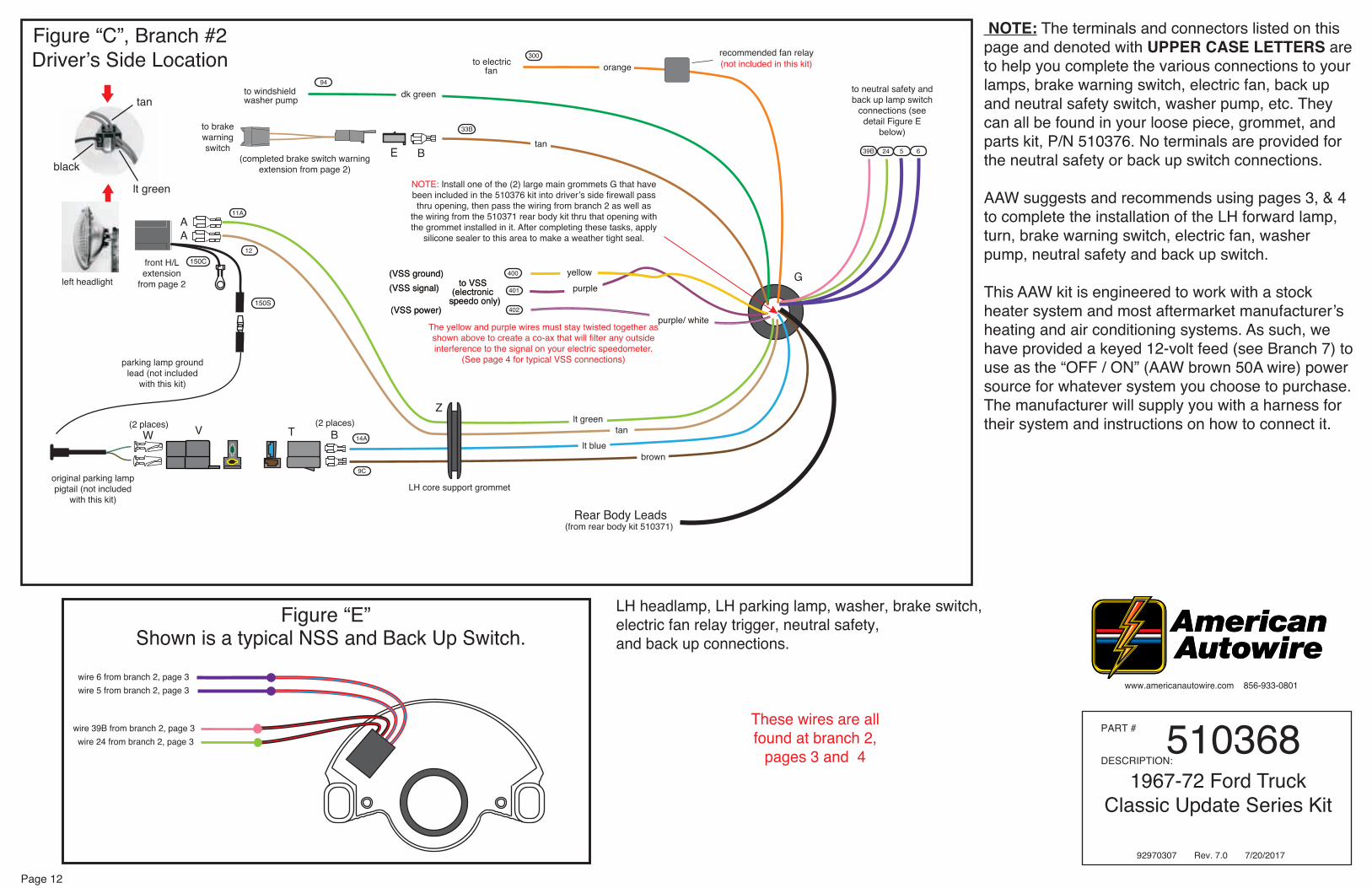
NOTE: The terminals and connectors listed on this page and denoted with UPPER CASE LETTERS are to help you complete the various connections to your lamps, brake warning switch, electric fan, back up and neutral safety switch, washer pump, etc. They can all be found in your loose piece, grommet, and parts kit, P/N 510376. No terminals are provided for the neutral safety or back up switch connections.
AAW suggests and recommends using pages 3, & 4 to complete the installation of the LH forward lamp, turn, brake warning switch, electric fan, washer pump, neutral safety and back up switch.
This AAW kit is engineered to work with a stock heater system and most aftermarket manufacturer’s heating and air conditioning systems. As such, we have provided a keyed 12-volt feed (see Branch 7) to use as the “OFF / ON” (AAW brown 50A wire) power source for whatever system you choose to purchase. The manufacturer will supply you with a harness for their system and instructions on how to connect it.
G
B
NOTE: Install one of the (2) large main grommets G that have been included in the 510376 kit into driver’s side firewall pass thru opening, then pass the wiring from branch 2 as well as
the wiring from the 510371 rear body kit thru that opening with the grommet installed in it. After completing these tasks, apply
silicone sealer to this area to make a weather tight seal.
LH headlamp, LH parking lamp, washer, brake switch,electric fan relay trigger, neutral safety, and back up connections.
lt bluebrown
lt green
tan
black
left headlight
AA
lt greentan
orange
yellowpurpleto VSS
(electronic speedo only)
(VSS ground)(VSS signal)
(VSS power)
yellowpurple
purple/ white
to VSS(electronic
speedo only)
(VSS ground)(VSS signal)
(VSS power)
tan
These wires are all found at branch 2,
pages 3 and 4
The yellow and purple wires must stay twisted together as shown above to create a co-ax that will filter any outside interference to the signal on your electric speedometer.
(See page 4 for typical VSS connections)
Figure “C”, Branch #2 Driver’s Side Location
to neutral safety and back up lamp switch
connections (see detail Figure E
below)
PART #
DESCRIPTION:510368
1967-72 Ford Truck Classic Update Series Kit
VW(2 places)
original parking lamp pigtail (not included
with this kit)
front H/L extension
from page 2
(2 places)T
Z
parking lamp ground lead (not included
with this kit)
LH core support grommet
9C
14A
11A
33B
39B 24 5 6
12
94
300
400
401
402150S
150C
92970307 Rev. 7.0 7/20/2017
dk green
Figure “E”Shown is a typical NSS and Back Up Switch.
wire 6 from branch 2, page 3
wire 39B from branch 2, page 3wire 24 from branch 2, page 3
wire 5 from branch 2, page 3
E B
to brakewarningswitch
(completed brake switch warningextension from page 2)

www.americanautowire.com 856-933-0801
Page 13
NOTE: Above, you will find a photograph of the completed Fuse Block assembly depicting the proper location for the
installation of each fuse and the two flasher cans.
FUSE AND FLASHER LOCATIONS
PART #
DESCRIPTION:510368
1967-72 Ford Truck Classic Update Series Kit
92970307 Rev. 7.0 7/20/2017
www.americanautowire.com 856-933-0801
Page 14
PART #
DESCRIPTION:510368
1967-72 Ford Truck Classic Update Series Kit
92970307 Rev. 7.0 7/20/2017
This page intentionally left blank.