Classic Line-Einfachhubmagnete für industielle Anwendungen ...
28
Classic Line Single-Stroke Solenoids for Industrial Applications
Transcript of Classic Line-Einfachhubmagnete für industielle Anwendungen ...
Classic Line
Single-Stroke Solenoids for Industrial Applications

2
Kendrion - Industrial Magnetic Systems
We develop solutions!Kendrion develops, manufactures and markets high-quality electromagnetic systems and components for industrial and automotive applications. For over a century, we have been engineering precision parts for the world’s leading innovators in passenger cars, commercial vehicles and industrial applications.
As a leading technology pioneer, Kendrion invents, designs and manufactures complex components and customised systems as well as local solutions on demand. We are committed to the engineering challenges of tomorrow and taking responsibility for how we source, manufacture and conduct business is embedded into our culture of innovation. Rooted in Germany, headquartered in the Netherlands and listed on the Amsterdam stock exchange, Kendrion`s expertise extends across Europe to the Americas and Asia.
Created with passion and engineered with precision.
In the business unit Industrial Magnetic Systems (IMS) the focus lies on electromagnetic actuators and mecha-tronic assemblies for applications in power engineering, safety engineering, machine building, automation technology and other industries. With the experience of our traditional brands Binder, Neue Hahn Magnet and Thoma Magnettechnik we are successful in our markets as an industry expert with a high technological competence.
We offer you both customer-specific and standardised products. Our assemblies are based on powerful and reliable single-stroke, holding, locking, spreader, control, rotary, vibratory solenoids and solenoid valves.We always think in terms of solutions.
Our strength lies in new developments for our customers. Our engineers are specialists for innovative products with optimum technical properties. Furthermore, we develop mechanical assemblies, modern drive electronics and sensor systems to your requirements.
Our products are manufactured in Germany at the parent companies Donaueschingen and Engelswies as well as in the USA, China and Romania. This ensures efficient project management and a needs-oriented delivery for our internationally operating customers.
By means of segmented production areas we can implement both small quantities and large series with an optimum degree of automation.
We guarantee top quality.All products are tested and developed in compliance with the norm DIN VDE 0580 for electromagnetic devices and components or according to industry-specific standards of our customers. In many cases our products are tested and certified by external associations, among others according to the CSA, VdS and ATEX guidelines. Our quality management system is certified according to DIN EN ISO 9001, and our environmental management system fulfils the norm ISO 14001.
With our subsidiaries in Austria, Italy, the USA, China and our worldwide distribution network we are your ideal partner on site.
Kendrion – We magnetise the world
www.kendrion.com
3
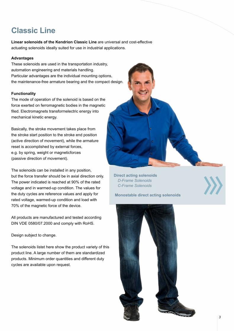
Classic LineLinear solenoids of the Kendrion Classic Line are universal and cost-effectiveactuating solenoids ideally suited for use in industrial applications.
AdvantagesThese solenoids are used in the transportation industry,automation engineering and materials handling. Particular advantages are the individual mounting options, the maintenance-free armature bearing and the compact design.
Functionality The mode of operation of the solenoid is based on the force exerted on ferromagnetic bodies in the magnetic filed. Electromagnets transformelectric energy into mechanical kinetic energy.
Basically, the stroke movement takes place from the stroke start position to the stroke end position (active direction of movement), while the armaturereset is accomplished by external forces, e.g. by spring, weight or magneticforces (passive direction of movement).
The solenoids can be installed in any position,but the force transfer should be in axial direction only. The power indicated is reached at 90% of the rated voltage and in warmed-up condition. The values for the duty cycles are reference values and apply for rated voltage, warmed-up condition and load with 70% of the magnetic force of the device.
All products are manufactured and tested according DIN VDE 0580/07.2000 and comply with RoHS.
Design subject to change.
The solenoids listet here show the product variety of thisproduct line. A large number of them are standardized products. Minimum order quantities and different duty cycles are available upon request.
Direct acting solenoids D-Frame Solenoids
C-Frame Solenoids
Monostable direct acting solenoids
Classic Line
4
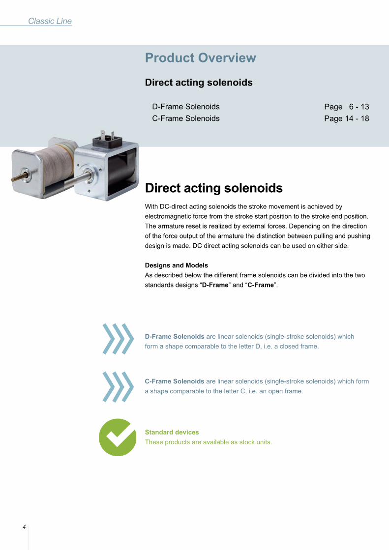
D-Frame Solenoids are linear solenoids (single-stroke solenoids) which form a shape comparable to the letter D, i.e. a closed frame.
C-Frame Solenoids are linear solenoids (single-stroke solenoids) which form a shape comparable to the letter C, i.e. an open frame.
Standard devicesThese products are available as stock units.
Product Overview
Direct acting solenoids D-Frame Solenoids C-Frame Solenoids
Page 6 - 13Page 14 - 18
Direct acting solenoidsWith DC-direct acting solenoids the stroke movement is achieved by electromagnetic force from the stroke start position to the stroke end position. The armature reset is realized by external forces. Depending on the direction of the force output of the armature the distinction between pulling and pushing design is made. DC direct acting solenoids can be used on either side.
Designs and Models As described below the different frame solenoids can be divided into the two standards designs “D-Frame” and “C-Frame”.

5
Monostable direct acting solenoidThe single-stroke solenoid in monostable design equipped with a permanent magnet keeps the armature currentless in stroke end position.The magnetic field is neutralized by negative coil energization and the armature can be reset to stroke start position by external forces.
BenefitsEnergy savings, safety in case of power failure, reduced dimensions, weight and cost savings as well as almost constant magnetic forces allow for a vari-ety of applications in office machine and apparatus engineering, in automa-tion, in textile machines, in control systems and in automobile manufacturing.
Monostable directacting solenoid AccessoriesTechnical Explanations
Page 19 - 20
Page 21 - 23Page 24 - 25
Page 6 - 13Page 14 - 18
D-Frame Solenoids
6
Accessories
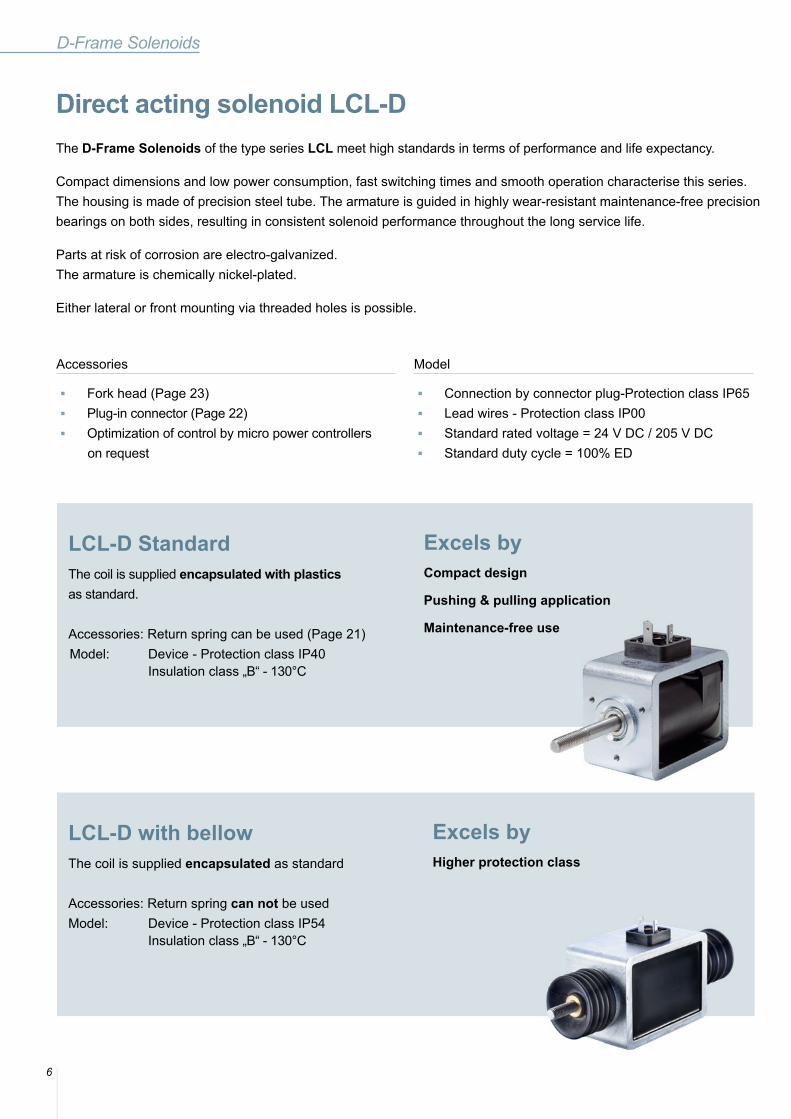
LCL-D StandardThe coil is supplied encapsulated with plastics as standard.
Accessories: Return spring can be used (Page 21)Model: Device - Protection class IP40 Insulation class „B“ - 130°C
Excels byCompact design
Pushing & pulling application
Maintenance-free use
Direct acting solenoid LCL-DThe D-Frame Solenoids of the type series LCL meet high standards in terms of performance and life expectancy.
Compact dimensions and low power consumption, fast switching times and smooth operation characterise this series.The housing is made of precision steel tube. The armature is guided in highly wear-resistant maintenance-free precision bearings on both sides, resulting in consistent solenoid performance throughout the long service life.
Parts at risk of corrosion are electro-galvanized.The armature is chemically nickel-plated.
Either lateral or front mounting via threaded holes is possible.
■ Fork head (Page 23) ■ Plug-in connector (Page 22) ■ Optimization of control by micro power controllers
on request
Model
■ Connection by connector plug-Protection class IP65 ■ Lead wires - Protection class IP00 ■ Standard rated voltage = 24 V DC / 205 V DC ■ Standard duty cycle = 100% ED
LCL-D with bellow The coil is supplied encapsulated as standard
Accessories: Return spring can not be used Model: Device - Protection class IP54 Insulation class „B“ - 130°C
Excels byHigher protection class
7
LCL-D Standard LCL-D with bellow
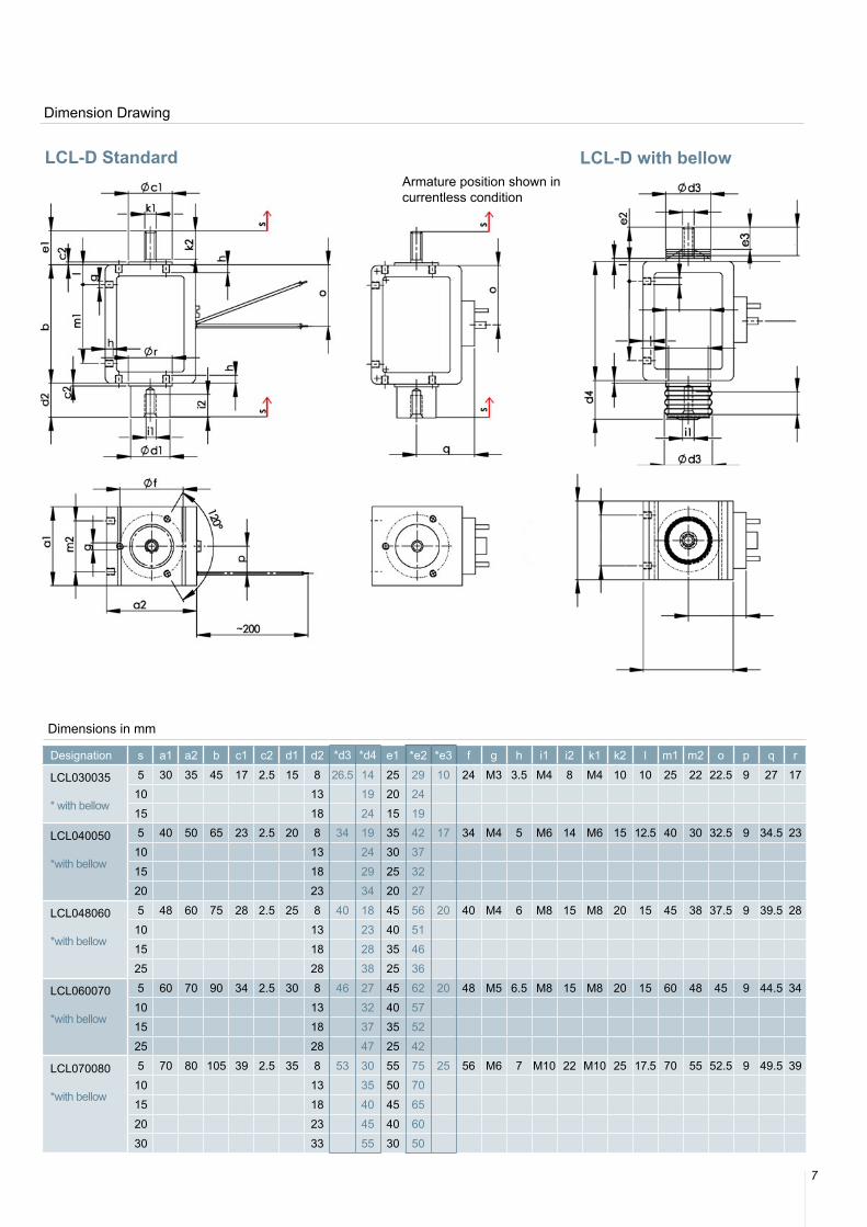
Dimension Drawing
Armature position shown incurrentless condition
Dimensions in mm
Designation s a1 a2 b c1 c2 d1 d2 *d3 *d4 e1 *e2 *e3 f g h i1 i2 k1 k2 l m1 m2 o p q r
LCL030035
* with bellow
5 30 35 45 17 2.5 15 8 26.5 14 25 29 10 24 M3 3.5 M4 8 M4 10 10 25 22 22.5 9 27 1710 13 19 20 2415 18 24 15 19
LCL040050
*with bellow
5 40 50 65 23 2.5 20 8 34 19 35 42 17 34 M4 5 M6 14 M6 15 12.5 40 30 32.5 9 34.5 2310 13 24 30 3715 18 29 25 3220 23 34 20 27
LCL048060
*with bellow
5 48 60 75 28 2.5 25 8 40 18 45 56 20 40 M4 6 M8 15 M8 20 15 45 38 37.5 9 39.5 2810 13 23 40 5115 18 28 35 4625 28 38 25 36
LCL060070
*with bellow
5 60 70 90 34 2.5 30 8 46 27 45 62 20 48 M5 6.5 M8 15 M8 20 15 60 48 45 9 44.5 3410 13 32 40 5715 18 37 35 5225 28 47 25 42
LCL070080
*with bellow
5 70 80 105 39 2.5 35 8 53 30 55 75 25 56 M6 7 M10 22 M10 25 17.5 70 55 52.5 9 49.5 3910 13 35 50 7015 18 40 45 6520 23 45 40 6030 33 55 30 50
8
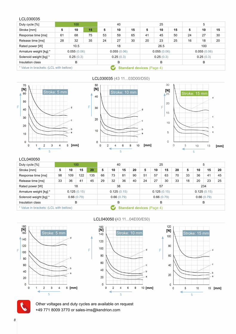
LCL040050 (43 11...04E00/E50)
LCL030035 (43 11...03D00/D50)
LCL030035Duty cycle [%] 100 40 25 5Stroke [mm] 5 10 15 5 10 15 5 10 15 5 10 15Response time [ms] 61 68 75 53 59 65 41 45 50 24 27 30Release time [ms] 28 32 35 24 27 30 20 23 25 16 18 20Rated power [W] 10.5 18 26.5 100Armature weight [kg] * 0.055 (0.06) 0.055 (0.06) 0.055 (0.06) 0.055 (0.06)Solenoid weight [kg] * 0.25 (0.3) 0.25 (0.3) 0.25 (0.3) 0.25 (0.3)Insulation class B B B B* Value in brackets: (LCL with bellow) Standard devices (Page 4)
[N]
[mm]
s
Stroke: 5 mm[N]
[mm]
s
Stroke: 10 mm [N]
[mm]
s
Stroke: 15 mm
[N]
[mm]
s
Stroke: 5 mm[N]
[mm]
[N]
[mm]
s s
Stroke: 10 mm Stroke: 15 mm
LCL040050Duty cycle [%] 100 40 25 5Stroke [mm] 5 10 15 20 5 10 15 20 5 10 15 20 5 10 15 20Response time [ms] 98 109 122 135 66 73 81 90 51 57 63 70 33 36 41 45
Release time [ms] 33 36 41 45 29 32 36 40 24 27 30 33 18 20 23 25
Rated power [W] 18 38 57 234
Armature weight [kg] * 0.125 (0.15) 0.125 (0.15) 0.125 (0.15) 0.125 (0.15)
Solenoid weight [kg] * 0.66 (0.79) 0.66 (0.79) 0.66 (0.79) 0.66 (0.79)
Insulation class B B B B* Value in brackets: (LCL with bellow) Standard devices (Page 4)
Other voltages and duty cycles are available on request+49 771 8009 3770 or [email protected]
9
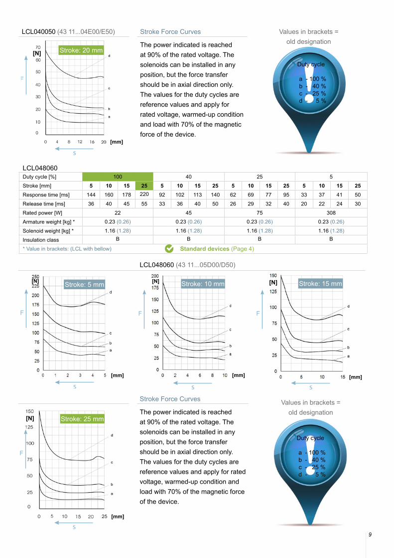
LCL040050 (43 11...04E00/E50) Stroke Force Curves
The power indicated is reached at 90% of the rated voltage. The solenoids can be installed in any position, but the force transfer should be in axial direction only. The values for the duty cycles are reference values and apply for rated voltage, warmed-up condition and load with 70% of the magnetic force of the device.
Duty cycle
a - 100 % b - 40 % c - 25 % d - 5 %
[N]
[mm]
s
Stroke: 20 mm
Values in brackets = old designation
LCL048060Duty cycle [%] 100 40 25 5Stroke [mm] 5 10 15 25 5 10 15 25 5 10 15 25 5 10 15 25Response time [ms] 144 160 178 220 92 102 113 140 62 69 77 95 33 37 41 50Release time [ms] 36 40 45 55 33 36 40 50 26 29 32 40 20 22 24 30Rated power [W] 22 45 75 308Armature weight [kg] * 0.23 (0.26) 0.23 (0.26) 0.23 (0.26) 0.23 (0.26)
Solenoid weight [kg] * 1.16 (1.28) 1.16 (1.28) 1.16 (1.28) 1.16 (1.28)
Insulation class B B B B
* Value in brackets: (LCL with bellow) Standard devices (Page 4)
LCL048060 (43 11...05D00/D50)
Stroke Force Curves
The power indicated is reached at 90% of the rated voltage. The solenoids can be installed in any position, but the force transfer should be in axial direction only. The values for the duty cycles are reference values and apply for rated voltage, warmed-up condition and load with 70% of the magnetic force of the device.
Duty cycle
a - 100 % b - 40 % c - 25 % d - 5 %
[N]
[mm]
s
Stroke: 5 mm [N]
[mm]
s
Stroke: 10 mm [N]
[mm]
s
Stroke: 15 mm
[N]
[mm]
s
Stroke: 25 mm
Values in brackets = old designation
10
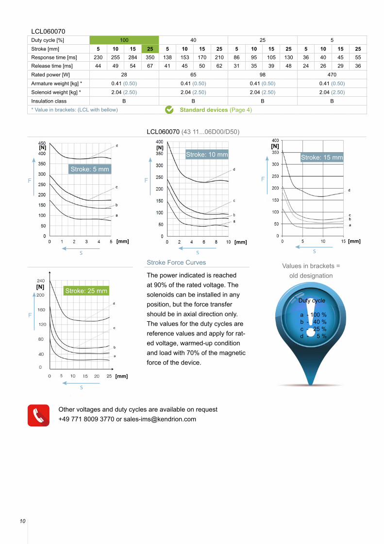
LCL060070 (43 11...06D00/D50)
Stroke Force Curves
The power indicated is reached at 90% of the rated voltage. The solenoids can be installed in any position, but the force transfer should be in axial direction only. The values for the duty cycles are reference values and apply for rat-ed voltage, warmed-up condition and load with 70% of the magnetic force of the device.
Duty cycle
a - 100 % b - 40 % c - 25 % d - 5 %
Stroke: 25 mm
LCL060070Duty cycle [%] 100 40 25 5Stroke [mm] 5 10 15 25 5 10 15 25 5 10 15 25 5 10 15 25Response time [ms] 230 255 284 350 138 153 170 210 86 95 105 130 36 40 45 55Release time [ms] 44 49 54 67 41 45 50 62 31 35 39 48 24 26 29 36Rated power [W] 28 65 98 470Armature weight [kg] * 0.41 (0.50) 0.41 (0.50) 0.41 (0.50) 0.41 (0.50)Solenoid weight [kg] * 2.04 (2.50) 2.04 (2.50) 2.04 (2.50) 2.04 (2.50)Insulation class B B B B* Value in brackets: (LCL with bellow) Standard devices (Page 4)
[N]
[mm]
s
Stroke: 5 mm
[N]
[mm]
s
[N]
[mm]
s
[N]
[mm]
s
Values in brackets = old designation
Other voltages and duty cycles are available on request+49 771 8009 3770 or [email protected]
Stroke: 10 mm Stroke: 15 mm
11
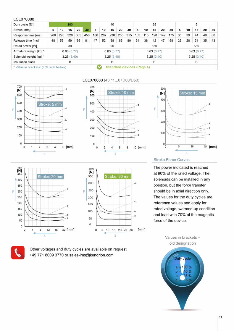
LCL070080 (43 11...07D00/D50)
Stroke Force Curves
The power indicated is reached at 90% of the rated voltage. The solenoids can be installed in any position, but the force transfer should be in axial direction only. The values for the duty cycles are reference values and apply for rated voltage, warmed-up condition and load with 70% of the magnetic force of the device.
LCL070080Duty cycle [%] 100 40 25 5Stroke [mm] 5 10 15 20 30 5 10 15 20 30 5 10 15 20 30 5 10 15 20 30Response time [ms] 266 295 328 365 450 186 207 230 255 315 103 115 128 142 175 35 39 44 49 60Release time [ms] 48 53 59 66 81 47 52 58 65 80 34 38 42 47 58 25 28 31 35 43Rated power [W] 39 95 150 680Armature weight [kg] * 0.63 (0.77) 0.63 (0.77) 0.63 (0.77) 0.63 (0.77)Solenoid weight [kg] * 3.25 (3.40) 3.25 (3.40) 3.25 (3.40) 3.25 (3.40)Insulation class B B B B* Value in brackets: (LCL with bellow) Standard devices (Page 4)
Stroke: 30 mm
[N]
[mm]
s
Stroke: 5 mm
[N]
[mm]
s
Stroke: 10 mm [N]
[mm]
s
Stroke: 15 mm
[N]
[mm]
s
Stroke: 20 mm[N]
[mm]
s Values in brackets = old designation
Duty cycle
a - 100 % b - 40 % c - 25 % d - 5 %
Other voltages and duty cycles are available on request+49 771 8009 3770 or [email protected]
D-Frame Solenoids
12
Dimension Drawing
Accessories
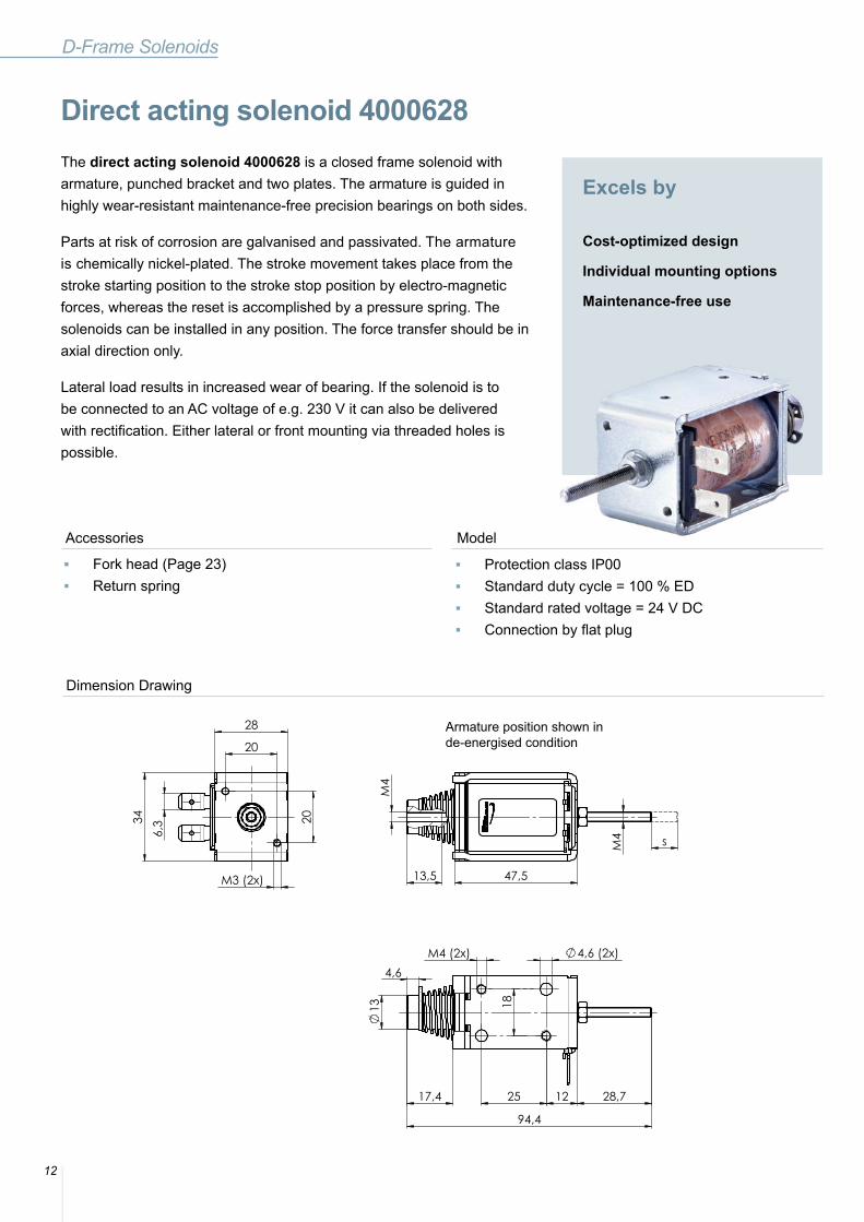
The direct acting solenoid 4000628 is a closed frame solenoid with armature, punched bracket and two plates. The armature is guided in highly wear-resistant maintenance-free precision bearings on both sides. Parts at risk of corrosion are galvanised and passivated. The armature is chemically nickel-plated. The stroke movement takes place from the stroke starting position to the stroke stop position by electro-magnetic forces, whereas the reset is accomplished by a pressure spring. The solenoids can be installed in any position. The force transfer should be in axial direction only.
Lateral load results in increased wear of bearing. If the solenoid is to be connected to an AC voltage of e.g. 230 V it can also be delivered with rectification. Either lateral or front mounting via threaded holes is possible.
Model
Direct acting solenoid 4000628
Excels by
Cost-optimized design
Individual mounting options
Maintenance-free use
M4
13,5 47,5
M4 s 6
,3
20
28
20
34
M3 (2x)
M4 (2x) 4,6 (2x)
18
12 25 28,7 17,4
94,4
13
4,6
Armature position shown inde-energised condition
■ Fork head (Page 23) ■ Return spring
■ Protection class IP00 ■ Standard duty cycle = 100 % ED ■ Standard rated voltage = 24 V DC ■ Connection by flat plug

13
4000628Duty cycle [%] 100 40 5
Stroke [mm] 10Rated power [W] 13.4 25.6 180
Armature weight [kg] * 0.046
Solenoid weight [kg] * 0.225
Insulation class F
Technical Data
Other voltages and duty cycles are available on request +49 771 8009 3770 or [email protected]
Stroke Force Curves 4000628
The power indicated is reached at 90% of the rated voltage. The solenoids can be installed in any position, but the force transfer should be in axial direction only. The values for the duty cycles are reference values and apply for rated voltage, warmed-up condition and load with 70% of the magnetic force of the device.
ab
d
[N]
[mm]
s
Duty cycle
a - 100 % b - 40 % d - 5 %
C-Frame Solenoids
14
Accessories
Excels by
Cost-optimized design
Return by return spring
Compact design
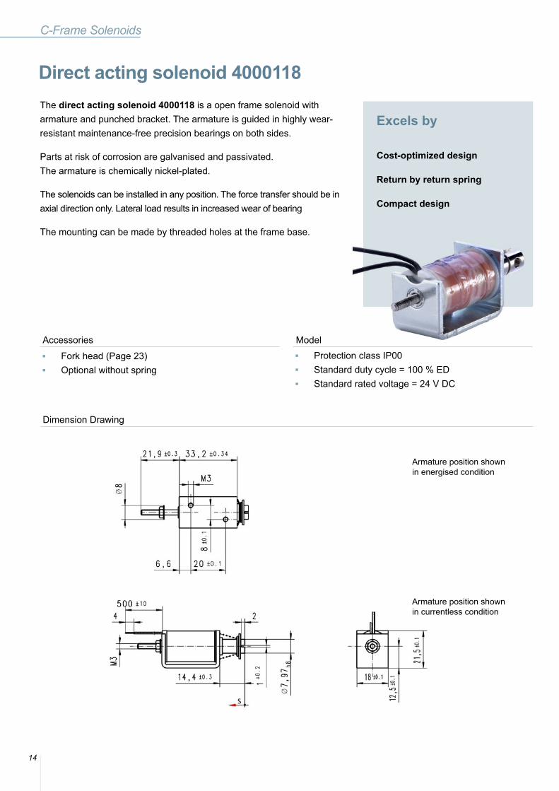
The direct acting solenoid 4000118 is a open frame solenoid with armature and punched bracket. The armature is guided in highly wear-resistant maintenance-free precision bearings on both sides.
Parts at risk of corrosion are galvanised and passivated. The armature is chemically nickel-plated.
The solenoids can be installed in any position. The force transfer should be in axial direction only. Lateral load results in increased wear of bearing
The mounting can be made by threaded holes at the frame base.
Model
Direct acting solenoid 4000118
Dimension Drawing
■ Fork head (Page 23) ■ Optional without spring
■ Protection class IP00 ■ Standard duty cycle = 100 % ED ■ Standard rated voltage = 24 V DC
Armature position shownin energised condition
Armature position shownin currentless condition
15
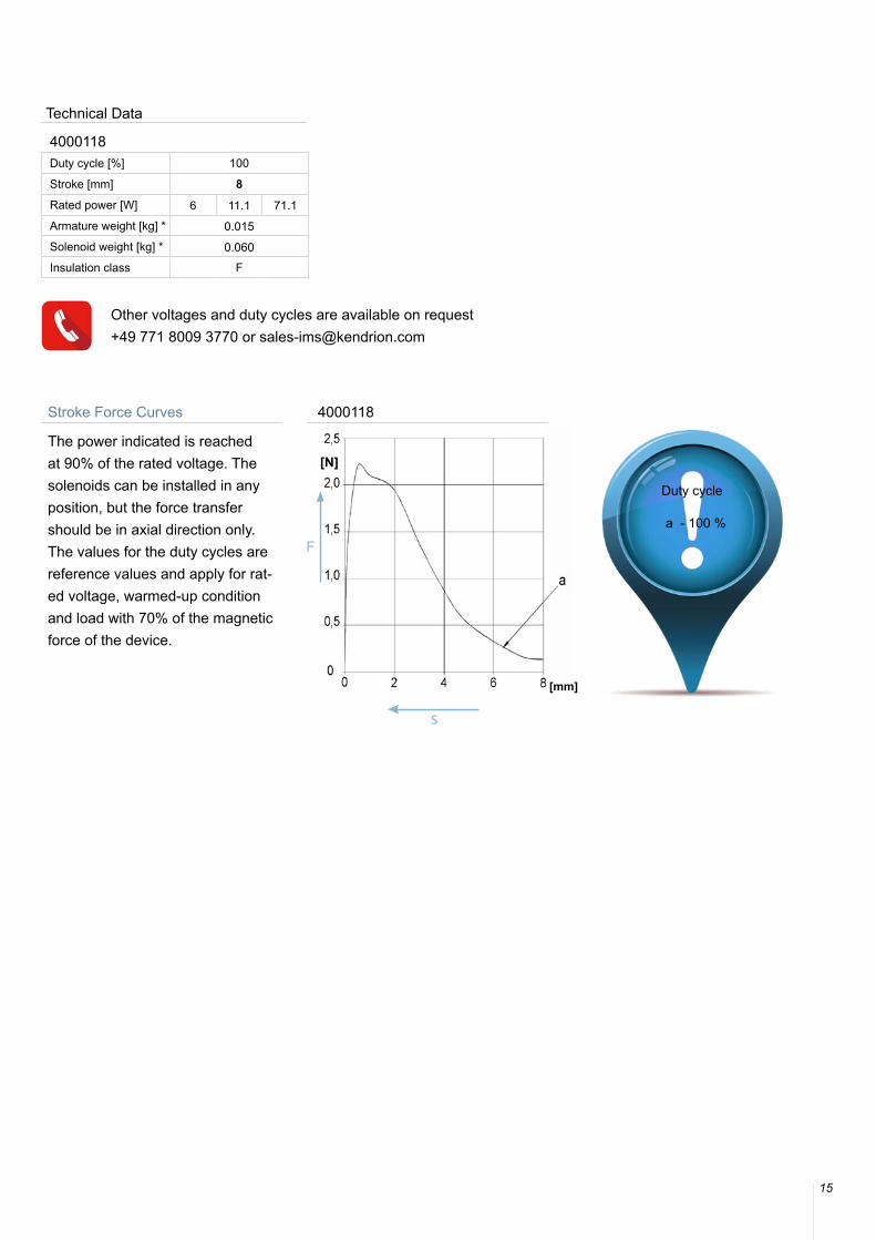
Stroke Force Curves 4000118
The power indicated is reached at 90% of the rated voltage. The solenoids can be installed in any position, but the force transfer should be in axial direction only. The values for the duty cycles are reference values and apply for rat-ed voltage, warmed-up condition and load with 70% of the magnetic force of the device.
4000118Duty cycle [%] 100
Stroke [mm] 8Rated power [W] 6 11.1 71.1
Armature weight [kg] * 0.015
Solenoid weight [kg] * 0.060
Insulation class F
Technical Data
Other voltages and duty cycles are available on request +49 771 8009 3770 or [email protected]
Duty cycle
a - 100 %
s
[N]
[mm]
16
Accessories
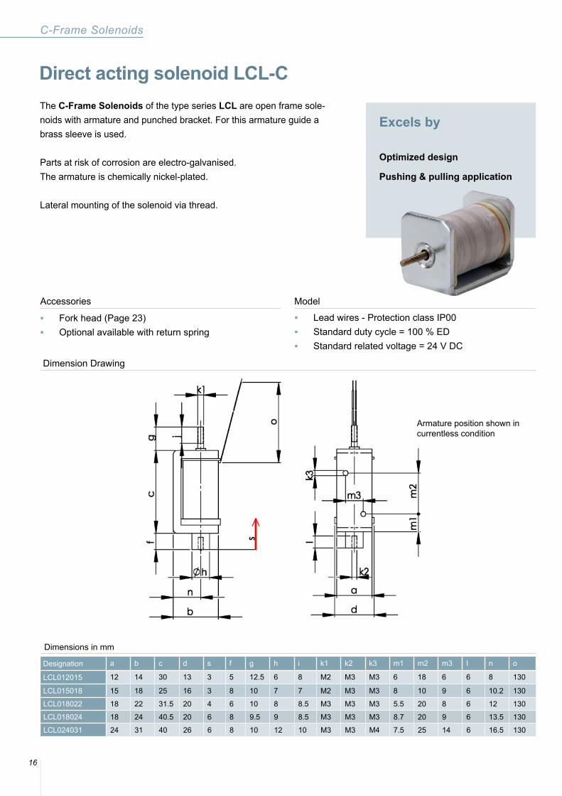
Excels by
Optimized design
Pushing & pulling application
The C-Frame Solenoids of the type series LCL are open frame sole-noids with armature and punched bracket. For this armature guide a brass sleeve is used.
Parts at risk of corrosion are electro-galvanised. The armature is chemically nickel-plated.
Lateral mounting of the solenoid via thread.
Model
Dimensions in mm
Designation a b c d s f g h i k1 k2 k3 m1 m2 m3 I n o
LCL012015 12 14 30 13 3 5 12.5 6 8 M2 M3 M3 6 18 6 6 8 130
LCL015018 15 18 25 16 3 8 10 7 7 M2 M3 M3 8 10 9 6 10.2 130
LCL018022 18 22 31.5 20 4 6 10 8 8.5 M3 M3 M3 5.5 20 8 6 12 130
LCL018024 18 24 40.5 20 6 8 9.5 9 8.5 M3 M3 M3 8.7 20 9 6 13.5 130
LCL024031 24 31 40 26 6 8 10 12 10 M3 M3 M4 7.5 25 14 6 16.5 130
C-Frame Solenoids
Direct acting solenoid LCL-C
Dimension Drawing
■ Fork head (Page 23) ■ Optional available with return spring
■ Lead wires - Protection class IP00 ■ Standard duty cycle = 100 % ED ■ Standard related voltage = 24 V DC
Armature position shown incurrentless condition
17
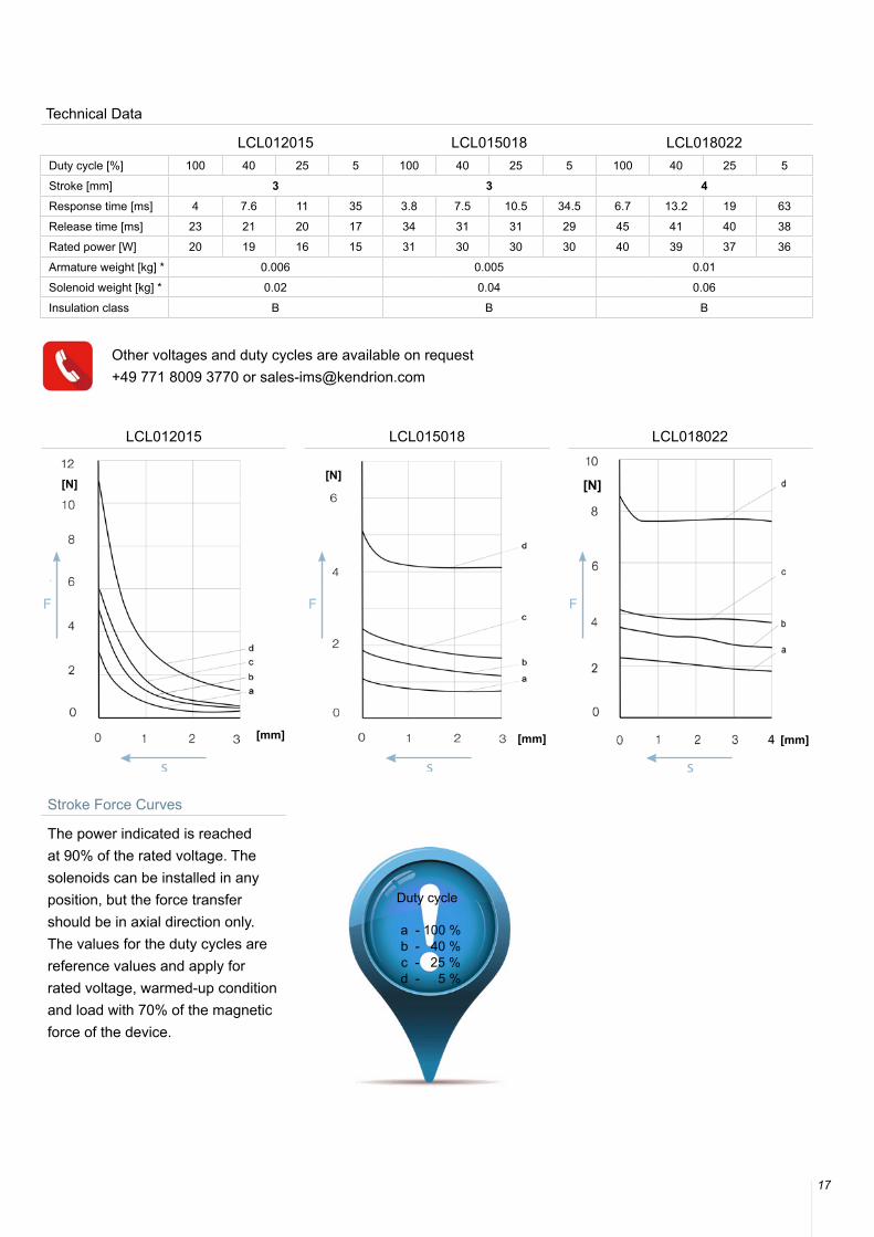
LCL012015 LCL015018 LCL018022
Stroke Force Curves
The power indicated is reached at 90% of the rated voltage. The solenoids can be installed in any position, but the force transfer should be in axial direction only. The values for the duty cycles are reference values and apply for rated voltage, warmed-up condition and load with 70% of the magnetic force of the device.
Duty cycle
a - 100 % b - 40 % c - 25 % d - 5 %
LCL012015 LCL015018 LCL018022Duty cycle [%] 100 40 25 5 100 40 25 5 100 40 25 5
Stroke [mm] 3 3 4Response time [ms] 4 7.6 11 35 3.8 7.5 10.5 34.5 6.7 13.2 19 63
Release time [ms] 23 21 20 17 34 31 31 29 45 41 40 38
Rated power [W] 20 19 16 15 31 30 30 30 40 39 37 36
Armature weight [kg] * 0.006 0.005 0.01
Solenoid weight [kg] * 0.02 0.04 0.06
Insulation class B B B
Technical Data
[N]
[mm]
s
[N]
[mm]
s
[N]
[mm]
s
Other voltages and duty cycles are available on request +49 771 8009 3770 or [email protected]
18
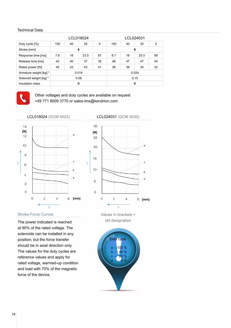
Bezeichnung LCL018024 LCL024031Duty cycle [%] 100 40 25 5 100 40 25 5
Stroke [mm] 6 6
Response time [ms] 7.6 16 23.5 87 8.7 18 25.5 89
Release time [ms] 42 40 37 35 48 47 47 45
Rated power [W] 45 43 43 41 38 36 34 32
Armature weight [kg] * 0.014 0.024
Solenoid weight [kg] * 0.08 0.15
Insulation class B B
Technical Data
Other voltages and duty cycles are available on request +49 771 8009 3770 or [email protected]
LCL018024 (GCM 4025) LCL024031 (GCM 4030)
Stroke Force Curves
The power indicated is reached at 90% of the rated voltage. The solenoids can be installed in any position, but the force transfer should be in axial direction only. The values for the duty cycles are reference values and apply for rated voltage, warmed-up condition and load with 70% of the magnetic force of the device.
Duty cycle
a - 100 % b - 40 % c - 25 % d - 5 %
[N]
[mm]
[N]
[mm]
ss
Values in brackets = old designation
19
Excels by
Currentless holding
Energy saving
High resistance to wear
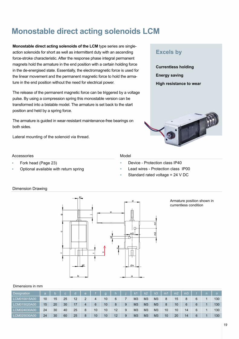
Monostable direct acting solenoids of the LCM type series are single-action solenoids for short as well as intermittent duty with an ascending force-stroke characteristic. After the response phase integral permanent magnets hold the armature in the end position with a certain holding force in the de-energised state. Essentially, the electromagnetic force is used for the linear movement and the permanent magnetic force to hold the arma-ture in the end position without the need for electrical power.
The release of the permanent magnetic force can be triggered by a voltage pulse. By using a compression spring this monostable version can be transformed into a bistable model. The armature is set back to the start position and held by a spring force.
The armature is guided in wear-resistant maintenance-free bearings on both sides.
Lateral mounting of the solenoid via thread.
Dimensions in mm
Designation a b c d e f g h j k1 k2 k3 m1 m2 m3 l n o
LCM010015A00 10 15 25 12 2 4 10 6 7 M3 M3 M3 8 15 8 6 1 130
LCM015020A00 15 20 30 17 4 6 10 8 9 M3 M3 M3 8 10 6 6 1 130
LCM024030A00 24 30 40 25 8 10 10 12 9 M3 M3 M3 10 10 14 6 1 130
LCM025030A00 24 30 60 25 8 10 10 12 9 M3 M3 M3 10 20 14 6 1 130
Monostable direct acting solenoids LCM
Dimension Drawing
Accessories Model ■ Fork head (Page 23) ■ Optional available with return spring
■ Device - Protection class IP40 ■ Lead wires - Protection class IP00 ■ Standard rated voltage = 24 V DC
Armature position shown incurrentless condition
20
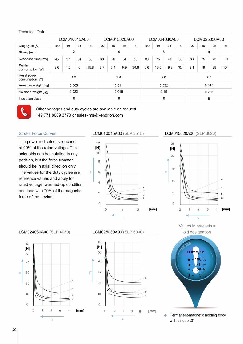
Stroke Force Curves LCM010015A00 (SLP 2515) LCM015020A00 (SLP 3020)
The power indicated is reached at 90% of the rated voltage. The solenoids can be installed in any position, but the force transfer should be in axial direction only. The values for the duty cycles are reference values and apply for rated voltage, warmed-up condition and load with 70% of the magnetic force of the device.
LCM024030A00 (SLP 4030) LCM025030A00 (SLP 6030)
LCM010015A00 LCM015020A00 LCM024030A00 LCM025030A00Duty cycle [%] 100 40 25 5 100 40 25 5 100 40 25 5 100 40 25 5
Stroke [mm] 2 4 8 8
Response time [ms] 45 37 34 30 60 56 54 50 80 75 70 60 83 75 75 70
Pull-in consumption [W] 2.6 4.5 6 15.8 3.7 7.1 9.9 30.6 6.6 13.5 19.8 70.4 9.1 19 28 104
Reset power consumption [W] 1.3 2.8 2.8 7.3
Armature weight [kg] 0.005 0.011 0.032 0.045
Solenoid weight [kg] 0.022 0.045 0.15 0.225
Insulation class E E E E
Technical Data
[N]
[mm]
s
[N]
[mm]
[N]
[mm]
s
s
[N]
[mm]
s
Other voltages and duty cycles are available on request +49 771 8009 3770 or [email protected]
Duty cycle
a - 100 % b - 40 % c - 25 % d - 5 %
Permanent-magnetic holding force with air gap „0“
Values in brackets = old designation
21
Permanent-magnetic holding force with air gap „0“
Installation Note
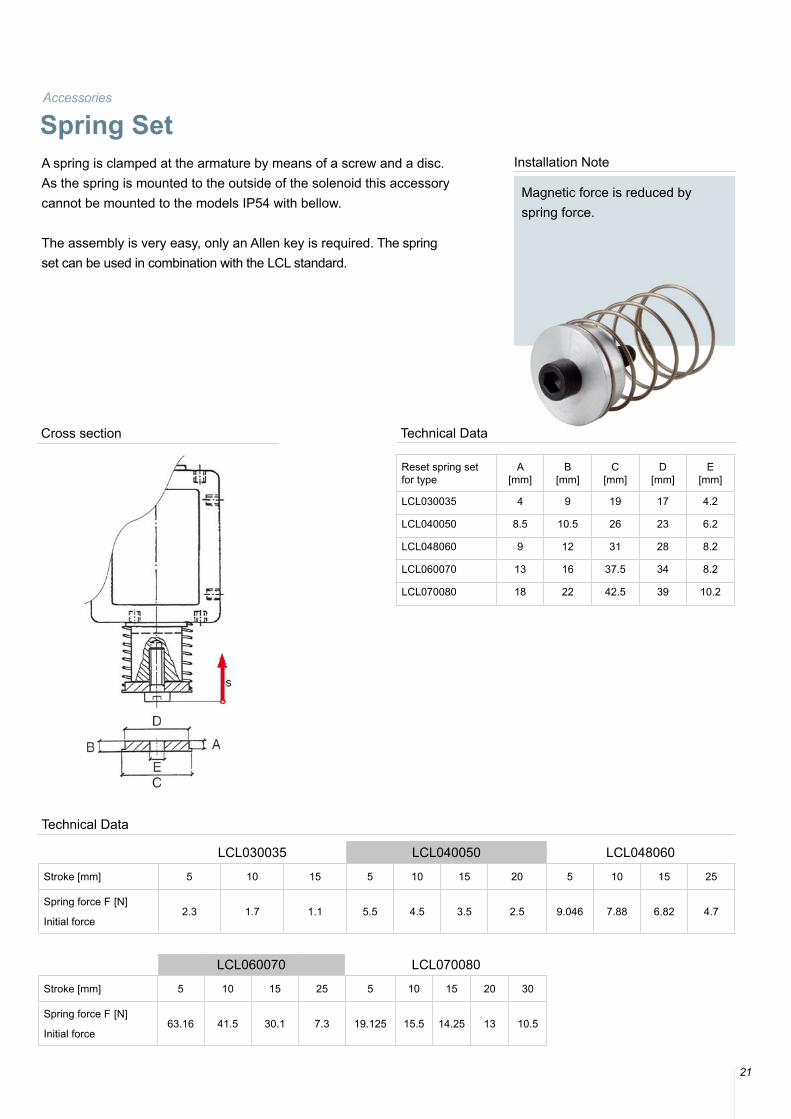
Magnetic force is reduced by spring force.
A spring is clamped at the armature by means of a screw and a disc. As the spring is mounted to the outside of the solenoid this accessory cannot be mounted to the models IP54 with bellow.
The assembly is very easy, only an Allen key is required. The spring set can be used in combination with the LCL standard.
Accessories
Spring Set
Reset spring setfor type
A[mm]
B[mm]
C[mm]
D[mm]
E[mm]
LCL030035 4 9 19 17 4.2
LCL040050 8.5 10.5 26 23 6.2
LCL048060 9 12 31 28 8.2
LCL060070 13 16 37.5 34 8.2
LCL070080 18 22 42.5 39 10.2
Technical Data
LCL030035 LCL040050 LCL048060
Stroke [mm] 5 10 15 5 10 15 20 5 10 15 25
Spring force F [N]
Initial force2.3 1.7 1.1 5.5 4.5 3.5 2.5 9.046 7.88 6.82 4.7
LCL060070 LCL070080
Stroke [mm] 5 10 15 25 5 10 15 20 30
Spring force F [N]
Initial force63.16 41.5 30.1 7.3 19.125 15.5 14.25 13 10.5
Technical Data
Cross section
22
Model
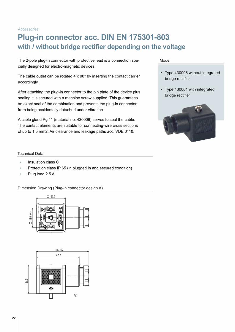
• Type 430006 without integrated bridge rectifier
• Type 430001 with integrated bridge rectifier
The 2-pole plug-in connector with protective lead is a connection spe-cially designed for electro-magnetic devices.
The cable outlet can be rotated 4 x 90° by inserting the contact carrier accordingly.
After attaching the plug-in connector to the pin plate of the device plus sealing it is secured with a machine screw supplied. This guarantees an exact seal of the combination and prevents the plug-in connector from being accidentally detached under vibration.
A cable gland Pg 11 (material no. 430006) serves to seal the cable. The contact elements are suitable for connecting-wire cross sections of up to 1.5 mm2. Air clearance and leakage paths acc. VDE 0110.
Accessories
Plug-in connector acc. DIN EN 175301-803with / without bridge rectifier depending on the voltage
Technical Data
■ Insulation class C ■ Protection class IP 65 (in plugged in and secured condition) ■ Plug load 2.5 A
Dimension Drawing (Plug-in connector design A)
23
Model
• Type 430006 without integrated bridge rectifier
• Type 430001 with integrated bridge rectifier
Installation Note
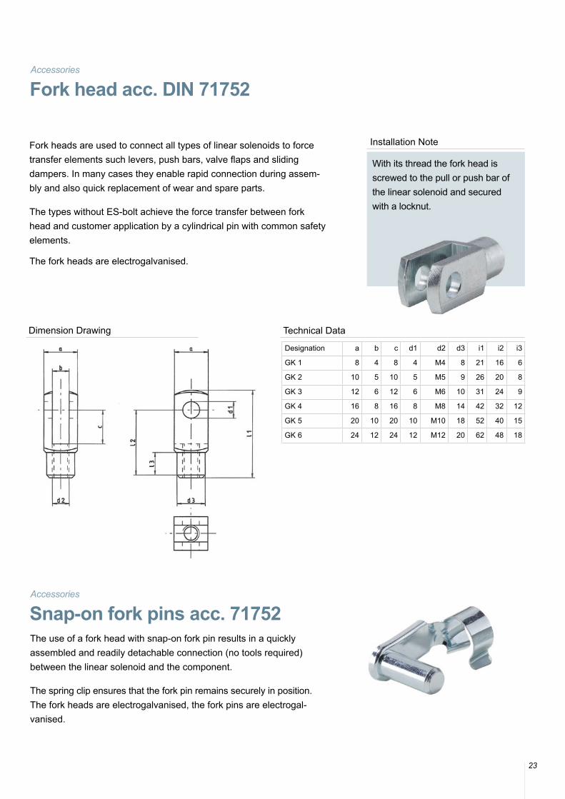
With its thread the fork head is screwed to the pull or push bar of the linear solenoid and secured with a locknut.
Fork heads are used to connect all types of linear solenoids to force transfer elements such levers, push bars, valve flaps and sliding dampers. In many cases they enable rapid connection during assem-bly and also quick replacement of wear and spare parts.
The types without ES-bolt achieve the force transfer between fork head and customer application by a cylindrical pin with common safety elements.
The fork heads are electrogalvanised.
Accessories
Fork head acc. DIN 71752
Designation a b c d1 d2 d3 i1 i2 i3
GK 1 8 4 8 4 M4 8 21 16 6
GK 2 10 5 10 5 M5 9 26 20 8
GK 3 12 6 12 6 M6 10 31 24 9
GK 4 16 8 16 8 M8 14 42 32 12
GK 5 20 10 20 10 M10 18 52 40 15
GK 6 24 12 24 12 M12 20 62 48 18
Technical Data
The use of a fork head with snap-on fork pin results in a quickly assembled and readily detachable connection (no tools required) between the linear solenoid and the component.
The spring clip ensures that the fork pin remains securely in position. The fork heads are electrogalvanised, the fork pins are electrogal-vanised.
Accessories
Snap-on fork pins acc. 71752
Dimension Drawing
Classic Line
24
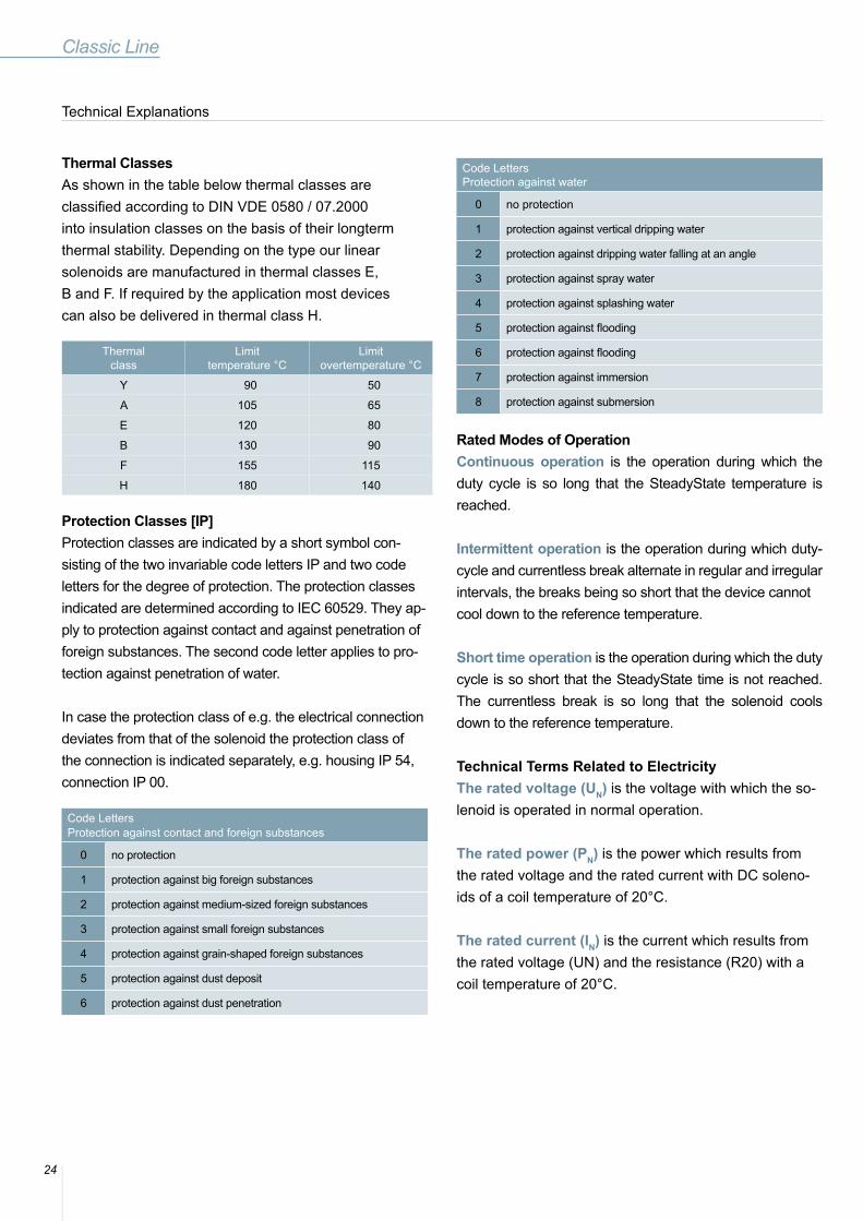
Thermal ClassesAs shown in the table below thermal classes areclassified according to DIN VDE 0580 / 07.2000into insulation classes on the basis of their longtermthermal stability. Depending on the type our linear solenoids are manufactured in thermal classes E, B and F. If required by the application most devices can also be delivered in thermal class H.
Thermalclass
Limittemperature °C
Limit overtemperature °C
Y 90 50
A 105 65
E 120 80
B 130 90
F 155 115
H 180 140
Protection Classes [IP]Protection classes are indicated by a short symbol con-sisting of the two invariable code letters IP and two code letters for the degree of protection. The protection classes indicated are determined according to IEC 60529. They ap-ply to protection against contact and against penetration offoreign substances. The second code letter applies to pro-tection against penetration of water.
In case the protection class of e.g. the electrical connection deviates from that of the solenoid the protection class of the connection is indicated separately, e.g. housing IP 54, connection IP 00.
Code LettersProtection against contact and foreign substances
0 no protection
1 protection against big foreign substances
2 protection against medium-sized foreign substances
3 protection against small foreign substances
4 protection against grain-shaped foreign substances
5 protection against dust deposit
6 protection against dust penetration
Code LettersProtection against water
0 no protection
1 protection against vertical dripping water
2 protection against dripping water falling at an angle
3 protection against spray water
4 protection against splashing water
5 protection against flooding
6 protection against flooding
7 protection against immersion
8 protection against submersion
Rated Modes of OperationContinuous operation is the operation during which the duty cycle is so long that the SteadyState temperature is reached.
Intermittent operation is the operation during which duty-cycle and currentless break alternate in regular and irregular intervals, the breaks being so short that the device cannotcool down to the reference temperature.
Short time operation is the operation during which the duty cycle is so short that the SteadyState time is not reached. The currentless break is so long that the solenoid cools down to the reference temperature.
Technical Terms Related to Electricity The rated voltage (UN) is the voltage with which the so-lenoid is operated in normal operation.
The rated power (PN) is the power which results from the rated voltage and the rated current with DC soleno-ids of a coil temperature of 20°C.
The rated current (IN) is the current which results from the rated voltage (UN) and the resistance (R20) with a coil temperature of 20°C.
Technical Explanations
25
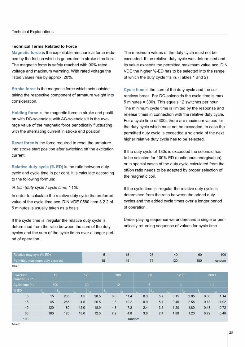
Relative duty cyle (% ED) 5 15 25 40 60 100
Permitted maximum duty cycle (s) 15 45 75 120 180 randomTable 1
Switching number (S / h)
12 120 300 600 1200 3000
Cycle time (s) 300 30 12 6 3 1.2
% ED ton toff ton toff ton toff ton toff ton toff ton toff
5 15 285 1.5 28.5 0.6 11.4 0.3 5.7 0.15 2.85 0.06 1.14
15 45 255 4.5 25.5 1.8 10.2 0.9 5.1 0.45 2.55 0.18 1.02
40 120 180 12.0 18.0 4.8 7.2 2.4 3.6 1.20 1.80 0.48 0.72
60 180 120 18.0 12.0 7.2 4.8 3.6 2.4 1.80 1.20 0.72 0.48
100 randomTable 2
Technical Terms Related to ForceMagnetic force is the exploitable mechanical force redu-ced by the friction which is generated in stroke direction.The magnetic force is safely reached with 90% rated voltage and maximum warming. With rated voltage the listed values rise by approx. 20%.
Stroke force is the magnetic force which acts outside taking the respective component of armature weight into consideration.
Holding force is the magnetic force in stroke end positi-on with DC-solenoids; with AC-solenoids it is the ave-rage value of the magnetic force periodically fluctuating with the alternating current in stroke end position.
Reset force is the force required to reset the armature into stroke start position after switching off the excitation current.
Relative duty cycle (% ED) is the ratio between duty cycle and cycle time in per cent. It is calculate according to the following formula:
% ED=(duty cycle / cycle time) * 100
In order to calculate the relative duty cycle the preferred value of the cycle time acc. DIN VDE 0580 item 3.2.2 of 5 minutes is usually taken as a basis.
If the cycle time is irregular the relative duty cycle is determined from the ratio between the sum of the duty cycles and the sum of the cycle times over a longer peri-od of operation.
The maximum values of the duty cycle must not be exceeded. If the relative duty cycle was determined and its value exceeds the permitted maximum value acc. DIN VDE the higher %-ED has to be selected into the range of which the duty cycle fits in. (Tables 1 and 2)
Cycle time is the sum of the duty cycle and the cur-rentless break. For DC-solenoids the cycle time is max. 5 minutes = 300s. This equals 12 switches per hour. The minimum cycle time is limited by the response and release times in connection with the relative duty cycle. For a cycle time of 300s there are maximum values for the duty cycle which must not be exceeded. In case the permitted duty cycle is exceeded a solenoid of the next higher relative duty cycle has to be selected.
If the duty cycle of 180s is exceeded the solenoid has to be selected for 100% ED (continuous energisation) or in special cases of the duty cycle calculated from the off/on ratio needs to be adapted by proper selection of the magnetic coil.
If the cycle time is irregular the relative duty cycle is determined from the ratio between the added duty cycles and the added cycle times over a longer period of operation.
Under playing sequence we understand a single or peri-odically returning sequence of values for cycle time.
Technical Explanations
26
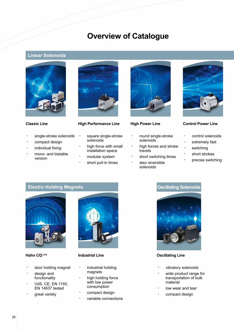
Overview of Catalogue
Classic Line
■ single-stroke solenoids ■ compact design ■ individual fixing ■ mono- and bistable
version
Hahn CQ Line
■ door holding magnet ■ design and
functionality ■ VdS, CE, EN 1155,
EN 14637 tested ■ great variety
High Performance Line
■ square single-stroke solenoids
■ high force with small installation space
■ modular system ■ short pull-in times
Industrial Line
■ industrial holding magnets
■ high holding force with low power consumption
■ compact design ■ variable connections
High Power Line
■ round single-stroke solenoids
■ high forces and stroke travels
■ short switching times ■ also reversible
solenoids
Control Power Line
■ control solenoids ■ extremely fast ■ switching ■ short strokes ■ precise switching
Oscillating Line
■ vibratory solenoids ■ wide product range for
transportation of bulk material
■ low wear and tear ■ compact design
Linear Solenoids
Electro Holding Magnets Oscillating Solenoids
2727
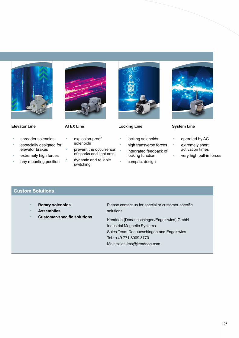
Elevator Line
■ spreader solenoids ■ especially designed for
elevator brakes ■ extremely high forces ■ any mounting position
ATEX Line
■ explosion-proof solenoids
■ prevent the occurrence of sparks and light arcs
■ dynamic and reliable switching
Locking Line
■ locking solenoids ■ high transverse forces ■ integrated feedback of
locking function ■ compact design
System Line
■ operated by AC ■ extremely short
activation times ■ very high pull-in forces
■ Rotary solenoids ■ Assemblies ■ Customer-specific solutions
Please contact us for special or customer-specific solutions.
Kendrion (Donaueschingen/Engelswies) GmbHIndustrial Magnetic SystemsSales Team Donaueschingen and Engelswies Tel.: +49 771 8009 3770Mail: [email protected]
Linear Solenoids
Custom Solutions
© KENDRION 16.07.2018
Germany : HeadquartersKendrion (Donaueschingen/Engelswies) GmbHAugust-Fischbach-Straße 178166 DonaueschingenTelefon: +49 771 8009 0Telefax: +49 771 8009 [email protected]
Germany: HeadquartersKendrion (Donaueschingen/Engelswies) GmbHHauptstraße 672514 Inzigkofen-EngelswiesTelefon: +49 7575 208 0Telefax: +49 7575 208 [email protected]
For futher contacts please refer to www.kendrion.com
If you do not find what you are looking for, please feel free to contact us!We will find the best solution for you.