CLAMP-ON GROUND RESISTANCE TESTER - Home - · PDF file · 2015-05-25IV. LIQUID...
19
CLAMP-ON GROUND RESISTANCE TESTER DET10C/DET20C USERS MANUAL
-
Upload
vuongquynh -
Category
Documents
-
view
217 -
download
3
Transcript of CLAMP-ON GROUND RESISTANCE TESTER - Home - · PDF file · 2015-05-25IV. LIQUID...

CLAMP-ON GROUND RESISTANCE TESTER
DET10C/DET20C
USERS MANUAL

EN 61010-2-032 CAT III 300V, CAT II 600V Pollution Degree 2
Definition of Symbols:
Caution: Refer to Accompanying Documents
Caution: Risk of Electric Shock
Double Insulation

Table of Contents
I. WARNING....................................................................................1
II. FEATURES DESCRIPTION .......................................................1
III. CONTROLS DESCRIPTION .....................................................2
IV. LIQUID CRYSTAL DISPLAY .....................................................3
V. OPERATING INSTRUCTIONS...................................................4
5-1. Ground Resistance Measurement ..........................................4 5-2. High and Low Alarm ( ) .....................................................5 5-3. Ground/Leakage Current Measurement .................................7 5-4. Setting the Sampling Interval ..................................................7 5-5. Data Logging...........................................................................8 5-6. Downloading Data to a PC (DET20C only) .............................8 5-7. Format of Down Loaded Data (DET20C only) ........................9 5-8. Reading the Data Stored in Memory .......................................9 5-9. Clearing the Data Memory ....................................................10 5-10. Enable RS-232C output (DET20C only) .............................10 5-11. Installation of Megger Download Manager Software...........11 5-12. Description of Megger Download Manager Software..........11
VI. PRINCIPLE OF OPERATION .................................................12
VII. ELECTRICAL SPECIFICATION ............................................14
VIII. GENERAL SPECIFICATIONS ..............................................15
IX. BATTERY REPLACEMENT....................................................16

I. WARNING 1. Use of rubber gloves is good safety practice even if the equipment is
properly operated and grounded. 2. Safety is the responsibility of the operator. 3. Use extreme caution when using the instrument around energised
electrical equipment. 4. Do not attempt to use the ground tester to twist or pry the ground
electrode or ground wire away from the equipment being grounded. 5. All metal objects or wires connected to the electrical system should
be assumed to be lethal until tested, the grounding system is no exception.
II. FEATURES DESCRIPTION
The clamp-on ground resistance tester enables the user to measure the ground resistance of a ground rod without the use of auxiliary ground rods. The clamp-on ground resistance tester is used in multi-grounded systems without disconnecting the ground under test.
1

III. CONTROLS DESCRIPTION
1
2
3
4
5 6
9
8
7
1. Jaw Assembly: Encircle electrode or ground rod. No air gap is allowed between the two jaw halves.
2. Hold Button: Maintains last measurement on display 3. Rotary Switch: Power on and function selection.
4. LCD panel 5. “ REC ” button: Function dependant on mode. Starts either
data logging, single measurement recording, or data download to PC. Also used to increment a value in conjunction with FUNC button.
6. “ FUNC “button: Press to select “HI” (high alarm), “LO” (low alarm), “SEC” (recording interval), “dL” (Data down load), “no” (Read Data) or “232” (RS-232C)
7. Jaw opening lever 8. Battery cover 9. RS-232C interface connection point (DET20C only)
2

IV. LIQUID CRYSTAL DISPLAY
AP
1. Function Display current selected function or current record number.
2. Digits Display value from 0 to 9999 with decimal point.
3. Ohm Indicates resistance mode and alarm functions.
4. mA Indicates ground leakage current mode in mA or A
5. Indicates instrument is set at the alarm position.
6. NOISE: Indicates ground resistance tester senses noise or excessive current present in the ground electrode
7. Jaw Open Displayed if the jaws are opened during the measurement, this symbol and word OPEN will be shown in LCD.
8. Low Battery Indicates battery voltage is lower than required.
9. NO. Indicates the data record number in memory.
10. REC Indicates data logging is in progress.
11. H Indicates “HOLD” function activated
12. AP Indicates Auto Power Off activated. Deactivate by holding down the REC button then turning on unit.
3

4
V. OPERATING INSTRUCTIONS 5-1. Ground Resistance Measurement
1. Open the jaws and make sure that the mating surfaces are clean and free of dust, dirt or any foreign substance.
2. Snap the jaws a few times to ensure clean contact is made. 3. Turn the rotary switch to the Ω position to power the instrument on.
Do not clamp on to any conductor or open the jaws, as this is a self-calibration phase.
4. At power on in Ω mode, the instrument will perform a self-calibration for optimum accuracy. Users must wait for self-calibration to be complete before use. During the self-calibration phase, the LCD will show CAL7, CAL6, CAL5, CAL4, CAL 3, CAL2, and CAL1.
5. When the ground tester is ready, a beep will be heard. 6. Place the clamp around the electrode or ground rod to be
measured. Operate the jaws a few times for better accuracy. 7. Read the value of Rg (ground resistance) from LCD.
Note: For better measurement: 1. Operate the jaws a few times before powering on to clear mating surfaces. 2. Do not clamp on to any conductor during power up (point 3 above). 3. Operate the jaws a few times after clamping around the ground electrode.
Note: If self-calibration does not complete (The instrument will continue the process until a successful self-calibration is achieved): 1. Check the jaw mating surfaces. If there is any dirt, dust, or any foreign substance, clean the surfaces. 2. Ensure the jaws are not open during self-calibration.
Note: Noise present in the electrode or ground rod. If there is excessive current or over 30V noise in the ground rod, a symbol of “NOISE” will be shown in LCD. Under these conditions, the reading is no longer accurate. We recommend the current flow is measured before a resistance reading is taken.
Note: If jaws are opened during a measurement, a symbol of “OPEN” will be displayed on the LCD.

5-2. High and Low Alarm ( )
1. Set the rotary switch to the position. 2. Press the FUNC button to select “HI“ or “LO” alarm. The present
value of High or Low alarm will be shown in the lower row of LCD.
3. Press the button to increment the value by 1 ohm. If the button is held down, the rate of increment accelerates. The value can be set from 0 ohm to 1550 ohm and then OL. The value will roll over to 1(HI) or 0 (LO) if the set value in incremented past OL.
4. Once the value is set, press the FUNC button several times until the upper row LCD does not show any letters.
5. When the rotary switch is set at the position the instrument will compare the measured value with the high and low values. If the measurement is higher than the HI value, the unit will beep and show “HI --" in the upper row of LCD. If the current measurement is lower than the LO value, the unit will beep and show “LO-- “ in the upper row of LCD.
5

6
NOTE: If the HI value is set at OL, or the LO value is set at 0, the ALARM function is disabled. The HI or LO value can be disabled individually
NOTE: The HI value cannot be lower than the LO value. Similarly the LO value cannot be higher than the HI value. HI value will be adjusted to LO value plus 1 if roll-over occurs. The maximum value of LO value is HI value minus 1.
NOTE: If data logging is in progress, the beeper will be disabled to save battery power. However, the LCD displays the warning letters of “HI—“ or “LO—“ if an alarm condition occurs
NOTE: The values for the high and low alarm are stored in the memory. The values will be active when the unit is powered on and alarm mode selected.

5-3. Ground/Leakage Current Measurement 1. Set the rotary switch to the mA or A position.
2. Place the clamp around the electrode or ground rod to be measured.
3. Read the value of leakage current displayed on the LCD.
5-4. Setting the Sampling Interval
1. Press the FUNC button until the letters “SEC” are shown on the upper row of LCD.
2. The unit shows the current sampling interval in seconds.
3. Press the button to increment the value by 1 second. If the button is held down, the rate of increment accelerates. The value can be set from 0 to 255 seconds. The set value will roll over to 0 when the value of maximum 255 seconds is reached.
4. Press the FUNC button several times until the upper row LCD does not show any symbols.
NOTE: The sampling interval is used for data logging and RS-232C output timing.
7

5-5. Data Logging The unit will start data logging if the “REC ” button is pressed, and the symbol “REC” will be shown on the LCD. Data will be recorded at the specified sampling interval. Data logging will be stopped if the memory is full, or the unit detects a low battery condition, or the “REC ” button is pressed again.
NOTE: With sampling time greater than zero the Auto Power Off feature is disabled in this mode
NOTE: If the sampling interval is set at 0 seconds, one set of data is recorded. To record the next set of data, press the “REC ” button again. The record number and “REC” symbol is displayed for approximately 1 second. 5-6. Downloading Data to a PC (ASCII format)(DET20C only)
1. Connect the RS-232C cable to the unit and a PC. 2. Run any application software which can accept ASCII data. 3. Press the FUNC button until the symbol “dL” is shown in the upper
row on the LCD. The number of records in the memory is shown in the lower row on the LCD.
4. Press the “REC ” button to down load all the data stored in the memory. The symbol “ -- “ is shown next to the symbol “dL” when data is transferring to PC in ASCII format.
5. The process of down loading can only be halted by turning the instrument off.
6. To exit this function, press the FUNC button several times until the upper row LCD shows no symbols.
NOTE: The unit first sends the sampling time, then the rest of the data stored in memory is sent to the PC.
8

9
5-7. Format of Down Loaded Data (DET20C only) The data is down loaded to the PC in ASCII format. In addition to data readings information includes status of jaws open, noise, HI alarm, LO alarm, and low battery. Below is a list of abbreviations for each condition and an example of data down loaded to the PC:
List of abbreviations: Abbreviation Abbreviation Abbreviation
OPEN Jaws open NS Noise HI Hi alarm
LO Low alarm HD Data hold LB Battery low Example of down loaded data: 0001 (sampling time) 10.00 ohm 10.02 ohm 5.200 ohm LO 1.000 ohm NS 1.500 mA 9.00 A NOTE: Each record is ended by <CR> and <LF>. The corresponding ASCII codes for <CR> and <LF> are 13 and 10. 5-8. Reading the Data Stored in Memory
This function allows users to read the data stored directly from the instrument display.
1. Press the FUNC button until the symbol “NO.” is shown on the LCD. The current record number is shown on the upper row of the LCD, the data is shown in the lower row of LCD.
2. Press the button to read the next data record.
3. Holding down the "” button accelerates the rate of increment. The record number will roll over to 1 when the last record is reached.

5-9. Clearing the Data Memory With the instrument powered down press and hold the FUNC button, then turn the power on. The symbol “CL” will be shown to indicate that memory is cleared.
5-10. Enabling the RS-232C output (DET20C only)
To save battery power, the default condition is RS-232C output disabled. To output data to a PC continuously, the RS232C can be enabled by the following procedure. 1. Press the FUNC button until the symbol “ 232” is shown on the
upper row of LCD. 2. If the RS-232C output is enabled, the symbol “-“ will follow the
symbol “232”. Press the button to toggle the status of RS-232C output.
3. To exit this function, press the FUNC button several times until the upper row on the LCD is blank.
(Disabled) (Enabled)
NOTE: The RS-232C output interval is also specified by the sampling interval. If the sampling interval is set at 0 seconds, data is outputted every 0.5 seconds.
NOTE: The RS-232C output is automatically disabled if “data logging” is in progress.
10

11
5-11. Installation of Megger Download Manager Software (DET20C)
The DET20C instrument is supplied as standard with Megger Download Manager on CD 1. Hardware and Software Requirements: The requirements are
detailed on the rear of the sleeve containing the CD
2. Installation of the Program Insert the CD. If the CD does not auto-run when inserted in the
drive, click on START, RUN, select your CD drive and run START.EXE from the CD. Follow the instructions to install the program to PC. 5-12. Description of Megger Download Manager The Megger Download Manager is a 32-bit Microsoft Windows™ application, which controls data transfer from your DET20C instrument using a specific driver. The driver may be installed from the CD or from our website www.megger.com. Download Manager receives data from the instrument and stores it in comma separated format files that can be viewed and edited with the free CSV Viewer programme included. Megger Download Manager features:
1) Single step data download from the DET20C in CSV format 2) Files managed using standard Windows™ format 3) Powerful CSV Viewer included to view, sort, edit, graph and
print downloaded data. 4) Compact driver files for quick and easy disk and internet
updates 5) Full help facility
NOTE: For operation of the Megger Download Manager refer to the help menu included in the software.
NOTE: Selecting the DET20C driver, then clicking the “Download” button on the tool bar gives the procedure for data download from the instrument

VI. PRINCIPLE OF OPERATION
Below is a simplified typical ground distribution system. The equivalent circuit is shown in Figure A. If R1, R2, R3, ... Rn are simplified to Req, then only Rg and Req are left in the circuit (refer to Figure B). If a constant voltage is applied to the circuit, the following equation is true.
VI
R Rg e= + q
Where
Req 11
, i 1, 2, ......, n
Ri
= =∑
If Rg and R1, R2, ... Rn are similar values, and n is a large number (such
as 200), then Req will be much less than Rg and approaches zero.
Rg >> Req (Req→0) Example: If Rg and R1, R2, ... Rn are all 10 Ω, respectively and n = 200. Then Req
by calculation equals
R...
.e q =+ + +
=1
110
110
110
0 05Ω
geqg R 10.050.0510RR →≈=+=+=IV
In this example, we can see that as long as the number of multiple
electrodes is large enough, the equivalent resistance is negligible with respect to the ground resistance to be measured.
12

RG 1R R2 3R RN...
FUNC
REC
HOLD
R G
1R N...RR 2 R 3
FigureB
R eq
Figure A
13

14
VII. ELECTRICAL SPECIFICATION Ground Resistance (Auto range):
Range2 Resolution Accuracy of Reading1 0.025 - 0.250 Ω 0.002 Ω ± 1.5% ± 0.05 Ω 0.250 - 9.999 Ω 0.02 Ω ± 1.5% ± 0.1 Ω 10.00 - 99.99 Ω 0.04 Ω ± 2.0% ± 0.3 Ω 100.0 - 199.9 Ω 0.4 Ω ± 3.0% ± 1.0 Ω 200.0 - 400.0 Ω 2 Ω ± 5.0% ± 5 Ω 400.0 - 600.0 Ω 5 Ω ± 10% ± 10 Ω 600.0 - 1500 Ω 20 Ω ± 20%
1Loop resistance non-inductive, external field < 50 A/m, external electrical field < 1 V/m, conductor centered in jaws. 2Resistance Measurement Frequency: 1.667KHz High and Low Alarm
Range Resolution High Alarm 0 - 1550Ω 1Ω Lo Alarm 0 - 1550Ω 1Ω
Ground/Leakage Current (Auto range, 50/60 Hz, True RMS, Crest Factor < 3.5)
Range Resolution Accuracy of Reading 0.200 - 1.000 mA 0.001 mA ± 2.0% ± 0.05 mA 1.00 - 10.00 mA 0.01 mA ± 2.0% ± 0.03 mA 10.0 - 100.0 mA 0.1 mA ± 2.0% ± 0.3 mA 100 - 1000 mA 1 mA ± 2.0% ± 3 mA
Ground/Leakage Current (50/60 Hz, True RMS, Crest Factor < 3.5)
Range Resolution Accuracy of Reading 0.20 – 35.00 A 0.01 A ± 2.0% ± 0.03 A
Accuracy of Resistance Calibration Plate: ±1% Data Logging Capacity:8180 records (DET20C), 116 records (DET10C) Data Logging Interval: 1 to 255 seconds RS-232C Output: 0.5 and 1 to 255 seconds
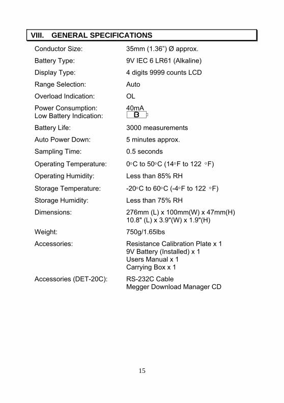
VIII. GENERAL SPECIFICATIONS
Conductor Size: 35mm (1.36”) Ø approx.
Battery Type: 9V IEC 6 LR61 (Alkaline)
Display Type: 4 digits 9999 counts LCD
Range Selection: Auto
Overload Indication: OL
Power Consumption: 40mA Low Battery Indication:
Battery Life: 3000 measurements
Auto Power Down: 5 minutes approx.
Sampling Time: 0.5 seconds
Operating Temperature: 0°C to 50°C (14°F to 122 °F)
Operating Humidity: Less than 85% RH
Storage Temperature: -20°C to 60°C (-4°F to 122 °F)
Storage Humidity: Less than 75% RH
Dimensions: 276mm (L) x 100mm(W) x 47mm(H) 10.8" (L) x 3.9"(W) x 1.9"(H)
Weight: 750g/1.65lbs
Accessories: Resistance Calibration Plate x 1 9V Battery (Installed) x 1 Users Manual x 1 Carrying Box x 1
Accessories (DET-20C): RS-232C Cable Megger Download Manager CD
15

IX. BATTERY REPLACEMENT
When the “low battery” symbol is displayed on the LCD, replace the old battery with a new battery. Remove instrument from test piece during battery change.
1. Turn the switch to the OFF position. 2. Unfasten the battery cover screw. 3. Lift and remove the battery cover. 4. Remove the old battery. 5. Install the new 9V battery. 6. Replace the battery cover and secure the screw.
16