Civil and Building BIM Coordination for Real
41
Civil and Building BIM Coordination for Real Rob Clark - Excitech Ltd CI1934-P It almost goes without saying that the structural, architectural, and civil engineering disciplines need to coordinate closely. We need to, for example, ensure that the building foundations do not clash with the utilities. Also, it is important that all parties are on the same page in regards to site coordinates to effectively coordinate and build. In this class, we build a basic site in Autodesk® AutoCAD® Civil 3D® software, then we extract the coordinates and use Autodesk® Revit® software to develop our site coordination for multiple buildings using shared coordinates. We use Autodesk® Navisworks® software to detect clashes between the Revit structural foundations and Civil 3D utilities. We produce a clash report before switching back to Revit to resolve. Finally we update the clash report with the resolution. Time permitting, we also discuss principles of using Autodesk® 360 cloud services. Learning objectives At the end of this class, you will be able to: • Detect clashes between utility information and building information • Manually manipulate site coordinates between Civil 3D, Revit, and Navisworks • Coordinate multi-structure sites effectively using the Revit and Navisworks environment • Describe technical aspects of the Building Information Modeling (BIM) workflows that are possible in Autodesk® Infrastructure Design Suite About the speaker From his original career in the Structural, Architectural and Civil profession, working in partnership with many major UK AEC firms, Rob has developed practical skills and diverse knowledge of best practice, protocols and procedures. From this experience he is further able to draw on extensive technical expertise including platform knowledge in Autodesk Revit software, AutoCAD, Civil 3D and Navisworks. As a result of his knowledge, Rob has acted as the Autodesk Revit champion for a large organisation he was previously working in partnership with. Proactive in assisting others, Rob organises UK discussion groups like BIM4Real which focus on project delivery through to assisting youngsters in the UK to develop into Architects and Engineers. Very much part of the #UKBIMCrew, Rob enjoys working and networking in the current culture of innovation in the UK construction industries. [email protected] or @clarkrob
-
Upload
duongthien -
Category
Documents
-
view
216 -
download
0
Transcript of Civil and Building BIM Coordination for Real

Civil and Building BIM Coordination for Real Rob Clark - Excitech Ltd
CI1934-P
It almost goes without saying that the structural, architectural, and civil engineering disciplines need to coordinate closely. We
need to, for example, ensure that the building foundations do not clash with the utilities. Also, it is important that all parties are
on the same page in regards to site coordinates to effectively coordinate and build. In this class, we build a basic site in
Autodesk® AutoCAD® Civil 3D® software, then we extract the coordinates and use Autodesk® Revit® software to develop our
site coordination for multiple buildings using shared coordinates. We use Autodesk® Navisworks® software to detect clashes
between the Revit structural foundations and Civil 3D utilities. We produce a clash report before switching back to Revit to
resolve. Finally we update the clash report with the resolution. Time permitting, we also discuss principles of using Autodesk®
360 cloud services.
Learning objectives At the end of this class, you will be able to:
• Detect clashes between utility information and building information
• Manually manipulate site coordinates between Civil 3D, Revit, and Navisworks
• Coordinate multi-structure sites effectively using the Revit and Navisworks environment
• Describe technical aspects of the Building Information Modeling (BIM) workflows that are possible in
Autodesk® Infrastructure Design Suite
About the speaker
From his original career in the Structural, Architectural and Civil profession, working in partnership with
many major UK AEC firms, Rob has developed practical skills and diverse knowledge of best practice,
protocols and procedures. From this experience he is further able to draw on extensive technical expertise
including platform knowledge in Autodesk Revit software, AutoCAD, Civil 3D and Navisworks. As a result
of his knowledge, Rob has acted as the Autodesk Revit champion for a large organisation he was
previously working in partnership with. Proactive in assisting others, Rob organises UK discussion groups
like BIM4Real which focus on project delivery through to assisting youngsters in the UK to develop into
Architects and Engineers. Very much part of the #UKBIMCrew, Rob enjoys working and networking in the
current culture of innovation in the UK construction industries.
[email protected] or @clarkrob

CI1934-P - Civil and Building BIM Coordination for Real by Rob Clark, Excitech
2
Contents
Learning objectives ...................................................................................................................................................... 1
About the speaker ........................................................................................................................................................ 1
Introduction to this lecture ........................................................................................................................................ 4
Why this subject? ..................................................................................................................................................... 4
The basics ................................................................................................................................................................... 4
Our project ................................................................................................................................................................. 5
Our project deliverables ......................................................................................................................................... 6
Our workflow ................................................................................................................................................................. 7
Main workflow and software summary ............................................................................................................. 7
Peripheral workflow and software summary ................................................................................................... 7
Workflow chart ......................................................................................................................................................... 8
Peripheral workflow ................................................................................................................................................ 8
Before you do anything! ............................................................................................................................................. 9
Back all your data up! .............................................................................................................................................. 9
Install the Autodesk Civil 3D object enablers ................................................................................................... 9
Ensure Revit switchback is functioning correctly .......................................................................................... 10
Ensure your Revit level and spot coordinate markers are set to shared / survey ................................. 11
Ensure you understand your units! ................................................................................................................... 12
Check your Navisworks settings ........................................................................................................................ 12
Sign up a free Autodesk account and BIM 360 Glue trail (if you don’t have full access) .................... 13
Obtain the Autodesk Point Layout trail ........................................................................................................... 13
Workflow 1 - Creation of map in Autodesk Map 3D.......................................................................................... 14
Workflow summary ............................................................................................................................................... 14
The output ............................................................................................................................................................... 14
Using GIS data to create the map ...................................................................................................................... 15
Clipping the map ................................................................................................................................................... 16
Workflows 2 - Creating the survey in AutoCAD Civil 3D .................................................................................. 20
Workflow summary ............................................................................................................................................... 20
CI1934-P - Civil and Building BIM Coordination for Real by Rob Clark, Excitech
3
The outcome ........................................................................................................................................................... 20
Generating the COGO points .............................................................................................................................. 21
Create the surface .................................................................................................................................................. 22
Extract the surface. ................................................................................................................................................ 23
Workflow 3 - Creation of a site coordination model in Autodesk Revit ....................................................... 24
Workflow summary ............................................................................................................................................... 24
The outcome. .......................................................................................................................................................... 24
Create site coordination model ......................................................................................................................... 25
Establishing the coordinate system if AutoCAD 0,0,0 is the survey point .............................................. 26
Establishing the coordinate system if AutoCAD 0,0,0 is not the survey point ...................................... 26
Linking in your Revit models and sharing the coordinate system ........................................................... 27
Installing the Civil 3D topography into Autodesk Revit .............................................................................. 30
Setting building models at the correct elevation ......................................................................................... 31
Workflow 4 - Appending and clash avoidance in Autodesk Navisworks .................................................... 33
Workflow summary ............................................................................................................................................... 33
The outcome. .......................................................................................................................................................... 33
Appending the models ........................................................................................................................................ 34
Clash avoidance exercise ..................................................................................................................................... 35
Switchback to resolve the clash ......................................................................................................................... 37
Workflow 5 - Combining the models in the Autodesk BIM 360 Cloud ........................................................ 38
Workflow summary ............................................................................................................................................... 38
The outcome ........................................................................................................................................................... 38
Creating the Autodesk BIM 360 Project ........................................................................................................... 39
Uploading a Revit model ..................................................................................................................................... 39
Creating a merged model.................................................................................................................................... 40
Summary ....................................................................................................................................................................... 41
Final tips and tricks ................................................................................................................................................ 41
Final word ................................................................................................................................................................ 41

CI1934-P - Civil and Building BIM Coordination for Real by Rob Clark, Excitech
4
Introduction to this lecture
Why this subject?
Last year I presented a well-received hands-on lab (SE2477-L) on the subject of site coordination when
Autodesk Revit is involved, and now I’m delighted to be asked back to do a lecture on the subject.
I present this subject as it comes up as an almost weekly question and as there is much conflicting and
confusing information out there on this. On top of that, I keep getting asked how to develop civil
engineering and infrastructure design in Autodesk Revit. My response is often, would you use a knife
to saw a piece of wood? Autodesk Civil 3D is the right tool for the job here. Why do I get asked this?
Aside from trying to understandably avoid learning two pieces of software and as a side note, the
efficiency gains of using the right tools for the job hugely out weigh the learning and software costs, it
is the coordination of this information were the problem sits. People often have issues coordinating
the topography of their site and site utilities produced in AutoCAD based software and with building
information produced in Revit based software. This is as these two platforms do not share the same
system of producing coordinates, although both are more than capable of working with large
coordinated sites.
So what you can’t do is work in Revit as you would in AutoCAD, or vice versa. Indeed, it is in trying to
do this that a lot people fail with this exercise. What’s needed is a well understood way of
coordinating this information and the good news is that is what this lecture and associated paper is
about.
As a consultant, my role is often to give advice on not only on the various ways of doing things, but
the best. The workflow that I present in here is not the only way to achieve site coordination between
AutoCAD based products and Revit based products, however I believe it is the best. Why do I believe
it is the best? It’s visual. You don’t need to grab a pen and paper and work out angles between the
direction of the True North vs your building pads main façade, which if you have ever tried to do and
ended up utterly befuddling yourself, you have my every sympathy.
The basics
You need a map of your site in a CAD format such as DWG or DGN. This should have either a World
Coordinate System (WCS) set for a known coordinate grid, or alternatively have a known coordinate
on site. You need to know where north is, hopefully on a map or a survey this is simply the upward
direction. You need to have an idea where your building or buildings are located.
You need a Revit model, or multiple Revit models for multi-structure sites. It doesn’t matter if the Revit
model has already being developed. Site coordination in Revit, while it probably should for other
reasons, does not from a software perspective need to happen at project initiation. You don’t need to
model your building in the correct position to 0,0,0. Indeed, because of the fact Revit data has to exist
20 miles from the center of the file, it’s likely you can’t do this anyway - but don’t worry, that’s not a
problem. You certainly don’t need to model in the correct orientation to true North, which if you did
would mean you modeling at angles in Revit without the AutoCAD system of setting a UCS. Finally, at
no point do you need to move a model risking breaking parametric joins within the building.

CI1934-P - Civil and Building BIM Coordination for Real by Rob Clark, Excitech
5
Our project
It’s helpful, even in this learning environment to put ourselves in a real world design scenario. So this
lecture is set out as if delivering a project.
We are designing several buildings on a site. One of the buildings is an existing office building that
has had a point cloud captured for it. The other buildings are new builds and relatively simple in
structure.
We are putting a simple extension on the back of the office building and as such we have produced a
Autodesk Revit model from the point cloud survey, and have used phasing to draw the extension, now
we need to supply staking out coordinates. Note. This lecture does not cover the creation of models from
point clouds or phasing within Revit.
For the other two buildings we have some existing site utilities running very close to our building foot
print. We need to make sure that these are not within the area of influence of the piled foundations.
On top of this we have a requirement to produce a federated model of our buildings and site. This will
be used on site for coordination including mark ups, and so needs to be available in a mobile format.
The building site is based just outside of Chester on the English and Welsh border in the UK. This
puts it’s in the Ordnance Survey National (British) Grid SJ.
To ensure this handout is useful on all projects, the workflows presented in this paper do not mention
the project specifically, but it was used in the lecture at AU 2013.

CI1934-P - Civil and Building BIM Coordination for Real by Rob Clark, Excitech
6
Our project deliverables
Based on the above project requirements, we need among our traditional documentation
deliverables,
1. Staking out coordinates for the extension 2. Clash reports for the foundations vs. utilities 3. Accessible federated models
For this we need to produce
1. A map to of the relevant area (grid SJ) 2. The topography of the site 3. Modeled site utilities 4. A site coordination model in Revit 5. Revit building models 6. Federated models 7. Clash reports 8. A CSV and DXF listing the coordinates of the building extension elements 9. Accessibility to the data on a mobile platform
This lecture benefits from the following having already being created;
1. Surveyed COGO points 2. Site utilities modeled in Civil 3D 3. Revit building models

CI1934-P - Civil and Building BIM Coordination for Real by Rob Clark, Excitech
7
Our workflow
Main workflow and software summary
• Autodesk Map 3D - Creation of map
o Creation of SJ Map from GIS data
o Marking out building footprints
o Site coordinate acquisition
• Autodesk Civil 3D - Creation of survey
o Import of surveyed COGO points
o Creation of topographical surface
o Import of modeled site utilities
• Autodesk Revit - Creation of site coordination model
o Import map (as generated above)
o Shared coordinate system management in Revit environment
o Creation of topography in Revit environment
o Full 3D site model including building data
• Autodesk Navisworks Simulate or Manage - Federation of model
o Appending all models together on site coordinate grid
• Autodesk Navisworks Manage (not Simulate) - Clash avoidance
o Clash detection between Revit foundations and Civil 3D utilities
o Clash resolution via Switchback
Peripheral workflow and software summary
• Autodesk Point Layout - Field staking out points
o CSV and DXF export of point for field equipment
• Autodesk BIM 360 Glue - Cloud based model
o Federation of model in cloud to make available online
o Marking up
o Clash avoidance work
• Autodesk BIM 360 Glue for iPad - Mobile viewing of model
o Mobile viewing and marking up

CI1934-P - Civil and Building BIM Coordination for Real by Rob Clark, Excitech
8
Workflow chart
Peripheral workflow
CI1934-P - Civil and Building BIM Coordination for Real by Rob Clark, Excitech
9
Before you do anything!
Back all your data up!
It really is vital here. A lot of these workflows involve using tools that can only be used once and then
the change is permanent. These changes include moving coordinate systems, potentially in maps!
I tend to zip up all of my data as a copy before starting. That way, if there are any errors I can simply
unzip these files and overwrite the issue files.
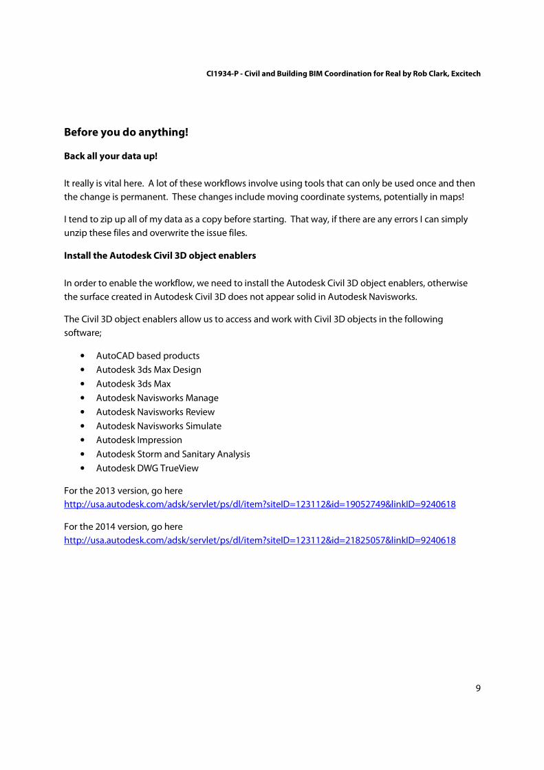
Install the Autodesk Civil 3D object enablers
In order to enable the workflow, we need to install the Autodesk Civil 3D object enablers, otherwise
the surface created in Autodesk Civil 3D does not appear solid in Autodesk Navisworks.
The Civil 3D object enablers allow us to access and work with Civil 3D objects in the following
software;
• AutoCAD based products
• Autodesk 3ds Max Design
• Autodesk 3ds Max
• Autodesk Navisworks Manage
• Autodesk Navisworks Review
• Autodesk Navisworks Simulate
• Autodesk Impression
• Autodesk Storm and Sanitary Analysis
• Autodesk DWG TrueView
For the 2013 version, go here
http://usa.autodesk.com/adsk/servlet/ps/dl/item?siteID=123112&id=19052749&linkID=9240618
For the 2014 version, go here
http://usa.autodesk.com/adsk/servlet/ps/dl/item?siteID=123112&id=21825057&linkID=9240618

CI1934-P - Civil and Building BIM Coordination for Real by Rob Clark, Excitech
10
Ensure Revit switchback is functioning correctly
SwitchBack enables you to select an object in a model in Autodesk Navisworks, and then locate and
zoom into the same object in Revit and Civil 3D.
In order for the Navisworks Switchback facility to work you need to install the Navisworks Exporters.
These should already be installed if you installed the Autodesk Building or Infrastructure Design Suites
or have installed Navisworks after Autodesk Revit and AutoCAD Civil 3D. However if you installed
Autodesk Revit or AutoCAD Civil 3D after Autodesk Navisworks they will be missing. It is also possible
to skip this part of the installation when installing Autodesk Navisworks or one of the suites.
To check installation, run the command NWCOUT in AutoCAD Civil 3D, if unknown the exporter is not
installed.
In Autodesk Revit, go to the Add-In’s tab, Extensions pull down, if the Navisworks and Navisworks
Switchback options are not available the exporter is not present.
To install the Autodesk Navisworks Exporters;
1. You need to have Autodesk Navisworks installed.
2. Close all Autodesk software.
3. Go to Windows button > Control Panel > Programs > Programs and Features
4. Select Double-click Autodesk Navisworks 32 or 64 bit Exporter Plug-ins.
NOTE: Ensure you select the Exporter Plug-ins and not the Language Packs.
5. Click Add or Remove Features.
6. Select Revit and AutoCAD if it is not already selected.
NOTE: If the Revit or AutoCAD option is not available then click Browse to locate it in your
directory.
7. Follow the update process, clicking Yes on any further dialog boxes.
8. Restart Revit and AutoCAD Civil 3D.
9. To check installation, run the command NWCOUT in AutoCAD Civil 3D, if successful the
Exporter is installed. In Autodesk Revit, go to the Add-In’s tab, Extensions pull down, if the
Navisworks and Navisworks Switchback options are present then the Exporter is installed.
Switchback should now work for both applications.
CI1934-P - Civil and Building BIM Coordination for Real by Rob Clark, Excitech
11
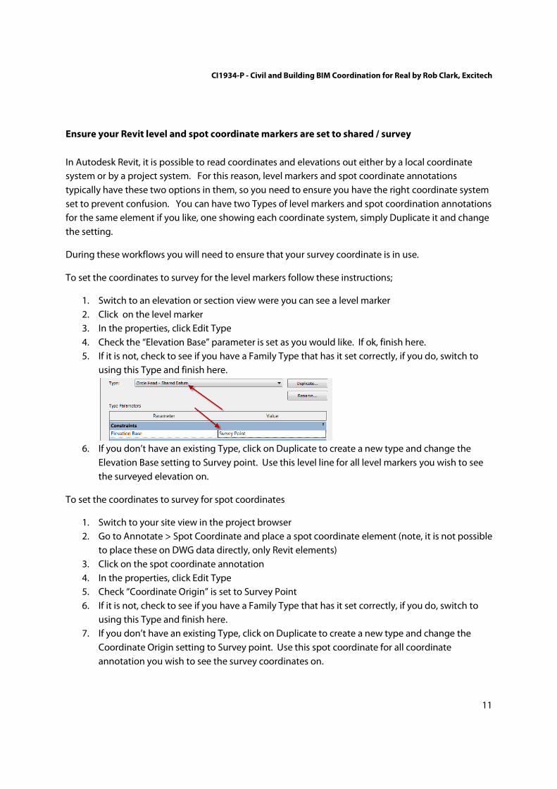
Ensure your Revit level and spot coordinate markers are set to shared / survey
In Autodesk Revit, it is possible to read coordinates and elevations out either by a local coordinate
system or by a project system. For this reason, level markers and spot coordinate annotations
typically have these two options in them, so you need to ensure you have the right coordinate system
set to prevent confusion. You can have two Types of level markers and spot coordination annotations
for the same element if you like, one showing each coordinate system, simply Duplicate it and change
the setting.
During these workflows you will need to ensure that your survey coordinate is in use.
To set the coordinates to survey for the level markers follow these instructions;
1. Switch to an elevation or section view were you can see a level marker
2. Click on the level marker
3. In the properties, click Edit Type
4. Check the “Elevation Base” parameter is set as you would like. If ok, finish here.
5. If it is not, check to see if you have a Family Type that has it set correctly, if you do, switch to
using this Type and finish here.
6. If you don’t have an existing Type, click on Duplicate to create a new type and change the
Elevation Base setting to Survey point. Use this level line for all level markers you wish to see
the surveyed elevation on.
To set the coordinates to survey for spot coordinates
1. Switch to your site view in the project browser
2. Go to Annotate > Spot Coordinate and place a spot coordinate element (note, it is not possible
to place these on DWG data directly, only Revit elements)
3. Click on the spot coordinate annotation
4. In the properties, click Edit Type
5. Check “Coordinate Origin” is set to Survey Point
6. If it is not, check to see if you have a Family Type that has it set correctly, if you do, switch to
using this Type and finish here.
7. If you don’t have an existing Type, click on Duplicate to create a new type and change the
Coordinate Origin setting to Survey point. Use this spot coordinate for all coordinate
annotation you wish to see the survey coordinates on.
CI1934-P - Civil and Building BIM Coordination for Real by Rob Clark, Excitech
12
Ensure you understand your units!
In the UK, surveys and maps are usually drawn in metres. Building design information regardless of it
being in traditional CAD drawing or in models tends to be created in millimetres. This means for
example that if you bring your map into Revit, were the model is in millimetres that you must tell the
Revit software to use meters for the import. Equally, when you specify coordinates in Revit that were
taken in meters, you need to remember to move the decimal place accordingly to input them in
millimetres. Other locales are likely to have similar unit considerations. Therefore in order to get
information to combine / federate correctly it is absolutely essential that you have checked the units.
Things to check
In Revit
To check the model units go to Manage > Project Units and check the Length units.
When linking CAD ensure that the Import Units is set to the units in the CAD drawing. Revit will then
import it at the correct scale.
In AutoCAD
On the command line, type “Units” and press enter. This will sometimes be set to “Unitless”, which
simply means that 1 = whatever unit it was drawn in. If this is the case, you may have to speak to the
surveyor or consult the documentation that comes with your map file in order to understand the unit.
Or take a few test measurements and work it out logically. The command “DIST” is the easiest way to
do this.
In Navisworks
When appending drawings and models, you can often change the units which will likely make the
difference between a successful import or not. Check the File Readers for the formats you are
bringing in. You can do this by going to the Application Button > Options > File Readers > your
format. For example, DWG has a “Default Decimal Units” setting.
Check your Navisworks settings
As well as the units settings mentioned previously. Other settings may make a difference during
import and you should check everything under Options however some key ones are;
1. Revit File Reader : Coordinates. Make sure this is set to shared to use the survey coordinates
2. Revit File Reader : Convert Element Properties. Make sure this is ticket to get the Revit
properties needed to create search sets for clash avoidance etc.
3. DWG File Reader : DWG Loader Version : Ensure this is the version of the DWG that you are using, otherwise certain elements including Civil 3D objects may fail to show correctly.

CI1934-P - Civil and Building BIM Coordination for Real by Rob Clark, Excitech
13
Sign up a free Autodesk account and BIM 360 Glue trail (if you don’t have full access)
In order to use the Autodesk Cloud services you will need a
decent internet connection, a free Autodesk account and at
least a free 30 day trail of the Autodesk BIM 360 Glue
services.
To sign up an account go to https://360.autodesk.com and
sign up a free account.
To get your Autodesk BIM 360 Glue 30 day trail go to
https://b4.autodesk.com/freetrial/
If you have an iPad obtain the BIM 360 Glue app from the
App Store.
Obtain the Autodesk Point Layout trail
If you want to test the back to field workflows, download the Autodesk Point Layout trail from
http://www.autodesk.com/products/point-layout/free-trial
CI1934-P - Civil and Building BIM Coordination for Real by Rob Clark, Excitech
14
Workflow 1 - Creation of map in Autodesk Map 3D
Workflow summary
A coordinated digital map is required for our buildings pads to be marked out on. Simple enough.
A map can obviously be produced in lots of different ways. Some of which are;
• Have a survey commissioned in CAD format
• Buy a map, like an Ordnance Survey map in the UK
• Use GIS data like shape files to generate a layered map
• Use a combination of all of the above…
The workflow that we are using here is
1. Free vector data - Source free ESRI shape vector data from a provider. In the UK we have the
Ordnance Survey Open Data website for this. This provides the large scale datasets, for
example the UK’s British National grid SJ is 100km x 100km. The level of detail is fairly low
however it is sufficient to mark out road positions and buildings, as well as significant features
like administrative boundaries, coastal regions and locations, such as airports etc.
(http://www.ordnancesurvey.co.uk/business-and-government/products/opendata-
products.html)
2. Purchase a street level map - Source more detailed local map data that shows the width of
streets and detailed building locations, as well as perhaps important local infrastructure
considerations like services. In the UK, there are several services for this, for example
Getmapping.com.
3. Utilise Autodesk Map 3D to choose what layers of the GIS data you want, clip it and federate
it with the street level map in order to produce your site plan in CAD format.
4. Mark out building plans using simply polylines on the resulting CAD plan.
The specifics of point 3 and 4 are listed below.
The output
The output of the above is a federated DWG format site plan with the building positions marked that
we can then use to over the survey for topography editing and site utilities set out in Autodesk Civil
3D and also the coordination of the building models in Autodesk Revit.

CI1934-P - Civil and Building BIM Coordination for Real by Rob Clark, Excitech
15
Using GIS data to create the map
This workflow assumes you have the GIS shape file data already available. See step 1 in main
workflow.
1. Open AutoCAD Map or Civil 3D.
2. Use the Planning and Analysis workspace
3. Ensure the Map Task Pane is on
View tab > Palettes panel > Map Task Pane
4. Connect to the data
Map Task Pane > Data > Connect to data
5. Add SHP Connection
Add SHP Connection > click on the folder icon to select the folder containing your shape
information > click on Connect
CI1934-P - Civil and Building BIM Coordination for Real by Rob Clark, Excitech
16
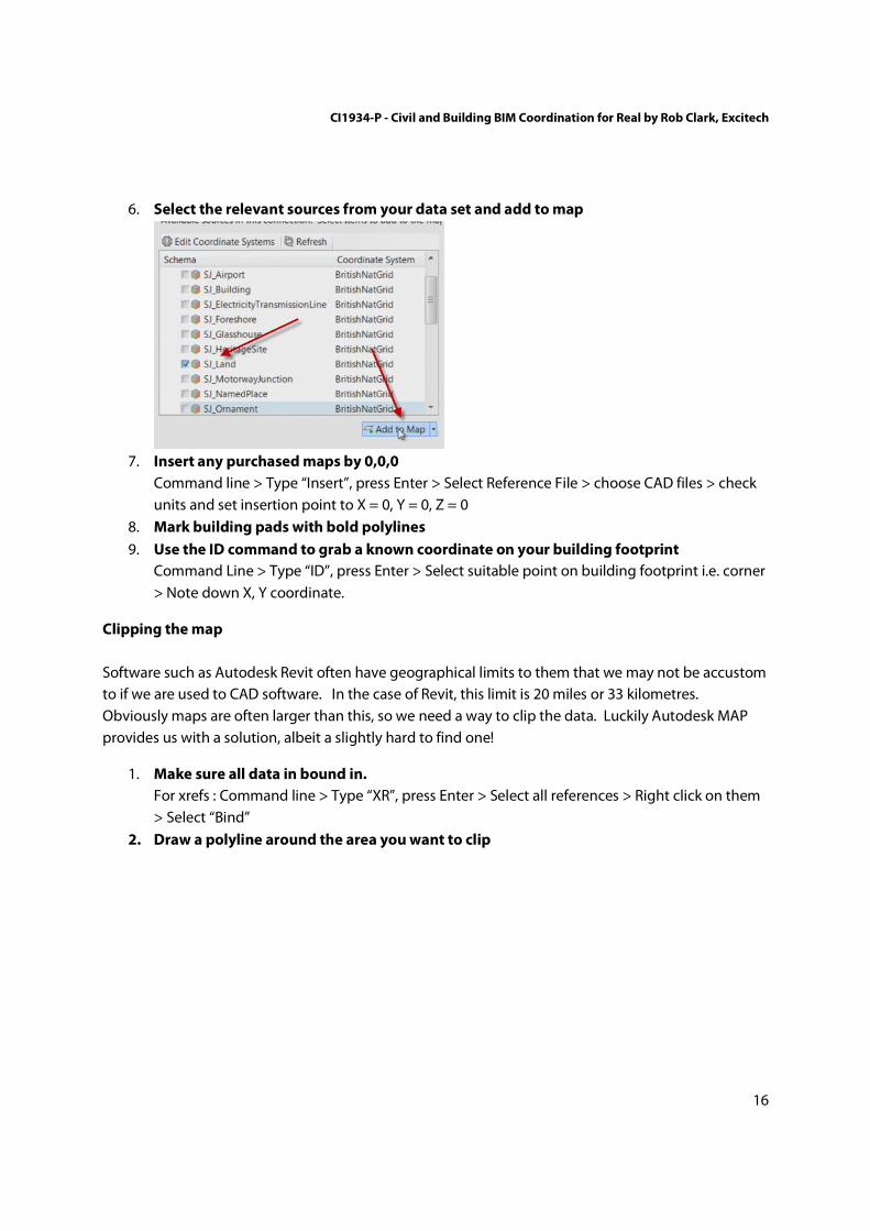
6. Select the relevant sources from your data set and add to map
7. Insert any purchased maps by 0,0,0
Command line > Type “Insert”, press Enter > Select Reference File > choose CAD files > check
units and set insertion point to X = 0, Y = 0, Z = 0
8. Mark building pads with bold polylines
9. Use the ID command to grab a known coordinate on your building footprint
Command Line > Type “ID”, press Enter > Select suitable point on building footprint i.e. corner
> Note down X, Y coordinate.
Clipping the map
Software such as Autodesk Revit often have geographical limits to them that we may not be accustom
to if we are used to CAD software. In the case of Revit, this limit is 20 miles or 33 kilometres.
Obviously maps are often larger than this, so we need a way to clip the data. Luckily Autodesk MAP
provides us with a solution, albeit a slightly hard to find one!
1. Make sure all data in bound in.
For xrefs : Command line > Type “XR”, press Enter > Select all references > Right click on them
> Select “Bind”
2. Draw a polyline around the area you want to clip

CI1934-P - Civil and Building BIM Coordination for Real by Rob Clark, Excitech
17
3. Save File As AutoCAD Drawing
Map Task Pane > Maps > Save as AutoCAD Drawing > Choose a file name and location for the
file.
4. Copy the Polyline to the clipboard using 0,0,0 origin
Left click on the polyline > Command line type “Copybase” press Enter > Command line type
“0,0,0” press Enter.
5. Create a new drawing
Command line type “QNEW” and press Enter
6. Paste the Polyline to the new drawing using 0,0,0 origin
Command line type “Pasteclip” press Enter > Command line type “0,0,0” press Enter
7. Ensure the Map Task Pane is on
View tab > Palettes panel > Map Task Pane
8. Open Windows Explorer and navigate to the drawing you saved in step 3.
Right click on the Windows Start Menu > Open Windows Explorer > Navigate to file
CI1934-P - Civil and Building BIM Coordination for Real by Rob Clark, Excitech
18
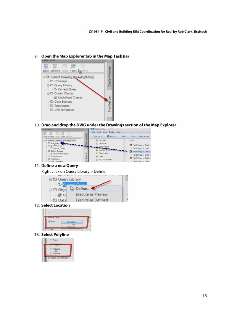
9. Open the Map Explorer tab in the Map Task Bar
10. Drag and drop the DWG under the Drawings section of the Map Explorer
11. Define a new Query
Right click on Query Library > Define
12. Select Location
13. Select Polyline

CI1934-P - Civil and Building BIM Coordination for Real by Rob Clark, Excitech
19
14. Select Define
15. Left click on the polyline
16. Press OK
17. Execute Query as Defined
Right click on Query Library > Execute as Defined
18. Save the file.
You should now have a clipped map! (I know 18 steps! If you know a better way, get in touch

CI1934-P - Civil and Building BIM Coordination for Real by Rob Clark, Excitech
20
Workflows 2 - Creating the survey in AutoCAD Civil 3D
Workflow summary
Site topology is a requirement if we want to position utilities on a site which can be clash tested
against structural foundation information. But more fundamentally, when we are coordinating our
buildings we want to illustrate them at the correct level and having the topographical surface can
assist with calculating what this level is.
Autodesk Civil 3D gives us many tools, just one of which is the taking on site captured COGO points
and translating them into contoured surfaces that can then be used to demonstrate and document
site layout in relationship to the building (s)
To do this we will
1. Utilise Site Generated Data - We have a simple text files in Autodesk Upload Format that we
will use to generate the COGO points at the correct elevation values in Civil 3D. This data may
come from a variety of sources including other text import formats which C3D supports and
field books. You can even generate a surface from a point cloud. Alternatively, for a really
boring day you could generate the points manually or utilise one of the tools in C3D to
generate points from 2D survey data
2. Apply a Surface Style - Autodesk Civil 3D allows us to take a variety of data sources including
COGO points as generate in point 1, and use them to triangulate a three dimensional surface.
We can then take this surface and apply various styles to it. For example, we can show major
and minor contours, the boundary and perhaps the triangles used to generate the surface.
3. Extract The Surface - In order that we can effectively use the surface in other platforms like
Autodesk Revit, we extract the surface to a new drawing and simply explode it.
The outcome
The above workflow would give you a information rich topographical surface within Civil 3D. This
surface can be extracted and used in other software such as Navisworks and Revit. Further, it can be
manipulated by the Civil 3D tools for grading, the inclusion of local infrastructure such as road
networks and site utilities, either existing or proposed.
CI1934-P - Civil and Building BIM Coordination for Real by Rob Clark, Excitech
21
Generating the COGO points
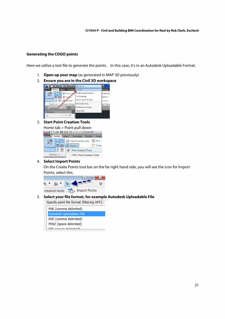
Here we utilise a text file to generate the points. In this case, it’s in an Autodesk Uploadable Format.
1. Open up your map (as generated in MAP 3D previously)
2. Ensure you are in the Civil 3D workspace
3. Start Point Creation Tools
Home tab > Point pull down
4. Select Import Points
On the Create Points tool bar on the far right hand side, you will see the icon for Import
Points, select this.
5. Select your file format, for example Autodesk Uploadable File
CI1934-P - Civil and Building BIM Coordination for Real by Rob Clark, Excitech
22
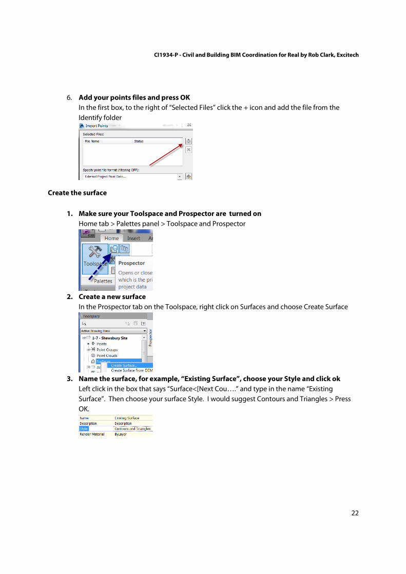
6. Add your points files and press OK
In the first box, to the right of “Selected Files” click the + icon and add the file from the
Identify folder
Create the surface
1. Make sure your Toolspace and Prospector are turned on
Home tab > Palettes panel > Toolspace and Prospector
2. Create a new surface
In the Prospector tab on the Toolspace, right click on Surfaces and choose Create Surface
3. Name the surface, for example, “Existing Surface”, choose your Style and click ok
Left click in the box that says “Surface<[Next Cou….” and type in the name “Existing
Surface”. Then choose your surface Style. I would suggest Contours and Triangles > Press
OK.

CI1934-P - Civil and Building BIM Coordination for Real by Rob Clark, Excitech
23
4. Expand the surface in the Prospector
In Toolspace, Prospector first expand the Surfaces category, and then Existing Surface by
clicking the little each of them
5. Expand Definition
6. Add the “_All Points” Point Group to your surface
Right click on Point Groups and choose Add and select _All Points and select OK. Your
surface should now be generated.
7. Save this drawing as “Survey drawing”
Extract the surface.
This is to allow us to use it in Autodesk Revit, which doesn’t work with Civil 3D object enablers.
1. Do a SaveAs on the survey drawing and call it “Surface Only”
Application button > Save As
2. Delete everything in the drawing except the surface
Tip. On command line type “Erase”, press Enter > then “All” then Enter (this selects all objects)
> then “R” (Remove) and press Enter > Select the surface and press Enter
3. Select the surface and explode it
Left click on the surface > Type on the command line, “Explode” and press enter
4. Repeat step 3 again
5. Save the drawing.
CI1934-P - Civil and Building BIM Coordination for Real by Rob Clark, Excitech
24
Workflow 3 - Creation of a site coordination model in Autodesk Revit
Workflow summary
This is a really key element to ensuring that coordination works between the Autodesk Civil 3D
platform and Autodesk Revit platform, which do not share the same method of producing site / survey
coordinates.
The site coordination model will be used in the following ways;
• Hosting the site coordinate system
• Establishing the true north position
• Establishing the shared coordinate system with the individual building models
• Creation of site topography
I would advise using this technique even if you only have one building on site. It allows you silo your
Civils data so that it doesn’t weigh down your model performance when you are editing. It also allows
you to visually position the model to north, rather than having to figure out and input the rotation
manually. Finally, were there are multiple models, it allows you to produce true site sections through
several models and allows you to install large topographical surfaces under multiple models.
The method is basically
1. Create a new Revit Architecture model and call it “Site Coordination”
2. Add your map and acquire its coordinates
3. Add your survey by shared coordinates and convert it to Revit topography
4. Insert your Revit building model(s) and publish the site coordinates to it
5. Establish your building model elevations
The outcome.
All of your Revit building models will now export in the right position to software that can utlise the
shared coordinate system such as Autodesk Navisworks and Autodesk AutoCAD.

CI1934-P - Civil and Building BIM Coordination for Real by Rob Clark, Excitech
25
Create site coordination model
1. Create a new model from the Architectural template
2. Make sure the Project Browser is open
View tab > User Interface > Project Browser ticked
3. Go to the Site view
4. Insert Your Map by Auto - Centre to Centre. Ensure you have the right units!
Insert tab > Link CAD > Left click on map. Change settings appropriate, using Auto - Centre to
Centre as the Positioning option.
NOT ORIGIN TO ORIGIN! This option would likely position the data outside of the 20 mile limit.
Make sure your Import Units are set appropriately. Review the “Before you do anything!”
section for further information.

CI1934-P - Civil and Building BIM Coordination for Real by Rob Clark, Excitech
26
Establishing the coordinate system if AutoCAD 0,0,0 is the survey point
One would hope that in a surveyed produced CAD file or in a map produced by a reputable source
that the origin of the CAD data would be the same as the coordinate datum that you wish to use. If
this is indeed, the case you can follow this set of instructions, if not, you will need to follow the second
set of instructions.
1. Acquire the coordinate system
Manage > Coordinates > Acquire Coordinates
2. Left click the DWG map in your Revit file
3. Zoom extents
You should now notice that the triangle symbol, which represents the survey point will have moved to
the same position as your CAD files 0,0,0 position. To test the coordinate system place a Spot
Coordinate (Annotate > Spot Coordinate) on a known position. Note, if you don’t get the expected
coordinate check the notes in “Before you do anything!” or if you have trouble snapping to a position,
try drawing a Detail Line (Annotate > Detail) line to get this snap point)
Establishing the coordinate system if AutoCAD 0,0,0 is not the survey point
1. Find your known coordinate in X,Y,Z format, (same as N/S, E/W).
You may need to speak to your surveyor to position this datum. It is often an existing site
feature. The coordinate given may be relative to a larger coordinate system, for example in
the UK this may be a coordinate lists to the GB036 OS coordinate system, or may simply be
0,0,0, as in the datum of the site itself. What is important is that all information that is being
coordinated shares the same datum.
2. Specify Coordinates At Point
Manage > Coordiantes > Specify Coordinates At Point
CI1934-P - Civil and Building BIM Coordination for Real by Rob Clark, Excitech
27
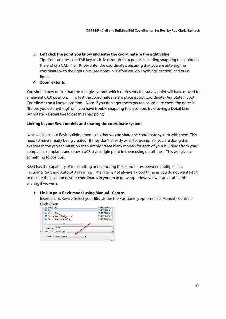
3. Left click the point you know and enter the coordinate in the right value
Tip. You can press the TAB key to circle through snap points, including snapping to a point on
the end of a CAD line. Know enter the coordinates, ensuring that you are entering the
coordinate with the right units (see notes in “Before you do anything!” section) and press
Enter.
4. Zoom extents
You should now notice that the triangle symbol, which represents the survey point will have moved to
a relevant 0,0,0 position. To test the coordinate system place a Spot Coordinate (Annotate > Spot
Coordinate) on a known position. Note, if you don’t get the expected coordinate check the notes in
“Before you do anything!” or if you have trouble snapping to a position, try drawing a Detail Line
(Annotate > Detail) line to get this snap point)
Linking in your Revit models and sharing the coordinate system
Next we link in our Revit building models so that we can share the coordinate system with them. This
need to have already being created. If they don’t already exist, for example if you are doing this
exercise in the project initiation then simply create blank models for each of your buildings from your
companies templates and draw a UCS style origin point in them using detail lines. This will give us
something to position.
Revit has the capability of transmitting or reconciling the coordinates between multiple files,
including Revit and AutoCAD drawings. The later is not always a good thing as you do not want Revit
to dictate the position of your coordinates in your map drawing. However we can disable this
sharing if we wish.
1. Link in your Revit model using Manual - Centre
Insert > Link Revit > Select your file. Under the Positioning option select Manual - Centre >
Click Open

CI1934-P - Civil and Building BIM Coordination for Real by Rob Clark, Excitech
28
2. Use your modification tools to position the model on the building pad
Tip, use the Align tool to align known parallel lines like grid lines with your building pad. Note.
Always do this with a linked file and never try to move elements in this way in a live model.
3. Select the map, and click <Not Shared> in the instance properties
Left click on the map > In the properties, the “Shared Site” parameter should be set to <Not
Shared> > Left click this
Note. If this is set to anything other than <Not Shared> then this operation has already being
done once as this is a onetime operation. You could continue by choosing the correct option
and record the new position, however to prevent any confusion, especially if this is the first
time you have done this, I would suggest returning right to the start of this Site Coordination
workflow.

CI1934-P - Civil and Building BIM Coordination for Real by Rob Clark, Excitech
29
4. Choose the first option, Publish The Shared Coordinate System
Revit will now ask you if you want to Publish (send) or Acquire (receive) the coordinate system.
This is important to get right as it is a onetime operation. The coordination model you are in
hosts the coordinates for your site and therefore you want to send them to the building model
and not receive nonsense coordinates from your building models in the site coordination
model. Therefore it’s the publish option every-time in this workflow.
5. Repeat Steps 1 to 4 for all building models on your site.
6. Save the Site Coordination Model
7. When prompted;
a. Save Position To .RVT files
b. Disable Positioning to .DWG files (!!)
It is very important that you do not allow the Revit
platform to save a new position to the DWG file. This will result in the UCS being
modified. The DWG file is your map and is master of this coordinate system, not Revit.
You can check this process has worked. Open up one of your building models and place a Spot
Coordinate (Annotate > Spot Coordinate). Ensure survey units are set in the annotation (see “Before
you do anything!” section). You should now get the correct coordinate in this model. Further, ensure
the north is set correct by setting Orientation to True North in the view properties of a plan view.

CI1934-P - Civil and Building BIM Coordination for Real by Rob Clark, Excitech
30
Installing the Civil 3D topography into Autodesk Revit
While not strictly necessary, it is possible now you have a coordinated model to install the surface you
created in workflow 2 in the Autodesk Revit model. This allows you to create visuals as well as
approximated sections of your material rich Revit models on your site.
Do note however that if you are using a platform (rather than surveyor instruction) to discover the
optimum elevation of your building, I would personally still recommend using your Civil 3D / AutoCAD
platform to extract site levels from. In my experience, the way Revit triangulates the surface leads to
subtle inaccuracies and I tend to trust the Civils platform more for this reason.
Remember, your site topography must share the same coordinate system as your map, survey and
Revit coordination model.
1. Link the Surface DWG file in by Shared Coordinates
Insert > Link CAD > Select File. Then, left click to on file > set Positioning to Auto - By Shared
Coordinates.
Note, that the origin option is not the origin of the CAD file, but the origin of the Revit file. This
origin is the centre of the Revit model.
Make sure your Import Units are set appropriately. Review the “Before you do anything!”
section for further information.
2. Ignore any messages about the UCS not being aligned.
3. Your surface should now be in the right position in CAD format.
4. Switch to 3D view
5. Start the Toposurface Command
Massing & Site > Toposurface

CI1934-P - Civil and Building BIM Coordination for Real by Rob Clark, Excitech
31
6. Select Create From Import > Select Import Instance
7. Left click on the CAD file in the 3D view
8. Select the relevant 3D layers, if you used Civil 3D, this is likely
a. C-SURFACES_Border
b. C-SURFACES_Major Contour
c. C-SURFACES_Minor Contour
9. Press OK and then the Green Tick
Your surface should now be generated. You can check elevations, noting previous comment about
Civil 3D accuracy over Revit, but using the Annotate > Spot Elevation tool
Setting building models at the correct elevation
1. Calculate your preferred building elevation using Civil 3D
For example, you may wish to match the ground floor / level 0 finish floor level with the site
topo level at your building pad position.
2. Close down the site coordination model in Revit
Application Button > Close. This is necessary as Revit cannot have a model open at the same
time as a model that has this model linked into it.
3. Open the building model in Revit.
4. Switch to an elevation view
CI1934-P - Civil and Building BIM Coordination for Real by Rob Clark, Excitech
32
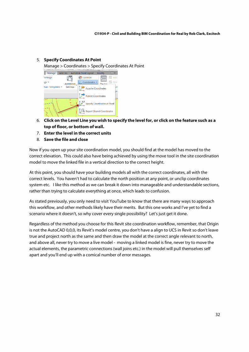
5. Specify Coordinates At Point
Manage > Coordinates > Specify Coordinates At Point
6. Click on the Level Line you wish to specify the level for, or click on the feature such as a
top of floor, or bottom of wall.
7. Enter the level in the correct units
8. Save the file and close
Now if you open up your site coordination model, you should find at the model has moved to the
correct elevation. This could also have being achieved by using the move tool in the site coordination
model to move the linked file in a vertical direction to the correct height.
At this point, you should have your building models all with the correct coordinates, all with the
correct levels. You haven’t had to calculate the north position at any point, or unclip coordinates
system etc. I like this method as we can break it down into manageable and understandable sections,
rather than trying to calculate everything at once, which leads to confusion.
As stated previously, you only need to visit YouTube to know that there are many ways to approach
this workflow, and other methods likely have their merits. But this one works and I’ve yet to find a
scenario where it doesn’t, so why cover every single possibility? Let’s just get it done.
Regardless of the method you choose for this Revit site coordination workflow, remember, that Origin
is not the AutoCAD 0,0,0, its Revit’s model centre, you don’t have a align to UCS in Revit so don’t leave
true and project north as the same and then draw the model at the correct angle relevant to north,
and above all, never try to move a live model - moving a linked model is fine, never try to move the
actual elements, the parametric connections (wall joins etc.) in the model will pull themselves self
apart and you’ll end up with a comical number of error messages.

CI1934-P - Civil and Building BIM Coordination for Real by Rob Clark, Excitech
33
Workflow 4 - Appending and clash avoidance in Autodesk Navisworks
Workflow summary
So, now the fun bit. In our map, survey and coordinated building models we have a set of data that
we can now federate together with other coordinated information to make our federated BIM.
The great news here, is now we have gone through the other 3 workflows, this is the easy bit.
The method is basically
1. Append all the models in (refer to “Before you do anything!” section first)
2. Create viewpoints to enable you to demonstrate the model to others
3. Utilize Navisworks functions such as marking up, quantification, clash avoidance and
construction sequencing. Here we utlise for clash avoidance.
4. Map and extract data from the federated BIM for asset management requirements (not
demonstrated in this paper)
5. Upload to the Autodesk BIM 360 Glue for external and mobile viewing
The outcome.
You now have a federated BIM. This model can be be utilized in a variety of ways within Navisworks
and external by others. It may be key to meeting your clients expectations
• Communication of design intent to others
• Clash avoidance checks and construction sequencing
• Quantification
• Simple visual checks. Is everything present in the model? Are there any obvious problems?
• Uploaded to Autodesk BIM 360 Glue to for closer design collaboration, for example, clash
avoidance.
• Export to free to view models that can be seen in free software including on mobile devices
• Export of a federated BIM for including in client delivery package.
• ….lots more
CI1934-P - Civil and Building BIM Coordination for Real by Rob Clark, Excitech
34
Appending the models
To gain the benefits listed here, we must first federate all of our models together. As Navisworks has
in built file readers, you don’t typically have to export your data from the platform it was generated in.
Navisworks is able to open both Autodesk Civil 3D, when object enablers are installed (see “Before you
do anything!” section), and it can also open Autodesk Revit files natively.
If you have access to them, you can of course open the models directly from their working folder. This
way all changes will be visable with Autodesk Navisworks simply by clicking on Refresh. There are
some draw backs to this method however, not least that when you are undertaking audits and clash
avoidance work, you do need to have static data otherwise you can lose track. For that reason, I tend
to recommend that you link “issued” models. Therefore I tend to set up a folder were I copied these
issued models. The file naming is important. You need to retain the file name in order to be able to
refresh the data. Therefore remove any revision lettering etc from the name and make sure you
overwrite the model when updated with a file of the same name.
It is strongly recommended that you read the “Before you do anything” section before starting
this workflow.
1. Click Append and then hold the CNTL key to multiple select files.
Home > Append. Make sure “All Files (*.*)” is selected for Files of Type > Press Open.
Depending on file sizes, this may take anything from a few seconds to several minutes. This
process speeds up greatly the second time as Navisworks has created its relevant crèche files.
2. Use the navigation tools to zoom into your model
If not already open, open the Navigation Bar by going to View > Navigation Bar, which gives
you various zoom options including zoom to region
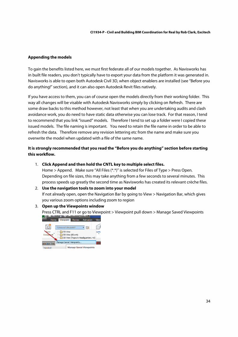
3. Open up the Viewpoints window
Press CTRL and F11 or go to Viewpoint > Viewpoint pull down > Manage Saved Viewpoints

CI1934-P - Civil and Building BIM Coordination for Real by Rob Clark, Excitech
35
4. Save any Viewpoints that you wish to return too.
Click on Viewpoint > Save Viewpoint > and assign a relevant name
This is enough to give you the ability to navigate around the model.
Clash avoidance exercise
By way of an example of what you can do with a federated model, here we use the example of
clashing site utilities created in Autodesk Civil 3D, shown on the map created in Autodesk MAP 3D,
with a structural model with foundations created in Autodesk Revit. This is a very specific example,
but illustrated here as generally as possible so that you can use the technique on other projects.
1. Open the Clash Detective
Home > Clash Detective. You may need to expand the dialog box to see the full thing. Close
additional windows, such as the Selection Sets, Selection Tree or Viewports if open
2. Add Test
In the Clash Detective window on the far right hand side you will see the Add Test option,
left click it.
3. Call the new test, “Utilities vs Foundations”
4. Choose the Select Tab
If not already open, choose the Select Tab which in between the Rules and Results tabs

CI1934-P - Civil and Building BIM Coordination for Real by Rob Clark, Excitech
36
5. In Selection A, select the B1 Revit model and B2 Revit model (file names may vary
depending on model used)
Hold down the SHIFT key and left click on the B1 model and the B2 model in the Selection A
window.
6. In Selection B, select the Utilities.dwg (file names may vary depending on model used)
Left click on the Utilities.dwg model in the Selection B window.
Note. This is the most basic form of A vs B selection in Autodesk Naviswork. You can also break down
the models using the selection tree, for example into level or alternatively find all the foul drainage
using a search set. For those serious about clash avoidance, it is worth undertaking some training on
best practice and technique. If from the UK or Europe, Excitech (www.excitech.co.uk) can provide this
training on request.
7. Select Hard Clashes to get physical clashes or Clearance to be informed of objects within
a vicinity of an object.
8. Run Test

CI1934-P - Civil and Building BIM Coordination for Real by Rob Clark, Excitech
37
9. Click on each clash to see it displayed.
Left click on each clash Navisworks should automatically turn the model into a wireframe
model other than the clashing elements. If it does not, try changing the Display Settings on
the far right hand side of the Clash Detective window. Changing the settings follows;
Switchback to resolve the clash
Now you have identified your clashes, you can run a service like Switchback. Ensure that it is enabled
first (see “Before you do anything!” section).
To switchback using Autodesk Revit
1. Open Revit and Enable Switchback (see “Before you do anything!” section)
2. Open the model that the elements that have clashed are in.
For example, open the Structural Engineering model if the clash is between the site utilities
and the structural foundations.
3. In Navisworks, right click on the element and select Switchback
4. Open Revit, if it has worked you will now be looking at the element.
5. Modify the element to resolve the clash
6. Save the mode
7. In Navisworks, Refresh the links
8. Rerun run the clash test in the Clash detective.
The clash should now be resolved.

CI1934-P - Civil and Building BIM Coordination for Real by Rob Clark, Excitech
38
Workflow 5 - Combining the models in the Autodesk BIM 360 Cloud
Workflow summary
Another massive advantage you have by coordinating your data is that you can much more easily
work with others that have also coordinated their data.
Autodesk have recently launched a range of “Cloud” based services. These services are delivered
using online servers which means that we can access them from multiple geographic locations and on
a number of devices, including mobile devces.
Here we take the models that we have coordinated in workflows 1, 2 and 3 and combined them in the
Autodesk BIM 360 Glue software. This allows us to produce a centralized “single source of truth” for
all the project stakeholders. This means that everybody in the team can feed into this model updating
it with their latest changes. Autodesk BIM 360 Glue allows them to then mark up the data, email other
directly to inform them and run clash detections. Further to this, the software comes with applications
within Autodesk software, for example Autodesk Revit that allows “clash pinpoint”, similar to the
Switchback functionality that isolates elements that are clashing in the native software. On top of this
we can make our models available on iPads via the Autodesk BIM 360 App, here we can see saved
viewpoints and markups.
The process of doing this is very simple;
1. The lead designer sets up the Autodesk BIM 360 Glue project and invite others
2. They upload their model directly from their Autodesk software
3. They invite others to upload and maintain their models by directly uploading their models as
well
4. The lead design combines all of these models together to create a federated BIM in the cloud
5. All can participate in developing clash reports, markups etc.
The outcome
A federated BIM in the cloud that all can access for marking up, coordination and clash avoidance.
CI1934-P - Civil and Building BIM Coordination for Real by Rob Clark, Excitech
39
Creating the Autodesk BIM 360 Project
1. Sign up for Autodesk BIM 360 Glue and download the client
See the “Before you do anything!” section.
2. Start the Autodesk BIM 360 Client
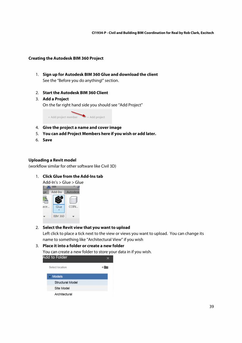
3. Add a Project
On the far right hand side you should see “Add Project”
4. Give the project a name and cover image
5. You can add Project Members here if you wish or add later.
6. Save
Uploading a Revit model
(workflow similar for other software like Civil 3D)
1. Click Glue from the Add-Ins tab
Add-In’s > Glue > Glue
2. Select the Revit view that you want to upload
Left click to place a tick next to the view or views you want to upload. You can change its
name to something like “Architectural View” if you wish
3. Place it into a folder or create a new folder
You can create a new folder to store your data in if you wish.

CI1934-P - Civil and Building BIM Coordination for Real by Rob Clark, Excitech
40
4. Under More Options, ensure you have Shared Coordinates selected
5. Click Glue It
Autodesk BIM 360 Glue will now upload your model to the servers. This takes a few minutes normally.
All project participants that have access to Autodesk BIM 360 Glue should also follow suit and upload
their models in the same way. This way the Lead Designer would have access to all the models to
combine them together. Alternatively, this collaboration can be done in Autodesk Navisworks using
workflow 4 as you are able to Glue federated models directly from Autodesk Navisworks. This
workflow is especially useful if one party does not have access to Glue or is not confident in
coordinating models.
Creating a merged model
1. Select Create New Merged Model
2. Select Models to merge
3. Give Federated Model a name and press OK
(yep, it really is that easy!)
You are now in a position to run a clash detection report within Autodesk BIM 360 Glue. This process
is very easy and is very similar to the Navisworks workflows in workflow 4.

CI1934-P - Civil and Building BIM Coordination for Real by Rob Clark, Excitech
41
Summary
Final tips and tricks
• Back up all of your data first
• Install the Autodesk Civil 3D Object Enablers
• Ensure Level and Coordinate markers are set to Survey Point in Revit
• Check it is set to Shared Coordinates for input
• Check the file reader units are set correctly
(above points are covered in detail in the “Before you do anything!” section
• Don't let Revit save the position back to the DWG
Revit will want to save the position back to the DWG. You must disable the positioning when
it asks this or you can mess up your survey / map file.
• When in Revit, turn your AutoCAD brain off
Don’t try to move models, draw to an origin or in the correct orientation of North, move the
world under the model, not the other way around, share your coordinates. The worlds of Revit
and AutoCAD are very different, the biggest mistake you can make is to think “AutoCAD”
when you should be thinking “Revit”.
• Sometimes it’s quicker to start again
Sometimes when I’m teaching this topic, people get a bit mixed up. Miss a step or do
something like mess up the coordinates in the AutoCAD drawing. They then naturally start
trying to unpick it. To date nobody has unpicked the problem faster than I can start again.
Final word
The importance of coordinating your data has never being more important than with the introduction
of Building Information Modelling process. You simply cannot get a building past the validation and
handover stages without coordination and so you can miss critical client expectations. Therefore I
hope you find all of the information contained here useful. I’d love to hear from you, get it touch!
Rob Clark
Consultant for Excitech Ltd (www.excitech.co.uk)
[email protected] / @clarkrob