CITY OF INDIANAPOLIS DEPARTMENT OF PUBLIC WORKS ... · 101.06 Pavement Joints I 101.07 Pavement...
198
Table of Contents i CITY OF INDIANAPOLIS DEPARTMENT OF PUBLIC WORKS INDIANAPOLIS TRANSPORTATION SECTION STANDARDS MANUAL PREFACE Purpose Marion County Thoroughfare Plan Sanitary District Standards Manual Stormwater Design And Construction Specification Manual Definitions and Abbreviations CHAPTER 100 STANDARDS FOR ACCEPTANCE FOR STREETS AND BRIDGES Page 100.01 Introduction ........................................................................................................ 1-2 100.02 Minimum Standards for Street and Bridge Construction ................................... 1-2 100.03 Minimum Standards for Street Design .............................................................. 1-2 100.04 Minimum Standards for Street Construction ..................................................... 1-4 100.05 Driveways .......................................................................................................... 1-6 100.06 Standard Plans .................................................................................................. 1-6 100.07 Effective Date .................................................................................................... 1-7 SECTION 101 General Index for Standards Figures 101.01 Typical Section - Local Street 101.02 Typical Section – Collector Street 101.03 Typical Section - Arterial Street 101.04 Half Typical Section - Divided Street 101.05 Typical Trail Cross-Section 101.06 Pavement Joints I 101.07 Pavement Joints II 101.08 Pavement Joints III 101.09 Joint Details 101.10 Concrete Roll Curb And Gutter 101.11 Combined Concrete Curb And Gutter 101.12 Depressed Roll Curb At Driveways 101.13 Monolithic Concrete Curb And Sidewalk 101.14 Concrete Curb 101.15 General Notes For Curb And Gutter 101.16 Sidewalk Details 101.17 Sidewalk Next To Existing Curb 101.18 Pavement Types And Thickness – Local Street 101.19 Pavement Types And Thickness – Collector Street 101.20 Pavement Types And Thickness – Arterial Street 101.21 Residential Driveways 101.22 Typical Driveway Section 101.23 Subdivision Cul-De-Sac 101.24 Subdivision Temporary Cul-De-Sac I 101.25 Subdivision Temporary Cul-De-Sac II 101.26 Alley Terminations (For Existing Or Rebuilt Alleys Only) 101.27 Street Terminations (For Existing Or Rebuilt Streets Only) 101.28 Typical Private Drive Access To Cul-De-Sac For Apartment Complex
Transcript of CITY OF INDIANAPOLIS DEPARTMENT OF PUBLIC WORKS ... · 101.06 Pavement Joints I 101.07 Pavement...

Table of Contents i
CITY OF INDIANAPOLIS
DEPARTMENT OF PUBLIC WORKS INDIANAPOLIS TRANSPORTATION SECTION
STANDARDS MANUAL PREFACE Purpose Marion County Thoroughfare Plan Sanitary District Standards Manual Stormwater Design And Construction Specification Manual Definitions and Abbreviations CHAPTER 100 STANDARDS FOR ACCEPTANCE FOR STREETS AND BRIDGES Page 100.01 Introduction ........................................................................................................ 1-2 100.02 Minimum Standards for Street and Bridge Construction ................................... 1-2 100.03 Minimum Standards for Street Design .............................................................. 1-2 100.04 Minimum Standards for Street Construction ..................................................... 1-4 100.05 Driveways .......................................................................................................... 1-6 100.06 Standard Plans .................................................................................................. 1-6 100.07 Effective Date .................................................................................................... 1-7 SECTION 101 General Index for Standards Figures
101.01 Typical Section - Local Street 101.02 Typical Section – Collector Street 101.03 Typical Section - Arterial Street 101.04 Half Typical Section - Divided Street 101.05 Typical Trail Cross-Section 101.06 Pavement Joints I 101.07 Pavement Joints II 101.08 Pavement Joints III 101.09 Joint Details 101.10 Concrete Roll Curb And Gutter 101.11 Combined Concrete Curb And Gutter 101.12 Depressed Roll Curb At Driveways 101.13 Monolithic Concrete Curb And Sidewalk 101.14 Concrete Curb 101.15 General Notes For Curb And Gutter 101.16 Sidewalk Details 101.17 Sidewalk Next To Existing Curb 101.18 Pavement Types And Thickness – Local Street 101.19 Pavement Types And Thickness – Collector Street 101.20 Pavement Types And Thickness – Arterial Street 101.21 Residential Driveways 101.22 Typical Driveway Section 101.23 Subdivision Cul-De-Sac 101.24 Subdivision Temporary Cul-De-Sac I 101.25 Subdivision Temporary Cul-De-Sac II 101.26 Alley Terminations (For Existing Or Rebuilt Alleys Only) 101.27 Street Terminations (For Existing Or Rebuilt Streets Only) 101.28 Typical Private Drive Access To Cul-De-Sac For Apartment Complex

Table of Contents ii
101.29 General Policy On Street Connections And Terminations 101.30 Minimum Residential Subdivision Entrance From A Thoroughfare 101.31 Auxiliary Lanes 101.32 Min. Residential Subdivision Entrance (1 Side Construction) 101.33 Auxiliary Lanes II 101.34 Pipe Underdrain I 101.35 Pipe Underdrain II 101.36 Street Signs 101.37 Pavement Tolerances And Testing – Concrete 101.38 Pavement Tolerances And Testing – Concrete 101.39 Full Depth Asphalt Pavement Construction, Tolerances And Testing 101.40 Full Depth Asphalt Pavement Construction, Tolerances And Testing 101.41 Monument Frame And Cover 101.42 Typical Monument Installation 101.43 Corner Section Monument 101.44 Backfill Requirement– Residential 101.45 Repair Of Cuts Within Pavement Limits 101.46 Temporary Repair Of Cuts Within Pavement Limits 101.47 Repair Of Cuts Within Pavement Limits- Cont. 101.48 Corner Parcel Access Drives 101.49 Single Lane Roundabout 101.50 Multi-Lane Roundabout 101.51 Roundabout Pavement Marking Details 101.52 Eyebrow 101.53 Minimum Residential Collector Requirement For Development

Table of Contents iii
CHAPTER 200 REGULATIONS FOR ACTIVITIES WITHIN PUBLIC RIGHT-OF-WAY 200.01 Introduction ........................................................................................................ 2-2 200.02 Standards For Traffic Control ............................................................................ 2-2 200.03 Restrictions Within The Public Right-Of-Way .................................................... 2-3 200.04 Minimum Standards For Compaction Or Deflection .......................................... 2-3 200.05 Enforcement Provisions ..................................................................................... 2-3 200.06 Bonding.............................................................................................................. 2-3 200.07 Enforcement Procedures ................................................................................... 2-4 200.08 Standards For Right-Of-Way Excavation .......................................................... 2-4 200.09 Standards For Restoration Of Public Right-Of-Way .......................................... 2-5 200.10 Inspection And Testing ...................................................................................... 2-15 200.11 Variance Procedure ........................................................................................... 2-15 200.12 Appeal................................................................................................................ 2-15 200.13 Indemnification .................................................................................................. 2-15 SECTION 201 General Index for Restoration Figures
201.01 Typical – Single Cut Restoration Limits 201.02 Typical – Multiple Cuts Restoration Limits 201.03 Typical – Trench Restoration Limits 201.04 Typical – Intersection Restoration Limits 201.05 Trench Restoration Detail for Asphalt Streets
CHAPTER 300 TRAFFIC SIGNAL DESIGN STANDARDS 300.01 Introduction ........................................................................................................ 3-2 300.02 Preface .............................................................................................................. 3-2 300.03 Salvaged Material .............................................................................................. 3-2 300.04 Permits ............................................................................................................... 3-2 300.05 General Conditions ............................................................................................ 3-3 300.06 Controller Bench Testing ................................................................................... 3-3 300.07 Controller Warranty ........................................................................................... 3-3 300.08 Controller Cabinet .............................................................................................. 3-4 300.09 Controller Surge Protection ............................................................................... 3-4 300.10 Controller Load Switches ................................................................................... 3-4 300.11 Controller Cabinet .............................................................................................. 3-5 300.12 Flasher Controller Cabinet Controller Detection Equipment ............................. 3-5 300.13 Traffic Signal Lamps .......................................................................................... 3-6 300.14 Traffic Signal Mast Arms ................................................................................... 3-6 300.15 Traffic Shop Drawings ....................................................................................... 3-6 300.16 Traffic Signal Loop Sealant ............................................................................... 3-7
Table of Contents iv
SECTION 301 Traffic Signal Standard Figures
301.01 Controller Cabinet Foundation Type P-1 301.02 Controller Cabinet Foundation Type M 301.03 Signal Pedestal Foundation Type A 301.04 Signal Handbar 301.05 Ring and Covers 301.06 Modified M to P-1 Foundation 301.07 Modified A to M Foundation 301.08 Modified A to P-1 Foundation 301.09 Signal Service & Controller on Wood Pole 301.10 Signal Service & Controller on Steel Pole 301.11 Signal Service on Wood 301.12 Signal Service on Wood Pole 301.13 Signal Indication Mounted on Steel or Wood Pole 301.14 Pedestal Mounted Signal Indication 301.15 Controller (G Cabinet) on Pedestal 301.16 Underground Service on Pedestal 301.17 Detector Housing Installation 301.18 Detector Housing 301.19 Detector Housing Adaptor 301.20 Traffic Signal Loop Installation 301.21 Traffic Signal Loop Installation 301.22 Traffic Signal Detector Housing Installation 301.23 Traffic Signal Loop Splice 301.24 Traffic Signal Loop Cabinet Connection 301.25 Loop Tagging System 301.26 Signal Mast Arm 301.27 Signal Mast Arm Details 301.28 Signal Mast Arm Foundation 301.29 Signal Mast Arm Details 301.30 Signal Mast Arm Data and Notes 301.31 Signal Pedestal Base and Anchor Bolts 301.32 Strain Pole Alignment 301.33 Strain Pole Foundation 301.34 Cabin Span Attachment 301.35 Span, Catenary & Tether Details 301.36 Side Mounted Signal on Steel Pole 301.37 Steel Strain Pole 301.38 Strain Pole Details 301.39 Strain Pole Band Details 301.40 Strain Pole Base Plate Details 301.41 Strain Pole Anchor Bolt Details
CHAPTER 400 CONCRETE CURB RAMPS 400.01 Introduction ........................................................................................................ 4-2 400.02 Concrete Curb Ramps ....................................................................................... 4-2 400.03 Location ............................................................................................................. 4-2 400.04 Types of Sidewalk Curb Ramps ........................................................................ 4-3 400.05 Selection Guidelines .......................................................................................... 4-5 400.06 Curb Ramp Lengths and Slopes ....................................................................... 4-6 400.07 Detectable Warning Devices ............................................................................. 4-6 400.08 Pedestrian Signal Controls ................................................................................ 4-6

Table of Contents v
SECTION 401 Curb Ramp Standard Figures
401.01 Intersection Showing Typical Curb Ramps And Inlet Locations 401.02 Roll Curb & Gutter Depressed Curb Detail (Type I)
CHAPTER 500 SHARED BICYCLE FACILITY STANDARDS 500.01 Introduction ........................................................................................................ 5-2 500.02 Terms ................................................................................................................. 5-2 500.03 General Design .................................................................................................. 5-2
CHAPTER 600 ACCESS CONTROL MANUAL 600.01 Introduction ........................................................................................................ 6-2 600.02 Protection of Lots Below Street Grade .............................................................. 6-2 600.03 Thoroughfare System ........................................................................................ 6-2 600.04 Driveway Standards .......................................................................................... 6-3 600.05 Plot Plan Specifications ..................................................................................... 6-3 600.06 Permit Procedures ............................................................................................. 6-4

Table of Contents vi
CHAPTER 700 COMMERCIAL DRIVES 700.01 Introduction ........................................................................................................ 7-2 700.02 Commercial Drive Width .................................................................................... 7-2 700.03 Commercial Drive Curve Return Radius ........................................................... 7-2 700.04 Auxiliary Lane .................................................................................................... 7-2 700.05 Acceleration, Deceleration and Passing Blister Lanes ...................................... 7-2 700.06 Concrete Curb ................................................................................................... 7-2 700.07 Concrete Curb Ramps ....................................................................................... 7-3 700.08 Material .............................................................................................................. 7-3 700.09 Permitting........................................................................................................... 7-3 CHAPTER 800 NEIGHBORHOOD TRAFFIC CALMING 800.01 Purpose ............................................................................................................ 8-2 800.02 Planning ............................................................................................................. 8-2 800.03 Description of Alternatives ................................................................................. 8-5 800.04 Speed Hump – Design and Construction Guidelines ........................................ 8-8 SECTION 801 Neighborhood Traffic Calming Standard Figures
801.01 Speed Humps 801.02 Pedestrian Refuge Island 801.03 Pedestrian Refuge Island 801.04 Curb Extension 801.05 Traffic Circle 801.06 Diagonal Diverter 801.07 Partial Diverter (Exit Only) 801.08 Partial Diverter (Entrance Only) 801.09 Street Closure (Cul-De-Sac) 801.10 Curb Radius Reduction 801.11 Chicane 801.12 On-Street Parking (Chicane)

Table of Contents vii
CHAPTER 900 INDIANAPOLIS CULTURAL TRAIL 900.01 Introduction ........................................................................................................ 9-2 900.02 General Design .................................................................................................. 9-2 900.03 Trail Widths ........................................................................................................ 9-2 900.04 Curb Ramps ...................................................................................................... 9-2 900.05 General Materials .............................................................................................. 9-2 900.06 Unit Pavers ........................................................................................................ 9-2 900.07 Surface Restoration ........................................................................................... 9-5 900.08 Trench Construction .......................................................................................... 9-5 900.09 Permitting........................................................................................................... 9-5 900.10 Construction ...................................................................................................... 9-5 SECTION 901 Indianapolis Cultural Trail Standard Figures
901.01 Separated Pedestrian/Bicycle Trail Section 901.02 Combined Pedestrian/Bicycle Trail Section 901.03.1 Typical Intersection Separated Pedestrian/Bicycle Trail Paver Layout 901.03.2 Typical Intersection Combined Pedestrian/Bicycle Trail Paver Layout 901.03.3 Typical Drive Approach Unit Paver Layout 901.03.4 Key Notes 901.04 Trench Restoration Detail C
CHAPTER 1000 TRANSIT STANDARDS 1000.01 Introduction ........................................................................................................ 10-2 1000.02 General Design .................................................................................................. 10-2

Preface
PREFACE
Purpose The purpose of this manual is to develop one document for standards for the
design and construction of roadways within Marion County, Indiana. These standards have incorporated various ordinances, resolutions and manuals currently being use by City of Indianapolis Department of Public Works (DPW) officials as of January, 2014.
DPW has jurisdiction over all thoroughfares in Marion County, except those
roads which are under the jurisdiction of Indiana Department of Transportation, INDOT. The DPW by intergovernmental agreement with the City of Indianapolis has control of all streets inside the corporate boundaries of Indianapolis.
Marion County The Marion County Thoroughfare Plan may be viewed on the Thoroughfare Indianapolis Metropolitan Planning Organization web site. Plan http://www.indympo.org
Sanitary District This manual does not contain any information for the Standards Manual construction of sanitary sewer infrastructure within the jurisdiction of
Indianapolis DPW. The Sanitary District Standards Manual may be viewed on the Indianapolis DPW web site.
http://www.indy.gov
Stormwater Design This Manual does not contain any information for the And Construction construction for storm sewer infrastructure Specification within the jurisdiction of Indianapolis DPW. The Stormwater Manual Design And Construction Specifications Manual may be viewed on the
Indianapolis DPW web site. http://www.indy.gov
Abbreviations and Wherever in these standards the following terms, abbreviations, or definitions Definitions are used, the intent and meaning will be interpreted as follows: 1. Abbreviations INDOT Indiana Department of Transportation DPW City Of Indianapolis Department Of Public Works DMD City of Indianapolis Department of Metropolitan Development MUTCD Manual on Uniform Traffic Control Devices AASHTO American Association of State Highway and Transportation
Officials 2. Definitions ADMINISTRATOR: Administrator of Division of Compliance BOARD: Board of Public Works, or its successor. BRICK RESTORATION AREA: Monument Circle, Market Street from Alabama
Street to Capitol Avenue, the spokes from Monument circle, brick streets in the Historical Areas and other designated by the Division.
PROTECTED STREETS: All streets or thoroughfares constructed or
resurfaced within five (5) years prior to the permit application date for asphalt streets and all streets constructed within fifteen (15) years prior to the permit application date for concrete streets.

Preface
NON-PROTECTED STREETS: All streets or thoroughfares, which are not
Protected Streets. BICYCLE LANE: Is a roadway that has pavement marking that designate a travel lane for bicycle traffic. DEPARTMENT: Department of Public Works DIVISION: City of Indianapolis Department of Metropolitan Development,
Division of Compliance EMERGENCY PERMIT: Any permit issued under these regulations which is
effective for no longer than forty-eight (48) hours. ENCROACHMENT LICENSE: A license (permit) required for any inanimate
object on, under, over, or upon the public right-of-way. HISTORICAL AREAS: All areas designated as historical areas by the
Metropolitan Development commission. INSPECTOR: A Division representative or any other person authorized by the
Division to perform inspections. NON-PAVED AREAS: All dirt, or grassy areas within the Public Right of Way. PARKING LANES: Any lane where parking is permitted at the time of the work
being performed. PERMIT HOLDER: Person to whom a permit described in these regulations
has been issued. PERSON: The term “person” shall include and be applied to associations,
clubs, societies, firms, partnerships and bodies politic and corporate as well as to individuals.
PUBLIC RIGHT-OF-WAY: REGIONAL CENTER: The area which is bordered by and includes the
following streets and public right-of-way: Sixteenth (16th
) Street on the north, College Avenue on the east, Morris Street on the south and White River Parkway, West Drive on the west. In addition, the area also includes Meridian Street from Sixteenth (16
th) Street through Thirty-Eighth (38
th) Street together
with the right-of-way of Meridian Street. SHARED BICYCLE FACILITY: Is the use of roadway to be shared by both
bicycles and motorized vehicular traffic. SHARED ROADWAY: Is a roadway that has sufficient width for safe bicycle
traffic, but is not designated in any manor. SIGNED SHARED ROADWAY: Is a roadway that has sufficient width for safe
bicycle traffic and is signed and designated as a bike route. SPECIAL EVENT(S): A large public event that in the determination of the
Division will require special restrictions on the use of City of Indianapolis Right of Way as it regards amount of permits issued during such events and the scheduling of work during such events. These events include, but are not limited to:
The Indianapolis 500 Festival Parade
The Indiana Black Expo Concert

Preface
The St. Patrick’s Day Parade
The Circle City Classic Parade
The Circle of Lights
The Indiana State Fair
NCAA Basketball “Final Four”
The Indianapolis 500
Allstate 400 at the Brickyard
Moto GP at the Indianapolis Motor Speedway
NFL Super Bowl, Pro Bowl, Draft and All Official Related Events
Big Ten Conference Championship Contests and All Official Related Events
NBA Finals or All-Star Activities and All Official Related Events
WNBA Finals or All-Star Activities and All Official Related Events
Any other event designated by the Mayor as a Civic Sponsored Event THOROUGHFARE: The term “thoroughfare” shall include all freeways,
expressways, primary arterials and secondary arterial, as defined and described in the Thoroughfare Plan for Marion County, Indiana latest edition.
TRAFFIC LANE: Any lane designated for vehicular traffic and not designated
as a parking lane. TRAFFIC CALMING: Is the combination of mainly physical measures that
reduce the negative effects of motor vehicle use, alter driver behavior and improve conditions for non-motorized street users.

CHAPTER 100 STANDARDS FOR ACCEPTANCE
OF STREETS AND BRIDGES

Chapter 100 1-2 Standards for Acceptance for Streets and Bridges
CHAPTER 100 Standards for Acceptance of Streets and Bridges 100.01 Introduction Standards for Acceptance of Streets and Bridges provide requirements, standards, and
procedures for acceptance of streets and bridges within the City of Indianapolis, Indiana and Marion County, Indiana.
Indianapolis Department of Public Works has jurisdiction over all roadway designated as
thoroughfares by the Department of Metropolitan Development of Marion County, except those which are under the jurisdiction of the Indiana Department of Transportation.
100.02 Upon written application to the Director of the Department of Public Works with Minimum Standards For supporting reasons and data, a variance from the requirements of this Section, based Street And Bridge upon good engineering judgment, may be granted by the Department of Public Works. Construction This variance, if granted, shall apply only to the particular streets or bridges between the
specified limits named in the application.
100.03 1. Designation of Street Classification Minimum Standards For Street Design The designation of street classification shall be approved by the Department of
Public Works in accordance with definitions of classification as specified by the Indiana Design Manual.
2. Pavement Width and Length a.) The geometric design criteria of urban and rural local street pavement,
including gutters and curbs shall be in accordance with the most current version of the Indiana Design Manual. The maximum total length of a dead-end street shall be six hundred and fifty (650) feet as measured from the intersection of centerline of the street intersection and the radius point of the cul-de-sac.
b.) All permanently dead-ended streets shall be terminated by cul-de-sacs.
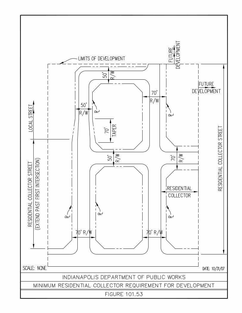
The minimum radius of cul-de-sacs on local streets and the minimum radius of curb entering and leaving the turn-around area shall be as shown on Figure 101.24. Temporarily dead-ended streets may be permitted in cases in which they are proposed to be and should logically be extended beyond the limits of the plat limits. Adequate easements for turnarounds shall be provided for such temporarily dead-ended streets which extended greater than one lot deep.
c.) The geometric design criteria of urban and local collector street pavement
including gutters and curbs, shall be in accordance with the most current version of the Indiana Design Manual.
d.) The minimum radius of cul-de-sacs on all streets not covered by
Subsection 100.03.2.b and the minimum radius of curb entering and leaving the turnaround area shall be shown on 101.24.
e.) If, during the preliminary planning phase, it is deemed necessary by the
Department of Public Works that a thoroughfare, or a portion thereof must be constructed, the developer may be required to construct only part of the full requirements set forth in the Thoroughfare Plan Ordinance 69-CPS-R5. If this is allowed, the street (and bridges if required) shall be designed in such a manner that the thoroughfare may be completed without disturbing this original work, and total proposed right-of-way shall be dedicated to the City of Indianapolis.

Chapter 100 1-3 Standards for Acceptance for Streets and Bridges
3. Minimum Right-of-Way The greater of the following shall be the minimum right-of-way required. a.) The right-of-way as set forth for future use in the Thoroughfare Plan
Ordinance 69-CPS-R5 as amended. b.) Local Streets; Fifty (50) feet; fifty (50) foot radius from center of Cul-de-sac. c.) Collector Streets: Seventy (70) feet. d.) In areas not zoned under the “Dwelling District Zoning Ordinance of Marion
County” at the time of submission of plans for approval: seventy (70) feet. e.) The right-of-way set fourth in Metropolitan Subdivision Control Ordinance
58-A0-13, as amended. f.) Divided streets and one-way streets: as determined by the Department of
Public Works. 4. Normal Crown The pavement crown for all streets shall be in accordance with the most current
version of the Indiana Design Manual. 5. Profile Grades a.) The maximum grade of freeways, and primary and secondary
thoroughfares shall be as determined by the Department of Public Works. b.) The maximum grade for local streets shall not exceed five (5) percent. c.) The maximum grade for local streets shall not exceed six hundred (600)
feet in total length where maximum grade shall not exceed twelve (12) percent.
d.) The maximum grade for cul-de-sacs within the turning area shall not exceed three (3) percent. e.) Minimum Grades The minimum grade of all streets shall be five-tenths (0.5) percent. 6. Design Speeds The design speed is that speed used for design of streets as set forth in the
Indiana Design Manual. It is intended that, through controls, both legal and geometric, the operating speed of a typical vehicle will be at or below the current thirty (30) miles per hour legal speed limit for urban districts as set forth in the statutes of the State of Indiana.
a.) The minimum design speed for collector streets shall be thirty (30) miles
per hour. b.) The minimum design speed for local streets shall be twenty (20) miles per
hour. c.) The minimum design speed for all other streets shall be as determined by
the Department of Public Works. 7. Minimum Stopping Sight Distance
The minimum stopping sight distance is based on the speed of the road and shall be in accordance with the most current version of the Indiana Design Manual.
8. Street Alignment

Chapter 100 1-4 Standards for Acceptance for Streets and Bridges
Horizontal and vertical curvature shall be in accordance with the most current version of the Indiana Design Manual.
9. Intersections
Intersection design shall be in accordance with the most current version of the Indiana Design Manual.
10. Sidewalks a.) In all platted subdivisions, the necessity of sidewalk installation shall be
governed by the Metropolitan Subdivision Control Ordinance 58-A0-13, as amended and any waivers thereof shall be obtained from the Plat Committee of the Department of Metropolitan Development prior to submission of construction plans for approval. A copy of such waiver shall be submitted with construction plans. For all other streets and bridges, the necessity of sidewalk installation shall be determined by the Director of the Department of Public Works.
b.) The minimum width of sidewalks shall be five (5) feet. c.) The desirable location of sidewalks shall be five (5) feet from the back of
the curb. 11. Driveways When shown on construction plans, each driveway shall be designed to meet the following regulations: a.) Chapter 700 of this manual; and b.) Chapter 100.05 of this manual. If driveways are not to be installed as a part of the construction a note to that effect shall be placed on the plans.
100.04 1. General Requirements Minimum Standards For Street Construction a.) Minimum requirements for street construction shall be in accordance with
the most current edition of “INDOT Standard Specifications” hereinafter referred to as the “Standard Specifications”, unless otherwise required by this Regulation.
b.) All Standard Specifications section No. references are based on 2012 Edition.
c.) A copy of the current edition of these Standard Specifications is found on the INDOT website or on file at the Department of Public Works.
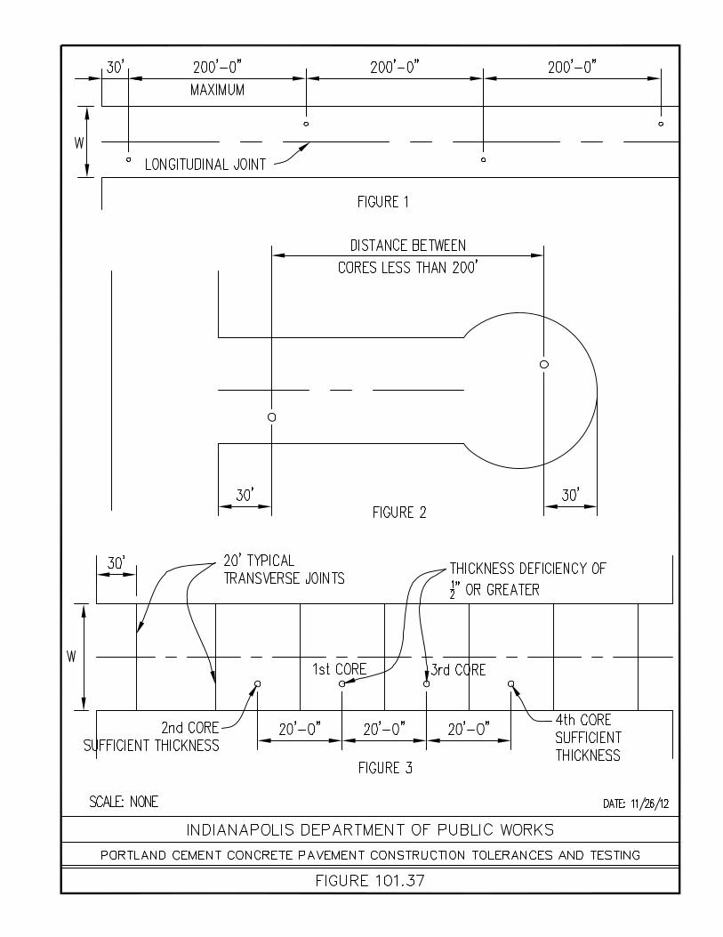
d.) Construction tolerance and testing shall be in accordance with the criteria and methods set out in Figures 101.37, 101.38, 101.39, and 101.40.
2. Preparation of Sub-grades for Rigid and Flexible Pavements The sub-grade shall be prepared in compliance with Section 207 of the INDOT
Standard Specifications. 3. Rigid Pavement (PCCP) Thickness a.) The minimum thickness of concrete pavement for local streets shall be six
(6) inches. b.) The minimum thickness of concrete pavement for residential collector
streets shall be seven (7) inches. c.) The minimum thickness of concrete pavement for commercial and industrial
collector streets shall be eight (8) inches. If it is projected that the street will have greater than ten (10%) percent truck traffic (average daily), the pavement thickness shall be nine (9) inches.

Chapter 100 1-5 Standards for Acceptance for Streets and Bridges
4. Rigid Pavement Materials and Methods of Construction a.) Portland cement concrete pavement, (PCCP), shall be constructed in
accordance with Section 502 of the Standard Specifications, except as provided below.
b.) Materials shall comply with Section 901 and Subsections 904.02, 904.03 and 913.01 of the Standard Specifications. Concrete shall be machine finished except on widened portions, intersections or other places where hand finishing will be permitted if authorized by the Department of Public Works.
c.) Conditioning of sub-grade shall be in accordance with Subsection 501.10 of the Standard Specifications.
d.) All joints shall be in accordance with Subsection 503.03 of the Standard Specifications, except:
1.) Weakened plane or dummy transverse contraction joints shall be placed not to exceed twenty (20) feet spacing. Transverse contraction joints may be wither formed or sawed dummy groove, ribbon or pre-molded strip type. One of the above named joints shall be placed at every catch basin and manhole in line of pavement. The location of joints: all joints must extend throughout side strips and curbs to full width pavement.
2.) Expansion joints, with approved dowel bar assembly, shall be placed at street intersections and where shown on the plans.
3.) Whenever the width between forms of the pavement under construction is greater than thirteen (13) feet, longitudinal joints shall be constructed so as to divide the pavement into strips not to exceed fifteen (15) feet each.
e.) Finishing machines or vibrating strike-boards of design other than as specified in the Standard Specifications will be permitted only if work of equal quality as set out in these specifications is obtained in the opinion of the Department of Public Works.
f.) Curing with approved impervious membrane or sealing compounds will be permitted if authorized by the Department of Public Works.
g.) All concrete shall be air entrained. 5. Flexible Pavement (Full Depth Asphalt) Thickness a.) The minimum thickness of full depth HMA for local streets shall be seven
(7) inches. b.) The minimum thickness of full depth HMA for residential collector streets
shall be nine (9) inches. c.) The minimum thickness for full depth HMA for commercial and industrial
collector streets shall be twelve (12) inches. If it is anticipated the street will have greater than ten (10) percent truck traffic (average daily) the thickness shall be thirteen (13) inches.
d.) The minimum thickness for full depth HMA for all other streets shall be as determined by the Department of Public Works.
6. Flexible Pavement Materials and Methods of Construction a.) HMA pavements shall be in accordance with Section 400, of the Standard
Specifications. These pavements shall consist of a one and one-half (1 ½) inch wearing surface, and the rest of the total asphalt section as described in Subsection 100.06.5, above, shall be base, placed in three and one-half (3 ½) inch maximum compacted lifts. The HMA surface shall be Type “B” mixture, and base shall be No. 4, No. 5 or No. 53B mixture. Construction joints in the same plane shall not be located within fifty (50) feet of a joint in the preceding lift.
b.) Materials shall comply with Section 900 the Standard Specifications. 7. Other Paving Materials

Chapter 100 1-6 Standards for Acceptance for Streets and Bridges
Upon application to the Director of the Department of Public Works, with supporting data from field tests, permission may be granted by the Department of Public Works to use other paving materials that have shown satisfactory performance.
8. Alternate Pavement Thickness a.) Upon application to the Director of the Department of Public Works, with
supporting data from field tests, alternate or lesser pavement thickness than those set forth in Subsections 100.04.3 and 100.04.5 may be approved by the Department of Public Works.
b.) Based upon experience in the vicinity of a proposed street or with soil of a similar mature, the Department of Public Works may require a pavement thickness greater than the minimum specified in Subsections 100.04.3 and 100.04.5, unless supporting data to the contrary is supplied.
9. Curb and Gutter a.) Curb and gutter shall be required for all streets b.) Curb and gutter shape shall be in accordance with the Figures 101.10,
101.11, 101.12, and 101.13. c.) Construction requirements shall comply with Section 605 of the Standard
Specifications. d.) Materials and conditioning of sub-grade shall be in accordance with the
provisions of Subsection 100.04.4.C. 10. Sidewalk Sidewalks shall be a minimum of four (4) inch thickness of Portland Cement
Concrete, conforming to Section 604 of the Standard Specifications and be as shown on Figure 101.17.
11. Park-strip a.) The park-strip (the area between the curb and sidewalk) shall be
constructed in accordance with Subsection 604.08 of the Standard Specifications
b.) The materials shall comply with Subsections 913.01, 913.03, 913.04 and 913.05 of the Standard Specifications
100.05 Driveways 2. Construction a.) Private residential driveways shall be constructed in accordance with
Figures; 101.21 and 101.22, and Subsections; 100.06.3 and 100.06.5, herein.
b.) Commercial driveways and their acceleration and deceleration lanes shall be constructed in accordance with Chapter 700 of this manual, and Section 100.04, parts 3, 4, 5, and 6.
100.06 1. Incorporation by Reference Standard Plans Attached hereto, and hereby incorporated herein by reference, are Standard
Plans, showing details of practices and design for portions of streets and/or/bridges for which acceptance may be requested of the Department of Public Works. These Standard Plans are hereby declared to be the Official Standard Plans for the City of Indianapolis for the purpose of achieving uniformity

Chapter 100 1-7 Standards for Acceptance for Streets and Bridges
of construction methods, materials and appearance. The said Standard Plans must be followed in construction of applicable portions of streets and bridges to be accepted by the Transportation Board, unless written permission for deviation there from is given by the Department of Public Works. The various applicable Standard Plans, with their effective dates shall be listed on all construction plans submitted for approval to the Department of Public Works.
2. Revisions, Deletions and Additions to Standard Plans The Director of Public Works is hereby granted the power and authority to revise
the Standard Plans, to delete any of the, and/or to adopt new Standard Plans, when, in his judgment, such revisions, deletions or additions shall be necessary or helpful in order to give guidance to developers and to achieve the purpose of this Regulation. Any new or revised Standard Plan adopted after the effective date of this Regulation shall become effective on the date stated thereon which shall be a minimum of thirty (30) days after its approval be the Director of Public Works and shall apply to all construction plans submitted for approval after such effective date. The Department of Public Works shall make reasonable efforts to give notice of all new or revised Standard Plans to all persons or firms who may be affected thereby, or who shall request such notice.
100.07 This Regulation shall be in full force and effect immediately upon its passage by the Effective Date City-County Council, approved by the Mayor, and compliance with all laws pertaining
thereto.

Chapter 100 1-8 Standards for Acceptance for Streets and Bridges
SECTION 101 General Index For Figures
101.01 Typical Section - Local Street 101.02 Typical Section – Collector Street 101.03 Typical Section - Arterial Street 101.04 Half Typical Section - Divided Street 101.05 Typical Trail Cross-Section 101.06 Pavement Joints I 101.07 Pavement Joints II 101.08 Pavement Joints III 101.09 Joint Details 101.10 Concrete Roll Curb And Gutter 101.11 Combined Concrete Curb And Gutter 101.12 Depressed Roll Curb At Driveways 101.13 Monolithic Concrete Curb And Sidewalk 101.14 Concrete Curb 101.15 General Notes For Curb And Gutter 101.16 Sidewalk Details 101.17 Sidewalk Next To Existing Curb 101.18 Pavement Types And Thickness – Local Street 101.19 Pavement Types And Thickness – Collector Street 101.20 Pavement Types And Thickness – Arterial Street 101.21 Residential Driveways 101.22 Typical Driveway Section 101.23 Subdivision Cul-De-Sac 101.24 Subdivision Temporary Cul-De-Sac I 101.25 Subdivision Temporary Cul-De-Sac II 101.26 Alley Terminations (For Existing Or Rebuilt Alleys Only) 101.27 Street Terminations (For Existing Or Rebuilt Streets Only) 101.28 Typical Private Drive Access To Cul-De-Sac For Apartment Complex 101.29 General Policy On Street Connections And Terminations 101.30 Minimum Residential Subdivision Entrance From A Thoroughfare 101.31 Auxiliary Lanes I 101.32 Min. Residential Subdivision Entrance (1 Side Construction) 101.33 Auxiliary Lanes II 101.34 Pipe Underdrain I 101.35 Pipe Underdrain II 101.36 Street Signs 101.37 Pavement Tolerances And Testing - Concrete 101.38 Pavement Tolerances And Testing - Concrete 101.39 Full Depth Asphalt Pavement Construction, Tolerances And Testing 101.40 Full Depth Asphalt Pavement Construction, Tolerances And Testing 101.41 Monument Frame And Cover 101.42 Typical Monument Installation 101.43 Corner Section Monument 101.44 Backfill Requirement– Residential 101.45 Repair Of Cuts Within Pavement Limits 101.46 Temporary Repair Of Cuts Within Pavement Limits- Cont. 101.47 Repair Of Cuts Within Pavement Limits- Cont. 101.48 Corner Parcel Access Drives 101.49 Single Lane Roundabout 101.50 Multi-Lane Roundabout 101.51 Roundabout Pavement Marking Details 101.52 Eyebrow 101.53 Minimum Residential Collector Requirement For Development


CHAPTER 200 REGULATIONS FOR ACTIVITIES
WITHIN RIGHT-OF-WAY

Chapter 200 2-2 Regulations For Activities Within Public Right-Of-Way
CHAPTER 200 Regulations For Activities Within Right-Of-Way
200.01 The following subsection is a digitally reproduced copy of the Regulations For Activities Introduction Within Public Right-Of-Way. The original regulations were adopted October, 2001 and
were readopted by Resolution No. 89, 2006, December, 2006. Regulations for Activities Within Right-Of-Way provides standards, restrictions,
procedures, and testing requirements for any construction activities within the City Of Indianapolis’s right-of-way
200.02 Standards for traffic control for construction and maintenance operations in, on, under Standards For Traffic and over the public right-of-way. Control 1. Traffic control for construction and maintenance activities in, on, under and over
the public right-of-way shall conform to and be in accordance with the Indiana Manual of Uniform Traffic Control Devices, latest edition, and all other applicable state and federal laws.
2. The permit applicant or permit holder may propose to the Division that traffic
control less stringent than those described above in paragraph 200.02.1 be implemented as part of a specific permit. If in the opinion of the Department/Division, conditions exist that would allow the use of less stringent traffic control, the division may issue the specific permit submit to the less stringent control. However, at a minimum, the traffic control measures must include:
A. All traffic control devices shall: (a) conform to the applicable specifications contained in the Indiana
Manual on Uniform Traffic Control Devices in effect at the time. (b) be installed prior to commencement of operations. (c) be properly maintained and utilized during operations, and (d) be removed immediately upon completion of the work. B. Barricades and sign supports shall be constructed and erected in a
workmanlike manner and should be constructed as per INDOT design standards in regards to impact yield requirements.
C. Where illumination is required, street or highway lighting is not regarded as
meeting this requirement. D. A vehicle having an arrowboard shall be placed near said work area in such
a position that the flashing light or arrowboard is visible to approaching traffic in the lane in which such work is being performed for at least 1,000 feet if the speed limit in the work area is 30 mph or less or 1,500 feet if the speed limit is greater than 30 mph. In addition, traffic cones or barrels shall be used to the extent required by the Department/Division to protect the public and the workmen on the scene.
E. Initial and secondary warning signs need not be used if a vehicle having a
flashing light or arrowboard is placed near such work area in such a position that the flashing light or arrowboard is visible to approaching traffic in the lane in which such work is being performed for at least 1,000 feet if the speed limit in the work area is 30 mph or less or 1,500 feet if such speed limit is greater than 30 mph.

Chapter 200 2-3 Regulations For Activities Within Public Right-Of-Way
3. The Division may suspend work or operations at any worksite which it
determines endangers the traveling public or the workmen on the scene until the circumstance which endangers the traveling public or the workmen on the scene is corrected or eliminated.
200.03 Restrictions with respect to when and how work should be performed in public rights-of- Restrictions Within The way in certain geographical areas. Public Right-Of-Way The contractor shall minimize all utility markings within the Regional Center. The
contractor shall remove all utility location markings that exceed five (5’) feet on either side of the trench, or that exceed a five (5’) foot radius of the work being performed within the right-of-way. Also, the contractor shall remove all utility location markings on the curb and sidewalks that are not removed due to restoration.
200.04 Compaction shall be performed in accordance with one of the following methods. Minimum Standards For Compaction Or Deflection 1. Up to the final 12 (12”) inches of fill, maximum loose lifts and compact each layer
by mechanical means to at least ninety-five percent (95%) of its maximum wet density, or
2. Up to the final 12 (12”) inches of fill, 24 (24”) inch maximum loose lifts and
compact each layer by a combination of saturation and mechanical means to at least ninety-five percent (95%) of its maximum wet density, maximum dry density shall be determined in accordance with ASTM Designation D 698.
3. The final 12 (12”) inches of fill shall be compacted to 100% of its maximum dry
density.
200.05 Enforcement of the provisions of Article VII and/or the regulations are as follows: Enforcement Provisions 1. The Division shall have the authority to assess a Two Hundred Fifteen dollars
($215.00) administrative fee each and every instance where enforcement of the provisions of Article VII or where the regulations require the Division to re-inspect the worksite.
A violation of this section is subject to the enforcement procedures and penalties
provided in Section 103-3 of the Revised Code of the Consolidated City and County, Indianapolis, Marion County, Indiana; provided, however, the fine imposed for such violation shall not be less than one hundred dollars ($100.00), and each day that an offense continues shall constitute a separate violation. The City controller shall cause any fines collected under this section to be deposited into an account for the use and benefit of the Division.
200.06 Bonding Bonds. The performance bond posted with respect to each permit shall not be released
until an approved inspection is received on the restoration of the public right-of-way. The applicant shall either file or have on file with the Division of Compliance a

Chapter 200 2-4 Regulations For Activities Within Public Right-Of-Way
performance and maintenance bond. The company writing the bonds shall be licensed/listed to do business in Marion County. The performance bond shall be in the penal amount of not less than Ten Thousand Dollars ($10,000.00) for a single street cut or One Hundred Thousand Dollars ($100,000.00) for unlimited multiple street cuts in any one calendar year. The bond shall be in effect for a duration of three (3) years from the date of issuance of each permit. The applicant shall also furnish the Division with a maintenance bond for each application which shall be in effect for a minimum period of three (3) years after completion of the work. All bonds shall be for the use and benefit of the division and the City of Indianapolis.
200.08 In general. All work within a public right-of-way for which a right-of-way excavation Standards For Right-Of- permit is required shall be performed in accordance with, and conform to, the standards Way Excavation of this section. Worksites. The permit holder/contractor is responsible for having uniformed police
officers at the site at all times. All such officers shall have Indiana Law Enforcement Association Certification (ILEA) or Indiana Police Department (IPD) Academy training. The number of officers required will be determined by the Division.
Color coding. All work in the right-of-way which disturbs roadway surfaces, improved
shoulders, improved curbs and sidewalks shall be color coded using the Color Coding System described in IC 8-1-26-18. to the extent not conflicting with the above, the following color code shall also be used:
Silver – All work performed by the city agencies which is not designated by the above
color codes shall be identified by silver color. 1. Temporary and partial restoration shall be color coded with a paint which will
remain visible until the final restoration is made. 2. No paint shall be used on brick pavement or brick sidewalks within the downtown
area. Removal of surface. As a general rule, the minimum size of all cuts shall be four (4’)
feet by four (4’) feet, unless a lesser size is specifically allowed by the Division. One by one (1 x 1) disconnect cuts with a vacuum truck will be allowed as needed. Where applicable, erosion control shall be addressed and approved by the inspector prior to beginning work.
1. Concrete Streets and Alleys. Two methods of concrete surface removal are
acceptable: A. All cuts shall be saw-cut to one-third (1/3) the depth of the pavement with a
concrete saw. A minimum saw cut depth of two (2”) inches is required. The cut shall then be completed with a mechanical hammer equipped with a suitable chisel, starting from the center of the cut.
B. All cuts shall be saw-cut full depth of the pavement with a concrete saw. All cuts shall be made at pavement joints. When any portion of a panel is
cut on Class I Streets or Class II Streets, the entire panel shall be removed and replaced. The minimum panel length shall be ten (10’) feet.
2. Asphalt Streets and Alleys. All cuts shall be saw-cut to a minimum of one-third (1/3) the depth of the
pavement and then completed with a mechanical hammer equipped with a

Chapter 200 2-5 Regulations For Activities Within Public Right-Of-Way
suitable chisel, starting from the center of the cut. A minimum saw cut depth of two (2”) inches is required.
Before final repairs are made, the cuts shall be “squared”. The edges of all cuts
are to be straight. 3. Brick Streets and Alleys. All bricks from the Brick Restoration Area shall be
salvaged for use in permanent restoration. 4. Asphalt over Concrete or Brick. A. All cuts shall be saw cut to the full depth of the asphalt and then completed
with a mechanical hammer equipped with a suitable chisel, starting from the center of the cut. The edges of the asphalt are to be straight.
B. Brick Removal. All bricks removed (excluding those described in paragraph
(3) above) may become the property of the Division at the direction of the Division/Department and shall be delivered to off-site storage within the city, as directed by the Inspector.
5. Shot Seal Streets and Alleys. All cuts shall be made by a mechanical hammer
equipped with a suitable chisel. The edges are to be straight and parallel. 6. Stone and/or Gravel Streets and alleys. All cuts may be made by mechanical or
manual means. 7. Sidewalks and Driveways. A. One method of concrete surface removal is acceptable: i. All concrete surface cuts shall be saw-cut to one-third (1/3) the depth
of the pavement with a concrete saw. A minimum saw cut of two (2”) inches is required. The cut shall then be completed with a mechanical hammer equipped with a suitable chisel, starting from the center of the cut. All cuts shall be made at pavement or panel joints. All panels that are cut shall be removed and replaced.
B. One method of asphalt surface removal is acceptable: i. All asphalt surface cuts are to be saw-cut to a minimum depth of two
(2”) inches and then completed with a mechanical hammer equipped with a suitable chisel, starting from the center of the cut. The edges of all cuts are to be straight.
200.09 In general. Upon completion of work, restoration of the public right-of-way shall be Standard For Restoration performed in accordance with the following standards: Of Public Right-Of-Way Specifications of materials. All materials, unless specifically stated otherwise, shall be in
accordance with current Indiana Department of Transportation Standard Specifications: 1. BACKFILL A. B Borrow
As defined in the most current version of the INDOT Standard Specifications.
B. Structure Backfill

Chapter 200 2-6 Regulations For Activities Within Public Right-Of-Way
As defined in the most current version of the INDOT Standard Specifications.
C. Flowable Backfill
As defined in the most current version of the INDOT Standard Specifications.
2. CONCRETE All concrete shall be in accordance with section 502 of the most current version
of the INDOT Standard Specifications. Retempering concrete by adding water or by other means will not be permitted
for continuous operation. When concrete is delivered in transit mixers or agitators, water may be added and additional sizing performed in particular cases to increase the slump. The addition of water and mixing may be under the direction of a Department Representative.
3. ASPHALT
A. HMA, INDOT SECTION 402 MIXES
1) INDOT Standard Specifications, Section 402, shall apply with the exceptions as noted herein. The most current version of the INDOT Specifications, Recurring Special Provisions, and Supplemental Specifications are applicable.
a. Description: This work shall consist of one or more courses of
HMA base, intermediate, surface mixtures or other miscellaneous HMA application, produced from an INDOT Certified HMA plant, in accordance with Indiana Test Method (ITM) 583.
b. Design Mix Formula and Mixture Type: The design mix formula,
prepared in accordance with 402.05, shall be based on the following table:
Mixture Type Type A * Type B* Type C* Type D *
Design ESAL 200,000 2,000,000 9,000,000 11,000,000
AADT <4000 4000- 15,000 15,000-30,000 >30,000
Surface 9.5, 12.5 mm 9.5, 12.5 mm 9.5, 12.5 mm 9.5, 12.5 mm
Surface - PG Binder 64-22 64-22 70-22 76-22
Intermediate 9.5, 12.5,19.0 mm 9.5, 12.5,19.0 mm 9.5, 12.5, 19.0mm 9.5, 12.5,19.0 mm
Intermediate - PG Binder 64-22 64-22 64-22 76-22
Base 25.0 mm 25.0 mm 25.0mm 25.0 mm
Base - PG Binder 64-22 64-22 64-22 64-22
*A higher category mix may be used for a lower category application.
c. Mixture Designation: Surface course Mixture Designation shall be 9.5 mm for all mixture types unless otherwise specified in the Drawings.
Intermediate course Mixture Designation shall be 19.0 mm for all mixture types unless otherwise specified in the Drawings. Base course Mixture Designation shall be 25.0 mm for all mixture types unless otherwise specified in the Drawings.
Chapter 200 2-7 Regulations For Activities Within Public Right-Of-Way
2) Recycled Materials
a. Recycled Asphalt Pavement: (RAP): Type A & B &C Surface: Maximum 25% RAP, no change in PG Binder grade. Base & Intermediate: Maximum 35% RAP, no change in PG Binder
grade for 25% or less RAP, for greater than 25% RAP change PG Binder Grade as shown below.
Type D Surface: Maximum 15% RAP, no change in PG Binder grade. Intermediate: Maximum 25% RAP, no change in PG Binder grade
for 15% or less RAP, for greater than 15% RAP change PG Binder Grade as shown below.
Base: Maximum 35% RAP, no change in PG Binder grade for 25% or less RAP, for greater than 25% RAP change PG Binder Grade as shown below:
PG 64-22 to PG 58-28 PG 70-22 to PG 64-28 PG 76-22 to PG 70-28
b. Recycled Asphalt Shingles (RAS) RAS may be used as a substitute for new materials. RAS shall consist of waste from a shingle manufacturing facility or tear-off shingles from roofs (post consumer). RAS shall meet AASHTO specification MP 15, Standard Specification for Use of Reclaimed Asphalt Shingle as an Additive in Hot Mix Asphalt and the mix design shall be done according to AASHTO PP 53 Standard Practice for Design Considerations When Using Reclaimed Asphalt Shingles in New Hot Mix Asphalt.
Up to 5% RAS may be used when the source is manufacturer waste. Up to 3% RAS can be used when source is post consumer. For equivalent RAP calculation, 1% of RAS shall be counted as equivalent to 5% RAP. Maximum allowable percentage of RAP plus equivalent RAP shall not exceed the limits listed under Recycled Asphalt Pavement (RAP) above. Asphalt binder grade should be selected based on the total RAP according to the guideline listed under Recycled Asphalt Pavement (RAP). When shingles are included as part of the allowable RAP percentage the ratio of added new asphalt binder to total asphalt binder shall be 70% or greater ((added binder/total binder) x 100 >= 70)
c. Surface Aggregate Type: For Type C Mixtures, surface
aggregates shall meet the requirements for less than 3,000,000 ESAL in Section 904.03(d). For Type D mixtures, surface aggregates shall meet the requirements for less than 10,000,000 ESAL in 904.03(d).R
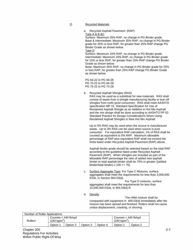
d. Density
The HMA mixture shall be compacted with equipment in 409.03(d) immediately after the mixture has been spread and finished. Rollers shall not cause undue displacement, cracking, or shoving.
Number of Roller Applications
Rollers
Courses < 440 lb/syd (240 kg/m
2)
Courses > 440 lb/syd (240 kg/m
2)
Option 1 Option 2 Option 3 Option 4 Option 1 Option 2

Chapter 200 2-8 Regulations For Activities Within Public Right-Of-Way
Three Wheel 1 2 3 4 1 2
Pneumatic Tire 2 4 4
Tandem 2 4 4
Vibratory Roller 6 8
e. Acceptance of Mixtures: Acceptance shall be based on 402.09.
The HMA Certification shall include the PG Binder grade sent to the project. B. TACK COAT shall be used in accordance with Section 406 of the INDOT Standard Specifications C. MULTIGRADE COLD MIX 1) Description. A bituminous patching material of a composition suitable
for premixing, stockpiling and storage prior to use. 2) Aggregate. The aggregate shall be of a grading such that the
specified composition will be obtained. A single aggregate or a blend of aggregates may be used. The aggregate used shall meet the requirements of AASHTO M43 for coarse aggregates Class A except the percent weight of fractured pieces shall be minimum 85% and the absorption shall be 3.0% maximum.
3) Bituminous Materials. Bituminous material shall be CM-300 and CM-
150 meeting special provisions. The CM-300 mix shall be used between November 30 and April 1. The dates are subject to change according to a project manager.
4) Composition. The completed mixture shall have a composition as
directed by the Engineer within the following limits: Sieve % Passing 1 ½” 100 1 70-98 ¾” 50-90 ½” 30-70 3/8” 20-60 #4 15-35 #8 3-30 #30 2-20 #300 0-5 Bitumen 3.0-4.5 CM-150 (Summer) 4.5-6.0 for CM-300 (Winter) 4. Topsoil, agricultural limestone, fertilizer, grass seed, mulch, soil, curing
compound and joint material are to be according to current “INDOT Standard specifications” and all revisions and addenda to that document.
Specifications for Backfill. All excavations shall be backfilled as follows. All cuts made
in, on or under any road surface, or road that is to be constructed where infrastructure will be placed, shall be backfilled with Flowable Backfill or Structure Backfill. Where a cut is outside the road surface, Flowable Backfill or Structure Backfill shall be placed in that portion of the cut located within five (5’) feet of the road surface on all streets. All cut areas not under pavement but under sidewalk shall be backfilled with B borrow or

Chapter 200 2-9 Regulations For Activities Within Public Right-Of-Way
Structure Backfill. All cut areas not under pavement or sidewalk shall be topped with four (4”) inches of topsoil for final restoration.
For storm and sanitary sewers, pipe bedding shall be in accordance with the
Department’s/Divisions’ Stormwater Design and Construction Specifications Manual, the Indianapolis Sanitary District Standards for the Design and Construction of Sanitary Sewers and Pipe Manufacturer’s recommendations.
The following general backfill requirements are established:
Trenches made in streets shall be backfilled with flowable backfill. Structure backfill may be used when the trench is greater than four (4’) feet in width.
The backfill operation shall be completed using one of the following methods. 1. Flowable fill. A. Placement. The mixture shall be discharged from mixing equipment by a
reasonable means into the space to be filled. Each filling stage shall be as continuous as is practicable. Concrete may be placed on fill as soon as bleeding water has subsided. All pavements shall be placed according to flowable backfill manufacturer’s recommendations.
B. Limitations. Flowable backfill shall be protected from freezing until the
material has stiffened and bleeding water subsided. As the temperature nears freezing, additional curing time may be needed.
2. B borrow or Structure Backfill. A. Placement. All structure backfill material shall be placed in maximum
twelve (12”) inch loose lifts. The first lift of fill surrounding the pipe will be allowed in one (1) loose lift of two (2’) feet to allow for the protection of the line being placed. Each lift of material must be compacted by mechanical means or by a combination of saturation and mechanical means to achieve at least ninety-five (95%) percent of its maximum wet density. If any method other than listed above is used, random testing may be required. The permit holder shall provide compaction testing. The test shall be performed and certified to the Division/Department by properly certified personnel.
3. Earth Backfill. Earth backfill may be used in locations not requiring granular
backfill. The earth backfill shall be made compatible with the adjacent surface. In established lawn areas, this includes compacting in not less than two lifts for each five (5’) feet of depth of the cut, topping off with topsoil, fertilizing, seeding, mulching and restoring all contours. If the slope is greater than 3:1, restoration of the grass shall be made by sodding or with straw mats.
Temporary surface restoration. Between November 30 and April 1, cuts may be
repaired in accordance with this section. Any cut temporarily repaired under this section shall be permanently repaired, by removing the temporary patch in its entirety and permanently restoring the cut as required in Permanent Surface Restoration of this regulation. The temporary patch shall be defined as the material filling the space that the permanent surface restoration will occupy. Final restoration on all cuts shall be made within thirty (30) days of completion of temporary repair with the exception of the Regional Center which shall be restored within fourteen (14) days. All cuts repaired under this section shall have final restoration completed by June 1. The permit holder shall notify the Division/Department within two (2) business days of completion of final restoration. It shall be the permit holder’s responsibility to maintain the temporary patch until the final surface restoration may be made.
If a temporary surface repair is used, it shall be made as follows:

Chapter 200 2-10 Regulations For Activities Within Public Right-Of-Way
1. Backfill shall be brought to within twelve (12”) inches of the surface, and a
concrete cap shall be placed flush and contiguous with the existing pavement grade; or
2. While work is continually in progress, the cut may be covered with steel plates
having a minimum thickness of three-fourths (3/4”) inch which shall be secured so as not to move and constitute a hazard when open to traffic.
Permanent surface restoration. All cuts shall be repaired permanently in accordance
with this section. The restoration of the surface of all cuts shall be completed by such methods and in such manner that the plane of the surface of the repair, at the time of completion and thereafter, will be flush with all contiguous surfaces and will create no dissymmetry with the topography of the roadway. Also, the final surface elevation shall be flush and contiguous with the original surface. The surface restoration may be made by using milling, infrared or future technologies approved by the Department, unless a specific method is required by the permit or by the inspector. All restoration shall be made in accordance with ADA Standards for Accessible Designs. The permit section reserves the right to require adherence to interim ADA rules created by the Department of Justice Access Board when it is in the best interest of the public to do so.
The Contractor shall restore all pavement markings within the pavement surface
restoration area included but not limited to any special pavement markings. The contractor shall minimize all utility markings within the Regional Center. The Contractor shall remove all utility location markings that exceed five (5’) feet on either side of the trench, or that exceeds a five (5’) foot radius of the work being performed within the right-of-way. Also, the contractor shall remove all utility location markings on the curb and sidewalks that are not removed due to restoration.
1. Concrete Streets and Alleys. Final repairs to concrete streets and alleys are to
be made with concrete. All streets shall be repaired with concrete in accordance with Section 502 High Early Strength Pavement of the current INDOT Standard Specifications. The existing pavement thickness shall be matched, but a minimum thickness of six (6”) inches is required. When repairing or replacing reinforced concrete, either (a) the steel reinforcement shall be replaced in kind (temporarily bending the reinforcing steel out of the way and then bending it back into position when the concrete is replaced) and properly fastened to the adjacent reinforcement, or (b) #5 bars, two (2’) feet long, shall be drilled and grouted into the existing pavement sides one (1’) foot deep at two (2’) foot on-center spacing with a minimum of two bars per side. All new concrete shall be protected against excessive dehydration by the application of a membrane type curing compound white pigment or soy bean oil concrete cure. Seal meeting ASTM c-309 shall be used on all new concrete within the right-of-way. The new concrete shall be protected from all traffic for forty-eight (48) hours. If this is done by the use of plates, the plates shall be steel with a minimum, three-fourths (3/4”) inch thickness. These plates shall be secured so as not to move or constitute a hazard when they are open to traffic.
2. Asphalt Streets and Alleys. Restoration on all one by one (1 x 1) cuts will be a
final restoration size of two by two (2 x 2). Utility access boxes/covers may be adjusted or replaced without resurfacing. The existing pavement thickness shall be matched, but a minimum thickness of twelve (12”) inches for Class I Streets and Class II Streets and seven (7”) inches for Class III Streets is required. The base material used in connection with all final repairs to asphalt streets and alleys shall be hot asphalt mix or concrete. One and one-half (1 ½”) inches hot asphalt surface shall be used on any asphalt surface street repair, except when repairs are made to any street which has been assigned a Department project number for resurfacing, in which case the one (1 ½”) inch HMA surface may be deleted and the base material brought up to the level of the existing pavement and this exception is only granted by written consent of the Department of Public Works. All edges or joints of existing pavement shall be thoroughly cleaned and tack coated prior to the placement of the HMA surface. All faces of exposed

Chapter 200 2-11 Regulations For Activities Within Public Right-Of-Way
curbing shall be tacked below the finished pavement elevation. All joints shall be sealed with a hot iron, infrared technology or other method as specified by the permit or as directed by the Division/Department.
A. Infrared Repair. Area of repair shall be cleaned of all loose material.
Repair area shall be uniformly heated to a depth of one and one-half (1 ½”) inches to two (2”) inches. Heating shall be done with a manufactured power operated machine of the heat-patcher type using only 100% infrared heat guaranteed not to damage asphalt. Machine shall be capable of uniformly heating the existing surface to depth of one and one-half (1 ½”) inches to two (2”) inches. Heated asphalt shall be added to the repair area to bring it flush with the existing grade and raked together with the surrounding heated asphalt to a workable condition. The material shall be compacted to a minimum of ninety-five (95%) percent of controlled density as per modified marshal test. All seams shall be sealed prior to final rolling. A light coating of pavement rejuvenating penetrant will be sprayed over the scarified and compacted material at a rate of 0.02 gallon per square foot. The finished patch shall be level with the existing surrounding pavement.
B. The following cases shall require resurfacing as indicated in Figures
201.01, 201.02, 201.03, and 201.04, which is attached hereto and incorporated herein:
i. When an excavation is cut on any Class I Streets or Class II Streets,
any lane impacted shall be minimum pavement patch shall be twenty-five (25’) feet in length with a minimum two (2’) feet cut back from the end of the cut.
ii. When a diagonal cut is made, the area shall be “squared” off. Any
lane impacted within the squared off area shall be completely resurfaced the entire width of the lane. The minimum pavement patch length shall be twenty-five (25’) feet in length with a minimum two (2’) feet cut back from the end of the cut.
iii. In addition to the above, if a cut on a Class I Street overlaps the
centerline of an existing road, the street shall be restored from curbline to curbline or from lane to lane so that the area affected has been properly restored.
3. Brick Streets and Alleys. Brick Streets within the Brick Restoration Area shall be
restored to their original surface condition and pattern. At the discretion of the Division, brick alleys shall be restored to their original surface condition and pattern. All new concrete shall be protected against all excessive dehydration by the application of a membrane type curing compound. The new concrete shall be protected from all traffic for forty-eight (48) hours. If this is done by the use of plates, the plates shall be secured so as not to move and so as not to constitute a hazard when they are open to traffic. Special attention needs to be given to the Historical Areas. All streets within the Historical Areas must be restored to their original condition.
A. RESET BRICK PAVERS i. Permittee must carefully remove and replace the existing brick pavers to
provide a smooth surface matching the existing pattern and to regrout brick joints.
ii. Permittee shall protect the surrounding undisturbed brick and asphalt
bed from loss of bedding or misalignment of brick. Any brick or setting bed outside of the repair area that is disturbed by the permittee shall be reset per City’s specifications.
Chapter 200 2-12 Regulations For Activities Within Public Right-Of-Way
iii. Prior to application of the joint regrouting, the permittee shall reset any paver that does not comply with the tolerance specification.
iv. Each reusable brick may require minor cleaning to remove existing
asphalt bedding or grout. If reusable bricks are replaced upside-down, the Permittee shall adequately clean each brick so that the new work will match the color of the existing adjoining brick.
B. CONSERVATION OF EXISTING BRICK i. The Permittee shall exercise great care in reusing and protecting all
existing bricks. Any damage will not be tolerated. C. PERSONALIZED BRICKS i. There are locations where personalized bricks may be found. The
Permittee shall take care to replace any personalized brick within the patch area. After regrouting, all grout shall be removed from the personalized brick so that the lettering is clear. Personalized bricks are located at: East Market St. between Monument Circle and Pennsylvania St.; West Market St. between Monument Circle and Illinois St; North Meridian St. between Monument Circle and Ohio St.; North Meridian St. between Monument Circle and Washington St.
D. SETTING BED FOR BRICK PAVERS (STREET AND SIDEWALK)
i. The Permittee shall remove loose setting bed material and replace it with a laticrete material if the repair area is less than one (1) square foot. For repair areas greater than one (1) square foot, the setting bed shall be replaced with approved cold mix asphalt. The following specification shall be followed. a. The material shall be a plant mixture consisting of a suitable
aggregate and asphalt binder for use in wet and cold to temperate conditions as a high performance setting bed mixture. The aggregate content of the mix shall be approximately 95% and the bituminous content shall be approximately 5%.
b. The asphalt binder shall be capable of coating wet aggregate without stripping and shall remain pliable and workable at temperatures as low as 0° C. The patching mixture shall be capable of maintaining adhesive qualities in areas that are damp or wet at the time of application and also after remaining in an uncovered stockpile for up to twelve (12) months.
c. Aggregate Gradation: The aggregate shall be size #11, Class A or B in accordance with section 904 of the 2012 INDOT Standard Specifications and shall have a minimum crushed content of 85% with two or more mechanically fractured faces as measured in accordance with ITM (Indiana Test Method) 204.
d. Resistance to Water Damage: The mixture shall ve tested in accordance with ITM 573 and shall show no visible evidence of stripping.
ii. Replacement of existing setting bed with concrete and Laticrete. Loose
existing setting bed shall be replaced with a mixture of silica sand, Portland cement and Laticrete per the Manufacture’s recommendations. The Permittee shall remove dirt from the existing asphalt bed prior to placement of laticrete mixture.
E. COLD MIX ASPHALT PATCHING MATERIAL
Chapter 200 2-13 Regulations For Activities Within Public Right-Of-Way
i. The Permittee shall provide Cold mix asphalt patching material and
placed as a temporary patch until the missing street or sidewalk brick paver or pavers can be replaced.
F. ELECTRIC GRIDS i. There are some electric grid or snow melting systems beneath the
sidewalk brick pavers. Maintenance of this system is the responsibility of the individual property owners, but the Permittee shall exercise all reasonable care to avoid damaging any snow melting systems. The known areas are Northeast, Northwest, and Southeast quadrants of Monument Circle.
G. REGROUTING BRICK PAVERS i. The Permittee shall regrout all pavers that are included in the repair
area. After the resetting of the existing brick, the joints between the bricks shall be filled with sand lock.
H. TOLERANCE SPECIFICATION i. The edges of any two adjacent pavers shall not differ by more than 1/8
inch (4mm) in height and not more than ¼ inch (8mm) in width. 4. Asphalt over Concrete or Brick Streets. As a general rule, whatever type of
material that was excavated shall be replaced. The top one (1”) inch shall be hot asphalt surface.
5. Sidewalks. A. Brick sidewalks within the Brick Restoration Area shall be restored to their
original surface condition and pattern. All other areas will be at the discretion of the Division.
B. Concrete sidewalks are to be repaired with concrete, a minimum of four (4”)
inches in thickness. All new concrete must be protected against excessive dehydration by the application of a membrane type curing compound (White pigment or soy bean oil concrete cure. Seal meeting ASTM c-309 shall be used on all new concrete within the right-of-way.) The new concrete shall be protected from all traffic for forty-eight (48) hours. If this is done by the use of plates, the plates shall be steel with a minimum three-fourths (3/4”) inch thickness. Foam expansion joint material is to be used at all joints. These plates shall be secured so as not to move or constitute a hazard when they are open to traffic.
C. Asphalt sidewalks shall be repaired with a minimum of four (4”) inches of
compacted asphalt. All edges or joints of existing pavement shall be thoroughly cleaned and tacked. All joints shall be sealed with a hot iron, infrared technology or other method as directed by the Division/Department.
D. Gravel or stone sidewalks shall be restored to within six (6”) inches of the
surface in accordance with Section 200.09, Color Coding, and then topped off with material similar to the original surface.
6. Driveways A. Brick driveways shall be restored to their original surface and pattern. B. Concrete driveways shall be repaired with concrete to original
specifications. The existing driveway thickness shall be matched, but the minimum thickness shall be six (6”) inches for residential drives and eight

Chapter 200 2-14 Regulations For Activities Within Public Right-Of-Way
(8”) inches for commercial driveways. The new concrete shall be protected against excessive dehydration by the application of a membrane type curing compound (white pigment or soy bean oil concrete cure). The new concrete shall be protected from all traffic for forty-eight (48) hours. If this is done by the use of plates, the plates shall be steel with a minimum three-fourths (3/4”) inch thickness. These plates shall be secured so as not to move and constitute a hazard when they are open to traffic.
C. Asphalt driveways shall be repaired with asphalt. The existing driveway
thickness shall be matched, but the minimum driveway thickness for residential drives shall be three (3”) inches of bituminous on four (4”) inches of compacted aggregate or five (5”) inches of bituminous on compacted subgrade. All edges or joints of existing pavement shall be thoroughly cleaned and tacked. Polymeric asphalt joint tape (PAJT, T-Bond) a pre-formed material intended to seal longitudinal and transverse cold joints of HMA pavement meeting ASTM standards shall be used. Asphalt shall be placed in three (3”) inch lifts and is to be compacted by mechanical tamp or vibrator. The tope one (1”) inch minimum shall be hot mix asphalt surface. All joints shall be sealed with a hot iron, infrared technology or other method as directed by the Division/Department.
D. Gravel or stone driveways shall be restored to within six (6”) inches of the
surface in accordance with Section 200.09, Color Coding, and topped off with material similar to the original surface.
7. Gravel or Stone Berm. All repairs to gravel or stone berms shall be restored to
within six (6”) inches of the surface in accordance with Section 200.10, Backfill, and topped off with material similar to the original surface.
8. Grass areas. In established lawn areas all repairs shall be restored to within
twelve (12”) inches of the surface in accordance with Section 200.10, Backfill then topped off with a minimum of twelve (12”) inches of topsoil restoring all contours. The area shall then be fertilized, seeded and mulched. If the slope is greater than 3:1 or if the area has previously been sodded, restoration of the grass shall be made by sodding or with straw mats. At thirty (30) days after completion and restoration of a cut in a portion of an established lawn within the public right-of-way, the permit holder shall inspect the cut and if it has settled below the adjacent surface, the permit holder will fill and compact the settled area and reseed or resod. The permit holder shall inspect the cut again within thirty (30) days following the second restoration and if the cut has again settled below the adjacent surface, shall fill and compact the settled area and reseed or resod. Such inspections and fillings shall continue every thirty (30) days until an inspection discloses that the cut has not settled more than two (2”) inches below the adjacent surface in any thirty (3) day period. The permit holders bond will not be released until the seeded area shows seventy-five (75%) percent regrowth and meets settling requirement above.
Responsibility for Restoration. The permit holder shall be responsible for all restoration
until such time as the surface area which was affected is resurfaced or reconstructed.
200.10 Backfill inspection. The Division/Department may require a flow test to be performed Inspection And Testing prior to flowable fill being placed. If B borrow or structure backfill is used, the
Division/Department may be present during backfill operation. The permit holder may be required to provide to the Division test results as requested. The Division/Department additionally may perform random testing. Activation of permits serves as notification for inspections. The Division/Department shall be provided documentation (delivery tickets and required test certifications) verifying proper materials and installation procedures.

Chapter 200 2-15 Regulations For Activities Within Public Right-Of-Way
200.11 Variances. Substantial deviations from these regulations shall not be made without Variance Procedure written approval from the Division/Department. The Division/Department may grant
variances and/or waivers of any portion of these regulations within five (5) working days of a written request.
200.12 Appeals. Any person affected by these regulations and who objects to a decision made Appeal or action taken, may appeal in writing within ten (10) working days the decision or action
to the administrative head of the Division for administrative review. Any person may appeal the decision of the administrative head of the Division to the director of the Department. Said appeal shall be in writing and received by the director within five (5) business days of the decision being appealed. The decision of the director may be appealed to the Board of Public Works. Said appeal shall be in writing and received by the Board within five (5) business days of the decision being appealed. The Board shall hear all appeals at its next regularly scheduled meeting. The Board may confirm, reverse or modify such decision or action. The order of the Board shall be final.
200.13 Indemnification agreement. The applicant for a permit shall sign an indemnification Indemnification agreement to indemnify and hold harmless the Division, the Department, the City and its
agents, officials, and employees from and against all claims, actions, damages and expenses, including reasonable attorneys’ fees, based on any alleged injury (including death) to any person or damage to any property arising or alleged injury (including death) to any person or damage to any property arising or alleged to have arisen out of any act of commission or omission with respect to the activity or work of the applicant (or persons, corporations or firms authorized by the applicant) in a public right-of-way pursuant to the permit. The form of the indemnification agreement shall be acceptable to the Division.

Chapter 200 2-16 Regulations For Activities Within Public Right-Of-Way
SECTION 201 General Index For Restoration Figures 201.01 Typical – Single Cut Restoration Limits 201.02 Typical – Multiple Cuts Restoration Limits 201.03 Typical – Trench Restoration Limits 201.04 Typical – Intersection Restoration Limits 201.05 Trench Restoration Detail for Asphalt Streets


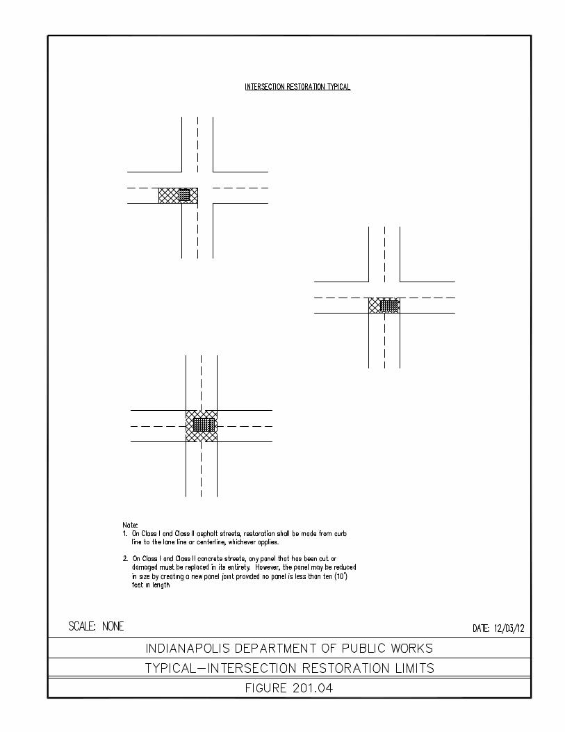


CHAPTER 300 TRAFFIC SIGNAL DESIGN STANDARDS

Chapter 300 3-2 Traffic Signal Design Standards
SECTION 300 Traffic Signal Supplemental Specifications 300.01 The following subsection is a digitally reproduced copy of the City of Indianapolis Introduction Supplemental Specifications to the INDOT 2008 Standard Specifications, and the
January 1, 1998 INDOT Supplemental Specifications (effective date February 15, 1998).
300.02 These Supplemental Specifications are a compilation of revisions to the Indiana Preface Department of Transportation’s 2008 Specifications and the latest INDOT Supplemental
Specifications and are approved by the Director of the City of Indianapolis Department of Public Works. These specifications will be updated every 4 months with effective dates of January 1, May 1, and September 1.
These revisions to the Specifications are accomplished be deleting material from the
specifications and inserting new material. Deletions are usually shown first, followed by new or replacing material. Deletions from the specifications are identified in two ways, either by over-striking the deleted material or by written instructions when the deleted materials are complete paragraphs. New material that is inserted in the specifications is printed in italics.
The written instructions include the section number and the first affect line number.
Such instructions no longer include the specification page number. Line numbers are as referenced in the Standard Specifications.
300.03 SECTION 805, BEGIN LINE 66, DELETE AND INSERT AS FOLLOWS: Salvaged Material Specifications, items shall be stored at a secure site and salvaged by the appropriate
governmental agency. delivered to the City. The Contractor shall be responsible for any damage or loss of this.
Salvaged Material
SECTION 805, BEGIN LINE 125, DELETE AND INSERT AS FOLLOWS: For the use of poles, right of way, or other property incidental to the installation of traffic
signal. Although entering into the contract implies permission and authority to cut into and push
under pavement, sidewalks, and alleys any damage to underground utilities or interruption of such service shall be the responsibility of the Contractor. The Contractor shall be in accordance with 107.11 and 801. The Contractor shall obtain a Right-of-Way Use/Excavation Permit from the City prior to beginning construction.
300.04 Permits
Permits
SECTION 805, BEGIN LINE 1, INSERT NEW SUB-SECTION 805.00 General Conditions For Supplemental Specifications These supplemental
specifications shall be used with the Indiana Department of Transportation (INDOT) Standard Specifications dated 1995, the INDOT Supplemental Specifications, latest edition. In the event these Supplemental Specifications conflict with the INDOT Standard Specifications and Standards or the INDOT Supplemental Specifications, the Indianapolis Supplemental Specifications shall govern
Chapter 300 3-3 Traffic Signal Design Standards
Any reference to the INDOT or the Department shall be construed as to be the Indianapolis Department of Capital Asset Management or Department of Public Works.
Any reference to the Procurement and Distribution Division shall be construes as to be
the City of Indianapolis’ Traffic Engineering Traffic Signal shop at 1735 South West Street, Indianapolis.
300.05 General Conditions
General Conditions
SECTION 922, BEGIN LINE 91, INSERT AS FOLLOWS: The cabinet, controller, and component parts shall be delivered to the Traffic
Engineering Section’s Traffic Signal shop for bench testing at least 21 days prior to the units being required on the job site. The testing will require a maximum of 21 days to complete. If a controller, component or control units fail during the bench test procedures, it may be repaired or replaced by the contractor and retested.
300.06 Controller Bench Testing
Controller Bench Testing
SECTION 922, BEGIN LINE 498, MODIFY AS FOLLOWS: g. Warranty. A standard manufacturer’s warranty shall be furnished for each traffic
signal controller unit which is furnished and installed. The effective date for the beginning of the warranty shall be the turn on date received for bench testing. The warranty shall be provided prior to final acceptance.
Each traffic signal control unit purchased by the Department shall have a minimum 25
year operational warranty or the manufacturer’s standard warranty, whichever is longer. The 25 year warranty shall begin on the date the control unit is received at the Procurement and Distribution Division for bench testing. The vendor or manufacturer
shall be responsible, during the warranty period, for transportation costs to and from the Procurement and Distribution Division Traffic Signal Operations Shop for items requiring warranty service.
Each traffic signal control unit purchased by the Department shall have a 25 year
operational warranty. The 25 year warranty shall begin on the date the control unit passes the Traffic Signal Control Bench Test Procedures.
300.07 Controller Warranty
Controller Warranty
SECTION 922, BEGIN LINE 525, MODIFY AS FOLLOWS: cabinet door on the hinged side, 80 to 100 degrees, and 150 to 180 degrees. The
cabinet stop assembly shall be affixed to the cabinet. The door shall be hinged on the left or right side of the cabinet. The hinge shall be constructed of stainless steel and shall be attached in such a manner that no rivets or bolts are exposed when the cabinet door is in the closed position. All seams shall be sealed with RTV sealant or equivalent material on the interior of the cabinet.

Chapter 300 3-4 Traffic Signal Design Standards
300.08 Controller Cabinet
Controller Cabinet
The cabinet shall have a police door within the main door. The police door shall use a standard Corbin Police panel lock. The police door shall be weather-tight. Two keys shall be furnished for the police door.
In a all cabinets used for a pretimed controller, the police door shall contain 3 separate
switches for control operation, one for automatic or manual, one signal or flash, and one for signal on or off. A 6 mm (1/4 inch) Phone jack receptacle shall be connected to the proper circuits for manual control of any signal interval. The switches shall be protected from water when the door is opened. Located inside the cabinet, easily accessible near the door opening, 2 separate switches shall be installed. One switch for signal or flash operation and one switch for controller stop time/run/stop time/remote operation.
In a cabinet for actuated controllers, the police door shall contain two separate switches,
one switch for master power cut off and one switch to change automatic signal control to flashing control, or vice versa. The switches shall be protected from water when the door is opened.
The cabinet shall contain one duplex convenience outlet and a door-switch controlled
lamp receptacle. The convenience outlet shall be duplex, three-prong, NEMA Type 5-15R grounding outlet in accordance with NEMA WD-6 with ground-fault circuit interruption as defined by the National Electric Code. These units shall be protected with a 15 amp cartridge fuse wired ahead of the multi-breakers. The auxiliary panel shall have a removable front safety cover.
SECTION 922, BEGIN LINE 563, MODIFY AS FOLLOWS: clamp voltage of 350 250 volts at peak current of 20,000 amps for a minimum of 20
occurrences. The voltage shall not exceed 250 colts during surge. Continuous service shall be a maximum of 10 amps at 120 VAC, 60 Hz. The neutral lines, L2 lines and earth grounding from the surge arrestor shall be 10 gauge minimum.
300.09 Controller Surge Protection
Controller Surge Protection
SECTION 922, LINE 589, INSERT THE FOLLOWING: circuits of the flasher controller. Phases 1, 5, 4, and 8 shall be connected to one circuit
and phases 2, 3, 6 and 7 shall be connected on the other circuit for flash operation. The controller back panel shall be fully wired to accommodate the total number of load
switch positions available on the control panel and load switches shall be installed for each position.
300.10 Controller Load Switches
Controller Load Switches
SECTION 922, LINE 639, INSERT THE FOLLOWING: The name of the intersection location shall be centered on the top inside of the cabinet
door. The lettering shall be black silk-screen or lack plastic lettering of a minimum of height of 3/8 inch. A sealable pouch shall be mounted to the inside of the main door. The pouch shall be of sufficient size to accommodate one complete set of cabinet prints.

Chapter 300 3-5 Traffic Signal Design Standards
300.11 Controller Cabinet
Controller Cabinet
The field terminal strip shall be located below the controller panel board. Field terminal strips for all load switch outputs and for pedestrian call inputs shall be sufficient to accommodate copper mechanical lugs for copper wire 6 thru 14 gauge, Panduit part number CB35-36-c, or equivalent, and shall have mentioned lugs affixed to each output to the field and to each pedestrian call input.
Components shall not be wired or located on the backside of any controller back panel
or auxiliary panels and all components shall be accessible with removal of the panel. Test pushbuttons shall be provided for each vehicle phase and each pedestrian phase.
They shall be properly labeled with the appropriate controller phase. The pushbuttons for the vehicle phases shall be capable of extending the associated phase by continuous or intermittent contact. A pre-emption test push button shall be included when a pre-emption sequence is specified.
SECTION 922, BEGIN LINE 881. DELETE AND INSERT AS FOLLOWS: hinged on the right or left side of the cabinet. A Corbin No. 2 standard police door lock
and two No. 2 keys shall be furnished. The lock shall be located near the center of the door on the side opposite the hinge.
300.12 Flasher Controller Cabinet Controller Detection Equipment
Flasher Controller Cabinet Controller Detection Equipment
SECTION 922, BEGIN LINE 916, INSERT AS FOLLOWS: 9. Detection Equipment. The minimum number of and the configuration of the detector
slots shall provide for the following. Two slots shall be wired for power, 8 slots shall be wired for phases and 2 slots shall be wired for use with an emergency vehicle detector system. A means shall be provided to program and assign the detector channels, as required, to service detection needs at the intersection. It shall specifically be possible to assign detectors to serve as local controller in puts of system detector inputs. Provisions shall also be provided to provide a second Detector Card Rack at any intersection.
Four 2 channel inductive loop detector modules shall be provided with each cabinet.
Additional detector modules will be specified in plans or operational specifications. Each 2 channel loop detector shall be a card rack mounted unit; shall be powered from the detector power source; shall have lightning protection as an integral part of the electrical circulatory of the unit; and shall contain two electrically isolated relay output detector channels. The modules shall be compatible with and shall intermate to the Detector Card Rack edge connectors specified in these specifications. Each detector channel shall operate independently of the other channels and shall produce output signals when vehicles pass over or remain with the roadway embedded inductive loop detectors.
Each detector channel shall be of solid-state design; shall perform all frequency
comparison digitally; and shall be based upon a design that shall render detection when a conductive metallic mass (vehicle) enters a inductive loop detector zone of detection and causes a change of 0.02 percent in detector input inductance.
Each 2 channel card-rack-mounted type inductive loop detector module shall conform to
the latest requirements in Section 7 of the NEMA Standards Publication TS-1-1983 for inductive loop detectors (card rack mounted units). Where 2 channel inductive loop detector modules are required to have a time delay feature, the time delay feature shall

Chapter 300 3-6 Traffic Signal Design Standards
be an integral part of the module and shall be adjustable over the minimum range of from 0 to 30 seconds in one second increments-the time delay feature shall operate in such a manner that if 0 seconds is set for a channel, then not time delay shall apply to the channel.
Each detector channel output shall be relay output controlled. Electrical connections for each 2 channel inductive loop detector module shall be made
by a 22-pin double read-out edge connector which shall mate with the edge connector mounted on the detector card rack specified in these specifications.
SECTION 922, BEGIN LINE 1006, DELETE AND INSERT AS FOLLOWS: on the hinged side shall be attached with hinge pins. Each lens shall have the standard
cap tunnel type visor, unless otherwise specified. Visors must be attachable with at least four screws.
SECTION 922, BEGIN LINE 1248, DELETE SECTION 913.15 (d)4 AND INSERT AS
FOLLOWS: The minimum design requirements for light lamps to be used in a traffic signal face shall
be as set out in the ITE (Institute of Transportation Engineers) standard for traffic signal lamps and as follows:
300.13 Traffic Signal Lamps
Traffic Signal Lamps
SECTION 922, BEGIN LINE 1518, DELETE AS FOLLOWS: pole shall be steel or aluminum. Steel poles shall be in accordance with ASTM A 595 or
A 572 with a minimum yield strength of 345 kPa (50,000 lb.) and shall be galvanized in accordance with ASTM A 123. Aluminum poles shall be in accordance with ASTM B 221 M (astm B 221) and ASTM B 241 M (ASTM B 241), alloy 6063-T6, or in accordance with ASTM B221 M (ASTM B 221), alloy 6005-T5.
(4) Hardware. All hardware for steel poles except boles for the mast arm clamps and
anchor bolts shall be in accordance with ASTM A 307 and shall be galvanized in accordance with ASTM A 153 or be mechanically galvanized and conform to coating thickness, adherence, and quality requirements of ASTM A 153. A cast pole cap shall be in accordance with ASTM A 126 and shall be galvanized with a minimum coating of 0.610 kg/m (2oz/ft)
300.14 Traffic Signal Mast Arms
Traffic Signal Mast Arms
All hardware for aluminum poles shall be stainless steel in accordance with ASTM A 276, type 304 or type 305.
SECTION 922, BEGIN LINE 1576, DELETE AS FOLLOWS: length prior to galvanizing.
300.15 Traffic Shop Drawings
Traffic Shop Drawings

Chapter 300 3-7 Traffic Signal Design Standards
SECTION 922, BEGIN LINE 1612, DELETE AND INSERT AS FOLLOWS: calculations shall be submitted to the Division of Design Project Manager for approval.
A copy of the transmittal letter shall be sent to the Engineer. The approved drawings will be distributed by the Division of Design Project Manager.
300.16 Traffic Signal Loop Sealant
Traffic Signal Loop Sealant
SECTION 922, BEGIN LINE 1770, INSERT AS FOLLOWS: shall be sealed with steep roof pitch or a joint sealer material in accordance with
906.02(a) 1 or 906.02(a) 2. SECTION 913, BEGIN LINE 4466, INSERT AS FOLLOWS:
Chapter 300 3-8 Traffic Signal Design Standards
Copper. “Football” type mechanical clamps of the correct size and installed to provide a satisfactory grounding connection shall be acceptable.
301.00 TRAFFIC SIGNAL STANDARD FIGURES Traffic Signal Standard Figures
301.01 Controller Cabinet Foundation Type P-1 301.02 Controller Cabinet Foundation Type M 301.03 Signal Pedestal Foundation Type A 301.04 Signal Handhole 301.05 Ring and Covers 301.06 Modified M to P-1 Foundation 301.07 Modified A to M Foundation 301.08 Modified A to P-1 Foundation 301.09 Signal Service & Controller on Wood Pole 301.10 Signal Service & Controller on Steel Pole 301.11 Signal Service on Wood 301.12 Signal Service on Wood Pole 301.13 Signal Indication Mounted on Steel or Wood Pole 301.14 Pedestal Mounted Signal Indication 301.15 Controller (G Cabinet) on Pedestal 301.16 Underground Service on Pedestal 301.17 Detector Housing Installation 301.18 Detector Housing 301.19 Detector Housing Adaptor 301.20 Traffic Signal Loop Installation 301.21 Traffic Signal Loop Installation 301.22 Traffic Signal Detector Housing Installation 301.23 Traffic Signal Loop Splice 301.24 Traffic Signal Loop Cabinet Connection 301.25 Loop Tagging System 301.26 Signal Mast Arm 301.27 Signal Mast Arm Details 301.28 Signal Mast Arm Foundation

Chapter 300 3-9 Traffic Signal Design Standards
301.29 Signal Mast Arm Details 301.30 Signal Mast Arm Data and Notes 301.31 Signal Pedestal Base and Anchor Bolts 301.32 Strain Pole Alignment 301.33 Strain Pole Foundation 301.34 Cabin Span Attachment 301.35 Span, Catenary & Tether Details 301.36 Side Mounted Signal on Steel Pole 301.37 Steel Strain Pole 301.38 Strain Pole Details 301.39 Strain Pole Band Details 301.40 Strain Pole Base Plate Details 301.41 Strain Pole Anchor Bolt Details


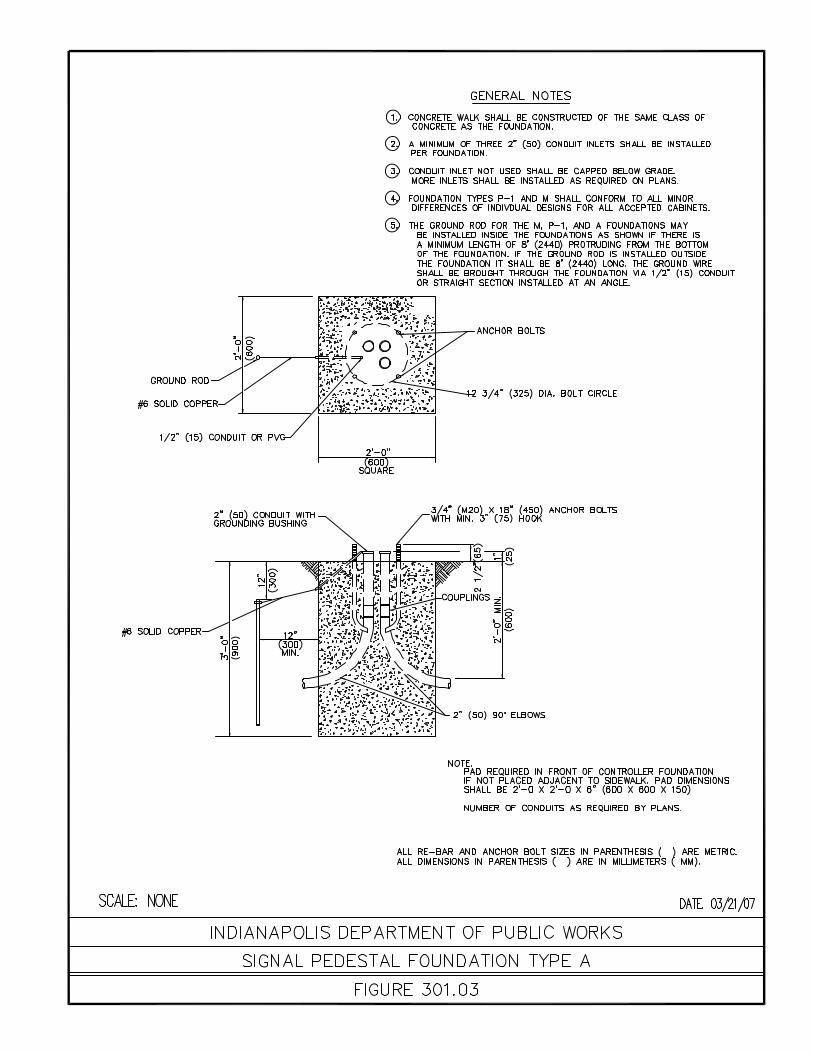

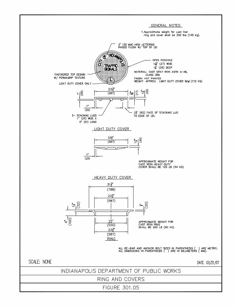


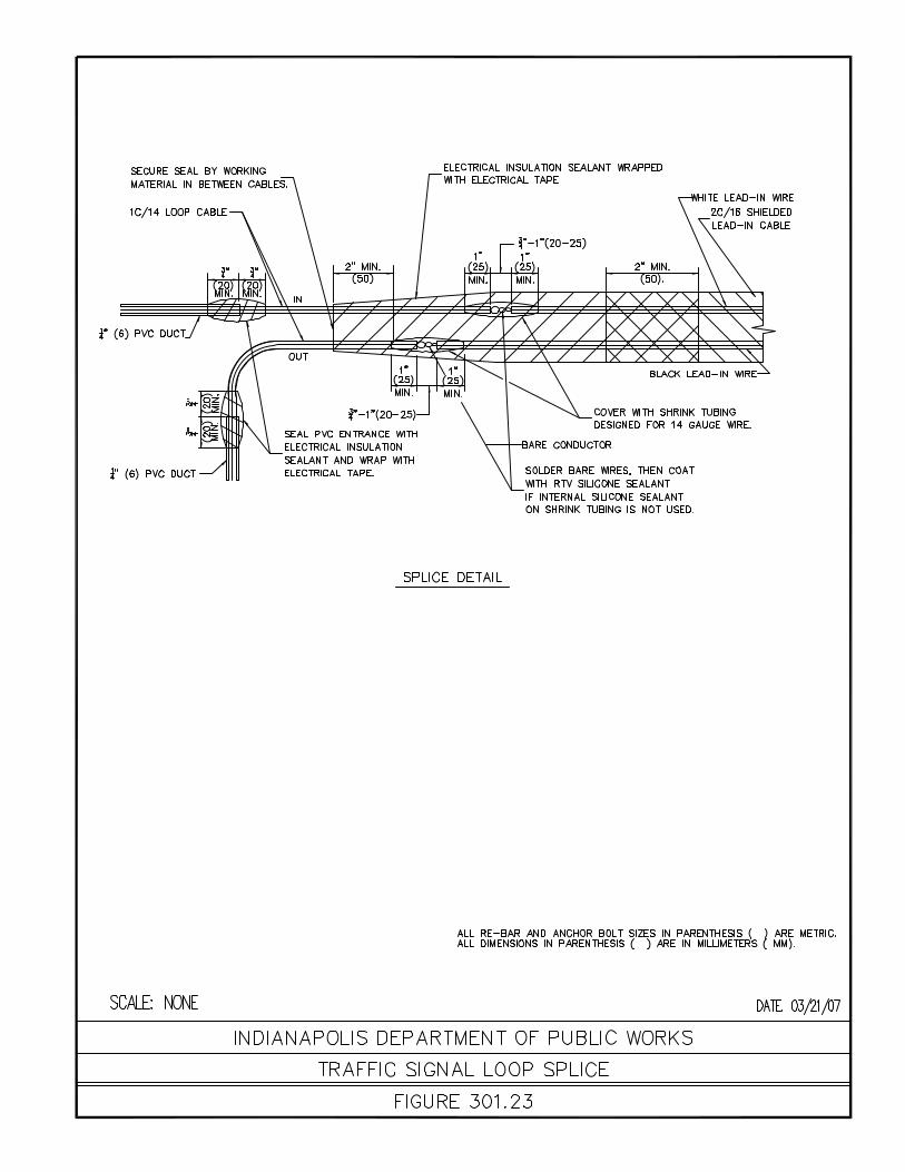


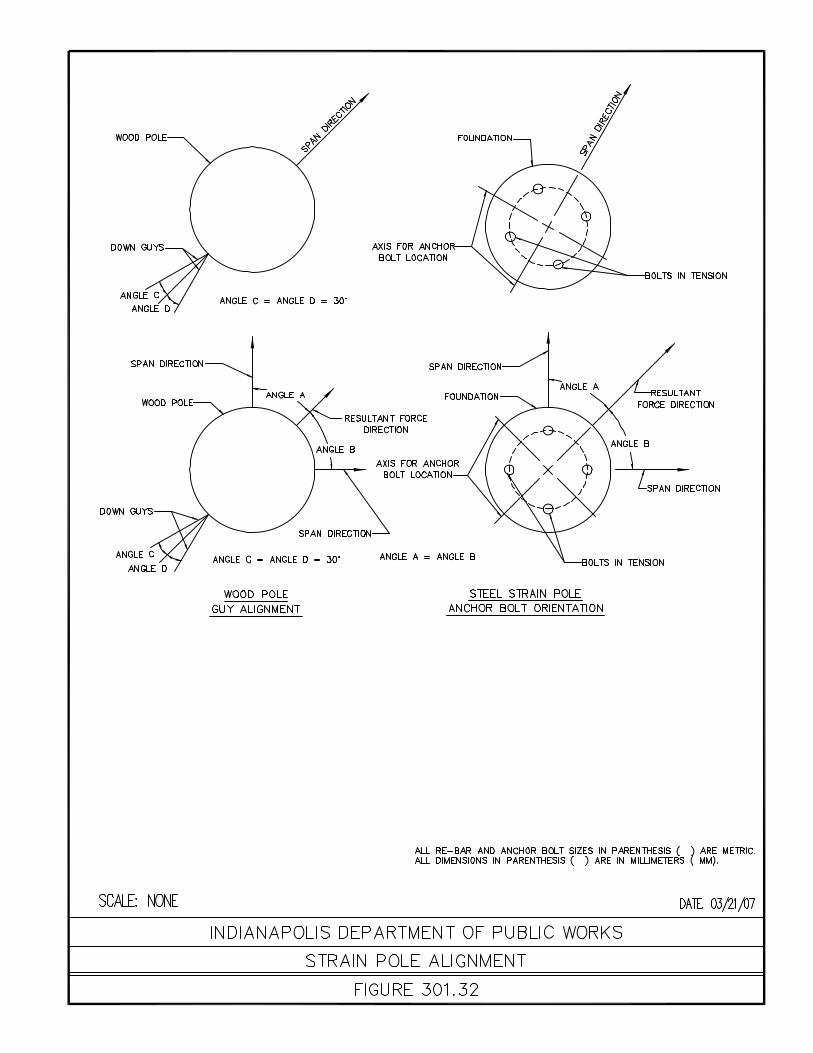


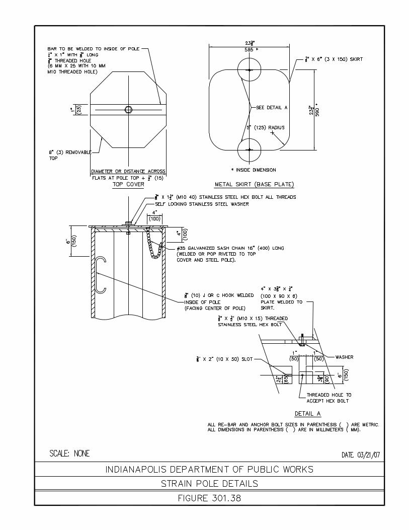


CHAPTER 400
CONCRETE CURB RAMPS

Chapter 400 4-2 Concrete Curb Ramps
CHAPTER 400 Concrete Curb Ramps
400.01 The following chapter covers the use of curb ramps with in the jurisdiction of the City of Introduction Indianapolis Department of Public Works. Information contained in this chapter is from
INDOT Standard Drawings and The Indiana Design Manual. The Indiana Design Manual information has been revised to meet DPW’s standards. The revisions are shown as a striking out of material that does not pertain to DPW.
400.02 This section is from the Indiana Design Manual, Section 51-1.08 Concrete Curb Concrete Curb Ramps Ramps A project which includes curbs and sidewalks at pedestrian crosswalks will require
sidewalk curb ramps to eliminate physical barriers for ease of access to such crosswalks. A pedestrian crosswalk is defined as the portion of a street ordinarily included within the prolongation or connection of lateral lines of sidewalks at an intersection. It also includes any portion of a highway or street distinctly indicated as a crossing for pedestrians by means of lines or other markings on the pavement surface.
A curb ramp provides a sloped area within a public sidewalk that allows pedestrians to
accomplish a change from sidewalk level to street level. A curb ramp typically includes the ramp and flared sides and specific surface treatments, but does not include the landings at the top and bottom of the ramp.
Curb ramps are to be placed at all crosswalks which extend from a paved sidewalk in
each intersection with a curbed public roadway or curbed signalized commercial drive. Curb ramps should not be used at private drives, alleys, or unsignalized commercial drives. Instead, a sidewalk elevation transition as shown on the INDOT Standard Drawings should be placed. At a T-intersection, the designer should ensure that curb ramps are located on the side opposite the minor intersecting road if a sidewalk is present or is to be provided.
For a partial 3R project, curb ramps should be considered as described in Chapter Fifty-
six. Curb ramps should not be considered for a signing, pavement marking, or roadway lighting project.
400.03 This section is from the Indiana Design Manual, Section 51-1.08(01) Location. Location When determining the locations of curb ramps, the designer should consider the
following: 1. Curb ramps should be located directly opposite one another for each crosswalk,
and should be laced within the transverse limits of crosswalk lines, where crosswalk lines are used.
The placement of curb ramps affects the placement of crosswalk lines and
vehicle stop lines. Conversely, the location of existing crosswalk lines and stop lines affect the placement of curb ramps. Some of the crosswalk-line constraints are shown in figure 51-1F, Types of Curb Ramps at Marked Crossings, and in the INDOT Standard Drawings. The Manual on Uniform Traffic Control Devices contains additional constraints on crosswalk- and stop-line placement.
2. Each ramp should be designed and placed to provide continuity of the sidewalk
corridor direction of travel while providing pedestrians the shortest but most direct route across a street.
3. The designer should ensure that the landing area at the bottom of each curb
ramp does not encroach upon through-lane vehicle traffic which has the right-of-
Chapter 400 4-3 Concrete Curb Ramps
way at the same time a pedestrian is attempting to use the crosswalk parallel to it.
4. The curb ramp and associated landings should not be compromised by other
highway features (e.g., guardrail, catch basins, utility poles, fire hydrants, sign or signal supports, etc.).
5. There should be full continuity of use throughout. Opposing curb ramps should
always be provided in all required intersection quadrants, including intersections with some quadrants outside the project limits.
6. Curb ramps should be located or protected to prevent their obstruction by parked
vehicles. 7. Approval of a Level One waiver of the accessibility requirements for physically
impaired individuals is required for each location where there are valid reasons to restrict or prohibit pedestrian access. Such waiver is described in Section 40-8.04(01) Item 2.
8. The normal gutter flow line should be maintained through the curb ramp area.
Appropriate drainage structures should be placed as needed to intercept the flow prior to the curb ramp area. Positive drainage should be provided to carry water away from the intersection of the curb ramp and the gutter line, thus minimizing the depth of any flow across the crosswalk.
9. If modifications to the details shown on the INDOT Standard Drawings are
required so that a curb ramp can be better accommodated, such details and the required pay quantities should be shown on the plans.
10. The impact of utilities location on curb-ramp placement and construction should
be minimized. The designer is responsible for being aware of potential utility conflicts. If utilities are present, coordination should be in accordance with Section 10-2.0.
400.04 This section is from the Indiana Design Manual, Section 51-1.08(02) Types of Sidewalk Curb Ramps Details for placement of curb ramps and an illustration showing appropriate locations for
all curb ramp types are shown on the INDOT Standard Drawings. Determining which curb ramp is most appropriate depends on the exact conditions of the site. Curb ramps are categorized below by their structural design and how they are positioned to the sidewalk or street.
1. Perpendicular Curb Ramp. This curb ramp is perpendicular to the curb and
requires a wide enough sidewalk to provide a 12:1 running slope. This is the preferred design. The length of the ramp depends on the height of the curb
where the ramp is to be located. Details of a ramp with an integral curb and of a ramp with a separate curb are shown on the INDOT Standard Drawings. A landing should be provided at the top of the ramp. If site infeasibility precludes construction as shown on the INDOT Standard Drawings, the level landing width
may be decreased from 4 ft. to 3 ft., and the running slope may be increased to 10:1 for a maximum 6 in. rise. New construction should always provide adequate right-of-way for a perpendicular curb ramp. Some portion of the curb ramp, typically one of the flared sides, may fall within the curved intersection corner. See the INDOT Standard Drawings for details of improved access to perpendicular curb ramps.
The standard perpendicular curb ramps are as follows: a. Type A. This type should be specified where a curb ramp is required
entirely within the pedestrian walkway. It is the preferred type where the sidewalk is adjacent to the curb.

Chapter 400 4-4 Concrete Curb Ramps
b. Type C. This type should be specified where a curb ramp is required
outside the pedestrian walkway, in the utility strip. It is the preferred type where there is a utility strip between the sidewalk and the curb.
c. Type D. This type should be specified where a curb ramp is required near
an obstruction which can not be removed. It is the preferred type for this situation, and may be used with or without a utility strip present.
2. Diagonal Curb Ramp. A diagonal curb ramp is a single curb ramp that is located
at the apex of the corner at an intersection, and serves two intersecting crossing directions. Since the ramp is diagonal to the path of travel, it is only accessible if level landing or maneuvering spaces are provided at both the tope and bottom of the ramp. If creating a level landing is too difficult or a 4-ft. clear space cannot be provided, a diagonal curb ramp should not be considered. If site infeasibility precludes construction as shown on the INDOT Standard Drawings, the landing width may be decreased from 4 ft. to 3 ft. and the running slope may be increased to 10:1 for a maximum 6 in. rise.
A diagonal curb ramp should only be used where perpendicular or parallel curb
ramps are infeasible and no other option is available, or if a field investigation warrants its use for alterations affecting existing sidewalks.
If diagonal curb ramps are to be used, durable crosswalk markings are required
on the street pavement. Specific constraints for crosswalk markings and stop-lines placement are shown on Figure 51-1F, Types of Curb Ramps at Marked Crossings. Each diagonal curb ramp should be wholly contained within the crosswalk lines, including any flared sides. There should be at least 4 ft. between the gutter line and the corner of the two intersecting crosswalk lines as delineated within the intersection pavement area. See Figure 51-1F for an illustration of these criteria.
The standard diagonal curb ramps are as follows: a. Type B. This type should be specified where a curb ramp is required
entirely within the pedestrian walkway, the corner radius is greater than 10 ft., and placement of a Type A ramp is infeasible. At the bottom of the ramp, the perimeter length is 8 ft., regardless of the corner radius.
b. Type E. This type should be specified where a curb ramp is required
outside the pedestrian walkway in the utility strip, the corner radius is greater than 10 ft., and placement of a Type B ramp is infeasible.
This type should also be specified where a curb ramp is required outside
the pedestrian walkway in the utility strip, the corner radius is greater than 10 ft., an obstruction which cannot be removed is present, and placement of a Type C ramp is infeasible.
At the bottom of the ramp, the perimeter length is 8 ft., regardless of the
corner radius. 3. Parallel Curb Ramp. A parallel curb ramp has two ramps leading down towards
a center level landing at the bottom between both ramps and has level landings at the top of each ramp. A parallel curb ramp may be specified for a narrow sidewalk, steep terrain, or at a location with a high curb, as the ramp can easily be lengthened to reduce the grades. A parallel curb ramp should not be installed where it is possible to install two perpendicular curb ramps. A wall or curb may be required along the back edge of the ramp as shown on the INDOT Standard Drawings. The designer should show details for such wall or curb on the plans and include a unique special provision.

Chapter 400 4-5 Concrete Curb Ramps
Parallel curb ramps should only be used where perpendicular curb ramps are infeasible and no other option is available.
The standard parallel curb ramp is Type F. This type should be specified where
the corner radius at least 15 ft. but less than 25 ft., and only if a field investigation warrants its use for alterations affecting existing sidewalks.
4. Depressed-Corners Curb Ramp. Depressed corners gradually lower the level of
the sidewalk to meet the grade of the road, street, or signalized approach. This curb ramp should be specified only at a corner where the sidewalk parallels only one of the intersecting roadways.
The standard depressed-corners curb ramps are as follows: a. Type H. This type should be specified where the sidewalk is adjacent to
the curb. b. Type G. This type should be specified where there is a utility strip between
the sidewalk and the curb. 5. Mid-Block Curb Ramp, Type K. This type should be specified at a mid-block
location. It may be used where the sidewalk is adjacent to the curb or where there is a utility strip between the sidewalk and the curb approved of DPW.
6. Median Curb Ramp, Type L. This type should be specified where a raised paved
or unpaved median of 8 ft. or greater width obstructs the crosswalk. Where the median width is less than 8 ft., a detail should be shown on the plans.
400.05 This section is from the Indiana Design Manual, Section 51-1.08(03) Selection Guidelines The following provides guidelines for selecting the appropriate curb ramp. 1. Sidewalk and Utility-Strip Widths. The INDOT Standard Drawings show
minimum sidewalk widths and utility-strip widths. These minimum widths are intended for new construction and reconstruction, typically to construct perpendicular curb ramps. Parallel curb ramp type F may be used where an existing sidewalk cannot be widened to the minimum width.
2. Obstructions. It is desirable to move an obstruction wherever practical. Where it
is not practical to move the obstruction, the direction of traffic relative to the placement of the curb ramp should be considered. It is important that drivers can see a physically impaired person using the curb ramp. Where obstructions are present, such as signal controller boxes, planters, signal pole bases, etc., a perpendicular curb ramp Type D should be used. No obstruction should be permitted within flared sides which are paved.
3. Best Practices. The following should be considered. a. A level maneuvering area or landing should be provided at the top of each
curb ramp. b. The ramp slope should be perpendicular to the curb, with a maximum of
8.33%. Details regarding curb ramp slopes are shown on the INDOT Standard Drawings.
c. The counterslope of the gutter area or street at the flat of a curb ramp
should be a minimum of 20:1. d. Curb-ramp geometrics to be used are summarized in Figure 51-1G.

Chapter 400 4-6 Concrete Curb Ramps
400.06 This section is from the Indiana Design Manual Sections 51-1.08(04) and 51-1.08(05) Curb Ramp Lengths and Slopes Curb ramps should be designed with a maximum slope of 12:1, or 8.33%. See Figure
51-1H, Lengths of Perpendicular Curb Ramps, to determine the length of a curb ramp which is perpendicular to the curb. The figure assumes a 2% sidewalk cross slope and a level longitudinal grade.
For a curb ramp which is not perpendicular to the curb, the following formula should be
used to determine its length. The formula assumes a 2% sidewalk cross slope and a level longitudinal grade.
LCR = h [Equation 51-1.1] Cosθ (GR – GS) Where: LCR = Curb ramp length, ft. H = Change in elevation, ft. GR = Curb ramp grade, % / 100 GS = Sidewalk cross grade, % / 100 θ = Angle to which the curb ramp is out of perpendicular to the curb. The algebraic difference between a curb ramp slope and the gutter or pavement slope
should be less than 11%. If this is not possible, a 2-ft. wide level strip should be provided between the grades. See the INDOT Standard Drawings.
ΔG - │GR - GG│ [Equation 51-1.2] GR = Ramp grade, % GG = Gutter grade, % │GR - GG│ = Absolute value of grade difference, %
A level strip is required if ΔG 11%.
400.07 This section is from the Indiana Design Manual, Section 51-1.08(06) Detectable Warning Devices Each sidewalk curb ramp is to include a detectable warning device. This consists of a
standardized surface feature to warn people with vision impairments that they are approaching a street or driveway. The color and texture of the device must contrast visually with adjoining surfaces. Details and explanations are shown on the INDOT Standard Drawings and the INDOT Standard Specifications, respectively.
400.08 This section is from the Indiana Design Manual, Section 51-1.08(07) Pedestrian Signal Controls If a pedestrian crosswalk and curb ramp are present at an intersection with a traffic
signal that has pedestrian-signal-activating pushbuttons, the following will apply. 1. Location. Pushbutton controls should be located as close as practical to the curb
ramp and, to the maximum extent feasible, should permit operation from a level area immediately adjacent to the controls. Controls should be placed so as not to create an obstruction to the curb ramp.

Chapter 400 4-7 Concrete Curb Ramps
2. Surface. A sidewalk area of 4 ft. by 4 ft. should be provided to allow a forward or parallel approach to the controls. In a restricted area, such sidewalk area may be reduced to 3 ft. by 3 ft.
401.00 CURB RAMP STANDARD FIGURES Curb Ramp Standard Figures
401.01 Intersection Showing Typical Curb Ramps And Inlet Locations
401.02 Roll Curb & Gutter Depressed Curb Detail

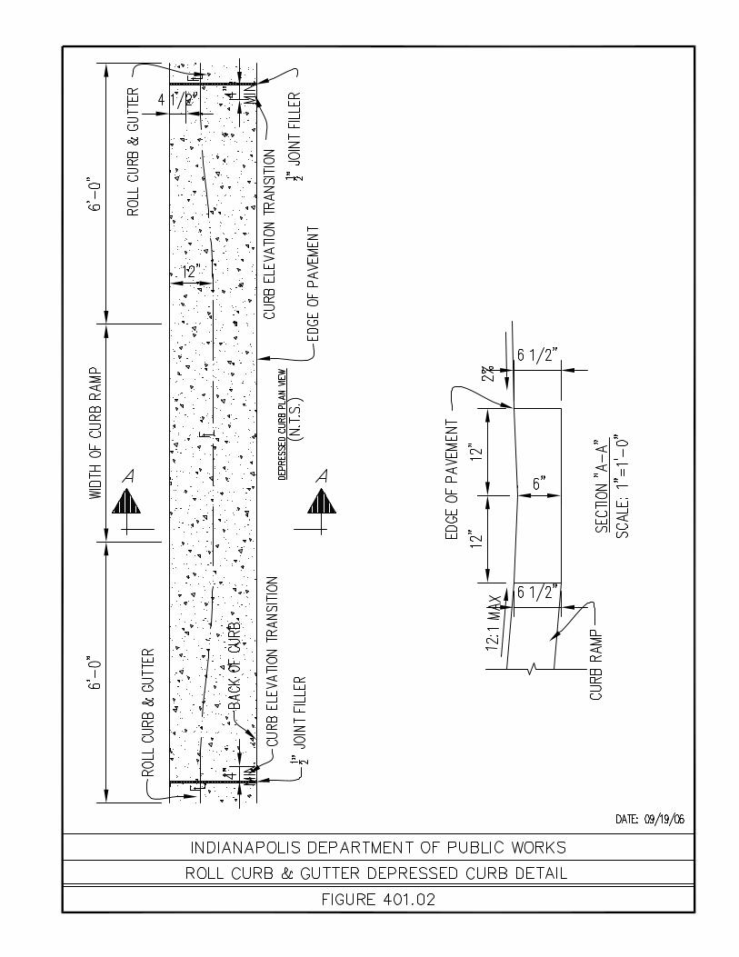
CHAPTER 500
BICYCLE FACILITY STANDARDS

Chapter 500 5-2 Shared Bicycle Facility Standards
CHAPTER 500 Shared Bicycle Facility Standards
500.01 The following chapter covers the use of shared bicycle facilities within the Introduction jurisdiction of the City of Indianapolis Department of Public Works. These standards are
based on the National Association of City Transportation Officials (NACTO), Urban Bikeway Design Guide.
Other reference material used to establish these standards are AASHTO manual “Guide
for the Development of Bicycle Facilities” Dated 2012 and Manual on Uniform Traffic Control Devices.
These standards are guidelines for the use of shared bicycle facilities and are not meant
to be an all inclusive design for all situations. It is the designer’s responsibility to provide a design that provides a safe condition for both bicycle and motorized vehicular traffic.
500.02 Shared Bicycle Facility is the use of roadway to be shared by both bicycles and
Terms motorized vehicular traffic. Shared Roadway is a roadway that has sufficient width for safe bicycle traffic, but is not
designated in any manor. Signed Shared Roadway is a roadway that has sufficient width for safe bicycle traffic and
is signed and designated as a bike route. Bicycle Lane is a roadway that has pavement marking that designate a travel lane for
bicycle traffic. Sharrow is the term used to describe the pavement marking for a shared use facility. It
consists of a double chevron and bicycle symbol.
500.03 Bicycle lane shall have a minimum width of five (5’) feet from the edge of the motorized General Design traffic lane and face of curb or other obstruction (i.e. guardrail). Of the five (5’) foot Bicycle
lane width, there shall be a minimum of three feet, six inches (3’-6”) free of any open drainage structures.
When an open drainage structure encroaches within the 5 (5’) foot dimension, it shall have
a bicycle-safe grating. When a bicycle lane is between a motorized travel lane and curb, there shall be a eight
(8”) inch solid white lane line placed. When a Bicycle lane is between a motorized travel lane and parking spaces, there shall be a six (6”) inch solid white lane line placed between the motorized travel lane and the bicycle lane, and a four (4”) inch solid white lane line between the bicycle lane and parking spaces. When a shared roadway or signed shared roadway is utilized, the outside motorized lane width shall be fourteen (14’) foot minimum and sixteen (16’) foot maximum.

CHAPTER 600 ACCESS CONTROL MANUAL

Chapter 600 6-2 Access Control Manual
CHAPTER 600 Access Control Manual
600.01 The following chapter is a digitally reproduced copy of the Access Control Manual Introduction dated July, 1975. The Access Control Manual regulates the location, design, permitting and operation of
driveways and approaches within the City of Indianapolis, Indiana and Marion County, Indiana.
The purpose of this manual is to supply the Engineer, Architect, Surveyor, Planner,
Developer or Property Owner the necessary regulation for the location, design and operation of driveways and approaches, so that the interference to through traffic is minimized.
The City of Indianapolis Department of Public Works (DPW) by law (1) has jurisdiction
over all thoroughfares in Marion County, except those roads which are under the jurisdiction of the Indiana Department Of Highways (INDOT), and according to law, the DPW has the power to plan, design, construct and operate all roads designated as thoroughfares by the Department of Metropolitan Development of Marion County. The DPW by intergovernmental agreement (2) with the City of Indianapolis also traffic control on all streets inside the corporate boundaries of Indianapolis. This Agreement among other powers, gives the DPW the power to approve all driveway permits in the City. Therefore, in order to properly operate these streets a definite policy on ACCESS CONTROL has been developed.
Any materials of this magnitude must be continually updated because of the rapid
changes in design standards, safety standards and planning ideas which relate to driveway regulations, therefore, the DPW and all other agencies directly or indirectly involved in regulating driveways and approaches must coordinate their efforts in obtaining a high level of control for driveways and approaches in Marion County.
l 600.02 Any person who owns property adjoining a street or sidewalk, the surface of which Protection of Lots property close to any part of the street or sidewalk is lower than the street so as to make Below Street Grade a dangerous offset, shall guard and enclose the lot securely on the side next to the
street so as to prevent danger to persons passing along street. It shall be the duty of the chief of the metropolitan law enforcement agency, or other city officials charged with such duty, to cause written notice to be given to any person subject to this section to comply with this section within a reasonable time, not less than ten (10) days, and any person failing to do so within five (5) days after the expiration of the time fixed by the notice or as extended by the board of public works shall be guilty of a violation.
600.03 The Thoroughfare System shows four classifications – freeways, expressways, primary Thoroughfare System arterials, and secondary arterials. Collector routes and local routes are not shown on
the map. This Plan has been prepared as part of Indianapolis Regional Transportation and Development Study for the future urbanized area of the Department of Metropolitan Development.
Once it has been determined which type of road the Developer is encroaching on, he
can then refer to Subsection 600.04 for the necessary driveway standards.
600.04 Included on the following pages are the most common examples of driveways and Driveway Standards approaches. These standards will apply in majority of cases because many
combinations can be derived from each figure. However, there will be exceptional situations and borderline cases where the standards and guides do not apply. In such instances, interim standards will be used. The next lowest functional type (i.e. the interim dimensions for arterials are the dimensions for collectors). The use of interim

Chapter 600 6-3 Access Control Manual
dimensions will be subject to the approval of the Traffic Engineer and such approval should precede the actual filing of permit application.
Additional standards which will be required are as follows: 1. ENTRANCE AND EXIT ONLY DRIVEWAYS. This type of driveway is not highly
recommended for a divided roadway. However, the entrance and exit driveways do have a purpose and when warranted use the following dimensions:
Minimum width = 17 feet Maximum width = 24 feet In order to control entrance and exit drives they must be properly signed. This is
the responsibility of the property owner. 2. NUMBER OF DRIVEWAYS AND SPACING. Driveway spacing is largely
dependant on land use and zoning, as a result, it is difficult to develop definite standards. Although from past experience and a literature review on this subject, not more than two driveways are generally needed to serve a tract of land. Additional policies are as follows:
a. Expressways – Not applicable b. Arterials – frontage roads are encouraged but where this is not feasible a
minimum spacing of 150 feet is required between adjacent property owners. Also, as a general rule if the frontage is 100 feet or less, only one driveway will be permitted.
c. Collectors – a minimum spacing of 100 feet is required and generally only
one driveway per 100 foot of frontage will be allowed.
600.05 Listed below are the plot plan requirements which must be met before commercial Plot Plan Specifications driveway permit applications can be accepted for review. 1. Applicant must submit four (4) copies of plot plan 2. The plot plan must be certified by registered Professional Engineer, Architect or
Land Surveyor. 3. A vicinity sketch must be shown on the plot plan at a scale of not less than 1” =
2000’, and must indicate the location of said property to major arterial streets, railroads, etc.
4. Standard engineering scales (i.e. 1” = 20’, 1” = 30’) must be used. 5. Use of each access point must be specified – entrance only, exit only, entrance
and exit. 6. Adequate description of proposed use of property must be included. 7. The plan must show the width of existing and adjacent driveways, streets, alleys
and right-of-way 150 feet beyond property lines on both sides of the street, plus the plan must show the location of all utilities and any other pertinent topography.
8. Location and geometrics of proposed access points, and location and size of
existing or proposed building must be shown. 9. Location and details of permanent signs must be shown. 10. Cross sections for pavement widening and curbs must be illustrated, if
applicable.

Chapter 600 6-4 Access Control Manual
11. The plot plan must include proposed parking arrangement with anticipated
number of vehicles. 12. Plot plan must show all existing and proposed drainage structures, including
pipe, catch basins, head walls, etc., necessary to provide adequate drainage.
600.06 Permit forms may be obtained and filed at the Permit Desk, Room 2321, City-County Permit Procedures Building. On State Highways, the Indiana Department Of Highways must also approve
the driveway. The following procedures must be followed for all commercial driveway permits. CASE I If the site is properly zoned, the developer must obtain commercial
driveway permit before an Improvement Location Permit and Building Permit will be given final approval.
1. Obtain and file application and four (4) copies of plot plan with appropriate
agency (city, state). Application must be complete and plot plan must meet all specifications before it will be accepted.
2. If driveway permit application and plat plan are acceptable the agency will
transmit copies of the application and the plot plan to the DPW, TRAFFIC ENGINEERING DIVISION.
3. After the plot plan has been processed and if approved with only minor revisions,
the application will be processed for approval. 4. If major changes are necessary, the plot plan will be returned to the applicant.
Applicant may then resubmit revised plot plan to the Traffic Engineer if acceptable, he will then process the same as mentioned above.
CASE II If a Variance or Re-zoning is required, the developer must obtain these
before driveway approval can be obtained.
CHAPTER 700
COMMERCIAL DRIVES
Chapter 700 7-2 Commercial Drives
SECTION 700 Introduction
700.01 This chapter provides information for the design and construction of commercial drives Introduction and approaches within the jurisdiction of the City of Indianapolis Department of Public
Works. This information is a minimum standard and it is the responsibility of the designer to design for the conditions that are expected at the site being developed.
700.02 Minimum commercial drive width shall be thirty six (36’) feet from edge to edge of drive Commercial Drive Width within the public Right-Of-Way. This will allow one ingress movement and two egress
movements (one left and one right) with all lanes being twelve (12’) feet in width. Depending on the site being developed and existing roadway conditions, additional
turning movements may be required. A traffic study may be needed to determine if additional lanes are needed. If additional lanes are required, they shall have a minimum width of twelve (12’) feet.
700.03 Minimum curve return radius for commercial drives shall be twenty (20’) feet. Commercial Drive Curve Return Radius Depending on traffic study and the size of vehicles accessing the developed site, a
greater radius may be required. The designer shall evaluate the site and design the commercial drive to allow turning of the largest vehicle expected to access the development.
700.04 An auxiliary lane is required in an urban area where there are inadequate lanes Auxiliary Lane available for safe ingress or egress movement of traffic, or if speed of thoroughfare
causes an unsafe condition.
700.05 Acceleration, deceleration and passing blisters will be required if traffic volumes dictate Acceleration, Deceleration the need to provide safe ingress or egress of traffic And Passing Blister Lanes
700.06 All commercial drives shall have Combined Concrete Curb and Gutter (Type II) when Concrete Curb adjacent to new thoroughfare construction. If a commercial drive is connecting to an
existing thoroughfare, the commercial drive’s curb shall match the existing street curb.
700.07 When a commercial drives is being constructed where there are existing or proposed Concrete Curb Ramps sidewalks adjacent to the thoroughfare, the appropriate concrete curb ramp shall be
constructed. For concrete curb ramp requirements, see Chapter 400 of this manual.
700.08 Within the public Right-Of-Way, commercial drives and approaches shall have the same Material material and thickness as the adjacent thoroughfare. See Section 100.06 of this manual
for the minimum thickness requirements based on street classification. When auxiliary lanes, acceleration, deceleration and passing blisters are required, they
shall have the same material and thickness as the adjacent thoroughfare.
700.09 Permit procedure for all commercial drives shall be in accordance with Section 600.06 Permitting of this manual.

Chapter 700 7-3 Commercial Drives
SECTION 701 Commercial Drive Standard Figures
701.01 Minimum Commercial Drive Geometrics
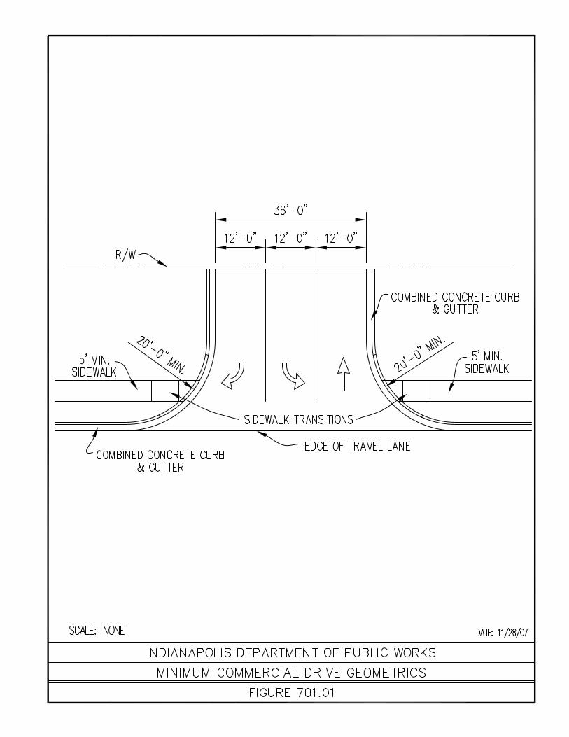

CHAPTER 800 NEIGHBORHOOD TRAFFIC CALMING

Chapter 800 8-2 Neighborhood Traffic Calming
CHAPTER 800 Neighborhood Traffic Calming
800.01 The purpose of this document is to set forth the recommended practices in planning, Purpose designing and constructing neighborhood traffic calming devices throughout the City of
Indianapolis, Indiana. Likewise, it is important to establish the following definition of traffic calming (this definition was derived by the subcommittee on Traffic Calming of the Institute of Transportation Engineers in 1997):
“Traffic Calming is the combination of mainly physical measures that
reduce the negative effects of motor vehicle use, alter driver behavior and improve conditions for non-motorized street users.”
The primary objective of traffic calming is to create safer roads and a better quality of life
for the neighborhoods that we live in. The strategic objectives are: To improve driver behavior, concentration, and awareness, To reduce speed To reduce cut-through traffic To improve safety for pedestrians, bicycles, and vehicles, and To enhance the quality of life, and improve aesthetics These recommended practices provide the consistency needed in reviewing these
requests. The practices identified herein have been obtained from various references on traffic calming including the following: “Guidelines for the Design and Application of Speed Humps”, prepared by ITE Technical Council Speed Humps Task Force; “Traffic Calming in Practice”, prepared by County Surveyors Society, Department of Transport, Association of Metropolitan District Engineers, Association of London Borough Engineers and Surveyors, Association of Chief Technical Officers; “Traffic Calming”, American Planning Association, Planning Advisory Service Report Number 456; “The Traffic Safety Toolbox, a Primer on Traffic Safety”, Institute of Transportation Engineers, “Traffic Calming Primer”, Pat Noyes and Associates, and “Canadian Guide to Neighborhood Traffic Calming”, Transportation Association of Canada.
The following is a brief outline of the elements contained in the process for investigating
the need for neighborhood traffic calming. Also included in this document is a list of alternative traffic calming measure which describes the measure, and the conditions and circumstances for their use. This document will also be incorporated in the City of Indianapolis Street Standards for new subdivisions.
800.02 Appropriate neighborhood traffic control devices should only be installed to address Planning documented safety or traffic concerns supported by traffic engineering studies. These
studies will include an examination of the full array of potential improvement actions beginning with a recommendation to law officials for better enforcement of existing controls. The City’s Traffic Engineering staff will use the following procedures in order to determine the need for traffic calming for each neighborhood request. Data will be collected and analyzed by the City staff, and the data will be compared with established criteria to determine if the location is eligible for consideration, and findings and conclusions will be documented in a formal report.
Citizen Support Traffic Advisory Committee Street Classification Traffic Volumes Traffic Speeds Geometric Data Accident History Public Safety Agencies Input Alternative Traffic Calming Measures Implementation Plan

Chapter 800 8-3 Neighborhood Traffic Calming
Final Report Approval Evaluation Plan 1. Citizen Support Before any neighborhood traffic calming devices can be installed, 75 percent of
the residents directly affected by the installation of the device should be in support of the action. If the neighborhood has an association, they too should
support the request. After the investigation is complete, all potentially affected residents will be invited to information meetings, and will have an opportunity to provide input. Alternative methods of traffic calming should be discussed. Citizens decide whether or not to continue the process.
2. Traffic Advisory Committee A traffic advisory committee that includes neighborhood representatives and City
staff should be established to effectively involve the community. The role of this committee is to assist in the development of the plan, and to monitor the plan after it has been implemented.
3. Street Classification Typically, streets classified as “local” or “local collector” shall be considered for
neighborhood traffic control device applications. In general, the streets eligible for consideration will provide direct access to abutting lands, connect to higher classification streets, offer the lowest level of mobility, contain few, if any, bus routes and will deliberately discourage service to through traffic movement. In addition, the streets in consideration should be residential in nature. “Arterial” streets are eligible candidates for certain types of traffic calming, i.e. curb extensions, roundabouts, turn restrictions, and pedestrian refuge islands. Speed humps are limited to local or local collector streets.
4. Traffic Volumes Neighborhood traffic calming devices should typically be installed on streets
with less than 2,000 vehicles per day. Special studies and justification may
show that neighborhood traffic calming devices are warranted for streets with traffic volumes outside of this range.
5. Traffic Speeds Neighborhood traffic calming devices should generally be installed on streets
where the 85th
percentile speed is 35 mph or greater.
6. Geometric Data Neighborhood traffic calming devices should normally be used on streets with no
more than two travel lanes, or where the overall pavement is no more than 40 feet. In addition, the pavement should have good surface and drainage
qualities. 7. Accident History Prior to the installation of any neighborhood traffic-calming device, a study must
be completed, using solid engineering judgment that the installation of the device will not result in a situation that is less safe than the original condition. Three-year accident history should be reviewed to assist in identifying problems.
8. Public Safety Agency Input Public Safety agencies will be contacted to determine if services for emergency
vehicles will be affected by the proposed changes.

Chapter 800 8-4 Neighborhood Traffic Calming
9. Alternative Traffic Calming Measures The following is a list of alternative measures that should be considered and
discussed with the petitioners. A description of these alternatives, which describes the measures, and conditions and circumstances for their use, begins on page 8-5.
Stop Signs Turn Restrictions One-Way Streets Arterial Street Improvements/Signal Progression Rumble Strips or Change in Roadway Surface Speed Humps Pedestrian Refuge Islands Street Narrowing/Curb Extension Curb Radius Reduction Chicanes Traffic Circles/Roundabouts Diverters Street Closures 10. Implementation Plan Once the neighborhood traffic calming measures have been selected, cost
estimates will be prepared. The selected alternatives will be constructed based on priority as funding allows and is subject to work crew schedules and appropriate weather conditions.
11. Final Report Approval Before the final report can be approved, a neighborhood meeting will be required
to review the results of the study and to consider alternative traffic calming measures for the neighborhood. The affected residents must support the proposed plan before final approval by the director of the Department of Public Works.
12. Evaluation Report An evaluation of the project effectiveness will be conducted within one year after
implementation. At a minimum, speeds, accidents, and traffic volumes will be reviewed.
13. Summary The three principal elements in determining the need to implement traffic
calming in a neighborhood are Citizen Support (75 percent of residents directly affected), Speed (85
th percentile speed is 35 mph or greater), and
Daily Traffic Volumes that clearly show that vehicles are using the local street as a cut through. The petition is the key element, however, if the traffic
study shows that public safety, and also shows that the neighborhood is threatened by excessive speed and/or cut through traffic, it may be in the best interest of the City to accept a petition with less than 75 percent support. A typical example would be failure of certain residents to respond to repeated requests from neighborhood leaders to vote for or against the proposed traffic-calming device. However, those residents responding in favor of the change should represent 75 percent of the total responding.
In summary, traffic calming aims to give you the best of both worlds –
mobility and a better quality of life. Clearly traffic calming is not a narrow concept. It involves vehicles, neighborhood support, classification of streets, and education of residents. It is a planning approach that is aimed
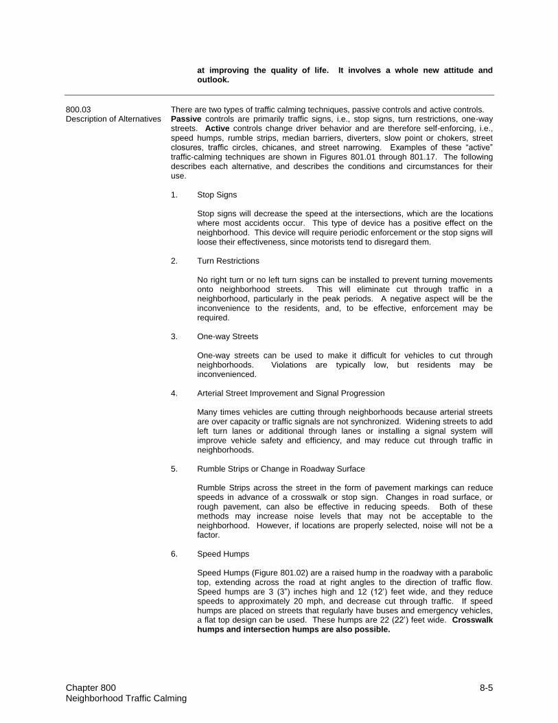
Chapter 800 8-5 Neighborhood Traffic Calming
at improving the quality of life. It involves a whole new attitude and outlook.
800.03 There are two types of traffic calming techniques, passive controls and active controls. Description of Alternatives Passive controls are primarily traffic signs, i.e., stop signs, turn restrictions, one-way
streets. Active controls change driver behavior and are therefore self-enforcing, i.e.,
speed humps, rumble strips, median barriers, diverters, slow point or chokers, street closures, traffic circles, chicanes, and street narrowing. Examples of these “active” traffic-calming techniques are shown in Figures 801.01 through 801.17. The following describes each alternative, and describes the conditions and circumstances for their use.
1. Stop Signs Stop signs will decrease the speed at the intersections, which are the locations
where most accidents occur. This type of device has a positive effect on the neighborhood. This device will require periodic enforcement or the stop signs will loose their effectiveness, since motorists tend to disregard them.
2. Turn Restrictions No right turn or no left turn signs can be installed to prevent turning movements
onto neighborhood streets. This will eliminate cut through traffic in a neighborhood, particularly in the peak periods. A negative aspect will be the inconvenience to the residents, and, to be effective, enforcement may be required.
3. One-way Streets One-way streets can be used to make it difficult for vehicles to cut through
neighborhoods. Violations are typically low, but residents may be inconvenienced.
4. Arterial Street Improvement and Signal Progression Many times vehicles are cutting through neighborhoods because arterial streets
are over capacity or traffic signals are not synchronized. Widening streets to add left turn lanes or additional through lanes or installing a signal system will improve vehicle safety and efficiency, and may reduce cut through traffic in neighborhoods.
5. Rumble Strips or Change in Roadway Surface Rumble Strips across the street in the form of pavement markings can reduce
speeds in advance of a crosswalk or stop sign. Changes in road surface, or rough pavement, can also be effective in reducing speeds. Both of these methods may increase noise levels that may not be acceptable to the neighborhood. However, if locations are properly selected, noise will not be a factor.
6. Speed Humps Speed Humps (Figure 801.02) are a raised hump in the roadway with a parabolic
top, extending across the road at right angles to the direction of traffic flow. Speed humps are 3 (3”) inches high and 12 (12’) feet wide, and they reduce speeds to approximately 20 mph, and decrease cut through traffic. If speed humps are placed on streets that regularly have buses and emergency vehicles, a flat top design can be used. These humps are 22 (22’) feet wide. Crosswalk humps and intersection humps are also possible.

Chapter 800 8-6 Neighborhood Traffic Calming
7. Pedestrian Refuge Island Pedestrian refuge islands (Figures 801.03 and 801.04) in the middle of the street
provides a safe haven for pedestrians to cross the street. If placed at an intersection, the island will function as a diverter to restrict through traffic. This device will reduce vehicle speeds. May require some parking removal and may inconvenience some residents. The median can be aesthetically pleasing.
8. Street Narrowing or Curb Extension Street narrowing or curb extensions (Figure 801.05) at a critical intersection will
reduce the crossing distance for pedestrians and makes pedestrian crossing point more visible to the motorist. This device will also reduce speeds since the motorist visual sight line is obstructed. Provides space for landscaping. Prevents vehicles from passing other vehicles that are turning. May require some parking removal.
9. Traffic Circles Traffic Circles (Figure 801.06) are raised landscaped islands placed in an
intersection, and their primary purpose is to reduce vehicle speeds and accidents, and they discourage cut through traffic in neighborhoods. May require some parking removal, and be restrictive to large vehicles if not properly designed.
10. Diverters Diverters (Figures 801.07, 801.08, and 801.09) can be either diagonal or partial.
A diagonal diverter is a barrier placed diagonal across an intersection. Its primary purpose is to reduce speed and cut through traffic. Landscaping is necessary to create new sight lines. A partial diverter is a barrier island at an intersection in which one direction of the street is blocked. May be an inconvenience to residents.
11. Street Closures Street closures (Figure 801.10) are full closures of streets to eliminate cut
through traffic. A cul-de-sac is required to provide a turn-a-round. May inconvenience some residents and may reduce accessibility for emergency vehicles.
12. Curb Radius Reduction Curb radius reduction (Figure 801.11) at intersection is intended to slow turning
vehicles and reduce pedestrian crossing path. The radius should accommodate a passenger vehicle. Usually a 10 to 20 foot radius will be required. Primary application is for local streets.
13. Chicanes Chicanes (Figures 801.12 and 801.13) are a form of curb extension built at a 45-
degree angle that alternate from one side of the street to the other. They will effectively reduce speed and decrease traffic volumes in the neighborhood.
14. Summary Each traffic calming alternative has appropriate applications and uses. Each
addresses the various objectives of traffic calming more or less effectively than others. Although the application of each device varies by conditions the following is a general list of traffic calming devices by objective.

Chapter 800 8-7 Neighborhood Traffic Calming
Traffic Calming Devices by Objective
Reduce speed Reduce Cut-Through Traffic
Improve Safety Improve Aesthetics
Traffic Circles Diverters Radius Reduction Curb Extensions
Curb Extensions Street Closures Raised Sidewalks Median Barrier
Median Barrier Turn Restrictions Median Barriers Chicanes
Radius Reduction One-Way Streets Enforcement Traffic Circles
Speed Humps Partial Closures Radius Reduction
Diverters Speed humps Diverters
Chicanes Median Barriers Street Closure
Rumble Strips Traffic Circles
FIGURE 1 BENEFITS/DISBENEFITS FOR TRAFFIC CALMING ALTERNATIVES
Traffic Calming Devices (Active Controls):
BENEFITS DISBENEFITS
Calming Alternative
Volume Reduction
Speed Reduction
Noise & Pollution
Safety Access Restriction
Emergency Vehicle
Maintenance Problems
Levels of Violation
Traffic Circle
Possible Minor No Change
No Docum. Problems
None Some Constraint
Vandalism Low
Curb Extension
Unlikely Minor No Change
Improved for Pedestrians
None No Problems
None N/A
Median Barrier
Yes On Curves
Decrease Improved Right Turn Only
Minor Constraint
None Low
Street Closure
Yes Likely Decrease Shifts Accidents
Total Some Constraint
Vandalism Low
Diverters Yes Likely Decrease Shifts Accidents
Left/Right Turn Only
Some Constraint
Vandalism Low
Speed Humps
Possible Likely No Change
No Docum. Problems
None Some Constraint
Street Cleaning
N/A
Rumble Strips
Possible Possible Increase Possible Improvement
None No Problems
Street Cleaning
N/A
Radius Reduction
Possible Likely No Change
Improved None Minor Constraint
None Low
Chicanes Possible` Likely No Change
Improved None Minor Constraint
None Low

Chapter 800 8-8 Neighborhood Traffic Calming
Traffic Control Devices (Passive Controls):
BENEFITS DISBENEFITS
Calming Alternative
Volume Reduction
Speed Reduction
Noise & Pollution
Safety Access Restriction
Emergency Vehicle
Maintenance Problems
Level of Violation
Stop Signs Possible Minor No Change
Improved None No Problems
Vandalism Moderate
Improved Arterial Capacity
Possible Minor No Change
Unclear None No Problems
None N/A
One-Way Streets
Yes None Decrease Unclear Restricted One Direction
Restricted One Direction
No Problems
Low
Turn Restrictions
Yes Likely Decrease Improved No Turn(s)
No Problems
No Problems
Moderate
800.04 1. Purpose Speed Hump – Design and Construction The purpose of this recommended practice is to provide guidelines for the design Guidelines of speed humps. They consist of raised pavement constructed or placed in, on,
and across or partly across a roadway. For the purpose of this recommended practice, speed humps are defined as a roadway geometric design feature whose primary purpose is to reduce the speed of vehicles traveling along the roadway, and decrease the number of cut through traffic.
2. Design A. Dimensions and Cross Sections – The parabolic speed hump as
shown in Figure 801.01 should be used. The 3 (3”) inch hump can be expected to cause speeds of from 20 to 25 mph at the hump, with a 4 (4”) inch hump creating crossing speeds of 15 to 20 mph. Humps should not exceed 4 (4”) inch in height, and a 3 (3”) inch height is generally considered more acceptable. The flat top design 22 (22’) feet has the same approach dimensions of 6 (6’) feet with 10 (10’) feet in the middle. These humps are used on streets that may have buses and emergency vehicles.
B. Spacing and Location – Current practice indicates that speed humps
within a series are normally placed from 200 (200’) feet to 750 (750’) feet apart (Figure 801.02).
C. Traffic Signs – The warning sign used for speed humps is the
standard MUTCD (Manual on Uniform Traffic Control Devices) W8-1 “Bump” warning sign (Figure 801.02). The sign is installed in advance of the hump and at the hump. Advance warning signs should be located based on MUTCD and should be located based on MUTCD Table II-1, “A Guide for Advance Warning Sign Placement Distance”. Advisory speed plates are also required.
In certain instances it may be justified to install special attention flags or flashing lights to speed hump warning signs. These devices are sometimes used in the initial installation period or in locations where unusual combinations or roadway or vehicle operating conditions present special conditions that warrant additional warning devices.
D. Markings – Special markings on the hump should be installed in
conformance with MUTCD guidelines, and as shown in Figure 801.02. E. Installation Angle – Speed humps should be installed at a right angle to
the centerline tangent of the roadway.

Chapter 800 8-9 Neighborhood Traffic Calming
F. Drainage and Utilities – Speed humps should be installed with appropriate
provisions made for roadway drainage and utility access, or at the crest of a vertical curve. Humps should generally not be located over or contain maintenance access holes, or be located adjacent to fire hydrants.
Ideally, a hump should be installed at a location immediately on the
downside of an existing drain inlet. If this is not feasible, the construction of a bypass drain or other treatment to route water around the hump should be considered.
G. Coordination with Street Geometry – A thorough on-site analysis of
roadway geometrics should be performed to ensure that speed humps would not be introduced at a crucial point in the roadway system, e.g., a severe combination of horizontal, vertical curvature and/or street gradient. Speed humps should normally be considered only for use on streets with grades of 8 percent or less approaching the hump.
H. Coordination with Traffic Operations – Speed humps should not be
installed within 250 (250’) feet of a traffic signal or within an intersection or driveway. This suggestion is not intended to apply to use of a raised intersection as a valid traffic management technique.
I. Location Elements – If possible, speed humps should be installed at a
street light to improve night time visibility. Likewise, if possible, speed humps should be installed near property lines for aesthetic reasons.
3. Construction
The construction of the speed hump can be asphalt, pre-cast concrete sections,
concrete, or brick/concrete pavers. Experience has shown that the use of soft material will result in deformation as the top of the hump is pushed in the direction of the traffic stream. This will vary per location depending on the daily traffic volume and vehicle types.

Chapter 800 8-10 Neighborhood Traffic Calming
SECTION 801 NEIGHBORHOOD TRAFFIC CALMING STANDARD FIGURES
801.01 Speed Humps 801.02 Pedestrian Refuge Island 801.03 Pedestrian Refuge Island 801.04 Curb Extension 801.05 Traffic Circle 801.06 Diagonal Diverter 801.07 Partial Diverter (Exit Only) 801.08 Partial Diverter (Entrance Only) 801.09 Street Closure (Cul-De-Sac) 801.10 Curb Radius Reduction 801.11 Chicane 801.12 On-Street Parking (Chicane)
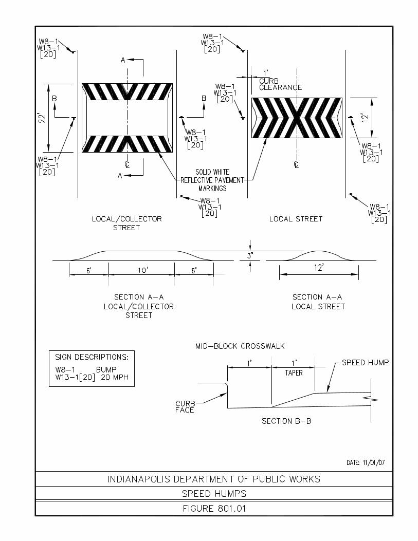


Chapter 900 9-1 Cultural Trail
CHAPTER 900 INDIANAPOLIS CULTURAL TRAIL
Chapter 900 9-2 Cultural Trail
CHAPTER 900 Indianapolis Cultural Trail
900.01 This chapter provides information for the design and construction of the Cultural Introduction Trail. The Cultural Trail is a unique, urban bike and pedestrian path that will connect all
six Indianapolis cultural districts to downtown Indianapolis. There also is information to assist with surface restoration of the Cultural Trail due to
maintenance or construction activities.
900.02 Any linear construction project has many varying design considerations and is difficult General Design to generate standards that will cover all situations. This section will give information to
assist the designer with the development of construction documents. General design of the Cultural Trail shall meet all local, federal and ADA (American
Disability Act) regulations.
900.03 Combined pedestrian/bike path width shall be a minimum of twelve feet (12’). Trail Widths Pedestrian path width shall be a minimum of nine feet (9’). Bike path width shall be a minimum of eight feet (8’).
900.04 Curb ramp design shall meet all design criteria as dictated in Chapter 400. For Curb Ramps additional information, see ADA regulations.
900.05 All portland cement concrete pavement, concrete sidewalk, concrete sidewalk under General Materials pavers, compacted aggregate base #53 and compacted subgrade shall be in
accordance with INDOT Standard Specifications.
900.06 General Unit Pavers a. Precast concrete unit pavers shall be in accordance with the following: 1.) Concrete Unit Pavers shall be tested in accordance with ASTM 170-
90 to have a minimum compressive strength of 8.500 psi. 2.) Concrete Unit Pavers shall meet or exceed the following test results: i. Absorption: less than 3% in accordance with ASTM C97-90 ii. Density: 150 lbs/cu ft. iii. Flexural: 1,100 psi 3.) Concrete Unit Pavers shall have spacers on all four sides providing a
uniform 1/16 inch joint, unless noted otherwise. 4.) Concrete Unit Pavers shall have beveled edges, unless noted
otherwise. 5.) Pavers shall be fabricated of Coplay Cement, Type I, Buff.
Aggregates should be a blend from 200 mesh to 5/8” with a light gray color. The aggregate used should have a PA S.R.L. Test of H and a specific gravity of 2.79 and absorption of 2.60. The aggregates should be washed with no deleterious substances, with no thin or elongated pieces. The aggregates should have an L.A. abrasion test of 21 and L.A. rattles loss test of 21.8% (at 500 revolutions). The aggregates should have a wash test of less than 1%, including materials lost by washing the aggregate and those finer than 200 mesh.
6.) Concrete Mix should be prepared in a stationary mixer to a 5” slump, mixed a maximum time of 2 minutes and placed in the mold in a homogenous state. The whole of the paver is to be of the same

Chapter 900 9-3 Cultural Trail
design and a single mix system. Hydraulic pressure to be employed should be a minimum of 800,000 pounds without use of any vibration.
7.) Concrete pavers are to be integrally colored with custom blended shades.
b. Asphalt Unit Pavers shall be in accordance with the following: 1.) Asphalt Pavers shall contain clean, hard, unweathered stone, which
shall be crushed in such a manner that the particles shall be as nearly cubic as possible and vary in size up to 3/8”. The inorganic dust or filler contained in the block shall be produced from sound limestone or other approved material.
2.) The asphalt cement in each paver shall conform to Type 3 asphalt ASTM Designation D-312 with a penetration at 77 Degrees F, 100 G, 5 sec. of minimum 15 mm and maximum of 35 mm. The pavers shall have a permissible plus or minus tolerance of 1/8” in any direction. The average absorption of a set of four pavers shall not be more than 0.25%.
3.) Asphalt Pavers shall meet or exceed the following test results: i. Absorption: 0.85% ii. Brittleness at Low Temperature: No breakage at 532 in. lb. of
impact force after immersion in water for 48 hours and frozen at -40 deg. F for 48 hrs. Tested in frozen state.
iii. Indentation Resistance: resistance to indentation under a 1000 psi load after exposure to the following conditions:
Condition: Avg. Indentation at 1000 PSI (in.) 74 deg. F, 48 hours 0.036” 150 deg. F, 48 hours 0.073” Calcium Chloride, 3 month immersion 0.052” Motor Oil, 3 month immersion 0.101” 2. Manufacturer a. Subject to compliance with requirements, products from one of the following
shall be provided: 1.) Hanover Architectural Products, Hanover PA, (717) 637-0500 2.) Or approved equal. 3. Unit Paver Type, Size, Thickness, and Color: For location of each paver type, see
Culture Trail Standard Figures 901.04, 901.05 and 901.06 a. Unit Paver Type A: 1.) Asphalt Block, Tudor Finish, by Hanover or approved equal. 2.) 8” hexagonal block x 2” thickness 3.) See plans for locations, color designations, and laying patterns. 4.) Color 1: Hanover designation of Matrix #A80011. 5.) Color 2: Hanover designation of Matrix #A80013. b. Unit Paver Type B: 1.) Asphalt Block, Tudor Finish, by Hanover or approved equal. 2.) 8” hexagonal block x 3” thickness 3.) See plans for locations, color designations, and laying patterns. 4.) Color 1: Hanover designation of Matrix #A80011. 5.) Color 2: Hanover designation of Matrix #A80013. c. Unit Paver Type C. 1.) Precast Concrete Paver, “Slatefaced Prest Paver” by Hanover, or
approved equal. 2.) 12” x 24” x 2” thickness, set in pattern as indicated on plans. 3.) Pavers shall not have spacer ribs on sides and shall not have beveled
edges. 4.) Pavers shall be laid with a 1/16” minimum and 1/8” maximum joint.

Chapter 900 9-4 Cultural Trail
5.) See plans for locations, color designations, and laying patterns 6.) Color: Hanover designation of Bluestone #M2374. d. Unit Paver Type D: 1.) Precast Concrete Paver, “Slatefaced Prest Paver” by Hanover, or
approved equal. 2.) 12” x 12” x 3” thickness, set in pattern as indicated on plans. 3.) Pavers shall not have spacer ribs on sides and shall not have beveled
edges. 4.) Pavers shall be laid with a 1/16” minimum and 1/8” maximum joint. 5.) See plans for locations, color designations, and laying patterns 6.) Color: Hanover designation of Bluestone #M2374. e. Unit Paver Type E. 1.) Precast Concrete Paver, “Prest Brick”, Tudor Finish, by Hanover, or
approved equal. 2.) 4” x 8”, gauged to 2-1/4” thickness. 3.) See plans for locations, color designations, and laying patterns. 4.) Color 1: Hanover designation of “Brown” or approved equal 5.) Color 2: Hanover designation of “Tan” or approved equal. 6.) Color 3: Hanover designation of “Charcoal” or approved equal. f. Unit Paver Type F: 1.) Precast Concrete Paver, “Detectable Warning Paver”, Tudor Finish,
by Hanover, or approved equal. 2.) 12” x 12”, gauged to 2-1/4” thickness 3.) See plans for locations, color designations, and laying patterns. 4.) Color: Hanover designation of “Glacial White” or approved equal. 5.) Pavers shall be manufactured in accordance with the Americans with
Disabilities Act (ADA) and meet ADA aligned dome requirements. 4. Setting Materials a. HMA Setting Materials shall be in accordance with Section 402. b. HMA Setting mix shall be comprised of 7% asphalt and 93% sand. c. Sand for mix shall be of the following gradation: SIEVE SIZE PERCENT PASSING 3/8 INCH 100% #4 95 to 100% #8 80 to 100% #16 50 to 80% #30 25 to 60% #50 7 to 30% #100 1 to 10% #200 0 to 3% 5. Primer for Base: a. Prime coat shall be in accordance with Section 405. 6. Neoprene Modified Asphalt Adhesive:
a. Neoprene Modified Asphalt Adhesive shall contain 75% ( 1%) of solids (base) in a mineral spirit solvent.
b. Density shall be 8.0 to 8.5 pounds per gallon. c. The base shall comprise 2% neoprene, 10% asbestos-free fibers and 88%
asphalt. d. Delivery and storage shall be in accordance with the manufacturer’s
instructions, maintaining a temperature range of 45 to 95 F.
e. The adhesive shall be applied when temperatures are above 70 F; at a coverage rate of 40 square feet per gallon by brush, squeegee or trowel.
f. The adhesive shall be spread at least two hours before setting the pavers.

Chapter 900 9-5 Cultural Trail
7. Concrete for Base Slab: Concrete base shall be in accordance with INDOT Standard Specifications Section 604, 610, and as indicated on plans.
8. Sand for Joints: Fine, sharp, washed, natural sand shall comply with gradation
requirements of ASTM C144 and INDOT Standard Specifications Section 940. 9. Joint Sand Stabilizer: a. The joint sand stabilizer shall be an epoxy resin or polyurethane resin
product, capable of penetrating the joint sand prior to polymerization. It shall seal the top surface of the paver joints without causing discoloration, noticeable sheen or the coefficient of friction to fall below the specified value for the surface of the pavers.
b. Acceptable Products/Manufacturers: The joint sand stabilizing material shall be one of the following, or approved equal.
1.) Surebond SB-1300 as manufactured by Surebond, Inc., 500 E. Remington Road, Schaumburg, IL 60173 (phone: 847-843-1818)
2.) Joint sand material as manufactured by Angelus Block Company, inc., 11374 Tuxford Street, Sun Valley, CA 91352-2678 (phone: 818-767-8576)
3.) Joint sand material as manufactured by Morton International, 100 North Riverside Plaza, Chicago, IL 60606 (phone: 800-257-9596)
c. Delivery and storage shall be in accordance with the manufacturer’s
instructions, maintaining a temperature range of 45 to 95 F. 10. Paver Restraint Edging: a. “AsphaltEdge” as manufactured by PermaLoc Corporation, Holland MI
49424, telephone (800) 356-9660, or approved equal. 1.) Size: 0.210 inch thick exposed top lip x 2” high x 8 feet long sections 2.) Material/Shape: extruded aluminum, alloy 6005, T-5 hardness.
Horizontal base to have upward facing angle profile designed to integrate restraint and asphalt surfaces for straight-line and curvilinear applications. Section shall have holes in base spaced 4 inches apart along its length to receive anchors.
b. Connection Method: Section ends shall splice together with horizontal 0.060 inch thick x 1 inch wide x 4 inches long aluminum sliding connector.
c. Anchors: 3/16 inch x 1-1/2 inches or longer Ardox concrete nail, or drive pin fastener equal to Hilti DX 40 powder actuated pin or Ramset Trakfast Automatic Fastening System pin.
d. Finish: Natural Mill Aluminum.
900.07 Due to construction activities and maintenance of the Cultural Trail, surface restoration Surface Restoration will be required. It is the contractor’s responsibility to restore the trail’s sub-surface and
surface to original or better condition. Pavers shall be removed and stock piled during construction and replace after the construction is finished. Any pavers that are damaged during the construction process will need to be replaced with the same material. See Section 901.06 for paver information.
900.08 When construction requires installation sub-surface features, the backfilling and trench Trench Construction restoration shall be in accordance with Chapter 200 of this manual. All restoration
material depths shall match existing.
900.09 Before any construction activities commence, all permits shall be obtained. All Permitting permitting requirements are as directed by Chapter 200 of this manual.
900.10 All construction activities, inspection and testing shall be in accordance with Chapter Construction 200 of this manual

Chapter 900 9-6 Cultural Trail
SECTION 901 Curb Ramp Standards Figures
901.01 Separated Pedestrian/Bicycle Trail Section
901.02 Combined Pedestrian/Bicycle Trail Section
901.03.1 Typical Intersection Separated Pedestrian/Bicycle Trail Paver Layout
901.03.2 Typical Intersection Combined Pedestrian/Bicycle Trail Paver Layout
901.03.3 Typical Drive Approach Unit Paver Layout
901.03.4 Key Notes
901.04 Trench Restoration Detail

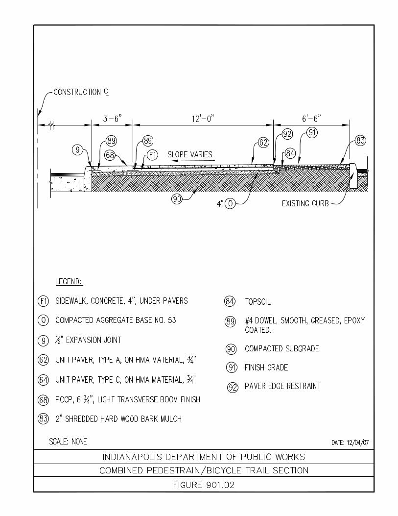


Chapter 1000 10-1 Transit Standards
CHAPTER 1000 Transit Standards
Chapter 1000 10-2 Transit Standards
CHAPTER 1000 Transit Standards
1000.01 As a municipal corporation of Marion County, IndyGo is governed by an independent Introduction board made up of appointees by the Mayor of Indianapolis and the City County Council.
The board approves IndyGo policies relating to operations, contracted services, safety, finance and overall corporation structure.
IndyGo invests in transit amenities and currently maintains shelters, benches, bike racks
and solar lights at stops.
1000.02 Any linear construction project has many varying design considerations and is difficult General Design to generate standards that will cover all situations. This section will give information to
assist the designer with the development of construction documents. General design of transit amenities shall meet all local, federal and ADA (American
Disability Act) regulations. The criteria for design shall conform with the most current version of the IndyGo Specifications for the placement and design of bus stops and bus tournouts, and the design/layout of shelters, benches and bike racks that may be installed.