![The Carrollton sun (City of Carrollton) 1860-12-29 [p ] · Sl, . i. Evrery oltlflilg ad es', , stoir, oiuon 1 slUing cllotoks inad slies., anot. their owIn. ... r shliel shlll piay](https://static.fdocuments.in/doc/165x107/5b8835277f8b9a46538d6de5/the-carrollton-sun-city-of-carrollton-1860-12-29-p-sl-i-evrery-oltlflilg.jpg)
City of Carrollton, TX | Home
23
Transcript of City of Carrollton, TX | Home


SP-1
REVISION 1: February 26,2016
END OF SECTION
SECTION 06200FINISH CARPENTRY
SUMMARY:Installation of metal doorsInstallation of metal framesInstallation of hardware
RELATED SECTIONS:Refer to the following related Sections:
Section 08100 – Metal Doors and Frames Section 08700 – Hardware
ENVIRONMENTAL REQUIREMENTS:Install finish carpentry products only when temperature and humidity conditions have been stabilized and will be maintained. Maintain temperature and moisture conditions as recommended by woodwork fabricator from date of installation through remainder of construction period.
INSPECTION:Make detailed inspection of Work area and adjoining construction prior to beginning installation. Verify governing dimensions and other permissible dimensional tolerances. Examine supplied hardware. Verify correct size, type, quantity and anchorage for proper installation of corresponding doors, woodwork, millwork, etc, requiring hardware. Examine doors and frames (including glazing frames). Verify doors and frames are correct size, type and preparation for proper hanging and installation of corresponding units. Inspect frames for rack, twist, and out-of-square. Replace uncorrectable frames as necessary. Report in writing unsatisfactory conditions encountered; do not begin installation until conditions are correct. Beginning installation signifies acceptance of conditions.
FRAME INSTALLATION:Install frames true and plumb. Maintain alignment until permanently built into wall. Set and maintain proper door clearances. Coordinate installation with adjacent Work to ensure proper clearances and to allow for maintenance and adjustments. Install labeled frames in accordance with U.L. requirements.
FRAME TOUCH-UP:Touch-up damaged coatings and finishes as recommended by the manufacturer. Repair minor damage to frames and accessories. Unacceptable touch-up and repair areas shall be replaced to the satisfaction of the Architect.
METAL DOOR INSTALLATION:Install in accordance with manufacturer’s written instructions. Install accurately in frame, within clearances specified. Install hardware in accordance with manufacturer’s written instructions and associated templates. Do not install door in frame set out of plumb or square. Install to operate freely, but not loosely, free from hinge bound conditions, striking or binding. Do not install in frames which would hinder operation of doors. Hang free from rattling when in latched position. Coordinate installation of glass and glazing.
INSTALLATION TOLERANCES:
Maximum Diagonal Distortion: 1/8 inch measured with straight edge, corner to corner.
Maximum clearances: 1/8” at jamb and head; 3/16” at threshold or saddle; 1/2” over decorative floors without thresholds.
ADJUSTING AND REPLACEMENT:Adjust and check each door to ensure proper operating and function. Replace or rehang doors which are hinge bound and do not swing or operate freely. Replace doors which are warped, twisted, or which are not in true planes. Replace prefinished doors damaged during installation.
HARDWARE INSTALLATION: Install in accordance with manufacturer’s written instructions. Install in accordance with reviewed Hardware Schedule. Install to allow full range of adjustments.
ADJUSTING AND CLEANING:Check and adjust each operating hardware item to ensure proper operating or function of unit. Adjust closers to comply with ADA Requirements. Lubricate moving parts as recommended by hardware manufacturer. Use graphite type lubrication if none other is recommended. Repair or replace defective materials or units which cannot be adjusted and lubricated to operate freely and smoothly. Reinstall items found improperly installed.
FINAL ADJUSTMENT:Prior to Final Acceptance date, readjust and re-lubricate as necessary. Instruct Owner’s designated personnel in proper adjustments and maintenance of hardware.
CLEANING:Clean exposed surfaces using non-abrasive materials and methods recommended by manufacturer.
moisture content was reduced to maximum 19% for lumber and 15% for plywood after treatment.
QUALITY ASSURANCE:
Lumber Grading: Lumber Grading Rules and Wood Species shall be in accordance with voluntary Product Standards. Follow grading rules of appropriate associations for materials furnished. Identify lumber and plywood by official grade mark.
Lumber: Include symbol of grading agency, mill name, grade, species, grading rules and condition of seasoning at time of manufacturer.
Plywood: Include type, class identification index, and agency mark.
Preservative and Pressure Treated Lumber and Plywood: Comply with American Wood Preservers Bureau Standards.
LUMBER:
Sizes: Surfaced four sides with dressed sizes conforming to the requirements of referenced standards.
Moisture Content: Kiln dried with moisture content not to exceed 19%.
Wood Treatment: Pressure-treat wood items with water-borne preservatives. After treatment, kiln-dry to a maximum moisture content of 15%. Treat indicated items and the following: Wood sills, sill plates Wood concealed members in contact with masonry or concrete Wood framing and blocking in connection with roofing and flashing
Treated Wood: No. 2 Southern Yellow Pine
Other Framing Lumber: Standard or better Douglas Fir, or No. 2 Southern Yellow Pine
Plywood: Yellow Pine C-D, exterior glue
FASTENERS:Provide size and type indicated, and as recommended by applicable standards. Comply with applicable Federal Specifications for nails, staples, screws, bolts, nuts, washers and anchoring devices. Provide galvanized nails and fasteners for anchoring treated lumber and exterior wood.
INSTALLATION:Discard units of material with defects which might impair quality of work, and units which are too small to fabricate work with minimum joints or optimum joint arrangement.
COORDINATION:Coordinate Work with other trades and provide cutting and patching required to accommodate other Work.
FRAMING:Accurately saw-cut lumber to seat square on bearings. Fit closely into proper location, true to line and grade, plumb and level. Frame, anchor, tie and brace members to develop strength and rigidity required for purpose for which they are to be used. Do not stress members in excess of design strength. Secure members permanently in position with proper fastenings to render parts rigid.
Provide temporary enclosures, partitions, stairs and protective covers as required. Provide temporary bracing as required until Work is completed and securely anchored. Leave temporary bracing in place as long as required for safety. As Work progresses, securely connect and brace Work to compensate for dead load, wind and erection stresses.
BLOCKING AND FURRING:Coordinate with Section 09250 – Gypsum Board for the installation of wood blocking and furring in drywall framing.
Provide wood blocking, nailers, grounds, furring, etc. as required for securing Work of other trades. Shape, install and secure wood blocking items properly to receive, engage or support other Work. Secure wood blocking items to drywall framing with appropriate screw attachment. If treated items are cut after treatment, coat cut surface with heavy brush coat of same chemical used for treatment.
HARDWARE:Provide nails, screws, bolts, anchors, washers, clips, shields and other rough hardware necessary to complete Work. Bore holes for bolts true to line and of same diameter as bolts. Drive bolts into place with a tight fit; provide plates or washers where bolt heads or nuts are in contact with wood.
CLEANING:Dispose of excess materials and debris away from site.
PROTECTION:Protect Work from moisture absorption and subsequent warping or deterioration until completion.
FORMS:Set forms accurately to required grades and alignment. Adequately brace to withstand loads applied during concrete placement. Leave forms in place for minimum 12 hours after completion of finishing operation.
REINFORCEMENT:Provide reinforcement as indicated. Install reinforcing in middle third of flatwork.
Flatwork: Strike off concrete with transverse screed, shaped to provide cross-slope where required, guided by and resting on screeds or side forms. Follow screeding operation with longitudinal float. Stoppage of concrete placing shall be at planned location of either expansion or control joint.
FINISHING:Test floated surfaces with 10’-0” straight edge for conformance to required slope and specified tolerance. Correct as required to bring within tolerance. Finish surface to a gritty texture heavy burlap finish. Tool edges to provide smooth dense surface with 1/8” radius.
CURING AND PROTECTION:Immediately after finishing operations are completed, cure exposed surfaces to prevent damage due to extreme temperatures or temperature changes. Protect finished concrete from damage by elements or construction operations.
JOINT SEALANT:Seal paving joints with joint sealant with primer and backer rod as recommended by manufacturer.
END OF SECTION
SECTION 04090MASONRY FLASHING
WORK INCLUDED:Flexible, self-adhering flashing at sill, header and thru-wall locations.
ENVIRONMENTAL REQUIREMENTS:Follow manufacturer’s instructions for cold weather installation. Do not use frozen materials or build upon frozen Work.
MASONRY FLASHINGS:Manufacturers: Acceptable manufacturers include:
Polyguard Products, Inc
Masonry flashing: Polyguard 400 Thru Wall Flashing, 40 mil, self-adhering, rubberized asphalt with polyethylene top surface film. Provide pre-fabricated end dams and corners. Provide manufacturer’s recommended liquid adhesive surface preparation and mastic sealer.
INSTALLATION:Install Work in coordination with masonry or other subsequent finish to prevent prolonged exposure of flashings to harmful elements.
MASONRY FLASHINGS:Provide masonry flashings at masonry sills, above opening heads, and as indicated. Provide in widths adequate to extend flashing 8” minimum up vertical substrate. Install pre-fabricated end dams at terminations. Install pre-fabricated corners at inside and outside corner locations. Prepare substrate as recommended by the manufacturer, including liquid adhesive. Seal top terminating edges and other locations as recommended by the manufacturer.
CLEANING: Properly protect adjacent surfaces. Clean as necessary. Dispose of excess materials and debris away from site.
PROTECTION: Protect Work against damage until installation of masonry or other finish. Replace, or repair to the satisfaction of the Architect, Work that becomes damaged prior to finish installation. END OF SECTION
SECTION 06100ROUGH CARPENTRY
WORK INCLUDED:Wood framing, furring, grounds, nailers, and blockingPreservative treated materialsFasteners and related accessories
SUBMITTALS:
Product Data: Provide technical data on wood preservative and fire retardant materials, including application techniques and instructions.
Pressure Treated Wood: Submit certification by treating plant stating chemicals and process used, net amount of salts retained, and conformance with referenced standards. Submit certification for water-borne preservative that
Protect from damage by weather, excessive temperatures and construction operations.
ACCEPTABLE MANUFACTURERS:Acceptable manufacturers are listed in groups. Manufacturer’s item number indicated refers to the initial manufacturer listed in each group unless noted otherwise. Item numbers are listed to establish desired features and quality. Other manufacturers listed are presumed to offer similar products with equivalent features and quality. Substitutions of other manufacturers will be considered prior to Bid, provided adequate information is submitted in a timely fashion to allow Architect’s review of proposed substitution.
Proposed equivalent products must additionally match specified color and finish selections to the satisfaction of the Architect to be considered as equivalent. Custom color and/or finish may be required for proposed equivalent products to be acceptable to the Project color and finish scheme.
INSPECTION:Make detailed inspection of Work area and adjoining construction prior to beginning installation. Verify governing dimensions and other permissible dimensional tolerances. Report in writing unsatisfactory conditions encountered; do not begin installation until conditions are correct. Beginning installation signifies acceptance of conditions.
INSTALLATION:Install Work in strict accordance with manufacturer’s recommendations and referenced standards.
CLEANING:
Materials and equipment:Use only cleaning materials recommended by manufacturer of surface to be cleaned. Use cleaning materials only on surfaces recommended by cleaning material manufacturer. Provide proper containers for storing and transporting waste. Provide proper equipment for specific cleaning functions.
Cleaning during construction:Execute cleaning daily to insure that building, grounds and public properties are maintained free from accumulations of waste materials and rubbish; remove such accumulations from premises daily or properly store in waste containers for periodic removal from site. Wet down dry materials and rubbish to lay dust and prevent blowing dust. Vacuum clean interior building areas when ready to receive finish painting, and continue vacuum cleaning on an as-needed basis until building is ready for Final Acceptance. Schedule cleaning operation so that dust and other contaminants resulting from cleaning process will not damage Work.
Final cleaning:Perform final cleaning just prior to, and as a condition of, Final Acceptance. Employ experienced workmen, or professional cleaner, for final cleaning. Remove waste materials, rubbish, tools, equipment, machinery and surplus materials and clean sight-exposed surfaces; leave project clean and ready for occupancy. Remove grease, dust, dirt, stains, labels, fingerprints and other foreign materials from sight-exposed interior and exterior finishes; polish surfaces so designated to shine finish. Broom clean paved surfaces; rake clean other surfaces of grounds. Clean and polish both sides of glass. Vacuum clean interior building areas.
Final cleaning of ventilation system: Replace air conditioning filters if units were operated during construction. Clean ducts, blowers and coils if air conditioning units were operated without filters during construction. Maintain cleaning until Final Acceptance.
Disposal:Properly dispose of excess materials and debris away from site.
PROTECTION:Protect Work against damage until Final Acceptance. Replace, or repair to the satisfaction of the Architect, Work that becomes damaged prior to Final Acceptance.
END OF SECTION
SECTION 02600PAVING
WORK INCLUDED:Concrete walks
Provide additional reinforcement and increased reinforcement as may be indicated herein.
Walks: 2500 psi concrete
JOB CONDITIONS:Do not begin Work of this Section prior to satisfactory test results of required subgrade testing. Do not install Work on subgrade that is not free of frost and excessive moisture.
PROJECT MANUAL INDEX
GENERAL REQUIREMENTSSection 01000 – General Requirements
TECHNICAL SPECIFICATIONS
ARCHITECTURALSection 02600 – PavingSection 04090 – Masonry FlashingSection 06100 – Rough CarpentrySection 06200 – Finish CarpentrySection 06300 – MillworkSection 07200 – Thermal ProtectionSection 07230 – Rigid Foam Board InsulationSection 07270 – Building WrapSection 07900 – Joint SealersSection 08100 – Metal Doors and FramesSection 08400 – Entrances & StorefrontsSection 08700 – HardwareSection 08800 – Glass and GlazingSection 09250 – Gypsum BoardSection 09300 – Ceramic TileSection 09500 – Suspended Acoustical CeilingSection 09650 – Resilient FlooringSection 09680 – CarpetSection 09770 – Plastic Wall PanelsSection 09900 – PaintingSection 10160 – Toilet PartitionsSection 10520 – Fire Extinguishing EquipmentSection 10800 – Toilet Accessories
SECTION 01001GENERAL REQUIREMENTS
SPECIFICATION LANGUAGE:The specification language is directed to the Contractor who is obligated by contract to the Owner. The various specification sections are created and arranged for the convenience and clarity of organization of materials, items and construction. The Contractor is responsible for the complete project requirements and any determination of division of the work among various subcontractors.
“Provide” is defined to mean the furnishing, preparing and installing complete with necessary appurtenances and accessories, fully functional for the intended purpose.
QUALITY ASSURANCE:Conform to requirements of governing authority having jurisdiction for the Work of this Project. Provide like products from a single manufacturer to ensure uniformity in quality of appearance and construction. SUBMITTALS:
Submittals, Shop Drawings, Product Data: Submit as required by Contract Documents and as appropriate to Work anticipated, clearly showing, at large scale, elevations, details, materials, shapes, sizes and methods of construction proposed, including required clearances, reinforcements, anchors, and accessories and relationship with adjacent materials. Submit product data, as applicable, including manufacturer’s installation instructions. Submit complete color charts or color samples if color selection is required.
Present submittals in a clear and thorough manner which illustrate the portion of the Work showing fabrication, layout, setting, or erection details. Drawings must be prepared by a qualified detailer and shall not be copies of the Architect’s or Engineer’s Construction Drawings. Indicate coordination with other Work. Identify field dimensions; show relation to adjacent or critical features of Work or products.
Title each submittal with Project name and number; identify each element by reference to sheets the Project Drawings number and detail, schedule, specification section or room number in the Contract Documents. Review each submittal thoroughly prior to forwarding to the Architect. Affix Contractor’s submittal review stamp with signature, date, results of review and submittal identification number (per CSI Format). Include a transmittal with each submittal group identifying submittals.
Provide submittals in electronic format. If hard copies are submitted, provide 2 copies of each submittal. The Architect will obtain electronic scans of the copies for his review. The cost of scanning will be invoice to the Contractor. Samples: Submit or mock-up as necessary for Architect’s selection and review. Provide adequate number of samples for the Architect to retain 2 copies for his records.
Fabricate Work in conformance with reviewed submittals.
MATERIALS HANDLING:Deliver materials and products in manufacturer’s labeled protective packages. Store and handle in strict compliance with manufacturer’s instructions and recommendations.
SP-2
REVISION 1: February 26,2016
Protect surrounding elements from damage or disfiguration.
MIXING:Follow manufacturer’s written instructions. Do not begin mixing until surfaces to receive sealant have been properly cleaned and prepared for application. Mix two component sealants by mechanical mixer, according to quantity required, and in proportions given by manufacturer. Mix components as slowly as possible (100 to 300 rpm) to prevent air from becoming entrained or overheating occurring during mixing.Continue mixing until color is completely uniform, without streaks or marbleized effects. Continue mixing for not less than 5 minutes when curing agent is of similar color to base material.
SEALANT INSTALLATION:Measure joint dimensions and size materials to achieve required width/depth ratios. Install joint backing as necessary to achieve a neck dimension no greater than 1/3 the joint width. Install bond breaker where joint backing is not used. Apply sealant within recommended application temperature ranges. Install sealants continuous and free of air pockets, foreign embedded matter, ridges, and sags. Tool joints concave. Sealant shall achieve a firm skin before surface coating is applied. At precompressed seals, remove shrink-wrap cover and insert into joint prior to expansion. Join strips by means of scarified joints. Use artificial heat to prompt adhesion to joint dies if required.
SEALANT SCHEDULE:
Exterior sealant: Apply sealant at joints not identified in related work and as follows:
-Exterior perimeters of hollow metal door frames and windows
-Exterior locations as indicated to close joints at dissimilar materials; and not indicated in related work.
Interior caulk: Caulk interior framing joints in exterior insulated walls including stud framing to floor slab or substrate; stud framing to columns, beams, etc.; butt joints at multiple stud framing; and other framing joints where insulation is non-continuous across the joint.
Sanitary Sealant: Apply sanitary sealant at joints between toilet accessories and adjacent wall finish. Sealant is not required at mirrors or signage.
DAMAGE REPAIR:Repair damaged sealant areas and adjacent finishes as recommended by the manufacturer. Unacceptable repair areas shall be replaced to the satisfaction of the Architect.
CLEANING:Clean adjacent soiled surfaces. Clean exposed surfaces using non-abrasive materials and methods recommended by manufacturer.
PROTECTION:Protect sealants until cured.
END OF SECTION
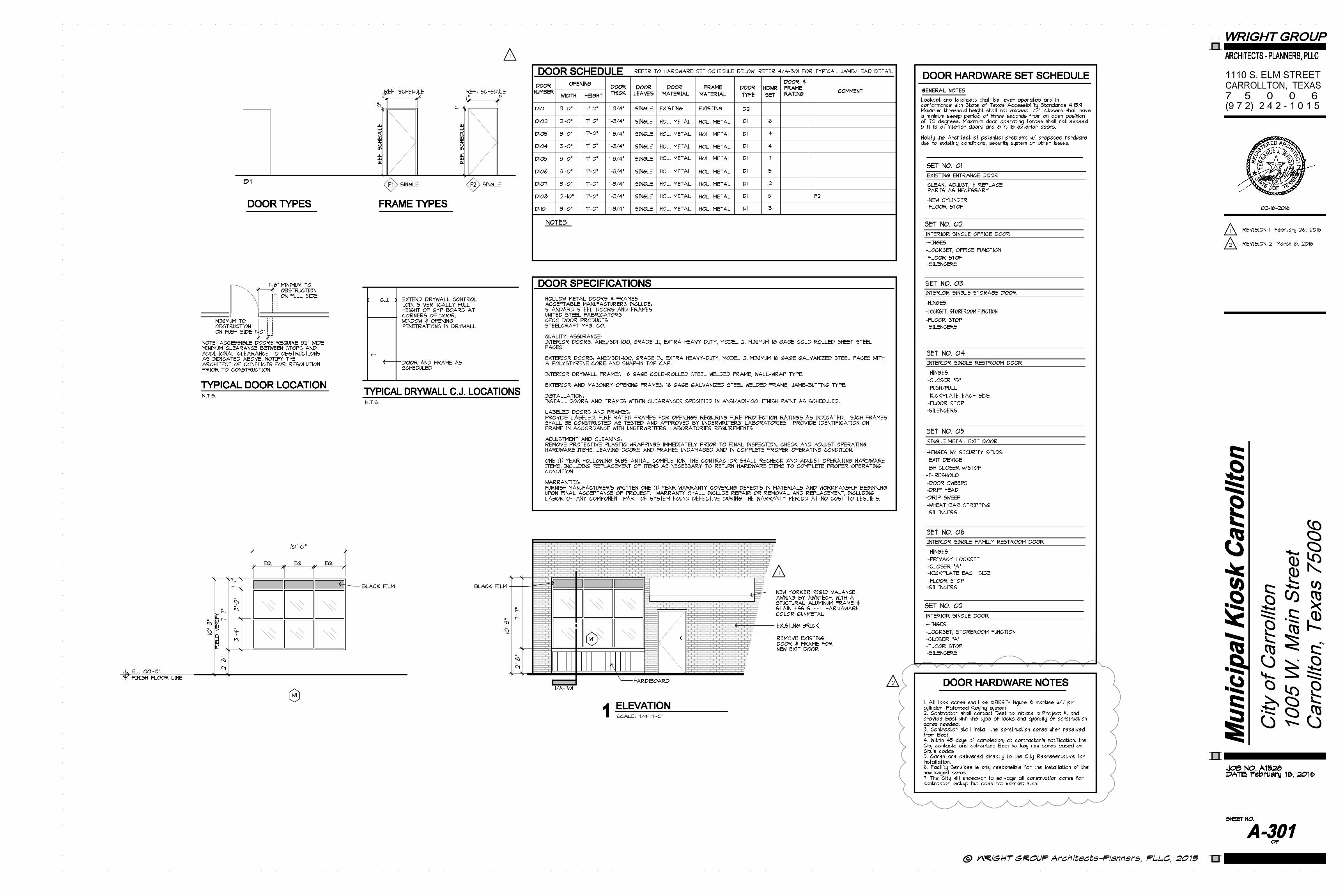
SECTION 08100METAL DOORS AND FRAMES
SUMMARY:Steel doorsFormed steel frames for doors, welded construction (no K.D. frames)
QUALITY ASSURANCE:Conform to NAAMM Standard CHM-1-74 and HMMA 861 Guide Specification for Commercial Hollow Metal Doors and Frames
HOLLOW METAL DOORS AND FRAMES:
Manufacturers: Acceptable manufacturers include:Republic Builders ProductsCeco Door ProductsSteelcraft Doors
DOORS:Fabricate of commercial quality, level, cold rolled steel conforming to ASTM Designation A-366 and free of scale, pitting or other surface defects. Provide face sheets for interior doors not less than 18 gage. Provide face sheets for exterior doors not less than 16 gage and with zinc coating of not less than 0.10 ounces per square foot.
Fabricate doors of the types and sizes shown, fully welded seamless construction with no visible seams or joints on faces or vertical edges. Door thickness shall be 1-3/4”.Provide strong, rigid and neat in appearance, free from warpage or buckle. Corner bends shall be true and straight and of minimum radius for the gage of metal used.
Stiffen face sheets by continuous vertical formed steel sections spanning the full thickness of the interior space between door faces. Provide stiffeners not less than 22 gage, spaced not
Other Openings and Penetrations:Provide flashings for other openings as required to provide weathertight barrier. Install lapped components to direct water to exterior of building.
END OF SECTION
SECTION 07900JOINT SEALERS
WORK INCLUDED:Exterior sealantInterior caulking and sanitary sealantAcoustical sealant
REFERENCES:SWI (Sealing and Waterproofers Institute) - Sealant and Caulking Guide Specification.
JOINT SEALERS AND ACCESSORIES:Manufacturers: Acceptable manufacturers include:
Pecora CorpTremco Manufacturing CoSonneborn Building Products, Division of ChemRex,
IncGeneral Electric Silicone Products DivisionDow Corning Corp
MATERIALS:
Exterior sealant: Two-part, non-sag, elastomeric sealant, Dynatrol II, General Purpose Polyurethane Sealant. Provide colors as selected by the Architect from manufacturer’s full range.
Interior caulk: One-part, non-sag acrylic latex, no: AC20, Pecora Corp. Provide no: AC20 FTR as necessary for rated assemblies. Provide colors as selected by the Architect from manufacturer’s full range.
Sanitary sealant: One-part conforming to FS TT-S-001543A, Color: match plumbing fixture or adjacent finish material; no: 898, Pecora Corp.
Acoustical caulk: One-part, non-sag acrylic latex, no: AIS-919, Pecora Corp. Provide no: AC20 FTR as necessary for rated assemblies. Manufacturer’s standard color.
ACCESSORIES:
Primer: Non-staining type, recommended by sealant manufacturer to suit application.
Joint Cleaner: Non-corrosive and non-staining type, recommended by sealant manufacturer; compatible with joint forming materials.
Joint Backing: As recommended by sealant manufacturer to suit application.
Bond Breaker: Pressure sensitive tape recommended by sealant manufacturer to suit application.
RELATED WORK:
Furnishing of sealer material and installation of joint sealers associated with the following Sections is included in the work of the indicated Section.
Refer to Section 06300 – Millwork for providing materials and installation of joint sealer between countertop and splash.
Refer to Section 08400 – Entrances and Storefronts for providing materials and installation of sealant associated with entrances, curtain walls and storefronts, including exterior and interior perimeters of aluminum curtain wall and storefront; entrance framing; and setting bed for thresholds.
Refer to Section 09250 – Gypsum Board for providing materials and installation of acoustical caulking.
Refer to Section 09650 – Resilient Flooring for providing materials and installation of caulking at resilient flooring to door frames.
Refer to Section 09900 – Painting for providing materials and installation of interior caulking associated with painted finishes at dissimilar materials.
Refer to Plumbing Work for providing materials and installation of sanitary sealant at joints between plumbing fixtures and adjacent finish materials.
PREPARATION:Clean and prime joints in accordance with manufacturer’s instructions. Remove loose materials and foreign matter which might impair adhesion of sealant. Verify that joint backing and release tapes are compatible with sealant. Perform preparation in accordance with ASTM C804 for solvent release sealants, C790 for latex base sealants, C919 for acoustical applications, and C962 for elastomeric sealants.
washers.
SEALANTS:Polyurethane or elastomeric sealants; acceptable products:OSI Quad Pro-Series, solvent release butyl rubber sealantDAP Dynaflex 230
FLASHINGS:
Flexible flashing:Self-adhering flexible flashing tape, DuPont FlexWrap, elasticized polyethylene laminate face, white, with butyl adhesive containing non-halogen fire retardant additive, 60 mils thick minimum, with 2 part siliconized paper release liner. Elastic Elongation: MD (length @ Full Extension/ Length @ Relaxed): >230% @ 70 F.
Straight flashing:Self-adhering straight flashing tape, DuPont StraightFlash, polyethlyene laminate face, white, with butyl adhesive containing fire retardant additive, 30 mils thick, with one piece siliconized paper release liner.
INSTALLATION:Install building wrap over exterior side of exterior wall sheathing, prior to installation of windows and doors. Install lower level barrier prior to upper layers to ensure proper shingling of layers. Overlap corners minimum of 12 inches. Overlap vertical seams minimum of 6 inches. Ensure building wrap is plumb and level with foundation; unroll extending building wrap over window and door openings. Attach at 12” to 18” centers on vertical stud line with suitable fastener.
Prepare window and door rough openings as follows:Prepare each window rough opening by cutting a modified “I” pattern in the building wrap. Horizontally cut wrap along bottom of header. Vertically cut down the center of window openings from the top of the window opening down to 2/3 of the way to the bottom of the opening. Diagonally cut wrap from the bottom of the vertical cut to the left and right corners of opening. Fold side and bottom flaps into window opening and fasten every 6 inches. Trim off excess. Prepare each rough door opening by cutting a standard “I” pattern in the building wrap. Horizontally cut wrap along bottom of door frame header and along top of sill. Vertically cut wrap down the center of door opening from the top of the door opening (header) down to the bottom of the door opening (sill). Fold side flaps inside around door openings and fasten every 6 inches. Trim off excess. Tape horizontal and vertical seams with sealing tape. Seal tears and cuts with sealing tape.
INSTALLATION OF FLASHINGS:
Project Conditions:Do not install flashings on wet or damp surfaces. Surfaces shall be free from dirt, oils, lubricants or other debris that may inhibit adhesion of the flashing tape to the substrate. After precipitation, allow a minimum of 24 hours for drying before installing the flashing tape. Install flashings at temperatures above 40 degrees F. Preparation:Clean loose dust or dirt from surface wherever flashing tape is to be applied by wiping with a clean dry cloth or brush. Remove existing weather barriers, flashings, carrier or protective films and similar materials that would impede adhesion from substrates indicated to receive elasticized flexible flashing tape. Clean surfaces thoroughly prior to installation.
Flexible Flashing: Install window/door flashings following installation of building wrap as follows:
Make a modified “I-cut” in the building/stucco wrap. Cut a flap above the rough opening to allow head flashing installation. Fold side and bottom flaps into rough opening and secure. Flip head flap up and temporarily secure. Cut flexible flashing tape at least 12” longer than width of rough opening sill. Remove first piece of release paper, align edge of sill flashing with inside edge of sill, and adhere into rough opening across sill and up jambs (minimum 6”). Sill flashing should not wrap onto interior surface of framing. Remove second release paper. Fan flashing at bottom corners onto face of wall. Firmly press sill flashing to insure full adhesion. Secure edges of bottom corners with sealing tape or mechanical fasteners. Apply continuous bead of sealant to wall or backside of window mounting flange across jambs and head. Do not apply sealant across sill.
Straight Flashing: Install straight flashing following installation of window/door as follows: Remove release paper and install straight flashing at jambs overlapping entire mounting flange of both jambs. Extend jamb flashings 6-inches above top of rough opening to below bottom of sill flashing. Remove release paper and install straight flashing at head overlapping entire mounting flange. Extend head flashing beyond outside edges of both jamb flashings. Flip head flap down over the head flashing. Secure flap above window with sealing tape. Apply sealant using backer rod if necessary to seal rear of window/door frame to rough opening.
building spaces. Lap ends and side flanges of membrane over framing members, fasten in place at maximum 6” on center or tape in place. Tape seal butt ends; lap side flanges and ends; do not tear membrane.
Acoustical insulation: Install in stud cavities at indicated partitions. Butt and fit tightly to provide a continuous barrier around penetrations, openings and electrical and mechanical items. Provide continuous barrier behind and between wall outlet and switch boxes. Lay flat continuous above ceilings at insulated partitions for 48” each side of partition.
TOUCH UP:Touch up damage areas, protrusions and other locations to eliminate exposed insulation fibers, substrate or other materials with tape and/or paint as necessary, matching color of insulation facing.
END OF SECTION
SECTION 07230RIGID FOAM BOARD INSULATION
WORK INCLUDED:Rigid foam board insulation in exterior wall cavity
RELATED SECTIONS:Refer to the following related Sections:
Section 09250 – Gypsum Board, “Z” Furring Channels
ACCEPTABLE MANUFACTURERS:Owens Corning Fiberglass Corporation
RIGID FOAM BOARD INSULATION MATERIALS:
Rigid insulation board: Extruded polystyrene foam insulation board, Foamular 150, square edge, 24” wide x I inch thick, R value 5.0 per inch.
Joint tape: JointSealR Foam Joint Tape
INSTALLATION: Install rigid insulation board sequentially into “Z” furring channels spaced at 24” on centers vertically. Fasten panels at ends and corners as necessary. Cover exterior wall area completely and fit joints tightly.
Seal joints and openings with foam joint tape.
Repair loose and/or damaged areas prior to installation of wall covering.
END OF SECTION
SECTION 07270BUILDING WRAP
WORK INCLUDED:Building wrapJoint tapeFastenersFlashings at openings
PERFORMANCE CHARACTERISTICS:AATCC–127, Water Penetration Resistance, exceeded at 280 TAPPI T–460, Gurley Hill (sec/100cc) Air infiltration at >1500 seconds ASTM E 96 Method B(g/m2–24hr.)Water vapor transmission of 200 TAPPI T-41D, Basis weight of 2.7oz/yd ASTM E96 Method B, Water Vapor Transmission, 28 permsASTM E1677, Air Retarder Material Standard Specification, Type I air barrier
MANUFACTURERS:Acceptable Manufacturers:DuPont Weatherization Systems, Wilmington, DETypar Weather Protection System
BUILDING WRAP:Tyvek CommercialWrap, flash spunbonded olefin, non-woven, non-perforated secondary weather resistant barrier.
SEALING TAPE:Tyvek Tape, DuPont Weatherization Systems. FASTENERS:
Steel frame construction: Tyvek Wrap Cap Screws, DuPont Weatherization Systems. 1 5/8” rust resistant screws with 2” diameter plastic cap.
Building wrap under masonry veneer may be installed initially with staples or other suitable fasteners to hold material in place until masonry wall ties are installed over the building wrap, where wall ties are placed at approximately 16 “ on centers each way.
Wood frame construction: Tyvek Wrap Caps, DuPont Weatherization Systems. Nails with large heads or plastic
INSTALLATION:Set millwork level and true to line. Shim as required. Scribe fit to adjoining surfaces. Provide filler units and closure trim to seal concealed spaces. Provide 1 x 4 cleats for millwork attachment. Secure cleats and millwork properly to anticipate maximum loadings. Make field joints with smooth, tight seams. Uneven or open joints will be rejected. Cut openings required to allow for other Work to be installed in or through millwork.
Set and caulk joints between top and splash. Caulk joints between millwork and wall surfaces. Apply caulking within recommended application temperature ranges. Install caulking continuous and free of air pockets, foreign embedded matter, ridges, and sags. Tool joints concave.
ADJUSTING:Adjust operating mechanisms and maintain in perfect operation until Final Acceptance.
TOUCH UP:Spot finish touch-up will be allowed to correct soiled or damaged natural finish surfaces only when touch-up spot blends into surrounding finish section, to corners, or visible stopping point, to the satisfaction of the Architect. Unacceptable touch-up work shall be re-finished to the satisfaction of the Architect.
CLEANING:Clean Work in accordance with manufacturer’s recommendations.
PROTECTION:Do not allow use of millwork or counter top surfaces for tool storage, work surface, or any other purpose. Scratched, marred, chipped or otherwise damaged millwork will be rejected. Identifying other tradesmen involved in damage to millwork is not the responsibility of the Owner or the Architect.
END OF SECTION
SECTION 07200 THERMAL PROTECTION
WORK INCLUDED:Thermal batts, faced and unfacedAcoustical insulation, sound attenuating
ACCEPTABLE MANUFACTURERS:Owens Corning Fiberglass CorporationCertanteed Corporation Manville Corporation.
BATT INSULATION, THERMAL:
Wall cavity applications at exterior walls or adjacent to unconditioned areas: Glass fiber composition, batts with integral fire retardant foil faced vapor barrier, 3-1/2” thickness R=11 or 6” thickness R=19 (match stud cavity), Type 111, Class B.
Suspended below roof deck applications: Glass fiber composition, batts with integral fire retardant foil faced vapor barrier, 6” thickness R=19, Type 111, Class B.
Above suspended ceiling system applications: Glass fiber composition, unfaced batts, 6” thickness, R=19, Type 111, Class B.
ACOUSTICAL INSULATION:Sound Attenuation Batts, glass fiber composition, unfaced batts, sound attenuating. Match stud cavity thickness for walls; minimum 5-1/2” thick at above ceiling installations. ASTM E84: FHC 25/50 maximum. ASTM C665: Type I, Class A.
ACCESSORIES:
Joint tape: Pressure sensitive tape recommended by insulation manufacturer. Provide black color tape at exposed ceiling applications.
Supportive wire mesh: Hexagonal design, woven mesh.
Wire: Minimum 18 gage annealed wire.
TYPICAL INSTALLATION:Install insulation friction fit in walls and soffits. Lay flat above ceilings. Suspend above wire mesh in horizontal uses in accordance with manufacturer’s recommendations. Install after mechanical and electrical services have been installed. Fit insulation tight within stud spaces and tight to and behind mechanical and electric services within plane of insulation, leaving no gaps or voids. Butt insulation tightly. Cut and fit tightly around items penetrating insulation. Stagger and butt joints. Within metal stud or joist systems install full height and width in such manner that voids or openings do not occur. Insulation is required for full width between studs, including cavity of each stud. Cut and trim insulation neatly to fit spaces. Cut insulation oversize to ensure tight butt joints when installed. Cut insulation to fit around protrusions and irregularly shaped projections. Use batts free of ripped backs or edges. Do not lay insulation on top side of light fixtures.
Batt Insulation with vapor barrier membrane: Install insulation with factory applied membrane facing conditioned side of
TOOLS AND MANUALS:Upon completion of the work, obtain and deliver to the Owner a complete set, undamaged, of maintenance and operations manuals and a complete set of specialized tools required for Hardware installation and Owner’s continued adjustment, maintenance, removal and replacement of items of Hardware.
END OF SECTIONHARDWARE INSTALLATION: Install in accordance with manufacturer’s written instructions. Install in accordance with reviewed Hardware Schedule. Install to allow full range of adjustments.
ADJUSTING AND CLEANING:Check and adjust each operating hardware item to ensure proper operating or function of unit. Adjust closers to comply with ADA Requirements. Lubricate moving parts as recommended by hardware manufacturer. Use graphite type lubrication if none other is recommended. Repair or replace defective materials or units which cannot be adjusted and lubricated to operate freely and smoothly. Reinstall items found improperly installed.
FINAL ADJUSTMENT:Prior to Final Acceptance date, readjust and re-lubricate as necessary. Instruct Owner’s designated personnel in proper adjustments and maintenance of hardware.
CLEANING:Clean exposed surfaces using non-abrasive materials and methods recommended by manufacturer.
TOOLS AND MANUALS:Upon completion of the work, obtain and deliver to the Owner a complete set, undamaged, of maintenance and operations manuals and a complete set of specialized tools required for Hardware installation and Owner’s continued adjustment, maintenance, removal and replacement of items of Hardware.
END OF SECTION
SECTION 06300MILLWORK
SUMMARY:Plastic laminate faced shelving, countertops and splashesSolid surface tops and trim
QUALITY ASSURANCE:Comply with applicable requirements of Architectural Woodwork Institute AWI Custom Grade quality standards.
PLASTIC LAMINATE:
Manufacturers: Acceptable manufacturers include: Wilsonart Plastic Laminate:Color, pattern and texture as indicated.
CAULK:
Plastic laminate or wood surfaces:Color Rite siliconized acrylic adhesive caulk, color to match adjacent millwork surface as selected by the Architect from manufacturer’s full range.
Solid surface joints:As recommended by the solid surface manufacturer, color to match solid surface as selected by the Architect from manufacturer’s full range. WOOD PRODUCTS AND PANELS:
Particleboard: Industrial grade, high density, Boise Cascade 50 lb Premium Industrial
Plywood substrate for plastic laminate shelving and panels as indicted:BC Veneer core mill option hardwood faced
Concealed members: C grade plywood, No. 1 kiln dried yellow pine, fir or mill-option hardwood.
SOLID SURFACE COUNTERTOP & TRIM:
Quartz composite:LG Hausys Viatera 3/4” quartz composite. Fabricate countertop with double radius edge, color as indicated, adhesive set with sealed joints. Utilize setting and sealing materials as recommended by the countertop manufacturer. Color as selected by the Architect.
FABRICATION:Fabricate to shapes and sizes indicated. Fabricate tops in lengths as long as practical. Field joints shall occur only as indicated on reviewed Shop Drawings. Shop fit joints flush, smooth and tight with clamp type fasteners. Provide back and side splashes at counter tops. Provide matching edge strips on exposed and semi-exposed edges.
SP-3
REVISION 1: February 26,2016
on closers, except as noted. Hold open arm to be Spring Hcush Arm.
EXIT DEVICES:Manufacturers: Acceptable manufacturers include: Detex
Exit device: ValueSeries V4000 rim exit device, hex key dogging, finish 711, 99 surface mounted strike. Trim: V4003 Atlanta (AT) trim (less cylinder) finish 693 black DOOR CONTROL:Manufacturers: Acceptable manufacturers include:
Trimco, Triangle Brass Manufacturing CompanyGlynn-Johnson Door Controls, Ingersoll-Rand
Company
Dome floor stop: 1211 - Heavy duty cast dome type with rubber cushion, floor mounted, carpet riser as applicable, set in full bed of mastic
Wall stop: 1270CX – Convex wall bumper; 1270CV - Concave wall bumper at push button locksets
Door silencers: 1229A - Tamperproof, resilient silencers for installation into metal frames; Single leaf openings, provide 3 silencers per leaf; Paired openings, provide 2 silencers per leaf
MISCELLANEOUS HARDWARE: Manufacturers: Acceptable manufacturers include:
Trimco, Triangle Brass Manufacturing Company
Pull: 1017-2 pull, 3/4” inch diameter, 6-3/4” overall length, 2-3/4” projection, 2” clearance, with 1001-2, 3-1/2” x 15” plate
Push: 1001-2 plate
Kickplates: KA050-2 - 0.050“ thick minimum, 10” height x 2” less than door width, heavy beveled on all edges, countersunk screw attachment. Size kickplates as necessary at door pairs to facilitate astragal conditions.
THRESHOLDS:Manufacturers: Acceptable manufacturers include: Pemko
Zero International, Inc
Offset saddle threshold: 2005AT – gasketed offset, 5” width x overall ½” height, set in full bed of mastic
WEATHERSTRIPPING:Manufacturers: Acceptable manufacturers include:
PemkoNational Guard ProductsZero International, Inc
Finish: Provide the following finish on weatherstripping items
CLEAR ANODIZED
Head and jamb: 303_PK - Metal perimeter seals with neoprene gasket
Drip head: 346 – Head, exterior side, full width of frame, set in full bed of mastic
Drip sweep: 345_V - Exterior drip/sweep, full width of door leaf
Door sweep: 307_V mounted on interior side
INSTALLATION:Refer to Section 06200 – Finish Carpentry for installation of Hardware.
TOOLS AND MANUALS:At completion of Hardware Work, furnish a complete set of maintenance and operations manuals and complete set of any specialized tools required for Owner’s continued adjustment, maintenance, and removal and replacement of items of Hardware. Provide 4 each pin devices or special keys for opening privacy locks.
WARRANTIES:Furnish manufacturer’s written minimum five (5) year warranty covering defects in materials and workmanship for cylindrical locksets and door closers beginning upon Final Acceptance of Project. Furnish manufacturer’s written one (1) year warranty for remainder of Hardware covering defects in materials and workmanship beginning upon Final Acceptance of Project. Warranties shall include repair or removal and replacement, including labor of any component part of system found defective during the warranty period at no cost to the Owner.
END OF SECTION
KEYING: Provide cylinders for one (1) master key level. Key locks as directed by the Owner. Provide the Owner with a key schedule prior to keying. Provide three (3) each master keys and three (3) each change keys for each lockset. Mark each key with tags coordinated with the approved keying schedule.
LOCKSETS AND LATCHSETS:Manufacturers: Acceptable manufacturers include:
Schlage Lock Company
Cylindrical locksets and latchsets: Provide cylindrical locksets and latchsets, ND Series lever locksets with Rhodes lever. Provide 2-3/4” backset, 1/2” minimum latchbolt throw and T strike with dust box. Provide locksets with full size interchangeable core function.
LOCK FUNCTIONS:Office function: Turn/push-button locking; pushing and turning button locks outside lever, requiring use of key until button is manually unlocked. Push-button locking; pushing button locks outside lever until unlocked by key or by turning inside lever.
Privacy function: Push-button locking; pushing button locks outside lever until unlocked by turning inside lever, or by pin device or special key through opening in outside lever.
Storeroom function (Entry function, Classroom function): Outside lever operates latchbolt when unlocked, key locks or unlocks outside lever, inside lever operates latchbolt.
Exit function: Outside lever always locked, key operates latchbolt, inside lever operates latchbolt.
HINGES:Manufacturers: Acceptable manufacturers include:
McKinney Products Company Hager Companies Stanley Hardware, The Stanley Works
Butt hinges: TB2314 - Full mortice, 4-1/2” x 4-1/2”, ball bearing hinge, five knuckle, standard weight, brass or bronze base per hardware finish indicated, non-removable pin.
Security studs: Provide security studs on each exterior door hinge.
Quantities: Provide quantity of hinges per door leaf as follows for maximum leaf width of 36” and thickness of 1-3/4”. For door leaves greater than 36” and less than 48” in width, provide quantity indicated in 5” x 4-1/2” hinges: 60” or less in height = 2 butts; 90” or less in height = 3 butts; 120” or less in height = 4 butts
CLOSERS:Manufacturers: Acceptable manufacturers include:
LCN Closers
Closer “A”: LCN 4040 Series heavy duty cast iron closer. Size closer as recommended by manufacturer for application. Provide standard mountings of 120 degree door opening and alternate mounting 180 degree door opening. Provide brackets and arms to suit mounting application. Provide arms with heavy duty forged steel main arm. Finish arms with factory coating to match indicated hardware finish. Provide standard metal cover factory painted to match indicated hardware finish. Do not provide hold open feature on closers, except as noted.
Closer/Stop combo “AH” : LCN 4040 Series heavy duty cast iron closer and Cush-N-Stop Arm with built-in stop. Size closer as recommended by manufacturer for application. Provide standard mountings of 120 degree door opening and alternate mounting 180 degree door opening. Provide brackets and arms to suit mounting application. Provide arms with heavy duty forged steel main arm. Finish arms with factory coating to match indicated hardware finish. Provide standard metal cover factory painted to match indicated hardware finish. Do not provide hold open feature on closers, except as noted. Hold open arm to be Hcush Arm.
Closer “B”: LCN 4040 XP Series extra heavy duty cast iron closer. Size closer as recommended by manufacturer for application. Provide standard mountings of 120 degree door opening and alternate mounting 180 degree door opening. Provide brackets and arms to suit mounting application. Provide arms with heavy duty forged steel main arm. Finish arms with factory coating to match indicated hardware finish. Provide standard metal cover factory painted to match indicated hardware finish. Do not provide hold open feature on closers, except as noted.
Closer/Stop combo “BH” : LCN 4040 XP Series extra heavy duty cast iron closer and Spring Cush Arm with built-in stop. Size closer as recommended by manufacturer for application. Provide standard mountings of 120 degree door opening and alternate mounting 180 degree door opening. Provide brackets and arms to suit mounting application. Provide arms with heavy duty forged steel main arm. Finish arms with factory coating to match indicated hardware finish. Provide standard metal cover factory painted to match indicated hardware finish. Do not provide hold open feature
SECTION 08700HARDWARE
WORK INCLUDED:Furnishing of finish hardware including:Cylinders, locksets, hinges, exit devices, closers, door controls, push-pull, kickplates, thresholds, weatherstripping
GENERAL REQUIREMENTS:Provide Hardware for doors and openings throughout the Project. Verify appropriateness of indicated Hardware for each door and opening shown. Notify the Architect of apparent inappropriate selections, unnecessary, unmarked or omitted items. Failure to notify signifies acceptance of requirement to provide appropriate and matching Hardware at each location, door and opening requiring items of this Section.
SUBMITTALS:Hardware Schedule: Submit Hardware Schedule prior to fabrication of Work. Include information essential to determining proper selection and function of Hardware, including door hand, bevel, thickness, swing, keying, etc. Include specific manufacturer’s product data and catalog sheets for each item. Prepare schedule indicating doors and Hardware Sets according to Architect’s designations. Fabricate and provide Work in conformance with reviewed samples and submittals.
REGULATORY REQUIREMENTS:
ADA: Comply with requirements of ADA, Americans with Disabilities Act, for applicable openings.
MATERIALS HANDLING:Deliver manufactured materials in original containers bearing the manufacturer’s identification. Use only one manufacturer for each type of unit throughout Work. Pack each item of hardware separately complete with necessary screws, instructions and installation templates. Mark each container with item number corresponding to Hardware Schedule.
DELIVERY OF SECURITY CORES AND KEYS:Permanent security cores and keys shall be delivered by the Hardware supplier directly to the Owner, as directed by the Architect. Include complete Key Schedule indicating manufacturer’s pin number sequence and identifying key marks. Items shall be delivered in sealed packages with seals unbroken. Cores and keys shall be tagged with proper identification per the Key Schedule. Hardware supplier shall furnish a written receipt to be signed by the Owner acknowledging receipt of cores and keys. Copy the signed receipt to the Architect and the Contractor.
COORDINATION:Templates: Supply adequate copies of manufacturers’ templates to other Sections for coordination with fabrication and installation requirements.
Installation and Maintenance Tools: Provide manufacturer’s installation instructions, special wrenches and tools applicable to each different or special hardware component. Provide maintenance tools and accessories supplied by hardware component manufacturer.
ACCEPTABLE MANUFACTURERS:Acceptable manufacturers are listed for Hardware items grouped below. Manufacturer’s item number indicated refers to the initial manufacturer listed in each group. Numbers are listed to establish desired features and quality. Other manufacturers listed are presumed to offer similar products with equivalent features and quality.
FINISH: Provide the following finish for hardware, unless otherwise indicated.
US26D, DULL CHROME
For aluminum hardware items indicated: provide manufacturer’s matching color and sheen finish for exposed surfaces (ie: Dull Chrome = clear anodized; Oil Rubbed Bronze = dark bronze anodized; etc).
CYLINDERS AND CORES:Manufacturers: Acceptable manufacturers include:
Best Access Systems Schlage Lock Company
Cylinders: Provide cylinders with removable, interchangeable cores with appropriate cam and ring, no: 1E. Provide additional security utilizing manufacturer’s restricted keyway.
Cylindrical Locks: Provide removable, interchangeable cores for cylindrical locks. Provide additional security utilizing manufacturer’s restricted keyway.
Temporary Construction Cores: Provide temporary construction cores and keys for Contractor’s use during the Project duration. Provide permanent cores at end of Project to the Owner. The Owner will replace the temporary cores and return the temporary cores to the Contractor.
United States Aluminum CorporationVistawallYKK
EXTERIOR STOREFRONT: Series 451, 2” x 4-1/2” aluminum framing system at exterior locations, fabricated for 1” insulating glazing, with AF100 subsill at floor line, HC250 head anchor and PS100 end closures.
Provide manufacturer’s standard components for corners and special shapes where indicated.
FINISH: Manufacturer’s standard
CLEAR ANODIZED GLASS AND GLAZING MATERIALS: Refer to Section 08800.
SEALANT AND ACCESSORY MATERIALS: Provide exterior grade sealant continuous at exterior and interior perimeters of storefronts and entrances, match storefront color. Provide sealant indicated or as recommended or required by curtain wall, storefront and entrance manufacturer within system, system accessories, flashings and trim noted to match storefront finish.
Exterior sealant: Two-part, non-sag, elastomeric sealant, Dynatrol II, General Purpose Polyurethane Sealant. Provide colors as selected by the Architect from manufacturer’s full range.
Primer: Non-staining type, recommended by sealant manufacturer to suit application.
Joint Cleaner: Non-corrosive and non-staining type, recommended by sealant manufacturer; compatible with joint forming materials.
Joint Backing: As recommended by sealant manufacturer to suit application.
Bond Breaker: Pressure sensitive tape recommended by sealant manufacturer to suit application.
FLASHINGS AND TRIM: Provide flashings and trim associated with storefront and entrance systems, aluminum flashings and trim, and flashings and trim noted to match storefront finish.
FABRICATION: Fabricate storefront and entrance units allowing for minimum perimeter clearances and shim spacing. Rigidly fit joints and corners. Prepare components with internal reinforcement for operating hardware. Provide internal reinforcement in mullions as necessary to maintain rigidity and meet performance criteria. Prepare components to receive anchor devices. Fabricate anchorage items. Provide strippable coating to protect prefinished aluminum surfaces.
Prepare entrances as necessary for hardware items provided under other sections.
DISSIMILAR MATERIALS: Protect Work from corrosion or galvanic action which may be caused by adjacent materials. Coat aluminum components in contact with such materials with heavy coat of bituminous paint.
INSTALLATION: Use anchorage devices to securely attach frame to structure. Align framing plumb and level, free of warp or twist. Maintain dimensional tolerances, aligning with adjacent Work. Coordinate attachment and seal of air and vapor barrier materials. Install under-sill flashings. Pack fibrous insulation in shim spaces at perimeter to maintain continuity of thermal barrier.
Install glass into field built framing in accordance with Section 08800, using exterior dry method of glazing.
SEALANT AND ACCESSORY MATERIALS:Install perimeter sealant, backing materials, and insulation requirements. Apply sealant to ends of sill for watertight seal.
CLEANING: Remove protective material from prefinished aluminum surfaces. Clean Work in accordance with manufacturer’s recommendations. Clean exposed surfaces, interior and exterior, of mortar, plaster, paint, sealant and other contaminants. Leave Work free of smears, scratches and abrasions. WARRANTY: Provide manufacturer’s standard warranty, minimum of one year, for Entrances, Storefronts and finishes. Warranty shall include repair or removal and replacement, including labor, of any component part of system found defective during warranty period at no cost to Owner.
END OF SECTION
Jamb anchors:Provide frames for installation in masonry walls with adjustable jamb anchors of the T-strap type. Provide anchors not less than 16 gage steel or 0.156” diameter steel wire. Provide stirrup straps not less than 2” x 10” in size, corrugated and/or perforated. Provide the number of anchors provided on each jamb as follows:
-Frames up to 7’-6” height - 3 anchors-Frames 7’-6” to 8’-0” height - 4 anchors-Frames over 8’-0” height - 1 anchor for each 2’ or fraction thereof in height.
Provide frames for installation in stud partitions with steel anchors of suitable design, not less than 18 gage thickness, securely welded inside each jamb as follows:
-Frames up to 7’-6” height - 4 anchors-Frames 7’-6” to 8’-0” height - 5 anchors-Frames over 8’-0” height - 5 anchors plus one additional for each 2’ or fraction thereof over 8’0”.
Provide frames to be anchored to previously placed concrete, masonry or structural steel with countersunk, machine screws.
Head stiffeners:Provide frames for installation in openings more than 4’-0” in width with an angle or channel stiffener factory welded into the head. Provide such stiffeners not less than 12 gage steel and not longer than the opening width. Do not use stiffeners as lintels or load bearing members.
Temporary spreaders:Provide frames with 2 steel spreaders temporarily attached to the feet of both jambs to serve as a brace during shipping and handling.
Silencers: Provide for three (3) single silencers for single doors and mullions of double doors on strike side. Provide for two (2) single silencers on frame head at double doors without mullions.
FINISH:After fabrication, tool marks and surface imperfections shall be removed, and exposed faces of welded joints shall be dressed smooth. Doors and frames shall then be chemically treated to insure maximum paint adhesion and shall be coated on accessible surfaces with a rust-inhibitive primer which is fully cured before shipment.
INSTALLATION:Refer to Section 06200 Finish Carpentry.
WARRANTIES:Furnish manufacturer’s written one (1) year warranty covering defects in materials and workmanship beginning upon Final Acceptance of Project. Include repair or removal and replacement, including labor of any component part of system found defective during the warranty period at no cost to the Owner.
END OF SECTION
SECTION 08400ENTRANCES AND STOREFRONTS
WORK INCLUDED: Exterior aluminum storefront
REGULATORY REQUIREMENTS: Door entrance systems shall comply with ADA and TAS accessibility requirements.
PERFORMANCE CRITERIA: Members shown on Drawings are diagramatic only; maintain perimeter dimensions of members shown on Drawings in final design of Work. Use concealed fastenings throughout. Allocate members during fabrication so that extremes of finish color values to not occur adjacent to each other. Seal members per ANSI Standards to make watertight.
Sufficiently thicken and reinforce wide surfaces of members to prevent warps or buckles. Provide flashing, drainage, or drip systems, as required of same material as framing. Allow weepage of infiltrated water and condensation from within members utilizing necessary construction, including end dams and water diverters. Allow for expansion and contraction due to temperature variation and building movement, taking into account the climatic conditions.
Provide members adequate to support tributary loads, including wind loads, and in accordance with applicable codes. Limit mullion deflection to 1/200 or flexure limit of glass with full recovery of glazing materials, whichever is less.
Limit air infiltration through assembly to 0.10 cu ft/min/sq ft of assembly surface area, measured at a reference differential pressure across assembly of 0.3 inches water gage and as measured in accordance with ANSI/ASTM E283.
ACCEPTABLE STOREFRONT MANUFACTURERS:Kawneer
more than 6” apart and securely attached to face sheets by spot welds not more than 5” on center. Spaces between stiffeners shall be sound-deadened and insulated the full height of the door with an inorganic non-combustible batt-type material. Join door faces at vertical edges by a continuous weld extending the full height of the door. Grind, fill and dress welds smooth to provide a smooth flush surface.
Close top and bottom edges of doors with a continuous recessed steel channel not less than 16 gage, extending the full width of the door and spot welded to both faces. Provide an additional flush closing channel at exterior door top edges and, where required for attachment of weather stripping, a flush closure also at bottom edges. Provide openings in the bottom closure of exterior doors to permit the escape of entrapped moisture. Provide edge profiles on both vertical edges of doors as follows: Single-acting swing doors - beveled 1/8” in 2”.
Hardware reinforcements:Mortise, reinforce, drill and tap doors at the factory for fully templated hardware only, in accordance with approved hardware schedule and templates provided by the hardware manufacturer. Where surface-mounted hardware is to be applied, provide reinforcing plates only for drilling and tapping by others.Minimum gages for hardware reinforcing plates shall be as follows:
-Hinge and pivot reinforcements - 7 gage -Reinforcements for lock face, flush bolts, concealed holders, concealed or surface-mounted closers - 12 gage -Reinforcements for all other surface-mounted hardware - 16 gage.
Provide door edge clearances of 1/8” at head and jamb, 1/16” at meeting stiles of paired doors, 3/8” from bottom of door to top of floor covering. After fabrication, dress, fill and sand tool marks and surface imperfections as required to make faces and vertical edges smooth, level and free of irregularities. Chemically treat doors to insure maximum paint adhesion. Coat exposed surfaces with a rust-inhibitive primer. Allow coatings to cure fully before shipment.
EXTERIOR FRAMES:Fabricate from commercial grade cold rolled steel conforming to ASTM Designation A366, not less than 14 gage, with zinc coating of not less than 0.10 ounces per square foot.
INTERIOR FRAMES:Fabricate from either commercial grade cold rolled steel conforming to ASTM A366, or commercial grade hot rolled and pickeled steel conforming to ASTM A569. Provide metal thickness of not less than 16 gage for frames in openings 4’-0” or less in width; not less than 14 gage for frames in openings over 4’-0” in width.
FRAMES - GENERAL:Provide custom made welded units with integral trim, sizes and shapes indicated. Knocked-down frames will not be accepted. Provide finished work strong and rigid, neat in appearance, square, true and free of defects, warp or buckle. Cut molded members clean, straight and of uniform profile throughout lengths. Close contact edges of corner joints tight, with trim faces mitered and continuously welded, and stops mitered. The use of gussets will not be permitted. Provide 5/8” minimum depth of stops. When shipping limitations so dictate, frames for large openings may be fabricated in sections designed for field splicing. Provide frames for multiple or special openings with mullions and/or rail members which are closed tubular shapes having no visible seams or joints. Provide joints between faces of abutting members securely welded and finished smooth.
Hardware reinforcements:Mortise, reinforce, drill and tap frames at the factory for fully templated mortised hardware only, in accordance with approved hardware schedule and templates provided by the hardware manufacturer.
Where surface mounted hardware is to be applied, provide reinforcing plates only; with drilling and tapping to be accomplished by the frame installer.
Provide dust cover boxes (or mortar guards) of not thinner than 26 gage steel at hardware mortises on frames to be set in masonry or plaster partitions.
Minimum thickness of hardware reinforcing plates shall be as follows:
-Hinge and pivot reinforcements - 7 gage, 1-1/4” x 10” minimum size.-Strike reinforcements - 12 gage-Flush bolt reinforcements - 12 gage-Closer reinforcements - 12 gage-Surface-mounted hardware - 12 gage -Holdopen arms - 12 gage -Surface panic devices - 12 gage
Floor anchors:Securely weld floor anchors inside each jamb for floor anchorage. Provide 14 gage minimum thickness of floor anchors.
SP-4
REVISION 1: February 26,2016
SETTING:
General:Install tile to patterns indicated. Align joints straight and parallel with wall or floor lines. Cut tile neatly and tight fitting for fixtures, corners, and patterns. Install special trim shapes as indicated or required. Provide bullnose edge at wainscot and wall tile terminations to adjacent wall materials. Do not expose edges of field tiles. Provide cove base trim tiles at base of wall tile and at quarry tile perimeters. Provide metal cove base if tile cove shapes are not available.
Set tiles to provide percentage of mortar coverage indicated in referenced standards. Butter back side of tiles to accomplish coverage as necessary.
Thin-set Installation:Install tiles up to 15” on any side utilizing thin-set mortar installation method.
Medium bed set Installation:Install tiles over 15” on any side utilizing medium bed set mortar installation method.
THRESHOLDS:Install marble thresholds at entrance/exit openings into restrooms.
ACCESSORY EDGES AND STRIPS:Provide metal corner at outside tile corners. Provide metal cove at wall/floor intersections where tile base is not a cove base type.
GROUTING:Install grout in strict accordance with manufacturer’s recommendations and referenced standards. Completely fill joints to eliminate voids and pinholes. Grout level with tile surfaces. Clean grout from tile finish surfaces to avoid setting, damage or staining for tile finish.
Standard grout: Provide standard grout at wall tile areas. Provide grout sealer to grout joints per manufacturer’s instructions.
Epoxy grout: Provide epoxy grout at tile floors. Grout sealer is not required for epoxy grouts.
CLEANING:Dispose of excess materials and debris away from site. Clean Work in accordance with manufacturer’s recommendations.
EXTRA STOCK:Provide two standard unopened labeled cartons of extra tiles for each type and color used.
PROTECTION:Protect tile areas from use after initial installation for an appropriate curing time as recommended by the product manufacturers. Protect Work against damage until Final Acceptance. Replace, or repair to the satisfaction of the Architect, Work that becomes damaged prior to Final Acceptance.
END OF SECTION
SECTION 09500SUSPENDED ACOUSTICAL CEILING
WORK INCLUDED:Metal grid ceiling suspension system and trimAcoustical panels
ENVIRONMENTAL REQUIREMENTS/ SEQUENCING:Maintain uniform temperature of minimum 60 degrees F, and humidity of 20 to 40 percent prior to, during, and after installation. Do not begin installation of ceiling suspension system until building is enclosed, sufficient heat is provided, dust generating activities have terminated. Schedule installation of acoustic units after interior wet work is dry, interior temperature / humidity is stabilized and overhead work is completed, tested, and approved.
EXTRA STOCK:Provide two standard unopened labeled cartons of extra acoustical panels for each type used.
SUSPENSION GRID SYSTEM:Manufacturers: Acceptable manufacturers include:
Armstrong World Industries, IncChicago Metallic CorporationNational Rolling Mills, IncUSG Interiors, Inc
Suspension Grid System: Prelude XL, item #7300, intermediate duty.
Main runners: Double web, 1 11/16” high, 15/16” exposed flange, interlocking ends, slotted at 6 inches on center to receive cross tees.
Cross tees: Match main runners, ends designed to form positive lock with main runner and abutting cross tee; flanges
Conform to the applicable requirements of the Handbook for Ceramic, Glass and Stone Tile Installation by the Tile Council of North America, Inc, latest edition.
Conform to the applicable requirements of ANSI 108.
CERAMIC TILE:Refer to Finish Schedules on Drawings.
CERAMIC WALL TILE:Tile, color and pattern as indicated
CERAMIC FLOOR TILE:Tile, color and pattern as indicated
TRIM:Provide necessary caps, stops, returns, trimmers and other shapes to complete installation. Color and finish shall match tile being used. Trim pieces shall include bullnose edges, corners and cove base shapes.
THRESHOLDS:Quarried and polished marble, color as selected by Architect from manufacturer’s Standard colors, smooth finish, 2-1/2” wide, thickness as required to project 1/8” above thickest adjacent tile, by full width of wall or frame opening, 1/8” bevel both sides, ease edges from bevel to vertical face.
OUTSIDE TILE CORNERS:Schluter Rondec, brushed 304 stainless steel, including inside and outside factory formed corners.
METAL COVE BASE:Schluter Dilex-EHK, brushed 304 stainless steel with inside and outside factory formed corners.
SETTING PRODUCTS:
Acceptable Manufacturer: Custom Building Products, Inc
Crack prevention membrane: RedGard Crack Prevention Membrane. Elastomeric membrane suitable for interior and exterior roll-on application at floor tile areas.
Mortar - thin set installation: VersaBond Fortified Thin-Set Mortar. Proportion, mix and apply mortar in accordance with manufacturer’s printed instructions.
Mortar – medium bed installation: ProLite Tile and Stone Mortar. Proportion, mix and apply mortar in accordance with manufacturer’s printed instructions.
Standard Grout:Polyblend, sanded at floor; non-sanded at wall. Colors as selected by the Architect from manufacturer’s full range. Proportion and mix grout in accordance with manufacturer’s printed instructions.
Epoxy Grout:CEG Lite, colors as selected by the Architect from manufacturer’s full range. Proportion and mix grout in accordance with manufacturer’s printed instructions.
Industrial Grade Epoxy Grout:CEG-IG, colors as selected by the Architect from manufacturer’s full range. Proportion and mix grout in accordance with manufacturer’s printed instructions.
Grout sealer: Aqua Mix Grout Sealer. WATERPROOFING MEMBRANE:
Acceptable Manufacturer: Schluter Kerdi
Membrane: 8 mil thick soft polyethylene membrane with fleece webbing laminated on both sides. Use special cut-width rolls and special shapes for corners and penetrations.
JOB CONDITIONS:Maintain minimum and maximum ambient temperatures as recommended by manufacturer.
LEVELING:Use leveling coat as recommended by mortar manufacturer when necessary to bring substrate within allowable tolerances for setting method.
WATERPROOFING MEMBRANE:
Perimeter installation: Install continuous waterproofing membrane at floor area perimeters 5” wide and turned up wall 5”. Install in accordance with manufacturer’s instructions. Install pre-formed inside and outside corners at wall intersections. Install special shapes as required at penetrations within the 5” wall or floor area.
Provide perimeter waterproof membrane for tile flooring at restroom, toilet and janitorial spaces; and other areas where indicated.
CRACK PREVENTION MEMBRANE:Provide crack prevention membrane with continuous full coverage on substrate floor areas not scheduled to receive waterproofing membrane.
Provide a manufactured drywall suspension system, complete, suitable to intended application.
CONTROL AND EXPANSION JOINTS:Establish control and expansion joints with indicated joint device. Provide vertical control joints as indicated and at 25’ maximum centers. Do not continue framing across control or expansion joints. Install as necessary to maintain standards in fire and acoustically rated assemblies.
GYPSUM BOARD INSTALLATION:Install gypsum board in accordance with GA 201, GA 216, and U.S.G. “Gypsum Construction Handbook”. Locate ends and edges of panels, both horizontal and vertical, over supporting members. Exercise care during cutting, placing and installation, including screw application, to avoid tearing face paper or breaking gypsum core. Apply gypsum panels to ceiling areas first, abutted to wall framing. Apply wall panels after ceiling panels to provide support to ceiling panel perimeters. Neatly cut and fit panels around openings, fixtures, and projections.
Fasteners: Drive fasteners no less than 3/8” from ends or edges or gypsum board to provide uniform dimple not over 1/32” deep.
Wall Panels: Apply panels vertically with ends and edges occurring only over supports, using maximum practical length to minimize end joints. Stagger joints to occur on different studs on opposite sides of partitions. Arrange panels so that vertical abutting joints are no closer than 8” from corners of doors and other openings.
Single Layer Application: Fasten panels with 1” screws spaced maximum of 16” on centers in field of panel and 16” on centers along edges, staggered at abutting edges.
Ceiling Panels: Apply gypsum board of maximum practical length with long dimensions at right angles to framing. Fit neatly and accurately with end joints staggered. Properly support gypsum board around openings in ceiling. Space 1” screws 12” on centers in field of board and along ends, staggered at abutting edges.
Moisture-resistant Gypsum Panels: Provide throughout, including walls and ceilings, in interior locations as follows. Treat cut edges and holes with sealant.
- toilet rooms- utility rooms with plumbing fixtures, including water heaters, sinks, washers- wall and ceiling surfaces scheduled to receive tile, plaster or masonry finish- at other locations as indicated
Exterior Sheathing Panels: Erect horizontally or vertically with edges butted tight and ends occurring over firm bearing. Stagger end joints.
ACOUSTICAL PARTITION SYSTEM INSTALLATION:Verify proper placements of rough-in Work of other Sections to permit correct installation of insulations and panels in accordance with acoustical requirements, including adequate separation of recessed items to avoid “back-to-back” placements preventing continuous attenuation barriers. Provide framing as indicated. Install acoustical sealant continuous along wall perimeter. Provide acoustical insulation and gypsum panel installation as indicated. Seal partition penetrations completely at conduit, pipe, ductwork, rough-in boxes, access door frames, etc.
ACCESSORIES:Provide accessories in single lengths without joints where length does not exceed standard stock lengths. Provide butt joints, correctly aligned, in accessories, if locations exceed standard stock lengths. Install accessories plumb and true to line.
Corner Bead: Install at unexposed external corners and other locations as indicated.
Casing Bead: Install where gypsum board abuts dissimilar materials or stops with edge exposed and other locations as indicated.
Control Joints: Install at changes in back-up material and other locations as indicated.
PROTECTION:Protect Work against damage until finish applications. Replace, or repair to the satisfaction of the Architect, Work that becomes damaged prior to application of finishes.
END OF SECTION
SECTION 09300CERAMIC TILE
WORK INCLUDED:Ceramic wall tileCeramic floor tileWaterproof membrane
QUALITY ASSURANCE:
thickness, galvanized finish Control Joint: Zinc alloy 0.093 inch thick control joint trim
Reinforcing: Steel backer plates, 12 gage, for anchoring fixtures at drywall partitions, including handrails, grab bars, toilet partitions, etc.
Miscellaneous Blocking: Metal or wood blocking, bracing and reinforcing for miscellaneous items.
Acoustical Caulk: One-part, non-sag acrylic latex, no: AIS-919, Pecora Corp. Provide no: AC20 FTR as necessary for rated assemblies. Manufacturer’s standard color.
METAL ACCESS DOORS:Milcor Type “M”, architectural grade flush door, powdercoated, color: white, key operated cam lock. Size as indicated.
JOINT TREATMENT:Refer to Section 09900 - Painting.
ENVIRONMENTAL REQUIREMENTS:In areas to receive Work, maintain humidity of 65-75% and temperature of 55-75oF, continuous from 24 hours before installation until Final Acceptance.
INSTALLATION:Install Work in strict accordance with applicable requirements for required ratings, and in accordance with ANSI/ASTM C754.
TOLERANCES:Install Work to provide maximum variation from true flatness of 1/8 inch in 10 feet in any direction.
PARTITION FRAMING:Accurately align partitions. Securely attach floor and ceiling runner channels at both ends and 24” on centers. Secure in a manner to prevent structural loading of partition stud systems. Position studs vertically in runners at 16” on centers maximum, unless indicated otherwise. Anchor studs to runner flanges with lock fastener or by positive screw engagement with screws through each flange. Locate studs maximum of 2” from abutting partitions, corners and other construction features. Coordinate installation of bucks, anchors, blocking, electrical and mechanical work placed in or behind partition framing.
Opening Framing: Attach runner track section to each anchor on each side of metal frames. Locate runner track and additional metal stud or wood 2x non-com stud at each jamb of openings. At heads and sills of openings in wall, install cut-to-length runner track with flanges slit and web bent to allow flanges to overlap adjacent studs 4” on each side; screw through each flange. Install a horizontal unpunched stud at each face of opening at head, with a runner track, legs down, on top to create a box beam header. Refer to Box Beam Schedule for sizing. Install runner track on top of box beam and stud cripples from head to ceiling runner track. Install stud cripples from sill to floor runner track.
Increased Partition Width: Provide increased partition width as necessary to eliminate wall surface jogs for the full length of the wall within a room or space to conceal minor projections due to structural members, pipes, panels, specialty items, accessories, etc. Verify partition width increases with the Architect prior to construction.
Reinforcing and Blocking: Provide adequate reinforcing in partitions to receive and rigidly support fixtures, hardware and accessories mounted to drywall. Bolt or screw steel backer plates to studs. Coordinate and verify the installation of wood blocking, furring, nailers, etc, required for securing Work of other trades.
Partition Bracing: Brace to structure above partitions which do not terminate at structure with alternating 45o diagonal stud braces at 48” on centers maximum. Additionally brace strike side of partition at door frames. Where partitions terminate at ceiling grid, attach framing to ceiling grid with 2 screws at each point of intersection. Provide 2” wide continuous compressible gasket between ceiling materials and drywall framing members.
Partition Heights: Refer to Drawings.
Chase Wall Construction: Position double row of studs vertically in runners so that studs are opposite each other in pairs with flanges pointed in same direction. Space studs at 16 inches on centers unless otherwise noted. Anchor each stud to runner flanges with screws. Cross brace at quarter points of partition height, attaching across both rows of studs with wallboard, 12 inches high by chase width.Screw attach wallboard bracing to stud webs with 1 inch screws spaced 8” on centers maximum.
Access doors: Install per manufacturer’s instructions, plumb and square. Frame opening with unpunched framing members; reinforce framing as necessary. Set and maintain operating mechanisms to perfect operation.
DRYWALL SUSPENSION SYSTEM:
COORDINATION:Provide openings, chases and framing for grilles, registers, ducts, pipes, conduit and other items to be built into drywall as required. Verify such items with other Sections to avoid cutting and patching. Coordinate installation of sheathing or other drywall materials to be installed on framing provided by other Sections.
STEEL FRAMING PRODUCTS:Manufacturers: Acceptable manufacturers include: Dietrich Metal Framing Philips Manufacturing Co.
FRAMING MATERIALS:Refer to Drawings for partition and framing schedule.
Metal Studs: Galvanized sheet steel, C-shaped, size and gage as indicated or scheduled, conforming to ASTM C645.
Runner Track: Corresponding ‘U’ shaped galvanized floor and ceiling tracks, 1-1/4” leg, minimum, match stud gage and size, unless noted otherwise, conforming to ASTM C645.
Furring Channels, interior framing: 087F125-18, galvanized sheet steel hat shaped channels, minimum 25 gage, 7/8” deep x 1-1/4” face, conforming to ASTM C645, unless heavier gage noted.
“Z” Furring Channels: Galvanized sheet steel “Z” shaped channels, minimum 25 gage by 1” deep unless noted otherwise, conforming to ASTM C645.
Interior metal stud wall non-load bearing bridging: Spazzer 9200 Bridging Bar, 20 gage, continuous at 48” on centers vertically, maximum.
Exterior metal stud wall and interior load bearing wall bridging: Spazzer 5400 Bridging Bar, 16 gage, continuous at 5’-0” on centers vertically, maximum, for studs not over 6” wide. Verify necessary bridging for studs greater than 6” in width.
MANUFACTURED DRYWALL SUSPENSION SYSTEMS:USG Drywall Suspension System complete with applicable accessories. Provide hanger wire, main tees and cross tees of size and spacing as recommended by the manufacturer for intended purpose.
GYPSUM BOARD PRODUCTS:Manufacturers: Acceptable manufacturers include:
G-P Gypsum CorporationNational Gypsum Company, Gold Bond Products
GYPSUM WALLBOARD MATERIALS:Gypsum Wallboard Panels: Toughrock Fireguard, 48” wide 5/8” thick, non-combustible gypsum core, natural finished paper faced panels suitable for paint or other decoration in lengths to minimize joints, square cut ends, tapered and beveled side edges, thickness as indicated, conforming to ANSI/ASTM C36, conforming to basic Type “X” requirements. Provide Toughrock Fireguard “C” panels as necessary to conform to applicable requirements for required fire ratings, where indicated.
Moisture-resistant Gypsum Panels: DensShield Tile Backer glass mat gypsum panels with integral water barrier, 5/8” thick. Provide Type X board at rated assemblies.
Wood Sheathing Panels: Exterior grade plywood or OSB, Exposure 1, 48” x 96”, thickness as indicated, square edge unless noted otherwise. Utilize coated, self-drilling, self-tapping screws suitable for attachment to metal substrate.
Provide wood sheathing panels with Fire Retardant Treatment per Code compliance for use in Type I and Type II Construction, including Maximum Flame Spread and Smoke Developed requirements.
ACCESSORIES:
Fasteners: Inserts, clips, bolts, nails, screws, etc, as recommended by panel and framing manufacturers, conforming to ANSI/ASTM C514 and C646.
Screws: Self-drilling, self-tapping bugle head screws for use with power drive tool.
Metal framing to structure: Power driven screw fasteners to withstand 190 lb. single shear resistance and 200 lb. bearing force when driven through structural head or base and without exceeding allowable design stress in runner, fastener, or structural support.
Metal to metal: 3/8”, Type S or S-12, pan head screws
Gypsum board to sheet metal application: Type S screws
Gypsum board to gypsum board application: Type G screws.
Corner Bead: 1/8” diameter metal bead, 1-1/4” flanges, galvanized finish
Casing Bead: J-shaped metal casing trim, match panel
SECTION 08800GLASS AND GLAZING
SUMMARY:Clear float glass.Heat treated, tempered glassTinted glassInsulating glass panelsMirror glass with metal edge trim
QUALITY ASSURANCE:Comply with applicable standards of ASTM C 1036, Standard Specification for Flat Glass. Comply with applicable standards of ASTM C 1048, Standard Specification for Heat-treated Float Glass – Kind HS, Kind FT Coated and Uncoated Glass. Tempered glass shall bear a permanent logo which signifies Safety Commission 16CFR-1201 and the safety glass test requirements of ANSI Z 97.1, current editions. Provide manufacturer’s identifying label on each pane to remain in place until final cleaning.
GLASS PRODUCTS AND ACCESSORIES:Manufacturers: Acceptable manufacturers include: Guardian Industries Corp PPG Industries, Inc AGC Glass Company
GLASS:Annealed float glass
HEAT TREATMENT:Provide heat treated or tempered glass panels at locations indicated and as required by manufacturer or regulatory authorities. Properly label treated panels.
TINTED GLASS:Provide manufacturer’s standard tinted glass on outer most pane of exterior glass, including door glazing, unless indicated otherwise. Tint as selected by the Architect from manufacturer’s standards.
INSULATING GLASS:Insulating glass panels, 1” total thickness as follows:
Glass panel construction:¼” outboard lite, tinted gray, with sputter-coating on number 2 surface, SunGuard SuperNeutral 68
¼” thick clear inboard lite
½” insulating sealed air space between
Visible light transmission: 34%
U-value, summer day: 0.28
SHGC: 0.25
MIRROR GLASS:1/4” thick clear mirror glass, UltraMirror, with concealed mounting, 1/2” wide chrome finish “J” edge trim, all sides.
GLAZING ACCESSORIES:As recommended by glass manufacturer.
FURNISHING GLASS TO OTHER TRADES:Furnish glass for the following to the appropriate trade for installation:
-lites in wood and hollow metal doors and frames-shelves and sliding windows in millwork
INSTALLATION:Provide tempered glass and/or increased thickness as required by applicable codes and as may be required due to panel sizes. Where glazing beads or stops are provided, set glass to prevent rattle or vibration. Do not install glass in painted frames until primer has been applied.
CLEANING:Clean glass and remove labels in accordance with manufacturer’s recommendations just prior to Final Acceptance.
END OF SECTION
SECTION 09250GYPSUM BOARD
WORK INCLUDED:Steel framing for drywall partitions and furringDrywall suspension systemsGypsum wallboard materials and accessoriesExterior sheathingAccess doors in drywall
QUALITY ASSURANCE:Comply with applicable requirements of Gypsum Construction Handbook, latest edition, as published by United States Gypsum Co. Provide fire rated assemblies as indicated and acceptable to governing authorities. Provide acoustically rated assemblies as indicated and in accordance with referenced standards.
SP-5
REVISION 1: February 26,2016
qualified to operate equipment and rigging required to accomplish work. Tools and equipment shall be in good working order and suitable for proper application.
Paint only in dry weather when temperature is 50o F or higher. Stop exterior work early to permit paint film to set before condensation caused by night temperature drops occurs. Do not begin painting until surfaces are moisture free. Do not paint in direct sunlight to prevent product from drying too quickly. Maintain paint at room temperature. Paint only on dry wood (less than 15% moisture). Defer painting 48 to 72 hours after rain.
Execute work in accordance with label directions. Clean, patch, repair, prepare, seal and prime substrate as recommended by finish manufacturer. Coating applications shall be made in strict conformance to the manufacturer’s paint instructions on labels and product data sheets. Materials shall be applied evenly and free of runs, sags or pinholes. Use finish manufacturer’s recommended thinners in the amounts prescribed.
Adjoining work, including shrubbery, flooring and sprinkler systems, shall be fully protected against damage during each stage of painting work. Interior and exterior substrates designed not to receive paint coatings shall be kept free of paint residue (windows, etc).
TOUCH UP:Spot painting will be allowed to correct soiled or damaged paint surfaces only when touch-up spot blends into surrounding finish section, to corners, or visible stopping point, to the satisfaction of the Architect.
CLEANING:Dispose of cloths and waste which might constitute fire hazard at end of each work day. Clean Work in accordance with manufacturer’s recommendations. Remove paint materials from any finish surfaces not to be painted.
COATING MAINTENANCE MANUAL:Upon conclusion of the project, the Contractor or paint manufacture/supplier shall furnish a coating maintenance manual, such as Sherwin-Williams “Custodian Project Color and Product Information” report or equal. Manual shall include an Area Summary with finish schedule, Area Detail designating where each product/color/finish was used, product data pages, Material Safety Data Sheets, care and cleaning instructions, touchup procedures, and color samples of each color and finish used.
EXTRA STOCK:On completion of the Work, deliver to the Owner extra stock in the amount of 1 gallon or 10% (whichever is greater) of each color, type and gloss of paint used in the Work. Provide tightly sealed unused containers clearly labeled with contents and location where applied in the Work.
PROTECTION:Protect Work against damage until Final Acceptance. Replace, or repair to the satisfaction of the Architect, Work that becomes damaged prior to Final Acceptance.
END OF SECTION
SECTION 10160TOILET PARTITIONS
WORK INCLUDED:Overhead braced, floor mounted, solid plastic toilet compartments including mounting and operating hardware.
SUBMITTALS:
Submit manufacturer’s product data and catalog cut sheets.
Submit range of color samples, 2” x 3” minimum size, of actual plastic materials as requested, not color photo representations.
Submit Shop Drawings. Include dimensioned layout, elevations, trim, closures, and accessories.
Fabricate Work in conformance with reviewed submittals.
REFERENCES: ASTM A167 - Standard Specification for Stainless and Heat-Resisting Chromium-Nickel Steel Plate, Sheet, and Strip.
ASTM B221 - Standard Specification for Aluminum and Aluminum-Alloy Extruded Bars, Rods, Wire, Profiles, and Tubes.
ASTM E84 - Standard Test Method for Surface Burning Characteristics of Building Materials. National Fire Protection Association (NFPA) 286 - Standard Methods of Fire Tests for Evaluating Contribution of Wall and Ceiling Interior Finish to Room Fire Growth.
TOILET PARTITIONS:
Manufacturers: Acceptable manufacturers include: Scranton Products
Toilet partitions: Hiny Hider Series, HDPE, floor mounted, overhead braced
INTERIOR PAINTED OVERHEAD EXPOSED PRIMED STRUCTURAL METAL:1st coat: SW Pro Industrial Waterborne Acrylic Dryfall, B42W81.
HOLLOW METAL DOORS AND FRAMES, INTERIOR AND EXTERIOR:1st coat: SW ProCryl Universal Metal Primer, B66-310 Series.2nd & 3rd coat: SW Pro Industrial Acrylic Semi-Gloss, B66-650 Series.
INTERIOR WOOD, PAINTED:1st coat: SW Premium Wall & Wood Latex Primer, B28W8111.2nd & 3rd coat: SW Solo 100% Acrylic Semi-Gloss, A76 Series.
GYPSUM BOARD, STANDARD PAINT FINISH:Texture: Light orange peel finish, USG Sheetrock Brand Wall and Ceiling Texture1st coat: SW ProMar 200 Zero VOC Interior Latex Primer, B28W2600.2nd & 3rd coat: SW ProMar 200 Zero VOC Latex Eg-Shel, B20-2600 Series.
DRYWALL JOINT TREATMENT:
GENERAL:Provide a “Level 4” drywall joint treatment at exposed surfaces of drywall scheduled to receive applied finishes, including tile, plaster and masonry. Provide joint treatment for all joints, exposed and concealed, full height, in fire-rated construction and in accordance with applicable standards. Provide joint treatment for all joints, exposed and concealed, full height, in acoustical construction and in accordance with applicable standards. Joint treatment is not required at other concealed locations, unless otherwise indicated.
MATERIALS:
Typical Drywall Joint Sealing: All-purpose, ready mixed, vinyl-based joint compounds as recommended by the wallboard manufacturer, conforming to ASTM C475; High strength, fibrous paper joint tape as recommended by the wallboard manufacturer.
Moisture- and Water-Resistant Drywall Joint Sealing: Fiberglass Joint tape and setting compound as recommended by the wallboard manufacturer.
Drywall Patching: Fiberglass joint tape as recommended by the wallboard manufacturer.
Drywall Joint Finishing Compounds: All-purpose, ready mixed, vinyl-based compounds as recommended by the wallboard manufacturer, conforming to ASTM C475.
DRYWALL JOINT TREATMENT INSTALLATION:Install Work in strict accordance with manufacturer’s recommendations and referenced standards, including applicable requirements for required ratings, and in accordance with ANSI/ASTM C754. Apply joint setting compound to internal angles and butt joints approximately 3” wide and sufficiently thick to hide board surfaces. Apply tape to angles and joints, centered and seated into setting compound leaving sufficient compound under tape to provide proper bond. Apply skim coat of setting compound over tape and clean excess compound from wallboard surface. When first coat has thoroughly dried, apply second coat over embedding coat, filling board taper flush with board surface. For joints without taper, feather out 4” on either side of tape. When second coat has thoroughly dried, apply third coat tapered beyond edges of second coat and feathered to smooth uniform finish which does not protrude beyond plane of board surface. Apply minimum of two coats of compound to flanges of corner beads and metal edging. Extend compound approximately 8” to 10” to either side of exposed metal. Feather coats onto adjoining surfaces so that camber is maximum 1/32 inch.
DRYWALL FASTENER DEPRESSIONS AND SURFACE DEFECTS:Apply 1 coat of setting compound and 2 coats of joint compound, sanding after each coat has dried.
DRYWALL SANDING:Sand coats after each application has dried and leave wallboard and treated areas uniformly smooth, with finish surfaces smooth and without distinguishable imperfections.
MACHINE TOOL APPLICATION OPTION:Apply joint treatment in strict accordance with manufacturer’s recommendations and referenced standards.
DRYWALL PATCHING:Repair wall openings in wallboard as required to assure that trim and coverplates will completely hide surface defects or imperfections around opening. Prior to decoration, correct surface damage and defects as required to leave Work smooth and without observable blemishes which show through the decoration.
WORKMANSHIP AND APPLICATION CONDITIONS:Work shall be accomplished by skilled and qualified workmen familiar with type of work scheduled. Workmen shall be
Nonstaining nylon drive rivets; match panel colors and length to suit project conditions.
ENVIRONMENTAL REQUIREMENTS:Do not begin installation until building is enclosed, permanent heating and cooling equipment is in operation and residual moisture has dissipated. Maintain an ambient temperature and relative humidity within limits required by type of adhesive used and recommendation of adhesive manufacturer during and 48 hours prior to installation. Provide ventilation to disperse fumes during application of adhesive as recommended by adhesive manufacturer.
INSTALLATION:Cut panels with carbide tipped saw blades, or cut with snips. Install panels and trim with manufacturer’s recommended gap for panel field and corner joints. Minimize panel joints by utilizing full width and height panels as possible. Install panels and trim with adhesive trowel or cartridge method; or rivet method; or combination of methods as necessary. For trowel type and cartridge type applications of adhesive, follow adhesive manufacturer’s recommendations. For rivet application, follow panel manufacturer’s installation instructions. Predrill fastener holes in panels and trim with 1/8 inch oversize. Provide continuous sealant at panel joints and trim. Neatly cut out panels for wall outlets, switches, etc. Cut openings within tolerance of fixture trim and cover plates.
CLEANING:Repair or replace damaged installed products. Clean installed products in accordance with manufacturer’s instructions. Remove adhesive or excessive sealant from panel face using solvent or cleaner recommended by panel manufacturer.
END OF SECTION
SECTION 09900PAINTING
ACCEPTABLE MANUFACTURERS:Sherwin-WilliamsKelly Moore
SUMMARY:Work includes preparation, surface repair, caulking, patching and application of the required paint coatings to the substrates and systems indicated. Prime and paint surface according to manufacturer’s recommendation, colors as selected by the Architect.
Work also includes joint treatment, tape and bedding of drywall.
GENERAL REQUIREMENTS:Contractor shall furnish and install materials and labor necessary to paint surfaces as indicated, including services, tools and equipment as needed. Prior to beginning work, Contractor shall review proposed painting schedule with the Architect to confirm and clarify scope of work.
Accessory Materials: Provide commercial quality linseed oil, shellac, turpentine, paint thinners and other materials as required to accomplish finishes scheduled, and as recommended by the finish manufacturer. Provide wood filler for transparent wood finishes. Provide Proko Vinyl Sand Texture for gypsum board and gypsum plaster finishes.
PREPARATION:Provide surface preparation as necessary for proper installation of finish coatings. Clean, spackle, sand and seal substrate as necessary to prevent undesirable marks and imperfections in finishes. Protect surfaces not scheduled for painted finishes from drips, spots, etc. and overspray.
SEALANT AND ACCESSORY MATERIALS: Refer to Section 07900 for interior caulking materials specifications.
Interior caulk: Caulk joints between painted surfaces and dissimilar materials, including interior perimeter of exterior door frames, windows, etc.; wall to splashes, countertops and millwork surfaces; painted surfaces to dissimilar trim.
PAINT SCHEDULE:Provide the following paint coatings on exposed surfaces of the indicated substrate materials. Refer to Drawings, Notes and Finish Schedules for items to be painted, including color selections. Do not paint items with a factory finish unless specifically indicated. Do not paint items indicated to remain unfinished.
FERROUS METAL, EXPOSED INTERIOR AND EXTERIOR:1st coat: SW ProCryl Universal Metal Primer, B66-310 Series.2nd & 3rd coat: SW Pro Industrial Acrylic Semi-Gloss, B66-650 Series.
GALVANIZED METAL, EXPOSED INTERIOR AND EXTERIOR:(galvanized finish metal wall and roof panels not included, unless noted to be painted)1st coat: SW ProCryl Universal Metal Primer, B66-310 Series.2nd & 3rd coat: SW Pro Industrial Acrylic Semi-Gloss, B66-650 Series.
site as directed by the Owner.
CARPET PRODUCTS:Refer to Finish Schedules on Drawings.
WARRANTIES:Manufacturer’s standard lifetime limited
RESILIENT BASE AND EDGE STRIP:Refer to Section 09650.
ADHESIVES, PRIMERS, PATCHING COMPOUNDS, ETC: Type recommended by carpet manufacturer to suit application and expected service.
COLOR SELECTIONS:Refer to Finish Schedules on Drawings.
JOB CONDITIONS:Install carpet after Work of other trades, including painting, has been completed. Maintain minimum and maximum ambient temperatures as recommended by carpet manufacturer. Additionally maintain conditions for at least 24 hours prior to installation. Maintain relative humidity at levels consistent with intended building use. Provide sufficient lighting for proper installation.
PREPARATION:Fill cracks, holes, and depressions with underlayment (patching compound) as recommended by the carpet manufacturer. Remove paint, oils, waxes, sealers (and curing compounds not compatible with the adhesives employed). Do not use organic solvents. Vacuum clean substrate prior to installation.
ADHESIVE APPLICATION:Mix and apply the adhesives following the manufacturer’s instructions, observing the recommended trowel notching, spread rates, and open times.
INSTALLATION:Install carpet free of wrinkles, bulges, lumps, etc. Properly join seams to make tight invisible joints. Cut carpet, where required, in a manner to allow proper seam and pattern match. Cut straight and true without frayed edges. Cut and fit carpet neatly around projections, walls and other vertical surfaces. Fit carpet snugly to walls and other vertical surfaces, leaving no gaps. SCRAPS:Salvage usable scraps and remnants of carpet, base and trim. Store on site as directed by the Owner.
CLEANING:Clean Work in accordance with manufacturer’s recommendations. After installation is completed, remove spots with suitable spot remover, remove cuttings, vacuum carpet thoroughly, and leave clean. Clean carpet face and adjoining construction of any spillage of adhesive with appropriate adhesive remover as recommended by manufacturer.
PROTECTION:Do not place heavy objects, such as furniture, on carpeted surfaces for minimum of 24 hours following installation or until adhesive is set.
END OF SECTION
SECTION 09770PLASTIC WALL PANELS
WORK INCLUDED:Fiberglass reinforced plastic wall panels and trim
PLASTIC WALL PANELS:Manufacturers: Acceptable manufacturers include: Crane Composites, Inc.
Glasteel Panels, Moscow, TNKemlite Company, Inc, Grand Junction, TN
FIBERGLASS REINFORCED PLASTIC (FRP) WALL PANELS:Glasbord, 0.09 inch thick, 48 inches width by full-height of wall (unless height is indicated), Class A Fire Retardant, pebble-like embossed exposed finish, smooth back, color as selected by the Architect from manufacturer’s standard range, meeting USDA/FSIS requirements. If indicated height exceeds available fabricated sizes provide horizontal joint at standard panel height.
TRIM:Provide panel manufacturer’s standard vinyl moldings to meet project conditions. Provide division bar, inside corner, outside corner and end cap. Match panel color.
ADHESIVE:Structural construction adhesive as recommended by panel manufacturer and adhesive manufacturer.
SEALANT:Clear silicone sealant as recommended by panel manufacturer and sealant manufacturer.
FASTENERS:
RESILIENT EDGE STRIPS:
Carpet to resilient tile: CTA-XX-A transition strip, color as selected by the Architect from manufacturer’s full range
Resilient tile to concrete: SSR-XX-B transition strip, color as selected by the Architect from manufacturer’s full range
ADHESIVES, PRIMERS, PATCHING COMPOUNDS, ETC:As recommended by flooring manufacturer.
JOB CONDITIONS:Maintain a minimum ambient temperature of 70oF and a maximum of 100oF for 48 hours prior to, during, and 48 hours after installations. Maintain a minimum ambient temperature of 55oF thereafter until Final Acceptance. Install flooring after Work of other trades, including painting, has been completed.
PREPARATION:Substrate shall be smooth with no more than 1/8” variation from plane within any 10’. Grind down ridges and other irregularities. Fill cracks, holes, and depressions with latex cement underlayment (patching compound) as recommended by the flooring manufacturer. Remove paint, oils, waxes, sealers and curing compounds not compatible with adhesives employed. Organic solvents are prohibited. Broom or vacuum clean substrate prior to installation.
Moisture tests: Determine suitability of the substrate for receiving resilient flooring with regard to moisture content and curing compounds by a bond test as recommended by the flooring manufacturer.
ADHESIVE APPLICATION:Mix and apply adhesives following manufacturer’s instructions, observing recommended trowel notching, spread rates, and open times.
FLOORING:Lay flooring with joints and seams parallel to building lines to produce symmetrical tile pattern. Install in alternating basket weave pattern unless otherwise indicated. Install with minimum tile width 1/2 full size at room or area perimeter. Terminate resilient flooring at centerline of door at door openings, where adjacent floor finish is dissimilar. Install edge strips at unprotected or exposed edges where flooring terminates.
SEALANT AND ACCESSORY MATERIALS: Refer to Section 07900 for interior caulking materials specifications.
Interior caulk: Caulk joints between resilient flooring and perimeter of door frames. Match base color.
BASE:Apply adhesive solid and continuous to back side of base. Fit joints tight and vertical. Maintain minimum measurement of 18 inches between joints. Scribe and fit to door frames and other obstructions. Maintain top edge true to line and bottom edge in continuous contact with floor.
Field cope inside corners per manufacturer’s instructions. Field kerf back side and install continuous sections at outside corners per manufacturer’s instructions. Provide a minimum of 18” to joints from corners.
CLEANING:Dispose of excess materials and debris away from site. Clean Work in accordance with manufacturer’s recommendations. Remove excess adhesive from face of finished materials and adjacent construction.
INITIAL MAINTENANCE:Perform immediately after installation. Sweep or vacuum floor thoroughly. Damp mop, carefully wiping up black marks, etc. Do not wash the floor for five days after installation to prevent excess moisture from interfering with adhesive bond.
EXTRA STOCK:Provide minimum amounts of extra stock in manufacturer’s unopened, identified containers for each type and color of material as follows: Vinyl Composition Tile: 100 square feet; Resilient Base: 20 lineal feet
PROTECTION:Protect floors from rolling loads for 48 hours after initial installation. Protect Work against damage until Final Acceptance. Replace, or repair to the satisfaction of the Architect, Work that becomes damaged prior to Final Acceptance.
END OF SECTION
SECTION 09680CARPET
WORK INCLUDED:CarpetSubstrate preparation
EXTRA STOCK AND REMNANTS:Package usable overage and remnants of carpet. Store on
cut to fit tightly with main runners.
Perimeter molding: Hemmed angle, exposed face width to match runners.
Finish on exposed faces: Factory baked on enamel, colors as selected by the Architect from manufacturer’s standards.
ACOUSTICAL PANELS:Manufacturers: Acceptable manufacturers include:
Armstrong World Industries, IncCelotex CorporationUSG Interiors, Inc
2’ x 4’ Lay-in Acoustical Panels: Fine Fissured, wet formed mineral fiber, factory painted finish, 24 x 48 inches, item # 1729, x 5/8” thick, square edge, NRC: 0.55, CAC: 35, Light reflectance: 0.85, Flame spread: class “A” rating. Colors as selected by the Architect from manufacturer’s standards.
ACCESSORIES:Hanger Wire: 12 gage galvanized steel. Self-annealed mild steel wire. Rigidly secure ceiling suspended grid system including integral mechanical and electrical components with maximum deflection of 1/360.
Stabilizer bars, clips, splices, edge moldings, hold down clips: As required for suspended grid system and recommended by the manufacturer.
INSPECTION:Verify grid and panel layout, including locations of ceiling fixtures, mechanical penetrations, etc. Unreported discrepancies shall be corrected by the Contractor at no additional cost to the Owner.
JOB CONDITIONS:Maintain minimum and maximum ambient temperatures as recommended by manufacturer.
INSTALLATION:
Installation Tolerances: Install level to 1/8” in 12 feet measured in any direction.
Install to pattern and fixture locations indicated. Minimize panels less than one half size. Install with lines true, straight and in alignment. Install moldings as necessary around perimeters and abutting surfaces. Miter angle molding at exterior corners; cut flanges and bend web to form interior corners. Space hanger wires maximum 48” on center. Install additional hangers on each corner to support light fixtures and ceiling supported equipment, or support components independently. Hang system independent of walls, columns, ducts, pipes and conduit. Do not eccentrically load system or produce rotation of runners. Where ducts or other equipment prevent regular spacing of hangers, reinforce nearest related hangers to span the extra distance or suspend steel channel horizontally beneath duct or equipment; place hanger at regular spacing. Install main runners at 48 inches on center. Install cross tees to form 24”x48” modules. Join tees to main runners with positive interlock. Support ends of main runners and cross tees on flange of perimeter molding. Place acoustical panels with edges resting flat on suspension grid. Cut panels to fit at non standard modules and around penetrations. Locate cuts to be concealed by suspension grid.
ADJUSTING AND PATCHING:Adjust system and panels as necessary for proper fit and tolerances. Replace damaged members of exposed suspension system. Replace damaged, improperly installed or sagging acoustical panels.
CLEANING:Clean soiled areas of ceiling material with mild soap and water. Replace ceiling tile damaged by improper cleaning.
END OF SECTION
SECTION 09650RESILIENT FLOORING
SUMMARY:Vinyl composition tilesResilient base, coveResilient edge strips
RESILIENT FLOORING:Manufacturers: Acceptable manufacturers include: Kolayflooring
SIZES, COLORS AND PATTERNS:Refer to Finish Schedules on Drawings. Provide tiles, colors and patterns indicated.
RESILIENT FLOORING ACCESSORIES:Manufacturers: Acceptable manufacturers include: Johnsonite
STANDARD COVE BASE:Traditional Wall Base, 4”, refer to Finish Schedules on Drawings.
SP-6
REVISION 1: February 26,2016
END OF SECTIONSUBMITTALS:Submit Shop Drawings clearly showing, at large scale, elevations, details, materials, shapes, sizes and methods of construction proposed. Fabricate Work in conformance with reviewed Shop Drawings.
REGULATORY REQUIREMENTS:Provide accessories complying with requirements of accessibility regulations for items to be located in accessible areas, rooms or stalls.
TOILET ACCESSORIES:Manufacturers: Acceptable manufacturers include:
Bobrick Bradley
TOILET TISSUE DISPENSER:B-2892, Classic series, satin finish aluminum, horizontal double roll, surface mounted with tumbler lock keyed
HAND DRYER:B-750, gray iron-casting, semi-recessed auto pilot operation
NAPKIN DISPOSAL:B-254, Classic series, stainless steel, wall mounted
SOAP DISPENSER:B-4063, stainless steel, recessed wall mounted
GRAB BARS:B-5806, satin finish stainless steel, concealed mounting, 1-1/4” diameter x lengths as indicated or required by Accessibility Standard. Mount as indicated per requirements of Accessibility Standard.
MOP RACK:B-224 x 36, stainless steel, surface mounted with shelf and spring-loaded mop holders
DIAPER CHANGE STATION:Bobrick, Koala Bear Kare KB200, wall mounted horizontal baby changing station, color: Cream.
SIGNAGE:Manufacturers: Acceptable manufacturers include:
Best Sign Systems
Restroom signs: Best HC300A, ADA system, 6” x 8”, with male or female symbol, universal accessibility symbol, “MEN” or WOMEN” lettering and raised Braille identification, conforming to Accessibility Standard.
Exit signs: Best HC300A, ADA system, 6” x 6”, “EXIT” in 2” high raised lettering and raised Braille identification, conforming to Accessibility Standard. Provide exit signs on the interior side at each door to the exterior and at each door in an exit passageway leading to the exterior throughout the Project.
HARDWARE:Screws, etc. of stainless steel, aluminum or chrome-plated finish, with vandal-proof heads where exposed. Furnish anchors, hangers, etc. as dictated by job conditions.
COORDINATION:Submit cut-out, bracing and rough opening dimension requirements to other trades at time required for proper conduct of Work.
INSTALLATION:Locate accessories to heights and dimensions indicated. Where no height is indicated, follow manufacturer’s recommendations.
Locate accessories indicated in accessible areas, rooms or stalls within mounting ranges required by accessibility regulations. Locate signage at 5’-0” above finish floor line to the center of the sign.
Place restroom signs on wall surface adjacent to strike side of room entrance door, 6” from door frame. Do not mount signs on doors.
Place exit signs on wall surface adjacent to strike side of single building exit doors, 6” from door frame, and on wall surface adjacent to hinge side of paired building exit doors, 6” from door frame. Do not mount signs on doors.
Install accessories plumb, level and true to line, securely attached to supporting construction using anchorage type best suited to accessory.
KEYS:Furnish two keys for each locked accessory. Accessories shall be keyed alike.
CLEANING:Dispose of excess materials and debris away from site. Clean Work in accordance with manufacturer’s recommendations.
PROTECTION:Protect Work against damage until Final Acceptance. Replace, or repair to the satisfaction of the Architect, Work that becomes damaged prior to Final Acceptance.
SEQUENCING AND SCHEDULING:Coordinate work with placement of suspension members and anchorage devices. Supply rough-in data in sufficient time for concealed preparation to be conducted.
INSTALLATION:Install partitions rigid, straight, plumb and level. Maintain clearances of not more than 1/2 inch between pilasters and panels. Maintain clearances of not more than 1 inch between panels and walls. Secure panels to walls with not less than one continuous bracket, from top to bottom of panel. Locate wall brackets so that holes for wall anchorages occur in tile joints. Conceal evidence of drilling, cutting and fitting to room finish.
Floor Mounted partitions:Attached pilasters to supporting floor with pilaster supports. Level, plumb, and tighten installation with leveling device. Locate bottom edge of doors and panels 14 inches above finished floor. Secure pilaster shoes in position. Secure headrail to pilaster face with not less than two fasteners per face. Set tops of doors parallel with overhead brace when doors are in closed position.
ADJUSTING:Adjust and lubricate operating mechanisms and maintain in perfect operation until Final Acceptance. Adjust and align hardware for uniform clearance at vertical edges of doors not exceeding 3/8 inch. Set hinges on inward swing doors to hold doors open approximately 30 degrees from closed position when unlatched. Set hinges on outward swing doors to return to fully closed position. Perform final adjustments to leveling devices and hardware.
PROTECTION:Scratched, marred, chipped or otherwise damaged work will be rejected. Identifying other tradesmen involved in damage to work is not the responsibility of the Owner or the Architect.
WARRANTY:Provide manufacturer’s 25 year warranty against breakage, corrosion, and delamination under normal conditions.
END OF SECTION
SECTION 10520FIRE EXTINGUISHING EQUIPMENT
SUMMARY:Fire extinguisher cabinets (FEC)Fire extinguishers (FE)
QUALITY ASSURANCE:Furnish extinguishers fully charged, bearing appropriate U.L. label and with card attached bearing current charging information.
FIRE EXTINGUISHER CABINETS:Larsen’s Gemini Series, Semi-recessed 1-1/2”, G 2409-5R, white steel trim, white acrylic door with vertical red silk-screened letters “FIRE EXTINGUISHER”.
Provide manufacturer’s standard locked cabinet with replaceable break-open feature, Larsen-Loc.
FIRE EXTINGUISHERS:Larsen’s No. MP5, multi-purpose dry chemical, 5 lb. nominal capacity, U.L. rating 2A-10BC.
SURFACE MOUNTED BRACKETS: Manufacturer’s standard bracket for mounting extinguisher on surface of wall, with appropriate adhesive-backed decal.
INSTALLATION:
Cabinets and Brackets:Provide in locations indicated with top edge 5’-0” above floor, or at mounting height as required by regulatory authority. Secure cabinets to adjacent construction in concealed locations. Install decal at surface bracket as required by local authority.
Extinguishers:Place 1 in each cabinet and 1 in each bracket
END OF SECTION
SECTION 10800TOILET ACCESSORIES
WORK INCLUDED:Toilet tissue dispenserHand dryerNapkin disposal unitSoap dispenserGrab barsMop rackDiaper change stationSignage
Urinal screens: Hiny Hider Series, HDPE, wall mounted
Colors: As selected by the Architect from Manufacturer’s full range of Classic, Mosaic and Designer colors. Selection will include a maximum of two colors per Restroom, and may include different color selections for each Restroom.
Texture: Orange peel
Fire hazard classification: Provide solid plastic partitions meeting requirements for Class “B” Flame Spread Rating calculated according to ASTM E-84-91A, and UL Class “B” Fire Rating Certification.
MATERIALS: Doors, Panels and Pilasters:
High density polyethylene (HDPE), fabricated from polymer resins compounded under high pressure, forming single thickness panel, resistant to mold, fungus and bacteria.
Waterproof and nonabsorbent, with self-lubricating surface, resistant to marks by pens, pencils, markers, and other writing instruments.
1 inch thick with edges rounded to 1/4 inch radius.
Recycled content: Minimum 25 percent. Aluminum Extrusions: ASTM B221, 6463-T5 alloy and temper. Stainless Steel: ASTM A167, Type 304. HARDWARE: Hinges: 54 inches long continuous stainless steel Helix hinge, satin finish. Provide gravity type hinge for self-closing action, fully adjustable up to 360 degrees with stainless steel pivot pin. Use only stainless steel components in hinge construction.
Door Strike and Keeper: Heavy duty stainless steel, satin finish. Secured to pilaster with stainless steel tamper resistant Torx head screws
Latch: Heavy duty stainless steel
Latch housing: Stainless steel
Slide bolt and button: Stainless steel
Coat Hook/Bumper: Combination type stainless steel hook with extruded black vinyl bumper. Equip outswing handicapped doors with second coat hook/bumper. Door Pulls: Heavy duty cast stainless steel with satin finish, mounted back to back with the Slide Latch. Provide two for each Accessible door.
COMPONENTS: Doors and Dividing Panels: 55 inches high, mounted 14 inches above finished floor. Unless otherwise indicated, provide 24” wide in-swinging doors for standard partitions and 36” wide out-swinging doors with a minimum 32” wide clear opening for partitions indicated to be Accessible. Pilasters: 82 inches high, fastened to pilaster sleeves with stainless steel tamper resistant Torx head sex bolt. Pilaster Sleeves: 3 inches high, 20 gage stainless steel, secured to pilaster with stainless steel tamper resistant Torx head sex bolt. Wall Brackets: 54 inches long, stainless steel, fastened to pilasters and panels with stainless steel tamper resistant Torx head sex bolts. Headrail: Heavy-duty extruded aluminum, anti-grip design, clear anodized finish, fastened to headrail bracket with stainless steel tamper resistant Torx head sex bolt and at top of pilaster with stainless steel tamper resistant Torx head screws. Headrail Brackets: 20 gage stainless steel, satin finish, secured to wall with stainless steel tamper resistant Torx head screws.
FABRICATION:
General: Provide standard doors, panels, screens and pilasters fabricated for partition system, complete with accessories and hardware as required for installation of fully functional system. Provide units with cutouts and drilled holes to receive partition-mounted hardware, accessories, and grab bars as indicated.
Overhead-Braced and Floor-Anchored Partitions: Provide heavy duty cast stainless steel “Z” bars, complete with stainless steel threaded rods, lock washers and leveling-adjusting nuts at pilaster, to permit structural connection at floor. Make provision for setting and securing continuous headrail at top of each pilaster. Provide stainless steel shoe at each pilaster to conceal supports and leveling mechanism.
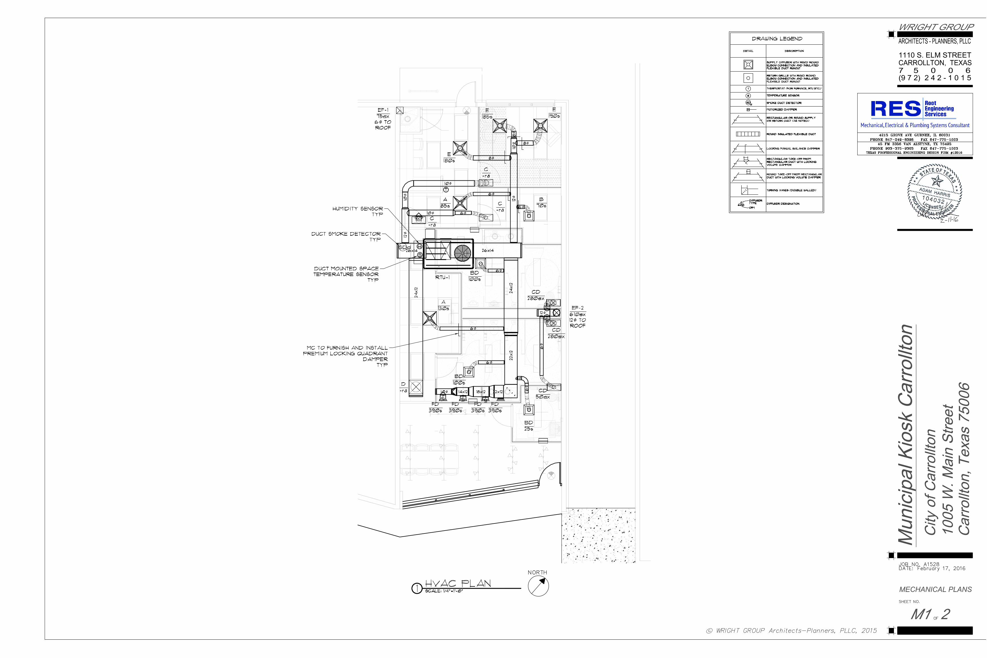
OR CONSTRUCTION
MECHANICAL PLANS

OR CONSTRUCTION
MECHANICAL SCHEDULES
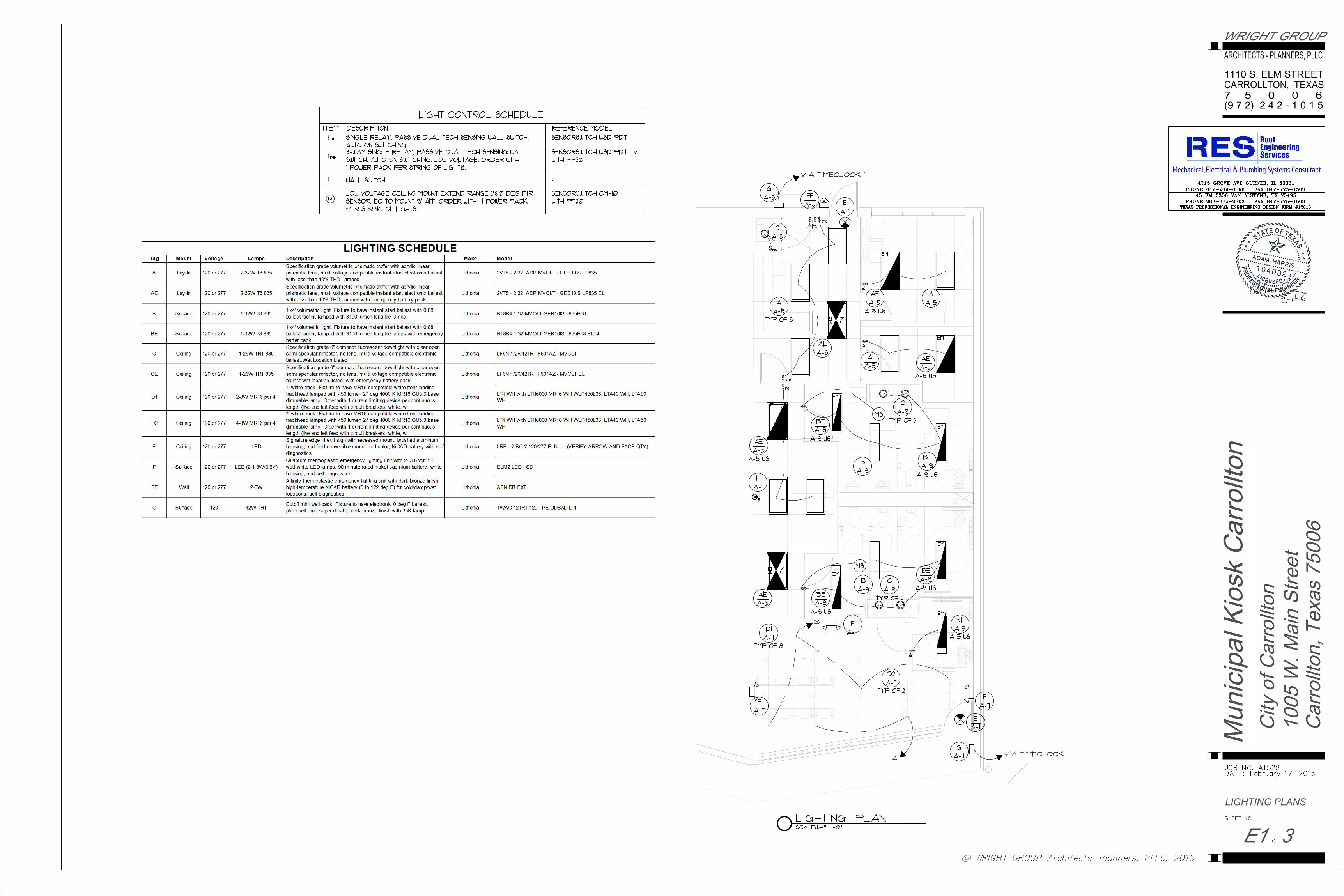
OR CONSTRUCTION
LIGHTING PLANS

OR CONSTRUCTION
ELECTRICAL PLANS
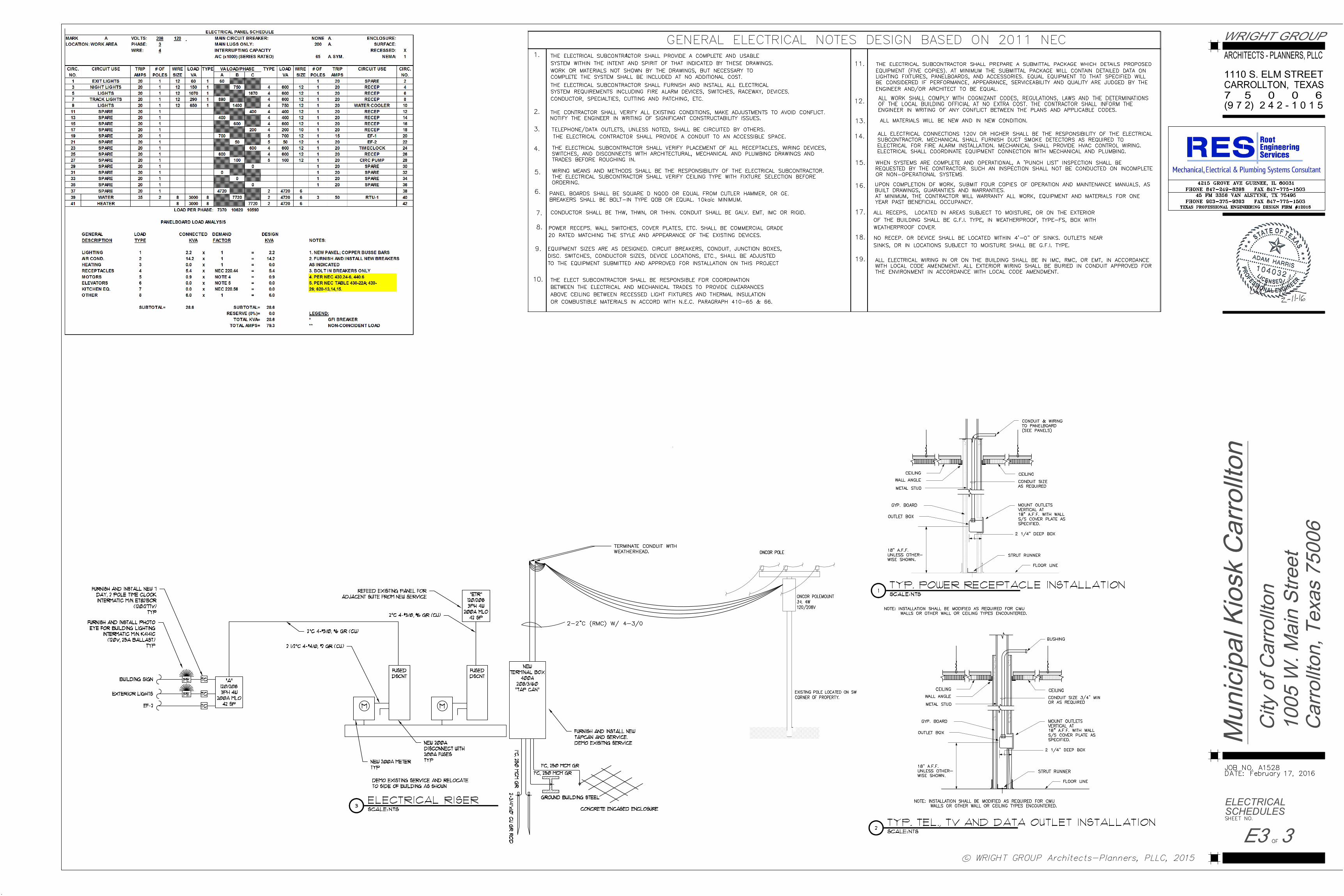
OR CONSTRUCTION
ELECTRICAL
SCHEDULES
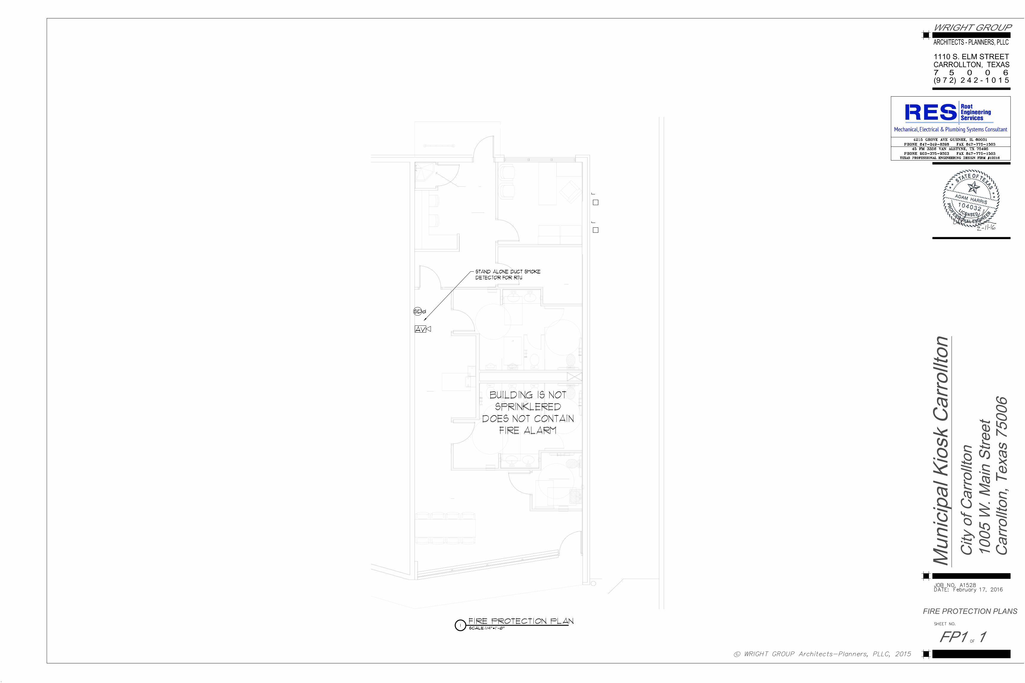
OR CONSTRUCTION
FIRE PROTECTION PLANS
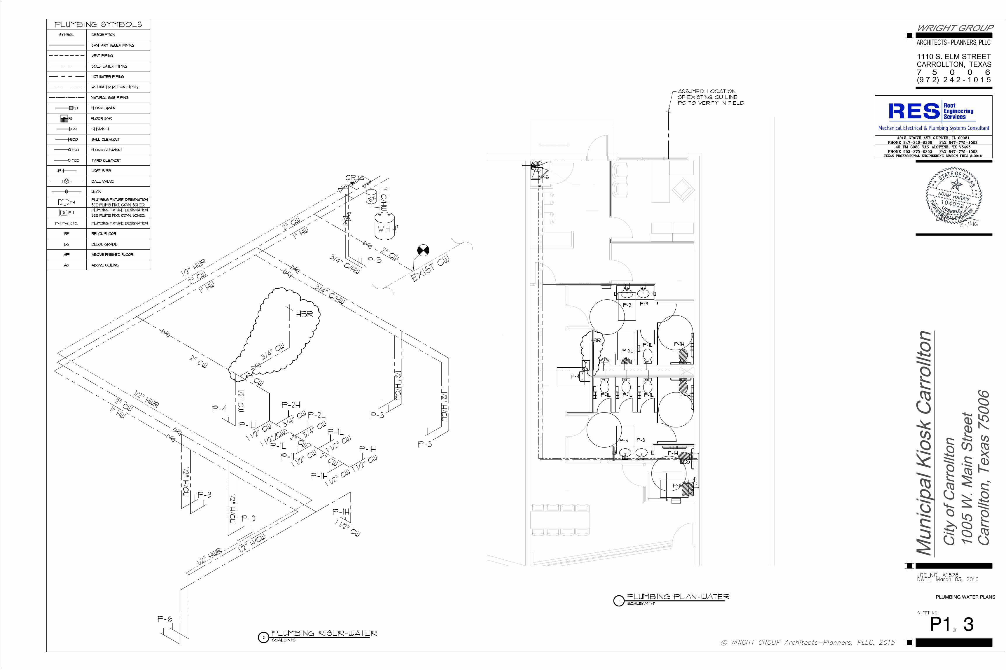
PLUMBING WATER PLANS
P1 3
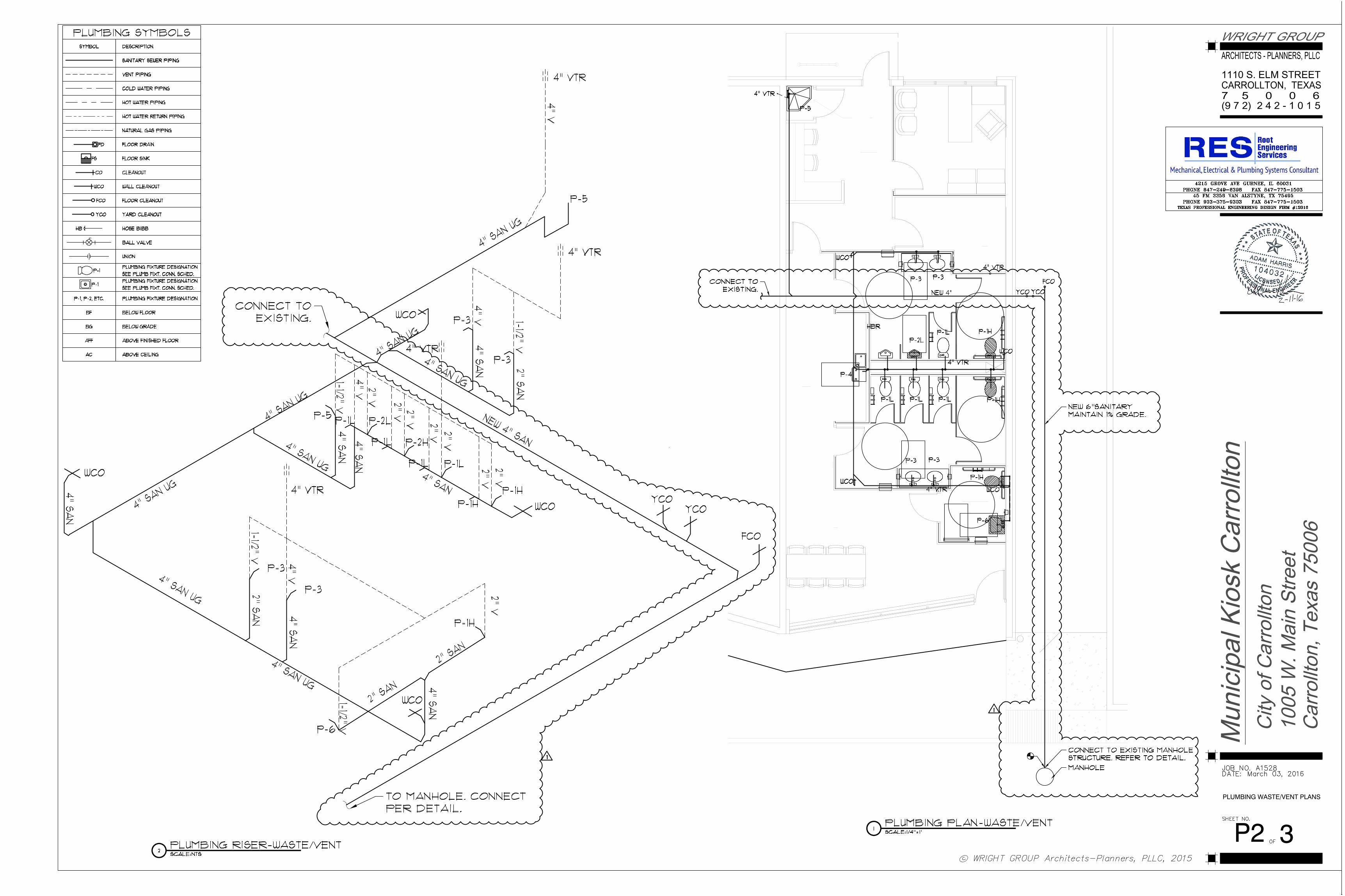
PLUMBING WASTE/VENT PLANS
P2 3
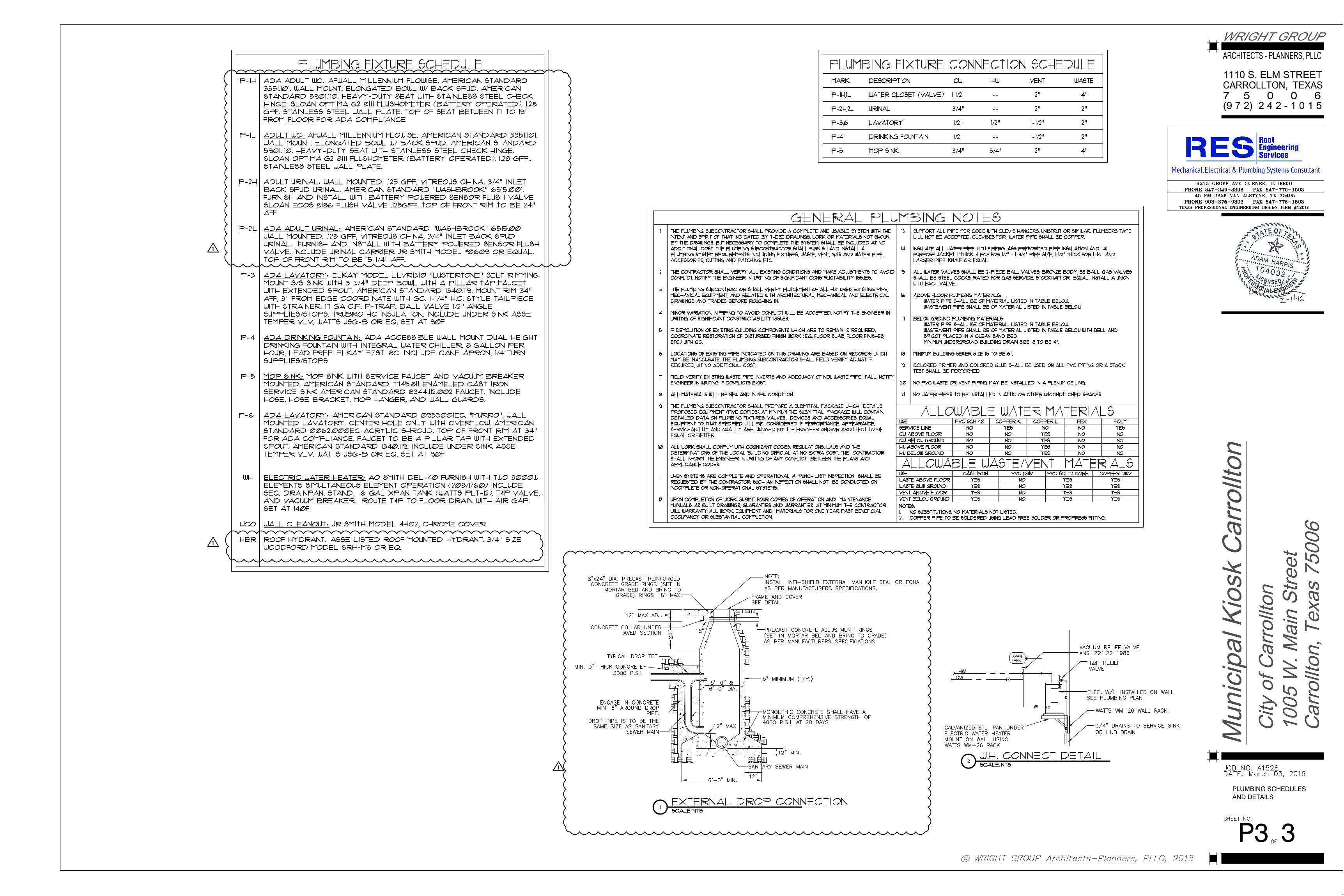
P3
PLUMBING SCHEDULESAND DETAILS
3