CITY MULTI INSTALLATION AND PRE-COMMISSIONING BOOKLET … · nitrogen purging All brazing to be...
68
CITY MULTI INSTALLATION AND PRE-COMMISSIONING BOOKLET The BDT & Mitsubishi Electric Partnership – Delivering superior technology together Since it’s founding in 1981, BDT has partnered with Mitsubishi Electric to exclusively supply their products to the New Zealand market. With over 30 years of partnership Mitsubishi Electric and BDT hold a strong relationship which recognises the importance of well trained, highly skilled technical support staff. Both companies share the belief that quality support strengthens the product by providing valuable design, installation, service and maintenance information quickly and efficiently. BDT engineers and support staff undergo regular factory training to confidently ensure that we are supplying the most up to date and quality advice. Confidential This document has been designed, and can only be used as a guide and as a singular reference tool for the Mitsubishi Electric City Multi installation project that it was intended for.
Transcript of CITY MULTI INSTALLATION AND PRE-COMMISSIONING BOOKLET … · nitrogen purging All brazing to be...

CITY MULTI INSTALLATION AND
PRE-COMMISSIONING BOOKLET
The BDT & Mitsubishi Electric Partnership – Delivering superior technology together
Since it’s founding in 1981, BDT has partnered with Mitsubishi
Electric to exclusively supply their products to the New Zealand
market. With over 30 years of partnership Mitsubishi Electric and
BDT hold a strong relationship which recognises the importance of
well trained, highly skilled technical support staff. Both companies
share the belief that quality support strengthens the product by
providing valuable design, installation, service and maintenance
information quickly and efficiently. BDT engineers and support staff
undergo regular factory training to confidently ensure that we are
supplying the most up to date and quality advice.
Confidential
This document has been designed, and can only be used as a guide
and as a singular reference tool for the Mitsubishi Electric City
Multi installation project that it was intended for.

This document is designed to outline BDT’s installation and pre-commissioning expectations and in turn provide a guide to ensure that an effective commissioning process can be undertaken to minimise potential delays. It is recommended that both the project manager and the onsite supervisor/manager familiarise themselves with these guidelines prior to calling BDT staff out to commence the actual commissioning process on-site. If BDT attends site to commission the new system and find that the pre-commissioning expectations have not been met as per the guidelines outlined in this document; BDT reserves the right to leave site to attend to other commitments and return once the pre-commissioning expectations have been completed. If the installer is unable to complete the pre-commissioning process, BDT also reserves the right to submit charges to cover our costs of returning to site and/or assisting with bringing the system up to a commissionable standard. These costs may include additional flights, accommodation, travel time, parts and labour onsite. These charges are additional to the actual commissioning cost charged at the time of purchase of the product. Labour charges will be set at $75.00 + GST per hour.
This booklet has been prepared on the basis of the latest product and system specifications at the time of booklet publication. It is intended as a guide and should not be relied upon when designing system installations. From time to time models, dimensions and specifications change so differences may exist between the content of this manual and final product specifications.
Always check the BDT website or contact Technical Services on (0800 163 526) to confirm current product data before carrying out any prescribed work.
The contents and instructions within this booklet do not in any way negate local bylaws or New Zealand standards and regulations, nor does it remove the requirement for installers and/or service persons to be suitably qualified to legitimately carry out the prescribed work. Please always confirm and comply with your local regulations before carrying out any prescribed installation or service work.
Statement of Confidentiality
All content included in this document is the property of Black Diamond Technologies Limited and Mitsubishi Electric Corporation Japan. Parts of this information are protected by international copyright laws. This information must remain confidential and may not be reproduced, modified, republished, distributed, transmitted, displayed, broadcast or otherwise exploited in any manner without the express prior written permission of BDT. This document has been designed, and can only be used as a guide and as a singular reference tool for the Mitsubishi Electric City Multi installation project that it was intended for.
As this publication is intended as a guide and is considered reference material, in no event will Black Diamond Technologies Limited be held liable for any damages including, without limitation, direct, indirect, special, incidental, consequential or punitive damages or expenses arising for the misinterpretation/misapplication of the recommended practices outlined herein.
CONTENTS
SECTION AInstallation Requirements and Procedures
Practice Piping Procedure
Twinning Kit Piping
Piping Limitations
Outdoor Unit Spacing
Mounting of Outdoor Units
Wiring Procedure
Power Supply Indoor and Outdoor Units
Inputs and Outputs
M-Net Wiring Procedure
M-Net Addressing
Piping and Wiring Schematics
Additional Refrigerant Calculations
Dip Switches
Auto Changeover
Indoor Unit Installation Setting Template
SECTION BInstallation and Commissioning Focus(Back page in sleeve)
Pre-commissioning Site Inspection Form
Pre-commissioning Check Sheet
Indoor Unit Installation Setting
Project Piping and Wiring Schematics
04
07
14
24
27
31
32
40
43
46
49
51
56
66
67

4
01. PIPE RUN PLANNING
Planning of pipe runs should take into account the following criteria:
NOTE: Non-compliant pipe work will void the warranty.
02. NITROGEN PURGING
All brazing to be done with OFN (oxygen-free nitrogen) purging through the pipe work system.
Nitrogen should be circulated into the pipe work branches and are to be welded using a flow regulator. This prevents oxidation
of the inside of the pipe surface. This oxidation can block filters and LEV valve orifices, and cause oil contamination and
compressor failure.
ALL BRAZING MUST BE CARRIED OUT USING DRY NITROGEN PURGING.
NOTE: Failure to follow this guideline will void the warranty.
PRACTICE PIPING PROCEDURE [R410A]
Nominal Diameter Outside Diameter (mm)
R22/R407Cmm across flare face
R410Amm across flare face
1/4”
3/8”
1/2”
5/8”
3/4”
6.35
9.52
12.7
15.88
19.05
9
13
16.2
19.4
23.3
9.1
13.2
16.6
19.7
----
PIPE:
All pipe used in R410A installations is to comply with
AS/NZ Standard 1677 Part 2. Copper tube of the correct
wall thickness must be used.
SEALED PIPE: Hard and soft drawn copper tube stored on site prior to
installation must have plastic end caps fitted to prevent
ingress of moisture and foreign objects. Bends and fittings
should be kept dry and in the original packing prior to
installation.
PENETRATIONS: All building penetrations should be made in such a way that
the bare copper pipe does not contact the building fabric.
BENDS:Minimise the number of bends. Ensure all soft drawn bends
are made with the correct size benders and are of full internal
diameter.
PIPE CLAMPS: Ensure that the pipe work is fixed so there is no tension on
the indoor or outdoor unit connections. This can lead to stress
fractures at the flare/flange.
PIPE RUN LENGTHS: Ensure the maximum pipe run lengths comply with system
specifications.
03. FLARE / FLANGE JOINTING PROCEDURE
R410A operates at much higher pressures than R22 and R407C refrigerants.
For this reason copper flare connection dimensions must meet the following criteria:

5
R410A flare nuts must also be used. Failure to do so can cause joint failure and refrigerant loss.
Prior to connecting flange and flare connections oil should be applied to the mating faces. Failure to do this causes tearing of
the copper flare surface. This causes leaking joints and joint failure due to material stress. The use of oil on connections also
allows the correct torque to be applied to the flare nut without pipe damage occurring.
Alkyl benzene oil is to be used to lubricate the connections. Alkyl benzene oil is hygroscopic (absorbs moisture) and should be
kept in an air tight container. The use of mineral based oil is not permitted as it contaminates the oil system and causes sludge
to form.
04. DAILY SECTIONAL SYSTEM PRESSURING
During installation of multiple circuit systems, it is recommended that at the end of each day, the pipe work be left pressurised
and any pressure loss be investigated prior to commencement of further piping the next day.
This procedure performs two functions:
1. Isolates any leaks to a small section of piping making it easier to trace and repair.
2. Pressurised pipe work prevents moisture and other foreign objects from entering the pipe work.
It is easier to pressurise the indoor units from the BC connection boxes.
NOTE: Please ensure that both vapour and liquid connections are pressurised (looped) otherwise damage to indoor LEVs can occur.
Risers can be capped prior to the BC boxes and pressurised from the outdoor unit service valve connections.
Pressure for overnight testing to 100 psi using dry nitrogen.
A final system pressure test of 500 psi using dry nitrogen held for 24 hours is required to prove complete system tightness prior
to evacuation. The results must be noted.
05. EFFECTIVE EVACUATION TECHNIQUES
• Effective evacuation technique at time of installation is a primary contributor to the long and trouble-free operation of a refrigerant system. The downstream effects of moisture in a system can vary and include valve blockages, high head pressures, oil sludging to copper plating of compressor internal parts and eventual compressor failures.
• Triple Evacuation Method must be used when evacuating the system prior to commissioning. The vacuum values reached at each stage of evacuation must be noted on the pre-commissioning sheet contained in this booklet.
• Both the initial and second evacuation must be carried out with the schraedar valve cores removed. This allows the vacuum pump to work more effectively at removing any moisture, and allows the dry nitrogen purges to be released quicker. Core removal tools and vacuum charge valves are available, and allow the cores to be removed on the final evacuation.
• A check valve must be fitted to the vacuum pump to prevent the vacuum pump oil being sucked into the City Multi system if the power is removed from the vacuum pump.
NOTE: Most vacuum pump oil is mineral-based and this is incompatible with the synthetic-based oil in the City Multi system.

6
• A two-stage vacuum pump with fresh vacuum pump oil capable of a vacuum of 50 microns should be selected. Where possible it is best engineering practice to have a pump specifically for installations rather than the service pumps which tend to deteriorate during service tasks.
• Using a 3/8” connection line to the manifold is important to allow quicker vapour volume removal.
• An accurate vacuum gauge is an essential tool to gauge the system tightness and the effectiveness of the evacuation procedure. A vacuum of 1000 microns should be reached on the initial vacuum test. A rapid rise indicates a leak is present. A small, slow rise indicates the possible presence of moisture. The slow rise is due to the moisture molecules slowly detaching from the pipe surface and starting to expand in the vacuum void. This is why the vacuum must be held for a time. Installation time and commissioning schedules often affect the time available for the ideal vacuum procedure. It cannot be reinforced enough that an effective vacuum process is critical to the system’s long term operation and warranty compliance.
• When possible it is preferable to use copper lines for evacuation purposes, as gauge hoses are porous when trying to measure accurate deep vacuum.
VACUUM MEASUREMENT COMPARISONS
1 TORR = 1mm HG
1 TORR 1000 = 1000 microns
microns 1000 = 29.88” HG (inches or mercury)
microns = 1mm HG
1. Connect the vacuum pump, check valve, vacuum gauge, charge line with the access cores removed and pull an initial vacuum of 1000 microns. Hold vacuum for 1 to 2 hours and monitor.
2. Break vacuum with dry nitrogen to 1 to 2 bars and release nitrogen.
3. Evacuate to 500 microns or less. Hold and monitor for 1 to 2 hours.
4. Break vacuum with dry nitrogen to 1 to 2 bars and release nitrogen.
5. Refit access valve cores. Evacuate down to best vacuum as close to 200 microns as possible. Hold for 8 hours.
6. Add additional refrigerant while system is under vacuum (as calculated from pipe lengths). Open outdoor unit isolation valves. System should now be ready for commissioning.
06. RECOMMENDED TRIPLE EVACUATION PROCEDURE
NOTE: BDT reserves the right to cut sections of pipe open and inspect if there is any doubt dry nitrogen has not been purged through the pipe work during the welding of any copper connections.

7
Correct piping of the twinning kit is essential to the performance and safety of the equipment
installed. It is critical that the instructions below are followed closely as incorrect piping can lead to
performance loss and/or catastrophic failure of the compressor.
Outdoor unit 2Outdoor unit 1
High-pressure twinning pipe
200mm [7-7/8 in.] max.
To BC controller
Twinning pipe (low-pressure side)
Twinning pipe (high-pressure side)
On-site piping (low-pressure connecting pipe: between outdoor units)
On-site piping (low-pressure main pipe: to BC controller)
On-site piping (high-pressure main pipe: to BC controller)
Straight run of pipe that is 500 mm [19-11/16 in.] or more
See the Installation Manual for the details of Twinning pipe installation.
See the following drawing for connecting the pipes between the outdoor units.
Twinning on the outdoor unit side
R2 SERIES TWINNING KIT PIPING

8
R2 SERIES TWINNING KIT PIPING (CONTINUED)
Refrigerant pipe routing
Installation
· P200, 250, EP200, 250
· EP400, 450
(5-29/32) (3-23/32)150 × 94 Knockout hole
Specifications
For pipes Bottom through hole
UsageNO.
For wires(2-1/16)
(2-9/16)Ø52 Knockout hole
Ø65 Knockout holeBottom through hole
Bottom through hole
A
C
B
(Unit: mm [in.])
Installation base perpendicular to the unit’s front panelInstallation base parallel to the unit’s front panel
· P300, 350, EP300, 350
When the pipes and/or cables are routed at the bottom of the unit, make sure that the through hole at the base ofthe unit does not get blocked with the installation base. When the pipes are routed at the bottom of the unit, the base should be at least 100 mm [3-15/16 in.] in height.
The figure above shows a unit on which a low-pressure twinning pipe kit is not installed.
The gaps around the edges of through holes for pipes and wires on theunit allow water or mice to enter the unit and damage its parts. Closethese gaps with filler plates.
This unit allows two types of pipe routing:• Bottom piping• Front piping
To prevent small animals, water and snow fromentering the unit and damaging its parts, close the gap around the edges of through holes for pipes and wires with filler plates.
CAUTION
Fill the gap at the siteExample of closure materials (field supply)
681(
678~
684)
29.5
(740
)
29.5
8076080
177222 051
121
196
9484
BA
C
(Mou
ntin
g pi
tch)
2×2-14×31 Oval hole 2×2-14×20 Oval hole
Bottom view(Mounting pitch)
(without detachable leg)
B
CA
(Mounting pitch)
(Mou
ntin
g pi
tch)
Bottom view
2×2-14×31 Oval hole2×2-14×20 Oval hole
681(
678~
684)
5.925.92
80106080
121
196
(740
)
227272 150
8494
(without detachable leg)
516561 150
84
121
196
80 795 795 80
29.5
29.5
(740
)94BA
C
(Mounting pitch) (Mounting pitch) Bottom view
681(
678~
684)
(Mou
ntin
g pi
tch)
2×3-14×31 Oval hole 2×3-14×20 Oval hole(without detachable leg)

9
4 - 115
4. Outdoor Installation AN1 2nd
S.D. R
2
MEE14K009
4-3-6. Twinning on the outdoor unit side
• The pipe from multiple outdoor units must be installed so that oil will not accumulate in the pipe under certain conditions. Refer to the figures below for details.* Small dots in the figures indicate branching points.
In an R2 system: To a BC controller
(1) The pipe from the outdoor units must be inclined downward to the indoor unit side. In the figure on the right, because the pipe is inclined upward, the oil in the pipe accumulates when Unit 1 is in operation and Unit 2 is stopped.
(2) The distance between the unit bottom and the pipe (H) must be 0.2 m (7-7/8 in) or below. In the figure on the right, because the distance is more than 0.2 m (7-7/8 in), the oil accumulates in Unit 1 when Unit 2 is in operation and Unit 1 is stopped.
H
H
(3) The vertical separation between units (H) must be 0.1 m (3-15/16 in) or below. In the figure on the right, because the distance is more than 0.1 m (3-15/16 in), the oil accumulates in Unit 1 when Unit 2 is in operation and Unit 1 is stopped.
H
H
(4) The vertical separation between units (H) must be 0.1 m (3-15/16 in) or below. In the figure on the right, because the distance is more than 0.1 m (3-15/16 in), the oil accumulates in Unit 2 when Unit 1 is in operation and Unit 2 is stopped.
H
H
• Make sure that the inclination tolerance of the Twinning Kit is ±15˚ to the ground to avoid unit damage.
±15°
Twinning Kit
• Do not install traps to prevent oil backflow and compressor start-up failure.
Unit 2Unit 1 Unit 2Unit 1
Unit 2
Unit 2
Unit 1
Unit 1
H ≤ 0.2 m (7-7/8 in)
Unit 2Unit 1
H > 0.2 m (7-7/8 in)
Unit 1
Unit 2
Unit 1
H ≤ 0.1 m (3-15/16 in)
Unit 2
Unit 1
H > 0.1 m (3-15/16 in)
Unit 1
Unit 2
Unit 1
H ≤ 0.1 m (3-15/16 in)
Unit 2
Unit 1
H > 0.1 m (3-15/16 in)
A
AA
AA
AA
A
AA
A
A
0000003417.BOOK 115 ページ 2014年10月22日 水曜日 午前10時35分

10
Correct piping of the twinning kit is essential to the performance and safety of the equipment
installed. It is critical that the instructions below are followed closely as incorrect piping can lead to
performance loss and/or catastrophic failure of the compressor.
The length of the straight pipe must be 500mm[19-11/16 in.] or longer.If not, it may cause improper operation.
CAUTION
Field piping
Twinning kit
Twinning kitField piping
Field piping
Field piping
Twinning kit
The length of the straight pipe
must be 500 mm [19-11/16 in.] or longer
The length of the straight pipe
must be 500 mm [19-11/16 in.] or longer
The length of the straight pipe
must be 500 mm [19-11/16 in.] or longer
See the following drawing for connecting the pipes between the outdoor units.
<In case of 2 unit combination>
<In case of 3 unit combination>
Twinning on the outdoor unit side
Field piping
Y SERIES TWINNING KIT PIPING

11
4 - 55
S.D. Y
MEE14K009
4. Outdoor Installation AN1 2nd
To indoor unitTwinning pipe 1
200mm [7-7/8 in.]or less
200mm [7-7/8 in.]or less
Outdoor unit1 Outdoor unit 2
Outdoor unit 1 Outdoor unit 2 Outdoor unit 3
Twinning pipe 1 Twinning pipe 2
To Indoor unit
<PUHY-P400YSKB-A><PUHY-EP500YSLM-A>
<PUHY-P950YSKB-A><PUHY-EP800YSLM-A>
0000003416.BOOK 55 ページ 2014年11月11日 火曜日 午前9時34分

12
Y SERIES TWINNING KIT PIPING (CONTINUED)
Refrigerant pipe routing
Installation
·P200, 250 EP200, 250
·P450 EP400, 450
· P300, 350, 400 EP300, 350
Installation base perpendicular to the unit’s front panelInstallation base parallel to the unit’s front panel
When the pipes and/or cables are routed at the bottom of the unit, make sure that the through hole at the base ofthe unit does not get blocked with the installation base. When the pipes are routed at the bottom of the unit, the base should be at least 100 mm [3-15/16 in.] in height.
(Unit : mm [in.])
Bottom view
Bottom view
Bottom view
(5-29/32) (3-23/32)150 × 94 Knockout hole
Specifications
For pipes Bottom through hole
UsageNO.
For wires(2-1/16)
(2-9/16)Ø52 Knockout hole
Ø65 Knockout holeBottom through hole
Bottom through hole
The gaps around the edges of through holes for pipes and wires on theunit allow water or mice to enter the unit and damage its parts. Closethese gaps with filler plates.
This unit allows two types of pipe routing:• Bottom piping• Front piping
To prevent small animals, water and snow fromentering the unit and damaging its parts, close the gap around the edges of through holes for pipes and wires with filler plates.
CAUTION
Fill the gap at the siteExample of closure materials (field supply)
A
C
B
BA
C
2×2-14×31 Oval hole 2×2-14×20 Oval hole(without detachable leg)
(Mou
ntin
g pi
tch)
68
1(67
8~68
4)29
.5
(740
)
29.5
80(Mounting pitch)
76080
177222 051
121
196
9484
B
CA
(Mounting pitch)
(Mou
ntin
g pi
tch)
2×2-14×31 Oval hole2×2-14×20 Oval hole(without detachable leg)
681(
678~
684)
5.925.9280106080
121
196
(740
)
227272 150
8494
516561 150
84
121
196
80 795 795 80
29.5
681(
678~
684)
29.5
(740
)94BA
C
(Mounting pitch) (Mounting pitch)
(Mou
ntin
g pi
tch)
2×3-14×31 Oval hole 2×3-14×20 Oval hole(without detachable leg)

13
Twinning on the outdoor unit side
Twinning pipe
±15°
The tilt angle of the twinning pipe should be within ±15°with the horizontal plane.
Note: See the following drawing for the fitting position of the twinning pipe.
The tilt angle of the twinning pipeThe tilt angle of the twinning pipe must be within ±15° with the horizontal plane. Tilting the twinning pipe more than specified will cause damage to the unit.
The length of the straight part of the pipe before the branchingFor the twinning kit, always use the accessory piping parts. The length of the straight part of pipe connected in front of the twinning pipe must be 500 mm [19-11/16 in.] or longer. (Connect the field piping so that the length of the straight part of pipe connected in front of the twinning pipe can be 500 mm [19-11/16 in.] or longer.) If the length is less than 500 mm [19-11/16 in.], it will cause damage to the unit.
To Indoor unit
Less than 2 m [6 ft.]
To Indoor unit2m [6 ft.]
200 mm [7-7/8 in.] or over
Trap (gas pipe only)
Precautions for outdoor unit combinations
<2 m [6 ft.] or less> <More than 2 m [6 ft.]>
Caution:Do not install traps other than the ones between outdoor units described on a separate sheet to prevent oil backflow and compressor start-up failure. Do not install solenoid valves to prevent oil backflow and compressor start-up failure. Do not install a sight glass because it may show improper refrigerant flow. If a sight glass is installed, inexperienced technicians that use the glass may overcharge the refrigerant.
•••
<A> Install the piping so that oil will not accumulate in the stopped outdoor unit.
1.unit 1 unit 2 unit 3 unit 1 unit 2 unit 3
unit 1 unit 2 unit 3
The NG example shows that oil accumulates because the units are installed on a reverse gradient while unit 1 is in operation, and unit 3 is stopped.
2.
unit 1 unit 2 unit 3
unit 1 unit 2 unit 3
h1
h1 = 0.2 m (7-7/8 in) max
h1
h1 > 0.2 m (7-7/8 in)The NG example shows that oil accumulates into units 1 and 2 while unit 3 is in operation, and units 1 and 2 are stopped. Vertical pipe height (h) should be 0.2 m (7-7/8 in) or below.
3. unit 1
unit 2 unit 3
unit 3
h2 h2 = 0.1 m (3-15/16 in) max
unit 1
unit 2 unit 3
h2h2 > 0.1 m (3-15/16 in)
The NG example shows that oil accumulates into unit 1 while unit 3 is in operation, and unit 1 is stopped. Vertical pipe height (h) should be 0.2 m (7-7/8 in) or below.
4.
unit 1 unit 2
h2 = 0.1 m (3-15/16 in) max
h2
h2 > 0.1 m (3-15/16 in)
The NG example shows that oil accumulates into unit 3 while unit 1 is in operation, and unit 3 is stopped. Vertical pipe height (h) should be 0.2 m (7-7/8 in) or below.
<B> When the piping on the outdoor unit side (from the twinning pipe) exceeds 2 m [6 ft], ensure a trap (gas pipe only) within 2 m [6 ft]. Make sure the height of the trap is 200 mm [7-7/8 in] or more.If there is no trap, oil can accumulate inside the pipe, causing a shortage of oil and possible damage to the compressor.
To Indoor unitTo Indoor unit
Twinning pipe Twinning pipeTwinning pipe Twinning pipe
Downward slopeUpward slope
unit 3
unit 1 unit 2
h2

14
R2 SERIES PIPING LIMITATIONS
3-2. Piping Design3-2-1. If 16 ports or less are in use, I.e., if only one BC controller is in use with no sub BC controller
PURY-P-YLM
Table 3-2-1-1. Piping length limitation Table3-2-1-2. Bent equivalent length "M"Item Piping in the figure Max. length Max. equivalent length Outdoor Model M (m/bent [ft./bent])Total piping length A+B+a+b+c+d *1 - P200YLM 0.35 [1.15']Farthest IU from OU A+B+d 165 [541'] 190 [623'] P250YLM 0.42 [1.38']Distance between OU and BC A 110 [360'] *1 110 [360'] *1 P300YLM
P350YLM0.42 [1.38']
Farthest IU from BC controller B+d 40 [131'] *2*3 40 [131'] *3 0.47 [1.54']Heignt between OU and IU (OU above IU) H 50 [164'] *5 -Heignt between OU and IU (OU under IU) H' 40 [131'] *6 -Height between IU and BC h1 15 [49'] (10 [32']) *4 -Height between IU and IU h2 15 [49'] (10 [32']) *4 -
Fig. 3-2-1-1 Piping length and height between IU and BC controllerTable3-2-1-3. Piping "A"size selection rule (mm [in.])
(m [ft.])
Outdoor Model Pipe(High pressure) Pipe(Low pressure)P200YLM ø15.88 [5/8"] ø19.05 [3/4"]P250YLM ø19.05 [3/4"] ø22.20 [7/8"]P300YLMP350YLM
ø19.05 [3/4"] ø22.20 [7/8"]ø19.05 [3/4"] ø28.58 [1-1/8"]
Table3-2-1-4. Piping "B" size seleciton rule (mm [in.])Total down-stream Indoor capacity Pipe(Liquid) Pipe(Gas)P140 or less ø9.52 [3/8"] ø15.88 [5/8"]
Table3-2-1-5. Piping "a", "b", "c", "d" size selection rule (mm [in.])Indoor Unit size Pipe(Liquid) Pipe(Gas)P15 to P50, GUF-50RD(H) ø6.35 [1/4"] ø12.70 [1/2"]P63 to P140, GUF-100RD(H) ø9.52 [3/8"] ø15.88 [5/8"]
]"4/3[ 50.91ø]"8/3[ 25.9ø002P]"8/7[ 02.22ø]"8/3[ 25.9ø052P
Note1. No Header usable on PURY system.Note2. Indoor unit sized P100-P250 should be connected to BC controller via Y shape joint CMY-R160-J1 ;Note3. Indoor unit sized P100-P250 does NOT share BC controller ports with other Indoor units ;Note4. As bends cause pressure loss on transportation of refrigerant, fewer bends design is better ;
Piping length needs to consider the actual length and equivalent length which bends are counted.Equivalent piping length (m)=Actual piping length+"M" x Number of bends.
Note5. Set DIP-SW 4-6 to ON of BC controller, in case of connected Indoor unit sized P100-P140 with 2 ports.Note6. It is also possible to connect Indoor unit sized P100-P140 with 1 port (set DIP-SW 4-6 to OFF).
Note7. Individual indoor units grouped together to connect to the BC controller via one port cannot operateindividually in heating and cooling modes at the same time. I.e., they must all function in either heating
However, the cooling capacity decreases a little (For details, refer to the chapter OUTDOOR UNITS,R2 SERIES, 6-4. Correction by port counts of the BC controller).
or cooling together.Note8. Indoor capactiy is described as its model size. For example, PEFY-P63VMA-E, its capacity is P63.Note9. Total down-stream Indoor capacity is the summary of the model size of Indoors down-stream.
Note10. To enable the continuous heating mode, set SW4 (848) to ON.For example, PEFY-P63VMA-E + PEFY-P32VMA-E : Total Indoor capacity = P63 + P32 = P95.
OU : Outdoor Unit ; IU : Indoor Unit ; BC : BC controller*1. Refer to the section 3-2-7.*2. Details refer to Fig.3-2-1-1*3. Farthest Indoor from BC controller "B+d" can exceed 40m till 60m if no Indoor sized P200, P250 connected. Details refer to Fig.3-2-1-1*4. Distance of Indoor sized P200, P250 from BC must be less than 10m, if any.*5. 90m is available depending on the model and installation conditions. For more detailed information, contact your local distributor.*6. 60m is available depending on the model and installation conditions. For more detailed information, contact your local distributor.
0
10
20
30
40
50
60
70
0 5 10 15Height difference between the main BC controller
and indoor unit (m)
Pipe
leng
th b
etw
een
the
mai
n BC
cont
rolle
r and
indo
or u
nit (
m)
(P100-250)
BC controller
a b
H H'
h1
IU(P15-P80)
Joint(CMY-R160-J1)
IU
Joint(CMY-Y102SS-G2)
Max.3 sets for 1 port.Total capacity <= P80
B
c
d
IU
A
OU
Reducer (P15~P50)(attached with BC controller)
IU
h2
For outodoor units equal to or larger than a size P400, onthe BC controller please ensure CMB-P•V-GA1 is used.
S T
M
N
CMY-R160-J1(Gas side) IU
CMY-R160-J1(Liquid side)
BC controller
Fig. 3-2-1AA
Fig. 3-2-1A Piping scheme
(T)ø19.05ID
(N)ø9.52ID(M)ø3/8"(Brazing)
(M)ø3/8"(Brazing)
(S)ø5/8"(Brazing)
(S)ø5/8"(Brazing)
226
226
Joint CMY-R160-J1 Gas side
Joint CMY-R160-J1 Liquid side

15
3. Piping Design AN1 2nd
3-2-2. If 16 ports or less are in use, I.e., if only one BC controller is in use with no sub BC controllerPURY-EP-YLM
Table 3-2-1-1. Piping length limitation Table3-2-1-2. Bent equivalent length "M"Item Piping in the figure Max. length Max. equivalent length Outdoor Model M (m/bent [ft./bent])Total piping length A+B+a+b+c+d *1 - EP200YLM 0.35 [1.15']Farthest IU from OU A+B+d 165 [541'] 190 [623'] EP250YLM 0.42 [1.38']Distance between OU and BC A 110 [360'] *1 110 [360'] *1 EP300YLM
EP350YLM0.42 [1.38']
Farthest IU from BC controller B+d 40 [131'] *2*3 40 [131'] *3EP400YLM
0.47 [1.54']Heignt between OU and IU (OU above IU) H 50 [164'] *5 -
EP450YLM 0.50 [1.64']0.50 [1.64']
Heignt between OU and IU (OU under IU) H' 40 [131'] *6 -Height between IU and BC h1 15 [49'] (10 [32']) *4 -Height between IU and IU h2 15 [49'] (10 [32']) *4 -
Fig. 3-2-1-1 Piping length and height between IU and BC controllerTable3-2-1-3. Piping "A"size selection rule (mm [in.])
(m [ft.])
Outdoor Model Pipe(High pressure) Pipe(Low pressure)EP200YLM ø15.88 [5/8"] ø19.05 [3/4"]EP250YLM ø19.05 [3/4"] ø22.20 [7/8"]EP300YLMEP350YLM
ø19.05 [3/4"] ø22.20 [7/8"]
EP400YLMø19.05 [3/4"] ø28.58 [1-1/8"]
EP450YLM ø22.20 [7/8"] ø28.58 [1-1/8"]ø22.20 [7/8"] ø28.58 [1-1/8"]
Table3-2-1-4. Piping "B" size seleciton rule (mm [in.])Total down-stream Indoor capacity Pipe(Liquid) Pipe(Gas)P140 or less ø9.52 [3/8"] ø15.88 [5/8"]
Table3-2-1-5. Piping "a", "b", "c", "d" size selection rule (mm [in.])Indoor Unit size Pipe(Liquid) Pipe(Gas)P15 to P50, GUF-50RD(H) ø6.35 [1/4"] ø12.70 [1/2"]P63 to P140, GUF-100RD(H) ø9.52 [3/8"] ø15.88 [5/8"]
]"4/3[ 50.91ø]"8/3[ 25.9ø002P]"8/7[ 02.22ø]"8/3[ 25.9ø052P
Note1. No Header usable on PURY system.Note2. Indoor unit sized P100-P250 should be connected to BC controller via Y shape joint CMY-R160-J1 ;Note3. Indoor unit sized P100-P250 does NOT share BC controller ports with other Indoor units ;Note4. As bends cause pressure loss on transportation of refrigerant, fewer bends design is better ;
Piping length needs to consider the actual length and equivalent length which bends are counted.Equivalent piping length (m)=Actual piping length+"M" x Number of bends.
Note5. Set DIP-SW 4-6 to ON of BC controller, in case of connected Indoor unit sized P100-P140 with 2 ports.Note6. It is also possible to connect Indoor unit sized P100-P140 with 1 port (set DIP-SW 4-6 to OFF).
Note7. Individual indoor units grouped together to connect to the BC controller via one port cannot operateindividually in heating and cooling modes at the same time. I.e., they must all function in either heating
However, the cooling capacity decreases a little (For details, refer to the chapter OUTDOOR UNITS,R2 SERIES, 6-4. Correction by port counts of the BC controller).
or cooling together.Note8. Indoor capactiy is described as its model size. For example, PEFY-P63VMA-E, its capacity is P63.Note9. Total down-stream Indoor capacity is the summary of the model size of Indoors down-stream.
For example, PEFY-P63VMA-E + PEFY-P32VMA-E : Total Indoor capacity = P63 + P32 = P95.
OU : Outdoor Unit ; IU : Indoor Unit ; BC : BC controller*1. Refer to the section 3-2-7.*2. Details refer to Fig.3-2-1-1*3. Farthest Indoor from BC controller "B+d" can exceed 40m till 60m if no Indoor sized P200, P250 connected. Details refer to Fig.3-2-1-1*4. Distance of Indoor sized P200, P250 from BC must be less than 10m, if any.*5. 90m is available depending on the model and installation conditions. For more detailed information, contact your local distributor.*6. 60m is available depending on the model and installation conditions. For more detailed information, contact your local distributor.
0
10
20
30
40
50
60
70
0 5 10 15Height difference between the main BC controller
and indoor unit (m)
Pipe
leng
th b
etw
een
the
mai
n BC
cont
rolle
r and
indo
or u
nit (
m)
(P100-250)
BC controller
a b
H H'
h1
IU(P15-P80)
Joint(CMY-R160-J1)
IU
Joint(CMY-Y102SS-G2)
Max.3 sets for 1 port.Total capacity <= P80
B
c
d
IU
A
OU
Reducer (P15~P50)(attached with BC controller)
IU
h2
For outodoor units equal to or larger than a size P400, onthe BC controller please ensure CMB-P•V-GA1 is used.
S T
M
N
CMY-R160-J1(Gas side) IU
CMY-R160-J1(Liquid side)
BC controller
Fig. 3-2-1AA
Fig. 3-2-1A Piping scheme
Note10. To enable the continuous heating mode, set SW4 (848) to ON.
(T)ø19.05ID
(N)ø9.52ID(M)ø3/8"(Brazing)
(M)ø3/8"(Brazing)
(S)ø5/8"(Brazing)
(S)ø5/8"(Brazing)
226
226
Joint CMY-R160-J1 Gas side
Joint CMY-R160-J1 Liquid side

16
R2 SERIES PIPING LIMITATIONS (Continued)
3-2-3. If more than 16 ports are in use, or if there is more than one BC controller in use for one outdoor unit
Table 3-2-2-1. Piping length limitation (m [ft.]) Table3-2-2-2. Bent equivalent length "M"Item Piping in the figure Max. length Max. equivalent length Outdoor Model M (m/bent [ft./bent])Total piping length A+B+C+D+E+a+b+c+d+e+f *1 - P200YLM 0.35 [1.15']Farthest IU from OU A+C+E+f 165 [541'] 190 [623'] P250YLM 0.42 [1.38']Distance between OU and BC A 110 [360'] *1 110 [360'] *1 P300YLM
P350YLM0.42 [1.38']
Farthest IU from BC controller B+d or C+D+e or C+E+f 40 [131'] *2*3 40 [131'] *2*3 0.47 [1.54']Heignt between OU and IU (OU above IU) H 50 [164'] *6 -Heignt between OU and IU (OU under IU) H' 40 [131'] *7 -Height between IU and BC h1 15 [49'] (10 [32']) *4 -Height between IU and IU h2 15 [49'] (10 [32']) *4 -Heignt between BC(Main or Sub) and BC(Sub) h3 15 [49'] (10 [32']) *5 -
Fig. 3-2-2-1 Piping length and height between IU and BC controller Table3-2-2-3. Piping "A"size selection rule (mm [in.])Outdoor Model Pipe(High pressure) Pipe(Low pressure)P200YLM ø15.88 [5/8"] ø19.05 [3/4"]P250YLM ø19.05 [3/4"] ø22.20 [7/8"]P300YLMP350YLM
ø19.05 [3/4"] ø22.20 [7/8"]ø19.05 [3/4"] ø28.58 [1-1/8"]
Table3-2-2-4. Piping "B" size seleciton rule (mm [in.])Total down-stream Indoor capacity Pipe(Liquid) Pipe(Gas)
]"8/5[ 88.51ø]"8/3[ 25.9øssel ro 041P
Table3-2-2-5. Piping "C", "D", "E" size selection rule (mm [in.])Total down-stream Indoor capacity Pipe(Lequid) Pipe(HP Gas) Pipe(LP Gas)P200 or less ø9.52 [3/8"] ø15.88 [5/8"] ø19.05 [3/4"]P201 to P300 ø9.52 [3/8"] ø19.05 [3/4"] ø22.20 [7/8"]P301 to P350 ø12.70 [1/2"] ø19.05 [3/4"] ø28.58 [1-1/8"]P351 to P400 ø12.70 [1/2"] ø22.20 [7/8"] ø28.58 [1-1/8"]P401 to P450 ø15.88 [5/8"] ø22.20 [7/8"] ø28.58 [1-1/8"]
HP : High pressure, LP:Low pressure
Table3-2-2-6. Piping "a", "b", "c", "d", "e", "f" saize selection rule (mm [in.])Indoor Unit size Pipe(Lequid) Pipe(Gas)P15 to P50, GUF-50RD(H) ø6.35 [1/4"] ø12.70 [1/2"]P63 to P140, GUF-100RD(H) ø9.52 [3/8"] ø15.88 [5/8"]P200 ø9.52 [3/8"] ø19.05 [3/4"]P250 ø9.52 [3/8"] ø22.20 [7/8"]
OU : Outdoor Unit ; IU : Indoor Unit ; BC : BC controller*1. Refer to the section 3-2-7.*2. Details refer to Fig.3-2-2-1*3. Farthest Indoor from BC controller "B+d or C+D+e or C+E+f " can exceed 40m till 60m if no Indoor sized P200, P250 connected. Details refer to Fig.3-2-2-1*4. Distance of Indoor sized P200, P250 from BC must be less than 10m, if any.*5. When using 2 Sub BC controllers, max. height "h3" should be considered.
*7. 60m is available depending on the model and installation conditions. For more detailed information, contact your local distributor.*6. 90m is available depending on the model and installation conditions. For more detailed information, contact your local distributor.
0
10
20
30
40
50
60
70
0 5 10 15Height difference between the main BC controller
and indoor unit (m)
Note1. No Header usable on PURY system.Note2. Indoor unit sized P100-P250 should be connected to BC controller via Y shape joint CMY-R160-J1 ;Note3. Indoor unit sized P100-P250 does NOT share BC controller ports with other Indoor units ;Note4. As bends cause pressure loss on transportation of refrigerant, fewer bends design is better ;
Piping length needs to consider the actual length and equivalent length which bends are counted.Equivalent piping length (m)=Actual piping length+"M" x Number of bends.
However, the cooling capacity decreases a little (For details, refer to the chapter OUTDOOR UNITS,R2 SERIES, 6-4. Correction by port counts of the BC controller).
Note5. Set DIP-SW 4-6 to ON of BC controller, in case of connected Indoor unit sized P100-P140 with 2 ports.Note6. It is also possible to connect Indoor unit sized P100-P140 with 1 port (set DIP-SW 4-6 to OFF).
Note7. Individual indoor units grouped together to connect to the BC controller via one port cannot operate individually in heating and cooling modes at the same time. I.e., they must all function in either heating or cooling together.
Note8. For sub BC controller CMB-P•V-GB1 the connectable indoor unit capacities may sum to equal that of aP350 unit or less. However, if two sub controllers are used the TOTAL sum of connectable unitsconnected to BOTH sub controllers must also not exceed that of a P350 unit.For sub BC controller CMB-P1016V-HB1 the connectable indoor unit capacities may sum to equal thator a P350 unit or less. However, if two sub controllers are used the TOTAL sum of connectable unitsconnected to BOTH sub controllers must also not exceed that of a P450 unit.
Note9. Indoor capactiy is described as its model size. For example, PEFY-P63VMA-E, its capacity is P63.Note10. Total down-stream Indoor capacity is the summary of the model size of Indoors down-stream.
Note11. To enable the continuous heating mode, set SW4 (848) to ON.For example, PEFY-P63VMA-E + PEFY-P32VMA-E : Total Indoor capacity = P63 + P32 = P95.
S T
M
N
CMY-R160-J1(Gas side) IU
CMY-R160-J1(Liquid side)
BC controller
Fig. 3-2-2AA
BC controller (Main BC)
IU
a
IU
C
b
H H'
h1h1
IU
(P15-P80) (P100-P250)
CMY-R160-J1(Joint)
IU
CMY-Y102SS-G(Joint)
Max.3 sets for 1 port.Total capacity < = P80
BC controller (Sub BC)
BC controller (Sub BC)
B
c d
IU
f
h3
D
E
CMY-Y202S-G2CMY-Y102LS-G2CMY-Y102SS-G2(Joint)
A
IUe h1
OU : Outdoor unit, IU : Indoor unit
OU
Reducer (P15-P50)(attached with BC controller) h2
Fig. 3-2-2A Piping scheme
(T)ø19.05ID
(N)ø9.52ID(M)ø3/8"(Brazing)
(M)ø3/8"(Brazing)
(S)ø5/8"(Brazing)
(S)ø5/8"(Brazing)
226
226
Joint CMY-R160-J1 Gas side
Joint CMY-R160-J1 Liquid side
Pipe
leng
th b
etw
een
the
mai
n BC
cont
rolle
r and
indo
or u
nit (
m)
PURY-P-YLM
17
Maximum pipe run
4 - 103
3. Piping Design AN1 2nd
S.D. R
2
MEE14K009
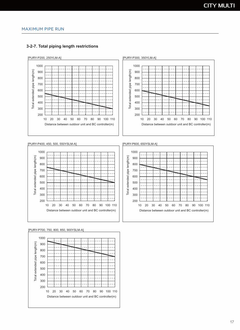
3-2-7. Total piping length restrictions
[PURY-P200, 250YLM-A] [PURY-P300, 350YLM-A]
[PURY-P700, 750, 800, 850, 900YSLM-A]
200
300
400
500
600
700
800
900
1000
10 20 30 40 50 60 70 80 90 100 110
Distance between outdoor unit and BC controller(m)
Tota
l ext
ende
d pi
pe le
ngth
(m)
200
300
400
500
600
700
800
900
1000
10 20 30 40 50 60 70 80 90 100 110
Distance between outdoor unit and BC controller(m)
Tota
l ext
ende
d pi
pe le
ngth
(m)
200
300
400
500
600
700
800
900
1000
10 20 30 40 50 60 70 80 90 100 110
Distance between outdoor unit and BC controller(m)
Tota
l ext
ende
d pi
pe le
ngth
(m)
[PURY-P400, 450, 500, 550YSLM-A]
200
300
400
500
600
700
800
900
1000
10 20 30 40 50 60 70 80 90 100 110
Distance between outdoor unit and BC controller(m)
Tota
l ext
ende
d pi
pe le
ngth
(m)
[PURY-P600, 650YSLM-A]
200
300
400
500
600
700
800
900
1000
10 20 30 40 50 60 70 80 90 100 110
Distance between outdoor unit and BC controller(m)
Tota
l ext
ende
d pi
pe le
ngth
(m)
0000003417.BOOK 103 ページ 2014年10月22日 水曜日 午前10時35分

18
Y SERIES PIPING LIMITATIONS3. Piping Design AN1 2nd
3-2. Piping Design
Selection criteria for joints Total down-stream Indoor capacity Joint ~ P200 CMY-Y102SS-G2 P201 ~ P400 CMY-Y102LS-G2 P401 ~ P650 CMY-Y202S-G2 P651 ~ CMY-Y302S-G2*Concerning detailed usage of Joint parts, refer to its Installation Manual.
Header selection rule 4-branch Header 8-branch Header 10-branch Header CMY-Y104-G CMY-Y108-G CMY-Y1010-G Total down-stream Indoor capacity <=P200 <=P400 <=P650* CMY-Y104-G can directly connect PUHY-P200YKB, but can NOT directly connect PUHY-P250YKB or above; * CMY-Y108-G can directly connect PUHY-P200-450Y(S)KB, but can NOT directly connect PUHY-P500YSKB or above; * CMY-Y1010-G can directly connect PUHY-P200-600Y(S)KB; * CMY-Y104-G can NOT connect P200,P250 Indoor, but CMY-Y108, Y1010-G can do; * Concerning detailed usage of Header parts, refer to its Installation Manual.
Note3. Indoor capacity is described as its model size; For example, PEFY-P32VMA-E, its capacity is P32;Note4. Total down-stream Indoor capacity is the summary of the model size of Indoors downstream. For example, PEFY-P25VMA-E+PEFY-P32VMA-E: Total Indoor capacity=P25+P32=P57Note5. Piping sized determined by the Total down-stream indoor capacity is NOT necessary to be bigger than the up-stream one. i.e. A>=B; A>=C>=D
Note1. No Joint after Header; Piping direct to Indoor Unit from Header;Note2. As bends cause pressure loss on transportation of refrigerant, fewer bends design is better;
Piping length needs to consider the actual length and equivalent length which bends are counted.Equivalent piping length (m)=Actual piping length+"M" x Quantity of bends.
IU : Indoor unit , OU : Outdoor unitFig. 3-2-1A Piping scheme
L1
L2C
b
h1
c
d ge
A
B
D a
Joint
H (O
U a
bove
IU)
H' (
OU
und
er IU
)
IU IU
f
E
IU IU
IU IU IU
Header
1st JointCapped
*1*3
*2*4
OU
3-2-1. PUHY-P200-350YKB-A Piping
Piping length (m [ft.]) htgnel .xaM erugif eht ni gnipiP metI Max. equivalent length
Total piping length A+B+C+D+E+a+b+c+d+e+f+g 1000 [3280'] - Farthest IU from OU (L1) A+C+D+E+g / A+B+c 165 [541'] 190 [623'] Farthest IU from first Joint (L2) C+D+E+g / B+c 40 [131'] 40 [131'] Height between OU and IU (OU above IU) 05 H [164'] - Height between OU and IU (OU under IU) H' 40 [131'] - Height between IU and IU h1 15 [49'] -OU: Outdoor Unit, IU: Indoor Unit
Piping "A" size selection rule (mm [in.]) Outdoor unit )diuqiL(epiP Pipe(Gas) PUHY-P200YKB ø9.52 [3/8"] ø22.20 [7/8"] PUHY-P250YKB ø9.52 [3/8"] *1 ø22.20 [7/8"] PUHY-P300YKB ø9.52 [3/8"] *2 ø22.20 [7/8"] PUHY-P350YKB ø12.70 [1/2"] ø28.58 [1-1/8"] *1. L1>=90m [295ft.], ø12.70mm [1/2in.] ; L1<90m [295ft.], ø9.52mm [3/8in.]*2. L1>=40m [131ft.], ø12.70mm [1/2in.] ; L1<40m [131ft.], ø9.52mm [3/8in.]
Piping"B","C","D","E"size selection rule (mm [in.]) Total down-stream Indoor capacity Pipe(Liquid) Pipe(Gas) ~ P140 ø9.52 [3/8"] ø15.88 [5/8"] P141 ~ P200 ø9.52 [3/8"] ø19.05 [3/4"] P201 ~ P300 ø9.52 [3/8"] ø22.20 [7/8"] P301 ~ P400 ø12.70 [1/2"] ø28.58 [1-1/8"] P401 ~ P650 ø15.88 [5/8"] ø28.58 [1-1/8"] P651 ~ P800 ø19.05 [3/4"] ø34.93 [1-3/8"] P801 ~ ø19.05 [3/4"] ø41.28 [1-5/8"]
Piping "a","b","c","d","e","f","g" size selection rule (mm [in.]) Indoor Unit size Pipe(Liquid) Pipe(Gas) P20,P25,P32,P40,P50,GUF-50RD(H) ø6.35 [1/4"] ø12.70 [1/2"] P63,P71,P80,P100,P125,P140,GUF-100RD(H) ø9.52 [3/8"] ø15.88 [5/8"]
]"4/3[ 50.91ø ]"8/3[ 25.9ø 002P ]"8/7[ 02.22ø ]"8/3[ 25.9ø 052P
Bent equivalent length "M" Outdoor unit model M (m/bent [ft./bent]) PUHY-P200YKB-A 0.42 [1.38] PUHY-P250YKB-A 0.42 [1.38] PUHY-P300YKB-A 0.47 [1.54] PUHY-P350YKB-A 0.47 [1.54]
*1 90m is available depending on the model and installation conditions. For more detailed information, contact your local distributor.*2 60m is available depending on the model and installation conditions. For more detailed information, contact your local distributor.*3 90m is available. When the piping length exceeds 40m, use one size larger liquid pipe starting with the section of piping where 40m is exceeded and all piping after that point. In the figure above, if the piping labeled “E” exceeds 40 meters (but does not exceed 90 meters), increase the size of the liquid piping labeled E, f, and g by one size.*4 30m is available. If the height difference between indoor units exceeds 15 meters (but does not exceed 30 meters), use one-size larger pipes for indoor unit liquid pipes. In the figure above, if “h1” exceeds 15 meters, increase the size of the liquid piping labeled C, D, E, d, e, f, and g by one size.

19
3. Piping Design AN1 2nd
Selection criteria for joints Total down-stream Indoor capacity Joint ~ P200 CMY-Y102SS-G2 P201 ~ P400 CMY-Y102LS-G2 P401 ~ P650 CMY-Y202S-G2 P651 ~ CMY-Y302S-G2*Concerning detailed usage of Joint parts, refer to its Installation Manual.*The total capacity of the units in the downstream of the branch joint on at least one of the piping lines that are connected to the branch joint should be 650 or below. If the total capacity of the units in the downstream of the branch joints on both lines is 650 or above use two branch joints (CMY-Y302S-G2).
Header selection rule 4-branch Header 8-branch Header 10-branch Header CMY-Y104-G CMY-Y108-G CMY-Y1010-G Total down-stream Indoor capacity <=P200 <=P400 <=P650* CMY-Y104-G can directly connect PUHY-P200YKB, but can NOT directly connect PUHY-P250YKB or above; * CMY-Y108-G can directly connect PUHY-P200-450Y(S)KB, but can NOT directly connect PUHY-P500YSKB or above; * CMY-Y1010-G can directly connect PUHY-P200-600Y(S)KB; * CMY-Y104-G can NOT connect P200,P250 Indoor, but CMY-Y108, Y1010-G can do; * Concerning detailed usage of Header parts, refer to its Installation Manual.
Outdoor Twinning Kit
Note1. No Joint after Header; Piping direct to Indoor Unit from Header;Note2. As bends cause pressure loss on transportation of refrigerant, fewer bends design is better;
Piping length needs to consider the actual length and equivalent length which bends are counted.Equivalent piping length (m)=Actual piping length+"M" x Quantity of bends.
H (O
U a
bove
IU)
h1
H' (
OU
und
er IU
)
h2
1st Joint
Joint
ba
L2L1
IU
IU IUIU
g
IU
e
IU
d
C
D
IU
f
E
TS
A BHeader
Capped
IU : Indoor unit , OU : Outdoor unitFig. 3-2-1B Piping scheme
c
2m To indoor unitTo indoor unitTo indoor unit xam m 2tinu roodni oT
Trap (gas pipe only)
Upward incline
Downward incline
Install the pipes from the outdoor unit to the branch joint with a downward incline.
If the length of pipe between the branch joint and outdoor unit exceeds 2 m, provide at rap at a distance 2 m or less from the branch joint.
OK NG
3-2-2. PUHY-P400-900YSKB-A Piping
Piping length (m [ft.]) htgnel .xaM erugif eht ni gnipiP metI Max. equivalent length
Total piping length S+T+A+B+C+D+E+a+b+c+d+e+f+g 1000 [3280'] - Distance between OU and OU S+T 10[32'] - Height between OU and OU h2 0.1[0.3'] - Farthest IU from OU (L1) S(T)+A+C+D+E+g / S(T)+A+B+c 165 [541'] 190 [623'] Farthest IU from the first Joint (L2) C+D+E+g / B+c 40 [131'] 40 [131'] Height between OU and IU (OU above IU) H 50 [164'] - Height between OU and IU (OU under IU) H' 40 [131'] - Height between IU and IU h1 15 [49'] -OU: Outdoor Unit, IU: Indoor Unit
For Piping size "S","T", please refer to specification of the Twinning kit CMY-Y100VBK3 at the Outdoor unit's external drawing.
Piping"B","C","D","E" size selection rule (mm [in.]) Total down-stream Indoor capacity Pipe(Liquid) Pipe(Gas)
]"8/5[ 88.51ø ]"8/3[ 25.9ø 041P ~ ]"4/3[ 50.91ø ]"8/3[ 25.9ø 002P ~ 141P ]"8/7[ 02.22ø ]"8/3[ 25.9ø 003P ~ 102P
]"8/1-1[ 85.82ø ]"2/1[ 07.21ø 004P ~ 103P ]"8/1-1[ 85.82ø ]"8/5[ 88.51ø 056P ~ 104P ]"8/3-1[ 39.43ø ]"4/3[ 50.91ø 008P ~ 156P ]"8/5-1[ 82.14ø ]"4/3[ 50.91ø ~ 108P
Piping"a","b","c","d","e","f","g" size selection rule (mm [in.]))saG(epiP )diuqiL(epiP ezis tinU roodnI
P20,P25,P32,P40,P50,GUF-50RD(H) ø6.35 [1/4"] ø12.70 [1/2"] P63,P71,P80,P100,P125,P140,GUF-100RD(H) ø9.52 [3/8"] ø15.88 [5/8"]
]"4/3[ 50.91ø ]"8/3[ 25.9ø 002P ]"8/7[ 02.22ø ]"8/3[ 25.9ø 052P
Bent equivalent length "M" Outdoor unit model M (m/bent [ft./bent]) PUHY-P400YSKB-A 0.50 [1.64] PUHY-P450YSKB-A 0.50 [1.64] PUHY-P500YSKB-A 0.50 [1.64] PUHY-P550YSKB-A 0.50 [1.64] PUHY-P600YSKB-A 0.50 [1.64] PUHY-P650YSKB-A 0.50 [1.64] PUHY-P700YSKB-A 0.70 [2.29] PUHY-P750YSKB-A 0.70 [2.29] PUHY-P800YSKB-A 0.70 [2.29] PUHY-P850YSKB-A 0.80 [2.62] PUHY-P900YSKB-A 0.80 [2.62]
Outdoor unit
Outdoor unit model Joint modelP450 to P650P700 to P900
CMY-Y202S-G2CMY-Y302S-G2
PUHY-P400YSKBPUHY-P450-650YSKBPUHY-P700-800YSKBPUHY-P850-900YSKB
CMY-Y100VBK3CMY-Y100VBK3CMY-Y200VBK2CMY-Y200VBK2
ø12.7[1/2"]ø15.88[5/8"]ø19.05[3/4"]ø19.05[3/4"]
ø28.58[1-1/8"]ø28.58[1-1/8"]ø34.93[1-3/8"]ø41.28[1-5/8"]
Twinning kit Pipe(Liquid) Pipe(Gas)(mm [in.])Piping "A" size selection rule
See the table below for the first joint of the outdoor unit described below.
*1*2
*3
*4
OUOU
Note3. Indoor capacity is described as its model size; For example, PEFY-P32VMA-E, its capacity is P32;Note4. Total down-stream Indoor capacity is the summary of the model size of Indoors downstream. For example, PEFY-P25VMA-E+PEFY-P32VMA-E: Total Indoor capacity=P25+P32=P57Note5. Piping sized determined by the Total down-stream indoor capacity is NOT necessary to be bigger than the up-stream one. i.e. A>=B; A>=C>=D
*1 90m is available depending on the model and installation conditions. For more detailed information, contact your local distributor.*2 60m is available depending on the model and installation conditions. For more detailed information, contact your local distributor.*3 90m is available. When the piping length exceeds 40m, use one size larger liquid pipe starting with the section of piping where 40m is exceeded and all piping after that point. In the figure above, if the piping labeled “E” exceeds 40 meters (but does not exceed 90 meters), increase the size of the liquid piping labeled E, f, and g by one size.*4 30m is available. If the height difference between indoor units exceeds 15 meters (but does not exceed 30 meters), use one-size larger pipes for indoor unit liquid pipes. In the figure above, if “h1” exceeds 15 meters, increase the size of the liquid piping labeled C, D, E, and g by one size.

20
Y SERIES PIPING LIMITATIONS (continued)3. Piping Design AN1 2nd
Selection criteria for joints Total down-stream Indoor capacity Joint ~ P200 CMY-Y102SS-G2 P201 ~ P400 CMY-Y102LS-G2 P401 ~ P650 CMY-Y202S-G2 P651 ~ CMY-Y302S-G2*The total capacity of the units in the downstream of the branch joint on at least one of the piping lines that are connected to the branch joint should be 650 or below. If the total capacity of the units in the downstream of the branch joints on both lines is 650 or above use two branch joints (CMY-Y302S-G2). *Concerning detailed usage of Joint parts, refer to its Installation Manual.
Header selection rule 4-branch Header 8-branch Header 10-branch Header CMY-Y104-G CMY-Y108-G CMY-Y1010-G Total down-stream Indoor capacity <=P200 <=P400 <=P650* CMY-Y104-G can directly connect PUHY-P200YKB, but can NOT directly connect PUHY-P250YKB or above; * CMY-Y108-G can directly connect PUHY-P200-450Y(S)KB, but can NOT directly connect PUHY-P500YSKB or above; * CMY-Y1010-G can directly connect, PUHY-P200-600Y(S)KB; * CMY-Y104-G can NOT connect P200,P250 Indoor, but CMY-Y108, Y1010-G can do; * Concerning detailed usage of Header parts, refer to its Installation Manual.
2nd Outdoor Twinning Kit
1st Outdoor Twinning Kit
Note1. No Joint after Header; Piping direct to Indoor Unit from Header;Note2. As bends cause pressure loss on transportation of refrigerant, fewer bends design is better;
Piping length needs to consider the actual length and equivalent length which bends are counted.Equivalent piping length (m)=Actual piping length+"M" x Quantity of bends.
H (O
U a
bove
IU)
H' (
OU
und
er IU
)
h2
1st Joint
Joint
L2L1
IU
g
IU
e
IU
d
C
D
IU
f
E
T
S
M N
A BHeader
IU : Indoor unit , OU : Outdoor unitFig. 3-2-1C Piping scheme
2m To indoor unitTo indoor unitTo indoor unit xam m 2tinu roodni oT
Trap (gas pipe only)
Upward incline
Downward incline
Install the pipes from the outdoor unit to the branch joint with a downward incline.
If the length of pipe between the branch joint and outdoor unit exceeds 2 m, provide at rap at a distance 2 m or less from the branch joint.
OK NG
h1
ba
IU IUIU
c
Capped
3-2-3. PUHY-P950-1350YSKB-A Piping
Piping length (m [ft.]) htgnel .xaM erugif eht ni gnipiP metI Max. equivalent length
Total piping length S+T+M+N+A+B+C+D+E+a+b+c+d+e+f+g 1000[3280'] -- ]'23[01 T+S+N+M UO dna UO neewteb ecnatsiD - ]'3.0[1.0 2h UO dna UO neewteb thgieH
Farthest IU from OU (L1) M(N)+S+A+C+D+E+g / M(N)+S+A+B+c 165[541'] 190[623'] Farthest IU from the first Joint (L2) C+D+E+g / B+c 40[131'] 40[131'] Height between OU and IU (OU above IU) H 50[164'] - Height between OU and IU (OU under IU) H' 40[131'] - Height between IU and IU h1 15[49'] -OU: Outdoor Unit, IU: Indoor Unit
For Piping size"M","N","S","T", please refer to specification of the Twinning kit CMY-Y300VBK3 at the Outdoor unit's external drawing.
Piping"B","C","D","E" size selection rule (mm [in.]) Total down-stream Indoor capacity Pipe(Liquid) Pipe(Gas)
]"8/5[ 88.51ø ]"8/3[ 25.9ø 041P ~ ]"4/3[ 50.91ø ]"8/3[ 25.9ø 002P ~ 141P ]"8/7[ 02.22ø ]"8/3[ 25.9ø 003P ~ 102P
]"8/1-1[ 85.82ø ]"2/1[ 07.21ø 004P ~ 103P ]"8/1-1[ 85.82ø ]"8/5[ 88.51ø 056P ~ 104P ]"8/3-1[ 39.43ø ]"4/3[ 50.91ø 008P ~ 156P ]"8/5-1[ 82.14ø ]"4/3[ 50.91ø ~ 108P
Piping"a","b","c","d","e","f","g" size selection rule (mm [in.]))saG(epiP )diuqiL(epiP ezis tinU roodnI
P20,P25,P32,P40,P50,GUF-50RD(H) ø6.35 [1/4"] ø12.70 [1/2"] P63,P71,P80,P100,P125,P140,GUF-100RD(H) ø9.52 [3/8"] ø15.88 [5/8"]
]"4/3[ 50.91ø ]"8/3[ 25.9ø 002P ]"8/7[ 02.22ø ]"8/3[ 25.9ø 052P
Bent equivalent length "M" Outdoor unit model M (m/bent [ft./bent]) PUHY-P950YSKB-A 0.80 [2.62] PUHY-P1000YSKB-A 0.80 [2.62] PUHY-P1050YSKB-A 0.80 [2.62] PUHY-P1100YSKB-A 0.80 [2.62] PUHY-P1150YSKB-A 0.80 [2.62] PUHY-P1200YSKB-A 0.80 [2.62] PUHY-P1250YSKB-A 0.80 [2.62] PUHY-P1300YSKB-A 0.80 [2.62] PUHY-P1350YSKB-A 0.80 [2.62]
Outdoor unitPUHY-P950-1350YSKB CMY-Y300VBK3 ø19.05[3/4"] ø41.28[1-5/8"]
Twinning kit Pipe(Liquid) Pipe(Gas)(mm [in.])Piping "A" size selection rule
Outdoor unit model Joint modelP950 to P1350 CMY-Y302S-G2
See the table below for the first joint of the outdoor unit described below.
*1*2*4
*3
*1 90m is available depending on the model and installation conditions. For more detailed information, contact your local distributor.*2 60m is available depending on the model and installation conditions. For more detailed information, contact your local distributor.*3 90m is available. When the piping length exceeds 40m, use one size larger liquid pipe starting with the section of piping where 40m is exceeded and all piping after that point. In the figure above, if the piping labeled “E” exceeds 40 meters (but does not exceed 90 meters), increase the size of the liquid piping labeled E, f, and g by one size.*4 30m is available. If the height difference between indoor units exceeds 15 meters (but does not exceed 30 meters), use one-size larger pipes for indoor unit liquid pipes. In the figure above, if “h1” exceeds 15 meters, increase the size of the liquid piping labeled C, D, E, and g by one size.
OU OU
OU
Note3. Indoor capacity is described as its model size; For example, PEFY-P32VMA-E, its capacity is P32;Note4. Total down-stream Indoor capacity is the summary of the model size of Indoors downstream. For example, PEFY-P25VMA-E+PEFY-P32VMA-E: Total Indoor capacity=P25+P32=P57Note5. Piping sized determined by the Total down-stream indoor capacity is NOT necessary to be bigger than the up-stream one. i.e. A>=B; A>=C>=D

21
S SERIES PIPING LIMITATIONS
127
10 REFRIGERANT PIPING TASKS
Line-Branch MethodConnection Examples(Connecting to 4 Indoor Units)
Liquid Line
Gas Line
Piping Diameter (mm)Model
Liquid Line (mm) Gas Line (mm){15.88{9.52
Liquid LineGas Line
Liquid LineGas Line
Piping Diameter (mm)Model number
50 or lower
63 to 140
{6.35{12.7{9.52{15.88
Outdoor UnitFirst BranchIndoor unit
ABC
A+B+C+a+b+c+d [ 300 mA+B+C+d [ 150 m B+C+d [ 30 m50 meters or less (If the outdoor unit is lower, 40 meters or less)15 meters or lessUse an optional branch piping kit (CMY-Y62-G-E).
Total Piping LengthFarthest Piping LengthFarthest Piping Length After First BranchHigh/Low Difference in Indoor/Outdoor SectionHigh/Low Difference in Indoor/Indoor Section
PermissibleLength
Permissible High/Low Difference
(L)(R)(H)(h)
■ Selecting the Refrigerant Branch Kit■ Select Each Section of Refrigerant Piping
■ Additional refrigerant charge
Select the size from the table to the right.
(1) Refrigerant Piping Diameter In Section From Outdoor Unit to First Branch (Outdoor Unit Piping Diameter)(1) Section From Outdoor Unit
to First Branch (A)(2) Sections From Branch to Indoor Unit (a,b,c,d)(3) Section From Branch to Branch (B,C)
(3) Refrigerant Piping Diameter In Section From Branch to Branch
(2) Refrigerant Piping Diameter In Section From Branch to Indoor Unit (Indoor Unit Piping Diameter)
EachSection ofPiping
Refrigerant for the extended piping is not included in the outdoor unit when the unit is shipped from the factory. Therefore, charge each refrigerant piping system with additional refrigerant at the installation site. In addition, in order to carry out service, enter the size and length of each liquid pipe and additional refrigerant charge amounts inthe spaces provided on the “Refrigerant amount” plate on the outdoor unit.Calculation of additional refrigerant charge• Calculate the additional charge using the liquid pipe size
and length of the extended piping and total capacity of connected indoor units.
• Calculate the additional refrigerant charge using the procedure shown to the right, and charge with the additional refrigerant.
• For amounts less than 0.1 kg, round up the calculated additional refrigerant charge.(For example, if the calculated charge is 6.01 kg, round upthe charge to 6.1 kg.)
{9.52
{15.88
PUMY-P112PUMY-P125PUMY-P140
<Additional Charge>Calculation of refrigerant charge
Pipe sizeLiquid pipe
+
Pipe sizeLiquid pipe
+
Total capacity of connected indoor units
Amount for the indoor units
ø6.35 ø9.52~ 8.0 kW 1.5 kg
(m) × 19.0 (g/m) (m) × 50.0 (g/m)8.1 ~ 16.0 kW 2.5 kg
16.1 kW ~ 3.0 kgIncluded refrigerant amount when shipped from the factory
Included refrigerant amount: 4.8 kg
40 ×19.0
+ 45 ×50.0
+ 3.0 = 6.1 kg (rounded up)1000 1000
<Example>Outdoor model : P125Indoor 1 : P63 (7.1 kW) A : ø9.52 30 m a : ø9.52 15 m 2 : P40 (4.5 kW) b : ø6.35 10 m 3 : P25 (2.8 kW) c : ø6.35 10 m 4 : P20 (2.2 kW) d : ø6.35 20 mThe total length of each liquid line is as follows:ø9.52 : A + a = 30 + 15 = 45 mø6.35 : b + c + d = 10 + 10 + 20 = 40 mThe total capacity of connected indoor unit is as follows:7.1 + 4.5 + 2.8 + 2.2 = 16.6<Calculation example>Additional refrigerant charge
At the conditions below:
B
A
AH
B C
L
R
d
a
h
b c
C
C
C C
Note: When connecting the CONNECTION KIT (PAC-LV11M-J) and an M-series indoorunit, refer to the installation manual for the CONNECTION KIT when selecting thepipe size and piping length.
10-1. REFRIGERANT PIPING SYSTEM
OCH549
Outdoor unitFirst branchIndoor unit
PUMY-P-V(Y)KM-A(-BS)

22
128
Header-Branch MethodConnection Examples(Connecting to 4 Indoor Units)
Liquid Line
Gas Line
Piping Diameter (mm)Model
{9.52
{15.88
Liquid LineGas Line
Liquid LineGas Line
Piping Diameter (mm)Model number
50 or lower
63 to 140
{6.35{12.7{9.52{15.88
Outdoor UnitFirst BranchIndoor unit
ABC
A+a+b+c+d [ 300 mA+d [ 150 md is 30 meters or less50 meters or less (If the outdoor unit is lower, 40 meters or less)15 meters or lessPlease select branching kit, which is sold separately, from the table below.(The kit comprises sets for use with liquid pipes and for use with gas pipes.)
Total Piping LengthFarthest Piping LengthFarthest Piping Length After First BranchHigh/Low Difference in Indoor/Outdoor SectionHigh/Low Difference in Indoor/Indoor Section
PermissibleLength
Permissible High/Low Difference
(L)(R)(H)(h)
■ Select Each Section of Refrigerant Piping
■ Selecting the Refrigerant Branch Kit
Select the size from the table to the right.
(1) Refrigerant Piping Diameter In Section From Outdoor Unit to First Branch (Out- door Unit Piping Diameter)(1) Section From Outdoor Unit
to First Branch (A)(2) Sections From Branch to Indoor Unit (a,b,c,d)
(2) Refrigerant Piping Diameter In Section From Branch to Indoor Unit (Indoor Unit Piping Diameter)
EachSection ofPiping
Branch header (4 branches)CMY-Y64-G-E
Branch header (8 branches)CMY-Y68-G-E
PUMY-P112PUMY-P125PUMY-P140
B
A
A
a b c
C
cCC
d
H
h
L
r
Note: When connecting the CONNECTION KIT (PAC-LV11M-J) and an M-series indoor unit, refer to the installation manual for the CONNECTION KIT when selecting the pipe size and piping length.
■ Additional refrigerant chargeRefrigerant for the extended piping is not included in the outdoor unit when the unit is shipped from the factory. Therefore, charge each refrigerant piping system with additional refrigerant at the installation site. In addition, in order to carry out service, enter the size and length of each liquid pipe and additional refrigerant charge amounts inthe spaces provided on the “Refrigerant amount” plate on the outdoor unit.Calculation of additional refrigerant charge• Calculate the additional charge using the liquid pipe size
and length of the extended piping and total capacity of connected indoor units.
• Calculate the additional refrigerant charge using the procedure shown to the right, and charge with the additional refrigerant.
• For amounts less than 0.1 kg, round up the calculated additional refrigerant charge.(For example, if the calculated charge is 6.01 kg, round upthe charge to 6.1 kg.)
<Additional Charge>Calculation of refrigerant charge
Pipe sizeLiquid pipe
+
Pipe sizeLiquid pipe
+
Total capacity of connected indoor units
Amount for the indoor units
ø6.35 ø9.52~ 8.0 kW 1.5 kg
(m) × 19.0 (g/m) (m) × 50.0 (g/m)8.1 ~ 16.0 kW 2.5 kg
16.1 kW ~ 3.0 kgIncluded refrigerant amount when shipped from the factory
40 ×19.0
+ 45 ×50.0
+ 3.0 = 6.1 kg (rounded up)1000 1000
<Example>Outdoor model : P125Indoor 1 : P63 (7.1 kW) A : ø9.52 30 m a : ø9.52 15 m 2 : P40 (4.5 kW) b : ø6.35 10 m 3 : P25 (2.8 kW) c : ø6.35 10 m 4 : P20 (2.2 kW) d : ø6.35 20 mThe total length of each liquid line is as follows:ø9.52 : A + a = 30 + 15 = 45 mø6.35 : b + c + d = 10 + 10 + 20 = 40 mThe total capacity of connected indoor unit is as follows:7.1 + 4.5 + 2.8 + 2.2 = 16.6<Calculation example>Additional refrigerant charge
At the conditions below:
Included refrigerant amount: 4.8 kg
OCH549
PUMY-P-V(Y)KM-A(-BS)
Outdoor unitFirst branchIndoor unit
S SERIES PIPING LIMITATIONS (Continued)

23
PUMY-P-V(Y)KM-A(-BS)
129
Method of Combined Branching of Lines andHeadersConnection Examples(Connecting to 5 Indoor Units)
Outdoor unit
First branching (branchingjoint)
Branching joint
Indoor unit
Branching header
Blind caps
A
B
C
D
E
F
A+B+C+a+b+c+d+e is 300 meters or less A+B+b is 150 meters or less B+b is 30 meters or less50 meters or less (If the outdoor unit is lower, 40 meters or less)15 meters or lessPlease select branching kit, which is sold separately, from the table below.(The kit comprises sets for use with liquid pipes and for use with gas pipes.)
Total Piping LengthFarthest Piping LengthFarthest Piping Length After First BranchHigh/Low Difference in Indoor/Outdoor SectionHigh/Low Difference in Indoor/Indoor Section
PermissibleLength
Permissible High/Low Difference
(L)(R)(H)(h)
■ Selecting the Refrigerant Branch Kit
■ Select Each Section of Refrigerant Piping
Select the size from the table to the right.
(1) Refrigerant Piping Diameter In Section From Outdoor Unit to First Branch (Out- door Unit Piping Diameter)(1) Section From Outdoor Unit
to First Branch (A)(2) Sections From Branch to Indoor Unit (a,b,c,d,e)(3) Section From Branch to Branch (B,C)
(3) Refrigerant Piping Diameter In Section From Branch to Branch
(2) Refrigerant Piping Diameter In Section From Branch to Indoor Unit (Indoor Unit Piping Diameter)
EachSection ofPiping
Branch JointCMY-Y62-G-E
Branch Header (4 branches)CMY-Y64-G-E
Branch Header (8 branches)CMY-Y68-G-E
■ Additional refrigerant chargeRefrigerant for the extended piping is not included in the outdoor unit when the unit is shipped from the factory. Therefore, charge each refrigerant piping system with additional refrigerant at the installation site. In addition, in order to carry out service, enter the size and length of each liquid pipe and additional refrigerant charge amounts inthe spaces provided on the “Refrigerant amount” plate on the outdoor unit.Calculation of additional refrigerant charge• Calculate the additional charge using the liquid pipe size
and length of the extended piping and total capacity of connected indoor units.
• Calculate the additional refrigerant charge using the procedure shown to the right, and charge with the additional refrigerant.
• For amounts less than 0.1 kg, round up the calculated additional refrigerant charge.(For example, if the calculated charge is 6.01 kg, round upthe charge to 6.1 kg.)
<Additional Charge>Calculation of refrigerant charge
Pipe sizeLiquid pipe
+
Pipe sizeLiquid pipe
+
Total capacity of connected indoor units
Amount for the indoor units
ø6.35 ø9.52~ 8.0 kW 1.5 kg
(m) × 19.0 (g/m) (m) × 50.0 (g/m)8.1 ~ 16.0 kW 2.5 kg
16.1 kW ~ 3.0 kgIncluded refrigerant amount when shipped from the factory
50 ×19.0
+ 65×50.0
+ 3.0 = 7.2 kg (rounded up)1000 1000
<Example>Outdoor model : P140Indoor 1 : P63 (7.1 kW) A : ø9.52 30 m
ø9.52 10 m
: a : ø9.52 15 m
2 : P40 (4.5 kW) B ø9.52 10 m : C
b : ø6.35 10 m 3 : P25 (2.8 kW) c : ø6.35 10 m 4 : P20 (2.2 kW) d : ø6.35 20 m
5 : P20 (2.2 kW) e : ø6.35 10 mThe total length of each liquid line is as follows:ø9.52 : A + B + C + a = 65 mø6.35 : b + c + d +e =50 mThe total capacity of connected indoor unit is as follows:7.1 + 4.5 + 2.8 + 2.2+ 2.2 = 18.8<Calculation example>Additional refrigerant charge
At the conditions below:
Included refrigerant amount: 4.8 kg
B
A
E
F
C D
D D D
D
A
C
b
B 3H
h
4
L
R
5
1
2
c d e
a
Note: Pipe re-branching after the header branching is not possible.
Liquid LineGas Line
Piping Diameter (mm)Model
Liquid Line (mm) Gas Line (mm){15.88{9.52
Liquid LineGas Line
Liquid LineGas Line
Piping Diameter (mm)Model number
50 or lower
63 to 140
{6.35{12.7{9.52{15.88
{9.52{15.88
PUMY-P112PUMY-P125PUMY-P140
Note: When connecting the CONNECTION KIT (PAC-LV11M-J) and an M-series indoorunit, refer to the installation manual for the CONNECTION KIT when selecting thepipe size and piping length.
OCH549

24
OUTDOOR UNIT SPACING R2 AND Y SERIES
4-2. Spacing
(1) Walls are lower than the height limit.
• Secure enough space around the unit as shown in the figure.
In case of single installation
(2) If the wall height (H) of the front, rear or side exceeds the wall height restriction
(3) If there are obstacles at the upper part of the unit
• If the wall height exceeds the height limit, widen the space labeled "L" and "W" by the amount that exceeds the limit (labeled <h> in the figure).
500 [19-11/16]
450 [17-23/32]
L
W
W
Minimum space behind the unit
Minimum space on both sides of the unit
Condition100 [3-15/16]
300 [11-13/16]
50 [1-31/32]
15 [19/32]
L W
Minimum space behind the unit
Minimum space on both sides of the unit
Condition100 [3-15/16] + h
300 [11-13/16] + h
50 [1-31/32] + h
15 [19/32] + h
L W
Sho
uld
be s
horte
r tha
n th
e un
it he
ight S
houl
d be
sho
rter t
han
the
unit
heig
ht
h
500[19-11/16]
500 [19-11/16]500 [19-11/16]
450 [17-23/32] + h h + ]23/32-71[ 054h + ]23/32-71[ 054
L
W
W
h
L
W
W
hh
h
L
W
W
h
Sho
uld
be s
horte
r tha
n th
e un
it he
ight S
houl
d be
sho
rter t
han
the
unit
heig
ht
Sho
uld
be s
horte
r tha
n th
e un
it he
ight S
houl
d be
sho
rter t
han
the
unit
heig
ht
Sho
uld
be s
horte
r tha
n th
e un
it he
ight S
houl
d be
sho
rter t
han
the
unit
heig
ht
240 [9-15/32]45°
50 [1-31/32]
1000 [39-3/8]
Air deflector grills(field supplied)
(Unit : mm [in.])
4 - 111
4. Outdoor Installation AN1 2nd
S.D. R
2
MEE14K009
In case of collective installation and continuous installation
• When multiple units are installed adjacent to each other, secure enough space to allow for air circulation and
• As with single installation, if the wall height exceeds the height limit, widen the space in the front and the back of a given group of units by the amount that exceeds the limit (labeled <h> in the figure).
* Leave both sides of each group of units open.passageways between groups of units as shown in the figures.
• If there is a wall at both the front and the rear of the unit, install up to six units (three units: EP400, 450) consecutively in the side direction and provide a space of 1000mm or more as inlet space/passage space for each six units (three units: EP400, 450).
<The space on both sides of a given group of units is minimum.>
<There are walls in the front and the back of a given group of units.> <There is a wall on one side.>
<There is a wall on one side and either the front or the back of a given group of unit.>
<The space on both sides of a given group of units is minimum.>
h500 [19-11/16]
300 [11-13/16] + h
450 [17-23/32] + h
h
30 [1-3/16]h500 [19-11/16]
h
h
h
500 [19-11/16]h
h500[19-11/16]
h500[19-11/16]
h500[19-11/16]
h
(1) Side-by-side installation
(2) Face-to-face installation
<There are walls in the front and the back of a given group of units.>
(3) Combination of face-to-face and side-by-side installations
Unit height
Unit height
Unit height
Unit height
450 [17-23/32] + h
100 [3-15/16] + h
100[3-15/16]
450 [17-23/32] + h
450 [17-23/32]
450 [17-23/32]
450 [17-23/32]15 [19/32] + h
450 [17-23/32]100 [3-15/16] + h
300 [11-13/16] + h
300[11-13/16] + h
900 [35-7/16]900 [35-7/16]
1000[39-3/8] + h300
[11-13/16] + h
Unit height
* *
*
* *
*
*
* *
*
(Unit : mm [in.])
0000003417.BOOK 111 ページ 2014年10月22日 水曜日 午前10時35分

25
If in doubt please consult BDT Technical support for approval of drawing location prior to installation.
4 - 111
4. Outdoor Installation AN1 2nd
S.D. R
2
MEE14K009
In case of collective installation and continuous installation
• When multiple units are installed adjacent to each other, secure enough space to allow for air circulation and
• As with single installation, if the wall height exceeds the height limit, widen the space in the front and the back of a given group of units by the amount that exceeds the limit (labeled <h> in the figure).
* Leave both sides of each group of units open.passageways between groups of units as shown in the figures.
• If there is a wall at both the front and the rear of the unit, install up to six units (three units: EP400, 450) consecutively in the side direction and provide a space of 1000mm or more as inlet space/passage space for each six units (three units: EP400, 450).
<The space on both sides of a given group of units is minimum.>
<There are walls in the front and the back of a given group of units.> <There is a wall on one side.>
<There is a wall on one side and either the front or the back of a given group of unit.>
<The space on both sides of a given group of units is minimum.>
h500 [19-11/16]
300 [11-13/16] + h
450 [17-23/32] + h
h
30 [1-3/16]h500 [19-11/16]
h
h
h
500 [19-11/16]h
h500[19-11/16]
h500[19-11/16]
h500[19-11/16]
h
(1) Side-by-side installation
(2) Face-to-face installation
<There are walls in the front and the back of a given group of units.>
(3) Combination of face-to-face and side-by-side installations
Unit height
Unit height
Unit height
Unit height
450 [17-23/32] + h
100 [3-15/16] + h
100[3-15/16]
450 [17-23/32] + h
450 [17-23/32]
450 [17-23/32]
450 [17-23/32]15 [19/32] + h
450 [17-23/32]100 [3-15/16] + h
300 [11-13/16] + h
300[11-13/16] + h
900 [35-7/16]900 [35-7/16]
1000[39-3/8] + h300
[11-13/16] + h
Unit height
* *
*
* *
*
*
* *
*
(Unit : mm [in.])
0000003417.BOOK 111 ページ 2014年10月22日 水曜日 午前10時35分

26
OUTDOOR UNIT SPACING S SERIES
4. Outdoor Installation G10 2nd
4 - 31SYSTEM DESIGN
S.D. S
4-2. Spacing
PUMY-P112, 125, 140YKM, VKM's external dimension. (Fig.4-2-1)
* In case of side-by-side installation, <=3 units;* Do not install the optional air outlet guides
for upward airflow.
Fig. 4-2-9Obstacles at rear and above only
* When using an optional air outlet guide, the clearance is 1000 mm [39-3/8"] or more.
Fig. 4-2-8Obstacles at rear or front only
Fig. 4-2-2 Obstacles at rear only
Fig. 4-2-3 Obstacles at rear and above only
Fig. 4-2-4Obstacles at rear and sides only
* Using an optional air outlet guide, the clearance >= 500 mm [19-11/16"].
Fig. 4-2-5Obstacles at front only
* Using an optional air outlet guide, the clearance >= 1000 mm [39-3/8"].
Fig. 4-2-10Obstacles at front and rear only
* Using an optional air outlet guide, the clearance >= 1000 mm [39-3/8"].
Fig. 4-2-11Parallel individuals arrangement
* Using an optional air outlet guide, the clearance >= 500 mm [19-11/16"].
Fig. 4-2-6Obstacles at front and rear only
* NO upward airflow outlet guide.
Fig. 4-2-7Obstacles at rear, sides and above only
* Using an optional air outlet guide for upward airflow, the clearance >= 1500 mm [59-1/16"].
Fig. 4-2-12Parallel groups arrangement
* Stacked layer <= 2 units;* Side-by-side stacked groups <= 2 groups.
Fig. 4-2-13Stacked groups arrangement
4-2-1. Spacing individual PUMY-P-YKM, VKMFollow Fig. 4-2-2 ~ 7 to space individual PUMY-P-YKM, VKM at the installation site.
4-2-2. Spacing grouped PUMY-P-YKM, VKMFollow Fig. 4-2-8 ~ 13 to space grouped PUMY-P-YKM, VKM at the installation site.Leave 10 mm [13/32"] space or more between PUMY-P-YKM, VKM units.
PUMY-P-YKM, VKM can connect Indoor unit sized P15 to P140; and can connect totally 1-12 Indoor units with total capacity ranged 50%-130% of the outdoor unit capacity.
Connectable Indoor capacity Connectable Indoor unitPUMY-P112YKM P56-P145 P15-P125, 1-9 unitsPUMY-P125YKM P63-P162 P15-P140, 1-10 unitsPUMY-P140YKM P70-P182 P15-P140, 1-12 units
Connectable Indoor capacity Connectable Indoor unitPUMY-P112VKM P56-P145 P15-P125, 1-9 unitsPUMY-P125VKM P63-P162 P15-P140, 1-10 unitsPUMY-P140VKM P70-P182 P15-P140, 1-12 units
Fig. 4-2-1 PUMY-P-YKM, VKM dimension
].ni[mm].ni[mm
300
[11-13/16"]
1000
[39-
3/8"
]Max. 500[19-11/16"]
200[7-7/8"] 300
[11-13/16"]200[7-7/8"]
1000[39-3/8"]
150
[5-29/32"]
1000
[39-3/8"]
250[9-27/32"] 250[9-27/32"]
1500[59-1/16"]
500[19-11/16"]
Max. 500[19-11/16"]
1500[59-1/16"]
500[19-11/16"]
1500
[59-
1/16
"]
Max. 300
[11-13/16"]
1500
[59-1/16"]
500
[19-11/16"]
1000
[39-3/8"]
600
[23-5/8"]
2000
[78-3/4"]
150
[5-29/32"]
1500
[59-1/16"]600
[23-5/8"]
3000
[118-1/8"]
500
[19-11/16"]
1500[59-1/16"] 800
[31-1/2"]
150[
5-29
/32"
]
300
[11-13/16"]
1500[59-1/16"]150
[5-29/32"]
1050[41-11/32"]
300+30
[11-13/16"+1-3/16"]
1338
[52-
11/1
6"]
225[8-7/8"] 600[23-5/8"] 370[14-19/32"]

27
Seismic Restraints and mounting of outdoor units
All units have been tri-axial shake table tested in accordance with ICC-ES AC 156 using the standard anchor bolt mounting
positions. However, local council regulations relating to seismic mounting may call for additional requirements. Please always
confirm and comply with your local regulations and standards.
NOTE: If anti vibration mounts are required it must be in the form of absorption/isolation pads.
Under no circumstances should spring type mounts be used.

28
S series outdoor unit mounting
4. Outdoor Installation G10 2nd
4. Outdoor Installation4-1. Requirement on installation site
4-1-2. Installation at windy location
noitadnuoF .3-1-4noituac lareneG .1-1-4A. Avoid locations exposed to direct sunlight or other sources
of heat.B. Select a location from which noise emitted by the unit will
not inconvenience neighbouring properties.C. Select a location permitting easy wiring and pipe access to
the power source and indoor unit.D. Avoid locations where combustible gases may leak, be
produced, flow, or accumulate.E. Note that water may drain from the unit during operation.F. Select a level location that can bear the weight and
vibration of the unit.G. Avoid locations where the unit can be covered by snow. In
areas where heavy snow fall is anticipated, special precautions such as raising the installation location or installing a hood on the air intake must be taken to prevent the snow from blocking the air intake or blowing directly against it. This can reduce the airflow and a malfunction may result.
H. Avoid locations exposed to oil, steam, or sulfuric gas.I. Use the transportation handles of the outdoor unit to
transport the unit. If the unit is carried from the bottom, hands or fingers may be pinched.
When installing the outdoor unit on a rooftop or other location unprotected from the wind, situate the air outlet of the unit so that it is not directly exposed to strong winds. Strong wind entering the air outlet may impede the normal airflow and a malfunction may result.The following shows two examples of precautions against strong winds. Install an optional air guide if the unit is installed in a
location where strong winds may directly enter the air outlet (Fig. 4-1-2a). Air guide
Position the unit so that the air outlet blows perpendicularly to the seasonal wind direction, if possible (Fig. 4-1-2b). Wind direction
A. Be sure to install the unit in a sturdy, level surface to prevent rattling noises during operation (see Fig. 4-1-3).
B. Foundation specifications are as follows. Thickness of concrete Weight-bearing capacity Foundation bolt Bolt length 120 [4-3/4"] 320 kg [706lbs] M10 [3/8"] 70 [2-25/32"]C. Make sure that the length of the foundation bolt is within 30
mm [1-3/16"] of the bottom surface of the base.D. Secure the base of the unit firmly with four-M10 [3/8"]
foundation bolts in sturdy locations.
Warning:A. The foundation base should be strong enough to support
the outdoor unit otherwise it may fall down and cause damage or injuries.
B. The unit must be installed according to the instructions in order to minimise the risk of damage from earthquakes, storms, or strong winds.
mm [in.]
Fig. 4-1-2a Fig. 4-1-2b
(mm [in.])
600[23-5/8"]
600[23-5/8"]
Min. 475[18-23/32"]
225[8-7/8"]
225[8-7/8"]
Min. 25[1"]
1050[41-11/32"]
25 [1"]
330
[13"
]
370
[14-
19/3
2"]
Fig. 4-1-3
M10 (3/8") bolt Base As long as possible Vent
Max
.30[
1-3/
16"]
PUMY-P-V(Y)KM-A(-BS)

29
Y Series outdoor unit mounting
4. Outdoor Installation AN1 2nd
4-3-2. Installation
Install the unit in such a way that the corner of the angle bracket at the base of the unit shown in the figure is securely supported. The brackets may bend if they are not securely supported.
: M10 anchor bolt procured at the site.
: Corner is not seated.
: Fixing bracket for hole-in anchor bolt (3 locations to fix with screws).
: Detachable leg
<Without detachable leg>
A
A
B
C
D
AA A A
681±
3 [(2
6-23
/32~
26-1
5/16
)]
681±
3 [(2
6-23
/32~
26-1
5/16
)]
(For maintenance)
30 [1-3/16]190 [7-1/2]
30 [1-3/16]190 [7-1/2]
4-3-3. Anchor bolt positions
· Secure the unit with anchor bolts as shown in the figure below so that the unit will not topple over in strong winds orduring an earthquake.
· Install the unit on a durable base made of materials such as concrete or angle steel.· Take appropriate anti-vibration measures (e.g., vibration damper pad, vibration isolation base) to keep vibrations and
noise from being transmitted from the unit through walls and floors.· When using a rubber cushion, install it so that the cushion covers the entire width of the unit leg.· Install the unit in such a way that the corner of the angle bracket at the base of the unit shown in the figure below is
securely supported.· Install the anchor bolt in such a way that the top end of the anchor bolt do not stick out more than 30 mm [1-3/16 in.].· This unit is not designed to be anchored with post-installation-type anchor bolts, although by adding fixing brackets
anchoring with such type of anchor bolts becomes possible.
• Individual installation<P200-400, EP200-350>
• Collective installation
Take into consideration the durability of the base, water drainage route (Drain water is discharged from outdoor unitsduring operation.), piping route, and wiring route when performing foundation work.
Properly install the unit on a surface that can withstand the weight ofthe unit. Unit installed on an unstable surface may fall and cause injury.
WARNING
Take appropriate safety measures against strong winds and earth-quakes to prevent the unit from falling.
WARNING
(Unit : mm [in.])
Leave a minimum of 30 mm [1-3/16 in.] between units.
760±2 [29-15/16(29-27/32~30)]
1060±2 [41-3/4(41-21/32~41-13/16)]
P300, 350, 400/EP300, 350
Install the unit in such a way that the corner of the angle bracket at the base of the unit shown in the figure is securely supported. The brackets may bend if they are not securely supported.
<With detachable leg>
A
D
<P450, EP400-450>
A 795±2 [31-5/16(31-1/4~31-13/32)]
P450/EP400, 450PUHY
A
PUHY
A
P200, 250/EP200, 250PUHY
AA A A
681±
3 [(2
6-23
/32~2
6-15
/16)]
681±
3 [(2
6-23
/32~2
6-15
/16)]
(For maintenance)A
(For maintenance)A
30 [1-3/16]190 [7-1/2]
30 [1-3/16]190 [7-1/2]A A
Leave a minimum of 30 mm [1-3/16 in.] between units.
C
D
C
D
C
30m
m m
ax.
30m
m m
ax.
B
B

30
R2 Series Outdoor unit mounting4. Outdoor Installation AN1 2nd
Install the unit in such a way that the corner of the angle bracket at the base of the unit shown in the figure is securely supported. The brackets may bend if they are not securely supported.
A
Install the unit in such a way that the corner of the angle bracket at the base of the unit shown in the figure is securely supported. The brackets may bend if they are not securely supported.
<With detachable leg>
A
D
4-3-2. Installation
4-3-3. Anchor bolt positions
(Unit : mm [in.])<P200-350, EP200-350>
<EP400, 450>
• Individual installation • Collective installation
• Individual installation • Collective installation
AA A A
(For maintenance)
30 [1-3/16]190 [7-1/2]
30 [1-3/16]190 [7-1/2]
Leave a minimum of 30 mm [1-3/16 in.] between units.
A 760±2 [29-15/16(29-27/32~30)]
P200, 250, EP200, 250
1060±2 [41-3/4(41-21/32~41-13/16)]
P300, 350, EP300, 350
795±2 [31-5/16(31-1/4~31-13/32)]
EP400, 450PURY
AA A A
(For maintenance)
A
(For maintenance)
A30 [1-3/16]190 [7-1/2]
30 [1-3/16]190 [7-1/2] AA
Leave a minimum of 30 mm [1-3/16 in.] between units.
681±
3 [(2
6-23
/32~
26-1
5/16
)]
681±
3 [(2
6-23
/32~
26-1
5/16
)]
681±
3 [(2
6-23
/32~
26-1
5/16
)]
681±
3 [(2
6-23
/32~
26-1
5/16
)]
: M10 anchor bolt procured at the site.
: Corner is not seated.
: Fixing bracket for hole-in
: Anti-vibration rubberInstall it so that the rubber covers the entire width of the unit leg.
D
anchor bolt (3 locations to fix with screws).
A
B
C
· Secure the unit with anchor bolts as shown in the figure below so that the unit will not topple over in strong winds orduring an earthquake.
· Install the unit on a durable base made of materials such as concrete or angle steel.· Take appropriate anti-vibration measures (e.g., vibration damper pad, vibration isolation base) to keep vibrations and
noise from being transmitted from the unit through walls and floors.· When using a rubber cushion, install it so that the cushion covers the entire width of the unit leg.· Install the unit in such a way that the corner of the angle bracket at the base of the unit shown in the figure below is
securely supported.· Install the anchor bolt in such a way that the top end of the anchor bolt do not stick out more than 30 mm [1-3/16 in.].· This unit is not designed to be anchored with post-installation-type anchor bolts, although by adding fixing brackets
anchoring with such type of anchor bolts becomes possible.
Take into consideration the durability of the base, water drainage route (Drain water is discharged from outdoor unitsduring operation.), piping route, and wiring route when performing foundation work.
Properly install the unit on a surface that can withstand the weight ofthe unit. Unit installed on an unstable surface may fall and cause injury.
WARNING
Take appropriate safety measures against strong winds and earth-quakes to prevent the unit from falling.
WARNING
C
D
C
D
C
30m
m m
ax.
30m
m m
ax.
B
B

31
Wiring must be installed by Registered Electricians/Technicians and comply with the NZ Wiring Codes and meet the
requirements of BDT. Wiring diagram will be provided by BDT.
INDOOR UNITS:
BRANCH CONTROLLERS:Each BC will require 220-240VAC supply and a
30VDC M-Net control.
To MA controller,DC 8.7 – 13V
Indoor Unit
TB2NL E
TB5M2M1 S
TB151 2
Power Supply AC 220-240V
To M-Net, DC 24-30V
Branch Controller
TB01NL E
TB02M2M1 S
Power Supply AC 220-240V
To M-Net, DC 24-30V
Each indoor unit will require a 220-240VAC
supply and a 30VDC M-Net control. Indoor units
with a capacity code of P200 or larger will require
a 380-415VAC supply.
In addition to this, wall controllers and external
inputs/outputs can also be wired to the indoor unit
if required.
OUTDOOR UNITS:Each outdoor unit will require 380-415VAC supply and 2x
M-Net control connections.
M-Net 1: TB3 indoor/outdoor transmission cable 24-30VDC
M-Net 2: TB7 central control transmission cable 22-28VDC
In addition to this, external inputs and outputs can also be
wired to the outdoor unit if required.
Central controller Transmission M-Net 22-28VDC
Outdoor Unit
TB1L2L1 L3
TB3M2M1 SN E
Power Supply AC 380-415V
Indoor/Outdoor Transmission DC 24-30V
TB7M2M1 S
RECOMMENDED WIRING PROCEDURE

32
Power supply for indoor and outdoor units
4 - 67
1. Electrical work AN1 2nd
S.D. R
2
MEE14K009
1-2. Power supply for Indoor unit and Outdoor unit1-2-1. Electrical characteristics of Indoor unit
Symbols: MCA (Max.Circuit Amps =1.25xFLA), FLA (Full Load Amps)IFM (Indoor Fan Motor), Output (Fan motor rated output)
PMFY-P-VBM-EPower supply IFM
Volts / Hz Range +-10% MCA(A) Output(kW) FLA(A)PMFY-P20VBM-E
220-240V / 50Hz220V / 60Hz
Max.: 264VMin.: 198V
0.25 0.028 0.20PMFY-P25VBM-E 0.26 0.028 0.21PMFY-P32VBM-E 0.26 0.028 0.21PMFY-P40VBM-E 0.33 0.028 0.26
PLFY-P-VCM-E2Power supply IFM
Volts / Hz Range +-10% MCA(A) Output(kW) FLA(A)PLFY-P15VCM-E2
220-240V / 50Hz Max.: 264VMin.: 198V
0.24 0.008 0.19PLFY-P20VCM-E2 0.29 0.011 0.23PLFY-P25VCM-E2 0.29 0.015 0.23PLFY-P32VCM-E2 0.35 0.020 0.28PLFY-P40VCM-E2 0.35 0.020 0.28
PLFY-P-VBM-EPower supply IFM
Volts / Hz Range +-10% MCA(A) Output(kW) FLA(A)PLFY-P20VBM-E
220-240V / 50Hz220V / 60Hz
Max.: 264VMin.: 198V
0.33 0.050 0.26PLFY-P25VBM-E 0.33 0.050 0.26PLFY-P32VBM-E 0.34 0.050 0.27PLFY-P40VBM-E 0.36 0.050 0.29PLFY-P50VBM-E 0.36 0.050 0.29PLFY-P63VBM-E 0.45 0.050 0.36PLFY-P80VBM-E 0.64 0.050 0.51PLFY-P100VBM-E 1.25 0.120 1.00PLFY-P125VBM-E 1.34 0.120 1.07
PLFY-P-VLMD-EPower supply IFM
Volts / Hz Range +-10% MCA(A) (50 / 60Hz) Output(kW) FLA(A) (50 / 60Hz)PLFY-P20VLMD-E
220-240V / 50Hz220-230V / 60Hz
Max.: 264VMin.: 198V
0.45 / 0.46 0.015 0.36 / 0.37PLFY-P25VLMD-E 0.45 / 0.46 0.015 0.36 / 0.37PLFY-P32VLMD-E 0.45 / 0.46 0.015 0.36 / 0.37PLFY-P40VLMD-E 0.50 / 0.53 0.015 0.40 / 0.42PLFY-P50VLMD-E 0.51 / 0.54 0.020 0.41 / 0.43PLFY-P63VLMD-E 0.61 / 0.64 0.020 0.49 / 0.51PLFY-P80VLMD-E 0.90 / 0.93 0.020 0.72 / 0.74PLFY-P100VLMD-E 0.94 / 1.10 0.030 0.75 / 0.88PLFY-P125VLMD-E 1.69 / 1.69 0.078x2 1.35 / 1.35
PEFY-P-VMR-E-L/RPower supply IFM
Volts / Hz Range +-10% MCA(A) (50 / 60Hz) Output(kW) FLA(A) (50 / 60Hz)PEFY-P20VMR-E-L/R
220-240V / 50Hz220-230V / 60Hz
Max.: 264VMin.: 198V
0.37 / 0.37 0.018 0.29 / 0.29PEFY-P25VMR-E-L/R 0.37 / 0.37 0.018 0.29 / 0.29PEFY-P32VMR-E-L/R 0.43 / 0.48 0.023 0.34 / 0.38
PEFY-P-VMS1-EPower supply IFM
Volts / Hz Range +-10% MCA(A) (50 / 60Hz) Output(kW) FLA(A) (50 / 60Hz)PEFY-P15VMS1-E
220-240V / 50Hz220-240V / 60Hz
Max.: 264VMin.: 198V
0.63 / 0.63 0.096 0.50 / 0.50PEFY-P20VMS1-E 0.70 / 0.70 0.096 0.56 / 0.56PEFY-P25VMS1-E 0.75 / 0.75 0.096 0.60 / 0.60PEFY-P32VMS1-E 0.75 / 0.75 0.096 0.60 / 0.60PEFY-P40VMS1-E 0.83 / 0.82 0.096 0.66 / 0.65PEFY-P50VMS1-E 1.02 / 1.00 0.096 0.81 / 0.80PEFY-P63VMS1-E 1.08 / 1.07 0.096 0.86 / 0.85
0000003417.BOOK 67 ページ 2014年10月22日 水曜日 午前10時35分

33
1. Electrical work AN1 2nd
4 - 68
S.D
. R2
MEE14K009
Symbols: MCA (Max.Circuit Amps =1.25xFLA), FLA (Full Load Amps)IFM (Indoor Fan Motor), Output (Fan motor rated output)
PEFY-P-VMS1L-EPower supply IFM
Volts / Hz Range +-10% MCA(A) (50 / 60Hz) Output(kW) FLA(A) (50 / 60Hz)PEFY-P15VMS1L-E
220-240V / 50Hz220-240V / 60Hz
Max.: 264VMin.: 198V
0.46 / 0.46 0.096 0.37 / 0.37PEFY-P20VMS1L-E 0.54 / 0.54 0.096 0.43 / 0.43PEFY-P25VMS1L-E 0.59 / 0.59 0.096 0.47 / 0.47PEFY-P32VMS1L-E 0.59 / 0.59 0.096 0.47 / 0.47PEFY-P40VMS1L-E 0.68 / 0.68 0.096 0.54 / 0.54PEFY-P50VMS1L-E 0.84 / 0.84 0.096 0.67 / 0.67PEFY-P63VMS1L-E 0.91 / 0.91 0.096 0.73 / 0.73
PEFY-P-VMH(S)-EPower supply IFM
Volts / Hz Range +-10% MCA(A) (50 / 60Hz) Output(kW) FLA(A) (50 / 60Hz)PEFY-P40VMH-E
220-240V / 50Hz220-240V / 60Hz
Max.: 264VMin.: 198V
1.21 / 1.61 0.08 0.97 / 1.29PEFY-P50VMH-E 1.21 / 1.61 0.08 0.97 / 1.29PEFY-P63VMH-E 1.49 / 1.95 0.12 1.19 / 1.56PEFY-P71VMH-E 1.58 / 2.18 0.14 1.26 / 1.74PEFY-P80VMH-E 1.85 / 2.40 0.18 1.48 / 1.92PEFY-P100VMH-E 3.03 / 3.93 0.26 2.42 / 3.14PEFY-P125VMH-E 3.03 / 3.93 0.26 2.42 / 3.14PEFY-P140VMH-E 3.10 / 3.98 0.26 2.48 / 3.18PEFY-P200VMH-E 380-415V / 50Hz
380-415V / 60HzMax.: 456VMin.: 342V
2.03 / 2.33 0.76 1.62 / 1.86PEFY-P250VMH-E 2.50 / 2.88 1.08 2.00 / 2.30PEFY-P200VMHS-E 220-240V / 50Hz
220-240V / 60HzMax.: 264VMin.: 198V
7.00 0.87 5.60PEFY-P250VMHS-E 7.50 0.87 6.00
PEFY-P-VMA-EPower supply IFM
Volts / Hz Range +-10% MCA(A) Output(kW) FLA(A)PEFY-P20VMA-E
220-240V / 50Hz220-240V / 60Hz
Max.: 264VMin.: 198V
1.03 0.085 0.82PEFY-P25VMA-E 1.03 0.085 0.82PEFY-P32VMA-E 1.18 0.085 0.95PEFY-P40VMA-E 1.43 0.085 1.14PEFY-P50VMA-E 1.54 0.085 1.23PEFY-P63VMA-E 2.22 0.121 1.78PEFY-P71VMA-E 2.46 0.121 1.97PEFY-P80VMA-E 2.47 0.121 1.98PEFY-P100VMA-E 3.30 0.244 2.64PEFY-P125VMA-E 3.39 0.244 2.71PEFY-P140VMA-E 3.29 0.244 2.63
PEFY-P-VMAL-EPower supply IFM
Volts / Hz Range +-10% MCA(A) Output(kW) FLA(A)PEFY-P20VMAL-E
220-240V / 50Hz220-240V / 60Hz
Max.: 264VMin.: 198V
0.92 0.085 0.74PEFY-P25VMAL-E 0.92 0.085 0.74PEFY-P32VMAL-E 1.07 0.085 0.86PEFY-P40VMAL-E 1.32 0.085 1.06PEFY-P50VMAL-E 1.40 0.085 1.12PEFY-P63VMAL-E 2.08 0.121 1.67PEFY-P71VMAL-E 2.32 0.121 1.86PEFY-P80VMAL-E 2.36 0.121 1.89PEFY-P100VMAL-E 3.19 0.244 2.55PEFY-P125VMAL-E 3.27 0.244 2.62PEFY-P140VMAL-E 3.17 0.244 2.53
0000003417.BOOK 68 ページ 2014年10月22日 水曜日 午前10時35分

34
4 - 69
1. Electrical work AN1 2nd
S.D. R
2
MEE14K009
Symbols: MCA (Max.Circuit Amps =1.25xFLA), FLA (Full Load Amps)IFM (Indoor Fan Motor), Output (Fan motor rated output)
PEFY-P-VMH-E-FPower supply IFM
Volts / Hz Range +-10% MCA(A) (50 / 60Hz) Output(kW) FLA(A) (50 / 60Hz)PEFY-P80VMH-E-F 220-240V / 50Hz
208-230V / 60HzMax.: 264VMin.: 187V
0.92 / 1.15 0.09 0.73 / 0.92PEFY-P140VMH-E-F 1.58 / 1.84 0.14 1.26 / 1.47PEFY-P200VMH-E-F 380-415V / 50Hz
380-415V / 60HzMax.: 456VMin.: 342V
0.73 / 0.93 0.20 0.58 / 0.74PEFY-P250VMH-E-F 0.85 / 1.08 0.23 0.68 / 0.86
PKFY-P-VBM-EPower supply IFM
Volts / Hz Range +-10% MCA(A) Output(kW) FLA(A)PKFY-P15VBM-E
220-240V / 50Hz220V / 60Hz
Max.: 264VMin.: 198V
0.25 0.017 0.20PKFY-P20VBM-E 0.25 0.017 0.20PKFY-P25VBM-E 0.25 0.017 0.20
PKFY-P-VHM-EPower supply IFM
Volts / Hz Range +-10% MCA(A) Output(kW) FLA(A)PKFY-P32VHM-E
220-240V / 50Hz220V / 60Hz
Max.: 264VMin.: 198V
0.38 0.030 0.30PKFY-P40VHM-E 0.38 0.030 0.30PKFY-P50VHM-E 0.38 0.030 0.30
PKFY-P-VKM-EPower supply IFM
Volts / Hz Range +-10% MCA(A) Output(kW) FLA(A)PKFY-P63VKM-E 220-240V / 50Hz
220V / 60HzMax.: 264VMin.: 198V
0.36 0.056 0.29PKFY-P100VKM-E 0.63 0.056 0.50
PCFY-P-VKM-EPower supply IFM
Volts / Hz Range +-10% MCA(A) Output(kW) FLA(A)PCFY-P40VKM-E
220-240V / 50Hz220V / 60Hz
Max.: 264VMin.: 198V
0.35 0.090 0.28PCFY-P63VKM-E 0.41 0.095 0.33PCFY-P100VKM-E 0.81 0.160 0.65PCFY-P125VKM-E 0.95 0.160 0.76
PFFY-P-VKM-E2Power supply IFM
Volts / Hz Range +-10% MCA(A) Output(kW) FLA(A)PFFY-P20VKM-E2
220-240V / 50Hz Max.: 264VMin.: 198V
0.25 0.03x2 0.20PFFY-P25VKM-E2 0.25 0.03x2 0.20PFFY-P32VKM-E2 0.25 0.03x2 0.20PFFY-P40VKM-E2 0.30 0.03x2 0.24
PFFY-P-VLEM-EPower supply IFM
Volts / Hz Range +-10% MCA(A) (50 / 60Hz) Output(kW) FLA(A) (50 / 60Hz)PFFY-P20VLEM-E
220-240V / 50Hz208-230V / 60Hz
Max.: 264VMin.: 187V
0.24 / 0.31 0.015 0.19 / 0.25PFFY-P25VLEM-E 0.24 / 0.31 0.015 0.19 / 0.25PFFY-P32VLEM-E 0.36 / 0.38 0.018 0.29 / 0.30PFFY-P40VLEM-E 0.40 / 0.41 0.030 0.32 / 0.33PFFY-P50VLEM-E 0.50 / 0.51 0.035 0.40 / 0.41PFFY-P63VLEM-E 0.58 / 0.59 0.050 0.46 / 0.47
0000003417.BOOK 69 ページ 2014年10月22日 水曜日 午前10時35分Power supply for indoor and outdoor units (CONTINUED)

35
1. Electrical work G10 2nd
SYSTEM DESIGN 4 - 8
S.D
. S
1-2-2. Electrical characteristics of Outdoor unit at cooling mode
Symbols: MCA (Max.Circuit Amps =1.25xFLA), FLA (Full Load Amps)IFM (Indoor Fan Motor), Output (Fan motor rated output)
PFFY-P-VLRM-EPower supply IFM
Volts / Hz Range +-10% MCA(A) (50 / 60Hz) Output(kW) FLA(A) (50 / 60Hz)PFFY-P20VLRM-E
220-240V / 50Hz208-230V / 60Hz
Max.: 264VMin.: 187V
0.24 / 0.31 0.015 0.19 / 0.25PFFY-P25VLRM-E 0.24 / 0.31 0.015 0.19 / 0.25PFFY-P32VLRM-E 0.36 / 0.38 0.018 0.29 / 0.30PFFY-P40VLRM-E 0.40 / 0.41 0.030 0.32 / 0.33PFFY-P50VLRM-E 0.50 / 0.51 0.035 0.40 / 0.41PFFY-P63VLRM-E 0.58 / 0.59 0.050 0.46 / 0.47
PFFY-P-VLRMM-EPower supply IFM
Volts / Hz Range +-10% MCA(A) (50 / 60Hz) Output(kW) FLA(A) (50 / 60Hz)PFFY-P20VLRMM-E
220-240V / 50Hz Max.: 264VMin.: 198V
0.59 / 0.58 0.096 0.47 / 0.46PFFY-P25VLRMM-E 0.59 / 0.58 0.096 0.47 / 0.46PFFY-P32VLRMM-E 0.69 / 0.69 0.096 0.55 / 0.55PFFY-P40VLRMM-E 0.78 / 0.76 0.096 0.62 / 0.61PFFY-P50VLRMM-E 0.80 / 0.79 0.096 0.64 / 0.63PFFY-P63VLRMM-E 0.93 / 0.93 0.096 0.74 / 0.74
GUF-RDH3Power supply IFM
Volts / Hz Range +-10% MCA(A) (50 / 60Hz) Output(kW) FLA(A) (50 / 60Hz)GUF-50RD(H)3 220-240V / 50Hz
220V / 60HzMax.: 264VMin.: 198V
1.85 / 1.85 0.081x2 1.48 / 1.48GUF-100RD(H)3 3.49 / 3.49 0.16x2 2.79 / 2.79
Symbols: MCA (Max Circuit Amps =1.25xTemperature correctionxRLA)RLA (Rated Load Amps), SC (Starting Current)
PUMY-P-YKMUnits Power supply Compressor FAN
RLA (A)Hz Volts Voltage range MCA (A) Output (kW) SC (A) Output (kW)
PUMY-P112YKM50
380400415
Max.: 456VMin.: 342V
13 2.9 7 0.06 x 2 4.46/4.24/4.09PUMY-P125YKM 13 3.5 7 0.06 x 2 5.53/5.26/5.07PUMY-P140YKM 13 3.9 7 0.06 x 2 7.23/6.87/6.62
PUMY-P-VKMUnits Power supply Compressor FAN
RLA (A)Hz Volts Voltage range MCA (A) Output (kW) SC (A) Output (kW)
PUMY-P112VKM50
220230240
Max.: 264VMin.: 198V
29.5 2.9 14 0.06 x 2 14.03/13.42/12.86PUMY-P125VKM 29.5 3.5 14 0.06 x 2 17.26/16.51/15.82PUMY-P140VKM 29.5 3.9 14 0.06 x 2 20.63/19.73/18.91
1. Electrical work AN1 2nd
4 - 70
S.D
. R2
MEE14K009
Symbols: MCA (Max.Circuit Amps =1.25xFLA), FLA (Full Load Amps)IFM (Indoor Fan Motor), Output (Fan motor rated output)
PFFY-P-VLRM-EPower supply IFM
Volts / Hz Range +-10% MCA(A) (50 / 60Hz) Output(kW) FLA(A) (50 / 60Hz)PFFY-P20VLRM-E
220-240V / 50Hz208-230V / 60Hz
Max.: 264VMin.: 187V
0.24 / 0.31 0.015 0.19 / 0.25PFFY-P25VLRM-E 0.24 / 0.31 0.015 0.19 / 0.25PFFY-P32VLRM-E 0.36 / 0.38 0.018 0.29 / 0.30PFFY-P40VLRM-E 0.40 / 0.41 0.030 0.32 / 0.33PFFY-P50VLRM-E 0.50 / 0.51 0.035 0.40 / 0.41PFFY-P63VLRM-E 0.58 / 0.59 0.050 0.46 / 0.47
PFFY-P-VLRMM-EPower supply IFM
Volts / Hz Range +-10% MCA(A) (50 / 60Hz) Output(kW) FLA(A) (50 / 60Hz)PFFY-P20VLRMM-E
220-240V / 50Hz Max.: 264VMin.: 198V
0.59 / 0.58 0.096 0.47 / 0.46PFFY-P25VLRMM-E 0.59 / 0.58 0.096 0.47 / 0.46PFFY-P32VLRMM-E 0.69 / 0.69 0.096 0.55 / 0.55PFFY-P40VLRMM-E 0.78 / 0.76 0.096 0.62 / 0.61PFFY-P50VLRMM-E 0.80 / 0.79 0.096 0.64 / 0.63PFFY-P63VLRMM-E 0.93 / 0.93 0.096 0.74 / 0.74
GUF-RDH3Power supply IFM
Volts / Hz Range +-10% MCA(A) (50 / 60Hz) Output(kW) FLA(A) (50 / 60Hz)GUF-50RD(H)3 220-240V / 50Hz
220V / 60HzMax.: 264VMin.: 198V
1.85 / 1.85 0.081x2 1.48 / 1.48GUF-100RD(H)3 3.49 / 3.49 0.16x2 2.79 / 2.79
0000003417.BOOK 70 ページ 2014年10月22日 水曜日 午前10時35分

36
4 - 9
S.D. Y
MEE14K009
1. Electrical work AN1 2nd
1-2-2. Electrical characteristics of Outdoor unitSymbols: MCA (Max Circuit Amps)
RLA (Rated Load Amps), SC (Starting Current)
PUHY-P-YKB Unit CombinationUnits Power supply Compressor FAN RLA(A)(50/60Hz)
Hz Volts Voltage range MCA(A) Output(kW) SC(A) Output
(kW) Cooling Heating
PUHY-P200YKB-A(-BS) -
50/60380 400 415
Max:456V Min:342V
16.1 5.5 8 0.92 10.3/9.8/9.4 10.3/9.8/9.5
PUHY-P250YKB-A(-BS) - 18.2 6.9 8 0.92 13.6/12.9/12.5 14.0/13.3/12.8PUHY-P300YKB-A(-BS) - 22.9 8.1 8 0.92 16.0/15.2/14.6 16.6/15.8/15.2
PUHY-P350YKB-A(-BS) - 28.5 10.5 8 0.92 19.9/18.9/18.2 22.3/21.2/20.4
PUHY-P400YSKB-A(-BS)PUHY-P200YKB-A(-BS) 16.1 5.5 8 0.92
21.8/20.7/20.0 21.9/20.8/20.0PUHY-P200YKB-A(-BS) 16.1 5.5 8 0.92
PUHY-P450YSKB-A(-BS)PUHY-P200YKB-A(-BS) 16.1 5.5 8 0.92
24.8/23.6/22.7 25.4/24.1/23.2PUHY-P250YKB-A(-BS) 18.2 6.9 8 0.92
PUHY-P500YSKB-A(-BS)PUHY-P250YKB-A(-BS) 18.2 6.9 8 0.92
28.5/27.1/26.1 29.6/28.1/27.1PUHY-P250YKB-A(-BS) 18.2 6.9 8 0.92
PUHY-P550YSKB-A(-BS)PUHY-P250YKB-A(-BS) 18.2 6.9 8 0.92
31.9/30.3/29.2 32.4/30.8/29.7PUHY-P300YKB-A(-BS) 22.9 8.1 8 0.92
PUHY-P600YSKB-A(-BS)PUHY-P250YKB-A(-BS) 18.2 6.9 8 0.92
35.7/33.9/32.7 37.8/35.9/34.6PUHY-P350YKB-A(-BS) 28.5 10.5 8 0.92
PUHY-P650YSKB-A(-BS)PUHY-P300YKB-A(-BS) 22.9 8.1 8 0.92
37.5/35.6/34.3 40.3/38.3/36.9PUHY-P350YKB-A(-BS) 28.5 10.5 8 0.92
PUHY-P700YSKB-A(-BS)PUHY-P350YKB-A(-BS) 28.5 10.5 8 0.92
41.9/39.8/38.3 45.9/43.6/42.1PUHY-P350YKB-A(-BS) 28.5 10.5 8 0.92
PUHY-P750YSKB-A(-BS)PUHY-P350YKB-A(-BS) 28.5 10.5 8 0.92
46.7/44.3/42.7 50.1/47.5/45.8PUHY-P400YKB-A(-BS) 35.2 10.8 8 0.92
PUHY-P800YSKB-A(-BS)PUHY-P350YKB-A(-BS) 28.5 10.5 8 0.92
49.8/47.3/45.6 53.2/50.5/48.7PUHY-P450YKB-A(-BS) 39.7 12.4 8 0.92+0.92
PUHY-P850YSKB-A(-BS)PUHY-P400YKB-A(-BS) 35.2 10.8 8 0.92
55.8/53.0/51.1 57.8/54.9/52.9PUHY-P450YKB-A(-BS) 39.7 12.4 8 0.92+0.92
PUHY-P900YSKB-A(-BS)PUHY-P450YKB-A(-BS) 39.7 12.4 8 0.92+0.92
59.1/56.2/54.1 61.1/58.0/55.9PUHY-P450YKB-A(-BS) 39.7 12.4 8 0.92+0.92
PUHY-P950YSKB-A(-BS)PUHY-P250YKB-A(-BS) 18.2 6.9 8 0.92
57.1/54.2/52.3 58.4/55.5/53.5PUHY-P300YKB-A(-BS) 22.9 8.1 8 0.92
PUHY-P400YKB-A(-BS) 35.2 10.8 8 0.92
PUHY-P1000YSKB-A(-BS)PUHY-P300YKB-A(-BS) 22.9 8.1 8 0.92
59.4/56.4/54.4 61.9/58.8/56.7PUHY-P300YKB-A(-BS) 22.9 8.1 8 0.92
PUHY-P400YKB-A(-BS) 35.2 10.8 8 0.92
PUHY-P1050YSKB-A(-BS)PUHY-P300YKB-A(-BS) 22.9 8.1 8 0.92
63.0/59.8/57.7 66.9/63.5/61.2PUHY-P350YKB-A(-BS) 28.5 10.5 8 0.92
PUHY-P400YKB-A(-BS) 35.2 10.8 8 0.92
PUHY-P1100YSKB-A(-BS)PUHY-P350YKB-A(-BS) 28.5 10.5 8 0.92
67.0/63.7/61.4 73.6/69.9/67.4PUHY-P350YKB-A(-BS) 28.5 10.5 8 0.92
PUHY-P400YKB-A(-BS) 35.2 10.8 8 0.92
PUHY-P1150YSKB-A(-BS)PUHY-P350YKB-A(-BS) 28.5 10.5 8 0.92
70.7/67.2/64.8 76.7/72.8/70.2PUHY-P350YKB-A(-BS) 28.5 10.5 8 0.92
PUHY-P450YKB-A(-BS) 39.7 12.4 8 0.92+0.92
PUHY-P1200YSKB-A(-BS)PUHY-P350YKB-A(-BS) 28.5 10.5 8 0.92
76.2/72.4/69.8 79.8/75.8/73.1PUHY-P400YKB-A(-BS) 35.2 10.8 8 0.92
PUHY-P450YKB-A(-BS) 39.7 12.4 8 0.92+0.92
PUHY-P1250YSKB-A(-BS)PUHY-P350YKB-A(-BS) 28.5 10.5 8 0.92
79.0/75.0/72.3 83.5/79.4/76.5PUHY-P450YKB-A(-BS) 39.7 12.4 8 0.92+0.92
PUHY-P450YKB-A(-BS) 39.7 12.4 8 0.92+0.92
PUHY-P1300YSKB-A(-BS)PUHY-P400YKB-A(-BS) 35.2 10.8 8 0.92
85.2/81.0/78.0 87.6/83.2/80.2PUHY-P450YKB-A(-BS) 39.7 12.4 8 0.92+0.92
PUHY-P450YKB-A(-BS) 39.7 12.4 8 0.92+0.92
PUHY-P1350YSKB-A(-BS)PUHY-P450YKB-A(-BS) 39.7 12.4 8 0.92+0.92
87.9/83.5/80.5 90.8/86.3/83.2PUHY-P450YKB-A(-BS) 39.7 12.4 8 0.92+0.92
PUHY-P450YKB-A(-BS) 39.7 12.4 8 0.92+0.92
0000003416.BOOK 9 ページ 2014年11月11日 火曜日 午前9時34分
Power supply for indoor and outdoor units (CONTINUED)
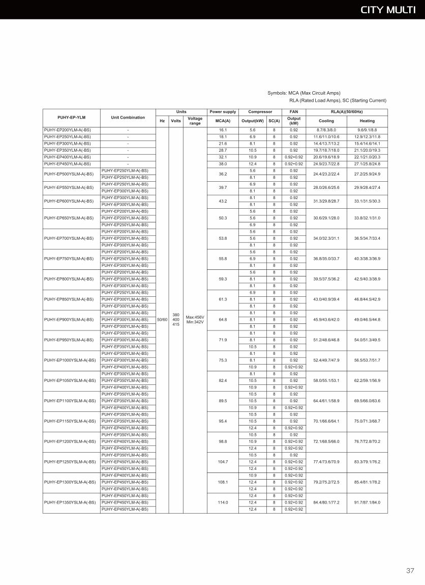
37
4 - 10
S.D
. Y
MEE14K009
1. Electrical work AN1 2nd
Symbols: MCA (Max Circuit Amps)RLA (Rated Load Amps), SC (Starting Current)
PUHY-EP-YLM Unit CombinationUnits Power supply Compressor FAN RLA(A)(50/60Hz)
Hz Volts Voltage range MCA(A) Output(kW) SC(A) Output
(kW) Cooling Heating
PUHY-EP200YLM-A(-BS) -
50/60380 400 415
Max:456V Min:342V
16.1 5.6 8 0.92 8.7/8.3/8.0 9.6/9.1/8.8
PUHY-EP250YLM-A(-BS) - 18.1 6.9 8 0.92 11.6/11.0/10.6 12.9/12.3/11.8
PUHY-EP300YLM-A(-BS) - 21.6 8.1 8 0.92 14.4/13.7/13.2 15.4/14.6/14.1PUHY-EP350YLM-A(-BS) - 28.7 10.5 8 0.92 19.7/18.7/18.0 21.1/20.0/19.3
PUHY-EP400YLM-A(-BS) - 32.1 10.9 8 0.92+0.92 20.6/19.6/18.9 22.1/21.0/20.3
PUHY-EP450YLM-A(-BS) - 38.0 12.4 8 0.92+0.92 24.9/23.7/22.8 27.1/25.8/24.8
PUHY-EP500YSLM-A(-BS)PUHY-EP250YLM-A(-BS)
36.25.6 8 0.92
24.4/23.2/22.4 27.2/25.9/24.9PUHY-EP250YLM-A(-BS) 8.1 8 0.92
PUHY-EP550YSLM-A(-BS)PUHY-EP250YLM-A(-BS)
39.76.9 8 0.92
28.0/26.6/25.6 29.9/28.4/27.4PUHY-EP300YLM-A(-BS) 8.1 8 0.92
PUHY-EP600YSLM-A(-BS)PUHY-EP300YLM-A(-BS)
43.28.1 8 0.92
31.3/29.8/28.7 33.1/31.5/30.3PUHY-EP300YLM-A(-BS) 8.1 8 0.92
PUHY-EP650YSLM-A(-BS)PUHY-EP200YLM-A(-BS)
50.35.6 8 0.92
30.6/29.1/28.0 33.8/32.1/31.0PUHY-EP200YLM-A(-BS) 5.6 8 0.92
PUHY-EP250YLM-A(-BS) 6.9 8 0.92
PUHY-EP700YSLM-A(-BS)PUHY-EP200YLM-A(-BS)
53.85.6 8 0.92
34.0/32.3/31.1 36.5/34.7/33.4PUHY-EP200YLM-A(-BS) 5.6 8 0.92
PUHY-EP300YLM-A(-BS) 8.1 8 0.92
PUHY-EP750YSLM-A(-BS)PUHY-EP200YLM-A(-BS)
55.85.6 8 0.92
36.8/35.0/33.7 40.3/38.3/36.9PUHY-EP250YLM-A(-BS) 6.9 8 0.92
PUHY-EP300YLM-A(-BS) 8.1 8 0.92
PUHY-EP800YSLM-A(-BS)PUHY-EP200YLM-A(-BS)
59.35.6 8 0.92
39.5/37.5/36.2 42.5/40.3/38.9PUHY-EP300YLM-A(-BS) 8.1 8 0.92
PUHY-EP300YLM-A(-BS) 8.1 8 0.92
PUHY-EP850YSLM-A(-BS)PUHY-EP250YLM-A(-BS)
61.36.9 8 0.92
43.0/40.9/39.4 46.8/44.5/42.9PUHY-EP300YLM-A(-BS) 8.1 8 0.92
PUHY-EP300YLM-A(-BS) 8.1 8 0.92
PUHY-EP900YSLM-A(-BS)PUHY-EP300YLM-A(-BS)
64.88.1 8 0.92
45.9/43.6/42.0 49.0/46.5/44.8PUHY-EP300YLM-A(-BS) 8.1 8 0.92
PUHY-EP300YLM-A(-BS) 8.1 8 0.92
PUHY-EP950YSLM-A(-BS)PUHY-EP300YLM-A(-BS)
71.98.1 8 0.92
51.2/48.6/46.8 54.0/51.3/49.5PUHY-EP300YLM-A(-BS) 8.1 8 0.92
PUHY-EP350YLM-A(-BS) 10.5 8 0.92
PUHY-EP1000YSLM-A(-BS)PUHY-EP300YLM-A(-BS)
75.38.1 8 0.92
52.4/49.7/47.9 56.5/53.7/51.7PUHY-EP300YLM-A(-BS) 8.1 8 0.92
PUHY-EP400YLM-A(-BS) 10.9 8 0.92+0.92
PUHY-EP1050YSLM-A(-BS)PUHY-EP300YLM-A(-BS)
82.48.1 8 0.92
58.0/55.1/53.1 62.2/59.1/56.9PUHY-EP350YLM-A(-BS) 10.5 8 0.92
PUHY-EP400YLM-A(-BS) 10.9 8 0.92+0.92
PUHY-EP1100YSLM-A(-BS)PUHY-EP350YLM-A(-BS)
89.510.5 8 0.92
64.4/61.1/58.9 69.5/66.0/63.6PUHY-EP350YLM-A(-BS) 10.5 8 0.92
PUHY-EP400YLM-A(-BS) 10.9 8 0.92+0.92
PUHY-EP1150YSLM-A(-BS)PUHY-EP350YLM-A(-BS)
95.410.5 8 0.92
70.1/66.6/64.1 75.0/71.3/68.7PUHY-EP350YLM-A(-BS) 10.5 8 0.92
PUHY-EP450YLM-A(-BS) 12.4 8 0.92+0.92
PUHY-EP1200YSLM-A(-BS)PUHY-EP350YLM-A(-BS)
98.810.5 8 0.92
72.1/68.5/66.0 76.7/72.8/70.2PUHY-EP400YLM-A(-BS) 10.9 8 0.92+0.92
PUHY-EP450YLM-A(-BS) 12.4 8 0.92+0.92
PUHY-EP1250YSLM-A(-BS)PUHY-EP350YLM-A(-BS)
104.710.5 8 0.92
77.4/73.6/70.9 83.3/79.1/76.2PUHY-EP450YLM-A(-BS) 12.4 8 0.92+0.92
PUHY-EP450YLM-A(-BS) 12.4 8 0.92+0.92
PUHY-EP1300YSLM-A(-BS)PUHY-EP400YLM-A(-BS)
108.110.9 8 0.92+0.92
79.2/75.2/72.5 85.4/81.1/78.2PUHY-EP450YLM-A(-BS) 12.4 8 0.92+0.92
PUHY-EP450YLM-A(-BS) 12.4 8 0.92+0.92
PUHY-EP1350YSLM-A(-BS)PUHY-EP450YLM-A(-BS)
114.012.4 8 0.92+0.92
84.4/80.1/77.2 91.7/87.1/84.0PUHY-EP450YLM-A(-BS) 12.4 8 0.92+0.92
PUHY-EP450YLM-A(-BS) 12.4 8 0.92+0.92
0000003416.BOOK 10 ページ 2014年11月11日 火曜日 午前9時34分

38
4 - 71
1. Electrical work AN1 2nd
S.D. R
2
MEE14K009
1-2-2. Electrical characteristics of Outdoor unit at cooling modeSymbols: MCA (Max Circuit Amps)
RLA (Rated Load Amps), SC (Starting Current)
PURY-P-YLM Unit CombinationUnits Power
supply Compressor FAN RLA(A)(50/60Hz)
Hz Volts Voltage range MCA(A) Output
(kW) SC(A) Output(kW) Cooling Heating
PURY-P200YLM-A(-BS) -
50/60380400415
Max:456VMin:342V
16.1 5.6 8 0.92 10.0/9.5/9.1 11.0/10.4/10.1PURY-P250YLM-A(-BS) - 20.5 6.9 8 0.92 13.3/12.7/12.2 14.6/13.8/13.3PURY-P300YLM-A(-BS) - 25.4 8.1 8 0.92 16.5/15.7/15.1 18.1/17.2/16.6PURY-P350YLM-A(-BS) - 30.6 10.5 8 0.92 21.4/20.3/19.6 21.8/20.8/20.0
PURY-P400YSLM-A(-BS)PURY-P200YLM-A(-BS)
30.85.6 8 0.92
20.8/19.8/19.1 22.0/20.9/20.2PURY-P200YLM-A(-BS) 5.6 8 0.92
PURY-P450YSLM-A(-BS)PURY-P250YLM-A(-BS)
35.56.9 8 0.92
23.9/22.7/21.8 25.3/24.0/23.2PURY-P200YLM-A(-BS) 5.6 8 0.92
PURY-P500YSLM-A(-BS)PURY-P250YLM-A(-BS)
40.96.9 8 0.92
27.6/26.2/25.3 29.2/27.7/26.7PURY-P250YLM-A(-BS) 6.9 8 0.92
PURY-P550YSLM-A(-BS)PURY-P300YLM-A(-BS)
45.88.1 8 0.92
31.6/30.0/28.9 32.7/31.0/29.9PURY-P250YLM-A(-BS) 6.9 8 0.92
PURY-P600YSLM-A(-BS)PURY-P300YLM-A(-BS)
52.08.1 8 0.92
35.2/33.5/32.3 37.1/35.2/33.9PURY-P300YLM-A(-BS) 8.1 8 0.92
PURY-P650YSLM-A(-BS)PURY-P350YLM-A(-BS)
55.510.5 8 0.92
38.7/36.8/35.4 39.6/37.6/36.2PURY-P300YLM-A(-BS) 8.1 8 0.92
PURY-P700YSLM-A(-BS)PURY-P350YLM-A(-BS)
61.910.5 8 0.92
44.2/42.0/40.5 42.9/40.7/39.3PURY-P350YLM-A(-BS) 10.5 8 0.92
PURY-P750YSLM-A(-BS)PURY-P400YLM-A(-BS)
66.710.9 8 0.92
47.6/45.2/43.6 43.0/40.8/39.4PURY-P350YLM-A(-BS) 10.5 8 0.92
PURY-P800YSLM-A(-BS)PURY-P400YLM-A(-BS)
71.610.9 8 0.92
51.1/48.5/46.8 42.0/39.9/38.5PURY-P400YLM-A(-BS) 10.9 8 0.92
PURY-P850YSLM-A(-BS)PURY-P450YLM-A(-BS)
73.712.4 8 0.92
52.6/49.9/48.1 48.1/45.7/44.1PURY-P400YLM-A(-BS) 10.9 8 0.92
PURY-P900YSLM-A(-BS)PURY-P450YLM-A(-BS)
76.812.4 8 0.92
53.2/50.6/48.7 54.8/52.0/50.1PURY-P450YLM-A(-BS) 12.4 8 0.92
PURY-EP-YLM Unit CombinationUnits Power
supply Compressor FAN RLA(A)(50/60Hz)
Hz Volts Voltage range MCA(A) Output
(kW) SC(A) Output(kW) Cooling Heating
PURY-EP200YLM-A(-BS) -
50/60380400415
Max:456VMin:342V
16.1 5.6 8 0.92 9.2/8.7/8.4 10.8/10.2/9.9PURY-EP250YLM-A(-BS) - 19.9 6.9 8 0.92 12.2/11.6/11.2 14.2/13.5/13.0PURY-EP300YLM-A(-BS) - 23.6 8.1 8 0.92 15.5/14.7/14.2 16.8/15.9/15.4PURY-EP350YLM-A(-BS) - 30.6 10.5 8 0.92 21.2/20.1/19.4 21.8/20.7/19.9PURY-EP400YLM-A(-BS) - 31.7 10.9 8 0.92 21.2/20.1/19.4 22.6/21.4/20.7PURY-EP450YLM-A(-BS) - 37.4 12.4 8 0.92 25.0/23.7/22.9 26.7/25.4/24.5
PURY-EP500YSLM-A(-BS)PURY-EP250YLM-A(-BS)
39.96.9 8 0.92
25.2/24.0/23.1 28.5/27.1/26.1PURY-EP250YLM-A(-BS) 6.9 8 0.92
PURY-EP550YSLM-A(-BS)PURY-EP300YLM-A(-BS)
43.68.1 8 0.92
29.2/27.8/26.8 31.1/29.5/28.5PURY-EP250YLM-A(-BS) 6.9 8 0.92
PURY-EP600YSLM-A(-BS)PURY-EP300YLM-A(-BS)
48.18.1 8 0.92
32.9/31.3/30.2 34.3/32.6/31.4PURY-EP300YLM-A(-BS) 8.1 8 0.92
PURY-EP650YSLM-A(-BS)PURY-EP350YLM-A(-BS)
53.210.5 8 0.92
37.3/35.4/34.1 38.0/36.1/34.7PURY-EP300YLM-A(-BS) 8.1 8 0.92
PURY-EP700YSLM-A(-BS)PURY-EP350YLM-A(-BS)
59.810.5 8 0.92
43.8/41.6/40.1 42.6/40.5/39.0PURY-EP350YLM-A(-BS) 10.5 8 0.92
PURY-EP750YSLM-A(-BS)PURY-EP400YLM-A(-BS)
62.310.9 8 0.92
43.8/41.6/40.1 44.5/42.3/40.7PURY-EP350YLM-A(-BS) 10.5 8 0.92
PURY-EP800YSLM-A(-BS)PURY-EP400YLM-A(-BS)
63.310.9 8 0.92
43.7/41.5/40.0 45.2/42.9/41.4PURY-EP400YLM-A(-BS) 10.9 8 0.92
PURY-EP850YSLM-A(-BS)PURY-EP450YLM-A(-BS)
70.312.4 8 0.92
48.0/45.6/44.0 50.2/47.7/45.9PURY-EP400YLM-A(-BS) 10.9 8 0.92
PURY-EP900YSLM-A(-BS)PURY-EP450YLM-A(-BS)
75.612.4 8 0.92
52.2/49.6/47.8 54.0/51.3/49.4PURY-EP450YLM-A(-BS) 12.4 8 0.92
0000003417.BOOK 71 ページ 2014年10月22日 水曜日 午前10時35分
Power supply for indoor and outdoor units (CONTINUED)

39
1. Electrical work AN1 2nd
4 - 72
S.D
. R2
MEE14K009
1-2-3. Electrical characteristics of BC controllerSymbols: MCA (Max. Circuit Amps), MFA (Max. Fuse Amps), RLA (Rated Load Amps)
BC controllerPower supply
RLA(A)Hz Volts Range+-10% MCA(A) MFA(A)
CMB-P104V-G1
50/60
220
Max.: 264VMin.: 198V
0.45
15
0.31230 0.34240 0.36
CMB-P105V-G1220
0.550.38
230 0.41240 0.44
CMB-P106V-G1220
0.650.45
230 0.48240 0.52
CMB-P108V-G1220
0.850.58
230 0.63240 0.68
CMB-P1010V-G1220
1.040.71
230 0.77240 0.83
CMB-P1013V-G1220
1.340.92
230 1.00240 1.07
CMB-P1016V-G1220
1.631.12
230 1.22240 1.30
CMB-P108V-GA1220
0.850.58
230 0.63240 0.68
CMB-P1010V-GA1220
1.040.71
230 0.77240 0.83
CMB-P1013V-GA1220
1.340.92
230 1.00240 1.07
CMB-P1016V-GA1220
1.631.12
230 1.22240 1.30
CMB-P1016V-HA1220
1.631.12
230 1.22240 1.30
CMB-P104V-GB1220
0.400.28
230 0.30240 0.32
CMB-P108V-GB1220
0.790.55
230 0.59240 0.63
CMB-P1016V-HB1220
1.581.08
230 1.17240 1.26
0000003417.BOOK 72 ページ 2014年10月22日 水曜日 午前10時35分
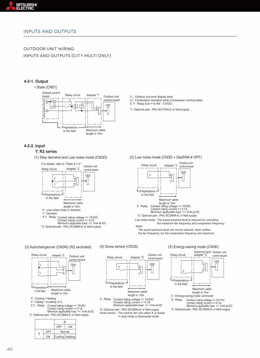
40
INPUTS AND OUTPUTS
OUTDOOR UNIT WIRING
INPUTS AND OUTPUTS (CITY MULTI ONLY)
3 - 108
Con
trol
ler
MEE14K009
4. System component AN1 2nd
4-2. Outdoor unit input/output connector
CN51
XY
L1
L2
Lamp
powe
r sou
rce
Distant control board Relay circuit Adapter *1 Outdoor unit
control board
Preparationsin the field
L1 : Outdoor unit error display lampL2 : Compressor operation lamp (compressor running state)X, Y : Relay (coil =<0.9W : 12VDC)
Maximum cable length is 10m
• State (CN51)4-2-1. Output
(1) Step demand and Low noise mode (CN3D)
4-2-2. InputY, R2 series
543
*2. Optional part : PAC-SC36NA-E or field supply.
For details, refer to "Table 4-1-2."
*2. Optional part : PAC-SC36NA-E or field supply.
*2. Optional part : PAC-SC36NA-E or field supply.
*2. Optional part : PAC-SC36NA-E or field supply.
(4) Snow sensor (CN3S)
X : Low noise mode or demandY : DemandX,Y : Relay
X : Relay
Snow sensor : The outdoor fan runs when X is closed in stop mode or thermostat mode.
XCN3S
Preparationsin the fieldPreparations
in the field Maximum cable length is 10m
Adapter *2Outdoor unitcontrol board
2
3
1
X Y
OFF
Cooling
ON
Heating
NormalY OFF
ON
X
Contact rating voltage >= 15VDCContact rating current >= 0.1AMinimum appicable load =< 1mA at DC
Contact rating voltage >= 15VDCContact rating current >= 0.1AMinimum applicable load =< 1mA at DC
Contact rating voltage >= 15VDCContact rating current >= 0.1AMinimum applicable load =< 1mA at DC
(2) Low noise mode (CN3D + DipSW4-4 OFF)
XCN3D
Preparationsin the field
Maximum cable length is 10m
Adapter *2Outdoor unitcontrol board
2
3
1
X : Relay
: The sound pressure level is reduced by controlling the maximum fan frequency and compressor frequency.
-Note- The sound pressure level can not be reduced, when neither the fan frequency nor the compressor frequency are maximum.
Contact rating voltage >= 15VDCContact rating current >= 0.1AMinimum applicable load =< 1mA at DC
Low noise mode
Relay circuit
Y
XCN3D
Preparationsin the field
Maximum cable length is 10m
Adapter *2Outdoor unitcontrol board
3
21
(3) Autochangeover (CN3N) (R2 excluded)
X : Cooling / HeatingY : Validity / Invalidity of XX,Y : Relay
CN3NX
Y
Relay circuit
Relay circuit
Relay circuitAdapter *2 Outdoor unit
control board
Maximum cable length is 10m
12
3
*1. Optional part : PAC-SC37SA-E or field supply.
Caution:3.The electric strength between accessible parts and control circuit should have 2750V or more.
1.Wiring should be covered by insulation tube with supplementary insulation.2.Use relays or switches with IEC or equivalent standard.
(5) Energy-saving mode (CN3K)
*2. Optional part : PAC-SC36NA-E or field supply.
X : Energy-saving mode commandX : Relay Contact rating voltage >= DC15V
Contact rating current >= 0.1AMinimum appicable load =< 1mA at DC
X
CN3K
Preparationsin the field
Maximum cable length is 10m
Outdoor unitcontrol board
321
Relay circuitExternal input adapter *2
0000003415.BOOK 108 ページ 2014年10月15日 水曜日 午前9時4分

41
S SERIES OUTDOOR UNIT WIRING
INPUTS AND OUTPUTS (CITY MULTI ONLY)

42
INDOOR UNIT WIRING
INPUTS AND OUTPUTS (CITY MULTI ONLY)
INPUTS AND OUTPUTS (Continued)

43
Installation of the M-Net is an essential part of any City Multi installation. The wiring itself is simple but there are a number of
basic rules that must be followed to avoid communication problems within the system.
ALWAYS FOLLOW THE PIPING AND WIRING SCHEMATICS
• There are two separate M-Net control daisy chains in most City Multi installations:
1. The first M-Net starts from TB3 on the first outdoor unit, it is 24-30VDC and daisy chains between outdoor units, branch controller and indoor units within that system. Star point connections are not acceptable except when wiring in a sub BC and must have only one star point connection leading to the sub BC (as shown on the piping and wiring schematic).
2. The second M-Net starts from TB7 on the first outdoor unit, it is 22-28VDC and daisy chains from system/central controllers and all other outdoor units on all systems that are connected to the central controller. Star point connections are not acceptable.
• Each M-Net shield must be earthed in one place only. Multiple earths can cause the shield to act like an aerial, causing communication problems.
• M-Net wiring must be kept separate from other wiring to avoid induced noise.
M-Net Wiring
RECOMMENDED M-NET WIRING PROCEDURE
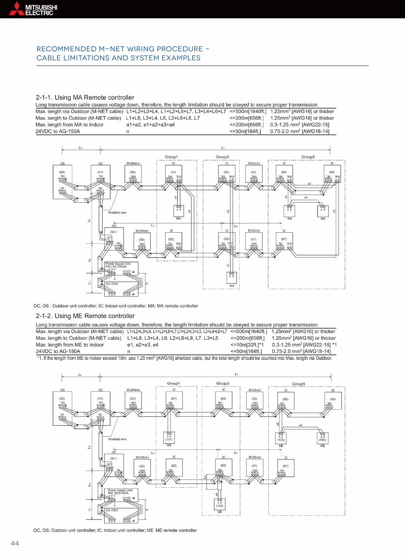
44
RECOMMENDED M-NET WIRING PROCEDURE – CABLE LIMITATIONS AND SYSTEM EXAMPLES

45
Vector Office Building - Auckland
1. Follow all pertinent wiring regulations and safety procedures.
2. Transmission control cables where possible must be 50mm away from mains cable to prevent electrical noise affecting the control circuit. Do not run control and mains in the same conduit.
3. Earth and neutral connection and testing back to MCC must be carried out by an electrician prior to powering up the outdoor unit.
4. Do not connect 230 volts to M-Net connection. This will result in catastrophic board failure.
5. Two core screened 1.25mm2 cables must be used for all M-Net wiring. Failure to do so will void all warranty and cause control system errors.
Royal Thai Embassy, Wellington
RECOMMENDED M-NET WIRING PROCEDURE – CABLE LIMITATIONS AND SYSTEM EXAMPLES

46
All City Multi equipment that sits on the M-Net requires a numerical address. This address allows
the system to identify, control, log and allocate faults to an individual piece of equipment.
Addressing must be completed at the time of installation prior to commissioning.
The address setting is generally carried out by the installation electrician as the addressing rotary
switches are located in or close to the electrical terminal boxes.
The piping installer must clearly identify and label each item of plant with permanent marker or
other labelling system with the following:
• Address
• Indoor/Outdoor/BC Name
• Port Number (R2 equipment only)
ADDRESSING MUST FOLLOW THE PIPING AND WIRING SCHEMATICS.
Rotary Switch Operation
Addresses are set using numerical rotary switches. There are two rotary tumblers for address setting
- the 10’s and the 1’s. For R2 indoor units a port setting is required. This tumbler can be set from 1
to 16. For this tumbler, A=10, B=11, C=12, D=13, E=14, F=15 and 0=16.
NOTE: Be sure power is off before setting address settings.
Ensure no two addresses are the same as this will cause a fault and the system will not operate.
Rotary Switches
M-NET ADDRESSING
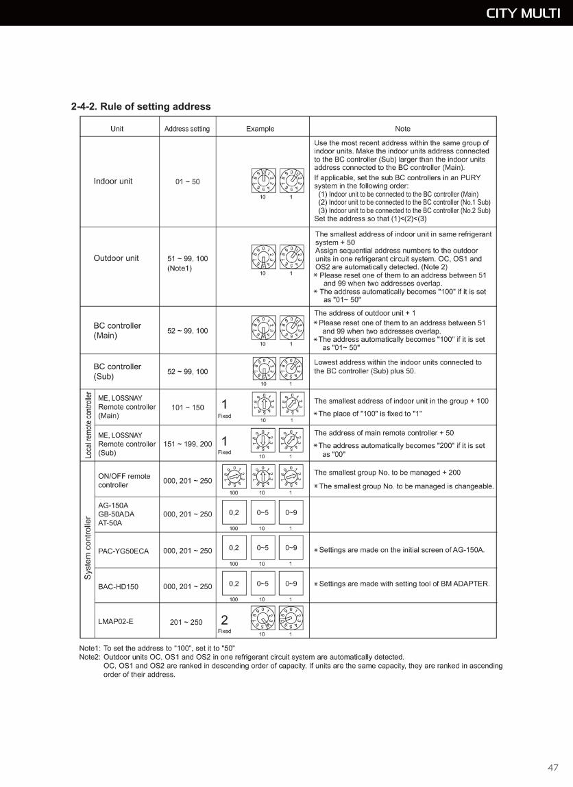
47

48
BASIC SYSTEM, M-NET WIRING AND ADDRESSING EXAMPLE:
M-NET ADDRESSING (Continued)

49
PIPING AND WIRING SCHEMATICS
Piping and wiring schematics are essential to any new installation. The installer must have these on site
during the installation and follow them closely.
The schematics identify:
• Project name
• BDT quote number
• Equipment model numbers
• Group names
• Piping layout and sizes
• Wiring layout
• M-Net addresses
An A3 piping and wiring schematic for this project is located in the sleeve at the back of this booklet.
If the installation varies from this schematic in any way it should be identified on the schematic and
returned to BDT to re-write into an as-built schematic of the system on completion of installation.
A copy of the as-built piping and wiring schematics should be left on site as a reference for fault finding,
maintenance or servicing of the equipment if required in the future.
Branch Controller Piping
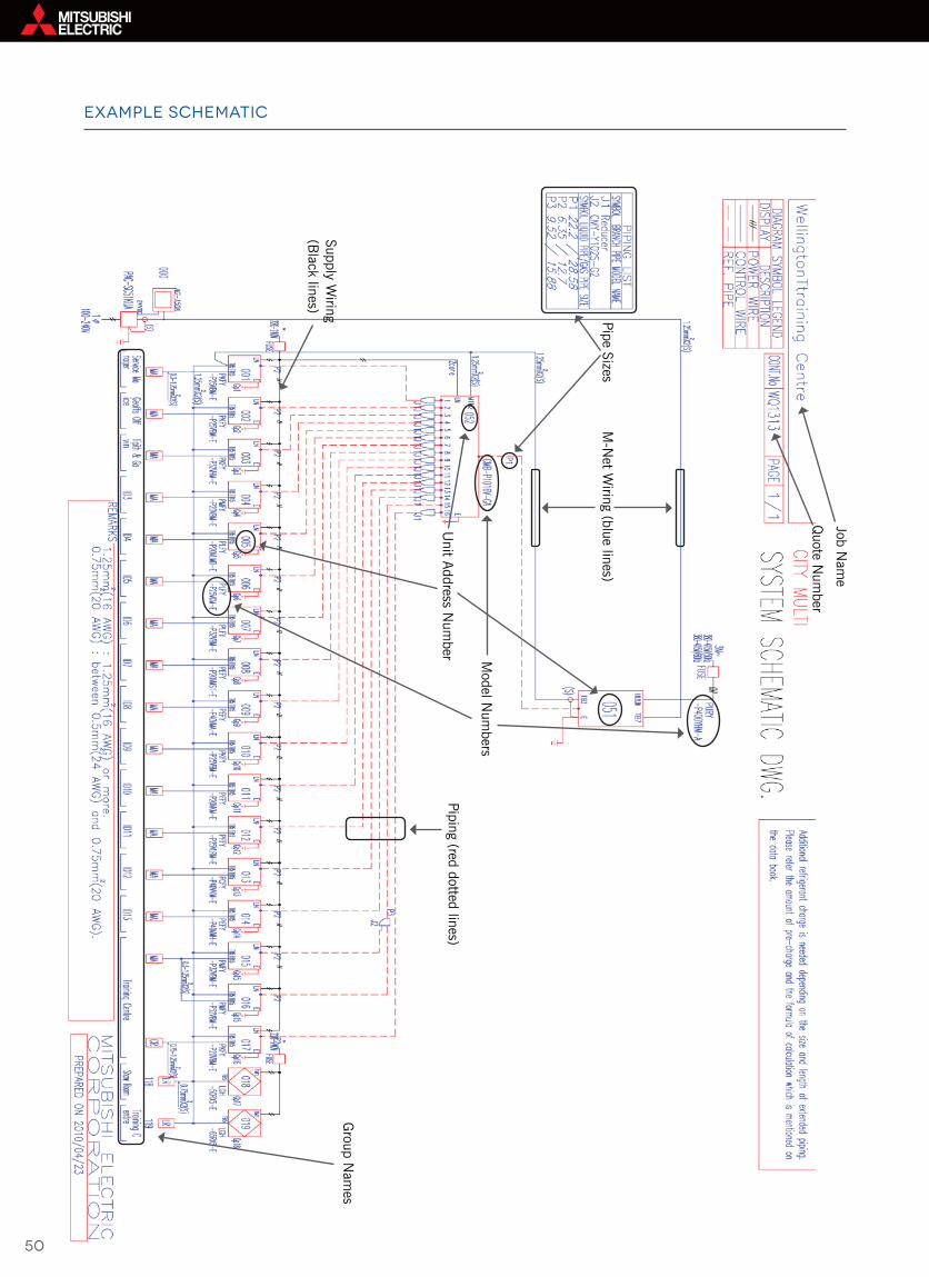
50
Job Nam
e
Quote N
umber
M-N
et Wiring (blue lines)
Pipe Sizes
Unit A
ddress Num
berPiping (red dotted lines)
Model N
umbers
Group N
ames
Supply Wiring
(Black lines)
EXAMPLE SCHEMATIC
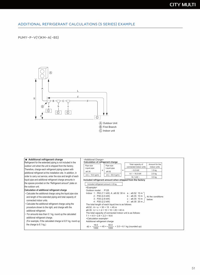
51
ADDITIONAL REFRIGERANT CALCULATIONS (S SERIES) example
127
10 REFRIGERANT PIPING TASKS
Line-Branch MethodConnection Examples(Connecting to 4 Indoor Units)
Liquid Line
Gas Line
Piping Diameter (mm)Model
Liquid Line (mm) Gas Line (mm){15.88{9.52
Liquid LineGas Line
Liquid LineGas Line
Piping Diameter (mm)Model number
50 or lower
63 to 140
{6.35{12.7{9.52{15.88
Outdoor UnitFirst BranchIndoor unit
ABC
A+B+C+a+b+c+d [ 300 mA+B+C+d [ 150 m B+C+d [ 30 m50 meters or less (If the outdoor unit is lower, 40 meters or less)15 meters or lessUse an optional branch piping kit (CMY-Y62-G-E).
Total Piping LengthFarthest Piping LengthFarthest Piping Length After First BranchHigh/Low Difference in Indoor/Outdoor SectionHigh/Low Difference in Indoor/Indoor Section
PermissibleLength
Permissible High/Low Difference
(L)(R)(H)(h)
■ Selecting the Refrigerant Branch Kit■ Select Each Section of Refrigerant Piping
■ Additional refrigerant charge
Select the size from the table to the right.
(1) Refrigerant Piping Diameter In Section From Outdoor Unit to First Branch (Outdoor Unit Piping Diameter)(1) Section From Outdoor Unit
to First Branch (A)(2) Sections From Branch to Indoor Unit (a,b,c,d)(3) Section From Branch to Branch (B,C)
(3) Refrigerant Piping Diameter In Section From Branch to Branch
(2) Refrigerant Piping Diameter In Section From Branch to Indoor Unit (Indoor Unit Piping Diameter)
EachSection ofPiping
Refrigerant for the extended piping is not included in the outdoor unit when the unit is shipped from the factory. Therefore, charge each refrigerant piping system with additional refrigerant at the installation site. In addition, in order to carry out service, enter the size and length of each liquid pipe and additional refrigerant charge amounts inthe spaces provided on the “Refrigerant amount” plate on the outdoor unit.Calculation of additional refrigerant charge• Calculate the additional charge using the liquid pipe size
and length of the extended piping and total capacity of connected indoor units.
• Calculate the additional refrigerant charge using the procedure shown to the right, and charge with the additional refrigerant.
• For amounts less than 0.1 kg, round up the calculated additional refrigerant charge.(For example, if the calculated charge is 6.01 kg, round upthe charge to 6.1 kg.)
{9.52
{15.88
PUMY-P112PUMY-P125PUMY-P140
<Additional Charge>Calculation of refrigerant charge
Pipe sizeLiquid pipe
+
Pipe sizeLiquid pipe
+
Total capacity of connected indoor units
Amount for the indoor units
ø6.35 ø9.52~ 8.0 kW 1.5 kg
(m) × 19.0 (g/m) (m) × 50.0 (g/m)8.1 ~ 16.0 kW 2.5 kg
16.1 kW ~ 3.0 kgIncluded refrigerant amount when shipped from the factory
Included refrigerant amount: 4.8 kg
40 ×19.0
+ 45 ×50.0
+ 3.0 = 6.1 kg (rounded up)1000 1000
<Example>Outdoor model : P125Indoor 1 : P63 (7.1 kW) A : ø9.52 30 m a : ø9.52 15 m 2 : P40 (4.5 kW) b : ø6.35 10 m 3 : P25 (2.8 kW) c : ø6.35 10 m 4 : P20 (2.2 kW) d : ø6.35 20 mThe total length of each liquid line is as follows:ø9.52 : A + a = 30 + 15 = 45 mø6.35 : b + c + d = 10 + 10 + 20 = 40 mThe total capacity of connected indoor unit is as follows:7.1 + 4.5 + 2.8 + 2.2 = 16.6<Calculation example>Additional refrigerant charge
At the conditions below:
B
A
A
H
B C
L
R
d
a
h
b c
C
C
C C
Note: When connecting the CONNECTION KIT (PAC-LV11M-J) and an M-series indoorunit, refer to the installation manual for the CONNECTION KIT when selecting thepipe size and piping length.
10-1. REFRIGERANT PIPING SYSTEM
OCH549
PUMY-P-V(Y)KM-A(-BS)

52
ADDITIONAL REFRIGERANT CALCULATIONS (Y SERIES) example
4 - 44
S.D
. Y
MEE14K009
3. Piping Design AN1 2nd
3-3. Refrigerant charging calculation
(1) Calculation of additional refrigerant charge Calculate the amount of additional charge based on the length of the piping extension and the size of the refrigerant line. Use the table to the below as a guide to calculating the amount of additional charging and charge the system accordingly. If the calculation results in a fraction of less than 0.1kg, round up to the next 0.1kg. For example, if the result of the calculation was 12.33kg, round the result up to 12.4kg.
At the time of shipping, the outdoor unit is charged with the refrigerant. As this charge does not include the amount needed for extendedpiping, additional charging for each refrigerant line will be required on site. In order that future servicing may be properly provided, always keep a record of the size and length of each refrigerant line and the amount of additional charge by writing it in the space provided on the outdoor unit.
<Additional Charge>
PUHY-P-YKB
Units "m" and "kg"
<Formula>When the piping length from the outdoor unit to the farthest indoor unit is 30.5 m (100 ft) or shorter
Amount of additional charge (kg)
= ø19.05 total length × 0.29 (kg/m) + ø15.88 total length
× 0.2 (kg/m) + ø12.7 total length × 0.12 (kg/m) + ø9.52 total length
× 0.06 (kg/m) + ø6.35 total length × 0.024 (kg/m)
+
Outdoor unit model Amount (kg)
+
Total capacity of connected indoor units Amount (kg)
P200 0 80 or below 2.0P250 0 81 to 160 2.5P300 0 161 to 330 3.0P350 0
00
331 to 390 3.5P400 391 to 480 4.5P450 481 to 630 5.0
631 to 710 6.0711 to 800 8.0801 to 890 9.0891 to 1070 10.01071 to 1250 12.0
1251 or above 14.0
When the piping length from the outdoor unit to the farthest indoor unit is longer than 30.5 m (100 ft)
Amount of additional charge (kg)
= ø19.05 total length × 0.26 (kg/m) + ø15.88 total length
× 0.18 (kg/m) + ø12.7 total length × 0.11 (kg/m) + ø9.52 total length
× 0.054 (kg/m) + ø6.35 total length × 0.021 (kg/m)
+
Outdoor unit model Amount (kg)
+
Total capacity of connected indoor units Amount (kg)
P200 0 80 or below 2.0P250 0 81 to 160 2.5P300 0 161 to 330 3.0P350 0
00
331 to 390 3.5P400 391 to 480 4.5P450 481 to 630 5.0
631 to 710 6.0711 to 800 8.0801 to 890 9.0891 to 1070 10.01071 to 1250 12.0
1251 or above 14.0
0000003416.BOOK 44 ページ 2014年11月11日 火曜日 午前9時34分
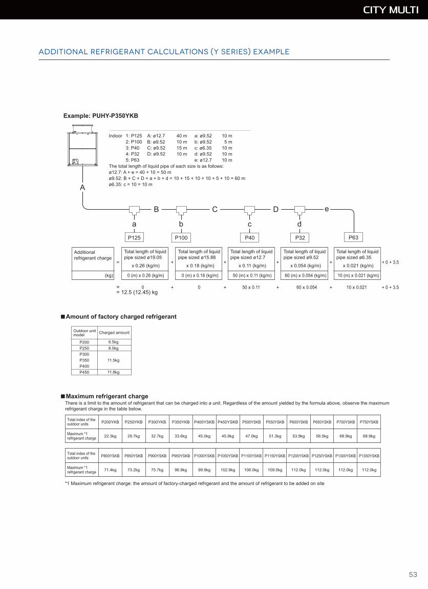
53
ADDITIONAL REFRIGERANT CALCULATIONS (Y SERIES) example
4 - 45
S.D. Y
MEE14K009
3. Piping Design AN1 2nd
A
B C D e
a b c d
Indoor 1: P125 40 m 10 m2: P100 10 m 5 m3: P40 15 m 10 m4: P32 10 m 10 m5: P63 10 m
The total length of liquid pipe of each size is as follows:ø12.7: A + e = 40 + 10 = 50 m
A: ø12.7 a: ø9.52b: ø9.52c: ø6.35d: ø9.52e: ø12.7
B: ø9.52C: ø9.52D: ø9.52
ø9.52: B + C + D + a + b + d = 10 + 15 + 10 + 10 + 5 + 10 = 60 mø6.35: c = 10 = 10 m
Example: PUHY-P350YKB
P40P100P125 P32 P63
= + + + + + 3.5
+ + + + + 3.5
+ 0
+ 0
(kg) 0 (m) x 0.26 (kg/m)
Additional refrigerant charge
= 0 0 50 x 0.11 60 x 0.054 10 x 0.021= 12.5 (12.45) kg
Total length of liquid
x 0.26 (kg/m)
0 (m) x 0.18 (kg/m)
Total length of liquid
x 0.18 (kg/m)
50 (m) x 0.11 (kg/m)
Total length of liquid
x 0.11 (kg/m)
60 (m) x 0.054 (kg/m)
Total length of liquid
x 0.054 (kg/m)
10 (m) x 0.021 (kg/m)
Total length of liquid
x 0.021 (kg/m)
Maximum refrigerant charge
Amount of factory charged refrigerant
There is a limit to the amount of refrigerant that can be charged into a unit. Regardless of the amount yielded by the formula above, observe the maximumrefrigerant charge in the table below.
Total index of theoutdoor units P200YKB
22.3kg
P250YKB
29.7kg
P300YKB
32.7kg
P350YKB
33.6kg
P400YSKB
45.0kg
P450YSKB
45.9kg
P500YSKB
47.0kg
P550YSKB
51.3kg
P600YSKB
53.9kg
P650YSKB
56.5kg
P750YSKB
68.9kgMaximum *1 refrigerant charge
*1 Maximum refrigerant charge: the amount of factory-charged refrigerant and the amount of refrigerant to be added on site
P700YSKB
68.9kg
Total index of theoutdoor units P800YSKB
71.4kg
P850YSKB
73.2kg
P900YSKB
75.7kg
P950YSKB
96.9kg
P1000YSKB
99.9kg
P1050YSKB
102.9kg
P1100YSKB
106.0kg
P1150YSKB
109.0kg
P1200YSKB
112.0kg
P1250YSKB
112.0kg
P1300YSKB
112.0kg
P1350YSKB
112.0kgMaximum *1 refrigerant charge
8.0kg6.5kg
11.5kg
11.8kg
P200P250P300P350P400P450
Outdoor unitmodel Charged amount
0000003416.BOOK 45 ページ 2014年11月11日 火曜日 午前9時34分

54
ADDITIONAL REFRIGERANT CALCULATIONS (R2 SERIES) example
4 - 105
3. Piping Design AN1 2nd
S.D. R
2
MEE14K009
3-3. Refrigerant charging calculation
Sample connection (with 3 BC controller and 6 indoor units) (PURY-P700YSLM-A)
<Amount of additional refrigerant to be charged>Calculating the amount of additional refrigerant to be charged
BC controller (Main BC)
IU
a
IU
C
b
IU1 : P50 2 : P250
Joint kit
IU
Joint BC controller (Sub BC)
BC controller (Sub BC)
Bc d
IU
f
D
E
Joint
A
IUe
FH
OU(Main unit) OU
(Sub unit)
Reducer (P15-P50) (attached with BC controller)
G
3 : P15 4 : P20
5 : P140
6 : P200Amount of additional refrigerant to be chargedRefrigerant for extended pipes (field piping) is not factory-charged to the outdoor unit. Add an appropriate amount of refrigerant for each pipes on site.Record the size of each high pressure pipe and liquid pipe, and the amout of refrigerant that was charged on the outdoor unit for future reference.
Calculating the amount of additional refrigerant to be chargedThe amount of refrigerant to be charged is calculated with the size of the on-site-installed hige pressure pipes and liquid pipes, and their length.Calculate the amount of refrigerant to be charged according to the formula below.Round up the calculation result to the nearest 0.1kg. (i.e., 16.03 kg = 16.1 kg)
Outdoor Twinning kit
PURY-P-YLM
Units "m" and "kg" (In an R2 system)<Formula>• When the piping length from the outdoor unit to the farthest indoor unit is 30.5 m (100 ft) or shorter
Amount of additional charge (kg)
=High-pressure pipe ø28.58 total length × 0.36 (kg/m)
+High-pressure pipe ø22.2 total length × 0.23 (kg/m)
+High-pressure pipe ø19.05 total length × 0.16 (kg/m)
+High-pressure pipe ø15.88 total length × 0.11 (kg/m)
+Liquid pipe ø15.88 total length × 0.2 (kg/m)
+Liquid pipe ø12.7 total length × 0.12 (kg/m)
+Liquid pipe ø9.52 total length × 0.06 (kg/m)
+Liquid pipe ø6.35 total length × 0.024 (kg/m)
+
Total capacity of outdoor units
Amount(to be added for standard or
main BC controller) +Main BC controller Amount
P200 3.0kg HA-type 2.0kgP250 4.5kgP300 4.5kg
P350–900 6.0kg
+
Number of sub BC controllers
Amount(to be added for sub
BC controller)
+
Total capacity of connected indoor units
Amount(to be added for
indoor unit)1 1.0kg 80 or below 2.0kg2 2.0kg 81 to 160 2.5kg
161 to 330 3.0kg331 to 390 3.5kg391 to 480 4.5kg481 to 630 5.0kg631 to 710 6.0kg711 to 800 8.0kg801 to 890 9.0kg891 to 1070 10.0kg1071 to 1250 12.0kg
1251 or above 14.0kg
+
Outdoor unit modelAmount
(to be added for outdoor unit)
SingleP200 to P250YLM 0kgP300 to P350YLM 0kg
Combination
P400 to P550YSLM 0kgP600 to P800YSLM 0kgP850YSLM 5.5kgP900YSLM 11.0kg
0000003417.BOOK 105 ページ 2014年10月22日 水曜日 午前10時35分
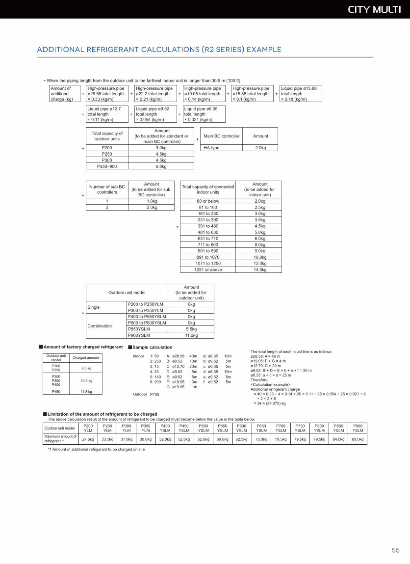
55
3. Piping Design AN1 2nd
4 - 106
S.D
. R2
MEE14K009
Amount of factory charged refrigerant
The above calculation result of the amount of refrigerant to be charged must become below the value in the table below.
*1 Amount of additional refrigerant to be charged on site
Outdoor unitModel
P250
P300
P400
P450
P350
P200
Charged amount
10.3 kg
11.8 kg
9.5 kg
Limitation of the amount of refrigerant to be charged
Sample calculation
Indoor
Outdoor
A: ø28.58 40m1: 50 a: ø6.35B: ø9.52 10m2: 250 b: ø9.52C:3: 15 c: ø6.35ø12.70 20m
4: 20 d: ø6.35D:5: 140 e: ø9.52
ø9.52 5m
6: 200
P700
The total length of each liquid line is as follows:ø28.58: A = 40 mø19.05: F + G = 4 mø12.70: C = 20 mø9.52: B + D + E + b + e + f = 35 mø6.35: a + c + d = 25 mTherefore,<Calculation example>Additional refrigerant charge = 40 × 0.33 + 4 × 0.14 + 20 × 0.11 + 35 × 0.054 + 25 × 0.021 + 6 + 2 + 2 + 6 = 34.4 (34.375) kg
f: ø9.52E: ø9.52 5mF: ø19.05 3m
10m5m5m
10m5m5m
G: ø19.05 1m
• When the piping length from the outdoor unit to the farthest indoor unit is longer than 30.5 m (100 ft)
Amount of additional charge (kg)
=High-pressure pipe ø28.58 total length × 0.33 (kg/m)
+High-pressure pipe ø22.2 total length × 0.21 (kg/m)
+High-pressure pipe ø19.05 total length × 0.14 (kg/m)
+High-pressure pipe ø15.88 total length × 0.1 (kg/m)
+Liquid pipe ø15.88 total length × 0.18 (kg/m)
+Liquid pipe ø12.7 total length × 0.11 (kg/m)
+Liquid pipe ø9.52 total length × 0.054 (kg/m)
+Liquid pipe ø6.35 total length × 0.021 (kg/m)
+
Total capacity of outdoor units
Amount(to be added for standard or
main BC controller) +Main BC controller Amount
P200 3.0kg HA-type 2.0kgP250 4.5kgP300 4.5kg
P350–900 6.0kg
+
Number of sub BC controllers
Amount(to be added for sub
BC controller)
+
Total capacity of connected indoor units
Amount(to be added for
indoor unit)1 1.0kg 80 or below 2.0kg2 2.0kg 81 to 160 2.5kg
161 to 330 3.0kg331 to 390 3.5kg391 to 480 4.5kg481 to 630 5.0kg631 to 710 6.0kg711 to 800 8.0kg801 to 890 9.0kg891 to 1070 10.0kg1071 to 1250 12.0kg
1251 or above 14.0kg
+
Outdoor unit modelAmount
(to be added for outdoor unit)
SingleP200 to P250YLM 0kgP300 to P350YLM 0kg
Combination
P400 to P550YSLM 0kgP600 to P800YSLM 0kgP850YSLM 5.5kgP900YSLM 11.0kg
Maximum amount ofrefrigerant *1
Outdoor unit model
27.5kg 33.5kg 37.0kg 39.0kg 52.0kg 59.0kg 62.5kg 75.0kg 79.5kg 84.0kg 89.0kg
P200YLM
P250YLM
P300YLM
P350YLM
P500YSLM
P550YSLM
52.0kg 52.0kg
P400YSLM
P450YSLM
P600YSLM
P650YSLM
P700YSLM
P850YSLM
P900YSLM
79.5kg 79.5kg
P750YSLM
P800YSLM
0000003417.BOOK 106 ページ 2014年10月22日 水曜日 午前10時35分
ADDITIONAL REFRIGERANT CALCULATIONS (R2 SERIES) example
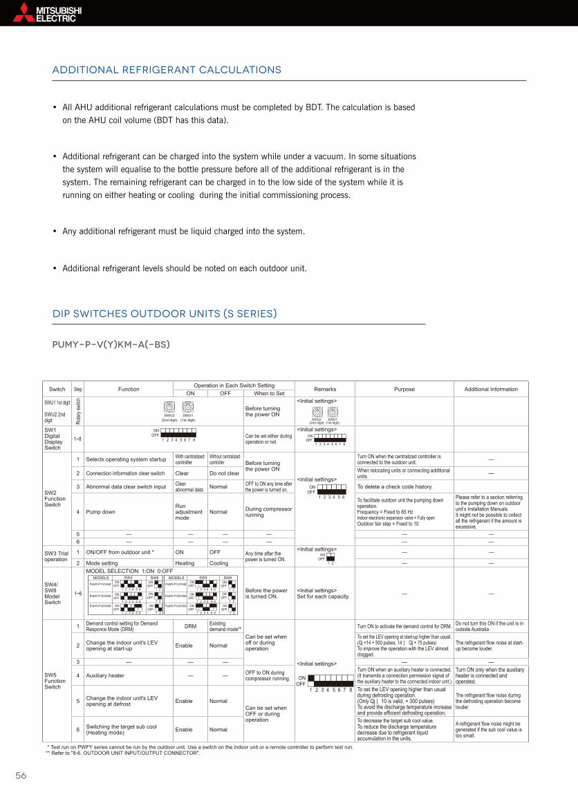
56
• All AHU additional refrigerant calculations must be completed by BDT. The calculation is based on the AHU coil volume (BDT has this data).
• Additional refrigerant can be charged into the system while under a vacuum. In some situations the system will equalise to the bottle pressure before all of the additional refrigerant is in the system. The remaining refrigerant can be charged in to the low side of the system while it is running on either heating or cooling during the initial commissioning process.
• Any additional refrigerant must be liquid charged into the system.
• Additional refrigerant levels should be noted on each outdoor unit.
DIP SWITCHES OUTDOOR UNITS (S SERIES)
104 The black square (■) indicates a sw
itch position.PU
MY-P112/125/140YK
M-A
(-BS)
Continue to the next page
8-5. INTER
NA
L SWITC
H FU
NC
TION
TAB
LEPU
MY-P112/125/140VK
M-A
(-BS)
Switch Step FunctionOperation in Each Switch Setting
Remarks Purpose Additional InformationON OFF When to Set
SWU1 1st digit
SWU2 2nd digit Ro
tary
switc
h
Before turningthe power ON
<Initial settings>
SW1 DigitalDisplaySwitch
1~8 Can be set either during operation or not.
<Initial settings>
SW2FunctionSwitch
1 Selects operating system startup With centralized controller
Without centralizedcontroller Before turning
the power ON
<Initial settings>
Turn ON when the centralized controller is connected to the outdoor unit. —
2 Connection information clear switch Clear Do not clear When relocating units or connecting additional units. —
3 Abnormal data clear switch input Clear abnormal data Normal OFF to ON any time after
the power is turned on. To delete a check code history.
4 Pump downRun adjustment mode
Normal During compressorrunning
To facilitate outdoor unit the pumping down operation.Frequency = Fixed to 65 HzIndoor-electronic expansion valve = Fully openOutdoor fan step = Fixed to 10
Please refer to a section referring to the pumping down on outdoor unit’s Installation Manuals.It might not be possible to collect all the refrigerant if the amount is excessive.
5 — — — — — —6 — — — — — —
SW3 Trialoperation
1 ON/OFF from outdoor unit * ON OFF Any time after thepower is turned ON.
<Initial settings> — —
2 Mode setting Heating Cooling — —
SW4/SW8ModelSwitch
1~6
MODEL SELECTION 1:ON 0:OFF
Before the poweris turned ON.
<Initial settings>Set for each capacity. — —
SW5FunctionSwitch
1 Demand control setting for Demand Responce Mode (DRM) DRM Existing
demand mode**Can be set when off or during operation
<Initial settings>
Turn ON to activate the demand control for DRM. Do not turn this ON if the unit is in outside Australia
2 Change the indoor unit's LEV opening at start-up Enable Normal
To set the LEV opening at start-up higher than usual.(Qj <14 + 500 pulses, 14 [ Qj + 75 pulses)To improve the operation with the LEV almost clogged.
up become louder.
3 — — — — —
4 Auxiliary heater — — OFF to ON during compressor running.
Turn ON when an auxiliary heater is connected.(It transmits a connection permission signal of the auxiliary heater to the connected indoor unit.)
Turn ON only when the auxiliary heater is connected and operated.
5 Change the indoor unit's LEV opening at defrost Enable Normal
Can be set when OFF or during operation
To set the LEV opening higher than usual during defrosting operation.(Only Qj [ 10 is valid, + 300 pulses)To avoid the discharge temperature increase
the defrosting operation become louder.
6 Switching the target sub cool(Heating mode) Enable Normal
To decrease the target sub cool value.To reduce the discharge temperature decrease due to refrigerant liquid accumulation in the units.
generated if the sub cool value is too small.
* Test run on PWFY series cannot be run by the outdoor unit. Use a switch on the indoor unit or a remote controller to perform test run. ** Refer to "8-6. OUTDOOR UNIT INPUT/OUTPUT CONNECTOR".
SWU2(2nd digit)
0 123
45678 9
SWU1(1st digit)
0 123
45678 9
1
ONOFF
2 3 4 5 6 7 8
SW4MODELS
PUMY-P112VKM
SW8
PUMY-P125VKM
PUMY-P140VKM
1
ONOFF
2 3 4 5 6
1
ONOFF
2 3 4 5 6
1
ONOFF
2 3 4 5 6
1
ONOFF
2
1
ONOFF
2
1
ONOFF
2
SW4MODELS
PUMY-P112YKM
SW8
PUMY-P125YKM
PUMY-P140YKM
1
ONOFF
2 3 4 5 6
1
ONOFF
2 3 4 5 6ON
OFF
1
ONOFF
2
1
ONOFF
2
1
ONOFF
21 2 3 4 5 6
SWU2(2nd digit)
0 123
45678 9
SWU1(1st digit)
0 123
45678 9
1
ONOFF
2 3 4 5 6 7 8
1
ONOFF
2 3 4 5 6
1
ONOFF
2
1
ONOFF
2 3 4 5 6 7 8
OCH
549
ADDITIONAL REFRIGERANT CALCULATIONS
PUMY-P-V(Y)KM-A(-BS)
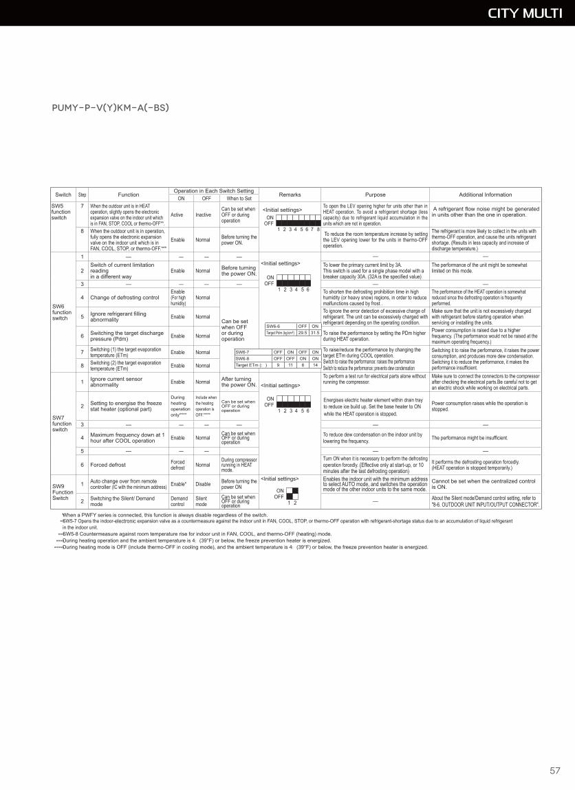
57
105
The black square (■) indicates a sw
itch position.
1
ONOFF
2 3 4 5 6 7 8
1
ONOFF
2 3 4 5 6
1
ONOFF
2
<Initial settings>
Switch Step FunctionOperation in Each Switch Setting
Remarks Purpose Additional InformationON OFF When to SetSW5functionswitch
7 When the outdoor unit is in HEAT operation, slightly opens the electronic expansion valve on the indoor unit which is in FAN, STOP, COOL or thermo-OFF**.
Active InactiveCan be set when OFF or during operation
To open the LEV opening higher for units other than in HEAT operation. To avoid a refrigerant shortage (less capacity) due to refrigerant liquid accumulation in the units which are not in operation.
A refrigerant noise might be generated in units other than the one in operation.
8 When the outdoor unit is in operation, fully opens the electronic expansion valve on the indoor unit which is in FAN, COOL, STOP, or thermo-OFF.***
Enable Normal Before turning the power ON.
To reduce the room temperature increase by setting the LEV opening lower for the units in thermo-OFF operation.
The refrigerant is more likely to collect in the units with thermo-OFF operation, and cause the units refrigerant shortage. (Results in less capacity and increase of discharge temperature.)
SW6functionswitch
1 — — — —<Initial settings>
— —
2Switch of current limitation reading in a different way
Enable Normal Before turning the power ON.
To lower the primary current limit by 3A.This switch is used for a single phase model with a
The performance of the unit might be somewhat limited on this mode.
3 — — — — — —
4 Change of defrosting controlEnable(For high humidity)
Normal
Can be set when OFF or during operation
To shorten the defrosting prohibition time in high humidity (or heavy snow) regions, in order to reduce malfunctions caused by frost .
The performance of the HEAT operation is somewhat reduced since the defrosting operation is frequently performed.
5 Ignore refrigerant abnormality Enable Normal
To ignore the error detection of excessive charge of refrigerant. The unit can be excessively charged with refrigerant depending on the operating condition.
Make sure that the unit is not excessively charged with refrigerant before starting operation when servicing or installing the units.
6 Switching the target dischargepressure (Pdm) Enable Normal To raise the performance by setting the PDm higher
during HEAT operation.Power consumption is raised due to a higher frequency. (The performance would not be raised at the maximum operating frequency.)
7 Switching (1) the target evaporationtemperature (ETm) Enable Normal To raise/reduce the performance by changing the
target ETm during COOL operation.Switch to raise the performance: raises the performanceSwitch to reduce the performance: prevents dew condensation
Switching it to raise the performance, it raises the power consumption, and produces more dew condensation.Switching it to reduce the performance, it makes the
8 Switching (2) the target evaporationtemperature (ETm) Enable Normal
SW7functionswitch
1 Ignore current sensorabnormality Enable Normal After turning
the power ON. <Initial settings>
To perform a test run for electrical parts alone without running the compressor.
Make sure to connect the connectors to the compressor after checking the electrical parts.Be careful not to get an electric shock while working on electrical parts.
2 Setting to energise the freeze stat heater (optional part)
During heating operation only****
Include when the heating operation is OFF.*****
Can be set when OFF or during operation while the HEAT operation is stopped.
Power consumption raises while the operation is stopped.
3 — — — — — —
4 Maximum frequency down at 1 hour after COOL operation Enable Normal
Can be set when OFF or during operation
To reduce dew condensation on the indoor unit by lowering the frequency.
5 — — — — —
6 Forced defrost Forced defrost Normal
During compressorrunning in HEAT mode.
Turn ON when it is necessary to perform the defrosting operation forcedly. (Effective only at start-up, or 10 minutes after the last defrosting operation)
It performs the defrosting operation forcedly.(HEAT operation is stopped temporarily.)
SW9FunctionSwitch
1 Auto change over from remote controller (IC with the minimum address) Enable* Disable Before turning the
power ON<Initial settings> Enables the indoor unit with the minimum address
to select AUTO mode, and switches the operation mode of the other indoor units to the same mode.
Cannot be set when the centralized control is ON.
2 Switching the Silent/ Demand mode
Demand control
Silent mode
Can be set when OFF or during operation
— About the Silent mode/Demand control setting, refer to "8-6. OUTDOOR UNIT INPUT/OUTPUT CONNECTOR".
When a PWFY series is connected, this function is always disable regardless of the switch. SW5-7 Opens the indoor-electronic expansion valve as a countermeasure against the indoor unit in FAN, COOL, STOP, or thermo-OFF operation with refrigerant-shortage status due to an accumulation of liquid refrigerant
in the indoor unit. SW5-8 Countermeasure against room temperature rise for indoor unit in FAN, COOL, and thermo-OFF (heating) mode. During heating operation and the ambient temperature is 4: (39°F) or below, the freeze prevention heater is energized. During heating mode is OFF (include thermo-OFF in cooling mode), and the ambient temperature is 4: (39°F) or below, the freeze prevention heater is energized.
1
ONOFF
2 3 4 5 6
SW6-6 OFF ONTarget Pdm (kg/cm²) 29.5 31.5
SW6-7 OFF ON OFF ONSW6-8 OFF OFF ON ONTarget ETm (: ) 9 11 6 14
***
************
OCH
549
to reduce ice build up. Set the base heater to ON Energises electric heater element within drain tray
PUMY-P-V(Y)KM-A(-BS)
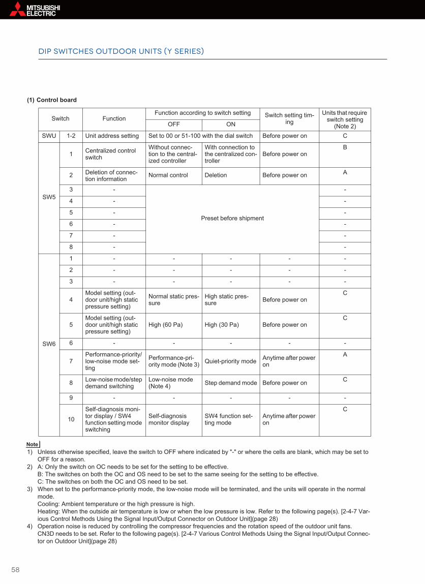
58
DIP SWITCHES OUTDOOR UNITS (Y SERIES)[5-1 Dipswitch Functions and Factory Settings ]
- 127 -HWE1314A GB
5 C
ontr
ol
5 Control
5-1 Dipswitch Functions and Factory Settings
5-1-1 Outdoor Unit Switch Functions and Factory Settings
(1) Control board
1) Unless otherwise specified, leave the switch to OFF where indicated by "-" or where the cells are blank, which may be set to OFF for a reason.
2) A: Only the switch on OC needs to be set for the setting to be effective.B: The switches on both the OC and OS need to be set to the same seeing for the setting to be effective.C: The switches on both the OC and OS need to be set.
3) When set to the performance-priority mode, the low-noise mode will be terminated, and the units will operate in the normal mode.Cooling: Ambient temperature or the high pressure is high.Heating: When the outside air temperature is low or when the low pressure is low. Refer to the following page(s). [2-4-7 Var-ious Control Methods Using the Signal Input/Output Connector on Outdoor Unit](page 28)
4) Operation noise is reduced by controlling the compressor frequencies and the rotation speed of the outdoor unit fans.CN3D needs to be set. Refer to the following page(s). [2-4-7 Various Control Methods Using the Signal Input/Output Connec-tor on Outdoor Unit](page 28)
Switch FunctionFunction according to switch setting Switch setting tim-
ingUnits that require
switch setting (Note 2)OFF ON
SWU 1-2 Unit address setting Set to 00 or 51-100 with the dial switch Before power on C
SW5
1 Centralized control switch
Without connec-tion to the central-ized controller
With connection to the centralized con-troller
Before power onB
2 Deletion of connec-tion information Normal control Deletion Before power on A
3 -
Preset before shipment
-
4 - -
5 - -
6 - -
7 - -
8 - -
SW6
1 - - - - -
2 - - - - -
3 - - - - -
4Model setting (out-door unit/high static pressure setting)
Normal static pres-sure
High static pres-sure Before power on
C
5Model setting (out-door unit/high static pressure setting)
High (60 Pa) High (30 Pa) Before power onC
6 - - - - -
7Performance-priority/low-noise mode set-ting
Performance-pri-ority mode (Note 3) Quiet-priority mode Anytime after power
on
A
8 Low-noise mode/step demand switching
Low-noise mode (Note 4) Step demand mode Before power on C
9 - - - - -
10
Self-diagnosis moni-tor display / SW4 function setting mode switching
Self-diagnosis monitor display
SW4 function set-ting mode
Anytime after power on
C

59
[5-1 Dipswitch Functions and Factory Settings ]
- 128 -HWE1314A GB
1) To change the settings, set SW6-10 to ON, set SW4, and press and hold SWP01 for 2 seconds or longer (OFF↔ON).LED3 will light up when the switch setting is ON, and lights off when OFF.Use the LED3 display to confirm that the settings are properly made.The settings will need to be set again when the control board is replaced. Write down the settings on the electrical wiring drawing label.
2) A: OC: Only the switch on OC needs to be set for the setting to be effective.B: OC: The switches on both the OC and OS need to be set to the same seeing for the setting to be effective.C: OC: The switches on both the OC and OS need to be set. D: OC: The switch on either the OC or OS needs to be set.
3) For details, refer to the following page(s).[5-2-7 Defrost Operation Control](page 139)4) The table below shows how the target evaporation temperature is set with SW4 (982).
5) Unless otherwise specified, leave the switch to OFF where indicated by "-" or where the cells are blank, which may be set to OFF for a reason.6) The settings that are configured with SW4 (SW6-10: ON) will automatically be stored on the indoor units that support the new function*. The stored
settings will automatically be restored when the outdoor unit control board is replaced.If none of the connected indoor units supports the new function, no configuration information will be saved. If this is the case, manually record the settings configuration on the control box panel.*The new function is supported on most units that are manufactured in December of 2012 and later. Depending on the model, this function may be
added on later date. Ask your dealer for further details.
Switch Function
Function according to switch setting
Switch setting timing
Units that require switch setting
(Note 2)OFF (LED3 Unlit) ON (LED3 Lit)
SW4SW6-10: OFF
1-101:ON, 0:OFF
Self-diagnosis/operation monitor
Refer to the following page(s). [9 LED Status Indicators on the Outdoor Unit Circuit Board](page 385)
Anytime after power on C
SW41-10 [0:OFF, 1:ON](Note 1)SW6-10:ON
No.769 1000000011 Test run mode: ON/OFF Stops all ICs Sends a test-run sig-nal to all IC Anytime after power on A
No.832 0000001011 Cumulative compressor operation time deletion Retained Cleared Anytime after power on (OFF→ON) C
No.848 0000101011 Continuous heating cycle function Disabled Enabled After being energized and while the com-
pressor is stopped A
No.896 0000000111 Clearance of error history
OC Retained (IC/OC) Deleted (IC/OC)Anytime after power on (OFF→ON) C
OS Retained (OS) Deleted (OS)
No.897 1000000111 High sensible heat opera-tion setting Normal control High sensible heat
operation mode Before power on A
No.912 0000100111 Pump down function Normal control Pump down opera-tion
After being energized and while the com-pressor is stopped A
No.913 1000100111 Forced defrost (Note 3) Normal control Forced defrost starts10 minutes after the completion of de-frost operation (OFF→ON) or 10 minutes after compressor start-up (OFF→ON)
D
No.915 1100100111 Defrost start temperature (Note 3)
(E)P200, (E)P250:-10°C [14°F](E)P300 - (E)P500: -8°C [18°F]
-5°C [23°F] Anytime after power on B
No.916 0010100111 Defrost end temperature (Note 3) 7°C [45°F] 12°C [54°F] Anytime after power on B
No.918 0110100111 Changes the defrost timer setting (Note 3) 50 minutes 90 minutes Anytime after power on (OFF→ON) B
No.921 1001100111 Temperature unit display °C °F Anytime after power on C
No.922 0101100111 Refrigerant amount adjust-ment Normal control Refrigerant amount
adjust mode
When the compressor is in operation (ex-cept during initial startup/becomes inef-fective 90 minutes after compressor started up.)
A
No.932 0010010111 Heating backup Disabled Enabled Anytime after power on A
No.933 1010010111 Snow sensor settingEffective only when TH7 ≤ 5 is true or the snow sensor contact input is on.
Effective when TH7 ≤ 5 is true Anytime after power on C
No.934 0110010111 Snow sensor setting Continuous fan op-eration (FAN=50%)
Refrigerant recov-ery/Evacuation (two-way valve/LEV1 open)
Anytime after power on C
No.935 1110010111 High heating power (at low outside temperature) Effective Ineffective Anytime after power on A
No.972 0011001111Automatic cooling/heating mode (IC with the smallest address)
Normal control Automatic cooling/heating mode Before power on A
No.982 0110101111 Target evaporation tem-perature setting Refer to Note 4). Anytime after power on A
SW4(982) OFF → ON → OFF → ON → OFF → ON
Target evaporatingtemperature
0 [32 ] [32 ] [32 ][25 ]
-2[28 ]
0 0-4[21 ]-6
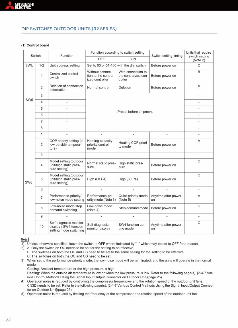
60
[5-1 Dipswitch Functions and Factory Settings ]
- 87 -HWE13130 GB
5 C
ontr
ol
5 Control
5-1 Dipswitch Functions and Factory Settings
5-1-1 Outdoor Unit Switch Functions and Factory Settings
(1) Control board
1) Unless otherwise specified, leave the switch to OFF where indicated by "-," which may be set to OFF for a reason.2) A: Only the switch on OC needs to be set for the setting to be effective.
B: The switches on both the OC and OS need to be set to the same seeing for the setting to be effective.C: The switches on both the OC and OS need to be set.
3) When set to the performance-priority mode, the low-noise mode will be terminated, and the units will operate in the normal mode.Cooling: Ambient temperature or the high pressure is high.Heating: When the outside air temperature is low or when the low pressure is low. Refer to the following page(s). [2-4-7 Var-ious Control Methods Using the Signal Input/Output Connector on Outdoor Unit](page 25)
4) Operation noise is reduced by controlling the compressor frequencies and the rotation speed of the outdoor unit fans.CN3D needs to be set. Refer to the following page(s). [2-4-7 Various Control Methods Using the Signal Input/Output Connec-tor on Outdoor Unit](page 25)
5) Operation noise is reduced by limiting the frequency of the compressor and rotation speed of the outdoor unit fan.
Switch FunctionFunction according to switch setting
Switch setting timingUnits that require
switch setting (Note 2)OFF ON
SWU 1-2 Unit address setting Set to 00 or 51-100 with the dial switch Before power on C
SW5
1 Centralized control switch
Without connec-tion to the central-ized controller
With connection to the centralized con-troller
Before power onB
2 Deletion of connection information Normal control Deletion Before power on A
3 -
Preset before shipment
-
4 - -
5 - -
6 - -
7 - -
8 - -
SW6
1 - - - - -
2COP priority setting (at low outside tempera-ture)
Heating capacity priority control mode
Heating COP priori-ty mode Before power on
A
3 - - - - -
4Model setting (outdoor unit/high static pres-sure setting)
Normal static pres-sure
High static pres-sure Before power on
C
5Model setting (outdoor unit/high static pres-sure setting)
High (60 Pa) High (30 Pa) Before power onC
6 - - - - -
7 Performance-priority/low-noise mode setting
Performance-pri-ority mode (Note 3)
Quiet-priority mode(Note 5)
Anytime after power on
A
8 Low-noise mode/step demand switching
Low-noise mode (Note 4) Step demand mode Before power on C
9 - - - - -
10Self-diagnosis monitor display / SW4 function setting mode switching
Self-diagnosis monitor display
SW4 function set-ting mode
Anytime after power on
C
DIP SWITCHES OUTDOOR UNITS (R2 SERIES)

61
[5-1 Dipswitch Functions and Factory Settings ]
- 88 -HWE13130 GB
(2) Additional dipswitch settings at time of shipment
Switch Function
Function according to switch setting
Switch setting timing
Units that require switch setting
(Note 2)OFF (LED3 Unlit) ON (LED3 Lit)
SW4SW6-10: OFF
1-101:ON, 0:OFF
Self-diagnosis/operation monitor
Refer to the following page(s). [9 LED Status Indicators on the Outdoor Unit Circuit Board](page 281)
Anytime after power on C
SW41-10 [0:OFF, 1:ON](Note 1)SW6-10:ON
No.769 1000000011 Test run mode: ON/OFF Stops all ICs Sends a test-run sig-nal to all IC Anytime after power on A
No.832 0000001011 Cumulative compressor operation time deletion Retained Cleared Any time after being energized (When
changed from OFF to ON) C
No.848 0000101011 On-cycle defrost function Disabled Enabled After being energized and while the com-pressor is stopped B
No.896 0000000111 Clearance of error history
OC Retained (IC/OC) Deleted (IC/OC)Anytime after power on (OFF→ON) C
OS Retained (OS) Deleted (OS)
No.897 1000000111 High sensible heat opera-tion setting
Depends on the combined setting with No. 900 (Note 4)
After being energized and while the com-pressor is stopped A
No.900 0010000111 High sensible heat opera-tion setting
Depends on the combined setting with No. 897 (Note 4)
After being energized and while the com-pressor is stopped A
No.912 0000100111 Pump down function Normal control Pump down opera-tion
After being energized and while the com-pressor is stopped A
No.913 1000100111 Forced defrost (Note 3) Normal control Forced defrost starts10 minutes after the completion of de-frost operation (OFF→ON) or 10 minutes after compressor start-up (OFF→ON)
D
No.915 1100100111 Defrost start temperature (Note 3)
EP200 - EP350:-13°C [9°F]EP400 - EP500:-11°C [12°F]
-8°C [18°F] Anytime after power on B
No.916 0010100111 Defrost end temperature (Note 3)
EP200 - EP250:10°C [50°F]EP300 - EP500:7°C [45°F]
5°C [41°F] Anytime after power on B
No.918 0110100111 Changes the defrost timer setting (Note 3) 50 minutes 90 minutes Anytime after power on (OFF→ON) B
No.921 1001100111 Temperature unit display °C °F Anytime after power on C
No.922 0101100111 Refrigerant amount adjust-ment Normal control Refrigerant amount
adjust modeAnytime after power on (except during initial startup/becomes ineffective 60 minutes after compressor started up.
A
No.932 0010010111 Heating backup Disabled Enabled Anytime after power on A
No.933 1010010111 Snow sensor settingEffective only when TH7 ≤ 5 is true or the snow sensor contact input is on.
Effective when TH7 ≤ 5 is true Anytime after power on C
No.934 0110010111 Snow sensor setting Continuous fan op-eration (FAN=50%)
Intermittent fan op-eration (The fan op-erates in the cycle of being in operation at 100% capacity for 5 minutes and then stops and remains stopped for 30 min-utes.)
Anytime after power on C
No.964 0010001111 Target evaporation tem-perature setting
Depends on the setting combination with No. 982 (Note 5) Anytime after power on A
No.972 0011001111Automatic cooling/heating mode (IC with the smallest address)
Normal control Automatic cooling/heating mode
Before power on (After configuring the setting, perform a power reset.) A
No.982 0110101111 Target evaporation tem-perature setting
Depends on the setting combination with No. 964 (Note 5) Anytime after power on A
No.988 0011101111Refrigerant recovery/Evac-uation (two-way valve/LEV1 open)
Disabled Enabled After being energized and when units are stopped C

62
SW5-1 Must be set to ON when using a central controller
SW5-2 Used to reset the connection history of the system.
This procedure must be used at the beginning of commissioning and at any time where there is a change or addition to the
M-Net system.
Connection memory reset procedure:
1. Power down the outdoor. Wait 1 minute
2. Turn dip switch 5-2 to ON. Power up outdoor unit. Wait 5 minutes
3. Power down outdoor unit. Wait 1 minute. Turn dip switch 5-2 to OFF
4. Power up outdoor unit and wait 5 minutes
5. Outdoor unit will now have new connection information
COMMON DIP SWITCHES
DIP SWITCHES OUTDOOR UNITS (Y and R2 SERIES)
[5-1 Dipswitch Functions and Factory Settings ]
- 89 -HWE13130 GB
5 C
ontr
ol
1) To change the settings, set SW6-10 to ON, set SW4, and press and hold SWP01 for 2 seconds or longer (OFF↔ON).LED3 will light up when the switch setting is ON, and lights off when OFF.Use the LED3 display to confirm that the settings are properly made.The settings will need to be set again when the control board is replaced. Write down the settings on the electrical wiring drawing label.
2) A: OC: Only the switch on OC needs to be set for the setting to be effective.B: OC: The switches on both the OC and OS need to be set to the same seeing for the setting to be effective.C: OC: The switches on both the OC and OS need to be set. D: OC: The switch on either the OC or OS needs to be set.
3) For details, refer to the following page(s).[5-2-7 Defrost Operation Control](page 97)4) The table below shows the combinations of the settings for items No. 897 and No. 900 and the target evaporating temperature setting that corresponds
to each combination.
5) The table below shows the combinations of the settings for items No. 964 and No. 982 and the target evaporating temperature setting that corresponds to each combination.
6) Unless otherwise specified, leave the switch to OFF where indicated by "-," which may be set to OFF for a reason.7) The settings that are configured with SW4 (SW6-10: ON) will automatically be stored on the indoor units that support the new function*. The stored
settings will automatically be restored when the outdoor unit control board is replaced.If none of the connected indoor units supports the new function, no configuration information will be saved. If this is the case, manually record the settings configuration on the control box panel.*The new function is supported on most units that are manufactured in December of 2012 and later. Depending on the model, this function may be
added on later date. Ask your dealer for further details.
(3) INV boardFunctions are switched with the following connector.1) PUHY-EP200, EP250, EP300,EP350,EP400,EP450YLM-A
CN6 short-circuit connector is mated with the mating connector. Leave the short-circuit connector on the mating connector during normal operation to enable error detection and protect the equipment from damage.
Switch No.900OFF ON
No.897 OFF 0°C [32°F] 9°C [48°F]ON 4°C [39°F] 14°C [57°F]
Switch No.982OFF ON
No.964 OFF 0°C [32°F] -4°C [25°F]ON -2°C [28°F] -6°C [21°F]
Connector FunctionFunction according to connec-
tor Setting timingEnabled Disabled
CN6 short-circuit con-
nector
Detects or ignores the following errorsACCT sensor failure(5301 Detail No. 115)ACCT sensor circuit failure(5301 Detail No.117)IPM open/ACCT erroneous wiring(5301 Detail No. 119)Detection of ACCT erroneous wiring(5301 Detail No.120)
Error detec-tion enabled
Error detec-tion disable(No load op-eration is pos-sible.)
Anytime after power on

63
DIP SWITCHES INDOOR UNITS

64
SW1-1 Change the sensing location from the return air to the wall controller.
SW1-3 Increase the filter check from 100 hours to 2500 hours.
SW1-9 Auto restart after a power cut.
SW3-8 4°C heating offset (used for ceiling mounted products to allow for stratification).
SW3-1, SW1-7, SW1-8 Change fan speed setting on the indoor unit while in the thermostat OFF position as per the
table below. This is often used to reduce drafts during the off cycle.
PLEASE NOTESome indoor units will come with 8 dip switches on SW3 rather than the 10 shown on the previous
page. If the unit comes with 8 please note that the dip switches will change as per the table below.
COMMON DIP SWITCHES
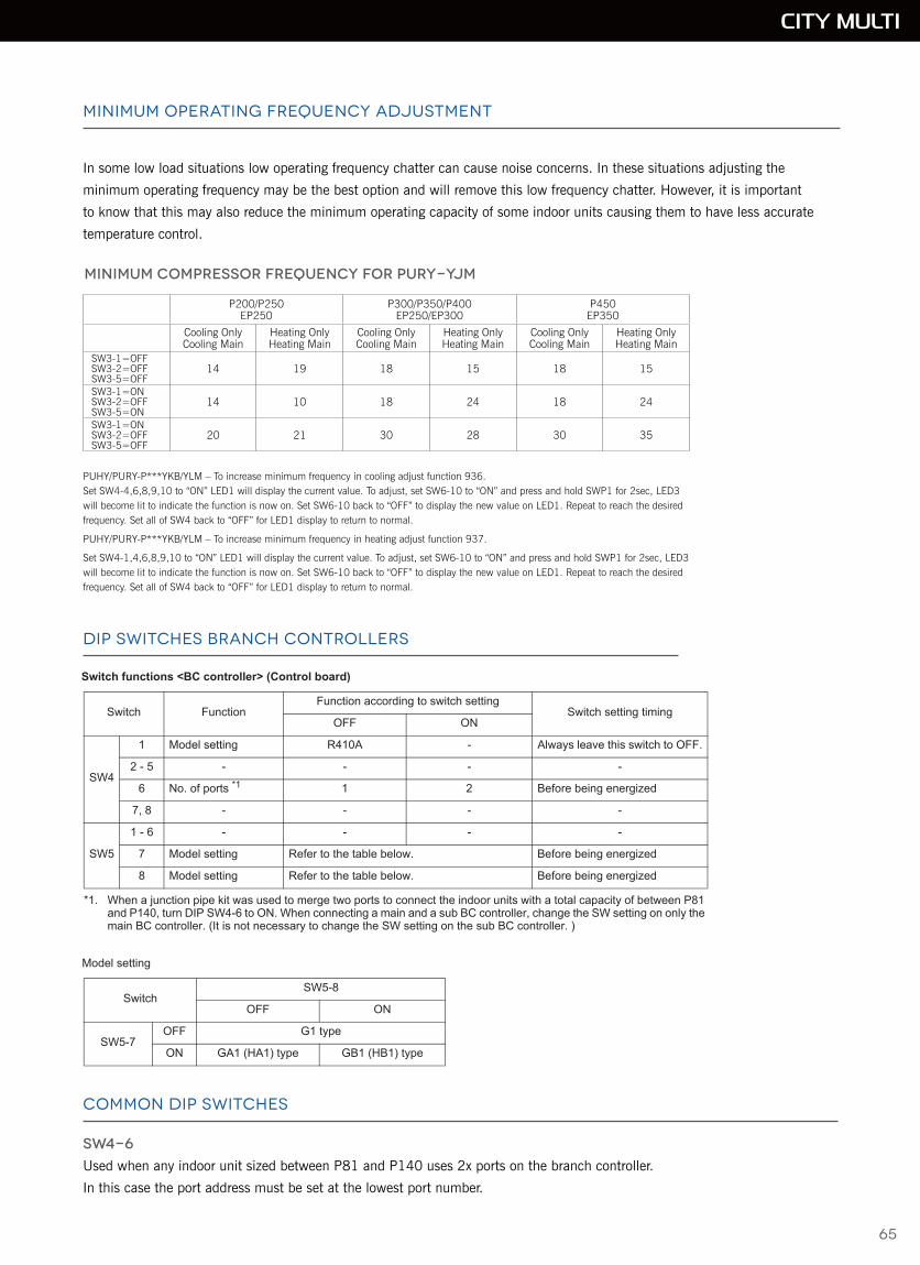
65
DIP SWITCHES BRANCH CONTROLLERS
COMMON DIP SWITCHES SW4-6Used when any indoor unit sized between P81 and P140 uses 2x ports on the branch controller.
In this case the port address must be set at the lowest port number.
Switch functions <BC controller> (Control board)
Model setting
Switch FunctionFunction according to switch setting
Switch setting timingOFF ON
SW4
1 Model setting R410A - Always leave this switch to OFF.
----5 - 2
6 No. of ports *1
*1. When a junction pipe kit was used to merge two ports to connect the indoor units with a total capacity of between P81 and P140, turn DIP SW4-6 to ON. When connecting a main and a sub BC controller, change the SW setting on only the main BC controller. (It is not necessary to change the SW setting on the sub BC controller. )
dezigrene gnieb erofeB21
----8 ,7
SW5
----6 - 1
dezigrene gnieb erofeB .woleb elbat eht ot refeRgnittes ledoM7
dezigrene gnieb erofeB .woleb elbat eht ot refeRgnittes ledoM8
SwitchSW5-8
OFF ON
SW5-7OFF G1 type
ON GA1 (HA1) type GB1 (HB1) type
In some low load situations low operating frequency chatter can cause noise concerns. In these situations adjusting the
minimum operating frequency may be the best option and will remove this low frequency chatter. However, it is important
to know that this may also reduce the minimum operating capacity of some indoor units causing them to have less accurate
temperature control.
P200/P250EP250
P300/P350/P400EP250/EP300
P450EP350
Cooling OnlyCooling Main
Heating OnlyHeating Main
Cooling OnlyCooling Main
Heating OnlyHeating Main
Cooling OnlyCooling Main
Heating OnlyHeating Main
SW3-1=OFFSW3-2=OFFSW3-5=OFF
14 19 18 15 18 15
SW3-1=ONSW3-2=OFFSW3-5=ON
14 10 18 24 18 24
SW3-1=ONSW3-2=OFFSW3-5=OFF
20 21 30 28 30 35
PUHY/PURY-P***YKB/YLM – To increase minimum frequency in cooling adjust function 936. Set SW4-4,6,8,9,10 to “ON” LED1 will display the current value. To adjust, set SW6-10 to “ON” and press and hold SWP1 for 2sec, LED3 will become lit to indicate the function is now on. Set SW6-10 back to “OFF” to display the new value on LED1. Repeat to reach the desired frequency. Set all of SW4 back to “OFF” for LED1 display to return to normal.
PUHY/PURY-P***YKB/YLM – To increase minimum frequency in heating adjust function 937.
Set SW4-1,4,6,8,9,10 to “ON” LED1 will display the current value. To adjust, set SW6-10 to “ON” and press and hold SWP1 for 2sec, LED3 will become lit to indicate the function is now on. Set SW6-10 back to “OFF” to display the new value on LED1. Repeat to reach the desired frequency. Set all of SW4 back to “OFF” for LED1 display to return to normal.
MINIMUM COMPRESSOR FREQUENCY FOR PURY-YJM
Minimum operating frequency adjustment

66
S, Y and WY series units all have the ability to automatically change operating mode from heating to cooling.
There are a number of auto changeover options depending on the system controllers or application.
1. Factory settings
There is no auto changeover available.
The first indoor unit to operate will select the operation mode of the outdoor unit (heating or cooling). The outdoor unit will
remain in this mode until all indoor units are either turned off or have been selected to operate in the opposite mode.
2. Auto changeover - selected from the outdoor unit
This feature will put the indoor unit that has been set to the lowest M-Net address as the master unit. Auto mode will become
available through the wall controller and the outdoor unit will change operation mode (heating or cooling) based on this units’
heating or cooling requirements. All other indoor units will display the same operation mode as this lead unit.
PUHY-P***YHM/YJM set SW4-5 to the “ON” position on the outdoor control board.
PUHY-P***YKB/YLM function 781 set SW6-10 “ON” then SW4-1,3,4,9,10 to “ON” and press and hold SWP1 for 2 sec
LED3 will become lit to indicate the function is now on.
Set SW6-10 back to “OFF”.
PUMY-P***(V)YHMB set SW2-5 to the “ON” position on the outdoor control board.
PUMY-P***VKM set SW9-1 to the “ON” position on the outdoor control board.
3. Auto changeover – selected from the central controller with web browser
This is only available on central controllers that have a web browser feature.
Using one of these controllers gives two additional auto changeover control options.
• Weighted average This looks at the heating and cooling demand of all indoor units within the system at a 15 minute interval. Once the total demand for the opposite operation mode is greater than 50% the outdoor unit will switch operation mode (heating or cooling).
• Represented group This feature allows you to select any group as the master. The lowest addressed unit within the group will decide whether the system will operate in heating or cooling mode based on the heating or cooling requirements of that unit. The wall controller will display heat or cool (not auto) but will automatically change when the temperature requirements are calling for the opposite mode. All other indoor units will display the same operation mode as this lead group.
Auto changeover - S, Y, WY Series only

67
Rotary switch
Branch No. setting Unit address No. setting
0123456789ABCD
EF
INDOOR UNIT INSTALLATION SETTINGS
The loose pages in the back of this booklet have indoor unit setting information. These pages must be completed prior to BDT
attending site for commissioning. If additional installation setting sheets are required please contact your BDT sales representative.
MODEL:
SERIAL:
GROUP NAME:
Please circle the address and dip switch settings
0 1 23
45678
9 0 1 23
45678
9
Switch FunctionFunction according to switch setting Switch setting timing
OFF ON OFF ON
SW1
1 Room temperature detection position Indoor unit inlet Built-in sensor on the remote controller
While the unit is stopped (Remote controller OFF)
2 Clogged filter detection Not available Available
3 Filter check reminder time setting 100h 2500h
4 Outside air intake Disabled Enabled
5 Remote display option Fan output Thermo - ON signal
6 Humidifier control During heating operation
Always on while in the heating mode
7Fan speed setting for Heating Thermo - OFF Very low Low
Forced heating operation at OA temp of 5°C or below Not available Available
8Fan speed setting for Heating Thermo - OFF According to the
SW1-7 setting Pre-set speed
- - -
9 Self-recovery after power failure Disabled Enabled
10 Power source start-stop Disabled Enabled
SW3
1 Unit model selection Heat pump Cooling only
2 Louvre Not available Available
3 Vane Not available Available
4 Vane swing function Not available Available
5 - - -
6Vane angle limit setting for cooling operation Down blow B,C Horizontal
Initial vane position Enabled Disabled
7 Automatic LEV value conversion function Not available Available
8 Heating 4°C [7.2°F] up Enabled Disabled
9 SHm setting 2°C [3.6°F] 5°C [9°F]
10 SCm setting 10°C [18°F] 15°C [27°F]
Quote Number
Job Name
INDOOR UNIT INSTALLATION SETTINGS template

68
Stanley Street Building, Auckland