Nortel CS1000 Release 5.0 to Cisco Unified Communications ...

Cisco Unified ICM ACD Supplement for Nortel Symposium August 2011
Corporate Headquarters Cisco Systems, Inc. 170 West Tasman Drive San Jose, CA 95134-1706 USA http://www.cisco.com Tel: 408 526-4000 800 553-NETS (64387) Fax: 408 526-4100

THE SPECIFICATIONS AND INFORMATION REGARDING THE PRODUCTS IN THIS MANUAL ARE SUBJECT TO CHANGE WITHOUT NOTICE. ALL STATEMENTS, INFORMATION, AND RECOMMENDATIONS IN THIS MANUAL ARE BELIEVED TO BE ACCURATE BUT ARE PRESENTED WITHOUT WARRANTY OF ANY KIND, EXPRESS OR IMPLIED. USERS MUST TAKE FULL RESPONSIBILITY FOR THEIR APPLICATION OF ANY PRODUCTS. THE SOFTWARE LICENSE AND LIMITED WARRANTY FOR THE ACCOMPANYING PRODUCT ARE SET FORTH IN THE INFORMATION PACKET THAT SHIPPED WITH THE PRODUCT AND ARE INCORPORATED HEREIN BY THIS REFERENCE. IF YOU ARE UNABLE TO LOCATE THE SOFTWARE LICENSE OR LIMITED WARRANTY, CONTACT YOUR CISCO REPRESENTATIVE FOR A COPY.
The Cisco implementation of TCP header compression is an adaptation of a program developed by the University of California, Berkeley (UCB) as part of UCB’s public domain version of the UNIX operating system. All rights reserved. Copyright © 1981, Regents of the University of California.
NOTWITHSTANDING ANY OTHER WARRANTY HEREIN, ALL DOCUMENT FILES AND SOFTWARE OF THESE SUPPLIERS ARE PROVIDED “AS IS” WITH ALL FAULTS. CISCO AND THE ABOVE-NAMED SUPPLIERS DISCLAIM ALL WARRANTIES, EXPRESSED OR IMPLIED, INCLUDING, WITHOUT LIMITATION, THOSE OF MERCHANTABILITY, FITNESS FOR A PARTICULAR PURPOSE AND NONINFRINGEMENT OR ARISING FROM A COURSE OF DEALING, USAGE, OR TRADE PRACTICE.
IN NO EVENT SHALL CISCO OR ITS SUPPLIERS BE LIABLE FOR ANY INDIRECT, SPECIAL, CONSEQUENTIAL, OR INCIDENTAL DAMAGES, INCLUDING, WITHOUT LIMITATION, LOST PROFITS OR LOSS OR DAMAGE TO DATA ARISING OUT OF THE USE OR INABILITY TO USE THIS MANUAL, EVEN IF CISCO OR ITS SUPPLIERS HAVE BEEN ADVISED OF THE POSSIBILITY OF SUCH DAMAGES.
CCDE, CCENT, CCSI, Cisco Eos, Cisco HealthPresence, Cisco IronPort, the Cisco logo, Cisco Lumin, Cisco Nexus, Cisco Nurse Connect, Cisco Pulse, Cisco StackPower, Cisco StadiumVision, Cisco TelePresence, Cisco Unified Computing System, Cisco WebEx, DCE, Flip Channels, Flip for Good, Flip Mino, Flipshare (Design), Flip Ultra, Flip Video, Flip Video (Design), Instant Broadband, and Welcome to the Human Network are trademarks; Changing the Way We Work, Live, Play, and Learn, Cisco Capital, Cisco Capital (Design), Cisco:Financed (Stylized), Cisco Store, and Flip Gift Card are service marks; and Access Registrar, Aironet, AllTouch, AsyncOS, Bringing the Meeting To You, Catalyst, CCDA, CCDP, CCIE, CCIP, CCNA, CCNP, CCSP, CCVP, Cisco, the Cisco Certified Internetwork Expert logo, Cisco IOS, Cisco Press, Cisco Systems, Cisco Systems Capital, the Cisco Systems logo, Cisco Unity, Collaboration Without Limitation, Continuum, EtherFast, EtherSwitch, Event Center, Explorer, Fast Step, Follow Me Browsing, FormShare, GainMaker, GigaDrive, HomeLink, iLYNX, Internet Quotient, IOS, iPhone, iQuick Study, IronPort, the IronPort logo, Laser Link, LightStream, Linksys, MediaTone, MeetingPlace, MeetingPlace Chime Sound, MGX, Networkers, Networking Academy, Network Registrar, PCNow, PIX, PowerKEY, PowerPanels, PowerTV, PowerTV (Design), PowerVu, Prisma, ProConnect, ROSA, ScriptShare, SenderBase, SMARTnet, Spectrum Expert, StackWise, The Fastest Way to Increase Your Internet Quotient, TransPath, WebEx, and the WebEx logo are registered trademarks of Cisco Systems, Inc. and/or its affiliates in the United States and certain other countries.
All other trademarks mentioned in this document or website are the property of their respective owners. The use of the word partner does not imply a partnership relationship between Cisco and any other company. (1002R)
Cisco Unified ICM ACD Supplement for Nortel Symposium Copyright © 2010, Cisco Systems, Inc. All rights reserved.

Contents
Contents ............................................................................... iii
Preface ................................................................................... 9
1. Overview ....................................................................... 13
1.1. ACD Interface Requirements .......................................................... 14 1.1.1. Symposium ACD Scripts ....................................................... 15 1.1.2. Symposium ACD Applications and Skill Sets ....................... 15 1.1.3. Swap Feature in Symposium ACD ....................................... 16 1.1.4. Hardware and Software Requirements ................................. 19 1.1.5. Special Requirements ........................................................... 20 1.1.6. Supported Unified ICM Software Features ........................... 20 1.1.7. Multiple Application Support .................................................. 20 1.1.8. General Restrictions .............................................................. 20 1.1.9. CTI Server Restrictions ......................................................... 22
1.2. Symposium PG Platform Requirements ........................................ 23
1.3. Upgrading from Symposium 1.5 to Symposium 3.0 ........................................................................... 23
1.4. Upgrading from Symposium 1.5 or 3.0 to Symposium 4.0 .................................................................. 24
1.5. Upgrading from Symposium 1.5, 3.0, or 4.0 to Symposium 4.2 ............................................................ 24
1.6. Upgrading from Symposium 4.0 or 4.2 to Symposium 5.0 ................................................................... 25
1.7. Working with Unified ICM SRs and ESs ........................................ 25
2. ACD Configuration ....................................................... 27
2.1. Configuration Prerequisites ............................................................ 28
2.2. Script Modifications for Call Processing ....................................... 28 2.2.1. Arrived ................................................................................... 29 2.2.2. Interflowed ............................................................................. 30

iv Contents
2.2.3. Enqueued .............................................................................. 31 2.2.4. Enqueued_MLA .................................................................... 31 2.2.5. Enqueued_MLA_Begin, Enqueued_MLA_Next, Enqueued_MLA_End ...................... 31 2.2.6. Enqueued_Agent .................................................................. 32 2.2.7. Dequeued .............................................................................. 32 2.2.8. Dequeued_Agent .................................................................. 32 2.2.9. NACD_Queued ..................................................................... 32 2.2.10. NACD_Ping ........................................................................... 33 2.2.11. NACD_Dequeued ................................................................. 34 2.2.12. Routed ................................................................................... 34 2.2.13. Give_Busy ............................................................................. 35 2.2.14. Give_Overflow ....................................................................... 36 2.2.15. Controlled_Returned ............................................................. 36 2.2.16. Disconnect ............................................................................. 36
2.3. Script Modifications for Post-Routing ........................................... 36
2.4. Meridian 1 Configuration ................................................................. 36
2.5. IVR Port Configuration and Considerations ................................. 37
2.6. Meridian Mail Considerations ......................................................... 37
2.7. NCCM Server Capacity Considerations ..................................................... 38
3. Web Setup Tool and Configuration ............................ 39
3.1. Web Setup Tool ................................................................................ 40 3.1.1. Installing the Symposium PG ................................................ 40 3.1.2. Meridian Link Configuration .................................................. 42 3.1.3. RTD Configuration ................................................................ 43 3.1.4. HDX Configuration ................................................................ 43
3.2. Unified ICM Software Configuration .............................................. 43 3.2.1. Peripheral Configuration ....................................................... 44 3.2.2. Peripheral Target Configuration ............................................ 44 3.2.3. Trunk Group Configuration .................................................... 45 3.2.4. Trunk Configuration ............................................................... 46 3.2.5. Service Configuration ............................................................ 46 3.2.6. Skill Group Configuration ...................................................... 46 3.2.7. Service Member Mappings ................................................... 47 3.2.8. Agent Configuration .............................................................. 47 3.2.9. Agent State Mapping ............................................................. 48 3.2.10. Skill Group Member Mappings .............................................. 48 3.2.11. Translation Routes ................................................................ 49 3.2.12. Route Configuration .............................................................. 49 3.2.13. Routing Client Configuration ................................................. 49 3.2.14. Peripheral Monitor Configuration of Symposium CDNs ........ 49 3.2.15. Peripheral Monitor Configuration of Symposium Positions ... 49
3.3. IVR Port Configurations .................................................................. 51
Contents v
3.4. Activity Code Configuration ........................................................... 51 3.4.1. Unified ICM Configuration .................................................... 51 3.4.2. CTI OS Server Configuration ................................................ 51 3.4.3. Meridian PBX and SCCS Configuration ................................ 52
3.5. Special Considerations in NAM Environments ............................. 52
3.6. Maintaining Your Configuration ..................................................... 52
4. Post-Routing ................................................................. 55
4.1. Changes to the Nortel Contact Center Manager server Configuration ........................................... 56
4.1.1. Reserve CDNs or DNISs ....................................................... 56 4.1.2. DO_POST_ROUTE Section of Master Script ....................... 56 4.1.3. Example of Post-Routing Section in Master Script ............... 58
4.2. Changes to the Unified ICM Software Configuration ................... 61 4.2.1. Labels .................................................................................... 61 4.2.2. Call Control Variable Map ..................................................... 61
4.3. Caller Entered Digits ....................................................................... 62
4.4. Translation Routing ......................................................................... 62 4.4.1. Review of How To Configure Translation Routes ................. 62 4.4.2. Symposium Post-Routed Translation Routes ....................... 63
5. ACD-Specific Interpretation of Unified ICM Software Data ........................................... 65
5.1. Method of Attributing Calls to Services......................................... 66
5.2. Method of Attributing Calls to Skill Groups .................................. 66
5.3. Calculation of Handle Time ............................................................. 66
5.4. Handling of ROUTE CALL Script Command ................................. 67
5.5. Handling of ROUTE CALL CONTROLLED Script Command ..................................................... 67
5.6. Handling of QUEUE TO NACD Script Command .......................... 68
5.7. Handling of GIVE BUSY Script Command ..................................... 69
5.8. Handling of GIVE BUSY CONTROLLED Script Command .................................................... 69
5.9. Handling of GIVE OVERFLOW Script Command .......................... 69
5.10. Handling of GIVE OVERFLOW CONTROLLED Script Command ........................................................... 70

vi Contents
5.11. Handling of DISCONNECT Script Command .............................. 70
5.12. Handling of Trunk Group Statistics ............................................. 70
5.13. Enhancements to the Dialed Number List Tool .......................... 70
6. Media Blender Configuration for Nortel Symposium ................................................. 71
6.1. Key Property Files............................................................................ 72 6.1.1. Blender.Properties ................................................................ 72 6.1.2. ACD.ciscocti.properties ......................................................... 73 6.1.3. Collaboration.properties ........................................................ 75 6.1.4. Phantoms.properties ............................................................. 75 6.1.5. <Connection_CMB>.properties ............................................. 75 6.1.6. Service.FWGW.properties .................................................... 76 6.1.7. FirewallGateway.properties ................................................... 76 6.1.8. Resource.Properties ............................................................. 78
6.2. Voice and Chat CTI Call Strategies ................................................ 80 6.2.1. Voice Call Strategies ............................................................. 80 6.2.2. Chat Session Strategies ........................................................ 80 6.2.3. CTI Strategies for Nortel Symposium ................................... 80 6.2.4. Routing Address and Routing Numbers ............................... 81
6.3. Configuring the Symposium Switch .............................................. 81
6.4. Testing the Symposium Switch ...................................................... 82 6.4.1. Create a Unified WIM Agent for the Nortel Symposium Switch ............................................... 82 6.4.2. Log in a Blended Collaboration Agent
on a Symposium Phone ........................................................ 83 6.4.3. Make a Blended Collaboration Caller
Request to a Symposium Agent/Phone ................................ 84 6.4.4. Log In an Agent on a Nortel Symposium Phone ................... 84 6.4.5. Place a call on a Nortel Symposium Phone .......................... 84 6.4.6. Transfer a Call on a Nortel Symposium Phone ..................... 85 6.4.7. Place a Conference Call on a
Nortel Symposium Phone ...................................................... 85 6.4.8. Making an Agent Not Ready ................................................. 85
7. SEI Lite Interface with Nortel Symposium .................. 87
7.1. Supporting Agent Re-skilling at Unified ICM Software ...................................................................... 88
7.2. Using the SEI Lite Feature with AAS.............................................. 88 7.2.1. Minimum System Requirements ........................................... 89 7.2.2. Known Limitations of the SEI Lite Feature ............................ 89
Index ........................................................................... Index-1

Contents vii

viii Contents
Tables Table 1: Symposium ACD Requirements ........................................................... 19 Table 2: Symposium-to-ICM Agent State Mapping ............................................ 46Table 3: Param String Format Examples ............................................................ 48
Figures Figure 1: Symposium Hardware Configuration ................................................... 14 Figure 2: Unified ICM
Software Setup pre-4.5 (for
Symposium ACD 1.5) ........................................................................ 38Figure 3: Unified ICM
Software Setup 4.5 (for Symposium
ACD 1.5 and 3.0) ............................................................................... 39Figure 4: Unified ICM
Software Setup 4.5, SP1 (for
Symposium ACD 1.5, 3.0, or 4.0/4.2) ................................................ 39

Preface
Purpose This document contains the specific information you need to maintain a Symposium Peripheral Gateway (PG) in a Cisco Unified Contact Center Enterprise (Unified CCE) environment. It is intended to be used as the Symposium-specific companion to the Cisco Unified ICM software documentation set. While other Unified ICM documents (for example, the Configuration Guide for Cisco Unified ICM/Contact Center Enterprise & Hosted) cover general topics such as configuring an overall Unified ICM system and writing scripts to route contact center requests, the Cisco Unified ICM ACD Supplement for Nortel Symposium provides specific information on configuring a Symposium PG and making any necessary adjustments to the Symposium ACD configuration.
Audience This document is intended for Unified ICM system managers. The reader should understand functions of the Unified ICM software as described in the following documents:
1. Installation Guide for Cisco Unified ICM/Contact Center Enterprise & Hosted
2. Configuration Guide for Cisco Unified ICM/Contact Center Enterprise & Hosted
3. Scripting and Media Routing Guide for Cisco Unified ICM/Contact Center Enterprise & Hosted
The reader should also have specific knowledge of the Nortel Symposium ACD.
Organization Chapter 1, “Overview”
Provides an overview of ACD interface and hardware and software requirements.
Chapter 2, “ACD Configuration” Describes items in the Symposium configuration that must be changed to ensure compatibility with Unified ICM.
Chapter 3, “Web Setup Tool and Configuration”
10 Preface
Provides specific information on setting up a Symposium PG by using the Web Setup tool, and configuring a Symposium PG by using the Unified ICM configuration tools. This chapter also describes the relationships between the Symposium ACD objects and the Unified ICM database objects.
Chapter 4, “Post-Routing” Describes the changes you must make to Unified ICM configuration, the Nortel Contact Center Manager (NCCM) server configuration, and the NCCM server scripts in order to post-route calls using the Symposium PG.
Chapter 5, “ACD-Specific Interpretation of Unified ICM Data” Discusses the issues you might face when you attempt to compare the Unified ICM database reporting elements and Symposium ACD reporting elements.
Chapter 6, “Media Blender Configuration for Nortel Symposium” Describes what you need to know and do to configure the Cisco Media Blender for use with the Nortel Symposium ACD (for releases prior to ICM 8.0). Note: From ICM 8.0 onwards, Cisco Media Blender is not supported with Nortel Symposium ACD.
Chapter 7, “SEI Lite Interface with Nortel Symposium” Outlines what the Symposium Event Link (SEI Lite) feature is about and how it interfaces between the Automated Administrator for Symposium (AAS) and the NCCM server.
Typographic Conventions This manual uses the following conventions: Boldface type is used for emphasis; for example:
Real-time information is not stored in the central database. Italic type indicates one of the following: A newly introduced term; for example:
A skill group is a collection of agents who share similar skills. A generic syntax item that you must replace with a specific value; for
example: IF (condition, true-value, false-value)
A title of a publication; for example: For more information see the following guides:

Preface 11
Installation and Configuration Guide for Cisco Unified Contact Center Enterprise & Hosted
Installation Guide for Cisco Unified ICM/Contact Center Enterprise & Hosted
Sans serif type with small caps is used to represent keys on your keyboard; for example: Press the SHIFT key to select a range of items.
An arrow (→) indicates an item from a pull-down menu. For example, the Save command from the File menu is referenced as File→Save.
Other Publications For more information on the Unified ICM software, see the following documents: Administration Guide for Cisco Unified ICM/Contact Center
Enterprise & Hosted Installation and Setup Guide for Cisco Unified ICM Enterprise Configuration Guide for Cisco Unified ICM/Contact Center
Enterprise & Hosted Product Description Guide for Cisco Unified ICM Hosted Scripting and Media Routing Guide for Cisco Unified ICM Enterprise For information on Cisco Network Applications Manager (NAM), see the following documents: Cisco Network Applications Manager (NAM) Product Description Multiple-NAM Setup and Configuration Guide for Cisco Unified ICM
Hosted For information on Automated Administrator for Symposium (AAS), see: Cisco Unified ICM Automated Administrator for Symposium (AAS)
Installation and Troubleshooting Guide
Obtaining Documentation, Obtaining Support and Security Guidelines
For information on obtaining documentation, obtaining support, security guidelines, and also recommended aliases and general Cisco documents, see the monthly What’s New in Cisco Product Documentation, which also lists all new and revised Cisco technical documentation, at: http://www.cisco.com/en/US/docs/general/whatsnew/whatsnew.html

12 Preface
Documentation Feedback You can provide comments about this document by sending email to the following address: [email protected] We appreciate your comments.

1. Overview
The Symposium PG communicates with the Nortel Contact Center Manager (NCCM) server to obtain call and agent state information. Specifically, the PG communicates with the NCCM server by using three interfaces. All three interfaces are required by the PG: Meridian Link Interface (MLink). This interface is used to obtain
information about call state. It also supplements the agent state information provided by the RTD interface and implements third-party call and agent control.
Host Data Exchange Interface (HDX). This interface is used to supplement the call state information provided by the MLink interface. It is also used to implement software post-routing.
Real Time Data Interface (RTD). This interface is used to obtain information about agent state. It also supplements the call state information provided by the Meridian Link Interface.
The software to support these interfaces runs on the NCCM server. This chapter provides an overview of the Symposium ACD interface, and presents the hardware and software requirements for Symposium ACD (required to interact with the software).
14 Overview
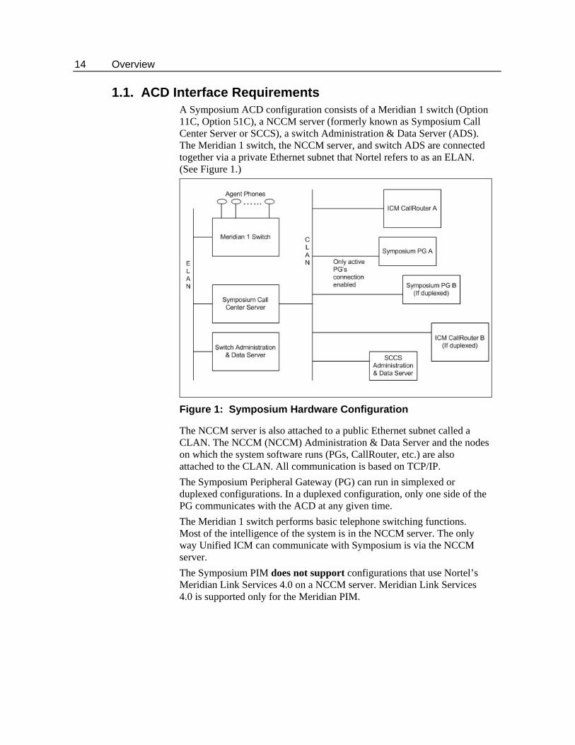
1.1. ACD Interface Requirements A Symposium ACD configuration consists of a Meridian 1 switch (Option 11C, Option 51C), a NCCM server (formerly known as Symposium Call Center Server or SCCS), a switch Administration & Data Server (ADS). The Meridian 1 switch, the NCCM server, and switch ADS are connected together via a private Ethernet subnet that Nortel refers to as an ELAN. (See Figure 1.)
Figure 1: Symposium Hardware Configuration
The NCCM server is also attached to a public Ethernet subnet called a CLAN. The NCCM (NCCM) Administration & Data Server and the nodes on which the system software runs (PGs, CallRouter, etc.) are also attached to the CLAN. All communication is based on TCP/IP. The Symposium Peripheral Gateway (PG) can run in simplexed or duplexed configurations. In a duplexed configuration, only one side of the PG communicates with the ACD at any given time. The Meridian 1 switch performs basic telephone switching functions. Most of the intelligence of the system is in the NCCM server. The only way Unified ICM can communicate with Symposium is via the NCCM server. The Symposium PIM does not support configurations that use Nortel’s Meridian Link Services 4.0 on a NCCM server. Meridian Link Services 4.0 is supported only for the Meridian PIM.

ACD Interface Requirements 15
While configuring the Network Interface Controller (NIC) cards and switch ports, ensure that: The speed and duplexity of the PGs and switch are set to 100Mbps/full
duplex. The network bindings on the PGs have the visible network listed first.
See also: For more information on the Meridian Link Services 4.0 and Meridian PIM configuration, see the Cisco Unified ICM ACD Supplement for Nortel Meridian.
1.1.1. Symposium ACD Scripts In a Symposium ACD, all calls are processed by scripts that are written by call center administrators and run on the NCCM server1
Every call being handled by a NCCM server system is sent to the master script. This script typically functions as a filter that invokes other scripts to handle the call, depending on the nature of the call and status of call center resources. A script that is directly invoked by the master script is called a primary script. A primary script may, in turn, invoke secondary scripts to handle some of the processing.
. These scripts determine caller attributes and make call treatment and queuing decisions for each call.
For a call to be handled by the NCCM server, it must terminate on a Meridian 1 Controlled DN (CDN) that has been acquired by the NCCM server. That is, the switch must be configured to associate CDNs with the NCCM server. Calls to switch resources that have not been acquired by the NCCM server will not be seen by the NCCM server2
1.1.2. Symposium ACD Applications and Skill Sets
. Any number of CDNs can be acquired by the NCCM server. A call terminating on any of these will invoke the same master script, which will then determine how the call will be handled.
The activity undertaken by a primary script and its subordinate secondary scripts is referred to as an application. All primary scripts and the master
1 NCCM Server scripts (formerly known as SCCS scripts) are completely distinct
from CallRouter scripts. NCCM Server scripts run on the NCCM Server. They determine how a call is processed once it arrives at the server. For pre-routed calls, CallRouter scripts determine which Meridian 1 trunk group and DNIS the call is presented to. The Meridian 1 switch passes this information on to the NCCM Server when it delivers the call to the server. The NCCM Server scripts can then use the information to help make call processing decisions. For post-routed calls, CallRouter scripts determine what response type and response value are returned to the NCCM Server script that made the post-route request. (See Chapter 4 for more information on Post-Routing.)
2 For example, a call center might have a Meridian switch that is configured with ACD-DNs (ACD queues) as well as NCCM Server CDNs.

16 Overview
script have corresponding applications against which performance information is gathered. For example, a call center might have two scripts in addition to the master script, perhaps a “Sales script” and a “Service script.” All performance information (e.g., calls answered, calls abandoned) for calls being handled by the Sales script are pegged against the corresponding Sales application. Note that the application associated with a call is determined by the first primary script that is executed for that call. That is, the application associated with a call does not change if the first primary script transfers control to another primary script. A NCCM server system implements skills-based routing through skill set assignment. Agents can be assigned to multiple skill sets, and calls can be queued to multiple skill sets1
1.1.3. Swap Feature in Symposium ACD
.
The Swap feature enables the agents to swap, or exchange between the customer calls and the consult calls, both from hardphones as well as softphones. The Swap feature deploys a CTI toolbar with Unified ICM, offering most of the phone set functionalities. One of the most important functionalities is that it allows the agent to swap or alternate between primary and consult calls during a Consultation Call. The agent performing the transfer must carry out a swap, or alternate between the primary key (ACD or DN) and the secondary key of transfer. On the phone set, a swap can be performed by using the transfer or primary key of the used line (ACD or DN).
Note: The Swap feature is supported from the following ICM versions: 05.0(00) SR13(00), 07.0(00) SR02(00), 06.0(00) SR05(00). The Swap feature is not supported when CTI OS is used with the Symposium ACD.
1 Calls are no longer queued to ACD-DNs as they were in previous Nortel
products.

ACD Interface Requirements 17
Dependencies and patches for the Swap feature support in SoftPhones and HardPhones:
The following patches are required for Swap feature support on: Symposium SCCS 5.0: SU 05 SUS0501/02/03 NN_SCCS_5.0_DP_050302_S [mandatory] NN_SCCS_5.0_DP_050301_S [optional] NCCM 6.0: SU03 SUS0301 PEP_030130_RU Meridian Option11C switch with Release 25.40B: MPLR18683 MPLR20429 MPLR19115
Nortel CS1000 Succession 4.0 or 4.5: MPLR20429 MPLR21764
Enabling Swap Feature on Meridian PBX The Swap feature must be enabled for the respective Agent sets at the Meridian switch. The AHA (Automatic hold allowed) class of service must be enabled for the respective Agent sets. Following are the commands to be executed to enable this feature at the Meridian switch. 1. Login to Meridian ACD 2. At the prompt enter 3. ld 20
REQ> PRT > DNB > 4001
4. Get the TN number (E.g. 5 0 00 0X) 5. Enable the feature for the TN
REQ > CHG (change) TYPE > 2616 (Teleset type) TN > 5 X (TN no. for the DN 4XXX) ECHG yes

18 Overview
ITEM > cls aha (code to enable feature) >**** (to save and exit)
Note: Meridian Option11C switch with Release 25.40B is no longer supported
with Unified ICM. For the latest and updated information on Unified ICM-ACD supportability, refer Cisco Unified ICM Supported Switches (ACDs) at: http://www.cisco.com/en/US/products/sw/custcosw/ps1001/prod_technical_reference_list.html
Enabling Swap Feature on Unified ICM
The Swap feature can be enabled with the help of Config REGISTRY Key called NortelSwapPatchInstalled. This key is created when the patch is installed. Set the value of this registry key to 1 before starting the PG. If there are multiple instances of symposium PG in the same box, the registry NortelSwapPatchInstalled needs to be set it to 1 for all the PG instances. This allows the CTIOS server to enable the alternate button on the client desktop.

ACD Interface Requirements 19
1.1.4. Hardware and Software Requirements To work with the system software, the Symposium must be configured with the hardware and software listed in Table 1.
Table 1: Symposium ACD Requirements
Releases Supported For specific release information for Symposium, see the Cisco Unified ICM Supported Switches (ACDs) document, located at Cisco.com.
Note: The software on the Meridian 1 switch must be compatible with the release of Symposium.
Meridian Link Server Requirements
The Meridian Link Server must be equipped with the following options:
- Host Enhanced Routing - In-Bound Call Management - Out-Bound Call Management
Meridian 1 Requirements
The Meridian 1 must be equipped with enough Associate Set Assignment (AST) licenses so that all ACD positions can be configured as AST. Consult your Nortel representative to ensure that you have the appropriate level of AST support installed through Incremental Software Management (ISM).
ACD Interface Requirements
The Symposium must support the following interfaces. The Symposium PG requires all three of them:
Meridian Link Interface (MLink) Real-Time Data (RTD) Host Data Exchange (HDX)
20 Overview
1.1.5. Special Requirements The HDX interface requires that the NCCM server scripts be modified
to include SEND INFO commands that notify Unified ICM when a call state transition occurs. (See Chapter 2, “ACD Configuration,” for more information.)
You must set up the Nortel HDX and RTD client communications environment on the machine on which the Symposium PG will run. (See “Symposium PG Platform Requirements,” later in this chapter for more information.)
For an agent to login successfully (either manually or through a CTI application), the phone has to be in “Off Hook” mode.
1.1.6. Supported Unified ICM Software Features The Symposium PG supports the following software features: Pre-Routing Post-Routing Enterprise CTI (includes third-party call control) Agent Reporting Duplexed PG implementation SEI Lite Interface with NCCM server along with Automated
Administrator for Symposium “(AAS)”. 1
1.1.7. Multiple Application Support
The current release of the Nortel HDX software allows only one application at a time to use the HDX interface. Therefore, you cannot run any other application that uses the HDX interface while the software is running.
1.1.8. General Restrictions Peripheral service level reporting is not supported by the Symposium
PG. Due to limitations in the Nortel interfaces, the Symposium PG does
not support the system software Trunk Group real-time data elements or Trunk Group half-hour data elements.
Using Network ACD to divert calls to another NCCM server system will cause Unified ICM to report inaccurate data because the NCCM server does not report the progress of these calls to the PG. Therefore, it is recommended not to use the QUEUE TO NACD command in your NCCM server scripts.
You must not specify an NACD DN1
1 AAS supports ICM Releases 5.0(0) and 6.0(0).
as the target of a ROUTE CALL command in your NCCM server scripts. If you must use NACD DNs,
ACD Interface Requirements 21
use the QUEUE TO NACD command – understanding that Unified ICM software reporting will then be inaccurate, as mentioned in the preceding bullet. However, the recommendation is that you find an alternate method that does not use NACD DNs.
Nortel’s Network Skillset feature is not supported. The Symposium PG does not support Agent IDs, Position IDs,
Extension IDs and CDNs that start with a zero. The Swap feature is not supported when CTI OS is used with the
Symposium ACD. The Symposium SMGS has to be updated with : Call takeback and transfer operations are not supported by the
Symposium PG. When the active symposium PG fails over to the other side, the call
control is lost on the CTI OS desktop. However, the call will be retained on the hard set. Also, agents who had active calls will resume their CTI operation on the agent desktop, after they are in the IDLE state on the ACD. This scenario is also observed for the MLSM service restarts on the switch during the call.
1 That is, an ACD DN that has a day table or a night table (or both) associated
with it.

22 Overview
1.1.9. CTI Server Restrictions The Peripheral Gateway (and thus CTI clients) will not receive a
CallEstablished Event for an off-switch call. As a result of this limitation, the feature conference operation on off-switch is not supported. The soft-phone has no way to know that the call has been connected off-switch, and thus the application requires manual intervention from the agent (who will either hear a dial-tone, a ring, or an answer, etc.) before completing the conference or transfer operation.
The Transfer button is not enabled after an off-switch consult. Consultative Transfer to a Supervisor is not supported. Single-Step Conference is not supported. One is unable to transfer to an AgentID. One is unable to put a conference or consultative call on hold,
therefore the button is disabled. There is a delay in switching from the NotReady state to the Ready
state There is no equivalent to the Symposium state WalkAway. The ACD
gives a NOT_READY state to Unified ICM, but the switch will reject a request to set WalkAway to Not_Ready.
Third-party call control and agent control requests issued through the CTI Server interface sometimes return a Peripheral error code in the failure indication message if the request fails. For the Nortel Symposium, this Peripheral error code is either a Status value or a Cause value. Generally, Status values are returned for call requests such as MakeCall and Cause values are returned for agent control requests such as SetAgentState. The Nortel Symposium Status and Cause values are the same as the Nortel Meridian Status and Cause values.
The Symposium PG attributes answered calls to that skill group which corresponds to the NCCM server (formerly, SCCS) skill set in which the agent answered the particular call. Due to limitations in the Nortel Symposium interface, the PG needs several seconds after the queued call is answered by an agent to attribute the call to a particular skill group. Hence, there is a corresponding 15-20 second delay in the CTI interface before third party control is established.
For more information on peripheral-specific CTI support, see the CTI OS Developer's Guide for Cisco Unified ICM/Contact Center Enterprise & Hosted.

Symposium PG Platform Requirements 23
1.2. Symposium PG Platform Requirements You must set up the Nortel HDX and RTD client communications environment on the machine(s) on which you will run Symposium PG(s).
See also: See “Configuring the Communications Environment” in Nortel Host Data Exchange API Programmer’s Guide and Nortel Real Time Data API Programmer’s Guide for information on setting up the Nortel HDX and RTD client communications environment. If you do not set up the PG with the HDX and RTD communications environment, the Symposium PG will not be able to connect to the HDX and RTD servers running on your NCCM server system (but it will be able to connect to the Meridian Link server on the NCCM server system).
Note: • To set up the communications environment, install the nicoms_1.exe
and nbnmsrvc.exe programs as described in the Nortel documents referenced earlier. These programs are on the client application CD that came with your Nortel Call Center Server.
• The Sympoisum PG does not support RTD compression; therefore, ensure that RTD compression is disabled on the NCCM server. The RTD Compression is not supported for SDK 6.0 installation. To verify if the compression is disabled on the NCCM server, choose Start >All Programs >Nortel Contact Center > Manager Server > Multicast Stream Control, and ensure that the “compression” check box is not checked.
Important: NCCM server does not allow connections from multiple PGs to avoid HDX messages being missed from the Symposium PIM, due to improper monitoring and scripting errors.
• When installing the SDK, you must manually copy the .dll files from the SDK folder and place them in the icm/bin directory. For more information, please check the Release Notes that were shipped with the SDK.
1.3. Upgrading from Symposium 1.5 to Symposium 3.0 Note: To upgrade from Symposium 1.5 to Symposium 3.0, you need ICM 4.5
release. For systems with ICM 4.5 release, follow these steps to upgrade to Symposium 3.0: 1. Stop the Symposium PG process. 2. Install Symposium 3.0 on the ACD. 3. Use the Web Setup Tool to reinstall the Symposium PIM. 4. In the Symposium Configuration setup window, choose 3.0 as the
Symposium Version.

24 Overview
1.4. Upgrading from Symposium 1.5 or 3.0 to Symposium 4.0
To upgrade from Symposium 1.5 or 3.0 to Symposium 4.0, you need one of the following ICM releases: ICM 4.5 with Service Pack 1 (SP1) ICM 4.5, Service Pack 0 (SP0), hot-fix 19 For systems with ICM 4.5 SP1, follow these steps to upgrade to Symposium 4.0: 1. Stop the Symposium PG process. 2. Install Symposium 4.0 on the ACD. 3. Use Unified Web Setup Tool to reinstall the Symposium PIM. 4. In the Symposium Configuration setup window, choose 4.0 as the
Symposium Version. For systems with ICM 4.5, SP0, hot-fix 19, follow the upgrade instructions mentioned in the read-me file, on the hot-fix CD. On subsequent ICM software releases, a hot-fix is not required for Symposium ACD 4.0.
1.5. Upgrading from Symposium 1.5, 3.0, or 4.0 to Symposium 4.2
To upgrade from Symposium 1.5, 3.0, or 4.0 to Symposium 4.2, you need one of the following ICM releases: ICM 4.5, Service Pack 1 (SP1), hot-fix 64 ICM 4.6, Service Pack 1 (SP1), hot-fix 127 ICM 4.6, Service Pack 2 (SP2), hot-fix 45
The procedure for upgrading to Symposium 4.2 varies slightly depending on your current Symposium version. Follow these steps to upgrade Symposium 1.5 or 3.0 directly to Symposium 4.2: 1. Stop the Symposium PG process. 2. Use Web Setup Tool to reinstall the Symposium PIM. 3. In the Symposium Configuration setup window, choose 4.0 as the
Symposium Version. Subsequently, follow the upgrade instructions found in the read-me file on the hot-fix CD for systems with ICM 4.5, SP1, hot-fix 64; ICM 4.6, SP1, hot-fix 127, and ICM 4.6, SP2, hot-fix 45. To upgrade from Symposium 4.0 to Symposium 4.2, follow the upgrade instructions found in the read-me file on the hot-fix CD for systems with ICM 4.5, SP1, hot-fix 64; ICM 4.6, SP1, hot-fix 127, and ICM 4.6, SP2, hot-fix 45. On subsequent Unified ICM releases in the Symposium Configuration setup window, a hot-fix is not required for Symposium ACD 4.2. Instead,

Upgrading from Symposium 4.0 or 4.2 to Symposium 5.0 25
choose 4.0 as the Symposium version for use on either Symposium ACD 4.0 or for Symposium ACD 4.2.
1.6. Upgrading from Symposium 4.0 or 4.2 to Symposium 5.0
To upgrade from NCCM server 4.0 or 4.2 to NCCM server 5.0, you need to have one of the following ICM releases on your machine: ICM 5.0, Service Release (SR8), ES19 ICM 6.0, Service Release (SR1), ES25 ICM 4.6.2, Service Release (SR4), ES1
On subsequent Unified ICM releases, an Engineering Special is not required for Symposium ACD 5.0.
Note: HDX SDK R5.0 toolkit and RTD SDK 3.0 toolkits need to be installed on the PG Box for compatibility with NCCM server 5.0 (formerly known as Symposium Call Center Server or SCCS). For installation of the SDK, refer to the Cisco ICM ACD PG Supportability Matrices.
1.7. Working with Unified ICM SRs and ESs When working with Unified ICM Software Service Releases (SRs) and Engineering Specials (ESs), be sure to follow all instructions in the hot-fix read-me file. The hot-fix read-me file contains release-specific instructions that must be followed to ensure proper installation of the PIM.

26 Overview

2. ACD Configuration
Some configuration settings on the Symposium ACD must be changed to ensure proper operation with Unified ICM. For example, the NCCM server scripts must be modified to notify Unified ICM of call state transitions. This section describes the ACD configuration adjustments necessary for the Symposium to work with Unified ICM. It also provides guidelines that will help you maintain your Symposium and Unified ICM configurations.

28 ACD Configuration
2.1. Configuration Prerequisites Contact Nortel to make sure you have all the latest hot-fixes and patches for your ACD and for your particular country. Cisco cannot provide this information. Without the appropriate hot-fixes and patches, you may not be able to properly enable third-party call control on the ACD.
2.2. Script Modifications for Call Processing You must modify your NCCM server scripts to include SEND INFO commands that notify Unified ICM when a call state transition occurs1
Note: The NCCM server scripting language does not allow SEND INFO commands to contain constants. Therefore, <provider_id>, … actually denotes script variables containing the needed data. The variables are global variables if their value never changes (e.g., <provider_id> or call variables if their value differs from call to call (e.g.. the CLID parameter of the “Arrived” command described in the next section).
. The SEND INFO commands are of the following form:
Send Info <provider_id> <message_type>, <p1>, … ,<pn>
Where <provider_id> is a value that uniquely identifies the Symposium PG to the HDX server; <message_type> tells the PG what type of message is being sent; and <p1>,…,<pn> are the parameters associated with the given message type. The PG registers with the HDX server using <provider_id>, and the same value must be used in the Send Info requests. The PG obtains this value from the following registry entry (relative to HKEY_LOCAL_MACHINE/SOFTWARE):
Cisco Systems, Inc./ICM/PG<xx>/PG/CurrentVersion/PIMS/pim1/SymposiumData/ Config/HDXClientProviderID
This registry entry is set from the Client Provider ID in the HDX Link Configuration section of the “Symposium Configuration” screen in Unified Web Setup Tool. (See Chapter 3 for a sample Unified Web Setup Tool screen.)
The following subsections describe the SEND INFO commands required in your scripts (depending on which NCCM server script commands you use). For brevity only the <message_type> and the required parameters are listed.
1 This information is not available from the MLink or RTD interfaces

Script Modifications for Call Processing 29
2.2.1. Arrived You must put an Arrived command1
Symposium Route Number
in your NCCM server master script. It tells the Symposium PG that a call has arrived at the Master Script. This command may follow a GIVE RINGBACK command, but must precede all other call processing commands in the master script (see the example that follows). The parameters (in the order specified) are:
2
CLID .
DNIS Transfer/Conference Flag 1 If this is a consult call associated with a transfer 2 If this is a consult call associated with a conference 0 Otherwise Since this is slightly complicated to set up, here is an example of what the beginning of your Master Script should look like: GIVE RINGBACK /* clid_ani is a call script variable of type CLID */ clid_ani ASSIGNED CLID /* dnis_value is a call script variable of type DNIS */ dnis_value ASSIGNED DNIS /* route_num is a call script variable of type integer, Route20 and Route30 are global script variables of type Route_Number. You must have one row in the WHERE command for every Symposium Route with a global script variable containing the appropriate route number. Note that the Symposium call intrinsic “ROUTE NUMBER” (used in the WHERE statement below) returns zero if the call being processed is an internal ACD call. For this reason, you must configure your Symposium ACD so that all of its Route numbers are greater than zero. Otherwise, the Symposium PIM will think that external ACD calls on Route number zero are internal calls and will not process them correctly */ WHERE ROUTE NUMBER EQUALS VALUE Route20: route_num ASSIGNED 20
1 The term “Arrived command” means that the <message_type> is a global script
variable whose value is the character string “Arrived” (case insensitive). The term “Arrived command” is also used to mean a SEND INFO command whose <message_type> field is “Arrived.”
2 Corresponds to Unified ICM Trunk Group Number. (See Chapter 3 for a description of the Unified ICM Trunk Group Number.)

30 ACD Configuration
VALUE Route30: route_num ASSIGNED 30 DEFAULT: route_num ASSIGNED -1 END WHERE /* trans_conf_flag is a call script variable of type integer */ IF ( TRANSFERRED ) THEN trans_conf_flag ASSIGNED 1 ELSE IF ( CONFERENCED ) THEN trans_conf_flag ASSIGNED 2 ELSE trans_conf_flag ASSIGNED 0 END IF END IF /* Inform the PG that a call has arrived at the Master Script. GeoTel_id is a global script variable of type integer that contains the <provider_id> discussed above. hdx_arrived is a global script variable of type string that contains the string “Arrived” */ SEND INFO GeoTel_id hdx_arrived, route_num, clid_ani, dnis_value, trans_conf_flag < Begin the call processing commands of your Master Script here >
Note: In some rare scenarios, it is also necessary to use the Interflowed command in the Master Script, after the Arrived command. See Section 2.2.2 for details.
2.2.2. Interflowed This must be the first command in every Primary Script. It tells the Symposium PG that a call has interflowed from the Master Script to a Primary Script. This determines Unified ICM service (NCCM server application) to which the call is assigned. Since the NCCM server application for a call is determined by the first primary script to which the call is directed, Unified ICM ignores all interflowed messages for a call after the first one. The parameter is: Service Name. The name of the service associated with the primary
script.
Do not use the following Symposium ACD script commands in the Master Script: QUEUE TO SKILLSET, QUEUE TO AGENT, QUEUE TO NACD, and ROUTE CALL. They should be used in Primary or Secondary scripts. If you use one of these commands in the Master Script, you need put an Interflowed command in the Master Script immediately following the Arrived command. The Service Name parameter of the Interflowed command must be a global variable whose value is “Master_Script.”

Script Modifications for Call Processing 31
2.2.3. Enqueued This command must immediately follow every QUEUE TO SKILLSET NCCM server script command and every QUEUE TO SKILLSET BY LONGEST IDLE AGENT script command. (Also see the “Enqueued_MLA” sections that follow.) The parameters are: Priority (a number from 1 to 6). This is the same as the number
specified in the WITH PRIORITY clause of the QUEUE… script command. If there is no such clause, specify 6.
Skillset name(s). From 1 to 8 skillset names1
2.2.4. Enqueued_MLA
. Note that if the QUEUE… script command specifies more that 8 skillsets, you must use multiple Enqueued commands.
This command must immediately follow every QUEUE TO SKILLSET MOST LOGGED AGENTS2
Priority (a number from 1 to 6). This is the same as the number specified in the WITH PRIORITY clause of the QUEUE TO SKILLSET MOST LOGGED AGENTS script command. If there is no such clause, specify 6.
script command that specifies less than 9 skill groups. The parameters are:
Skillset name(s). From 1 to 8 skillset names. Note that if the QUEUE command specifies more that 8 skillsets, you must use the Enqueued_MLA_Begin, Enqueued_MLA_Next and Enqueued_MLA_End commands, which are described in the next section.
2.2.5. Enqueued_MLA_Begin, Enqueued_MLA_Next, Enqueued_MLA_End
These commands must immediately follow every QUEUE TO SKILLSET MOST LOGGED AGENTS script command that specifies more than 8 skillsets.
1 These are, of course, the skill set name(s) specified in the corresponding QUEUE
TO SKILLSET or QUEUE TO SKILLSET BY LONGEST IDLE AGENT command 2 See the Nortel SCCS Scripting Guide for details.
32 ACD Configuration
For example, the following script command:
QUEUE TO SKILLSET MOST LOGGED AGENTS SS1, SS2, … , SS20
must be immediately followed by the following SEND INFO commands: Enqueued_MLA_Begin priority, SS1, … , SS8 priority always required Enqueued_MLA_Next SS9, … , SS17 Enqueued_MLA_End SS18, … , SS20 one (and only one)
MLA_End message required
2.2.6. Enqueued_Agent This command must immediately follow every QUEUE TO AGENT NCCM server script command. The parameters are:
Priority (a number from 1 to 6). This is the same as the number specified in the WITH PRIORITY clause of the QUEUE TO AGENT script command. If there is no such clause, specify 6.
Agent ID(s). From 1 to 8 agent IDs. Note that if the QUEUE TO AGENT command specifies more that 8 agent IDs, you must use multiple Enqueued_Agent commands.
2.2.7. Dequeued This command must immediately follow every REMOVE FROM SKILLSET NCCM server script command. The parameter is: Skillset name(s). From 1 to 8 skillset names. Note that if the
REMOVE FROM SKILLSET command specifies more that 8 skillsets, you must use multiple Dequeued commands.
2.2.8. Dequeued_Agent This command must immediately follow every REMOVE FROM AGENT NCCM server script command. The parameters are: Agent ID(s). From 1 to 8 agent IDs. Note that if the REMOVE FROM
AGENT command specifies more that 8 agent IDs, you must use multiple Enqueued_Agent commands.
2.2.9. NACD_Queued You should avoid using QUEUE TO NACD commands in your NCCM server scripts.

Script Modifications for Call Processing 33
(See “General Restrictions” in Chapter 1 and “Handling of QUEUE TO NACD Script Command” in Chapter 5 for more information on the use of the NACD_Queued command.) If you are unable to avoid using QUEUE TO NACD, you must put an HDX NACD_Queued command immediately after every such use. In addition, you must also use the HDX NACD_Ping command as described in the next section. The parameter is: ACD DN. The ACD DN specified in the QUEUE TO NACD script
command.
2.2.10. NACD_Ping This command must appear in every script in which you have put one or more QUEUE TO NACD script commands. There are no parameters. When a QUEUE TO NACD command is executed during call processing, the call may be answered off-switch1
Handling of QUEUE TO NACD Script Command
. NCCM server does not inform the Symposium PG when the call is answered off-switch. The purpose of the HDX NACD_Ping command is to inform the PG that the call has not yet been answered off-switch. (See “
” in Chapter 5 for more information.) If a script contains one or more QUEUE TO NACD script commands, you must put the following section in that script: SECTION PING_LOOP
SEND INFO GeoTel_id hdx_nacd_ping
WAIT N
EXECUTE PING_LOOP where hdx_nacd_ping is a global call variable containing the string NACD_Ping, and where N is equal to one half of the value stored in the following registry entry (relative to HKEY_LOCAL_MACHINE/SOFTWARE):
Cisco Systems, Inc./ICM/PG<xx>/PG/CurrentVersion/PIMS/pim1/SymposiumData/ Dynamic/QueueToNACDWaitTimeout
You must ensure that this section gets executed for any call whose processing includes a QUEUE TO NACD command. Since the section PING_LOOP is an infinite loop that will only end when the call is answered, you must set up your script so that all other script commands for the call are executed before you enter the PING_LOOP section.
1 In which case, SCCS will not send the Symposium PG any more messages about
the call.

34 ACD Configuration
You must also ensure that PING_LOOP is entered no more than N seconds after the first QUEUE TO NACD command for the call was executed. Here is a simple example: QUEUE TO NACD 5072 SEND INFO GeoTel_id hdx_nacd_queued, nacd_5072
QUEUE TO NACD 5111
SEND INFO GeoTel_id hdx_nacd_queued, nacd_5111
EXECUTE PING_LOOP Where nacd_5072 and nacd_5111 are global script variables containing the strings 5072 and 5111 respectively.
2.2.11. NACD_Dequeued This command must immediately follow every REMOVE FROM NACD NCCM server script command. The parameter is: ACD DN. The ACD DN specified in the REMOVE FROM NACD
script command.
2.2.12. Routed Unlike most of the commands in this chapter, this command must immediately precede every ROUTE CALL NCCM server script command1
General Restrictions. There are restrictions on your use of the ROUTE CALL
command (see “ ” in Chapter 1 for more information). The command takes zero to two parameters. These are:
“controlled”2
1 The ROUTE CALL, GIVE BUSY, GIVE OVERFLOW, and DISCONNECT
commands normally terminate SCCS script processing for the call, so the SEND INFO command would not be processed if it followed one of them.
2 That is a global script variable of type string whose value is “controlled.”
if ROUTE CALL CONTROLLED was executed. In this case, a Controlled_Returned SEND INFO script command must immediately follow the ROUTE CALL script command. (See “Controlled_Returned,” later in this chapter.)

Script Modifications for Call Processing 35
“local” if ROUTE CALL XXXX or ROUTE CALL XXXX
CONTROLLED was executed, where XXXX is a number local to the NCCM server system. For example if 5100 is an ACD queue on the NCCM server system then,
ROUTE CALL 5100 must be followed by
SEND INFO GeoTel_id hdx_routed, local_str where hdx_routed and local_str are global call variables containing the strings “Routed” and “Local” respectively.
Otherwise, there are no parameters.
2.2.13. Give_Busy Unlike most of the commands in this chapter, this command must immediately precede every GIVE BUSY NCCM server script command1
“controlled” if GIVE BUSY CONTROLLED was executed. In this case, a Controlled_Returned SEND INFO script command must immediately follow the GIVE BUSY script command. (See “Controlled_Returned,” later in this chapter.)
. The parameter is:
Otherwise, there are no parameters.
1 The ROUTE CALL, GIVE BUSY, GIVE OVERFLOW, and DISCONNECT
commands normally terminate SCCS script processing for the call, so the SEND INFO command would not be processed if it followed one of them.
36 ACD Configuration
2.2.14. Give_Overflow Unlike most of the commands in this chapter, this command must immediately precede every GIVE OVERFLOW NCCM server script command1
“controlled” if GIVE OVERFLOW CONTROLLED was executed. In this case, a Controlled_Returned SEND INFO script command must immediately follow the GIVE OVERFLOW script command. (See the next section, “Controlled_Returned.”)
. The parameter is:
Otherwise, there are no parameters.
2.2.15. Controlled_Returned This command must immediately follow every ROUTE CALL CONTROLLED, GIVE BUSY CONTROLLED, and GIVE OVERFLOW CONTROLLED script command. There are no parameters.
2.2.16. Disconnect Unlike most of the commands in this chapter, this command must immediately precede every DISCONNECT NCCM server script command2
2.3. Script Modifications for Post-Routing
. There are no parameters.
You must also modify your NCCM server Script to implement post routing of calls. This is discussed in Chapter 4, “Post-Routing.”
2.4. Meridian 1 Configuration In order for the PG to properly attribute calls to Unified ICM routes and services, you need to ensure that the following conditions are met.
1 The ROUTE CALL, GIVE BUSY, GIVE OVERFLOW, and DISCONNECT
commands normally terminate SCCS script processing for the call, so the SEND INFO command would not be processed if it followed one of them.
2 The ROUTE CALL, GIVE BUSY, GIVE OVERFLOW, and DISCONNECT commands normally terminate SCCS script processing for the call, so the SEND INFO command would not be processed if it followed one of them.

Meridian Mail Considerations 37
Routes must have DNIS enabled. The Symposium routes (trunk groups) on which the calls arrive must have DNIS enabled. You must not configure a Route Number of zero (0).
IAPG not used. The IAPG parameter is not used for Symposium. Therefore, it does not matter what value is set in that field.
Set ISAP=NO (default). If ACD DNs must be configured, set ISAP to YES. If DNs in ACD queue must be configured, set ISAP to NO.
ACD positions configured as AST. All ACD positions must be configured as AST. This is done in LD 10 and LD 11. For BCS sets that contain both an ACD position and an IDN, you must configure both keys as AST in LD 11. Note: Due to limitations in the Nortel Symposium Link interface, the
Symposium PIM can only monitor two lines on a phone set. If you configure more than two lines on a phone set, Unified ICM software will not be able to track calls on the additional lines.
Symposium Route Numbers must be greater than zero. The Symposium PIM requires that all Symposium Route Numbers be greater than zero.
Security (SECU) for ELAN. You need to set the security (SECU) for the ELAN to YES in LD 17. Note: As a part of your PBX maintenance, if you are attempting a
service change by deleting or reconfiguring a device, ensure that the intended device is not involved in an active call of any state (connected, ringing and hold), and the corresponding agent is logged off.
2.5. IVR Port Configuration and Considerations To configure IVR Voice ports as ACD agents belonging to IVR ACD-DN in Nortel PBX platforms: Configure the line side T1/E1 ports that are programmed as single line
phones on the PBX as ACD phones. That is, CLS=AGTA, AACD=YES, AST=yes
Program and acquire agents in Symposium according to Nortel documentation, as you would, with real agents.
2.6. Meridian Mail Considerations Meridian mail ports are configured as ACD agents belonging to an ACD-DN in Nortel PBX platforms. Program and acquire agents in Symposium according to Nortel documentation.
Note: Use of the term Meridian Mail is confusing, and is often considered in lines with the IVR. However, the difference is that, IVR usually front-ends calls and transfers to the Symposium. The use of Meridian Mail is when the call has arrived in the Symposium and gives treatments such as

38 ACD Configuration
play announcements, menus, etc. It may not be required to track all individual call treatments.
In the example that follows, observe that the commands “Open Voice Session” and “GIVE IVR interruptible 2999…” are both within the Symposium script, and are both Meridian Mail treatments even though one command says to GIVE IVR. For example, in Symposium, you can program the scripts as follows: SEND INFO GeoTel_ID hdx_enqueued, PriorityValue, Skill_SpareParts OPEN Voice Session 2998 Play Prompt Voice Segment Y2KOrLonely END Voice Session Wait 1 GIVE MUSIC 3 Wait 5 GIVE IVR interruptible 2999 with treatment 299901 Wait 5 GIVE IVR interruptible 2999 with treatment 299903 Wait 5 GIVE IVR interruptible 2999 with treatment 299904 Wait 5 EXECUTE EndlessLoop Section EndlessLoop IF (LOGGED AGENT COUNT SpareParts < 1) OR (TIME OF DAY <> 8:00.18:00) THEN EXECUTE Afterhours ELSE GIVE IVR interruptible 2999 with treatment 299905 END IF Wait 30 EXECUTE Endless Loop
2.7. NCCM Server Capacity Considerations You must ensure that your Symposium system has the capacity to handle the message and CPU load you expect. See the following Nortel publications for NCCM server capacity guidelines: Symposium Call Center Server Capacity Assessment Tool User Guide Symposium Call Center Server Planning and Engineering Guide

3. Web Setup Tool and Configuration
The Web Setup Tool is used to install Unified ICM software components such as the Symposium PG software. A separate suite of Unified ICM software configuration tools is used to configure the Symposium PG. This chapter provides information specific to setting up a Symposium PG by using the Web Setup Tool. It also provides information specific to configuring a Symposium PG by using the Unified ICM configuration tools.
See also: For specific information on using Web Setup Tool, see the Installation Guide for Cisco Unified ICM/Contact Center Enterprise & Hosted. For specific information on using the Unified ICM software configuration tools, see the Configuration Guide for Cisco Unified ICM Enterprise.
40 Web Setup Tool and Configuration
3.1. Web Setup Tool Before you use Web Setup Tool to install the Symposium PG, you must first create a peripheral object for the PG by using the Unified ICM Software configuration tools. Specifically, use Configure Unified ICM software or the newer PG Explorer tool (available in ICM 4.5 and greater) to configure a peripheral object for the PG. Write down the Peripheral Number and Logical Controller ID values that Unified ICM assigns to the peripheral object. You will need these values when you install the PG through the Web Setup Tool.
See also: For more information on configuring peripheral objects, see “Unified Configuration” later in this chapter. For detailed instructions, see the Installation Guide for Cisco Unified ICM/Contact Center Enterprise & Hosted.
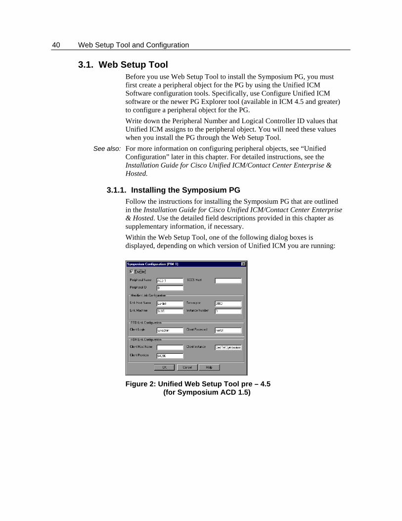
3.1.1. Installing the Symposium PG Follow the instructions for installing the Symposium PG that are outlined in the Installation Guide for Cisco Unified ICM/Contact Center Enterprise & Hosted. Use the detailed field descriptions provided in this chapter as supplementary information, if necessary. Within the Web Setup Tool, one of the following dialog boxes is displayed, depending on which version of Unified ICM you are running:
Figure 2: Unified Web Setup Tool pre – 4.5
(for Symposium ACD 1.5)
Web Setup Tool 41
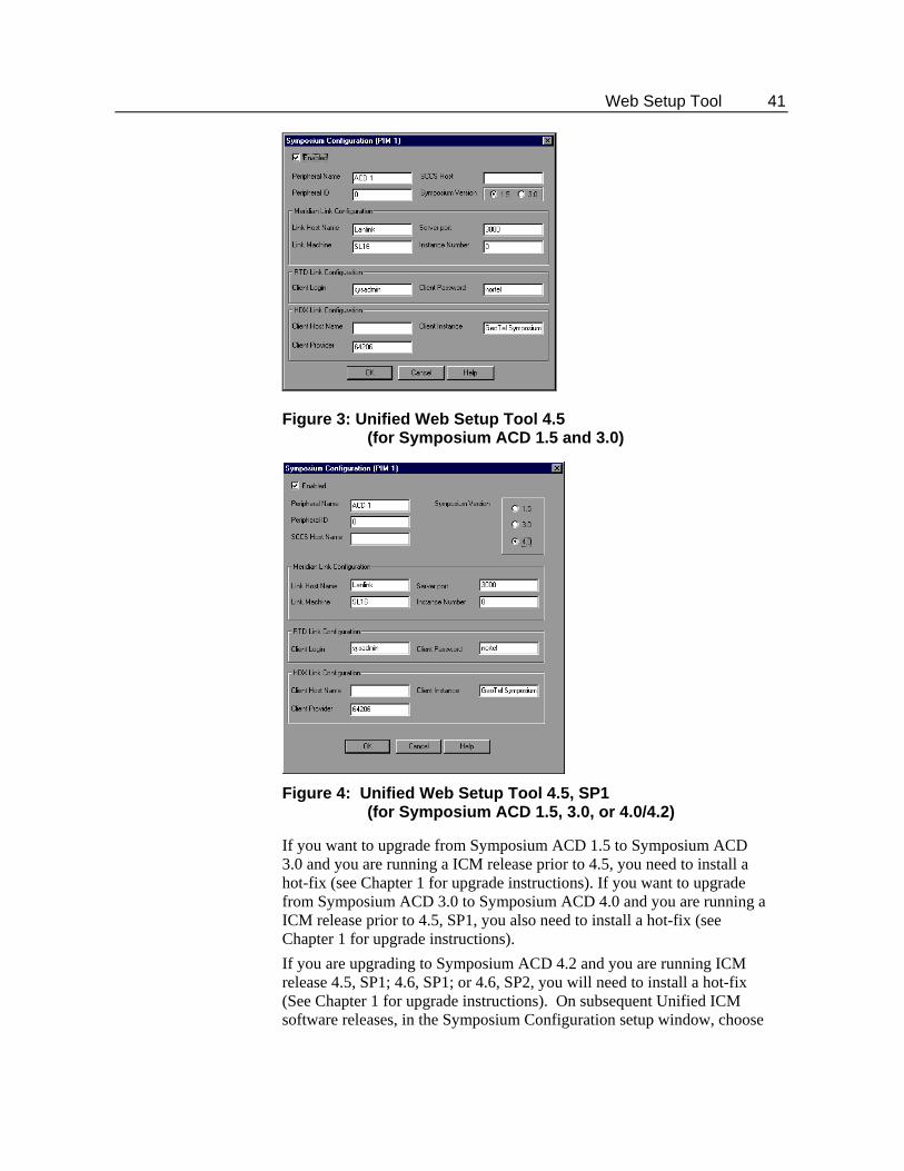
Figure 3: Unified Web Setup Tool 4.5 (for Symposium ACD 1.5 and 3.0)
Figure 4: Unified Web Setup Tool 4.5, SP1
(for Symposium ACD 1.5, 3.0, or 4.0/4.2)
If you want to upgrade from Symposium ACD 1.5 to Symposium ACD 3.0 and you are running a ICM release prior to 4.5, you need to install a hot-fix (see Chapter 1 for upgrade instructions). If you want to upgrade from Symposium ACD 3.0 to Symposium ACD 4.0 and you are running a ICM release prior to 4.5, SP1, you also need to install a hot-fix (see Chapter 1 for upgrade instructions). If you are upgrading to Symposium ACD 4.2 and you are running ICM release 4.5, SP1; 4.6, SP1; or 4.6, SP2, you will need to install a hot-fix (See Chapter 1 for upgrade instructions). On subsequent Unified ICM software releases, in the Symposium Configuration setup window, choose

42 Web Setup Tool and Configuration
4.0 as the Symposium Version for use on either Symposium ACD 4.0 or Symposium ACD 4.2. Make the following settings in the Symposium Configuration screen: Peripheral Name. Set this field to the name by which you identify the
Symposium ACD. Peripheral ID. Set this field to the integer identifier for the peripheral
(ACD) from the Peripheral table of the Unified ICM database. This is the value you obtained when you created a Peripheral object for the Symposium PG in Configure Unified ICM (or the newer PG Explorer tool.)
NCCM server Host. Set the NCCM server Host Name to the IP name or IP address of your NCCM server. Note that if you use a name it must be in the “hosts” file used by the PG.
Note: The PIM becomes active when the three interfaces – Meridian Link Interface (MLink), Host Data Exchange Interface (HDX) and Real Time Data Interface (RTD) register with the PIM. Once it becomes active, the PIM tries to additionally register the Position IDs, Individual Directory Number (IDN) and Controlled DN (DN) using the DNREG command. If the register response (DNREGR) shows that the registrations failed because of bad Resource IDs, it indicates that configuration of position Ids, IDNs or CDNs for which the error was seen on the ACD side do not match with those on the Unified ICM. That is, the configuration numbers on the NCCM server instances should match with those on the Unified ICM.
3.1.2. Meridian Link Configuration Make the following settings in the Meridian Link Configuration section: Link Host Name. Set the Link Host Name to the host name
configured in the link 1 configuration file on the NCCM server system. This defaults to “Lanlink,” and normally you must not change it.
Server port. Set the Server port field to the well-known port used by Meridian Link. The Meridian Link server and Web Setup Tool both default this value to 3000.
Link Machine. Set the Link Machine field to the Meridian 1 Machine name in the link 0 configuration file on the NCCM server system. This defaults to “SL16” and normally you must not change it.
Instance Number. Set the Instance Number field to the customer number on the Meridian 1 for which this PG will route calls. This defaults to 0.

Unified ICM Software Configuration 43
3.1.3. RTD Configuration Make the following settings in the RTD Link Configuration section: Client Login. Set the Client Login field to the user name you have set
up on the NCCM server system for RTD requestors. The default is “sysadmin.”
Client Password. Set the Client Password field to the password for that user. The default is “nortel.”
3.1.4. HDX Configuration Make the following settings in the HDX Link Configuration section: Client Host Name. Set the Client Host Name field to the IP name or
address of the machine on which the Symposium PG will run. Note that if you use a name it must be in the “hosts” file used by the PG. Also note that if you are running a duplexed PG, you will, of course, store different values in this field for side A and side B1
Client Provider ID. Set the Client Provider ID to the ID by which the PG will identify itself to the HDX server. The default for this field is 64206. Normally you must not change this default. You must use this provider id in all of the SEND INFO and SEND REQUEST commands that you put in your NCCM server script. See Chapter 2, “ACD Configuration,” for more information on NCCM server script modifications.
.
Client Instance. Set the Client Instance String field to the string that you want the PG to send to the HDX server as the instance string. The default for this field is “Cisco Symposium PIM.” Normally, you must not change this default.
3.2. Unified ICM Software Configuration In order to properly configure and maintain the Unified ICM database, you need to understand the relationships between the Symposium database objects and the Unified ICM database objects. For example, skill groups correspond to Symposium skill sets, and services correspond to Symposium applications. By understanding the relationships between the Symposium and Unified ICM database objects, it will be easier to keep the Symposium and Unified ICM databases synchronized (that is, up-to-date with each other). This section describes the relationships between the Symposium and the Unified ICM database objects. It also provides information you can use to configure a Symposium PG by using the Unified ICM software configuration tools. Use the information in this section as a supplement to the information contained in the Installation Guide for Cisco Unified ICM/Contact Center Enterprise & Hosted.
1 The IP name or address of the machines running side A and side B respectively
44 Web Setup Tool and Configuration
Note: In earlier releases of Unified ICM, the Configure ICM software tool was used to configure objects in the Unified ICM database. In Unified ICM 4.5 and beyond, a new set of configuration tools are available. In Unified ICM 4.5 and greater, use the Unified ICM Software Configuration Manager to start the appropriate configuration tool (For example, the PG Explorer tool).
3.2.1. Peripheral Configuration In Unified ICM terms, the Symposium ACD itself corresponds to a peripheral. Unified ICM treats all contact center devices (e.g., ACDs, PBXs, IVR systems) as peripherals. Depending on the version of Unified ICM you are running, use either Configure Unified ICM software or the PG Explorer to create a peripheral. Be sure to set the Available Holdoff Delay option to zero. Agent real time data on Symposium will work only if Enable Agent Reporting and therefore Auto Configure are checked.
Note: Symposium PG does not support auto-configuration of agents. Since Agent auto-configuration and Agent reporting are mutually inclusive in the Peripheral configuration screen, the following work around needs to be performed for Agent reporting to work without the call router performing the actual agent configuration. On the callrouters' registry, go to
HKey_Local_Machine/Software/Cisco Systems, Inc./ICM/IRS/RouterA/Router/CurrentVersion/Configuration/AutoConfig
Set the value for AgentEnabled to 0. This implies that the call router will not perform agent auto-configuration even though auto-configuration is turned on. Note that the agents will have to be manually configured even though auto-configuration is turned on.
3.2.2. Peripheral Target Configuration A Unified ICM Peripheral Target is a network target identified by a Network Trunk Group and DNIS that terminates on the Meridian ACD. You must configure a Unified ICM Software Peripheral Target for every DNIS and Network Trunk Group combination through which incoming ACD calls arrive. You must also configure Peripheral Targets for translation routing. Depending on the version of Unified ICM you are running, use either Configure Unified ICM or the Peripheral Target Bulk tools to create a peripheral target.
See also: For more information on Translation Routing and Peripheral Targets, see Chapter 4, “Post-Routing.”

Unified ICM Software Configuration 45
Note that the Symposium ACD supports configurations in which multiple IDC (incoming digit conversion) tables are used to map a single DNIS value to different Symposium CDNs depending on which Symposium Route (Unified ICM software Peripheral Trunk Group) the call arrives. If you use this feature, you must be careful when configuring Network Trunk Groups and Peripheral Targets in Unified ICM. In particular, when you configure a Network Trunk Group you must ensure that all of the Peripheral Trunk Groups in that Network Trunk Group map a given DNIS value to the same Symposium CDN1
For Unified ICM Software Route statistics, the PG attributes calls to Unified ICM Software Routes by looking for a Peripheral Target that matches the Trunk Group and DNIS for the call. If it finds one, it uses the route associated with that Peripheral Target. Otherwise, it looks for any Peripheral Target that matches the DNIS for the call and uses the associated route
. Therefore, if you are using multiple IDC tables you must create a separate Network Trunk Group for each of these tables. You must then create Peripheral Targets to correspond to each of these network trunk groups.
2
3.2.3. Trunk Group Configuration
. Finally, if it finds no matching Peripheral Target it attributes the call to the default route for the peripheral (if one is configured). If there is none, Unified ICM will not gather route or service data for the call.
A Unified ICM Trunk Group is equivalent to a Symposium Route. The Symposium PG requires that you configure the Symposium ACD so that all Symposium Route Numbers are greater than zero. Depending on the version of Unified ICM you are running, use either Configure Unified ICM software or the Network Trunk Group – Trunk Group Explorer tool to configure trunk groups. Configure a Unified ICM software Trunk Group for each Symposium route on which ACD calls arrive. Set the Unified ICM Software Peripheral Number to the Symposium Route Number. Leave the Unified ICM Software Trunk Count at the default value “Use Trunk Data.” Set the Unified ICM Software Trunk Group Extension to the Symposium route access code (ACOD) for the route.
1 Example: Let D be a DNIS value. Suppose network trunk group X consists of
peripheral trunk groups K, L, and M. Then (K, D), (L, D) and (M,D) all refer to the same software peripheral target so it is nonsensical to have K, L and M map D to different Symposium CDNs.
2 You can cause the PG to bypass this step by setting the following registry variable to zero: HKEY_LOCAL_MACHINE/SOFTWARE/Cisco/ICM/PG<XX>/PG/CurrentVersion/OPC/CallControl/MapPeripheralTargetsWithoutTrunkGroup

46 Web Setup Tool and Configuration
3.2.4. Trunk Configuration The Symposium PG does not monitor individual trunks. Therefore, you don’t need to configure individual Unified ICM trunks for Symposium ACDs.
3.2.5. Service Configuration A Unified ICM service is equivalent to a Symposium application. Depending on the version of Unified ICM you are running, use either Configure Unified ICM software or the Service Explorer tool to create a service. You must store the name of the corresponding Symposium application in the Unified ICM software service’s ConfigParam field. Each application must have a unique Unified ICM peripheral number. You may set the value of this field to any value you desire as long as it is unique. The Symposium PG does not use the Extension field. The “Peripheral Service Level Type” setting has no effect since the Symposium PG does not report a peripheral service level (although it does report a Unified ICM software service level).
Important: You must configure Unified ICM software service with the name, “Master_Script.” The ConfigParam field of this service must also be “Master_Script.” You need to configure this service before attempting to start the PIM. If you do not configure the Master_Script service, the PIM will not start and errors will be logged to the PIM log.
Note: On a Symposium PG, ensure that: The services are properly configured with the corresponding routes
and network trunk groups. The peripheral name and the configuration parameter of each service
should be the same as the service name on SCCS. Failure to meet these conditions may result in unexpected behavior of Agent desktops and Call routing.
3.2.6. Skill Group Configuration A Unified ICM skill group is equivalent to a Symposium skill set. Depending on the version of Unified ICM you are running, use either Configure Unified ICM software or the Skill Group Explorer tool in the Unified ICM Software Configuration Manager to configure skill groups. You must store the name of the corresponding Symposium skill set in the Unified ICM skill group’s ConfigParam field. (To avoid confusion, you should also use this name as the name of the Unified ICM skill group, but this is not required.) Each skill group must have a unique Unified ICM Software Peripheral Number. You may set the value of this field to any value you desire as long as it is unique. A Symposium agent is a member of one or more skill sets. For each of these skill sets the agent is assigned a priority from 1 to 48 by the NCCM

Unified ICM Software Configuration 47
server administrator. Use SS as the Symposium skill set and SG as the corresponding Unified ICM software skill group. Unified ICM configuration for SG must contain a sub-group for every priority level at which some agent is a member of SS. For example, if agent A is a member of SS at priority 1 and agent B is a member of SS at priority 5, and no other agents belong to SS, then SG must be configured with subgroups 1 and 5. The Symposium PG does not use the Extension field. The Available Holdoff Delay option should be set to zero.
Note: The skill group name is case sensitive. Ensure that it is the same as the skillset name configured in Symposium.
Important: You must configure a Unified ICM skill group with the name, “Unconfigured_Agents.1” The ConfigParam field of this skill group must also be “Unconfigured_Agents.” The PG will attribute calls to this skill group for any NCCM server agent who does not appear in Unified ICM configuration2
Calls Queued to Agents
. You need to configure this skill group before attempting to start the PIM. If you do not configure the Unconfigured_Agents skill group, the PIM will not start and errors will be logged to the PIM log.
On the Symposium PIM, after a call that was queued to an agent has been answered by the agent, there is about a 15-20 second delay before third-party control is established. Although the voice path happens without any delay, to suppress the delay that happens at any third-party control at the agent-side, add a skill group called Agent_Queued_To on Unified ICM. Ensure that you set the configuration parameter to “Agent Queued To.” Assign this skill group to those agents to whom the calls are queued.
3.2.7. Service Member Mappings No special configuration consideration required.
3.2.8. Agent Configuration A Unified ICM agent is equivalent to a Symposium agent.
1 Even if Unified ICM is integrated with the Automated Administrator for
Symposium (AAS), you need to configure the softeare skill group name as “Unconfigured Agents”. AAS will not configure the “Unconfigured Agents” skill group. For the Symposium PIM to become active, you will need to do the configuration manually.
2 Thus, if you see calls being attributed to this skill group you will know that you have not configured all of your SCCS agents.

48 Web Setup Tool and Configuration
Depending on the version of Unified ICM you are running, use either Configure Unified ICM Software or the Agent Route Explorer tools to configure agents. You must enter every Symposium agent into Unified ICM configuration. Set the Unified ICM Software Agent Peripheral Number to the Symposium Agent ID.
Note 1: The ACD positions used by agents (known to Unified ICM) have to be configured as AST. If an agent moves to another location, the new ACD position also has to be configured as AST and equipped with an AST license.
Note 2: When you delete an agent in Unified ICM, ensure that the agent is permanently deleted. Before deleting, the agent must be logged off from Unified ICM.
3.2.9. Agent State Mapping Table 2 defines the mapping between Symposium agent states and Unified ICM agent states.
Table 2: Symposium-to- Unified ICM Agent State Mapping
Symposium Agent State Unified ICM Software Agent State Not Ready Walkaway Not Ready Emergency Not Ready Not Ready Work Ready Break Work Ready Busy Work Ready Idle Available Call Presented Reserved Active Talking Consultation Talking On Hold Hold On Hold Walkaway Hold
3.2.10. Skill Group Member Mappings You must configure the skill groups to which an agent belongs (and the agent’s priority within each skill group) in Unified ICM skill group member table. Now, with the AAS option (Automated Administrator for Symposium), it is possible for Agent to Skill group mappings to be done automatically. For details, refer to Chapter 7, SEI Lite Interface with Nortel Symposium.
Note: When you change agent to skill group mapping, Unified ICM services need not be restarted. For example, if you re-assign an agent to another skill group or remove an agent from a skill group, it is not required to restart Unified ICM Service."
Unified ICM Software Configuration 49
3.2.11. Translation Routes The Symposium PG supports Translation Routes. See Chapter 4, “Post-Routing” for more information on Translation Routes.
3.2.12. Route Configuration A Unified ICM route is one or more Unified ICM software peripheral targets. A Unified ICM peripheral target is a network target identified by a network trunk group and DNIS that terminates on the Symposium ACD. A peripheral target is equivalent to the combination of DNIS and the (network) trunk group(s) through which incoming ACD calls arrive. Depending on the version of Unified ICM you are running, use either Configure ICM software or the Route Bulk tools to configure routes. No special configuration consideration required.
3.2.13. Routing Client Configuration The Symposium PG supports post-routing. The Symposium PG routing client is active whenever the PG itself is active. Depending on the version of Unified ICM you are running, use either Configure ICM software or the PG Explorer tool to configure a routing client. Enable post-routing for the Symposium PG. You must also configure appropriate Unified ICM dialed numbers and labels for use with post-routing. See Chapter 4, “Post-Routing” for more information. No special configuration consideration required.
3.2.14. Peripheral Monitor Configuration of Symposium CDNs You must configure all of your Symposium CDNs in the Unified ICM Software Peripheral Monitor table. This is required so that the PG can register with Meridian Link to receive events for these CDNs. The Symposium PG will not be able to track calls directed to any Symposium CDN that you have not configured. Depending on the version of Unified ICM you are running, use either Configure ICM software or the PG Explorer tool to configure Symposium CDNs in the Peripheral Monitor table. In addition, you must separately configure each Symposium CDN by creating a Peripheral Monitor table entry whose Type field is “Symposium CDN” and whose “Param String” field is the CDN number. The PG does not currently use the Extension field.
3.2.15. Peripheral Monitor Configuration of Symposium Positions
You must configure all of your ACD positions and their corresponding IDNs in the Unified ICM Software Peripheral Monitor table. This is required so that the PG can register with Meridian Link to receive events for these positions. It also allows the PG to associate IDNs with their

50 Web Setup Tool and Configuration
corresponding position ID values. If you don’t configure all of your positions correctly you may experience difficulty monitoring data and using Enterprise CTI. Depending on the version of Unified ICM you are running, use either Configure ICM software or the PG Explorer to configure ACD positions and IDNs in the Peripheral Monitor table. You configure position IDs and IDNs by creating one or more Peripheral Monitor table entries whose Type field is “Meridian Position” and whose “Param String” field is described in the following paragraph. The PG does not currently use the Extension field. You can use the Param String field to specify a single Symposium position, a range of positions, a single Symposium position and IDN pair, or a range of positions and IDN pairs (see Table 3). In Table 3, a dash indicates a range. A comma indicates that what follows is an IDN specification.
Table 3: Param String Format Examples
Param String Format Example Meaning
Position ID 5201 Indicates a single position “5201” with no associated IDN
Position ID, IDN 5201,4201 Indicates a single position “5201” with associated IDN “4201”
Position ID Range 5201-5299 Indicates a range of positions from “5201” up to “5299.” None of these positions have associated IDN keys.
Position ID Range, IDN Range 5201-5299,4201-4299
Indicates a range of positions from “5201” up to “5299.” Position 5201 is associated with IDN 4201. Position 5202 is associated with IDN 4202, etc.
If your position ID and IDN values are arranged in sequence, you can reduce the number of entries required in the Peripheral Monitor table by specifying ranges of positions. Note that the maximum range the PG allows is 200 positions. If you have ranges that span more than 200 positions, you must enter them as multiple contiguous ranges in separate Peripheral Monitor table entries that span more than 200 positions, you must enter them as multiple contiguous ranges in separate Peripheral Monitor table entries. For proper monitoring of symposium positions and CDNs, please note the following:

Activity Code Configuration 51
Do not add duplicate entries in the Peripheral Monitor table. This leads to the corruption of the table.
You cannot change the Peripheral Monitor type from Meridian position to CDN and vice versa if the configuration parameters remain the same.
3.3. IVR Port Configurations To configure the IVR Port in Unified ICM, add the ACD single line sets/IVR ports in the Peripheral Monitor table just as we would, the position ID and DN of a real agent. That is, set CLS =AGTA, AACD=YES, AST=yes For information regarding adding agents to the Unified ICM Software Peripheral Monitor Table, refer to the section 3.2.15, Peripheral Monitor Configuration of Symposium Positions. By monitoring these IVR ports, using either Meridian MAX/Link or Symposium, you can track all incoming calls from the trunk entry into the PBX, through ACD call modifications (IVR ports) and eventually to Symposium scripts and real agent/skillset queuing.
Note 1: For old MAX/Link platforms, remember to turn on RPRT=yes in ACDDN block and IAPG=yes in the phone overlay in addition to setting CLS =AGTA, AACD=YES, AST=yes.
Note 2: On the side of Unified ICM, Meridian mail ports need not be configured at the Peripheral Monitor table.
3.4. Activity Code Configuration To configure Activity codes in Unified ICM, define the following:
3.4.1. Unified ICM Configuration In the PG Explorer tool, Peripheral tab, define the configuration parameter as /nrc xxx, where xxx is the default activity code.
3.4.2. CTI OS Server Configuration Make the following registry settings in the CTI OS server: [HKEY_LOCAL_MACHINE]\SOFTWARE\Cisco
Systems\CTIOS\Server\Agent\<NotReadyReasonRequired> Specify the value of NotReadyReasonRequired as 1.

52 Web Setup Tool and Configuration
[HKEY_LOCAL_MACHINE]\SOFTWARE\Cisco Systems\CTIOS\Server\Agent\ReasonCodes\NotReady\<Not ready reason code> Specify Not ready reason code as 1.
3.4.3. Meridian PBX and SCCS Configuration You need to configure Activity codes for the following: Agent sets on Meridian SCCS
3.5. Special Considerations in NAM Environments In a Network Applications Manager (NAM) environment, multiple Customer ICM software systems (CICMs) can share the same ACD. If you are a NAM customer and you want to filter out events for ACD agents that are not monitored by your CICM system, then you have to set the LoginUnconfiguredAgents registry key to 1.
To change the LoginUnconfiguredAgents registry key: 1. From the Start menu, click Run. 2. Type regedit to open the registry. 3. Create the following registry data field (REG_DWORD) if it does not
already exist:
SOFTWARE\Cisco Systems, Inc.\...\pgXX\PG\CurrentVersion\PIMS\pimY\ SymposiumData\Dynamic\LoginUnconfiguredAgents
4. Set the value of this field to 1. In non-NAM Unified ICM configurations, this field is set to 0 by default.
3.6. Maintaining Your Configuration It is important to keep your Unified ICM configuration up-to-date when you make NCCM server configuration changes. The following types of NCCM server changes need to be reflected in Unified ICM configuration: Addition of a new application. Addition of a new skill set. Do not forget to configure sub-groups to
reflect all of the priorities at which agents will be members of this skill set.
Addition of a new agent. For every skill set SS to which the agent belongs, you must also add an entry to the skill group member table for the skill group that corresponds to SS. If the agent’s priority, call it X, in a skill set SS is different from the priority in SS of any previously configured agent, you must create a new sub group for X in Unified ICM skill group that corresponds to SS. Note: When the AAS option is in use, new skills and agents will be
added automatically, but the skill group and agent names will

Maintaining Your Configuration 53
be created with defaults, and manual updates within Unified ICM configuration are necessary to give appropriately descriptive names. For details, refer to Chapter 7, SEI Lite Interface with Nortel Symposium.
Addition of a new Symposium route. Changes to Symposium CDNs must be reflected in your Unified ICM
Software Peripheral Monitor table. Changes to ACD positions and IDNs must be reflected in your Unified
ICM Software Peripheral Monitor table.

54 Web Setup Tool and Configuration

55
4. Post-Routing
This chapter describes the changes you must make to Unified ICM configuration, NCCM server configuration, and the NCCM server scripts to be able to post-route calls using the Symposium PG. It also discusses any considerations you should be aware of when using Post-Routing or Translation Routing on the Symposium PG.

56 Post-Routing
4.1. Changes to the NCCM server Configuration This section describes the changes you need to make to your NCCM server configuration to be able to post-route calls.
Important: Commands related to post-routing must be placed in the NCCM server Master Script. If you do not do this, the post-routed call will not be attributed to the correct Unified ICM service (NCCM server application).
4.1.1. Reserve CDNs or DNISs Reserve a set of CDNs or a set of DNISs or both to use for post-routing. Your Master Script must contain lines of the following form: IF (CDN = XXXX .. ZZZZ) THEN
EXECUTE DO_POST_ROUTE END IF
Where XXXX .. ZZZZ is the range of CDNs you have assigned to post routing , or IF (DNIS = XXXX .. ZZZZ) THEN
EXECUTE DO_POST_ROUTE END IF
Where XXXX .. ZZZZ is the range of DNISs you have assigned to post-routing, or a more complicated IF statement if you are using both CDNs and DNISs.
Note: For simplicity, assume for the rest of this section that you are using only CDNs for post-routing.
4.1.2. DO_POST_ROUTE Section of Master Script In the DO_POST_ROUTE section of the Master Script, you must use the following three-way handshake with the Symposium PG to initiate a post-route for a call: SEND REQUEST script command to ask the PG to obtain information
that will allow the NCCM server script to determine the target of the call.
GET RESPONSE script command to obtain a response type and a response value from the PG that the script can then use to continue processing the call.
SEND INFO script command to tell the PG whether or not the NCCM server script timed out while waiting for the response from the PG.
These commands have the following forms:

Changes to the NCCM server Configuration 57
SEND REQUEST <provider_id> pr_req, <dialed_num>, <clid_ani>, <dnis>, <in vars>
Where: <provider_id> identifies the Symposium PG (see Chapter 2 for more
information on <provider_id>. pr_req is a global script variable whose value is the character string
“Post_Route_Request” <dialed_num> is Unified ICM dialed number you have associated
with the post route CDN that led to this SEND REQUEST command (see below for an example)
<clid_ani> is the CLID/ANI associated with the call being post routed <dnis> is the DNIS associated with the call being post routed <in_vars> means zero to five NCCM server script variables separated
by commas. The PG will store the values of these variables into Unified ICM call variables that it will pass to the CallRouter along with the route request. You can then use these call variables in your Unified ICM routing scripts to help control how calls are processed. Which Unified ICM call variables are used is specified by the Unified ICM Call Control Variable map (see the section “Changes to Unified ICM Software Configuration”). Different SEND REQUEST commands may specify different numbers of <in_vars>.
GET RESPONSE <provider_id> <status>, <type>, <value>, <out vars>
Where: <provider_id> identifies the Symposium PG (see Chapter 2 for more
information on <provider_id>. <status> indicates the result of the post route request. A value of zero
indicates that the request was successful. A non-zero value indicates failure. See the example below for a complete list of the failure values and their meaning.
<type> and <value> tell your NCCM server script how to process the call. The values that the PG returns in <type> and <value> are determined by the Unified ICM label that your Unified ICM script returns to the PG in response to the post route request. You must set up your NCCM server and Unified ICM scripts so that the <type> and <value> returned for a given post route request cause the call to be processed in the way that you want. You can make this as simple or as complex as you need. For example, in the sample script fragments below we use CDN and <type> to determine which NCCM server primary script to execute, and use <value> to determine what processing is done within each primary script.
<out vars> means zero to five NCCM server script variables separated by commas. Your Unified ICM scripts can return Unified ICM call variables to the PG as part of the response to the route request. The PG will return the values of these variables in the NCCM

58 Post-Routing
server script variables. You can then use these variables in your NCCM server scripts to help control how calls are processed. Which Unified ICM call variables are returned is specified by the Unified ICM Call Control Variable map (see the section “Changes to the Unified ICM Software Configuration”). All GET RESPONSE commands must specify the same number of <out vars>1
SEND INFO <provider_id> post_route_response_ack, <status>
Where: <provider_id> identifies the Symposium PG (see Chapter 2 for more information on <provider_id>.post_route_response_ack is a global script variable whose value is the character string “Post_Route_Response_Ack.”
.
<status> tells the PG whether or not the NCCM server GET RESPONSE command timed out before it received the post route response from the PG. A value of 0 indicates that it did not time out and that the NCCM server script will use the post route response. A value of 1 indicates that it did time out, and that the response will not be used.
4.1.3. Example of Post-Routing Section in Master Script The post-routing section in the Master Script should look like the example shown below. The script global variables have the following values:
Script Global Variables
Values
pr_req “Post_Route_Request” pr_route_response_ack “Post_Route_Response_Ack” pr_ok 0 pr_sccs_timeout 1 pr_dn_XXXX <the Unified ICM software dialed number you
have associated with CDN XXXX> pr_dn_ZZZZ <the Unified ICM software dialed number you
have associated with CDN ZZZZ> SECTION DO_POST_ROUTE
/* You must set this script call variable to 1 so that you can detect when the GET RESPONSE command below times out. The Symposium PG will never return a status value of 1 */
post_route_status ASSIGNED 1 /* Send a different dialed number to the PG depending on the CDN. The duplicate
1 The SCCS GET RESPONSE command requires that the PG returns exactly as
many values as there are variables specified in the command. Since the PG has no way of determining how many were specified in a given GET RESPONSE command, we require that all commands specify the same number (and this number is known to the PG from the call control variable map)

Changes to the NCCM server Configuration 59
GET RESPONSE messages are necessary because the script compiler will not allow a single GET RESPONSE to be placed at the end of the where clause */
WHERE CDN EQUALS VALUE XXXX:
SEND REQUEST GeoTel_id pr_req, pr_dn_XXXX, clid_ani, dnis_value, <in vars> GET RESPONSE GeoTel_id post_route_status_str, type, value, <out vars>
.
.
.
VALUE ZZZZ: SEND REQUEST GeoTel_id pr_req, pr_dn_ZZZZ, clid_ani, dnis_value, <in vars> GET RESPONSE GeoTel_id post_route_status, type, value, <out vars>
END WHERE
/* If the post route request failed, go log an error, and do something with the call */ IF ( NOT (post_route_status = 0) ) THEN
EXECUTE POST_ROUTE_FAILED END IF
/* If we get here, the post route succeeded, so complete the three way handshake with the Symposium PG as described above */
SEND INFO GeoTel_id post_route_response_ack, pr_ok
/* Act on the information returned by the post route request. Each of the scripts executed below will have a “WHERE response_value EQUALS” command that will process the call based on the response_value */
WHERE CDN EQUALS VALUE XXXX:
WHERE response_type EQUALS VALUE 0: EXECUTE SCRIPT <script for response type 0 and CDN XXXX> . . . VALUE Nxxxx: EXECUTE SCRIPT <script for response type Nxxxx and CDN XXXX> DEFAULT:
LOG "Unknown response type" DISCONNECT
END WHERE . . . VALUE ZZZZ:
WHERE response_type EQUALS VALUE 0: EXECUTE SCRIPT <script for response type 0 and CDN ZZZZ> . . . VALUE Nzzzz: EXECUTE SCRIPT <script for response type Nzzzz and CDN ZZZZ> DEFAULT:
LOG "Unknown response type" DISCONNECT
END WHERE
END WHERE
QUIT

60 Post-Routing
SECTION POST_ROUTE_FAILED
WHERE post_route_status EQUALS
/* A status value of 1 means that the GET RESPONSE script command timed out. So we must inform the Symposium PG that this has happened */
VALUE 1: SEND INFO GeoTel_id post_route_response_ack, pr_sccs_timeout LOG "Route Request Failed: GET RESPONSE timed out"
VALUE 2: LOG "Route Request Failed: ICM timed out"
VALUE 3: LOG "Route Request Failed: PG routing client not running"
VALUE 4: LOG "Route Request Failed: Dialled Number is invalid"
VALUE 5: LOG "Route Request Failed: Bad params - wrong number, type or length"
VALUE 6: LOG "Route Request Failed: Bad ICM post-route label format"
VALUE 7: LOG "Route Request Failed: Too many params after DNIS in SEND REQUEST"
VALUE 8: LOG "Route Request Failed: Request led to circular route"
VALUE 9: LOG "Route Request Failed: Non-numeric or negative translation route label"
VALUE 10: LOG "Route Request Failed" /* For some reason other than those above */
DEFAULT: LOG "Unknown status returned for route request"
END WHERE
The above WHERE command must be followed by script commands that process the call for which the post route failed.
Changes to the Unified ICM Software Configuration 61
4.2. Changes to the Unified ICM Software Configuration You need to make the following changes to your Unified ICM configuration for post-routing.
4.2.1. Labels The label that your Unified ICM scripts must return in response to a post-route request can have one of two forms (where X and Y are integers in the range 0 to 2147483647): X When the PG receives a label of this form from the CallRouter, it
will return a response value of X and a response type of zero to the GET RESPONSE command.
Y.X When the PG receives a label of this form from the CallRouter, it will return a response type of Y and a response value of X to the GET RESPONSE command.
You configure these labels in the normal way using the Unified ICM configuration tools.
4.2.2. Call Control Variable Map Depending on your Unified ICM release, the Call Control Variable Map is configured by using the PG Explorer (4.5 and beyond). The Unified ICM Call Control Variable map for the Symposium PG is a string of the form:
/RREQ <ICM call variable list> /RRES <ICM call variable list>
where <ICM call variable list> is a list of one to five integers in the range 1-10 separated by spaces. One or both of /RREQ and /RRES can be omitted. /RREQ specifies which Unified ICM call variables the <in vars> parameters of the SEND REQUEST should be assigned to. /RRES specifies which Unified ICM call variables should be returned in the <out vars> parameters of the GET RESPONSE.
Note: As mentioned above, every GET RESPONSE must have the same number of <out vars>. For example,
/RREQ 7 2 10
This specifies that the first <in vars> variable in every SEND REQUEST command should be assigned to Unified ICM software call variable 7, the second to Unified ICM call variable 2, and the third to Unified ICM call variable 10. If a SEND REQUEST command specifies more than three <in vars> the other ones will be ignored. If it specifies less, the Unified ICM call variables corresponding to the unspecified NCCM server <in vars> will not be set.
/RRES 8 3
This specifies that Unified ICM call variable 8 will be returned in the first <out vars> variable, Unified ICM software call variable 3 will be returned

62 Post-Routing
in the second <out vars> variable and that all GET RESPONSE commands in your NCCM server scripts will have exactly two <out vars> variables.
Note: Whenever you change the Call Control Variable Map, you need to restart the Symposium PG for the new Call Control Variable Map to take effect.
4.3. Caller Entered Digits Caller-entered digits (CED) obtained using the Symposium “Collect Digits Into” script command can be passed to the PG in a call variable.
4.4. Translation Routing Translation routing is described in the Scripting and Media Routing Guide for Cisco Unified ICM/Contact Center Enterprise & Hosted. A quick review is presented here with emphasis on implementing translation routing with Symposium ACDs. Note that the Translation Route Wizard now automates much of the actual Unified ICM configuration work for translation routes.
4.4.1. Review of How to Configure Translation Routes A translation route is a mechanism for sending a call to a destination ACD X and passing information along with the call. The call information is passed from the CallRouter to the PG connected to X. To send calls to an ACD X through a translation route, you perform the following steps: Configure a translation route T and associate T with the logical
controller for the PG connected to X. Note that each translation route is associated with a single destination peripheral regardless of the routing client that submitted Unified ICM route request.
Decide how many calls can be targeted to T and be “pending” at any given point in time. “Pending” means that the initial route request has been received from the initial routing client but the call has not yet arrived at the target and been matched up by OPC. Once the call arrives at X and is matched up by the PG associated with X it is no longer “pending.” A typical maximum number of expected pending calls would be 10. Allocate 10 unique DNIS values on X to be used only by T.
For each DNIS value D assigned to T, create a route Rd and set the target of Rd to be T. Set the service of Rd to be the “Translation Routing” service for the peripheral.

Translation Routing 63
For each Rd created above, create a single peripheral target PTd with
the DNIS set to D. The network trunk group can be set to any valid trunk group for the peripheral. Each PTd should target its corresponding Rd. Note that the same peripheral targets are used for all routing clients.
For each of the PTd created above, create one label Ldr for each routing client R that will target calls to this translation route.
4.4.2. Symposium Post-Routed Translation Routes Every translation-routed call goes through a post-route at the destination peripheral (to get the label associated with the translation route DNIS). A post-routed translation route goes through two post routes: one at the source peripheral and one at the destination peripheral. If the source and destination peripherals are the same Symposium ACD, the Symposium PG handles the second post route directly without involving the ACD. To make this happen, create one label associated with the Symposium PG routing client for each of the PTd defined above of the form1
Where XXXX is the DNIS stored in PTd. When the PG receives such a label as a response to a post route request, it issues a second post route request using DNIS XXXX, gets back a new label, and returns the response_type and response_value specified by that label to the GET RESPONSE command that initiated the original post route request.
:
^XXXX
1 Note that in the case being discussed, the translation route T is associated with
the Symposium ACD that is both the source and destination of the translation route.

64 Post-Routing
65
5. ACD-Specific Interpretation of Unified ICM Software Data
This chapter discusses principles to keep in mind when attempting to compare Unified ICM database reporting elements to the reporting elements of the Symposium ACD.

66 ACD-Specific Interpretation of Unified ICM Software Data
5.1. Method of Attributing Calls to Services The Symposium PG attributes a call to the service corresponding to the application associated with the first primary script to which the call interflows. It will not change the associated application if the call interflows to another primary script. This is the same as what the NCCM server does. See “Interflowed’ in Chapter 2, “ACD Configuration,” for more information. If a call is answered and then transferred to a Symposium CDN, the second call is tracked as an independent call to the destination service by the Symposium PG.
5.2. Method of Attributing Calls to Skill Groups The Symposium PG attributes answered calls to Unified ICM skill group that corresponds to the NCCM server skill set in which the agent answered the call. Due to limitations in the Nortel Symposium interfaces, the PG usually will not know which skill group to attribute the call to until several seconds after the call is answered.
5.3. Calculation of Handle Time The Unified ICM defines handle time for a call as “the time an agent spends talking on a call and performing related after-call work.” The Symposium ACD allows an agent to go into “Not Ready” state to perform after-call work, but does not directly support the concept of attributing after-call work time to an individual call. Since an agent can activate the “Not Ready” key at any time, simply dividing the total “Not Ready” time for an agent by the number of calls answered will not yield an accurate average per-call after-call work time. Within the limitations described in the following paragraphs, the Symposium PG attributes “Not Ready” time to individual calls if the agent enters the NCCM server “Not Ready” state directly after handling a call and before the NCCM server -assigned break time has elapsed. If the agent enters the “Not Ready” state in this interval the handle time for the call (and for the service) will include the time spent in the “Not Ready” state and the time spent in the “Break” state prior to entering the “Not Ready” state. Note that all time in the “Not Ready” state is also accounted for in the Unified ICM skill group wrap-up time statistics. The preceding paragraph is an oversimplification. Due to limitations in the Nortel Symposium interfaces, the PG does not know how much break time (if any) Symposium has assigned to a given agent, nor does it know whether an agent has entered the “Break” state until several seconds after the call hangs up. Therefore, when a call hangs up, the PG assumes that the associated agent has entered the “Break” state, and waits for an RTD message that will tell it what the agent’s NCCM server state really is. If
Handling of ROUTE CALL Script Command 67
the agent enters the “Not Ready” state in this interval1
5.4. Handling of ROUTE CALL Script Command
, the PG will assign all of the time since the call hung up to the handle time for the call, even if the agent had actually entered the NCCM server “Idle” state after the call hung up and had subsequently entered the “Not Ready” state. Also if the agent answers another call in the above mentioned interval, the PG will attribute all of the time before the new call is answered, to the handle time for the previous call even if the agent was actually in the “Idle” state between the two calls.
Two cases can occur when the processing of a NCCM server call leads to the execution of a ROUTE CALL XXXX script command: XXXX is a number that sends the call off-switch (e.g., a number
that includes a trunk access code). In this case, the call is no longer under the control of the NCCM server software. When this occurs the PG receives no more information about the call and stops monitoring it. The call is removed from real time calls in queue statistics. The disposition in the termination call detail record is set to “Redirected.” The call is reflected in historical services records as an “overflow out” call. If the call is routed to another CDN or ACD DN on the same switch (e.g., a trunk call that winds up going to a number on the same switch) the PG will track this as a new call.
XXXX is a number that is local to the switch (e.g., the number of a local ACD DN). In this case, the Symposium PG will continue to track the call as long as you have specified the “local” parameter in the HDX Routed command. (See “Routed” in Chapter 2, “ACD Configuration,” for more information.)
5.5. Handling of ROUTE CALL CONTROLLED Script Command
Two cases can occur when the processing of a NCCM server call leads to the execution of a ROUTE CALL XXXX CONTROLLED script command: XXXX is a number that sends the call off-switch (e. g. a number
that includes a trunk access code). In this case, the call may no longer be under the control of the NCCM server software. When the PG receives the SEND INFO command associated with the ROUTE CALL CONTROLLED it has no way of determining whether the ROUTE CALL CONTROLLED will terminate NCCM server processing, or whether control will return to the NCCM server script. Therefore, the PG waits for a period of time to see if it
1 The interval between when the call hangs up and when the PG receives an RTD
message telling it what SCCS state the agent entered after the call hung up.
68 ACD-Specific Interpretation of Unified ICM Software Data
will receive a Controlled_Returned SEND INFO script command indicating that control has returned to the NCCM server script (see “Controlled_Returned” in Chapter 2, “ACD Configuration,” for more information). If it does not receive such a command during the period, it assumes the call is no longer under the control of the NCCM server software and behaves as in “Handling of ROUTE CALL Script Command,” earlier in this chapter.
XXXX is a number that is local to the switch (e.g., the number of a local ACD DN). In this case, the Symposium PG will continue to track the call as long as you have specified the “local” parameter in the HDX Routed command. (See “Routed” in Chapter 2, “ACD Configuration” for more information.)
5.6. Handling of QUEUE TO NACD Script Command When the processing of a call includes the execution of a QUEUE TO NACD XXXX script command1
Answered by the local NCCM server system, either because it was also queued to skill sets and/or agents and one of those agents became available before any agent associated with XXXX, or because the day table associated with the XXXX contained a local ACD queue YYYY, and an agent became available on YYYY.
, several different things can subsequently happen to the call. The call could be:
In this case, the Symposium PG will continue to track the call (see below).
Dequeued from the NACD queue, in which case the call continues to be processed by the local NCCM server script. In this case, the Symposium PG will continue to track the call (see below).
Answered by a remote system. In this case, the call is no longer under the control of the NCCM server software. When this occurs the PG receives no more information about the call and stops monitoring it. The call is removed from real time calls in queue statistics. The disposition in the termination call detail record is set to “Redirected.” The call is reflected in historical services records as an “overflow out” call (see below). If the call is routed to another CDN or ACD DN on the same switch the PG will track this as a new call.
The problem is that the Symposium PG has no way of knowing, a priori, which of the cases above will happen. Also, it will never know for sure
1 As mentioned earlier, you should avoid using the QUEUE TO NACD script
command

Handling of GIVE BUSY Script Command 69
that the last case has occurred, because NCCM server does not send it any message when the call is answered by a remote site. So, when the PG receives an HDX NACD_Queued message telling it that a QUEUE TO NACD command has been executed for a call, it sets a timer T whose duration in seconds is specified by the registry entry (relative to HKEY_LOCAL_MACHINE/SOFTWARE):
Cisco Systems, Inc./ICM/PG<xx>/PG/CurrentVersion/PIMS/pim1/SymposiumData/ Dynamic/QueueToNACDWaitTimeout
Each time it receives an HDX NACD_Ping message, it reschedules T. If T goes off, the PG assumes that the call has been answered by a remote site and behaves as described in the third case above. Otherwise, the PG continues to track the call as described in the first two cases above. (See “NACD_Ping” in Chapter 2, “ACD Configuration,” for more information.)
5.7. Handling of GIVE BUSY Script Command When the processing of an NCCM server call leads to the execution of a GIVE BUSY script command, the call is no longer under the control of the NCCM server software. When this occurs the PG receives no more information about the call and stops monitoring it. The call is removed from real time calls in queue statistics. The disposition in the termination call detail record is set to “Forced Busy.” The call is reflected in historical services records as a “terminated other” call.
5.8. Handling of GIVE BUSY CONTROLLED Script Command
When the processing of a NCCM server call leads to the execution of a GIVE BUSY CONTROLLED script command, the call may no longer be under the control of the NCCM server software. When the PG receives the SEND INFO command associated with the GIVE BUSY CONTROLLED it has no way of determining whether the GIVE BUSY CONTROLLED will terminate NCCM server processing, or whether control will return to the NCCM server script. Therefore, the PG waits for a period of time to see if it will receive a Controlled_Returned SEND INFO script command indicating that control has returned to the NCCM server script (see “Controlled_Returned” in Chapter 2, “ACD Configuration”). If it does not receive such a command during the period, it assumes the call is no longer under the control of the NCCM server software and behaves as in “Handling of GIVE BUSY Script Command,” earlier in this chapter.
5.9. Handling of GIVE OVERFLOW Script Command When the processing of an NCCM server call leads to the execution of a GIVE OVERFLOW script command, the call is no longer under the control of the NCCM server software. When this occurs the PG receives no more information about the call and stops monitoring it. The call is removed
70 ACD-Specific Interpretation of Unified ICM Software Data
from real time calls in queue statistics. The disposition in the termination call detail record is set to “Disconnect Drop No Answer.” The call is reflected in historical service records as a “terminated other” call.
5.10. Handling of GIVE OVERFLOW CONTROLLED Script Command
When the processing of a NCCM server call leads to the execution of a GIVE OVERFLOW CONTROLLED script command, the call may no longer be under the control of the NCCM server software. When the PG receives the SEND INFO command associated with the GIVE OVERFLOW CONTROLLED it has no way of determining whether the GIVE OVERFLOW CONTROLLED will terminate NCCM server processing, or whether control will return to the NCCM server script. Therefore, the PG waits for a period of time to see if it will receive a Controlled_Returned SEND INFO script command indicating that control has returned to the NCCM server script (see “Controlled_Returned” in Chapter 2, “ACD Configuration”). If it does not receive such a command during the period, it assumes the call is no longer under the control of the NCCM server software and behaves as in “Handling of QUEUE OVERFLOW Script Command,” earlier in this chapter.
5.11. Handling of DISCONNECT Script Command When the processing of a NCCM server call leads to the execution of a DISCONNECT script command, the call is no longer under the control of the NCCM server software. When this occurs the PG receives no more information about the call and stops monitoring it. The call is removed from real time calls in queue statistics. The disposition in the termination call detail record is set to “Disconnect Drop No Answer.” The call is reflected in historical service records as a “terminated other” call.
5.12. Handling of Trunk Group Statistics Due to limitations in the Nortel interfaces, the Symposium PG does not support Unified ICM Trunk Group real-time data elements and Trunk Group half-hour data elements.
5.13. Enhancements to the Dialed Number List Tool The Dialer Number List Tool is enhanced to accommodate one million dialed numbers. This is achieved by using the Customer Definition filter and Routing Client filters. Additionally, the tool is redesigned to load the labels when a label change is made "only". These enhancements increase tool performance and reduce user interface time.

71
6. Media Blender Configuration for Nortel Symposium
This chapter discusses what you need to know and do to configure the Cisco Media Blender for use with the Nortel Symposium ACD. Note: From ICM 8.0 onwards, Cisco Media Blender is not supported with Nortel Symposium ACD.

72 Media Blender Configuration for Nortel Symposium
Media Blender Integration with Unified ICM Media Blender software is integrated with Unified ICM and Unified ICM routes calls through the Media Blender by means of the Cisco CTI Driver. The Media Blender provides support for Unified CCE and legacy ACDs, including the Nortel Symposium, using the Cisco CTI driver. A new firewall gateway service allows Unified Web Interaction Manager (Unified WIM), which resides outside a firewall, to communicate with the Unified ICM Peripheral Gateway(s) that reside inside the firewall. An example of a FirewallGatewayService.properties file is shown later in this document.
6.1. Key Property Files You need to edit or check the following Media Blender property files:
• Blender.Properties • ACD.ciscocti.properties • Collaboration.properties (copied from Unified WIM) • Phantoms.properties • <Connection_CMB>.properties (copied from Unified WIM) • Service.FWGW.properties • FirewallGateway.properties • Resource.properties
The following two of these files are connection property files that you need to copy from the collaboration Unified WIM system to the CMB (Cisco Media Blender) system: Collaboration.properties <Connection_CMB>.properties The appropriate directory paths to copy from and to are listed below under the associated property file names.
Note: The user names the <Connection_CMB>.properties file. By doing so, the user can create a meaningful name for the site; for example, a name containing the names of the machines that are linked.
6.1.1. Blender.Properties In the CiscoMB\Servlet\Properties\Blender\blender.properties file, configure the following two properties as follows. This means that you uncomment the two lines setting these properties in the property file: medium1=ACD.ciscocti.properties
Required. The Medium1 property identifies the property file for the ACD medium used with the Media Blender. Note that this property file must reside in the same directory as blender.properties. The file used for the Nortel Symposium is ACD.ciscocti.properties.
medium2=Collaboration.properties

Key Property Files 73
Required. The Medium2 property identifies the property file for the call queuing medium and should be listed after medium1. Note that this property file must reside in the same directory as blender.properties. The file gets created by the Unified WIM and needs to be copied to the Cisco Media Blender directory. See the separate section on the Collaboration.properties file for further information.
Verbose=8 Optional. Add the verbose=8 entry to the property file if you want to enable more test related information in the blender logs
Service1=Service.jwgw.properties Required. Uncomment Service1 to enable Firewall Gateway Service.
6.1.2. ACD.ciscocti.properties In the CiscoMB\Servlet\Properties\Blender\ACD.ciscocti.properties file, edit or add the following property settings: peripheral.type=Symposium
Required. Uncomment the line with the Symposium peripheral type. peripheral.id=<insert here the peripheral ID, as defined in the Unified
ICM PG Explorer> Required. Example: peripheral.id=5007
peripheral.hostname=<insert here the host name for CTI Server for this peripheral> Required. This is the peripheral name or the agent PG’s IP address to the peripheral. Example: peripheral.hostname=m2pg10a
peripheral.hostport=<insert here the host port of CTI Server for this peripheral> Required. This can be obtained from the process window title bar of the CTI Server connected to the agent PG. This is the primary port connection between the media blender and the peripheral Example: peripheral.hostport=42027
peripheral.hostname2= This is the name of the backup peripheral that connections to the media blender Optional. Example: peripheral.hostname2=m2pg10b
74 Media Blender Configuration for Nortel Symposium
peripheral.hostport2= This is the backup port connection between the media blender and the peripheral. Optional. Example: peripheral.hostport2=43027
peripheral.username=<insert here the peripheral user name> Required. Example: peripheral.username=cmb-m2cmb3
peripheral.password= (if there is no password, you can leave this blank) Optional. Example: peripheral.password=
peripheral.comment= /*Enter optional comments here*/ Optional. Example: peripheral.comment=/* m2cmb3 is attached to a Symposium ACD via M2PG8a */
phantompool=phantoms.properties Required if you are using any phantom strategies. The name of the file that contains the list of phantoms. This file must be used if you are using phantom strategies.
autoanswer=true Optional. Set this to true so that the Media Blender answers Media Blender-controlled incoming calls for the agent. There is no need for the agent to answer the agent’s phone.
readyaftersignon=true Required.. Set this to true to place an agent in the ready state after auto-login.
Ignoreareacode=<insert here the area code and, if you want, the exchange that you want to have ignored> Optional. However, it must be set if you want the area code or part of the phone number ignored. This is used for internal testing with the next property so that calls can be routed by their last digits only. Example: Ignoreareacode=978322
Permittedphonenumlength=<insert here the phone digits> Optional. However, this must be used if you are using the Ignorearecode property. This specifies the number of digits, beginning with the last one that is used to route a number. Do not use commas to separate number length options. Use spaces to separate the numbers.

Key Property Files 75
The following example says that the system will route calls by 10, 5, or 4 digits. Example: Permittedphonenumlength=10 5 4
6.1.3. Collaboration.properties This properties file is created by the Unified WIM. You need to manually copy the Collaboration.properties file from the Unified WIM system to the CMB (Cisco Media Blender) system. The directory paths to copy from and to are as follows:
From: <CCS_dir>\servlet\properties\cmb\connection_name\blender\collaboration.properties
To: <Cisco_MB_directory>\servlet\properties\blender\collaboration.properties
6.1.4. Phantoms.properties In the CiscoMB\Servlet\Properties\Blender\phantoms.properties file, add or edit the ID list of all your phantom agents and their types. You can use the agent’s ID or the agent’s extension number as an ID. D=DIGITAL is the only valid type. Use the format ID_number=D. Required. Example: 5584=D 5583=D
6.1.5. <Connection_CMB>.properties This properties file is created by the Unified WIM but named by you when configuring the Unified WIM for the media blender. You might put in the name the names of the two machines it connects. You need to manually copy the Connection_CMB.properties file from the Unified WIM system to the Cisco Media Blender system.
The directory paths to copy from and to are: From: <CCS_dir>\servlet\properties\cmb\conn_name\<Connection_CMB>.properties
To: <CMB_dir>\servlet\properties\<Connection_CMB>.properties
76 Media Blender Configuration for Nortel Symposium
An Example <Connection_CMB>.properties File
## ---------------------------------------##
## RMI Properties ## ## -------------------------------------------##
conn6_cmb.rmi.Name=conn6_cmb
conn6_cmb.rmi.RemoteHost=m2ccs6
conn6_cmb.rmi.RemoteRegistryPort=1099
conn6_cmb.rmi.RemotePassword={enc:2}Zm9v
conn6_cmb.rmi.LocalRegistryPort=1099
conn6_cmb.rmi.LocalPassword={enc:2}Zm9v
conn6_cmb.rmi.Description=
conn6_cmb.rmi.DisableAutoConnect=false
conn6_cmb.rmi.PollingHeartbeatCount=2
conn6_cmb.rmi.ConnectionAttempts=1
Note: The HOSTS file in the system32/drivers/etc directory should contain the host and IP address mappings for all the machines involved with RMI Firewall Gateway connections.
Verify and or add entries as necessary on the Unified WIM and CMB machines.
6.1.6. Service.FWGW.properties In the CiscoMB\Servlet\Properties\Blender\service.FWGW.properties file, set autostart to true for the Firewall Gateway service. Required. Example: autostart=true
6.1.7. FirewallGateway.properties The FirewallGateway.properties file is stored in the CiscoMB\Servlet\Properties directory. The following is an example FirewallGateway.properties file. The property values in bold are examples. You need to replace the bold text with the correct values for your system’s configuration.
Note: If there is only a primary CTI Server host, either comment-out the backup server or use the same information as the primary. If you do not do this, the cmb.log file will fill an 1800 K file, 3 files per minute!
################################
# FirewallGateway.properties #
################################
#----------------------------------------------
#- Agent Reporting and Management (ARM) section
#----------------------------------------------
Key Property Files 77
# Set the value of this property to false if there is no ARM #connection
FirewallGateway.ARM.active=true
# Edit <Connection_CMB> in the following properties
FirewallGateway.ARM.LocalService=conn6_cmb_CMB_ARM
FirewallGateway.ARM.RemoteService=conn6_cmb_CCS_ARM
FirewallGateway.ARM.RMIProps=conn6_cmb.properties
# Edit <PrimaryHostname> and <BackupHostname> in the following #properties
FirewallGateway.ARM.plugin.param.primaryCtiServerHostname=m1pg4a (or IP address)
FirewallGateway.ARM.plugin.param.backupCtiServerHostname=m1pg4b (or IP address) * use the same info as for the primary connection OR just comment the line out (#)
# Edit <PrimaryServerPort> and <BackupServerPort> in the #following properties
FirewallGateway.ARM.plugin.param.primaryCtiServerPort=42027
FirewallGateway.ARM.plugin.param.backupCtiServerPort=43027
# Do not edit the following properties
FirewallGateway.ARM.ACKType=ACK_ALL
FirewallGateway.ARM.ACKMaxDelay=5000
FirewallGateway.ARM.flushOnDisconnect=false
FirewallGateway.ARM.plugin.messageSpecsFile=CCSGED188ARMDefs.xml
FirewallGateway.ARM.plugin.class=com.cisco.msg.plugin.socket.CTIServerPlugin
FirewallGateway.ARM.plugin.param.topicCreator=com.cisco.ics.ccs.bus.ICMCcsTopicCreator
FirewallGateway.ARM.plugin.param.waitForApplication=10
#--------------------------------------
#- Media Routing (MR) section - Primary
#--------------------------------------
# Set the value of this property to false if there is no MR connection
FirewallGateway.MR_Primary.active=true
# Edit <Connection_CMB> in the following properties
FirewallGateway.MR_Primary.LocalService=conn6_cmb_CMB_MRI
FirewallGateway.MR_Primary.RemoteService=conn6_cmb_CCS_MRI
FirewallGateway.MR_Primary.RMIProps=conn6_cmb.properties
# Edit <Port> in the following property
FirewallGateway.MR_Primary.plugin.param.port=2000
# Do not edit the following properties

78 Media Blender Configuration for Nortel Symposium
FirewallGateway.MR_Primary.ACKType=ACK_ALL
FirewallGateway.MR_Primary.ACKMaxDelay=5000
FirewallGateway.MR_Primary.flushOnDisconnect=false
FirewallGateway.MR_Primary.plugin.messageSpecsFile=MR.xml
FirewallGateway.MR_Primary.plugin.class=com.cisco.msg.plugin.socket.MediaRoutingPIMPlugin
FirewallGateway.MR_Primary.plugin.param.waitForApplication=10
#-------------------------------------
#- Media Routing (MR) section - Backup
#-------------------------------------
# Set the value of this property to false if there is no backup MR connection
FirewallGateway.MR_Backup.active=true
# If the preceding property line is false, you can disregard the following Edit lines
# and comment out the next 3 lines.
# Edit <Connection_CMB> in the following properties
FirewallGateway.MR_Backup.LocalService=conn6_cmb_CMB_MRI
FirewallGateway.MR_Backup.RemoteService=conn6_cmb_CCS_MRI
FirewallGateway.MR_Backup.RMIProps=conn6_cmb.properties
# Edit <Port> in the following property
FirewallGateway.MR_Backup.plugin.param.port=2000
# Do not edit the following properties
FirewallGateway.MR_Backup.ACKType=ACK_ALL
FirewallGateway.MR_Backup.ACKMaxDelay=5000
FirewallGateway.MR_Backup.flushOnDisconnect=false
FirewallGateway.MR_Backup.plugin.messageSpecsFile=MR.xml
FirewallGateway.MR_Backup.plugin.class=com.cisco.msg.plugin.socket.MediaRoutingPIMPlugin
FirewallGateway.MR_Backup.plugin.param.waitForApplication=10
6.1.8. Resource.Properties The Resource.properties file is located in the C:\Program Files\New Atlanta\ServletExec ISAPI\ServletExec Data\default directory. This file allows you to add a user name by which you can log into Media Blender.

Key Property Files 79
Example Resource.Properties File
Note: Before doing the following, you need to create the user “qaadmin” through Microsoft Windows (Go to Programs → Administrative Tools → Computer Management. When the Computer Management window displays, select System Tools, then Local Users and Groups. Right click on the Users directory to add a new user. Make the new user a member of “Administrator.”) Then restart the Blender IIS Administration and WWW services.
The following example adds the user qaadmin to login as Blender Administrator: Blender.groups= Blender.users=Administrator, qaadmin BlenderNew.groups= BlenderNew.users=Administrator, qaadmin wlPageCompile.groups= wlPageCompile.users=Administrator, qaadmin

80 Media Blender Configuration for Nortel Symposium
6.2. Voice and Chat CTI Call Strategies The available CTI strategies are designed to provide appropriate callback in different configurations and for different call strategies.
6.2.1. Voice Call Strategies The following two CTI strategies can be used with voice calls.
PhantomWaitRelease
Media Blender dials into a queue using one of the phantom lines. Once the agent answers, the phantom line is placed on hold while Media Blender places an outbound call to the caller using the agent's second line. Once the caller answers the phone, the phantom line is released.
PhantomWaitNoRelease
This strategy is similar to PhantomWaitRelease except the phantom line stays connected to the agent for the length of the call. This provides more detailed agent handle time reporting from the ACD, but it requires a larger pool of phantom lines. One phantom line is allowed for each caller.
6.2.2. Chat Session Strategies The following three CTI strategies can be used for chat sessions. Note that when a chat session is active, the agent’s phone is unavailable.
PhantomNoCallRelease
Use this strategy if you want to provide chat sessions and if your ACD is configured to place agents in a busy state as soon as their phones disconnect. This strategy connects to an agent but releases the phantom line immediately. The agent is placed in a busy state, allowing the agent and caller to engage in a text chat session uninterrupted.
PhantomNoCallNoRelease
Use this strategy if you want to provide chat sessions and if your ACD does not support the automatic busying out of agents. Media Blender uses the phantom line to select the agent; however, the phantom does not release the agent's phone until the session is complete. This provides more accurate reporting, but requires a larger pool of phantom lines.
PhantomNoCallNoHold
This strategy is similar to the PhantomNoCallNoRelease strategy except the call from the phantom line to the agent is not placed in the hold state. Rather it remains in the talking state. For reporting purposes, this strategy has the ACD report that the agent is talking while using chat.
6.2.3. CTI Strategies for Nortel Symposium Nortel Symposium is supported with Unified ICM CTI Server for Unified ICM integration on Windows 2000.

Configuring the Symposium Switch 81
The following table lists the CTI strategies that can be used for the Nortel Symposium supported by the basic Media Blender configuration: PhantomWaitRelease
PhantomWaitNoRelease
PhantomNoCallRelease
PhantomNoCallNoRelease
PhantomNoCallNoHold
6.2.4. Routing Address and Routing Numbers When a callback request comes in, Media Blender retrieves the routing address from the callback form and matches it to the ACD routing number. The ACD then routes the request to the appropriate agent. The Routing Address is a code embedded in the Blender Callback HTML form used by the caller. The Routing Address is set in a hidden field, RoutingAddr, on the Callback form. Cisco provides a sample callback form (/<CCS dir>/pub/html/forms/callFormACD.html) that the Unified WIM administrator can use to create the callback form for your site. The Routing number is equal to a value unique to the CDN routing number logic on the Nortel Symposium. See a switch administrator to obtain appropriate routing numbers. In most cases, it will be necessary to create a new routing number, such as CDN, on the switch for use with the Unified WIM application. Refer to the Cisco Media Blender Switch Administration Guide and consult a switch administrator for more information.
6.3. Configuring the Symposium Switch Configure your agents, skill groups, services, and any phantom phones. Skill group: Create the skill group in Unified ICM Configuration Manager. When doing so, you must also create the Symposium Position on the Peripheral Monitoring tab within the Unified ICM Configuration Manager’s PG Explorer by adding the agent ids and instrument numbers. For example: 6571 – 6574;6581 – 6584
An Example Skill Group Configuration on a Nortel Symposium TYPE ACD OBTN NO RAGT 4 CUST 0 RAO NO DURT 30 ACDN 5054 CWTH 1 RSND 4 MWC NO NCWL NO FCTH 20 DSAC NO BYTH 0 CROS 100 MAXP 20 OVTH 2047 SDNB NO TOFT NONE BSCW NO HPO NO ISAP YES OCN NO VSID 1 OVDN AACO NO IFDN

82 Media Blender Configuration for Nortel Symposium
RGAI NO OVBU LNK LNK LNK LNK
ACAA NO EMRT FRRT MURT SRRT RTPC NO NRRT HOML YES FROA NO RDNA NO FNCF NO ACNT FORC NO NRAC NO RTQT 0 DAL NO SPCP YES RPRT YES
Service: Configure the service when you configure the PG. Phantom phones: Use any available phones. Do not just log in.
Example Configuration Settings on the Nortel Symposium ACD
Symposium link: merlink Server port: 3000 Link Host Name: Lanlink Link Machine Name: SL16 Blender Application name: m2cmb3 CCS Application name: m2ccs3
Example Configuration Settings on the MEI (MAX Event Interface) Server
PG: m2pg8a MRPG: m2pg1a PIM 6 Peripheral ID: 5037 MeiServer: geolabntrgra port: 44444
6.4. Testing the Symposium Switch
6.4.1. Create a Unified WIM Agent for the Nortel Symposium Switch
1. Log into the Cisco Unified WIM Administration & Data Server.
2. Click Agents > Create. Then click Next.
3. Enter the agent’s login name (first and last name) and password. Then enter the voice agent’s ID and click Next.
4. Leave ICM software Routing as the default and click Apply.

Testing the Symposium Switch 83
5. If you select the Terminal ID, the physical phone extension for agent creation, then the agent will automatically be logged into the same terminal all the time and cannot switch terminals by using the “ACD Blended Login” form in Unified WIM.
Note: - You have to use the instrument ID of the phones instead of
the phone extension. For example: Agent LoginID: 5571 Terminal: 5571
- If you want the agents to be able to select the "allow agent to change terminals" option when they log in, then you cannot enter a terminal ID. If you do not select this option, you are required to enter a terminal ID.
See the About Settings for Blended Collaboration Agents sub section in the Collaboration Agents section in the Cisco Collaboration Server Administrator Guide for more information.
6. Enter the Symposium ACD Password if required. Otherwise, leave it blank for any agent ID.
7. Enter the assigned skill group number. For example: #5560 Note: When you place a call, use the extension #
(for example: 5582, 5581, 4501) and not the instrument #.
6.4.2. Log in a Blended Collaboration Agent on a Symposium Phone
1. Access the //CCS-Host-Server/
2. Access the ‘ACD Blended Login, Change Terminals’ link
3. Enter the agent’s login name and password. For example: Symposium5571, webline.
4. Enter the Terminal ID in the Terminal # field. For example: 5571, 5572, 5573 or 5574.
5. Click LOGIN.
The Cisco Unified WIM Single Session Chat user interface should show the agent as logged into the Blended Collaboration user interface. Note: You can make an agent not ready by pressing the Not Ready
button.

84 Media Blender Configuration for Nortel Symposium
6.4.3. Make a Blended Collaboration Caller Request to a Symposium Agent/Phone
1. Agent: Access the //CCS-Host-Server/
2. Agent: Access the ‘Blended ACD caller.’ To do so, enter the Caller’s First and Last name.
3. Agent: Enter the Caller’s Phone Number: For example: 978 322-4501 or 978 322-4502. Always use the extension number of the Symposium phone for the caller’s phone number.
4. Agent: Enter the Script Number for making a blended collaboration call: For example: Symposium_DN, where DN is the dialed number label name used in the Unified ICM Configuration Manager.
The agent’s phone will light at the instrument button (the bottom right button). This means the phantom phone is being used. The Caller’s phone will ring and light at the Extension button.
5. Caller: Presses the Caller’s Extension button.
The agent and caller will now be connected through the phones AND in an active session through Collaboration.
6.4.4. Log In an Agent on a Nortel Symposium Phone 1. Press the Skill Group/Instrument button. This is the bottom right
button.
2. Enter the agent’s extension number.
3. Press the pound (#) button 3 times to login.
Note: The agent’s extension is usually 10 or sometimes 1000 greater than the instrument number. So if the button shows '5000/5203,' then the agent’s extension number is 5213 or 6203. You can also login an agent using the skill group to which the agent is assigned.
To Logout: press the Make Ready button twice.
6.4.5. Place a call on a Nortel Symposium Phone 1. Calling Agent: Presses Extension button.
2. Calling Agent: Enters the receiving agent's 4-digit extension number. The receiving agent's phone rings.
3. Receiving Agent: Presses the Extension button on receiving agent’s phone.

Testing the Symposium Switch 85
The agents are now talking. Note: Press the Release button to hang up the call. (The Release
button is the upper left, small red button.)
6.4.6. Transfer a Call on a Nortel Symposium Phone 1. Execute LOGIN and place a call (see the preceding “Place a
call…” steps).
2. Calling Agent: Presses the Transfer button.
3. Calling Agent: Enters the agent's 4-digit extension to whom the call is to be transferred. Receiving agent's phone rings.
4. Receiving Agent: Presses the receiving agent’s Extension button.
5. Calling Agent: Presses the Transfer button again.
Receiving agent and caller are now talking. Note: The originating agent is no longer connected with the call. The
call is transferred either BLIND or by the receiving agent answering the call.
6.4.7. Place a Conference Call on a Nortel Symposium Phone 1. Execute LOGIN and place a call (see the preceding “Place a
call…” steps).
2. Calling Agent: Presses the Conference button (It is the button just above the Extension button.).
3. Calling Agent: Enters the agent's 4-digit extension to whom the call is to be conferenced. The Receiving agent's phone rings.
4. Receiving Agent: Presses the receiving agent’s Extension button.
5. Calling Agent: Presses the Conference button again.
Both agents and caller are now talking. Note: Both agents must press the red RLS (Release) button to hang
up the conference call.
6.4.8. Making an Agent Not Ready You can make an agent not ready by pressing the Busy button twice.

86 Media Blender Configuration for Nortel Symposium

87
7. SEI Lite Interface with Nortel Symposium
This chapter gives an overview about how the Nortel Symposium administration interfaces with the NCCM server Symposium Event Interface (SEI Lite) interface using the Automated Administrator for Symposium (AAS) software. Please be informed that the AAS is an optional package with the Nortel Symposium PG1
See also: For specific information on installation and troubleshooting information, see the Cisco Unified ICM Automated Administrator for Symposium (AAS) Installation and Troubleshooting Guide.
.
1 Please be informed that there is no SEI version of the Symposium PG. The same
version of the Symposium PG functions in both AAS and non-AAS environments.

88 SEI Lite Interface with Nortel Symposium
7.1. Supporting Agent Re-skilling at the Unified ICM Software
The Symposium PIM can be modified to update the dynamic change in the agent or skill group mappings at the Unified ICM database. The change of agent skill group mapping or association can be done at the Agent Explorer/Skill Group Explorer. Alternatively, it can be made in the Symposium configuration when AAS is in use. For details about AAS, refer to Section 7.2. Once the agent skill group association is modified dynamically at the Unified ICM database through the Agent/Skill Group Explorers, the information will flow from Logger to Router to OPC to PIM, where PIM will update the agent state at OPC.
Note: The agent re-skilling feature is supported only on the Unified ICM. This feature provided by the SEI Lite Interface with NCCM server (formerly known as Symposium Call Center Server) is supported only in ICM releases 5.0(0) SR10, 6.0(0) SR3 and beyond.
7.2. Using the SEI Lite Feature with AAS The Automated Administrator for Symposium (AAS)1
1 For Unified ICM support to AAS, the Administration and Data Servers must be
installed to support the use of the ConAPI interface. The Administration and Data Servers can either be installed as a co-resident with the PG, or installed on a separate machine.
is middleware software within the PG service that converts the NCCM server Nortel Symposium Event Interface (SEI) messages into Unified ICM software ConAPI messages. The AAS component within the PG service is started and stopped along with the other PG components. AAS synchronizes the administrative changes made on the NCCM server with the Unified ICM database, thereby eliminating the need for a system administrator to administer changes twice. Without the AAS component, the system administrator has to administer changes once in the Nortel Administration, and once in the Unified ICM administration. All additions, deletions and updates to agents and their skill sets made using Nortel Symposium administration are dynamically made to the Unified ICM database. The AAS synchronizes with the Symposium at startup to make sure that Unified ICM is up-to-date. No attempt is made to synchronize changes in the other direction. (That is, changes to agents’ skill sets made on Unified ICM are not automatically reflected on the Nortel System).
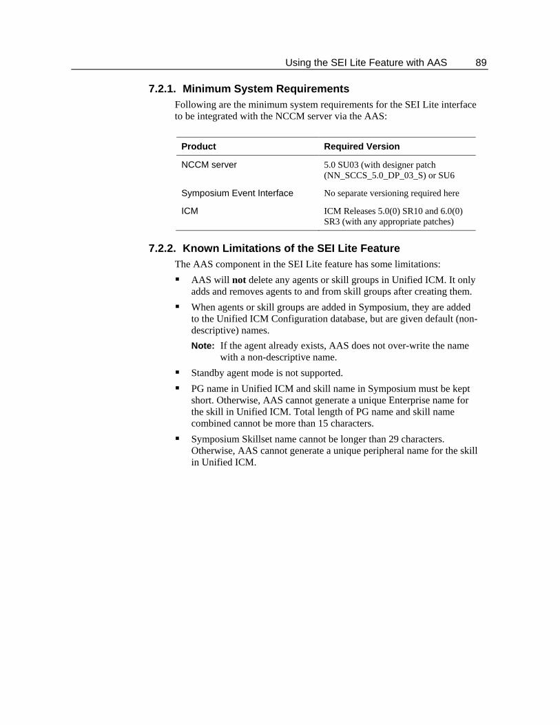
Using the SEI Lite Feature with AAS 89
7.2.1. Minimum System Requirements Following are the minimum system requirements for the SEI Lite interface to be integrated with the NCCM server via the AAS:
Product Required Version
NCCM server 5.0 SU03 (with designer patch (NN_SCCS_5.0_DP_03_S) or SU6
Symposium Event Interface No separate versioning required here
ICM ICM Releases 5.0(0) SR10 and 6.0(0) SR3 (with any appropriate patches)
7.2.2. Known Limitations of the SEI Lite Feature The AAS component in the SEI Lite feature has some limitations: AAS will not delete any agents or skill groups in Unified ICM. It only
adds and removes agents to and from skill groups after creating them. When agents or skill groups are added in Symposium, they are added
to the Unified ICM Configuration database, but are given default (non-descriptive) names. Note: If the agent already exists, AAS does not over-write the name
with a non-descriptive name. Standby agent mode is not supported. PG name in Unified ICM and skill name in Symposium must be kept
short. Otherwise, AAS cannot generate a unique Enterprise name for the skill in Unified ICM. Total length of PG name and skill name combined cannot be more than 15 characters.
Symposium Skillset name cannot be longer than 29 characters. Otherwise, AAS cannot generate a unique peripheral name for the skill in Unified ICM.

90 SEI Lite Interface with Nortel Symposium

Index-1
Index
A AAS, 88 ACD
configuration, 29 ACD script modifications, 30 ACD scripts, 19 ACD.ciscocti.properties, 75 Active, 50 agent re-skilling, 88 Agent states, 50 Application, 20 Arrived command, 31 Associate Telephone (AST), 38 Available, 50
B Blender.Properties, 74 Break, 50 Busy, 50
C Call Control Variable Map, 61 Call Presented, 50 Caller-entered digits (CED), 62 Cisco Media Blender
configuring for Symposium, 73 Client Host Name field, 45 Client Instance field, 45 Client Login field, 45 Client Password field, 45 Client Provider ID field, 45 Collaboration.properties, 76 Consultation, 50 Controlled DN (CDN), 19 Controlled_Returned command,
37
D Dequeued command, 34 Dequeued_Agent command, 34 Disconnect command, 38 DO_POST_ROUTE, 56 Duplexed PG, 18
E Emergency, 50 Enqueued command, 33 Enqueued_Agent command, 34 Enqueued_MLA command, 33 Enqueued_MLA_Begin
command, 33 Enqueued_MLA_End command,
33 Enqueued_MLA_Next
command, 33
F FirewallGateway.properties, 78
G GIVE RINGBACK command,
31 Give_Busy command, 37 Gove_Overflow command, 37
H Handle time, 66 Hardware and software
requirements, 22 Hardware configuration, 18 HDX, 25 HDX Link Configuration, 45
2 Index-2
Hold, 50 Host Data Exchange (HDX), 22 Host Data Exchange Interface
(HDX), 17 Host Enhanced Routing, 22
I ICM configuration, 45
maintaining, 54 ICM configuration tools, 41 ICM features, 23 ICM Setup tool, 41 ICM software configuration, 45 Idle, 50 In-Bound Call Management, 22 Instance Number field, 44 Interflowed command, 32
L Labels, 61 Link Host Name field, 44 Link Machine field, 44
M Master script, 19, 56
post-routing example, 58 Master Script example, 31 Meridian Link Configuration, 44 Meridian Link Interface
(MLink), 17, 22 Multiple application support, 23
N NACD_Dequeued command, 36 NACD_Ping command, 35 NACD_Queued, 34 nbnmsrvc.exe, 25 nicoms_1.exe, 25 NCCM server, 18 NCCM server Host field, 44 NCCM server master script, 56 Not Ready, 50, 66 Not Ready Walkaway, 50
O On Hold, 50 On Hold Walkaway, 50
Out-Bound Call Management, 22
P Param String field, 52 Periheral Monitor table, 51 Peripheral, 46 Peripheral ID field, 44 Peripheral Monitor table, 52 Peripheral Name field, 44 Peripheral service level
reporting, 23 Peripheral target, 46 PG platform requirements, 25 Phantoms.properties, 77 Post-Routing, 55 Primary script, 19 Property Files, 74
Q QUEUE TO NACD command,
23, 32, 34
R Real Time Data Interface (RTD),
17 Real-Time Data (RTD), 22 Reporting data, 66 Reserved, 50 Resource.Properties, 80 Route Number, 38 Routed command, 36 Routing client, 51 RTD, 25 RTD Link Configuration, 45
S Script
modifications, 30 scripts
ACD, 19 Secondary scripts, 19 SEI Lite, 87 Server Port field, 44 Service members, 49 Service.FWGW.properties, 78 Services, 48 Simplexed PG, 18

Index-3
Skill group mapping, 50 Skill groups, 48 Support for multiple
applications, 23 Swap Feature, 20 Symposium ACD capacity, 40 Symposium Call Center Server
(SCCS), 18 Symposium Event Interface, 87 Symposium Switch
testing, 83
T Talking, 50
Translation Route Wizard, 62 Translation routing, 62 Translation Routing, 55 Trunk Group data, 23 Trunk groups, 47
U Upgrade procedures, 25, 26
W Work Ready, 50