Cisco Nexus 1000V for VMware vSphere High … Nexus 1000V for VMware vSphere High Availability and...
46
Cisco Nexus 1000V for VMware vSphere High Availability and Redundancy Configuration Guide, Release 5.x First Published: August 22, 2014 Last Modified: September 18, 2015 Americas Headquarters Cisco Systems, Inc. 170 West Tasman Drive San Jose, CA 95134-1706 USA http://www.cisco.com Tel: 408 526-4000 800 553-NETS (6387) Fax: 408 527-0883
Transcript of Cisco Nexus 1000V for VMware vSphere High … Nexus 1000V for VMware vSphere High Availability and...
Cisco Nexus 1000V for VMware vSphere High Availability andRedundancy Configuration Guide, Release 5.xFirst Published: August 22, 2014
Last Modified: September 18, 2015
Americas HeadquartersCisco Systems, Inc.170 West Tasman DriveSan Jose, CA 95134-1706USAhttp://www.cisco.comTel: 408 526-4000 800 553-NETS (6387)Fax: 408 527-0883
THE SPECIFICATIONS AND INFORMATION REGARDING THE PRODUCTS IN THIS MANUAL ARE SUBJECT TO CHANGE WITHOUT NOTICE. ALL STATEMENTS,INFORMATION, AND RECOMMENDATIONS IN THIS MANUAL ARE BELIEVED TO BE ACCURATE BUT ARE PRESENTED WITHOUT WARRANTY OF ANY KIND,EXPRESS OR IMPLIED. USERS MUST TAKE FULL RESPONSIBILITY FOR THEIR APPLICATION OF ANY PRODUCTS.
THE SOFTWARE LICENSE AND LIMITEDWARRANTY FOR THE ACCOMPANYING PRODUCT ARE SET FORTH IN THE INFORMATION PACKET THAT SHIPPED WITHTHE PRODUCT AND ARE INCORPORATED HEREIN BY THIS REFERENCE. IF YOU ARE UNABLE TO LOCATE THE SOFTWARE LICENSE OR LIMITED WARRANTY,CONTACT YOUR CISCO REPRESENTATIVE FOR A COPY.
The Cisco implementation of TCP header compression is an adaptation of a program developed by the University of California, Berkeley (UCB) as part of UCB's public domain versionof the UNIX operating system. All rights reserved. Copyright © 1981, Regents of the University of California.
NOTWITHSTANDINGANYOTHERWARRANTYHEREIN, ALL DOCUMENT FILES AND SOFTWARE OF THESE SUPPLIERS ARE PROVIDED “AS IS"WITH ALL FAULTS.CISCO AND THE ABOVE-NAMED SUPPLIERS DISCLAIM ALL WARRANTIES, EXPRESSED OR IMPLIED, INCLUDING, WITHOUT LIMITATION, THOSE OFMERCHANTABILITY, FITNESS FORA PARTICULAR PURPOSEANDNONINFRINGEMENTORARISING FROMACOURSEOFDEALING, USAGE, OR TRADE PRACTICE.
IN NO EVENT SHALL CISCO OR ITS SUPPLIERS BE LIABLE FOR ANY INDIRECT, SPECIAL, CONSEQUENTIAL, OR INCIDENTAL DAMAGES, INCLUDING, WITHOUTLIMITATION, LOST PROFITS OR LOSS OR DAMAGE TO DATA ARISING OUT OF THE USE OR INABILITY TO USE THIS MANUAL, EVEN IF CISCO OR ITS SUPPLIERSHAVE BEEN ADVISED OF THE POSSIBILITY OF SUCH DAMAGES.
Any Internet Protocol (IP) addresses and phone numbers used in this document are not intended to be actual addresses and phone numbers. Any examples, command display output, networktopology diagrams, and other figures included in the document are shown for illustrative purposes only. Any use of actual IP addresses or phone numbers in illustrative content is unintentionaland coincidental.
Cisco and the Cisco logo are trademarks or registered trademarks of Cisco and/or its affiliates in the U.S. and other countries. To view a list of Cisco trademarks, go to this URL: http://www.cisco.com/go/trademarks. Third-party trademarks mentioned are the property of their respective owners. The use of the word partner does not imply a partnershiprelationship between Cisco and any other company. (1110R)
© 2009-2015 Cisco Systems, Inc. All rights reserved.
C O N T E N T S
C H A P T E R 1 New and Changed Information 1
New and Changed Information for High Availability 1
C H A P T E R 2 Overview 3
Information About High Availability 3
System Components 4
Service-Level High Availability 5
Isolation of Processes 5
Process Restartability 6
System-Level High Availability 6
Network-Level High Availability 6
VSM-to-VSM Heartbeats 6
Control and Management Interface Redundancy 7
Partial Communication 8
Loss of Communication 8
VSM-VEM Communication Loss 8
One-Way Communication 9
Split-Brain Resolution 9
Checking the Accounting Logs and the Redundancy Traces 10
VSM Role Collision Detection 10
Displaying the Role Collision 11
Enhancements for Domain ID Collision 12
Displaying Domain ID Collision 12
Recommended Reading 13
C H A P T E R 3 Understanding Service-Level High Availability 15
Information About Cisco NX-OS Service Restarts 15
Restartability Infrastructure 15
Cisco Nexus 1000V for VMware vSphere High Availability and Redundancy Configuration Guide, Release 5.x iii

System Manager 16
Persistent Storage Service 16
Message and Transaction Service 16
High Availability Policies 16
Process Restartability 17
Stateful Restarts 18
Stateless Restarts 18
Switchovers 18
Restarts on Standby Supervisor Services 19
Restarts on Switching Module Services 19
Troubleshooting Restarts 19
MIBs 19
RFCs 20
Technical Assistance 20
C H A P T E R 4 Configuring System-Level High Availability 21
Information About System-Level High Availability 22
Information About Single and Dual Supervisor Roles 22
HA Supervisor Roles 22
Dual Supervisor Active and Standby Redundancy States 23
Dual Supervisor Synchronization 23
Information About VSM Restarts and Switchovers 24
Restarts on Standalone VSMs 24
Restarts on Dual VSMs 24
Switchovers on Dual VSMs 24
Switchover Characteristics 24
Automatic Switchovers 25
Manual Switchovers 25
Guidelines and Limitations 25
Configuring System-Level High Availability 25
Changing the VSM Role 25
Configuring a Switchover 27
Guidelines and Limitations for Configuring a Switchover 27
Verifying that a System is Ready for a Switchover 27
Manually Switching the Active VSM to Standby 28
Cisco Nexus 1000V for VMware vSphere High Availability and Redundancy Configuration Guide, Release 5.xiv
Contents

Configuring the VSM-to-VSM Heartbeat Interval 29
Adding a Second VSM to a Standalone System 30
Adding a Second VSM to a Standalone System 30
Changing the Standalone VSM to a Primary VSM 30
Verifying the Change to a Dual VSM System 31
Replacing the Secondary VSM in a Dual VSM System 32
Replacing the Primary VSM in a Dual VSM System 32
Changing the Domain ID in a Dual VSM System 33
Changing the Domain ID in a Dual VSM System for VSMs Hosted on Cisco Nexus 1010 35
Disabling Domain ID Collision 37
Verifying the HA Status 38
Related Documents 39
Standards 39
MIBs 39
RFCs 40
Technical Assistance 40
Feature History for System-Level High Availability 40
Cisco Nexus 1000V for VMware vSphere High Availability and Redundancy Configuration Guide, Release 5.x v
Contents

Cisco Nexus 1000V for VMware vSphere High Availability and Redundancy Configuration Guide, Release 5.xvi
Contents

C H A P T E R 1New and Changed Information
This chapter lists new and changed content in this document by software release.
• New and Changed Information for High Availability, page 1
New and Changed Information for High AvailabilityThis section lists new and changed content in this document by software release.
To find additional information about new features or command changes, see the Cisco Nexus 1000V ReleaseNotes and Cisco Nexus 1000V Command Reference.
Table 1: New and Changed Features for the Cisco Nexus 1000V High Availability Configuration Guide
Where DocumentedChanged in ReleaseDescriptionFeature
Enhancements forDomain ID Collision, onpage 12
5.2(1)SV3(1.1)The high availabilityfunctionality on CiscoNexus 1000V is enhancedto detect domain IDcollisions and keep highavailability (HA) intact.Any rogue VSM with thesame domain ID will notaffect the HA.
Enhancements forDomain ID Collision
Cisco Nexus 1000V for VMware vSphere High Availability and Redundancy Configuration Guide, Release 5.x 1

Cisco Nexus 1000V for VMware vSphere High Availability and Redundancy Configuration Guide, Release 5.x2
New and Changed InformationNew and Changed Information for High Availability

C H A P T E R 2Overview
This chapter contains the following sections:
• Information About High Availability, page 3
• System Components, page 4
• Service-Level High Availability, page 5
• System-Level High Availability, page 6
• Network-Level High Availability, page 6
• VSM-to-VSM Heartbeats, page 6
• Split-Brain Resolution, page 9
• Checking the Accounting Logs and the Redundancy Traces, page 10
• VSM Role Collision Detection, page 10
• Displaying the Role Collision, page 11
• Enhancements for Domain ID Collision, page 12
• Displaying Domain ID Collision, page 12
• Recommended Reading, page 13
Information About High AvailabilityThe purpose of high availability (HA) is to limit the impact of failures—both hardware and software—withina system. The Cisco NX-OS operating system is designed for high availability at the network, system, andservice levels.
The following Cisco NX-OS features minimize or prevent traffic disruption in the event of a failure:
• Redundancy—Redundancy at every aspect of the software architecture.
• Isolation of processes—Isolation between software components to prevent a failure within one processdisrupting other processes.
Cisco Nexus 1000V for VMware vSphere High Availability and Redundancy Configuration Guide, Release 5.x 3

• Restartability—Most system functions and services are isolated so that they can be restarted independentlyafter a failure while other services continue to run. In addition, most system services can perform statefulrestarts, which allow the service to resume operations transparently to other services.
• Supervisor stateful switchover—Active/standby dual supervisor configuration. The state and configurationremain constantly synchronized between two Virtual SupervisorModules (VSMs) to provide a seamlessand stateful switchover in the event of a VSM failure.
Starting with Release 4.2(1)SV2(1.1), the high availability functionality is enhanced to support the split activeand standby Cisco Nexus 1000V Virtual Supervisor Modules (VSMs) across two data centers to implementthe cross-DC clusters and the VM mobility while ensuring high availability.
System ComponentsThe Cisco Nexus 1000V system is made up of the following:
• One or two VSMs that run within Virtual Machines (VMs).
• Virtual EthernetModules (VEMs) that run within virtualization servers. VEMs are represented as moduleswithin the VSM.
• A remote management component. VMware vCenter Server.
Cisco Nexus 1000V for VMware vSphere High Availability and Redundancy Configuration Guide, Release 5.x4
OverviewSystem Components

The following figure shows the HA components and the communication links between them.
Figure 1: HA Components and Communication Links
Service-Level High Availability
Isolation of ProcessesThe Cisco NX-OS software has independent processes, known as services, that perform a function or set offunctions for a subsystem or feature set. Each service and service instance runs as an independent, protectedprocess. This way of operating provides a highly fault-tolerant software infrastructure and fault isolationbetween services. A failure in a service instance does not affect any other services that are running at thattime. Additionally, each instance of a service can run as an independent process, which means that twoinstances of a routing protocol can run as separate processes.
Cisco Nexus 1000V for VMware vSphere High Availability and Redundancy Configuration Guide, Release 5.x 5
OverviewService-Level High Availability

Process RestartabilityCisco NX-OS processes run in a protected memory space independently of each other and the kernel. Thisprocess isolation provides fault containment and enables rapid restarts. Process restartability ensures thatprocess-level failures do not cause system-level failures. In addition, most services can perform stateful restarts.These stateful restarts allow a service that experiences a failure to be restarted and to resume operationstransparently to other services within the platform and to neighboring devices within the network.
System-Level High AvailabilityThe Cisco Nexus 1000V supports redundant VSM virtual machines—a primary and a secondary—runningas an HA pair. Dual VSMs operate in an active/standby capacity in which only one of the VSMs is active atany given time, while the other acts as a standby backup. The VSMs are configured as either primary orsecondary as a part of the Cisco Nexus 1000V installation.
The state and configuration remain constantly synchronized between the two VSMs to provide a statefulswitchover if the active VSM fails.
Network-Level High AvailabilityThe Cisco Nexus 1000V high availability at the network level includes port channels and the Link AggregationControl Protocol (LACP). A port channel bundles physical links into a channel group to create a single logicallink that provides the aggregate bandwidth of up to eight physical links. If a member port within a port channelfails, the traffic previously carried over the failed link switches to the remaining member ports within the portchannel.
Additionally, LACP allows you to configure up to 16 interfaces into a port channel. A maximum of eightinterfaces can be active, and a maximum of eight interfaces can be placed in a standby state.
VSM-to-VSM HeartbeatsThe primary and secondary VSMs use a VSM-to-VSM heartbeat to do the following within their domain:
• Broadcast their presence
• Detect the presence of another VSM
• Negotiate active and standby redundancy states
When a VSM first boots up, it broadcasts discovery frames to the domain to detect the presence of anotherVSM. If no other VSM is found, the booting VSM becomes active. If another VSM is found to be active, thebooting VSM becomes the standby VSM. If another VSM is found to be initializing (for example, during asystem reload), the primary VSM has priority over the secondary to become the active VSM.
Cisco Nexus 1000V for VMware vSphere High Availability and Redundancy Configuration Guide, Release 5.x6
OverviewProcess Restartability

Starting with Release 5.2(1)SV3(1.1) and later releases, the VSM validates the source MAC address ofthe high availability (HA) packets that it receives on control and management interfaces. During initialcontact, the VSM learns the peer VSMMAC addresses and stores them in a permanent location. Only theHA packets that are learned from the VSM are accepted.
Note
After the initial contact and role negotiation, the active and standby VSMs unicast the following in heartbeatmessages:
• Redundancy state
• Control flags requesting action by the other VSM
The following intervals apply when sending heartbeat messages.
DescriptionInterval
Interval at which heartbeat requests are sent.Inter-VSM heartbeat
Default: 1 second
At the active VSM
• Half of the inter VSM maximum heartbeat loss is the interval after whichmissed heartbeats indicate degraded communication on the control interfaceso that heartbeats are also sent on the management interface. This is knownas degraded mode.
• Inter-VSMmaximum heartbeat loss is the interval after which communicationover the control interface with the standby VSM is considered down.
At the standby VSM
• Inter-VSM maximum heartbeat loss is the interval after if no communicationis received from the active VSM (over the control or management interface),the standby VSM interprets it as an active VSM failure and it becomes active.
Inter-VSM maximumheartbeat loss
Range : 6-30 seconds
Default : 15 seconds
The standby VSM is reset by the active VSM when the active VSM is no longerable to synchronize with it, which means that the interval varies depending on howlong the active VSM can buffer the data to be synchronized when the communicationis interrupted.
Varies
Control and Management Interface RedundancyThe VSM communicates with the peer VSM over layer 2 only on the control and management interfaces. Ifthe active VSM does not receive a heartbeat response over the control interface for a period of half of theinter-VSMmaximum heartbeat loss interval (eight heartbeats by default), communication is seen as degradedand the VSM begins sending requests over the management interface in addition to the control interface. Inthis case, the management interface provides redundancy by preventing both VSMs from becoming active.This process is called an active-active or split-brain situation.
Cisco Nexus 1000V for VMware vSphere High Availability and Redundancy Configuration Guide, Release 5.x 7
OverviewControl and Management Interface Redundancy
The communication is not fully redundant, however, because the management interface only handlesheartbeat requests and responses.
Note
AIPC and the synchronization of data between VSMs is done through the control interface only.
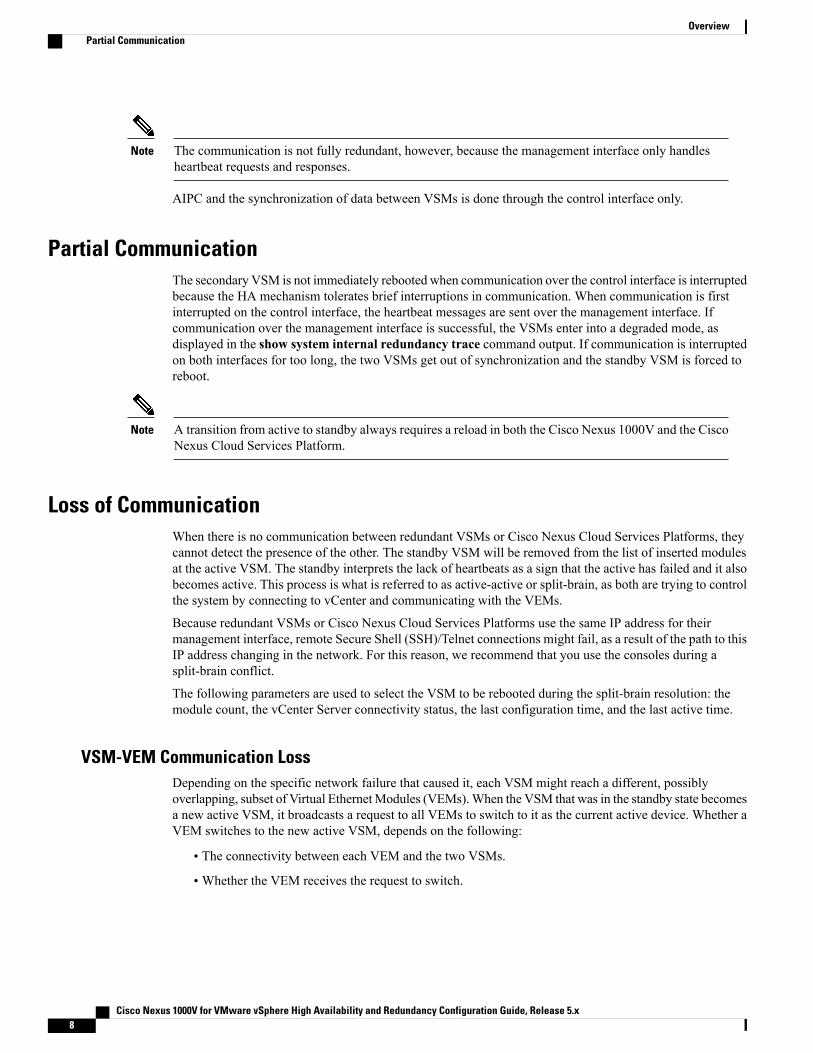
Partial CommunicationThe secondary VSM is not immediately rebooted when communication over the control interface is interruptedbecause the HA mechanism tolerates brief interruptions in communication. When communication is firstinterrupted on the control interface, the heartbeat messages are sent over the management interface. Ifcommunication over the management interface is successful, the VSMs enter into a degraded mode, asdisplayed in the show system internal redundancy trace command output. If communication is interruptedon both interfaces for too long, the two VSMs get out of synchronization and the standby VSM is forced toreboot.
A transition from active to standby always requires a reload in both the Cisco Nexus 1000V and the CiscoNexus Cloud Services Platform.
Note
Loss of CommunicationWhen there is no communication between redundant VSMs or Cisco Nexus Cloud Services Platforms, theycannot detect the presence of the other. The standby VSM will be removed from the list of inserted modulesat the active VSM. The standby interprets the lack of heartbeats as a sign that the active has failed and it alsobecomes active. This process is what is referred to as active-active or split-brain, as both are trying to controlthe system by connecting to vCenter and communicating with the VEMs.
Because redundant VSMs or Cisco Nexus Cloud Services Platforms use the same IP address for theirmanagement interface, remote Secure Shell (SSH)/Telnet connections might fail, as a result of the path to thisIP address changing in the network. For this reason, we recommend that you use the consoles during asplit-brain conflict.
The following parameters are used to select the VSM to be rebooted during the split-brain resolution: themodule count, the vCenter Server connectivity status, the last configuration time, and the last active time.
VSM-VEM Communication LossDepending on the specific network failure that caused it, each VSM might reach a different, possiblyoverlapping, subset of Virtual EthernetModules (VEMs).When the VSM that was in the standby state becomesa new active VSM, it broadcasts a request to all VEMs to switch to it as the current active device. Whether aVEM switches to the new active VSM, depends on the following:
• The connectivity between each VEM and the two VSMs.
• Whether the VEM receives the request to switch.
Cisco Nexus 1000V for VMware vSphere High Availability and Redundancy Configuration Guide, Release 5.x8
OverviewPartial Communication

A VEM remains attached to the original active VSM even if it receives heartbeats from the new active VSM.However, if the VEM also receives a request to switch from the new active VSM, it detaches from the originalactive VSM and attaches to the new VSM.
If a VEM loses connectivity to the original active device and only receives heartbeats from the new one, itignores those heartbeats until it goes into headless mode, which occurs approximately 15 seconds after it stopsreceiving heartbeats from the original, active VSM. At that point, the VEM attaches to the new active VSMif it has connectivity to it.
If a VEM loses the connection to its VSM, VMotionsthat particular VEM is blocked. The VEM showsvCenter Server a degraded (yellow) status.
Note
One-Way CommunicationIf a network communication failure occurs where the standby VSM receives heartbeat requests but the activeVSM does not receive a response, the following occurs:
• The active VSM declares that the standby VSM is not present.
• The standby VSM remains in a standby state and continues receiving heartbeats from the active VSM.
In this scenario, the redundancy state is inconsistent (show system redundancy state) and the two VSMslose synchronization. When two-way communication is resumed, the standby VSM replies to the active VSMand asks to be reset.
If a one-way communication failure occurs in the active to standby direction, it is equivalent to a total lossof communication because a standby VSM sends heartbeats only in response to active VSM requests.
Note
Split-Brain ResolutionWhen the connectivity between two Virtual SupervisorModules (VSMs) is broken, this loss of communicationcan cause both VSMs to take the active role. This condition is called active-active or split-brain condition.When the communication is restored between the VSMs, both VSMs exchange information to decide whichone would have a lesser impact on the system, if rebooted.
Both primary and secondary VSMs process the same data to select the VSM (primary or secondary) that needsto be rebooted. When the selected VSM is rebooted and attaches itself back to the system, high availabilityis back to normal. The VSM uses the following parameters in order of precedence to select the VSM to berebooted during the split-brain resolution:
1 Module count—The number of modules that are attached to the VSM.
2 vCenter status— Status of the connection between the VSM and vCenter.
3 Last configuration time—The time when the last configuration is done on the VSM.
4 Last standby-active switch—The time when the VSM last switched from the standby state to the activestate. (The VSM with a longer active time gets higher priority.)
Cisco Nexus 1000V for VMware vSphere High Availability and Redundancy Configuration Guide, Release 5.x 9
OverviewOne-Way Communication
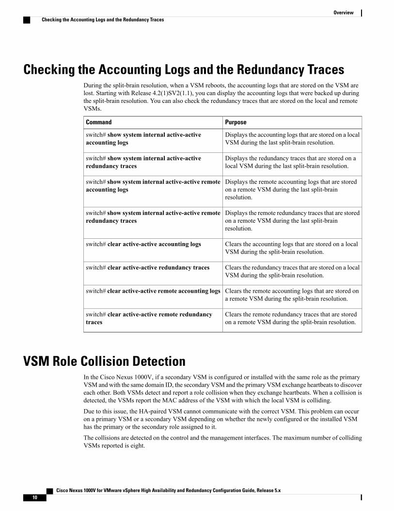
Checking the Accounting Logs and the Redundancy TracesDuring the split-brain resolution, when a VSM reboots, the accounting logs that are stored on the VSM arelost. Starting with Release 4.2(1)SV2(1.1), you can display the accounting logs that were backed up duringthe split-brain resolution. You can also check the redundancy traces that are stored on the local and remoteVSMs.
PurposeCommand
Displays the accounting logs that are stored on a localVSM during the last split-brain resolution.
switch# show system internal active-activeaccounting logs
Displays the redundancy traces that are stored on alocal VSM during the last split-brain resolution.
switch# show system internal active-activeredundancy traces
Displays the remote accounting logs that are storedon a remote VSM during the last split-brainresolution.
switch# show system internal active-active remoteaccounting logs
Displays the remote redundancy traces that are storedon a remote VSM during the last split-brainresolution.
switch# show system internal active-active remoteredundancy traces
Clears the accounting logs that are stored on a localVSM during the split-brain resolution.
switch# clear active-active accounting logs
Clears the redundancy traces that are stored on a localVSM during the split-brain resolution.
switch# clear active-active redundancy traces
Clears the remote accounting logs that are stored ona remote VSM during the split-brain resolution.
switch# clear active-active remote accounting logs
Clears the remote redundancy traces that are storedon a remote VSM during the split-brain resolution.
switch# clear active-active remote redundancytraces
VSM Role Collision DetectionIn the Cisco Nexus 1000V, if a secondary VSM is configured or installed with the same role as the primaryVSM andwith the same domain ID, the secondary VSM and the primary VSM exchange heartbeats to discovereach other. Both VSMs detect and report a role collision when they exchange heartbeats. When a collision isdetected, the VSMs report the MAC address of the VSM with which the local VSM is colliding.
Due to this issue, the HA-paired VSM cannot communicate with the correct VSM. This problem can occuron a primary VSM or a secondary VSM depending on whether the newly configured or the installed VSMhas the primary or the secondary role assigned to it.
The collisions are detected on the control and the management interfaces. The maximum number of collidingVSMs reported is eight.
Cisco Nexus 1000V for VMware vSphere High Availability and Redundancy Configuration Guide, Release 5.x10
OverviewChecking the Accounting Logs and the Redundancy Traces

After the eighth role collision, the problem is still logged and the MAC address entry is overwritten. Theshow system redundancy status command displays the overwrite details.
Note
The colliding VSMs might also report a collision detection from the original VSM. If the colliding VSMsuse the same IP address for their management interfaces, the remote SSH/Telnet connections might fail.Therefore, we recommend that you use the consoles during a role collision detection.
Note
Enter the show system redundancy status command on both the primary and secondary VSM consoles todisplay the MAC addresses of the detected VSMs with the same role and domain ID, if any. When the VSMstops communicating in the domain, the collision time is not updated anymore. After an hour elapses sincethe last collision, the collision MAC entries are removed.
Displaying the Role CollisionUse the show system redundancy status CLI command to display the VSM role collision:
PurposeCommand
Displays a detected role collision A warning ishighlighted in the CLI output. Along with the MACaddresses, the latest collision time is also displayedin the output. If no collisions are detected, thehighlighted output does not appear.
n1000v# show system redundancy status
This example shows how to display the detected traffic collision:n1000v# show system redundancy status
Redundancy role---------------
administrative: secondaryoperational: secondary
Redundancy mode---------------
administrative: HAoperational: HA
This supervisor (sup-2)-----------------------
Redundancy state: ActiveSupervisor state: ActiveInternal state: Active with HA standby
Other supervisor (sup-1)------------------------
Redundancy state: StandbySupervisor state: HA standbyInternal state: HA standby
WARNING! Conflicting sup-2(s) detected in same domain-----------------------------------------------------
MAC Latest Collision Time00:50:56:97:02:3b 2012-Sep-11 18:59:17
Cisco Nexus 1000V for VMware vSphere High Availability and Redundancy Configuration Guide, Release 5.x 11
OverviewDisplaying the Role Collision
00:50:56:97:02:3c 2012-Sep-11 18:59:1700:50:56:97:02:2f 2012-Sep-11 18:57:4200:50:56:97:02:35 2012-Sep-11 18:57:4600:50:56:97:02:29 2012-Sep-11 18:57:3600:50:56:97:02:30 2012-Sep-11 18:57:4200:50:56:97:02:36 2012-Sep-11 18:57:4600:50:56:97:02:2a 2012-Sep-11 18:57:36
NOTE: Please run the same command on sup-1 to check for conflicting(if any) sup-1(s) in thesame domain.
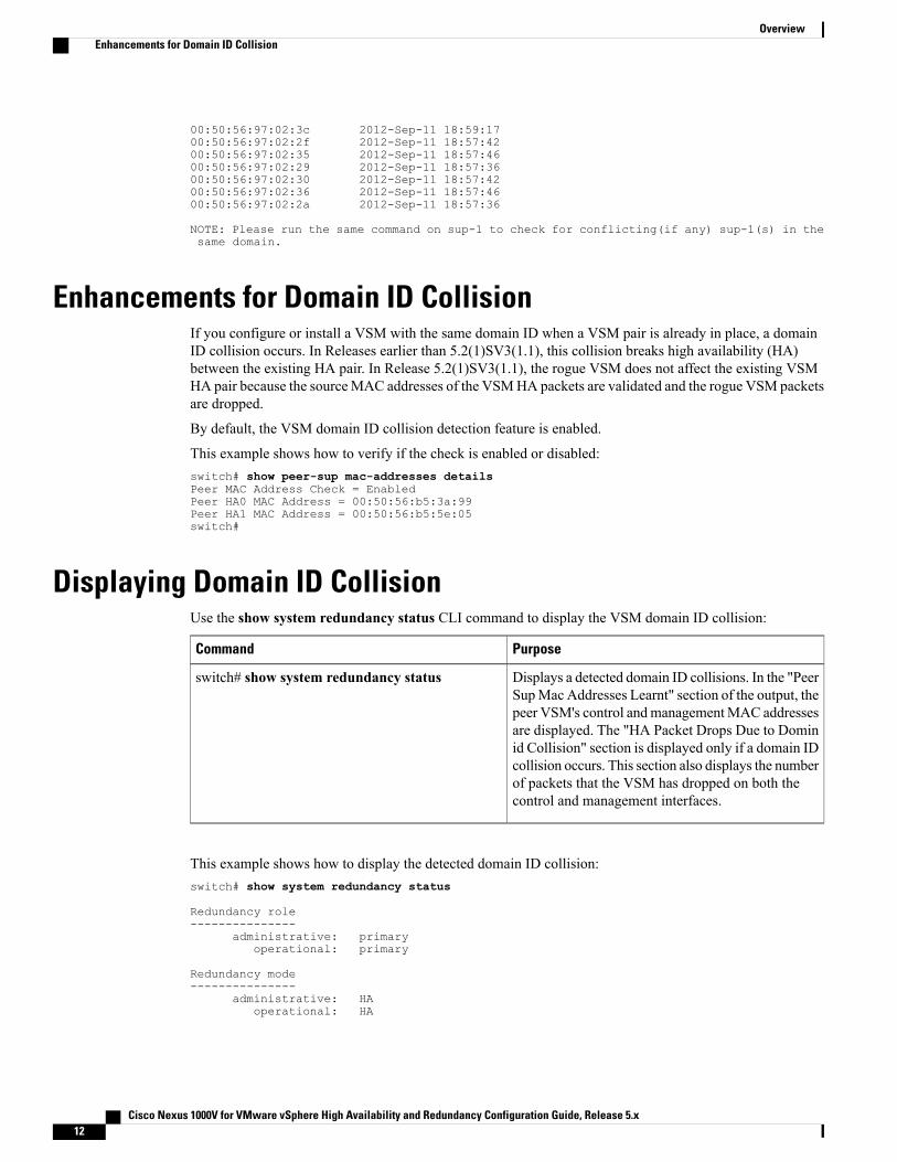
Enhancements for Domain ID CollisionIf you configure or install a VSM with the same domain ID when a VSM pair is already in place, a domainID collision occurs. In Releases earlier than 5.2(1)SV3(1.1), this collision breaks high availability (HA)between the existing HA pair. In Release 5.2(1)SV3(1.1), the rogue VSM does not affect the existing VSMHA pair because the sourceMAC addresses of the VSMHA packets are validated and the rogue VSM packetsare dropped.
By default, the VSM domain ID collision detection feature is enabled.
This example shows how to verify if the check is enabled or disabled:switch# show peer-sup mac-addresses detailsPeer MAC Address Check = EnabledPeer HA0 MAC Address = 00:50:56:b5:3a:99Peer HA1 MAC Address = 00:50:56:b5:5e:05switch#
Displaying Domain ID CollisionUse the show system redundancy status CLI command to display the VSM domain ID collision:
PurposeCommand
Displays a detected domain ID collisions. In the "PeerSupMac Addresses Learnt" section of the output, thepeer VSM's control andmanagementMAC addressesare displayed. The "HA Packet Drops Due to Dominid Collision" section is displayed only if a domain IDcollision occurs. This section also displays the numberof packets that the VSM has dropped on both thecontrol and management interfaces.
switch# show system redundancy status
This example shows how to display the detected domain ID collision:switch# show system redundancy status
Redundancy role---------------
administrative: primaryoperational: primary
Redundancy mode---------------
administrative: HAoperational: HA
Cisco Nexus 1000V for VMware vSphere High Availability and Redundancy Configuration Guide, Release 5.x12
OverviewEnhancements for Domain ID Collision

This supervisor (sup-1)-----------------------
Redundancy state: ActiveSupervisor state: ActiveInternal state: Active with HA standby
Other supervisor (sup-2)------------------------
Redundancy state: StandbySupervisor state: HA standbyInternal state: HA standby
Peer Sup Mac Addresses Learnt--------------------------------------------
Control Interface: 00:50:56:91:44:c8Mgmt Interface: 00:50:56:91:1f:6f
HA Packet Drops Due to Domain id Collision--------------------------------------------
Control Interface: 109Mgmt Interface: 93
Recommended Reading• Cisco Nexus 1000V Installation and Upgrade Guide
• Cisco Nexus 1000V Port Profile Configuration Guide
Cisco Nexus 1000V for VMware vSphere High Availability and Redundancy Configuration Guide, Release 5.x 13
OverviewRecommended Reading

Cisco Nexus 1000V for VMware vSphere High Availability and Redundancy Configuration Guide, Release 5.x14
OverviewRecommended Reading

C H A P T E R 3Understanding Service-Level High Availability
This chapter contains the following sections:
• Information About Cisco NX-OS Service Restarts, page 15
• Restartability Infrastructure, page 15
• Process Restartability, page 17
• Restarts on Standby Supervisor Services , page 19
• Restarts on Switching Module Services, page 19
• Troubleshooting Restarts, page 19
• MIBs, page 19
• RFCs, page 20
• Technical Assistance, page 20
Information About Cisco NX-OS Service RestartsThe Cisco NX-OS service restart feature restarts a faulty service without restarting the supervisor to preventprocess-level failures from causing system-level failures. A service is restarted depending on current errors,failure circumstances, and the high-availability policy for the service. A service can undergo either a statefulor stateless restart. Cisco NX-OS allows services to store run-time state information and messages for a statefulrestart. In a stateful restart, the service can retrieve this stored state information and resume operations fromthe last checkpoint service state. In a stateless restart, the service can initialize and run as if it had just beenstarted with no prior state.
Restartability InfrastructureCisco NX-OS allows stateful restarts of most processes and services. The back-end management andorchestration of processes, services, and applications within a platform are handled by a set of high-levelsystem-control services.
Cisco Nexus 1000V for VMware vSphere High Availability and Redundancy Configuration Guide, Release 5.x 15

System ManagerThe SystemManager directs the overall system function, service management, and system health monitoring,and enforces high-availability policies. The SystemManager is responsible for launching, stopping, monitoring,and restarting services and for initiating and managing the synchronization of service states and supervisorstates for stateful switchovers.
The SystemManager directs the overall system function, service management, and system health monitoring.The System Manager is responsible for launching, stopping, monitoring, and restarting services.
The SystemManager directs the overall system function, service management, and system health monitoring,and enforces high-availability policies. The SystemManager is responsible for launching, stopping, monitoring,and restarting services and for initiating and managing the synchronization of service states and supervisorstates for stateful switchovers.
Persistent Storage ServiceCisco NX-OS services use the persistent storage service (PSS) to store and manage the operational run-timeinformation and configuration of platform services. The PSS component works with system services to recoverstates in the event of a service restart. PSS functions as a database of state and run-time information, whichallows services to make a checkpoint of their state information whenever needed. A restarting service canrecover the last known operating state that preceded a failure, which allows for a stateful restart.
Each service that uses PSS can define its stored information as one of the following:
• Private—It can be read only by that service.
• Shared—The information can be read by other services.
The service can specify that it is one of the following:
• Local—The information can be read only by services on the same supervisor.
• Global—It can be read by services on either supervisor.
Message and Transaction ServiceThemessage and transaction service (MTS) is a high-performance interprocess communications (IPC)messagebroker that specializes in high-availability semantics. MTS handles message routing and queuing betweenservices on and across modules and between supervisors. MTS facilitates the exchange of messages such asevent notification, synchronization, andmessage persistency between system services and system components.MTS can maintain persistent messages and logged messages in queues for access even after a service restart.
High Availability PoliciesCisco NX-OS allows each service to have an associated set of internal HA policies that define how a failedservice will be restarted. Each service can have four defined policies—a primary and secondary policy whentwo supervisors are present, and a primary and secondary policy when only one supervisor is present. If noHA policy is defined for a service, the default HA policy to be performed upon a service failure will be aswitchover if two supervisors are present or a supervisor reset if only one supervisor is present.
Cisco Nexus 1000V for VMware vSphere High Availability and Redundancy Configuration Guide, Release 5.x16
Understanding Service-Level High AvailabilitySystem Manager
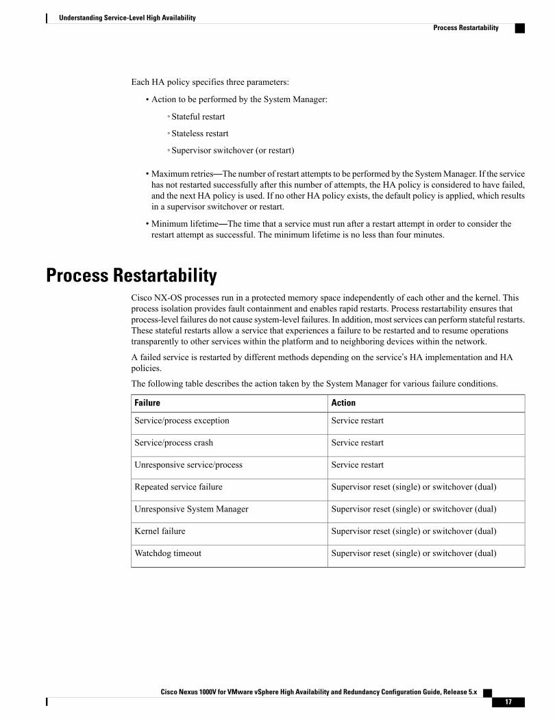
Each HA policy specifies three parameters:
• Action to be performed by the System Manager:
◦Stateful restart
◦Stateless restart
◦Supervisor switchover (or restart)
• Maximum retries—The number of restart attempts to be performed by the SystemManager. If the servicehas not restarted successfully after this number of attempts, the HA policy is considered to have failed,and the next HA policy is used. If no other HA policy exists, the default policy is applied, which resultsin a supervisor switchover or restart.
• Minimum lifetime—The time that a service must run after a restart attempt in order to consider therestart attempt as successful. The minimum lifetime is no less than four minutes.
Process RestartabilityCisco NX-OS processes run in a protected memory space independently of each other and the kernel. Thisprocess isolation provides fault containment and enables rapid restarts. Process restartability ensures thatprocess-level failures do not cause system-level failures. In addition, most services can perform stateful restarts.These stateful restarts allow a service that experiences a failure to be restarted and to resume operationstransparently to other services within the platform and to neighboring devices within the network.
A failed service is restarted by different methods depending on the service’s HA implementation and HApolicies.
The following table describes the action taken by the System Manager for various failure conditions.
ActionFailure
Service restartService/process exception
Service restartService/process crash
Service restartUnresponsive service/process
Supervisor reset (single) or switchover (dual)Repeated service failure
Supervisor reset (single) or switchover (dual)Unresponsive System Manager
Supervisor reset (single) or switchover (dual)Kernel failure
Supervisor reset (single) or switchover (dual)Watchdog timeout
Cisco Nexus 1000V for VMware vSphere High Availability and Redundancy Configuration Guide, Release 5.x 17
Understanding Service-Level High AvailabilityProcess Restartability

Stateful RestartsWhen a restartable service fails, it is restarted on the same supervisor. If the new instance of the servicedetermines that the previous instance was abnormally terminated by the operating system, the service thendetermines whether a persistent context exists. The initialization of the new instance attempts to read thepersistent context to build a run-time context that makes the new instance appear like the previous one. Afterthe initialization is complete, the service resumes the tasks that it was performing when it stopped. Duringthe restart and initialization of the new instance, other services are unaware of the service failure. Anymessagesthat are sent by other services to the failed service are available from the MTS when the service resumes.
Whether or not the new instance survives the stateful initialization depends on the cause of the failure of theprevious instance. If the service is unable to survive a few subsequent restart attempts, the restart is consideredas failed. In this case, the System Manager executes the action specified by the service’s HA policy, forcingeither a stateless restart, no restart, or a supervisor switchover or reset.
During a successful stateful restart, there is no delay while the system reaches a consistent state. Statefulrestarts reduce the system recovery time after a failure.
The events before, during, and after a stateful restart are as follows:
1 The running services make a checkpoint of their run-time state information to the PSS.
2 The System Manager monitors the health of the running services that use heartbeats.
3 The System Manager restarts a service instantly when it crashes or hangs.
4 After restarting, the service recovers its state information from the PSS and resumes all pending transactions.
5 If the service does not resume a stable operation after multiple restarts, the System Manager initiates areset or switchover of the supervisor.
6 Cisco NX-OS will collect the process stack and core for debugging purposes with an option to transfercore files to a remote location.
When a stateful restart occurs, Cisco NX-OS sends a syslog message of level LOG_ERR. If SNMP traps areenabled, the SNMP agent sends a trap.
Stateless RestartsCisco NX-OS infrastructure components manage stateless restarts. During a stateless restart, the SystemManager identifies the failed process and replaces it with a new process. The service that failed does notmaintain its run-time state upon the restart, so the service can either build the run-time state from the runningconfiguration, or if necessary, exchange information with other services to build a run-time state.
When a stateless restart occurs, Cisco NX-OS sends a syslog message of level LOG_ERR. If SNMP traps areenabled, the SNMP agent sends a trap.
SwitchoversIf a standby supervisor is available, Cisco NX-OS performs a supervisor switchover rather than a supervisorrestart whenever multiple failures occur at the same time, because these cases are considered unrecoverableon the same supervisor. For example, if more than one HA application fails, that is considered an unrecoverablefailure.
Cisco Nexus 1000V for VMware vSphere High Availability and Redundancy Configuration Guide, Release 5.x18
Understanding Service-Level High AvailabilityStateful Restarts
In a system with dual VSMs, after a switchover, the active supervisor resets and comes back up as a standbysupervisor.
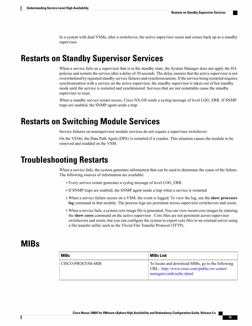
Restarts on Standby Supervisor ServicesWhen a service fails on a supervisor that is in the standby state, the System Manager does not apply the HApolicies and restarts the service after a delay of 30 seconds. The delay ensures that the active supervisor is notoverwhelmed by repeated standby service failures and synchronizations. If the service being restarted requiressynchronization with a service on the active supervisor, the standby supervisor is taken out of hot standbymode until the service is restarted and synchronized. Services that are not restartable cause the standbysupervisor to reset.
When a standby service restart occurs, Cisco NX-OS sends a syslog message of level LOG_ERR. If SNMPtraps are enabled, the SNMP agent sends a trap.
Restarts on Switching Module ServicesService failures on nonsupervisor module services do not require a supervisor switchover.
On the VEMs, the Data Path Agent (DPA) is restarted if it crashes. This situation causes the module to beremoved and readded on the VSM.
Troubleshooting RestartsWhen a service fails, the system generates information that can be used to determine the cause of the failure.The following sources of information are available:
• Every service restart generates a syslog message of level LOG_ERR.
• If SNMP traps are enabled, the SNMP agent sends a trap when a service is restarted
• When a service failure occurs on a VSM, the event is logged. To view the log, use the show processeslog command in that module. The process logs are persistent across supervisor switchovers and resets.
• When a service fails, a system core image file is generated. You can view recent core images by enteringthe show cores command on the active supervisor . Core files are not persistent across supervisorswitchovers and resets, but you can configure the system to export core files to an external server usinga file transfer utility such as the Trivial File Transfer Protocol (TFTP).
MIBsMIBs LinkMIBs
To locate and download MIBs, go to the followingURL: http://www.cisco.com/public/sw-center/netmgmt/cmtk/mibs.shtml
CISCO-PROCESS-MIB
Cisco Nexus 1000V for VMware vSphere High Availability and Redundancy Configuration Guide, Release 5.x 19
Understanding Service-Level High AvailabilityRestarts on Standby Supervisor Services

RFCsNo RFCs are supported by this feature.
Technical AssistanceTechnical Assistance Center (TAC) home page, containing 30,000 pages of searchable technical content,including links to products, technologies, solutions, technical tips, and tools. Registered Cisco.com users canlog in from this page to access even more content.
Go to the following URL: http://www.cisco.com/cisco/web/support/index.html
Cisco Nexus 1000V for VMware vSphere High Availability and Redundancy Configuration Guide, Release 5.x20
Understanding Service-Level High AvailabilityRFCs

C H A P T E R 4Configuring System-Level High Availability
This chapter contains the following sections:
• Information About System-Level High Availability, page 22
• Information About VSM Restarts and Switchovers, page 24
• Guidelines and Limitations, page 25
• Configuring System-Level High Availability, page 25
• Adding a Second VSM to a Standalone System, page 30
• Replacing the Secondary VSM in a Dual VSM System, page 32
• Replacing the Primary VSM in a Dual VSM System, page 32
• Changing the Domain ID in a Dual VSM System, page 33
• Changing the Domain ID in a Dual VSM System for VSMs Hosted on Cisco Nexus 1010, page 35
• Disabling Domain ID Collision , page 37
• Verifying the HA Status, page 38
• Related Documents, page 39
• Standards, page 39
• MIBs, page 39
• RFCs, page 40
• Technical Assistance, page 40
• Feature History for System-Level High Availability, page 40
Cisco Nexus 1000V for VMware vSphere High Availability and Redundancy Configuration Guide, Release 5.x 21

Information About System-Level High Availability
Information About Single and Dual Supervisor RolesThe Cisco Nexus 1000V can be configured with a single Virtual Supervisor Module (VSM) or dual VSMs.The following table describes the HA supervisor roles for single and dual VSM operation.
Dual VSM OperationSingle VSM Operation
• Redundancy is provided by one active VSM and onestandby VSM.
• The active VSM runs all the system applications andcontrols the system.
• On the standby VSM, the applications are started andinitialized in standby mode. The applications aresynchronized and kept up to date with the active VSM inorder to be ready to run.
• On a switchover, the standby VSM takes over for theactive VSM.
• The control interface of the VSMs are used to passheartbeats between the two VSMs.
• The management interface is used to prevent split-brainscenarios.
• Stateless—In case of failure, servicerestarts from the startupconfiguration.
• Stateful—In case of failure, serviceresumes from previous state.
HA Supervisor RolesThe redundancy role indicates not only whether the VSM interacts with other VSMs, but also the modulenumber it occupies. The following table shows the available HA roles for VSMs.
DescriptionModuleNumber
role
• This role does not interact with other VSMs.
• You assign this role when there is only one VSM in thesystem.
• This role is the default.
1Standalone
Cisco Nexus 1000V for VMware vSphere High Availability and Redundancy Configuration Guide, Release 5.x22
Configuring System-Level High AvailabilityInformation About System-Level High Availability
DescriptionModuleNumber
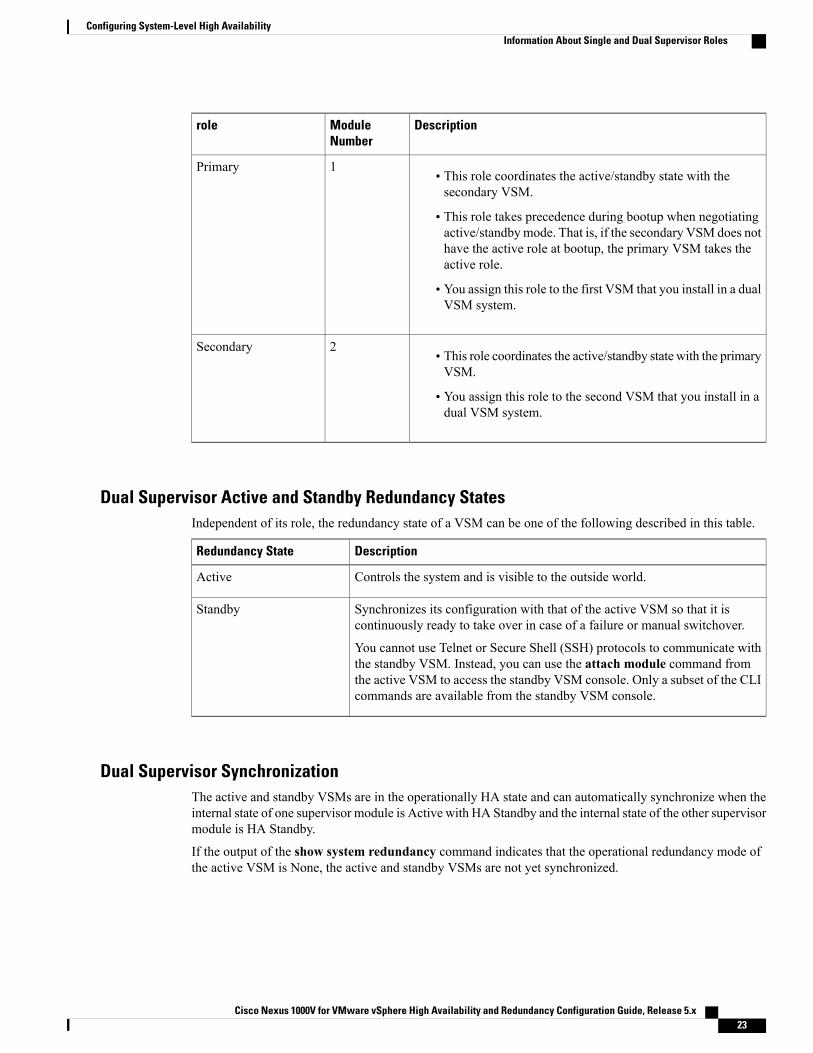
role
• This role coordinates the active/standby state with thesecondary VSM.
• This role takes precedence during bootup when negotiatingactive/standbymode. That is, if the secondary VSM does nothave the active role at bootup, the primary VSM takes theactive role.
• You assign this role to the first VSM that you install in a dualVSM system.
1Primary
• This role coordinates the active/standby state with the primaryVSM.
• You assign this role to the second VSM that you install in adual VSM system.
2Secondary
Dual Supervisor Active and Standby Redundancy StatesIndependent of its role, the redundancy state of a VSM can be one of the following described in this table.
DescriptionRedundancy State
Controls the system and is visible to the outside world.Active
Synchronizes its configuration with that of the active VSM so that it iscontinuously ready to take over in case of a failure or manual switchover.
You cannot use Telnet or Secure Shell (SSH) protocols to communicate withthe standby VSM. Instead, you can use the attach module command fromthe active VSM to access the standby VSM console. Only a subset of the CLIcommands are available from the standby VSM console.
Standby
Dual Supervisor SynchronizationThe active and standby VSMs are in the operationally HA state and can automatically synchronize when theinternal state of one supervisor module is Active with HA Standby and the internal state of the other supervisormodule is HA Standby.
If the output of the show system redundancy command indicates that the operational redundancy mode ofthe active VSM is None, the active and standby VSMs are not yet synchronized.
Cisco Nexus 1000V for VMware vSphere High Availability and Redundancy Configuration Guide, Release 5.x 23
Configuring System-Level High AvailabilityInformation About Single and Dual Supervisor Roles

This example shows the VSM internal state of dual supervisors as observed in the output of the show systemredundancy status command:switch# show system redundancy statusRedundancy role---------------
administrative: standaloneoperational: standalone
Redundancy mode---------------
administrative: HAoperational: None
This supervisor (sup-1)-----------------------
Redundancy state: ActiveSupervisor state: ActiveInternal state: Active with no standby
Other supervisor (sup-2)------------------------
Redundancy state: Not presentswitch#
Information About VSM Restarts and Switchovers
Restarts on Standalone VSMsIn a system with only one supervisor, when all HA policies have been unsuccessful in restarting a service,the supervisor restarts. The supervisor and all services restart with no prior state information.
Restarts on Dual VSMsWhen a VSM fails in a system with dual supervisors, the system performs a switchover rather than a systemrestart in order to maintain a stateful operation. In some cases, a switchover might not be possible at the timeof the failure. For example, if the standby VSM is not in a stable standby state, a restart rather than a switchoveris performed.
Switchovers on Dual VSMsA dual VSM configuration allows uninterrupted traffic forwarding with a stateful switchover (SSO) when afailure occurs in the VSM. The two VSMs operate in an active/standby capacity in which only one is activeat any given time, while the other acts as a standby backup. The two VSMs constantly synchronize the stateand configuration to provide a seamless and stateful switchover of most services if the active VSM fails.
Switchover CharacteristicsA switchover occurs when the active supervisor fails (for example, if repeated failures occur in an essentialservice or if the system that is hosting the VSM fails).
A user-triggered switchover could occur (for example, if you need to performmaintenance tasks on the systemhosting the active VSM).
Cisco Nexus 1000V for VMware vSphere High Availability and Redundancy Configuration Guide, Release 5.x24
Configuring System-Level High AvailabilityInformation About VSM Restarts and Switchovers

An HA switchover has the following characteristics:
• It is stateful (nondisruptive) because the control traffic is not affected.
• It does not disrupt data traffic because the VEMs are not affected.
Automatic SwitchoversWhen a stable standby VSM detects that the active VSM has failed, it initiates a switchover and transitionsto active. When a switchover begins, another switchover cannot be started until a stable standby VSM isavailable.
If a standby VSM that is not stable detects that the active VSM has failed, then, instead of initiating aswitchover, it tries to restart the system.
Manual SwitchoversBefore you can initiate a manual switchover from the active to the standby VSM, the standby VSM must bestable.
Once you have verified that the standby VSM is stable, you can manually initiate a switchover.
Once a switchover process begins, another switchover process cannot be started until a stable standby VSMis available.
Guidelines and Limitations• Although primary and secondary VSMs can reside in the same host, to improve redundancy, install themin separate hosts and, if possible, connect the VSMs to different upstream switches.
• The console for the standby VSM is available through the vSphere client or by entering themoduleattach x command, but configuration is not allowed and many commands are restricted. Enter thiscommand at the console of the active VSM.
• You cannot use Telnet or Secure Shell (SSH) protocols to communicate with the standby VSM becausethe management interface IP is unconfigured until the VSM becomes active.
• The active and standby VSMs must be on the same management subnet.
Configuring System-Level High Availability
Changing the VSM RoleThe Cisco Nexus 1000V VSM software installation provides an opportunity for you to designate the role foreach VSM. You can use this procedure to change that initial configuration.
Cisco Nexus 1000V for VMware vSphere High Availability and Redundancy Configuration Guide, Release 5.x 25
Configuring System-Level High AvailabilityGuidelines and Limitations

Changing the role of a VSM can result in a conflict between the VSM pair. If a primary and secondaryVSM see each other as active at the same time, the system resolves this problem by resetting the primaryVSM.
Caution
Use this procedure to change the role of a VSM to one of the following after it is already in service:
• Standalone
• Primary
• Secondary
Before You Begin
• Log in to the CLI in EXEC mode.
• If you are changing a standalone VSM to a secondary VSM, be sure to first isolate it from the otherVSM in the pair to prevent any interaction with the primary VSM during the change. Power the VM offfrom the vSphere Client before reconnecting it as standby.
For an example on how to change the port groups and port profiles assigned to the VSM interfaces in thevSphere Client, see theCisco Nexus 1000V Installation and Upgrade Guide.
You must understand the following information:
• The possible HA roles are standalone, primary, and secondary.
• The possible HA redundancy states are active and standby.
• To activate a change from primary to secondary VSM, you must reload the VSM by doing one of thefollowing:
◦Enter the reload command.
◦Power the VM off and then on from the vSphere Client.
• A change from a standalone to a primary VSM takes effect immediately.
Procedure
PurposeCommand or Action
Designates the HA role of the VSM.switch# system redundancy role{standalone|primary|secondary}
Step 1
(Optional)Displays the current redundancy status for theVSMs.
switch# show system redundancy statusStep 2
(Optional)Saves the change persistently through reboots andrestarts by copying the running configuration to thestartup configuration.
switch# copy running-configstartup-config
Step 3
Cisco Nexus 1000V for VMware vSphere High Availability and Redundancy Configuration Guide, Release 5.x26
Configuring System-Level High AvailabilityChanging the VSM Role

This example shows how to change the VSM role:switch# system redundancy role standaloneswitch# show system redundancy statusRedundancy role---------------
administrative: standaloneoperational: standalone
Redundancy mode---------------
administrative: HAoperational: None
This supervisor (sup-1)-----------------------
Redundancy state: ActiveSupervisor state: ActiveInternal state:Active with no standby
Other supervisor (sup-2)------------------------
Redundancy state: Not presentswitch#
Configuring a Switchover
Guidelines and Limitations for Configuring a Switchover• When you manually initiate a switchover, system messages are generated that indicate the presence oftwo VSMs and identify which one is becoming active.
• A switchover can only be performed when both VSMs are functioning.
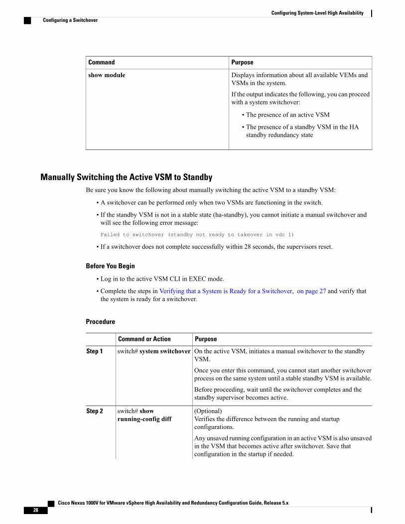
Verifying that a System is Ready for a SwitchoverUse one of the following commands to verify the configuration:
PurposeCommand
Displays the current redundancy status for theVSM(s).
If the output indicates the following, you can proceedwith a system switchover:
• The presence of an active VSM
• The presence of a standby VSM in the HAstandby redundancy state
show system redundancy status
Cisco Nexus 1000V for VMware vSphere High Availability and Redundancy Configuration Guide, Release 5.x 27
Configuring System-Level High AvailabilityConfiguring a Switchover
PurposeCommand
Displays information about all available VEMs andVSMs in the system.
If the output indicates the following, you can proceedwith a system switchover:
• The presence of an active VSM
• The presence of a standby VSM in the HAstandby redundancy state
show module
Manually Switching the Active VSM to StandbyBe sure you know the following about manually switching the active VSM to a standby VSM:
• A switchover can be performed only when two VSMs are functioning in the switch.
• If the standby VSM is not in a stable state (ha-standby), you cannot initiate a manual switchover andwill see the following error message:
Failed to switchover (standby not ready to takeover in vdc 1)
• If a switchover does not complete successfully within 28 seconds, the supervisors reset.
Before You Begin
• Log in to the active VSM CLI in EXEC mode.
• Complete the steps in Verifying that a System is Ready for a Switchover, on page 27 and verify thatthe system is ready for a switchover.
Procedure
PurposeCommand or Action
On the active VSM, initiates a manual switchover to the standbyVSM.
switch# system switchoverStep 1
Once you enter this command, you cannot start another switchoverprocess on the same system until a stable standby VSM is available.
Before proceeding, wait until the switchover completes and thestandby supervisor becomes active.
(Optional)Verifies the difference between the running and startupconfigurations.
switch# showrunning-config diff
Step 2
Any unsaved running configuration in an active VSM is also unsavedin the VSM that becomes active after switchover. Save thatconfiguration in the startup if needed.
Cisco Nexus 1000V for VMware vSphere High Availability and Redundancy Configuration Guide, Release 5.x28
Configuring System-Level High AvailabilityConfiguring a Switchover

PurposeCommand or Action
(Optional)Saves the change persistently through reboots and restarts by copyingthe running configuration to the startup configuration.
switch# copyrunning-configstartup-config
Step 3
This example shows how to switch an active VSM to the standby VSM and displays the output that appearson the standby VSM as it becomes the active VSM:switch# system switchover----------------------------2009 Mar 31 04:21:56 n1000v %$ VDC-1 %$ %SYSMGR-2-HASWITCHOVER_PRE_START:This supervisor is becoming active (pre-start phase).2009 Mar 31 04:21:56 n1000v %$ VDC-1 %$ %SYSMGR-2-HASWITCHOVER_START:This supervisor is becoming active.2009 Mar 31 04:21:57 n1000v %$ VDC-1 %$ %SYSMGR-2-SWITCHOVER_OVER: Switchover completed.2009 Mar 31 04:22:03 n1000v %$ VDC-1 %$ %PLATFORM-2-MOD_REMOVE: Module 1 removed (Serialnumber )
This example shows how to display the difference between the running and startup configurations:switch# show running-config diff*** Startup-config--- Running-config****************** 1,38 ****version 4.0(4)SV1(1)role feature-group name newrole name testroleusername admin password 5 $1$S7HvKc5G$aguYqHl0dPttBJAhEPwsy1 role network-admintelnet server enableip domain-lookup
Configuring the VSM-to-VSM Heartbeat IntervalIf the communication network between two VSMs in an HA pair experiences interruptions longer than the15-second default, you can change the VSM-to-VSM heartbeat interval so that it is less sensitive to falselydetecting active VSM failures.
Procedure
PurposeCommand or Action
Enters global configuration mode.switch# configure terminalStep 1
Configures the VSM-to-VSM heartbeat with a timeinterval from 6 to 30 seconds. The default is 15seconds.
switch(config)# systeminter-sup-heartbeat time time-interval
Step 2
Displays the heartbeat interval setting in the runningconfiguration.
switch(config)# show running-config |grep heartbeat
Step 3
(Optional)Saves the change persistently through reboots andrestarts by copying the running configuration to thestartup configuration.
switch(config)# copy running-configstartup-config
Step 4
Cisco Nexus 1000V for VMware vSphere High Availability and Redundancy Configuration Guide, Release 5.x 29
Configuring System-Level High AvailabilityConfiguring a Switchover
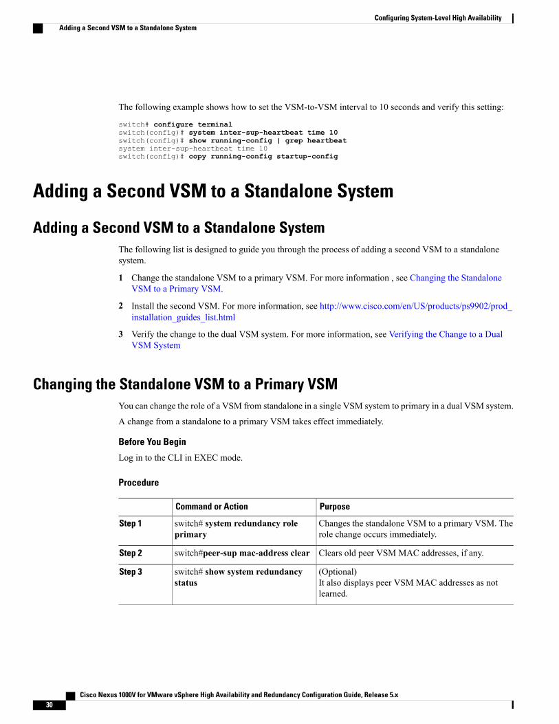
The following example shows how to set the VSM-to-VSM interval to 10 seconds and verify this setting:
switch# configure terminalswitch(config)# system inter-sup-heartbeat time 10switch(config)# show running-config | grep heartbeatsystem inter-sup-heartbeat time 10switch(config)# copy running-config startup-config
Adding a Second VSM to a Standalone System
Adding a Second VSM to a Standalone SystemThe following list is designed to guide you through the process of adding a second VSM to a standalonesystem.
1 Change the standalone VSM to a primary VSM. For more information , see Changing the StandaloneVSM to a Primary VSM.
2 Install the second VSM. For more information, see http://www.cisco.com/en/US/products/ps9902/prod_installation_guides_list.html
3 Verify the change to the dual VSM system. For more information, see Verifying the Change to a DualVSM System
Changing the Standalone VSM to a Primary VSMYou can change the role of a VSM from standalone in a single VSM system to primary in a dual VSM system.
A change from a standalone to a primary VSM takes effect immediately.
Before You Begin
Log in to the CLI in EXEC mode.
Procedure
PurposeCommand or Action
Changes the standalone VSM to a primary VSM. Therole change occurs immediately.
switch# system redundancy roleprimary
Step 1
Clears old peer VSM MAC addresses, if any.switch#peer-sup mac-address clearStep 2
(Optional)It also displays peer VSM MAC addresses as notlearned.
switch# show system redundancystatus
Step 3
Cisco Nexus 1000V for VMware vSphere High Availability and Redundancy Configuration Guide, Release 5.x30
Configuring System-Level High AvailabilityAdding a Second VSM to a Standalone System

PurposeCommand or Action
(Optional)Saves the change persistently through reboots andrestarts by copying the running configuration to thestartup configuration.
switch# copy running-configstartup-config
Step 4
This example shows how to display the current system redundancy status for the VSM:switch# system redundancy role primaryswitch# peer-sup mac-address clearswitch# show system redundancy statusRedundancy role---------------
administrative: primaryoperational: primary
Redundancy mode---------------
administrative: HAoperational: None
This supervisor (sup-1)-----------------------
Redundancy state: ActiveSupervisor state: ActiveInternal state: Active with no standby
Other supervisor (sup-2)------------------------
Redundancy state: Not present
Peer Sup Mac Addresses Learnt--------------------------------------------
Control Interface: Not LearntMgmt Interface: Not Learn
switch# copy running-config startup-config
Verifying the Change to a Dual VSM SystemUse one of the following commands to verify the configuration:
PurposeCommand
Displays the current redundancy status for VSMs inthe system.
show system redundancy status
Displays information about all available VSMs andVEMs in the system.
show module
Cisco Nexus 1000V for VMware vSphere High Availability and Redundancy Configuration Guide, Release 5.x 31
Configuring System-Level High AvailabilityVerifying the Change to a Dual VSM System

Replacing the Secondary VSM in a Dual VSM System
Equipment Outage—This procedure requires that you power down and reinstall a VSM. During this time,your system will operate with a single VSM.
If have your VSM HA Pair in 5.2(1)SV3(1.1) with Domain Id > 1023 [ Setup created Via upgrade] , thenkindly change your domain ID to less than 1024 before replacing Primary or Secondary VSM in an DualVSM system.
Note
Procedure
Step 1 Ensure that the primary VSM is active (see the output of the show system redundancy statuscommand).Do a system switchover ifnecessary.
Note
Step 2 Power off the secondary VSM.Step 3 Log into the CLI in EXECmode on the active primary VSM. Enter peer-supmac-addresses-clearcommand.Step 4 Verify that the "Peer Sup Mac Addresses Learnt" section in the show system redundancy status command
displays "Not Learnt."Step 5 Install the new VSM as a secondary, with the same domain ID as the existing VSM, using the procedure in
the “Installing and Configuring the VSM VM” section in the Cisco Nexus 1000V Installation and UpgradeGuide.After the newVSM is added to the system, both VSMs learn the peer VSMMAC addresses and the newVSMsynchronizes with the existing VSM.
Replacing the Primary VSM in a Dual VSM SystemYou can replace an active/primary VSM in a dual VSM system.
Equipment Outage—This procedure requires that you power down and reinstall a VSM. During this time,your system will operate with a single VSM.
If have your VSM HA Pair in 5.2(1)SV3(1.1) with Domain Id > 1023 [ Setup created Via upgrade] , thenkindly change your domain ID to less than 1024 before replacing Primary or Secondary VSM in an DualVSM system.
Note
Before You Begin
• Log in to the CLI in EXEC mode.
• Power off the primary VSM.
Cisco Nexus 1000V for VMware vSphere High Availability and Redundancy Configuration Guide, Release 5.x32
Configuring System-Level High AvailabilityReplacing the Secondary VSM in a Dual VSM System

• Configure the port groups so that the new primary VSM cannot communicate with the secondary VSMor any of the VEMs during the setup. VSMs with a primary or secondary redundancy role have built-inmechanisms for detecting and resolving the conflict between two VSMs in the active state. To avoidthese mechanisms during the configuration of the new primary VSM, you must isolate the new primaryVSM from the secondary VSM.
Procedure
Step 1 Ensure that the secondary VSM is active.Do a system switchover ifnecessary.
Note
Step 2 Log into CLI in EXEC mode on the active secondary VSM. Enter peer-sup mac-addresses-clear command.Step 3 Verify that the "Peer Sup Mac Addreses Learnt" section in the show system redundancy status command
displays "Not Learnt."Step 4 On the vSphere Client, change the port group configuration for the new primary VSM VM to prevent
communication with the secondary VSM and the VEMs during the setup.For an example on how to change the port groups and port profiles assigned to the VSM interfaces in thevSphere Client, see the Cisco Nexus 1000V Installation and Upgrade Guide.
Step 5 Install the new VSM as a primary, with the same domain ID as the existing VSM, using the “Installing andConfiguring the VSM VM” section in the Cisco Nexus 1000V Installation and Upgrade Guide.
Step 6 Save the configuration.Step 7 Power off the VM.Step 8 On the vSphere Client, change the port group configuration for the new primary VSM to permit communication
with the secondary VSM and the VEMs.Step 9 Power up the new primary VSM. Both VSMs will learn the peer VSM's MAC addresses.
The new primary VSM starts and automatically synchronizes all configuration data with the secondary VSM,which is currently the active VSM. Because the existing VSM is active, the new primary VSM becomes thestandby VSM and receives all configuration data from the existing active VSM.
Changing the Domain ID in a Dual VSM SystemBefore You Begin
• Have access to the console of both the active and standby VSM.
• Isolate the standby VSM from the active VSM to avoid the built-in mechanisms that detect and resolveconflict between two VSMs with a primary or secondary redundancy role. This procedure has a step forisolating the VSMs.
Equipment Outage—This procedure requires that you power down a VSM. During this time, your systemwill operate with a single VSM.
Note
Cisco Nexus 1000V for VMware vSphere High Availability and Redundancy Configuration Guide, Release 5.x 33
Configuring System-Level High AvailabilityChanging the Domain ID in a Dual VSM System

Procedure
Step 1 On the vSphere Client for the standby VSM, do one of the following to isolate the VSMs and prevent theircommunication while completing this procedure:
• Change the port group configuration for the interfaces using port groups that prevent the VSMs fromcommunicating with each other.
• Unmark the “Connected” option for the interfaces.
The standby VSM becomes active but cannot communicate with the other active VSM or the VEM
Step 2 At the console of the standby VSM, change the domain ID and save the configuration.
Example:This example shows how to change the domain ID and save the configuration:switch# configure terminalswitch(config)# svs-domainswitch(config-svs-domain)# domain id 100Successfully cleared old Peer VSM's MAC Addresses======================================================================IMPORTANT NOTE: If this VSM is replacing a Standby VSM which was in HApair then, please execute "peer mac-addresses clear" CLI on Active VSMto clear old Peer VSM's MAC Addresses on Active VSM as well.======================================================================switch(config-svs-domain)# copy running-config startup-configThe domain ID is changed on the standby VSM and the VEM connected to it
Step 3 Power down the standby VSM.Step 4 At the console of the active VSM, change the domain ID and save the configuration.
Example:switch# configure terminalswitch(config)# svs-domainswitch(config-svs-domain)# domain id 100Successfully cleared old Peer VSM's MAC Addresses======================================================================IMPORTANT NOTE: If this VSM is replacing a Standby VSM which was in HApair then, please execute "peer mac-addresses clear" CLI on Active VSMto clear old Peer VSM's MAC Addresses on Active VSM as well.======================================================================
switch(config-svs-domain)# copy running-config startup-configThe domain ID is changed on the active VSM and the VEM that is connected to it.
Step 5 On the vSphere Client for the standby VSM, do one of the following to permit communication with the activeVSM:
• Change the port group configuration for the interfaces.
• Make sure that the "Connect at power on" option is marked for the interfaces.
When the standby VSM is powered up, it will be able to communicate with the active VSM.
Step 6 Power up the standby VSM.Both VSMs are now using the new domain ID and will synchronize.
Cisco Nexus 1000V for VMware vSphere High Availability and Redundancy Configuration Guide, Release 5.x34
Configuring System-Level High AvailabilityChanging the Domain ID in a Dual VSM System
Changing the Domain ID in a Dual VSM System for VSMs Hostedon Cisco Nexus 1010
Before You Begin
• Have access to the CLI of the active VSM (primary VSB) and standby VSM (secondary VSB).
• Have access to the Cisco Nexus 1010 CLI.
Procedure
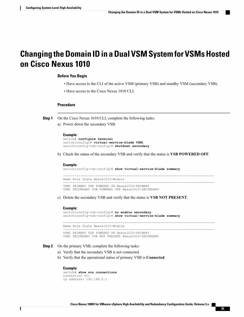
Step 1 On the Cisco Nexus 1010 CLI, complete the following tasks:a) Power down the secondary VSB.
Example:switch# configure terminalswitch(config)# virtual-service-blade VSM1switch(config-vsb-config)# shutdown secondary
b) Check the status of the secondary VSB and verify that the status is VSB POWERED OFF.
Example:switch(config-vsb-config)# show virtual-service-blade summary
-------------------------------------------------------------------------------Name Role State Nexus1010-Module-------------------------------------------------------------------------------VSM1 PRIMARY VSB POWERED ON Nexus1010-PRIMARYVSM1 SECONDARY VSB POWERED OFF Nexus1010-SECONDARY
c) Delete the secondary VSB and verify that the status is VSB NOT PRESENT.
Example:switch(config-vsb-config)# no enable secondaryswitch(config-vsb-config)# show virtual-service-blade summary
-------------------------------------------------------------------------------Name Role State Nexus1010-Module-------------------------------------------------------------------------------VSM1 PRIMARY VSB POWERED ON Nexus1010-PRIMARYVSM1 SECONDARY VSB NOT PRESENT Nexus1010-SECONDARY
Step 2 On the primary VSB, complete the following tasks:a) Verify that the secondary VSB is not connected.b) Verify that the operational status of primary VSB is Connected.
Example:switch# show svs connectionsconnection VC:ip address: 192.168.0.1
Cisco Nexus 1000V for VMware vSphere High Availability and Redundancy Configuration Guide, Release 5.x 35
Configuring System-Level High AvailabilityChanging the Domain ID in a Dual VSM System for VSMs Hosted on Cisco Nexus 1010

protocol: vmware-vim httpscertificate: defaultdatacenter name: Hamilton-DCDVS uuid: ac 36 07 50 42 88 e9 ab-03 fe 4f dd d1 30 cc 5cconfig status: Enabledoperational status: Connected
c) Change the domain ID and save the configuration.
Example:switch# configure terminalswitch(config)# svs-domainswitch(config-svs-domain)# domain id 100Successfully cleared old Peer VSM's MAC Addresses======================================================================IMPORTANT NOTE: If this VSM is replacing a Standby VSM which was in HApair then, please execute "peer mac-addresses clear" CLI on Active VSMto clear old Peer VSM's MAC Addresses on Active VSM as well.======================================================================switch(config-svs-domain)# copy running-config startup-config
d) Verify the new domain ID.
Example:switch(config)# show svs domainSVS domain config:Domain id: 100L2/L3 Control mode: L2L3 control interface: NAStatus: Config push to VC successful.
e) Verify that the domain ID is updated on VEMs by running the following command on the VEMmodules:
Example:switch# vemcmd show cardard UUID type 2: 58f8afd7-e1e3-3c51-85e2-6e6f2819a7b8Card name: sfish-srvr-1Switch name: n1000vSwitch alias: DvsPortset-0Switch uuid: 56 e0 36 50 91 1c 32 7a-e9 9f 31 59 88 0c 7f 76Card domain: 100Card slot: 4VEM Control (Control VLAN) MAC: 00:02:3d:14:00:03VEM Packet (Inband) MAC: 00:02:3d:24:00:03VEM Control Agent (DPA) MAC: 00:02:3d:44:00:03VEM SPAN MAC: 00:02:3d:34:00:03Management IP address: 172.23.232.102Max physical ports: 32Max virtual ports: 216Card control VLAN: 3002Card packet VLAN: 3003
Processors: 4Processor Cores: 4
Processor Sockets: 2Physical Memory: 4290351104
Step 3 On the Cisco Nexus 1010 CLI, complete the following tasks:a) Deploy a secondary VSB.
Example:switch# configure terminalswitch(config)# virtual-service-blade VSM1switch(config-vsb-config)# enable secondaryEnter vsb image: [dcos_vsm.iso]Enter domain id[1-4095]: 100
Cisco Nexus 1000V for VMware vSphere High Availability and Redundancy Configuration Guide, Release 5.x36
Configuring System-Level High AvailabilityChanging the Domain ID in a Dual VSM System for VSMs Hosted on Cisco Nexus 1010

Management IP version [V4/V6]: [V4]Enter Management IP address: 10.78.109.67Enter Management subnet mask length: 27IPv4 address of the default gateway: 10.78.109.65Enter HostName: switchEnter the password for 'admin': xz35vb1zx
b) Check the status of the secondary VSB and verify that the status is VSB POWERED ON.
Example:switch(config-vsb-config)# show virtual-service-blade summary
-------------------------------------------------------------------------------Name Role State Nexus1010-Module-------------------------------------------------------------------------------VSM1 PRIMARY VSB POWERED ON Nexus1010-PRIMARYVSM1 SECONDARY VSB POWERED ON Nexus1010-SECONDARY
Step 4 On the primary VSB, verify that the HA pair is formed.
Example:switch# show system redundancy statusRedundancy role---------------administrative: primaryoperational: primaryRedundancy mode---------------administrative: HAoperational: HAThis supervisor (sup-1)-----------------------Redundancy state: ActiveSupervisor state: ActiveInternal state: Active with HA standbyOther supervisor (sup-2)------------------------Redundancy state: StandbySupervisor state: HA standbyInternal state: HA standby
Disabling Domain ID CollisionProcedure
Step 1 Log in to the primary VSM console in EXEC mode.Step 2 Disable the domain ID collision detection.
Example:switch# peer-sup mac-addresses check disable
Step 3 Verify that the check is disabled.
Example:switch# show peer-sup mac-addresses detailsPeer MAC Address Check = Disabled
Cisco Nexus 1000V for VMware vSphere High Availability and Redundancy Configuration Guide, Release 5.x 37
Configuring System-Level High AvailabilityDisabling Domain ID Collision

Peer HA0 MAC Address = 00:50:56:b5:3a:99Peer HA1 MAC Address = 00:50:56:b5:5e:05
Step 4 Log in to the secondary VSM console in EXEC modeStep 5 Disable the domain id collision detection.
Example:switch# peer-sup mac-addresses check disable
Step 6 Verify that the check is disabled.
Example:switch# show peer-sup mac-addresses detailsPeer MAC Address Check = DisabledPeer HA0 MAC Address = 00:50:56:b5:3a:99Peer HA1 MAC Address = 00:50:56:b5:5e:05
Verifying the HA StatusUse one of the following commands to verify the configuration:
PurposeCommand
Displays the HA status of the system.show system redundancy status
Displays information about all available VSMs andVEMs in the system.
show module
Displays the state of all processes and the start countof the process.
The states and types are described as follows:
• State: R (runnable), S (sleeping), Z (defunct)
• Type: U (unknown), O (non sysmgr), VL(vdc-local), VG (vdc-global), VU(vdc-unaware), NR (not running), ER(terminated)
show processes
Starting with Release 5.2(1)SV3(1.1), the VSM drops the HA packets when the source MAC address is notknown.If the peer VSM's MAC addresses are not learned correctly (such as when a standby VSM is replacedwithout following a correct procedure), the VSM is not formed.
The show system redundancy status command displays a note in this case output. After clearing the oldMAC addresses, HA should be formed if the problem was due to incorrect MAC addresses.switch# show system redundancy status
Redundancy role---------------
administrative: primary
Cisco Nexus 1000V for VMware vSphere High Availability and Redundancy Configuration Guide, Release 5.x38
Configuring System-Level High AvailabilityVerifying the HA Status
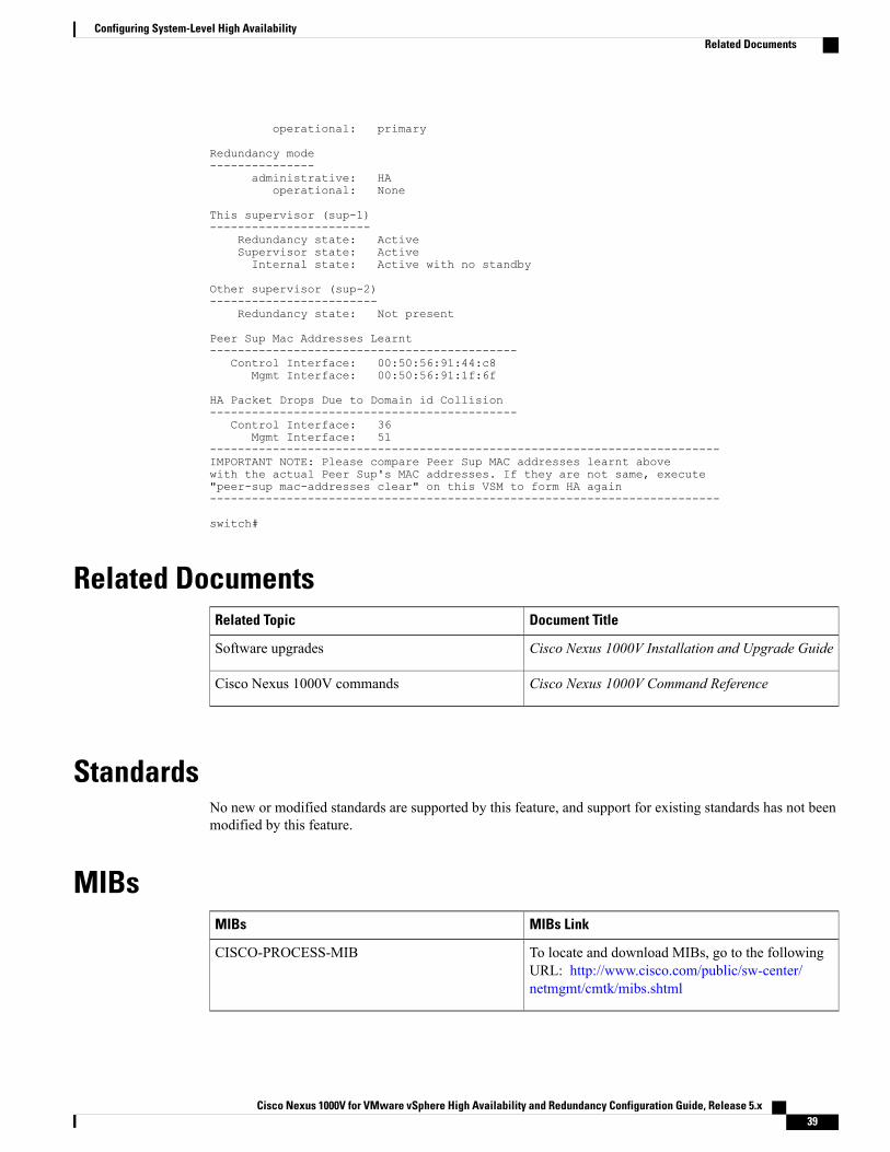
operational: primary
Redundancy mode---------------
administrative: HAoperational: None
This supervisor (sup-1)-----------------------
Redundancy state: ActiveSupervisor state: ActiveInternal state: Active with no standby
Other supervisor (sup-2)------------------------
Redundancy state: Not present
Peer Sup Mac Addresses Learnt--------------------------------------------
Control Interface: 00:50:56:91:44:c8Mgmt Interface: 00:50:56:91:1f:6f
HA Packet Drops Due to Domain id Collision--------------------------------------------
Control Interface: 36Mgmt Interface: 51
-------------------------------------------------------------------------IMPORTANT NOTE: Please compare Peer Sup MAC addresses learnt abovewith the actual Peer Sup's MAC addresses. If they are not same, execute"peer-sup mac-addresses clear" on this VSM to form HA again-------------------------------------------------------------------------
switch#
Related DocumentsDocument TitleRelated Topic
Cisco Nexus 1000V Installation and Upgrade GuideSoftware upgrades
Cisco Nexus 1000V Command ReferenceCisco Nexus 1000V commands
StandardsNo new or modified standards are supported by this feature, and support for existing standards has not beenmodified by this feature.
MIBsMIBs LinkMIBs
To locate and download MIBs, go to the followingURL: http://www.cisco.com/public/sw-center/netmgmt/cmtk/mibs.shtml
CISCO-PROCESS-MIB
Cisco Nexus 1000V for VMware vSphere High Availability and Redundancy Configuration Guide, Release 5.x 39
Configuring System-Level High AvailabilityRelated Documents
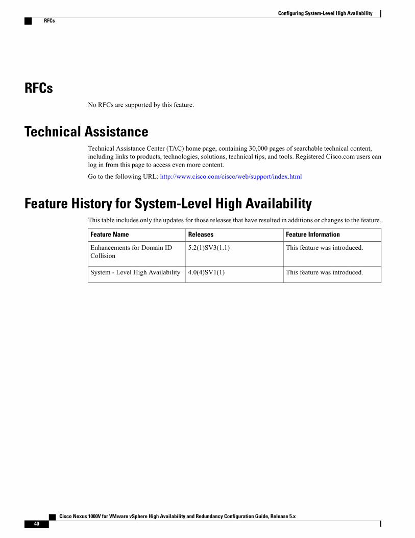
RFCsNo RFCs are supported by this feature.
Technical AssistanceTechnical Assistance Center (TAC) home page, containing 30,000 pages of searchable technical content,including links to products, technologies, solutions, technical tips, and tools. Registered Cisco.com users canlog in from this page to access even more content.
Go to the following URL: http://www.cisco.com/cisco/web/support/index.html
Feature History for System-Level High AvailabilityThis table includes only the updates for those releases that have resulted in additions or changes to the feature.
Feature InformationReleasesFeature Name
This feature was introduced.5.2(1)SV3(1.1)Enhancements for Domain IDCollision
This feature was introduced.4.0(4)SV1(1)System - Level High Availability
Cisco Nexus 1000V for VMware vSphere High Availability and Redundancy Configuration Guide, Release 5.x40
Configuring System-Level High AvailabilityRFCs


![VMware vSphere 6 Software Description vSphere 6...[PRIMEQUEST(VMware) ]VMware vSphere 6.0 Documentation Center ・vSphere 6 Software Description(this document) vSphere Installation](https://static.fdocuments.in/doc/165x107/5a9f00a07f8b9a71178c28f6/pdfvmware-vsphere-6-software-description-vsphere-6primequestvmware-vmware.jpg)