Cisco MDS 9200 Series Hardware Installation Guideh20628.Cisco MDS 9200 Series Hardware Installation...
164
Americas Headquarters Cisco Systems, Inc. 170 West Tasman Drive San Jose, CA 95134-1706 USA http://www.cisco.com Tel: 408 526-4000 800 553-NETS (6387) Fax: 408 527-0883 Cisco MDS 9200 Series Hardware Installation Guide April 2008 Text Part Number: OL-16188-01
Transcript of Cisco MDS 9200 Series Hardware Installation Guideh20628.Cisco MDS 9200 Series Hardware Installation...

Americas HeadquartersCisco Systems, Inc.170 West Tasman DriveSan Jose, CA 95134-1706 USAhttp://www.cisco.comTel: 408 526-4000
800 553-NETS (6387)Fax: 408 527-0883
Cisco MDS 9200 Series Hardware Installation GuideApril 2008
Text Part Number: OL-16188-01

THE SPECIFICATIONS AND INFORMATION REGARDING THE PRODUCTS IN THIS MANUAL ARE SUBJECT TO CHANGE WITHOUT NOTICE. ALL STATEMENTS, INFORMATION, AND RECOMMENDATIONS IN THIS MANUAL ARE BELIEVED TO BE ACCURATE BUT ARE PRESENTED WITHOUT WARRANTY OF ANY KIND, EXPRESS OR IMPLIED. USERS MUST TAKE FULL RESPONSIBILITY FOR THEIR APPLICATION OF ANY PRODUCTS.
THE SOFTWARE LICENSE AND LIMITED WARRANTY FOR THE ACCOMPANYING PRODUCT ARE SET FORTH IN THE INFORMATION PACKET THAT SHIPPED WITH THE PRODUCT AND ARE INCORPORATED HEREIN BY THIS REFERENCE. IF YOU ARE UNABLE TO LOCATE THE SOFTWARE LICENSE OR LIMITED WARRANTY, CONTACT YOUR CISCO REPRESENTATIVE FOR A COPY.
The following information is for FCC compliance of Class A devices: This equipment has been tested and found to comply with the limits for a Class A digital device, pursuant to part 15 of the FCC rules. These limits are designed to provide reasonable protection against harmful interference when the equipment is operated in a commercial environment. This equipment generates, uses, and can radiate radio-frequency energy and, if not installed and used in accordance with the instruction manual, may cause harmful interference to radio communications. Operation of this equipment in a residential area is likely to cause harmful interference, in which case users will be required to correct the interference at their own expense.
The following information is for FCC compliance of Class B devices: The equipment described in this manual generates and may radiate radio-frequency energy. If it is not installed in accordance with Cisco’s installation instructions, it may cause interference with radio and television reception. This equipment has been tested and found to comply with the limits for a Class B digital device in accordance with the specifications in part 15 of the FCC rules. These specifications are designed to provide reasonable protection against such interference in a residential installation. However, there is no guarantee that interference will not occur in a particular installation.
Modifying the equipment without Cisco’s written authorization may result in the equipment no longer complying with FCC requirements for Class A or Class B digital devices. In that event, your right to use the equipment may be limited by FCC regulations, and you may be required to correct any interference to radio or television communications at your own expense.
You can determine whether your equipment is causing interference by turning it off. If the interference stops, it was probably caused by the Cisco equipment or one of its peripheral devices. If the equipment causes interference to radio or television reception, try to correct the interference by using one or more of the following measures:
• Turn the television or radio antenna until the interference stops.
• Move the equipment to one side or the other of the television or radio.
• Move the equipment farther away from the television or radio.
• Plug the equipment into an outlet that is on a different circuit from the television or radio. (That is, make certain the equipment and the television or radio are on circuits controlled by different circuit breakers or fuses.)
Modifications to this product not authorized by Cisco Systems, Inc. could void the FCC approval and negate your authority to operate the product.
The Cisco implementation of TCP header compression is an adaptation of a program developed by the University of California, Berkeley (UCB) as part of UCB’s public domain version of the UNIX operating system. All rights reserved. Copyright © 1981, Regents of the University of California.
NOTWITHSTANDING ANY OTHER WARRANTY HEREIN, ALL DOCUMENT FILES AND SOFTWARE OF THESE SUPPLIERS ARE PROVIDED “AS IS” WITH ALL FAULTS. CISCO AND THE ABOVE-NAMED SUPPLIERS DISCLAIM ALL WARRANTIES, EXPRESSED OR IMPLIED, INCLUDING, WITHOUT LIMITATION, THOSE OF MERCHANTABILITY, FITNESS FOR A PARTICULAR PURPOSE AND NONINFRINGEMENT OR ARISING FROM A COURSE OF DEALING, USAGE, OR TRADE PRACTICE.
IN NO EVENT SHALL CISCO OR ITS SUPPLIERS BE LIABLE FOR ANY INDIRECT, SPECIAL, CONSEQUENTIAL, OR INCIDENTAL DAMAGES, INCLUDING, WITHOUT LIMITATION, LOST PROFITS OR LOSS OR DAMAGE TO DATA ARISING OUT OF THE USE OR INABILITY TO USE THIS MANUAL, EVEN IF CISCO OR ITS SUPPLIERS HAVE BEEN ADVISED OF THE POSSIBILITY OF SUCH DAMAGES.
CCDE, CCENT, Cisco Eos, Cisco StadiumVision, the Cisco logo, DCE, and Welcome to the Human Network are trademarks; Changing the Way We Work, Live, Play, and Learn is a service mark; and Access Registrar, Aironet, AsyncOS, Bringing the Meeting To You, Catalyst, CCDA, CCDP, CCIE, CCIP, CCNA, CCNP, CCSP, CCVP, Cisco, the Cisco Certified Internetwork Expert logo, Cisco IOS, Cisco Press, Cisco Systems, Cisco Systems Capital, the Cisco Systems logo, Cisco Unity, Collaboration Without Limitation, Enterprise/Solver, EtherChannel, EtherFast, EtherSwitch, Event Center, Fast Step, Follow Me Browsing, FormShare, GigaDrive, HomeLink, Internet Quotient, IOS, iPhone, iQ Expertise, the iQ logo, iQ Net Readiness Scorecard, iQuick Study, IronPort, the IronPort logo, LightStream, Linksys, MediaTone, MeetingPlace, MGX, Networkers, Networking Academy, Network Registrar, PCNow, PIX, PowerPanels, ProConnect, ScriptShare, SenderBase, SMARTnet, Spectrum Expert, StackWise, The Fastest Way to Increase Your Internet Quotient, TransPath, WebEx, and the WebEx logo are registered trademarks of Cisco Systems, Inc. and/or its affiliates in the United States and certain other countries.
All other trademarks mentioned in this document or Website are the property of their respective owners. The use of the word partner does not imply a partnership relationship between Cisco and any other company. (0803R)
Any Internet Protocol (IP) addresses used in this document are not intended to be actual addresses. Any examples, command display output, and figures included in the document are shown for illustrative purposes only. Any use of actual IP addresses in illustrative content is unintentional and coincidental.
Cisco MDS 9200 Series Hardware Installation Guide© 2004–2008 Cisco Systems, Inc. All rights reserved.Send documentation comments to [email protected]
Send documenta t ion comments to mds feedba ck -doc@c i sco .com
OL-16188-01
C O N T E N T S
New and Changed Information ix
Preface xiii
Related Documentation i-xv
Release Notes i-xv
Compatibility Information i-xv
Regulatory Compliance and Safety Information i-xv
Hardware Installation i-xv
Cisco Fabric Manager i-xvi
Command-Line Interface i-xvi
Troubleshooting and Reference i-xvi
Installation and Configuration Note i-xvi
Obtaining Documentation, Obtaining Support, and Security Guidelines i-xvii
C H A P T E R 1 Product Overview 1-1
Chassis 1-2
Integrated Supervisor Modules 1-5
Cisco MDS 9222i Integrated Supervisor Module 1-5
Cisco MDS 9216i Integrated Supervisor Module 1-6
Cisco MDS 9216A Integrated Supervisor Module 1-7
LEDs on the Cisco MDS 9200 Series Integrated Supervisor Modules 1-8
Interface Modules 1-9
LEDs on the Interface Module 1-10
Cisco MDS 9000 Family Module Compatibility 1-11
Switching Modules 1-11
48-port 4-Gbps Fibre Channel Switching Module 1-12
24-port 4-Gbps Fibre Channel Switching Module 1-13
12-port 4-Gbps Fibre Channel Switching Module 1-13
4-port 10-Gbps Fibre Channel Switching Module 1-14
LEDs on the Generation 2 Switching Modules 1-15
32-Port 2-Gbps Fibre Channel Switching Module 1-15
16-Port 2-Gbps Fibre Channel Switching Module 1-16
Switching Module Features 1-17
LEDs on the Generation 1 Switching Module 1-18
Services Modules 1-19
iiiCisco MDS 9200 Series Hardware Installation Guide

Contents
18/4-Port Multiservice Module 1-19
18/4-Port Multiservice Federal Information Processing Standards Module 1-19
LEDs on the 18/4-Port Multiservice Module 1-20
14/2-Port Multiprotocol Services Module 1-21
LEDs on the 14/2-Port Multiprotocol Services Module 1-22
IP Storage Services Modules 1-23
LEDs on IP Storage Services Module 1-24
32-Port Fibre Channel Storage Services Module 1-25
LEDs on the Storage Services Module 1-26
32-Port Fibre Channel Advanced Services Module 1-27
LEDs on the Fibre Channel Advanced Services Module 1-28
Caching Services Module 1-29
LEDs on the Caching Services Module 1-31
Power Supplies 1-32
Fan Module 1-33
Supported Transceivers 1-33
X2 Fibre Channel Transceivers 1-34
Fibre Channel SFP Transceivers 1-34
Combination Fibre Channel/Gigabit Ethernet SFP Transceivers 1-34
CWDM Combination Fibre Channel/Gigabit Ethernet SFP Transceivers 1-35
Gigabit Ethernet SFP Transceivers 1-35
DWDM Fibre Channel SFP Transceivers 1-35
C H A P T E R 2 Installing the Cisco MDS 9200 Series 2-1
Preinstallation 2-2
Installation Options 2-2
Installation Guidelines 2-3
Required Equipment 2-4
Unpacking and Inspecting the Switch 2-4
Installing the Chassis in a Cabinet or Rack 2-5
Installing the Switch in a Cabinet with Insufficient Front Clearance 2-11
Installing Front Rack-Mount Brackets for Cabinets with 26 Inches or Greater of Rail Spacings 2-12
Installing Front Rack-Mount Brackets for Cabinets with Less Than 26 Inches of Rail Spacings 2-14
Installing the Cisco MDS 9200 Series Rear-Facing into Cabinet 2-16
System Grounding 2-19
Proper Grounding Practices 2-19
Preventing Electrostatic Discharge Damage 2-21
Establishing the System Ground 2-23
Required Tools and Equipment 2-23
ivCisco MDS 9200 Series Hardware Installation Guide
OL-16188-01
Contents
Grounding the Chassis 2-24
Starting Up the Switch 2-26
Removing and Installing Components 2-28
Removing and Installing Switching and Services Modules 2-28
Removing a Caching Services Module 2-31
Removing Other Switching or Services Modules 2-32
Installing a Switching or Services Module, Including Caching Services Modules 2-33
Verifying Installation of a Switching or Services Module 2-34
Maintaining a Caching Services Module 2-35
Maintaining the Batteries on the Caching Services Module 2-35
Maintaining the Disk Drives on the Caching Services Module 2-35
Removing and Installing Power Supplies 2-36
Removing a Power Supply 2-36
Installing a Power Supply 2-36
Removing and Installing the Fan Module 2-38
Removing a Fan Module 2-39
Installing a Fan Module 2-39
Removing the Cisco MDS 9200 Series 2-40
C H A P T E R 3 Connecting the Cisco MDS 9200 Series 3-1
Preparing for Network Connections 3-2
Connecting to the Console Port 3-2
Connecting to the COM1 Port 3-4
Connecting to the MGMT 10/100 Ethernet Port 3-5
Connecting to a Fibre Channel Port 3-6
Removing and Installing X2 Transceivers 3-6
Installing an X2 Transceiver 3-8
Removing an X2 Transceiver 3-8
Removing and Installing SFP Transceivers 3-8
Installing an SFP Transceiver 3-9
Removing an SFP Transceiver 3-10
Removing and Installing Cables into SFP Transceivers 3-11
Installing a Cable into an SFP Transceiver 3-11
Removing a Cable from an SFP Transceiver 3-12
Maintaining SFP Transceivers and Fiber-Optic Cables 3-13
A P P E N D I X A Cabinet and Rack Installation A-1
Cabinet and Rack Requirements A-1
General Requirements for Cabinets and Racks A-1
vCisco MDS 9200 Series Hardware Installation Guide
OL-16188-01
Contents
Requirements Specific to Perforated Cabinets A-2
Requirements Specific to Solid-Walled Cabinets A-3
Requirements Specific to Standard Open Racks A-3
Requirements Specific to telco Racks A-3
Cisco MDS 9000 Family telco and EIA Shelf Bracket A-4
Rack-Mounting Guidelines A-4
Before Installing the Shelf Brackets A-5
Required Equipment A-5
Installing the Shelf Bracket Kit into a Two-Post telco Rack A-6
Installing the Shelf Bracket Kit into a Four-Post EIA Rack A-7
Installing the Switch on the Shelf Brackets A-8
Removing the Shelf Bracket Kit (Optional) A-9
A P P E N D I X B Technical Specifications B-1
Switch Specifications B-1
Module Specifications B-2
Weight of Modules B-3
Power Specifications B-4
Specifications for the Cisco MDS 9200 Series Power Supplies B-4
Component Power Requirements and Heat Dissipation Specifications B-5
X2 Transceiver Specifications B-6
Cisco 10-Gbps Fibre Channel X2 Transceivers B-7
General Specification for Cisco 10-Gbps Fibre Channel X2 Transceivers B-7
Environmental Conditions and Power Requirement Specifications for Cisco 10-Gbps Fibre Channel X2 Transceivers B-7
Cisco 10-Gbps Ethernet X2 Transceivers B-8
General Specification for Cisco 10-Gbps Ethernet X2 Transceivers B-8
Environmental and Power Requirements Specifications for Cisco 10-Gbps Ethernet X2 Transceiver B-9
SFP Transceiver Specifications B-9
Cisco Fibre Channel SFP Transceivers B-10
General Specifications for Cisco 4-Gbps Fibre Channel SFP Transceivers B-10
Environmental and Power Requirement for Cisco 4-Gbps Fibre Channel SFP Transceivers B-11
General Specifications for Cisco 2-Gbps Fibre Channel SFP Transceivers B-12
Environmental and Power Requirement for Cisco 2-Gbps Fibre Channel SFP Transceivers B-12
Maximum Environmental and Electrical Ratings for Cisco Fibre Channel SFP Transceivers B-13
Cisco Fibre Channel/Gigabit Ethernet Transceivers B-13
General Specifications for Cisco Fibre Channel/Gigabit Ethernet SFP Transceivers B-14
viCisco MDS 9200 Series Hardware Installation Guide
OL-16188-01
Contents
Environmental and Power Requirement Specifications for Cisco Fibre Channel/Gigabit Ethernet SFP Transceivers B-14
Cisco CWDM SFP Transceivers B-15
Environmental and Optical Specifications for Cisco 2-Gbps CWDM SFP Transceivers B-16
Environmental and Optical Specifications for Cisco 4-Gbps CWDM SFP Transceivers B-18
Cisco CWDM OADMs B-19
Cisco CWDM OADM Comparison B-19
Environmental and Power Requirement Specifications for Cisco CWDM OADMs B-20
Cisco Gigabit Ethernet Transceivers B-20
General Specifications for Cisco Gigabit Ethernet Transceivers B-20
Environmental and Power Requirement Specifications for Cisco Gigabit Ethernet Transceivers B-20
DWDM Fibre Channel SFP Transceivers B-21
A P P E N D I X C Cable and Port Specifications C-1
Cables and Adapters Provided C-1
Console Port C-2
Console Port Pinouts C-2
Connecting the Console Port to a Computer Using the DB-25 Adapter C-2
Connecting the Console Port to a Computer Using the DB-9 Adapter C-3
COM1 Port C-3
COM1 Port Pinouts C-4
Connecting the COM1 Port to a Modem C-4
MGMT 10/100/1000 Ethernet Port C-5
MGMT 10/100 Ethernet Port C-6
Supported Power Cords and Plugs C-8
Power Cords C-8
Supported Plugs for 6000-W AC, 2500-W AC, and 1900-W AC Power Supplies C-9
Supported Plugs for the 4000-W AC Power Supply C-11
Jumper Power Cord C-11
A P P E N D I X D Site Planning and Maintenance Records D-1
Site Preparation Checklist D-1
Contact and Site Information D-3
Chassis and Module Information D-4
IN D E X
viiCisco MDS 9200 Series Hardware Installation Guide
OL-16188-01

Contents
viiiCisco MDS 9200 Series Hardware Installation Guide
OL-16188-01
Send documenta t ion comments to mds feedba ck -doc@c i sco .com
New and Changed Information
The Cisco MDS 9200 Series Hardware Installation Guide applies to Cisco MDS SAN-OS Release 3.3 (1a) or later.
Table 1 lists the new and changed features available with each supported Cisco MDS SAN-OS release for the Cisco MDS 9200 Series, with the latest release first.
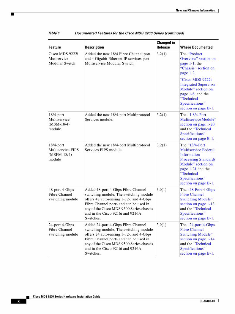
Table 1 Documented Features for the Cisco MDS 9200 Series
Feature DescriptionChanged in Release Where Documented
Cisco MDS Fibre Channel Bladeswitch overview
Description of the Cisco MDS Fibre Channel Bladeswitch for IBM BladeCenter.
3.3(1a) Product Overview chapter.
18/4-port Multiservice (MSM-18/4) module
Added information on IPv6 support. 3.3(1a) The “1 8/4-Port Multiservice Module” section on page 1-20.
18/4-port Multiservice (MSM-18/4) module
Added information on SAN extension support.
3.3(1a) The “1 8/4-Port Multiservice Module” section on page 1-20.
18/4-port Multiservice (MSM-18/4) module
Added the Storage Media Encryption information.
3.2(1) The “1 8/4-Port Multiservice Module” section on page 1-20.
ixCisco MDS 9200 Series Hardware Installation Guide
OL-16188-01
New and Changed Information
Cisco MDS 9222i Mutiservice Modular Switch
Added the new 18/4 Fibre Channel port and 4 Gigabit Ethernet IP services port Multiservice Modular Switch.
3.2(1) The “Product Overview” section on page 1-1, the “Chassis” section on page 1-2,
“Cisco MDS 9222i Integrated Supervisor Module” section on page 1-6, and the “Technical Specifications” section on page B-1.
18/4-port Multiservice (MSM-18/4) module
Added the new 18/4-port Multiprotocol Services module.
3.2(1) The “1 8/4-Port Multiservice Module” section on page 1-20 and the “Technical Specifications” section on page B-1.
18/4-port Multiservice FIPS (MSFM-18/4) module
Added the new 18/4-port Multiprotocol Services FIPS module.
3.2(1) The “18/4-Port Multiservice Federal Information Processing Standards Module” section on page 1-21 and the “Technical Specifications” section on page B-1.
48-port 4-Gbps Fibre Channel switching module
Added 48-port 4-Gbps Fibre Channel switching module. The switching module offers 48 autosensing 1-, 2-, and 4-Gbps Fibre Channel ports and can be used in any of the Cisco MDS 9500 Series chassis and in the Cisco 9216i and 9216A Switches.
3.0(1) The “48-Port 4-Gbps Fibre Channel Switching Module” section on page 1-13 and the “Technical Specifications” section on page B-1.
24-port 4-Gbps Fibre Channel switching module
Added 24-port 4-Gbps Fibre Channel switching module. The switching module offers 24 autosensing 1-, 2-, and 4-Gbps Fibre Channel ports and can be used in any of the Cisco MDS 9500 Series chassis and in the Cisco 9216i and 9216A Switches.
3.0(1) The “24-port 4-Gbps Fibre Channel Switching Module” section on page 1-14 and the “Technical Specifications” section on page B-1.
Table 1 Documented Features for the Cisco MDS 9200 Series (continued)
Feature DescriptionChanged in Release Where Documented
xCisco MDS 9200 Series Hardware Installation Guide
OL-16188-01

New and Changed Information
12-port 4-Gbps Fibre Channel switching module
Added 12-port 4-Gbps Fibre Channel switching module. The switching module can be used in any of the Cisco MDS 9500 Series chassis and in the Cisco MDS 9216i and 9216A Switches.
3.0(1) The “12-port 4-Gbps Fibre Channel Switching Module” section on page 1-14 and the “Technical Specifications” section on page B-1.
4-port 10-Gbps Fibre Channel switching module
Added 4-port 10-Gbps Fibre Channel switching module. The switching module offers four dedicated bandwidth Fibre Channel ports running at 10 Gbps with no oversubscription.
3.0(1) The “4-port 10-Gbps Fibre Channel Switching Module” section on page 1-15 and the “Technical Specifications” section on page B-1.
X2 transceiver Added X2 transceiver. The X2 transceiver is a small form-factor pluggable optimized for 10-Gbps applications.
3.0(1) The “X2 Fibre Channel Transceivers” section on page 1-36 and the “X2 Transceiver Specifications” section on page B-6.
Fibre Channel SFP transceiver
Added 4-Gbps Fibre Channel SFP trans-
ceiver.
3.0(1) The “Fibre Channel SFP Transceivers” section on page 1-36 and the “Cisco Fibre Channel SFP Transceivers” section on page B-10.
Gigabit Ethernet SFP transceiver
Added Gigabit Ethernet SFP transceiver. Not release
specific
The “Supported Transceivers” section on page 1-35 and the “Cisco Gigabit Ethernet Transceivers” section on page B-19.
32-port Fibre Channel Storage Services Module (SSM)
Added 32-port Fibre Channel Storage
Services Module (SSM).
2.0(2b) The “32-Port Fibre Channel Storage Services Module” section on page 1-26.
14/2-port Multiprotocol Services (MPS-14/2) module
Added 14/2-port Multiprotocol Services
module.
2.0(1b) The “14/2-Port Multiprotocol Services Module” section on page 1-22.
Table 1 Documented Features for the Cisco MDS 9200 Series (continued)
Feature DescriptionChanged in Release Where Documented
xiCisco MDS 9200 Series Hardware Installation Guide
OL-xxxxx-xx

New and Changed Information
xiiCisco MDS 9200 Series Hardware Installation Guide
OL-16188-01
Send documenta t ion comments to mds feedba ck -doc@c i sco .com
Preface
This preface describes the audience, organization, and conventions of the Cisco MDS 9200 Series Hardware Installation Guide. It also provides information on how to obtain related documentation.
AudienceTo use this installation guide, you must be familiar with electronic circuitry and wiring practices and preferably be an electronic or electromechanical technician.
OrganizationThis guide is organized as follows:
Chapter Title Description
Chapter 1 Product Overview Provides an overview of the Cisco MDS 9200 Series and its components.
Chapter 2 Installing the Cisco MDS 9200 Series
Describes how to install the Cisco MDS 9200 Series, and how to install modules, power supplies, and fan assemblies.
Chapter 3 Connecting the Cisco MDS 9200 Series
Describes how to connect the Cisco MDS 9200 Series, including the modules.
Appendix A Cabinet and Rack Installation
Provides guidelines for selecting an enclosed cabinet, the procedure for installing a switch using the optional telco and EIA Shelf Bracket Kit.
Appendix B Technical Specifications
Lists specifications for the Cisco MDS 9200 Series switches and components including modules, power, and transceivers.
Appendix C Cable and Port Specifications
Lists cable and port specifications for the Cisco MDS 9200 Series.
Appendix D Site Planning and Maintenance Records
Provides site planning and maintenance records.
xiiiCisco MDS 9200 Series Hardware Installation Guide
OL-16188-01
Send documenta t ion c omments to mds feedba ck -doc@c i sco .com
Preface
ConventionsThis document uses the following conventions for notes, cautions, and safety warnings.
Notes and Cautions contain important information that you should be aware of.
Note Means reader take note. Notes contain helpful suggestions or references to material that are not covered in the publication.
Caution Means reader be careful. You are capable of doing something that might result in equipment damage or loss of data.
Safety warnings appear throughout this publication in procedures that, if performed incorrectly, can cause physical injuries. A warning symbol precedes each warning statement.
Warning This warning symbol means danger. You are in a situation that could cause bodily injury. Before you work on any equipment, be aware of the hazards involved with electrical circuitry and be familiar with standard practices for preventing accidents. To see translations of the warnings that appear in this publication, refer to the Regulatory Compliance and Safety Information document that accompanied this device.
Waarschuwing
Dit waarschuwingssymbool betekent gevaar. U verkeert in een situatie die lichamelijk letsel kan veroorzaken. Voordat u aan enige apparatuur gaat werken, dient u zich bewust te zijn van de bij elektrische schakelingen betrokken risico's en dient u op de hoogte te zijn van standaard maatregelen om ongelukken te voorkomen. Voor vertalingen van de waarschuwingen die in deze publicatie verschijnen, kunt u het document Regulatory Compliance and Safety Information (Informatie over naleving van veiligheids- en andere voorschriften) raadplegen dat bij dit toestel is ingesloten.
Varoitus Tämä varoitusmerkki merkitsee vaaraa. Olet tilanteessa, joka voi johtaa ruumiinvammaan. Ennen kuin työskentelet minkään laitteiston parissa, ota selvää sähkökytkentöihin liittyvistä vaaroista ja tavanomaisista onnettomuuksien ehkäisykeinoista. Tässä julkaisussa esiintyvien varoitusten käännökset löydät laitteen mukana olevasta Regulatory Compliance and Safety Information -kirjasesta (määräysten noudattaminen ja tietoa turvallisuudesta).
Attention Ce symbole d'avertissement indique un danger. Vous vous trouvez dans une situation pouvant causer des blessures ou des dommages corporels. Avant de travailler sur un équipement, soyez conscient des dangers posés par les circuits électriques et familiarisez-vous avec les procédures couramment utilisées pour éviter les accidents. Pour prendre connaissance des traductions d’avertissements figurant dans cette publication, consultez le document Regulatory Compliance and Safety Information (Conformité aux règlements et consignes de sécurité) qui accompagne cet appareil.
xivCisco MDS 9200 Series Hardware Installation Guide
OL-16188-01

Send documenta t ion comments to mds feedba ck -doc@c i sco .com
Preface
Warnung Dieses Warnsymbol bedeutet Gefahr. Sie befinden sich in einer Situation, die zu einer Körperverletzung führen könnte. Bevor Sie mit der Arbeit an irgendeinem Gerät beginnen, seien Sie sich der mit elektrischen Stromkreisen verbundenen Gefahren und der Standardpraktiken zur Vermeidung von Unfällen bewußt. Übersetzungen der in dieser Veröffentlichung enthaltenen Warnhinweise finden Sie im Dokument Regulatory Compliance and Safety Information (Informationen zu behördlichen Vorschriften und Sicherheit), das zusammen mit diesem Gerät geliefert wurde.
Avvertenza Questo simbolo di avvertenza indica un pericolo. La situazione potrebbe causare infortuni alle persone. Prima di lavorare su qualsiasi apparecchiatura, occorre conoscere i pericoli relativi ai circuiti elettrici ed essere al corrente delle pratiche standard per la prevenzione di incidenti. La traduzione delle avvertenze riportate in questa pubblicazione si trova nel documento Regulatory Compliance and Safety Information (Conformità alle norme e informazioni sulla sicurezza) che accompagna questo dispositivo.
Advarsel Dette varselsymbolet betyr fare. Du befinner deg i en situasjon som kan føre til personskade. Før du utfører arbeid på utstyr, må du vare oppmerksom på de faremomentene som elektriske kretser innebærer, samt gjøre deg kjent med vanlig praksis når det gjelder å unngå ulykker. Hvis du vil se oversettelser av de advarslene som finnes i denne publikasjonen, kan du se i dokumentet Regulatory Compliance and Safety Information (Overholdelse av forskrifter og sikkerhetsinformasjon) som ble levert med denne enheten.
Aviso Este símbolo de aviso indica perigo. Encontra-se numa situação que lhe poderá causar danos físicos. Antes de começar a trabalhar com qualquer equipamento, familiarize-se com os perigos relacionados com circuitos eléctricos, e com quaisquer práticas comuns que possam prevenir possíveis acidentes. Para ver as traduções dos avisos que constam desta publicação, consulte o documento Regulatory Compliance and Safety Information (Informação de Segurança e Disposições Reguladoras) que acompanha este dispositivo.
¡Advertencia! Este símbolo de aviso significa peligro. Existe riesgo para su integridad física. Antes de manipular cualquier equipo, considerar los riesgos que entraña la corriente eléctrica y familiarizarse con los procedimientos estándar de prevención de accidentes. Para ver una traducción de las advertencias que aparecen en esta publicación, consultar el documento titulado Regulatory Compliance and Safety Information (Información sobre seguridad y conformidad con las disposiciones reglamentarias) que se acompaña con este dispositivo.
Varning! Denna varningssymbol signalerar fara. Du befinner dig i en situation som kan leda till personskada. Innan du utför arbete på någon utrustning måste du vara medveten om farorna med elkretsar och känna till vanligt förfarande för att förebygga skador. Se förklaringar av de varningar som förkommer i denna publikation i dokumentet Regulatory Compliance and Safety Information (Efterrättelse av föreskrifter och säkerhetsinformation), vilket medföljer denna anordning.
xvCisco MDS 9200 Series Hardware Installation Guide
OL-xxxxx-xx
Send documenta t ion c omments to mds feedba ck -doc@c i sco .com
PrefaceRelated Documentation
Related DocumentationThe documentation set for the Cisco MDS 9000 Family includes the following documents. The documentation set for the Cisco MDS 9000 Family includes the following documents. To find a document online, use the Cisco MDS SAN-OS Documentation Locator at:
http://www.cisco.com/en/US/products/ps5989/products_documentation_roadmap09186a00804500c1.html.
Release Notes• Cisco MDS 9000 Family Release Notes for Cisco MDS SAN-OS Releases
• Cisco MDS 9000 Family Release Notes for Storage Services Interface Images
• Cisco MDS 9000 Family Release Notes for Cisco MDS 9000 EPLD Images
Compatibility Information• Cisco MDS 9000 SAN-OS Hardware and Software Compatibility Information
• Cisco MDS 9000 Family Interoperability Support Matrix
• Cisco MDS Storage Services Module Interoperability Support Matrix
• Cisco MDS SAN-OS Release Compatibility Matrix for Storage Service Interface Images
Regulatory Compliance and Safety Information• Regulatory Compliance and Safety Information for the Cisco MDS 9000 Family
Hardware Installation• Cisco MDS 9124 Multilayer Fabric Switch Quick Start Guide
• Cisco MDS 9500 Series Hardware Installation Guide
• Cisco MDS 9200 Series Hardware Installation Guide
• Cisco MDS 9100 Series Hardware Installation Guide
Cisco Fabric Manager• Cisco MDS 9000 Family Fabric Manager Quick Configuration Guide
• Cisco MDS 9000 Family Fabric Manager Configuration Guide
• Cisco MDS 9000 Family Fabric Manager Database Schema
• Cisco MDS 9000 Family Data Mobility Manager Configuration Guide
xviCisco MDS 9200 Series Hardware Installation Guide
OL-16188-01
Send documenta t ion comments to mds feedba ck -doc@c i sco .com
PrefaceRelated Documentation
Command-Line Interface• Cisco MDS 9000 Family Software Upgrade and Downgrade Guide
• Cisco MDS 9000 Family Storage Services Module Software Installation and Upgrade Guide
• Cisco MDS 9000 Family CLI Quick Configuration Guide
• Cisco MDS 9000 Family CLI Configuration Guide
• Cisco MDS 9000 Family Command Reference
Intelligent Storage Networking Services Configuration Guides• Cisco MDS 9000 Family Data Mobility Manager Configuration Guide
• Cisco MDS 9000 Family Storage Media Encryption Configuration Guide
• Cisco MDS 9000 Family Secure Erase Configuration Guide - For Cisco MDS 9500 and 9200 Series
Troubleshooting and Reference• Cisco MDS 9000 Family Troubleshooting Guide
• Cisco MDS 9000 Family MIB Quick Reference
• Cisco MDS 9000 Family SMI-S Programming Reference
• Cisco MDS 9000 Family System Messages Reference
Installation and Configuration Note• Cisco MDS 9000 Family SSM Configuration Note
• Cisco MDS 9000 Family Port Analyzer Adapter Installation and Configuration Note
• Cisco 10-Gigabit X2 Transceiver Module Installation Note
• Cisco MDS 9000 Family CWDM SFP Installation Note
• Cisco MDS 9000 Family CWDM Passive Optical System Installation Note
xviiCisco MDS 9200 Series Hardware Installation Guide
OL-xxxxx-xx

Send documenta t ion c omments to mds feedba ck -doc@c i sco .com
PrefaceObtaining Documentation, Obtaining Support, and Security Guidelines
Obtaining Documentation, Obtaining Support, and Security Guidelines
For information on obtaining documentation, submitting a service request, and gathering additional information, see the monthly What’s New in Cisco Product Documentation, which also lists all new and revised Cisco technical documentation, at:
http://www.cisco.com/en/US/docs/general/whatsnew/whatsnew.html
Subscribe to the What’s New in Cisco Product Documentation as a Really Simple Syndication (RSS) feed and set content to be delivered directly to your desktop using a reader application. The RSS feeds are a free service and Cisco currently supports RSS version 2.0.
xviiiCisco MDS 9200 Series Hardware Installation Guide
OL-16188-01
Send documenta t ion comments to mds feedba ck -doc@c i sco .com
COL-16188-01
C H A P T E R 1
Product OverviewThe Cisco MDS 9200 Series of multilayer modular fabric switches supports storage area network (SAN) applications. The Cisco MDS 9200 Series switches provide scalability, multitransport capability, security, and manageability to enterprise SANs. The Cisco MDS 9200 Series shares a consistent architecture with the Cisco MDS 9500 Series of multilayer directors, making it an intelligent and flexible fabric switch series. The Cisco MDS 9200 Series includes the Cisco MDS 9222i Multiservice Modular Switch, the Cisco MDS 9216i Multilayer Fabric Switch, and the Cisco MDS 9216A Multilayer Fabric Switch.
The Cisco MDS 9200 Series provides the following features:
• An interface module providing local and remote management interfaces for the supervisor module.
• A spare slot for an optional hot-swappable switching or services module.
• Redundant and hot-swappable power supplies and fan modules.
• Power and cooling management and environmental monitoring.
• Switch module port interfaces that support field-replaceable, hot-swappable X2 transceivers.
• Switch module port interfaces that support field-replaceable, hot-swappable small form-factor pluggable (SFP) transceivers.
• Nondisruptive code load and activation.
• Redundant and self-monitoring system clocks.
The Cisco MDS 9222i Multiservice Modular Switch provides an 18-port Fibre Channel switching and 4-port Gigabit Ethernet IP services module, and a modular expansion slot to host Cisco MDS 9000 Family Switching and Services modules.
The Cisco 9216i Switch includes a nonremovable supervisor module with an integrated 14-port Fibre Channel and 2-port Gigabit Ethernet switching module. The integrated supervisor module supports IP services on the 2 Gigabit Ethernet ports. It also provides switching and local and remote management.
The Cisco 9216A Switch includes a nonremovable supervisor module with an integrated 16-port Fibre Channel switching module. The integrated supervisor module provides switching and local and remote management.
The Cisco MDS 9200 Series enhances the Cisco MDS 9216 Switch with a flexible backplane that is designed to meet the requirements of future modules in the Cisco MDS 9000 Family, while maintaining backward compatibility with all existing modules. The Cisco MDS 9200 Series is also compatible with all existing Cisco MDS 9216 power supplies and fan trays, and provides a COM1 port interface that is compatible with a standard RJ-45 to DB-9 adapter.
For information on how to configure the Cisco MDS 9200 Series, see the Cisco MDS 9000 Family CLI Configuration Guide and the Cisco MDS 9000 Family Fabric Manager Configuration Guide.
1-1isco MDS 9200 Series Hardware Installation Guide
Chapter 1 Product Overview Chassis
Note The Cisco MDS 9200 Series requires Cisco MDS SAN-OS Release 2.0(x) or later. The Cisco MDS 9222i Switch requires MDS SAN-OS Release 3.2(1)
The following hot-swappable, field-replaceable modules are supported by the Cisco MDS 9200 Series:
• 48-port 4-Gbps Fibre Channel switching module (DS-X9148)
• 24-port 4-Gbps Fibre Channel switching module (DS-X9124)
• 12-port 4-Gbps Fibre Channel switching module (DS-X9112)
• 4-port 10-Gbps Fibre Channel switching module (DS-X9704)
• 32-port 2-Gbps Fibre Channel switching module (DS-X9032)
• 16-port 2-Gbps Fibre Channel switching module (DS-X9016)
• 18/4-port Multiservice (MSM-18/4) module (DS-X9304-18K9)
• 18/4-port Multiservice FIPS (MSFM-18/4) module (DS-X9304-18FK9
• 14/2-port Multiprotocol Services (MPS-14/2) module (DS-X9302-14K9)
• 8-port IP Storage Services (IPS-8) module (DS-X9308-SMIP)
• 4-port IP Storage Services (IPS-4) module (DS-X9304-SMIP)
• Storage Services Module (SSM) (DS-X9032-SSM)
• Advanced Services Module (ASM) (DS-X9032-SMV)
• Caching Services Module (CSM) (DS-X9560-SMC)
This chapter includes the following sections:
• Chassis, page 1-2
• Cisco MDS Fibre Channel Bladeswitch for IBM Blade Center, page 1-5
• Integrated Supervisor Modules, page 1-5
• Interface Modules, page 1-10
• Cisco MDS 9000 Family Module Compatibility, page 1-12
• Switching Modules, page 1-12
• Services Modules, page 1-20
• Fan Module, page 1-35
• Supported Transceivers, page 1-35
ChassisThe Cisco MDS 9200 Series switches have a two-slot chassis. The Cisco MDS 9222i (see Figure 1-1) has a nonremovable supervisor module (in slot 1) with an integrated 18-port Fibre Channel switching and 4-port Gigabit Ethernet IP services module, and a modular expansion slot to host Cisco MDS 9000 Family Switching and Services modules. See the “Cisco MDS 9222i Integrated Supervisor Module” section on page 1-6.
The Cisco MDS 9216i (see Figure 1-2) has a nonremovable supervisor module (in slot 1) with an integrated 14-port Fibre Channel and 2-port Gigabit Ethernet switching module. See the “Cisco MDS 9216i Integrated Supervisor Module” section on page 1-6.
1-2Cisco MDS 9200 Series Hardware Installation Guide
OL-16188-01

Chapter 1 Product Overview Chassis
The Cisco MDS 9216A (see Figure 1-3) has a nonremovable supervisor module (in slot 1) with an integrated 16-port Fibre Channel switching module. See the “Cisco MDS 9216A Integrated Supervisor Module” section on page 1-7.
Figure 1-1 Cisco MDS 9222i Chassis
184704
1
3
42
1 Fan module 3 Supervisor module with integrated 18-port Fibre Channel switching and 4-port Gigabit Ethernet IP Storage Services module
2 Switching module or the services module 4 Interface module
1-3Cisco MDS 9200 Series Hardware Installation Guide
OL-16188-01
Chapter 1 Product Overview Chassis
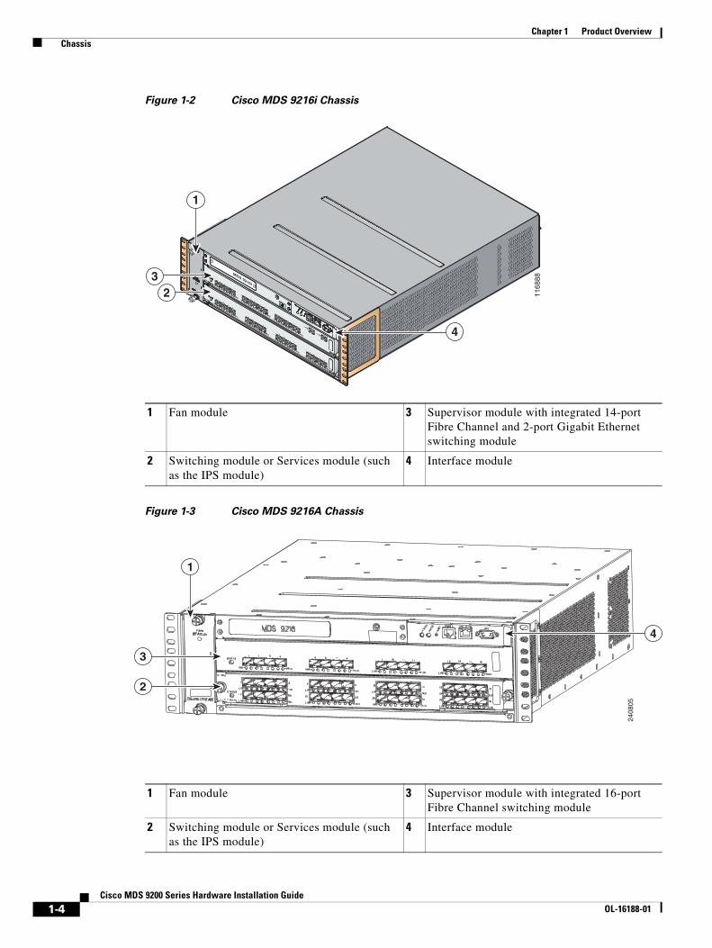
Figure 1-2 Cisco MDS 9216i Chassis
Figure 1-3 Cisco MDS 9216A Chassis
MDS 9216i
GE1
LINK
GE2
LINK
5
6
7
8
9
10
11
12
13
14
1
2
3
4
11
68
88
4
23
1
1 Fan module 3 Supervisor module with integrated 14-port Fibre Channel and 2-port Gigabit Ethernet switching module
2 Switching module or Services module (such as the IPS module)
4 Interface module
1 Fan module 3 Supervisor module with integrated 16-port Fibre Channel switching module
2 Switching module or Services module (such as the IPS module)
4 Interface module
2408
05
1
4
3
2
1-4Cisco MDS 9200 Series Hardware Installation Guide
OL-16188-01
Chapter 1 Product Overview Cisco MDS Fibre Channel Bladeswitch for IBM Blade Center
The Cisco MDS 9200 Series supports the following additional modules:
• The nonremovable interface module (located above the integrated supervisor module), provides the console port (COM1 port) and the MGMT 10/100 Ethernet port for the integrated supervisor module. See the “Interface Modules” section on page 1-10.
• An optional module in the open slot (slot 2).
• Two power supplies that are redundant by default and can be configured to be combined if desired.
• A hot-swappable fan module with four fans provides redundancy. See the “Fan Module” section on page 1-35.
Cisco MDS Fibre Channel Bladeswitch for IBM Blade CenterThe Cisco MDS Fibre Channel Bladeswitch for IBM BladeCenter is designed for IBM BladeCenter environments. The Cisco MDS Fibre Channel Bladeswitch is based on the Cisco MDS 9000 Family SAN switching technology, which integrates the Cisco MDS 9000 Family of switches and directors into a blade-switch architecture. The advanced architecture of the Cisco MDS Fibre Channel Bladeswitch for IBM BladeCenter, along with 4-GB technology, provides outstanding performance between Bladeswitches and the rest of the Fibre Channel infrastructure.
The Cisco MDS Fibre Channel Bladeswitch for IBM BladeCenter provides 4-GB Fibre Channel performance to blade-server switching. It also provides network intelligence features such as virtual SANs (VSANs), quality of service (QoS), and N-port interface virtualization (NPIV). It also offers nondisruptive software upgrades and on-demand port activation and is the most complete embedded Fibre Channel switching available for the IBM BladeCenter, BladeCenter-T, and BladeCenter-H platforms.
The Cisco MDS Fibre Channel Bladeswitch for IBM BladeCenter provides up to 20 nonblocking 1-, 2-, and 4-GB Fibre Channel ports that are available in two configurations: 7 internal ports and 3 external ports, or 14 internal ports and 6 external ports. Each port provides line-rate performance up to 4-GB without any performance loss for integrated features such as VSANs, QoS, or Network Address Translation (NAT). The Cisco MDS Fibre Channel Bladeswitch for IBM BladeCenter supports up to 16 VSANs per blade switch.
Each external port on the Cisco MDS FC Bladeswitch for IBM BladeCenter also provides line-rate performance up to 4-GB for Inter-Switch Links (ISLs) or additional device connectivity such as storage or host bus adapters (HBAs).
The Cisco SAN-OS software provides role-based access control (RBAC) for management access of the Cisco Fibre Channel Bladeswitch for IBM BladeCenter command-line interface (CLI) and Simple Network Management Protocol (SNMP). For more information, see the Cisco 9000 Family Command Reference.
Integrated Supervisor ModulesThe Cisco MDS 9200 Series switches have nonremovable integrated supervisor modules in each chassis. These modules include the following:
• Cisco MDS 9222i Integrated Supervisor Module, page 1-6
• Cisco MDS 9216i Integrated Supervisor Module, page 1-6
• Cisco MDS 9216A Integrated Supervisor Module, page 1-7
1-5Cisco MDS 9200 Series Hardware Installation Guide
OL-16188-01
Chapter 1 Product Overview Integrated Supervisor Modules
Cisco MDS 9222i Integrated Supervisor ModuleThe nonremovable Cisco MDS 9222i integrated supervisor module provides the control and management functions of the Cisco MDS 9222i Switch, and it includes an integrated 18-port Fibre Channel switching and 4-port Gigabit Ethernet IP services module. The Cisco MDS 9222i integrated supervisor module provides multiple communication and control paths to avoid a single point of failure.
Note For description of the integrated 18/4-port Multiservice and the 18/4-port Multiservice FIPS module and their capabilities, see the “1 8/4-Port Multiservice Module” section on page 1-20 and the “18/4-Port Multiservice Federal Information Processing Standards Module” section on page 1-21.
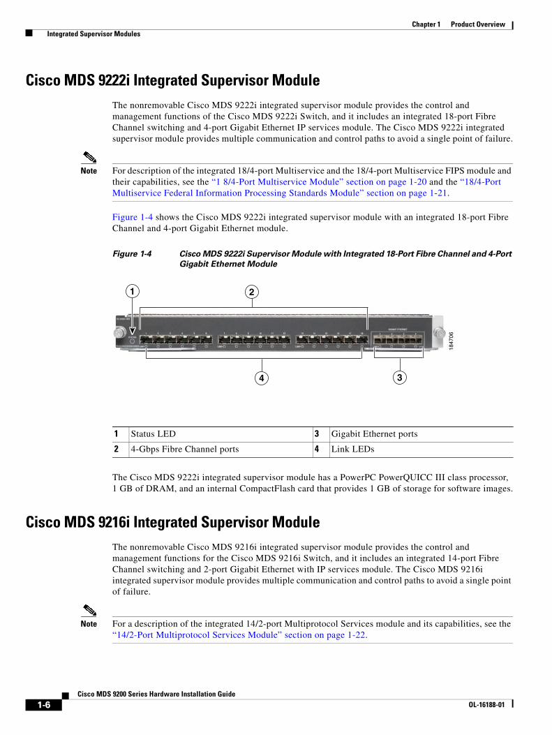
Figure 1-4 shows the Cisco MDS 9222i integrated supervisor module with an integrated 18-port Fibre Channel and 4-port Gigabit Ethernet module.
Figure 1-4 Cisco MDS 9222i Supervisor Module with Integrated 18-Port Fibre Channel and 4-Port
Gigabit Ethernet Module
The Cisco MDS 9222i integrated supervisor module has a PowerPC PowerQUICC III class processor, 1 GB of DRAM, and an internal CompactFlash card that provides 1 GB of storage for software images.
Cisco MDS 9216i Integrated Supervisor ModuleThe nonremovable Cisco MDS 9216i integrated supervisor module provides the control and management functions for the Cisco MDS 9216i Switch, and it includes an integrated 14-port Fibre Channel switching and 2-port Gigabit Ethernet with IP services module. The Cisco MDS 9216i integrated supervisor module provides multiple communication and control paths to avoid a single point of failure.
Note For a description of the integrated 14/2-port Multiprotocol Services module and its capabilities, see the “14/2-Port Multiprotocol Services Module” section on page 1-22.
1847
06
1 2
4 3
1 Status LED 3 Gigabit Ethernet ports
2 4-Gbps Fibre Channel ports 4 Link LEDs
1-6Cisco MDS 9200 Series Hardware Installation Guide
OL-16188-01
Chapter 1 Product Overview Integrated Supervisor Modules
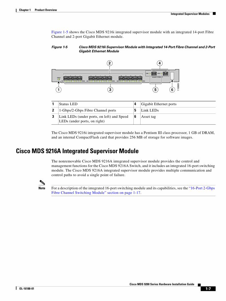
Figure 1-5 shows the Cisco MDS 9216i integrated supervisor module with an integrated 14-port Fibre Channel and 2-port Gigabit Ethernet module.
Figure 1-5 Cisco MDS 9216i Supervisor Module with Integrated 14-Port Fibre Channel and 2-Port
Gigabit Ethernet Module
The Cisco MDS 9216i integrated supervisor module has a Pentium III class processor, 1 GB of DRAM, and an internal CompactFlash card that provides 256 MB of storage for software images.
Cisco MDS 9216A Integrated Supervisor ModuleThe nonremovable Cisco MDS 9216A integrated supervisor module provides the control and management functions for the Cisco MDS 9216A Switch, and it includes an integrated 16-port switching module. The Cisco MDS 9216A integrated supervisor module provides multiple communication and control paths to avoid a single point of failure.
Note For a description of the integrated 16-port switching module and its capabilities, see the “16-Port 2-Gbps Fibre Channel Switching Module” section on page 1-17.
1 Status LED 4 Gigabit Ethernet ports
2 1-Gbps/2-Gbps Fibre Channel ports 5 Link LEDs
3 Link LEDs (under ports, on left) and Speed LEDs (under ports, on right)
6 Asset tag
—SPEED LINK—
LINK-
—SPEEDLINK—
STATUS
1 5 6 7 8 9
LINK— —SPEED
10 11 12 13 142 3 4
1 2
LINK-
GIGABIT E THERNET
1168
89
1 6
2 4
3 5
1-7Cisco MDS 9200 Series Hardware Installation Guide
OL-16188-01

Chapter 1 Product Overview Integrated Supervisor Modules
Figure 1-6 shows the Cisco MDS 9216A supervisor module with an integrated 16-port Switching module.
Figure 1-6 Cisco MDS 9216A Supervisor Module with Integrated 16-Port Switching Module
The Cisco MDS 9216A integrated supervisor module has a Pentium III class processor, 1 GB of DRAM, and an internal CompactFlash card that provides 256 MB of storage for software images.
1 Status LED 3 Link LEDs (under ports, on left) and Speed LEDs (under ports, on right)
2 1-Gbps/2-Gbps Fibre Channel ports 4 Asset tag
9167
0
1 43
LINK- -SPEED LINK- -SPEED LINK- -SPEED LINK- -SPEED
1 2 3 4 1 2 3 4 1 2 3 4 1 2 3 4
2
1-8Cisco MDS 9200 Series Hardware Installation Guide
OL-16188-01

Chapter 1 Product Overview Integrated Supervisor Modules
LEDs on the Cisco MDS 9200 Series Integrated Supervisor ModulesTable 1-1 describes the LEDs for the Cisco MDS 9200 Series integrated supervisor modules.
Table 1-1 LEDs for the Cisco MDS 9200 Series Integrated Supervisor Modules
LED Status Description
Status Green All diagnostics pass. The module is operational (normal initialization sequence).
Orange One of the following occurs or occurred:
• The module is booting or running diagnostics (normal initialization sequence).
• The inlet air temperature of the system exceeded the maximum system operating temperature limit (a minor environmental warning). To ensure maximum product life, you should immediately correct the environmental temperature and restore the system to normal operation.
Red One of the following occurred:
• The diagnostic test failed. The module is not operational because a fault occurred during the initialization sequence.
• The inlet air temperature of the system exceeded the safe operating temperature limits of the card (a major environmental warning). The card shut down to prevent permanent damage. The system will be shut down after two minutes if this condition is not cleared.
Speed1
1. The Speed LEDs are available only on Cisco MDS 9216i and Cisco MDS 9216A Supervisor Modules.
On 2-Gbps mode.
Off 1-Gbps mode.
Link Solid green Link is up.
Flashing green
Link is up (beacon used to identify port).
Solid yellow
Link is disabled by software.
Flashing yellow
A fault condition exists.
Off No link.
1-9Cisco MDS 9200 Series Hardware Installation Guide
OL-16188-01

Chapter 1 Product Overview Interface Modules
Interface ModulesThe nonremovable interface module is located above slot 1 (see Figure 1-7) and is identical for all Cisco MDS 9200 Series switches. It provides the following local and remote management interfaces:
• RS-232 (EIA/TIA-232) console port with an RJ-45 connection that you can use to:
– Configure the switch from the CLI.
– Monitor network statistics and errors.
– Configure SNMP agent parameters.
• MGMT 10/100 Ethernet port with an RJ-45 connection that provides network management capabilities.
• RS-232 COM1 port with a DB-9 connector that can be attached to a modem.
Figure 1-7 Nonremoveable Interface Module of the Cisco MDS 9200 Series
The clock module is also part of the interface module.
Note The system clocks in the Cisco MDS 9200 Series have a field-measured mean time between failures (MTBF) of approximately 3.2 million hours or 365 years. In the event of a clock module failure, the system generates an error message and a switchover from one clock module to the other occurs, causing the system to reset automatically.
1 ESD socket (for ESD strap) 6 MGMT 10/100 Ethernet port (with integrated Link and Activity LEDs)
2 Grounding pad (beneath tape) 7 COM1 port
3 Status and System LEDs 8 Asset tag
4 Reset button 9 Interface module
5 Console port
STAT
US
SYST
EM
RES
ET CONSOLE MGMT 10/100
MDS 9216i 9
31 5 6
42
1168
90
COM1
7 8
1-10Cisco MDS 9200 Series Hardware Installation Guide
OL-16188-01
Chapter 1 Product Overview Interface Modules
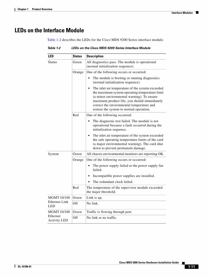
LEDs on the Interface ModuleTable 1-2 describes the LEDs for the Cisco MDS 9200 Series interface module.
Table 1-2 LEDs on the Cisco MDS 9200 Series Interface Module
LED Status Description
Status Green All diagnostics pass. The module is operational (normal initialization sequence).
Orange One of the following occurs or occurred:
• The module is booting or running diagnostics (normal initialization sequence).
• The inlet air temperature of the system exceeded the maximum system operating temperature limit (a minor environmental warning). To ensure maximum product life, you should immediately correct the environmental temperature and restore the system to normal operation.
Red One of the following occurred:
• The diagnostic test failed. The module is not operational because a fault occurred during the initialization sequence.
• The inlet air temperature of the system exceeded the safe operating temperature limits of the card (a major environmental warning). The card shut down to prevent permanent damage.
System Green All chassis environmental monitors are reporting OK.
Orange One of the following occurs or occurred:
• The power supply failed or the power supply fan failed.
• Incompatible power supplies are installed.
• The redundant clock failed.
Red The temperature of the supervisor module exceeded the major threshold.
MGMT 10/100 Ethernet Link LED
Green Link is up.
Off No link.
MGMT 10/100 Ethernet Activity LED
Green Traffic is flowing through port.
Off No link or no traffic.
1-11Cisco MDS 9200 Series Hardware Installation Guide
OL-16188-01

Chapter 1 Product Overview Cisco MDS 9000 Family Module Compatibility
Cisco MDS 9000 Family Module CompatibilityTable 1-3 lists the hardware modules available and the chassis compatibility associated with them.
Switching ModulesThe Cisco MDS 9200 Series supports the following hot-swappable Fibre Channel switching modules:
• Generation 2 Modules
– 48-Port 4-Gbps Fibre Channel Switching Module
– 24-port 4-Gbps Fibre Channel Switching Module
– 12-port 4-Gbps Fibre Channel Switching Module
– 4-port 10-Gbps Fibre Channel Switching Module
• Generation 1 Modules
– 32-Port 2-Gbps Fibre Channel Switching Module
– 16-Port 2-Gbps Fibre Channel Switching Module
The Cisco MDS 9200 Series supports one hot-swappable switching or services module in addition to the integrated module that is part of the supervisor module.
Table 1-3 MDS 9000 Modules and Platform Compatibility Matrix
Module 9513 9509 9506 9222i 9216A 9216i 9216
Supervisor-2 module X X X
Supervisor-1 module X X
48-port 4-Gbps Fibre Channel switching module X X X X X X
24-port 4-Gbps Fibre Channel switching module X X X X X X
12-port 4-Gbps Fibre Channel switching module X X X X X X
4-port 10-Gbps Fibre Channel switching module X X X X X X
32-port 1-Gbps/2-Gbps Fibre Channel module X X X X X X
16-port 1-Gbps/2-Gbps Fibre Channel module X X X X X X
8-port Gigabit Ethernet IP Storage Services module X X X X X X X
4-port Gigabit Ethernet IP Storage Services module X X X X X X
32-port Fibre Channel Advanced Services Module (ASM) X X X X X
32-port 1-Gbps/2-Gbps Fibre Channel Storage Services Module (SSM)
X X X X X X X
Caching Services Module (CSM) X X X X X
18-port Fibre Channel /4-port Gigabit Ethernet Multiservice (MSM-18/4) module
X X X X X X
18-port Fibre Channel /4-port Gigabit Ethernet Multiservice FIPS (MSFM-18/4) module
X X X X X X
14-port Fibre Channel/2-port Gigabit Ethernet Multiprotocol Services (MPS-14/2) module
X X X X X X
1-12Cisco MDS 9200 Series Hardware Installation Guide
OL-16188-01
Chapter 1 Product Overview Switching Modules
The Fibre Channel switching modules provide system-wide power management and autonegotiation, which allows ports to negotiate for speed at the other end of the link. Each module has temperature sensors and an EEPROM that stores serial number and model number information.
The Fibre Channel port interfaces support hot-swappable Fibre Channel SFP transceivers that can be short wavelength (SWL) or long wavelength (LWL). The port interfaces also support coarse wavelength-division multiplexing (CWDM) SFP transceivers, which can be used for extended long wavelength (ELWL) transmission or for CWDM. See the “Supported Transceivers” section on page 1-35.
Note The internal bootflash installed on the modules are not field-replaceable units. Do not remove or replace internal bootflash on the modules. Modifying the factory-installed bootflash is not supported.
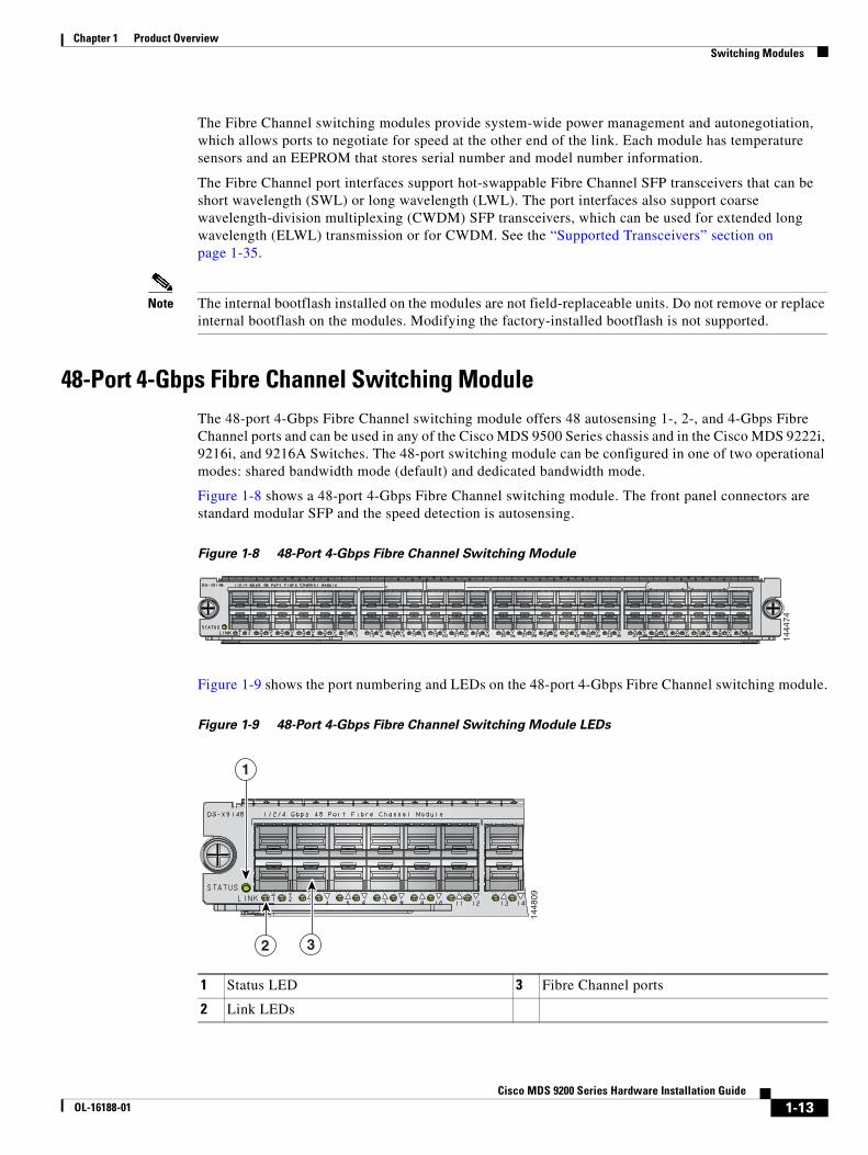
48-Port 4-Gbps Fibre Channel Switching ModuleThe 48-port 4-Gbps Fibre Channel switching module offers 48 autosensing 1-, 2-, and 4-Gbps Fibre Channel ports and can be used in any of the Cisco MDS 9500 Series chassis and in the Cisco MDS 9222i, 9216i, and 9216A Switches. The 48-port switching module can be configured in one of two operational modes: shared bandwidth mode (default) and dedicated bandwidth mode.
Figure 1-8 shows a 48-port 4-Gbps Fibre Channel switching module. The front panel connectors are standard modular SFP and the speed detection is autosensing.
Figure 1-8 48-Port 4-Gbps Fibre Channel Switching Module
Figure 1-9 shows the port numbering and LEDs on the 48-port 4-Gbps Fibre Channel switching module.
Figure 1-9 48-Port 4-Gbps Fibre Channel Switching Module LEDs
1444
74
1 Status LED 3 Fibre Channel ports
2 Link LEDs
1448
09
1
2 3
1-13Cisco MDS 9200 Series Hardware Installation Guide
OL-16188-01
Chapter 1 Product Overview Switching Modules
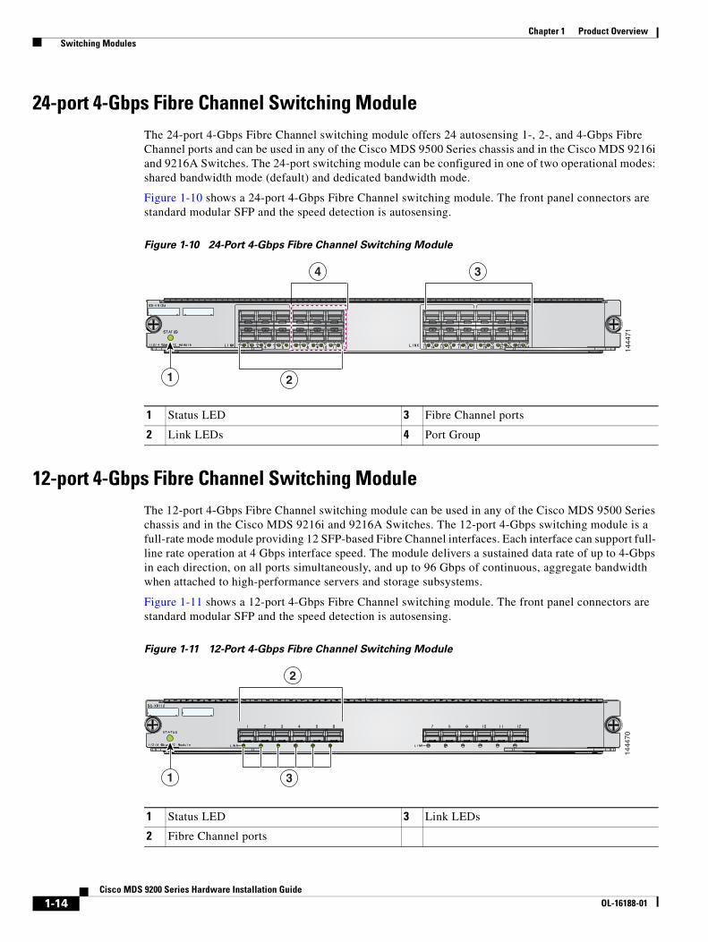
24-port 4-Gbps Fibre Channel Switching ModuleThe 24-port 4-Gbps Fibre Channel switching module offers 24 autosensing 1-, 2-, and 4-Gbps Fibre Channel ports and can be used in any of the Cisco MDS 9500 Series chassis and in the Cisco MDS 9216i and 9216A Switches. The 24-port switching module can be configured in one of two operational modes: shared bandwidth mode (default) and dedicated bandwidth mode.
Figure 1-10 shows a 24-port 4-Gbps Fibre Channel switching module. The front panel connectors are standard modular SFP and the speed detection is autosensing.
Figure 1-10 24-Port 4-Gbps Fibre Channel Switching Module
12-port 4-Gbps Fibre Channel Switching ModuleThe 12-port 4-Gbps Fibre Channel switching module can be used in any of the Cisco MDS 9500 Series chassis and in the Cisco MDS 9216i and 9216A Switches. The 12-port 4-Gbps switching module is a full-rate mode module providing 12 SFP-based Fibre Channel interfaces. Each interface can support full- line rate operation at 4 Gbps interface speed. The module delivers a sustained data rate of up to 4-Gbps in each direction, on all ports simultaneously, and up to 96 Gbps of continuous, aggregate bandwidth when attached to high-performance servers and storage subsystems.
Figure 1-11 shows a 12-port 4-Gbps Fibre Channel switching module. The front panel connectors are standard modular SFP and the speed detection is autosensing.
Figure 1-11 12-Port 4-Gbps Fibre Channel Switching Module
1 Status LED 3 Fibre Channel ports
2 Link LEDs 4 Port Group
1444
71
2
34
1
1 Status LED 3 Link LEDs
2 Fibre Channel ports
1444
70
3
2
1
1-14Cisco MDS 9200 Series Hardware Installation Guide
OL-16188-01
Chapter 1 Product Overview Switching Modules
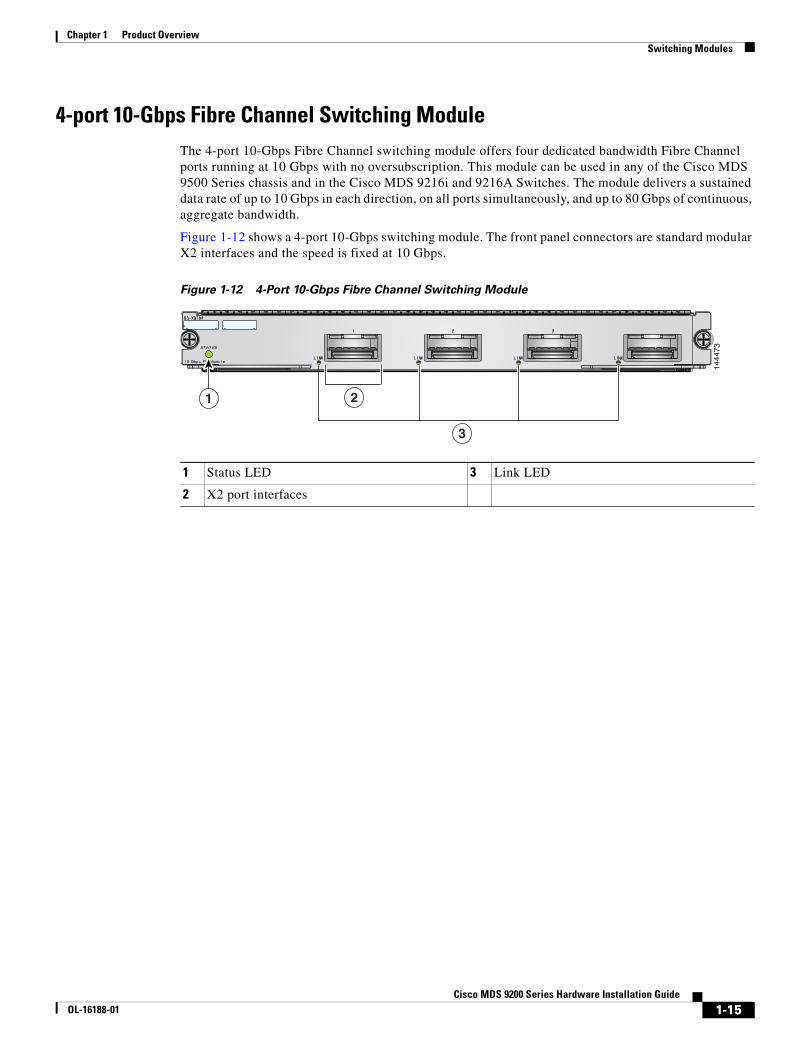
4-port 10-Gbps Fibre Channel Switching ModuleThe 4-port 10-Gbps Fibre Channel switching module offers four dedicated bandwidth Fibre Channel ports running at 10 Gbps with no oversubscription. This module can be used in any of the Cisco MDS 9500 Series chassis and in the Cisco MDS 9216i and 9216A Switches. The module delivers a sustained data rate of up to 10 Gbps in each direction, on all ports simultaneously, and up to 80 Gbps of continuous, aggregate bandwidth.
Figure 1-12 shows a 4-port 10-Gbps switching module. The front panel connectors are standard modular X2 interfaces and the speed is fixed at 10 Gbps.
Figure 1-12 4-Port 10-Gbps Fibre Channel Switching Module
1 Status LED 3 Link LED
2 X2 port interfaces
1444
73
2
3
1
1-15Cisco MDS 9200 Series Hardware Installation Guide
OL-16188-01
Chapter 1 Product Overview Switching Modules
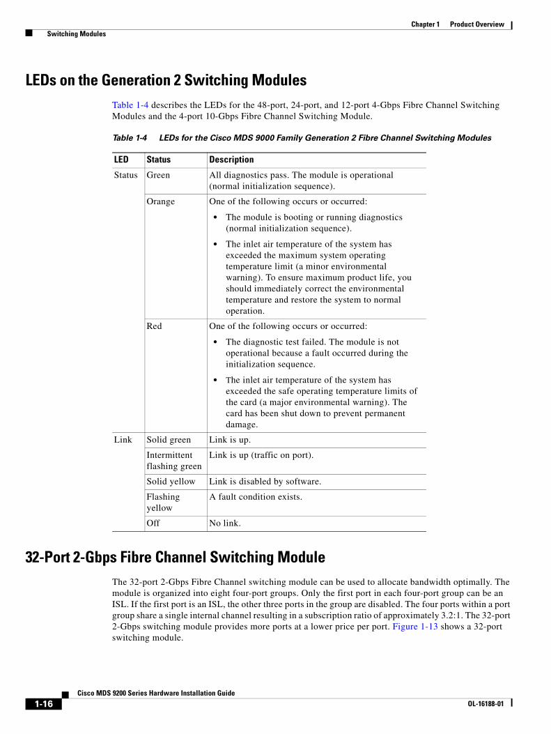
LEDs on the Generation 2 Switching ModulesTable 1-4 describes the LEDs for the 48-port, 24-port, and 12-port 4-Gbps Fibre Channel Switching Modules and the 4-port 10-Gbps Fibre Channel Switching Module.
32-Port 2-Gbps Fibre Channel Switching ModuleThe 32-port 2-Gbps Fibre Channel switching module can be used to allocate bandwidth optimally. The module is organized into eight four-port groups. Only the first port in each four-port group can be an ISL. If the first port is an ISL, the other three ports in the group are disabled. The four ports within a port group share a single internal channel resulting in a subscription ratio of approximately 3.2:1. The 32-port 2-Gbps switching module provides more ports at a lower price per port. Figure 1-13 shows a 32-port switching module.
Table 1-4 LEDs for the Cisco MDS 9000 Family Generation 2 Fibre Channel Switching Modules
LED Status Description
Status Green All diagnostics pass. The module is operational (normal initialization sequence).
Orange One of the following occurs or occurred:
• The module is booting or running diagnostics (normal initialization sequence).
• The inlet air temperature of the system has exceeded the maximum system operating temperature limit (a minor environmental warning). To ensure maximum product life, you should immediately correct the environmental temperature and restore the system to normal operation.
Red One of the following occurs or occurred:
• The diagnostic test failed. The module is not operational because a fault occurred during the initialization sequence.
• The inlet air temperature of the system has exceeded the safe operating temperature limits of the card (a major environmental warning). The card has been shut down to prevent permanent damage.
Link Solid green Link is up.
Intermittent flashing green
Link is up (traffic on port).
Solid yellow Link is disabled by software.
Flashing yellow
A fault condition exists.
Off No link.
1-16Cisco MDS 9200 Series Hardware Installation Guide
OL-16188-01
Chapter 1 Product Overview Switching Modules
Tip For a full 2-Gbps bandwidth between two hosts, connect one host to the first port group and the second host to the second port group.
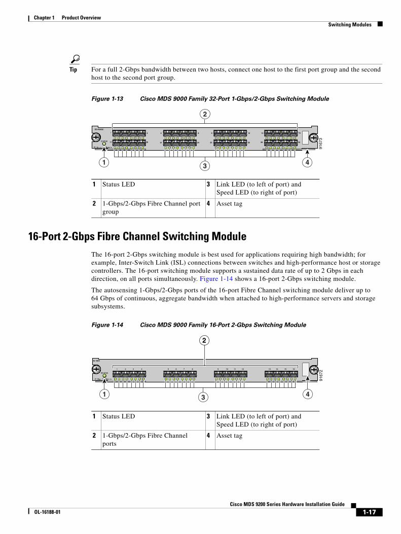
Figure 1-13 Cisco MDS 9000 Family 32-Port 1-Gbps/2-Gbps Switching Module
16-Port 2-Gbps Fibre Channel Switching ModuleThe 16-port 2-Gbps switching module is best used for applications requiring high bandwidth; for example, Inter-Switch Link (ISL) connections between switches and high-performance host or storage controllers. The 16-port switching module supports a sustained data rate of up to 2 Gbps in each direction, on all ports simultaneously. Figure 1-14 shows a 16-port 2-Gbps switching module.
The autosensing 1-Gbps/2-Gbps ports of the 16-port Fibre Channel switching module deliver up to 64 Gbps of continuous, aggregate bandwidth when attached to high-performance servers and storage subsystems.
Figure 1-14 Cisco MDS 9000 Family 16-Port 2-Gbps Switching Module
1 Status LED 3 Link LED (to left of port) and Speed LED (to right of port)
2 1-Gbps/2-Gbps Fibre Channel port group
4 Asset tag
9167
3
2
1 43
17 20
4
DS-X9032
5
21 24
8 9
25 28
12 13
29 32
16
1 Status LED 3 Link LED (to left of port) and Speed LED (to right of port)
2 1-Gbps/2-Gbps Fibre Channel ports
4 Asset tag
9167
2
43
1 2 3 4 5 6 7 8 9 10 11 12 13 14 15 16
2
1
1-17Cisco MDS 9200 Series Hardware Installation Guide
OL-16188-01

Chapter 1 Product Overview Switching Modules
Switching Module FeaturesEach switching module draws its power from the 42 V supplied on the backplane with local DC/DC power converters and regulators.
The control processor on the switching module provides power-on, offline, and online diagnostics. The control processor can be used to configure devices on the switching module and to gather statistical data from each port.
The control processor can determine which slot it is plugged into, and it can monitor its DC/DC power source and temperature. The control processor signals the supervisor module and displays an alarm on its front panel when a problem is detected.
The front panel on the switching module provides basic status information, such as power-on, self-test running, self-test passed, alarm, and ready.
The binary image for the switching module is downloaded from the supervisor module. Prior to the image download, the control processor on the switching module runs from code stored on its local CompactFlash card.
Note Routine software downloads are not required.
The integrated supervisor module can force a reset on the switching module and controls whether power is applied to the switching module.
If a single component or a set of components on the switching module fails, this does not disable other switching modules if that is the only failure in the system.
Each switching module has a hardware watchdog timer to detect most component failures. The watchdog timer resets the card if it is not serviced periodically.
1-18Cisco MDS 9200 Series Hardware Installation Guide
OL-16188-01
Chapter 1 Product Overview Switching Modules
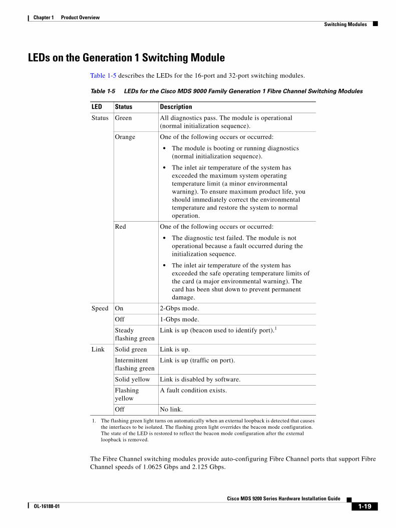
LEDs on the Generation 1 Switching ModuleTable 1-5 describes the LEDs for the 16-port and 32-port switching modules.
The Fibre Channel switching modules provide auto-configuring Fibre Channel ports that support Fibre Channel speeds of 1.0625 Gbps and 2.125 Gbps.
Table 1-5 LEDs for the Cisco MDS 9000 Family Generation 1 Fibre Channel Switching Modules
LED Status Description
Status Green All diagnostics pass. The module is operational (normal initialization sequence).
Orange One of the following occurs or occurred:
• The module is booting or running diagnostics (normal initialization sequence).
• The inlet air temperature of the system has exceeded the maximum system operating temperature limit (a minor environmental warning). To ensure maximum product life, you should immediately correct the environmental temperature and restore the system to normal operation.
Red One of the following occurs or occurred:
• The diagnostic test failed. The module is not operational because a fault occurred during the initialization sequence.
• The inlet air temperature of the system has exceeded the safe operating temperature limits of the card (a major environmental warning). The card has been shut down to prevent permanent damage.
Speed On 2-Gbps mode.
Off 1-Gbps mode.
Steady flashing green
Link is up (beacon used to identify port).1
1. The flashing green light turns on automatically when an external loopback is detected that causes the interfaces to be isolated. The flashing green light overrides the beacon mode configuration. The state of the LED is restored to reflect the beacon mode configuration after the external loopback is removed.
Link Solid green Link is up.
Intermittent flashing green
Link is up (traffic on port).
Solid yellow Link is disabled by software.
Flashing yellow
A fault condition exists.
Off No link.
1-19Cisco MDS 9200 Series Hardware Installation Guide
OL-16188-01
Chapter 1 Product Overview Services Modules
Services ModulesThe Cisco MDS 9200 Series supports the following hot-swappable services modules:
• 1 8/4-Port Multiservice Module
• 18/4-Port Multiservice Federal Information Processing Standards Module
• 14/2-Port Multiprotocol Services Module
• IP Storage Services Modules
• 32-Port Fibre Channel Storage Services Module
• 32-Port Fibre Channel Advanced Services Module
• Caching Services Module
The Cisco MDS 9200 Series supports one hot-swappable switching or services module in addition to the integrated module that is part of the supervisor module. Each module has temperature sensors and an EEPROM that stores serial number and model number information.
Note The internal bootflash installed on the modules are not field-replaceable units. Do not remove or replace internal bootflash on the modules. You cannot modify the factory installed bootflash.
18/4-Port Multiservice ModuleThe Cisco MDS 9000 Family 18/4-port Multiservice (MSM-18/4) module provides 18 autosensing 1-, 2-, and 4-Gbps Fibre Channel ports and four Gigabit Ethernet IP services ports. The MSM-18/4 module provides multiprotocol capabilities such as Fibre Channel, Fibre Channel over IP (FCIP), Small Computer System Interface over IP (iSCSI), IBM Fiber Connectivity (FICON), and FICON Control Unit Port (CUP) management.
The MSM-18/4 module provides 18 4-Gbps Fibre Channel interfaces for high-performance SAN and mainframe connectivity and four Gigabit Ethernet ports for FCIP and iSCSI storage services. Individual ports can be configured with hot-swappable short wavelength, long wavelength, extended-reach, coarse wavelength-division multiplexing (CWDM) or dense wavelength-division multiplexing (DWDM) Small Form-Factor Pluggables (SFPs) for connectivity up to 125 miles (200 km).
The MSM-18/4 module can minimize latency for disk and tape through FCIP write acceleration and FCIP tape write and read acceleration. The MSM-18/4 module provides up to 16 virtual Inter-Switch Link (ISL) connections on the four 1-Gigabit Ethernet ports through tunneling, and provides up to 4095 buffer-to-buffer credits that can be assigned to a single Fibre Channel port.
The MSM-18/4 supports hardware-based encryption and it is required to run the Storage Media Encryption (SME), which is a part of the Cisco SAN-OS. For more information on SME, see the Cisco MDS Storage Media Encryption Guide.
The MSM-18/4 supports SAN extension over IP and is compatible with current SAN extension products, such as, MPS-14/2, 9216i, and IPS. The MSM-18/4 provides an integrated next generation 4-Gbps FC platform for SAN extension. The MSM-18/4 module supports Internet Protocol version 6 (IPv6) as mandated by the U.S. Department of Defense (DoD), Japan, and China. The IPv6 support is provided for FCIP, iSCSI, and management traffic routed in-band and out-of-band.
The MSM-18/4 module provides intelligent diagnostics, protocol decoding, and network analysis tools wit h the integrated Call Home capability.
1-20Cisco MDS 9200 Series Hardware Installation Guide
OL-16188-01
Chapter 1 Product Overview Services Modules
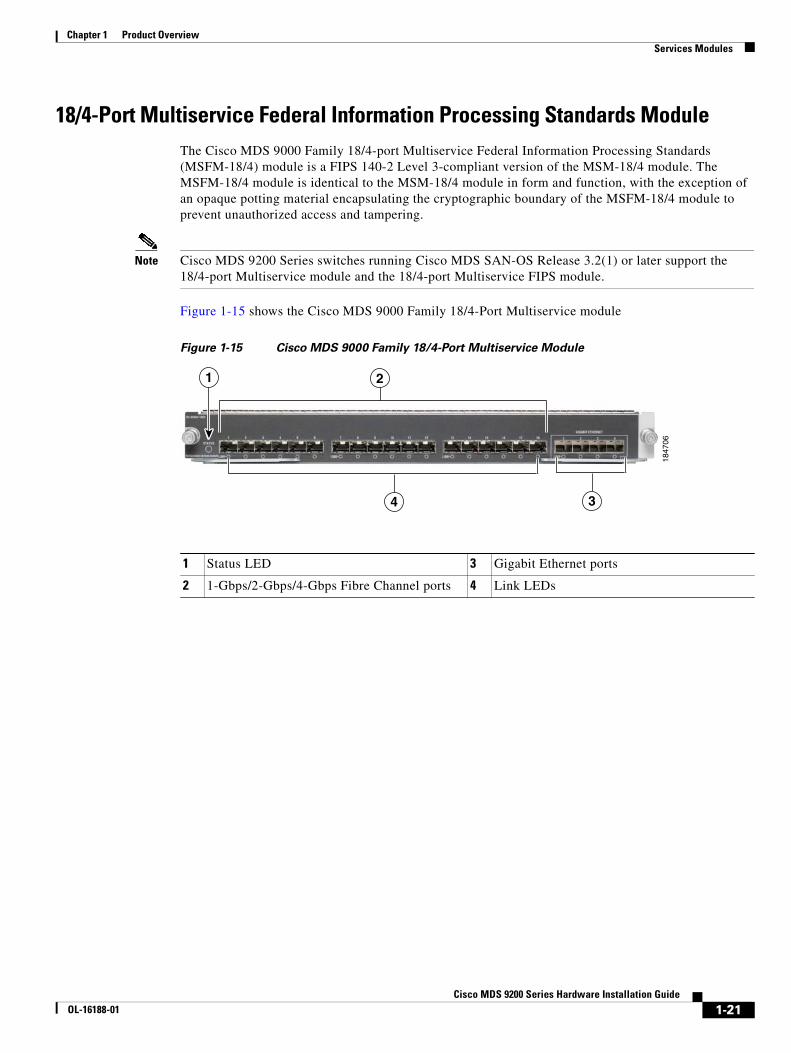
18/4-Port Multiservice Federal Information Processing Standards Module The Cisco MDS 9000 Family 18/4-port Multiservice Federal Information Processing Standards (MSFM-18/4) module is a FIPS 140-2 Level 3-compliant version of the MSM-18/4 module. The MSFM-18/4 module is identical to the MSM-18/4 module in form and function, with the exception of an opaque potting material encapsulating the cryptographic boundary of the MSFM-18/4 module to prevent unauthorized access and tampering.
Note Cisco MDS 9200 Series switches running Cisco MDS SAN-OS Release 3.2(1) or later support the 18/4-port Multiservice module and the 18/4-port Multiservice FIPS module.
Figure 1-15 shows the Cisco MDS 9000 Family 18/4-Port Multiservice module
Figure 1-15 Cisco MDS 9000 Family 18/4-Port Multiservice Module
1847
06
1 2
4 3
1 Status LED 3 Gigabit Ethernet ports
2 1-Gbps/2-Gbps/4-Gbps Fibre Channel ports 4 Link LEDs
1-21Cisco MDS 9200 Series Hardware Installation Guide
OL-16188-01
Chapter 1 Product Overview Services Modules
LEDs on the 18/4-Port Multiservice Module
Table 1-6 describes the LEDs for the Cisco MDS 9000 Family 18/4-port Multiservice module.
14/2-Port Multiprotocol Services ModuleThe 14/2-port Multiprotocol Services (MPS-14/2) module provides 14 1-Gbps/2-Gbps Fibre Channel autosensing ports and two 1-Gigabit Ethernet ports for iSCSI and FCIP over Gigabit Ethernet. The MPS-14/2 module supports the intelligent features available on other modules, including VSANs, security, and traffic management.
The 14 1-Gbps/2-Gbps autosensing Fibre Channel ports (labeled 1 through 14) are best used for applications requiring high bandwidth; for example, Inter-Switch Link (ISL) connections between switches and high-performance host or storage controllers. Each Fibre Channel port supports a sustained data rate of up to 2 Gbps in each direction.
The Cisco MDS 9216 Switch supports one MPS-14/2 module. The two Gigabit Ethernet ports (labeled 1 and 2) provide 1-Gbps throughput for IP services, including iSCSI and FCIP over Gigabit Ethernet. The MPS-14/2 also supports hardware-based encryption and compression for these Gigabit Ethernet ports. This hardware-based encryption handles the computationally intensive IPsec feature for IP services.
Table 1-6 LEDs for the Cisco MDS 9000 Family 18/4-Port Multiservice Modules
LED Status Description
Status Green All diagnostics pass. The module is operational (normal initialization sequence).
Orange One of the following occurs or occurred:
• The module is booting or running diagnostics (normal initialization sequence).
• The inlet air temperature of the system exceeded the maximum system operating temperature limit (a minor environmental warning). To ensure maximum product life, you should immediately correct the environmental temperature and restore the system to normal operation.
Red One of the following occurred:
• The diagnostic test failed. The module is not operational because a fault occurred during the initialization sequence.
• The inlet air temperature of the system exceeded the safe operating temperature limits of the card (a major environmental warning). The card shut down to prevent permanent damage.
Link Solid green
Link is up.
Solid yellow
Link is disabled by software.
Flashing yellow
A fault condition exists.
Off No link.
1-22Cisco MDS 9200 Series Hardware Installation Guide
OL-16188-01
Chapter 1 Product Overview Services Modules
The MPS-14/2 modules support FCIP compression to maximize the effective WAN bandwidth of SAN extension solutions. It achieves up to a 30-to-1 compression ratio, with typical ratios of 2-to-1 over a wide variety of data sources. With the addition of hardware-based compression, the MPS-14/2 module is able to provide optimal levels of compressed throughput for implementations across low to high-bandwidth links.
The Gigabit Ethernet ports on the MPS-14/2 module support iSCSI protocol, FCIP protocol, or both protocols simultaneously. For information about configuring the ports, see the Cisco MDS 9000 Family CLI Configuration Guide or the Cisco MDS 9000 Family Fabric Manager Configuration Guide.
The Fibre Channel port interfaces support hot-swappable Fibre Channel SFP transceivers, which can be short wavelength (SWL) for connectivity up to 1640 feet (500 meters), or long wavelength (LWL) for connectivity up to 6.2 miles (10 km). All interfaces are autosensing 1-Gbps or 2-Gbps compatible. The port interfaces also support coarse wavelength-division multiplexing (CWDM) SFP transceivers, which can be used for extended long wavelength (ELWL) transmission or for CWDM. See the “Supported Transceivers” section on page 1-35.
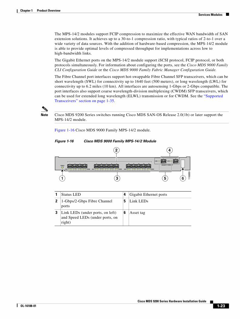
Note Cisco MDS 9200 Series switches running Cisco MDS SAN-OS Release 2.0(1b) or later support the MPS-14/2 module.
Figure 1-16 Cisco MDS 9000 Family MPS-14/2 module.
Figure 1-16 Cisco MDS 9000 Family MPS-14/2 Module
1 Status LED 4 Gigabit Ethernet ports
2 1-Gbps/2-Gbps Fibre Channel ports
5 Link LEDs
3 Link LEDs (under ports, on left) and Speed LEDs (under ports, on right)
6 Asset tag
—SPEED LINK—
LINK-
—SPEEDLINK—
STATUS
1 5 6 7 8 9
LINK— —SPEED
10 11 12 13 142 3 4
1 2
LINK-
GIGABIT E THERNET
1168
89
1 6
2 4
3 5
1-23Cisco MDS 9200 Series Hardware Installation Guide
OL-16188-01
Chapter 1 Product Overview Services Modules
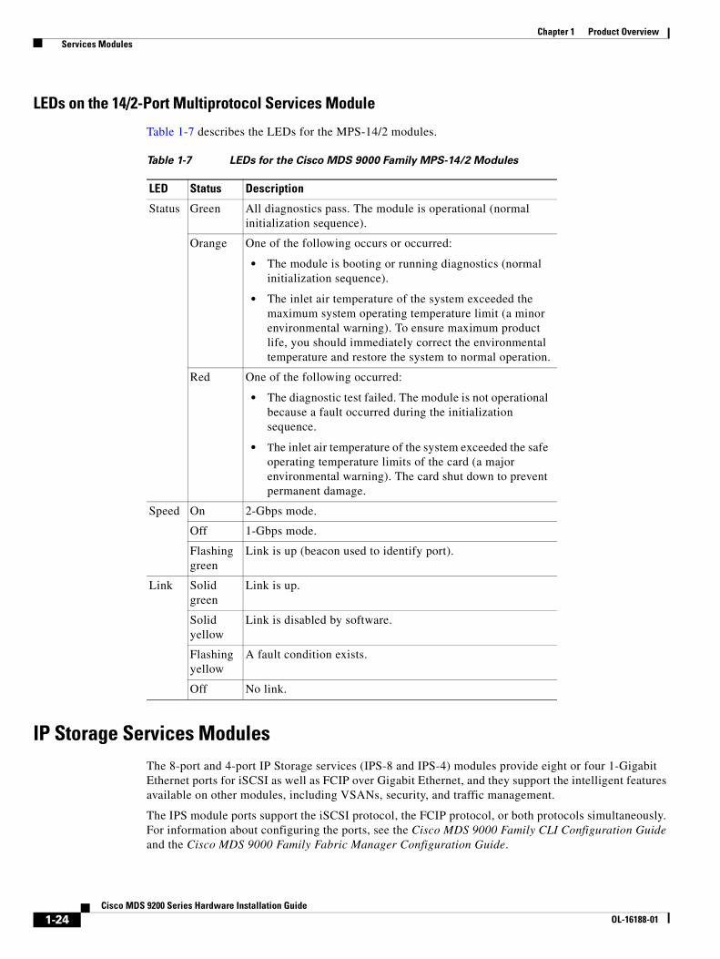
LEDs on the 14/2-Port Multiprotocol Services Module
Table 1-7 describes the LEDs for the MPS-14/2 modules.
IP Storage Services Modules The 8-port and 4-port IP Storage services (IPS-8 and IPS-4) modules provide eight or four 1-Gigabit Ethernet ports for iSCSI as well as FCIP over Gigabit Ethernet, and they support the intelligent features available on other modules, including VSANs, security, and traffic management.
The IPS module ports support the iSCSI protocol, the FCIP protocol, or both protocols simultaneously. For information about configuring the ports, see the Cisco MDS 9000 Family CLI Configuration Guide and the Cisco MDS 9000 Family Fabric Manager Configuration Guide.
Table 1-7 LEDs for the Cisco MDS 9000 Family MPS-14/2 Modules
LED Status Description
Status Green All diagnostics pass. The module is operational (normal initialization sequence).
Orange One of the following occurs or occurred:
• The module is booting or running diagnostics (normal initialization sequence).
• The inlet air temperature of the system exceeded the maximum system operating temperature limit (a minor environmental warning). To ensure maximum product life, you should immediately correct the environmental temperature and restore the system to normal operation.
Red One of the following occurred:
• The diagnostic test failed. The module is not operational because a fault occurred during the initialization sequence.
• The inlet air temperature of the system exceeded the safe operating temperature limits of the card (a major environmental warning). The card shut down to prevent permanent damage.
Speed On 2-Gbps mode.
Off 1-Gbps mode.
Flashing green
Link is up (beacon used to identify port).
Link Solid green
Link is up.
Solid yellow
Link is disabled by software.
Flashing yellow
A fault condition exists.
Off No link.
1-24Cisco MDS 9200 Series Hardware Installation Guide
OL-16188-01
Chapter 1 Product Overview Services Modules
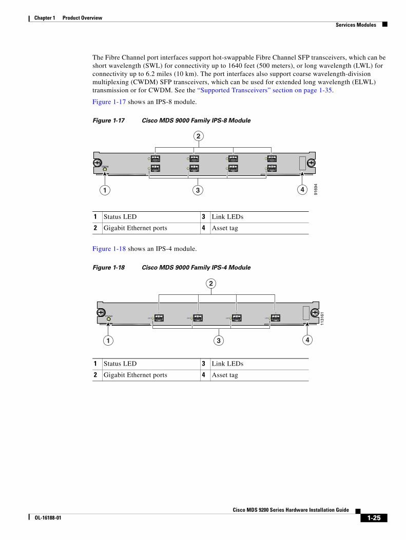
The Fibre Channel port interfaces support hot-swappable Fibre Channel SFP transceivers, which can be short wavelength (SWL) for connectivity up to 1640 feet (500 meters), or long wavelength (LWL) for connectivity up to 6.2 miles (10 km). The port interfaces also support coarse wavelength-division multiplexing (CWDM) SFP transceivers, which can be used for extended long wavelength (ELWL) transmission or for CWDM. See the “Supported Transceivers” section on page 1-35.
Figure 1-17 shows an IPS-8 module.
Figure 1-17 Cisco MDS 9000 Family IPS-8 Module
Figure 1-18 shows an IPS-4 module.
Figure 1-18 Cisco MDS 9000 Family IPS-4 Module
1 Status LED 3 Link LEDs
2 Gigabit Ethernet ports 4 Asset tag
9169
4
2
1 43
1 Status LED 3 Link LEDs
2 Gigabit Ethernet ports 4 Asset tag
1131
61LINK LINK LINK LINK
1 2 3 4
1 43
2
1-25Cisco MDS 9200 Series Hardware Installation Guide
OL-16188-01
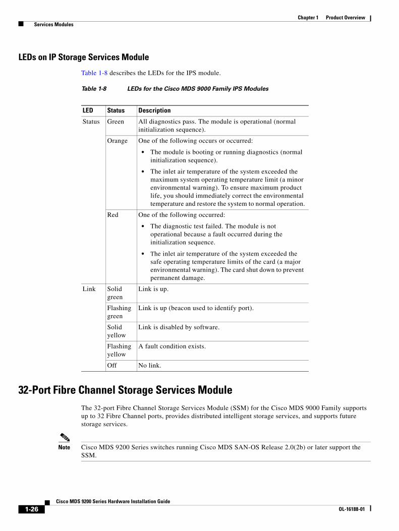
Chapter 1 Product Overview Services Modules
LEDs on IP Storage Services Module
Table 1-8 describes the LEDs for the IPS module.
32-Port Fibre Channel Storage Services ModuleThe 32-port Fibre Channel Storage Services Module (SSM) for the Cisco MDS 9000 Family supports up to 32 Fibre Channel ports, provides distributed intelligent storage services, and supports future storage services.
Note Cisco MDS 9200 Series switches running Cisco MDS SAN-OS Release 2.0(2b) or later support the SSM.
Table 1-8 LEDs for the Cisco MDS 9000 Family IPS Modules
LED Status Description
Status Green All diagnostics pass. The module is operational (normal initialization sequence).
Orange One of the following occurs or occurred:
• The module is booting or running diagnostics (normal initialization sequence).
• The inlet air temperature of the system exceeded the maximum system operating temperature limit (a minor environmental warning). To ensure maximum product life, you should immediately correct the environmental temperature and restore the system to normal operation.
Red One of the following occurred:
• The diagnostic test failed. The module is not operational because a fault occurred during the initialization sequence.
• The inlet air temperature of the system exceeded the safe operating temperature limits of the card (a major environmental warning). The card shut down to prevent permanent damage.
Link Solid green
Link is up.
Flashing green
Link is up (beacon used to identify port).
Solid yellow
Link is disabled by software.
Flashing yellow
A fault condition exists.
Off No link.
1-26Cisco MDS 9200 Series Hardware Installation Guide
OL-16188-01
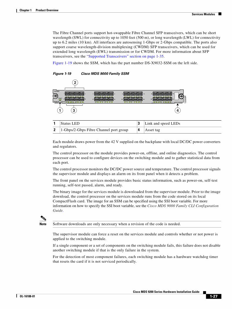
Chapter 1 Product Overview Services Modules
The Fibre Channel ports support hot-swappable Fibre Channel SFP transceivers, which can be short wavelength (SWL) for connectivity up to 1050 feet (500 m), or long wavelength (LWL) for connectivity up to 6.2 miles (10 km). All interfaces are autosensing 1-Gbps or 2-Gbps compatible. The ports also support coarse wavelength-division multiplexing (CWDM) SFP transceivers, which can be used for extended long wavelength (EWL) transmission or for CWDM. For more information about SFP transceivers, see the “Supported Transceivers” section on page 1-35.
Figure 1-19 shows the SSM, which has the part number DS-X9032-SSM on the left side.
Figure 1-19 Cisco MDS 9000 Family SSM
Each module draws power from the 42 V supplied on the backplane with local DC/DC power converters and regulators.
The control processor on the module provides power-on, offline, and online diagnostics. The control processor can be used to configure devices on the switching module and to gather statistical data from each port.
The control processor monitors the DC/DC power source and temperature. The control processor signals the supervisor module and displays an alarm on its front panel when it detects a problem.
The front panel on the services module provides basic status information, such as power-on, self-test running, self-test passed, alarm, and ready.
The binary image for the services module is downloaded from the supervisor module. Prior to the image download, the control processor on the services module runs from the code stored on its local CompactFlash card. The image for an SSM can be specified using the SSI boot variable. For more information on how to specify the SSI boot variable, see the Cisco MDS 9000 Family CLI Configuration Guide.
Note Software downloads are only necessary when a revision of the code is needed.
The supervisor module can force a reset on the services module and controls whether or not power is applied to the switching module.
If a single component or a set of components on the switching module fails, this failure does not disable another switching module if that is the only failure in the system.
For the detection of most component failures, each switching module has a hardware watchdog timer that resets the card if it is not serviced periodically.
1 Status LED 3 Link and speed LEDs
2 1-Gbps/2-Gbps Fibre Channel port group 4 Asset tag
1200
94
2
43
17 20
4 5
21 24
8 9
25 28
12 13
29 32
16
Storage Services Module
1
DS-X9032
1-27Cisco MDS 9200 Series Hardware Installation Guide
OL-16188-01

Chapter 1 Product Overview Services Modules
LEDs on the Storage Services Module
Table 1-9 describes the LEDs for the Cisco MDS 9000 Family Storage Services Module.
32-Port Fibre Channel Advanced Services ModuleThe Cisco MDS 9000 Family 32-port Fibre Channel Advanced Services Module (ASM) enables pooling of heterogeneous storage for increased storage utilization, simplified storage management, and reduced total cost of storage ownership. The ASM incorporates all the capabilities of the Cisco MDS 9000 DS-X9032 Fibre Channel switching module and also provides scalable, in-band storage virtualization services. The ASM module makes it possible to allocate bandwidth optimally.
Table 1-9 LEDs for the Cisco MDS 9000 Family Storage Services Module
LED Status Description
Status Green All diagnostics pass. The module is operational (normal initialization sequence).
Orange One of the following occurs or occurred:
• The module is booting or running diagnostics (normal initialization sequence).
• The inlet air temperature of the system exceeded the maximum system operating temperature limit (a minor environmental warning). To assure maximum product life, you should immediately correct the environmental temperature and restore the system to normal operation.
Red One of the following occurs or occurred:
• The diagnostic test failed. The module is not operational because a fault occurred during the initialization sequence.
• The inlet air temperature of the system exceeded the safe operating temperature limits of the card (a major environmental warning). The card shut down to prevent permanent damage.
Speed On 2-Gbps mode.
Off 1-Gbps mode.
Link Solid green Link is healthy.
Steady flashing green
Link is healthy and beacon is enabled.
Intermittent flashing green
Link is up and traffic is flowing through port.
Solid yellow Link is disabled by software.
Flashing yellow A fault condition exists.
Off No link.
1-28Cisco MDS 9200 Series Hardware Installation Guide
OL-16188-01

Chapter 1 Product Overview Services Modules
The Fibre Channel port interfaces support hot-swappable Fibre Channel SFP transceivers, which can be SWL for connectivity up to 1640 feet (500 meters), or LWL for connectivity up to 6.2 miles (10 km). All interfaces are autosensing 1-Gbps or 2-Gbps compatible. The port interfaces also support CWDM SFP transceivers, which can be used for extended long wavelength (ELWL) transmission or for CWDM. See the “Supported Transceivers” section on page 1-35.
Figure 1-20 shows the Cisco MDS 9000 Family Fibre Channel ASM.
Figure 1-20 Cisco MDS 9000 Family ASM
Each module draws power from the 42 V supplied on the backplane with local DC/DC power converters and regulators.
The control processor on the module provides power-on, offline, and online diagnostics. The control processor can be used to configure devices on the switching module and to gather statistical data from each port.
The control processor monitors the DC/DC power source and temperature. The control processor signals the supervisor module and displays an alarm on its front panel when a problem is detected.
The front panel on the services module provides basic status information, such as power-on, self-test running, self-test passed, alarm, and ready.
The binary image for the services module is downloaded from the supervisor module. Prior to the image download, the control processor on the switching module runs from code stored on its local CompactFlash card. The image for an ASM-SFN can be specified using the ASM-SFN boot variable. For more information on how to specify the SSI boot variable, see the Cisco MDS 9000 Family CLI Configuration Guide.
Note Software downloads are only necessary when a revision of the code is needed.
The supervisor module can force a reset on the services module and controls whether power is applied to the switching module.
If a single component or a set of components on the switching module fails, this failure does not disable another switching module if that is the only failure in the system.
Each ASM has a hardware watchdog timer to detect most component failures. The watchdog timer resets the card if it is not serviced periodically.
9429
8
2
1 43
17 20
4 5
21 24
8 9
25 28
12 13
29 32
16
DS-X9032
1 Status LED 3 Link and Speed LEDs
2 1-Gbps/2-Gbps Fibre Channel port group 4 Asset tag
1-29Cisco MDS 9200 Series Hardware Installation Guide
OL-16188-01
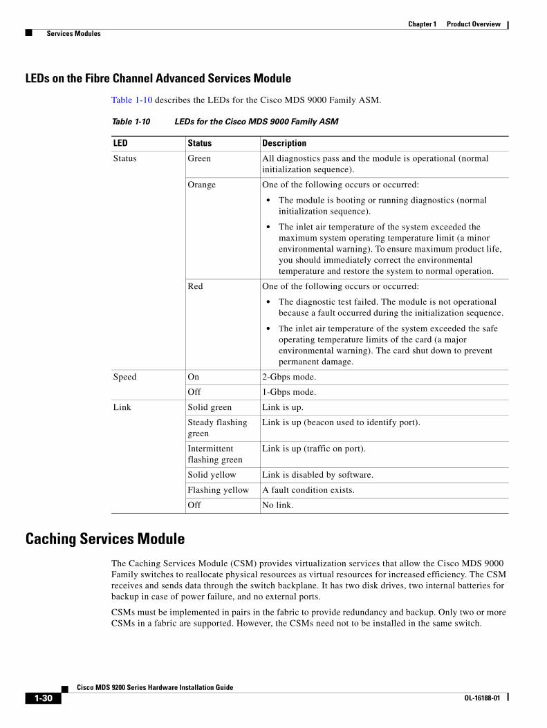
Chapter 1 Product Overview Services Modules
LEDs on the Fibre Channel Advanced Services Module
Table 1-10 describes the LEDs for the Cisco MDS 9000 Family ASM.
Caching Services ModuleThe Caching Services Module (CSM) provides virtualization services that allow the Cisco MDS 9000 Family switches to reallocate physical resources as virtual resources for increased efficiency. The CSM receives and sends data through the switch backplane. It has two disk drives, two internal batteries for backup in case of power failure, and no external ports.
CSMs must be implemented in pairs in the fabric to provide redundancy and backup. Only two or more CSMs in a fabric are supported. However, the CSMs need not to be installed in the same switch.
Table 1-10 LEDs for the Cisco MDS 9000 Family ASM
LED Status Description
Status Green All diagnostics pass and the module is operational (normal initialization sequence).
Orange One of the following occurs or occurred:
• The module is booting or running diagnostics (normal initialization sequence).
• The inlet air temperature of the system exceeded the maximum system operating temperature limit (a minor environmental warning). To ensure maximum product life, you should immediately correct the environmental temperature and restore the system to normal operation.
Red One of the following occurs or occurred:
• The diagnostic test failed. The module is not operational because a fault occurred during the initialization sequence.
• The inlet air temperature of the system exceeded the safe operating temperature limits of the card (a major environmental warning). The card shut down to prevent permanent damage.
Speed On 2-Gbps mode.
Off 1-Gbps mode.
Link Solid green Link is up.
Steady flashing green
Link is up (beacon used to identify port).
Intermittent flashing green
Link is up (traffic on port).
Solid yellow Link is disabled by software.
Flashing yellow A fault condition exists.
Off No link.
1-30Cisco MDS 9200 Series Hardware Installation Guide
OL-16188-01

Chapter 1 Product Overview Services Modules
The CSM shuts down if the software failure or an external power failure occurs, or if the module is separated from the backplane while it is still powered on. The CSM automatically backs up the data in memory to the disk drives and then shuts down. The CSM batteries provide adequate power to back up data without external power.
Figure 1-21 shows the Cisco MDS 9000 Family CSM.
Figure 1-21 Cisco MDS 9000 Family CSM
Figure 1-22 shows the location of the disk drives and batteries on the CSM.
Caution The batteries are shipped fully charged and should be handled accordingly.
1 Status LED 5 Disk 1 Status LED
2 Battery LED 6 Node 2 LEDs
3 Node 1 LEDs 7 Node 2 Status LED
4 Node 1 Status LED 8 Disk 2 Status LED
9162
6STATUS
DS-X9560-SMXX
BATTERY STATUS
NODE 1 NODE 2
DISK STATUS DISK
Cashing Services Module
3 6
8521 4 7
1-31Cisco MDS 9200 Series Hardware Installation Guide
OL-16188-01
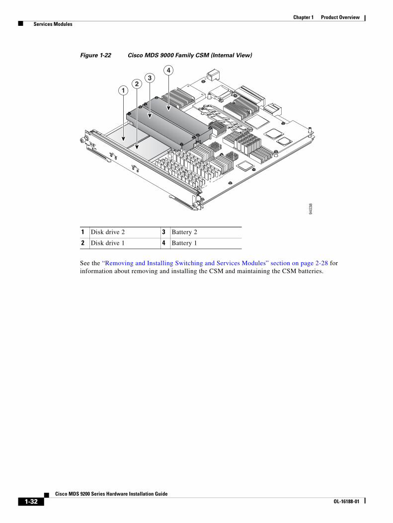
Chapter 1 Product Overview Services Modules
Figure 1-22 Cisco MDS 9000 Family CSM (Internal View)
See the “Removing and Installing Switching and Services Modules” section on page 2-28 for information about removing and installing the CSM and maintaining the CSM batteries.
1 Disk drive 2 3 Battery 2
2 Disk drive 1 4 Battery 1
9403
8
1
34
2
1-32Cisco MDS 9200 Series Hardware Installation Guide
OL-16188-01
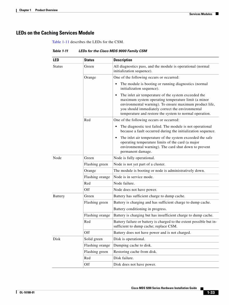
Chapter 1 Product Overview Services Modules
LEDs on the Caching Services Module
Table 1-11 describes the LEDs for the CSM.
Table 1-11 LEDs for the Cisco MDS 9000 Family CSM
LED Status Description
Status Green All diagnostics pass, and the module is operational (normal initialization sequence).
Orange One of the following occurs or occurred:
• The module is booting or running diagnostics (normal initialization sequence).
• The inlet air temperature of the system exceeded the maximum system operating temperature limit (a minor environmental warning). To ensure maximum product life, you should immediately correct the environmental temperature and restore the system to normal operation.
Red One of the following occurs or occurred:
• The diagnostic test failed. The module is not operational because a fault occurred during the initialization sequence.
• The inlet air temperature of the system exceeded the safe operating temperature limits of the card (a major environmental warning). The card shut down to prevent permanent damage.
Node Green Node is fully operational.
Flashing green Node is not yet part of a cluster.
Orange The module is booting or node is administratively down.
Flashing orange Node is in service mode.
Red Node failure.
Off Node does not have power.
Battery Green Battery has sufficient charge to dump cache.
Flashing green Battery is charging and has sufficient charge to dump cache.
Battery conditioning in progress.
Flashing orange Battery is charging but has insufficient charge to dump cache.
Red Battery failure or battery is charged to the extent possible but in-sufficient to dump cache; replace CSM.
Off Battery does not have power and is not charged.
Disk Solid green Disk is operational.
Flashing orange Dumping cache to disk.
Flashing green Restoring cache from disk.
Red Disk failure.
Off Disk does not have power.
1-33Cisco MDS 9200 Series Hardware Installation Guide
OL-16188-01

Chapter 1 Product Overview Power Supplies
Power SuppliesThe Cisco MDS 9200 Series supports dual hot-swappable 845-W AC power supplies, each of which can supply sufficient power to the entire chassis should one power supply fail. The power supplies monitor their output voltage and provide status to the supervisor module. To prevent the unexpected shutdown of an optional module, power management software only allows a module to power up if adequate power is available.
The Cisco MDS 9200 Series power supplies can be configured to be redundant or combined. By default, they are configured as redundant, so that if one fails, the remaining power supply can still power the entire system. For information on how to configure the power supplies, see the Cisco MDS 9000 Family CLI Configuration Guide or the Cisco MDS 9000 Family Fabric Manager Configuration Guide.
The power supplies, which are accessed from the rear of the chassis, are illustrated in Figure 1-23.
Figure 1-23 Cisco MDS 9200 Series with 845-W Dual Power Supplies
Table 1-12 describes the LEDs for the Cisco MDS 9200 Series power supplies.
1 Power supply switch 3 Power supply handle
2 AC power connection 4 Power supply LEDs
PWR-845-AC
100-240V 12-5A50/60 Hz
INPUT OK
FAN OK
OUTPUT FAIL
ALL FASTENERS MUST BE FULLY ENGAGEDPRIOR TO OPERATING OF POWER SUPPLY
PWR-845-AC
100-240V 12-5A50/60 Hz
INPUT OK
FAN OK
OUTPUT FAIL
ALL FASTENERS MUST BE FULLY ENGAGEDPRIOR TO OPERATING OF POWER SUPPLY
4
3
9400
2
1
2
Table 1-12 LEDs for the Cisco MDS 9200 Series Power Supplies
LED Status Description
Input OK Green AC input is good and power supply is functioning normally.
Off Power supply is turned off or is not seated properly in the chassis.
Fan OK Green Power supply fans are operating properly.
Off Fan is not operating or power supply is off.
Output Fail Red Power supply is not in a stable state. If this indication continues after initial power on, check that all connections are secure, including the system fan tray.
Off Normal operation or power supply is turned off.
1-34Cisco MDS 9200 Series Hardware Installation Guide
OL-16188-01
Chapter 1 Product Overview Fan Module
Fan ModuleThe Cisco MDS 9200 Series supports a hot-swappable fan module with four fans. The fan module provides 80 cfm (cubic feet per minute) of cooling per slot, allowing 400 W of power dissipation per slot. Sensors on the supervisor module monitor the internal air temperature. If the air temperature exceeds a preset lower-level threshold, the environmental monitor displays warning messages. If the air temperature exceeds a preset higher-level threshold, the switch will shut down.
If one or more fans within the fan module fail, the Fan Status LED turns red and the module must be replaced. Individual fans cannot be replaced, you must replace the entire fan module. If the higher-level temperature threshold is not exceeded, the switch continues to run for five minutes after the fan module is removed. This means you can swap out a fan module without having to bring the system down. To replace a fan module, see the “Removing and Installing the Fan Module” section on page 2-38. The fan module has one Status LED that indicates the following conditions:
• Green—Fan module is operating normally.
• Red—One or more fans failed. Fan module should be replaced.
• Off—Fan module is not properly seated in the chassis or power supply has failed.
Caution The Cisco MDS 9000 Family switches have internal temperature sensors that are capable of shutting down the system if the temperature at different points within the chassis exceed certain safety thresholds. To be effective, the temperature sensors require the presence of airflow; therefore, in the event a fan module is removed from the chassis, the Cisco MDS 9000 Family switches shut down after five minutes to prevent potentially undetectable overheating. However, the switches shut down sooner if the higher-level temperature threshold is exceeded.
Supported TransceiversThe following types of transceivers are available from Cisco and are supported on the Cisco MDS 9200 Series:
• X2 Fibre Channel transceivers
• Fibre Channel SFP transceivers, in either SWL or LWL
• Combination Fibre Channel/Gigabit Ethernet SFP transceivers, in either SWL or LWL
• Combination Fibre Channel/Gigabit Ethernet CWDM SFP transceivers, which can be used for ELWL transmission or for CWDM
• Gigabit Ethernet SFP transceiver, 1-Gbps copper
• Fibre Channel DWDM SFP transceiver, which can be used for ELWL transmission or for DWDM
Note Switches running Cisco MDS SAN-OS Release 1.1(1a) or later support combination Fibre Channel/Gigabit Ethernet SFP transceivers.
The transceivers are field-replaceable and hot-swappable. You can use any combination of SFP transceivers that are supported by the switch. The only restrictions are that SWL transceivers must be paired with SWL transceivers, and LWL transceivers with LWL transceivers, and the cable must not exceed the stipulated cable length for reliable communications.
1-35Cisco MDS 9200 Series Hardware Installation Guide
OL-16188-01

Chapter 1 Product Overview Supported Transceivers
For more information about the X2 transceiver, see the “X2 Transceiver Specifications” section on page B-6.
For more information about a specific Cisco SFP transceiver, see the “SFP Transceiver Specifications” section on page B-9. SFP transceivers can be ordered separately or with the Cisco MDS 9200 Series.
Note Use only Cisco transceivers in the Cisco MDS 9200 Series. Each Cisco transceiver is encoded with model information that enables the switch to verify that the transceiver meets the requirements for the switch.
X2 Fibre Channel TransceiversThe X2 Fibre Channel transceiver is a small form-factor optimized for 10-Gbps applications and uses an SC connector. The X2 transceiver is ideally suited for Ethernet, Fibre Channel and telecom switches, and standard peripheral component interconnect (PCI)-based server and storage connections. The X2 provides robust thermal performance and electromagnetic shielding.
For more information on X2 transceiver specifications, see the “X2 Transceiver Specifications” section on page B-6.
Fibre Channel SFP TransceiversCisco Fibre Channel SFP transceivers are available in SWL or LWL versions. Both of these versions are 1-Gbps/2-Gbps/4-Gbps capable.
Cisco Fibre Channel SFP transceivers have LC connectors and comply with 1-Gbps/2-Gbps/4-Gbps Fibre Channel standards.
For more information about the Fibre Channel SFP transceiver specifications, see the “SFP Transceiver Specifications” section on page B-9.
Combination Fibre Channel/Gigabit Ethernet SFP TransceiversThe combination Fibre Channel/Gigabit Ethernet SFP transceivers from Cisco Systems are available in SWL or LWL versions. Both of these versions are 1-Gbps/2-Gbps capable.
The combination SFP transceivers from Cisco Systems have LC connectors and comply with 1-Gbps/2-Gbps Fibre Channel as defined in FC-PI 10.0 2 and Gigabit Ethernet as defined in IEEE 802.3z.
For more information on the Fibre Channel/Gigabit Ethernet SFP transceiver specifications, see the “SFP Transceiver Specifications” section on page B-9.
1-36Cisco MDS 9200 Series Hardware Installation Guide
OL-16188-01
Chapter 1 Product Overview Supported Transceivers
CWDM Combination Fibre Channel/Gigabit Ethernet SFP TransceiversAll Fibre Channel and Gigabit Ethernet ports in the Cisco MDS 9200 Series support 1-Gbps/2-Gbps CWDM SFP transceivers. In addition, the Fibre Channel ports on Cisco MDS 9222i also support 4-Gbps CWDM SFP transceivers.
The Cisco CWDM SFP transceivers have LC connectors and support both Gigabit Ethernet and Fibre Channel (1-Gbps/2-Gbps). They match the wavelength plan of Cisco CWDM GBICs and Cisco CWDM optical add/drop multiplexers (OADMs).
CWDM SFP transceivers can be used in two ways:
• CWDM transmission can send and receive up to eight laser wavelengths carrying different signals simultaneously on the same optical fiber using an OADM.
• ELWL signals can transmit over longer distances than LWL SFP transceivers.
There are eight different “colors” of CWDM SFP transceivers, one for each fixed wavelength. The fiber optic cables from the CWDM SFP transceivers must be connected to an OADM. The OADM combines the wavelengths of the different outgoing signals into one composite send signal. The OADM also separates the received transmissions into the different wavelengths and sends them to the corresponding CWDM SFP transceiver.
For more information on the CWDM SFP transceiver specifications, see the “SFP Transceiver Specifications” section on page B-9.
Gigabit Ethernet SFP TransceiversThe 4-port and 8-port IP Storage services (IPS-4 and IPS-8) modules provide four or eight 1-Gigabit Ethernet ports that support Gigabit Ethernet SFP transceivers. The Gigabit Ethernet SFP transceivers have RJ-45 connectors and support Gigabit Ethernet (1-Gbps).
For more information on the Gigabit Ethernet SFP transceiver specifications, see the “SFP Transceiver Specifications” section on page B-9.
DWDM Fibre Channel SFP TransceiversFibre Channel ports on Cisco MDS 9222i support 2-Gbps DWDM SFP transceivers. The Cisco DWDM Fibre Channel SFP transceivers have LC connectors and support Fibre Channel (1-Gbps/2-Gbps). The DWDM SFP transceivers match the International Telecommunications Union (ITU) 100-Ghz wavelength grid and the wavelength plan of Cisco 100-Ghz ONS product family.
The DWDM SFP transceivers have the following capabilities:
• DWDM transmission can send and receive up to 32 laser wavelengths carrying different signals simultaneously on the same optical fiber by using an optical filter.
• ELWL signals can transmit over longer distances than LWL SFP transceivers.
For more information on the DWDM SFP transceiver specifications, see the “SFP Transceiver Specifications” section on page B-9.
1-37Cisco MDS 9200 Series Hardware Installation Guide
OL-16188-01

Chapter 1 Product Overview Supported Transceivers
1-38Cisco MDS 9200 Series Hardware Installation Guide
OL-16188-01
Send documenta t ion comments to mds feedba ck -doc@c i sco .com
COL-16188-01
C H A P T E R 2
Installing the Cisco MDS 9200 SeriesThis chapter describes how to install the Cisco MDS 9200 Series and its components, and it includes the following information:
• Preinstallation, page 2-2
• Installing the Chassis in a Cabinet or Rack, page 2-5
• Installing the Switch in a Cabinet with Insufficient Front Clearance, page 2-11
• System Grounding, page 2-19
• Grounding the Chassis, page 2-24
• Starting Up the Switch, page 2-26
• Removing and Installing Components, page 2-28
Note Before you install, operate, or service the system, read the Regulatory Compliance and Safety Information for the Cisco MDS 9000 Family for important safety information.
Warning IMPORTANT SAFETY INSTRUCTIONS
This warning symbol means danger. You are in a situation that could cause bodily injury. Before you work on any equipment, be aware of the hazards involved with electrical circuitry and be familiar with standard practices for preventing accidents. Use the statement number provided at the end of each warning to locate its translation in the translated safety warnings that accompanied this device. Statement 1071
SAVE THESE INSTRUCTIONS
Warning This unit is intended for installation in restricted access areas. A restricted access area can be accessed only through the use of a special tool, lock and key, or other means of security. Statement 1017
Warning Only trained and qualified personnel must be allowed to install, replace, or service this equipment. Statement 1030
2-1isco MDS 9200 Series Hardware Installation Guide
Chapter 2 Installing the Cisco MDS 9200 Series Preinstallation
Warning A readily accessible two-poled disconnect device must be incorporated in the fixed wiring. Statement 1022
Note Each new switch requires a license. For information on licensing, see the Cisco MDS 9000 Family CLI Configuration Guide or the Cisco MDS 9000 Family Fabric Manager Configuration Guide.
PreinstallationThis section includes the following topics:
• Installation Options, page 2-2
• Installation Guidelines, page 2-3
• Required Equipment, page 2-4
• Unpacking and Inspecting the Switch, page 2-4
Installation OptionsThe Cisco MDS 9200 Series can be installed using the following methods:
• In an open EIA rack, using:
– The rack-mount kit shipped with the switch
– The telco and EIA Shelf Bracket Kit (an optional kit, purchased separately) in addition to the rack-mount kit shipped with the switch
• In a perforated or solid-walled EIA cabinet, using:
– The rack-mount kit shipped with the switch
– The telco and EIA Shelf Bracket Kit (an optional kit, purchased separately) in addition to the rack-mount kit shipped with the switch
• In a two-post telco rack, using:
– The telco and EIA Shelf Bracket Kit (an optional kit, purchased separately) in addition to the front brackets shipped with the switch
For instructions on installing the switch using the rack-mount kit shipped with the switch, see the “Installing the Chassis in a Cabinet or Rack” section on page 2-5.
For instructions on installing the switch using the optional, separately purchased telco and EIA Shelf Bracket Kit, see the “Cisco MDS 9000 Family telco and EIA Shelf Bracket” section on page A-4.
Note The optional telco and EIA Shelf Bracket Kit is not provided with the switch. To order the kit, contact your switch provider.
2-2Cisco MDS 9200 Series Hardware Installation Guide
OL-16188-01
Chapter 2 Installing the Cisco MDS 9200 Series Preinstallation
Installation GuidelinesFollow these guidelines when installing the Cisco MDS 9200 Series:
• Plan your site configuration and prepare the site before installing the chassis. Appendix D, “Site Planning and Maintenance Records,” lists the recommended site planning tasks.
• Record the information listed in Appendix D, “Site Planning and Maintenance Records,” as you install and configure the switch.
• Ensure that there is adequate space around the switch to allow for servicing the switch and for adequate airflow (Appendix B, “Technical Specifications,” lists airflow requirements).
• Ensure that the air-conditioning meets the heat dissipation requirements listed in Appendix B, “Technical Specifications.”
• Ensure that the cabinet or rack meets the requirements listed in Appendix A, “Cabinet and Rack Installation.”
Note Jumper power cords are available for use in a cabinet. See the “Jumper Power Cord” section on page C-11.
• Ensure that the chassis is adequately grounded. If the switch is not mounted in a grounded rack, Cisco recommends connecting both the system ground on the chassis and the power supply ground to an earth ground.
• Ensure that the site power meets the power requirements listed in Appendix B, “Technical Specifications.” If available, you can use an uninterruptible power supply (UPS) to protect against power failures.
Caution Avoid UPS types that use ferroresonant technology. These UPS types can become unstable with systems like the Cisco MDS 9000 Family, which can have substantial current draw fluctuations because of fluctuating data traffic patterns.
• Ensure that circuits are sized according to local and national codes. For North America, the 845-W power supply requires a 15-A or 20-A circuit.
If you are using a 200- or 240-VAC power source in North America, the circuit must be protected by a two-pole circuit breaker.
Caution To prevent loss of input power, ensure the total maximum loads on the circuits supplying power to the switch are within the current ratings for the wiring and breakers.
• Use the following screw torques when installing the switch:
– Captive screws: 4 in-lb
– M3 screws: 4 in-lb
– M4 screws: 12 in-lb
– 10-32 screws: 20 in-lb
– 12-24 screws: 30 in-lb
2-3Cisco MDS 9200 Series Hardware Installation Guide
OL-16188-01
Chapter 2 Installing the Cisco MDS 9200 Series Preinstallation
Required EquipmentBefore beginning the installation, ensure that the following items are ready:
• Number 1 and number 2 Phillips screwdrivers with torque capability
• 3/16-in. flat-blade screwdriver
• Tape measure and level
• ESD wrist strap or other grounding device
• Antistatic mat or antistatic foam
The following additional items (not found in the accessory kit) are required to ground the chassis:
• Grounding cable (6 AWG recommended), sized according to local and national installation requirements; the required length depends on the proximity of the Cisco MDS 9200 Series to proper grounding facilities
• Crimping tool large enough to accommodate girth of lug
• Wire-stripping tool
Unpacking and Inspecting the Switch
Caution When handling switch components, wear an ESD strap and handle modules by the carrier edges only. An ESD socket is provided on the chassis. For the ESD socket to be effective, the chassis must be grounded through the power cable, the chassis ground, or the metal-to-metal contact with a grounded rack.
Tip Keep the shipping container in case the chassis requires shipping in the future.
Note If you purchased Cisco support through a Cisco reseller, contact the reseller directly. If you purchased support directly from Cisco Systems, contact Cisco Technical Support at this URL: http://www.cisco.com/warp/public/687/Directory/DirTAC.shtml
Note The switch is thoroughly inspected before shipment. If any damage occurred during transportation or any items are missing, contact your customer representative immediately.
To inspect the shipment, follow these steps:
Step 1 Compare the shipment to the equipment list provided by your customer service representative and verify that you have received all items, including the following:
• Print documentation and CD-ROMs
• Grounding lug kit
• Rack-mount kit
• ESD wrist strap
2-4Cisco MDS 9200 Series Hardware Installation Guide
OL-16188-01
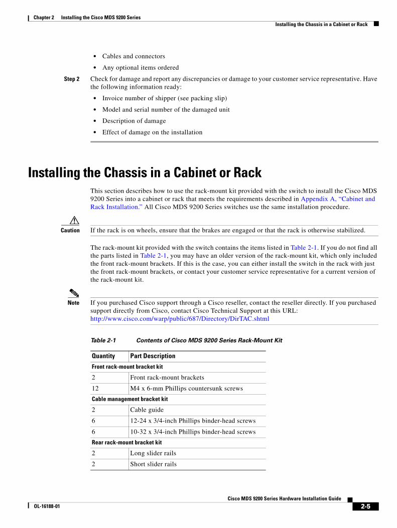
Chapter 2 Installing the Cisco MDS 9200 Series Installing the Chassis in a Cabinet or Rack
• Cables and connectors
• Any optional items ordered
Step 2 Check for damage and report any discrepancies or damage to your customer service representative. Have the following information ready:
• Invoice number of shipper (see packing slip)
• Model and serial number of the damaged unit
• Description of damage
• Effect of damage on the installation
Installing the Chassis in a Cabinet or RackThis section describes how to use the rack-mount kit provided with the switch to install the Cisco MDS 9200 Series into a cabinet or rack that meets the requirements described in Appendix A, “Cabinet and Rack Installation.” All Cisco MDS 9200 Series switches use the same installation procedure.
Caution If the rack is on wheels, ensure that the brakes are engaged or that the rack is otherwise stabilized.
The rack-mount kit provided with the switch contains the items listed in Table 2-1. If you do not find all the parts listed in Table 2-1, you may have an older version of the rack-mount kit, which only included the front rack-mount brackets. If this is the case, you can either install the switch in the rack with just the front rack-mount brackets, or contact your customer service representative for a current version of the rack-mount kit.
Note If you purchased Cisco support through a Cisco reseller, contact the reseller directly. If you purchased support directly from Cisco, contact Cisco Technical Support at this URL: http://www.cisco.com/warp/public/687/Directory/DirTAC.shtml
Table 2-1 Contents of Cisco MDS 9200 Series Rack-Mount Kit
Quantity Part Description
Front rack-mount bracket kit
2 Front rack-mount brackets
12 M4 x 6-mm Phillips countersunk screws
Cable management bracket kit
2 Cable guide
6 12-24 x 3/4-inch Phillips binder-head screws
6 10-32 x 3/4-inch Phillips binder-head screws
Rear rack-mount bracket kit
2 Long slider rails
2 Short slider rails
2-5Cisco MDS 9200 Series Hardware Installation Guide
OL-16188-01
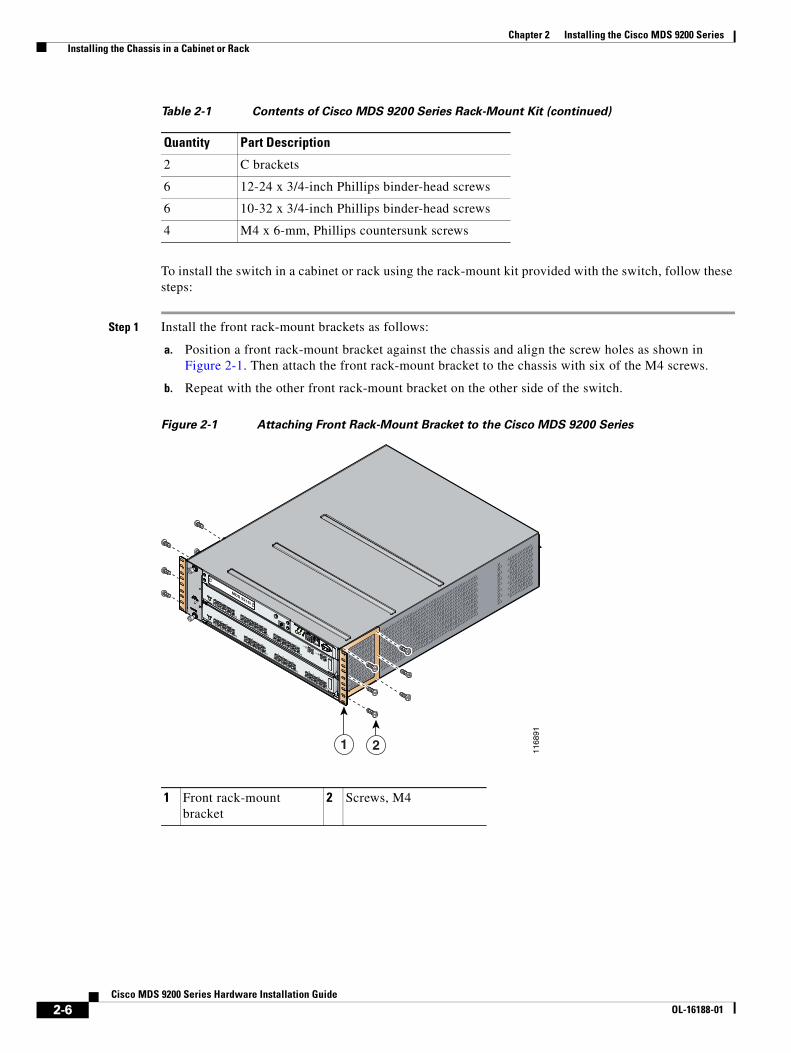
Chapter 2 Installing the Cisco MDS 9200 Series Installing the Chassis in a Cabinet or Rack
To install the switch in a cabinet or rack using the rack-mount kit provided with the switch, follow these steps:
Step 1 Install the front rack-mount brackets as follows:
a. Position a front rack-mount bracket against the chassis and align the screw holes as shown in Figure 2-1. Then attach the front rack-mount bracket to the chassis with six of the M4 screws.
b. Repeat with the other front rack-mount bracket on the other side of the switch.
Figure 2-1 Attaching Front Rack-Mount Bracket to the Cisco MDS 9200 Series
2 C brackets
6 12-24 x 3/4-inch Phillips binder-head screws
6 10-32 x 3/4-inch Phillips binder-head screws
4 M4 x 6-mm, Phillips countersunk screws
Table 2-1 Contents of Cisco MDS 9200 Series Rack-Mount Kit (continued)
Quantity Part Description
1 Front rack-mount bracket
2 Screws, M4
1168
91
MDS 9216i
GE1
LINK
GE2
LINK
5
6
7
8
9
10
11
12
13
14
1
2
3
4
1 2
2-6Cisco MDS 9200 Series Hardware Installation Guide
OL-16188-01
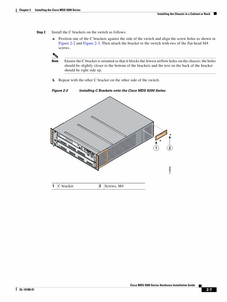
Chapter 2 Installing the Cisco MDS 9200 Series Installing the Chassis in a Cabinet or Rack
Step 2 Install the C brackets on the switch as follows:
a. Position one of the C brackets against the side of the switch and align the screw holes as shown in Figure 2-2 and Figure 2-3. Then attach the bracket to the switch with two of the flat-head M4 screws.
Note Ensure the C bracket is oriented so that it blocks the fewest airflow holes on the chassis; the holes should be slightly closer to the bottom of the brackets and the text on the back of the bracket should be right side up.
b. Repeat with the other C bracket on the other side of the switch.
Figure 2-2 Installing C Brackets onto the Cisco MDS 9200 Series
1 C bracket 2 Screws, M4
MDS 9216i
GE1
LINK
GE2
LINK
5
6
7
8
9
10
11
12
13
14
1
2
3
4
1168
92
1 2
2-7Cisco MDS 9200 Series Hardware Installation Guide
OL-16188-01

Chapter 2 Installing the Cisco MDS 9200 Series Installing the Chassis in a Cabinet or Rack
Figure 2-3 C Brackets for the Cisco MDS 9200 Series (Close-Up View)
9429
7
2-8Cisco MDS 9200 Series Hardware Installation Guide
OL-16188-01
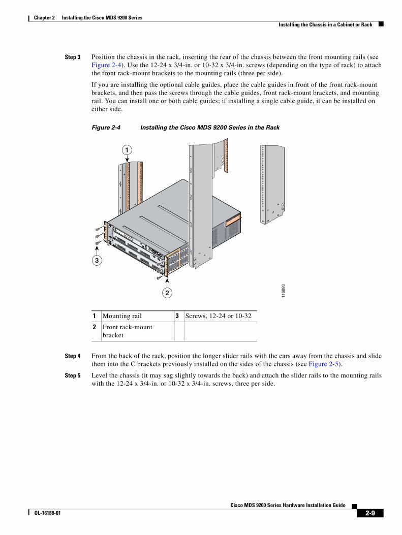
Chapter 2 Installing the Cisco MDS 9200 Series Installing the Chassis in a Cabinet or Rack
Step 3 Position the chassis in the rack, inserting the rear of the chassis between the front mounting rails (see Figure 2-4). Use the 12-24 x 3/4-in. or 10-32 x 3/4-in. screws (depending on the type of rack) to attach the front rack-mount brackets to the mounting rails (three per side).
If you are installing the optional cable guides, place the cable guides in front of the front rack-mount brackets, and then pass the screws through the cable guides, front rack-mount brackets, and mounting rail. You can install one or both cable guides; if installing a single cable guide, it can be installed on either side.
Figure 2-4 Installing the Cisco MDS 9200 Series in the Rack
Step 4 From the back of the rack, position the longer slider rails with the ears away from the chassis and slide them into the C brackets previously installed on the sides of the chassis (see Figure 2-5).
Step 5 Level the chassis (it may sag slightly towards the back) and attach the slider rails to the mounting rails with the 12-24 x 3/4-in. or 10-32 x 3/4-in. screws, three per side.
1 Mounting rail 3 Screws, 12-24 or 10-32
2 Front rack-mount bracket
MDS 9216i
GE1
LINK
GE2
LINK
5
6
7
8
9
10
11
12
13
14
1
2
3
4
1168
93
1
3
2
2-9Cisco MDS 9200 Series Hardware Installation Guide
OL-16188-01
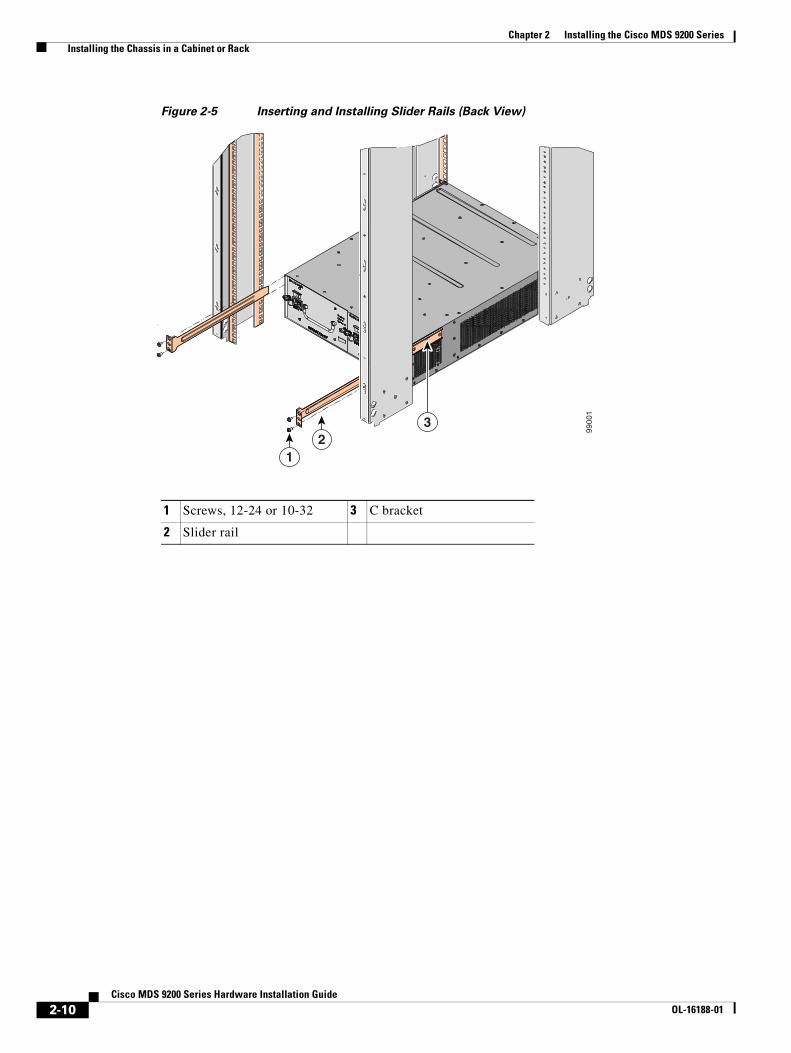
Chapter 2 Installing the Cisco MDS 9200 Series Installing the Chassis in a Cabinet or Rack
Figure 2-5 Inserting and Installing Slider Rails (Back View)
1 Screws, 12-24 or 10-32 3 C bracket
2 Slider rail
9900
1
12
3
2-10Cisco MDS 9200 Series Hardware Installation Guide
OL-16188-01
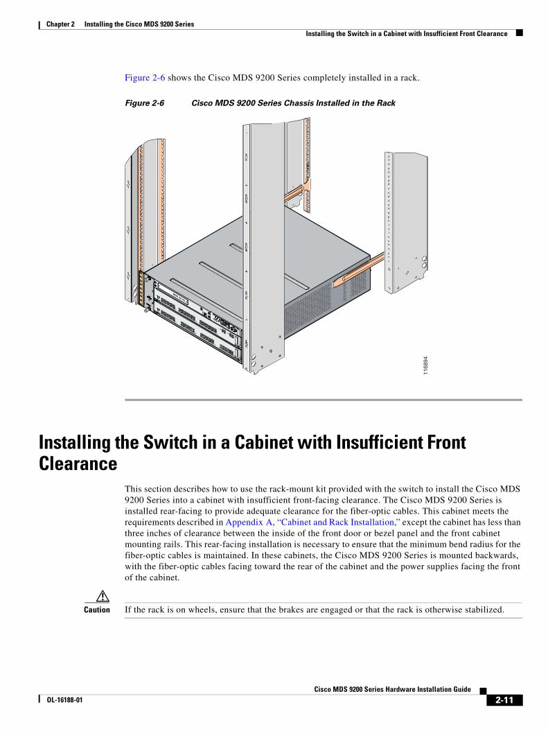
Chapter 2 Installing the Cisco MDS 9200 Series Installing the Switch in a Cabinet with Insufficient Front Clearance
Figure 2-6 shows the Cisco MDS 9200 Series completely installed in a rack.
Figure 2-6 Cisco MDS 9200 Series Chassis Installed in the Rack
Installing the Switch in a Cabinet with Insufficient Front Clearance
This section describes how to use the rack-mount kit provided with the switch to install the Cisco MDS 9200 Series into a cabinet with insufficient front-facing clearance. The Cisco MDS 9200 Series is installed rear-facing to provide adequate clearance for the fiber-optic cables. This cabinet meets the requirements described in Appendix A, “Cabinet and Rack Installation,” except the cabinet has less than three inches of clearance between the inside of the front door or bezel panel and the front cabinet mounting rails. This rear-facing installation is necessary to ensure that the minimum bend radius for the fiber-optic cables is maintained. In these cabinets, the Cisco MDS 9200 Series is mounted backwards, with the fiber-optic cables facing toward the rear of the cabinet and the power supplies facing the front of the cabinet.
Caution If the rack is on wheels, ensure that the brakes are engaged or that the rack is otherwise stabilized.
MDS 9216i
GE1
LINK
GE2
LINK
5
6
7
8
9
10
11
12
13
14
1
2
3
4
1168
94
2-11Cisco MDS 9200 Series Hardware Installation Guide
OL-16188-01
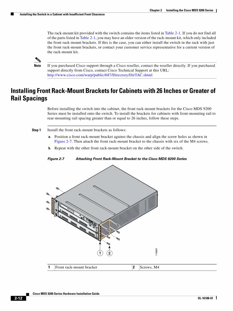
Chapter 2 Installing the Cisco MDS 9200 Series Installing the Switch in a Cabinet with Insufficient Front Clearance
The rack-mount kit provided with the switch contains the items listed in Table 2-1. If you do not find all of the parts listed in Table 2-1, you may have an older version of the rack-mount kit, which only included the front rack-mount brackets. If this is the case, you can either install the switch in the rack with just the front rack-mount brackets, or contact your customer service representative for a current version of the rack-mount kit.
Note If you purchased Cisco support through a Cisco reseller, contact the reseller directly. If you purchased support directly from Cisco, contact Cisco Technical Support at this URL: http://www.cisco.com/warp/public/687/Directory/DirTAC.shtml
Installing Front Rack-Mount Brackets for Cabinets with 26 Inches or Greater of Rail Spacings
Before installing the switch into the cabinet, the front rack-mount brackets for the Cisco MDS 9200 Series must be installed onto the switch. To install the brackets for cabinets with front-mounting rail to rear-mounting rail spacing greater than or equal to 26 inches, follow these steps.
Step 1 Install the front rack-mount brackets as follows:
a. Position a front rack-mount bracket against the chassis and align the screw holes as shown in Figure 2-7. Then attach the front rack-mount bracket to the chassis with six of the M4 screws.
b. Repeat with the other front rack-mount bracket on the other side of the switch.
Figure 2-7 Attaching Front Rack-Mount Bracket to the Cisco MDS 9200 Series
1168
91
MDS 9216i
GE1
LINK
GE2
LINK
5
6
7
8
9
10
11
12
13
14
1
2
3
4
1 2
1 Front rack-mount bracket 2 Screws, M4
2-12Cisco MDS 9200 Series Hardware Installation Guide
OL-16188-01

Chapter 2 Installing the Cisco MDS 9200 Series Installing the Switch in a Cabinet with Insufficient Front Clearance
Step 2 Install the C brackets on the switch as follows:
a. Position one of the C brackets against the side of the switch and align the screw holes as shown in Figure 2-8 and Figure 2-9. Then attach the bracket to the switch with two of the flat-head M4 screws.
Figure 2-8 Installing C Brackets onto the Cisco MDS 9200 Series
1 C bracket 2 Screws, M4
MDS 9216i
GE1
LINK
GE2
LINK
5
6
7
8
9
10
11
12
13
14
1
2
3
4
1168
92
1 2
2-13Cisco MDS 9200 Series Hardware Installation Guide
OL-16188-01
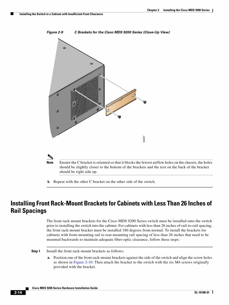
Chapter 2 Installing the Cisco MDS 9200 Series Installing the Switch in a Cabinet with Insufficient Front Clearance
Figure 2-9 C Brackets for the Cisco MDS 9200 Series (Close-Up View)
Note Ensure the C bracket is oriented so that it blocks the fewest airflow holes on the chassis; the holes should be slightly closer to the bottom of the brackets and the text on the back of the bracket should be right side up.
b. Repeat with the other C bracket on the other side of the switch.
Installing Front Rack-Mount Brackets for Cabinets with Less Than 26 Inches of Rail Spacings
The front rack-mount brackets for the Cisco MDS 9200 Series switch must be installed onto the switch prior to installing the switch into the cabinet. For cabinets with less than 26 inches of rail-to-rail spacing, the front rack-mount bracket must be installed 180 degrees from normal. To install the brackets for cabinets with front-mounting rail to rear-mounting rail spacing of less than 26 inches that need to be mounted backwards to maintain adequate fiber-optic clearance, follow these steps:
Step 1 Install the front rack-mount brackets as follows:
a. Position one of the front rack-mount brackets against the side of the switch and align the screw holes as shown in Figure 2-10. Then attach the bracket to the switch with the six M4 screws originally provided with the bracket.
9429
7
2-14Cisco MDS 9200 Series Hardware Installation Guide
OL-16188-01

Chapter 2 Installing the Cisco MDS 9200 Series Installing the Switch in a Cabinet with Insufficient Front Clearance
Figure 2-10 Front Rack-Mount Brackets (Rotated) Installed on the Cisco MDS 9200 Series
b. Repeat with the other front rack-mount bracket on the other side of the switch.
Step 2 Install the C brackets on the switch as follows:
a. Position one of the C brackets against the side of the switch and align the screw holes as shown in Figure 2-11 and Figure 2-12. Then attach the bracket to the switch with two of the flat-head M4 screws.
Figure 2-11 Installing C Brackets onto the Cisco MDS 9200 Series
MDS 9216i
1168
95
LINK-
GE1GE2
1 2 3 4
LINK-10 11 12 13 14
5 6 7 8 9
1 C bracket 2 Screws, M4
MDS 9216i
GE1
LINK
GE2
LINK
5
6
7
8
9
10
11
12
13
14
1
2
3
4
1168
96
1 2
2-15Cisco MDS 9200 Series Hardware Installation Guide
OL-16188-01
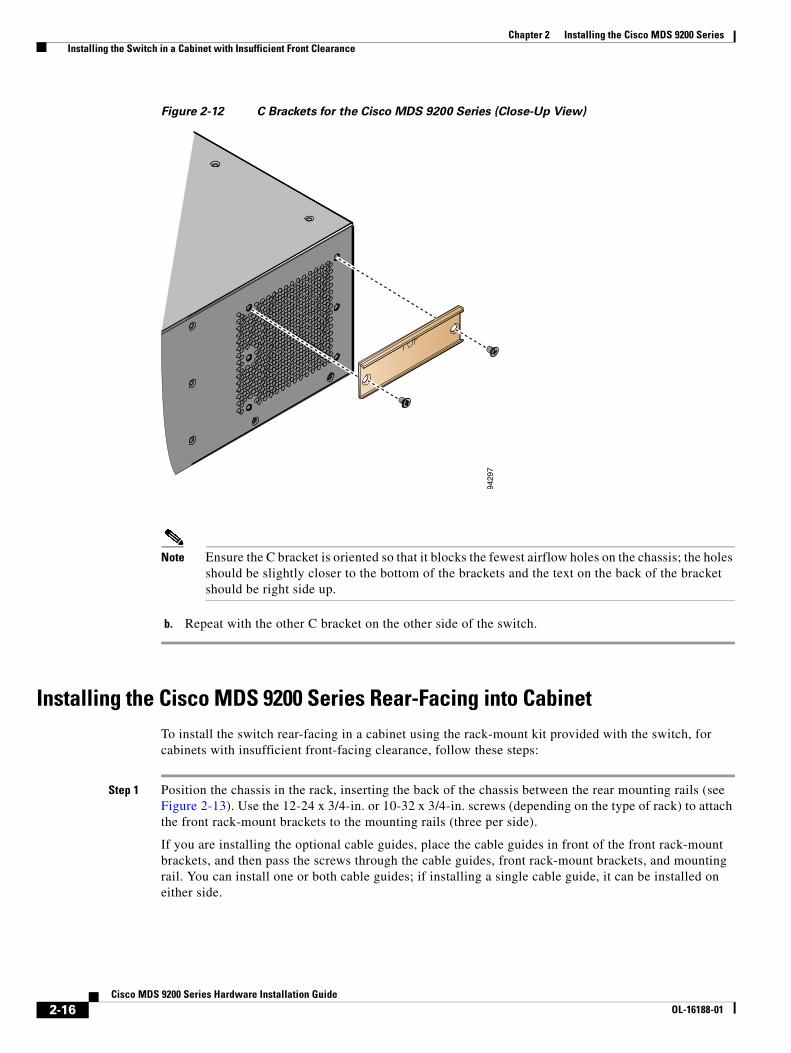
Chapter 2 Installing the Cisco MDS 9200 Series Installing the Switch in a Cabinet with Insufficient Front Clearance
Figure 2-12 C Brackets for the Cisco MDS 9200 Series (Close-Up View)
Note Ensure the C bracket is oriented so that it blocks the fewest airflow holes on the chassis; the holes should be slightly closer to the bottom of the brackets and the text on the back of the bracket should be right side up.
b. Repeat with the other C bracket on the other side of the switch.
Installing the Cisco MDS 9200 Series Rear-Facing into CabinetTo install the switch rear-facing in a cabinet using the rack-mount kit provided with the switch, for cabinets with insufficient front-facing clearance, follow these steps:
Step 1 Position the chassis in the rack, inserting the back of the chassis between the rear mounting rails (see Figure 2-13). Use the 12-24 x 3/4-in. or 10-32 x 3/4-in. screws (depending on the type of rack) to attach the front rack-mount brackets to the mounting rails (three per side).
If you are installing the optional cable guides, place the cable guides in front of the front rack-mount brackets, and then pass the screws through the cable guides, front rack-mount brackets, and mounting rail. You can install one or both cable guides; if installing a single cable guide, it can be installed on either side.
9429
7
2-16Cisco MDS 9200 Series Hardware Installation Guide
OL-16188-01
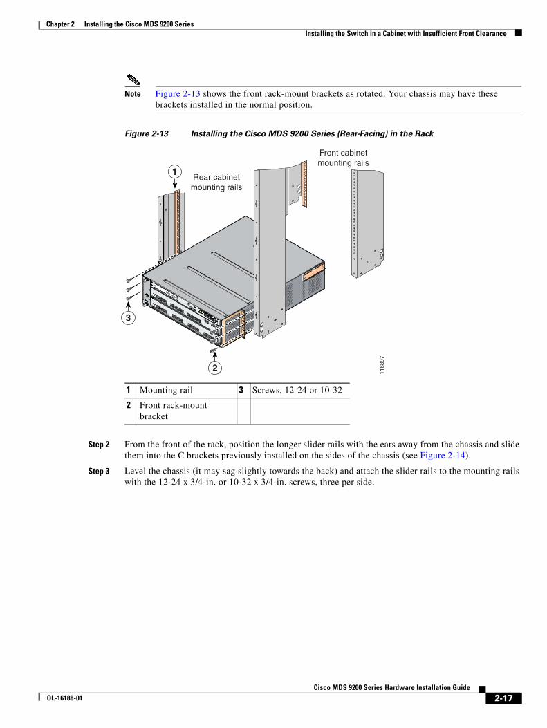
Chapter 2 Installing the Cisco MDS 9200 Series Installing the Switch in a Cabinet with Insufficient Front Clearance
Note Figure 2-13 shows the front rack-mount brackets as rotated. Your chassis may have these brackets installed in the normal position.
Figure 2-13 Installing the Cisco MDS 9200 Series (Rear-Facing) in the Rack
Step 2 From the front of the rack, position the longer slider rails with the ears away from the chassis and slide them into the C brackets previously installed on the sides of the chassis (see Figure 2-14).
Step 3 Level the chassis (it may sag slightly towards the back) and attach the slider rails to the mounting rails with the 12-24 x 3/4-in. or 10-32 x 3/4-in. screws, three per side.
1 Mounting rail 3 Screws, 12-24 or 10-32
2 Front rack-mount bracket
MDS 9216i
GE1
LINK
GE2
LINK
5
6
7
8
9
10
11
12
13
14
1
2
3
4
1168
97
1
3
2
Front cabinetmounting rails
Rear cabinetmounting rails
2-17Cisco MDS 9200 Series Hardware Installation Guide
OL-16188-01
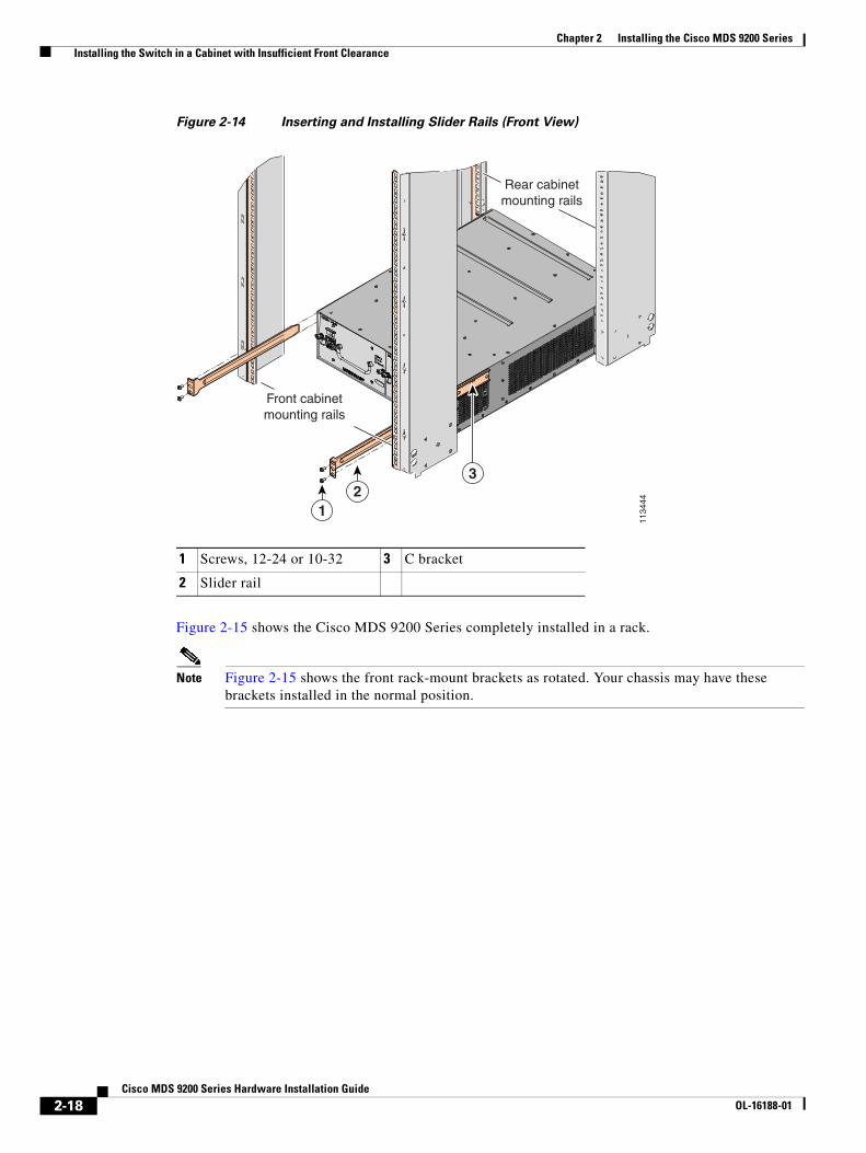
Chapter 2 Installing the Cisco MDS 9200 Series Installing the Switch in a Cabinet with Insufficient Front Clearance
Figure 2-14 Inserting and Installing Slider Rails (Front View)
Figure 2-15 shows the Cisco MDS 9200 Series completely installed in a rack.
Note Figure 2-15 shows the front rack-mount brackets as rotated. Your chassis may have these brackets installed in the normal position.
1 Screws, 12-24 or 10-32 3 C bracket
2 Slider rail
1134
44
12
3
Rear cabinetmounting rails
Front cabinetmounting rails
2-18Cisco MDS 9200 Series Hardware Installation Guide
OL-16188-01

Chapter 2 Installing the Cisco MDS 9200 Series System Grounding
Figure 2-15 Cisco MDS 9200 Series Installed in the Rack (Back View)
System GroundingThis section describes the need for system grounding and explains how to prevent damage from electrostatic discharge.
Proper Grounding PracticesGrounding is one of the most important parts of equipment installation. Proper grounding practices ensure that the buildings and the installed equipment within them have low-impedance connections and low-voltage differentials between chassis. When you properly ground systems during installation, you reduce or prevent shock hazards, equipment damage due to transients, and data corruption. Table 2-2 lists some general grounding practice guidelines.
1168
98
MDS 9216i
GE1
LINK
GE2
LINK
5
6
7
8
9
10
11
12
13
14
1
2
3
4
Rear cabinetmounting rails
Front cabinetmounting rails
2-19Cisco MDS 9200 Series Hardware Installation Guide
OL-16188-01

Chapter 2 Installing the Cisco MDS 9200 Series System Grounding
Table 2-2 Grounding Best Practices
EnvironmentElectromagnetic Noise Severity Level Grounding Recommendations
Commercial building is subjected to direct lightning strikes.
For example, some places in the United States, such as Florida, are subject to more lightning strikes than other areas.
High All lightning protection devices must be installed in strict accordance with manufacturer recommendations. Conductors carrying lightning current should be spaced away from power and data lines in accordance with applicable recommendations and codes. Best grounding practices must be closely followed.
Commercial building is located in an area where lightning storms frequently occur but is not subject to direct lightning strikes.
High Best grounding practices must be closely followed.
Commercial building contains a mix of information technology equipment and industrial equipment, such as welding.
Medium to high Best grounding practices must be closely followed.
Existing commercial building is not subject to natural environmental noise or man-made industrial noise. This building contains a standard office environment. This installation has a history of malfunction due to electromagnetic noise.
Medium Best grounding practices must be closely followed. Determine source and cause of noise if possible, and mitigate as closely as possible at the noise source or reduce coupling from the noise source to the victim equipment.
New commercial building is not subject to natural environmental noise or man-made industrial noise. This building contains a standard office environment.
Low Best grounding practices should be followed as closely as possible. Electromagnetic noise problems are not anticipated, but installing a best practice grounding system in a new building is often the least expensive route and the best way to plan for the future.
Existing commercial building is not subject to natural environmental noise or man-made industrial noise. This building contains a standard office environment.
Low Best grounding practices should be followed as much as possible. Electromagnetic noise problems are not anticipated, but installing a best practice grounding system is always recommended.
2-20Cisco MDS 9200 Series Hardware Installation Guide
OL-16188-01
Chapter 2 Installing the Cisco MDS 9200 Series System Grounding
Note In all situations, grounding practices must comply with local National Electric Code (NEC) requirements or local laws and regulations.
Note Always ensure that all of the modules are completely installed and that the captive installation screws are fully tightened. In addition, ensure that all I/O cables and power cords are properly seated. These practices are normal installation practices and must be followed in all installations.
Preventing Electrostatic Discharge DamageElectrostatic discharge (ESD) damage, which can occur when modules or other FRUs are improperly handled, results in intermittent or complete failures. Modules consist of printed circuit boards that are fixed in metal carriers. Electromagnetic interference (EMI) shielding and connectors are integral components of the carrier. Although the metal carrier helps to protect the board from ESD, always use an ESD grounding strap when handling modules.
Follow these guidelines for preventing ESD damage:
• Always use an ESD wrist strap and ensure that it makes maximum contact with bare skin. ESD grounding straps are available with banana plugs, metal spring clips, or alligator clips. All MDS 9200 series chassis are equipped with a banana plug connector (identified by the ground symbol next to the connector) somewhere on the front panel. Cisco recommends that you use a personal ESD grounding strap equipped with a banana plug.
• If you choose to use the disposable ESD wrist strap supplied with most FRUs or an ESD wrist strap equipped with an alligator clip, you must attach the system ground lug to the chassis in order to provide a proper grounding point for the ESD wrist strap.
Note This system ground is also referred to as the network equipment building system (NEBS) ground.
• If your chassis does not have the system ground attached, you must install the system ground lug. See “Establishing the System Ground” section on page 2-23 for installation instructions and location of the chassis system ground pads.
Note You do not need to attach a supplemental system ground wire to the system ground lug; the lug provides a direct path to the bare metal of the chassis.
After you install the system ground lug, follow these steps to correctly attach the ESD wrist strap:
Step 1 Attach the ESD wrist strap to bare skin as follows:
c. If you are using the ESD wrist strap supplied with the FRUs, open the wrist strap package and unwrap the ESD wrist strap. Place the black conductive loop over your wrist and tighten the strap so that it makes good contact with your bare skin.
d. If you are using an ESD wrist strap equipped with an alligator clip, open the package and remove the ESD wrist strap. Locate the end of the wrist strap that attaches to your body and secure it to your bare skin.
2-21Cisco MDS 9200 Series Hardware Installation Guide
OL-16188-01
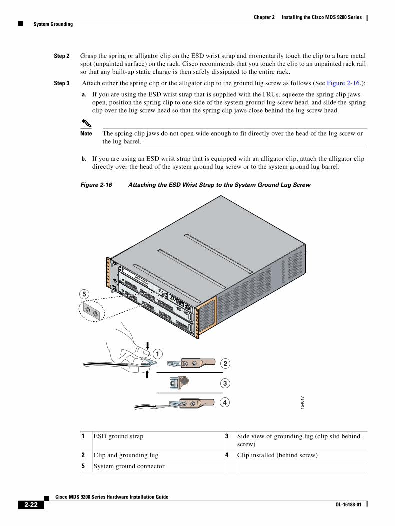
Chapter 2 Installing the Cisco MDS 9200 Series System Grounding
Step 2 Grasp the spring or alligator clip on the ESD wrist strap and momentarily touch the clip to a bare metal spot (unpainted surface) on the rack. Cisco recommends that you touch the clip to an unpainted rack rail so that any built-up static charge is then safely dissipated to the entire rack.
Step 3 Attach either the spring clip or the alligator clip to the ground lug screw as follows (See Figure 2-16.):
a. If you are using the ESD wrist strap that is supplied with the FRUs, squeeze the spring clip jaws open, position the spring clip to one side of the system ground lug screw head, and slide the spring clip over the lug screw head so that the spring clip jaws close behind the lug screw head.
Note The spring clip jaws do not open wide enough to fit directly over the head of the lug screw or the lug barrel.
b. If you are using an ESD wrist strap that is equipped with an alligator clip, attach the alligator clip directly over the head of the system ground lug screw or to the system ground lug barrel.
Figure 2-16 Attaching the ESD Wrist Strap to the System Ground Lug Screw
MDS 9216i
GE1
LINK
GE2
LINK
5
6
7
8
9
10
11
12
13
14
1
2
3
4
1540
17
21
3
4
5
1 ESD ground strap 3 Side view of grounding lug (clip slid behind screw)
2 Clip and grounding lug 4 Clip installed (behind screw)
5 System ground connector
2-22Cisco MDS 9200 Series Hardware Installation Guide
OL-16188-01

Chapter 2 Installing the Cisco MDS 9200 Series System Grounding
In addition, follow these guidelines when handling modules:
• Handle carriers by available handles or edges only; avoid touching the printed circuit boards or connectors.
• Place a removed component board-side-up on an antistatic surface or in a static shielding container. If you plan to return the component to the factory, immediately place it in a static shielding container.
• Never attempt to remove the printed circuit board from the metal carrier.
Caution For safety, periodically check the resistance value of the antistatic strap. The measurement should be between 1 and 10 megohm (Mohm).
Establishing the System GroundThis section describes how to connect a system ground to the MDS 9200 series switches.
Note This system ground is also referred to as the network equipment building system (NEBS) ground.
You must use the system (NEBS) ground on AC-powered systems if you are installing this equipment in a U.S. or European Central Office.
The system (NEBS) ground provides additional grounding for EMI shielding requirements and grounding for the low voltage supplies (DC-DC converters) on the modules and is intended to satisfy the telcordia Technologies NEBS requirements for supplemental bonding and grounding connections. You must observe the following system grounding guidelines for your chassis:
• You must install the system (NEBS) ground connection with any other rack or system power ground connections that you make. The system ground connection is required if this equipment is installed in a U.S. or European Central Office.
• You must connect both the system (NEBS) ground connection and the power supply ground connection to an earth ground. The system (NEBS) ground connection is required if this equipment is installed in a U.S. or European Central Office.
• You do not need to power down the chassis because the MDS 9200 series chassis are equipped with AC-input power supplies.
Required Tools and EquipmentTo connect the ground system, you need the following tools and materials:
• Grounding lug—A two holes standard barrel lug. Supports up to 6 AWG wire. Supplied as part of accessory kit.
• Grounding screws—Two M4 x 8mm (metric) pan-head screws. Supplied as part of the accessory kit.
• Grounding wire—Not supplied as part of accessory kit. The grounding wire should be sized according to local and national installation requirements. Depending on the power supply and system, a 12 AWG to 6 AWG copper conductor is required for U.S. installations. Commercially available 6 AWG wire is recommended. The length of the grounding wire depends on the proximity of the switch to proper grounding facilities.
• No. 1 Phillips screwdriver.
2-23Cisco MDS 9200 Series Hardware Installation Guide
OL-16188-01

Chapter 2 Installing the Cisco MDS 9200 Series Grounding the Chassis
• Crimping tool to crimp the grounding wire to the grounding lug.
• Wire-stripping tool to remove the insulation from the grounding wire.
Grounding the ChassisThe chassis has a grounding pad with two threaded M4 holes for attaching a grounding lug. Figure 2-17 shows the system ground location on the Cisco MDS 9200 Series.
Warning When installing or replacing the unit, the ground connection must always be made first and disconnected last. Statement 1046
Caution Cisco recommends grounding the chassis, even if the rack is already grounded.
Caution All power supplies must be grounded. The receptacles of the AC power cables used to provide power to the chassis must be the grounding type, and the grounding conductors should connect to protective earth ground at the service equipment.
2-24Cisco MDS 9200 Series Hardware Installation Guide
OL-16188-01
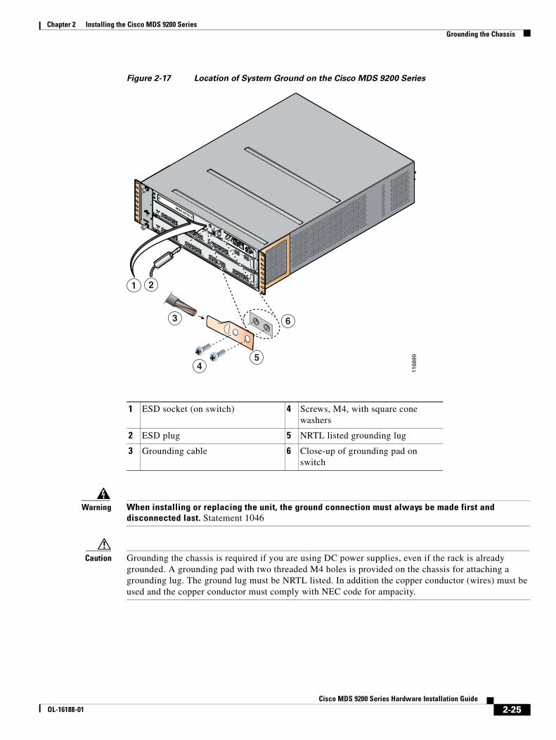
Chapter 2 Installing the Cisco MDS 9200 Series Grounding the Chassis
Figure 2-17 Location of System Ground on the Cisco MDS 9200 Series
Warning When installing or replacing the unit, the ground connection must always be made first and disconnected last. Statement 1046
Caution Grounding the chassis is required if you are using DC power supplies, even if the rack is already grounded. A grounding pad with two threaded M4 holes is provided on the chassis for attaching a grounding lug. The ground lug must be NRTL listed. In addition the copper conductor (wires) must be used and the copper conductor must comply with NEC code for ampacity.
1 ESD socket (on switch) 4 Screws, M4, with square cone washers
2 ESD plug 5 NRTL listed grounding lug
3 Grounding cable 6 Close-up of grounding pad on switch
MDS 9216i
GE1
LINK
GE2
LINK
5
6
7
8
9
10
11
12
13
14
1
2
3
4
1168
99
2
3
45
6
1
2-25Cisco MDS 9200 Series Hardware Installation Guide
OL-16188-01
Chapter 2 Installing the Cisco MDS 9200 Series Starting Up the Switch
To attach the grounding lug and cable to the chassis, follow these steps:
Step 1 Use a wire-stripping tool to remove approximately 0.75 in. (19 mm) of the covering from the end of the grounding cable.
Step 2 Insert the stripped end of the grounding cable into the open end of the grounding lug.
Step 3 Use the crimping tool to secure the grounding cable in the grounding lug.
Step 4 Remove the adhesive label from the grounding pad on the chassis.
Step 5 Place the grounding lug against the grounding pad so that there is solid metal-to-metal contact, and insert the two M4 screws with washers through the holes in the grounding lug and into the grounding pad.
Step 6 Ensure that the lug and cable do not interfere with other equipment.
Step 7 Prepare the other end of the grounding cable and connect it to an appropriate grounding point in your site to ensure adequate earth ground.
Starting Up the SwitchThis section provides instructions for powering up the switch and verifying component installation.
Warning Hazardous voltage or energy is present on the backplane when the system is operating. Use caution when servicing. Statement 1034
Warning Blank faceplates and cover panels serve three important functions: they prevent exposure to hazardous voltages and currents inside the chassis; they contain electromagnetic interference (EMI) that might disrupt other equipment; and they direct the flow of cooling air through the chassis. Do not operate the system unless all cards, faceplates, front covers, and rear covers are in place. During this procedure, wear grounding wrist straps to avoid ESD damage to the switch. Statement 1029
Note Do not connect the MGMT 10/100 Ethernet port to the LAN until the initial switch configuration has been performed. For instructions on configuring the switch, see the Cisco MDS 9000 Family CLI Configuration Guide or the Cisco MDS 9000 Family Fabric Manager Configuration Guide. For instructions on connecting to the console port, see the “Connecting to the Console Port” section on page 3-2.
Warning When installing or replacing the unit, the ground connection must always be made first and disconnected last. Statement 1046
To power up the switch and verify hardware operation, follow these steps:
Step 1 Verify that empty module slots have filler panels installed, the faceplates of all modules are flush with the front of the chassis, the ejector levers are fully closed and approximately parallel to the front of the module, and the captive screws of the power supplies, fan module, and all supervisor, switching, or services modules are tight.
2-26Cisco MDS 9200 Series Hardware Installation Guide
OL-16188-01
Chapter 2 Installing the Cisco MDS 9200 Series Starting Up the Switch
Step 2 Verify that both power supplies and the fan module are installed.
Step 3 Verify that the power switches on both power supplies are off, and then plug the power cables into the power supplies and tighten the screws on the power cable retainers to ensure the cables cannot be pulled out.
Note Depending on the outlet receptacle on your power distribution unit, you may need the optional jumper power cord to connect the Cisco MDS 9200 Series to your outlet receptacle. See the “Jumper Power Cord” section on page C-11.
Step 4 Connect the other end of the power cables to an AC power source.
Step 5 Ensure that the switch is adequately grounded as described in the “Installing the Switch in a Cabinet with Insufficient Front Clearance” section on page 2-11, and that the power cables are connected to outlets that have the required AC power voltages (see the “Weight of Modules” section on page B-3).
Step 6 Flip the power switches on the power supplies to the on (|) position. The switch boots automatically.
Step 7 Listen for the fans; they should begin operating when the switch is powered on.
Caution Do not operate the switch without a functioning fan module except for during the brief fan module replacement procedure. Cisco MDS 9000 Family switches can operate for only a few minutes without any functioning fan modules before they begin to overheat.
Step 8 After the switch boots, verify that the LED behavior is as follows:
• Fan module: Status LED is green.
• Power supplies:
– Input Ok LED is green.
– Fan Ok LED is green.
– Output Fail LED is off.
• Supervisor, switching, or services modules:
– During initialization, the status LED on the module flashes orange once, remains orange during diagnostic boot tests, then turns green when the module is operational (online). If the system software is unable to start up, this LED remains orange or turns red.
– After initialization, the status LED is green, indicating that all chassis environmental monitors are reporting that the system is operational. If this LED is orange or red, then one or more environmental monitor is reporting a problem.
• The Link LEDs for the Ethernet port should not be on unless the cable is connected.
Note The link LEDs for the Fibre Channel ports remain yellow until the ports are enabled, and the LED for the MGMT 10/100 Ethernet port remains off until the port is connected.
Step 9 Try removing and reinstalling a component that is not operating correctly. If it still does not operate correctly, contact your customer service representative for a replacement.
2-27Cisco MDS 9200 Series Hardware Installation Guide
OL-16188-01

Chapter 2 Installing the Cisco MDS 9200 Series Removing and Installing Components
Note If you purchased this product through a Cisco reseller, contact the reseller directly for technical support. If you purchased this product directly from Cisco, contact Cisco Technical Support at this URL: http://www.cisco.com/warp/public/687/Directory/DirTAC.shtml.
Step 10 Verify that the system software has booted and the switch has initialized without error messages. If any problems occur, see the Cisco MDS 9000 Family Troubleshooting Guide or the Cisco MDS 9000 Family System Messages Guide. If you cannot resolve an issue, contact your customer service representative.
Step 11 Complete the worksheets provided in Appendix D, “Site Planning and Maintenance Records” for future reference.
Note A setup utility automatically launches the first time you access the switch and guides you through the basic configuration. For instructions on how to configure the switch and check module connectivity, see the Cisco MDS 9000 Family CLI Configuration Guide or the Cisco MDS 9000 Family Fabric Manager Configuration Guide.
Removing and Installing ComponentsThis section includes the following topics:
• Removing and Installing Switching and Services Modules, page 2-28
• Maintaining a Caching Services Module, page 2-35
• Removing and Installing Power Supplies, page 2-36
• Removing and Installing the Fan Module, page 2-38
• Removing the Cisco MDS 9200 Series, page 2-40
Warning Hazardous voltage or energy is present on the backplane when the system is operating. Use caution when servicing. Statement 1034
Caution To prevent ESD damage, wear grounding wrist straps during these procedures and handle modules by the carrier edges only.
Removing and Installing Switching and Services ModulesSlot 1 is reserved for the supervisor module with its integrated multiport switching or IP services module. Slot 2 can contain an optional module. See Figure 1-2 for slot locations.
Warning Invisible laser radiation may be emitted from disconnected fibers or connectors. Do not stare into beams or view directly with optical instruments. Statement 1051
2-28Cisco MDS 9200 Series Hardware Installation Guide
OL-16188-01
Chapter 2 Installing the Cisco MDS 9200 Series Removing and Installing Components
Warning Use of controls, adjustments, or performing procedures other than those specified may result in hazardous radiation exposure. Statement 1057
Warning Hazardous voltage or energy is present on the backplane when the system is operating. Use caution when servicing. Statement 1034
Caution To prevent ESD damage, wear grounding wrist straps during these procedures and handle modules by the carrier edges only.
Note Install the Cisco MDS 9200 Series in the rack before installing modules. For information about installing the chassis, see the “Installing the Chassis in a Cabinet or Rack” section on page 2-5.
This section includes the following topics:
• Removing a Caching Services Module, page 2-31
• Removing Other Switching or Services Modules, page 2-32
• Installing a Switching or Services Module, Including Caching Services Modules, page 2-33
• Verifying Installation of a Switching or Services Module, page 2-34
Figure 2-18 and Figure 2-19 show the positioning of a module in the chassis.
2-29Cisco MDS 9200 Series Hardware Installation Guide
OL-16188-01
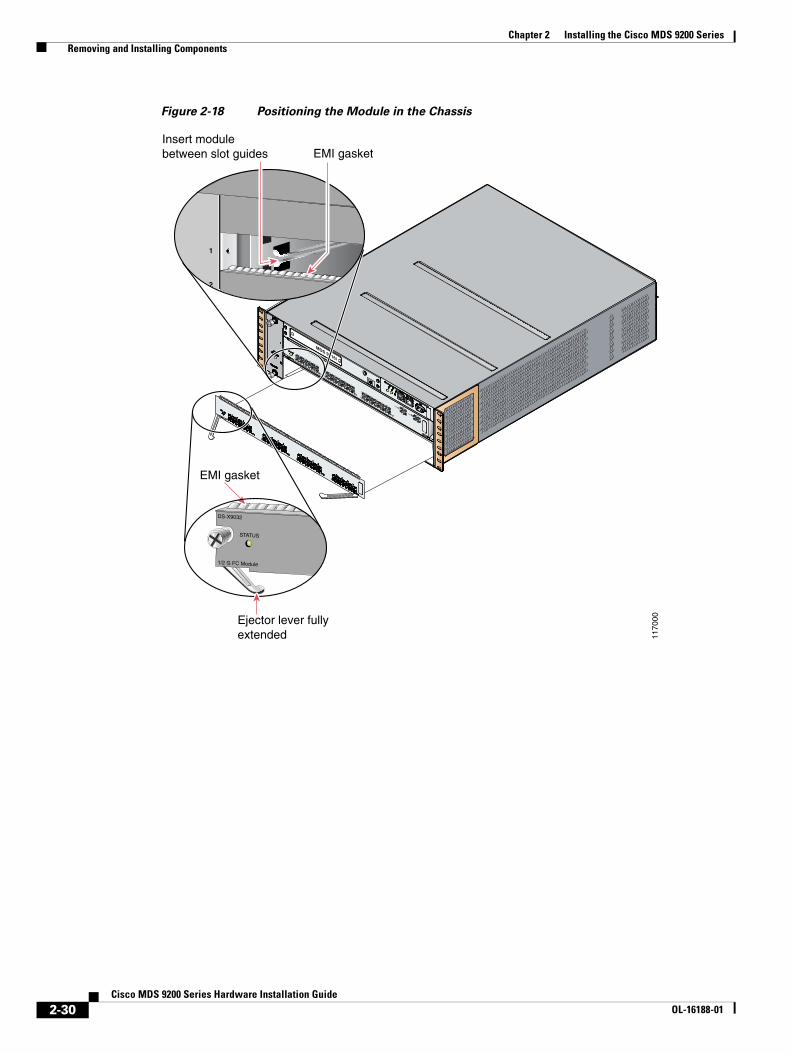
Chapter 2 Installing the Cisco MDS 9200 Series Removing and Installing Components
Figure 2-18 Positioning the Module in the Chassis
MDS 9216i
GE1
LINK
GE2
LINK
5
6
7
8
9
10
11
12
13
14
1
2
3
4
EMI gasket
STATUS
DS-X9032
1/2 G FC Module
EMI gasketInsert module between slot guides
4
3
2
1
6
1170
00Ejector lever fully extended
2-30Cisco MDS 9200 Series Hardware Installation Guide
OL-16188-01
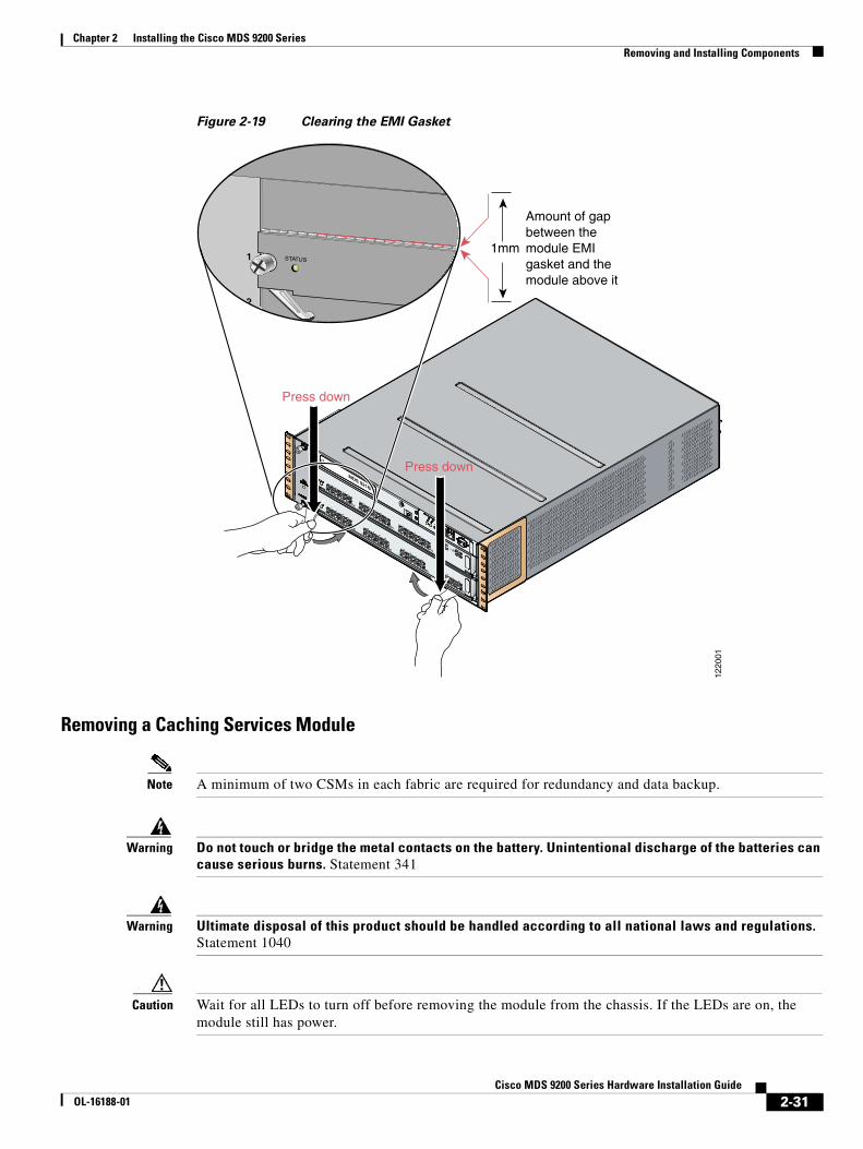
Chapter 2 Installing the Cisco MDS 9200 Series Removing and Installing Components
Figure 2-19 Clearing the EMI Gasket
Removing a Caching Services Module
Note A minimum of two CSMs in each fabric are required for redundancy and data backup.
Warning Do not touch or bridge the metal contacts on the battery. Unintentional discharge of the batteries can cause serious burns. Statement 341
Warning Ultimate disposal of this product should be handled according to all national laws and regulations. Statement 1040
Caution Wait for all LEDs to turn off before removing the module from the chassis. If the LEDs are on, the module still has power.
MDS 9216i
GE1
LINK
GE2
LINK
5
6
7
8
9
10
11
12
13
14
1
2
3
4
1220
01
1mm
Amount of gap between the module EMI gasket and the module above it
2
1
Press down
Press down
STATUS
2-31Cisco MDS 9200 Series Hardware Installation Guide
OL-16188-01

Chapter 2 Installing the Cisco MDS 9200 Series Removing and Installing Components
To remove a CSM module from the chassis, follow these steps:
Step 1 Power off the module from the CLI. For information about the correct command to use, see the Cisco MDS 9000 Family CLI Configuration Guide.
Step 2 Ensure that the backup process has completed by verifying that all LEDs on the module have turned off. This requires up to 10 minutes.
Step 3 Loosen the two captive screws on the module.
Step 4 Remove the module from the chassis as follows:
a. Place your thumbs on the left and right ejector levers (shown in Figure 2-18 on page 2-30) and simultaneously rotate the levers outward to unseat the module from the backplane connector.
b. Grasp the front edge of the module and slide the module part of the way out of the slot. Place your other hand under the module to support the weight of the module. Do not touch the module circuitry.
Step 5 Place the module on an antistatic mat or antistatic foam if not immediately reinstalling it in another slot.
Step 6 Install a filler panel to keep dust out of the chassis and maintain consistent airflow if the slot will remain empty.
Warning Blank faceplates and cover panels serve three important functions: they prevent exposure to hazardous voltages and currents inside the chassis; they contain electromagnetic interference (EMI) that might disrupt other equipment; and they direct the flow of cooling air through the chassis. Do not operate the system unless all cards, faceplates, front covers, and rear covers are in place. Statement 1029
Removing Other Switching or Services Modules
To remove a switching or services module from the chassis, follow these steps:
Step 1 Disconnect any network interface cables attached to the module.
Step 2 Loosen the two captive screws on the module.
Step 3 Remove the module from the chassis as follows:
a. Place your thumbs on the left and right ejector levers (shown in Figure 2-18 on page 2-30) and simultaneously rotate the levers outward to unseat the module from the backplane connector.
b. Grasp the front edge of the module and slide the module part of the way out of the slot. Place your other hand under the module to support the weight of the module. Do not touch the module circuitry.
Step 4 Place the module on an antistatic mat or antistatic foam if not immediately reinstalling it in another slot.
Step 5 Install a filler panel to keep dust out of the chassis and maintain consistent airflow if the slot will remain empty.
2-32Cisco MDS 9200 Series Hardware Installation Guide
OL-16188-01

Chapter 2 Installing the Cisco MDS 9200 Series Removing and Installing Components
Warning Blank faceplates and cover panels serve three important functions: they prevent exposure to hazardous voltages and currents inside the chassis; they contain electromagnetic interference (EMI) that might disrupt other equipment; and they direct the flow of cooling air through the chassis. Do not operate the system unless all cards, faceplates, front covers, and rear covers are in place. Statement 1029
Installing a Switching or Services Module, Including Caching Services Modules
The following warning applies only to the Caching Services Module:
Warning Do not touch or bridge the metal contacts on the battery. Unintentional discharge of the batteries can cause serious burns. Statement 341
Note Before installing any modules in the chassis, Cisco recommends installing the chassis in the rack. See the “Installing the Chassis in a Cabinet or Rack” section on page 2-5.
To install a module in slot 2 of the chassis, follow these steps:
Step 1 Verify that there is enough clearance to accommodate any interface equipment that you connect directly to the nearby components.
Step 2 If a filler panel is installed, remove the two Phillips pan-head screws from the filler panel and remove the panel. To remove a currently installed module, see the “Removing and Installing Switching and Services Modules” section on page 2-28.
Step 3 Open fully both ejector levers on the new or replacement module (see Figure 2-18 on page 2-30).
Step 4 Position the module in the chassis as follows:
a. Position the module in the slot, aligning the sides of the module carrier with the slot guides on each side of the slot.
b. Slide the module carefully into the slot until the EMI gasket along the top edge of the module makes contact with the supervisor module above it and both ejector levers have closed to approximately 45 degrees with respect to the module faceplate (see Figure 2-19 on page 2-31).
c. Grasp the two ejector levers using the thumb and forefinger of each hand and press down to create a small 0.040-in. (1 mm) gap between the module's EMI gasket and the module above it (see Figure 2-20).
2-33Cisco MDS 9200 Series Hardware Installation Guide
OL-16188-01

Chapter 2 Installing the Cisco MDS 9200 Series Removing and Installing Components
Figure 2-20 Closing the Ejector Levers
Caution Do not press down too forcefully on the levers because they can bend.
d. Press down and simultaneously close the left and right ejector levers to fully seat the module in the backplane connector. The ejector levers are fully closed when they are flush with the module faceplate.
Note Ensure that the ejector levers are fully closed before tightening the captive screws. Failure to fully seat the module in the backplane connector can result in error messages.
e. Tighten the two captive screws on the module.
Verifying Installation of a Switching or Services Module
To verify the module installation in slot 2, follow these steps:
Step 1 Verify that the ejector levers of the module are fully closed (parallel to the faceplate) to ensure that the module is fully seated in the backplane connectors.
Step 2 Check the captive screws of the module, the power supply, and the fan module, and tighten any loose captive screws.
Step 3 Verify that a filler panel is installed and that the screws holding the panel in place are tightened if the slot is to remain empty.
Step 4 Turn on the power supply switches to power up the system and check the LEDs on the module.
Note For information on how to check connectivity of the module, see the Cisco MDS 9000 Family CLI Configuration Guide or the Cisco MDS 9000 Family Fabric Manager Configuration Guide.
FANSTATUS
FAN-MOD-2
1
2
1220
03
Ejector levers flush withmodule faceplate
1 2 3 4 5 6 7 8 9 10 11 12 13 14 15 16
STAT
US
SYST
EM
RES
ET CONSOLE MGMT 10/100
MDS 9216iCOM1
—SPEED LINK—
LINK-
—SPEEDLINK—
STATUS
1 5 6 7 8 9
LINK— —SPEED
10 11 12 13 142 3 4
GE1
LINK-
GE2
2-34Cisco MDS 9200 Series Hardware Installation Guide
OL-16188-01

Chapter 2 Installing the Cisco MDS 9200 Series Removing and Installing Components
Maintaining a Caching Services Module
Caution Maintenance should only be performed by qualified service personnel.
Note A minimum of two CSMs in each fabric are required for redundancy and data backup.
This section includes the following topics:
• Maintaining the Batteries on the Caching Services Module, page 2-35
• Maintaining the Disk Drives on the Caching Services Module, page 2-35
Maintaining the Batteries on the Caching Services Module
The CSM batteries last approximately three years. The following message displays in the system log when a battery fails:
Dec 5 17:14:36 sw-90.21 %SVC_BATTERY-SLOT8-4-BATTERY_CAPACITY_LOW: Battery capacity is below the required threshold.
A message also appears in the output of the show interface command.
If you see this message, contact your support provider for assistance. If a battery fails, the CSM must be replaced.
Caution The CSM batteries are shipped fully charged and should be handled accordingly.
Warning Do not touch or bridge the metal contacts on the battery. Unintentional discharge of the batteries can cause serious burns. Statement 341
Warning Ultimate disposal of this product should be handled according to all national laws and regulations. Statement 1040
The batteries are automatically charged on a periodic basis with an SMBus-compliant Level III smart charger located on the CSM. The smart charger measures the charge and recharges the battery to full if it is less than 90 percent of capacity.
The batteries are also automatically reconditioned on a periodic basis, one battery at a time. During reconditioning all power is drained from the battery and the battery is completely recharged, requiring approximately six hours. The Battery Status LED flashes green during the reconditioning.
Maintaining the Disk Drives on the Caching Services Module
A message displays in the system log when a disk drive requires replacement. If you see this message, contact your support provider for assistance.
If a disk drive fails, the CSM must be replaced. The other CSM(s) in the fabric contain the same data, and they can continue to provide caching services during the replacement period.
2-35Cisco MDS 9200 Series Hardware Installation Guide
OL-16188-01
Chapter 2 Installing the Cisco MDS 9200 Series Removing and Installing Components
Removing and Installing Power SuppliesThe Cisco MDS 9200 Series supports dual 845-W AC power supplies that monitor output voltage and provide status to the supervisor module.
This section includes the following topics:
• Removing a Power Supply, page 2-36
• Installing a Power Supply, page 2-36
A flat-blade or Phillips screwdriver is required to perform these procedures.
Warning Voltage is present on the backplane when the system is operating. To reduce risk of an electric shock, keep hands and fingers out of the power supply bays and backplane areas. Statement 166
Warning Power supply captive installation screws must be tight to ensure protective grounding continuity. Statement 289
Note You can replace a faulty power supply while the system is operating provided the other power supply is functioning.
Removing a Power Supply
To remove a power supply, follow these steps:
Step 1 Turn the power switch to the off (0) position.
Step 2 Loosen the screw on the power cable retainer and disconnect the power cable from the power supply being removed.
Step 3 Loosen the captive screw on the power supply.
Step 4 Grasp the power supply handle with one hand and slide it out of the chassis.
Step 5 Install a blank filler panel if the power supply bay is to remain empty.
Installing a Power Supply
To install a power supply, follow these steps:
Step 1 Ensure that the system (earth) ground connection has been made. For ground connection instructions, see the “Installing the Switch in a Cabinet with Insufficient Front Clearance” section on page 2-11.
Step 2 If the power supply bay has a filler panel, loosen the screws holding the panel and remove the panel.
Step 3 Verify that the power switch is in the off (0) position on the power supply you are installing. See Figure 2-21 for the location of the power switch.
2-36Cisco MDS 9200 Series Hardware Installation Guide
OL-16188-01
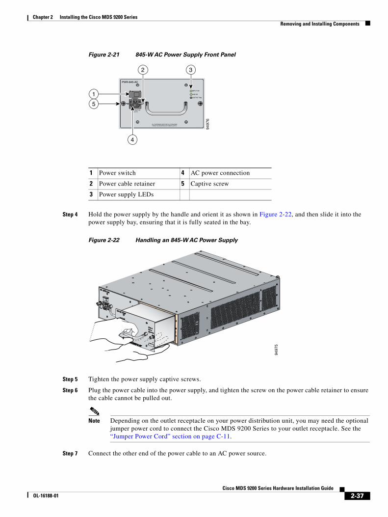
Chapter 2 Installing the Cisco MDS 9200 Series Removing and Installing Components
Figure 2-21 845-W AC Power Supply Front Panel
Step 4 Hold the power supply by the handle and orient it as shown in Figure 2-22, and then slide it into the power supply bay, ensuring that it is fully seated in the bay.
Figure 2-22 Handling an 845-W AC Power Supply
Step 5 Tighten the power supply captive screws.
Step 6 Plug the power cable into the power supply, and tighten the screw on the power cable retainer to ensure the cable cannot be pulled out.
Note Depending on the outlet receptacle on your power distribution unit, you may need the optional jumper power cord to connect the Cisco MDS 9200 Series to your outlet receptacle. See the “Jumper Power Cord” section on page C-11.
Step 7 Connect the other end of the power cable to an AC power source.
1 Power switch 4 AC power connection
2 Power cable retainer 5 Captive screw
3 Power supply LEDs
9497
6
PWR-845-AC
100-240V 12-5A50/60 Hz
INPUT OK
FAN OK
OUTPUT FAIL
ALL FASTENERS MUST BE FULLY ENGAGEDPRIOR TO OPERATING OF POWER SUPPLY
5
1
2 3
4
9497
5
2-37Cisco MDS 9200 Series Hardware Installation Guide
OL-16188-01
Chapter 2 Installing the Cisco MDS 9200 Series Removing and Installing Components
Caution In a system with dual power supplies, connect each power supply to a separate power source. In case of a power source failure, the second source will most likely still be available.
Step 8 Turn the power switch to the on (|) position on the power supply.
Step 9 Verify power supply operation by checking that the power supply LEDs are in the following states:
• Input Ok LED is green.
• Fan Ok LED is green.
• Output Fail LED is off.
Removing and Installing the Fan ModuleThe fan module is designed to be removed and replaced while the system is operating without presenting an electrical hazard or damage to the system, provided the replacement is performed promptly.
This section includes the following topics:
• Removing a Fan Module, page 2-39
• Installing a Fan Module, page 2-39
You will need a flat-blade or number 2 Phillips screwdriver to perform these procedures.
Caution The Cisco MDS 9000 Family switches have internal temperature sensors that are capable of shutting down the system if the temperature at different points within the chassis exceed certain safety thresholds. To be effective, the temperature sensors require the presence of airflow; therefore, in the event a fan module is removed from the chassis, the Cisco MDS 9000 Family switches will be shut down after five minutes to prevent potentially undetectable overheating. However, the switches will shut down sooner if the higher-level temperature threshold is exceeded.
2-38Cisco MDS 9200 Series Hardware Installation Guide
OL-16188-01

Chapter 2 Installing the Cisco MDS 9200 Series Removing and Installing Components
Figure 2-23 shows a fan module partially installed in the Cisco MDS 9200 Series.
Figure 2-23 Fan Module
Removing a Fan Module
Warning When removing the fan tray, keep your hands and fingers away from the spinning fan blades. Let the fan blades completely stop before you remove the fan tray. Statement 258
To remove a fan module, follow these steps:
Step 1 Loosen the two captive screws on the fan module by turning them counterclockwise, using a flat-blade or number 2 Phillips screwdriver if required.
Step 2 Grasp the fan module with both hands and pull it outward; rock it gently, if necessary, to unseat the power connector from the backplane.
Step 3 Pull the fan module clear of the chassis.
Caution If the switch is powered on, you must hot-swap another fan module into this switch within five minutes.
Installing a Fan Module
To install a fan module, follow these steps:
Step 1 Hold the fan module with the Fan Status LED at the top (see Figure 2-23).
Step 2 Place the fan module into the front chassis cavity so it rests on the chassis, lift the fan module up slightly to align the top and bottom chassis guides, then push the fan module into the chassis until it seats in the backplane and the captive screws make contact with the chassis, and tighten the captive screws.
LINK-
GE1GE2
1 2 3 4
LINK-10 11 12 13 14
5 6 7 8 9
1 2 3 45 6 7 8
9 10 11 1213 14 15 16
1220
02
MDS 9216i
2-39Cisco MDS 9200 Series Hardware Installation Guide
OL-16188-01

Chapter 2 Installing the Cisco MDS 9200 Series Removing and Installing Components
Step 3 Listen for the fans if the switch is powered on. You should immediately hear them operating. If you do not hear them, ensure that the fan module is inserted completely in the chassis and the faceplate is flush with the outside surface of the chassis.
Step 4 Verify that the Fan Status LED is green. If the LED is not green, one or more fans are faulty. If this occurs, contact your customer service representative for a replacement part.
Note If you purchased this product through a Cisco reseller, contact the reseller directly for technical support. If you purchased this product directly from Cisco, contact Cisco Technical Support at this URL: http://www.cisco.com/warp/public/687/Directory/DirTAC.shtml.
Removing the Cisco MDS 9200 SeriesWhen removing the Cisco MDS 9200 Series from the rack, remove the slider brackets first, and then the front screws fastening the front rack-mount brackets to the rack.
Note The slider rail and C brackets do not have a stop mechanism when sliding in and out. If the front of the chassis is unfastened from the rack and the chassis slides forward on the slider rails, it may slip off the end of the rails and fall out of the rack.
To remove the Cisco MDS 9200 Series from the rack, follow these steps:
Step 1 Remove the screws fastening the slider bracket to the mounting rails.
Step 2 Slide the slider brackets out of the C brackets on the sides of the Cisco MDS 9200 Series.
Step 3 Ensure the weight of the Cisco MDS 9200 Series is supported; for example, being held by another person.
Step 4 Remove the screws fastening the front rack-mount brackets on the Cisco MDS 9200 Series to the mounting rails, and remove the Cisco MDS 9200 Series from the rack.
2-40Cisco MDS 9200 Series Hardware Installation Guide
OL-16188-01

Send documenta t ion comments to mds feedba ck -doc@c i sco .com
COL-16188-01
C H A P T E R 3
Connecting the Cisco MDS 9200 SeriesThe Cisco MDS 9200 Series provides the following types of ports:
• Console port (interface module)—An RS-232 port that you can use to create a local management connection.
• COM1 port (interface module)—An RS-232 port that you can use to connect to an external serial communication device such as a modem.
• MGMT 10/100 Ethernet port (interface module)—An Ethernet port that you can use to access and manage the switch by IP address, such as through the CLI or Cisco Fabric Manager.
• Fibre Channel ports (supervisor and switching modules)—Fibre Channel ports that you can use to connect to the SAN, or for in-band management.
• Other port types provided by the optional module, if installed, such as the iSCSI and/or FCIP over Gigabit Ethernet ports on the 4-port or 8-port IPS modules.
Caution When running power and data cables in overhead or subfloor cable trays, Cisco strongly recommends that power cables and other potential noise sources must be located as far away as practical from network cabling that terminates on Cisco equipment. In situations where long parallel cable runs cannot be separated by at least 3.3 ft (1 m), Cisco recommends shielding any potential noise sources by housing them in a grounded metallic conduit.
This chapter includes the following topics:
• Preparing for Network Connections, page 3-2
• Connecting to the Console Port, page 3-2
• Connecting to the COM1 Port, page 3-4
• Connecting to the MGMT 10/100 Ethernet Port, page 3-5
• Connecting to a Fibre Channel Port, page 3-6
3-1isco MDS 9200 Series Hardware Installation Guide

Chapter 3 Connecting the Cisco MDS 9200 Series Preparing for Network Connections
Preparing for Network ConnectionsWhen preparing your site for network connections to the Cisco MDS 9200 Series, consider the following for each type of interface, and gather all the required equipment before connecting the ports:
• Cabling required for each interface type
• Distance limitations for each signal type
• Additional interface equipment required
Connecting to the Console PortThe console port (labeled Console) is an RS-232 port with an RJ-45 interface. (See Figure 3-1.) The console port is an asynchronous (async) serial port; any device connected to this port must be capable of asynchronous transmission.
Cisco recommends using this port to create a local management connection to set the IP address and other initial configuration settings before connecting the switch to the network for the first time.
Caution The console port can be used to connect to a modem, however, Cisco recommends using the COM1 port for this purpose. If you decide to connect the console port to a modem, do not connect it while the switch is booting; connect either before powering the switch on or after the switch has completed the boot process.
Figure 3-1 Connecting to the Console Port on the Cisco MDS 9200 Series
You can use the console port to perform the following:
• Configure the Cisco MDS 9200 Series from the CLI.
• Monitor network statistics and errors.
• Configure SNMP agent parameters.
• Download software updates.
FANSTATUS
FAN-MOD-2
1
2
1220
04
1 2 3 4 5 6 7 8 9 10 11 12 13 14 15 16
STAT
US
SYST
EM
RES
ET CONSOLE MGMT 10/100
MDS 9216iCOM1
—SPEED LINK—
LINK-
—SPEEDLINK—
STATUS
1 5 6 7 8 9
LINK— —SPEED
10 11 12 13 142 3 4
GE1
LINK-
GE2
Console
3-2Cisco MDS 9200 Series Hardware Installation Guide
OL-16188-01

Chapter 3 Connecting the Cisco MDS 9200 Series Connecting to the Console Port
Note To connect the console port to a computer terminal, the computer must support VT100 terminal emulation. The terminal emulation software—frequently an application such as HyperTerminal or Procomm Plus—makes communication between the Cisco MDS 9200 Series and a computer possible during setup and configuration.
To connect the console port to a computer terminal, follow these steps:
Step 1 Configure the terminal emulator program to match the following default port characteristics: 9600 baud, 8 data bits, 1 stop bit, no parity.
Step 2 Connect the supplied RJ-45 to DB-9 female adapter or RJ-45 to DB-25 female adapter (depending on your computer serial port) to the computer serial port. Cisco recommends using the adapter and cable provided with the switch.
Step 3 Connect the console cable (a rollover RJ-45 to RJ-45 cable) to the console port (see Figure 3-1) and to the RJ-45 to DB-9 adapter or RJ-45 to DB-25 adapter at the computer serial port.
Note For configuration instructions, see the Cisco MDS 9000 Family CLI Configuration Guide or the Cisco MDS 9000 Family Fabric Manager Configuration Guide.
3-3Cisco MDS 9200 Series Hardware Installation Guide
OL-16188-01
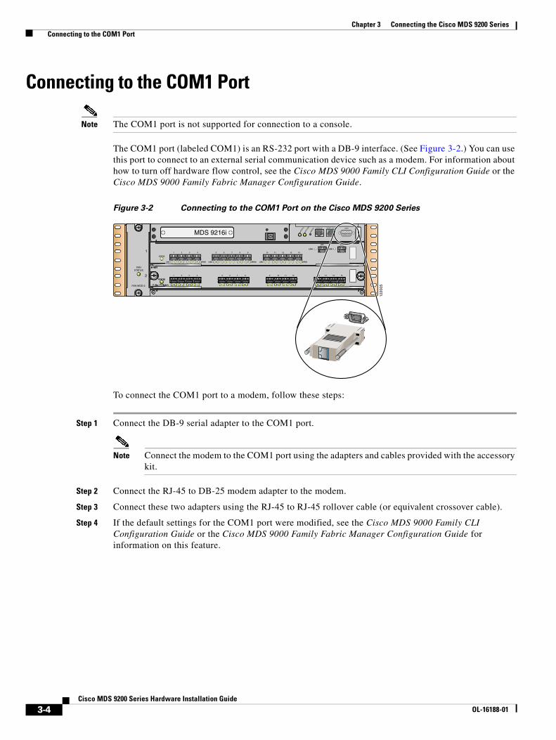
Chapter 3 Connecting the Cisco MDS 9200 Series Connecting to the COM1 Port
Connecting to the COM1 Port
Note The COM1 port is not supported for connection to a console.
The COM1 port (labeled COM1) is an RS-232 port with a DB-9 interface. (See Figure 3-2.) You can use this port to connect to an external serial communication device such as a modem. For information about how to turn off hardware flow control, see the Cisco MDS 9000 Family CLI Configuration Guide or the Cisco MDS 9000 Family Fabric Manager Configuration Guide.
Figure 3-2 Connecting to the COM1 Port on the Cisco MDS 9200 Series
To connect the COM1 port to a modem, follow these steps:
Step 1 Connect the DB-9 serial adapter to the COM1 port.
Note Connect the modem to the COM1 port using the adapters and cables provided with the accessory kit.
Step 2 Connect the RJ-45 to DB-25 modem adapter to the modem.
Step 3 Connect these two adapters using the RJ-45 to RJ-45 rollover cable (or equivalent crossover cable).
Step 4 If the default settings for the COM1 port were modified, see the Cisco MDS 9000 Family CLI Configuration Guide or the Cisco MDS 9000 Family Fabric Manager Configuration Guide for information on this feature.
FANSTATUS
FAN-MOD-2
1
2
1220
05
1 2 3 4 5 6 7 8 9 10 11 12 13 14 15 16
STAT
US
SYST
EM
RES
ET CONSOLE MGMT 10/100
MDS 9216iCOM1
—SPEED LINK—
LINK-
—SPEEDLINK—
STATUS
1 5 6 7 8 9
LINK— —SPEED
10 11 12 13 142 3 4
GE1
LINK-
GE2
3-4Cisco MDS 9200 Series Hardware Installation Guide
OL-16188-01

Chapter 3 Connecting the Cisco MDS 9200 Series Connecting to the MGMT 10/100 Ethernet Port
The default COM1 settings are as follows:
line Aux: Speed: 9600 bauds Databits: 8 bits per byte Stopbits: 1 bit(s) Parity: none Modem In: Enable Modem Init-String - default : ATE0Q1&D2&C1S0=1\015 Statistics: tx:17 rx:0 Register Bits:RTS|DTR
Connecting to the MGMT 10/100 Ethernet Port
Caution To prevent an IP address conflict, do not connect the MGMT 10/100 Ethernet port to the network until the initial configuration is complete. For configuration instructions, see the Cisco MDS 9000 Family CLI Configuration Guide or the Cisco MDS 9000 Family Fabric Manager Configuration Guide.
The MGMT 10/100 Ethernet port is autosensing and has an RJ-45 interface. (See Figure 3-3.) You can use this port to access and manage the switch by its IP address, such as through the Cisco Fabric Manager.
Figure 3-3 Connecting to the MGMT 10/100 Ethernet Port on the Cisco MDS 9200 Series
To connect the MGMT 10/100 Ethernet port to an external hub, switch, or router, follow these steps:
Step 1 Connect the appropriate modular cable to the MGMT 10/100 Ethernet port:
• Use modular, RJ-45, straight-through UTP cables to connect the 10/100 management port to an Ethernet switch port or hub.
• Use a cross-over cable to connect to a router interface.
Step 2 Connect the other end of the cable to the device.
FANSTATUS
FAN-MOD-2
1
2
1220
06
1 2 3 4 5 6 7 8 9 10 11 12 13 14 15 16
STAT
US
SYST
EM
RES
ET CONSOLE MGMT 10/100
MDS 9216iCOM1
—SPEED LINK—
LINK-
—SPEEDLINK—
STATUS
1 5 6 7 8 9
LINK— —SPEED
10 11 12 13 142 3 4
GE1
LINK-
GE2
MGMT 10/100
3-5Cisco MDS 9200 Series Hardware Installation Guide
OL-16188-01

Chapter 3 Connecting the Cisco MDS 9200 Series Connecting to a Fibre Channel Port
Connecting to a Fibre Channel PortThe Fibre Channel ports on the switch modules are compatible with LC-type fiber-optic SFP transceivers and cables. You can use the Fibre Channel ports to connect to the SAN or for in-band management. For information about configuring the switch for in-band management, see the Cisco MDS 9000 Family CLI Configuration Guide or the Cisco MDS 9000 Family Fabric Manager Configuration Guide.
The Cisco MDS 9000 Family supports both Fibre Channel and Gigabit Ethernet protocols for SFP transceivers. Each transceiver must match the transceiver on the other end of the cable, and the cable must not exceed the stipulated cable length for reliable communications. SFP transceivers can be ordered separately or with the Cisco MDS 9200 Series.
Warning Class 1 laser product. Statement 1008
Warning Invisible laser radiation may be emitted from disconnected fibers or connectors. Do not stare into beams or view directly with optical instruments. Statement 1051
Caution Wear an ESD wrist strap connected to the chassis when handling transceivers. Keep optical connectors covered when not in use, and do not touch connector ends. The fiber-optic connectors must be free of dust, oil, and other contaminants.
This section includes the following topics:
• Removing and Installing X2 Transceivers, page 3-6
• Removing and Installing SFP Transceivers, page 3-8
• Removing and Installing Cables into SFP Transceivers, page 3-11
• Maintaining SFP Transceivers and Fiber-Optic Cables, page 3-13
Removing and Installing X2 Transceivers
Caution Excessively removing and installing an X2 transceiver can shorten its life. Do not remove and insert X2 transceivers more often unless it is absolutely necessary. Cisco recommends disconnecting cables before installing or removing SFP transceivers to prevent damage to the cable or transceiver.
Note Use only Cisco X2 transceivers listed in Table B-10 on page B-7 on the Cisco MDS 9200 Series. Each X2 transceiver is encoded with model information that enables the switch to verify that the X2 transceiver meets the requirements for the switch. For instructions specific to the transceiver type, see the “X2 Transceiver Specifications” section on page B-6.
3-6Cisco MDS 9200 Series Hardware Installation Guide
OL-16188-01
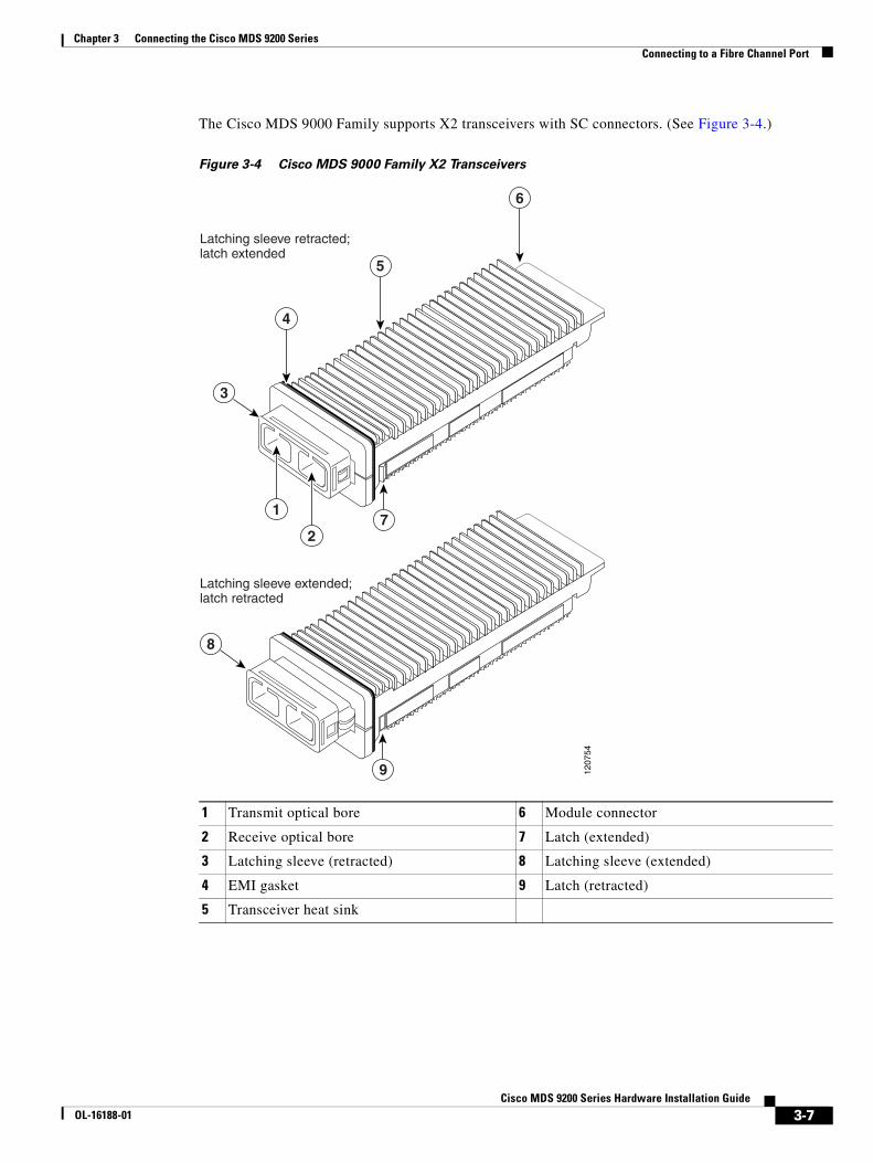
Chapter 3 Connecting the Cisco MDS 9200 Series Connecting to a Fibre Channel Port
The Cisco MDS 9000 Family supports X2 transceivers with SC connectors. (See Figure 3-4.)
Figure 3-4 Cisco MDS 9000 Family X2 Transceivers
1 Transmit optical bore 6 Module connector
2 Receive optical bore 7 Latch (extended)
3 Latching sleeve (retracted) 8 Latching sleeve (extended)
4 EMI gasket 9 Latch (retracted)
5 Transceiver heat sink
5
6
1207
54
4
3
8
1
27
9
Latching sleeve retracted;latch extended
Latching sleeve extended;latch retracted
3-7Cisco MDS 9200 Series Hardware Installation Guide
OL-16188-01
Chapter 3 Connecting the Cisco MDS 9200 Series Connecting to a Fibre Channel Port
Installing an X2 Transceiver
To install an X2 transceiver, follow these steps:
Step 1 Attach an ESD-preventive wrist strap and follow its instructions for use.
Caution If the transceiver does not install easily, ensure that it is correctly oriented before continuing.
Step 2 Remove the dust cover from the port end of the transceiver.
Step 3 Insert the transceiver into the port. ensure the transceiver is fully seated.
Note If you cannot install the cable into the transceiver, insert or leave the dust plug in the cable end of the transceiver.
Removing an X2 Transceiver
To remove an X2 transceiver, follow these steps:
Step 1 Attach an ESD-preventive wrist strap and follow its instructions for use.
Step 2 If a cable is installed in the transceiver:
a. Record the cable and port connections for later reference.
b. Press the release latch on the cable, grasp the connector near the connection point, and gently pull the connector from the transceiver.
c. Insert a dust plug into the cable end of the transceiver.
Caution If the transceiver does not remove easily in the next step, push the transceiver completely in and then ensure that the latch is in the correct position before continuing.
Step 3 Remove the transceiver from the port.
Step 4 Insert a dust cover into the port end of the transceiver and place the transceiver on an antistatic mat or into a static shielding bag if you plan to return it to the factory.
Removing and Installing SFP Transceivers
Caution Excessively removing and installing an SFP transceiver can shorten its life. Do not remove and insert SFP transceivers more often unless it is absolutely necessary. Cisco recommends disconnecting cables before installing or removing SFP transceivers to prevent damage to the cable or transceiver.
3-8Cisco MDS 9200 Series Hardware Installation Guide
OL-16188-01
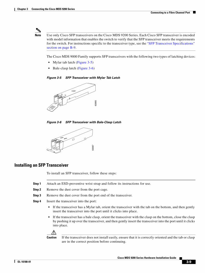
Chapter 3 Connecting the Cisco MDS 9200 Series Connecting to a Fibre Channel Port
Note Use only Cisco SFP transceivers on the Cisco MDS 9200 Series. Each Cisco SFP transceiver is encoded with model information that enables the switch to verify that the SFP transceiver meets the requirements for the switch. For instructions specific to the transceiver type, see the “SFP Transceiver Specifications” section on page B-9.
The Cisco MDS 9000 Family supports SFP transceivers with the following two types of latching devices:
• Mylar tab latch (Figure 3-5)
• Bale-clasp latch (Figure 3-6)
Figure 3-5 SFP Transceiver with Mylar Tab Latch
Figure 3-6 SFP Transceiver with Bale-Clasp Latch
Installing an SFP Transceiver
To install an SFP transceiver, follow these steps:
Step 1 Attach an ESD-preventive wrist strap and follow its instructions for use.
Step 2 Remove the dust cover from the port cage.
Step 3 Remove the dust cover from the port end of the transceiver.
Step 4 Insert the transceiver into the port:
• If the transceiver has a Mylar tab, orient the transceiver with the tab on the bottom, and then gently insert the transceiver into the port until it clicks into place.
• If the transceiver has a bale clasp, orient the transceiver with the clasp on the bottom, close the clasp by pushing it up over the transceiver, and then gently insert the transceiver into the port until it clicks into place.
Caution If the transceiver does not install easily, ensure that it is correctly oriented and the tab or clasp are in the correct position before continuing.
6306
563
067
3-9Cisco MDS 9200 Series Hardware Installation Guide
OL-16188-01
Chapter 3 Connecting the Cisco MDS 9200 Series Connecting to a Fibre Channel Port
Note If you cannot install the cable into the transceiver, insert or leave the dust plug in the cable end of the transceiver.
Removing an SFP Transceiver
To remove an SFP transceiver, follow these steps:
Step 1 Attach an ESD-preventive wrist strap and follow its instructions for use.
Step 2 If a cable is installed in the transceiver:
a. Record the cable and port connections for later reference.
b. Press the release latch on the cable, grasp the connector near the connection point, and gently pull the connector from the transceiver.
c. Insert a dust plug into the cable end of the transceiver.
Caution If the transceiver does not remove easily in the next step, push the transceiver completely in and then ensure that the latch is in the correct position before continuing.
Step 3 Remove the transceiver from the port:
• If the transceiver has a Mylar tab latch, gently pull the tab straight out (do not twist), and then pull the transceiver out of the port.
• If the transceiver has a bale clasp latch, open the clasp by pressing it downwards, and then pull the transceiver out of the port.
Note If you have difficulty removing a bale clasp SFP transceiver, you should reseat the SFP by returning the bale clasp in the up position. Then press the SFP inward and upward into the cage. Next, lower the bale clasp and pull the SFP straight out with a slight upward lifting force (see Figure 3-7). Be careful not to damage the port cage during this process.
3-10Cisco MDS 9200 Series Hardware Installation Guide
OL-16188-01
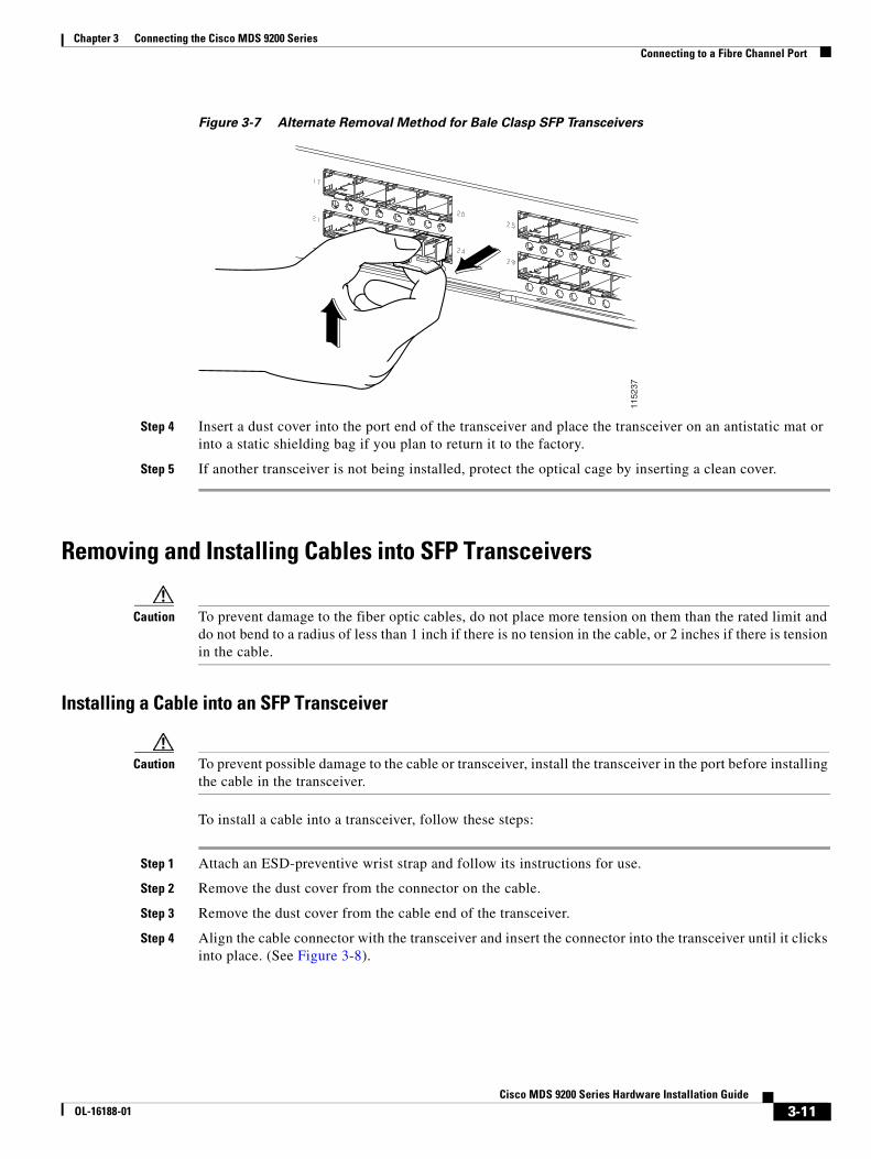
Chapter 3 Connecting the Cisco MDS 9200 Series Connecting to a Fibre Channel Port
Figure 3-7 Alternate Removal Method for Bale Clasp SFP Transceivers
Step 4 Insert a dust cover into the port end of the transceiver and place the transceiver on an antistatic mat or into a static shielding bag if you plan to return it to the factory.
Step 5 If another transceiver is not being installed, protect the optical cage by inserting a clean cover.
Removing and Installing Cables into SFP Transceivers
Caution To prevent damage to the fiber optic cables, do not place more tension on them than the rated limit and do not bend to a radius of less than 1 inch if there is no tension in the cable, or 2 inches if there is tension in the cable.
Installing a Cable into an SFP Transceiver
Caution To prevent possible damage to the cable or transceiver, install the transceiver in the port before installing the cable in the transceiver.
To install a cable into a transceiver, follow these steps:
Step 1 Attach an ESD-preventive wrist strap and follow its instructions for use.
Step 2 Remove the dust cover from the connector on the cable.
Step 3 Remove the dust cover from the cable end of the transceiver.
Step 4 Align the cable connector with the transceiver and insert the connector into the transceiver until it clicks into place. (See Figure 3-8).
1152
37
3-11Cisco MDS 9200 Series Hardware Installation Guide
OL-16188-01
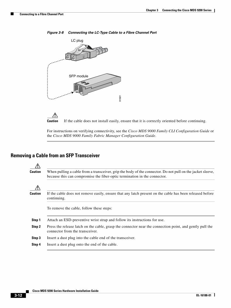
Chapter 3 Connecting the Cisco MDS 9200 Series Connecting to a Fibre Channel Port
Figure 3-8 Connecting the LC-Type Cable to a Fibre Channel Port
Caution If the cable does not install easily, ensure that it is correctly oriented before continuing.
For instructions on verifying connectivity, see the Cisco MDS 9000 Family CLI Configuration Guide or the Cisco MDS 9000 Family Fabric Manager Configuration Guide.
Removing a Cable from an SFP Transceiver
Caution When pulling a cable from a transceiver, grip the body of the connector. Do not pull on the jacket sleeve, because this can compromise the fiber-optic termination in the connector.
Caution If the cable does not remove easily, ensure that any latch present on the cable has been released before continuing.
To remove the cable, follow these steps:
Step 1 Attach an ESD-preventive wrist strap and follow its instructions for use.
Step 2 Press the release latch on the cable, grasp the connector near the connection point, and gently pull the connector from the transceiver.
Step 3 Insert a dust plug into the cable end of the transceiver.
Step 4 Insert a dust plug onto the end of the cable.
LC plug
SFP module
9168
1
3-12Cisco MDS 9200 Series Hardware Installation Guide
OL-16188-01

Chapter 3 Connecting the Cisco MDS 9200 Series Connecting to a Fibre Channel Port
Maintaining SFP Transceivers and Fiber-Optic CablesSFP transceivers and fiber-optic cables must be kept clean and dust-free to maintain high signal accuracy and prevent damage to the connectors. Attenuation (Loss of Light) is increased by contamination and should be below 0.35 dB.
Consider the following maintenance guidelines:
• SFP transceivers are static sensitive. To prevent ESD damage, wear an ESD-preventive wrist strap that is connected to the chassis.
• Do not remove and insert a transceiver more often than is necessary. Repeated removals and insertions can shorten its useful life.
• Keep all optical connections covered when not in use. If they become dusty, clean before using to prevent dust from scratching the fiber-optic cable ends.
• Do not touch ends of connectors to prevent fingerprints and other contamination.
• Clean regularly; the required frequency of cleaning depends upon the environment. In addition, clean connectors if they are exposed to dust or accidentally touched. Both wet and dry cleaning techniques can be effective; refer to your site’s fiber-optic connection cleaning procedure.
• Inspect routinely for dust and damage. If damage is suspected, clean and then inspect fiber ends under a microscope to determine if damage has occurred.
3-13Cisco MDS 9200 Series Hardware Installation Guide
OL-16188-01

Chapter 3 Connecting the Cisco MDS 9200 Series Connecting to a Fibre Channel Port
3-14Cisco MDS 9200 Series Hardware Installation Guide
OL-16188-01

Send documenta t ion comments to mds feedba ck -doc@c i sco .com
Cisco MOL-16188-01
A
P P E N D I X A Cabinet and Rack InstallationThis appendix provides information on how to install cabinet and rack, and includes the following sections:
• Cabinet and Rack Requirements, page A-1
• Cisco MDS 9000 Family telco and EIA Shelf Bracket, page A-4
Cabinet and Rack RequirementsThis section provides the Cisco MDS 9000 Family requirements for the following types of cabinets and racks, assuming an external ambient air temperature range of 0 to 104oF (0 to 40oC):
• Standard perforated cabinets
• Solid-walled cabinets with a roof fan tray (bottom to top cooling)
• Standard open racks
• telco racks
Note If you are selecting an enclosed cabinet, Cisco recommends one of the thermally validated types: standard perforated or solid-walled with a fan tray.
Note Do not use racks that have obstructions (such as power strips), because the obstructions could impair access to field-replaceable units (FRUs).
General Requirements for Cabinets and RacksThe cabinet or rack must be one of the following types:
• Standard 19-in. (48.3 cm) (four-post EIA cabinet or rack, with mounting rails that conform to English universal hole spacing per section 1 of ANSI/EIA-310-D-1992. See the “Requirements Specific to Perforated Cabinets” section on page A-2 and the “Requirements Specific to Solid-Walled Cabinets” section on page A-3.
• Standard two-post telco rack, with mounting rails that conform to English universal hole spacing per section 1 of ANSI/EIA-310-D-1992. See the “Requirements Specific to telco Racks” section on page A-3.
A-1DS 9200 Series Hardware Installation Guide

Appendix A Cabinet and Rack Installation Cabinet and Rack Requirements
The cabinet or rack must also meet the following requirements:
• The minimum vertical rack space per chassis must be three RU (rack units), equal to 5.25 in. (13.3 cm).
• The width between the rack-mounting rails must be at least 17.75 in. (45.1 cm) if the rear of the switch is not attached to the rack. For four-post EIA racks, this is the distance between the two front rails.
• For four-post EIA cabinets (perforated or solid-walled):
– The minimum spacing for the bend radius for fiber-optic cables should have the front mounting rails of the cabinet offset from the front door by a minimum of 3 in. (7.6 cm), and a minimum of 5 in. (12.7 cm) if cable management brackets are installed on the front of the chassis.
– The distance between the outside face of the front mounting rail and the outside face of the back mounting rail should be 23.5 to 34.0 in. (59.7 to 86.4 cm) to allow for rear bracket installation.
– A minimum of 2.5 in. (6.4 cm) of clear space should exist between the side edge of the chassis and the side wall of the cabinet. No sizeable flow obstructions should be immediately in the way of chassis air intake or exhaust vents.
Note Optional jumper power cords are available for use in a cabinet. See the “Jumper Power Cord” section on page C-11.
Requirements Specific to Perforated CabinetsA perforated cabinet is defined here as a cabinet with perforated front and rear doors and solid side walls. In addition to the requirements listed in the “General Requirements for Cabinets and Racks” section on page A-1, perforated cabinets must meet the following requirements:
• The front and rear doors must have at least a 60% open area perforation pattern, with at least 15 square inches of open area per rack unit of door height.
• Cisco recommends that the roof be perforated with at least a 20 percent open area.
• Cisco recommends an open or perforated cabinet floor to enhance cooling.
A perforated cabinet that conforms to these requirements is available from Rittal Corporation:
Rittal Corporation
One Rittal Place
Springfield, OH 45504
Contact: (800) 477–4220
Cabinet P/N: Rittal 9969427
Cabinet description: PS-DK/OEM Cabinet Assembly, (78.7 in.) 1998 mm X 23.6 in. (600 mm) X 39.4 in. (1000 mm) (H x W x D) (42 RU)
A-2Cisco MDS 9200 Series Hardware Installation Guide
OL-16188-01
Appendix A Cabinet and Rack Installation Cabinet and Rack Requirements
Requirements Specific to Solid-Walled CabinetsA solid-walled cabinet is defined here as a cabinet with solid front and rear doors and solid side walls. In addition to the requirements listed in the “General Requirements for Cabinets and Racks” section on page A-1, solid-walled cabinets must meet the following requirements:
• A roof-mounted fan tray and an air cooling scheme in which the fan tray pulls air in at the bottom of the cabinet and exhausts it out the top, with a minimum of 500 cfm of airflow exiting the cabinet roof through the fan tray.
• Nonperforated (solid and sealed) front and back doors and side panels so that air travels predictably from bottom to top.
• A recommended cabinet depth of 36 to 42 in.(91.4 to 106.7 cm) to allow the doors to close and for adequate airflow.
• A minimum of 150 sq. in. (968 sq. cm) of open area at the floor air intake of the cabinet.
• The lowest piece of equipment should be installed a minimum of 1.75 in. (4.4 cm) above the floor openings to prevent blocking the floor intake.
Requirements Specific to Standard Open RacksIn addition to the requirements listed in the “General Requirements for Cabinets and Racks” section on page A-1, if mounting the chassis in an open rack (no side panels or doors), ensure that the rack meets the following requirements:
• The minimum width between two front mounting rails must be 17.75 in. (45.1 cm).
• The minimum vertical rack space per chassis must be three RU (rack unit), equal to 5.25 in. (13.3 cm).
• The distance between the outside face of the front mounting rail and the outside face of the back mounting rail should be 23.5 to 34.0 in. (59.7 to 86.4 cm) to allow for rear bracket installation.
• The horizontal distance between the chassis and any adjacent chassis should be 6 in.(15.2 cm), and the distance between the chassis air vents and any walls should be 2.5 in. (6.4 cm).
Requirements Specific to telco RacksIn addition to the requirements listed in the “General Requirements for Cabinets and Racks” section on page A-1, telco racks should meet the following requirements:
• The width of the rack between the two rack-mounting rails should be at least 17.75 in. (45.1 cm).
• The distance between the chassis air vents and any walls should be 2.5 in. (6.4 cm).
A-3Cisco MDS 9200 Series Hardware Installation Guide
OL-16188-01
Appendix A Cabinet and Rack Installation Cisco MDS 9000 Family telco and EIA Shelf Bracket
Cisco MDS 9000 Family telco and EIA Shelf BracketThe optional telco and EIA Shelf Bracket Kit (part number DS-SHELF=) can temporarily or permanently support the Cisco MDS 9200 Series during installation. Once the front rack-mount brackets are securely attached to the rack-mounting rails, the shelf bracket can be removed. This kit supports the following configurations:
• A Cisco MDS 9200 Series in a two-post telco rack
• A Cisco MDS 9200 Series in a four-post EIA rack
This section describes the procedure for installing a Cisco MDS 9000 Family switch in a rack or cabinet using the optional telco and EIA Shelf Bracket Kit. It includes the following topics:
• Rack-Mounting Guidelines, page A-4
• Before Installing the Shelf Brackets, page A-5
• Installing the Shelf Bracket Kit into a Two-Post telco Rack, page A-6
• Installing the Shelf Bracket Kit into a Four-Post EIA Rack, page A-7
• Installing the Switch on the Shelf Brackets, page A-8
• Removing the Shelf Bracket Kit (Optional), page A-9
Note This optional kit is not provided with the switch; to order the kit, contact your switch supplier.
Note For additional support after removing the shelf brackets, ensure that the C brackets on the Cisco MDS 9200 Series are attached to the rear rack-mounting rails.
Rack-Mounting Guidelines
Caution If the rack is on wheels, ensure that the brakes are engaged or the rack is otherwise stabilized.
Caution If installing this kit in an EIA rack, attach the switch to all four rack-mounting rails; the EIA rails might not be thick enough to prevent flexing of the shelf brackets if only two rails are used.
Before rack-mounting the chassis, ensure that the cabinet or rack meets the following requirements:
• The specifications listed in the “Cabinet and Rack Requirements” section on page A-1.
• The depth of the rack between the front and rear mounting rails is at least 18 in.(45.7 cm) but less than or equal to 30 in. (76.2 cm). This is specific to four-post EIA cabinets or racks.
• The airflow and cooling are adequate and there is sufficient clearance around the air vents on the switch, as described in Appendix B, “Technical Specifications.” This is particularly important to verify if you are installing the switch in an enclosed cabinet.
A-4Cisco MDS 9200 Series Hardware Installation Guide
OL-16188-01
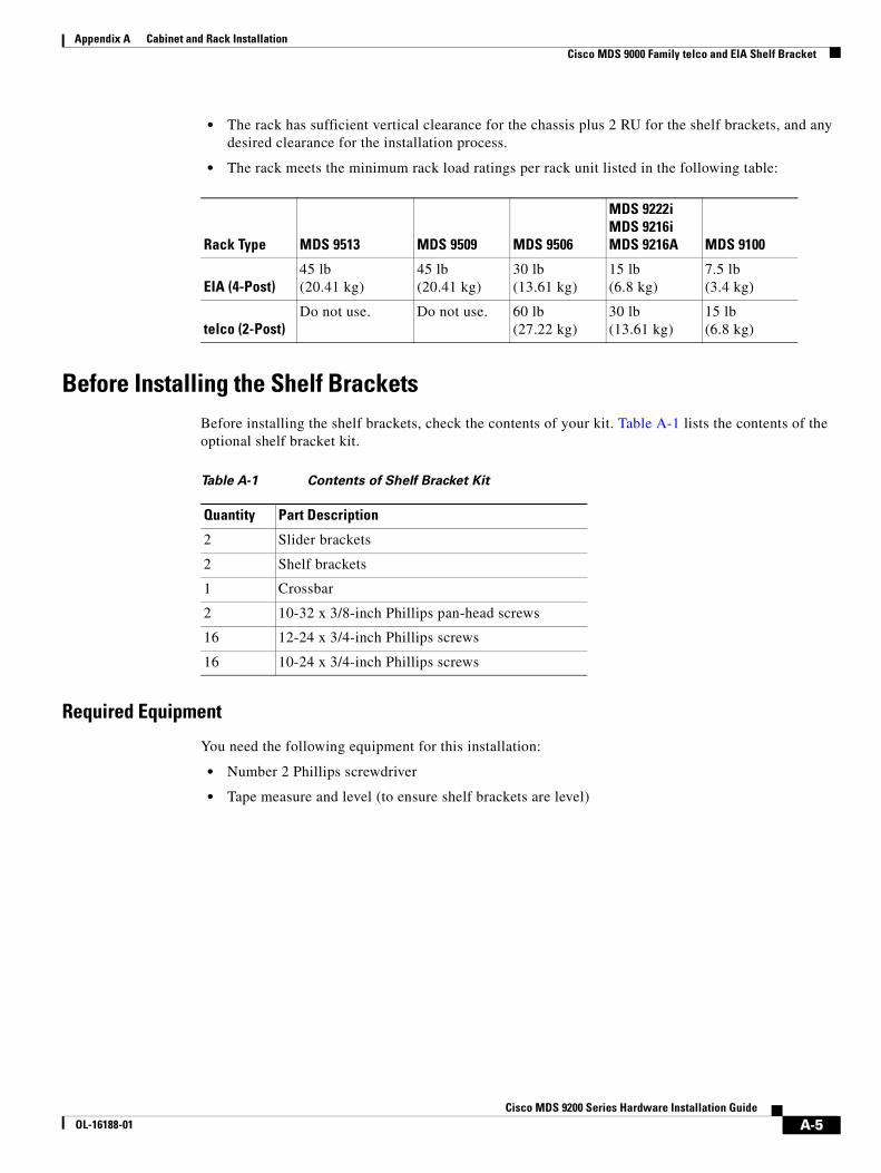
Appendix A Cabinet and Rack Installation Cisco MDS 9000 Family telco and EIA Shelf Bracket
• The rack has sufficient vertical clearance for the chassis plus 2 RU for the shelf brackets, and any desired clearance for the installation process.
• The rack meets the minimum rack load ratings per rack unit listed in the following table:
Before Installing the Shelf BracketsBefore installing the shelf brackets, check the contents of your kit. Table A-1 lists the contents of the optional shelf bracket kit.
Required Equipment
You need the following equipment for this installation:
• Number 2 Phillips screwdriver
• Tape measure and level (to ensure shelf brackets are level)
Rack Type MDS 9513 MDS 9509 MDS 9506
MDS 9222iMDS 9216iMDS 9216A MDS 9100
EIA (4-Post)45 lb (20.41 kg)
45 lb (20.41 kg)
30 lb (13.61 kg)
15 lb (6.8 kg)
7.5 lb (3.4 kg)
telco (2-Post)Do not use. Do not use. 60 lb
(27.22 kg)30 lb(13.61 kg)
15 lb(6.8 kg)
Table A-1 Contents of Shelf Bracket Kit
Quantity Part Description
2 Slider brackets
2 Shelf brackets
1 Crossbar
2 10-32 x 3/8-inch Phillips pan-head screws
16 12-24 x 3/4-inch Phillips screws
16 10-24 x 3/4-inch Phillips screws
A-5Cisco MDS 9200 Series Hardware Installation Guide
OL-16188-01

Appendix A Cabinet and Rack Installation Cisco MDS 9000 Family telco and EIA Shelf Bracket
Installing the Shelf Bracket Kit into a Two-Post telco RackFigure A-1 shows the installation of the shelf bracket kit into a two-post telco rack.
Figure A-1 Installing the Shelf Bracket Kit into a telco Rack
To install the shelf brackets in a telco rack, follow these steps:
Step 1 Position a shelf bracket inside a rack-mounting rail as shown in Figure A-1. Align the screw holes at the front of the shelf bracket with the holes in the rack-mounting rail. Then, attach the shelf bracket to the rack-mounting rail using a minimum of four 12-24 or 10-24 screws.
Note The bottom hole of the shelf bracket should align with the bottom hole of a rack unit on the rack-mounting rail (the hole immediately above the 1/2-in. spacing).
Step 2 Repeat with the other shelf bracket.
Step 3 Verify that the shelf brackets are at the same height (using the level or tape measure as desired).
Step 4 Attach the crossbar to the rear of the shelf brackets as shown in Figure A-1, using the 10-32 screws.
1 Rack-mounting rail (2x) 3 10-32 screws (2x)
2 Shelf bracket (2x) 4 Crossbar
12
3
4
1050
88
A-6Cisco MDS 9200 Series Hardware Installation Guide
OL-16188-01

Appendix A Cabinet and Rack Installation Cisco MDS 9000 Family telco and EIA Shelf Bracket
Installing the Shelf Bracket Kit into a Four-Post EIA RackFigure A-2 shows the installation of the shelf bracket kit into a four-post EIA rack.
Figure A-2 Installing the Shelf Bracket Kit into an EIA Rack
To install the shelf brackets in an EIA rack, follow these steps:
Step 1 Position a shelf bracket inside the rack-mounting rails as shown in Figure A-2. Align the screw holes at the front of the shelf bracket with the holes in the front rack-mounting rail. Then, attach the shelf bracket to the front rack-mounting rail using a minimum of four 12-24 or 10-24 screws.
Note The bottom hole of the shelf bracket should align with the bottom hole of a rack unit on the rack-mounting rail (the hole immediately above the 1/2-in. spacing).
Step 2 Repeat with the other shelf bracket.
Step 3 Verify that the shelf brackets are at the same height (using the level or tape measure as desired).
1 Rack-mounting rail (4x) 4 Crossbar
2 Shelf bracket (2x) 5 10-32 screws (2x)
3 Slider rail (2)
1
2
3
5
4
1050
87
A-7Cisco MDS 9200 Series Hardware Installation Guide
OL-16188-01
Appendix A Cabinet and Rack Installation Cisco MDS 9000 Family telco and EIA Shelf Bracket
Step 4 Attach the crossbar to the shelf brackets as shown in Figure A-2, using the 10-32 screws.
Step 5 Insert the slider rails into the shelf brackets as shown in Figure A-2. Then, attach them to the rear rack-mounting rails using a minimum of four 12-24 or 10-24 screws.
Installing the Switch on the Shelf BracketsThis section provides general instructions for installing the switch on top of the shelf brackets. For installation instructions, see the “Installing the Chassis in a Cabinet or Rack” section on page 2-5.
Warning This unit is intended for installation in restricted access areas. A restricted access area can be accessed only through the use of a special tool, lock and key, or other means of security. Statement 1017
Warning Only trained and qualified personnel should be allowed to install, replace, or service this equipment.Statement 1030
Note Before you install, operate, or service the system, refer to the Regulatory Compliance and Safety Information for the Cisco MDS 9000 Family for important safety information.
To install the switch on top of the shelf brackets, follow these steps:
Step 1 Ensure that the shelf brackets are level and securely attached to the rack-mounting rails, the crossbar is securely attached to the shelf brackets, and the rack is stabilized.
Step 2 Slide the switch onto the shelf brackets, ensuring it is squarely positioned.
Step 3 Attach the switch to the rack-mounting rails. See the “Installing the Chassis in a Cabinet or Rack” section on page 2-5.
Caution We recommend grounding the chassis, even if the rack is already grounded. There is a grounding pad with two threaded M4 holes on the chassis for attaching a grounding lug.
A-8Cisco MDS 9200 Series Hardware Installation Guide
OL-16188-01

Appendix A Cabinet and Rack Installation Cisco MDS 9000 Family telco and EIA Shelf Bracket
Removing the Shelf Bracket Kit (Optional)The shelf bracket kit can be removed once the Cisco MDS 9200 Series has been installed in a two-post telco or four-post EIA rack, and the front rack-mount brackets are securely attached to the rack-mounting rails. For additional support in an EIA rack, ensure that the C brackets on the Cisco MDS 9200 Series are attached to the rear rack-mounting rails.
To remove the shelf bracket kit, follow these steps:
Step 1 Remove the screws fastening the slider brackets to the rear rack-mounting rails. Then, slide the slider brackets out of the shelf brackets.
Step 2 Remove the screws fastening the crossbar to the shelf brackets and remove the crossbar.
Step 3 Remove the screws fastening the shelf brackets to the front rack-mounting rails. Then, remove the shelf brackets from the rack.
A-9Cisco MDS 9200 Series Hardware Installation Guide
OL-16188-01

Appendix A Cabinet and Rack Installation Cisco MDS 9000 Family telco and EIA Shelf Bracket
A-10Cisco MDS 9200 Series Hardware Installation Guide
OL-16188-01
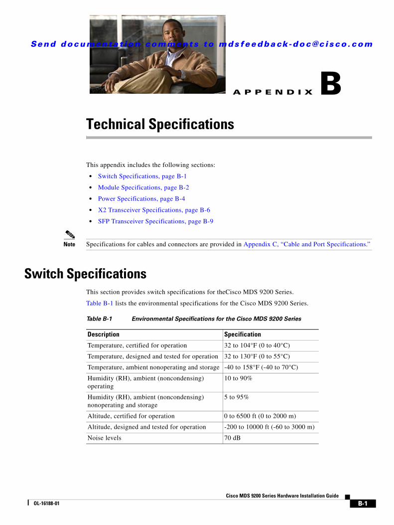
Send documenta t ion comments to mds feedba ck -doc@c i sco .com
Cisco MOL-16188-01
A
P P E N D I X B Technical SpecificationsThis appendix includes the following sections:
• Switch Specifications, page B-1
• Module Specifications, page B-2
• Power Specifications, page B-4
• X2 Transceiver Specifications, page B-6
• SFP Transceiver Specifications, page B-9
Note Specifications for cables and connectors are provided in Appendix C, “Cable and Port Specifications.”
Switch SpecificationsThis section provides switch specifications for theCisco MDS 9200 Series.
Table B-1 lists the environmental specifications for the Cisco MDS 9200 Series.
Table B-1 Environmental Specifications for the Cisco MDS 9200 Series
Description Specification
Temperature, certified for operation 32 to 104°F (0 to 40°C)
Temperature, designed and tested for operation 32 to 130°F (0 to 55°C)
Temperature, ambient nonoperating and storage -40 to 158°F (-40 to 70°C)
Humidity (RH), ambient (noncondensing) operating
10 to 90%
Humidity (RH), ambient (noncondensing) nonoperating and storage
5 to 95%
Altitude, certified for operation 0 to 6500 ft (0 to 2000 m)
Altitude, designed and tested for operation -200 to 10000 ft (-60 to 3000 m)
Noise levels 70 dB
B-1DS 9200 Series Hardware Installation Guide
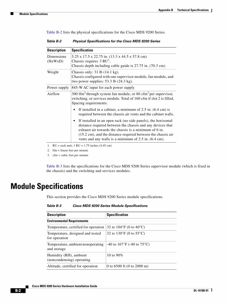
Appendix B Technical Specifications Module Specifications
Table B-2 lists the physical specifications for the Cisco MDS 9200 Series.
Table B-3 lists the specifications for the Cisco MDS 9200 Series supervisor module (which is fixed in the chassis) and the switching and services modules.
Module SpecificationsThis section provides the Cisco MDS 9200 Series module specifications.
Table B-2 Physical Specifications for the Cisco MDS 9200 Series
Description Specification
Dimensions (HxWxD)
5.25 x 17.5 x 22.75 in. (13.3 x 44.5 x 57.8 cm)Chassis requires 3 RU1. Chassis depth including cable guide is 27.75 in. (70.3 cm).
1. RU = rack unit; 1 RU = 1.75 inches (4.45 cm)
Weight Chassis only: 31 lb (14.1 kg). Chassis configured with one supervisor module, fan module, and two power supplies: 53.3 lb (24.3 kg).
Power supply 845-W AC input for each power supply
Airflow 300 lfm2 through system fan module, or 80 cfm3 per supervisor, switching, or services module. Total of 160 cfm if slot 2 is filled.Spacing requirements:
• If installed in a cabinet, a minimum of 2.5 in. (6.4 cm) is required between the chassis air vents and the cabinet walls.
• If installed in an open rack (no side panels), the horizontal distance required between the chassis and any devices that exhaust air towards the chassis is a minimum of 6 in. (15.2 cm), and the distance required between the chassis air vents and any walls is a minimum of 2.5 in. (6.4 cm).
2. lfm = linear feet per minute
3. cfm = cubic feet per minute
Table B-3 Cisco MDS 9200 Series Module Specifications
Description Specification
Environmental Requirements
Temperature, certified for operation 32 to 104°F (0 to 40°C)
Temperature, designed and tested for operation
32 to 130°F (0 to 55°C)
Temperature, ambient nonoperating and storage
-40 to 167°F (-40 to 75°C)
Humidity (RH), ambient (noncondensing) operating
10 to 90%
Altitude, certified for operation 0 to 6500 ft (0 to 2000 m)
B-2Cisco MDS 9200 Series Hardware Installation Guide
OL-16188-01

Appendix B Technical Specifications Module Specifications
Table B-4 lists the specifications for the batteries on the Cisco MDS 9000 Family Caching Services Module.
Weight of ModulesTable B-5 lists the weight for each module in the Cisco MDS 9000 Family.
Altitude, designed and tested for operation
-200 to 10000 ft (-60 to 3000 m)
Physical Characteristics
Dimensions 1.75 x15.5 x16.5 in. (4.4 x 39.4 x 41.9 cm)
Note These are the maximum dimensions of faceplate and board, and include connectors on board.
Weight 8 to 11.5 lb (1.4 to 5.2 kg)
Table B-3 Cisco MDS 9200 Series Module Specifications (continued)
Description Specification
Table B-4 Caching Services Module Battery Specifications
Description Specification
Nominal voltage 9.6 V
Rated capacity Typical discharge capacity at 0.2C rate: 2100 mAh
Minimum discharge capacity at 0.2C rate: 2000 mAh
Minimum discharge capacity at 5C rate: 1800 mAh
(1V/cell discharge cut-off)
Discharge The battery is capable of continuous discharge from (41 to 140°F (5 to +60°C)at 5C-rate
Charge From 32 to 59°F (0 to 15°C) at C/10 rate and from 59 to 104°F (15 to 40°C) at C/2-rate
Storage temperature 32 to 95°F (0 to 35°C)
Relative humidity range From 5 to 90%
Table B-5 Weight of Modules in the Cisco MDS 9000 Family
Module Weight
48-port 4-Gbps switching module 11.0 lb (4.99 kg) 24-port 4-Gbps switching module 7.75 lb (3.5 kg)
12-port 4-Gbps switching module 7.5 lb (3.40 kg)
4-Port 10-Gbps switching module 8.5 lb (3.86 kg)
32-port FC switching module 9 lb (4.1 kg)
16-port FC switching module 9 lb (4.1 kg)
SSM 11 lb (5 kg)
B-3Cisco MDS 9200 Series Hardware Installation Guide
OL-16188-01
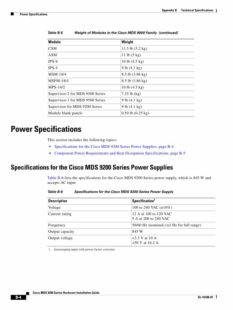
Appendix B Technical Specifications Power Specifications
Power SpecificationsThis section includes the following topics:
• Specifications for the Cisco MDS 9200 Series Power Supplies, page B-4
• Component Power Requirements and Heat Dissipation Specifications, page B-5
Specifications for the Cisco MDS 9200 Series Power SuppliesTable B-6 lists the specifications for the Cisco MDS 9200 Series power supply, which is 845 W and accepts AC input.
CSM 11.5 lb (5.2 kg)
ASM 11 lb (5 kg)
IPS-8 10 lb (4.5 kg)
IPS-4 9 lb (4.1 kg)
MSM-18/4 8.5 lb (3.86 kg)
MSFM-18/4 8.5 lb (3.86 kg)
MPS-14/2 10 lb (4.5 kg)
Supervisor-2 for MDS 9500 Series 7.25 lb (kg)
Supervisor-1 for MDS 9500 Series 9 lb (4.1 kg)
Supervisor for MDS 9200 Series 9 lb (4.1 kg)
Module blank panels 0.50 lb (0.25 kg)
Table B-5 Weight of Modules in the Cisco MDS 9000 Family (continued)
Module Weight
Table B-6 Specifications for the Cisco MDS 9200 Series Power Supply
Description Specification1
1. Autoranging input with power factor corrector
Voltage 100 to 240 VAC (±10%)
Current rating 12 A at 100 to 120 VAC5 A at 200 to 240 VAC
Frequency 50/60 Hz (nominal) (±3 Hz for full range)
Output capacity 845 W
Output voltage +3.3 V at 10 A+50 V at 16.2 A
B-4Cisco MDS 9200 Series Hardware Installation Guide
OL-16188-01
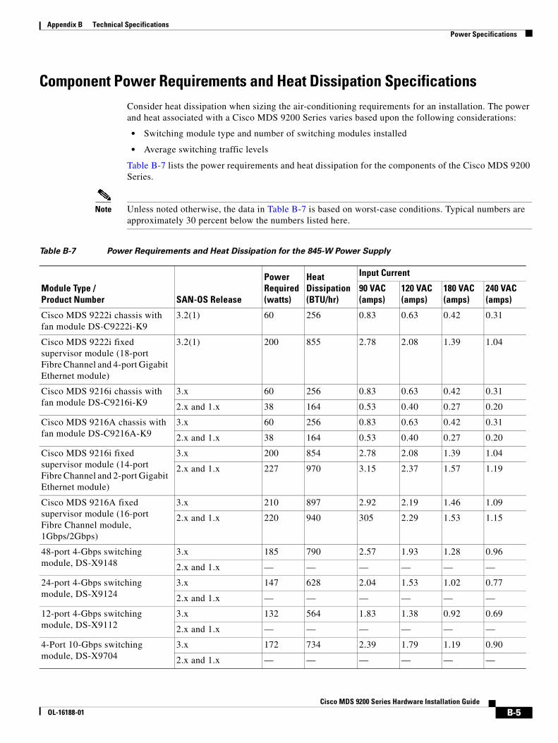
Appendix B Technical Specifications Power Specifications
Component Power Requirements and Heat Dissipation SpecificationsConsider heat dissipation when sizing the air-conditioning requirements for an installation. The power and heat associated with a Cisco MDS 9200 Series varies based upon the following considerations:
• Switching module type and number of switching modules installed
• Average switching traffic levels
Table B-7 lists the power requirements and heat dissipation for the components of the Cisco MDS 9200 Series.
Note Unless noted otherwise, the data in Table B-7 is based on worst-case conditions. Typical numbers are approximately 30 percent below the numbers listed here.
Table B-7 Power Requirements and Heat Dissipation for the 845-W Power Supply
Module Type / Product Number SAN-OS Release
Power Required (watts)
Heat Dissipation (BTU/hr)
Input Current
90 VAC (amps)
120 VAC (amps)
180 VAC (amps)
240 VAC (amps)
Cisco MDS 9222i chassis with fan module DS-C9222i-K9
3.2(1) 60 256 0.83 0.63 0.42 0.31
Cisco MDS 9222i fixed supervisor module (18-port Fibre Channel and 4-port Gigabit Ethernet module)
3.2(1) 200 855 2.78 2.08 1.39 1.04
Cisco MDS 9216i chassis with fan module DS-C9216i-K9
3.x 60 256 0.83 0.63 0.42 0.31
2.x and 1.x 38 164 0.53 0.40 0.27 0.20
Cisco MDS 9216A chassis with fan module DS-C9216A-K9
3.x 60 256 0.83 0.63 0.42 0.31
2.x and 1.x 38 164 0.53 0.40 0.27 0.20
Cisco MDS 9216i fixed supervisor module (14-port Fibre Channel and 2-port Gigabit Ethernet module)
3.x 200 854 2.78 2.08 1.39 1.04
2.x and 1.x 227 970 3.15 2.37 1.57 1.19
Cisco MDS 9216A fixed supervisor module (16-port Fibre Channel module, 1Gbps/2Gbps)
3.x 210 897 2.92 2.19 1.46 1.09
2.x and 1.x 220 940 305 2.29 1.53 1.15
48-port 4-Gbps switching module, DS-X9148
3.x 185 790 2.57 1.93 1.28 0.96
2.x and 1.x — — — — — —
24-port 4-Gbps switching module, DS-X9124
3.x 147 628 2.04 1.53 1.02 0.77
2.x and 1.x — — — — — —
12-port 4-Gbps switching module, DS-X9112
3.x 132 564 1.83 1.38 0.92 0.69
2.x and 1.x — — — — — —
4-Port 10-Gbps switching module, DS-X9704
3.x 172 734 2.39 1.79 1.19 0.90
2.x and 1.x — — — — — —
B-5Cisco MDS 9200 Series Hardware Installation Guide
OL-16188-01
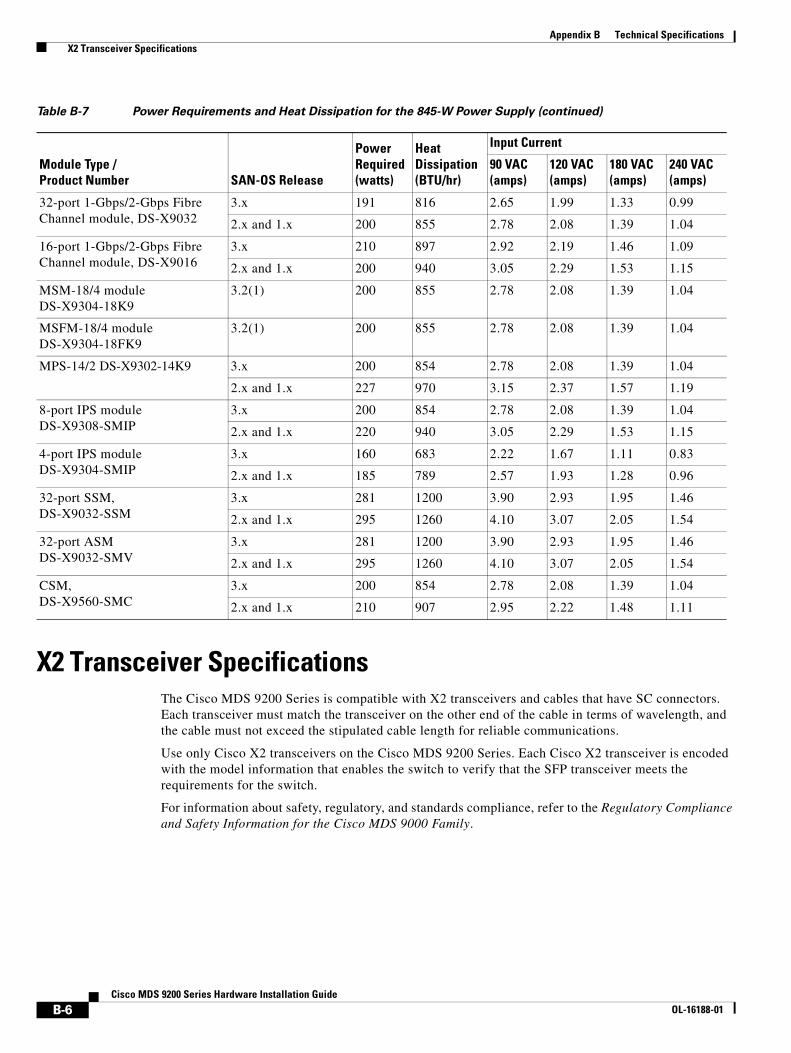
Appendix B Technical Specifications X2 Transceiver Specifications
X2 Transceiver SpecificationsThe Cisco MDS 9200 Series is compatible with X2 transceivers and cables that have SC connectors. Each transceiver must match the transceiver on the other end of the cable in terms of wavelength, and the cable must not exceed the stipulated cable length for reliable communications.
Use only Cisco X2 transceivers on the Cisco MDS 9200 Series. Each Cisco X2 transceiver is encoded with the model information that enables the switch to verify that the SFP transceiver meets the requirements for the switch.
For information about safety, regulatory, and standards compliance, refer to the Regulatory Compliance and Safety Information for the Cisco MDS 9000 Family.
32-port 1-Gbps/2-Gbps Fibre Channel module, DS-X9032
3.x 191 816 2.65 1.99 1.33 0.99
2.x and 1.x 200 855 2.78 2.08 1.39 1.04
16-port 1-Gbps/2-Gbps Fibre Channel module, DS-X9016
3.x 210 897 2.92 2.19 1.46 1.09
2.x and 1.x 200 940 3.05 2.29 1.53 1.15
MSM-18/4 module DS-X9304-18K9
3.2(1) 200 855 2.78 2.08 1.39 1.04
MSFM-18/4 module DS-X9304-18FK9
3.2(1) 200 855 2.78 2.08 1.39 1.04
MPS-14/2 DS-X9302-14K9 3.x 200 854 2.78 2.08 1.39 1.04
2.x and 1.x 227 970 3.15 2.37 1.57 1.19
8-port IPS moduleDS-X9308-SMIP
3.x 200 854 2.78 2.08 1.39 1.04
2.x and 1.x 220 940 3.05 2.29 1.53 1.15
4-port IPS moduleDS-X9304-SMIP
3.x 160 683 2.22 1.67 1.11 0.83
2.x and 1.x 185 789 2.57 1.93 1.28 0.96
32-port SSM,DS-X9032-SSM
3.x 281 1200 3.90 2.93 1.95 1.46
2.x and 1.x 295 1260 4.10 3.07 2.05 1.54
32-port ASMDS-X9032-SMV
3.x 281 1200 3.90 2.93 1.95 1.46
2.x and 1.x 295 1260 4.10 3.07 2.05 1.54
CSM,DS-X9560-SMC
3.x 200 854 2.78 2.08 1.39 1.04
2.x and 1.x 210 907 2.95 2.22 1.48 1.11
Table B-7 Power Requirements and Heat Dissipation for the 845-W Power Supply (continued)
Module Type / Product Number SAN-OS Release
Power Required (watts)
Heat Dissipation (BTU/hr)
Input Current
90 VAC (amps)
120 VAC (amps)
180 VAC (amps)
240 VAC (amps)
B-6Cisco MDS 9200 Series Hardware Installation Guide
OL-16188-01
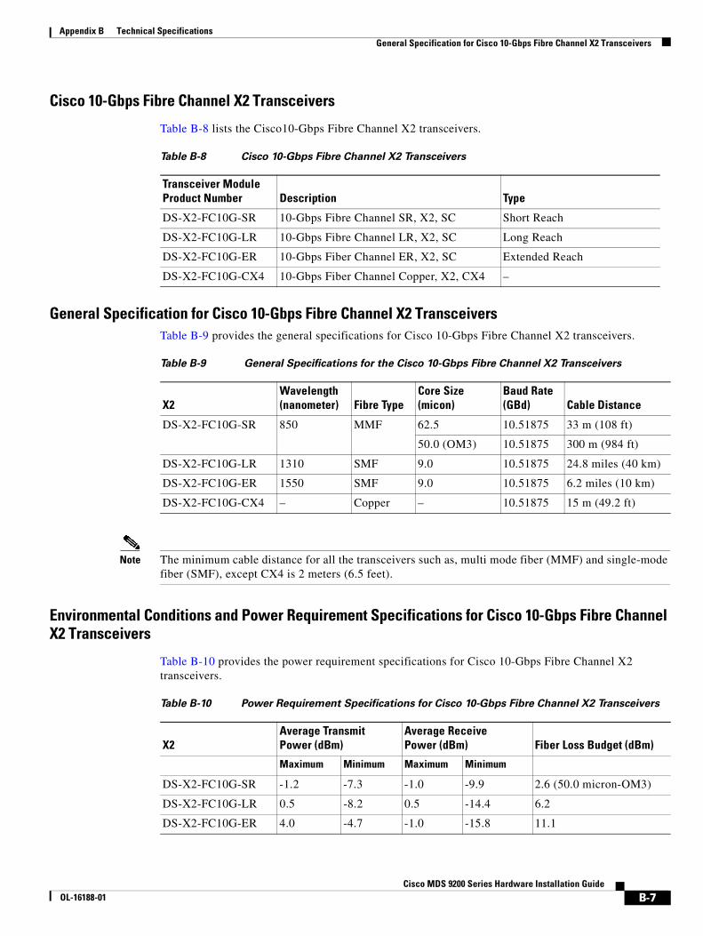
Appendix B Technical Specifications General Specification for Cisco 10-Gbps Fibre Channel X2 Transceivers
Cisco 10-Gbps Fibre Channel X2 Transceivers
Table B-8 lists the Cisco10-Gbps Fibre Channel X2 transceivers.
General Specification for Cisco 10-Gbps Fibre Channel X2 TransceiversTable B-9 provides the general specifications for Cisco 10-Gbps Fibre Channel X2 transceivers.
Note The minimum cable distance for all the transceivers such as, multi mode fiber (MMF) and single-mode fiber (SMF), except CX4 is 2 meters (6.5 feet).
Environmental Conditions and Power Requirement Specifications for Cisco 10-Gbps Fibre Channel X2 Transceivers
Table B-10 provides the power requirement specifications for Cisco 10-Gbps Fibre Channel X2 transceivers.
Table B-8 Cisco 10-Gbps Fibre Channel X2 Transceivers
Transceiver Module Product Number Description Type
DS-X2-FC10G-SR 10-Gbps Fibre Channel SR, X2, SC Short Reach
DS-X2-FC10G-LR 10-Gbps Fibre Channel LR, X2, SC Long Reach
DS-X2-FC10G-ER 10-Gbps Fiber Channel ER, X2, SC Extended Reach
DS-X2-FC10G-CX4 10-Gbps Fiber Channel Copper, X2, CX4 –
Table B-9 General Specifications for the Cisco 10-Gbps Fibre Channel X2 Transceivers
X2Wavelength (nanometer) Fibre Type
Core Size(micon)
Baud Rate(GBd) Cable Distance
DS-X2-FC10G-SR 850 MMF 62.5 10.51875 33 m (108 ft)
50.0 (OM3) 10.51875 300 m (984 ft)
DS-X2-FC10G-LR 1310 SMF 9.0 10.51875 24.8 miles (40 km)
DS-X2-FC10G-ER 1550 SMF 9.0 10.51875 6.2 miles (10 km)
DS-X2-FC10G-CX4 – Copper – 10.51875 15 m (49.2 ft)
Table B-10 Power Requirement Specifications for Cisco 10-Gbps Fibre Channel X2 Transceivers
X2Average Transmit Power (dBm)
Average Receive Power (dBm) Fiber Loss Budget (dBm)
Maximum Minimum Maximum Minimum
DS-X2-FC10G-SR -1.2 -7.3 -1.0 -9.9 2.6 (50.0 micron-OM3)
DS-X2-FC10G-LR 0.5 -8.2 0.5 -14.4 6.2
DS-X2-FC10G-ER 4.0 -4.7 -1.0 -15.8 11.1
B-7Cisco MDS 9200 Series Hardware Installation Guide
OL-16188-01

Appendix B Technical Specifications General Specification for Cisco 10-Gbps Fibre Channel X2 Transceivers
Note DS-X2-FC10G-CX4 is not an optical module; therefore, it is not listed in Table B-10.
Table B-11 provides the environmental specifications for the Cisco 10-Gbps Fibre Channel X2 transceivers.
For information about safety, regulatory, and standards compliance, refer to the Regulatory Compliance and Safety Information for the Cisco MDS 9000 Family.
Cisco 10-Gbps Ethernet X2 Transceivers
Table B-12 lists the Cisco 10-Gbps Ethernet X2 transceivers.
General Specification for Cisco 10-Gbps Ethernet X2 Transceivers
Table B-13 provides the general specifications for Cisco 10-Gbps Ethernet X2 transceivers.
Note The minimum cable distance for the MMF transceiver listed above is 2 meters (6.5 feet).
Table B-11 Environmental Specifications for the Cisco 10- Gbps Fibre Channel X2 Transceivers
X2 Operating Storage
Maximum Minimum Maximum Minimum
DS-X2-FC10G-SR 40°C 0°C 85°C -40°C
DS-X2-FC10G-LR 40°C 0°C 85°C -40°C
DS-X2-FC10G-ER 40°C 0°C 85°C -40°C
DS-X2-FC10G-CX4 40°C 0°C 85°C -40°C
Table B-12 Cisco 10-Gbps Ethernet X2 Transceivers
Transceiver Module Product Number Description Type
DS-X2-E10G-SR 10-Gbps Ethernet Short Reach, X2, SC Short reach
Table B-13 General Specifications for the Cisco 10-Gbps Ethernet X2 Transceivers
X2Wavelength (nanometer) Fiber Type
Core Size(micon)
Baud Rate(GBd) Cable Distance
DS-X2-E10G-SR 850 MMF 62.5 10.3125 33 (108 ft)
50.0 (OM3) 10.3125 300 (984 ft)
B-8Cisco MDS 9200 Series Hardware Installation Guide
OL-16188-01
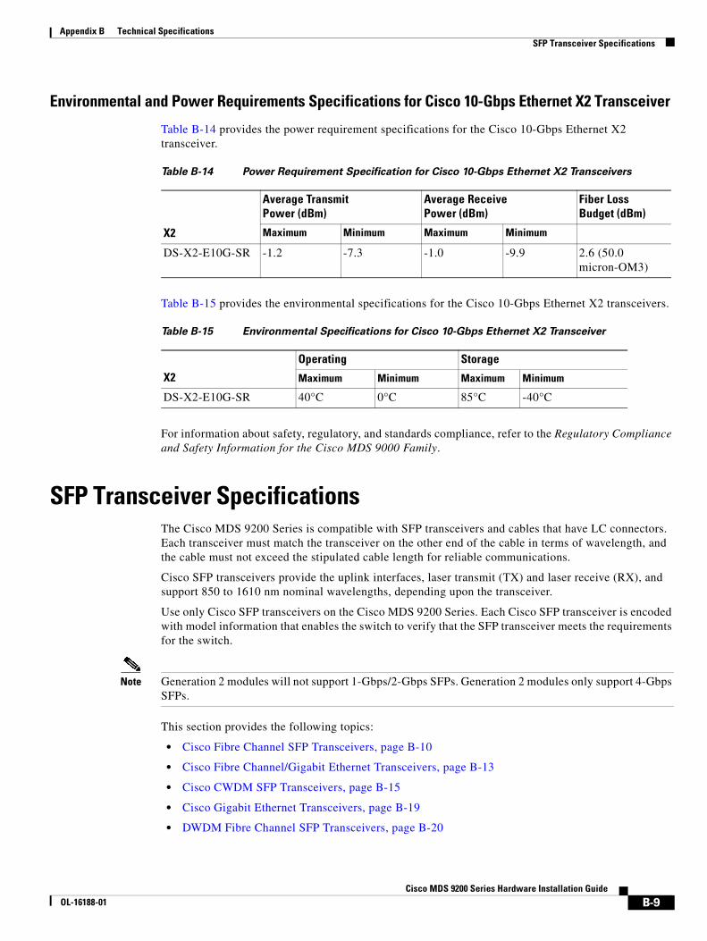
Appendix B Technical Specifications SFP Transceiver Specifications
Environmental and Power Requirements Specifications for Cisco 10-Gbps Ethernet X2 Transceiver
Table B-14 provides the power requirement specifications for the Cisco 10-Gbps Ethernet X2 transceiver.
Table B-15 provides the environmental specifications for the Cisco 10-Gbps Ethernet X2 transceivers.
For information about safety, regulatory, and standards compliance, refer to the Regulatory Compliance and Safety Information for the Cisco MDS 9000 Family.
SFP Transceiver SpecificationsThe Cisco MDS 9200 Series is compatible with SFP transceivers and cables that have LC connectors. Each transceiver must match the transceiver on the other end of the cable in terms of wavelength, and the cable must not exceed the stipulated cable length for reliable communications.
Cisco SFP transceivers provide the uplink interfaces, laser transmit (TX) and laser receive (RX), and support 850 to 1610 nm nominal wavelengths, depending upon the transceiver.
Use only Cisco SFP transceivers on the Cisco MDS 9200 Series. Each Cisco SFP transceiver is encoded with model information that enables the switch to verify that the SFP transceiver meets the requirements for the switch.
Note Generation 2 modules will not support 1-Gbps/2-Gbps SFPs. Generation 2 modules only support 4-Gbps SFPs.
This section provides the following topics:
• Cisco Fibre Channel SFP Transceivers, page B-10
• Cisco Fibre Channel/Gigabit Ethernet Transceivers, page B-13
• Cisco CWDM SFP Transceivers, page B-15
• Cisco Gigabit Ethernet Transceivers, page B-19
• DWDM Fibre Channel SFP Transceivers, page B-20
Table B-14 Power Requirement Specification for Cisco 10-Gbps Ethernet X2 Transceivers
X2
Average Transmit Power (dBm)
Average Receive Power (dBm)
Fiber Loss Budget (dBm)
Maximum Minimum Maximum Minimum
DS-X2-E10G-SR -1.2 -7.3 -1.0 -9.9 2.6 (50.0 micron-OM3)
Table B-15 Environmental Specifications for Cisco 10-Gbps Ethernet X2 Transceiver
X2
Operating Storage
Maximum Minimum Maximum Minimum
DS-X2-E10G-SR 40°C 0°C 85°C -40°C
B-9Cisco MDS 9200 Series Hardware Installation Guide
OL-16188-01

Appendix B Technical Specifications SFP Transceiver Specifications
Cisco Fibre Channel SFP TransceiversTable B-16 lists the Cisco 2-Gbps and 4-Gbps Fibre Channel SFP transceivers.
General Specifications for Cisco 4-Gbps Fibre Channel SFP Transceivers
Table B-17 provides the general specifications for Cisco Fibre Channel SFP transceivers.
Note The minimum cable distance for all the transceivers, such as MMF and SMF, is 2 meters (6.5 feet).
Table B-16 Cisco 2-Gbps and 4-Gbps Fibre Channel SFP Transceivers
Transceiver ModuleProduct Number Description Type
DS-SFP-FC4G-SW 1/2/4-Gbps Fibre Channel SW, SFP, LC Short wavelength
DS-SFP-FC4G-MR 1/2/4-Gbps Fibre Channel LW 4-km, SFP, LC Long wavelength
DS-SFP-FC4G-LW 1/2/4-Gbps Fibre Channel LW 10-km, SFP, LC Long wavelength
DS-SFP-FC-2G-SW 1/2-Gbps Fibre Channel SW, SFP, LC Short wavelength
DS-SFP-FC-2G-LW 1/2-Gbps Fibre Channel LW, SFP, LC Long wavelength
Table B-17 General Specifications for Cisco 4-Gbps Fibre Channel SFP Transceivers
SFPWavelength (nanometer) Fibre Type
Core Size(micon)
Baud Rate(GBd)
Cable Distance(meter)
DS-SFP-FC4G-SW 850 MMF 62.5 1.0625 300 m (984 ft)
62.5 2.125 150 m (492 ft)
62.5 4.250 70 m (230 ft)
50.0 (OM2) 1.0625 500 m (1640 ft)
50.0 (OM2) 2.125 300 m (984 ft)
50.0(OM2) 4.250 150 m (492 ft)
50. 0 (OM3) 1.0625 860 m (2821 ft)
50. 0 (OM3) 2.125 500 m (1640 ft)
50. 0 (OM3) 4.250 380 m (1246 ft)
DS-SFP-FC4G-MR 1310 SMF 9.0 1.0625 6.2 miles (10 km)
9.0 2.125 2.4 miles (4 km)
9.0 4.250 2.4 miles (4 km)
DS-SFP-FC4G-LW 1310 SMF 9.0 1.0625 6.2 miles (10 km)
9.0 2.125 6.2 miles (10 km)
9.0 4.250 2.4 miles (4 km)
B-10Cisco MDS 9200 Series Hardware Installation Guide
OL-16188-01
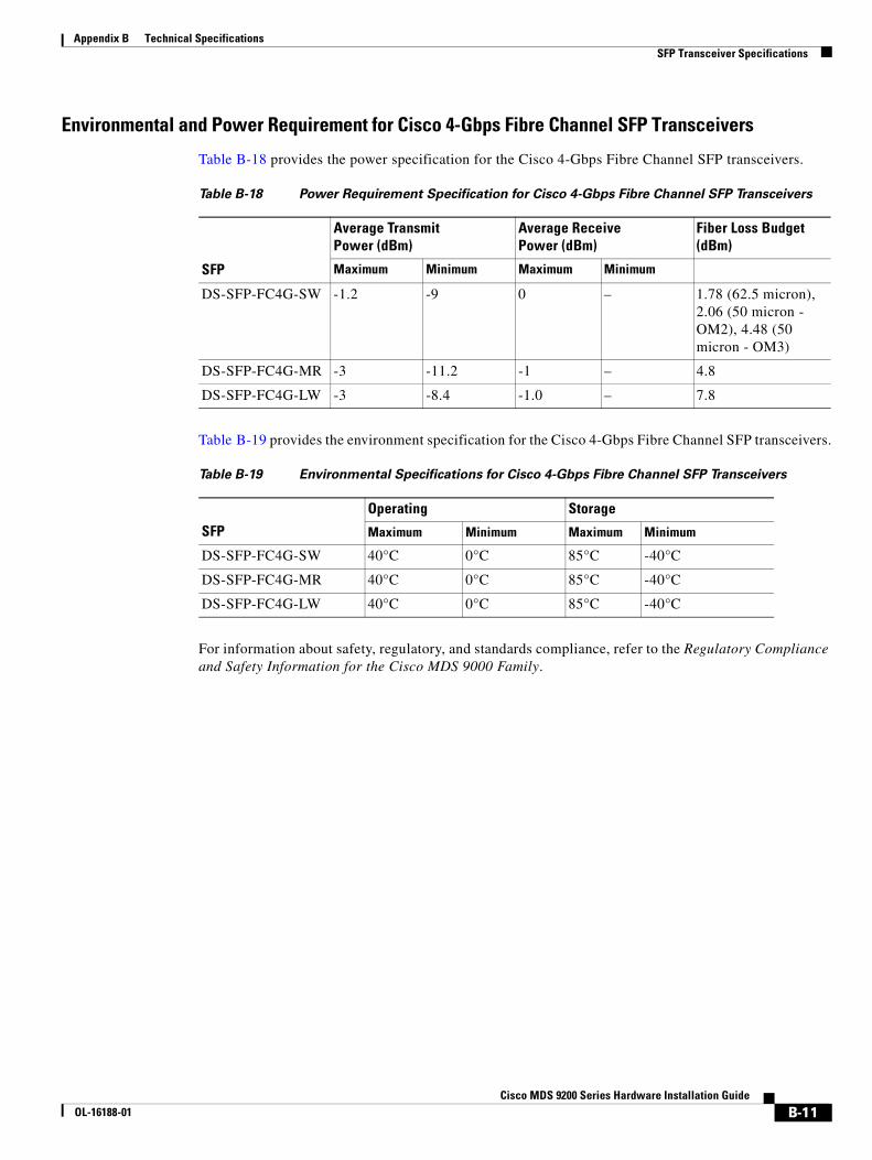
Appendix B Technical Specifications SFP Transceiver Specifications
Environmental and Power Requirement for Cisco 4-Gbps Fibre Channel SFP Transceivers
Table B-18 provides the power specification for the Cisco 4-Gbps Fibre Channel SFP transceivers.
Table B-19 provides the environment specification for the Cisco 4-Gbps Fibre Channel SFP transceivers.
For information about safety, regulatory, and standards compliance, refer to the Regulatory Compliance and Safety Information for the Cisco MDS 9000 Family.
Table B-18 Power Requirement Specification for Cisco 4-Gbps Fibre Channel SFP Transceivers
SFP
Average Transmit Power (dBm)
Average Receive Power (dBm)
Fiber Loss Budget (dBm)
Maximum Minimum Maximum Minimum
DS-SFP-FC4G-SW -1.2 -9 0 – 1.78 (62.5 micron), 2.06 (50 micron - OM2), 4.48 (50 micron - OM3)
DS-SFP-FC4G-MR -3 -11.2 -1 – 4.8
DS-SFP-FC4G-LW -3 -8.4 -1.0 – 7.8
Table B-19 Environmental Specifications for Cisco 4-Gbps Fibre Channel SFP Transceivers
SFP
Operating Storage
Maximum Minimum Maximum Minimum
DS-SFP-FC4G-SW 40°C 0°C 85°C -40°C
DS-SFP-FC4G-MR 40°C 0°C 85°C -40°C
DS-SFP-FC4G-LW 40°C 0°C 85°C -40°C
B-11Cisco MDS 9200 Series Hardware Installation Guide
OL-16188-01

Appendix B Technical Specifications SFP Transceiver Specifications
General Specifications for Cisco 2-Gbps Fibre Channel SFP Transceivers
Table B-20 provides general specification for the 4-Gbps Fibre Channel SFP transceiver.
Note The minimum cable distance for both the transceivers such as MMF and SMF is 2 meters (6.5 feet).
Environmental and Power Requirement for Cisco 2-Gbps Fibre Channel SFP Transceivers
Table B-21 provides the power specification for Cisco 2-Gbps Fibre Channel SFP transceivers.
Table B-22 provides the environmental specification for Cisco 2-Gbps Fibre Channel SFP transceivers.
For information about safety, regulatory, and standards compliance, refer to the Regulatory Compliance and Safety Information for the Cisco MDS 9000 Family.
Table B-20 General Specifications for Cisco 4-Gbps Fibre Channel SFP Transceivers
SFPWavelength (nanometer) Fibre Type
Core Size(micon)
Baud Rate(GBd)
Cable Distance(meter)
DS-SFP-FC-2G-SW 850 MMF 62.5 1.0625 300 m (984 ft)
62.5 2.125 150 m (492 ft)
50.0 (OM2) 1.0625 500 m (1640 ft)
50.0 (OM) 2.125 300 m (984 ft)
DS-SFP-FC-2G-LW 1310 SMF 9.0 1.0625 6.2 miles (10 km)
9.0 2.125 6.2 miles (10 km)
Table B-21 Power Requirement Specification for Cisco 2-Gbps Fibre Channel SFP Transceivers
SFP
Average Transmit Power (dBm)
Average Receive Power (dBm)
Fiber Loss Budget (dBm)
Maximum Minimum Maximum Minimum
DS-SFP-FC-2G-SW -1.2 -10.0 0 – 2.1 (62.5 micron), 2.62 (50 micron -OM2)
DS-SFP-FC-2G-LW -3 -11.7 -3 – 7.8
Table B-22 Environmental Specifications for Cisco 2-Gbps Fibre Channel SFP Transceivers
SFP
Operating Storage
Maximum Minimum Maximum Minimum
DS-SFP-FC-2G-SW 40°C 0°C 85°C -40°C
DS-SFP-FC-2G-LW 40°C 0°C 85°C -40°C
B-12Cisco MDS 9200 Series Hardware Installation Guide
OL-16188-01
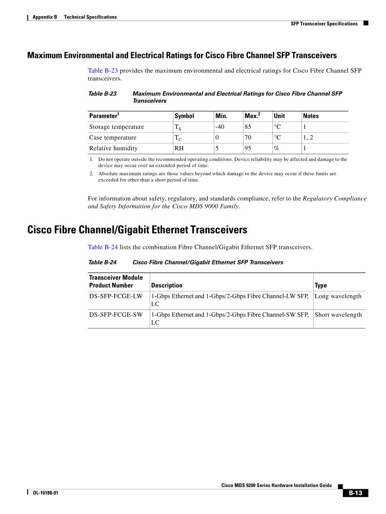
Appendix B Technical Specifications SFP Transceiver Specifications
Maximum Environmental and Electrical Ratings for Cisco Fibre Channel SFP Transceivers
Table B-23 provides the maximum environmental and electrical ratings for Cisco Fibre Channel SFP transceivers.
For information about safety, regulatory, and standards compliance, refer to the Regulatory Compliance and Safety Information for the Cisco MDS 9000 Family.
Cisco Fibre Channel/Gigabit Ethernet TransceiversTable B-24 lists the combination Fibre Channel/Gigabit Ethernet SFP transceivers.
Table B-23 Maximum Environmental and Electrical Ratings for Cisco Fibre Channel SFP
Transceivers
Parameter1
1. Do not operate outside the recommended operating conditions. Device reliability may be affected and damage to the device may occur over an extended period of time.
Symbol Min. Max.2
2. Absolute maximum ratings are those values beyond which damage to the device may occur if these limits are exceeded for other than a short period of time.
Unit Notes
Storage temperature TS -40 85 °C 1
Case temperature TC 0 70 °C 1, 2
Relative humidity RH 5 95 % 1
Table B-24 Cisco Fibre Channel/Gigabit Ethernet SFP Transceivers
Transceiver Module Product Number Description Type
DS-SFP-FCGE-LW 1-Gbps Ethernet and 1-Gbps/2-Gbps Fibre Channel-LW SFP,
LC
Long wavelength
DS-SFP-FCGE-SW 1-Gbps Ethernet and 1-Gbps/2-Gbps Fibre Channel-SW SFP,
LC
Short wavelength
B-13Cisco MDS 9200 Series Hardware Installation Guide
OL-16188-01
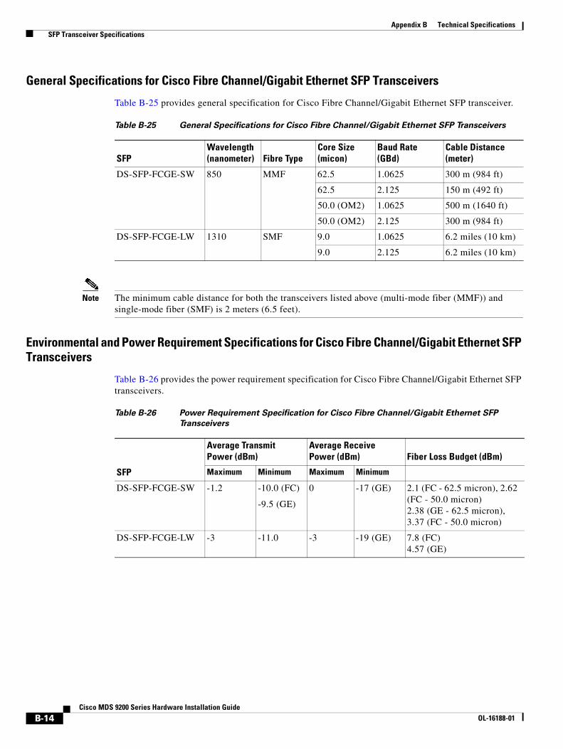
Appendix B Technical Specifications SFP Transceiver Specifications
General Specifications for Cisco Fibre Channel/Gigabit Ethernet SFP Transceivers
Table B-25 provides general specification for Cisco Fibre Channel/Gigabit Ethernet SFP transceiver.
Note The minimum cable distance for both the transceivers listed above (multi-mode fiber (MMF)) and single-mode fiber (SMF) is 2 meters (6.5 feet).
Environmental and Power Requirement Specifications for Cisco Fibre Channel/Gigabit Ethernet SFP Transceivers
Table B-26 provides the power requirement specification for Cisco Fibre Channel/Gigabit Ethernet SFP transceivers.
Table B-25 General Specifications for Cisco Fibre Channel/Gigabit Ethernet SFP Transceivers
SFPWavelength (nanometer) Fibre Type
Core Size(micon)
Baud Rate(GBd)
Cable Distance(meter)
DS-SFP-FCGE-SW 850 MMF 62.5 1.0625 300 m (984 ft)
62.5 2.125 150 m (492 ft)
50.0 (OM2) 1.0625 500 m (1640 ft)
50.0 (OM2) 2.125 300 m (984 ft)
DS-SFP-FCGE-LW 1310 SMF 9.0 1.0625 6.2 miles (10 km)
9.0 2.125 6.2 miles (10 km)
Table B-26 Power Requirement Specification for Cisco Fibre Channel/Gigabit Ethernet SFP
Transceivers
SFP
Average Transmit Power (dBm)
Average Receive Power (dBm) Fiber Loss Budget (dBm)
Maximum Minimum Maximum Minimum
DS-SFP-FCGE-SW -1.2 -10.0 (FC)
-9.5 (GE)
0 -17 (GE) 2.1 (FC - 62.5 micron), 2.62 (FC - 50.0 micron)2.38 (GE - 62.5 micron), 3.37 (FC - 50.0 micron)
DS-SFP-FCGE-LW -3 -11.0 -3 -19 (GE) 7.8 (FC)4.57 (GE)
B-14Cisco MDS 9200 Series Hardware Installation Guide
OL-16188-01

Appendix B Technical Specifications SFP Transceiver Specifications
Table B-27 provides the environmental specification for Cisco Fibre Channel/Gigabit Ethernet SFP transceivers.
For information about safety, regulatory, and standards compliance, refer to the Regulatory Compliance and Safety Information for the Cisco MDS 9000 Family.
Cisco CWDM SFP TransceiversTable B-28 lists the Cisco 1-Gbps and 2-Gbps CWDM SFP transceivers.
Table B-27 Environmental Specifications for Cisco Fibre Channel/Gigabit Ethernet SFP
Transceivers
SFP
Operating Storage
Maximum Minimum Maximum Minimum
DS-SFP-FCGE-SW 40°C 0°C 85°C -40°C
DS-SFP-FCGE-LW 40°C 0°C 85°C -40°C
Table B-28 Cisco 1-Gbps and 2-Gbps CWDM SFP Transceivers
Description Color
Cisco CWDM SFP 1470 nm; Gigabit Ethernet and 1-Gbps/2-Gbps FC Gray
Cisco CWDM SFP 1490 nm; Gigabit Ethernet and 1-Gbps/2-Gbps FC Violet
Cisco CWDM SFP 1510 nm; Gigabit Ethernet and 1-Gbps/2-Gbps FC Blue
Cisco CWDM SFP 1530 nm; Gigabit Ethernet and 1-Gbps/2-Gbps FC Green
Cisco CWDM SFP 1550 nm; Gigabit Ethernet and 1-Gbps/2-Gbps FC Yellow
Cisco CWDM SFP 1570 nm; Gigabit Ethernet and 1-Gbps/2-Gbps FC Orange
Cisco CWDM SFP 1590 nm; Gigabit Ethernet and 1-Gbps/2-Gbps FC Red
Cisco CWDM SFP 1610 nm; Gigabit Ethernet and 1-Gbps/2-Gbps FC Brown
B-15Cisco MDS 9200 Series Hardware Installation Guide
OL-16188-01
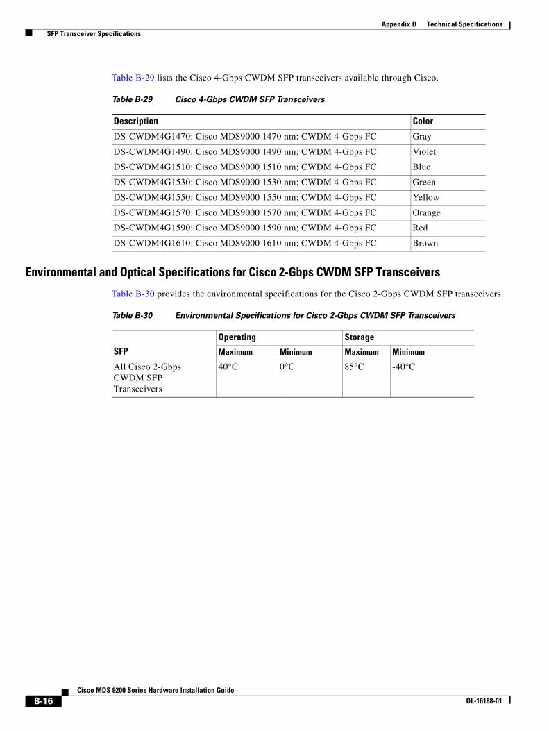
Appendix B Technical Specifications SFP Transceiver Specifications
Table B-29 lists the Cisco 4-Gbps CWDM SFP transceivers available through Cisco.
Environmental and Optical Specifications for Cisco 2-Gbps CWDM SFP Transceivers
Table B-30 provides the environmental specifications for the Cisco 2-Gbps CWDM SFP transceivers.
Table B-29 Cisco 4-Gbps CWDM SFP Transceivers
Description Color
DS-CWDM4G1470: Cisco MDS9000 1470 nm; CWDM 4-Gbps FC Gray
DS-CWDM4G1490: Cisco MDS9000 1490 nm; CWDM 4-Gbps FC Violet
DS-CWDM4G1510: Cisco MDS9000 1510 nm; CWDM 4-Gbps FC Blue
DS-CWDM4G1530: Cisco MDS9000 1530 nm; CWDM 4-Gbps FC Green
DS-CWDM4G1550: Cisco MDS9000 1550 nm; CWDM 4-Gbps FC Yellow
DS-CWDM4G1570: Cisco MDS9000 1570 nm; CWDM 4-Gbps FC Orange
DS-CWDM4G1590: Cisco MDS9000 1590 nm; CWDM 4-Gbps FC Red
DS-CWDM4G1610: Cisco MDS9000 1610 nm; CWDM 4-Gbps FC Brown
Table B-30 Environmental Specifications for Cisco 2-Gbps CWDM SFP Transceivers
SFP
Operating Storage
Maximum Minimum Maximum Minimum
All Cisco 2-Gbps CWDM SFP Transceivers
40°C 0°C 85°C -40°C
B-16Cisco MDS 9200 Series Hardware Installation Guide
OL-16188-01
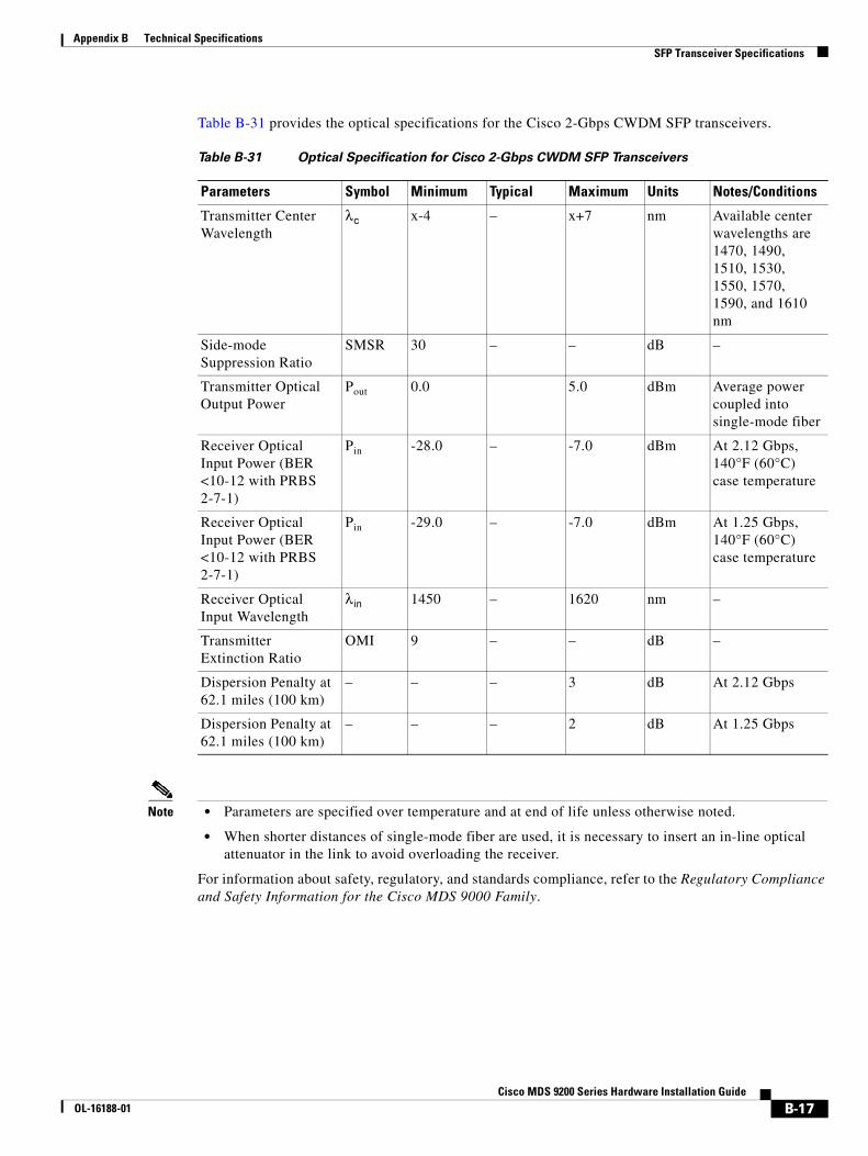
Appendix B Technical Specifications SFP Transceiver Specifications
Table B-31 provides the optical specifications for the Cisco 2-Gbps CWDM SFP transceivers.
Note • Parameters are specified over temperature and at end of life unless otherwise noted.
• When shorter distances of single-mode fiber are used, it is necessary to insert an in-line optical attenuator in the link to avoid overloading the receiver.
For information about safety, regulatory, and standards compliance, refer to the Regulatory Compliance and Safety Information for the Cisco MDS 9000 Family.
Table B-31 Optical Specification for Cisco 2-Gbps CWDM SFP Transceivers
Parameters Symbol Minimum Typical Maximum Units Notes/Conditions
Transmitter Center Wavelength
λc x-4 – x+7 nm Available center wavelengths are 1470, 1490, 1510, 1530, 1550, 1570, 1590, and 1610 nm
Side-mode Suppression Ratio
SMSR 30 – – dB –
Transmitter Optical Output Power
Pout 0.0 5.0 dBm Average power coupled into single-mode fiber
Receiver Optical Input Power (BER <10-12 with PRBS 2-7-1)
Pin -28.0 – -7.0 dBm At 2.12 Gbps, 140°F (60°C) case temperature
Receiver Optical Input Power (BER <10-12 with PRBS 2-7-1)
Pin -29.0 – -7.0 dBm At 1.25 Gbps, 140°F (60°C) case temperature
Receiver Optical Input Wavelength
λin 1450 – 1620 nm –
Transmitter Extinction Ratio
OMI 9 – – dB –
Dispersion Penalty at 62.1 miles (100 km)
– – – 3 dB At 2.12 Gbps
Dispersion Penalty at 62.1 miles (100 km)
– – – 2 dB At 1.25 Gbps
B-17Cisco MDS 9200 Series Hardware Installation Guide
OL-16188-01

Appendix B Technical Specifications SFP Transceiver Specifications
Environmental and Optical Specifications for Cisco 4-Gbps CWDM SFP Transceivers
Table B-32 provides the environmental specifications for the Cisco 4-Gbps CWDM SFP transceivers.
Table B-33 provides the optical specifications for Cisco 4-Gbps CWDM SFP transceivers.
Note • In typical point-to-point deployments, all wavelengths have a minimum reach of 24.8 miles (40 km).
• Parameters are specified over temperature and at end of life unless otherwise noted.
• When shorter distances of single-mode fiber are used, it is necessary to insert an in-line optical attenuator in the link to avoid overloading the receiver.
• A maximum of 24 4-Gbps CWDM SFPs are supported in a single MDS switching module.
Table B-32 Environmental Specifications for Cisco 4-Gbps CWDM SFP Transceivers
SFP
Operating Storage
Maximum Minimum Maximum Minimum
All Cisco 4-Gbps CWDM SFP Transceivers
40°C 0°C 85°C -40°C
Table B-33 Optical Specification for Cisco 4-Gbps CWDM SFP Transceivers
Parameters Symbol Minimum Typical Maximum Units Notes/Conditions
Transmitter Center Wavelength
λc (x-6) x x+6 nm Available center wavelengths are 1470, 1490, 1510, 1530, 1550, 1570, 1590, and 1610 nm
Side-mode Suppression Ratio
SMSR 30 – – dB –
Transmitter Optical Output Power
Pout 1.0 – 5.0 dBm Average power coupled into single-mode fiber
Receiver Optical Input Power (BER <10-12 with PRBS 2-23-1)
Pin -15.7 – 0.0 dBm 140°F (60°C) case temperature
Link Budget – 17.8 – – dB –
Receiver Optical Input Wavelength
λin 1450 – 1620 nm –
Transmitter Extinction Ratio
OMI 4 – – dB –
Dispersion Penalty at 15.5 miles (25 km)
– – – 3 dB –
B-18Cisco MDS 9200 Series Hardware Installation Guide
OL-16188-01
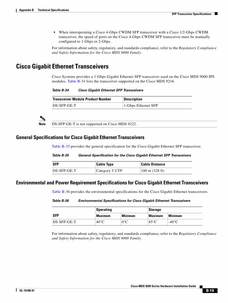
Appendix B Technical Specifications SFP Transceiver Specifications
• When interoperating a Cisco 4-Gbps CWDM SFP transceiver with a Cisco 1/2-Gbps CWDM transceiver, the speed of ports on the Cisco 4-Gbps CWDM SFP transceiver must be manually configured to 1-Gbps or 2-Gbps.
For information about safety, regulatory, and standards compliance, refer to the Regulatory Compliance and Safety Information for the Cisco MDS 9000 Family.
Cisco Gigabit Ethernet TransceiversCisco Systems provides a 1-Gbps Gigabit Ethernet SFP transceiver used on the Cisco MDS 9000 IPS modules. Table B-34 lists the transceiver supported on the Cisco MDS 9216.
Note DS-SFP-GE-T is not supported on Cisco MDS 9222.
General Specifications for Cisco Gigabit Ethernet Transceivers
Table B-35 provides the general specification for the Cisco Gigabit Ethernet SFP transceiver.
Environmental and Power Requirement Specifications for Cisco Gigabit Ethernet Transceivers
Table B-36 provides the environmental specifications for the Cisco Gigabit Ethernet transceivers.
For information about safety, regulatory, and standards compliance, refer to the Regulatory Compliance and Safety Information for the Cisco MDS 9000 Family.
Table B-34 Cisco Gigabit Ethernet SFP Transceivers
Transceiver Module Product Number Description
DS-SFP-GE-T 1-Gbps Ethernet SFP
Table B-35 General Specification for the Cisco Gigabit Ethernet SFP Transceivers
SFP Cable Type Cable Distance
DS-SFP-GE-T Category 5 UTP 100 m (328 ft)
Table B-36 Environmental Specifications for Cisco Gigabit Ethernet Transceivers
SFP
Operating Storage
Maximum Minimum Maximum Minimum
DS-SFP-GE-T 40°C 0°C 85°C -40°C
B-19Cisco MDS 9200 Series Hardware Installation Guide
OL-16188-01
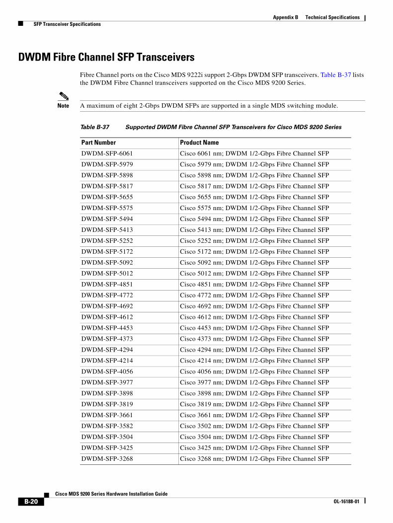
Appendix B Technical Specifications SFP Transceiver Specifications
DWDM Fibre Channel SFP TransceiversFibre Channel ports on the Cisco MDS 9222i support 2-Gbps DWDM SFP transceivers. Table B-37 lists the DWDM Fibre Channel transceivers supported on the Cisco MDS 9200 Series.
Note A maximum of eight 2-Gbps DWDM SFPs are supported in a single MDS switching module.
Table B-37 Supported DWDM Fibre Channel SFP Transceivers for Cisco MDS 9200 Series
Part Number Product Name
DWDM-SFP-6061 Cisco 6061 nm; DWDM 1/2-Gbps Fibre Channel SFP
DWDM-SFP-5979 Cisco 5979 nm; DWDM 1/2-Gbps Fibre Channel SFP
DWDM-SFP-5898 Cisco 5898 nm; DWDM 1/2-Gbps Fibre Channel SFP
DWDM-SFP-5817 Cisco 5817 nm; DWDM 1/2-Gbps Fibre Channel SFP
DWDM-SFP-5655 Cisco 5655 nm; DWDM 1/2-Gbps Fibre Channel SFP
DWDM-SFP-5575 Cisco 5575 nm; DWDM 1/2-Gbps Fibre Channel SFP
DWDM-SFP-5494 Cisco 5494 nm; DWDM 1/2-Gbps Fibre Channel SFP
DWDM-SFP-5413 Cisco 5413 nm; DWDM 1/2-Gbps Fibre Channel SFP
DWDM-SFP-5252 Cisco 5252 nm; DWDM 1/2-Gbps Fibre Channel SFP
DWDM-SFP-5172 Cisco 5172 nm; DWDM 1/2-Gbps Fibre Channel SFP
DWDM-SFP-5092 Cisco 5092 nm; DWDM 1/2-Gbps Fibre Channel SFP
DWDM-SFP-5012 Cisco 5012 nm; DWDM 1/2-Gbps Fibre Channel SFP
DWDM-SFP-4851 Cisco 4851 nm; DWDM 1/2-Gbps Fibre Channel SFP
DWDM-SFP-4772 Cisco 4772 nm; DWDM 1/2-Gbps Fibre Channel SFP
DWDM-SFP-4692 Cisco 4692 nm; DWDM 1/2-Gbps Fibre Channel SFP
DWDM-SFP-4612 Cisco 4612 nm; DWDM 1/2-Gbps Fibre Channel SFP
DWDM-SFP-4453 Cisco 4453 nm; DWDM 1/2-Gbps Fibre Channel SFP
DWDM-SFP-4373 Cisco 4373 nm; DWDM 1/2-Gbps Fibre Channel SFP
DWDM-SFP-4294 Cisco 4294 nm; DWDM 1/2-Gbps Fibre Channel SFP
DWDM-SFP-4214 Cisco 4214 nm; DWDM 1/2-Gbps Fibre Channel SFP
DWDM-SFP-4056 Cisco 4056 nm; DWDM 1/2-Gbps Fibre Channel SFP
DWDM-SFP-3977 Cisco 3977 nm; DWDM 1/2-Gbps Fibre Channel SFP
DWDM-SFP-3898 Cisco 3898 nm; DWDM 1/2-Gbps Fibre Channel SFP
DWDM-SFP-3819 Cisco 3819 nm; DWDM 1/2-Gbps Fibre Channel SFP
DWDM-SFP-3661 Cisco 3661 nm; DWDM 1/2-Gbps Fibre Channel SFP
DWDM-SFP-3582 Cisco 3502 nm; DWDM 1/2-Gbps Fibre Channel SFP
DWDM-SFP-3504 Cisco 3504 nm; DWDM 1/2-Gbps Fibre Channel SFP
DWDM-SFP-3425 Cisco 3425 nm; DWDM 1/2-Gbps Fibre Channel SFP
DWDM-SFP-3268 Cisco 3268 nm; DWDM 1/2-Gbps Fibre Channel SFP
B-20Cisco MDS 9200 Series Hardware Installation Guide
OL-16188-01

Appendix B Technical Specifications SFP Transceiver Specifications
DWDM-SFP-3190 Cisco 3190 nm; DWDM 1/2-Gbps Fibre Channel SFP
DWDM-SFP-3112 Cisco 3112 nm; DWDM 1/2-Gbps Fibre Channel SF
DWDM-SFP-3033 Cisco 3033 nm; DWDM 1/2-Gbps Fibre Channel SF
Table B-37 Supported DWDM Fibre Channel SFP Transceivers for Cisco MDS 9200 Series
Part Number Product Name
B-21Cisco MDS 9200 Series Hardware Installation Guide
OL-16188-01

Appendix B Technical Specifications SFP Transceiver Specifications
B-22Cisco MDS 9200 Series Hardware Installation Guide
OL-16188-01
Send documenta t ion comments to mds feedba ck -doc@c i sco .com
Cisco MOL-16188-01
A
P P E N D I X C Cable and Port SpecificationsThis appendix provides cable and port specifications, and includes the following sections:
• Cables and Adapters Provided, page C-1
• Console Port, page C-2
• COM1 Port, page C-3
• MGMT 10/100/1000 Ethernet Port, page C-5
• MGMT 10/100 Ethernet Port, page C-6
• Supported Power Cords and Plugs, page C-8
Cables and Adapters ProvidedThe Cisco MDS 9500 Series accessory kit includes the following items:
• RJ-45 rollover cable
• DB-9F/RJ-45F PC—RJ-45 to DB-9 female DTE adapter (labeled “Terminal”)
• RJ-45/DSUB F/F adapter—RJ-45 to DB-25 female DTE adapter (labeled “Terminal”)
• RJ-45/DSUB R/P adapter—RJ-45 to DB-25 male DCE adapter (labeled “Modem”)
Note Additional cables and adapters can be ordered from your customer service representative.
Note If you purchased Cisco support through a Cisco reseller, contact the reseller directly. If you purchased support directly from Cisco Systems, contact Cisco Technical Support at this URL: http://www.cisco.com/warp/public/687/Directory/DirTAC.shtm
C-1DS 9200 Series Hardware Installation Guide
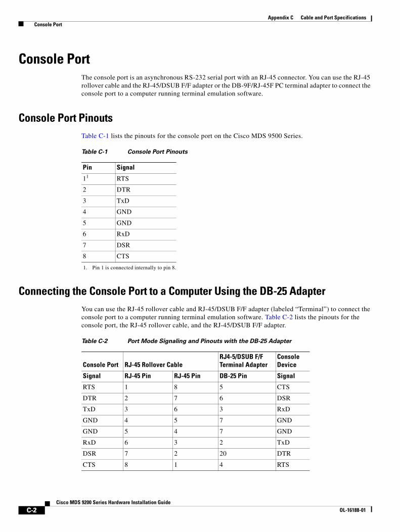
Appendix C Cable and Port Specifications Console Port
Console PortThe console port is an asynchronous RS-232 serial port with an RJ-45 connector. You can use the RJ-45 rollover cable and the RJ-45/DSUB F/F adapter or the DB-9F/RJ-45F PC terminal adapter to connect the console port to a computer running terminal emulation software.
Console Port PinoutsTable C-1 lists the pinouts for the console port on the Cisco MDS 9500 Series.
Connecting the Console Port to a Computer Using the DB-25 AdapterYou can use the RJ-45 rollover cable and RJ-45/DSUB F/F adapter (labeled “Terminal”) to connect the console port to a computer running terminal emulation software. Table C-2 lists the pinouts for the console port, the RJ-45 rollover cable, and the RJ-45/DSUB F/F adapter.
Table C-1 Console Port Pinouts
Pin Signal
11
1. Pin 1 is connected internally to pin 8.
RTS
2 DTR
3 TxD
4 GND
5 GND
6 RxD
7 DSR
8 CTS
Table C-2 Port Mode Signaling and Pinouts with the DB-25 Adapter
Console Port RJ-45 Rollover Cable RJ4-5/DSUB F/F Terminal Adapter
ConsoleDevice
Signal RJ-45 Pin RJ-45 Pin DB-25 Pin Signal
RTS 1 8 5 CTS
DTR 2 7 6 DSR
TxD 3 6 3 RxD
GND 4 5 7 GND
GND 5 4 7 GND
RxD 6 3 2 TxD
DSR 7 2 20 DTR
CTS 8 1 4 RTS
C-2Cisco MDS 9200 Series Hardware Installation Guide
OL-16188-01

Appendix C Cable and Port Specifications COM1 Port
Connecting the Console Port to a Computer Using the DB-9 AdapterYou can use the RJ-45 rollover cable and DB-9F/RJ-45F PC terminal (labeled “Terminal”) to connect the console port to a computer running terminal emulation software. Table C-3 lists the pinouts for the console port, the RJ-45 rollover cable, and the DB-9F/RJ-45F PC terminal.
COM1 PortThe COM1 port is a serial port with a DB-9 connector. The COM1 port can be connected to a modem using the cable and adapters provided in the accessory kit.
Table C-3 Port Mode Signaling and Pinouts with the DB-9 Adapter
Console Port RJ-45 Rollover CableDB9F/RJ45F PC Terminal
ConsoleDevice
Signal RJ-45 Pin RJ-45 Pin DB-9 Pin Signal
RTS 1 8 8 CTS
DTR 2 7 6 DSR
TxD 3 6 2 RxD
GND 4 5 5 GND
GND 5 4 5 GND
RxD 6 3 3 TxD
DSR 7 2 4 DTR
CTS 8 1 7 RTS
C-3Cisco MDS 9200 Series Hardware Installation Guide
OL-16188-01

Appendix C Cable and Port Specifications COM1 Port
COM1 Port PinoutsTable C-4 lists the pinouts for the COM1 port on the Cisco MDS 9500 Series.
Note Additional cables and adapters can be ordered from your customer service representative.
Connecting the COM1 Port to a ModemYou can use the DB-9F/RJ-45F PC terminal (labeled “Terminal”) to connect to the COM1 port, and the RJ-45/DSUB R/P adapter (labeled “Modem”) to connect to the modem. You can use the RJ-45 rollover cable to connect these adapters.
Table C-4 COM1 Port Pinouts
Pin Signal
1 DCD
2 RxD
3 TxD
4 DTR
5 GND
6 DSR
7 RTS
8 CTS
9 RI
C-4Cisco MDS 9200 Series Hardware Installation Guide
OL-16188-01

Appendix C Cable and Port Specifications MGMT 10/100/1000 Ethernet Port
Table C-5 lists the pinouts for the COM1 port, the DB-9F/RJ-45F PC terminal, RJ-45 rollover cable, and the RJ-45/DSUB R/P adapter.
MGMT 10/100/1000 Ethernet PortThe MGMT 10/100/1000 Ethernet port is an Ethernet port with an RJ-45 connector. You can use a modular, RJ-45, straight-through UTP cable to connect the management port to an external hub, switch, or router (see Figure C-3).
Figure C-1 RJ-45 Interface Cable Connector
Table C-6 lists the connector pinouts and signal names for a 10/100/1000BASE-T management port (MDI) cable.
Note The RJ-45 interface only uses pins 1, 2, 3, and 6.
Table C-5 Port Mode Signaling and Pinouts for Modem with DB-25 Connection
COM1 Port DB-9F/RJ45F PC terminal
RJ-45 Rollover Cable
RJ-45/DSUB R/P Adapter Modem
Signal DB-9 Pin RJ-45 Pin RJ-45 Pin DB-25 Pin Signal
CTS 8 8 1 5 CTS
DSR 6 7 2 8 DCD
RxD 2 6 3 3 RxD
GND 5 5 4 7 GND
GND 5 4 5 7 GND
TxD 3 3 6 2 TxD
DTR 4 2 7 20 DTR
RTS 7 1 8 4 RTS
1 Pin 1 2 Pin 8
9497
11 2
RJ-45 (both ends)
Table C-6 10/100/1000BASE-T Management Port Cable Pinout (MDI)
Pin Signal
1 TD+
2 TD-
C-5Cisco MDS 9200 Series Hardware Installation Guide
OL-16188-01

Appendix C Cable and Port Specifications MGMT 10/100 Ethernet Port
Figure C-2 shows a schematic of the 10/100/1000BASE-T cable required to connect the management port to a switch or hub (not provided with the switch).
Figure C-2 Twisted-Pair 10/100/1000BASE-T Cable Schematic
MGMT 10/100 Ethernet PortThe MGMT 10/100 Ethernet port is an Ethernet port with an RJ-45 connector. You can use a modular, RJ-45, straight-through UTP cable to connect the management port to an external hub, switch, or router (see Figure C-3).
Figure C-3 RJ-45 Interface Cable Connector
3 RD+
6 RD–
4 Not used
5 Not used
7 Not used
8 Not used
Table C-6 10/100/1000BASE-T Management Port Cable Pinout (MDI) (continued)
Pin Signal
1 TXD+
2 TXD-
3 RXD+
6 RXD-
1 RXD+
MGMT 10/100 Switch/Hub
2 RXD-
3 TXD+
6 TXD-
4 NC
5 NC
7 NC
8 NC
4 NC
5 NC
7 NC
8 NC 9934
3
1 Pin 1 2 Pin 8
9497
11 2
RJ-45 (both ends)
C-6Cisco MDS 9200 Series Hardware Installation Guide
OL-16188-01
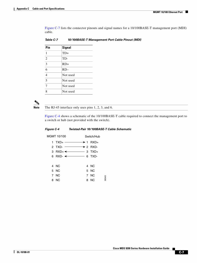
Appendix C Cable and Port Specifications MGMT 10/100 Ethernet Port
Figure C-7 lists the connector pinouts and signal names for a 10/100BASE-T management port (MDI) cable.
Note The RJ-45 interface only uses pins 1, 2, 3, and 6.
Figure C-4 shows a schematic of the 10/100BASE-T cable required to connect the management port to a switch or hub (not provided with the switch).
Figure C-4 Twisted-Pair 10/100BASE-T Cable Schematic
Table C-7 10/100BASE-T Management Port Cable Pinout (MDI)
Pin Signal
1 TD+
2 TD-
3 RD+
6 RD–
4 Not used
5 Not used
7 Not used
8 Not used
1 TXD+
2 TXD-
3 RXD+
6 RXD-
1 RXD+
MGMT 10/100 Switch/Hub
2 RXD-
3 TXD+
6 TXD-
4 NC
5 NC
7 NC
8 NC
4 NC
5 NC
7 NC
8 NC 9934
3
C-7Cisco MDS 9200 Series Hardware Installation Guide
OL-16188-01
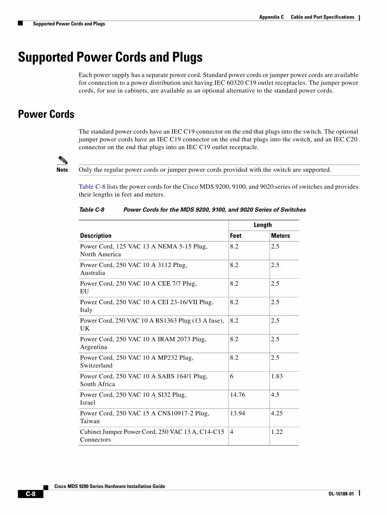
Appendix C Cable and Port Specifications Supported Power Cords and Plugs
Supported Power Cords and PlugsEach power supply has a separate power cord. Standard power cords or jumper power cords are available for connection to a power distribution unit having IEC 60320 C19 outlet receptacles. The jumper power cords, for use in cabinets, are available as an optional alternative to the standard power cords.
Power CordsThe standard power cords have an IEC C19 connector on the end that plugs into the switch. The optional jumper power cords have an IEC C19 connector on the end that plugs into the switch, and an IEC C20 connector on the end that plugs into an IEC C19 outlet receptacle.
Note Only the regular power cords or jumper power cords provided with the switch are supported.
Table C-8 lists the power cords for the Cisco MDS 9200, 9100, and 9020 series of switches and provides their lengths in feet and meters.
Table C-8 Power Cords for the MDS 9200, 9100, and 9020 Series of Switches
Description
Length
Feet Meters
Power Cord, 125 VAC 13 A NEMA 5-15 Plug, North America
8.2 2.5
Power Cord, 250 VAC 10 A 3112 Plug, Australia
8.2 2.5
Power Cord, 250 VAC 10 A CEE 7/7 Plug, EU
8.2 2.5
Power Cord, 250 VAC 10 A CEI 23-16/VII Plug, Italy
8.2 2.5
Power Cord, 250 VAC 10 A BS1363 Plug (13 A fuse), UK
8.2 2.5
Power Cord, 250 VAC 10 A IRAM 2073 Plug, Argentina
8.2 2.5
Power Cord, 250 VAC 10 A MP232 Plug, Switzerland
8.2 2.5
Power Cord, 250 VAC 10 A SABS 164/1 Plug, South Africa
6 1.83
Power Cord, 250 VAC 10 A SI32 Plug, Israel
14.76 4.5
Power Cord, 250 VAC 15 A CNS10917-2 Plug, Taiwan
13.94 4.25
Cabinet Jumper Power Cord, 250 VAC 13 A, C14-C15 Connectors
4 1.22
C-8Cisco MDS 9200 Series Hardware Installation Guide
OL-16188-01
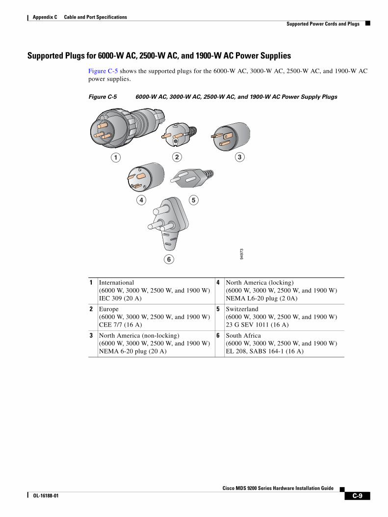
Appendix C Cable and Port Specifications Supported Power Cords and Plugs
Supported Plugs for 6000-W AC, 2500-W AC, and 1900-W AC Power Supplies
Figure C-5 shows the supported plugs for the 6000-W AC, 3000-W AC, 2500-W AC, and 1900-W AC
power supplies.
Figure C-5 6000-W AC, 3000-W AC, 2500-W AC, and 1900-W AC Power Supply Plugs
1 International (6000 W, 3000 W, 2500 W, and 1900 W) IEC 309 (20 A)
4 North America (locking)(6000 W, 3000 W, 2500 W, and 1900 W) NEMA L6-20 plug (2 0A)
2 Europe(6000 W, 3000 W, 2500 W, and 1900 W) CEE 7/7 (16 A)
5 Switzerland(6000 W, 3000 W, 2500 W, and 1900 W) 23 G SEV 1011 (16 A)
3 North America (non-locking)(6000 W, 3000 W, 2500 W, and 1900 W) NEMA 6-20 plug (20 A)
6 South Africa (6000 W, 3000 W, 2500 W, and 1900 W) EL 208, SABS 164-1 (16 A)
9497
3
1 2
4 5
3
6
C-9Cisco MDS 9200 Series Hardware Installation Guide
OL-16188-01

Appendix C Cable and Port Specifications Supported Power Cords and Plugs
Figure C-6 shows an additional plug that is supported for the 1900-W AC power supply only.
Figure C-6 Additional Power Supply Plug Supported for 1900-W Only
Figure C-7 shows an additional plug that is supported for the 3000-W and 2500-W power supply, using 110 VAC.
Note Using the plug in Figure C-7 at 110 VAC results in 1300 W available to the system.
Figure C-7 Additional Power Supply Plug Supported for 3000-W and 2500-W 110 VAC Only
1 United Kingdom BS89/13, BS 1363/A (13 A; replaceable fuse)
1131
47
1 NEMA 5-20P North American power cord product ID: CAB-7513AC 110 VAC (20 A)
1131
68
C-10Cisco MDS 9200 Series Hardware Installation Guide
OL-16188-01
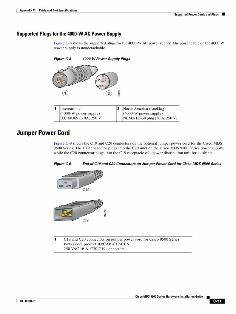
Appendix C Cable and Port Specifications Supported Power Cords and Plugs
Supported Plugs for the 4000-W AC Power Supply
Figure C-8 shows the supported plugs for the 4000-W AC power supply. The power cable on the 4000 W power supply is nondetachable.
Figure C-8 4000-W Power Supply Plugs
Jumper Power CordFigure C-9 shows the C19 and C20 connectors on the optional jumper power cord for the Cisco MDS 9500 Series. The C19 connector plugs into the C20 inlet on the Cisco MDS 9500 Series power supply, while the C20 connector plugs into the C19 receptacle of a power distribution unit for a cabinet.
Figure C-9 End of C19 and C20 Connectors on Jumper Power Cord for Cisco MDS 9500 Series
1 International (4000-W power supply) IEC 60309 (3 0A, 250 V)
2 North America (Locking)(4000-W power supply) NEMA L6-30 plug (30 A, 250 V)
9497
4
1 2
1 C19 and C20 connectors on jumper power cord for Cisco 9500 Series Power cord product ID:CAB-C19-CBN 250 VAC 16 A, C20-C19 connectors
1131
48
C20
C19
C-11Cisco MDS 9200 Series Hardware Installation Guide
OL-16188-01

Appendix C Cable and Port Specifications Supported Power Cords and Plugs
C-12Cisco MDS 9200 Series Hardware Installation Guide
OL-16188-01
Send documenta t ion comments to mds feedba ck -doc@c i sco .com
Cisco MOL-16188-01
A
P P E N D I X D Site Planning and Maintenance RecordsThis appendix includes the following records to use when installing the Cisco MDS 9200 Series:
• Site Preparation Checklist, page D-1
• Contact and Site Information, page D-3
• Chassis and Module Information, page D-4
Note For information about how to query the switch for configuration information, see the Cisco MDS 9000 Family Configuration Guide or the Cisco MDS 9000 Family Fabric Manager Configuration Guide.
Site Preparation ChecklistPlanning the location and layout of your equipment rack or wiring closet is essential for successful switch operation, ventilation, and accessibility. Table D-1 lists the site planning tasks that we recommend completing before installing the Cisco MDS 9200 Series.
Consider heat dissipation when sizing the air-conditioning requirements for an installation. See Table B-1 on page B-1 for the environmental requirements, and the “Weight of Modules” section on page B-3 for power and heat ratings.
D-1DS 9200 Series Hardware Installation Guide
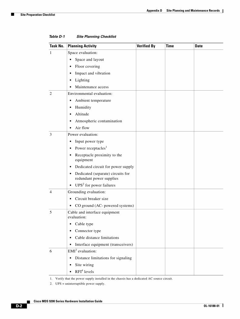
Appendix D Site Planning and Maintenance Records Site Preparation Checklist
Table D-1 Site Planning Checklist
Task No. Planning Activity Verified By Time Date
1 Space evaluation:
• Space and layout
• Floor covering
• Impact and vibration
• Lighting
• Maintenance access
2 Environmental evaluation:
• Ambient temperature
• Humidity
• Altitude
• Atmospheric contamination
• Air flow
3 Power evaluation:
• Input power type
• Power receptacles1
• Receptacle proximity to the equipment
• Dedicated circuit for power supply
• Dedicated (separate) circuits for redundant power supplies
• UPS2 for power failures
1. Verify that the power supply installed in the chassis has a dedicated AC source circuit.
2. UPS = uninterruptible power supply.
4 Grounding evaluation:
• Circuit breaker size
• CO ground (AC- powered systems)
5 Cable and interface equipment evaluation:
• Cable type
• Connector type
• Cable distance limitations
• Interface equipment (transceivers)
6 EMI3 evaluation:
• Distance limitations for signaling
• Site wiring
• RFI4 levels
D-2Cisco MDS 9200 Series Hardware Installation Guide
OL-16188-01
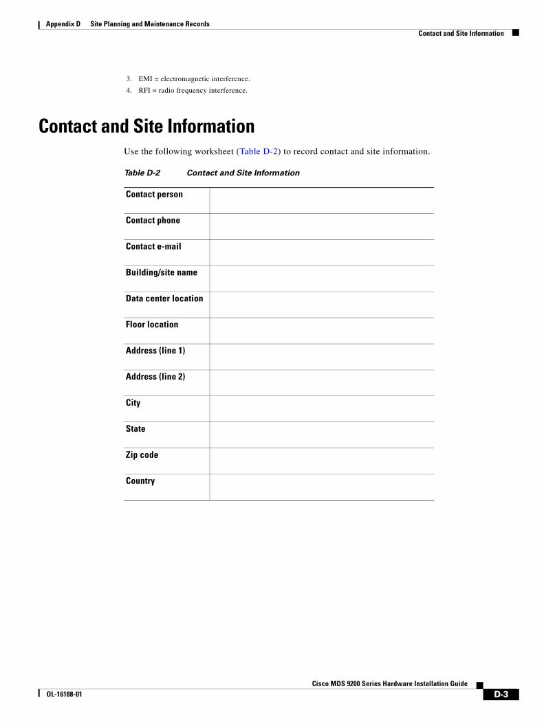
Appendix D Site Planning and Maintenance Records Contact and Site Information
Contact and Site InformationUse the following worksheet (Table D-2) to record contact and site information.
3. EMI = electromagnetic interference.
4. RFI = radio frequency interference.
Table D-2 Contact and Site Information
Contact person
Contact phone
Contact e-mail
Building/site name
Data center location
Floor location
Address (line 1)
Address (line 2)
City
State
Zip code
Country
D-3Cisco MDS 9200 Series Hardware Installation Guide
OL-16188-01
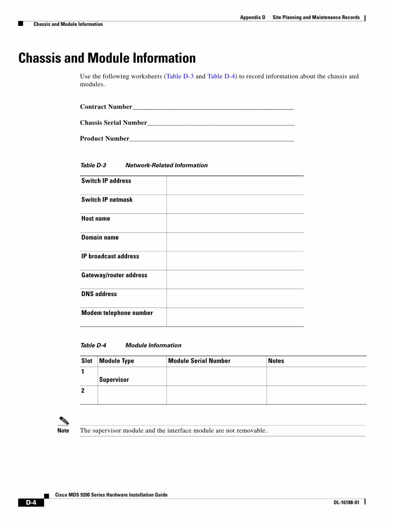
Appendix D Site Planning and Maintenance Records Chassis and Module Information
Chassis and Module InformationUse the following worksheets (Table D-3 and Table D-4) to record information about the chassis and modules.
Contract Number_______________________________________________
Chassis Serial Number___________________________________________
Product Number________________________________________________
Note The supervisor module and the interface module are not removable.
Table D-3 Network-Related Information
Switch IP address
Switch IP netmask
Host name
Domain name
IP broadcast address
Gateway/router address
DNS address
Modem telephone number
Table D-4 Module Information
Slot Module Type Module Serial Number Notes
1Supervisor
2
D-4Cisco MDS 9200 Series Hardware Installation Guide
OL-16188-01
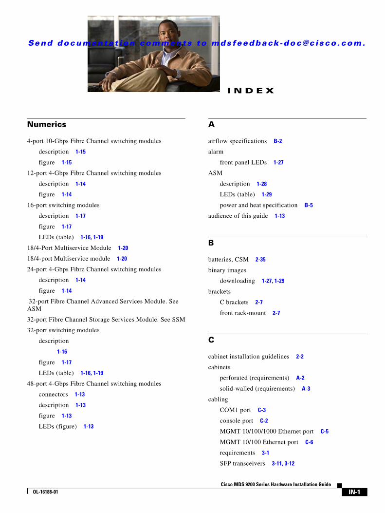
Send documenta t ion comments to mds feedback -doc@c i sco .com.
COL-16188-01
I N D E X
Numerics
4-port 10-Gbps Fibre Channel switching modules
description 1-15
figure 1-15
12-port 4-Gbps Fibre Channel switching modules
description 1-14
figure 1-14
16-port switching modules
description 1-17
figure 1-17
LEDs (table) 1-16, 1-19
18/4-Port Multiservice Module 1-20
18/4-port Multiservice module 1-20
24-port 4-Gbps Fibre Channel switching modules
description 1-14
figure 1-14
32-port Fibre Channel Advanced Services Module. See ASM
32-port Fibre Channel Storage Services Module. See SSM
32-port switching modules
description
1-16
figure 1-17
LEDs (table) 1-16, 1-19
48-port 4-Gbps Fibre Channel switching modules
connectors 1-13
description 1-13
figure 1-13
LEDs (figure) 1-13
A
airflow specifications B-2
alarm
front panel LEDs 1-27
ASM
description 1-28
LEDs (table) 1-29
power and heat specification B-5
audience of this guide 1-13
B
batteries, CSM 2-35
binary images
downloading 1-27, 1-29
brackets
C brackets 2-7
front rack-mount 2-7
C
cabinet installation guidelines 2-2
cabinets
perforated (requirements) A-2
solid-walled (requirements) A-3
cabling
COM1 port C-3
console port C-2
MGMT 10/100/1000 Ethernet port C-5
MGMT 10/100 Ethernet port C-6
requirements 3-1
SFP transceivers 3-11, 3-12
IN-1isco MDS 9200 Series Hardware Installation Guide

Index
Caching Services Module. See CSM
chassis
description 1-2
grounding 2-24
grounding (figure) 2-25
removing from rack (procedure) 2-40
Cisco MDS 9200 Series product overview 1-1
Cisco MDS 9222i Multiservice Modular Switch 1-1
clock modules
MTBF 1-10
replacing 1-10
COM1 port
cabling C-3
connecting (figure) 3-4
connecting (procedure) 3-4
pinouts (table) C-4
connecting
console port (figure) 3-2
console port (procedure) 3-2
Fibre Channel ports 3-5
MGMT 10/100 3-5
console port
cabling C-2
connecting (figure) 3-2
connecting (procedure) 3-3
pinouts C-2
contact and site information
records D-3
worksheet D-3
IN-2Cisco MDS 9200 Series Hardware Installation Guide
CSM
batteries 2-35
battery specifications (table) B-3
description 1-30
figure 1-30
installing (procedure) 2-33
internal view (figure) 1-30
LEDs (table) 1-32
maintaining 2-35
power and heat specification B-5
removing 2-31
CUP 1-20
CWDM transceivers
description 1-36
SFP transceiver specifications B-15
D
documentation
additional publications 1-15
downloading software images
ASM-SFN image 1-29
SSM 1-27
DWDM Fibre Channel SFP Transceivers 1-36
E
electrostatic discharge (ESD) 2-21
encryption 1-22
environmental specifications B-1
equipment required, installing 2-4
OL-16188-01
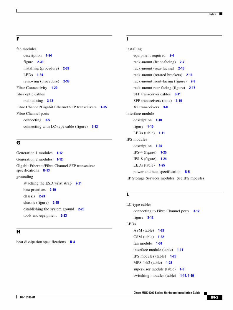
Index
F
fan modules
description 1-34
figure 2-39
installing (procedure) 2-39
LEDs 1-34
removing (procedure) 2-39
Fiber Connectivity 1-20
fiber optic cables
maintaining 3-13
Fibre Channel/Gigabit Ethernet SFP transceivers 1-35
Fibre Channel ports
connecting 3-5
connecting with LC-type cable (figure) 3-12
G
Generation 1 modules 1-12
Generation 2 modules 1-12
Gigabit Ethernet/Fibre Channel SFP transceiver specifications B-13
grounding
attaching the ESD wrist strap 2-21
best practices 2-19
chassis 2-24
chassis (figure) 2-25
establishing the system ground 2-23
tools and equipment 2-23
H
heat dissipation specifications B-4
OL-16188-01
I
installing
equipment required 2-4
rack-mount (front-facing) 2-7
rack-mount (rear-facing) 2-16
rack-mount (rotated brackets) 2-14
rack-mount front-facing (figure) 2-9
rack-mount rear-facing (figure) 2-17
SFP transceiver cables 3-11
SFP transceivers (note) 3-10
X2 transceivers 3-8
interface module
description 1-10
figure 1-10
LEDs (table) 1-11
IPS modules
description 1-24
IPS-4 (figure) 1-25
IPS-8 (figure) 1-24
LEDs (table) 1-25
power and heat specification B-5
IP Storage Services modules. See IPS modules
L
LC-type cables
connecting to Fibre Channel ports 3-12
figure 3-12
LEDs
ASM (table) 1-29
CSM (table) 1-32
fan module 1-34
interface module (table) 1-11
IPS modules (table) 1-25
MPS-14/2 (table) 1-23
supervisor module (table) 1-9
switching modules (table) 1-16, 1-19
IN-3Cisco MDS 9200 Series Hardware Installation Guide

Index
M
maintaining
fiber optic cables 3-13
SFP transceivers 3-13
maintenance records D-1
MGMT 10/100/1000 Ethernet port
cabling C-5
pinouts C-5
MGMT 10/100 Ethernet port
cabling C-6
connecting (figure) 3-5
connecting (procedure) 3-5
pinouts C-6
MPS-14/2
figure 1-23
LEDs (table) 1-23
N
network connections, preparing 3-2
new and changed information (table) 1-9
O
open racks, standard (requirements) A-3
P
physical specifications (table) B-2
pinouts
COM 1 port C-4
console port C-2
MGMT 10/100/1000 Ethernet port C-5
MGMT 10/100 Ethernet port C-6
plugs supported for power supplies C-8
IN-4Cisco MDS 9200 Series Hardware Installation Guide
ports
COM1 3-4
console 3-2
Fibre Channel 3-5
MGMT 10/100 3-5
potting 1-20
power cord, jumper C-12
power cords, length C-8
power-on
front panel LEDs 1-27
power supplies
description 1-33
figure 1-33
installing (procedure) 2-36
LED (table) 1-33
removing (procedure) 2-36
specifications B-4
supported plugs C-8
Preface 1-13
pre-installation
guidelines 2-2
options 2-2
required equipment 2-4
unpacking the switch 2-4
R
rack-mount installation
guidelines A-4
kit 2-5
procedures 2-5
specifications A-4
ready
front panel LEDs 1-27
records
chassis and module information D-4
contact and site information D-3
site planning and maintenance D-1
OL-16188-01

Index
removing
chassis from rack 2-40
SFP transceiver cables 3-12
SFP transceivers 3-10
X2 transceivers 3-8
S
self-test passed
front panel LEDs 1-27
self-test running
front panel LEDs 1-27
services modules
ASM 1-28
downloading binary image 1-29
installing (procedure) 2-33
IPS-4 1-24
IPS-8 1-24
MPS-14/2 1-22
MSFM-18/4 1-20
MSM-18/4 1-20
removing (procedure) 2-32
specifications B-2
SSM 1-26
OL-16188-01
SFP transceivers
cabling 3-11, 3-12
CWDM 1-36, B-15
description 1-35, 1-36, 3-8, B-9
Fibre Channel 1-35
Fibre Channel/Gigabit Ethernet 1-35
Fibre Channel/Gigabit Ethernet supported B-13
Fibre Channel specifications B-10
Fibre Channel supported B-10
Gigabit Ethernet 1-36
installing 3-9
installing a cable 3-11
latches supported 3-9
maintaining fiber optic cables 3-13
maintaining fiber optic cables (procedures) 3-13
removing 3-10
removing a cable (procedure) 3-12
specifications B-9
supported 1-34
shelf bracket
installation (four-post EIA rack) A-7
installation (telco/IEA) A-6
installing switch A-8
removing kit A-9
telco/EIA kit (note) A-4
site planning, preparation checklist D-1
software release requirement 1-2
specifications
airflow B-2
cables C-1
environmental B-1
heat dissipation B-4
modules B-2
physical B-2
pinouts C-1
power B-4
power requirements B-4
SFP transceivers B-9
IN-5Cisco MDS 9200 Series Hardware Installation Guide

Index
SSM
description 1-26
figure 1-26
starting up the switch 2-26
supervisor modules
Cisco MDS 9216A 1-7
Cisco MDS 9216i 1-7
installing 2-28
LEDs (table) 1-9
power and heat specification B-5
removing 2-31, 2-32
specifications B-2
switching modules
12-port 4-Gbps Fibre Channel switching modules 1-14
16-port 2-Gbps Fibre Channel (figure) 1-17
24-port 4-Gbps Fibre Channel switching modules 1-14
32-port 1-Gbps/2-Gbps Fibre Channel (figure) 1-17
48-port 4-Gbps Fibre Channel switching modules 1-13
4-port 10-Gbps Fibre Channel switching modules 1-15
description 1-12
downloading binary image 1-27
features 1-18
installing (procedure) 2-33
LEDs (table) 1-16, 1-19
positioning in chassis (figure) 2-30
power and heat specification B-5
removing 2-31, 2-32
removing (procedure) 2-32
specifications B-2
verifying installation 2-34
switch specifications (table) B-1
system grounding 2-19
IN-6Cisco MDS 9200 Series Hardware Installation Guide
T
Table B-1
telco racks (requirements) A-4
transceivers, supported SFPs. See SFP transceivers
W
weight of modules (table) B-3
X
X2 transceivers
description 1-35, B-6
figure 3-7
installing 3-8
removing 3-8
supported (table) B-7
OL-16188-01