Cisco CSR 1000V DRaaS Deploymentlisp.cisco.com/docs/cl2014us/CSR_DRaaS_Paper.pdfCisco Certified...
90
Cisco CSR 1000V DRaaS Deployment January 28, 2014
Transcript of Cisco CSR 1000V DRaaS Deploymentlisp.cisco.com/docs/cl2014us/CSR_DRaaS_Paper.pdfCisco Certified...
Cisco CSR 1000V DRaaS DeploymentJanuary 28, 2014
CCDE, CCENT, CCSI, Cisco Eos, Cisco Explorer, Cisco HealthPresence, Cisco IronPort, the Cisco logo, Cisco Nurse Connect, Cisco Pulse, Cisco SensorBase, Cisco StackPower, Cisco StadiumVision, Cisco TelePresence, Cisco TrustSec, Cisco Unified Computing System, Cisco WebEx, DCE, Flip Channels, Flip for Good, Flip Mino, Flipshare (Design), Flip Ultra, Flip Video, Flip Video (Design), Instant Broadband, and Welcome to the Human Network are trademarks; Changing the Way We Work, Live, Play, and Learn, Cisco Capital, Cisco Capital (Design), Cisco:Financed (Stylized), Cisco Store, Flip Gift Card, and One Million Acts of Green are service marks; and Access Registrar, Aironet, AllTouch, AsyncOS, Bringing the Meeting To You, Catalyst, CCDA, CCDP, CCIE, CCIP, CCNA, CCNP, CCSP, CCVP, Cisco, the Cisco Certified Internetwork Expert logo, Cisco IOS, Cisco Lumin, Cisco Nexus, Cisco Press, Cisco Systems, Cisco Systems Capital, the Cisco Systems logo, Cisco Unity, Collaboration Without Limitation, Continuum, EtherFast, EtherSwitch, Event Center, Explorer, Follow Me Browsing, GainMaker, iLYNX, IOS, iPhone, IronPort, the IronPort logo, Laser Link, LightStream, Linksys, MeetingPlace, MeetingPlace Chime Sound, MGX, Networkers, Networking Academy, PCNow, PIX, PowerKEY, PowerPanels, PowerTV, PowerTV (Design), PowerVu, Prisma, ProConnect, ROSA, SenderBase, SMARTnet, Spectrum Expert, StackWise, WebEx, and the WebEx logo are registered trademarks of Cisco and/or its affiliates in the United States and certain other countries.
All other trademarks mentioned in this document or website are the property of their respective owners. The use of the word partner does not imply a partnership relationship between Cisco and any other company. (1002R)
THE SOFTWARE LICENSE AND LIMITED WARRANTY FOR THE ACCOMPANYING PRODUCT ARE SET FORTH IN THE INFORMATION PACKET THAT SHIPPED WITH THE PRODUCT AND ARE INCORPORATED HEREIN BY THIS REFERENCE. IF YOU ARE UNABLE TO LOCATE THE SOFTWARE LICENSE OR LIMITED WARRANTY, CONTACT YOUR CISCO REPRESENTATIVE FOR A COPY.
The Cisco implementation of TCP header compression is an adaptation of a program developed by the University of California, Berkeley (UCB) as part of UCB’s public domain version of the UNIX operating system. All rights reserved. Copyright © 1981, Regents of the University of California.
NOTWITHSTANDING ANY OTHER WARRANTY HEREIN, ALL DOCUMENT FILES AND SOFTWARE OF THESE SUPPLIERS ARE PROVIDED “AS IS” WITH ALL FAULTS. CISCO AND THE ABOVE-NAMED SUPPLIERS DISCLAIM ALL WARRANTIES, EXPRESSED OR IMPLIED, INCLUDING, WITHOUT LIMITATION, THOSE OF MERCHANTABILITY, FITNESS FOR A PARTICULAR PURPOSE AND NONINFRINGEMENT OR ARISING FROM A COURSE OF DEALING, USAGE, OR TRADE PRACTICE.
IN NO EVENT SHALL CISCO OR ITS SUPPLIERS BE LIABLE FOR ANY INDIRECT, SPECIAL, CONSEQUENTIAL, OR INCIDENTAL DAMAGES, INCLUDING, WITHOUT LIMITATION, LOST PROFITS OR LOSS OR DAMAGE TO DATA ARISING OUT OF THE USE OR INABILITY TO USE THIS MANUAL, EVEN IF CISCO OR ITS SUPPLIERS HAVE BEEN ADVISED OF THE POSSIBILITY OF SUCH DAMAGES.
Cisco CSR 1000V DRaaS Deployment© 2014 Cisco Systems, Inc. All rights reserved.
C O N T E N T S
C H A P T E R 1 Introduction 1-1
Market Value 1-1
VMDC Virtual Services Architecture 1-1
C H A P T E R 2 Design Overview 2-1
CSR Role in DRaaS Architecture 2-2
Changes from VSA 1.0 2-2
CSR Interface Usage and Functionality 2-3
Data Center Interconnect Design Considerations 2-3
OTV Terminology 2-4
OTV Packet Flow 2-5
Network Encryption 2-6
C H A P T E R 3 OTV Deployment Considerations 3-1
High Availability (HA) 3-1
Virtual Extensible LAN (VXLAN) 3-1
Overlapping VLANs 3-2
Use of BDI as Default Gateway on CSR 1000V 3-2
OTV and MTUs 3-3
C H A P T E R 4 IP Mobility Design Considerations 4-1
LISP Overview 4-1
LISP Deployment Considerations 4-4
C H A P T E R 5 Deployment Details 5-1
Using OTV or LISP in DRaaS 5-1
OTV Implementation 5-2
LISP Implementation 5-14
LISP Infrastructure Components 5-14
xTR—ITR / ETR 5-14
PxTR—PITR / PETR 5-17
General Routing Policy 5-17
iCisco Cloud Services Router (CSR) 1000V DRaaS Deployment
Contents
Firewall Policy 5-18
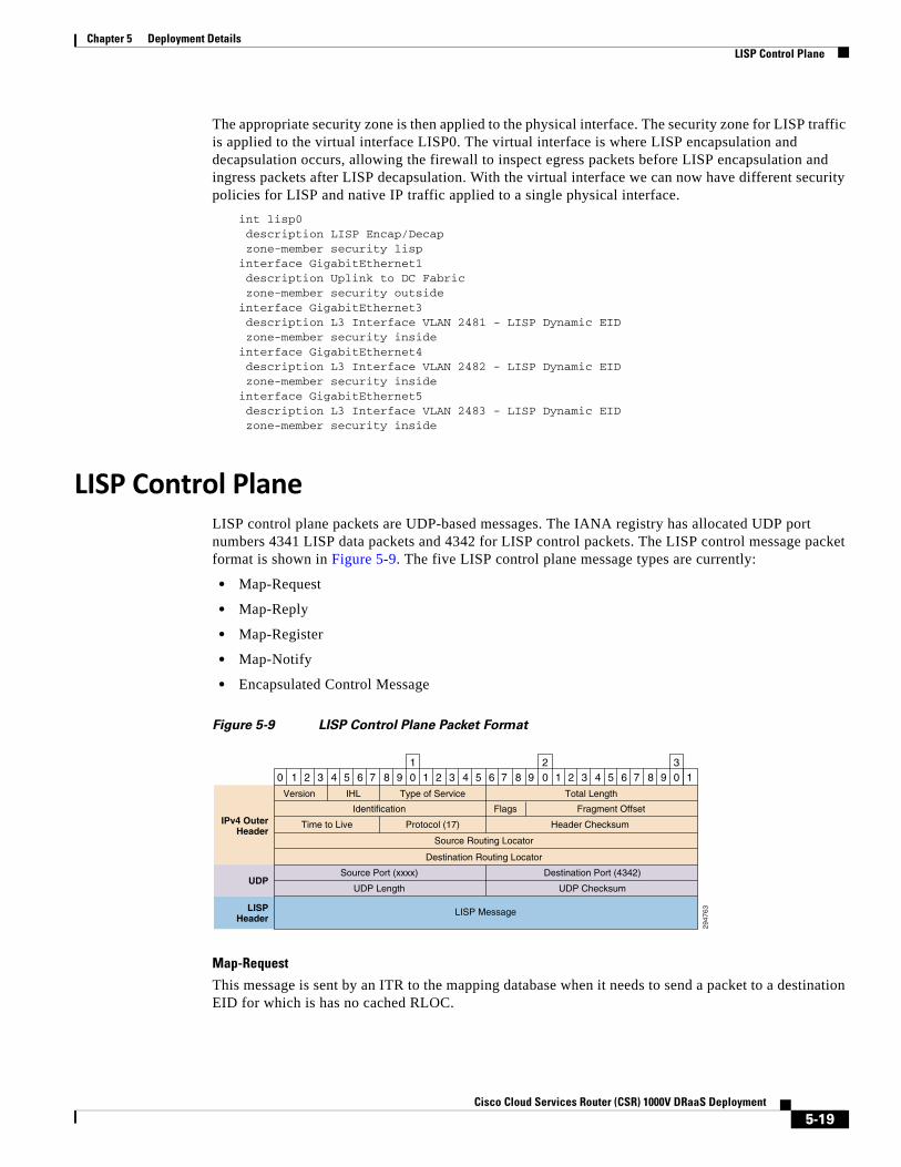
LISP Control Plane 5-19
LISP VM Mobility 5-21
LISP VM Mobility ESM Prerequisites 5-21
LISP Dynamic EID Detection 5-22
LISP Mobility Events 5-24
NON-LISP to EID Traffic Flow after a Mobility Event 5-25
EID to EID Intra-VLAN Traffic Flow after a Mobility Event 5-31
EID to EID Inter-VLAN Traffic Flow after a Mobility Event 5-32
A P P E N D I X A Best Practices/Caveats A-1
Key Findings A-1
OTV A-1
LISP A-2
Troubleshooting General Issues A-3
Network Connectivity A-3
OTV A-3
Packet Drops A-3
IPSec A-3
Commands A-4
Packet Capture A-4
LISP Commands A-5
Map Server A-5
PxTR A-6
A P P E N D I X B CSR Configurations B-1
Enterprise to Service Provider Configurations B-1
ENT-t19-CSR1 Configuration B-1
SP-t19-CSR1 Configuration B-6
vPC to vPC Configurations B-10
West-DC xTR Configuration B-10
East-DC xTR Configuration B-16
PxTR Configuration B-21
A P P E N D I X C Packaging C-1
iiCisco Cloud Services Router (CSR) 1000V DRaaS Deployment
Cisco Clo
C H A P T E R 1
IntroductionThis technical white paper provides a detailed technical solution description for Disaster Recovery as a Service (DRaaS) partial failover implementation.
The Cisco® DRaaS reference architecture is designed to provide a new set of cloud-based disaster-recovery capabilities, allowing Cisco-powered Cloud Providers to enhance their addressable market, financial performance, and differentiation compared to Commodity Service Providers.
Today, Service Providers (SPs) offering DRaaS do not typically provide support for partial failovers; instead, they require customers to make a binary decision to maintain operations at the primary site or failover the entire environment to the SP data center. This limitation frequently eliminates Cloud-based DRaaS offerings from consideration as a disaster recovery solution for many enterprises. Enterprises seek partial failover capabilities to reduce the outage and impact associated with executing their disaster recovery plan to address "contained" disasters such as corruption of a particular application due to virus or user errors.
This white paper describes a technical solution for SPs to support partial failover requirements using OTV and LISP technology in multi-tenant environments using Virtual Multiservices Data Center Virtual Services Architecture (VMDC VSA).
Market ValueDue to enterprise demand, many Cloud Service Providers are keen to provide partial failover capabilities to their end customers. This would allow some applications to stay running at the customer site during the disaster declaration and only failed applications would need to be recovered at the cloud recovery site. However, such a partial failover scenario can require complex engineering and result in unforeseen operational complexities. This paper provides a tested architecture to support partial failover in a multi-tenant environment and focuses on topologies that introduce the least operational complexity.
VMDC Virtual Services ArchitectureThe Cisco DRaaS reference architecture for cloud providers is built as an overlay on the Cisco VMDC reference architecture for Infrastructure as a Service (IaaS) and incorporates partner-based software solutions, providing continuous data protection (CDP) and host-based replication capabilities for storage-independent disaster recovery and business continuity. The solution architecture encompasses advanced capabilities such as encryption for integrated data security and data optimization to reduce WAN costs.
1-1ud Services Router (CSR) 1000V DRaaS Deployment
Chapter 1 Introduction VMDC Virtual Services Architecture
The VMDC VSA introduces virtualized Layer 4-7 services and new tenancy constructs to achieve much higher tenancy scale and reduced service orchestration complexity while eliminating cross-tenant dependencies for L4-L7 service allocation. Virtualized services include virtual routers, firewalls, load balancers, network analysis and WAN optimization virtual appliances. The DRaaS System partial failover scenario is accomplished by utilizing VMDC VSA architecture.
1-2Cisco Cloud Services Router (CSR) 1000V DRaaS Deployment

Cisco Clo
C H A P T E R 2
Design OverviewCisco's Disaster Recovery as a Service (DRaaS) architecture supports virtual data centers that consist of a collection of geographically-dispersed data center locations. Since data centers are distributed geographically, a combination of Layer 2 (L2) and Layer 3 (L3) connectivity is required to support different applications. The L2 Ethernet and L3 IP connectivity between data centers is addressed by a combination of next-generation Cisco Overlay Transport Virtualization (OTV) and Cisco Locator/ID Separation Protocol (LISP) technology, respectively. The DRaaS architecture is built over Virtual Multiservices Data Center (VMDC) 4.0 architecture (Figure 2-1).
Figure 2-1 DRaaS Architecture
WAN/PE
Nexus1000V
VSG
CustomerVRF
CSR1000V
CSR 1000VL3 Server VLAN Interface
OTV Join Interface
L3 Bridge Domain
OT
V
OTV
OT
V
OT
V
eBG
P
eBG
P
xTR
Compute
Service ProviderData Center-1
VM VM VM
L2/L3 Fabric
WAN/PE
Nexus1000V
VSG
CustomerVRF
CSR1000V
xTR
Compute
Service ProviderData Center-2
VM VM VM
L2/L3 Fabric
2945
93
Enterprise
L2/L3 Fabric
WAN/PE
VSG
Compute
CSR1000V
PxTR
VM VM VM
Nexus1000V
MPLSBackbone
CustomerVRF
eBGP
2-1ud Services Router (CSR) 1000V DRaaS Deployment
Chapter 2 Design Overview CSR Role in DRaaS Architecture
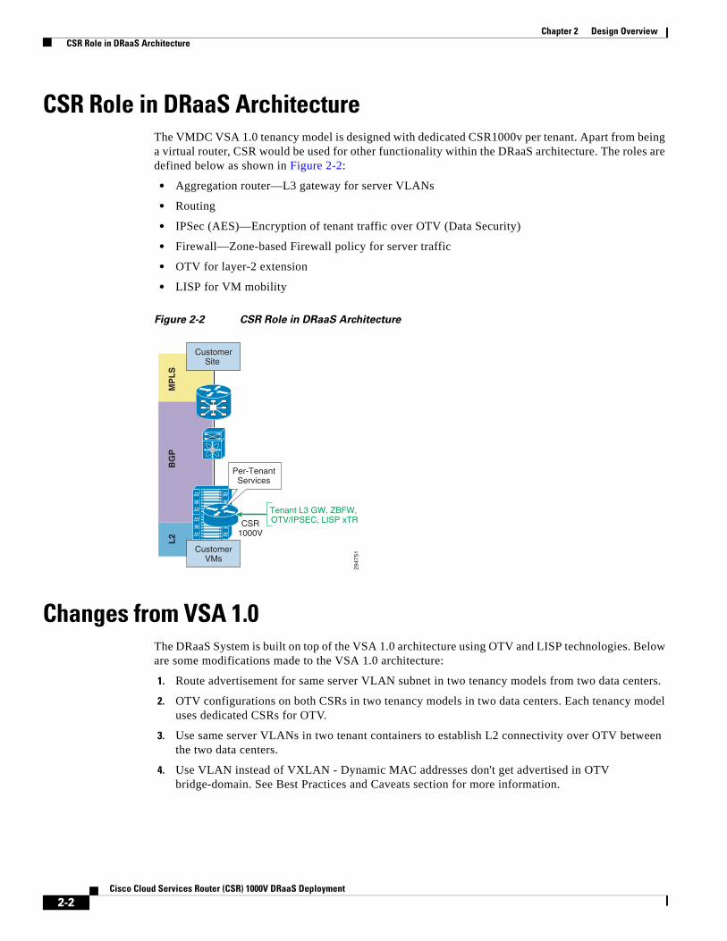
CSR Role in DRaaS ArchitectureThe VMDC VSA 1.0 tenancy model is designed with dedicated CSR1000v per tenant. Apart from being a virtual router, CSR would be used for other functionality within the DRaaS architecture. The roles are defined below as shown in Figure 2-2:
• Aggregation router—L3 gateway for server VLANs
• Routing
• IPSec (AES)—Encryption of tenant traffic over OTV (Data Security)
• Firewall—Zone-based Firewall policy for server traffic
• OTV for layer-2 extension
• LISP for VM mobility
Figure 2-2 CSR Role in DRaaS Architecture
Changes from VSA 1.0The DRaaS System is built on top of the VSA 1.0 architecture using OTV and LISP technologies. Below are some modifications made to the VSA 1.0 architecture:
1. Route advertisement for same server VLAN subnet in two tenancy models from two data centers.
2. OTV configurations on both CSRs in two tenancy models in two data centers. Each tenancy model uses dedicated CSRs for OTV.
3. Use same server VLANs in two tenant containers to establish L2 connectivity over OTV between the two data centers.
4. Use VLAN instead of VXLAN - Dynamic MAC addresses don't get advertised in OTV bridge-domain. See Best Practices and Caveats section for more information.
L2
BG
PM
PL
S
2947
51Customer
Site
CSR1000V
Per-TenantServices
CustomerVMs
Tenant L3 GW, ZBFW, OTV/IPSEC, LISP xTR
2-2Cisco Cloud Services Router (CSR) 1000V DRaaS Deployment
Chapter 2 Design Overview CSR Interface Usage and Functionality
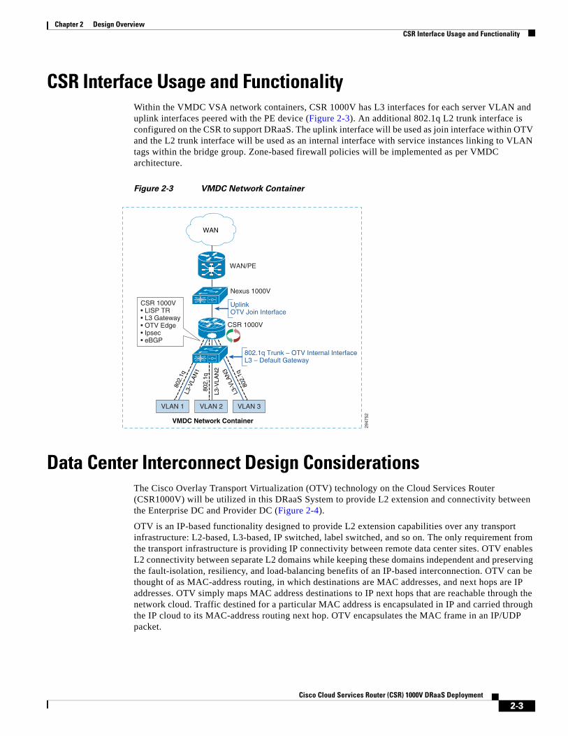
CSR Interface Usage and FunctionalityWithin the VMDC VSA network containers, CSR 1000V has L3 interfaces for each server VLAN and uplink interfaces peered with the PE device (Figure 2-3). An additional 802.1q L2 trunk interface is configured on the CSR to support DRaaS. The uplink interface will be used as join interface within OTV and the L2 trunk interface will be used as an internal interface with service instances linking to VLAN tags within the bridge group. Zone-based firewall policies will be implemented as per VMDC architecture.
Figure 2-3 VMDC Network Container
Data Center Interconnect Design ConsiderationsThe Cisco Overlay Transport Virtualization (OTV) technology on the Cloud Services Router (CSR1000V) will be utilized in this DRaaS System to provide L2 extension and connectivity between the Enterprise DC and Provider DC (Figure 2-4).
OTV is an IP-based functionality designed to provide L2 extension capabilities over any transport infrastructure: L2-based, L3-based, IP switched, label switched, and so on. The only requirement from the transport infrastructure is providing IP connectivity between remote data center sites. OTV enables L2 connectivity between separate L2 domains while keeping these domains independent and preserving the fault-isolation, resiliency, and load-balancing benefits of an IP-based interconnection. OTV can be thought of as MAC-address routing, in which destinations are MAC addresses, and next hops are IP addresses. OTV simply maps MAC address destinations to IP next hops that are reachable through the network cloud. Traffic destined for a particular MAC address is encapsulated in IP and carried through the IP cloud to its MAC-address routing next hop. OTV encapsulates the MAC frame in an IP/UDP packet.
VLAN 2 VLAN 3VLAN 1
802.
1q
802.
1q
L3-V
LAN
2
802.
1qL3
-VLA
N1
L3-V
LAN
3
2947
52
CSR 1000V
Nexus 1000V
WAN/PE
CSR 1000V• LISP TR• L3 Gateway• OTV Edge• Ipsec• eBGP
802.1q Trunk – OTV Internal InterfaceL3 – Default Gateway
UplinkOTV Join Interface
WAN
VMDC Network Container
2-3Cisco Cloud Services Router (CSR) 1000V DRaaS Deployment
Chapter 2 Design Overview OTV Terminology
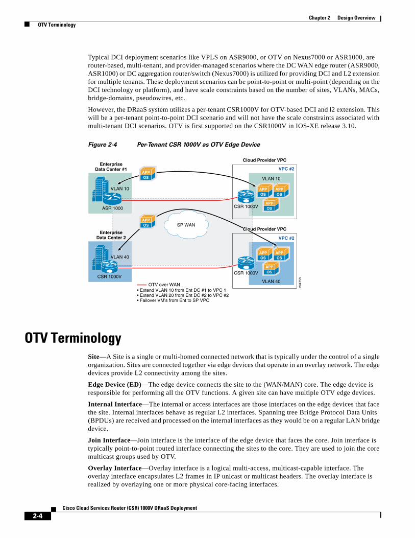
Typical DCI deployment scenarios like VPLS on ASR9000, or OTV on Nexus7000 or ASR1000, are router-based, multi-tenant, and provider-managed scenarios where the DC WAN edge router (ASR9000, ASR1000) or DC aggregation router/switch (Nexus7000) is utilized for providing DCI and L2 extension for multiple tenants. These deployment scenarios can be point-to-point or multi-point (depending on the DCI technology or platform), and have scale constraints based on the number of sites, VLANs, MACs, bridge-domains, pseudowires, etc.
However, the DRaaS system utilizes a per-tenant CSR1000V for OTV-based DCI and l2 extension. This will be a per-tenant point-to-point DCI scenario and will not have the scale constraints associated with multi-tenant DCI scenarios. OTV is first supported on the CSR1000V in IOS-XE release 3.10.
Figure 2-4 Per-Tenant CSR 1000V as OTV Edge Device
OTV TerminologySite—A Site is a single or multi-homed connected network that is typically under the control of a single organization. Sites are connected together via edge devices that operate in an overlay network. The edge devices provide L2 connectivity among the sites.
Edge Device (ED)—The edge device connects the site to the (WAN/MAN) core. The edge device is responsible for performing all the OTV functions. A given site can have multiple OTV edge devices.
Internal Interface—The internal or access interfaces are those interfaces on the edge devices that face the site. Internal interfaces behave as regular L2 interfaces. Spanning tree Bridge Protocol Data Units (BPDUs) are received and processed on the internal interfaces as they would be on a regular LAN bridge device.
Join Interface—Join interface is the interface of the edge device that faces the core. Join interface is typically point-to-point routed interface connecting the sites to the core. They are used to join the core multicast groups used by OTV.
Overlay Interface—Overlay interface is a logical multi-access, multicast-capable interface. The overlay interface encapsulates L2 frames in IP unicast or multicast headers. The overlay interface is realized by overlaying one or more physical core-facing interfaces.
2947
53
• Extend VLAN 10 from Ent DC #1 to VPC 1• Extend VLAN 20 from Ent DC #2 to VPC #2• Failover VM’s from Ent to SP VPC
ASR 1000
EnterpriseData Center #1
Cloud Provider VPC
VPC #2
VPC #2
VLAN 10
VLAN 10 APPOS
APPOS
APPOS
SP WAN
APPOS
APPOS
CSR 1000V
CSR 1000V
VLAN 40
APPOS
APPOS
APPOS
CSR 1000V
EnterpriseData Center 2
VLAN 40
Cloud Provider VPC
OTV over WAN
2-4Cisco Cloud Services Router (CSR) 1000V DRaaS Deployment

Chapter 2 Design Overview OTV Packet Flow
OTV Packet FlowWhen an ED receives a L2 frame on an internal interface, OTV performs the MAC table lookup based on the destination address of the L2 frame. If the frame is destined to a MAC address that is reachable through another internal interface, the frame is forwarded on that internal interface. OTV performs no other actions and the processing of the frame is complete.
If the frame is destined to a MAC address that was learned over an overlay interface, OTV performs the following tasks:
• Strips the preamble and frame check sequence (FCS) from the L2 frame.
• Adds an OTV header to the L2 frame and copies the 802.1Q information into the OTV header.
• Adds the IP address to the packet based on the initial MAC address table lookup. This IP address is used as the destination address for the IP packet that is sent into the core switch.
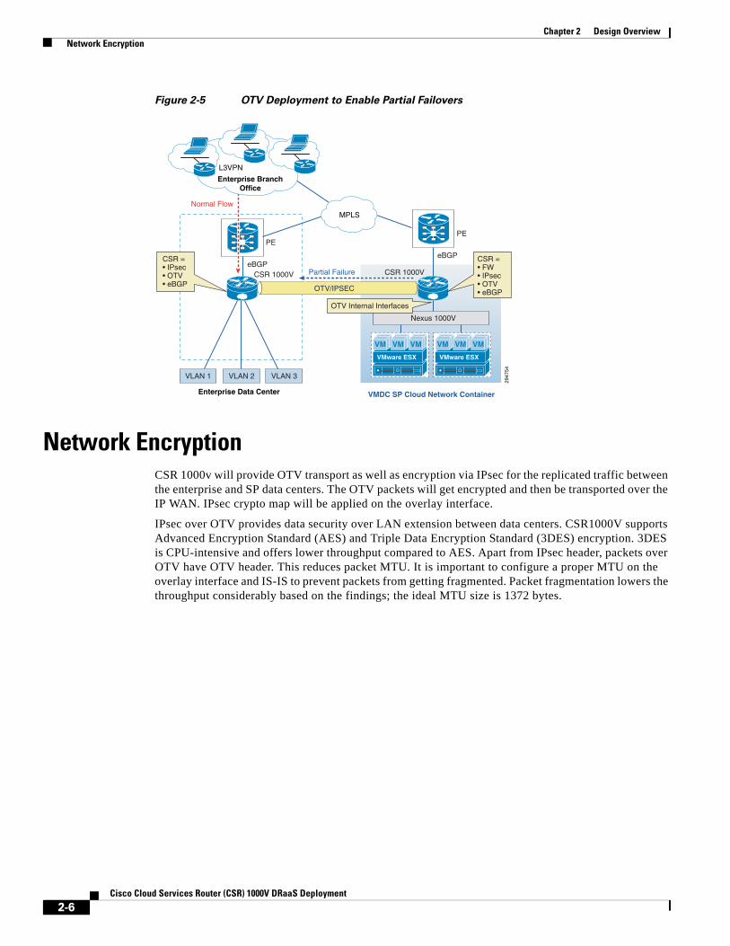
OTV traffic appears as IP traffic to the network core. At the destination site, the ED performs the reverse operation and presents the original L2 frame to the local site. The ED determines the correct internal interface to forward the frame on, based on the local MAC address table. Figure 2-5 shows the use of CSR/OTV to enable partial failovers between the enterprise and service provider (SP) data centers. CSR 1000V within the SP network container will be used as an OTV edge device. The traffic from the enterprise users always flows through the primary Enterprise data center during normal operations and during partial failover scenarios. The network services like firewall and load balancing will also be provided from the Enterprise data center during normal and partial failover scenarios. Only during full failover of the enterprise site in to the SP's VPC, will users be able access the recovery environment directly from the SP cloud and all the related network services will be provided from the SP cloud.
In this scenario, inter-VLAN routing for failed-over VMs in the provider cloud will happen locally in the Provider DC. Load balancing services for the failed-over VMs will be provided by the server load balancing (SLB) in the provider DC. The Zone-Based Firewall (ZBFW) residing on CSR 1000V in the Provider DC will provide FW services for the failed-over VMs. The VSG in the Provider DC will provide compute FW services for the migrated VMs.
In partial failover scenario, since there are dual gateways in each VLAN (Enterprise and SP Data Center), First Hop Redundancy Protocol (FHRP) filtering (HSRP localization) needs to be configured for egress path optimization. The replicated traffic between the enterprise and SP data centers will always flow through the OTV Tunnel. Also, the server-to-server communication in partial failover scenario will flow through the OTV Tunnel. All the east-west traffic flowing through the OTV will be encrypted via IPsec.
2-5Cisco Cloud Services Router (CSR) 1000V DRaaS Deployment
Chapter 2 Design Overview Network Encryption
Figure 2-5 OTV Deployment to Enable Partial Failovers
Network EncryptionCSR 1000v will provide OTV transport as well as encryption via IPsec for the replicated traffic between the enterprise and SP data centers. The OTV packets will get encrypted and then be transported over the IP WAN. IPsec crypto map will be applied on the overlay interface.
IPsec over OTV provides data security over LAN extension between data centers. CSR1000V supports Advanced Encryption Standard (AES) and Triple Data Encryption Standard (3DES) encryption. 3DES is CPU-intensive and offers lower throughput compared to AES. Apart from IPsec header, packets over OTV have OTV header. This reduces packet MTU. It is important to configure a proper MTU on the overlay interface and IS-IS to prevent packets from getting fragmented. Packet fragmentation lowers the throughput considerably based on the findings; the ideal MTU size is 1372 bytes.
VLAN 2 VLAN 3VLAN 1
VMware ESX
VM VM VM
VMware ESX
VM VM VM
Nexus 1000V
PE
eBGP
2947
54
OTV/IPSEC
Enterprise Data Center VMDC SP Cloud Network Container
PE
eBGPCSR 1000V CSR 1000VPartial Failure
Normal Flow
CSR = • FW • IPsec• OTV• eBGP
CSR = • IPsec• OTV• eBGP
OTV Internal Interfaces
MPLS
Enterprise BranchOffice
L3VPN
2-6Cisco Cloud Services Router (CSR) 1000V DRaaS Deployment

Cisco Clo
C H A P T E R 3
OTV Deployment ConsiderationsThe following OTV deployment topics are considered:
• High Availability (HA), page 3-1
• Virtual Extensible LAN (VXLAN), page 3-1
• Overlapping VLANs, page 3-2
• Use of BDI as Default Gateway on CSR 1000V, page 3-2
• OTV and MTUs , page 3-3
High Availability (HA)Recommended OTV Deployment should use a single CSR 1000V router at each site, utilizing the VMware HA mechanism for high availability. This will be acceptable for most customers and will prove more cost effective (half as many licenses required).
Virtual Extensible LAN (VXLAN)The DRaaS System will use traditional dot1q VLANs within the SP VPC instead of the VXLANs because of limitations with VXLAN unicast mode and MAC distribution (CSCuf60643). Dynamic MAC distribution is required for OTV and is not supported with VXLAN.
A VXLAN supports two different modes for flood traffic:
• Multicast Mode—A VXLAN uses an IP multicast network to send broadcast, multicast, and unknown unicast flood frames. Each multicast mode VXLAN has an assigned multicast group IP address. When a new VM joins a host in a multicast mode VXLAN, a Virtual Ethernet Module (VEM) joins the assigned multicast group IP address by sending IGMP join messages. Flood traffic, broadcast, multicast and unknown unicast from the VM is encapsulated and is sent using the assigned multicast group IP address as the destination IP address. Packets sent to known unicast MAC addresses are encapsulated and sent directly to the destination server VTEP IP addresses.
• Unicast-Only Mode—A VXLAN uses each VEM's single unicast IP address as the destination IP address to send broadcast, multicast, and unknown unicast flood frames of the designated VTEP on each VEM that has at least one VM in the corresponding VXLAN. When a new VM joins the host in a unicast-mode VXLAN, a designated VTEP is selected for receiving flood traffic on that host. This designated VTEP is communicated to all other hosts through the Virtual Supervisor Module (VSM). Flood traffic (broadcast, multicast, and unknown unicast) is replicated on each VEM's
3-1ud Services Router (CSR) 1000V DRaaS Deployment
Chapter 3 OTV Deployment Considerations Overlapping VLANs
designated VTEP in that VXLAN by encapsulating it with a VXLAN header. Packets are sent only to VEMs with a VM in that VXLAN. Packets that have a unicast MAC address are encapsulated and sent directly to the destination server's VTEP IP address.
• MAC Distribution Mode (supported only in unicast mode)—In this mode, unknown unicast flooding in the network is eliminated. The VSM learns all the MAC addresses from the VEMs in all the VXLANs and distributes those MAC addresses with VTEP IP mappings to other VEMs. Therefore, no unknown unicast MAC address exists in the network when the VMs on the VEMs are communicating and controlled by the same VSM.
Note MAC distribution works only for static MAC addresses. If dynamic MAC addresses are found on ports that use VXLANs that operate in MAC distribution mode, syslogs are generated to indicate that MAC distribution does not work with dynamic MAC addresses.
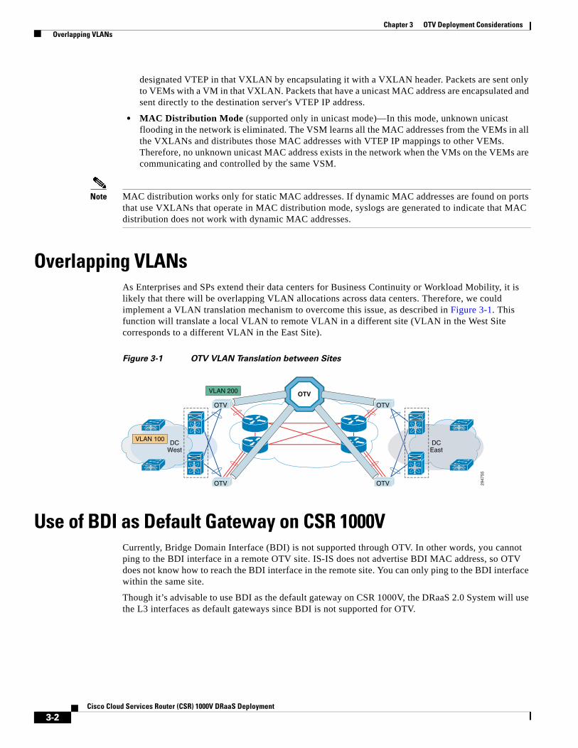
Overlapping VLANsAs Enterprises and SPs extend their data centers for Business Continuity or Workload Mobility, it is likely that there will be overlapping VLAN allocations across data centers. Therefore, we could implement a VLAN translation mechanism to overcome this issue, as described in Figure 3-1. This function will translate a local VLAN to remote VLAN in a different site (VLAN in the West Site corresponds to a different VLAN in the East Site).
Figure 3-1 OTV VLAN Translation between Sites
Use of BDI as Default Gateway on CSR 1000VCurrently, Bridge Domain Interface (BDI) is not supported through OTV. In other words, you cannot ping to the BDI interface in a remote OTV site. IS-IS does not advertise BDI MAC address, so OTV does not know how to reach the BDI interface in the remote site. You can only ping to the BDI interface within the same site.
Though it’s advisable to use BDI as the default gateway on CSR 1000V, the DRaaS 2.0 System will use the L3 interfaces as default gateways since BDI is not supported for OTV.
2947
55
DCWest
DCEast
OTV
OTV
OTV OTV
OTV
VLAN 100
VLAN 200
3-2Cisco Cloud Services Router (CSR) 1000V DRaaS Deployment

Chapter 3 OTV Deployment Considerations OTV and MTUs
OTV and MTUs OTV adds 42 bytes in the IP header packets, thus requiring a larger maximum transmission unit (MTU) for traffic to pass (Figure 3-2). Configure the join interface and all L3 interfaces that face the IP core between the OTV edge devices with the highest MTU size supported by the IP core. OTV sets the Don’t Fragment (DF) bit in the IP header for all OTV control and data packets so that the core cannot fragment these packets.
Figure 3-2 OTV UDP IPv4 Encapsulation
There are two ways to solve this problem:
1. Configure a larger MTU on all interfaces where traffic will be encapsulated, including the join interface and any links between the data centers that are in an OTV transport.
2. Lower the MTU on all servers so that the total packet size does not exceed the MTU of the interfaces where traffic is encapsulated.
2947
56
0 1
Version IHL Type of Service Total Length
Fragment OffsetFlagsIdentification
Time to Live
Source Port (xxxx) Destination Port (8472)
UDP LengthUDP
IPv4 OuterHeader
OTVHeader
UDP Checksum = 0
Protocol (17) Header Checksum
Source Site OTV Edge Device IP Address
Destination Site OTV Edge Device (or multicast) IP Address
12 3 4 5 6 7
R R R R R R
Frame in Ethernet or 802.1Q Format
Instance ID Reserved
Overlay IDR I
8 9 0 1 2 3 4 5 6 7 8 9 0 1 0 122
33
4 5 6 7 8 9
3-3Cisco Cloud Services Router (CSR) 1000V DRaaS Deployment
Chapter 3 OTV Deployment Considerations OTV and MTUs
3-4Cisco Cloud Services Router (CSR) 1000V DRaaS Deployment

Cisco Clo
C H A P T E R 4
IP Mobility Design ConsiderationsThe Cisco Locator/ID Separation Protocol Technology in extended subnet mode with OTV L2 extension on the Cloud Services Router (CSR1000V) will be utilized in this DRaaS 2.0 System. This provides IP Mobility between data centers within SP Cloud for the (VPC to VPC) In-Cloud replication use case.
The Cisco LISP Virtual Machine Mobility (LISP VM-Mobility) solution allows any host to move anywhere in the network while preserving its IP address. The capability allows members of a subnet to be dispersed across many locations without requiring any changes on the hosts and while maintaining optimal routing and scalability in the network. LISP is a network architecture and a set of protocols that implements a new semantic for IP addressing. LISP creates two namespaces and uses two IP addresses: Endpoint Identifiers (EIDs), which are assigned to end-hosts, and Routing Locators (RLOCs), which are assigned to devices (primarily routers) that make up the global routing system. Performing this separation offers several advantages, including:
• Improved routing system scalability by using topologically-aggregated RLOCs
• Provider-independence for devices numbered out of the EID space (IP portability)
• Low-OPEX multi-homing of end-sites with improved traffic engineering
• IPv6 transition functionality
• IP mobility (EIDs can move without changing - only the RLOC changes!)
LISP is a simple, incremental, network-based implementation that is deployed primarily in network edge devices. It requires no changes to host stacks, DNS, or local network infrastructure, and little to no major changes to existing network infrastructures.
LISP OverviewTo understand LISP, it is important to understand the concept of "Location to Identity Separation."
Figure 4-1 Mobility with Location/ID Protocol Technology
2947
57
x.y.z.1
a.b.c.1
Only the locationchanges
e.f.g.7
x.y.z.1
4-1ud Services Router (CSR) 1000V DRaaS Deployment

Chapter 4 IP Mobility Design Considerations LISP Overview
In traditional IP, the IP edge routing subnets are advertised all over the network using either an IGP or an EGP. Advertising any host address (subnet mask /32) occurs rarely; most of the time subnet larger or equal to /24 is used. Because all routes are advertised everywhere and installed in the forwarding plane in IP, limiting the amount of entries is important. By doing so, IP subnets are strictly limited to a geographical area and a subnet is only managed by one pair of router, which is the default gateway. This implies that if a node moves location, then its IP address must be updated accordingly to the local default gateway. This constraint is very strong and cumbersome; in order to escape from it, we see across sites more and more VLAN extension with all the drawbacks this approach can raise.
With LISP, such a constraint disappears; LISP splits the edge ID (EID) from the Routing Location (RLOC), allowing any host to move from location to location while keeping its identity.
LISP architecture is composed of several elements:
• ETR (Egress Tunnel Router)
– Registers the EID address space for which it has authority
– Identified by one (or more) RLOCs
– Receives and de-encapsulates the LISP frames
• Map Server
– The database where all EID/RLOC association are stored
– Can simply be deployed on a pair of devices for low scale implementation
– Or it can be a hierarchy of devices, organized like a DNS system for large scale implementation (LISP-DDT)
• ITR (Ingress Tunnel Router)
– Sends request toward the Map resolver
– Populates its local map-cache with the learned association
– Responsible for performing the LISP encapsulation
• Map Resolver
– Receives the request and selects the appropriate map server
• Proxy xTR
– The point of interconnection between an IP network and a LISP network, playing the role of ITR and ETR at this peering point.
An ETR is authoritative for a subnet, and registers it using a ‘map-register’ message to the map server. When triggered on the data-plane by a packet destined to a remote EID, the ITR performs a "map-request" toward the map-resolver, which forwards it to the right map-server, which then forwards it to the authoritative ETR. The ETR replies to the requesting ITR using a "map-reply" message. The map-reply message contains a list of the RLOCs having the capability to reach the requested EID along with their characteristic in terms of priority of usage and weighted load repartition.
Figure 4-2 shows LISP-ESM deployment using CSR 1000V with in VMDC VSA 1.0 architecture.
4-2Cisco Cloud Services Router (CSR) 1000V DRaaS Deployment

Chapter 4 IP Mobility Design Considerations LISP Overview
Figure 4-2 LISP within VMDC VSA 1.0 Architecture
LISP and OTV roles can be deployed in the network as shown in Figure 4-3. CSR 1000V within the VPC on source and destination data centers will be used as the OTV Edge device and LISP xTR. Mapping Server and Resolver will also reside on the CSR 1000V within the VPC at both the data centers in order to eliminate the use of additional devices and to reduce cost. This also improves scalability, as the MS/MR database will be per tenant. Figure 4-2 shows the options for PxTR deployment; the recommendation for PxTR deployment is on CSR1000V at the customer premise. Traffic to server VLANs, which are part of LISP domain, can be directed to the PxTR within the Enterprise.
VMware ESX
VM VM VM
VMware ESX
VM VM VM
Nexus 1000V
PE
eBGP
xTRxTR
2947
58
VMware ESX
VM VM VM
VMware ESX
VM VM VM
OTV/IPSEC
SP Cloud Data Center 1 SP Cloud Data Center 2
Enterprise Data Center
VMDC SP Cloud
Nexus 1000V
PE
eBGP
CSR = • default GW • ZBFW for all hosts• IPsec• LISP XTR & MS/MR
L3 for ZBFW
Non-LISP Sites
PxTR
MPLS
CSR 1000VCSR 1000V
4-3Cisco Cloud Services Router (CSR) 1000V DRaaS Deployment

Chapter 4 IP Mobility Design Considerations LISP Deployment Considerations
Figure 4-3 LISP & OTV Roles and Deployment in Network
LISP Deployment ConsiderationsAs an over-the-top technology, LISP has ingress (ITR) and egress (ETR) points. Everything that is in the core between these tunnel end points is overlaid transparently. The only strong requirement about this core is the ability to support greater PDU that includes the LISP header (Figure 4-4). The transport MTU should be 1536 to ensure transparency for 1500 bytes PDU. In case the core is not able to accommodate a larger frame than the basic ones, then LISP ITR is able to support the Path MTU Discovery (PMTUD) approach, sending the ICMP Destination Unreachable message (type 3, code 4) with a code meaning "fragmentation needed and DF set" back to the source of the packet as specified in the original IP header leading the source to adjust packet size to 1444. 1444 is the IP MTU of the original IP packet, but LISP also encapsulates the original IP header, so the payload of a LISP packet (before adding the external IP header) is: 1444 (original payload) + 20 (original Inner IP header) + 8 (LISP header) + 8 (UDP header) + 20 (Outer IP header) = 1500 bytes.
Enterprise Data Center
Non-LISP Sites
PxTR
VMware ESX
VM VM VM
VMware ESX
VM VM VM
Nexus 1000V
PE
eBGP
xTRxTR
2947
59
VMware ESX
VM VM VM
VMware ESX
VM VM VM
OTV/IPSEC/LISP
SP Cloud Data Center 1 SP Cloud Data Center 2
VMDC SP Cloud
Nexus 1000V
CSR 1000VCSR 1000V
PE
eBGP
LISP DC xTR: Aggregation routers@Data Center• SP-managed/owned• CSR 1000V vCE
OTV: Aggregationrouters @ VPC• SP-managed/owned
MPLS
PxTR: Border routers @ transit points• Customer backbone routers• Customer router @ co-location• SP-provided router/service (CSR 1000V)
Mapping Servers/Resolvers: Distributed across Data Centers• SP-managed/owned• SP provided service• CSR 1000v per VPC
4-4Cisco Cloud Services Router (CSR) 1000V DRaaS Deployment
Chapter 4 IP Mobility Design Considerations LISP Deployment Considerations
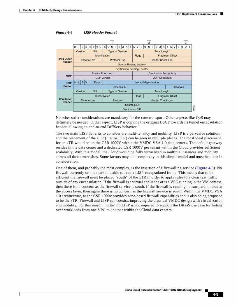
Figure 4-4 LISP Header Format
No other strict considerations are mandatory for the core transport. Other aspects like QoS may definitely be needed; in that aspect, LISP is copying the original DSCP towards its tunnel encapsulation header, allowing an end-to-end DiffServ behavior.
The two main LISP benefits to consider are multi-tenancy and mobility. LISP is a pervasive solution, and the placement of the xTR (ITR or ETR) can be seen in multiple places. The most ideal placement for an xTR would be on the CSR 1000V within the VMDC VSA 1.0 data centers. The default gateway resides in the data center and a dedicated CSR 1000V per tenant within the Cloud provides sufficient scalability. With this model, the Cloud would be fully virtualized in multiple instances and mobility across all data center sites. Some factors may add complexity to this simple model and must be taken in consideration.
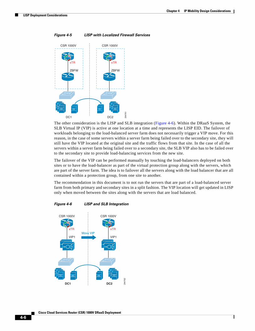
One of them, and probably the most complex, is the insertion of a firewalling service (Figure 4-5). No firewall currently on the market is able to read a LISP-encapsulated frame. This means that to be efficient the firewall must be placed "south" of the xTR in order to apply rules to a clear text traffic outside of any encapsulation. If the firewall is a virtual appliance or is a VSG running in the VM context, then there is no concern as the firewall service is south. If the firewall is running in transparent mode at the access layer, then again there is no concern as the firewall service is south. Within the VMDC VSA 1.0 architecture, as the CSR 1000v provides zone-based firewall capabilities and is also being proposed to be the xTR. Firewall and LISP can coexist, improving the classical VMDC design with virtualization and mobility. For this reason, multi-hop LISP is not required to support the DRaaS use case for failing over workloads from one VPC to another within the Cloud data centers.
2947
60
0 1
Version IHL Type of Service Total Length
Fragment OffsetFlagsIdentification
Time to Live
Source Port (xxxx) Destination Port (4341)
UDP LengthUDP
IPv4 OuterHeader
LISPHeader
UDP Checksum
Protocol (17) Header Checksum
Source Routing Locator
Destination Routing Locator
12 3 4 5 6 7
N L E Flags
Instance ID Reserved
Nonce/Map-VersionV I
8 9 0 1 2 3 4 5 6 7 8 9 0 1 0 122
33
4 5 6 7 8 9
Version IHL Type of Service Total Length
Fragment OffsetFlagsIdentification
Time to LiveIPv4 InnerHeader
Protocol Header Checksum
Source EID
Destination EID
4-5Cisco Cloud Services Router (CSR) 1000V DRaaS Deployment
Chapter 4 IP Mobility Design Considerations LISP Deployment Considerations
Figure 4-5 LISP with Localized Firewall Services
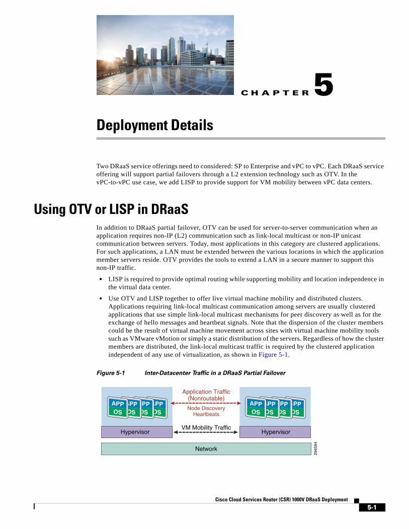
The other consideration is the LISP and SLB integration (Figure 4-6). Within the DRaaS System, the SLB Virtual IP (VIP) is active at one location at a time and represents the LISP EID. The failover of workloads belonging to the load-balanced server farm does not necessarily trigger a VIP move. For this reason, in the case of some servers within a server farm being failed over to the secondary site, they will still have the VIP located at the original site and the traffic flows from that site. In the case of all the servers within a server farm being failed over to a secondary site, the SLB VIP also has to be failed over to the secondary site to provide load-balancing services from the new site.
The failover of the VIP can be performed manually by touching the load-balancers deployed on both sites or to have the load-balancer as part of the virtual protection group along with the servers, which are part of the server farm. The idea is to failover all the servers along with the load balancer that are all contained within a protection group, from one site to another.
The recommendation in this document is to not run the servers that are part of a load-balanced server farm from both primary and secondary sites in a split fashion. The VIP location will get updated in LISP only when moved between the sites along with the servers that are load balanced.
Figure 4-6 LISP and SLB Integration
2947
61
xTR
ZBFW
DC1
CSR 1000V
DC2
CSR 1000V
xTR
ZBFW
2947
62
xTR
VIP1 VIP1
DC1
CSR 1000V
DC2
CSR 1000V
xTRMove VIP
4-6Cisco Cloud Services Router (CSR) 1000V DRaaS Deployment
Cisco Clo
C H A P T E R 5
Deployment DetailsTwo DRaaS service offerings need to considered: SP to Enterprise and vPC to vPC. Each DRaaS service offering will support partial failovers through a L2 extension technology such as OTV. In the vPC-to-vPC use case, we add LISP to provide support for VM mobility between vPC data centers.
Using OTV or LISP in DRaaSIn addition to DRaaS partial failover, OTV can be used for server-to-server communication when an application requires non-IP (L2) communication such as link-local multicast or non-IP unicast communication between servers. Today, most applications in this category are clustered applications. For such applications, a LAN must be extended between the various locations in which the application member servers reside. OTV provides the tools to extend a LAN in a secure manner to support this non-IP traffic.
• LISP is required to provide optimal routing while supporting mobility and location independence in the virtual data center.
• Use OTV and LISP together to offer live virtual machine mobility and distributed clusters. Applications requiring link-local multicast communication among servers are usually clustered applications that use simple link-local multicast mechanisms for peer discovery as well as for the exchange of hello messages and heartbeat signals. Note that the dispersion of the cluster members could be the result of virtual machine movement across sites with virtual machine mobility tools such as VMware vMotion or simply a static distribution of the servers. Regardless of how the cluster members are distributed, the link-local multicast traffic is required by the clustered application independent of any use of virtualization, as shown in Figure 5-1.
Figure 5-1 Inter-Datacenter Traffic in a DRaaS Partial Failover
2945
94
VM Mobility Traffic
Application Traffic(Nonroutable)
Node DiscoveryHeartbeats
Network
Hypervisor Hypervisor
5-1ud Services Router (CSR) 1000V DRaaS Deployment
Chapter 5 Deployment Details OTV Implementation
A DRaaS partial failover would result in some members of clusters being dispersed across multiple locations, so the LAN needs to be extended across these locations to support the forwarding of the non-IP traffic used for peer-discovery and heartbeats. OTV provides the necessary functions to extend a LAN across multiple sites and to support this non-IP communication between servers in the cluster.
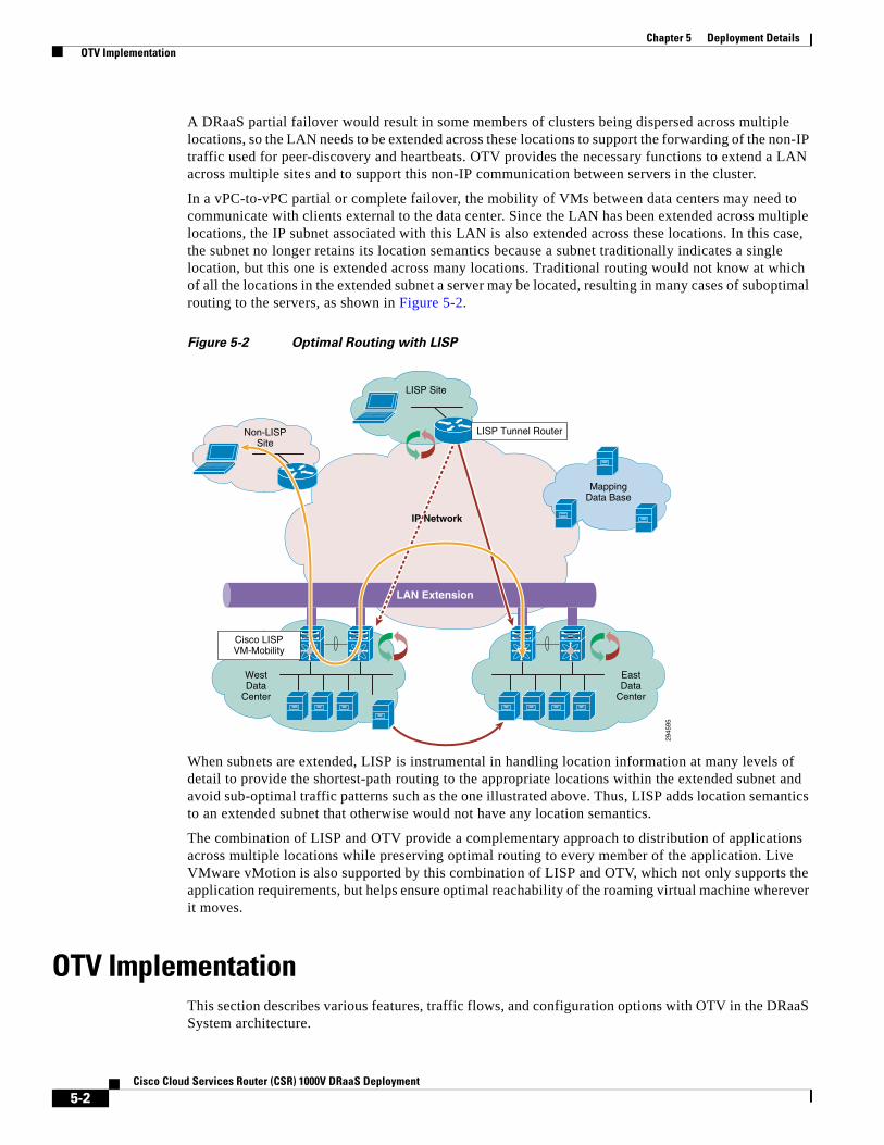
In a vPC-to-vPC partial or complete failover, the mobility of VMs between data centers may need to communicate with clients external to the data center. Since the LAN has been extended across multiple locations, the IP subnet associated with this LAN is also extended across these locations. In this case, the subnet no longer retains its location semantics because a subnet traditionally indicates a single location, but this one is extended across many locations. Traditional routing would not know at which of all the locations in the extended subnet a server may be located, resulting in many cases of suboptimal routing to the servers, as shown in Figure 5-2.
Figure 5-2 Optimal Routing with LISP
When subnets are extended, LISP is instrumental in handling location information at many levels of detail to provide the shortest-path routing to the appropriate locations within the extended subnet and avoid sub-optimal traffic patterns such as the one illustrated above. Thus, LISP adds location semantics to an extended subnet that otherwise would not have any location semantics.
The combination of LISP and OTV provide a complementary approach to distribution of applications across multiple locations while preserving optimal routing to every member of the application. Live VMware vMotion is also supported by this combination of LISP and OTV, which not only supports the application requirements, but helps ensure optimal reachability of the roaming virtual machine wherever it moves.
OTV ImplementationThis section describes various features, traffic flows, and configuration options with OTV in the DRaaS System architecture.
2945
95
MappingData Base
LISP Site
Non-LISPSite
LAN Extension
EastData
Center
WestData
Center
Cisco LISPVM-Mobility
LISP Tunnel Router
IP Network
5-2Cisco Cloud Services Router (CSR) 1000V DRaaS Deployment
Chapter 5 Deployment Details OTV Implementation
OTV Control Plane—The OTV can be implemented in unicast or multicast mode. The OTV control plane works generally the same way in both. The only difference is that in unicast mode each OTV device creates multiple copies of each control plane packet and unicast them to each remote OTV device part of the same logical overlay. The operational simplification brought by the unicast-only model is preferred in scenarios where LAN extension connectivity is required only between few (2-3) DC sites. See Appendix for unicast mode OTV configuration.
Interface Configuration—The interfaces can be configured in multiple ways on the CSR1000v. Use separate L3 interfaces for each VLAN. This limits the number of VLANs that can be used on CSR as version 3.10S supports ten vNICs (VMXNET3) per VM instance.
interface GigabitEthernet3 description VLAN 2121 Layer 3 Interface ip address 86.21.21.2 255.255.255.0 standby 0 ip 86.21.21.1 load-interval 30 negotiation auto lisp mobility vlan2121 lisp extended-subnet-mode arp timeout 1500
Single interface with L3 sub-interfaces for each VLAN. This option scales better with VLANs.
interface GigabitEthernet4 mtu 9000 no ip address negotiation auto!interface GigabitEthernet4.161 encapsulation dot1Q 161 ip address 192.168.11.4 255.255.255.0 no ip proxy-arp ip pim sparse-dense-mode standby version 2 standby 11 ip 192.168.11.1 lisp mobility lisp_esm11 lisp extended-subnet-mode
Use single L2 interface with BDI interfaces. This option is not currently supported on 3.10S.
The routed packets loop twice on CSR in first two options. The packets ingress on L3 interfaces, egress on routed L3 interface, ingress on L2 interface and then egress over the OTV. It didn’t seem to have any impact on throughput. For more details, see Inter and Intra VLAN traffic flow sections.
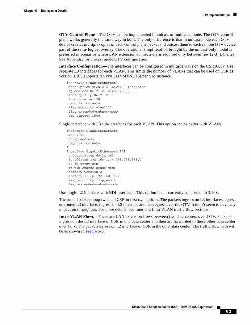
Intra-VLAN Flows—These are LAN extension flows between two data centers over OTV. Packets ingress on the L2 interface of CSR in one data center and then are forwarded to these other data center over OTV. The packets egress on L2 interface of CSR in the other data center. The traffic flow path will be as shown in Figure 5-3.
5-3Cisco Cloud Services Router (CSR) 1000V DRaaS Deployment
Chapter 5 Deployment Details OTV Implementation
Figure 5-3 Intra-VLAN Flows
The bridge table and mac entries for the given IP addressing in Figure 5-3 on two CSR would be as follows:
Enterprise CSRENT-t19-csr1#sh otv arp-nd-cache Overlay19 ARP/ND L3->L2 Address Mapping CacheBD MAC Layer-3 Address Age (HH:MM:SS) Local/Remote1921 0000.0261.2433 86.19.21.62 00:00:46 Remote1921 0050.568f.6324 86.19.21.254 00:00:43 Remote
ENT-t19-csr1#sh bridge-domain Bridge-domain 936 (1 ports in all)State: UP Mac learning: EnabledAging-Timer: 300 second(s) GigabitEthernet2 service instance 936 MAC address Policy Tag Age Pseudoport FFFF.FFFF.FFFF flood static 0 OLIST_PTR:0xe8ece400
Bridge-domain 1921 (2 ports in all)State: UP Mac learning: EnabledAging-Timer: 1800 second(s) GigabitEthernet2 service instance 1921 Overlay19 service instance 1921 MAC address Policy Tag Age Pseudoport 001B.24E0.5F4E forward static_r 0 OCE_PTR:0xea32dc00 0050.5687.1FB2 forward dynamic_c 1681 GigabitEthernet2.EFP1921 0050.568F.6324 forward static_r 0 OCE_PTR:0xea32dc00 0000.0260.D8D1 forward dynamic_c 1800 GigabitEthernet2.EFP1921 0000.0261.2433 forward static_r 0 OCE_PTR:0xea32dc00 FFFF.FFFF.FFFF flood static 0 OLIST_PTR:0xe8ece450
Bridge-domain 1922 (2 ports in all)
G4
G2
MPLS
DC FabricDC Fabric
2948
16
PE
CSR 1000V CSR 1000VENT SP
PE
VLAN 1921
IXIA
eBGP
OTV LAN Extension
eBGP
802.1q
86.19.21.1
86.19.22.1
86.19.21.254
86.19.22.254
86.19.21.52
86.19.22.52
86.19.21.62
G2G3
G1G1
G4
G3
G2
802.1q
VLAN 1921VLA
N 1
922
VLA
N 1
922
IXIA
86.19.22.62
IXIA
802.1qG2
5-4Cisco Cloud Services Router (CSR) 1000V DRaaS Deployment
Chapter 5 Deployment Details OTV Implementation
State: UP Mac learning: EnabledAging-Timer: 1800 second(s) GigabitEthernet2 service instance 1922 Overlay19 service instance 1922 MAC address Policy Tag Age Pseudoport FFFF.FFFF.FFFF flood static 0 OLIST_PTR:0xe8ece460 0050.5687.35F7 forward dynamic_c 1684 GigabitEthernet2.EFP1922
ENT-t19-csr1#sh ip arpProtocol Address Age (min) Hardware Addr Type InterfaceInternet 86.19.21.1 - 0050.5687.1fb2 ARPA GigabitEthernet7Internet 86.19.22.1 - 0050.5687.35f7 ARPA GigabitEthernet8Internet 86.19.23.1 - 0050.5687.438b ARPA GigabitEthernet9
ENT-t19-csr1#sh otv route
Codes: BD - Bridge-Domain, AD - Admin-Distance, SI - Service Instance, * - Backup Route
OTV Unicast MAC Routing Table for Overlay19
Inst VLAN BD MAC Address AD Owner Next Hops(s)---------------------------------------------------------- 0 1921 1921 0000.0260.d8d1 40 BD Eng Gi2:SI1921 0 1921 1921 0000.0261.2433 50 ISIS SP-t19-csr1 0 1921 1921 001b.24e0.5f4e 50 ISIS SP-t19-csr1 0 1921 1921 0023.8b03.759f 50 ISIS SP-t19-csr1 0 1921 1921 0050.5687.1fb2 40 BD Eng Gi2:SI1921 0 1921 1921 0050.568f.6324 50 ISIS SP-t19-csr1 0 1922 1922 0050.5687.35f7 40 BD Eng Gi2:SI19227 unicast routes displayed in Overlay19
----------------------------------------------------------7 Total Unicast Routes Displayed
Service Provider CSRSP-t19-csr1#sh otv arp-nd-cache Overlay19 ARP/ND L3->L2 Address Mapping CacheBD MAC Layer-3 Address Age (HH:MM:SS) Local/Remote1921 0000.0260.d8d1 86.19.21.52 00:00:55 Remote
SP-t19-csr1#sh bridge-domain Bridge-domain 936 (1 ports in all)State: UP Mac learning: EnabledAging-Timer: 300 second(s) GigabitEthernet2 service instance 936 MAC address Policy Tag Age Pseudoport FFFF.FFFF.FFFF flood static 0 OLIST_PTR:0xe8f20c00
Bridge-domain 1921 (2 ports in all)State: UP Mac learning: EnabledAging-Timer: 1800 second(s) GigabitEthernet2 service instance 1921 Overlay19 service instance 1921 MAC address Policy Tag Age Pseudoport 001B.24E0.5F4E forward dynamic_c 1708 GigabitEthernet2.EFP1921 0050.5687.1FB2 forward static_r 0 OCE_PTR:0xea175800 0023.8B03.759F forward dynamic_c 1708 GigabitEthernet2.EFP1921 0050.568F.6324 forward dynamic_c 1725 GigabitEthernet2.EFP1921 0000.0260.D8D1 forward static_r 0 OCE_PTR:0xea175800 0000.0261.2433 forward dynamic_c 1721 GigabitEthernet2.EFP1921 FFFF.FFFF.FFFF flood static 0 OLIST_PTR:0xe8f20c50
5-5Cisco Cloud Services Router (CSR) 1000V DRaaS Deployment
Chapter 5 Deployment Details OTV Implementation
Bridge-domain 1922 (2 ports in all)State: UP Mac learning: EnabledAging-Timer: 1800 second(s) GigabitEthernet2 service instance 1922 Overlay19 service instance 1922 MAC address Policy Tag Age Pseudoport FFFF.FFFF.FFFF flood static 0 OLIST_PTR:0xe8f20c60 0050.5687.35F7 forward static_r 0 OCE_PTR:0xea175820
SP-t19-csr1#sh ip arpProtocol Address Age (min) Hardware Addr Type InterfaceInternet 86.19.21.52 1 0000.0260.d8d1 ARPA GigabitEthernet9Internet 86.19.21.62 1 0000.0261.2433 ARPA GigabitEthernet9Internet 86.19.21.254 - 0050.568f.6324 ARPA GigabitEthernet9Internet 86.19.22.254 - 0050.568f.193c ARPA GigabitEthernet10Internet 86.19.23.254 - 0050.568f.2b13 ARPA GigabitEthernet11
SP-t19-csr1#sh otv route
Codes: BD - Bridge-Domain, AD - Admin-Distance, SI - Service Instance, * - Backup Route
OTV Unicast MAC Routing Table for Overlay19
Inst VLAN BD MAC Address AD Owner Next Hops(s)---------------------------------------------------------- 0 1921 1921 0000.0260.d8d1 50 ISIS ENT-t19-csr1 0 1921 1921 0000.0261.2433 40 BD Eng Gi2:SI1921 0 1921 1921 001b.24e0.5f4e 40 BD Eng Gi2:SI1921 0 1921 1921 0023.8b03.759f 40 BD Eng Gi2:SI1921 0 1921 1921 0050.5687.1fb2 50 ISIS ENT-t19-csr1 0 1921 1921 0050.568f.6324 40 BD Eng Gi2:SI1921 0 1922 1922 0050.5687.35f7 50 ISIS ENT-t19-csr1
7 unicast routes displayed in Overlay19
----------------------------------------------------------7 Total Unicast Routes Displayed
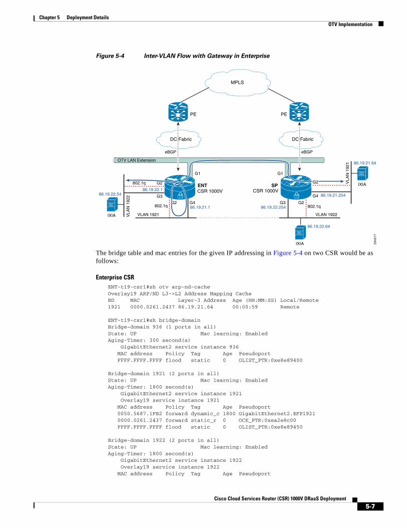
Inter-VLAN Flow with Gateway in Enterprise—These flows are routed flows over OTV. Two different traffic flow paths can exist depending on where the gateway is configured. If the gateway is Local CSR (Enterprise), then the packet will ingress on the L2 interface, egress on the routed L3 interface, ingress on the L2 interface and over OTV to the other data center and egress on the L2 interface. The traffic flow path will be as shown in Figure 5-4.
5-6Cisco Cloud Services Router (CSR) 1000V DRaaS Deployment
Chapter 5 Deployment Details OTV Implementation
Figure 5-4 Inter-VLAN Flow with Gateway in Enterprise
The bridge table and mac entries for the given IP addressing in Figure 5-4 on two CSR would be as follows:
Enterprise CSRENT-t19-csr1#sh otv arp-nd-cache Overlay19 ARP/ND L3->L2 Address Mapping CacheBD MAC Layer-3 Address Age (HH:MM:SS) Local/Remote1921 0000.0261.2437 86.19.21.64 00:00:59 Remote
ENT-t19-csr1#sh bridge-domain Bridge-domain 936 (1 ports in all)State: UP Mac learning: EnabledAging-Timer: 300 second(s) GigabitEthernet2 service instance 936 MAC address Policy Tag Age Pseudoport FFFF.FFFF.FFFF flood static 0 OLIST_PTR:0xe8e89400
Bridge-domain 1921 (2 ports in all)State: UP Mac learning: EnabledAging-Timer: 1800 second(s) GigabitEthernet2 service instance 1921 Overlay19 service instance 1921 MAC address Policy Tag Age Pseudoport 0050.5687.1FB2 forward dynamic_c 1800 GigabitEthernet2.EFP1921 0000.0261.2437 forward static_r 0 OCE_PTR:0xea2e8c00 FFFF.FFFF.FFFF flood static 0 OLIST_PTR:0xe8e89450
Bridge-domain 1922 (2 ports in all)State: UP Mac learning: EnabledAging-Timer: 1800 second(s) GigabitEthernet2 service instance 1922 Overlay19 service instance 1922 MAC address Policy Tag Age Pseudoport
G4
MPLS
DC FabricDC Fabric
2948
17
PE
CSR 1000V CSR 1000VENT SP
PE
VLAN 1922
IXIA
eBGP
OTV LAN Extension
eBGP
802.1q
86.19.21.1
86.19.22.1
86.19.22.254
86.19.21.25486.19.22.54
86.19.22.64
G2G3
G1G1
G4
G3
G2
802.1q
VLAN 1921VLA
N 1
922
VLA
N 1
921
IXIA
86.19.21.64
IXIA
802.1qG2
G2
5-7Cisco Cloud Services Router (CSR) 1000V DRaaS Deployment
Chapter 5 Deployment Details OTV Implementation
FFFF.FFFF.FFFF flood static 0 OLIST_PTR:0xe8e89460 0000.0159.79B0 forward dynamic_c 1722 GigabitEthernet2.EFP1922 0050.5687.35F7 forward dynamic_c 1636 GigabitEthernet2.EFP1922
ENT-t19-csr1#sh ip arpProtocol Address Age (min) Hardware Addr Type InterfaceInternet 86.19.21.1 - 0050.5687.1fb2 ARPA GigabitEthernet7Internet 86.19.21.64 1 0000.0261.2437 ARPA GigabitEthernet7Internet 86.19.22.1 - 0050.5687.35f7 ARPA GigabitEthernet8Internet 86.19.22.54 1 0000.0159.79b0 ARPA GigabitEthernet8Internet 86.19.23.1 - 0050.5687.438b ARPA GigabitEthernet9
ENT-t19-csr1#sh otv route
Codes: BD - Bridge-Domain, AD - Admin-Distance, SI - Service Instance, * - Backup Route
OTV Unicast MAC Routing Table for Overlay19
Inst VLAN BD MAC Address AD Owner Next Hops(s)---------------------------------------------------------- 0 1921 1921 0000.0261.2437 50 ISIS SP-t19-csr1 0 1921 1921 0050.5687.1fb2 40 BD Eng Gi2:SI1921 0 1922 1922 0000.0159.79b0 40 BD Eng Gi2:SI1922 0 1922 1922 0050.5687.35f7 40 BD Eng Gi2:SI1922
4 unicast routes displayed in Overlay19
----------------------------------------------------------4 Total Unicast Routes Displayed
Service Provider CSRSP-t19-csr1#sh otv arp-nd-cache Overlay19 ARP/ND L3->L2 Address Mapping CacheBD MAC Layer-3 Address Age (HH:MM:SS) Local/Remote1921 0050.5687.1fb2 86.19.21.1 00:00:30 Remote1922 0000.0159.79b0 86.19.22.54 00:00:33 Remote
SP-t19-csr1#sh bridge-domSP-t19-csr1#sh bridge-domain Bridge-domain 936 (1 ports in all)State: UP Mac learning: EnabledAging-Timer: 300 second(s) GigabitEthernet2 service instance 936 MAC address Policy Tag Age Pseudoport FFFF.FFFF.FFFF flood static 0 OLIST_PTR:0xe8f0f400
Bridge-domain 1921 (2 ports in all)State: UP Mac learning: EnabledAging-Timer: 1800 second(s) GigabitEthernet2 service instance 1921 Overlay19 service instance 1921 MAC address Policy Tag Age Pseudoport 0050.5687.1FB2 forward static_r 0 OCE_PTR:0xea36ec00 0000.0261.2437 forward dynamic_c 1756 GigabitEthernet2.EFP1921 FFFF.FFFF.FFFF flood static 0 OLIST_PTR:0xe8f0f450
Bridge-domain 1922 (2 ports in all)State: UP Mac learning: EnabledAging-Timer: 1800 second(s) GigabitEthernet2 service instance 1922 Overlay19 service instance 1922
5-8Cisco Cloud Services Router (CSR) 1000V DRaaS Deployment

Chapter 5 Deployment Details OTV Implementation
MAC address Policy Tag Age Pseudoport FFFF.FFFF.FFFF flood static 0 OLIST_PTR:0xe8f0f460 0000.0159.79B0 forward static_r 0 OCE_PTR:0xea36ec20 0050.5687.35F7 forward static_r 0 OCE_PTR:0xea36ec20
SP-t19-csr1# sh ip arpProtocol Address Age (min) Hardware Addr Type InterfaceInternet 86.19.21.254 - 0050.568f.6324 ARPA GigabitEthernet9Internet 86.19.22.254 - 0050.568f.193c ARPA GigabitEthernet10Internet 86.19.23.254 - 0050.568f.2b13 ARPA GigabitEthernet11
SP-t19-csr1#sh otv route
Codes: BD - Bridge-Domain, AD - Admin-Distance, SI - Service Instance, * - Backup Route
OTV Unicast MAC Routing Table for Overlay19
Inst VLAN BD MAC Address AD Owner Next Hops(s)---------------------------------------------------------- 0 1921 1921 0000.0261.2437 40 BD Eng Gi2:SI1921 0 1921 1921 0050.5687.1fb2 50 ISIS ENT-t19-csr1 0 1922 1922 0000.0159.79b0 50 ISIS ENT-t19-csr1 0 1922 1922 0050.5687.35f7 50 ISIS ENT-t19-csr1 0 1923 1923 0050.5687.438b 50 ISIS ENT-t19-csr1
5 unicast routes displayed in Overlay19
----------------------------------------------------------5 Total Unicast Routes Displayed
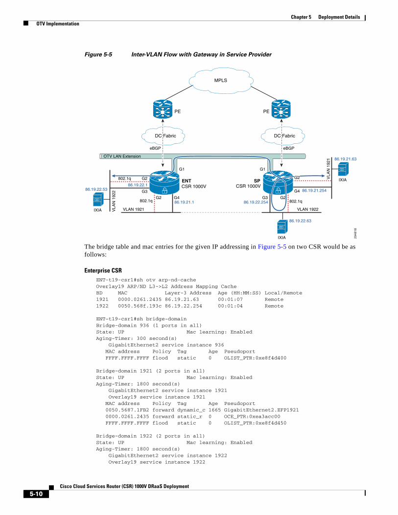
Inter-VLAN Flow with Gateway in Service Provider—The flow changes slightly if the gateway is on the remote CSR (Service Provider). In that case, the packet ingress on the L2 interface goes over OTV to the other data center, egresses on L2 interface on CSR, ingresses on L3 interface, and egresses on routed L3 interface. The traffic flow path will be as shown in Figure 5-5.
5-9Cisco Cloud Services Router (CSR) 1000V DRaaS Deployment
Chapter 5 Deployment Details OTV Implementation
Figure 5-5 Inter-VLAN Flow with Gateway in Service Provider
The bridge table and mac entries for the given IP addressing in Figure 5-5 on two CSR would be as follows:
Enterprise CSRENT-t19-csr1#sh otv arp-nd-cache Overlay19 ARP/ND L3->L2 Address Mapping CacheBD MAC Layer-3 Address Age (HH:MM:SS) Local/Remote1921 0000.0261.2435 86.19.21.63 00:01:07 Remote1922 0050.568f.193c 86.19.22.254 00:01:04 Remote
ENT-t19-csr1#sh bridge-domain Bridge-domain 936 (1 ports in all)State: UP Mac learning: EnabledAging-Timer: 300 second(s) GigabitEthernet2 service instance 936 MAC address Policy Tag Age Pseudoport FFFF.FFFF.FFFF flood static 0 OLIST_PTR:0xe8f4d400
Bridge-domain 1921 (2 ports in all)State: UP Mac learning: EnabledAging-Timer: 1800 second(s) GigabitEthernet2 service instance 1921 Overlay19 service instance 1921 MAC address Policy Tag Age Pseudoport 0050.5687.1FB2 forward dynamic_c 1665 GigabitEthernet2.EFP1921 0000.0261.2435 forward static_r 0 OCE_PTR:0xea3acc00 FFFF.FFFF.FFFF flood static 0 OLIST_PTR:0xe8f4d450
Bridge-domain 1922 (2 ports in all)State: UP Mac learning: EnabledAging-Timer: 1800 second(s) GigabitEthernet2 service instance 1922 Overlay19 service instance 1922
G4
MPLS
DC FabricDC Fabric
2948
18
PE
CSR 1000V CSR 1000VENT SP
PE
VLAN 1922
IXIA
eBGP
OTV LAN Extension
eBGP
802.1q
86.19.21.1
86.19.22.1
86.19.22.254
86.19.21.25486.19.22.53
86.19.22.63
G2G3
G1G1
G4
G3
G2
802.1q
VLAN 1921VLA
N 1
922
VLA
N 1
921
IXIA
86.19.21.63
IXIA
802.1qG2
G2
5-10Cisco Cloud Services Router (CSR) 1000V DRaaS Deployment
Chapter 5 Deployment Details OTV Implementation
MAC address Policy Tag Age Pseudoport FFFF.FFFF.FFFF flood static 0 OLIST_PTR:0xe8f4d460 0000.0159.79AE forward dynamic_c 1800 GigabitEthernet2.EFP1922 0050.5687.35F7 forward dynamic_c 1668 GigabitEthernet2.EFP1922 0050.568F.193C forward static_r 0 OCE_PTR:0xea3acc20
ENT-t19-csr1#sh ip arpProtocol Address Age (min) Hardware Addr Type InterfaceInternet 86.19.21.1 - 0050.5687.1fb2 ARPA GigabitEthernet7Internet 86.19.22.1 - 0050.5687.35f7 ARPA GigabitEthernet8Internet 86.19.23.1 - 0050.5687.438b ARPA GigabitEthernet9
ENT-t19-csr1#sh otv route
Codes: BD - Bridge-Domain, AD - Admin-Distance, SI - Service Instance, * - Backup Route
OTV Unicast MAC Routing Table for Overlay19
Inst VLAN BD MAC Address AD Owner Next Hops(s)---------------------------------------------------------- 0 1921 1921 0000.0261.2435 50 ISIS SP-t19-csr1 0 1921 1921 0050.5687.1fb2 40 BD Eng Gi2:SI1921 0 1922 1922 0000.0159.79ae 40 BD Eng Gi2:SI1922 0 1922 1922 0050.5687.35f7 40 BD Eng Gi2:SI1922 0 1922 1922 0050.568f.193c 50 ISIS SP-t19-csr1
5 unicast routes displayed in Overlay19
----------------------------------------------------------5 Total Unicast Routes Displayed
Service Provider CSRSP-t19-csr1#sh otv arp-nd-cache Overlay19 ARP/ND L3->L2 Address Mapping CacheBD MAC Layer-3 Address Age (HH:MM:SS) Local/Remote1922 0000.0159.79ae 86.19.22.53 00:01:46 Remote
SP-t19-csr1#sh bridge-domain Bridge-domain 936 (1 ports in all)State: UP Mac learning: EnabledAging-Timer: 300 second(s) GigabitEthernet2 service instance 936 MAC address Policy Tag Age Pseudoport FFFF.FFFF.FFFF flood static 0 OLIST_PTR:0xe8e87000
Bridge-domain 1921 (2 ports in all)State: UP Mac learning: EnabledAging-Timer: 1800 second(s) GigabitEthernet2 service instance 1921 Overlay19 service instance 1921 MAC address Policy Tag Age Pseudoport 0050.5687.1FB2 forward static_r 0 OCE_PTR:0xea32c000 0000.0261.2435 forward dynamic_c 1681 GigabitEthernet2.EFP1921 FFFF.FFFF.FFFF flood static 0 OLIST_PTR:0xe8e87050
Bridge-domain 1922 (2 ports in all)State: UP Mac learning: EnabledAging-Timer: 1800 second(s) GigabitEthernet2 service instance 1922 Overlay19 service instance 1922
5-11Cisco Cloud Services Router (CSR) 1000V DRaaS Deployment
Chapter 5 Deployment Details OTV Implementation
MAC address Policy Tag Age Pseudoport FFFF.FFFF.FFFF flood static 0 OLIST_PTR:0xe8e87060 0000.0159.79AE forward static_r 0 OCE_PTR:0xea32c020 0050.5687.35F7 forward static_r 0 OCE_PTR:0xea32c020 0050.568F.193C forward dynamic_c 1683 GigabitEthernet2.EFP1922
SP-t19-csr1#sh ip arpProtocol Address Age (min) Hardware Addr Type InterfaceInternet 86.19.21.63 2 0000.0261.2435 ARPA GigabitEthernet9Internet 86.19.21.254 - 0050.568f.6324 ARPA GigabitEthernet9Internet 86.19.22.53 2 0000.0159.79ae ARPA GigabitEthernet10Internet 86.19.22.254 - 0050.568f.193c ARPA GigabitEthernet10Internet 86.19.23.254 - 0050.568f.2b13 ARPA GigabitEthernet11
SP-t19-csr1#sh otv route
Codes: BD - Bridge-Domain, AD - Admin-Distance, SI - Service Instance, * - Backup Route
OTV Unicast MAC Routing Table for Overlay19
Inst VLAN BD MAC Address AD Owner Next Hops(s)---------------------------------------------------------- 0 1921 1921 0000.0261.2435 40 BD Eng Gi2:SI1921 0 1921 1921 0050.5687.1fb2 50 ISIS ENT-t19-csr1 0 1922 1922 0000.0159.79ae 50 ISIS ENT-t19-csr1 0 1922 1922 0050.5687.35f7 50 ISIS ENT-t19-csr1 0 1922 1922 0050.568f.193c 40 BD Eng Gi2:SI1922
5 unicast routes displayed in Overlay19
----------------------------------------------------------5 Total Unicast Routes Displayed
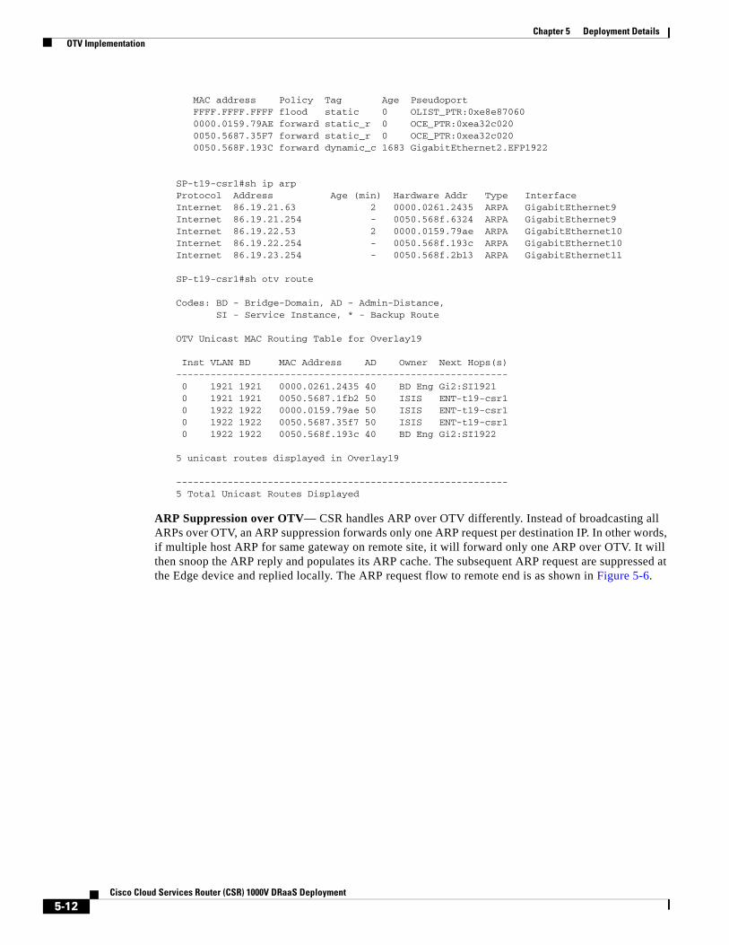
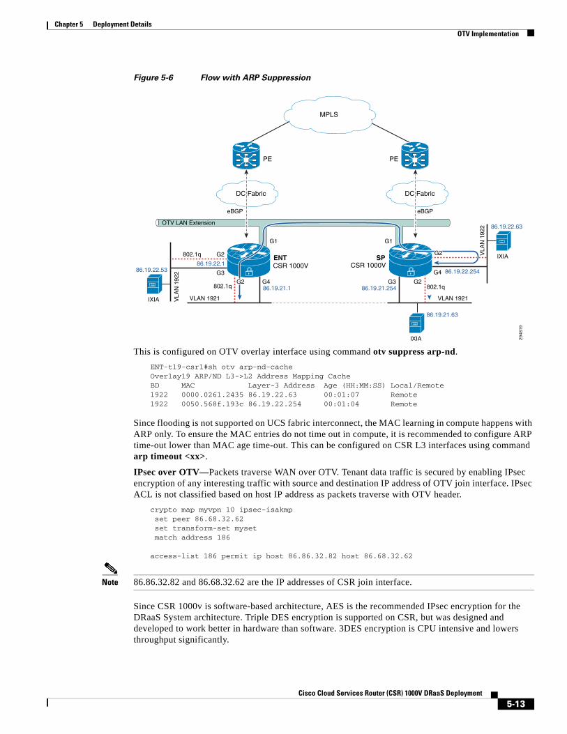
ARP Suppression over OTV— CSR handles ARP over OTV differently. Instead of broadcasting all ARPs over OTV, an ARP suppression forwards only one ARP request per destination IP. In other words, if multiple host ARP for same gateway on remote site, it will forward only one ARP over OTV. It will then snoop the ARP reply and populates its ARP cache. The subsequent ARP request are suppressed at the Edge device and replied locally. The ARP request flow to remote end is as shown in Figure 5-6.
5-12Cisco Cloud Services Router (CSR) 1000V DRaaS Deployment
Chapter 5 Deployment Details OTV Implementation
Figure 5-6 Flow with ARP Suppression
This is configured on OTV overlay interface using command otv suppress arp-nd.
ENT-t19-csr1#sh otv arp-nd-cache Overlay19 ARP/ND L3->L2 Address Mapping CacheBD MAC Layer-3 Address Age (HH:MM:SS) Local/Remote1922 0000.0261.2435 86.19.22.63 00:01:07 Remote1922 0050.568f.193c 86.19.22.254 00:01:04 Remote
Since flooding is not supported on UCS fabric interconnect, the MAC learning in compute happens with ARP only. To ensure the MAC entries do not time out in compute, it is recommended to configure ARP time-out lower than MAC age time-out. This can be configured on CSR L3 interfaces using command arp timeout <xx>.
IPsec over OTV—Packets traverse WAN over OTV. Tenant data traffic is secured by enabling IPsec encryption of any interesting traffic with source and destination IP address of OTV join interface. IPsec ACL is not classified based on host IP address as packets traverse with OTV header.
crypto map myvpn 10 ipsec-isakmp set peer 86.68.32.62 set transform-set myset match address 186
access-list 186 permit ip host 86.86.32.82 host 86.68.32.62
Note 86.86.32.82 and 86.68.32.62 are the IP addresses of CSR join interface.
Since CSR 1000v is software-based architecture, AES is the recommended IPsec encryption for the DRaaS System architecture. Triple DES encryption is supported on CSR, but was designed and developed to work better in hardware than software. 3DES encryption is CPU intensive and lowers throughput significantly.
G4
MPLS
DC FabricDC Fabric
2948
19
PE
CSR 1000V CSR 1000VENT SP
PE
VLAN 1921
IXIA
eBGP
OTV LAN Extension
eBGP
802.1q
86.19.21.1
86.19.22.1
86.19.21.254
86.19.22.25486.19.22.53
86.19.21.63
G2G3
G1G1
G4
G3
G2
802.1q
VLAN 1921VLA
N 1
922
VLA
N 1
922
IXIA
86.19.22.63
IXIA
802.1qG2
G2
5-13Cisco Cloud Services Router (CSR) 1000V DRaaS Deployment
Chapter 5 Deployment Details LISP Implementation
AES Configurationcrypto ipsec transform-set myset esp-aes esp-md5-hmac
3DES Configurationcrypto ipsec transform-set myset esp-3des esp-md5-hmac
MAC Move across OTV—OTV supports VM mobility and is a critical feature for the DRaaS System architecture. OTV supports the move of servers from one data center to the other data center using IS-IS protocol. Generally, IS-IS advertises the MAC of the VM with a metric of one, but when the move happens, the new site learns the same MAC on a local port, and it then advertises the same MAC with the metric of zero. The new update updates the new route on all end devices in the OTV domain. Once the old end device stops advertising, the new end device advertises with metric of one instead of zero.
OTV Fragmentation—OTV fragmentation depends on the OTV path MTU. Since it has to account for OTV header and IPsec header, if encryption is enabled, the received packet size needs to be 1472 or 1372 bytes, respectively. See more details in the Best Practices/Caveats section. CSR can set DF bit in the IP header to 0, using the otv fragmentation join-interface <interface> command. By default, DF bit will be set to 1.
LISP ImplementationThe Cisco LISP Virtual Machine Mobility (LISP VM-Mobility) solution allows any host to move anywhere in the network while preserving its IP address. The capability allows members of a subnet to be dispersed across many locations without requiring any changes on the hosts and while maintaining optimal routing and scalability in the network. LISP is a simple, incremental, network-based implementation that can be deployed on the CSR 1000V. It requires no changes to host stacks, DNS, or local network infrastructure, and little to no major changes to existing network infrastructures. In this section, we will look at how LISP could be deployed in a DRaaS System.
LISP Infrastructure ComponentsThe LISP architecture defines seven new network infrastructure components. The components include an Ingress Tunnel Router (ITR), Egress Tunnel Router (ETR), Map Server, Map Resolver, ALT Router, Proxy Ingress Tunnel Router (PITR), and Proxy Ingress Egress Router (PETR). In some cases, a single physical device can implement more than one of these logical components.
xTR—ITR / ETR
The network design and performance requirements of the DRaaS System permit us to implement multiple logical LISP components onto a single CSR1000v. The CSR1000v can provide the ITR, ETR, Map Server, and Map Resolver LISP functions.
Configuring LISP xTR Router
The procedure below demonstrates how to configure the xTR router to support these LISP functions.
Step 1 Define the RLOC associated with the EID prefixes.
hostname West-DC!router lisp
5-14Cisco Cloud Services Router (CSR) 1000V DRaaS Deployment

Chapter 5 Deployment Details LISP Implementation
locator-set West-DC 11.1.5.1 priority 1 weight 100 Exit
Step 2 Create a dynamic EID policy to define which VLANs in the data center will support LISP VM Mobility. The database command defines the EID to RLOC mapping relationship, so when an EID is discovered the dynamic EID will be registered to the Map Server with the locator-set (RLOC) defined in Step 1. In this example, two VLANs support LISP VM Mobility.
eid-table default instance-id 0 database-mapping 8.24.0.0/16 locator-set West-DC dynamic-eid vlan2481 database-mapping 8.24.81.0/24 locator-set West-DC exit ! dynamic-eid vlan2482 database-mapping 8.24.82.0/24 locator-set West-DC exit ! Exit
Note All database-mapping dynamic-EID commands must be consistent on all LISP VM Mobility routers supporting the same roaming dynamic EID.
Step 3 Use the following commands on the CSR 1000v to make the data center router an xTR, which will provide both ITR and ETR LISP functions.
ipv4 itr ipv4 etr
Step 4 Enable the Map Server and Map Resolver LISP functions on the xTR and configure the site details for LISP VM Mobility. Site attributes must be configured before an ETR can register with a Map Server. At a minimum, the EID prefixes to be registered by the ETR and a shared authentication key are required before an ETR is permitted to register EID prefixes with the Map Server. In this example, we use the accept-more-specifics attribute in the eid-prefix command to allow registration of any more specific eid-prefix that falls within the EID prefix 8.24.0.0/16.
site EastWestDC authentication-key cisco eid-prefix 8.24.0.0/16 accept-more-specifics exit ! ipv4 map-server ipv4 map-resolver
Step 5 The xTR in each data center will perform Map Server (MS) and Map Resolver (MR) functions allowing for MS/MR redundancy. Configure the locations of each MS and MR.
ipv4 itr map-resolver 11.1.5.1 ipv4 itr map-resolver 8.34.82.10 ! ipv4 etr map-server 11.1.5.1 key cisco ipv4 etr map-server 8.34.82.10 key cisco
Step 6 Configure the location of the PxTR that we will use for routing LISP packets to non-LISP sites. When a packet arrives from inside the data center, the xTR performs a destination lookup in the routing table. If the lookup results in a match, the packet is forwarded natively. If there is no matching route in the routing table, the IP source of the packet will determine if the packet is dropped or LISP encapsulated. A packet whose source IP is a dynamic EID then packet is LISP encapsulated, if it is not the packet is dropped.
5-15Cisco Cloud Services Router (CSR) 1000V DRaaS Deployment

Chapter 5 Deployment Details LISP Implementation
ipv4 use-petr 6.126.104.130
Step 7 Enable LISP VM Mobility on the CSR 1000v server facing interfaces. The lisp mobility name must match one of the dynamic EID policies defined in Step 2. The lisp extended-subnet-mode command is used when a subnet is extended across a L3 cloud using an L2 extension technology such as OTV.
interface GigabitEthernet3 description VLAN 2481 Layer 3 Interface ip address 8.24.81.2 255.255.255.0 standby 0 ip 8.24.81.1 lisp mobility vlan2481 lisp extended-subnet-mode
Step 8 Repeat the LISP VM Mobility configuration for the xTR router located in the East-DC.
hostname East-DC!router lisp locator-set East-DC 8.34.82.10 priority 1 weight 100 exit ! eid-table default instance-id 0 database-mapping 8.24.0.0/16 locator-set East-DC dynamic-eid vlan2481 database-mapping 8.24.81.0/24 locator-set East-DC exit ! dynamic-eid vlan2482 database-mapping 8.24.82.0/24 locator-set East-DC exit ! exit ! site EastWestDC authentication-key cisco eid-prefix 8.24.0.0/16 accept-more-specifics exit ! ipv4 map-server ipv4 map-resolver ipv4 map-request-source 8.34.82.10 ipv4 use-petr 6.126.104.130 ipv4 itr map-resolver 11.1.5.1 ipv4 itr map-resolver 8.34.82.10 ipv4 itr ipv4 etr map-server 11.1.5.1 key cisco ipv4 etr map-server 8.34.82.10 key cisco ipv4 etr !interface GigabitEthernet3 description VLAN 2481 Layer 3 Interface ip address 8.24.81.3 255.255.255.0 standby 0 ip 8.24.81.1 lisp mobility vlan2481 lisp extended-subnet-mode
5-16Cisco Cloud Services Router (CSR) 1000V DRaaS Deployment
Chapter 5 Deployment Details General Routing Policy
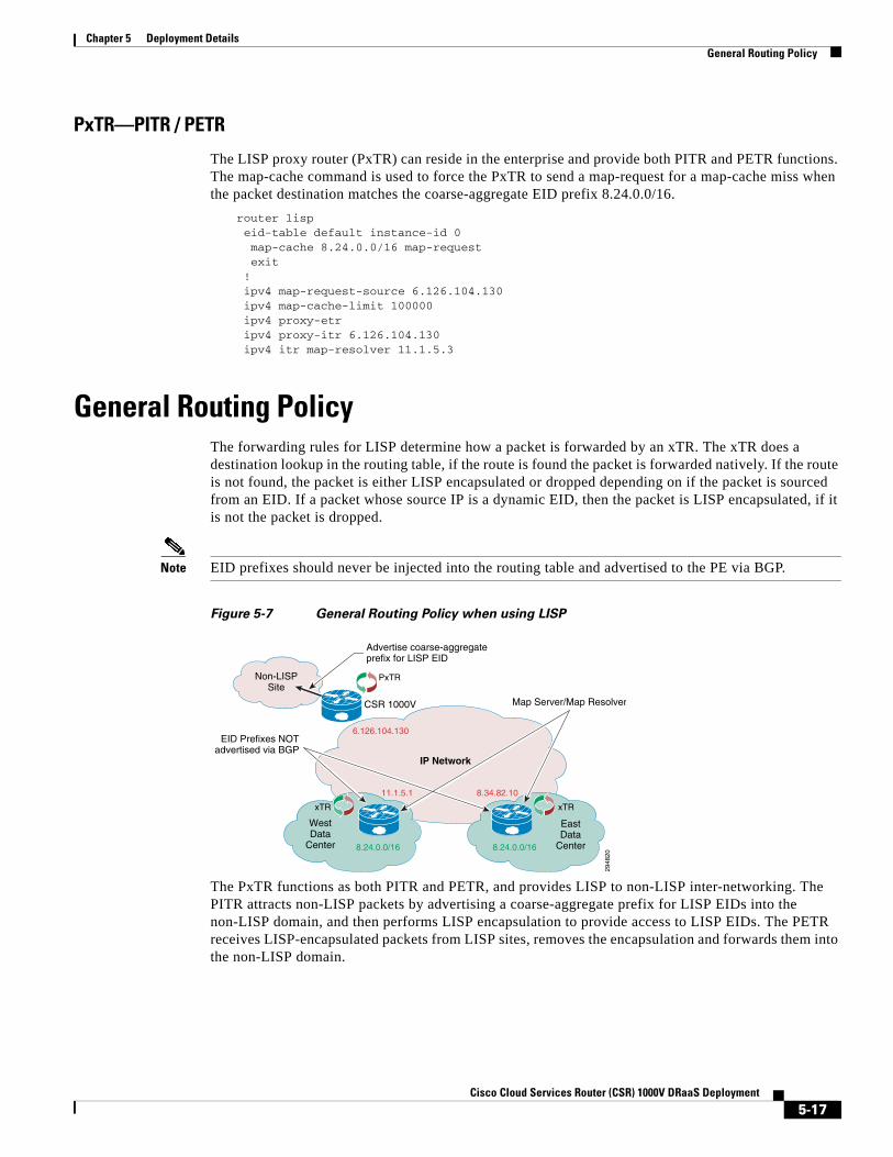
PxTR—PITR / PETR
The LISP proxy router (PxTR) can reside in the enterprise and provide both PITR and PETR functions. The map-cache command is used to force the PxTR to send a map-request for a map-cache miss when the packet destination matches the coarse-aggregate EID prefix 8.24.0.0/16.
router lisp eid-table default instance-id 0 map-cache 8.24.0.0/16 map-request exit ! ipv4 map-request-source 6.126.104.130 ipv4 map-cache-limit 100000 ipv4 proxy-etr ipv4 proxy-itr 6.126.104.130 ipv4 itr map-resolver 11.1.5.3
General Routing PolicyThe forwarding rules for LISP determine how a packet is forwarded by an xTR. The xTR does a destination lookup in the routing table, if the route is found the packet is forwarded natively. If the route is not found, the packet is either LISP encapsulated or dropped depending on if the packet is sourced from an EID. If a packet whose source IP is a dynamic EID, then the packet is LISP encapsulated, if it is not the packet is dropped.
Note EID prefixes should never be injected into the routing table and advertised to the PE via BGP.
Figure 5-7 General Routing Policy when using LISP
The PxTR functions as both PITR and PETR, and provides LISP to non-LISP inter-networking. The PITR attracts non-LISP packets by advertising a coarse-aggregate prefix for LISP EIDs into the non-LISP domain, and then performs LISP encapsulation to provide access to LISP EIDs. The PETR receives LISP-encapsulated packets from LISP sites, removes the encapsulation and forwards them into the non-LISP domain.
2948
20
Advertise coarse-aggregateprefix for LISP EID
Map Server/Map Resolver
EID Prefixes NOTadvertised via BGP
PxTR
xTRxTR
Non-LISPSite
IP Network
6.126.104.130
11.1.5.1 8.34.82.10
8.24.0.0/16 8.24.0.0/16
WestData
Center
CSR 1000V
EastData
Center
5-17Cisco Cloud Services Router (CSR) 1000V DRaaS Deployment

Chapter 5 Deployment Details Firewall Policy
Firewall PolicyThe CSR1000V provides firewall services through the use of zoned-based firewall. The DRaaS System implements a three-zone implementation:
• The inside zone applies to any server-facing interface and will provide a security policy for inter-VLAN native IP traffic that is confined to the data center.
• The outside zone applies to the northbound interface and will provide a security policy for northbound native IP traffic.
• The LISP0 interface is where LISP encapsulation and decapsulation occurs. The LISP zone is applied to the logical LISP0 interface which defines the security policy for LISP encapsulated packets. Two traffic flows need to be considered when applying a zone-based firewall for LISP encapsulated packets:
– LISP-to-NON-LISP traffic flows to/from the PxTR, and LISP to LISP traffic flows to/from a remote LISP site.
– LISP-to-LISP inter-VLAN traffics flows between EIDs located in different data centers.
Figure 5-8 CSR1000V Configured Zones
The zone-pair is used to define the security policy between zones. The example below demonstrates how an inter-zone security policy might be applied to support the requirements shown in Figure 5-8. First, create the zones and define the security policies between zones.
zone security outsidezone security insidezone security lispzone-pair security inside-to-inside source inside destination inside service-policy type inspect inside-to-insidezone-pair security inside-to-lisp source inside destination lisp service-policy type inspect inside-to-lispzone-pair security inside-to-outside source inside destination outside service-policy type inspect inside-to-outsidezone-pair security lisp-to-inside source lisp destination inside service-policy type inspect lisp-to-insidezone-pair security outside-to-inside source outside destination inside service-policy type inspect outside-to-inside
2947
71
CSR 1000V
xTR
LISP0 G1
G3 G4 G5
Outside
InsideInsideInside
LISP
5-18Cisco Cloud Services Router (CSR) 1000V DRaaS Deployment
Chapter 5 Deployment Details LISP Control Plane
The appropriate security zone is then applied to the physical interface. The security zone for LISP traffic is applied to the virtual interface LISP0. The virtual interface is where LISP encapsulation and decapsulation occurs, allowing the firewall to inspect egress packets before LISP encapsulation and ingress packets after LISP decapsulation. With the virtual interface we can now have different security policies for LISP and native IP traffic applied to a single physical interface.
int lisp0 description LISP Encap/Decap zone-member security lispinterface GigabitEthernet1 description Uplink to DC Fabric zone-member security outsideinterface GigabitEthernet3 description L3 Interface VLAN 2481 - LISP Dynamic EID zone-member security insideinterface GigabitEthernet4 description L3 Interface VLAN 2482 - LISP Dynamic EID zone-member security insideinterface GigabitEthernet5 description L3 Interface VLAN 2483 - LISP Dynamic EID zone-member security inside
LISP Control PlaneLISP control plane packets are UDP-based messages. The IANA registry has allocated UDP port numbers 4341 LISP data packets and 4342 for LISP control packets. The LISP control message packet format is shown in Figure 5-9. The five LISP control plane message types are currently:
• Map-Request
• Map-Reply
• Map-Register
• Map-Notify
• Encapsulated Control Message
Figure 5-9 LISP Control Plane Packet Format
Map-Request
This message is sent by an ITR to the mapping database when it needs to send a packet to a destination EID for which is has no cached RLOC.
2947
63
0 1
Version IHL Type of Service Total Length
Fragment OffsetFlagsIdentification
Time to Live
Source Port (xxxx) Destination Port (4342)
UDP LengthUDP
IPv4 OuterHeader
LISPHeader
UDP Checksum
Protocol (17) Header Checksum
Source Routing Locator
Destination Routing Locator
12 3 4 5 6 7
LISP Message
8 9 0 1 2 3 4 5 6 7 8 9 0 1 0 122
33
4 5 6 7 8 9
5-19Cisco Cloud Services Router (CSR) 1000V DRaaS Deployment

Chapter 5 Deployment Details LISP Control Plane
Map-Reply
This message is returned to an ITR by an ETR or map server in response to a Map-Request message. A Map-Reply message contains the EID prefix that matches the requested destination EID along with a set of RLOCs that can be used as the destination IP addresses for encapsulating user data.
Map-Register
This message is sent by an ETR to a map server to specify an EID prefix that it owns as well as the RLOCs that should be used for exchanging Map-Request and Map-Reply messages. Registration request includes the EID prefix, prefix length, RLOCs associated with the prefix, and priorities and traffic sharing weights of each RLOC. Map-Register messages are sent periodically to maintain the registration state between an ETR and its map servers.
Map-Notify
A LISP message sent by a Map-Server to an ETR to confirm that a Map-Register has been received and processed. The Map-Notify message uses UDP port number 4342 for both source and destination.
Encapsulated Control Message
This message is a Map-Request message that is encapsulated within an Encapsulated Control Message. It is sent from an ITR to a Map-Resolver and by a Map-Server when forwarding a Map-Request to an ETR.
The RLOC or Record Locator is the IP address of the ETR. The RLOC is the output of an EID to RLOC mapping lookup on the ITR. The resulting lookup produces an EID mapping to one or more RLOCs. When a packet arrives at an ITR, a route lookup occurs and a forwarding decision is made. If the route is found or a default route exists, the packet is forwarded natively. Otherwise, the packet is either LISP encapsulated or dropped. When a packet meets the criteria for LISP forwarding, the steps to locate the EID to RLOC binding or mapping is shown in Figure 5-10.
Figure 5-10 LISP Control Plane during a LISP VM Mobility Event
Non-LISPSitesMPLS
DC FabricDC Fabric
2947
64
PE
Nexus 7000Nexus 7000
CSR 1000V CSR 1000VEast DCWest DC
PE
VLAN 2481
H1
eBGP
OTV LAN Extension
PxTR
eBGP
S1
3.3.3.40
802.1q
Map-R
eply
Map-Request
8.24.81.0/248.24.81.0/24
8.24.81.40
G2G3
G1G1
G3G2802.1q
VLAN 2481
RLOC: 6.126.104.130
RLOC: 8.34.82.10RLOC: 11.1.5.1
xTR xTR
Map
-Reg
iste
r
Map
-Req
uest
5
4
2MRMS 3
1
MS = Map ServerMR = Map Resolver
5-20Cisco Cloud Services Router (CSR) 1000V DRaaS Deployment
Chapter 5 Deployment Details LISP VM Mobility
The following steps are required for an ITR to retrieve valid mapping information from the mapping database:
1. The ETRs first register their EID prefixes with the Map-Server. In this instance, West-DC would register both 8.24.81.0/24 and 8.24.81.40/32 EID prefixes, while East-DC would only register EID prefix 8.24.81.0/24. Each ETR will send Map-Registration messages every 60 seconds.
2. H1 sends a packet to S1, and no entry for S1 exists in the local map-cache of the PXTR. The PITR sends a Map-Request message to the Map-Resolver.
3. The Map-Resolver forwards the Map-Request message to the Map-Server.
4. The Map-Server forwards the Map-Request to the ETR that last registered the EID prefix.
5. The ETR sends a Map-Reply to the PITR containing the requested mapping information.
Note In the DRaaS System, the Map-Resolver and Map-Server function can both be installed on the LISP data center router for redundancy. In addition, both Map-Resolver and Map-Server functions can be enabled on each data center LISP router.
LISP VM MobilityLISP VM Mobility supports both Across Subnet Mode (ASM) and Extended Subnet Mode (ESM). For the DRaaS use case, LISP VM Mobility using ESM is required to enable support for partial failover. This would enable servers that send non-routable heartbeat messages to operate during a partial failover.
LISP VM Mobility ESM PrerequisitesEnabling LISP VM Mobility with an extended subnet has some prerequisites.
The default gateway (FHR) for each server VLAN should use the same IP and MAC in both data centers. This can be accomplished by enabling HSRP on the CSR 1000V server-facing L3 interfaces. It’s important to maintain FHRP isolation when using OTV. HSRP routers should never peer with other HSRP routers over OTV. The CSR 1000v OTV implementation by default filters FHRP control packets on the Overlay interface, which prevents HSRP peering across OTV (Figure 5-11).
5-21Cisco Cloud Services Router (CSR) 1000V DRaaS Deployment
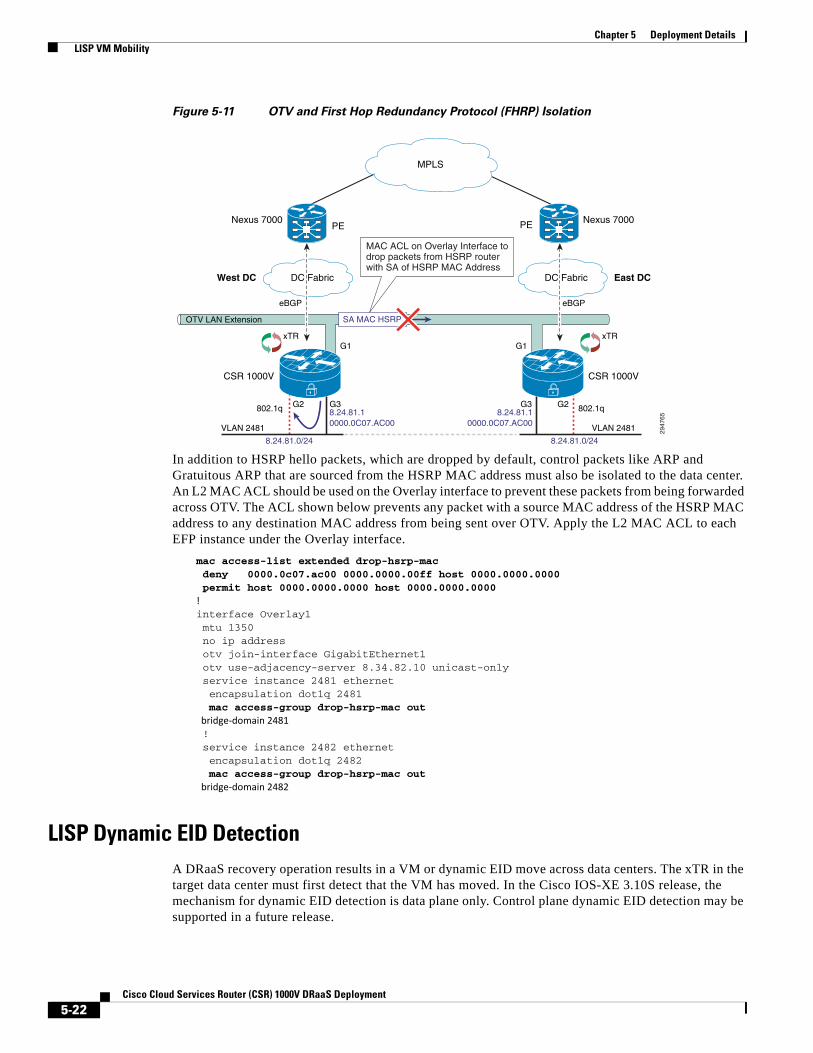
Chapter 5 Deployment Details LISP VM Mobility
Figure 5-11 OTV and First Hop Redundancy Protocol (FHRP) Isolation
In addition to HSRP hello packets, which are dropped by default, control packets like ARP and Gratuitous ARP that are sourced from the HSRP MAC address must also be isolated to the data center. An L2 MAC ACL should be used on the Overlay interface to prevent these packets from being forwarded across OTV. The ACL shown below prevents any packet with a source MAC address of the HSRP MAC address to any destination MAC address from being sent over OTV. Apply the L2 MAC ACL to each EFP instance under the Overlay interface.
mac access-list extended drop-hsrp-mac deny 0000.0c07.ac00 0000.0000.00ff host 0000.0000.0000 permit host 0000.0000.0000 host 0000.0000.0000!interface Overlay1 mtu 1350 no ip address otv join-interface GigabitEthernet1 otv use-adjacency-server 8.34.82.10 unicast-only service instance 2481 ethernet encapsulation dot1q 2481 mac access-group drop-hsrp-mac out bridge-domain 2481 ! service instance 2482 ethernet encapsulation dot1q 2482 mac access-group drop-hsrp-mac out bridge-domain 2482
LISP Dynamic EID DetectionA DRaaS recovery operation results in a VM or dynamic EID move across data centers. The xTR in the target data center must first detect that the VM has moved. In the Cisco IOS-XE 3.10S release, the mechanism for dynamic EID detection is data plane only. Control plane dynamic EID detection may be supported in a future release.
MPLS
DC FabricDC Fabric
2947
65
PE
East DCWest DC
PE
VLAN 2481
eBGP
OTV LAN Extension
eBGP
802.1q8.24.81.10000.0C07.AC00
8.24.81.10000.0C07.AC00
8.24.81.0/248.24.81.0/24
G2G3
G1G1
G3G2802.1q
VLAN 2481
SA MAC HSRP
xTR xTR
MAC ACL on Overlay Interface todrop packets from HSRP routerwith SA of HSRP MAC Address
Nexus 7000Nexus 7000
CSR 1000V CSR 1000V
5-22Cisco Cloud Services Router (CSR) 1000V DRaaS Deployment
Chapter 5 Deployment Details LISP VM Mobility
A dynamic EID move is detected when the xTR receives a unicast IP packet from the VM. The xTR registers the dynamic EID with the Map-Server causing LISP to direct traffic to the VMs new location. LISP control plane debugs can be used to show when a dynamic EID has been detected. The debug output below shows two instances where a dynamic EID is detected. The first PD detect is a multicast packet that is ignored by the xTR, and the second packet results in dynamic EID being detected.
Nov 9 02:48:31.021: LISPdyn-EID: PD detected IPv4:Default:86.21.21.40 on GigabitEthernet3Nov 9 02:48:31.021: LISPdyn-EID: Ignoring detection from multicast packet IPv4:Default:86.21.21.40 to 224.0.0.252 on GigabitEthernet3
Nov 9 02:48:34.944: LISPdyn-EID: PD detected IPv4:Default:86.21.21.40 on GigabitEthernet3
In a Windows environment where NetBIOS over IP is enabled on servers residing in the data center, an inbound L3 ACL should be applied to the CSR server-facing L3 interfaces to drop NetBIOS over IP packets. Adding an L3 ACL to drop NetBIOS over IP packets will help speed up the time it takes LISP to converge after a VM mobility event.
A DRaaS recovery is effectively a VM Mobility event, where the target VM is powered up in the remote data center. The LISP router in the remote DC must first detect that the VM has moved. If the VM is running Windows OS with NetBIOS over IP enabled, the VM will send multiple NetBIOS over IP packets on the wire during the boot up process. These packets are sent to the subnet broadcast address, see packet format below, which will be forwarded to both the local DC LISP router and the remote DC LISP router via OTV. NetBIOS over IP packets will trigger a dynamic EID detection, so each time the VM sends out a NetBIOS over IP packet the dynamic EID is detected by LISP routers in both DCs. This constant relearning of the dynamic EID between local and remote data centers will cause packet loss until the Windows PC stops sending NetBIOS over IP packets.
NetBIOS over IP Packet FormatFrame 17: 110 bytes on wire (880 bits), 110 bytes captured (880 bits)Ethernet II, Src: Olicom_81:00:40 (00:00:24:81:00:40), Dst: Broadcast (ff:ff:ff:ff:ff:ff)Internet Protocol Version 4, Src: 8.24.81.40 (8.24.81.40), Dst: 8.24.81.255 (8.24.81.255)User Datagram Protocol, Src Port: netbios-ns (137), Dst Port: netbios-ns (137) Source port: netbios-ns (137) Destination port: netbios-ns (137) Length: 76 Checksum: 0xb3b4 [validation disabled]NetBIOS Name Service Transaction ID: 0xedfe Flags: 0x2910 (Registration) Questions: 1 Answer RRs: 0 Authority RRs: 0 Additional RRs: 1 Queries Additional records
One can avoid this problem in different ways. One method is to disable NetBIOS over IP on all Windows PCs in the data center. Figure 5-12 shows how to configure NetBIOS over IP.
5-23Cisco Cloud Services Router (CSR) 1000V DRaaS Deployment
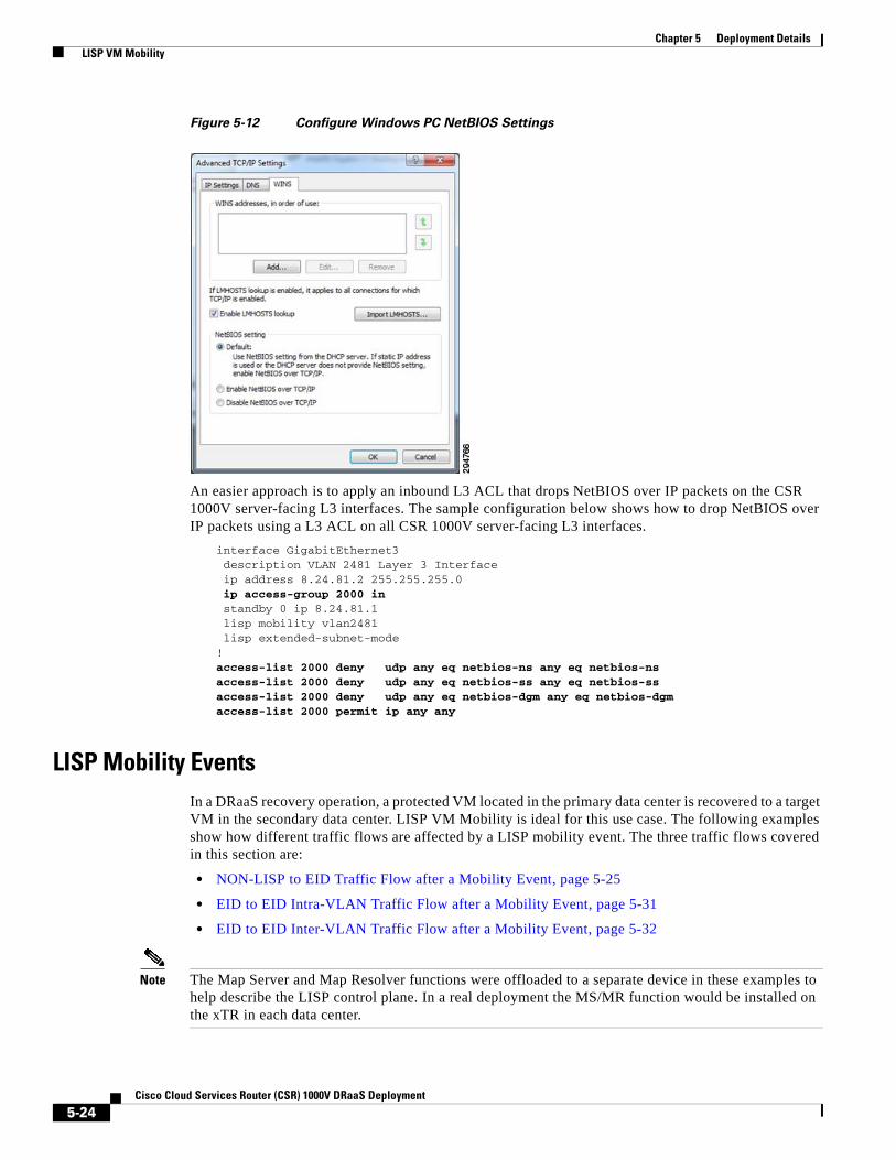
Chapter 5 Deployment Details LISP VM Mobility
Figure 5-12 Configure Windows PC NetBIOS Settings
An easier approach is to apply an inbound L3 ACL that drops NetBIOS over IP packets on the CSR 1000V server-facing L3 interfaces. The sample configuration below shows how to drop NetBIOS over IP packets using a L3 ACL on all CSR 1000V server-facing L3 interfaces.
interface GigabitEthernet3 description VLAN 2481 Layer 3 Interface ip address 8.24.81.2 255.255.255.0 ip access-group 2000 in standby 0 ip 8.24.81.1 lisp mobility vlan2481 lisp extended-subnet-mode!access-list 2000 deny udp any eq netbios-ns any eq netbios-nsaccess-list 2000 deny udp any eq netbios-ss any eq netbios-ssaccess-list 2000 deny udp any eq netbios-dgm any eq netbios-dgmaccess-list 2000 permit ip any any
LISP Mobility EventsIn a DRaaS recovery operation, a protected VM located in the primary data center is recovered to a target VM in the secondary data center. LISP VM Mobility is ideal for this use case. The following examples show how different traffic flows are affected by a LISP mobility event. The three traffic flows covered in this section are:
• NON-LISP to EID Traffic Flow after a Mobility Event, page 5-25
• EID to EID Intra-VLAN Traffic Flow after a Mobility Event, page 5-31
• EID to EID Inter-VLAN Traffic Flow after a Mobility Event, page 5-32
Note The Map Server and Map Resolver functions were offloaded to a separate device in these examples to help describe the LISP control plane. In a real deployment the MS/MR function would be installed on the xTR in each data center.
5-24Cisco Cloud Services Router (CSR) 1000V DRaaS Deployment

Chapter 5 Deployment Details LISP VM Mobility
NON-LISP to EID Traffic Flow after a Mobility EventFigure 5-13 describes communication to the EID from NON-LISP sites.
1. The original traffic flow from the PxTR to the DC is through the xTR in the West-DC.
2. User performs a DRaaS recovery operation resulting in the VM being moved to the East-DC.
3. Temporary sub-optimal routing through the xTR in the West-DC will occur before LISP converges.
4. LISP detects the VM move and routes NON-LISP to EID traffic from the PxTR to the xTR in the East-DC.
Figure 5-13 Non-LISP to EID Traffic Flow
The state of each LISP components prior to performing the DRaaS recovery operation is shown below. The Map Server shows xTR in the West-DC has registered the EID prefix 8.24.81.40/32 with the Map Server.
MS-MR#show lisp siteLISP Site Registration Information
Site Name Last Up Who Last Inst EID Prefix Register Registered ID EastWestDC 00:00:46 yes 11.1.5.1 8.24.0.0/16 00:00:46 yes 11.1.5.1 8.24.81.40/32
The PxTR local map-cache shows the current RLOC for the EID Prefix 8.24.81.40/32 is the West-DC xTR whose RLOC is 11.1.5.1. Traffic from H1 destined to H2 enters the data center through the xTR in the West-DC.
pxtr#show ip lisp map-cache LISP IPv4 Mapping Cache for EID-table default (IID 0), 2 entries
Non-LISPSitesMPLS
DC FabricDC Fabric
2947
67
PE
ASR 9000ASR 9000
CSR 1000V CSR 1000VEast DCWest DC
PE
VLAN 2481
H1
H2
eBGP
OTV LAN Extension
PxTR
eBGP
H2
3.3.3.40
802.1q8.24.81.18.24.81.1
8.24.81.0/248.24.81.0/248.24.81.40 8.24.81.40
11.1.5.3
G2G3
G1G1
DRaaS Recovery
G3G2802.1q
VLAN 2481
RLOC: 6.126.104.130
RLOC: 8.34.82.10RLOC: 11.1.5.1
xTR xTR
2
MS/MR
3
1
MS = Map ServerMR = Map Resolver
4
5-25Cisco Cloud Services Router (CSR) 1000V DRaaS Deployment
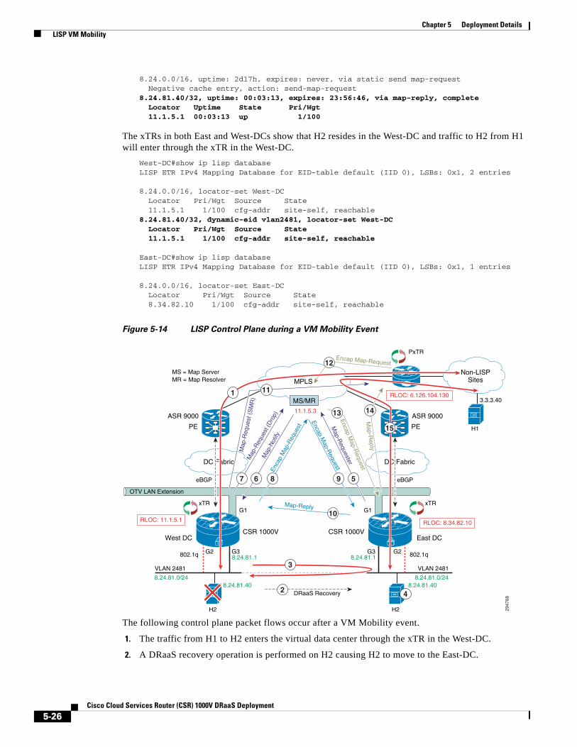
Chapter 5 Deployment Details LISP VM Mobility
8.24.0.0/16, uptime: 2d17h, expires: never, via static send map-request Negative cache entry, action: send-map-request8.24.81.40/32, uptime: 00:03:13, expires: 23:56:46, via map-reply, complete Locator Uptime State Pri/Wgt 11.1.5.1 00:03:13 up 1/100
The xTRs in both East and West-DCs show that H2 resides in the West-DC and traffic to H2 from H1 will enter through the xTR in the West-DC.
West-DC#show ip lisp database LISP ETR IPv4 Mapping Database for EID-table default (IID 0), LSBs: 0x1, 2 entries
8.24.0.0/16, locator-set West-DC Locator Pri/Wgt Source State 11.1.5.1 1/100 cfg-addr site-self, reachable8.24.81.40/32, dynamic-eid vlan2481, locator-set West-DC Locator Pri/Wgt Source State 11.1.5.1 1/100 cfg-addr site-self, reachable
East-DC#show ip lisp database LISP ETR IPv4 Mapping Database for EID-table default (IID 0), LSBs: 0x1, 1 entries
8.24.0.0/16, locator-set East-DC Locator Pri/Wgt Source State 8.34.82.10 1/100 cfg-addr site-self, reachable
Figure 5-14 LISP Control Plane during a VM Mobility Event
The following control plane packet flows occur after a VM Mobility event.
1. The traffic from H1 to H2 enters the virtual data center through the xTR in the West-DC.
2. A DRaaS recovery operation is performed on H2 causing H2 to move to the East-DC.
Non-LISPSitesMPLS
DC FabricDC Fabric
2947
68
PE
ASR 9000ASR 9000
CSR 1000V CSR 1000VEast DCWest DC
PE
VLAN 2481
H1
H2
eBGP
OTV LAN Extension
PxTR
eBGP
H2
3.3.3.40
802.1q
Map-Reply
Map-R
eply
Enca
p M
ap-R
eque
st
Map
-Not
ify
Encap M
ap-Request
Encap Map-Request
Encap M
ap-Request
Map-R
equester
8.24.81.18.24.81.1
8.24.81.0/248.24.81.0/248.24.81.40 8.24.81.40
11.1.5.3
G2G3
G1G1
DRaaS Recovery
G3G2802.1q
VLAN 2481
RLOC: 6.126.104.130
RLOC: 8.34.82.10RLOC: 11.1.5.1
xTR xTR
10
Map
-Req
uest
(Dro
p)
Map
-Req
uest
(S
MR
)
8 567 9
4
11
12
1413
2
MS/MR
3
1
15
MS = Map ServerMR = Map Resolver
5-26Cisco Cloud Services Router (CSR) 1000V DRaaS Deployment
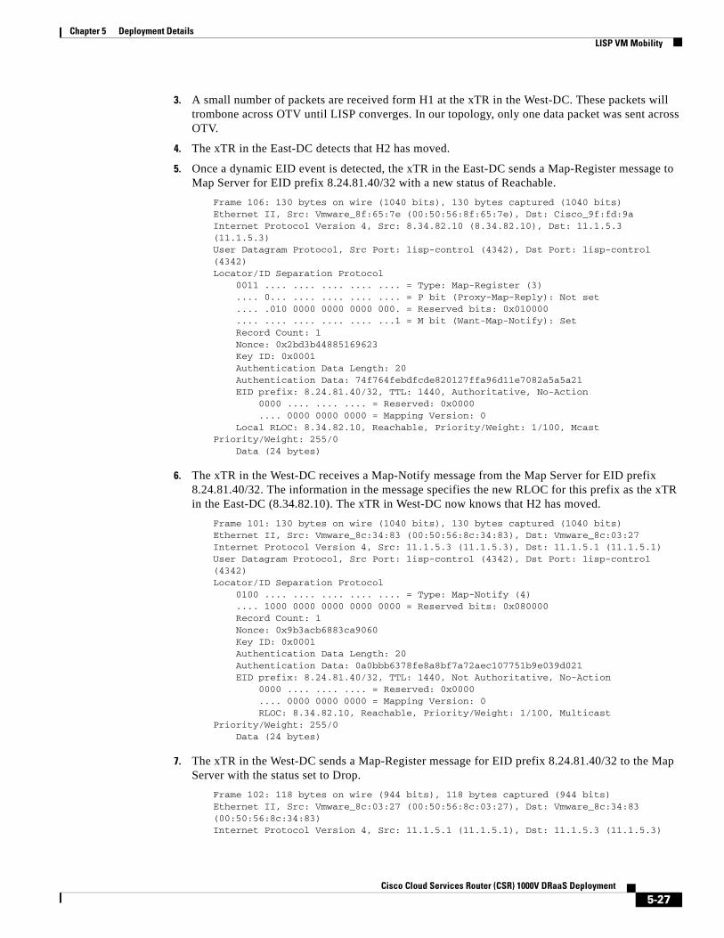
Chapter 5 Deployment Details LISP VM Mobility
3. A small number of packets are received form H1 at the xTR in the West-DC. These packets will trombone across OTV until LISP converges. In our topology, only one data packet was sent across OTV.
4. The xTR in the East-DC detects that H2 has moved.
5. Once a dynamic EID event is detected, the xTR in the East-DC sends a Map-Register message to Map Server for EID prefix 8.24.81.40/32 with a new status of Reachable.
Frame 106: 130 bytes on wire (1040 bits), 130 bytes captured (1040 bits)Ethernet II, Src: Vmware_8f:65:7e (00:50:56:8f:65:7e), Dst: Cisco_9f:fd:9a Internet Protocol Version 4, Src: 8.34.82.10 (8.34.82.10), Dst: 11.1.5.3 (11.1.5.3)User Datagram Protocol, Src Port: lisp-control (4342), Dst Port: lisp-control (4342)Locator/ID Separation Protocol 0011 .... .... .... .... .... = Type: Map-Register (3) .... 0... .... .... .... .... = P bit (Proxy-Map-Reply): Not set .... .010 0000 0000 0000 000. = Reserved bits: 0x010000 .... .... .... .... .... ...1 = M bit (Want-Map-Notify): Set Record Count: 1 Nonce: 0x2bd3b44885169623 Key ID: 0x0001 Authentication Data Length: 20 Authentication Data: 74f764febdfcde820127ffa96d11e7082a5a5a21 EID prefix: 8.24.81.40/32, TTL: 1440, Authoritative, No-Action 0000 .... .... .... = Reserved: 0x0000 .... 0000 0000 0000 = Mapping Version: 0 Local RLOC: 8.34.82.10, Reachable, Priority/Weight: 1/100, Mcast Priority/Weight: 255/0 Data (24 bytes)
6. The xTR in the West-DC receives a Map-Notify message from the Map Server for EID prefix 8.24.81.40/32. The information in the message specifies the new RLOC for this prefix as the xTR in the East-DC (8.34.82.10). The xTR in West-DC now knows that H2 has moved.
Frame 101: 130 bytes on wire (1040 bits), 130 bytes captured (1040 bits)Ethernet II, Src: Vmware_8c:34:83 (00:50:56:8c:34:83), Dst: Vmware_8c:03:27 Internet Protocol Version 4, Src: 11.1.5.3 (11.1.5.3), Dst: 11.1.5.1 (11.1.5.1)User Datagram Protocol, Src Port: lisp-control (4342), Dst Port: lisp-control (4342)Locator/ID Separation Protocol 0100 .... .... .... .... .... = Type: Map-Notify (4) .... 1000 0000 0000 0000 0000 = Reserved bits: 0x080000 Record Count: 1 Nonce: 0x9b3acb6883ca9060 Key ID: 0x0001 Authentication Data Length: 20 Authentication Data: 0a0bbb6378fe8a8bf7a72aec107751b9e039d021 EID prefix: 8.24.81.40/32, TTL: 1440, Not Authoritative, No-Action 0000 .... .... .... = Reserved: 0x0000 .... 0000 0000 0000 = Mapping Version: 0 RLOC: 8.34.82.10, Reachable, Priority/Weight: 1/100, Multicast Priority/Weight: 255/0 Data (24 bytes)
7. The xTR in the West-DC sends a Map-Register message for EID prefix 8.24.81.40/32 to the Map Server with the status set to Drop.
Frame 102: 118 bytes on wire (944 bits), 118 bytes captured (944 bits)Ethernet II, Src: Vmware_8c:03:27 (00:50:56:8c:03:27), Dst: Vmware_8c:34:83 (00:50:56:8c:34:83)Internet Protocol Version 4, Src: 11.1.5.1 (11.1.5.1), Dst: 11.1.5.3 (11.1.5.3)
5-27Cisco Cloud Services Router (CSR) 1000V DRaaS Deployment
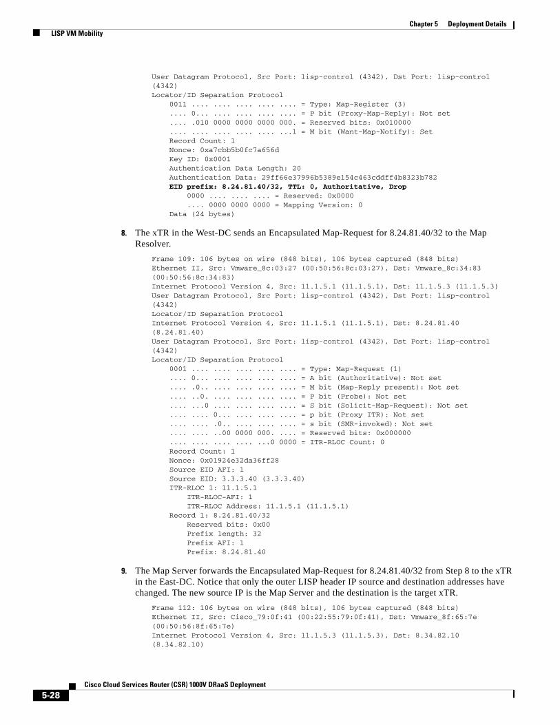
Chapter 5 Deployment Details LISP VM Mobility
User Datagram Protocol, Src Port: lisp-control (4342), Dst Port: lisp-control (4342)Locator/ID Separation Protocol 0011 .... .... .... .... .... = Type: Map-Register (3) .... 0... .... .... .... .... = P bit (Proxy-Map-Reply): Not set .... .010 0000 0000 0000 000. = Reserved bits: 0x010000 .... .... .... .... .... ...1 = M bit (Want-Map-Notify): Set Record Count: 1 Nonce: 0xa7cbb5b0fc7a656d Key ID: 0x0001 Authentication Data Length: 20 Authentication Data: 29ff66e37996b5389e154c463cddff4b8323b782 EID prefix: 8.24.81.40/32, TTL: 0, Authoritative, Drop 0000 .... .... .... = Reserved: 0x0000 .... 0000 0000 0000 = Mapping Version: 0 Data (24 bytes)
8. The xTR in the West-DC sends an Encapsulated Map-Request for 8.24.81.40/32 to the Map Resolver.
Frame 109: 106 bytes on wire (848 bits), 106 bytes captured (848 bits)Ethernet II, Src: Vmware_8c:03:27 (00:50:56:8c:03:27), Dst: Vmware_8c:34:83 (00:50:56:8c:34:83)Internet Protocol Version 4, Src: 11.1.5.1 (11.1.5.1), Dst: 11.1.5.3 (11.1.5.3)User Datagram Protocol, Src Port: lisp-control (4342), Dst Port: lisp-control (4342)Locator/ID Separation ProtocolInternet Protocol Version 4, Src: 11.1.5.1 (11.1.5.1), Dst: 8.24.81.40 (8.24.81.40)User Datagram Protocol, Src Port: lisp-control (4342), Dst Port: lisp-control (4342)Locator/ID Separation Protocol 0001 .... .... .... .... .... = Type: Map-Request (1) .... 0... .... .... .... .... = A bit (Authoritative): Not set .... .0.. .... .... .... .... = M bit (Map-Reply present): Not set .... ..0. .... .... .... .... = P bit (Probe): Not set .... ...0 .... .... .... .... = S bit (Solicit-Map-Request): Not set .... .... 0... .... .... .... = p bit (Proxy ITR): Not set .... .... .0.. .... .... .... = s bit (SMR-invoked): Not set .... .... ..00 0000 000. .... = Reserved bits: 0x000000 .... .... .... .... ...0 0000 = ITR-RLOC Count: 0 Record Count: 1 Nonce: 0x01924e32da36ff28 Source EID AFI: 1 Source EID: 3.3.3.40 (3.3.3.40) ITR-RLOC 1: 11.1.5.1 ITR-RLOC-AFI: 1 ITR-RLOC Address: 11.1.5.1 (11.1.5.1) Record 1: 8.24.81.40/32 Reserved bits: 0x00 Prefix length: 32 Prefix AFI: 1 Prefix: 8.24.81.40
9. The Map Server forwards the Encapsulated Map-Request for 8.24.81.40/32 from Step 8 to the xTR in the East-DC. Notice that only the outer LISP header IP source and destination addresses have changed. The new source IP is the Map Server and the destination is the target xTR.
Frame 112: 106 bytes on wire (848 bits), 106 bytes captured (848 bits)Ethernet II, Src: Cisco_79:0f:41 (00:22:55:79:0f:41), Dst: Vmware_8f:65:7e (00:50:56:8f:65:7e)Internet Protocol Version 4, Src: 11.1.5.3 (11.1.5.3), Dst: 8.34.82.10 (8.34.82.10)
5-28Cisco Cloud Services Router (CSR) 1000V DRaaS Deployment

Chapter 5 Deployment Details LISP VM Mobility
User Datagram Protocol, Src Port: lisp-control (4342), Dst Port: lisp-control (4342)Locator/ID Separation Protocol 1000 .... .... .... .... .... = Type: Encapsulated Control Message (8) .... 0000 0000 0000 0000 0000 0000 0000 = Reserved bits: 0x00000000Internet Protocol Version 4, Src: 11.1.5.1 (11.1.5.1), Dst: 8.24.81.40 (8.24.81.40)User Datagram Protocol, Src Port: lisp-control (4342), Dst Port: lisp-control (4342)Locator/ID Separation Protocol 0001 .... .... .... .... .... = Type: Map-Request (1) .... 0... .... .... .... .... = A bit (Authoritative): Not set .... .0.. .... .... .... .... = M bit (Map-Reply present): Not set .... ..0. .... .... .... .... = P bit (Probe): Not set .... ...0 .... .... .... .... = S bit (Solicit-Map-Request): Not set .... .... 0... .... .... .... = p bit (Proxy ITR): Not set .... .... .0.. .... .... .... = s bit (SMR-invoked): Not set .... .... ..00 0000 000. .... = Reserved bits: 0x000000 .... .... .... .... ...0 0000 = ITR-RLOC Count: 0 Record Count: 1 Nonce: 0x01924e32da36ff28 Source EID AFI: 1 Source EID: 3.3.3.40 (3.3.3.40) ITR-RLOC 1: 11.1.5.1 ITR-RLOC-AFI: 1 ITR-RLOC Address: 11.1.5.1 (11.1.5.1) Record 1: 8.24.81.40/32 Reserved bits: 0x00 Prefix length: 32 Prefix AFI: 1 Prefix: 8.24.81.40
10. The xTR in the East-DC sends a Map-Reply message to the West-DC xTR for the EID prefix 8.24.81.40/32.
11. The xTR in the West-DC sends a Map-Request message to the PxTR with the Solicit-Map-Request (SMR) bit set.
Frame 110: 74 bytes on wire (592 bits), 74 bytes captured (592 bits)Ethernet II, Src: Vmware_8c:03:27 (00:50:56:8c:03:27), Dst: 84:78:ac:6b:98:63 (84:78:ac:6b:98:63)Internet Protocol Version 4, Src: 11.1.5.1 (11.1.5.1), Dst: 6.126.104.130 (6.126.104.130)User Datagram Protocol, Src Port: lisp-control (4342), Dst Port: lisp-control (4342)Locator/ID Separation Protocol 0001 .... .... .... .... .... = Type: Map-Request (1) .... 0... .... .... .... .... = A bit (Authoritative): Not set .... .0.. .... .... .... .... = M bit (Map-Reply present): Not set .... ..1. .... .... .... .... = P bit (Probe): Set .... ...1 .... .... .... .... = S bit (Solicit-Map-Request): Set .... .... 0... .... .... .... = p bit (Proxy ITR): Not set .... .... .0.. .... .... .... = s bit (SMR-invoked): Not set .... .... ..00 0000 001. .... = Reserved bits: 0x000001 .... .... .... .... ...0 0000 = ITR-RLOC Count: 0 Record Count: 1 Nonce: 0xde45c1c4ff5549c4 Source EID AFI: 1 Source EID: 8.24.81.40 (8.24.81.40) ITR-RLOC 1: 11.1.5.1 ITR-RLOC-AFI: 1 ITR-RLOC Address: 11.1.5.1 (11.1.5.1) Record 1: 3.3.3.40/32 Reserved bits: 0x00
5-29Cisco Cloud Services Router (CSR) 1000V DRaaS Deployment

Chapter 5 Deployment Details LISP VM Mobility
Prefix length: 32 Prefix AFI: 1 Prefix: 3.3.3.40
12. The PxTR sends an Encapsulated Map-Request message to the Map Resolver for 8.24.84.40/32.
Frame 102: 106 bytes on wire (848 bits), 106 bytes captured (848 bits)Ethernet II, Src: Vmware_a6:c4:ec (00:50:56:a6:c4:ec), Dst: Cisco_9f:f9:98 (00:00:0c:9f:f9:98)Internet Protocol Version 4, Src: 6.126.104.130 (6.126.104.130), Dst: 11.1.5.3 (11.1.5.3)User Datagram Protocol, Src Port: lisp-control (4342), Dst Port: lisp-control (4342)Locator/ID Separation Protocol 1000 .... .... .... .... .... = Type: Encapsulated Control Message (8) .... 0000 0000 0000 0000 0000 0000 0000 = Reserved bits: 0x00000000Internet Protocol Version 4, Src: 6.126.104.130 (6.126.104.130), Dst: 8.24.81.40 (8.24.81.40)User Datagram Protocol, Src Port: lisp-control (4342), Dst Port: lisp-control (4342)Locator/ID Separation Protocol 0001 .... .... .... .... .... = Type: Map-Request (1) .... 0... .... .... .... .... = A bit (Authoritative): Not set .... .0.. .... .... .... .... = M bit (Map-Reply present): Not set .... ..0. .... .... .... .... = P bit (Probe): Not set .... ...0 .... .... .... .... = S bit (Solicit-Map-Request): Not set .... .... 1... .... .... .... = p bit (Proxy ITR): Set .... .... .1.. .... .... .... = s bit (SMR-invoked): Set .... .... ..00 0000 000. .... = Reserved bits: 0x000000 .... .... .... .... ...0 0000 = ITR-RLOC Count: 0 Record Count: 1 Nonce: 0xfa9011f926fe962b Source EID AFI: 1 Source EID: 3.3.3.40 (3.3.3.40) ITR-RLOC 1: 6.126.104.130 ITR-RLOC-AFI: 1 ITR-RLOC Address: 6.126.104.130 (6.126.104.130) Record 1: 8.24.81.40/32 Reserved bits: 0x00 Prefix length: 32 Prefix AFI: 1 Prefix: 8.24.81.40
13. The Map Server forwards the Encapsulated Map-Request message from the PxTR to the xTR in the East-DC.
14. The xTR in the East-DC sends a Map-Reply message to the PxTR.
15. At this point LISP has converged and traffic from H1 to H2 begin to flow through the East-DC xTR.
The state of each LISP components following the DRaaS recovery operation is shown below. The Map Server shows the xTR located in the East-DC has registered the EID prefix 8.24.81.40/32 with the Map Server.
MS-MR#sh lisp siteLISP Site Registration Information
Site Name Last Up Who Last Inst EID Prefix Register Registered ID EastWestDC 00:00:27 yes 11.1.5.1 8.24.0.0/16 00:00:33 yes 8.34.82.10 8.24.81.40/32
The PxTR local map-cache shows the RLOC for the EID Prefix 8.24.81.40/32 has moved to West-DC xTR at RLOC address 8.34.82.10.
5-30Cisco Cloud Services Router (CSR) 1000V DRaaS Deployment
Chapter 5 Deployment Details LISP VM Mobility
pxtr#show ip lisp map-cache LISP IPv4 Mapping Cache for EID-table default (IID 0), 2 entries
8.24.0.0/16, uptime: 2d17h, expires: never, via static send map-request Negative cache entry, action: send-map-request8.24.81.40/32, uptime: 00:08:09, expires: 23:57:46, via map-reply, complete Locator Uptime State Pri/Wgt 8.34.82.10 00:02:13 up 1/100
The xTRs in both East and West-DCs show that H2 resides in the East-DC and traffic to H2 from H1 will enter through the xTR in the East-DC.
West-DC#show ip lisp database LISP ETR IPv4 Mapping Database for EID-table default (IID 0), LSBs: 0x1, 1 entries
8.24.0.0/16, locator-set West-DC Locator Pri/Wgt Source State 11.1.5.1 1/100 cfg-addr site-self, reachable
East-DC#show ip lisp database LISP ETR IPv4 Mapping Database for EID-table default (IID 0), LSBs: 0x1, 2 entries
8.24.0.0/16, locator-set East-DC Locator Pri/Wgt Source State 8.34.82.10 1/100 cfg-addr site-self, reachable8.24.81.40/32, dynamic-eid vlan2481, locator-set East-DC Locator Pri/Wgt Source State 8.34.82.10 1/100 cfg-addr site-self, reachable
EID to EID Intra-VLAN Traffic Flow after a Mobility EventFigure 5-15 describes intra-VLAN communication between EIDs.
1. The original L2 traffic flow between EIDs within the West-DC.
2. User performs a DRaaS recovery operation.
3. EID to EID L2 intra-VLAN traffic flows go over the OTV tunnel.
5-31Cisco Cloud Services Router (CSR) 1000V DRaaS Deployment
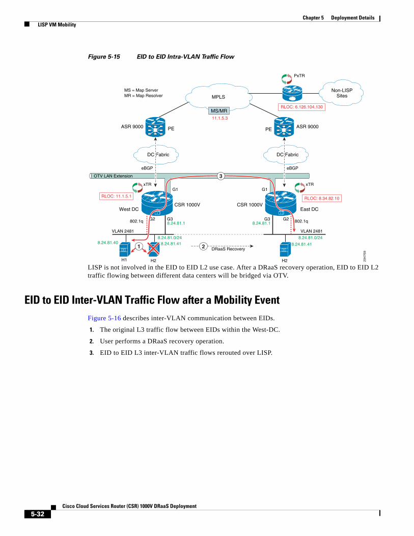
Chapter 5 Deployment Details LISP VM Mobility
Figure 5-15 EID to EID Intra-VLAN Traffic Flow
LISP is not involved in the EID to EID L2 use case. After a DRaaS recovery operation, EID to EID L2 traffic flowing between different data centers will be bridged via OTV.
EID to EID Inter-VLAN Traffic Flow after a Mobility EventFigure 5-16 describes inter-VLAN communication between EIDs.
1. The original L3 traffic flow between EIDs within the West-DC.
2. User performs a DRaaS recovery operation.
3. EID to EID L3 inter-VLAN traffic flows rerouted over LISP.
Non-LISPSitesMPLS
DC FabricDC Fabric
2947
69
PE ASR 9000ASR 9000
CSR 1000V CSR 1000VEast DCWest DC
PE
VLAN 2481
H1 H2
eBGP
OTV LAN Extension
PxTR
eBGP
MS = Map ServerMR = Map Resolver
H2
802.1q8.24.81.18.24.81.1
8.24.81.0/248.24.81.0/248.24.81.418.24.81.40 8.24.81.41
11.1.5.3
G2G3
G1G1
DRaaS Recovery
G3G2802.1q
VLAN 2481
RLOC: 6.126.104.130
RLOC: 8.34.82.10RLOC: 11.1.5.1
xTR xTR
2
MS/MR
3
1
5-32Cisco Cloud Services Router (CSR) 1000V DRaaS Deployment

Chapter 5 Deployment Details LISP VM Mobility
Figure 5-16 EID to EID Inter-VLAN Traffic Flow
This example shows the East to West EID to EID use case that covers inter-VLAN traffic flows across data centers. Inter-VLAN traffic flows within the DC are forwarded natively, but flows between EIDs in different data centers will be LISP encapsulated.
Non-LISPSitesMPLS
DC FabricDC Fabric
2947
70
PE
ASR 9000ASR 9000
CSR 1000V CSR 1000V
East DCWest DC
PE
VLAN 2481
H2
eBGP
OTV LAN Extension
PxTR
eBGP
H2
802.1q
802.1q
8.24.82.18.24.81.1
8.24.81.0/248.24.81.0/248.24.82.40 8.24.82.40
11.1.5.3
G2G4
G1G1
DRaaS Recovery
G4G2G2
G3
802.1q
VLAN 2482VLA
N 2
481
H1
8.24.81.40
RLOC: 6.126.104.130
RLOC: 8.34.82.10
RLOC: 11.1.5.1
xTR xTR
2
MS/MR
1
MS = Map ServerMR = Map Resolver
3
5-33Cisco Cloud Services Router (CSR) 1000V DRaaS Deployment

Chapter 5 Deployment Details LISP VM Mobility
5-34Cisco Cloud Services Router (CSR) 1000V DRaaS Deployment
Cisco Cloud Serv
A
P P E N D I X A Best Practices/CaveatsDRaaS solution architecture is integration of different technologies and partnership with different vendors. Caveats, workarounds, recommendations and issues identified in proof of concept (POC) testing have been documented in this chapter.
Key FindingsThe following key OTV and LISP findings are identified for consideration.
• OTV, page A-1
• LISP, page A-2
OTV • VMXNET3 is recommended driver for CSR vNICs
• Cisco IOS XE 3.10S does not support BDI MAC address learning over OTV. DDTS CSCuj59314 has been logged to track support of BDI over OTV.
• With vCenter vswitch, the security setting for promiscuous mode needs to be changed to Accept.
• When a vSwitch has more than one pNIC in it, the second pNIC (even if standby in an active/passive fail over) replicates back the ARP requests, causing the Linux bridge to incorrectly update its MAC table. The workarounds are as follows:
– Remove the second pNIC from the vSwitch; of course compromising redundancy.
– Replace the built in vSwitch with a Nexus 1000v
• LSP-MTU is link state MTU. Default MTU is 1392. This MTU needs to be lower than overlay interface MTU for bridge-domain LSP to exchange over OTV.
• Throughput depends on packet size and OTV transport MTU depends on path size MTU. It supports an MTU range from 1,500 to 9,216 bytes. However, this configured MTU on Cisco CSR 1000V should not exceed the maximum MTU value supported on the hypervisor.
• Without IPsec, the maximum MTU supported with 1500 bytes OTV path MTU is 1472 bytes. Packets greater than that gets fragmented and the maximum fragment size on CSR is 1480 bytes. This fragment was found to be further fragmented in the network (OTV Path). This lowers the throughput significantly. CSCul56068 has been logged to support fragment size configuration CSR.
A-1ices Router (CSR) 1000V DRaaS Deployment
Appendix A Best Practices/Caveats Key Findings
• With IPsec, the maximum MTU supported with 1500 bytes OTV path MTU is 1372 bytes. Since default LSP-MTU is 1392, this MTU needs to be lowered for LSP to exchange in bridge-domain. Default MTU of overlay interface is 1400 bytes.
• When the source VM is on the same ESXi host as the CSR OTV, throughput is extremely low. The workaround is to create VMware anti-affinity rules such that CSR will always be placed on a separate ESXi host as the VM hosts or disable TSO in the guest OS as a workaround. CSCuj55254 has been logged track this issue.
• Default MAC age out timer is 1800 seconds and ARP age out timer is 240 minutes on CSR1000v. Configure ARP age out timer to 1500 seconds so MAC addresses do not age out in bridge-domain. This can be configured on CSR interfaces using the arp timeout 1500 command.
• AES IPsec is recommended encryption on CSR. 3DES is more CPU-intensive resulting in lower throughput.
• Premium license is required for OTV and LISP feature on CSR 1000v. Throughput depends on vCPU and RAM. For 250M throughput, it is recommended to use 4vCPU and 4G RAM.
LISP • The following should be considered before using CSR1000v with VMware vDS. If the CSR1000v
has either an interface in bridge mode or an interface in routed mode with HSRP, the vDS port-groups associated with these interface types must be configured as promiscuous. However, doing this causes packet flooding in these port-groups. This may adversely impact intra-VLAN traffic because traffic between non-routed EIDs will be flooded to the local CSR1000V, which, in turn, will redirect those packets back onto the VLAN. The net impact to local intra-VLAN L2 traffic is additional packets on the wire due to the router sending IP redirects or retransmitting L2 packets.
• This issue only applies to a vMotion or a DRaaS operation where the source and target VMs use the same MAC address. When a vMotion or DRaaS operation triggers a LISP VM Mobility event, the MAC address of the target VM in the secondary data center is learned via the Nexus 1000v on two different Veth ports, locally as a static entry and as a dynamic entry over OTV, which was the original location of the source VM prior to doing a DRaaS recovery operation. CSCul95338 could occur when the secondary data center is a VMware cluster. If the target VM and CSR1000v end up on different ESXi hosts in the VMware cluster after the DRaaS recovery operation, ARP broadcast packets destined to the CSR1000v default gateway will be dropped by the Nexus 1000v. The workaround is to either wait 3 minutes for the OTV entry to expire (the MAC aging time is 3 minutes in the Nexus 1000v) or use the clear mac address-table dynamic vlan <VLAN ID> command to clear the VLAN dynamic MAC address table.
• In a Windows environment where NetBIOS over IP is enabled on servers residing in the data center, an inbound L3 ACL should be applied to the CSR server-facing L3 interfaces to drop NetBIOS over IP packets. Adding an L3 ACL to drop NetBIOS over IP packets will help speed up the time it takes LISP to converge following the VM move. Refer to LISP Dynamic EID Detection, page 5-22 for further details.
• When deploying LISP VM Mobility ESM, configure a L2 MAC ACL on the Overlay to prevent the HSRP mac address from being learned at the remote data center via OTV. Refer to LISP VM Mobility ESM Prerequisites, page 5-21 for additional details on FHRP isolation.
• Dynamic EID detection in IOS-XE release 3.10S is data plane only. However, control plane dynamic EID detection may be available in a future releases.
A-2Cisco Cloud Services Router (CSR) 1000V DRaaS Deployment
Appendix A Best Practices/Caveats Troubleshooting General Issues
Troubleshooting General IssuesRefer to the following topics to address general troubleshooting issues.
• Network Connectivity, page A-3
• OTV, page A-3
• Packet Drops, page A-3
• IPSec, page A-3
• Commands, page A-4
– OTV Show Commands, page A-4
– OTV Clear Commands, page A-4
– OTV Debug Commands, page A-4
• Packet Capture, page A-4
• LISP Commands, page A-5
Network Connectivity • Verify that there is an active and unexpired license installed on the CSR VM using 'show license.'
• Verify that the vNIC for the CSR VMs are connected to the correct physical NIC, or to the proper vswitch.
• Verify that the vNICs are configured using a supported network driver VMXNET3.
OTV • Verify license. OTV is supported with premium license.
• Tunnel Verification - Verify OTV tunnel events using the show otv internal event-history debug and show tunnel internal implicit otv brief commands.
• Verify OTV VLAN is part of same bridge-domain on all edge devices.
• If OTV adjacency is up and bridge-domain database is not being updated, check LSP-MTU and overlay interface MTU. LSP MTU should be lower than overlay interface MTU for exchange to happen.
Packet Drops • Verify packet drops on CSR using the show platform hardware qfp active statistics drop
command.
• Verify packet drops on interface using the show platform hardware qfp active interface if-name <interface> statistics command.
IPSec • Verify the IPSec tunnel is up with the show crypto ipsec sa command.
A-3Cisco Cloud Services Router (CSR) 1000V DRaaS Deployment
Appendix A Best Practices/Caveats Troubleshooting General Issues
• Verify path OTV path MTU over join interface.
• Verify fragmentation bit configuration. By default, DF bit is set to 1.
• Verify access-list/interesting traffic for IPSec is defined based on OTV tunnel join interface and not based on host address.
Commands
OTV Show Commands
• show otv—Check OTV status and parameters
• show otv vlan—Check vlan involving OTV
• show otv adjacency detail—Check adjacency with end devices in OTV domain
• show otv route—Check MAC address entries for unicast routing over OTV
• show otv arp-nd-cache—Check OTV ARP entries cached on CSR
• show otv isis—Check ISIS status and configuration
• show otv isis database detail—Check OTV IS-IS internal database
• show bridge-domain—Check MAC addresses learned in Bridge-domain
• show platform software status control-processor—Check control processor status (CPU)
• show platform hardware qfp active datapath utilization—Check quantum flow processor active datapath utilization
• show platform hardware qfp active statistics drop—Check quantum flow processor active global drop statistics
• show platform hardware qfp active feature firewall drop—Check quantum flow processor active firewall drop counts
OTV Clear Commands
• clear otv arp-nd—Clear OTV arp entries
• clear otv isis adjacency * —Clear OTV adjacencies
• show platform hardware qfp active statistics clear—Clear all packet drops on CSR
OTV Debug Commands
• show otv log event/error—Check OTV logs on CSR
• debug otv overlay—Debug overlay interface activities
• debug otv adjacency—Debug otv adjacency
• debug platform hardware qfp act fea firewall datapath global all detail
Packet Capture1. Capture Packet on any CSR interface
• Configure capture filter on CSR in exec mode using ‘monitor capture <filter-name> match ipv4 host <ip address> any interface <interface-id> in
• To start capture—monitor capture <filter-name> start
A-4Cisco Cloud Services Router (CSR) 1000V DRaaS Deployment
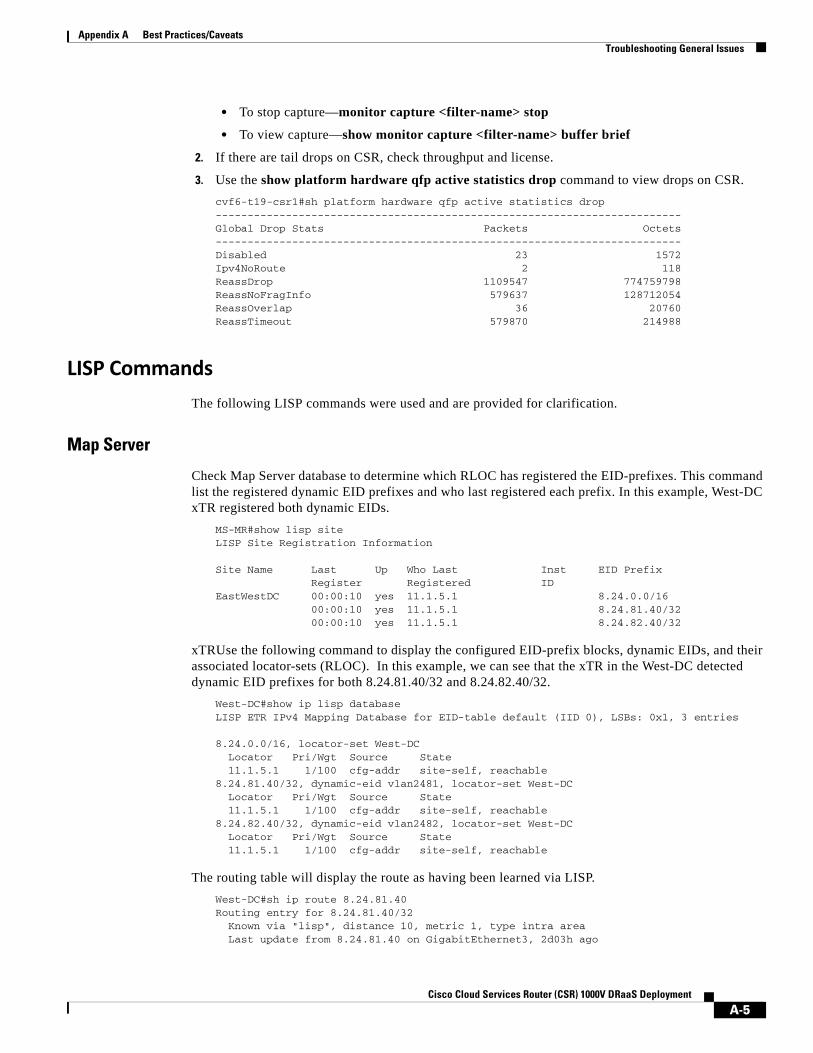
Appendix A Best Practices/Caveats Troubleshooting General Issues
• To stop capture—monitor capture <filter-name> stop
• To view capture—show monitor capture <filter-name> buffer brief
2. If there are tail drops on CSR, check throughput and license.
3. Use the show platform hardware qfp active statistics drop command to view drops on CSR.
cvf6-t19-csr1#sh platform hardware qfp active statistics drop -------------------------------------------------------------------------Global Drop Stats Packets Octets -------------------------------------------------------------------------Disabled 23 1572 Ipv4NoRoute 2 118 ReassDrop 1109547 774759798 ReassNoFragInfo 579637 128712054 ReassOverlap 36 20760 ReassTimeout 579870 214988
LISP Commands
The following LISP commands were used and are provided for clarification.
Map Server
Check Map Server database to determine which RLOC has registered the EID-prefixes. This command list the registered dynamic EID prefixes and who last registered each prefix. In this example, West-DC xTR registered both dynamic EIDs.
MS-MR#show lisp site LISP Site Registration Information
Site Name Last Up Who Last Inst EID Prefix Register Registered ID EastWestDC 00:00:10 yes 11.1.5.1 8.24.0.0/16 00:00:10 yes 11.1.5.1 8.24.81.40/32 00:00:10 yes 11.1.5.1 8.24.82.40/32
xTRUse the following command to display the configured EID-prefix blocks, dynamic EIDs, and their associated locator-sets (RLOC). In this example, we can see that the xTR in the West-DC detected dynamic EID prefixes for both 8.24.81.40/32 and 8.24.82.40/32.
West-DC#show ip lisp database LISP ETR IPv4 Mapping Database for EID-table default (IID 0), LSBs: 0x1, 3 entries
8.24.0.0/16, locator-set West-DC Locator Pri/Wgt Source State 11.1.5.1 1/100 cfg-addr site-self, reachable8.24.81.40/32, dynamic-eid vlan2481, locator-set West-DC Locator Pri/Wgt Source State 11.1.5.1 1/100 cfg-addr site-self, reachable8.24.82.40/32, dynamic-eid vlan2482, locator-set West-DC Locator Pri/Wgt Source State 11.1.5.1 1/100 cfg-addr site-self, reachable
The routing table will display the route as having been learned via LISP.
West-DC#sh ip route 8.24.81.40Routing entry for 8.24.81.40/32 Known via "lisp", distance 10, metric 1, type intra area Last update from 8.24.81.40 on GigabitEthernet3, 2d03h ago
A-5Cisco Cloud Services Router (CSR) 1000V DRaaS Deployment

Appendix A Best Practices/Caveats Troubleshooting General Issues
Routing Descriptor Blocks: * 8.24.81.40, from 0.0.0.0, 2d03h ago, via GigabitEthernet3 Route metric is 1, traffic share count is 1
PxTR
Ping the dynamic EID IP address from a device located behind the PxTR. Verify that an EID to RLOC entry exist in the local PxTR map-cache for the dynamic EID prefix.
pxtr#sh ip lisp map-cache LISP IPv4 Mapping Cache for EID-table default (IID 0), 3 entries
8.24.0.0/16, uptime: 5d20h, expires: never, via static send map-request Negative cache entry, action: send-map-request8.24.81.40/32, uptime: 23:00:27, expires: 00:59:33, via map-reply, complete Locator Uptime State Pri/Wgt 11.1.5.1 23:00:27 up 1/1008.24.82.40/32, uptime: 00:00:01, expires: 23:59:58, via map-reply, complete Locator Uptime State Pri/Wgt 11.1.5.1 00:00:01 up 1/100
Packets from non-LISP sites to LISP EIDs will be LISP encapsulated. The CEF next hop should be the virtual interface LISP0 which is where LISP encapsulation happens on the PxTR.
pxtr#sh ip cef 8.24.81.408.24.81.40/32 nexthop 11.1.5.1 LISP0
A-6Cisco Cloud Services Router (CSR) 1000V DRaaS Deployment
Cisco
A
P P E N D I X B CSR ConfigurationsCSR configurations for DRaaS System Enterprise (ENT) to Service Provider (SP) and vPC to vPC configurations follow:
• Enterprise to Service Provider Configurations, page B-1
– ENT-t19-CSR1 Configuration, page B-1
– SP-t19-CSR1 Configuration, page B-6
• vPC to vPC Configurations, page B-10
– West-DC xTR Configuration, page B-10
– East-DC xTR Configuration, page B-16
– PxTR Configuration, page B-21
Enterprise to Service Provider ConfigurationsThe following System Enterprise (ENT) to Service Provider (SP) configurations are provided:
• ENT-t19-CSR1 Configuration, page B-1
• SP-t19-CSR1 Configuration, page B-6
ENT-t19-CSR1 Configurationversion 15.3service timestamps debug datetime msecservice timestamps log datetime msecservice internalno platform punt-keepalive disable-kernel-coreplatform console virtual!hostname ENT-t19-csr1!boot-start-markerboot-end-marker!!vrf definition Mgmt-intf ! address-family ipv4 exit-address-family !
B-1 Virtual Multiservice Data Center (VMDC) 3.0
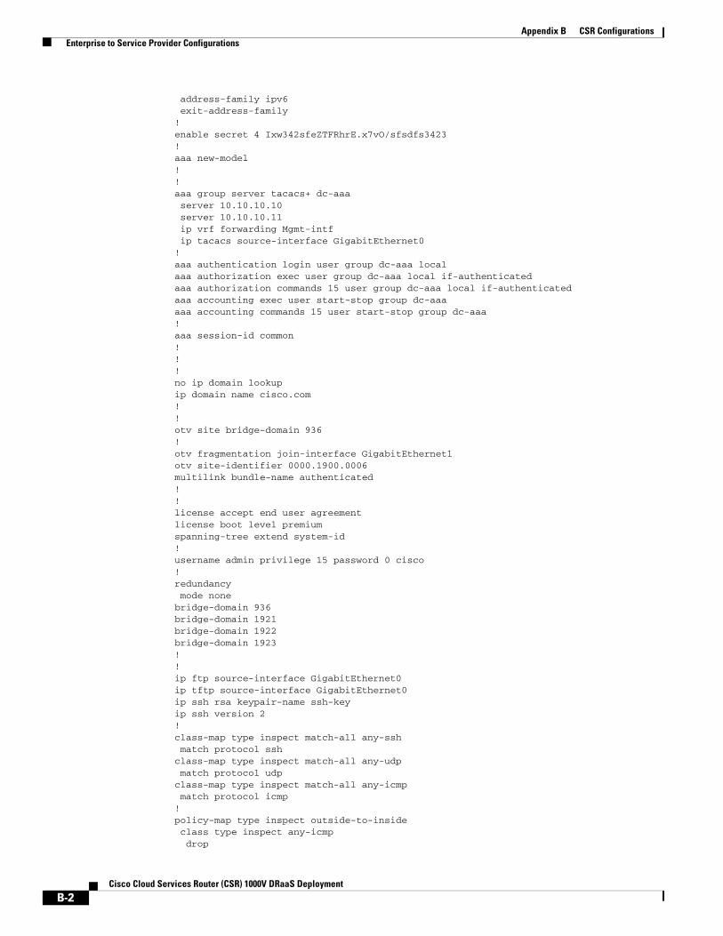
Appendix B CSR Configurations Enterprise to Service Provider Configurations
address-family ipv6 exit-address-family!enable secret 4 Ixw342sfeZTFRhrE.x7vO/sfsdfs3423!aaa new-model!!aaa group server tacacs+ dc-aaa server 10.10.10.10 server 10.10.10.11 ip vrf forwarding Mgmt-intf ip tacacs source-interface GigabitEthernet0!aaa authentication login user group dc-aaa localaaa authorization exec user group dc-aaa local if-authenticated aaa authorization commands 15 user group dc-aaa local if-authenticated aaa accounting exec user start-stop group dc-aaaaaa accounting commands 15 user start-stop group dc-aaa!aaa session-id common!!!no ip domain lookupip domain name cisco.com!!otv site bridge-domain 936!otv fragmentation join-interface GigabitEthernet1otv site-identifier 0000.1900.0006multilink bundle-name authenticated!!license accept end user agreementlicense boot level premiumspanning-tree extend system-id!username admin privilege 15 password 0 cisco!redundancy mode nonebridge-domain 936 bridge-domain 1921 bridge-domain 1922 bridge-domain 1923 !!ip ftp source-interface GigabitEthernet0ip tftp source-interface GigabitEthernet0ip ssh rsa keypair-name ssh-keyip ssh version 2!class-map type inspect match-all any-ssh match protocol sshclass-map type inspect match-all any-udp match protocol udpclass-map type inspect match-all any-icmp match protocol icmp!policy-map type inspect outside-to-inside class type inspect any-icmp drop
B-2Cisco Cloud Services Router (CSR) 1000V DRaaS Deployment
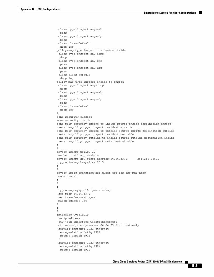
Appendix B CSR Configurations Enterprise to Service Provider Configurations
class type inspect any-ssh pass class type inspect any-udp pass class class-default drop logpolicy-map type inspect inside-to-outside class type inspect any-icmp drop class type inspect any-ssh pass class type inspect any-udp pass class class-default drop logpolicy-map type inspect inside-to-inside class type inspect any-icmp drop class type inspect any-ssh pass class type inspect any-udp pass class class-default drop log!zone security outsidezone security insidezone-pair security inside-to-inside source inside destination inside service-policy type inspect inside-to-insidezone-pair security inside-to-outside source inside destination outside service-policy type inspect inside-to-outsidezone-pair security outside-to-inside source outside destination inside service-policy type inspect outside-to-inside! !crypto isakmp policy 10 authentication pre-sharecrypto isakmp key cisco address 86.86.33.8 255.255.255.0crypto isakmp keepalive 20 5!! crypto ipsec transform-set myset esp-aes esp-md5-hmac mode tunnel!!!crypto map myvpn 10 ipsec-isakmp set peer 86.86.33.8 set transform-set myset match address 186!!!interface Overlay19 no ip address otv join-interface GigabitEthernet1 otv use-adjacency-server 86.86.33.8 unicast-only service instance 1921 ethernet encapsulation dot1q 1921 bridge-domain 1921 ! service instance 1922 ethernet encapsulation dot1q 1922 bridge-domain 1922
B-3Cisco Cloud Services Router (CSR) 1000V DRaaS Deployment

Appendix B CSR Configurations Enterprise to Service Provider Configurations
! service instance 1923 ethernet encapsulation dot1q 1923 bridge-domain 1923 !!interface GigabitEthernet1 description CVF6 Gold EP Join Interface1 ip address 86.68.33.6 255.255.255.0 load-interval 30 negotiation auto! interface GigabitEthernet2 description CVF6 Silver 1921 GW no ip address load-interval 30 negotiation auto service instance 936 ethernet encapsulation untagged bridge-domain 936 ! service instance 1921 ethernet encapsulation dot1q 1921 bridge-domain 1921 ! service instance 1922 ethernet encapsulation dot1q 1922 bridge-domain 1922 ! service instance 1923 ethernet encapsulation dot1q 1923 bridge-domain 1923 !!interface GigabitEthernet7 description CVF6 Silver 1921 GW ip address 86.19.21.1 255.255.255.0 load-interval 30 negotiation auto!interface GigabitEthernet8 description CVF6 Silver 1922 GW ip address 86.19.22.1 255.255.255.0 load-interval 30 negotiation auto!interface GigabitEthernet9 description CVF6 Silver 1923 GW ip address 86.19.23.1 255.255.255.0 load-interval 30 negotiation auto!interface GigabitEthernet0 vrf forwarding Mgmt-intf ip address 10.10.10.109 255.255.255.0 negotiation auto!router bgp 65062 bgp log-neighbor-changes network 86.19.21.0 mask 255.255.255.0 network 86.19.22.0 mask 255.255.255.0 network 86.19.23.0 mask 255.255.255.0 neighbor 6.101.100.26 remote-as 109 neighbor 6.101.100.26 ebgp-multihop 10
B-4Cisco Cloud Services Router (CSR) 1000V DRaaS Deployment
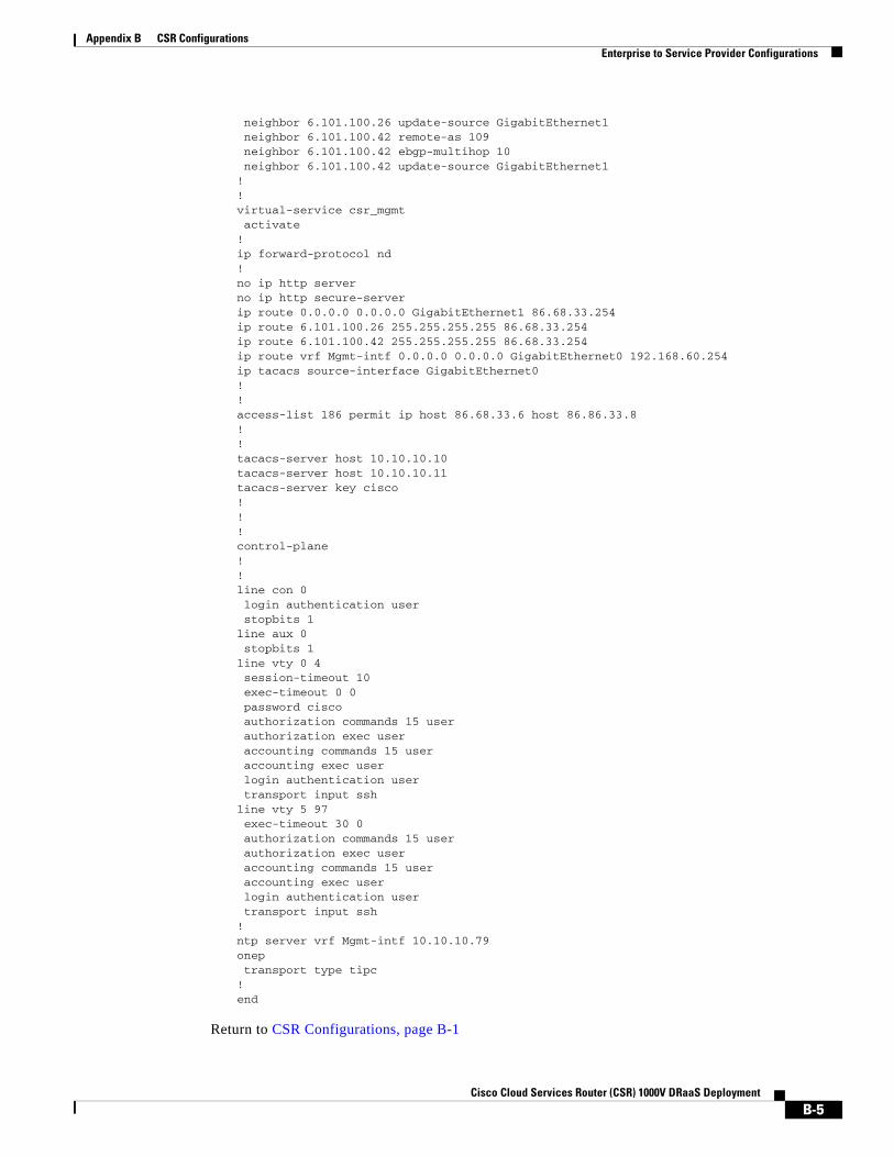
Appendix B CSR Configurations Enterprise to Service Provider Configurations
neighbor 6.101.100.26 update-source GigabitEthernet1 neighbor 6.101.100.42 remote-as 109 neighbor 6.101.100.42 ebgp-multihop 10 neighbor 6.101.100.42 update-source GigabitEthernet1! !virtual-service csr_mgmt activate!ip forward-protocol nd!no ip http serverno ip http secure-serverip route 0.0.0.0 0.0.0.0 GigabitEthernet1 86.68.33.254ip route 6.101.100.26 255.255.255.255 86.68.33.254ip route 6.101.100.42 255.255.255.255 86.68.33.254ip route vrf Mgmt-intf 0.0.0.0 0.0.0.0 GigabitEthernet0 192.168.60.254ip tacacs source-interface GigabitEthernet0!!access-list 186 permit ip host 86.68.33.6 host 86.86.33.8!!tacacs-server host 10.10.10.10tacacs-server host 10.10.10.11tacacs-server key cisco!!!control-plane!!line con 0 login authentication user stopbits 1line aux 0 stopbits 1line vty 0 4 session-timeout 10 exec-timeout 0 0 password cisco authorization commands 15 user authorization exec user accounting commands 15 user accounting exec user login authentication user transport input sshline vty 5 97 exec-timeout 30 0 authorization commands 15 user authorization exec user accounting commands 15 user accounting exec user login authentication user transport input ssh!ntp server vrf Mgmt-intf 10.10.10.79onep transport type tipc!end
Return to CSR Configurations, page B-1
B-5Cisco Cloud Services Router (CSR) 1000V DRaaS Deployment
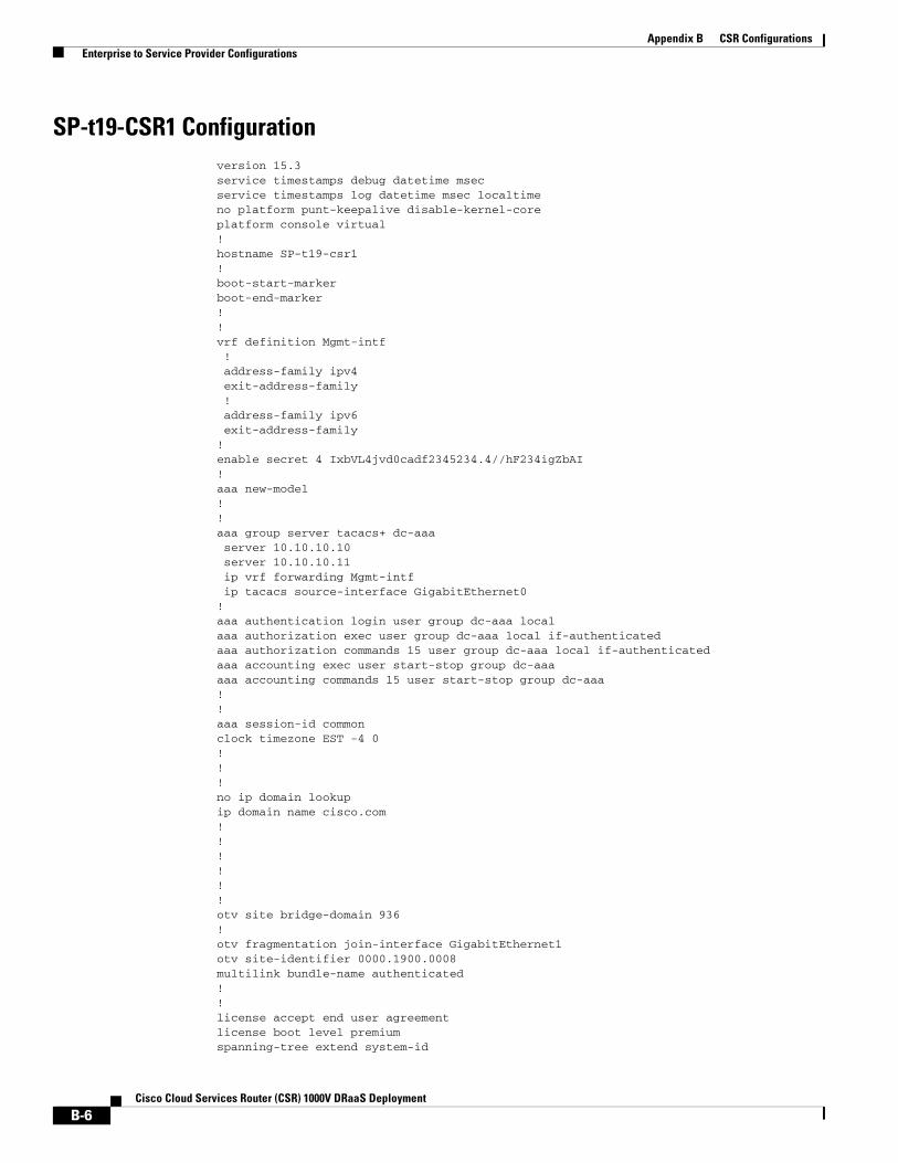
Appendix B CSR Configurations Enterprise to Service Provider Configurations
SP-t19-CSR1 Configurationversion 15.3service timestamps debug datetime msecservice timestamps log datetime msec localtimeno platform punt-keepalive disable-kernel-coreplatform console virtual!hostname SP-t19-csr1!boot-start-markerboot-end-marker!!vrf definition Mgmt-intf ! address-family ipv4 exit-address-family ! address-family ipv6 exit-address-family!enable secret 4 IxbVL4jvd0cadf2345234.4//hF234igZbAI!aaa new-model!!aaa group server tacacs+ dc-aaa server 10.10.10.10 server 10.10.10.11 ip vrf forwarding Mgmt-intf ip tacacs source-interface GigabitEthernet0!aaa authentication login user group dc-aaa localaaa authorization exec user group dc-aaa local if-authenticated aaa authorization commands 15 user group dc-aaa local if-authenticated aaa accounting exec user start-stop group dc-aaaaaa accounting commands 15 user start-stop group dc-aaa!!aaa session-id commonclock timezone EST -4 0!!!no ip domain lookupip domain name cisco.com! !!!!!otv site bridge-domain 936!otv fragmentation join-interface GigabitEthernet1otv site-identifier 0000.1900.0008multilink bundle-name authenticated!!license accept end user agreementlicense boot level premiumspanning-tree extend system-id
B-6Cisco Cloud Services Router (CSR) 1000V DRaaS Deployment
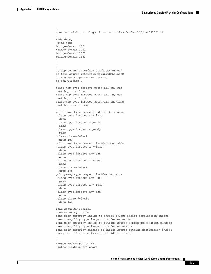
Appendix B CSR Configurations Enterprise to Service Provider Configurations
!username admin privilege 15 secret 4 23aadfsdfwer34//safd43dfZbAI!redundancy mode nonebridge-domain 936 bridge-domain 1921 bridge-domain 1922 bridge-domain 1923 !!!ip ftp source-interface GigabitEthernet0ip tftp source-interface GigabitEthernet0ip ssh rsa keypair-name ssh-keyip ssh version 2!class-map type inspect match-all any-ssh match protocol sshclass-map type inspect match-all any-udp match protocol udpclass-map type inspect match-all any-icmp match protocol icmp!policy-map type inspect outside-to-inside class type inspect any-icmp drop class type inspect any-ssh pass class type inspect any-udp pass class class-default drop logpolicy-map type inspect inside-to-outside class type inspect any-icmp drop class type inspect any-ssh pass class type inspect any-udp pass class class-default drop logpolicy-map type inspect inside-to-inside class type inspect any-udp pass class type inspect any-icmp drop class type inspect any-ssh pass class class-default drop log! zone security outsidezone security insidezone-pair security inside-to-inside source inside destination inside service-policy type inspect inside-to-insidezone-pair security inside-to-outside source inside destination outside service-policy type inspect inside-to-outsidezone-pair security outside-to-inside source outside destination inside service-policy type inspect outside-to-inside! !crypto isakmp policy 10 authentication pre-share
B-7Cisco Cloud Services Router (CSR) 1000V DRaaS Deployment

Appendix B CSR Configurations Enterprise to Service Provider Configurations
crypto isakmp key cisco address 86.68.33.6 255.255.255.0!!crypto ipsec transform-set myset esp-aes esp-md5-hmac mode tunnel!! !crypto map myvpn 10 ipsec-isakmp set peer 86.68.33.6 set transform-set myset match address 186!!!!interface Overlay19 no ip address otv join-interface GigabitEthernet1 otv adjacency-server unicast-only service instance 1921 ethernet encapsulation dot1q 1921 bridge-domain 1921 ! service instance 1922 ethernet encapsulation dot1q 1922 bridge-domain 1922 ! service instance 1923 ethernet encapsulation dot1q 1923 bridge-domain 1923 !!interface GigabitEthernet1 description CVF6 Gold EP Join Interface1 ip address 86.86.33.8 255.255.255.0 load-interval 30 negotiation auto arp timeout 1500!interface GigabitEthernet2 description CVF8 Silver 1921 GW no ip address load-interval 30 negotiation auto service instance 936 ethernet encapsulation untagged bridge-domain 936 ! service instance 1921 ethernet encapsulation dot1q 1921 bridge-domain 1921 ! service instance 1922 ethernet encapsulation dot1q 1922 bridge-domain 1922 ! service instance 1923 ethernet encapsulation dot1q 1923 bridge-domain 1923 !! interface GigabitEthernet9 description CVF8 Silver 1921 GW
B-8Cisco Cloud Services Router (CSR) 1000V DRaaS Deployment
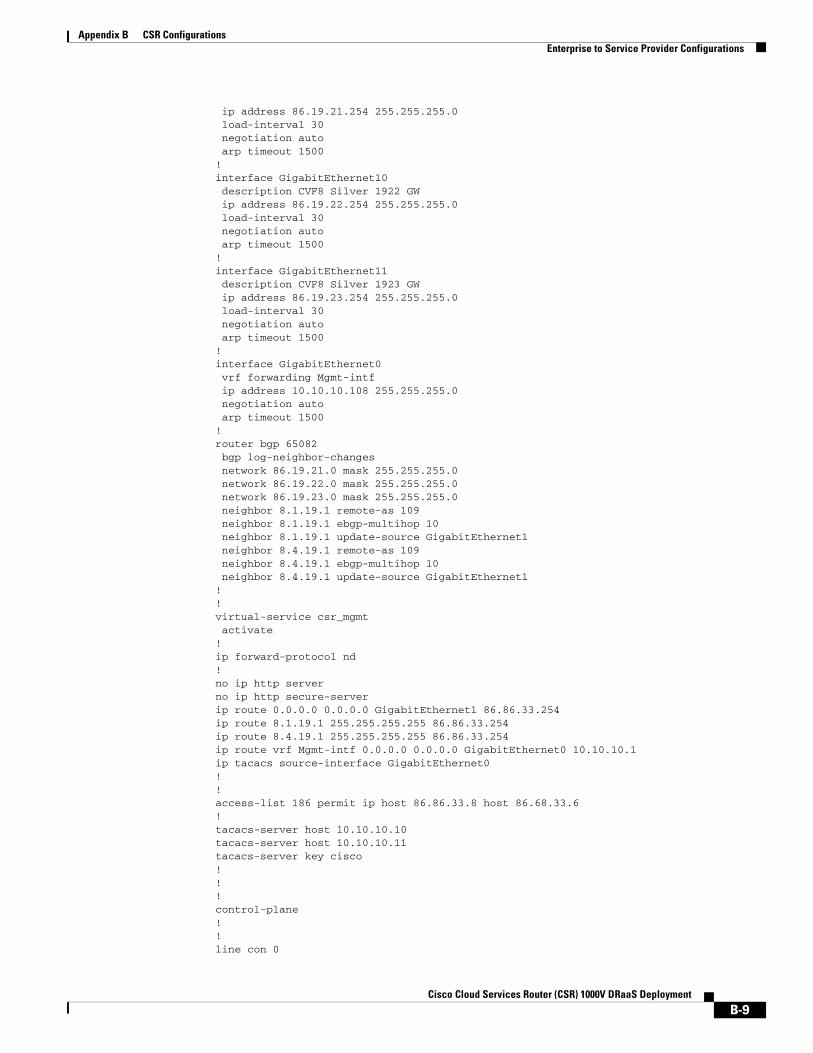
Appendix B CSR Configurations Enterprise to Service Provider Configurations
ip address 86.19.21.254 255.255.255.0 load-interval 30 negotiation auto arp timeout 1500!interface GigabitEthernet10 description CVF8 Silver 1922 GW ip address 86.19.22.254 255.255.255.0 load-interval 30 negotiation auto arp timeout 1500!interface GigabitEthernet11 description CVF8 Silver 1923 GW ip address 86.19.23.254 255.255.255.0 load-interval 30 negotiation auto arp timeout 1500!interface GigabitEthernet0 vrf forwarding Mgmt-intf ip address 10.10.10.108 255.255.255.0 negotiation auto arp timeout 1500!router bgp 65082 bgp log-neighbor-changes network 86.19.21.0 mask 255.255.255.0 network 86.19.22.0 mask 255.255.255.0 network 86.19.23.0 mask 255.255.255.0 neighbor 8.1.19.1 remote-as 109 neighbor 8.1.19.1 ebgp-multihop 10 neighbor 8.1.19.1 update-source GigabitEthernet1 neighbor 8.4.19.1 remote-as 109 neighbor 8.4.19.1 ebgp-multihop 10 neighbor 8.4.19.1 update-source GigabitEthernet1!!virtual-service csr_mgmt activate!ip forward-protocol nd!no ip http serverno ip http secure-serverip route 0.0.0.0 0.0.0.0 GigabitEthernet1 86.86.33.254ip route 8.1.19.1 255.255.255.255 86.86.33.254ip route 8.4.19.1 255.255.255.255 86.86.33.254ip route vrf Mgmt-intf 0.0.0.0 0.0.0.0 GigabitEthernet0 10.10.10.1ip tacacs source-interface GigabitEthernet0!!access-list 186 permit ip host 86.86.33.8 host 86.68.33.6!tacacs-server host 10.10.10.10tacacs-server host 10.10.10.11tacacs-server key cisco!!!control-plane!!line con 0
B-9Cisco Cloud Services Router (CSR) 1000V DRaaS Deployment
Appendix B CSR Configurations vPC to vPC Configurations
login authentication user stopbits 1line aux 0 stopbits 1line vty 0 4 session-timeout 10 exec-timeout 0 0 password cisco authorization commands 15 user authorization exec user accounting commands 15 user accounting exec user login authentication user transport input sshline vty 5 97 exec-timeout 30 0 authorization commands 15 user authorization exec user accounting commands 15 user accounting exec user login authentication user transport input ssh!ntp server vrf Mgmt-intf 10.10.10.79onep transport type tipc!end
Return to CSR Configurations, page B-1
vPC to vPC ConfigurationsThe following vPC to vPC configurations are provided:
• West-DC xTR Configuration, page B-10
• East-DC xTR Configuration, page B-16
• PxTR Configuration, page B-21
West-DC xTR Configurationservice timestamps debug datetime msecservice timestamps log datetime msecno platform punt-keepalive disable-kernel-coreplatform console virtual!hostname West-DC!boot-start-markerboot-end-marker!!vrf definition Mgmt-intf ! address-family ipv4 exit-address-family !
B-10Cisco Cloud Services Router (CSR) 1000V DRaaS Deployment
Appendix B CSR Configurations vPC to vPC Configurations
address-family ipv6 exit-address-family!vrf definition mgmt-netflow-export ! address-family ipv4 exit-address-family!!enable secret 4 IxbVL4jvd0ceZadf234dfaga.4//hF352igZbAI!aaa new-model!!aaa group server tacacs+ dc-aaa server 10.10.10.10 server 10.10.10.11 ip vrf forwarding Mgmt-intf ip tacacs source-interface GigabitEthernet0!aaa authentication login user group dc-aaa localaaa authorization exec user group dc-aaa local if-authenticated aaa authorization commands 15 user group dc-aaa local if-authenticated aaa accounting exec user start-stop group dc-aaaaaa accounting commands 15 user start-stop group dc-aaa!!!!!aaa session-id commonclock timezone EDT -5 0clock summer-time EDT recurring 1 Sun Mar 2:00 1 Sun Nov 2:00!
no ip domain lookupip domain name cisco.com!!otv site bridge-domain 939!otv fragmentation join-interface GigabitEthernet1otv site-identifier 0000.0000.0001otv isis Overlay1 lsp-mtu 1350!multilink bundle-name authenticated!!license accept end user agreementlicense boot level premium!mac access-list extended drop-hsrp-mac deny 0000.0c07.ac00 0000.0000.00ff host 0000.0000.0000 permit host 0000.0000.0000 host 0000.0000.0000spanning-tree extend system-id!username admin privilege 15 secret 4 IxbVL4jvd0ceZasd232ar2/bRlm.4//h354345bAI!redundancy mode nonebridge-domain 939 bridge-domain 2481
B-11Cisco Cloud Services Router (CSR) 1000V DRaaS Deployment
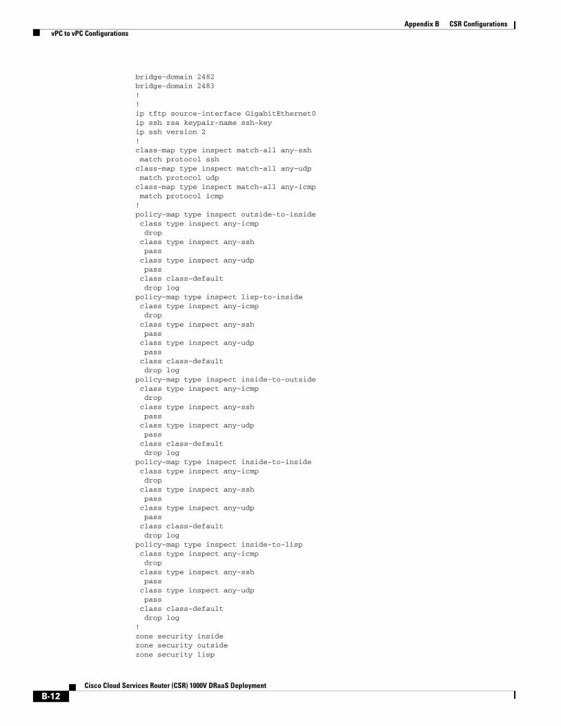
Appendix B CSR Configurations vPC to vPC Configurations
bridge-domain 2482 bridge-domain 2483 !!ip tftp source-interface GigabitEthernet0ip ssh rsa keypair-name ssh-keyip ssh version 2!class-map type inspect match-all any-ssh match protocol sshclass-map type inspect match-all any-udp match protocol udpclass-map type inspect match-all any-icmp match protocol icmp!policy-map type inspect outside-to-inside class type inspect any-icmp drop class type inspect any-ssh pass class type inspect any-udp pass class class-default drop logpolicy-map type inspect lisp-to-inside class type inspect any-icmp drop class type inspect any-ssh pass class type inspect any-udp pass class class-default drop logpolicy-map type inspect inside-to-outside class type inspect any-icmp drop class type inspect any-ssh pass class type inspect any-udp pass class class-default drop logpolicy-map type inspect inside-to-inside class type inspect any-icmp drop class type inspect any-ssh pass class type inspect any-udp pass class class-default drop logpolicy-map type inspect inside-to-lisp class type inspect any-icmp drop class type inspect any-ssh pass class type inspect any-udp pass class class-default drop log!zone security insidezone security outsidezone security lisp
B-12Cisco Cloud Services Router (CSR) 1000V DRaaS Deployment
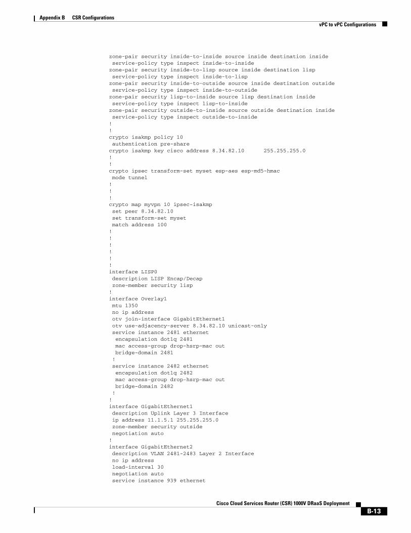
Appendix B CSR Configurations vPC to vPC Configurations
zone-pair security inside-to-inside source inside destination inside service-policy type inspect inside-to-insidezone-pair security inside-to-lisp source inside destination lisp service-policy type inspect inside-to-lispzone-pair security inside-to-outside source inside destination outside service-policy type inspect inside-to-outsidezone-pair security lisp-to-inside source lisp destination inside service-policy type inspect lisp-to-insidezone-pair security outside-to-inside source outside destination inside service-policy type inspect outside-to-inside! !crypto isakmp policy 10 authentication pre-sharecrypto isakmp key cisco address 8.34.82.10 255.255.255.0!!crypto ipsec transform-set myset esp-aes esp-md5-hmac mode tunnel!!!crypto map myvpn 10 ipsec-isakmp set peer 8.34.82.10 set transform-set myset match address 100!!!!! !interface LISP0 description LISP Encap/Decap zone-member security lisp!interface Overlay1 mtu 1350 no ip address otv join-interface GigabitEthernet1 otv use-adjacency-server 8.34.82.10 unicast-only service instance 2481 ethernet encapsulation dot1q 2481 mac access-group drop-hsrp-mac out bridge-domain 2481 ! service instance 2482 ethernet encapsulation dot1q 2482 mac access-group drop-hsrp-mac out bridge-domain 2482 !!interface GigabitEthernet1 description Uplink Layer 3 Interface ip address 11.1.5.1 255.255.255.0 zone-member security outside negotiation auto!interface GigabitEthernet2 description VLAN 2481-2483 Layer 2 Interface no ip address load-interval 30 negotiation auto service instance 939 ethernet
B-13Cisco Cloud Services Router (CSR) 1000V DRaaS Deployment

Appendix B CSR Configurations vPC to vPC Configurations
encapsulation dot1q 939 bridge-domain 939 ! service instance 2481 ethernet encapsulation dot1q 2481 bridge-domain 2481 ! service instance 2482 ethernet encapsulation dot1q 2482 bridge-domain 2482 !!interface GigabitEthernet3 description VLAN 2481 Layer 3 Interface ip address 8.24.81.2 255.255.255.0 ip access-group 2000 in no ip unreachables zone-member security inside standby 0 ip 8.24.81.1 load-interval 30 negotiation auto lisp mobility vlan2481 lisp extended-subnet-mode arp timeout 1500!interface GigabitEthernet4 description VLAN 2482 Layer 3 Interface ip address 8.24.82.2 255.255.255.0 ip access-group 2000 in no ip unreachables zone-member security inside standby 0 ip 8.24.82.1 load-interval 30 negotiation auto lisp mobility vlan2482 lisp extended-subnet-mode arp timeout 1500!interface GigabitEthernet0 vrf forwarding Mgmt-intf ip address 10.10.10.2 255.255.255.0 negotiation auto!router lisplocator-set West-DC 11.1.5.1 priority 1 weight 100 exit ! eid-table default instance-id 0 database-mapping 8.24.0.0/16 locator-set West-DC dynamic-eid vlan2481 database-mapping 8.24.81.0/24 locator-set West-DC exit ! dynamic-eid vlan2482 database-mapping 8.24.82.0/24 locator-set West-DC exit ! exit ! site EastWestDC authentication-key cisco eid-prefix 8.24.0.0/16 accept-more-specifics exit
B-14Cisco Cloud Services Router (CSR) 1000V DRaaS Deployment
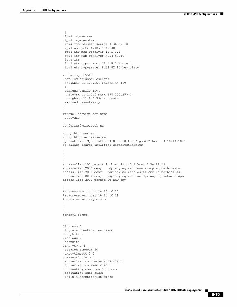
Appendix B CSR Configurations vPC to vPC Configurations
! ipv4 map-server ipv4 map-resolver ipv4 map-request-source 8.34.82.10 ipv4 use-petr 6.126.104.130 ipv4 itr map-resolver 11.1.5.1 ipv4 itr map-resolver 8.34.82.10 ipv4 itr ipv4 etr map-server 11.1.5.1 key cisco ipv4 etr map-server 8.34.82.10 key cisco!router bgp 65513 bgp log-neighbor-changes neighbor 11.1.5.254 remote-as 109 ! address-family ipv4 network 11.1.5.0 mask 255.255.255.0 neighbor 11.1.5.254 activate exit-address-family!!virtual-service csr_mgmt activate!ip forward-protocol nd!no ip http serverno ip http secure-serverip route vrf Mgmt-intf 0.0.0.0 0.0.0.0 GigabitEthernet0 10.10.10.1ip tacacs source-interface GigabitEthernet0!!!!access-list 100 permit ip host 11.1.5.1 host 8.34.82.10access-list 2000 deny udp any eq netbios-ns any eq netbios-nsaccess-list 2000 deny udp any eq netbios-ss any eq netbios-ssaccess-list 2000 deny udp any eq netbios-dgm any eq netbios-dgmaccess-list 2000 permit ip any any!!tacacs-server host 10.10.10.10tacacs-server host 10.10.10.11tacacs-server key cisco!!!control-plane!!line con 0 login authentication cisco stopbits 1line aux 0 stopbits 1line vty 0 4 session-timeout 10 exec-timeout 0 0 password cisco authorization commands 15 cisco authorization exec cisco accounting commands 15 cisco accounting exec cisco login authentication cisco
B-15Cisco Cloud Services Router (CSR) 1000V DRaaS Deployment

Appendix B CSR Configurations vPC to vPC Configurations
transport input sshline vty 5 97 exec-timeout 30 0 authorization commands 15 cisco authorization exec cisco accounting commands 15 cisco accounting exec cisco login authentication cisco transport input ssh!onep transport type tipc!end
Return to vPC to vPC Configurations, page B-10
Return to CSR Configurations, page B-1
East-DC xTR Configurationservice timestamps debug datetime msecservice timestamps log datetime msecno platform punt-keepalive disable-kernel-coreplatform console virtual!hostname West-DC!boot-start-markerboot-end-marker!!vrf definition Mgmt-intf ! address-family ipv4 exit-address-family ! address-family ipv6 exit-address-family!enable secret 4 IxbVL4jvd0ceadf23426/bRlm.4//hF234aZbAI!aaa new-model!!aaa group server tacacs+ dc-aaa server 10.10.10.10 server 10.10.10.11 ip vrf forwarding Mgmt-intf ip tacacs source-interface GigabitEthernet0!aaa authentication login user group dc-aaa localaaa authorization exec user group dc-aaa local if-authenticated aaa authorization commands 15 user group dc-aaa local if-authenticated aaa accounting exec user start-stop group dc-aaaaaa accounting commands 15 user start-stop group dc-aaa!!aaa session-id commonclock timezone EDT -5 0clock summer-time EDT recurring 1 Sun Mar 2:00 1 Sun Nov 2:00!
B-16Cisco Cloud Services Router (CSR) 1000V DRaaS Deployment
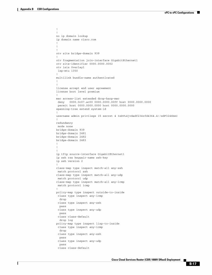
Appendix B CSR Configurations vPC to vPC Configurations
!!no ip domain lookupip domain name cisco.com!!!otv site bridge-domain 939!otv fragmentation join-interface GigabitEthernet1otv site-identifier 0000.0000.0002otv isis Overlay1 lsp-mtu 1350!multilink bundle-name authenticated!!license accept end user agreementlicense boot level premium!mac access-list extended drop-hsrp-mac deny 0000.0c07.ac00 0000.0000.00ff host 0000.0000.0000 permit host 0000.0000.0000 host 0000.0000.0000spanning-tree extend system-id!username admin privilege 15 secret 4 IxbVL4jvdadf234zfd4364.4//edF324ZbAI!redundancy mode nonebridge-domain 939 bridge-domain 2481 bridge-domain 2482 bridge-domain 2483 !!!ip tftp source-interface GigabitEthernet1ip ssh rsa keypair-name ssh-keyip ssh version 2!class-map type inspect match-all any-ssh match protocol sshclass-map type inspect match-all any-udp match protocol udpclass-map type inspect match-all any-icmp match protocol icmp! policy-map type inspect outside-to-inside class type inspect any-icmp drop class type inspect any-ssh pass class type inspect any-udp pass class class-default drop logpolicy-map type inspect lisp-to-inside class type inspect any-icmp drop class type inspect any-ssh pass class type inspect any-udp pass class class-default
B-17Cisco Cloud Services Router (CSR) 1000V DRaaS Deployment

Appendix B CSR Configurations vPC to vPC Configurations
drop logpolicy-map type inspect inside-to-outside class type inspect any-icmp drop class type inspect any-ssh pass class type inspect any-udp pass class class-default drop logpolicy-map type inspect inside-to-inside class type inspect any-icmp drop class type inspect any-ssh pass class type inspect any-udp pass class class-default drop logpolicy-map type inspect inside-to-lisp class type inspect any-icmp drop class type inspect any-ssh pass class type inspect any-udp pass class class-default drop log!zone security outsidezone security insidezone security lispzone-pair security inside-to-inside source inside destination inside service-policy type inspect inside-to-insidezone-pair security inside-to-lisp source inside destination lisp service-policy type inspect inside-to-lispzone-pair security inside-to-outside source inside destination outside service-policy type inspect inside-to-outsidezone-pair security lisp-to-inside source lisp destination inside service-policy type inspect lisp-to-insidezone-pair security outside-to-inside source outside destination inside service-policy type inspect outside-to-inside! !crypto isakmp policy 10 authentication pre-sharecrypto isakmp key cisco address 11.1.5.1 255.255.255.0!!crypto ipsec transform-set myset esp-aes esp-md5-hmac mode tunnel!!!crypto map myvpn 10 ipsec-isakmp set peer 11.1.5.1 set transform-set myset match address 100!!!interface LISP0description LISP Encap/Decap zone-member security lisp
B-18Cisco Cloud Services Router (CSR) 1000V DRaaS Deployment

Appendix B CSR Configurations vPC to vPC Configurations
!interface Overlay1 description CVF8 Gold SP Overlay Interface mtu 1350 no ip address otv join-interface GigabitEthernet1 otv adjacency-server unicast-only service instance 2481 ethernet encapsulation dot1q 2481 mac access-group drop-hsrp-mac out bridge-domain 2481 ! service instance 2482 ethernet encapsulation dot1q 2482 mac access-group drop-hsrp-mac out bridge-domain 2482 !!interface GigabitEthernet1 description Uplink Layer 3 Interface ip address 8.34.82.10 255.255.255.0 zone-member security outside negotiation auto!interface GigabitEthernet2 description VLAN 2481-2483 Layer 2 Interface no ip address load-interval 30 negotiation auto service instance 939 ethernet encapsulation dot1q 939 bridge-domain 939 ! service instance 2481 ethernet encapsulation dot1q 2481 bridge-domain 2481 ! service instance 2482 ethernet encapsulation dot1q 2482 bridge-domain 2482 !! interface GigabitEthernet3 description VLAN 2481 Layer 3 Interface ip address 8.24.81.3 255.255.255.0 ip access-group 2000 in no ip unreachables zone-member security inside standby 0 ip 8.24.81.1 load-interval 30 negotiation auto lisp mobility vlan2481 lisp extended-subnet-mode arp timeout 1500!interface GigabitEthernet4 description VLAN 2482 Layer 3 Interface ip address 8.24.82.3 255.255.255.0 ip access-group 2000 in no ip unreachables zone-member security inside standby 0 ip 8.24.82.1 load-interval 30 negotiation auto
B-19Cisco Cloud Services Router (CSR) 1000V DRaaS Deployment

Appendix B CSR Configurations vPC to vPC Configurations
lisp mobility vlan2482 lisp extended-subnet-mode arp timeout 1500!interface GigabitEthernet0 vrf forwarding Mgmt-intf ip address 10.10.10.3 255.255.255.0 negotiation auto!router lisp locator-set East-DC 8.34.82.10 priority 1 weight 100 exit ! eid-table default instance-id 0 database-mapping 8.24.0.0/16 locator-set East-DC dynamic-eid vlan2481 database-mapping 8.24.81.0/24 locator-set East-DC exit ! dynamic-eid vlan2482 database-mapping 8.24.82.0/24 locator-set East-DC exit ! exit ! site EastWestDC authentication-key cisco eid-prefix 8.24.0.0/16 accept-more-specifics exit ! ipv4 map-server ipv4 map-resolver ipv4 map-request-source 8.34.82.10 ipv4 use-petr 6.126.104.130 ipv4 itr map-resolver 11.1.5.1 ipv4 itr map-resolver 8.34.82.10 ipv4 itr ipv4 etr map-server 11.1.5.1 key cisco ipv4 etr map-server 8.34.82.10 key cisco ipv4 etr!router bgp 65508 bgp log-neighbor-changes neighbor 8.1.9.1 remote-as 109 neighbor 8.1.9.1 ebgp-multihop 10 neighbor 8.1.9.1 update-source GigabitEthernet1 neighbor 8.4.9.1 remote-as 109 neighbor 8.4.9.1 ebgp-multihop 10 neighbor 8.4.9.1 update-source GigabitEthernet1 ! address-family ipv4 neighbor 8.1.9.1 activate neighbor 8.4.9.1 activate exit-address-family!!virtual-service csr_mgmt activate!ip forward-protocol nd!no ip http serverno ip http secure-server
B-20Cisco Cloud Services Router (CSR) 1000V DRaaS Deployment
Appendix B CSR Configurations vPC to vPC Configurations
ip route 8.1.9.1 255.255.255.255 8.34.82.1ip route 8.4.9.1 255.255.255.255 8.34.82.1ip route vrf Mgmt-intf 0.0.0.0 0.0.0.0 GigabitEthernet0 10.10.10.1!!access-list 100 permit ip host 8.34.82.10 host 11.1.5.1access-list 2000 deny udp any eq netbios-ns any eq netbios-nsaccess-list 2000 deny udp any eq netbios-ss any eq netbios-ssaccess-list 2000 deny udp any eq netbios-dgm any eq netbios-dgmaccess-list 2000 permit ip any any!!!control-plane!!line con 0 login authentication cisco stopbits 1line aux 0 stopbits 1line vty 0 4 session-timeout 10 exec-timeout 0 0 password cisco authorization commands 15 cisco authorization exec cisco accounting commands 15 cisco accounting exec cisco login authentication cisco transport input sshline vty 5 97 exec-timeout 30 0 authorization commands 15 cisco authorization exec cisco accounting commands 15 cisco accounting exec cisco login authentication cisco transport input ssh!onep transport type tipc!end
Return to vPC to vPC Configurations, page B-10
Return to CSR Configurations, page B-1
PxTR Configurationservice timestamps debug datetime msecservice timestamps log datetime msecno platform punt-keepalive disable-kernel-coreplatform console virtual!hostname pxtr!boot-start-markerboot-end-marker!!
B-21Cisco Cloud Services Router (CSR) 1000V DRaaS Deployment
Appendix B CSR Configurations vPC to vPC Configurations
vrf definition Mgmt-intf ! address-family ipv4 exit-address-family ! address-family ipv6 exit-address-family!enable secret 4 IxbVL4jvd0ceZTFRhrE.x7vO/bRlm.4//hTrzigZbAI!aaa new-model!!aaa group server tacacs+ dc-aaa server 10.10.10.10 server 10.10.10.11 ip vrf forwarding Mgmt-intf ip tacacs source-interface GigabitEthernet0!aaa authentication login user group dc-aaa localaaa authorization exec user group dc-aaa local if-authenticated aaa authorization commands 15 user group dc-aaa local if-authenticated aaa accounting exec user start-stop group dc-aaaaaa accounting commands 15 user start-stop group dc-aaa!!!aaa session-id common!!!no ip domain lookupip domain name cisco.com!!multilink bundle-name authenticated!!license accept end user agreementlicense boot level premiumspanning-tree extend system-id!username admin privilege 15 secret 4 IxbVL4jvd0ceZTFRhrE.x7vO/bRlm.4//hTrzigZbAI!redundancy mode none!!!!ip tftp source-interface GigabitEthernet0ip ssh rsa keypair-name ssh-keyip ssh version 2!class-map type inspect match-all any-ssh match protocol sshclass-map type inspect match-all any-udp match protocol udpclass-map type inspect match-all any-icmp match protocol icmp!policy-map type inspect outside-to-insideclass type inspect any-icmp drop
B-22Cisco Cloud Services Router (CSR) 1000V DRaaS Deployment
Appendix B CSR Configurations vPC to vPC Configurations
class type inspect any-ssh pass class type inspect any-udp pass class class-default drop logpolicy-map type inspect lisp-to-inside class type inspect any-icmp drop class type inspect any-ssh pass class type inspect any-udp pass class class-default drop logpolicy-map type inspect inside-to-outsideclass type inspect any-icmp drop class type inspect any-ssh pass class type inspect any-udp pass class class-default drop logpolicy-map type inspect inside-to-lispclass type inspect any-icmp drop class type inspect any-ssh pass class type inspect any-udp pass class class-default drop log!zone security outsidezone security insidezone security lispzone-pair security inside-to-lisp source inside destination lisp service-policy type inspect inside-to-lispzone-pair security inside-to-outside source inside destination outside service-policy type inspect inside-to-outsidezone-pair security lisp-to-inside source lisp destination inside service-policy type inspect lisp-to-insidezone-pair security outside-to-inside source outside destination inside service-policy type inspect outside-to-inside! !!!!interface LISP0 zone-member security lisp!interface GigabitEthernet1 description Uplink Layer 3 Interface ip address 6.126.104.130 255.255.255.192 zone-member security outside load-interval 30 negotiation auto!interface GigabitEthernet2 description NON-LISP Subnet ip address 3.3.3.1 255.255.255.0 zone-member security inside
B-23Cisco Cloud Services Router (CSR) 1000V DRaaS Deployment

Appendix B CSR Configurations vPC to vPC Configurations
load-interval 30 negotiation auto!interface GigabitEthernet0 vrf forwarding Mgmt-intf ip address 10.10.10.4 255.255.255.0 negotiation auto!router lisp eid-table default instance-id 0 map-cache 8.24.0.0/16 map-request exit ! ipv4 map-request-source 6.126.104.130 ipv4 map-cache-limit 100000 ipv4 proxy-etr ipv4 proxy-itr 6.126.104.130 ipv4 itr map-resolver 11.1.5.1 ipv4 itr map-resolver 8.34.82.10exit!router bgp 65506 bgp log-neighbor-changes neighbor 6.101.98.18 remote-as 109 neighbor 6.101.98.18 ebgp-multihop 10 neighbor 6.101.98.18 update-source GigabitEthernet1 neighbor 6.101.98.34 remote-as 109 neighbor 6.101.98.34 ebgp-multihop 10 neighbor 6.101.98.34 update-source GigabitEthernet1 ! address-family ipv4 neighbor 6.101.98.18 activate neighbor 6.101.98.34 activate exit-address-family!!virtual-service csr_mgmt activate!ip forward-protocol nd!no ip http serverno ip http secure-serverip route 0.0.0.0 0.0.0.0 6.126.104.135ip route 6.101.98.18 255.255.255.255 6.126.104.135ip route 6.101.98.34 255.255.255.255 6.126.104.135ip route vrf Mgmt-intf 0.0.0.0 0.0.0.0 GigabitEthernet0 10.10.10.1!!control-plane!!line con 0 login authentication cisco stopbits 1line aux 0 stopbits 1line vty 0 4 session-timeout 10 exec-timeout 0 0 password cisco authorization commands 15 cisco authorization exec cisco accounting commands 15 cisco
B-24Cisco Cloud Services Router (CSR) 1000V DRaaS Deployment

Appendix B CSR Configurations vPC to vPC Configurations
accounting exec cisco login authentication cisco transport input sshline vty 5 97 exec-timeout 30 0 authorization commands 15 cisco authorization exec cisco accounting commands 15 cisco accounting exec cisco login authentication cisco transport input ssh!onep transport type tipc!end
Return to vPC to vPC Configurations, page B-10
Return to CSR Configurations, page B-1
B-25Cisco Cloud Services Router (CSR) 1000V DRaaS Deployment
Appendix B CSR Configurations vPC to vPC Configurations
B-26Cisco Cloud Services Router (CSR) 1000V DRaaS Deployment
Cisco Cloud Serv
A
P P E N D I X C PackagingCisco CSR 1000V Packaging—The CSR 1000V is licensed based on feature set (Table C-1) and throughput (Table C-2) and can be purchased for a term of 1 or 3 years, or perpetually.
Table C-1 Server Resource Requirements per CSR 1000V License by Feature Set
Features Description
Standard Routing: RIP, BGP, EIGRP, OSPF, IS-IS, GRE, IPv6, VRF-Lite
Addressing: DHCP, DNS, NAT, 802.1Q VLAN, EVC
Basic Security: ACL, AAA, RADIUS, TACACS+
High Availability: HSRP, VRRP, GLBP
Management: SSH, Telnet, SNMP, Syslog, NetFlow, EEM
Advanced Standard features
Advanced Security: IPSec, Route-based VPNs (DMVPN, EasyVPN, FlexVPN), Zone-based Firewall
Premium Advanced features
MPLS: MPLS VPN, VRF, BFD
Application Experience: AppNav, WCCP, AVC, IP SLA
IP Mobility: LISP, OTV, VPLS, EoMPLS
Table C-2 Server Resource Requirements per CSR 1000V License by Throughput
Throughput Technology Package
Standard Advanced Premium
10 Mbps 1 vCPU, 2.5 GB RAM 1 vCPU, 2.5 GB RAM 1 vCPU, 2.5 GB RAM
50 Mbps 1 vCPU, 2.5 GB RAM 1 vCPU, 2.5 GB RAM 1 vCPU, 2.5 GB RAM
100 Mbps 1 vCPU, 2.5 GB RAM 1 vCPU, 2.5 GB RAM 1 vCPU, 2.5 GB RAM
250 Mbps 4 vCPU*, 4 GB RAM* 4 vCPU*, 4 GB RAM* 4 vCPU*, 4 GB RAM*
500 Mbps 4 vCPU*, 4 GB RAM*
1 Gbps 4 vCPU*, 4 GB RAM*
C-1ices Router (CSR) 1000V DRaaS Deployment

Appendix C Packaging
C-2Cisco Cloud Services Router (CSR) 1000V DRaaS Deployment