
Cis187 Switch 4 Intervlanrouting Mls Cef
87
CIS 187 Multilayer Switched Networks CCNP Switch Inter-VLAN Routing, Multilayer Switching and CEF Rick Graziani Cabrillo College [email protected] Spring 2010
-
Upload
vamsi-krishna -
Category
Documents
-
view
155 -
download
7
Transcript of Cis187 Switch 4 Intervlanrouting Mls Cef
CIS 187 Multilayer Switched NetworksCCNP Switch
Inter-VLAN Routing, Multilayer Switching and CEF
Rick Graziani
Cabrillo College
Spring 2010
Inter-VLAN Routing

3
Internetwork Communications
Can two hosts on different subnets communicate without a router? No
What would happen if a host tried to ping another host? They could not communicate.
Would it send an ARP Request? Why or why not? The host would not send an ARP Request because there is no
default-gateway.
C:>ping 172.16.30.100

4
Internetwork Communications
Then Destination MAC Address is that of the same device as the Destination IP Address. Check ARP cache for entry of Destination IP Address and its MAC Address.
If no entry, ARP Request Destination IP Address asking for MAC Address.
Then Destination MAC Address will be that of the Default Gateway. Check ARP cache for entry of Default Gateway’s IP Address and its MAC Address.
If no entry, ARP Request Default Gateway’s IP Address asking for MAC Address.

5
InterVLAN Routing
External RouterRouter(config)# inter fa 0/1Router(config-if) ip address 172.16.1.1 255.255.255.0Router(config)# inter fa 0/2Router(config-if) ip address 172.16.2.1 255.255.255.0Router(config)# inter fa 0/3Router(config-if) ip address 172.16.3.1 255.255.255.0
VLAN 1
VLAN 3
VLAN 2
VLANs 1, 2, 3
Trunk
VLAN 1
VLAN 2
VLAN 3
External Router
Router on a stick
Multilayer Switch Or Trunk

6
Configure Router On A Stick: 802.1Q Trunk Link
interface GigabitEthernet1/1 switchport mode trunk
interface GigabitEthernet5/0 no shutdown ! Does not show in config!interface GigabitEthernet5/0.2 description VLAN 2 encapsulation dot1Q 2 native ip address 172.16.1.2 255.255.255.0!interface GigabitEthernet5/0.10 description VLAN 10 encapsulation dot1Q 10 ip address 172.16.10.1 255.255.255.0!interface GigabitEthernet5/0.20 description VLAN 20 encapsulation dot1Q 20 ip address 172.16.20.1 255.255.255.0!interface GigabitEthernet5/0.30 description VLAN 30 encapsulation dot1Q 30 ip address 172.16.30.1 255.255.255.0!interface GigabitEthernet5/0.40 description VLAN 40 encapsulation dot1Q 40 ip address 172.16.40.1 255.255.255.0
172.16.10.100/24
172.16.20.100/24
Router on a stick is very simple to implement.

Multilayer Switches
8
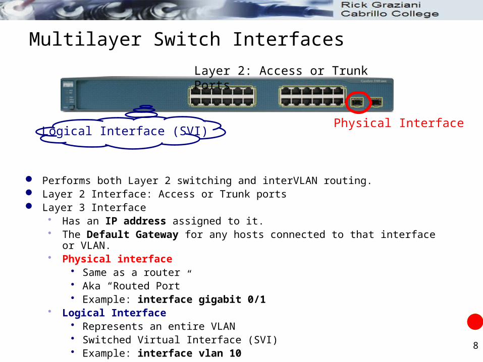
Multilayer Switch Interfaces
Performs both Layer 2 switching and interVLAN routing. Layer 2 Interface: Access or Trunk ports Layer 3 Interface
Has an IP address assigned to it. The Default Gateway for any hosts connected to that interface or VLAN. Physical interface
Same as a router Aka “Routed Port” Example: interface gigabit 0/1
Logical Interface Represents an entire VLAN Switched Virtual Interface (SVI) Example: interface vlan 10
Physical InterfaceLogical Interface (SVI)
Layer 2: Access or Trunk Ports

9
Multilayer Switch Interfaces
Layer 2 or Layer 3 Interface? Default on most Catalyst switches: Layer 2 Default on Catalyst 6500: Layer 3
Verify mode: Switch# show interface type mod/num switchport
Switchport: Think Layer 2 Enabled: Layer 2 Disabled: Layer 3
Physical Interface (L3)Logical Interface (SVI – L3)
Layer 2: Access or Trunk Ports
DLS1# show interface gig 0/2 switchport
Name: Gig0/2
Switchport: Enabled
<output omitted>

10
Multilayer Switch Interfaces
If in Layer 3 mode switchport interface command puts the port into Layer 2 mode.
DLS1# show interface gig 0/2 switchport
Name: Gig0/2
Switchport: Disabled
<output omitted>
DLS1# config t
DLS1(config)# interface gig 0/2
DLS1(config-if)# switchport
DLS1(config-if)# end
DLS1# show interface gig 0/2 switchport
Name: Gig0/2
Switchport: Enabled
<output omitted>
Layer 3
Layer 2
Converts interface to Layer 2

11
Layer 3 Port Configuration – Physical Interfaces
Physical switch ports can operate as Layer 3 interfaces using the interface command:Switch(config)# interface type mod/num
Switch(config-if)# no switchport
Switch(config-if)# ip address ip-address mask
DLS1(config)# interface gig 0/1
DLS1(config-if)# no switchport
DLS1(config-if)# ip address 192.168.1.1 255.255.255.252
DLS2(config)# interface gig 0/1
DLS2(config-if)# no switchport
DLS2(config-if)# ip address 192.168.1.2 255.255.255.252

12
Try it
What happens if you configure the IP address BEFORE issuing the no switchport command?
Download: PT-Topology-
SwitchBlock-MLS.pkt
Configure the appropriate interfaces in DLS1 and DLS2 as physical layer 3 addresses.
Note: Core has the first host addresses.

13
Verify by pinging neighbor interface.
DLS1(config)# interface gig 0/1
DLS1(config-if)# no switchport
DLS1(config-if)# ip address 192.168.1.1 255.255.255.252
DLS1(config-if)# no shutdown
DLS1(config)# interface fa 0/1
DLS1(config-if)# no switchport
DLS1(config-if)# ip address 192.168.1.5 255.255.255.252
DLS1(config-if)# no shutdown
DLS2(config)# interface gig 0/1
DLS2(config-if)# no switchport
DLS2(config-if)# ip address 192.168.1.2 255.255.255.252
DLS2(config-if)# no shutdown
DLS2(config)# interface fa 0/2
DLS2(config-if)# no switchport
DLS2(config-if)# ip address 192.168.1.10 255.255.255.252
DLS2(config-if)# no shutdown

14
If several interfaces are bundled together using EtherChannel the IP address is assigned to the port-channel interface, not the individual physical links.
To configure Layer 3 EtherChannels,: First you must create the port-channel logical interface Then you add the Ethernet ports into the port-channel
SwitchA(config)# interface port-channel 5
SwitchA(config-if)# no switchport
SwitchA(config-if)# ip address 192.168.2.1 255.255.255.252
SwitchB(config)# interface port-channel 5
SwitchB(config-if)# no switchport
SwitchB(config-if)# ip address 192.168.2.2 255.255.255.252
Physical Interfaces and EtherChannel
192.168.2.1 192.168.2.2

15
What about EtherChannel Interfaces?
First you must create the port-channel logical interface Then you add the Ethernet ports into the port-channel Using LACP in this example. Remember, the channel-group number is associated with the port-channel interface.
SwitchA(config)# interface port-channel 5
SwitchA(config-if)# no switchport
SwitchA(config-if)# ip address 192.168.2.1 255.255.255.252
SwitchA(config)# interface range fa 0/11 - 12
SwitchA(config-if-range)# no ip address
SwitchA(config-if-range)# no switchport
SwitchA(config-if-range)# channel-group 5 mode active
SwitchB(config)# interface port-channel 5
SwitchB(config-if)# no switchport
SwitchB(config-if)# ip address 192.168.2.2 255.255.255.252
SwitchB(config)# interface range fa 0/11 - 12
SwitchB(config-if-range)# no ip address
SwitchB(config-if-range)# no switchport
SwitchB(config-if-range)# channel-group 5 mode active
Port-channel 5 Port-channel 5
Fa 0/11 Fa 0/11
Fa 0/12 Fa 0/12192.168.2.1 192.168.2.2

16
SwitchA# show ip inter brief
Port-channel5 192.168.1.1 YES manual up up
SwitchA# ping 192.168.1.2
!!!!!
SwitchA# show ether summ
Flags: D - down P - in port-channel
I - stand-alone s - suspended
H - Hot-standby (LACP only)
R - Layer3 S - Layer2
U - in use f - failed to allocate aggregator
u - unsuitable for bundling
w - waiting to be aggregated
d - default port
Number of channel-groups in use: 1
Number of aggregators: 1
Group Port-channel Protocol Ports
------+-------------+-----------+-----------------------------------------------
5 Po5(RU) LACP Fa0/11(P) Fa0/12(P)
DLS1#
192.168.2.1 192.168.2.2

17
SVI Interfaces- Logical Interfaces
Layer 3 functionality can also be enabled for an entire VLAN. The IP address is assigned to the logical interface – the VLAN. This is needed when routing is required between VLANs. SVI (Switched Virtual Interface)
No physical connection VLANs must be created before the SVI can be used. The IP address associated of the VLAN interface is the default gateway of
the workstation.
Switch(config)# vlan vlan-number
Switch(config-vlan)# name vlan-name
SwitchA(config)# interface vlan vlan-number
SwitchA(config-if)# ip address ip-address mask
SwitchA(config-if)# no shutdown

18
Remember our Switch Block…
We created the SVI interfaces! I will have you recreate some of them…

19
Creating VLANs
DLS1
vlan 2
name NATIVE
vlan 10
name Engineering
vlan 11
name IT
vlan 20
name Sales
vlan 21
name Administration
vlan 99
name ManagementVLAN
vlan 222
name GarbageVLAN
DLS1: Create and name the user VLANs: 10, 11, 20 and 21.
DLS1: Create and name a Management VLAN (used to telnet into switches)
DLS1: Create and name a NATIVE VLAN other than VLAN 1 (default)
DLS1: Create and name a Garbage VLAN (assigned to all unused ports.) All ports that are not used (trunks and
access) will be assigned as an access port to this VLAN.

20
Management VLAN
On each switch
Switch(config)# inter vlan 99
Switch(config-if)# description Management VLAN
Switch(config-if)# ip address 172.16.99.x 255.255.255.0
Switch(config-if)# no shutdown
For each device in the network we configured it to be a member of the management VLAN.
21
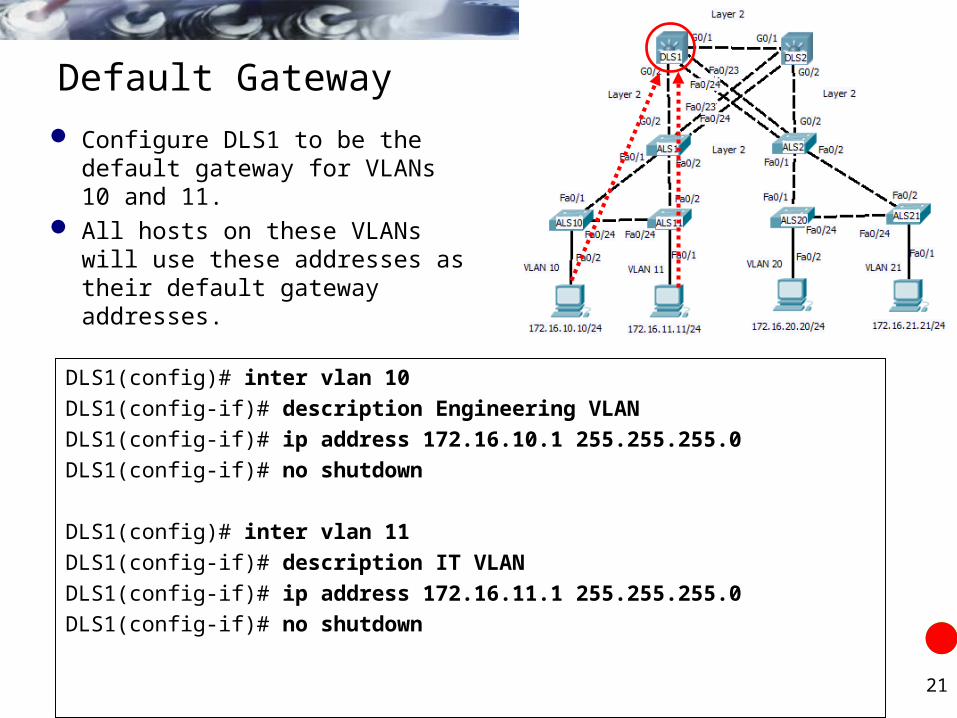
Default Gateway
DLS1(config)# inter vlan 10
DLS1(config-if)# description Engineering VLAN
DLS1(config-if)# ip address 172.16.10.1 255.255.255.0
DLS1(config-if)# no shutdown
DLS1(config)# inter vlan 11
DLS1(config-if)# description IT VLAN
DLS1(config-if)# ip address 172.16.11.1 255.255.255.0
DLS1(config-if)# no shutdown
Configure DLS1 to be the default gateway for VLANs 10 and 11.
All hosts on these VLANs will use these addresses as their default gateway addresses.

22
Default Gateway
Configure DLS2 to be the default gateway for VLANs 20 and 21.
All hosts on these VLANs will use these addresses as their default gateway addresses.
DLS2(config)# inter vlan 20
DLS2(config-if)# description Sales VLAN
DLS2(config-if)# ip address 172.16.20.1 255.255.255.0
DLS2(config-if)# no shut
DLS2(config)# inter vlan 21
DLS2(config-if)# description Administration VLAN
DLS2(config-if)# ip address 172.16.21.1 255.255.255.0
DLS2(config-if)# no shut

23
Verifying
DLS1#show ip inter brief
Interface IP-Address OK? Method Status Protocol
FastEthernet0/1 192.168.4.6 YES manual up up
GigabitEthernet0/1 192.168.1.1 YES manual up up
Vlan10 172.16.10.1 YES manual up up
Vlan11 172.16.11.1 YES manual up up
Port-channel 1 unassigned YES manual up up
DLS1#
Verify IP addresses

24
Configuring a Routed Port
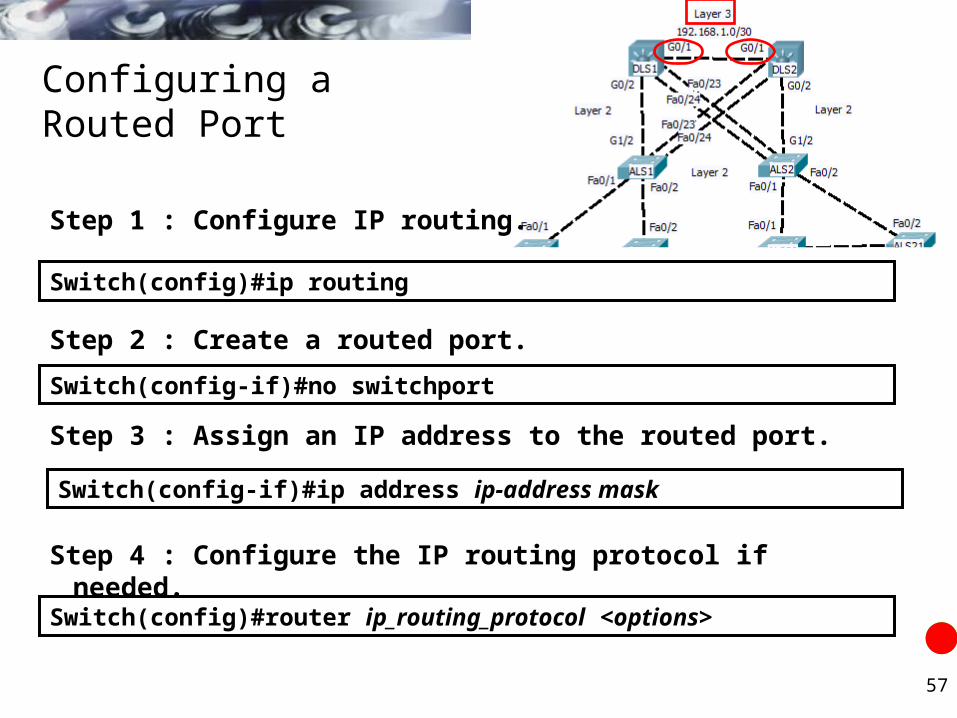
Switch(config)#ip routing
Step 1 : Configure IP routing.
Switch(config)#router ip_routing_protocol <options>
Step 4 : Configure the IP routing protocol if needed.
Switch(config-if)#no switchport
Step 2 : Create a routed port.
Switch(config-if)#ip address ip-address mask
Step 3 : Assign an IP address to the routed port.

25
Configuring Inter-VLAN Routing Through an SVI
Switch(config)#ip routing
Step 1 : Configure IP routing.
Switch(config)#router ip_routing_protocol <options>
Step 4 : Configure the IP routing protocol if needed.
Switch(config)#interface vlan vlan-id
Step 2 : Create an SVI interface.
Switch(config-if)#ip address ip-address mask
Step 3 : Assign an IP address to the SVI.

26
Enabling CEF (Cisco Express Forwarding)
Switch(config-if)#ip route-cache cef
The commands required to enable CEF are platform dependent:
On the Cisco Catalyst 3550 switch (enabled by default)
We are going to discuss CEF and Multilayer Switching next. By default the 3550/3560 has CEF enabled by default. The only thing left is to configure routing on the two distribution layer
switches.

27
Routing
Enable routing on DLS1 and DLS2.
Configure EIGRP DLS1 and DLS2. Turn off auto-summarization
DLS1(config)# ip routing
DLS1(config)# router eigrp 1
DLS1(config-router)# network 172.16.0.0
DLS1(config-router)# network 192.168.1.0
DLS1(config-router)# no auto-summary
DLS2(config)# ip routing
DLS2(config)# router eigrp 1
DLS2(config-router)# network 172.16.0.0
DLS2(config-router)# network 192.168.1.0
DLS2(config-router)# no auto-summary

28
Verifying
DLS1#show ip route
1.0.0.0/24 is subnetted, 1 subnets
D 1.1.1.0 [90/25628160] via 192.168.1.5, 00:00:07, FastEthernet0/1
172.16.0.0/24 is subnetted, 5 subnets
C 172.16.10.0 is directly connected, Vlan10
C 172.16.11.0 is directly connected, Vlan11
D 172.16.20.0 [90/25625856] via 192.168.1.2, 01:29:41, GigabitEthernet0/1
D 172.16.21.0 [90/25625856] via 192.168.1.2, 01:29:41, GigabitEthernet0/1
C 172.16.99.0 is directly connected, Vlan99
192.168.1.0/30 is subnetted, 3 subnets
C 192.168.1.0 is directly connected, GigabitEthernet0/1
C 192.168.1.4 is directly connected, FastEthernet0/1
D 192.168.1.8 [90/28416] via 192.168.1.2, 01:17:18, GigabitEthernet0/1
DLS1#
Verify routing
Core Network
DLS2 Networks (VLANs)
Network between DLS2 and Core

Traditional and CEF Based Multilayer Switching

30
Multilayer Switching
Multilayer switching - ability of a Catalyst switch to support switching and routing of packets in hardware. Optional support for Layers 4 through 7 switching in hardware as well. A route processor (or Layer 3 engine) must download software-based
routing, switching, access lists, QoS, and other information to the hardware for packet processing.
Traditional MLS CEF-Based MLS

31
Traditional and CEF-based MLS
Cisco Catalyst switches use either: Traditional multilayer switching (traditional MLS)
A legacy feature Cisco Express Forwarding (CEF)-based MLS architecture.
All leading-edge Catalyst switches support CEF-based multilayer switching
Traditional MLS CEF-Based MLS

32
Traditional MLS
Dual effort between: Route Processor (RP) Switching Engine (SE)
Traditional MLS: Route once, switch many Specialized Application-Specific Integrated Circuits (ASICs) perform Layer
2 rewrite operations of routed packets: Source MAC address Destination MAC address Cyclic redundancy check (CRC).
Because the source and destination MAC addresses change during Layer 3 rewrites, the switch must recalculate the CRC for these new MAC addresses.
RP
SE
33
Traditional MLS
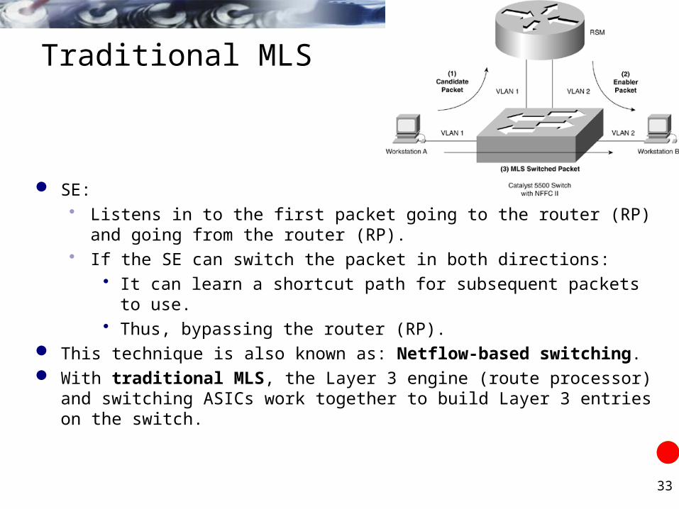
SE: Listens in to the first packet going to the router (RP) and going from the
router (RP). If the SE can switch the packet in both directions:
It can learn a shortcut path for subsequent packets to use. Thus, bypassing the router (RP).
This technique is also known as: Netflow-based switching. With traditional MLS, the Layer 3 engine (route processor) and switching
ASICs work together to build Layer 3 entries on the switch.

34
Traditional MLS
Hardware consists of: Independent RP NetFlow-capable SE
Netflow switching (or route cache switching) performed on Cisco hardware such as: Catalyst 6000 Supervisor 1/1a and Multilayer Switch Feature Card
(MSFC) Catalyst 550 with a Route Switch Module (RSM) Route Switch Feature Card (RSFC) External Router
MSFCRSM
RSFC

35
Traditional MLS
The switch forwards the first packet in any flow to the Layer 3 engine for processing using software switching/routing.
After the routing of the first packet in the flow, the Layer 3 engine programs the hardware-switching components for routing for subsequent packets.
dot1q Tag(inside Eth. Hdr)
Ethernet Header IP Header IP Data
VLAN 1
D-MAC= 00-00-0C-11-11-11
S-MAC= 00-AA-00-11-11-11
S-IP = 10.1.1.10
D-IP = 10.1.2.20
S-MAC= 00-AA-00-11-11-11

36
Workstation A sends a packet to workstation B, Workstation A sends the packet to its default gateway (which is the RSM).
Switch (MLS-SE) recognizes this packet as an MLS candidate packet because the destination MAC address matches the MAC address of the MLS router (MLS-RP).
As a result, the switch creates a candidate entry for this flow.
MLS-SE
MLS-RPMLS-RPThe Destination MAC Address is one of the router’s interfaces.There is not an existing flow, so I will flag this as a candidate packet.
Candidate Packet Info
Layer 3 Info S-IP 10.1.1.10 D-IP 10.1.2.20
Layer 2 Info S-MAC 00-AA-00-11-11-11 D-MAC 00-00-0C-11-11-11
dot1q Tag(inside Eth. Hdr)
Ethernet Header IP Header IP Data
VLAN 1
D-MAC= 00-00-0C-11-11-11
S-MAC= 00-AA-00-11-11-11
S-IP = 10.1.1.10
D-IP = 10.1.2.20

37
Next, the router accepts the packets from workstation A, rewrites the Layer 2 MAC addresses and CRC, and forwards the packet to workstation B.
The switch refers to the routed packet from the RSM as the enabler packet.
MLS-SE
MLS-RP
dot1q Tag(inside Eth. Hdr)
Ethernet Header IP Header IP Data
VLAN 2 D-MAC= 00-AA-00-22-22-22
S-MAC= 00-00-0C-22-22-22
S-IP = 10.1.1.10
D-IP = 10.1.2.20

38
MLS-SE recognizes various matches including CAM, details not included. Basically, the MLS-SE recognizes that the packet going out of VLAN 2 was the
same one that came in on VLAN 1. The switch, upon seeing both the candidate and enabler packets, creates an MLS entry
in hardware (MLS Cache) such that the switch rewrites and forwards all future packets matching this flow.
MLS-SE
MLS-RP
dot1q Tag(inside Eth. Hdr)
Ethernet Header IP Header IP Data
VLAN 2
D-MAC= 00-AA-00-22-22-22
S-MAC= 00-00-0C-22-22-22
S-IP = 10.1.1.10
D-IP = 10.1.2.20
Candidate Packet Info
Layer 3 Info S-IP 10.1.1.10 D-IP 10.1.2.20
Layer 2 Info S-MAC 00-AA-00-11-11-11 D-MAC 00-00-0C-11-11-11

39
As future packets from the “flow” arrive, the MLS-SE uses the destination IP address to look up the entry in the MLS cache.
Finding a match, rewrite engine modifies the necessary header information and forwards the frame (the packet is not forwarded to the router).
The rewrite operation modifies all the same fields initially modified by the router for the first packet, including the source MAC and destination MAC addresses.
MLS-SE
MLS-RPCandidate Packet Info
Layer 3 Info S-IP 10.1.1.10 D-IP 10.1.2.20
Layer 2 Info S-MAC 00-AA-00-11-11-11 D-MAC 00-00-0C-11-11-11
Dst IP Src IP Port Dst Port
Src Port
Dst MAC
Src MAC
VLAN Interface
10.1.2.20 10.1.1.10 TCP 23 1238 00-AA-00-22-22-22
00-00-0C-22-22-22
2 3/1
Future Packets
MLS Cache
Found match in MLS Cache, rewrite Ethernet
Header and send directly to Host B, forget the
router!

40
CEF-based MLS

41
CEF
CEF-based MLS forwarding model is used to: Download the control plane information (such as the access lists) to
the data plane (on the supervisor, port, or line card) for hardware switching of packets.
Control plane represents the Layer 3 engine (route processor) Data plane represents the hardware components such as ASICs used
by the switch for hardware switching. CEF is a topology-based forwarding model in which all routing
information is prepopulated into a forwarding information base (FIB). Result is switches can quickly look up routing information such as IP
adjacencies and next-hop IP and MAC addresses.

42
CEF
The two main components of CEF are :1. FIB 2. Adjacency Table
Forwarding information base Makes IP destination switching decisions. Similar to a routing table: Reformatted into an ordered list with most specific
route first for each IP network/subnet in the routing table. Ordered with most specific (longest match) first followed by less specific
subnets. Mirror image of the forwarding information contained in the IP routing table. When routing or topology changes occur in the network, the IP routing table
is updated, and those changes are reflected in the FIB. Maintains next-hop address information based on the information in the
IP routing table.
Routing Table
DLS1#show ip cefPrefix Next Hop Interface0.0.0.0/0 no route0.0.0.0/32 receive 1.1.1.0/24 192.168.1.5 FastEthernet0/1172.16.10.0/24 attached Vlan10172.16.10.0/32 receive Vlan10172.16.10.1/32 receive Vlan10172.16.10.255/32 receive Vlan10172.16.11.0/24 attached Vlan11172.16.11.0/32 receive Vlan11172.16.11.1/32 receive Vlan11172.16.11.255/32 receive Vlan11172.16.20.0/24 192.168.1.2 GigabitEthernet0/1172.16.21.0/24 192.168.1.2 GigabitEthernet0/1172.16.99.0/24 attached Vlan99172.16.99.0/32 receive Vlan99172.16.99.1/32 receive Vlan99172.16.99.255/32 receive Vlan99192.168.1.0/30 attached GigabitEthernet0/1192.168.1.0/32 receive GigabitEthernet0/1192.168.1.1/32 receive GigabitEthernet0/1192.168.1.2/32 192.168.1.2 GigabitEthernet0/1192.168.1.3/32 receive GigabitEthernet0/1192.168.1.4/30 attached FastEthernet0/1192.168.1.4/32 receive FastEthernet0/1192.168.1.5/32 192.168.1.5 FastEthernet0/1192.168.1.6/32 receive FastEthernet0/1192.168.1.7/32 receive FastEthernet0/1192.168.1.8/30 192.168.1.2 GigabitEthernet0/1224.0.0.0/4 drop 224.0.0.0/24 receive 255.255.255.255/32 receive DLS1#

43
CEF
Adjacency tables Network nodes in the network are said to be adjacent if they can
reach each other with a single hop across a link layer. (OSPF, EIGRP)
A router normally maintains: Routing table containing Layer 3 network and next-hop information ARP table containing Layer 3 to Layer 2 address mapping. These tables are kept independently.

44
CEF
Adjacency tables The FIB keeps the Layer 3 next-hop address for each entry. To streamline packet forwarding even more, the FIB has
corresponding Layer 2 information for every next-hop entry. This portion of the FIB is called the adjacency table,
consisting of the MAC addresses of nodes that can be reached in a single Layer 2 hop.
Layer 2 MAC Addresses, Next Hop Information
Next hop?
DLS1# show adjacency detailProtocol Interface AddressIP Vlan99 172.16.99.2 0 packets, 0 bytes epoch 0 sourced in sev-epoch 3 Encap length 14 0000603E24584400055E6D393C0800 ARPIP GigabitEthernet0/1 192.168.1.2 0 packets, 0 bytes epoch 0 sourced in sev-epoch 3 Encap length 14 0000902B293019000C85B044190800 ARPIP FastEthernet0/1 192.168.1.5 0 packets, 0 bytes epoch 0 sourced in sev-epoch 3 Encap length 14 0000024A0A4301000C85B044010800 ARPDLS1#

45
CEF
Adjacency tables (summary, more detail coming) Built from the ARP table. As a next-hop address receives a valid ARP entry, the adjacency table
is updated. If an ARP entry does not exist, the FIB entry is marked as “CEF
glean.” This means that the Layer 3 forwarding engine can't forward the
packet in hardware, due to the missing Layer 2 next-hop address. The packet is sent to the Layer 3 engine so that it can generate an
ARP request and receive an ARP reply. This is known as the “CEF glean” state, where the Layer 3 engine must
glean the next-hop destination's MAC address.
No ARP entry, L3 forwarding engine can’t
forward packet in hardware,
must send to L3 Engine.
I’ll generate the ARP Request and get an
ARP Reply.

46
CEF
Adjacency tables What happens to subsequent packets while FIB entry is in glean state? (L3 engine is
sending ARP Request.) These packets are dropped. So input queues do not fill. So Layer 3 engine does not become too busy worrying about the need for
duplicate ARP requests. This is called ARP throttling or throttling adjacency.
If an ARP reply is not received in two seconds, the throttling is released so that another ARP request can be triggered.
After ARP reply is received: Throttling is released FIB entry can be completed Subsequent packets can be forwarded in hardware

47
ARP Throttling
1. Host A sends a packet to Host B. CEF lookup shows glean adjacency (ARP entry does not exist so no
entry in adjacency table). No rewrite information exists.2. Packet passed to Layer 3 Engine for processing.

48
ARP Throttling
3. Obtaining rewrite information. L3 Engine sends an ARP Request for Host B and waits for ARP Reply. Throttling Adjacency: While in glean state, subsequent packets to that host are
dropped, so that input queues do not fill and so the Layer 3 engine isn’t busy with duplicate ARP Requests. (Note: Cisco’s routers drop the first packet when there is no ARP entry, while sending the ARP Request.)
ARP Request
Drop packets until ARP Reply received (Throttling Adjacency)
Throttling Adjacency is removed when no ARP Reply is received in 2 seconds. This allows for another packet to to initiate a new ARP Request.
Throttling Adjacency relieves the Layer 3 Engine of excessive ARP processing or ARP-based DoS attacks.
XX
X

49
ARP Throttling
4. Host B sends ARP Reply.
ARP Reply
Drop packets until ARP Reply received (Throttling Adjacency)
XX
X

50
ARP Throttling
5. The Layer 3 Engine installs Adjacency for Host B and removes the throttling (drop) adjacency.
Next: Packet Rewrite (Coming!)
Drop packets until ARP Reply received (Throttling Adjacency)
10.20.10.2
Host B’s MAC Address

51
Packet Rewrite
Egress Packet
52
Packet Rewrite
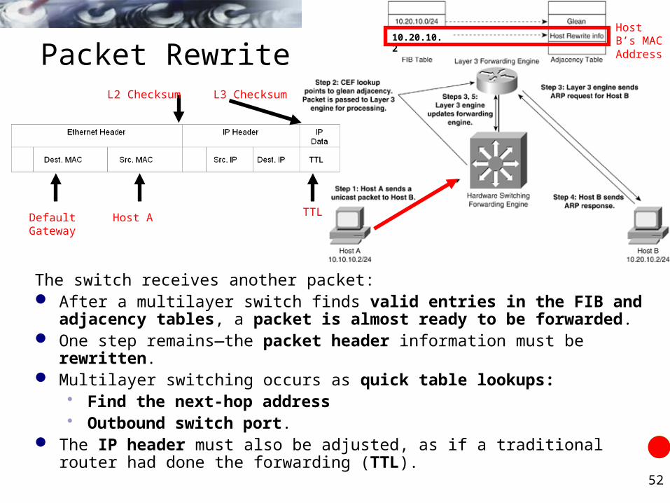
The switch receives another packet: After a multilayer switch finds valid entries in the FIB and adjacency tables,
a packet is almost ready to be forwarded. One step remains—the packet header information must be rewritten. Multilayer switching occurs as quick table lookups:
Find the next-hop address Outbound switch port.
The IP header must also be adjusted, as if a traditional router had done the forwarding (TTL).
Default Gateway
Host A TTL
L3 ChecksumL2 Checksum
10.20.10.2Host B’s MAC Address

53
Packet Rewrite
The packet rewrite engine makes the following changes to the packet just prior to forwarding:
Layer 2 destination address— Changed to the next-hop device's MAC address Layer 2 source address— Changed to the outbound Layer 3 switch interface's MAC
address Layer 3 IP Time To Live (TTL)— Decremented by one, as one router hop has just
occurred Layer 2 frame checksum— Recalculated to include changes to the Layer 2 and Layer 3
headers Layer 3 IP checksum— Recalculated to include changes to the IP header
Default Gateway
TTL
L3 ChecksumL2 Checksum
Host B MAC Add
TTL - 1
L2 Checksum L3 Checksum
Host AL3 switch outbound interface
10.20.10.2Host B’s MAC Address

54
Packet Rewrite
A traditional router would normally make the same changes to each packet. The multilayer switch must act as if a traditional router were being used,
making identical changes. The multilayer switch:
Can do this very efficiently with dedicated packet rewrite hardware and with address information obtained from table lookups.
Default Gateway
TTL
L3 ChecksumL2 Checksum
Host B MAC Add
TTL - 1
L2 Checksum L3 Checksum
Host AL3 switch outbound interface
10.20.10.2Host B’s MAC Address

55
Packet Rewrite
The switch performs a Layer 3 lookup and finds a CEF entry for Host B.
The switch rewrites packets per the adjacency information and forwards the packet to Host B on its VLAN.
Default Gateway
TTL
L3 ChecksumL2 Checksum
Host B MAC Add
TTL - 1
L2 Checksum L3 Checksum
Host AL3 switch outbound interface
10.20.10.2Host B’s MAC Address

56
CEF
Catalyst switches do not support routing of all types of frames in hardware. For example, the following list details common frame types that are not
supported by hardware switching and must punted (sent to the Layer 3 engine for processing): Packets with IP header options Packets sourced from or destined to tunnel interfaces Packets using Ethernet encapsulation types other than ARPA Packets that require fragmentation (exceed MTU of the interface)
Two types of CEF Central CEF or Accelerated CEF – Forwarding decisions done by
ASIC that is central to all interfaces. Distributed CEF (dCEF) – Forwarding decisions done on
independently on interfaces or line modules – line cards (faster).
57
Configuring a Routed Port
Switch(config)#ip routing
Step 1 : Configure IP routing.
Switch(config)#router ip_routing_protocol <options>
Step 4 : Configure the IP routing protocol if needed.
Switch(config-if)#no switchport
Step 2 : Create a routed port.
Switch(config-if)#ip address ip-address mask
Step 3 : Assign an IP address to the routed port.

58
Configuring Inter-VLAN Routing Through an SVI
Switch(config)#ip routing
Step 1 : Configure IP routing.
Switch(config)#router ip_routing_protocol <options>
Step 4 : Configure the IP routing protocol if needed.
Switch(config)#interface vlan vlan-id
Step 2 : Create an SVI interface.
Switch(config-if)#ip address ip-address mask
Step 3 : Assign an IP address to the SVI.

59
Enabling CEF
Switch(config-if)#ip cef
Switch(config-if)#ip route-cache cef
The commands required to enable CEF are platform dependent:
On the Cisco Catalyst 4000 switch
On the Cisco Catalyst 3550 switch

60
Verifying CEF
Switch#show ip cef [type mod/port | vlan_interface] [detail]
Switch# show ip cef vlan 11 detail
IP CEF with switching (Table Version 11), flags=0x0 10 routes, 0 reresolve, 0 unresolved (0 old, 0 new), peak 0 13 leaves, 12 nodes, 14248 bytes, 14 inserts, 1 invalidations 0 load sharing elements, 0 bytes, 0 references universal per-destination load sharing algorithm, id 4B936A24 2(0) CEF resets, 0 revisions of existing leaves Resolution Timer: Exponential (currently 1s, peak 1s) 0 in-place/0 aborted modifications refcounts: 1061 leaf, 1052 node
Table epoch: 0 (13 entries at this epoch)
172.16.11.0/24, version 6, epoch 0, attached, connected0 packets, 0 bytes via Vlan11, 0 dependencies valid glean adjacency

61
Verify Layer 3 Switching
Switch#show interface {{type mod/port} | {port-channel number}} | begin L3
Switch#show interface fastethernet 3/3 | begin L3 L3 in Switched: ucast: 0 pkt, 0 bytes - mcast: 12 pkt, 778 bytes mcast L3 out Switched: ucast: 0 pkt, 0 bytes - mcast: 0 pkt, 0 bytes 4046399 packets input, 349370039 bytes, 0 no buffer Received 3795255 broadcasts, 2 runts, 0 giants, 0 throttles .....Switch#

62
Displaying Hardware Layer 3 Switching Statistics
Switch#show interfaces {{type mod/port} | {port-channel number}} include switched
Switch#show interfaces gigabitethernet 9/5 | include switched L2 Switched: ucast: 8199 pkt, 1362060 bytes - mcast: 6980 pkt, 371952 bytesL3 in Switched: ucast: 3045 pkt, 742761 bytes - mcast: 0 pkt, 0 bytes mcastL3 out Switched: ucast: 2975 pkt, 693411 bytes - mcast: 0 pkt, 0 bytes

63
Adjacency Information
Switch#show adjacency [{{type mod/port} | {port-channel number}} | detail | internal | summary]
Switch#show adjacency gigabitethernet 9/5 detail Protocol Interface AddressIP GigabitEthernet9/5 172.20.53.206(11) 504 packets, 6110 bytes 00605C865B82 000164F83FA50800 ARP 03:49:31
64
Debugging CEF Operations
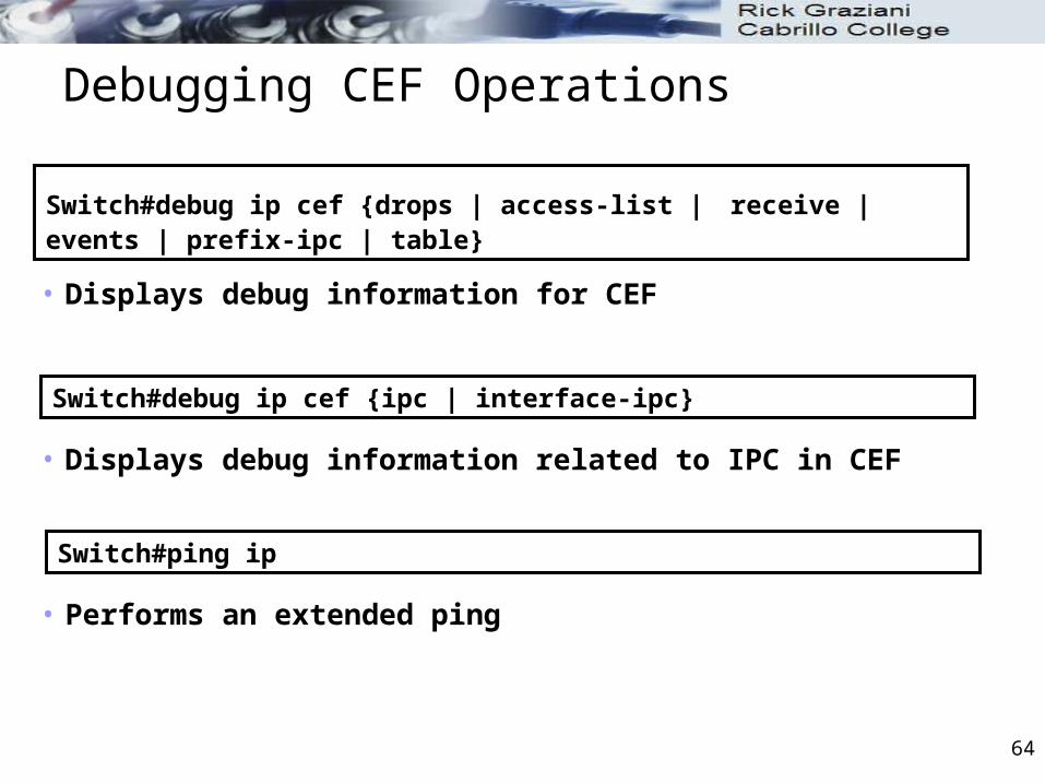
Switch#debug ip cef {drops | access-list | receive | events | prefix-ipc | table}
• Displays debug information for CEF
Switch#debug ip cef {ipc | interface-ipc}
• Displays debug information related to IPC in CEF
Switch#ping ip
• Performs an extended ping

65
CEF Summary
Layer 3 switching is high-performance packet switching in hardware.
MLS functionality can be implemented through CEF. CEF uses tables in hardware to forward packets. Specific commands are used to enable and verify
CEF operations. Commands to enable CEF are platform dependent. CEF problems can be matched to specific solutions. Specific commands are used to troubleshoot and solve CEF
problems. Ordered steps assist in troubleshooting CEF-based problems.

DHCP

67
IP Broadcast Forwarding
DHCP use IP subnet broadcasts to the 255.255.255.255 address. Routers do not route these packets by default. Routers and Layer 3 switches can be configured to forward these
DHCP and other UDP broadcast packets to a unicast address

68
DHCP Relay Agent
Layer 3 devices do not forward broadcasts. What issue does this cause for DHCP Servers?
Each subnet requires a DHCP server. To enable the DHCP relay agent feature, configure the ip helper-address command
with the DHCP server IP address(es) on the client VLAN interfaces.
MLS(config)#interface vlan 1MLS(configif)#description DHCP Server VLANMLS(config-if)#ip address 10.1.1.1 255.255.255.0MLS(config-if)#no ip directed-broadcast
MLS(config)#interface vlan 2MLS(config-ig)#description DHCP clientsMLS(config-if)#ip address 10.2.1.1 255.255.255.0MLS(config-if)#no shutdownMLS(config-if)#no ip directed-broadcastMLS(config-if)#ip helper-address 10.1.1.254

69
DHCP Relay Agent
The ip helper-address command not only forwards DHCP UDP packets but also forwards TFTP, DNS, Time, NetBIOS, name server, and BOOTP packets by default.
By default, the ip helper-address command forwards the eight UDPs services.

70
DHCP Relay Agent
ip helper-address - make sure the ip directed-broadcast is not configured on any outbound interfaces that the UDP broadcast packets need to traverse.
The no ip directed-broadcast command configures the router or switch to prevent the translation of a directed broadcast to a physical broadcast (MAC FF).
This is a default behavior since Cisco IOS Release 12.0, implemented as a security measure.
MLS(config)#interface vlan 1MLS(configif)#description DHCP Server VLANMLS(config-if)#ip address 10.1.1.1 255.255.255.0MLS(config-if)#no ip directed-broadcast
MLS(config)#interface vlan 2MLS(config-ig)#description DHCP clientsMLS(config-if)#ip address 10.1.2.1 255.255.255.0MLS(config-if)#no shutdownMLS(config-if)#no ip directed-broadcastMLS(config-if)#ip helper-address 10.1.1.254
See Improving Security on Routers: http://www.cisco.com/warp/public/707/21.html

71
UDP Broadcast Forwarding
To specify additional UDP broadcasts for forwarding by the router when configuring the ip helper-address interface command, use the following global command:
ip forward protocol udp udp_ports
Use the no option to remove default or configured applications.
Router(config)#interface vlan 1
Router(config-if)#ip address 10.100.1.1 255.255.255.0
Router(config-if)#ip helper-address 10.200.1.254
Router(config)#ip forward-protocol udp mobile-ip
Router(config)#no ip forward-protocol udp netbios-ns

Enterprise Network Design

73
Hierarchical approach
Hierarchical approach to network design enables the network to be: Efficient
Connect users with resources they need regardless of location Predictable behavior High availability
Intelligent Recover from failures and topology changes quickly in a predetermined
manner. Scalable
Supports future expansions and upgrades Easily Managed
Low maintenance

74
Layers
Access Layer Provides
End users connect to the network Layer 2 (VLAN) connectivity
Capabilities Low cost per switch port High port density Scalable uplinks to higher layers VLAN membership, QoS Resiliency through multiple links
Access Access
Distribution Distribution
Core

75
Layers
Distribution Layer Provides
Interconnection between access and core layers Sometimes called building distribution switches VLANs and broadcast domains converge (end) here Where switching (VLANs) meet routing
Capabilities Aggregation of multiple access-layer devices High Layer 3 throughput for packet handling (routing) Security and policy based connectivity functions through access lists or
packet filters QoS Scalable and resilient high-speed links to core and access layers
Access Access
Distribution Distribution
Core

76
Layers
Core Layer (“Backbone”) Provides
Connectivity of all distribution layer devices to the backbone Efficient packet switching
Capabilities High Layer 3 throughput No costly or unnecessary packet manipulations (ACLs) Redundancy and resiliency for high availability Advanced QoS
Access Access
Distribution Distribution
Core

77
Switch Block
Switch Block consists of: Two distribution switches that aggregate one or more access
layer switches. Each access layer switch has a pair of uplinks, one to each
distribution switch. Distribution switches may or may not have a link between them. Many different options!
Distribution Distribution
Access Access

78
Switch Block
Switch Block Contains switching devices from access and distribution layers. All switch blocks connect to the core block (campus backbone). Contains both Layer 2 and Layer 3 functionality Distribution Layer
Confines STP, VLAN Access Layer
Supports individual VLANs
Distribution Distribution
Access Access

79
Switch Block and Core Block
Switch Block Group of access layer switches connected to their distribution
switches. Core Block
Core switches that connect switch blocks. The campus network backbone.
Core
SwitchBlock
SwitchBlock
SwitchBlock

80
Typical Switch Block Design
Switch block becomes fully dependent upon STP convergence for paths and loop free connectivity. Should configure multiple Root bridges to take advantage of redundant
links Redundant links unused unless load balancing with PVST+ (RSTP)
Various adaptations of this.
Distribution Distribution
Access Access
Core
VLANs A,B VLANs A,B
L2 L2L2 L2
L3
L2
L3

81
Best Practice Switch Block Design: Option A
Layer 2 connectivity contained at the access layer Distribution Layer has only Layer 3 links. VLANs do not span across switches at all. Access Switches
VLANs contained within a single access layer switch, switch chassis or stacked switch
Layer 2 uplinks to distribution switch No dependence upon STP convergence Layer 3 link between distribution switches
Distribution Distribution
Access Access
Core
VLAN A VLAN B
L2
L3
L2L2 L2
L3
L3

82
Best Practice Switch Block Design: Option B
Limit layer 2 VLANs o the access layer switches. No dependence on STP convergence. Network convergence and stability is offered by the routing protocol.
Distribution
CoreL3 L3
Distribution L3
L3 L3
AccessAccess

83
Core Block
Connect two or more switch blocks in a campus network. Two basic core block designs:
Collapsed Core Dual Core

84
Collapsed Core
Collapsed Core: Hierarchy's core layer is collapsed into the distribution layer switches.
Both distribution and core layer functions provided within the same switch.
Found in smaller campus networks where the additional cost and performance of separate core switches is not warranted.
Layer 3 Links

85
Dual Core
Dual Core: Connects two or more switch blocks in a redundant fashion.
More scalable than collapsed cored.
Layer 3 Links

86
For more information
Enterprise Campus 3.0 Architecture: Overview and Framework http://www.cisco.com/en/US/docs/solutions/Enterprise/Campus/
campover.html

CIS 187 Multilayer Switched NetworksCCNP Switch
Inter-VLAN Routing, Multilayer Switching and CEF
Rick Graziani
Cabrillo College
Spring 2010