Circulating fault currents in two-winding and three ...
94
Two Winding Transformer Examples Setup 2W, 3LG Fault, Analysis @ 13.8kV side 2W, 3LG Fault, Analysis @ 115kV side 2W, 1LG Fault, Analysis @ 13.8kV side 2W, 1LG Fault, Analysis @ 115kV side 2W, LL Fault, Analysis @ 13.8kV side 2W, 2LG Fault, Analysis @ 13.8kV side Three Winding Transformer Example Setup 3W, 3LG Fault Analysis @ 13.8kV side 3W, 3LG Fault Analysis @ 115kV side 3W, 1LG Fault Analysis @ 13.8kV side 3W, 1LG Fault Analysis @ 115kV side 3W, LL Fault Analysis @ 13.8kV side 3W, LL Fault Analysis @ 115kV side 2W, 2LG Fault, Analysis @ 13.8kV side Symmetrical Fault Currents with Two-Winding and Three-Winding Transformers In this paper, we will setup a short circuit example for a 2W and 3W Transformer - hand calculate the short circuit phase and sequence qantities, and validate the quantities with a commercial short circuit software. By: Abdur Rehman PE Last Updated: Rev 1.1 – 2019-03-11
Transcript of Circulating fault currents in two-winding and three ...
Two Winding Transformer Examples Setup
2W, 3LG Fault, Analysis @ 13.8kV side
2W, 3LG Fault, Analysis @ 115kV side 2W, 1LG Fault, Analysis @ 13.8kV side
2W, 1LG Fault, Analysis @ 115kV side
2W, LL Fault, Analysis @ 13.8kV side
2W, 2LG Fault, Analysis @ 13.8kV side
Three Winding Transformer Example Setup 3W, 3LG Fault Analysis @ 13.8kV side
3W, 3LG Fault Analysis @ 115kV side 3W, 1LG Fault Analysis @ 13.8kV side
3W, 1LG Fault Analysis @ 115kV side
3W, LL Fault Analysis @ 13.8kV side
3W, LL Fault Analysis @ 115kV side
2W, 2LG Fault, Analysis @ 13.8kV side
Symmetrical Fault Currents with Two-Winding and Three-Winding Transformers
In this paper, we will setup a short circuit example for a 2W and 3W Transformer - hand calculate the short circuit phase and sequence qantities, and validate the quantities with a commercial
short circuit software.
By: Abdur Rehman PE
Last Updated: Rev 1.1 – 2019-03-11

Two Winding Transformer Examples Setup
2W, 3LG Fault, Analysis @ 13.8kV side
2W, 3LG Fault, Analysis @ 115kV side 2W, 1LG Fault, Analysis @ 13.8kV side
2W, 1LG Fault, Analysis @ 115kV side
2W, LL Fault, Analysis @ 13.8kV side
2W, 2LG Fault, Analysis @ 13.8kV side
Three Winding Transformer Example Setup 3W, 3LG Fault Analysis @ 13.8kV side
3W, 3LG Fault Analysis @ 115kV side 3W, 1LG Fault Analysis @ 13.8kV side
3W, 1LG Fault Analysis @ 115kV side
3W, LL Fault Analysis @ 13.8kV side
3W, LL Fault Analysis @ 115kV side
2W, 2LG Fault, Analysis @ 13.8kV side
Two Winding Transformer Example: DAB - Wye Connection Delta Wye Transformer connection is also explained in detail on our GeneralPAC YouTube channel. Please visit the link below: https://www.youtube.com/watch?v=j5tDh8QKftg&list=PLqJ0Y2s60r-5TG3jkbk9Er5OPI50i37kh
𝑍𝑍𝑠𝑠𝑠𝑠 =115𝑘𝑘𝑘𝑘2
600 𝑀𝑀𝑘𝑘𝑀𝑀= 22.04Ω
First, we’ll need to convert the MVA short-circuit of the generator to an impedance value. Since the generator is connected to the 115kV bus, we can use that as our voltage base to calculate the short circuit impedance.
𝑍𝑍𝑏𝑏𝑏𝑏𝑠𝑠𝑏𝑏 =𝐾𝐾𝑘𝑘𝑏𝑏𝑏𝑏𝑠𝑠𝑏𝑏𝑀𝑀𝑘𝑘𝑀𝑀𝑏𝑏𝑏𝑏𝑠𝑠𝑏𝑏
=(115𝑘𝑘𝑘𝑘)2
30 𝑀𝑀𝑘𝑘𝑀𝑀= 440.83Ω
We need to decide an impedance base for our system. Since the 2-winding transformer is given in a 30MVA base, it’s worthwhile to select 30MVA as our impedance base.
𝑍𝑍𝑠𝑠𝑠𝑠@30𝑀𝑀𝑀𝑀𝑀𝑀 =𝑍𝑍𝑠𝑠𝑠𝑠𝑍𝑍𝑏𝑏𝑏𝑏𝑠𝑠𝑏𝑏
=22.04 Ω
440.83 Ω= 0.05 𝑝𝑝𝑝𝑝
Lastly, we must convert the short-circuit impedance of the generator to a 30 MVA base. Hand calculating short circuit current is much easier in a per unit system. So that’s why we’re interested in the per unit value.
𝑍𝑍𝑠𝑠𝑠𝑠@30𝑀𝑀𝑀𝑀𝑀𝑀 = 0 + 𝑗𝑗 ∗ 0.05 𝑝𝑝𝑝𝑝 The resistive component will be ignored. So we will assume the 0.05 pu impedance is fully reactive.
𝑆𝑆𝑆𝑆𝑆𝑆𝑆𝑆ℎ𝑟𝑟𝑟𝑟𝑆𝑆𝑟𝑟𝑝𝑝𝑟𝑟 𝑅𝑅𝑅𝑅𝑅𝑅𝑆𝑆𝑅𝑅𝑅𝑅𝑆𝑆𝑆𝑆𝑅𝑅 = 𝑇𝑇𝑟𝑟𝑅𝑅𝑆𝑆𝑟𝑟𝑇𝑇𝑅𝑅𝑆𝑆𝑅𝑅 𝑅𝑅𝑅𝑅𝑅𝑅𝑆𝑆𝑅𝑅𝑅𝑅𝑆𝑆𝑆𝑆𝑅𝑅 = 𝑆𝑆𝑝𝑝𝑆𝑆 𝑇𝑇𝑟𝑟𝑅𝑅𝑆𝑆𝑟𝑟𝑇𝑇𝑅𝑅𝑆𝑆𝑅𝑅 𝑅𝑅𝑅𝑅𝑅𝑅𝑆𝑆𝑅𝑅𝑅𝑅𝑆𝑆𝑆𝑆𝑅𝑅
= 0.05 𝑝𝑝𝑝𝑝
We are also going to assume that the synchronous reactance of the generator is equal to the transient reactive which is equal to the sub transient reactance. Typically, these values are different, however, for simplification purposes, we’ll consider them all equal.
𝑍𝑍𝑇𝑇
(1) = 𝑍𝑍𝑇𝑇(2) = 0 + 𝑗𝑗0.10 𝑝𝑝𝑝𝑝
𝑍𝑍𝑇𝑇
(0) = 0 + 𝑗𝑗0.10 𝑝𝑝𝑝𝑝
Since the transformer impedance is given as 10% at 30 MVA (positive and zero sequence), and we selected 30 MVA for the generator base, the per unit value is simply 0.10.
Two Winding Transformer Examples Setup
2W, 3LG Fault, Analysis @ 13.8kV side
2W, 3LG Fault, Analysis @ 115kV side 2W, 1LG Fault, Analysis @ 13.8kV side
2W, 1LG Fault, Analysis @ 115kV side
2W, LL Fault, Analysis @ 13.8kV side
2W, 2LG Fault, Analysis @ 13.8kV side
Three Winding Transformer Example Setup 3W, 3LG Fault Analysis @ 13.8kV side
3W, 3LG Fault Analysis @ 115kV side 3W, 1LG Fault Analysis @ 13.8kV side
3W, 1LG Fault Analysis @ 115kV side
3W, LL Fault Analysis @ 13.8kV side
3W, LL Fault Analysis @ 115kV side
2W, 2LG Fault, Analysis @ 13.8kV side
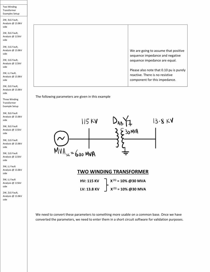
The following parameters are given in this example
We need to convert these parameters to something more usable on a common base. Once we have converted the parameters, we need to enter them in a short circuit software for validation purposes.
We are going to assume that positive sequence impedance and negative sequence impedance are equal. Please also note that 0.10 pu is purely reactive. There is no resistive component for this impedance.
TWO WINDING TRANSFORMER
HV: 115 KV X (1) = 10% @30 MVA
LV: 13.8 KV X (1) = 10% @30 MVA

Two Winding Transformer Examples Setup
2W, 3LG Fault, Analysis @ 13.8kV side
2W, 3LG Fault, Analysis @ 115kV side 2W, 1LG Fault, Analysis @ 13.8kV side
2W, 1LG Fault, Analysis @ 115kV side
2W, LL Fault, Analysis @ 13.8kV side
2W, 2LG Fault, Analysis @ 13.8kV side
Three Winding Transformer Example Setup 3W, 3LG Fault Analysis @ 13.8kV side
3W, 3LG Fault Analysis @ 115kV side 3W, 1LG Fault Analysis @ 13.8kV side
3W, 1LG Fault Analysis @ 115kV side
3W, LL Fault Analysis @ 13.8kV side
3W, LL Fault Analysis @ 115kV side
2W, 2LG Fault, Analysis @ 13.8kV side
Building the Short-circuit Model for 2W, DAB-Wye XFMR Now that we have calculated all the impedances to a common 30 MVA base, let’s model the system in ASPEN OneLiner short-circuit tool, so we can validate our hand calculations later.
The generator information was modeled using the information to the left. As shown, the pre-fault per unit voltage is selected as 1 pu and angle is at 0 degrees.
Two Winding Transformer Examples Setup
2W, 3LG Fault, Analysis @ 13.8kV side
2W, 3LG Fault, Analysis @ 115kV side 2W, 1LG Fault, Analysis @ 13.8kV side
2W, 1LG Fault, Analysis @ 115kV side
2W, LL Fault, Analysis @ 13.8kV side
2W, 2LG Fault, Analysis @ 13.8kV side
Three Winding Transformer Example Setup 3W, 3LG Fault Analysis @ 13.8kV side
3W, 3LG Fault Analysis @ 115kV side 3W, 1LG Fault Analysis @ 13.8kV side
3W, 1LG Fault Analysis @ 115kV side
3W, LL Fault Analysis @ 13.8kV side
3W, LL Fault Analysis @ 115kV side
2W, 2LG Fault, Analysis @ 13.8kV side
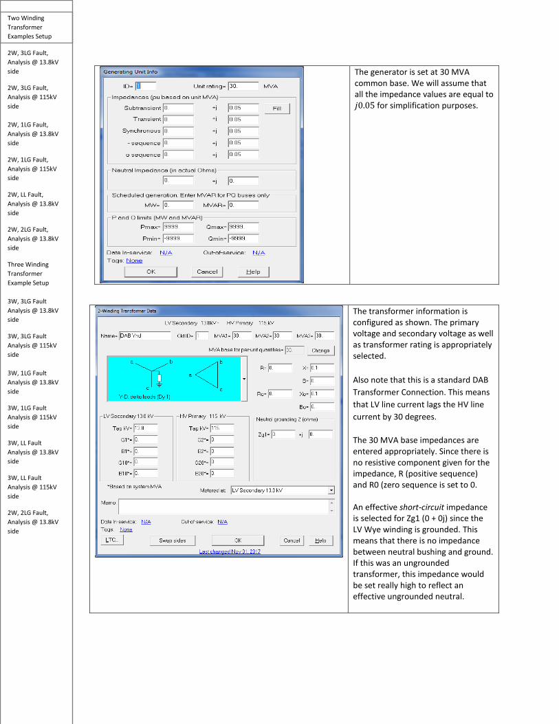
The generator is set at 30 MVA common base. We will assume that all the impedance values are equal to 𝑗𝑗0.05 for simplification purposes.
The transformer information is configured as shown. The primary voltage and secondary voltage as well as transformer rating is appropriately selected. Also note that this is a standard DAB Transformer Connection. This means that LV line current lags the HV line current by 30 degrees. The 30 MVA base impedances are entered appropriately. Since there is no resistive component given for the impedance, R (positive sequence) and R0 (zero sequence is set to 0. An effective short-circuit impedance is selected for Zg1 (0 + 0j) since the LV Wye winding is grounded. This means that there is no impedance between neutral bushing and ground. If this was an ungrounded transformer, this impedance would be set really high to reflect an effective ungrounded neutral.

Two Winding Transformer Examples Setup
2W, 3LG Fault, Analysis @ 13.8kV side
2W, 3LG Fault, Analysis @ 115kV side 2W, 1LG Fault, Analysis @ 13.8kV side
2W, 1LG Fault, Analysis @ 115kV side
2W, LL Fault, Analysis @ 13.8kV side
2W, 2LG Fault, Analysis @ 13.8kV side
Three Winding Transformer Example Setup 3W, 3LG Fault Analysis @ 13.8kV side
3W, 3LG Fault Analysis @ 115kV side 3W, 1LG Fault Analysis @ 13.8kV side
3W, 1LG Fault Analysis @ 115kV side
3W, LL Fault Analysis @ 13.8kV side
3W, LL Fault Analysis @ 115kV side
2W, 2LG Fault, Analysis @ 13.8kV side
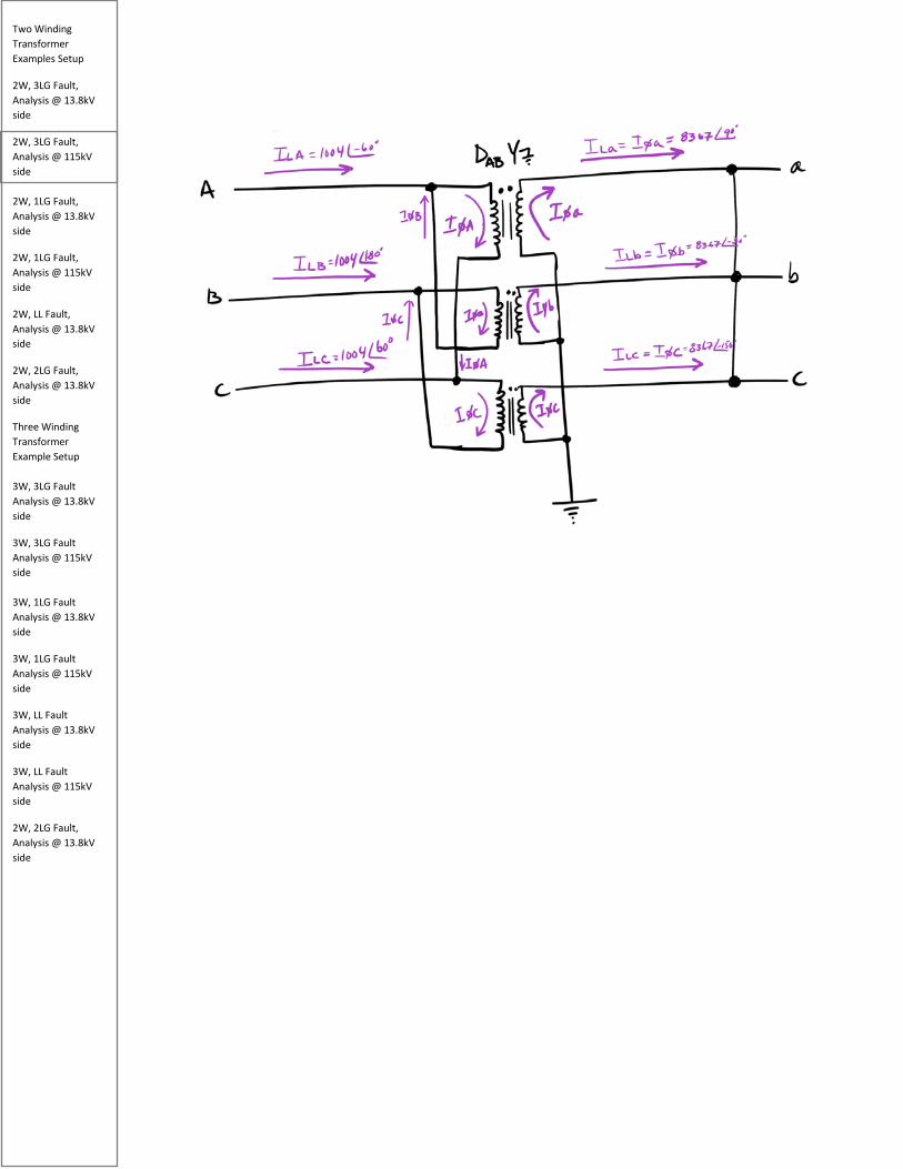
2W DAB-Wye XFMR Current and Voltage Transformation The following section is a brief discussion on current and voltage transformation for a DAB Wye-grounded transformer.
When we compare the HV to LV line current/voltage for the DAB-Wye grounded transformer, we should expect a difference in both magnitude and phase. For example, if we compare 𝐼𝐼𝐿𝐿𝑀𝑀 with 𝐼𝐼∅𝑀𝑀 both on the HV side, we should expect a 1.73 difference in the magnitude and 30 degrees phase shift in the angle.
Therefore, if we compare the LV line current quantity (𝐼𝐼𝐿𝐿𝑏𝑏) with the HV line current quantity (𝐼𝐼𝐿𝐿𝑀𝑀), in addition to the magnitude difference which is driven by the transformer ratio, we should expect LV
Two Winding Transformer Examples Setup
2W, 3LG Fault, Analysis @ 13.8kV side
2W, 3LG Fault, Analysis @ 115kV side 2W, 1LG Fault, Analysis @ 13.8kV side
2W, 1LG Fault, Analysis @ 115kV side
2W, LL Fault, Analysis @ 13.8kV side
2W, 2LG Fault, Analysis @ 13.8kV side
Three Winding Transformer Example Setup 3W, 3LG Fault Analysis @ 13.8kV side
3W, 3LG Fault Analysis @ 115kV side 3W, 1LG Fault Analysis @ 13.8kV side
3W, 1LG Fault Analysis @ 115kV side
3W, LL Fault Analysis @ 13.8kV side
3W, LL Fault Analysis @ 115kV side
2W, 2LG Fault, Analysis @ 13.8kV side
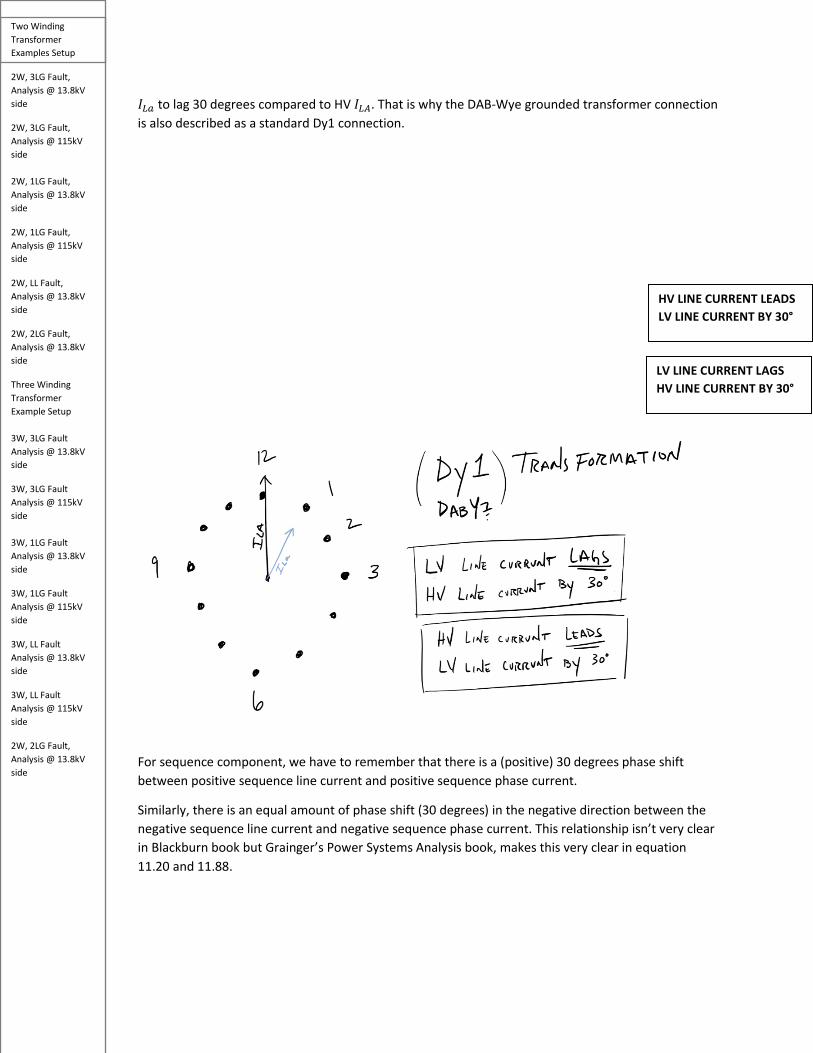
𝐼𝐼𝐿𝐿𝑏𝑏 to lag 30 degrees compared to HV 𝐼𝐼𝐿𝐿𝑀𝑀. That is why the DAB-Wye grounded transformer connection is also described as a standard Dy1 connection.
For sequence component, we have to remember that there is a (positive) 30 degrees phase shift between positive sequence line current and positive sequence phase current.
Similarly, there is an equal amount of phase shift (30 degrees) in the negative direction between the negative sequence line current and negative sequence phase current. This relationship isn’t very clear in Blackburn book but Grainger’s Power Systems Analysis book, makes this very clear in equation 11.20 and 11.88.
LV LINE CURRENT LAGS HV LINE CURRENT BY 30°
HV LINE CURRENT LEADS LV LINE CURRENT BY 30°

Two Winding Transformer Examples Setup
2W, 3LG Fault, Analysis @ 13.8kV side
2W, 3LG Fault, Analysis @ 115kV side 2W, 1LG Fault, Analysis @ 13.8kV side
2W, 1LG Fault, Analysis @ 115kV side
2W, LL Fault, Analysis @ 13.8kV side
2W, 2LG Fault, Analysis @ 13.8kV side
Three Winding Transformer Example Setup 3W, 3LG Fault Analysis @ 13.8kV side
3W, 3LG Fault Analysis @ 115kV side 3W, 1LG Fault Analysis @ 13.8kV side
3W, 1LG Fault Analysis @ 115kV side
3W, LL Fault Analysis @ 13.8kV side
3W, LL Fault Analysis @ 115kV side
2W, 2LG Fault, Analysis @ 13.8kV side
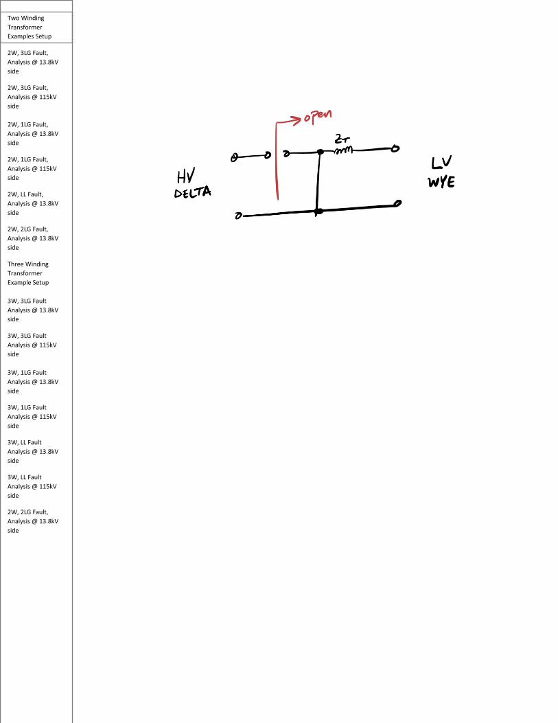
2W Delta-Wye XFMR Zero Sequence Connection According to Blackburn Figure A4.2-1, the zero sequence impedance seen from the HV, Delta side will effectively be open while the Wye-grounded side is seen as a short with the transformer impedance. This is due to the zero sequence current trap on the Delta side (it does not cause the zero sequence current to flow on the Wye winding), while the grounded-wye causes the short to ground.
Two Winding Transformer Examples Setup
2W, 3LG Fault, Analysis @ 13.8kV side
2W, 3LG Fault, Analysis @ 115kV side 2W, 1LG Fault, Analysis @ 13.8kV side
2W, 1LG Fault, Analysis @ 115kV side
2W, LL Fault, Analysis @ 13.8kV side
2W, 2LG Fault, Analysis @ 13.8kV side
Three Winding Transformer Example Setup 3W, 3LG Fault Analysis @ 13.8kV side
3W, 3LG Fault Analysis @ 115kV side 3W, 1LG Fault Analysis @ 13.8kV side
3W, 1LG Fault Analysis @ 115kV side
3W, LL Fault Analysis @ 13.8kV side
3W, LL Fault Analysis @ 115kV side
2W, 2LG Fault, Analysis @ 13.8kV side
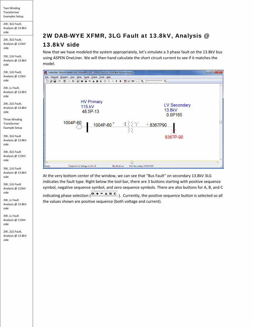
2W DAB-WYE XFMR, 3LG Fault at 13.8kV, Analysis @ 13.8kV side Now that we have modeled the system appropriately, let’s simulate a 3 phase fault on the 13.8kV bus using ASPEN OneLiner. We will then hand calculate the short circuit current to see if it matches the model.
At the very bottom center of the window, we can see that “Bus Fault” on secondary 13.8kV 3LG indicates the fault type. Right below the tool bar, there are 3 buttons starting with positive sequence symbol, negative sequence symbol, and zero sequence symbols. There are also buttons for A, B, and C
indicating phase selection ( ). Currently, the positive sequence button is selected so all the values shown are positive sequence (both voltage and current).

Two Winding Transformer Examples Setup
2W, 3LG Fault, Analysis @ 13.8kV side
2W, 3LG Fault, Analysis @ 115kV side 2W, 1LG Fault, Analysis @ 13.8kV side
2W, 1LG Fault, Analysis @ 115kV side
2W, LL Fault, Analysis @ 13.8kV side
2W, 2LG Fault, Analysis @ 13.8kV side
Three Winding Transformer Example Setup 3W, 3LG Fault Analysis @ 13.8kV side
3W, 3LG Fault Analysis @ 115kV side 3W, 1LG Fault Analysis @ 13.8kV side
3W, 1LG Fault Analysis @ 115kV side
3W, LL Fault Analysis @ 13.8kV side
3W, LL Fault Analysis @ 115kV side
2W, 2LG Fault, Analysis @ 13.8kV side
The 3 phase fault on the 13.8kV side produces the following sequence and phase currents.
𝐼𝐼𝑀𝑀(1) = 8367∠90° 𝐼𝐼𝑀𝑀 = 8367∠90°
𝐼𝐼𝑀𝑀(2) = 0 𝐼𝐼𝐵𝐵 = 8367∠-30°
𝐼𝐼𝑀𝑀(0) = 0 𝐼𝐼𝐶𝐶 = 8367∠-150°
Now that we have reference values, let’s try to hand calculating a 3 phase fault and comparing the hand calculations with the simulation software. We will draw the positive, negative, and zero sequence networks as shown below.
For the positive sequence network, 𝑗𝑗0.05 is clearly the generator impedance while the transformer impedance is clearly 𝑗𝑗0.10. Additionally, we will define our pre-fault voltage as 1pu at 0 degrees. It’s

Two Winding Transformer Examples Setup
2W, 3LG Fault, Analysis @ 13.8kV side
2W, 3LG Fault, Analysis @ 115kV side 2W, 1LG Fault, Analysis @ 13.8kV side
2W, 1LG Fault, Analysis @ 115kV side
2W, LL Fault, Analysis @ 13.8kV side
2W, 2LG Fault, Analysis @ 13.8kV side
Three Winding Transformer Example Setup 3W, 3LG Fault Analysis @ 13.8kV side
3W, 3LG Fault Analysis @ 115kV side 3W, 1LG Fault Analysis @ 13.8kV side
3W, 1LG Fault Analysis @ 115kV side
3W, LL Fault Analysis @ 13.8kV side
3W, LL Fault Analysis @ 115kV side
2W, 2LG Fault, Analysis @ 13.8kV side
interesting to note that some books use 𝑗𝑗1.0 𝑟𝑟𝑟𝑟 1∠90° for a pre-fault voltage instead of 1∠0°. This will result in the same fault magnitudes, however, there will be a difference in the fault angle. For the purpose of this example, we will use a pre-fault voltage of 1∠0°.
The negative sequence network is like the positive sequence except it does not have a voltage source. Generators do not generate negative sequence, but negative sequence current flows through their windings, which is why we have the generator impedance 𝑗𝑗0.05 included in the sequence network. It is very common to see similar values for positive and negative sequence networks in the industry as well.
The zero sequence network is very different from the other sequence networks. According to Blackburn, it must satisfy the flow of equal and in-phase current in the three phases. Furthermore, transformer and line zero sequence currents are very different than positive and negative sequence currents.
Depending on the construction of the transformer, the zero sequence impedance could be 85-90% of the positive sequence impedance – in our model however, we were asked to enter the zero sequence impedance values for the transformer and we entered the same values as the positive sequence impedance.
Two Winding Transformer Examples Setup
2W, 3LG Fault, Analysis @ 13.8kV side
2W, 3LG Fault, Analysis @ 115kV side 2W, 1LG Fault, Analysis @ 13.8kV side
2W, 1LG Fault, Analysis @ 115kV side
2W, LL Fault, Analysis @ 13.8kV side
2W, 2LG Fault, Analysis @ 13.8kV side
Three Winding Transformer Example Setup 3W, 3LG Fault Analysis @ 13.8kV side
3W, 3LG Fault Analysis @ 115kV side 3W, 1LG Fault Analysis @ 13.8kV side
3W, 1LG Fault Analysis @ 115kV side
3W, LL Fault Analysis @ 13.8kV side
3W, LL Fault Analysis @ 115kV side
2W, 2LG Fault, Analysis @ 13.8kV side
The effective transmission line impedance is also different. When a 1LG fault occurs, the return path of the fault involves ground wires, the earth, effects of the cable sheath, etc.
For positive and negative sequence networks, it’s a one-way impedance from one end to another. For this reason, the zero sequence impedance is typically 200-600% of the positive impedance. Please note that we don’t have any transmission lines in our example.
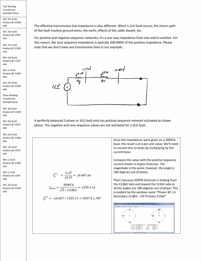
A perfectly balanced 3 phase or 3LG fault only has positive sequence network activated as shown above. The negative and zero sequence values are not activated for a 3LG fault.
𝐼𝐼𝑀𝑀(1) =
1∠0°𝑗𝑗0.15
= -𝑗𝑗6.667 𝑝𝑝𝑝𝑝
𝐼𝐼𝐵𝐵𝑏𝑏𝑠𝑠𝑏𝑏 =30𝑀𝑀𝑘𝑘𝑀𝑀
√3 ∗ 13.8𝑘𝑘𝑘𝑘= 1255.11𝑀𝑀
𝐼𝐼𝑀𝑀
(1) = −𝑗𝑗6.667 ∗ 1255.11 = 8367𝑀𝑀 ∠-90°
Since the impedances were given on a 30MVA base, the result is at a per unit value. We’ll need to convert this to amps by multiplying by the current base. Compare this value with the positive sequence current shown in Aspen OneLiner. The magnitude is the same, however, the angle is 180 degrees out of phase. That’s because ASPEN OneLiner is looking from the 13.8kV side and toward the 115kV side so all the angles are 180 degrees out of phase. This is evident by the window name “Phasor #2: LV Secondary 13.8kV – HV Primary 115kV”
Two Winding Transformer Examples Setup
2W, 3LG Fault, Analysis @ 13.8kV side
2W, 3LG Fault, Analysis @ 115kV side 2W, 1LG Fault, Analysis @ 13.8kV side
2W, 1LG Fault, Analysis @ 115kV side
2W, LL Fault, Analysis @ 13.8kV side
2W, 2LG Fault, Analysis @ 13.8kV side
Three Winding Transformer Example Setup 3W, 3LG Fault Analysis @ 13.8kV side
3W, 3LG Fault Analysis @ 115kV side 3W, 1LG Fault Analysis @ 13.8kV side
3W, 1LG Fault Analysis @ 115kV side
3W, LL Fault Analysis @ 13.8kV side
3W, LL Fault Analysis @ 115kV side
2W, 2LG Fault, Analysis @ 13.8kV side
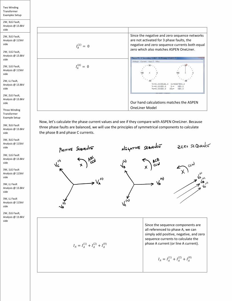
𝐼𝐼𝑀𝑀
(2) = 0
Since the negative and zero sequence networks are not activated for 3 phase faults, the negative and zero sequence currents both equal zero which also matches ASPEN OneLiner.
Our hand calculations matches the ASPEN OneLiner Model
𝐼𝐼𝑀𝑀
(0) = 0
Now, let’s calculate the phase current values and see if they compare with ASPEN OneLiner. Because three phase faults are balanced, we will use the principles of symmetrical components to calculate the phase B and phase C currents.
𝐼𝐼𝑀𝑀 = 𝐼𝐼𝑀𝑀
(1) + 𝐼𝐼𝑀𝑀(2) + 𝐼𝐼𝑀𝑀
(0)
Since the sequence components are all referenced to phase A, we can simply add positive, negative, and zero sequence currents to calculate the phase A current (or line A current).
𝐼𝐼𝑀𝑀 = 𝐼𝐼𝑀𝑀(1) + 𝐼𝐼𝑀𝑀
(2) + 𝐼𝐼𝑀𝑀(0)
Two Winding Transformer Examples Setup
2W, 3LG Fault, Analysis @ 13.8kV side
2W, 3LG Fault, Analysis @ 115kV side 2W, 1LG Fault, Analysis @ 13.8kV side
2W, 1LG Fault, Analysis @ 115kV side
2W, LL Fault, Analysis @ 13.8kV side
2W, 2LG Fault, Analysis @ 13.8kV side
Three Winding Transformer Example Setup 3W, 3LG Fault Analysis @ 13.8kV side
3W, 3LG Fault Analysis @ 115kV side 3W, 1LG Fault Analysis @ 13.8kV side
3W, 1LG Fault Analysis @ 115kV side
3W, LL Fault Analysis @ 13.8kV side
3W, LL Fault Analysis @ 115kV side
2W, 2LG Fault, Analysis @ 13.8kV side
𝐼𝐼𝐵𝐵 = 𝑅𝑅2 ∙ 𝐼𝐼𝑀𝑀
(1) + 𝑅𝑅 ∙ 𝐼𝐼𝑀𝑀(2) + 𝐼𝐼𝑀𝑀
(0)
𝑅𝑅 = 1∠120° 𝑅𝑅2 = 1∠240°
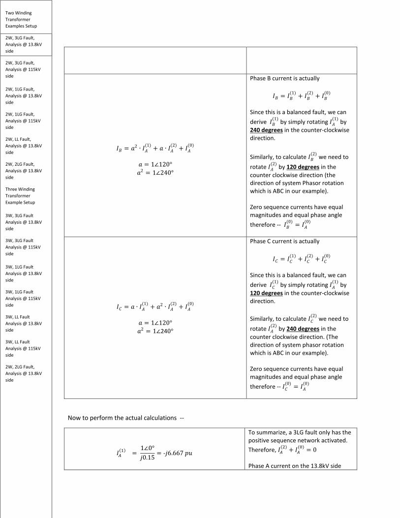
Phase B current is actually
𝐼𝐼𝐵𝐵 = 𝐼𝐼𝐵𝐵(1) + 𝐼𝐼𝐵𝐵
(2) + 𝐼𝐼𝐵𝐵(0)
Since this is a balanced fault, we can derive 𝐼𝐼𝐵𝐵
(1) by simply rotating 𝐼𝐼𝑀𝑀(1) by
240 degrees in the counter-clockwise direction. Similarly, to calculate 𝐼𝐼𝐵𝐵
(2) we need to rotate 𝐼𝐼𝑀𝑀
(2) by 120 degrees in the counter clockwise direction (the direction of system Phasor rotation which is ABC in our example). Zero sequence currents have equal magnitudes and equal phase angle therefore -- 𝐼𝐼𝐵𝐵
(0) = 𝐼𝐼𝑀𝑀(0)
𝐼𝐼𝐶𝐶 = 𝑅𝑅 ∙ 𝐼𝐼𝑀𝑀(1) + 𝑅𝑅2 ∙ 𝐼𝐼𝑀𝑀
(2) + 𝐼𝐼𝑀𝑀(0)
𝑅𝑅 = 1∠120° 𝑅𝑅2 = 1∠240°
Phase C current is actually
𝐼𝐼𝐶𝐶 = 𝐼𝐼𝐶𝐶(1) + 𝐼𝐼𝐶𝐶
(2) + 𝐼𝐼𝐶𝐶(0)
Since this is a balanced fault, we can derive 𝐼𝐼𝐶𝐶
(1) by simply rotating 𝐼𝐼𝑀𝑀(1) by
120 degrees in the counter-clockwise direction. Similarly, to calculate 𝐼𝐼𝐶𝐶
(2) we need to rotate 𝐼𝐼𝑀𝑀
(2) by 240 degrees in the counter clockwise direction. (The direction of system phasor rotation which is ABC in our example). Zero sequence currents have equal magnitudes and equal phase angle therefore -- 𝐼𝐼𝐶𝐶
(0) = 𝐼𝐼𝑀𝑀(0)
Now to perform the actual calculations --
𝐼𝐼𝑀𝑀(1) =
1∠0°𝑗𝑗0.15
= -𝑗𝑗6.667 𝑝𝑝𝑝𝑝
To summarize, a 3LG fault only has the positive sequence network activated. Therefore, 𝐼𝐼𝑀𝑀
(2) + 𝐼𝐼𝑀𝑀(0) = 0
Phase A current on the 13.8kV side

Two Winding Transformer Examples Setup
2W, 3LG Fault, Analysis @ 13.8kV side
2W, 3LG Fault, Analysis @ 115kV side 2W, 1LG Fault, Analysis @ 13.8kV side
2W, 1LG Fault, Analysis @ 115kV side
2W, LL Fault, Analysis @ 13.8kV side
2W, 2LG Fault, Analysis @ 13.8kV side
Three Winding Transformer Example Setup 3W, 3LG Fault Analysis @ 13.8kV side
3W, 3LG Fault Analysis @ 115kV side 3W, 1LG Fault Analysis @ 13.8kV side
3W, 1LG Fault Analysis @ 115kV side
3W, LL Fault Analysis @ 13.8kV side
3W, LL Fault Analysis @ 115kV side
2W, 2LG Fault, Analysis @ 13.8kV side
𝐼𝐼𝐵𝐵𝑏𝑏𝑠𝑠𝑏𝑏 =30𝑀𝑀𝑘𝑘𝑀𝑀
√3 ∗ 13.08𝑘𝑘𝑘𝑘= 1324.20𝑀𝑀
𝐼𝐼𝑀𝑀
(1) = −𝑗𝑗6.667 ∗ 1324.20 = 8367𝑀𝑀 ∠-90°
𝐼𝐼𝑀𝑀 = 𝐼𝐼𝑀𝑀(1) + 𝐼𝐼𝑀𝑀
(2) + 𝐼𝐼𝑀𝑀(0) = 𝐼𝐼𝑀𝑀
(1) = 8367𝑀𝑀 ∠-90°
equals 8367𝑀𝑀 ∠-90° This matches the ASPEN OneLiner result. However, the tool is showing the angle at +90 degrees.
The reason why is because the tool is looking at the phasors from the 13.8 kV side and toward the source (115 kV side).
𝐼𝐼𝐵𝐵 = 𝑅𝑅2 ∙ 𝐼𝐼𝑀𝑀
(1) + 𝑅𝑅 ∙ 𝐼𝐼𝑀𝑀(2) + 𝐼𝐼𝑀𝑀
(0) 𝐼𝐼𝐵𝐵 = 𝑅𝑅2 ∙ 𝐼𝐼𝑀𝑀
(1) = (1∠240°) ∗ (8367𝑀𝑀 ∠-90°) = 8367𝑀𝑀 ∠150°
Since 𝐼𝐼𝑀𝑀
(2)𝑅𝑅𝑆𝑆𝑎𝑎 𝐼𝐼𝑀𝑀(0)are both 0 for a 3
phase fault, the equation simplifies to 𝐼𝐼𝐵𝐵 = 𝑅𝑅2 ∙ 𝐼𝐼𝑀𝑀
(1) This matches the ASPEN OneLiner result but with a 180 degrees phase shift.
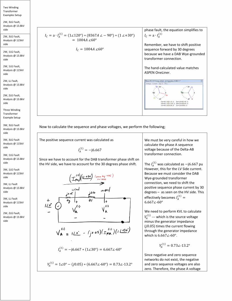
𝐼𝐼𝐶𝐶 = a ∙ 𝐼𝐼𝑀𝑀
(1) + 𝑅𝑅2 ∙ 𝐼𝐼𝑀𝑀(2) + 𝐼𝐼𝑀𝑀
(0) 𝐼𝐼𝐶𝐶 = a ∙ 𝐼𝐼𝑀𝑀
(1) = (1∠120°) ∗ (8367𝑀𝑀 ∠ − 90°) = 8367𝑀𝑀 ∠30°
Since 𝐼𝐼𝑀𝑀
(2)𝑅𝑅𝑆𝑆𝑎𝑎 𝐼𝐼𝑀𝑀(0)are both 0 for a 3
phase fault, the equation simplifies to 𝐼𝐼𝐶𝐶 = a ∙ 𝐼𝐼𝑀𝑀
(1) This matches the ASPEN OneLiner result but with a 180 degrees phase shift for the reasons explained above.
Now to calculate the sequence and phase voltages, we perform the following
Here, we see that positive sequence phase A voltage equal 0 kV which is, what we should expect because the

Two Winding Transformer Examples Setup
2W, 3LG Fault, Analysis @ 13.8kV side
2W, 3LG Fault, Analysis @ 115kV side 2W, 1LG Fault, Analysis @ 13.8kV side
2W, 1LG Fault, Analysis @ 115kV side
2W, LL Fault, Analysis @ 13.8kV side
2W, 2LG Fault, Analysis @ 13.8kV side
Three Winding Transformer Example Setup 3W, 3LG Fault Analysis @ 13.8kV side
3W, 3LG Fault Analysis @ 115kV side 3W, 1LG Fault Analysis @ 13.8kV side
3W, 1LG Fault Analysis @ 115kV side
3W, LL Fault Analysis @ 13.8kV side
3W, LL Fault Analysis @ 115kV side
2W, 2LG Fault, Analysis @ 13.8kV side
𝑘𝑘𝑀𝑀(1) = 1∠0° − (j0.15) ∗ (−j6.667) = 0pu
𝑘𝑘𝑀𝑀(1) = 0kV∠0°
𝑘𝑘𝑀𝑀 = 𝑘𝑘𝑀𝑀(1) + 𝑘𝑘𝑀𝑀
(2) + 𝑘𝑘𝑀𝑀(0) = 0 kV∠0°
short-circuit should drive the voltage to zero. This agrees with the Aspen model.
𝑘𝑘𝐵𝐵 = 𝑅𝑅2 ∙ 𝑘𝑘𝑀𝑀(1) = (1∠240°) ∗ (0V∠0°) = 0kV
As discussed earlier, since this is a balanced three phase fault, all the phase currents will have equal magnitude and displaced by 120 degrees. And since negative and zero sequence does not exists for three phase faults, we rotate the positive sequence voltage by 240 degrees in the CCW direction to get phase B voltage. However, since the positive sequence voltage is zero, the phase B voltage is also zero. The hand-calculated value matches ASPEN OneLiner.
𝑘𝑘𝐶𝐶 = a ∙ 𝑘𝑘𝑀𝑀(1) = (1∠120°) ∗ (0 kV∠0°) = 0kV
We rotate positive sequence A by 120 degrees in the CCW direction to get phase C voltage. But since positive sequence voltage is zero, phase C voltage is also zero. The hand-calculated value matches ASPEN OneLiner.

Two Winding Transformer Examples Setup
2W, 3LG Fault, Analysis @ 13.8kV side
2W, 3LG Fault, Analysis @ 115kV side 2W, 1LG Fault, Analysis @ 13.8kV side
2W, 1LG Fault, Analysis @ 115kV side
2W, LL Fault, Analysis @ 13.8kV side
2W, 2LG Fault, Analysis @ 13.8kV side
Three Winding Transformer Example Setup 3W, 3LG Fault Analysis @ 13.8kV side
3W, 3LG Fault Analysis @ 115kV side 3W, 1LG Fault Analysis @ 13.8kV side
3W, 1LG Fault Analysis @ 115kV side
3W, LL Fault Analysis @ 13.8kV side
3W, LL Fault Analysis @ 115kV side
2W, 2LG Fault, Analysis @ 13.8kV side
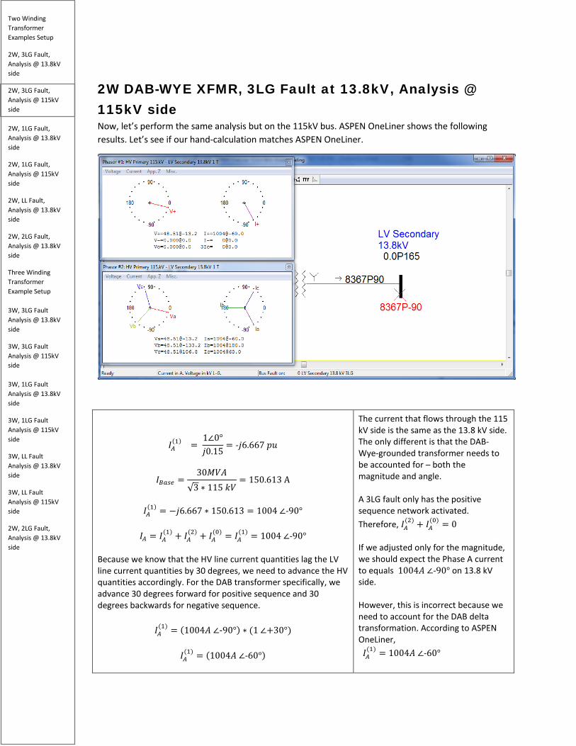
2W DAB-WYE XFMR, 3LG Fault at 13.8kV, Analysis @ 115kV side Now, let’s perform the same analysis but on the 115kV bus. ASPEN OneLiner shows the following results. Let’s see if our hand-calculation matches ASPEN OneLiner.
𝐼𝐼𝑀𝑀(1) =
1∠0°𝑗𝑗0.15
= -𝑗𝑗6.667 𝑝𝑝𝑝𝑝
𝐼𝐼𝐵𝐵𝑏𝑏𝑠𝑠𝑏𝑏 =30𝑀𝑀𝑘𝑘𝑀𝑀
√3 ∗ 115 𝑘𝑘𝑘𝑘= 150.613 A
𝐼𝐼𝑀𝑀
(1) = −𝑗𝑗6.667 ∗ 150.613 = 1004 ∠-90°
𝐼𝐼𝑀𝑀 = 𝐼𝐼𝑀𝑀(1) + 𝐼𝐼𝑀𝑀
(2) + 𝐼𝐼𝑀𝑀(0) = 𝐼𝐼𝑀𝑀
(1) = 1004 ∠-90° Because we know that the HV line current quantities lag the LV line current quantities by 30 degrees, we need to advance the HV quantities accordingly. For the DAB transformer specifically, we advance 30 degrees forward for positive sequence and 30 degrees backwards for negative sequence.
𝐼𝐼𝑀𝑀(1) = (1004𝑀𝑀 ∠-90°) ∗ (1 ∠+30°)
𝐼𝐼𝑀𝑀
(1) = (1004𝑀𝑀 ∠-60°)
The current that flows through the 115 kV side is the same as the 13.8 kV side. The only different is that the DAB-Wye-grounded transformer needs to be accounted for – both the magnitude and angle. A 3LG fault only has the positive sequence network activated. Therefore, 𝐼𝐼𝑀𝑀
(2) + 𝐼𝐼𝑀𝑀(0) = 0
If we adjusted only for the magnitude, we should expect the Phase A current to equals 1004𝑀𝑀 ∠-90° on 13.8 kV side. However, this is incorrect because we need to account for the DAB delta transformation. According to ASPEN OneLiner, 𝐼𝐼𝑀𝑀
(1) = 1004𝑀𝑀 ∠-60°

Two Winding Transformer Examples Setup
2W, 3LG Fault, Analysis @ 13.8kV side
2W, 3LG Fault, Analysis @ 115kV side 2W, 1LG Fault, Analysis @ 13.8kV side
2W, 1LG Fault, Analysis @ 115kV side
2W, LL Fault, Analysis @ 13.8kV side
2W, 2LG Fault, Analysis @ 13.8kV side
Three Winding Transformer Example Setup 3W, 3LG Fault Analysis @ 13.8kV side
3W, 3LG Fault Analysis @ 115kV side 3W, 1LG Fault Analysis @ 13.8kV side
3W, 1LG Fault Analysis @ 115kV side
3W, LL Fault Analysis @ 13.8kV side
3W, LL Fault Analysis @ 115kV side
2W, 2LG Fault, Analysis @ 13.8kV side
Because we know that the HV line current quantities LAG the LV line current quantities by 30 degrees, we need to advance the HV quantities accordingly by 30 degrees. 𝐼𝐼𝑀𝑀
(1) = (1004𝑀𝑀 ∠-90°) ∗ 1 ∠+30° Which gives us,
𝐼𝐼𝑀𝑀(1) = (1004𝑀𝑀 ∠-60°)
The hand-calculated value matches ASPEN OneLiner.
𝐼𝐼𝐵𝐵 = 𝑅𝑅2 ∙ 𝐼𝐼𝑀𝑀(1) + 𝑅𝑅 ∙ 𝐼𝐼𝑀𝑀
(2) + 𝐼𝐼𝑀𝑀(0)
𝐼𝐼𝐵𝐵 = 𝑅𝑅2 ∙ 𝐼𝐼𝑀𝑀
(1) = (1∠240°) ∗ (1004𝑀𝑀 ∠-90°) ∗ (1 ∠+30°)= (−1004𝑀𝑀) = (1004𝑀𝑀 ∠180°)
𝐼𝐼𝐵𝐵 = 1004𝑀𝑀 ∠180°
Since 𝐼𝐼𝑀𝑀
(2)𝑅𝑅𝑆𝑆𝑎𝑎 𝐼𝐼𝑀𝑀(0)are both 0 for a 3
phase fault, the equation simplifies to 𝐼𝐼𝐵𝐵 = 𝑅𝑅2 ∙ 𝐼𝐼𝑀𝑀
(1) Remember, we have to shift positive sequence forward by 30 degrees because we have a DAB Wye-grounded transformer connection. The hand-calculated value matches ASPEN OneLiner.
𝐼𝐼𝐶𝐶 = a ∙ 𝐼𝐼𝑀𝑀
(1) + 𝑅𝑅2 ∙ 𝐼𝐼𝑀𝑀(2) + 𝐼𝐼𝑀𝑀
(0) Since 𝐼𝐼𝑀𝑀
(2)𝑅𝑅𝑆𝑆𝑎𝑎 𝐼𝐼𝑀𝑀(0)are both 0 for a three
Two Winding Transformer Examples Setup
2W, 3LG Fault, Analysis @ 13.8kV side
2W, 3LG Fault, Analysis @ 115kV side 2W, 1LG Fault, Analysis @ 13.8kV side
2W, 1LG Fault, Analysis @ 115kV side
2W, LL Fault, Analysis @ 13.8kV side
2W, 2LG Fault, Analysis @ 13.8kV side
Three Winding Transformer Example Setup 3W, 3LG Fault Analysis @ 13.8kV side
3W, 3LG Fault Analysis @ 115kV side 3W, 1LG Fault Analysis @ 13.8kV side
3W, 1LG Fault Analysis @ 115kV side
3W, LL Fault Analysis @ 13.8kV side
3W, LL Fault Analysis @ 115kV side
2W, 2LG Fault, Analysis @ 13.8kV side
𝐼𝐼𝐶𝐶 = a ∙ 𝐼𝐼𝑀𝑀
(1) = (1∠120°) ∗ (8367𝑀𝑀 ∠ − 90°) ∗ (1 ∠+30°)= 1004𝑀𝑀 ∠60°
𝐼𝐼𝐶𝐶 = 1004𝑀𝑀 ∠60°
phase fault, the equation simplifies to 𝐼𝐼𝐶𝐶 = a ∙ 𝐼𝐼𝑀𝑀
(1) Remember, we have to shift positive sequence forward by 30 degrees because we have a DAB Wye-grounded transformer connection. The hand-calculated value matches ASPEN OneLiner.
Now to calculate the sequence and phase voltages, we perform the following;
The positive sequence current was calculated as
𝐼𝐼𝑀𝑀(1) = −j6.667
Since we have to account for the DAB transformer phase shift on the HV side, we have to account for the 30 degrees phase shift.
𝐼𝐼𝑀𝑀(1) = −j6.667 ∗ (1∠30°) = 6.667∠-60°
𝑘𝑘𝑀𝑀(1) = 1∠0° − (𝑗𝑗0.05) ∗ (6.667∠-60°) = 0.73∠-13.2°
We must be very careful in how we calculate the phase A sequence voltage because of the Delta-AB transformer connection. The 𝐼𝐼𝑀𝑀
(1) was calculated as −j6.667 pu However, this for the LV Side current. Because we must consider the DAB Wye-grounded transformer connection, we need to shift the positive sequence phase current by 30 degrees – as seen on the HV side. This effectively becomes 𝐼𝐼𝑀𝑀
(1) =6.667∠-60° We need to perform KVL to calculate 𝑘𝑘𝑀𝑀
(1) --- which is the source voltage minus the generator impedance (𝑗𝑗0.05) times the current flowing through the generator impedance which is 6.667∠-60°.
𝑘𝑘𝑀𝑀(1) = 0.73∠-13.2°
Since negative and zero sequence networks do not exist, the negative and zero sequence voltages are also zero. Therefore, the phase A voltage

Two Winding Transformer Examples Setup
2W, 3LG Fault, Analysis @ 13.8kV side
2W, 3LG Fault, Analysis @ 115kV side 2W, 1LG Fault, Analysis @ 13.8kV side
2W, 1LG Fault, Analysis @ 115kV side
2W, LL Fault, Analysis @ 13.8kV side
2W, 2LG Fault, Analysis @ 13.8kV side
Three Winding Transformer Example Setup 3W, 3LG Fault Analysis @ 13.8kV side
3W, 3LG Fault Analysis @ 115kV side 3W, 1LG Fault Analysis @ 13.8kV side
3W, 1LG Fault Analysis @ 115kV side
3W, LL Fault Analysis @ 13.8kV side
3W, LL Fault Analysis @ 115kV side
2W, 2LG Fault, Analysis @ 13.8kV side
𝑘𝑘𝐵𝐵𝑏𝑏𝑠𝑠𝑏𝑏 =115kV√3
𝑘𝑘𝑀𝑀(1) = 0.73∠-13.2° ∗
115kV√3
= 48.51 kV∠-13.2°
𝑘𝑘𝑀𝑀
(2) = 𝑘𝑘𝑀𝑀(0) = 0
𝑘𝑘𝑀𝑀 = 𝑘𝑘𝑀𝑀
(1) + 𝑘𝑘𝑀𝑀(2) + 𝑘𝑘𝑀𝑀
(0) = 48.51 kV∠-13.2°
equals 𝑘𝑘𝑀𝑀 = 48.51 kV∠-13.2° The hand-calculated value matches ASPEN OneLiner.
𝑘𝑘𝐵𝐵 = 𝑅𝑅2 ∙ 𝑘𝑘𝑀𝑀
(1) = (1∠240°) ∗ 48.51 kV∠-13.2°
𝑘𝑘𝐵𝐵 = 48.51 kV∠-133.2°
As discussed earlier, since this is a balanced three phase fault, all the phase currents will have equal magnitude and displaced by 120 degrees. And since negative and zero sequence does not exist for three phase faults, we rotate the positive sequence voltage by 240 degrees in the CCW direction to get phase B voltage. The value calculated matches ASPEN OneLiner.
𝑘𝑘𝐶𝐶 = a ∙ 𝑘𝑘𝑀𝑀(1) = (1∠120°) ∗ 48.51 kV∠-13.2°
𝑘𝑘𝐶𝐶 = 48.51 kV∠106.8°
We rotate positive sequence A by 120 degrees in the CCW direction to get phase C voltage. The value calculated matches ASPEN OneLiner.
Two Winding Transformer Examples Setup
2W, 3LG Fault, Analysis @ 13.8kV side
2W, 3LG Fault, Analysis @ 115kV side 2W, 1LG Fault, Analysis @ 13.8kV side
2W, 1LG Fault, Analysis @ 115kV side
2W, LL Fault, Analysis @ 13.8kV side
2W, 2LG Fault, Analysis @ 13.8kV side
Three Winding Transformer Example Setup 3W, 3LG Fault Analysis @ 13.8kV side
3W, 3LG Fault Analysis @ 115kV side 3W, 1LG Fault Analysis @ 13.8kV side
3W, 1LG Fault Analysis @ 115kV side
3W, LL Fault Analysis @ 13.8kV side
3W, LL Fault Analysis @ 115kV side
2W, 2LG Fault, Analysis @ 13.8kV side
2W DAB-WYE XFMR, 1LG Fault at 13.8kV Bus, Analysis @ 13.8kV side Let’s analyze a 1LG fault (phase A) on the 13.8 k V side of the DAB transformer. According to ASPEN OneLiner, we should get the following results.
Two Winding Transformer Examples Setup
2W, 3LG Fault, Analysis @ 13.8kV side
2W, 3LG Fault, Analysis @ 115kV side 2W, 1LG Fault, Analysis @ 13.8kV side
2W, 1LG Fault, Analysis @ 115kV side
2W, LL Fault, Analysis @ 13.8kV side
2W, 2LG Fault, Analysis @ 13.8kV side
Three Winding Transformer Example Setup 3W, 3LG Fault Analysis @ 13.8kV side
3W, 3LG Fault Analysis @ 115kV side 3W, 1LG Fault Analysis @ 13.8kV side
3W, 1LG Fault Analysis @ 115kV side
3W, LL Fault Analysis @ 13.8kV side
3W, LL Fault Analysis @ 115kV side
2W, 2LG Fault, Analysis @ 13.8kV side
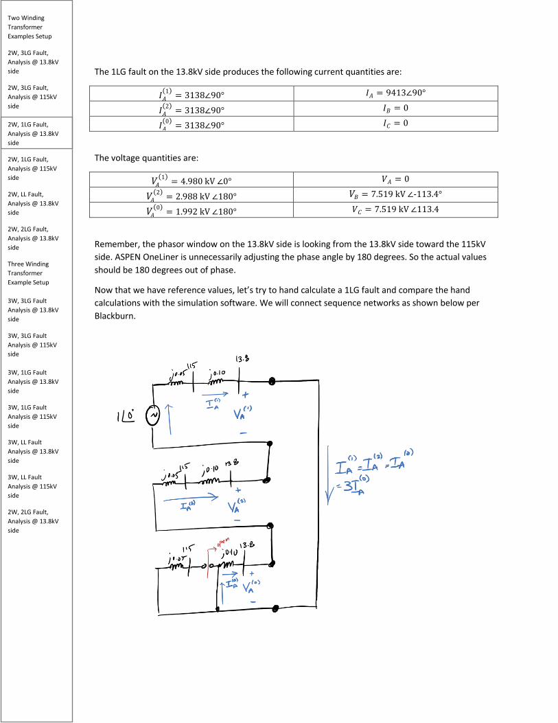
The 1LG fault on the 13.8kV side produces the following current quantities are:
𝐼𝐼𝑀𝑀(1) = 3138∠90° 𝐼𝐼𝑀𝑀 = 9413∠90°
𝐼𝐼𝑀𝑀(2) = 3138∠90° 𝐼𝐼𝐵𝐵 = 0
𝐼𝐼𝑀𝑀(0) = 3138∠90° 𝐼𝐼𝐶𝐶 = 0
The voltage quantities are:
𝑘𝑘𝑀𝑀(1) = 4.980 kV ∠0° 𝑘𝑘𝑀𝑀 = 0
𝑘𝑘𝑀𝑀(2) = 2.988 kV ∠180° 𝑘𝑘𝐵𝐵 = 7.519 kV ∠-113.4°
𝑘𝑘𝑀𝑀(0) = 1.992 kV ∠180° 𝑘𝑘𝐶𝐶 = 7.519 kV ∠113.4
Remember, the phasor window on the 13.8kV side is looking from the 13.8kV side toward the 115kV side. ASPEN OneLiner is unnecessarily adjusting the phase angle by 180 degrees. So the actual values should be 180 degrees out of phase.
Now that we have reference values, let’s try to hand calculate a 1LG fault and compare the hand calculations with the simulation software. We will connect sequence networks as shown below per Blackburn.
Two Winding Transformer Examples Setup
2W, 3LG Fault, Analysis @ 13.8kV side
2W, 3LG Fault, Analysis @ 115kV side 2W, 1LG Fault, Analysis @ 13.8kV side
2W, 1LG Fault, Analysis @ 115kV side
2W, LL Fault, Analysis @ 13.8kV side
2W, 2LG Fault, Analysis @ 13.8kV side
Three Winding Transformer Example Setup 3W, 3LG Fault Analysis @ 13.8kV side
3W, 3LG Fault Analysis @ 115kV side 3W, 1LG Fault Analysis @ 13.8kV side
3W, 1LG Fault Analysis @ 115kV side
3W, LL Fault Analysis @ 13.8kV side
3W, LL Fault Analysis @ 115kV side
2W, 2LG Fault, Analysis @ 13.8kV side
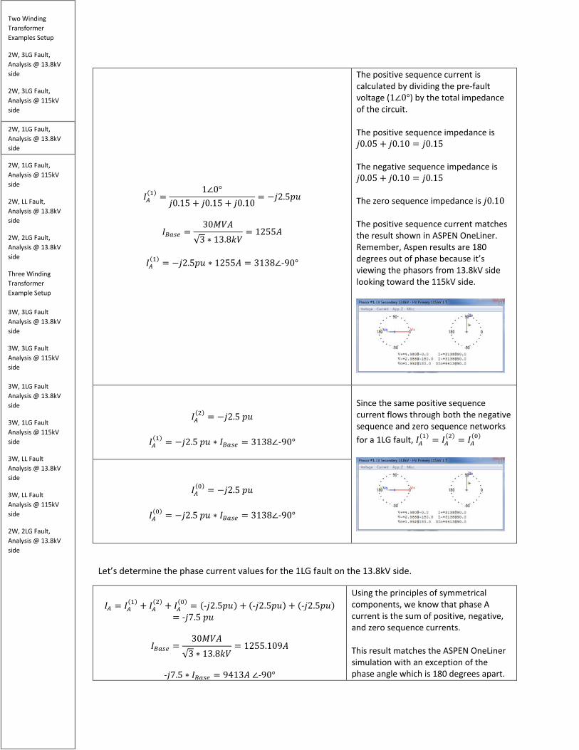
𝐼𝐼𝑀𝑀(1) =
1∠0°𝑗𝑗0.15 + 𝑗𝑗0.15 + 𝑗𝑗0.10
= −𝑗𝑗2.5𝑝𝑝𝑝𝑝
𝐼𝐼𝐵𝐵𝑏𝑏𝑠𝑠𝑏𝑏 =30𝑀𝑀𝑘𝑘𝑀𝑀
√3 ∗ 13.8𝑘𝑘𝑘𝑘= 1255𝑀𝑀
𝐼𝐼𝑀𝑀
(1) = −𝑗𝑗2.5𝑝𝑝𝑝𝑝 ∗ 1255𝑀𝑀 = 3138∠-90°
The positive sequence current is calculated by dividing the pre-fault voltage (1∠0°) by the total impedance of the circuit. The positive sequence impedance is 𝑗𝑗0.05 + 𝑗𝑗0.10 = 𝑗𝑗0.15 The negative sequence impedance is 𝑗𝑗0.05 + 𝑗𝑗0.10 = 𝑗𝑗0.15 The zero sequence impedance is 𝑗𝑗0.10 The positive sequence current matches the result shown in ASPEN OneLiner. Remember, Aspen results are 180 degrees out of phase because it’s viewing the phasors from 13.8kV side looking toward the 115kV side.
𝐼𝐼𝑀𝑀(2) = −𝑗𝑗2.5 𝑝𝑝𝑝𝑝
𝐼𝐼𝑀𝑀
(1) = −𝑗𝑗2.5 𝑝𝑝𝑝𝑝 ∗ 𝐼𝐼𝐵𝐵𝑏𝑏𝑠𝑠𝑏𝑏 = 3138∠-90°
Since the same positive sequence current flows through both the negative sequence and zero sequence networks for a 1LG fault, 𝐼𝐼𝑀𝑀
(1) = 𝐼𝐼𝑀𝑀(2) = 𝐼𝐼𝑀𝑀
(0)
𝐼𝐼𝑀𝑀
(0) = −𝑗𝑗2.5 𝑝𝑝𝑝𝑝
𝐼𝐼𝑀𝑀(0) = −𝑗𝑗2.5 𝑝𝑝𝑝𝑝 ∗ 𝐼𝐼𝐵𝐵𝑏𝑏𝑠𝑠𝑏𝑏 = 3138∠-90°
Let’s determine the phase current values for the 1LG fault on the 13.8kV side.
𝐼𝐼𝑀𝑀 = 𝐼𝐼𝑀𝑀
(1) + 𝐼𝐼𝑀𝑀(2) + 𝐼𝐼𝑀𝑀
(0) = (-𝑗𝑗2.5𝑝𝑝𝑝𝑝) + (-𝑗𝑗2.5𝑝𝑝𝑝𝑝) + (-𝑗𝑗2.5𝑝𝑝𝑝𝑝)= -𝑗𝑗7.5 𝑝𝑝𝑝𝑝
𝐼𝐼𝐵𝐵𝑏𝑏𝑠𝑠𝑏𝑏 =30𝑀𝑀𝑘𝑘𝑀𝑀
√3 ∗ 13.8𝑘𝑘𝑘𝑘= 1255.109𝑀𝑀
-𝑗𝑗7.5 ∗ 𝐼𝐼𝐵𝐵𝑏𝑏𝑠𝑠𝑏𝑏 = 9413𝑀𝑀 ∠-90°
Using the principles of symmetrical components, we know that phase A current is the sum of positive, negative, and zero sequence currents. This result matches the ASPEN OneLiner simulation with an exception of the phase angle which is 180 degrees apart.

Two Winding Transformer Examples Setup
2W, 3LG Fault, Analysis @ 13.8kV side
2W, 3LG Fault, Analysis @ 115kV side 2W, 1LG Fault, Analysis @ 13.8kV side
2W, 1LG Fault, Analysis @ 115kV side
2W, LL Fault, Analysis @ 13.8kV side
2W, 2LG Fault, Analysis @ 13.8kV side
Three Winding Transformer Example Setup 3W, 3LG Fault Analysis @ 13.8kV side
3W, 3LG Fault Analysis @ 115kV side 3W, 1LG Fault Analysis @ 13.8kV side
3W, 1LG Fault Analysis @ 115kV side
3W, LL Fault Analysis @ 13.8kV side
3W, LL Fault Analysis @ 115kV side
2W, 2LG Fault, Analysis @ 13.8kV side
Another way of representing phase A current is
3𝐼𝐼𝑀𝑀(0) = -𝑗𝑗7.5 𝑝𝑝𝑝𝑝 → 9413𝑀𝑀 ∠-90°
𝐼𝐼𝐵𝐵 = 𝑅𝑅2 ∗ 𝐼𝐼𝑀𝑀(1) + 𝑅𝑅 ∗ 𝐼𝐼𝑀𝑀
(2) + 𝐼𝐼𝑀𝑀(0)
𝐼𝐼𝐵𝐵 = (1∠240°)(-𝑗𝑗2.5) + (1∠120°)(-𝑗𝑗2.5) + (-𝑗𝑗2.5) = 0
𝐼𝐼𝐵𝐵 = 0
To calculate Phase B current, we must shift the positive sequence current by 240 degrees CCW and negative sequence current by 120 degrees CCW per fundamentals of symmetrical components. The total fault current on phase B equals 0 – this result makes sense because the fault is on phase A, so phase B should have no fault current. This result matches the ASPEN OneLiner simulation.
𝐼𝐼𝐶𝐶 = 𝑅𝑅 ∗ 𝐼𝐼𝑀𝑀(1) + 𝑅𝑅2 ∗ 𝐼𝐼𝑀𝑀
(2) + 𝐼𝐼𝑀𝑀(0)
𝐼𝐼𝐶𝐶 = (1∠120°)(-𝑗𝑗2.5) + (1∠240°)(-𝑗𝑗2.5) + (-𝑗𝑗2.5) = 0
A very similar operation for the phase C current also. We should expect phase C current because this is a 1LG on line A. This result matches the ASPEN OneLiner simulation.
Let’s determine the sequence voltages for the 1LG fault on the 13.8kV side.

Two Winding Transformer Examples Setup
2W, 3LG Fault, Analysis @ 13.8kV side
2W, 3LG Fault, Analysis @ 115kV side 2W, 1LG Fault, Analysis @ 13.8kV side
2W, 1LG Fault, Analysis @ 115kV side
2W, LL Fault, Analysis @ 13.8kV side
2W, 2LG Fault, Analysis @ 13.8kV side
Three Winding Transformer Example Setup 3W, 3LG Fault Analysis @ 13.8kV side
3W, 3LG Fault Analysis @ 115kV side 3W, 1LG Fault Analysis @ 13.8kV side
3W, 1LG Fault Analysis @ 115kV side
3W, LL Fault Analysis @ 13.8kV side
3W, LL Fault Analysis @ 115kV side
2W, 2LG Fault, Analysis @ 13.8kV side
𝑘𝑘𝑀𝑀(1) = 1 ∠0° − (j0.15)(−j2.5) = 0.625 pu
𝑘𝑘𝐵𝐵𝑏𝑏𝑠𝑠𝑏𝑏 =13.8kV√3
𝑘𝑘𝑀𝑀
(1) = (0.625 pu) ∗ 𝑘𝑘𝐵𝐵𝑏𝑏𝑠𝑠𝑏𝑏 = 4.98 kV∠0°
𝑘𝑘𝑀𝑀(1) = 4.98 kV∠0°
If we perform KVL around the positive sequence network and calculate the voltage at the point of the fault, we will always find it to equal the pre-fault voltage minus the positive sequence impedance times the positive sequence current. Notice that this is a positive voltage value so the angle is at 0 degrees. This is the same value as the ASPEN OneLiner simulation
𝑘𝑘𝑀𝑀(2) = 0 − (j0.15)(−j2.5) = −0.375 pu
𝑘𝑘𝑀𝑀(2) = (−0.375) ∗ �
13.8𝑘𝑘𝑘𝑘√3
� = 2.988 kV∠180°
𝑘𝑘𝑀𝑀
(2) = 2.988 kV∠180°
Similarly, performing KVL around the negative sequence network always gives us zero minus the negative sequence impedance multiplied by the negative sequence current. Note that negative sign which results in this case… this indicates the negative sequence voltage is 180 degrees out of phase compared to the positive sequence voltage. This is the same value as the ASPEN OneLiner simulation.
Two Winding Transformer Examples Setup
2W, 3LG Fault, Analysis @ 13.8kV side
2W, 3LG Fault, Analysis @ 115kV side 2W, 1LG Fault, Analysis @ 13.8kV side
2W, 1LG Fault, Analysis @ 115kV side
2W, LL Fault, Analysis @ 13.8kV side
2W, 2LG Fault, Analysis @ 13.8kV side
Three Winding Transformer Example Setup 3W, 3LG Fault Analysis @ 13.8kV side
3W, 3LG Fault Analysis @ 115kV side 3W, 1LG Fault Analysis @ 13.8kV side
3W, 1LG Fault Analysis @ 115kV side
3W, LL Fault Analysis @ 13.8kV side
3W, LL Fault Analysis @ 115kV side
2W, 2LG Fault, Analysis @ 13.8kV side
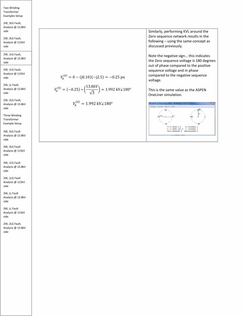
𝑘𝑘𝑀𝑀(0) = 0 − (j0.10)(−j2.5) = −0.25 pu
𝑘𝑘𝑀𝑀(0) = (−0.25) ∗ �
13.8𝑘𝑘𝑘𝑘√3
� = 1.992 kV∠180°
𝑘𝑘𝑀𝑀
(0) = 1.992 kV∠180°
Similarly, performing KVL around the Zero sequence network results in the following – using the same concept as discussed previously. Note the negative sign… this indicates the Zero sequence voltage is 180 degrees out of phase compared to the positive sequence voltage and in phase compared to the negative sequence voltage. This is the same value as the ASPEN OneLiner simulation.
Two Winding Transformer Examples Setup
2W, 3LG Fault, Analysis @ 13.8kV side
2W, 3LG Fault, Analysis @ 115kV side 2W, 1LG Fault, Analysis @ 13.8kV side
2W, 1LG Fault, Analysis @ 115kV side
2W, LL Fault, Analysis @ 13.8kV side
2W, 2LG Fault, Analysis @ 13.8kV side
Three Winding Transformer Example Setup 3W, 3LG Fault Analysis @ 13.8kV side
3W, 3LG Fault Analysis @ 115kV side 3W, 1LG Fault Analysis @ 13.8kV side
3W, 1LG Fault Analysis @ 115kV side
3W, LL Fault Analysis @ 13.8kV side
3W, LL Fault Analysis @ 115kV side
2W, 2LG Fault, Analysis @ 13.8kV side
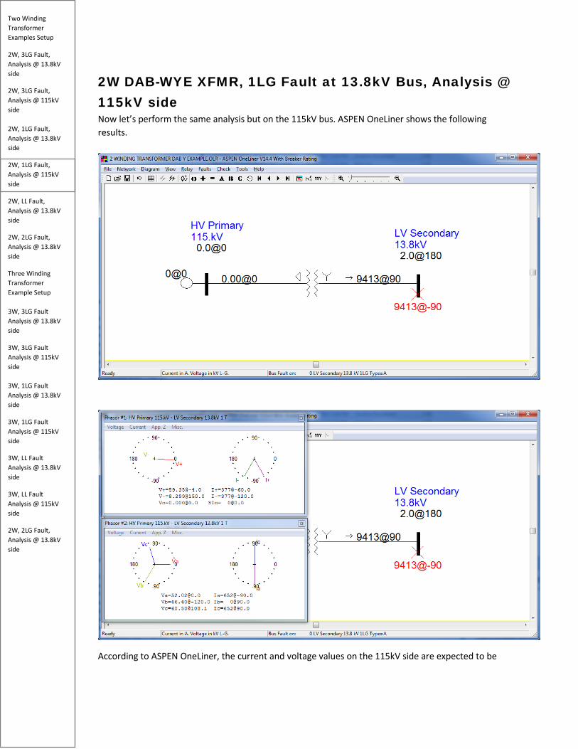
2W DAB-WYE XFMR, 1LG Fault at 13.8kV Bus, Analysis @ 115kV side Now let’s perform the same analysis but on the 115kV bus. ASPEN OneLiner shows the following results.
According to ASPEN OneLiner, the current and voltage values on the 115kV side are expected to be

Two Winding Transformer Examples Setup
2W, 3LG Fault, Analysis @ 13.8kV side
2W, 3LG Fault, Analysis @ 115kV side 2W, 1LG Fault, Analysis @ 13.8kV side
2W, 1LG Fault, Analysis @ 115kV side
2W, LL Fault, Analysis @ 13.8kV side
2W, 2LG Fault, Analysis @ 13.8kV side
Three Winding Transformer Example Setup 3W, 3LG Fault Analysis @ 13.8kV side
3W, 3LG Fault Analysis @ 115kV side 3W, 1LG Fault Analysis @ 13.8kV side
3W, 1LG Fault Analysis @ 115kV side
3W, LL Fault Analysis @ 13.8kV side
3W, LL Fault Analysis @ 115kV side
2W, 2LG Fault, Analysis @ 13.8kV side
𝑘𝑘𝑀𝑀(1) = 59.35 kV ∠-4.0° 𝐼𝐼𝑀𝑀
(1) = 377𝑀𝑀 ∠-60° 𝑘𝑘𝑀𝑀
(2) = 8.299 kV∠150° 𝐼𝐼𝑀𝑀(2) = 377A ∠-120°
𝑘𝑘𝑀𝑀(0) = 0 𝐼𝐼𝑀𝑀
(0) = 0 And the phase values on the 115kV side are expected to be
𝑘𝑘𝑀𝑀 = 52.02 kV ∠0° 𝐼𝐼𝑀𝑀 = 652 ∠-90° 𝑘𝑘𝐵𝐵 = 66.40 kV ∠-120° 𝐼𝐼𝐵𝐵 = 0 𝑘𝑘𝐶𝐶 = 60.50 kV ∠108.1° 𝐼𝐼𝐶𝐶 = 652 ∠90°
Now let’s calculate the sequence current quantities on the 115V side.
From the previous analysis, we know that -𝑗𝑗2.5 𝑝𝑝𝑝𝑝 flows on the LV Side Current of the transformer. However, because we have a DAB connection on the HV side, we need to take that into account.
𝐼𝐼𝑀𝑀(1) =
1∠0°𝑗𝑗0.40
= -𝑗𝑗2.5 𝑝𝑝𝑝𝑝 (𝐿𝐿𝑘𝑘 𝑆𝑆𝑇𝑇𝑎𝑎𝑅𝑅 𝑆𝑆𝑝𝑝𝑟𝑟𝑟𝑟𝑅𝑅𝑆𝑆𝑅𝑅)
𝐼𝐼𝐵𝐵𝑏𝑏𝑠𝑠𝑏𝑏 =30𝑀𝑀𝑘𝑘𝑀𝑀
√3 ∗ 115 𝑘𝑘𝑘𝑘= 150.613 A
𝐼𝐼𝑀𝑀
(1) = −𝑗𝑗2.5 ∗ 150.613 = 377 ∠-90° (𝐿𝐿𝑘𝑘 𝑆𝑆𝑇𝑇𝑎𝑎𝑅𝑅 𝑆𝑆𝑝𝑝𝑟𝑟𝑟𝑟𝑅𝑅𝑆𝑆𝑅𝑅) Because we know that the HV line current quantities LAGS the LV line current quantities by 30 degrees, we need to advance the HV quantities accordingly. For the DAB transformer specifically, we advance 30 degrees forward for positive sequence current and 30 degrees backward for negative sequence current.
The current that flows through the 115kV side is the same as the 13.8kV side. The only difference is that DAB-Wye-grounded transformer needs to be accounted for – both the magnitude and angle. A 1LG fault has only positive sequence, negative sequence, and zero sequence networks activated. If we adjusted only for the magnitude, we should expect the 115kV current to be phase A current on the 13.8kV side equals 377 𝑀𝑀∠-90° However, this is incorrect because we need to account for the DAB delta transformation. Because we know that the HV line current quantities LAG the LV line current quantities by 30 degrees, we need to advance the HV quantities accordingly by 30 degrees. 𝐼𝐼𝑀𝑀
(1) = (377 𝑀𝑀 ∠-90°) ∗ 1 ∠+30° Which gives us the 𝐼𝐼𝑀𝑀
(1) =(377 𝑀𝑀 ∠-60°) The hand-calculated value matches ASPEN OneLiner.

Two Winding Transformer Examples Setup
2W, 3LG Fault, Analysis @ 13.8kV side
2W, 3LG Fault, Analysis @ 115kV side 2W, 1LG Fault, Analysis @ 13.8kV side
2W, 1LG Fault, Analysis @ 115kV side
2W, LL Fault, Analysis @ 13.8kV side
2W, 2LG Fault, Analysis @ 13.8kV side
Three Winding Transformer Example Setup 3W, 3LG Fault Analysis @ 13.8kV side
3W, 3LG Fault Analysis @ 115kV side 3W, 1LG Fault Analysis @ 13.8kV side
3W, 1LG Fault Analysis @ 115kV side
3W, LL Fault Analysis @ 13.8kV side
3W, LL Fault Analysis @ 115kV side
2W, 2LG Fault, Analysis @ 13.8kV side
𝐼𝐼𝑀𝑀(1) = (377 𝑀𝑀∠-90°) ∗ (1 ∠+30°)
𝐼𝐼𝑀𝑀
(1) = 377 𝑀𝑀∠-60° (𝐻𝐻𝑘𝑘 𝑟𝑟𝑇𝑇𝑎𝑎𝑅𝑅 𝑆𝑆𝑝𝑝𝑟𝑟𝑟𝑟𝑅𝑅𝑆𝑆𝑅𝑅)
𝐼𝐼𝑀𝑀(2) = −𝑗𝑗2.5 ∗ 150.613 = 377 ∠-90° (𝐿𝐿𝑘𝑘 𝑆𝑆𝑇𝑇𝑎𝑎𝑅𝑅 𝑆𝑆𝑝𝑝𝑟𝑟𝑟𝑟𝑅𝑅𝑆𝑆𝑅𝑅)
𝐼𝐼𝑀𝑀
(2) = (377 𝑀𝑀∠-90°) ∗ (1 ∠-30°)
𝐼𝐼𝑀𝑀(2) = 377 𝑀𝑀∠-120° (𝐻𝐻𝑘𝑘 𝑟𝑟𝑇𝑇𝑎𝑎𝑅𝑅 𝑆𝑆𝑝𝑝𝑟𝑟𝑟𝑟𝑅𝑅𝑆𝑆𝑅𝑅)
The negative sequence current that flows through the 115kV side is the same as the 13.8kV side. The only difference is that DAB-Wye-grounded transformer needs to be accounted for. Remember, we must shift negative sequence backwards by 30 degrees because we have a DAB Wye-grounded transformer connection. The hand-calculated value matches ASPEN OneLiner.

Two Winding Transformer Examples Setup
2W, 3LG Fault, Analysis @ 13.8kV side
2W, 3LG Fault, Analysis @ 115kV side 2W, 1LG Fault, Analysis @ 13.8kV side
2W, 1LG Fault, Analysis @ 115kV side
2W, LL Fault, Analysis @ 13.8kV side
2W, 2LG Fault, Analysis @ 13.8kV side
Three Winding Transformer Example Setup 3W, 3LG Fault Analysis @ 13.8kV side
3W, 3LG Fault Analysis @ 115kV side 3W, 1LG Fault Analysis @ 13.8kV side
3W, 1LG Fault Analysis @ 115kV side
3W, LL Fault Analysis @ 13.8kV side
3W, LL Fault Analysis @ 115kV side
2W, 2LG Fault, Analysis @ 13.8kV side
𝐼𝐼𝑀𝑀
(0) = 0
Because we have a Delta transformer on the HV side, we know that zero sequence current is trapped within the delta and does not pass on the HV side. The hand-calculated value matches Aspen OneLiner.
The line current on the 115 kV side are calculated below.
𝐼𝐼𝑀𝑀 = 𝐼𝐼𝑀𝑀
(1) + 𝐼𝐼𝑀𝑀(2) = 377 𝑀𝑀∠-60° + 377 𝑀𝑀∠-120°
𝐼𝐼𝑀𝑀 = 652 A ∠-90°
Using the principles of symmetrical components, we know that phase A current is the sum of positive, negative, and zero sequence currents. However, since the zero sequence current is blocked, we omit the zero sequence current from our calculations. This matches the ASPEN OneLiner result.
Two Winding Transformer Examples Setup
2W, 3LG Fault, Analysis @ 13.8kV side
2W, 3LG Fault, Analysis @ 115kV side 2W, 1LG Fault, Analysis @ 13.8kV side
2W, 1LG Fault, Analysis @ 115kV side
2W, LL Fault, Analysis @ 13.8kV side
2W, 2LG Fault, Analysis @ 13.8kV side
Three Winding Transformer Example Setup 3W, 3LG Fault Analysis @ 13.8kV side
3W, 3LG Fault Analysis @ 115kV side 3W, 1LG Fault Analysis @ 13.8kV side
3W, 1LG Fault Analysis @ 115kV side
3W, LL Fault Analysis @ 13.8kV side
3W, LL Fault Analysis @ 115kV side
2W, 2LG Fault, Analysis @ 13.8kV side
𝐼𝐼𝐵𝐵 = 𝑅𝑅2 ∗ 𝐼𝐼𝑀𝑀
(1) + 𝑅𝑅 ∗ 𝐼𝐼𝑀𝑀(2) + 𝐼𝐼𝑀𝑀
(0) 𝐼𝐼𝐵𝐵 = (1∠240°)(377 𝑀𝑀∠-60°) + (1∠120°)(377 𝑀𝑀∠-120°)
𝐼𝐼𝐵𝐵 = 0
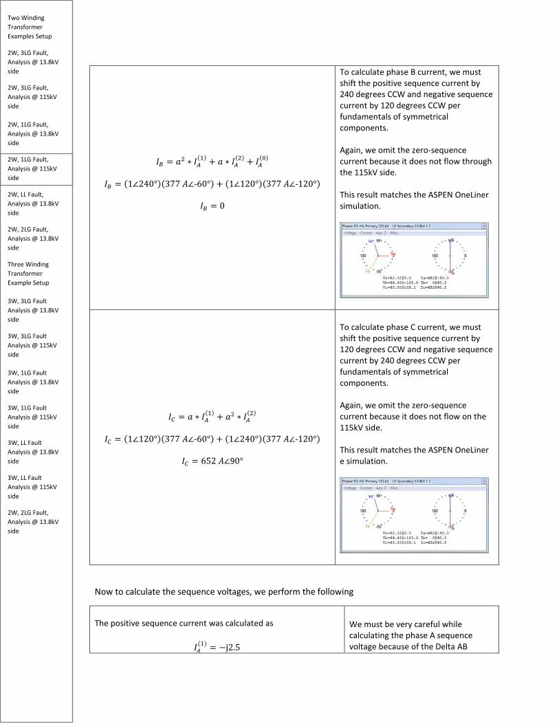
To calculate phase B current, we must shift the positive sequence current by 240 degrees CCW and negative sequence current by 120 degrees CCW per fundamentals of symmetrical components. Again, we omit the zero-sequence current because it does not flow through the 115kV side. This result matches the ASPEN OneLiner simulation.
𝐼𝐼𝐶𝐶 = 𝑅𝑅 ∗ 𝐼𝐼𝑀𝑀
(1) + 𝑅𝑅2 ∗ 𝐼𝐼𝑀𝑀(2)
𝐼𝐼𝐶𝐶 = (1∠120°)(377 𝑀𝑀∠-60°) + (1∠240°)(377 𝑀𝑀∠-120°)
𝐼𝐼𝐶𝐶 = 652 𝑀𝑀∠90°
To calculate phase C current, we must shift the positive sequence current by 120 degrees CCW and negative sequence current by 240 degrees CCW per fundamentals of symmetrical components. Again, we omit the zero-sequence current because it does not flow on the 115kV side. This result matches the ASPEN OneLiner e simulation.
Now to calculate the sequence voltages, we perform the following
The positive sequence current was calculated as
𝐼𝐼𝑀𝑀(1) = −j2.5
We must be very careful while calculating the phase A sequence voltage because of the Delta AB
Two Winding Transformer Examples Setup
2W, 3LG Fault, Analysis @ 13.8kV side
2W, 3LG Fault, Analysis @ 115kV side 2W, 1LG Fault, Analysis @ 13.8kV side
2W, 1LG Fault, Analysis @ 115kV side
2W, LL Fault, Analysis @ 13.8kV side
2W, 2LG Fault, Analysis @ 13.8kV side
Three Winding Transformer Example Setup 3W, 3LG Fault Analysis @ 13.8kV side
3W, 3LG Fault Analysis @ 115kV side 3W, 1LG Fault Analysis @ 13.8kV side
3W, 1LG Fault Analysis @ 115kV side
3W, LL Fault Analysis @ 13.8kV side
3W, LL Fault Analysis @ 115kV side
2W, 2LG Fault, Analysis @ 13.8kV side
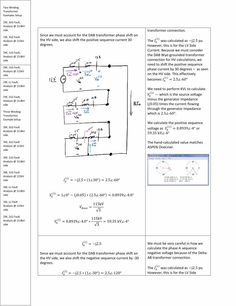
Since we must account for the DAB transformer phase shift on the HV side, we also shift the positive sequence current 30 degrees.
𝐼𝐼𝑀𝑀(1) = −j2.5 ∗ (1∠30°) = 2.5∠-60°
𝑘𝑘𝑀𝑀(1) = 1∠0° − (𝑗𝑗0.05) ∗ (2.5∠-60°) = 0.8939∠-4.0°
𝑘𝑘𝐵𝐵𝑏𝑏𝑠𝑠𝑏𝑏 =115kV√3
𝑘𝑘𝑀𝑀(1) = 0.8939∠-4.0° ∗
115kV√3
= 59.35 kV∠-4°
transformer connection. The 𝐼𝐼𝑀𝑀
(1) was calculated as −j2.5 pu However, this is for the LV Side Current. Because we must consider the DAB Wye-grounded transformer connection for HV calculations, we need to shift the positive sequence phase current by 30 degrees – as seen on the HV side. This effectively becomes 𝐼𝐼𝑀𝑀
(1) = 2.5∠-60° We need to perform KVL to calculate 𝑘𝑘𝑀𝑀
(1) --- which is the source voltage minus the generator impedance (𝑗𝑗0.05) times the current flowing through the generator impedance which is 2.5∠-60°. We calculate the positive sequence voltage as 𝑘𝑘𝑀𝑀
(1) = 0.8939∠-4° or 59.35 kV∠-4° The hand-calculated value matches ASPEN OneLiner.
𝐼𝐼𝑀𝑀
(1) = −j2.5 Since we must account for the DAB transformer phase shift on the HV side, we also shift the negative sequence current by -30 degrees.
𝐼𝐼𝑀𝑀(2) = −j2.5 ∗ (1∠-30°) = 2.5∠-120°
We must be very careful in how we calculate the phase A sequence negative voltage because of the Delta-AB transformer connection. The 𝐼𝐼𝑀𝑀
(1) was calculated as −j2.5 pu However, this is for the LV Side
Two Winding Transformer Examples Setup
2W, 3LG Fault, Analysis @ 13.8kV side
2W, 3LG Fault, Analysis @ 115kV side 2W, 1LG Fault, Analysis @ 13.8kV side
2W, 1LG Fault, Analysis @ 115kV side
2W, LL Fault, Analysis @ 13.8kV side
2W, 2LG Fault, Analysis @ 13.8kV side
Three Winding Transformer Example Setup 3W, 3LG Fault Analysis @ 13.8kV side
3W, 3LG Fault Analysis @ 115kV side 3W, 1LG Fault Analysis @ 13.8kV side
3W, 1LG Fault Analysis @ 115kV side
3W, LL Fault Analysis @ 13.8kV side
3W, LL Fault Analysis @ 115kV side
2W, 2LG Fault, Analysis @ 13.8kV side
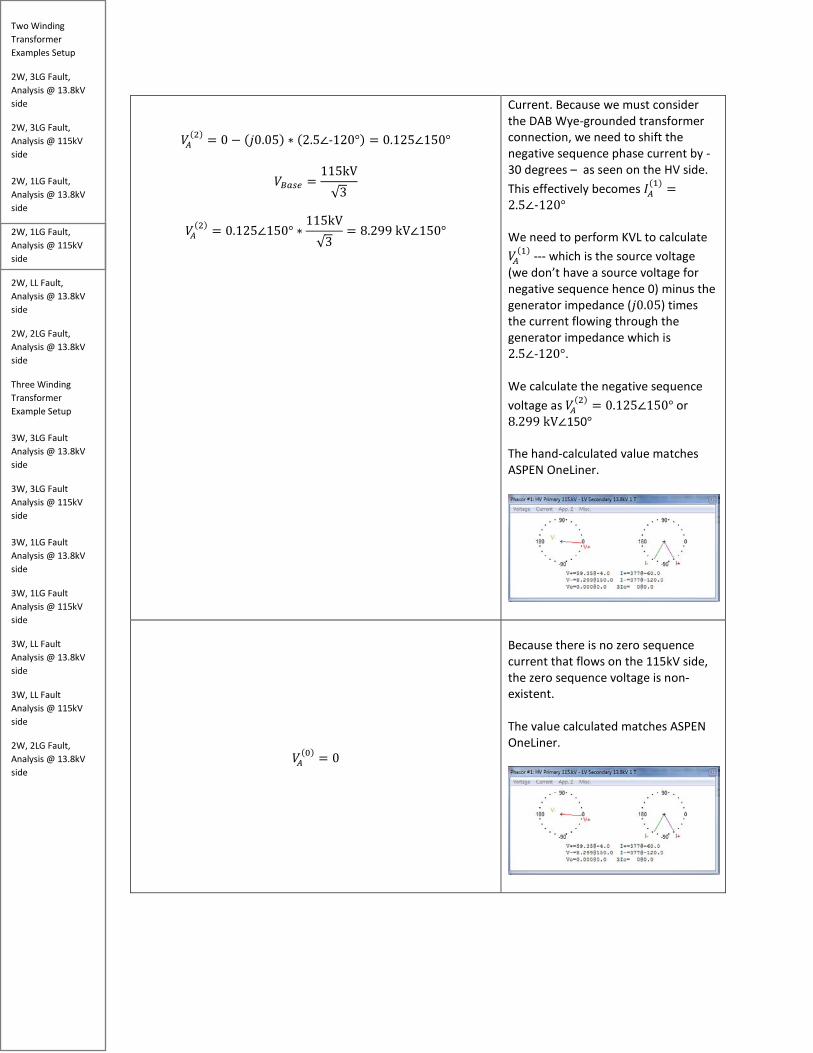
𝑘𝑘𝑀𝑀(2) = 0 − (𝑗𝑗0.05) ∗ (2.5∠-120°) = 0.125∠150°
𝑘𝑘𝐵𝐵𝑏𝑏𝑠𝑠𝑏𝑏 =115kV√3
𝑘𝑘𝑀𝑀(2) = 0.125∠150° ∗
115kV√3
= 8.299 kV∠150°
Current. Because we must consider the DAB Wye-grounded transformer connection, we need to shift the negative sequence phase current by -30 degrees – as seen on the HV side. This effectively becomes 𝐼𝐼𝑀𝑀
(1) =2.5∠-120° We need to perform KVL to calculate 𝑘𝑘𝑀𝑀
(1) --- which is the source voltage (we don’t have a source voltage for negative sequence hence 0) minus the generator impedance (𝑗𝑗0.05) times the current flowing through the generator impedance which is 2.5∠-120°. We calculate the negative sequence voltage as 𝑘𝑘𝑀𝑀
(2) = 0.125∠150° or 8.299 kV∠150° The hand-calculated value matches ASPEN OneLiner.
𝑘𝑘𝑀𝑀(0) = 0
Because there is no zero sequence current that flows on the 115kV side, the zero sequence voltage is non-existent. The value calculated matches ASPEN OneLiner.
Two Winding Transformer Examples Setup
2W, 3LG Fault, Analysis @ 13.8kV side
2W, 3LG Fault, Analysis @ 115kV side 2W, 1LG Fault, Analysis @ 13.8kV side
2W, 1LG Fault, Analysis @ 115kV side
2W, LL Fault, Analysis @ 13.8kV side
2W, 2LG Fault, Analysis @ 13.8kV side
Three Winding Transformer Example Setup 3W, 3LG Fault Analysis @ 13.8kV side
3W, 3LG Fault Analysis @ 115kV side 3W, 1LG Fault Analysis @ 13.8kV side
3W, 1LG Fault Analysis @ 115kV side
3W, LL Fault Analysis @ 13.8kV side
3W, LL Fault Analysis @ 115kV side
2W, 2LG Fault, Analysis @ 13.8kV side
Now to calculate the phase voltage quantities, we perform the following
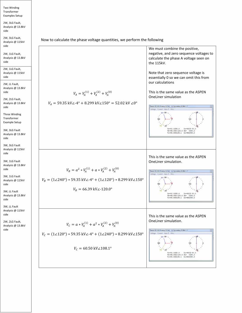
𝑘𝑘𝑀𝑀 = 𝑘𝑘𝑀𝑀(1) + 𝑘𝑘𝑀𝑀
(2) + 𝑘𝑘𝑀𝑀(0)
𝑘𝑘𝑀𝑀 = 59.35 kV∠-4° + 8.299 kV∠150° = 52.02 kV ∠0°
We must combine the positive, negative, and zero sequence voltages to calculate the phase A voltage seen on the 115kV. Note that zero sequence voltage is essentially 0 so we can omit this from our calculations This is the same value as the ASPEN OneLiner simulation
𝑘𝑘𝐵𝐵 = 𝑅𝑅2 ∗ 𝑘𝑘𝑀𝑀
(1) + 𝑅𝑅 ∗ 𝑘𝑘𝑀𝑀(2) + 𝑘𝑘𝑀𝑀
(0) 𝑘𝑘𝐵𝐵 = (1∠240°) ∗ 59.35 kV∠-4° + (1∠120°) ∗ 8.299 kV∠150°
𝑘𝑘𝐵𝐵 = 66.39 kV∠-120.0°
This is the same value as the ASPEN OneLiner simulation.
𝑘𝑘𝐶𝐶 = 𝑅𝑅 ∗ 𝑘𝑘𝑀𝑀(1) + 𝑅𝑅2 ∗ 𝑘𝑘𝑀𝑀
(2) + 𝑘𝑘𝑀𝑀(0)
𝑘𝑘𝐶𝐶 = (1∠120°) ∗ 59.35 kV∠-4° + (1∠240°) ∗ 8.299 kV∠150°
𝑘𝑘𝐶𝐶 = 60.50 kV∠108.1°
This is the same value as the ASPEN OneLiner simulation.

Two Winding Transformer Examples Setup
2W, 3LG Fault, Analysis @ 13.8kV side
2W, 3LG Fault, Analysis @ 115kV side 2W, 1LG Fault, Analysis @ 13.8kV side
2W, 1LG Fault, Analysis @ 115kV side
2W, LL Fault, Analysis @ 13.8kV side
2W, 2LG Fault, Analysis @ 13.8kV side
Three Winding Transformer Example Setup 3W, 3LG Fault Analysis @ 13.8kV side
3W, 3LG Fault Analysis @ 115kV side 3W, 1LG Fault Analysis @ 13.8kV side
3W, 1LG Fault Analysis @ 115kV side
3W, LL Fault Analysis @ 13.8kV side
3W, LL Fault Analysis @ 115kV side
2W, 2LG Fault, Analysis @ 13.8kV side
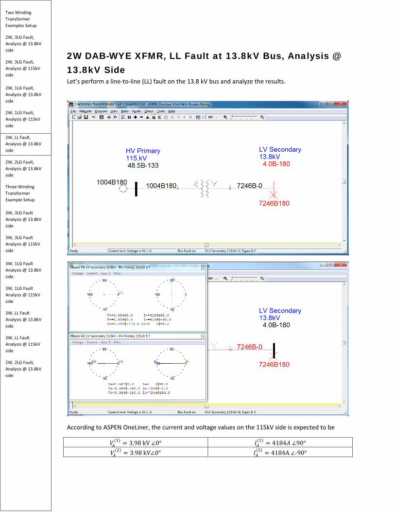
2W DAB-WYE XFMR, LL Fault at 13.8kV Bus, Analysis @ 13.8kV Side Let’s perform a line-to-line (LL) fault on the 13.8 kV bus and analyze the results.
According to ASPEN OneLiner, the current and voltage values on the 115kV side is expected to be
𝑘𝑘𝑀𝑀(1) = 3.98 kV ∠0° 𝐼𝐼𝑀𝑀
(1) = 4184𝑀𝑀 ∠90° 𝑘𝑘𝑀𝑀
(2) = 3.98 kV∠0° 𝐼𝐼𝑀𝑀(2) = 4184A ∠-90°

Two Winding Transformer Examples Setup
2W, 3LG Fault, Analysis @ 13.8kV side
2W, 3LG Fault, Analysis @ 115kV side 2W, 1LG Fault, Analysis @ 13.8kV side
2W, 1LG Fault, Analysis @ 115kV side
2W, LL Fault, Analysis @ 13.8kV side
2W, 2LG Fault, Analysis @ 13.8kV side
Three Winding Transformer Example Setup 3W, 3LG Fault Analysis @ 13.8kV side
3W, 3LG Fault Analysis @ 115kV side 3W, 1LG Fault Analysis @ 13.8kV side
3W, 1LG Fault Analysis @ 115kV side
3W, LL Fault Analysis @ 13.8kV side
3W, LL Fault Analysis @ 115kV side
2W, 2LG Fault, Analysis @ 13.8kV side
𝑘𝑘𝑀𝑀(0) = 0 𝐼𝐼𝑀𝑀
(0) = 0 And the phase values on the 115 kV side are expected to be
𝑘𝑘𝑀𝑀 = 7.98 kV ∠0° 𝐼𝐼𝑀𝑀 = 0 ∠0° 𝑘𝑘𝐵𝐵 = 3.98 kV ∠-180° 𝐼𝐼𝐵𝐵 = 7246 ∠0° 𝑘𝑘𝐶𝐶 = 3.98 kV ∠-180° 𝐼𝐼𝐶𝐶 = 7246 ∠180°
Now let’s calculate the sequence current quantities on the 115 V side.
𝐼𝐼𝑓𝑓𝑏𝑏(1) =
1∠0°𝑗𝑗0.05 + j0.10 + j0.10 + j0.05
= -𝑗𝑗3.333 𝑝𝑝𝑝𝑝 (𝐿𝐿𝑘𝑘 𝑆𝑆𝑇𝑇𝑎𝑎𝑅𝑅 𝑆𝑆𝑝𝑝𝑟𝑟𝑟𝑟𝑅𝑅𝑆𝑆𝑅𝑅)
𝐼𝐼𝐵𝐵𝑏𝑏𝑠𝑠𝑏𝑏 =30𝑀𝑀𝑘𝑘𝑀𝑀
√3 ∗ 13.8 𝑘𝑘𝑘𝑘= 1255.11 A
For a line to line fault, the positive and negative sequence network diagram is connected in parallel. The fault current is essentially the pre fault voltage divided by the total positive and negative sequence impedance. We adjust by the base current and get the following current for positive sequence phase a current on the LV Side Current. 𝐼𝐼𝑅𝑅
(1)
= 4184 ∠-90° (𝐿𝐿𝑘𝑘 𝑆𝑆𝑇𝑇𝑎𝑎𝑅𝑅 𝑆𝑆𝑝𝑝𝑟𝑟𝑟𝑟𝑅𝑅𝑆𝑆𝑅𝑅)
Two Winding Transformer Examples Setup
2W, 3LG Fault, Analysis @ 13.8kV side
2W, 3LG Fault, Analysis @ 115kV side 2W, 1LG Fault, Analysis @ 13.8kV side
2W, 1LG Fault, Analysis @ 115kV side
2W, LL Fault, Analysis @ 13.8kV side
2W, 2LG Fault, Analysis @ 13.8kV side
Three Winding Transformer Example Setup 3W, 3LG Fault Analysis @ 13.8kV side
3W, 3LG Fault Analysis @ 115kV side 3W, 1LG Fault Analysis @ 13.8kV side
3W, 1LG Fault Analysis @ 115kV side
3W, LL Fault Analysis @ 13.8kV side
3W, LL Fault Analysis @ 115kV side
2W, 2LG Fault, Analysis @ 13.8kV side
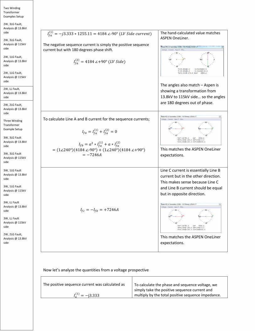
𝐼𝐼𝑓𝑓𝑏𝑏(1) = −𝑗𝑗3.333 ∗ 1255.11 = 4184 ∠-90° (𝐿𝐿𝑘𝑘 𝑆𝑆𝑇𝑇𝑎𝑎𝑅𝑅 𝑆𝑆𝑝𝑝𝑟𝑟𝑟𝑟𝑅𝑅𝑆𝑆𝑅𝑅)
The negative sequence current is simply the positive sequence current but with 180 degrees phase shift.
𝐼𝐼𝑓𝑓𝑏𝑏(2) = 4184 ∠+90° (𝐿𝐿𝑘𝑘 𝑆𝑆𝑇𝑇𝑎𝑎𝑅𝑅)
The hand-calculated value matches ASPEN OneLiner.
The angles also match – Aspen is showing a transformation from 13.8kV to 115kV side… so the angles are 180 degrees out of phase.
To calculate Line A and B current for the sequence currents;
𝐼𝐼𝑓𝑓𝑏𝑏 = 𝐼𝐼𝑓𝑓𝑏𝑏(1) + 𝐼𝐼𝑓𝑓𝑏𝑏
(2) = 0
𝐼𝐼𝑓𝑓𝑏𝑏 = 𝑅𝑅2 ∗ 𝐼𝐼𝑓𝑓𝑏𝑏(1) + 𝑅𝑅 ∗ 𝐼𝐼𝑓𝑓𝑏𝑏
(2) = (1∠240°)(4184 ∠-90°) + (1∠240°)(4184 ∠+90°)
= −7246𝑀𝑀
This matches the ASPEN OneLiner expectations.
𝐼𝐼𝑓𝑓𝑠𝑠 = −𝐼𝐼𝑓𝑓𝑏𝑏 = +7246𝑀𝑀
Line C current is essentially Line B current but in the other direction. This makes sense because Line C and Line B current should be equal but in opposite direction.
This matches the ASPEN OneLiner expectations.
Now let’s analyze the quantities from a voltage prospective
The positive sequence current was calculated as
𝐼𝐼𝑏𝑏(1) = −j3.333
To calculate the phase and sequence voltage, we simply take the positive sequence current and multiply by the total positive sequence impedance.

Two Winding Transformer Examples Setup
2W, 3LG Fault, Analysis @ 13.8kV side
2W, 3LG Fault, Analysis @ 115kV side 2W, 1LG Fault, Analysis @ 13.8kV side
2W, 1LG Fault, Analysis @ 115kV side
2W, LL Fault, Analysis @ 13.8kV side
2W, 2LG Fault, Analysis @ 13.8kV side
Three Winding Transformer Example Setup 3W, 3LG Fault Analysis @ 13.8kV side
3W, 3LG Fault Analysis @ 115kV side 3W, 1LG Fault Analysis @ 13.8kV side
3W, 1LG Fault Analysis @ 115kV side
3W, LL Fault Analysis @ 13.8kV side
3W, LL Fault Analysis @ 115kV side
2W, 2LG Fault, Analysis @ 13.8kV side
𝑘𝑘𝑏𝑏
(1) = 1∠0° − (𝑗𝑗0.15) ∗ (−j3.333) = 0.50∠0° pu
𝑘𝑘𝐵𝐵𝑏𝑏𝑠𝑠𝑏𝑏 =13.8kV√3
𝑘𝑘𝑏𝑏(1) = 0.50∠0° ∗
13.8kV√3
= 3.98 kV∠0°
𝑘𝑘𝑏𝑏
(2) = 𝑘𝑘𝑏𝑏(1) = 3.98 kV∠0°
𝑘𝑘𝑏𝑏
(0) = 0
𝑘𝑘𝑏𝑏 = 𝑘𝑘𝑏𝑏(1) + 𝑘𝑘𝑏𝑏
(2) + 𝑘𝑘𝑏𝑏(0)
= 3.98 kV∠0° + 3.98 kV∠0° + 0 = 7.96kV∠0°
This gives us the voltage drop across the generator and transformer impedance. Then we take the pre fault voltage and subtract by the voltage drop … that gives us positive sequence voltage value. It’s interesting to note that for a line to line fault, the positive sequence voltage is 0.50 per unit. The same is true for the negative sequence voltage. This allows us to mentally predict the voltage levels for any line to line fault. The phase 𝑘𝑘𝑏𝑏 voltage is simply the combination of all three sequence component. We get full rated voltage. This makes sense because the fault was on line B and line C. Line A was unaffected. The hand-calculated value matches ASPEN OneLiner.
𝑘𝑘𝑏𝑏 = 𝑅𝑅2 ∙ 𝑘𝑘𝑏𝑏
(1) ∗ 𝑅𝑅 ∙ 𝑘𝑘𝑏𝑏(2) + 𝑘𝑘𝑏𝑏
(0) = (1∠240°) ∙ 3.98 kV + (1∠120°) ∙ 3.98 kV + 0
𝑘𝑘𝑏𝑏 = −3.98 kV = 3.98 kV∠180°
𝑘𝑘𝑠𝑠 = 𝑘𝑘𝑏𝑏 = 3.98 kV∠180°
For a phase to phase fault, we see that the faulted phase has a voltage depression of 50% Due to the characteristics of a phase to phase fault, both of the faulted phases will have the same phase voltage. The value calculated matches ASPEN OneLiner.

Two Winding Transformer Examples Setup
2W, 3LG Fault, Analysis @ 13.8kV side
2W, 3LG Fault, Analysis @ 115kV side 2W, 1LG Fault, Analysis @ 13.8kV side
2W, 1LG Fault, Analysis @ 115kV side
2W, LL Fault, Analysis @ 13.8kV side
2W, 2LG Fault, Analysis @ 13.8kV side
Three Winding Transformer Example Setup 3W, 3LG Fault Analysis @ 13.8kV side
3W, 3LG Fault Analysis @ 115kV side 3W, 1LG Fault Analysis @ 13.8kV side
3W, 1LG Fault Analysis @ 115kV side
3W, LL Fault Analysis @ 13.8kV side
3W, LL Fault Analysis @ 115kV side
2W, 2LG Fault, Analysis @ 13.8kV side
2W DAB-WYE XFMR, 2LG Fault at 13.8kV Bus, Analysis @ 13.8kV Side
Let’s perform a 2LG fault on the 13.8 kV bus and analyze the results.

Two Winding Transformer Examples Setup
2W, 3LG Fault, Analysis @ 13.8kV side
2W, 3LG Fault, Analysis @ 115kV side 2W, 1LG Fault, Analysis @ 13.8kV side
2W, 1LG Fault, Analysis @ 115kV side
2W, LL Fault, Analysis @ 13.8kV side
2W, 2LG Fault, Analysis @ 13.8kV side
Three Winding Transformer Example Setup 3W, 3LG Fault Analysis @ 13.8kV side
3W, 3LG Fault Analysis @ 115kV side 3W, 1LG Fault Analysis @ 13.8kV side
3W, 1LG Fault Analysis @ 115kV side
3W, LL Fault Analysis @ 13.8kV side
3W, LL Fault Analysis @ 115kV side
2W, 2LG Fault, Analysis @ 13.8kV side
According to ASPEN OneLiner, the current and voltage values on the 13.8kV side is expected to be
𝑘𝑘𝑀𝑀(1) = 2.27 kV ∠0° 𝐼𝐼𝑀𝑀
(1) = 5977𝑀𝑀 ∠90° 𝑘𝑘𝑀𝑀
(2) = 2.27 kV ∠0° 𝐼𝐼𝑀𝑀(2) = 2391 ∠-90°
𝑘𝑘𝑀𝑀(0) = 2.27 kV ∠0° 𝐼𝐼𝑀𝑀
(0) = 10758A ∠-90° And the phase values on the 13.8kV side are expected to be
𝑘𝑘𝑀𝑀 = 6.83 kV ∠0° 𝐼𝐼𝑀𝑀 = 0 ∠0° 𝑘𝑘𝐵𝐵 = 0 kV∠0° 𝐼𝐼𝐵𝐵 = 9025A ∠-36.6° 𝑘𝑘𝐶𝐶 = 0 kV∠0° 𝐼𝐼𝐶𝐶 = 9025A ∠-143.4°

Two Winding Transformer Examples Setup
2W, 3LG Fault, Analysis @ 13.8kV side
2W, 3LG Fault, Analysis @ 115kV side 2W, 1LG Fault, Analysis @ 13.8kV side
2W, 1LG Fault, Analysis @ 115kV side
2W, LL Fault, Analysis @ 13.8kV side
2W, 2LG Fault, Analysis @ 13.8kV side
Three Winding Transformer Example Setup 3W, 3LG Fault Analysis @ 13.8kV side
3W, 3LG Fault Analysis @ 115kV side 3W, 1LG Fault Analysis @ 13.8kV side
3W, 1LG Fault Analysis @ 115kV side
3W, LL Fault Analysis @ 13.8kV side
3W, LL Fault Analysis @ 115kV side
2W, 2LG Fault, Analysis @ 13.8kV side
Now let’s calculate the sequence current quantities on the 13.8 kV side.
𝐼𝐼𝑓𝑓𝑏𝑏(1) =
𝑘𝑘𝑓𝑓
𝑍𝑍(1) + � 𝑍𝑍(2) ∙ 𝑍𝑍(0)
𝑍𝑍(2) + 𝑍𝑍(0)�
𝐼𝐼𝑓𝑓𝑏𝑏(1) =
1∠0°
𝑗𝑗0.15 + � 𝑗𝑗0.15 ∙ 𝑗𝑗0.10𝑗𝑗0.15 + 𝑗𝑗0.10�
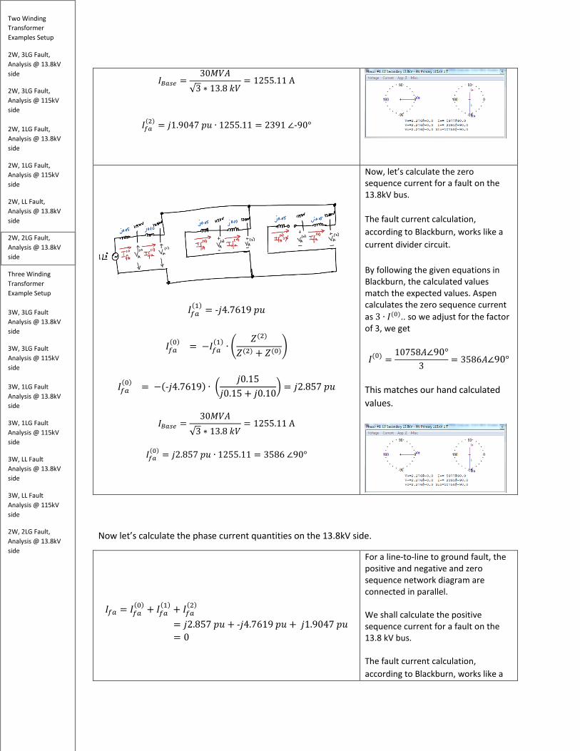
= -𝑗𝑗4.7619 𝑝𝑝𝑝𝑝 (𝐿𝐿𝑘𝑘 𝑆𝑆𝑇𝑇𝑎𝑎𝑅𝑅)
𝐼𝐼𝐵𝐵𝑏𝑏𝑠𝑠𝑏𝑏 =30𝑀𝑀𝑘𝑘𝑀𝑀
√3 ∗ 13.8 𝑘𝑘𝑘𝑘= 1255.11 A
𝐼𝐼𝑓𝑓𝑏𝑏
(1) = -𝑗𝑗4.7619 𝑝𝑝𝑝𝑝 ∙ 1255.11 = 5977 ∠-90°
For a line to line to ground fault, the positive, negative and zero sequence network diagram are connected in parallel. We shall calculate the positive sequence current for a fault on the 13.8 kV bus. The fault current calculation, according to Blackburn, works like a current divider circuit. By following the given equations in Blackburn, the calculated values match the expected values.
𝐼𝐼𝑓𝑓𝑏𝑏(1) = -𝑗𝑗4.7619 𝑝𝑝𝑝𝑝
𝐼𝐼𝑓𝑓𝑏𝑏(2) = −𝐼𝐼𝑓𝑓𝑏𝑏
(1) ∙ �𝑍𝑍(0)
𝑍𝑍(2) + 𝑍𝑍(0)�
𝐼𝐼𝑓𝑓𝑏𝑏(2) = −(-𝑗𝑗4.7619) ∙ �
𝑗𝑗0.10𝑗𝑗0.15 + 𝑗𝑗0.10
� = 𝑗𝑗1.9047 𝑝𝑝𝑝𝑝
Now, let’s calculate the negative sequence current for a fault on the 13.8 kV bus. The fault current calculation, according to Blackburn, works like a current divider circuit. By following the given equations in Blackburn, the calculated values match the expected values.
Two Winding Transformer Examples Setup
2W, 3LG Fault, Analysis @ 13.8kV side
2W, 3LG Fault, Analysis @ 115kV side 2W, 1LG Fault, Analysis @ 13.8kV side
2W, 1LG Fault, Analysis @ 115kV side
2W, LL Fault, Analysis @ 13.8kV side
2W, 2LG Fault, Analysis @ 13.8kV side
Three Winding Transformer Example Setup 3W, 3LG Fault Analysis @ 13.8kV side
3W, 3LG Fault Analysis @ 115kV side 3W, 1LG Fault Analysis @ 13.8kV side
3W, 1LG Fault Analysis @ 115kV side
3W, LL Fault Analysis @ 13.8kV side
3W, LL Fault Analysis @ 115kV side
2W, 2LG Fault, Analysis @ 13.8kV side
𝐼𝐼𝐵𝐵𝑏𝑏𝑠𝑠𝑏𝑏 =30𝑀𝑀𝑘𝑘𝑀𝑀
√3 ∗ 13.8 𝑘𝑘𝑘𝑘= 1255.11 A
𝐼𝐼𝑓𝑓𝑏𝑏(2) = 𝑗𝑗1.9047 𝑝𝑝𝑝𝑝 ∙ 1255.11 = 2391 ∠-90°
𝐼𝐼𝑓𝑓𝑏𝑏(1) = -𝑗𝑗4.7619 𝑝𝑝𝑝𝑝
𝐼𝐼𝑓𝑓𝑏𝑏(0) = −𝐼𝐼𝑓𝑓𝑏𝑏
(1) ∙ �𝑍𝑍(2)
𝑍𝑍(2) + 𝑍𝑍(0)�
𝐼𝐼𝑓𝑓𝑏𝑏(0) = −(-𝑗𝑗4.7619) ∙ �
𝑗𝑗0.15𝑗𝑗0.15 + 𝑗𝑗0.10
� = 𝑗𝑗2.857 𝑝𝑝𝑝𝑝
𝐼𝐼𝐵𝐵𝑏𝑏𝑠𝑠𝑏𝑏 =30𝑀𝑀𝑘𝑘𝑀𝑀
√3 ∗ 13.8 𝑘𝑘𝑘𝑘= 1255.11 A
𝐼𝐼𝑓𝑓𝑏𝑏
(0) = 𝑗𝑗2.857 𝑝𝑝𝑝𝑝 ∙ 1255.11 = 3586 ∠90°
Now, let’s calculate the zero sequence current for a fault on the 13.8kV bus. The fault current calculation, according to Blackburn, works like a current divider circuit. By following the given equations in Blackburn, the calculated values match the expected values. Aspen calculates the zero sequence current as 3 ∙ 𝐼𝐼(0).. so we adjust for the factor of 3, we get
𝐼𝐼(0) =10758𝑀𝑀∠90°
3= 3586𝑀𝑀∠90°
This matches our hand calculated values.
Now let’s calculate the phase current quantities on the 13.8kV side.
𝐼𝐼𝑓𝑓𝑏𝑏 = 𝐼𝐼𝑓𝑓𝑏𝑏
(0) + 𝐼𝐼𝑓𝑓𝑏𝑏(1) + 𝐼𝐼𝑓𝑓𝑏𝑏
(2) = 𝑗𝑗2.857 𝑝𝑝𝑝𝑝 + -𝑗𝑗4.7619 𝑝𝑝𝑝𝑝 + 𝑗𝑗1.9047 𝑝𝑝𝑝𝑝= 0
For a line-to-line to ground fault, the positive and negative and zero sequence network diagram are connected in parallel. We shall calculate the positive sequence current for a fault on the 13.8 kV bus. The fault current calculation, according to Blackburn, works like a
Two Winding Transformer Examples Setup
2W, 3LG Fault, Analysis @ 13.8kV side
2W, 3LG Fault, Analysis @ 115kV side 2W, 1LG Fault, Analysis @ 13.8kV side
2W, 1LG Fault, Analysis @ 115kV side
2W, LL Fault, Analysis @ 13.8kV side
2W, 2LG Fault, Analysis @ 13.8kV side
Three Winding Transformer Example Setup 3W, 3LG Fault Analysis @ 13.8kV side
3W, 3LG Fault Analysis @ 115kV side 3W, 1LG Fault Analysis @ 13.8kV side
3W, 1LG Fault Analysis @ 115kV side
3W, LL Fault Analysis @ 13.8kV side
3W, LL Fault Analysis @ 115kV side
2W, 2LG Fault, Analysis @ 13.8kV side
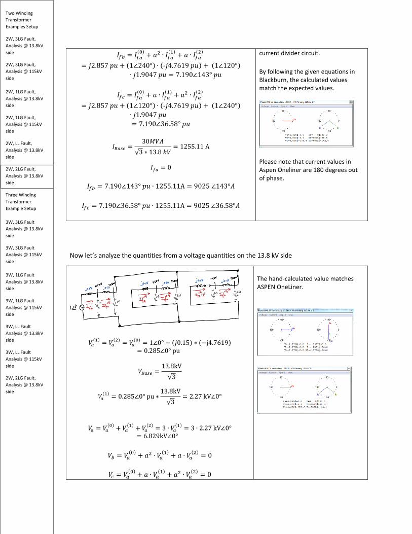
𝐼𝐼𝑓𝑓𝑏𝑏 = 𝐼𝐼𝑓𝑓𝑏𝑏(0) + 𝑅𝑅2 ∙ 𝐼𝐼𝑓𝑓𝑏𝑏
(1) + 𝑅𝑅 ∙ 𝐼𝐼𝑓𝑓𝑏𝑏(2)
= 𝑗𝑗2.857 𝑝𝑝𝑝𝑝 + (1∠240°) ∙ (-𝑗𝑗4.7619 𝑝𝑝𝑝𝑝) + (1∠120°)∙ 𝑗𝑗1.9047 𝑝𝑝𝑝𝑝 = 7.190∠143° 𝑝𝑝𝑝𝑝
𝐼𝐼𝑓𝑓𝑠𝑠 = 𝐼𝐼𝑓𝑓𝑏𝑏
(0) + 𝑅𝑅 ∙ 𝐼𝐼𝑓𝑓𝑏𝑏(1) + 𝑅𝑅2 ∙ 𝐼𝐼𝑓𝑓𝑏𝑏
(2) = 𝑗𝑗2.857 𝑝𝑝𝑝𝑝 + (1∠120°) ∙ (-𝑗𝑗4.7619 𝑝𝑝𝑝𝑝) + (1∠240°)
∙ 𝑗𝑗1.9047 𝑝𝑝𝑝𝑝 = 7.190∠36.58° 𝑝𝑝𝑝𝑝
𝐼𝐼𝐵𝐵𝑏𝑏𝑠𝑠𝑏𝑏 =30𝑀𝑀𝑘𝑘𝑀𝑀
√3 ∗ 13.8 𝑘𝑘𝑘𝑘= 1255.11 A
𝐼𝐼𝑓𝑓𝑅𝑅 = 0
𝐼𝐼𝑓𝑓𝑏𝑏 = 7.190∠143° 𝑝𝑝𝑝𝑝 ∙ 1255.11A = 9025 ∠143°𝑀𝑀
𝐼𝐼𝑓𝑓𝑠𝑠 = 7.190∠36.58° 𝑝𝑝𝑝𝑝 ∙ 1255.11A = 9025 ∠36.58°𝑀𝑀
current divider circuit. By following the given equations in Blackburn, the calculated values match the expected values.
Please note that current values in Aspen Oneliner are 180 degrees out of phase.
Now let’s analyze the quantities from a voltage quantities on the 13.8 kV side
𝑘𝑘𝑏𝑏(1) = 𝑘𝑘𝑏𝑏
(2) = 𝑘𝑘𝑏𝑏(0) = 1∠0° − (𝑗𝑗0.15) ∗ (−j4.7619)
= 0.285∠0° pu
𝑘𝑘𝐵𝐵𝑏𝑏𝑠𝑠𝑏𝑏 =13.8kV√3
𝑘𝑘𝑏𝑏(1) = 0.285∠0° pu ∗
13.8kV√3
= 2.27 kV∠0°
𝑘𝑘𝑏𝑏 = 𝑘𝑘𝑏𝑏(0) + 𝑘𝑘𝑏𝑏
(1) + 𝑘𝑘𝑏𝑏(2) = 3 ∙ 𝑘𝑘𝑏𝑏
(1) = 3 ∙ 2.27 kV∠0°= 6.829kV∠0°
𝑘𝑘𝑏𝑏 = 𝑘𝑘𝑏𝑏
(0) + 𝑅𝑅2 ∙ 𝑘𝑘𝑏𝑏(1) + 𝑅𝑅 ∙ 𝑘𝑘𝑏𝑏
(2) = 0
𝑘𝑘𝑠𝑠 = 𝑘𝑘𝑏𝑏(0) + 𝑅𝑅 ∙ 𝑘𝑘𝑏𝑏
(1) + 𝑅𝑅2 ∙ 𝑘𝑘𝑏𝑏(2) = 0
The hand-calculated value matches ASPEN OneLiner.
Two Winding Transformer Examples Setup
2W, 3LG Fault, Analysis @ 13.8kV side
2W, 3LG Fault, Analysis @ 115kV side 2W, 1LG Fault, Analysis @ 13.8kV side
2W, 1LG Fault, Analysis @ 115kV side
2W, LL Fault, Analysis @ 13.8kV side
2W, 2LG Fault, Analysis @ 13.8kV side
Three Winding Transformer Example Setup 3W, 3LG Fault Analysis @ 13.8kV side
3W, 3LG Fault Analysis @ 115kV side 3W, 1LG Fault Analysis @ 13.8kV side
3W, 1LG Fault Analysis @ 115kV side
3W, LL Fault Analysis @ 13.8kV side
3W, LL Fault Analysis @ 115kV side
2W, 2LG Fault, Analysis @ 13.8kV side
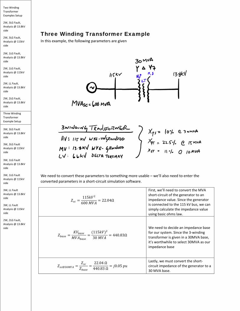
Three Winding Transformer Example In this example, the following parameters are given
We need to convert these parameters to something more usable – we’ll also need to enter the converted parameters in a short-circuit simulation software.
𝑍𝑍𝑠𝑠𝑠𝑠 =115𝑘𝑘𝑘𝑘2
600 𝑀𝑀𝑘𝑘𝑀𝑀= 22.04Ω
First, we’ll need to convert the MVA short-circuit of the generator to an impedance value. Since the generator is connected to the 115 kV bus, we can simply calculate the impedance value using basic ohms law.
𝑍𝑍𝑏𝑏𝑏𝑏𝑠𝑠𝑏𝑏 =𝐾𝐾𝑘𝑘𝑏𝑏𝑏𝑏𝑠𝑠𝑏𝑏𝑀𝑀𝑘𝑘𝑀𝑀𝑏𝑏𝑏𝑏𝑠𝑠𝑏𝑏
=(115𝑘𝑘𝑘𝑘)2
30 𝑀𝑀𝑘𝑘𝑀𝑀= 440.83Ω
We need to decide an impedance base for our system. Since the 3-winding transformer is given in a 30MVA base, it’s worthwhile to select 30MVA as our impedance base
𝑍𝑍𝑠𝑠𝑠𝑠@30𝑀𝑀𝑀𝑀𝑀𝑀 =𝑍𝑍𝑠𝑠𝑠𝑠𝑍𝑍𝑏𝑏𝑏𝑏𝑠𝑠𝑏𝑏
=22.04 Ω
440.83 Ω= 𝑗𝑗0.05 𝑝𝑝𝑝𝑝
Lastly, we must convert the short-circuit impedance of the generator to a 30 MVA base.

Two Winding Transformer Examples Setup
2W, 3LG Fault, Analysis @ 13.8kV side
2W, 3LG Fault, Analysis @ 115kV side 2W, 1LG Fault, Analysis @ 13.8kV side
2W, 1LG Fault, Analysis @ 115kV side
2W, LL Fault, Analysis @ 13.8kV side
2W, 2LG Fault, Analysis @ 13.8kV side
Three Winding Transformer Example Setup 3W, 3LG Fault Analysis @ 13.8kV side
3W, 3LG Fault Analysis @ 115kV side 3W, 1LG Fault Analysis @ 13.8kV side
3W, 1LG Fault Analysis @ 115kV side
3W, LL Fault Analysis @ 13.8kV side
3W, LL Fault Analysis @ 115kV side
2W, 2LG Fault, Analysis @ 13.8kV side
Typical three-winding transformer impedances are given in H, M, and L or high, medium, and low windings. The leakage impedance is given in ZHM, ZHL, and ZML – at different MVA and voltage ratings. For convenience, P, S, and T values are also used to signify primary, secondary, and tertiary. In this example, we will setup the transformer impedance like below.
𝑍𝑍𝐻𝐻𝑀𝑀 = 10% = 0.10𝑝𝑝𝑝𝑝 @30𝑀𝑀𝑘𝑘𝑀𝑀
𝑍𝑍𝐻𝐻𝑀𝑀 = 𝑍𝑍𝑝𝑝𝑠𝑠 = 𝑍𝑍𝑝𝑝𝑠𝑠@30𝑀𝑀𝑀𝑀 = 10% = 0.10𝑝𝑝𝑝𝑝
Given on a 30MVA base. Since we are working on a 30 MVA base, we do not need to convert this.
𝑍𝑍𝐻𝐻𝐿𝐿 = 𝑍𝑍𝑝𝑝𝑝𝑝 = 22.5% = 0.225𝑝𝑝𝑝𝑝 @15𝑀𝑀𝑘𝑘𝑀𝑀
𝑍𝑍𝐻𝐻𝐿𝐿 = 𝑍𝑍𝑝𝑝𝑝𝑝 = 0.225𝑝𝑝𝑝𝑝 ∗30𝑀𝑀𝑘𝑘𝑀𝑀15𝑀𝑀𝑘𝑘𝑀𝑀
= 0.45𝑝𝑝𝑝𝑝
Given on a 15MVA base. Since we are working on a 30 MVA base, we need to convert this value to a common MVA base as shown
𝑍𝑍𝑀𝑀𝐿𝐿 = 11% = 0.11𝑝𝑝𝑝𝑝 @10𝑀𝑀𝑘𝑘𝑀𝑀
𝑍𝑍𝑀𝑀𝐿𝐿 = 𝑍𝑍𝑠𝑠𝑝𝑝 = 0.11𝑝𝑝𝑝𝑝 ∗30𝑀𝑀𝑘𝑘𝑀𝑀10𝑀𝑀𝑘𝑘𝑀𝑀
= 0.33𝑝𝑝𝑝𝑝
Given on a 10MVA base. Since we are working on a 30 MVA base, we need to convert this value to a common MVA base as shown.
Building the 3W XFMR Short-circuit Model Now that we have calculated all the impedances to a common 30 MVA base, let’s model the system in ASPEN OneLiner short-circuit tool.
Two Winding Transformer Examples Setup
2W, 3LG Fault, Analysis @ 13.8kV side
2W, 3LG Fault, Analysis @ 115kV side 2W, 1LG Fault, Analysis @ 13.8kV side
2W, 1LG Fault, Analysis @ 115kV side
2W, LL Fault, Analysis @ 13.8kV side
2W, 2LG Fault, Analysis @ 13.8kV side
Three Winding Transformer Example Setup 3W, 3LG Fault Analysis @ 13.8kV side
3W, 3LG Fault Analysis @ 115kV side 3W, 1LG Fault Analysis @ 13.8kV side
3W, 1LG Fault Analysis @ 115kV side
3W, LL Fault Analysis @ 13.8kV side
3W, LL Fault Analysis @ 115kV side
2W, 2LG Fault, Analysis @ 13.8kV side
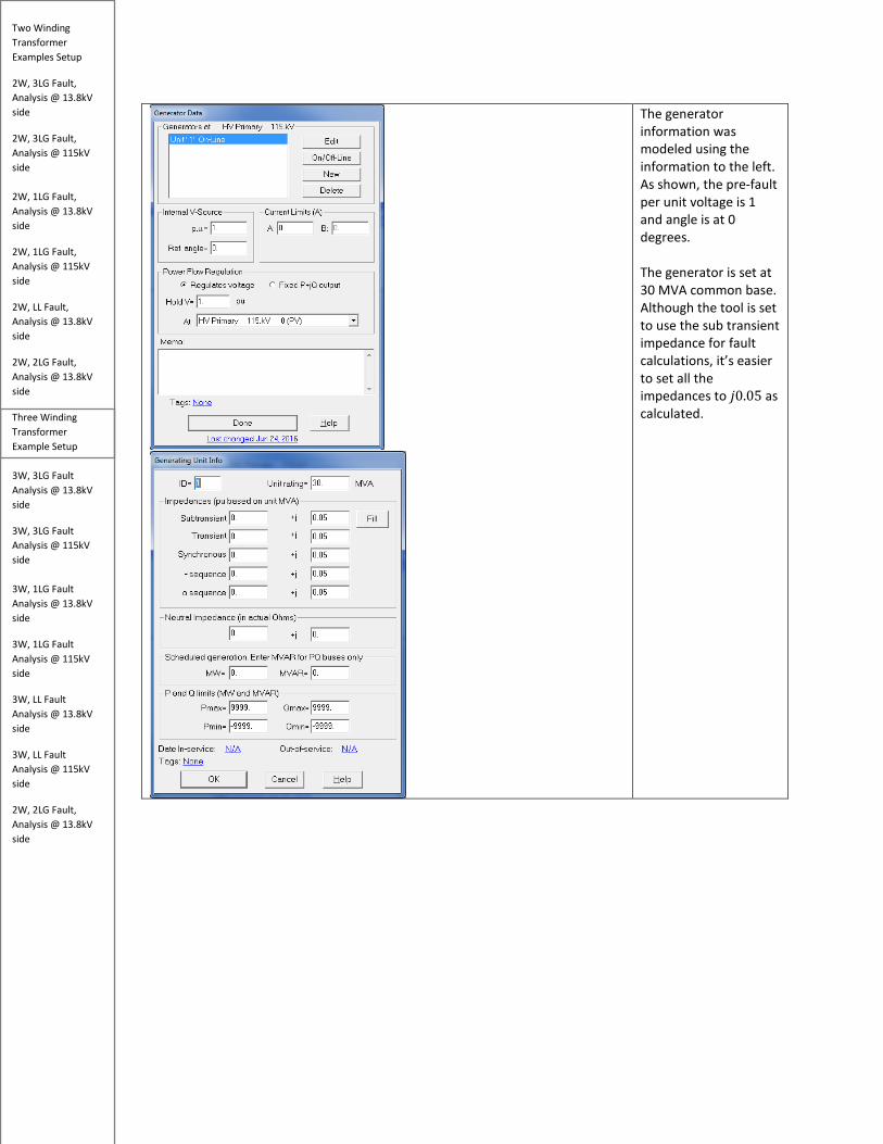
The generator information was modeled using the information to the left. As shown, the pre-fault per unit voltage is 1 and angle is at 0 degrees. The generator is set at 30 MVA common base. Although the tool is set to use the sub transient impedance for fault calculations, it’s easier to set all the impedances to 𝑗𝑗0.05 as calculated.

Two Winding Transformer Examples Setup
2W, 3LG Fault, Analysis @ 13.8kV side
2W, 3LG Fault, Analysis @ 115kV side 2W, 1LG Fault, Analysis @ 13.8kV side
2W, 1LG Fault, Analysis @ 115kV side
2W, LL Fault, Analysis @ 13.8kV side
2W, 2LG Fault, Analysis @ 13.8kV side
Three Winding Transformer Example Setup 3W, 3LG Fault Analysis @ 13.8kV side
3W, 3LG Fault Analysis @ 115kV side 3W, 1LG Fault Analysis @ 13.8kV side
3W, 1LG Fault Analysis @ 115kV side
3W, LL Fault Analysis @ 13.8kV side
3W, LL Fault Analysis @ 115kV side
2W, 2LG Fault, Analysis @ 13.8kV side
The 3 winding transformer is configured as shown. The primary voltage, secondary, and tertiary voltage is selected as the problem statement. The 30 MVA base rating is also selected. The 30 MVA base impedances are entered appropriately (Zps, Zpt, and Zst) for positive sequence short circuit impedance. Since the problem statement did not give the transformer zero sequence impedance values, appropriate values were chosen in its place. An effective infinite impedance is selected for Zg1 since the HV Wye winding is ungrounded connected (99999 + 99999j). An effective grounding impedance (0 + 0j) is selected for Zg2 since the LV Wye winding is grounded.
3W Xfmr Zero Sequence Connection The transformer manufacturer provided impedance values must be converted again to fit the parameters of the equivalent wye-type sequence network which will be used for the sequence impedance network. The following equation is used for this discussion (Equation A4.2-13 to 15 of Blackburn).

Two Winding Transformer Examples Setup
2W, 3LG Fault, Analysis @ 13.8kV side
2W, 3LG Fault, Analysis @ 115kV side 2W, 1LG Fault, Analysis @ 13.8kV side
2W, 1LG Fault, Analysis @ 115kV side
2W, LL Fault, Analysis @ 13.8kV side
2W, 2LG Fault, Analysis @ 13.8kV side
Three Winding Transformer Example Setup 3W, 3LG Fault Analysis @ 13.8kV side
3W, 3LG Fault Analysis @ 115kV side 3W, 1LG Fault Analysis @ 13.8kV side
3W, 1LG Fault Analysis @ 115kV side
3W, LL Fault Analysis @ 13.8kV side
3W, LL Fault Analysis @ 115kV side
2W, 2LG Fault, Analysis @ 13.8kV side
𝑍𝑍𝐻𝐻 =12
(𝑍𝑍𝐻𝐻𝑀𝑀 + 𝑍𝑍𝐻𝐻𝐿𝐿 − 𝑍𝑍𝑀𝑀𝐿𝐿) =12�𝑍𝑍𝑝𝑝𝑠𝑠 + 𝑍𝑍𝑝𝑝𝑝𝑝 − 𝑍𝑍𝑠𝑠𝑝𝑝� =
12
(0.10 + 0.45 − 0.33) = 0.11𝑝𝑝𝑝𝑝
𝑍𝑍𝑀𝑀 =12
(𝑍𝑍𝐻𝐻𝑀𝑀 + 𝑍𝑍𝑀𝑀𝐿𝐿 − 𝑍𝑍𝐻𝐻𝐿𝐿) =12�𝑍𝑍𝑝𝑝𝑠𝑠 + 𝑍𝑍𝑠𝑠𝑝𝑝 − 𝑍𝑍𝑝𝑝𝑝𝑝� =
12
(0.10 + 0.45 − 0.33) = −0.01𝑝𝑝𝑝𝑝
𝑍𝑍𝐿𝐿 =12
(𝑍𝑍𝐻𝐻𝐿𝐿 + 𝑍𝑍𝑀𝑀𝐿𝐿 − 𝑍𝑍𝐻𝐻𝑀𝑀) =12�𝑍𝑍𝑝𝑝𝑝𝑝 + 𝑍𝑍𝑠𝑠𝑝𝑝 − 𝑍𝑍𝑝𝑝𝑠𝑠� =
12
(0.45 + 0.33 − 0.10) = 0.34𝑝𝑝𝑝𝑝
It’s important to note that this 3W connection diagram is only valid for the positive and negative sequence impedance networks. The zero sequence connection will look very different due to the HV Wye-ungrounded connection and the LV delta tertiary connection both of which block the zero sequence current flow to ground.
According to Blackburn Figure A4.2-3, the zero sequence connections for the Wye-ungrounded (HV Primary winding) and Delta (LV Tertiary winding) are open. However, the MV secondary winding is closed.
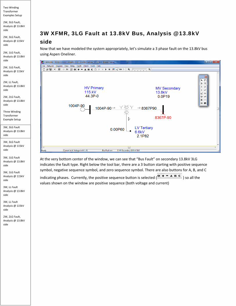
Two Winding Transformer Examples Setup
2W, 3LG Fault, Analysis @ 13.8kV side
2W, 3LG Fault, Analysis @ 115kV side 2W, 1LG Fault, Analysis @ 13.8kV side
2W, 1LG Fault, Analysis @ 115kV side
2W, LL Fault, Analysis @ 13.8kV side
2W, 2LG Fault, Analysis @ 13.8kV side
Three Winding Transformer Example Setup 3W, 3LG Fault Analysis @ 13.8kV side
3W, 3LG Fault Analysis @ 115kV side 3W, 1LG Fault Analysis @ 13.8kV side
3W, 1LG Fault Analysis @ 115kV side
3W, LL Fault Analysis @ 13.8kV side
3W, LL Fault Analysis @ 115kV side
2W, 2LG Fault, Analysis @ 13.8kV side
3W XFMR, 3LG Fault at 13.8kV Bus, Analysis @ 13.8kV side Now that we have modeled the system appropriately, let’s simulate a 3 phase fault on the 13.8kV bus using Aspen Oneliner.
At the very bottom center of the window, we can see that “Bus Fault” on secondary 13.8kV 3LG indicates the fault type. Right below the tool bar, there are a 3 button starting with positive sequence symbol, negative sequence symbol, and zero sequence symbol. There are also buttons for A, B, and C
indicating phases. Currently, the positive sequence button is selected ( ) so all the values shown on the window are positive sequence (both voltage and current)
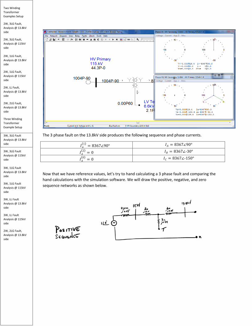
Two Winding Transformer Examples Setup
2W, 3LG Fault, Analysis @ 13.8kV side
2W, 3LG Fault, Analysis @ 115kV side 2W, 1LG Fault, Analysis @ 13.8kV side
2W, 1LG Fault, Analysis @ 115kV side
2W, LL Fault, Analysis @ 13.8kV side
2W, 2LG Fault, Analysis @ 13.8kV side
Three Winding Transformer Example Setup 3W, 3LG Fault Analysis @ 13.8kV side
3W, 3LG Fault Analysis @ 115kV side 3W, 1LG Fault Analysis @ 13.8kV side
3W, 1LG Fault Analysis @ 115kV side
3W, LL Fault Analysis @ 13.8kV side
3W, LL Fault Analysis @ 115kV side
2W, 2LG Fault, Analysis @ 13.8kV side
The 3 phase fault on the 13.8kV side produces the following sequence and phase currents.
𝐼𝐼𝑀𝑀(1) = 8367∠90° 𝐼𝐼𝑀𝑀 = 8367∠90°
𝐼𝐼𝑀𝑀(2) = 0 𝐼𝐼𝐵𝐵 = 8367∠-30°
𝐼𝐼𝑀𝑀(0) = 0 𝐼𝐼𝐶𝐶 = 8367∠-150°
Now that we have reference values, let’s try to hand calculating a 3 phase fault and comparing the hand calculations with the simulation software. We will draw the positive, negative, and zero sequence networks as shown below.
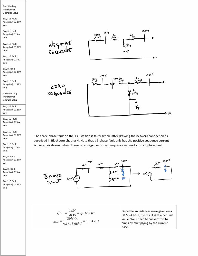
Two Winding Transformer Examples Setup
2W, 3LG Fault, Analysis @ 13.8kV side
2W, 3LG Fault, Analysis @ 115kV side 2W, 1LG Fault, Analysis @ 13.8kV side
2W, 1LG Fault, Analysis @ 115kV side
2W, LL Fault, Analysis @ 13.8kV side
2W, 2LG Fault, Analysis @ 13.8kV side
Three Winding Transformer Example Setup 3W, 3LG Fault Analysis @ 13.8kV side
3W, 3LG Fault Analysis @ 115kV side 3W, 1LG Fault Analysis @ 13.8kV side
3W, 1LG Fault Analysis @ 115kV side
3W, LL Fault Analysis @ 13.8kV side
3W, LL Fault Analysis @ 115kV side
2W, 2LG Fault, Analysis @ 13.8kV side
The three phase fault on the 13.8kV side is fairly simple after drawing the network connection as described in Blackburn chapter 4. Note that a 3 phase fault only has the positive sequence current activated as shown below. There is no negative or zero sequence networks for a 3 phase fault.
𝐼𝐼𝑀𝑀(1) =
1∠0°𝑗𝑗0.15
= -𝑗𝑗6.667 𝑝𝑝𝑝𝑝
𝐼𝐼𝐵𝐵𝑏𝑏𝑠𝑠𝑏𝑏 =30𝑀𝑀𝑘𝑘𝑀𝑀
√3 ∗ 13.08𝑘𝑘𝑘𝑘= 1324.20𝑀𝑀
Since the impedances were given on a 30 MVA base, the result is at a per unit value. We’ll need to convert this to amps by multiplying by the current base.

Two Winding Transformer Examples Setup
2W, 3LG Fault, Analysis @ 13.8kV side
2W, 3LG Fault, Analysis @ 115kV side 2W, 1LG Fault, Analysis @ 13.8kV side
2W, 1LG Fault, Analysis @ 115kV side
2W, LL Fault, Analysis @ 13.8kV side
2W, 2LG Fault, Analysis @ 13.8kV side
Three Winding Transformer Example Setup 3W, 3LG Fault Analysis @ 13.8kV side
3W, 3LG Fault Analysis @ 115kV side 3W, 1LG Fault Analysis @ 13.8kV side
3W, 1LG Fault Analysis @ 115kV side
3W, LL Fault Analysis @ 13.8kV side
3W, LL Fault Analysis @ 115kV side
2W, 2LG Fault, Analysis @ 13.8kV side
𝐼𝐼𝑀𝑀(1) = −𝑗𝑗6.667 ∗ 1324.20 = 8367𝑀𝑀 ∠-90°
This matches ASPEN OneLiner with an exception of the angle which is 180 degrees apart.
𝐼𝐼𝑀𝑀
(2) = 0
Since the negative and zero sequence networks are not activated for 3 phase faults, the negative and zero sequence currents both equal zero.
𝐼𝐼𝑀𝑀
(0) = 0
Now, let’s calculate the phase current values and see if they compare with ASPEN OneLiner. Because 3 phase faults are balanced, we will use the principles of symmetrical components to calculate the phase B and phase C currents.
𝐼𝐼𝑀𝑀
(1) = −𝑗𝑗6.667 ∗ 1324.20 = 8367𝑀𝑀 ∠-90°
This was calculated previously and
shown here for convenience.
𝐼𝐼𝐵𝐵 = 𝑅𝑅2 ∙ 𝐼𝐼𝑀𝑀
(1) + 𝑅𝑅 ∙ 𝐼𝐼𝑀𝑀(2) + 𝐼𝐼𝑀𝑀
(0)
Since 𝐼𝐼𝑀𝑀(2)𝑅𝑅𝑆𝑆𝑎𝑎 𝐼𝐼𝑀𝑀
(0)are both 0 for a 3 phase fault, the equation simplifies to
𝐼𝐼𝐵𝐵 = 𝑅𝑅2 ∙ 𝐼𝐼𝑀𝑀(1)

Two Winding Transformer Examples Setup
2W, 3LG Fault, Analysis @ 13.8kV side
2W, 3LG Fault, Analysis @ 115kV side 2W, 1LG Fault, Analysis @ 13.8kV side
2W, 1LG Fault, Analysis @ 115kV side
2W, LL Fault, Analysis @ 13.8kV side
2W, 2LG Fault, Analysis @ 13.8kV side
Three Winding Transformer Example Setup 3W, 3LG Fault Analysis @ 13.8kV side
3W, 3LG Fault Analysis @ 115kV side 3W, 1LG Fault Analysis @ 13.8kV side
3W, 1LG Fault Analysis @ 115kV side
3W, LL Fault Analysis @ 13.8kV side
3W, LL Fault Analysis @ 115kV side
2W, 2LG Fault, Analysis @ 13.8kV side
𝐼𝐼𝐵𝐵 = 𝑅𝑅2 ∙ 𝐼𝐼𝑀𝑀(1) = (1∠240°) ∗ (8367𝑀𝑀 ∠ − 90°)
= 8367𝑀𝑀 ∠150°
This matches ASPEN OneLiner expectations with an exception of 180 degree out of phase. So if we take -30 degrees (phase B line current as shown below) and add 180 degrees, we get 150 degrees which matches our hand calculations
𝐼𝐼𝐶𝐶 = a ∙ 𝐼𝐼𝑀𝑀
(1) + 𝑅𝑅2 ∙ 𝐼𝐼𝑀𝑀(2) + 𝐼𝐼𝑀𝑀
(0)
𝐼𝐼𝐶𝐶 = a ∙ 𝐼𝐼𝑀𝑀(1) = (1∠120°) ∗ (8367𝑀𝑀 ∠ − 90°) = 8367𝑀𝑀 ∠30°
Since 𝐼𝐼𝑀𝑀(2)𝑅𝑅𝑆𝑆𝑎𝑎 𝐼𝐼𝑀𝑀
(0)are both 0 for a 3 phase fault, the equation simplifies to 𝐼𝐼𝐶𝐶 = a ∙ 𝐼𝐼𝑀𝑀
(1)
This matches ASPEN OneLiner expectations with an exception of 180 degree out of phase. So if we take -150 degrees (phase C line current as shown below) and add 180 degrees, we get 30 degrees which matches our hand calculations
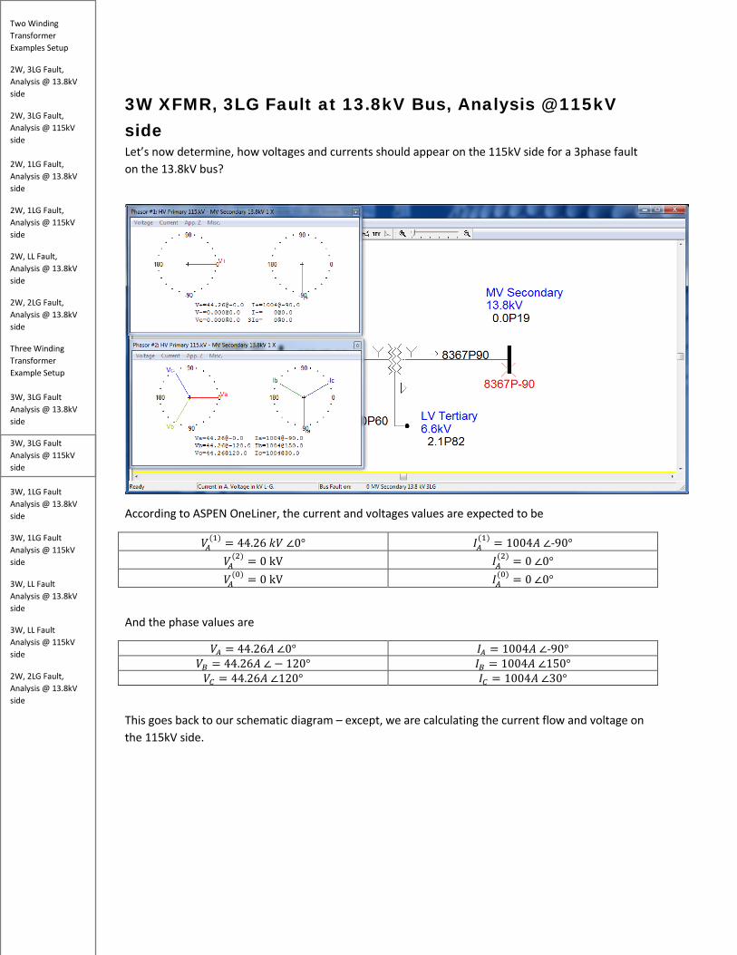
Two Winding Transformer Examples Setup
2W, 3LG Fault, Analysis @ 13.8kV side
2W, 3LG Fault, Analysis @ 115kV side 2W, 1LG Fault, Analysis @ 13.8kV side
2W, 1LG Fault, Analysis @ 115kV side
2W, LL Fault, Analysis @ 13.8kV side
2W, 2LG Fault, Analysis @ 13.8kV side
Three Winding Transformer Example Setup 3W, 3LG Fault Analysis @ 13.8kV side
3W, 3LG Fault Analysis @ 115kV side 3W, 1LG Fault Analysis @ 13.8kV side
3W, 1LG Fault Analysis @ 115kV side
3W, LL Fault Analysis @ 13.8kV side
3W, LL Fault Analysis @ 115kV side
2W, 2LG Fault, Analysis @ 13.8kV side
3W XFMR, 3LG Fault at 13.8kV Bus, Analysis @ 115kV side Let’s now determine, how voltages and currents should appear on the 115kV side for a 3phase fault on the 13.8kV bus?
According to ASPEN OneLiner, the current and voltages values are expected to be
𝑘𝑘𝑀𝑀(1) = 44.26 𝑘𝑘𝑘𝑘 ∠0° 𝐼𝐼𝑀𝑀
(1) = 1004𝑀𝑀 ∠-90° 𝑘𝑘𝑀𝑀
(2) = 0 kV 𝐼𝐼𝑀𝑀(2) = 0 ∠0°
𝑘𝑘𝑀𝑀(0) = 0 kV 𝐼𝐼𝑀𝑀
(0) = 0 ∠0°
And the phase values are
𝑘𝑘𝑀𝑀 = 44.26𝑀𝑀 ∠0° 𝐼𝐼𝑀𝑀 = 1004𝑀𝑀 ∠-90° 𝑘𝑘𝐵𝐵 = 44.26𝑀𝑀 ∠ − 120° 𝐼𝐼𝐵𝐵 = 1004𝑀𝑀 ∠150° 𝑘𝑘𝐶𝐶 = 44.26𝑀𝑀 ∠120° 𝐼𝐼𝐶𝐶 = 1004𝑀𝑀 ∠30°
This goes back to our schematic diagram – except, we are calculating the current flow and voltage on the 115kV side.
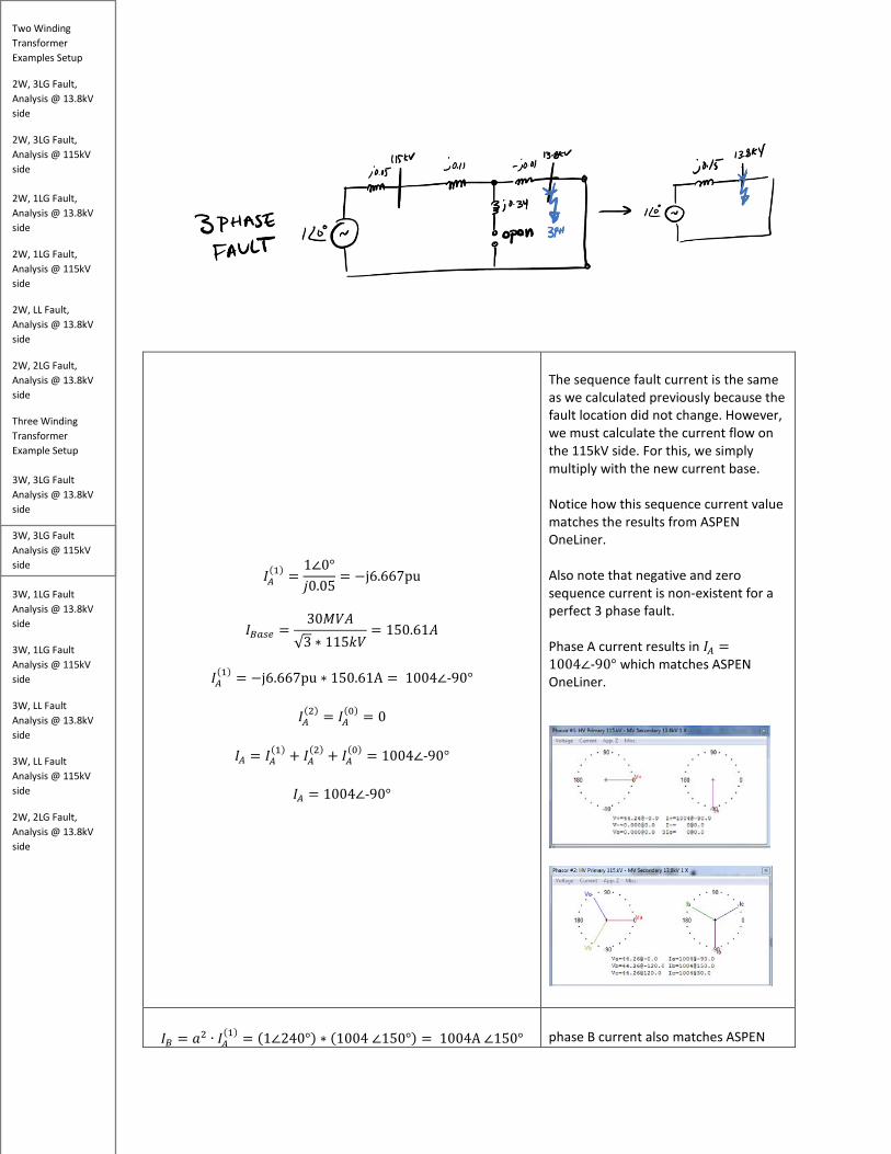
Two Winding Transformer Examples Setup
2W, 3LG Fault, Analysis @ 13.8kV side
2W, 3LG Fault, Analysis @ 115kV side 2W, 1LG Fault, Analysis @ 13.8kV side
2W, 1LG Fault, Analysis @ 115kV side
2W, LL Fault, Analysis @ 13.8kV side
2W, 2LG Fault, Analysis @ 13.8kV side
Three Winding Transformer Example Setup 3W, 3LG Fault Analysis @ 13.8kV side
3W, 3LG Fault Analysis @ 115kV side 3W, 1LG Fault Analysis @ 13.8kV side
3W, 1LG Fault Analysis @ 115kV side
3W, LL Fault Analysis @ 13.8kV side
3W, LL Fault Analysis @ 115kV side
2W, 2LG Fault, Analysis @ 13.8kV side
𝐼𝐼𝑀𝑀(1) =
1∠0°𝑗𝑗0.05
= −j6.667pu
𝐼𝐼𝐵𝐵𝑏𝑏𝑠𝑠𝑏𝑏 =30𝑀𝑀𝑘𝑘𝑀𝑀
√3 ∗ 115𝑘𝑘𝑘𝑘= 150.61𝑀𝑀
𝐼𝐼𝑀𝑀
(1) = −j6.667pu ∗ 150.61A = 1004∠-90°
𝐼𝐼𝑀𝑀(2) = 𝐼𝐼𝑀𝑀
(0) = 0
𝐼𝐼𝑀𝑀 = 𝐼𝐼𝑀𝑀(1) + 𝐼𝐼𝑀𝑀
(2) + 𝐼𝐼𝑀𝑀(0) = 1004∠-90°
𝐼𝐼𝑀𝑀 = 1004∠-90°
The sequence fault current is the same as we calculated previously because the fault location did not change. However, we must calculate the current flow on the 115kV side. For this, we simply multiply with the new current base. Notice how this sequence current value matches the results from ASPEN OneLiner. Also note that negative and zero sequence current is non-existent for a perfect 3 phase fault. Phase A current results in 𝐼𝐼𝑀𝑀 =1004∠-90° which matches ASPEN OneLiner.
𝐼𝐼𝐵𝐵 = 𝑅𝑅2 ∙ 𝐼𝐼𝑀𝑀
(1) = (1∠240°) ∗ (1004 ∠150°) = 1004A ∠150° phase B current also matches ASPEN

Two Winding Transformer Examples Setup
2W, 3LG Fault, Analysis @ 13.8kV side
2W, 3LG Fault, Analysis @ 115kV side 2W, 1LG Fault, Analysis @ 13.8kV side
2W, 1LG Fault, Analysis @ 115kV side
2W, LL Fault, Analysis @ 13.8kV side
2W, 2LG Fault, Analysis @ 13.8kV side
Three Winding Transformer Example Setup 3W, 3LG Fault Analysis @ 13.8kV side
3W, 3LG Fault Analysis @ 115kV side 3W, 1LG Fault Analysis @ 13.8kV side
3W, 1LG Fault Analysis @ 115kV side
3W, LL Fault Analysis @ 13.8kV side
3W, LL Fault Analysis @ 115kV side
2W, 2LG Fault, Analysis @ 13.8kV side
𝐼𝐼𝐵𝐵 = 1004A ∠150°
OneLiner at 𝐼𝐼𝐵𝐵 = 1004A ∠150°
𝐼𝐼𝐶𝐶 = a ∙ 𝐼𝐼𝑀𝑀(1) = (1∠120°) ∗ (1004 ∠150°) = 1004A ∠30°
Phase C current also matches ASPEN OneLiner at 𝐼𝐼𝐶𝐶 = 1004A ∠30°
Now to calculate the sequence and phase voltages:
𝑘𝑘𝑀𝑀
(1) = 1∠0° − (j0.05) ∗ (−j6.667) = 0.667pu
𝑘𝑘𝐵𝐵𝑏𝑏𝑠𝑠𝑏𝑏 =115kV√3
𝑘𝑘𝑀𝑀(1) = 0.667pu ∗
115kV√3
= 44.28kV∠0°
𝑘𝑘𝑀𝑀
(2) = 𝑘𝑘𝑀𝑀(0) = 0
𝑘𝑘𝑀𝑀 = 𝑘𝑘𝑀𝑀
(1) + 𝑘𝑘𝑀𝑀(2) + 𝑘𝑘𝑀𝑀
(0) = 44.28kV∠0°
Since negative and zero sequence networks do not exist, the negative and zero sequence voltages are also zero. Therefore, the phase A voltage is simply 𝑘𝑘𝑀𝑀 = 44.28kV∠0°
𝑘𝑘𝐵𝐵 = 𝑅𝑅2 ∙ 𝑘𝑘𝑀𝑀
(1) = (1∠240°) ∗ (44.28kV∠0°)= 44.28kV∠240°
As discussed earlier, since this is a balanced three phase fault, all the phase currents will have equal magnitude and displaced by 120 degrees, and

Two Winding Transformer Examples Setup
2W, 3LG Fault, Analysis @ 13.8kV side
2W, 3LG Fault, Analysis @ 115kV side 2W, 1LG Fault, Analysis @ 13.8kV side
2W, 1LG Fault, Analysis @ 115kV side
2W, LL Fault, Analysis @ 13.8kV side
2W, 2LG Fault, Analysis @ 13.8kV side
Three Winding Transformer Example Setup 3W, 3LG Fault Analysis @ 13.8kV side
3W, 3LG Fault Analysis @ 115kV side 3W, 1LG Fault Analysis @ 13.8kV side
3W, 1LG Fault Analysis @ 115kV side
3W, LL Fault Analysis @ 13.8kV side
3W, LL Fault Analysis @ 115kV side
2W, 2LG Fault, Analysis @ 13.8kV side
𝑘𝑘𝐵𝐵 = 44.28kV∠240°
since negative and zero sequence do not exist for three phase faults, we rotate the positive sequence voltage by 240 degrees in the CCW direction to get phase B voltage. The value calculated matches ASPEN OneLiner.
𝑘𝑘𝐶𝐶 = a ∙ 𝑘𝑘𝑀𝑀(1) = (1∠120°) ∗ (44.28kV∠0°)
= 44.28kV∠120°
𝑘𝑘𝐶𝐶 = 44.28kV∠120°
We rotate positive sequence A by 120 degrees in the CCW direction to get phase C voltage. The value calculated matches ASPEN OneLiner.

Two Winding Transformer Examples Setup
2W, 3LG Fault, Analysis @ 13.8kV side
2W, 3LG Fault, Analysis @ 115kV side 2W, 1LG Fault, Analysis @ 13.8kV side
2W, 1LG Fault, Analysis @ 115kV side
2W, LL Fault, Analysis @ 13.8kV side
2W, 2LG Fault, Analysis @ 13.8kV side
Three Winding Transformer Example Setup 3W, 3LG Fault Analysis @ 13.8kV side
3W, 3LG Fault Analysis @ 115kV side 3W, 1LG Fault Analysis @ 13.8kV side
3W, 1LG Fault Analysis @ 115kV side
3W, LL Fault Analysis @ 13.8kV side
3W, LL Fault Analysis @ 115kV side
2W, 2LG Fault, Analysis @ 13.8kV side
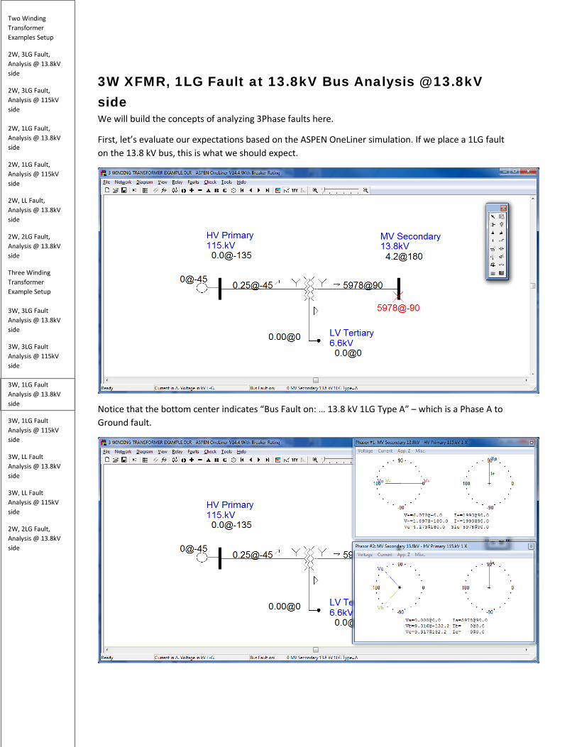
3W XFMR, 1LG Fault at 13.8kV Bus Analysis @ 13.8kV side We will build the concepts of analyzing 3Phase faults here.
First, let’s evaluate our expectations based on the ASPEN OneLiner simulation. If we place a 1LG fault on the 13.8 kV bus, this is what we should expect.
Notice that the bottom center indicates “Bus Fault on: … 13.8 kV 1LG Type A” – which is a Phase A to Ground fault.
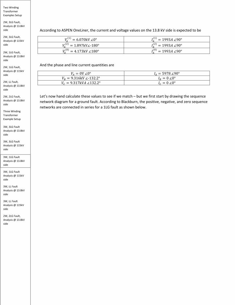
Two Winding Transformer Examples Setup
2W, 3LG Fault, Analysis @ 13.8kV side
2W, 3LG Fault, Analysis @ 115kV side 2W, 1LG Fault, Analysis @ 13.8kV side
2W, 1LG Fault, Analysis @ 115kV side
2W, LL Fault, Analysis @ 13.8kV side
2W, 2LG Fault, Analysis @ 13.8kV side
Three Winding Transformer Example Setup 3W, 3LG Fault Analysis @ 13.8kV side
3W, 3LG Fault Analysis @ 115kV side 3W, 1LG Fault Analysis @ 13.8kV side
3W, 1LG Fault Analysis @ 115kV side
3W, LL Fault Analysis @ 13.8kV side
3W, LL Fault Analysis @ 115kV side
2W, 2LG Fault, Analysis @ 13.8kV side
According to ASPEN OneLiner, the current and voltage values on the 13.8 kV side is expected to be
𝑘𝑘𝑀𝑀(1) = 6.070kV ∠0° 𝐼𝐼𝑀𝑀
(1) = 1993𝑀𝑀 ∠90° 𝑘𝑘𝑀𝑀
(2) = 1.897kV∠-180° 𝐼𝐼𝑀𝑀(2) = 1993𝑀𝑀 ∠90°
𝑘𝑘𝑀𝑀(0) = 4.173kV ∠180° 𝐼𝐼𝑀𝑀
(0) = 1993𝑀𝑀 ∠90°
And the phase and line current quantities are
𝑘𝑘𝑀𝑀 = 0V ∠0° 𝐼𝐼𝑀𝑀 = 5978 ∠90° 𝑘𝑘𝐵𝐵 = 9.316kV ∠-132.2° 𝐼𝐼𝐵𝐵 = 0 ∠0° 𝑘𝑘𝐶𝐶 = 9.317kV𝑀𝑀 ∠132.2° 𝐼𝐼𝐶𝐶 = 0 ∠0°
Let’s now hand calculate these values to see if we match – but we first start by drawing the sequence network diagram for a ground fault. According to Blackburn, the positive, negative, and zero sequence networks are connected in series for a 1LG fault as shown below.
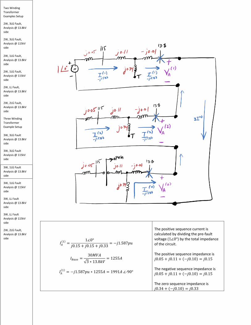
Two Winding Transformer Examples Setup
2W, 3LG Fault, Analysis @ 13.8kV side
2W, 3LG Fault, Analysis @ 115kV side 2W, 1LG Fault, Analysis @ 13.8kV side
2W, 1LG Fault, Analysis @ 115kV side
2W, LL Fault, Analysis @ 13.8kV side
2W, 2LG Fault, Analysis @ 13.8kV side
Three Winding Transformer Example Setup 3W, 3LG Fault Analysis @ 13.8kV side
3W, 3LG Fault Analysis @ 115kV side 3W, 1LG Fault Analysis @ 13.8kV side
3W, 1LG Fault Analysis @ 115kV side
3W, LL Fault Analysis @ 13.8kV side
3W, LL Fault Analysis @ 115kV side
2W, 2LG Fault, Analysis @ 13.8kV side
𝐼𝐼𝑀𝑀(1) =
1∠0°𝑗𝑗0.15 + 𝑗𝑗0.15 + 𝑗𝑗0.33
= −𝑗𝑗1.587𝑝𝑝𝑝𝑝
𝐼𝐼𝐵𝐵𝑏𝑏𝑠𝑠𝑏𝑏 =30𝑀𝑀𝑘𝑘𝑀𝑀
√3 ∗ 13.8𝑘𝑘𝑘𝑘= 1255𝑀𝑀
𝐼𝐼𝑀𝑀
(1) = −𝑗𝑗1.587𝑝𝑝𝑝𝑝 ∗ 1255𝑀𝑀 = 1991𝑀𝑀 ∠-90°
The positive sequence current is calculated by dividing the pre-fault voltage (1∠0°) by the total impedance of the circuit. The positive sequence impedance is 𝑗𝑗0.05 + 𝑗𝑗0.11 + (−𝑗𝑗0.10) = 𝑗𝑗0.15 The negative sequence impedance is 𝑗𝑗0.05 + 𝑗𝑗0.11 + (−𝑗𝑗0.10) = 𝑗𝑗0.15 The zero sequence impedance is 𝑗𝑗0.34 + (−𝑗𝑗0.10) = 𝑗𝑗0.33

Two Winding Transformer Examples Setup
2W, 3LG Fault, Analysis @ 13.8kV side
2W, 3LG Fault, Analysis @ 115kV side 2W, 1LG Fault, Analysis @ 13.8kV side
2W, 1LG Fault, Analysis @ 115kV side
2W, LL Fault, Analysis @ 13.8kV side
2W, 2LG Fault, Analysis @ 13.8kV side
Three Winding Transformer Example Setup 3W, 3LG Fault Analysis @ 13.8kV side
3W, 3LG Fault Analysis @ 115kV side 3W, 1LG Fault Analysis @ 13.8kV side
3W, 1LG Fault Analysis @ 115kV side
3W, LL Fault Analysis @ 13.8kV side
3W, LL Fault Analysis @ 115kV side
2W, 2LG Fault, Analysis @ 13.8kV side
The positive sequence current matches the result shown in ASPEN OneLiner with an exception of the 180 degrees difference in the angle.
𝐼𝐼𝑀𝑀(2) = −𝑗𝑗1.587𝑝𝑝𝑝𝑝
𝐼𝐼𝑀𝑀
(1) = −𝑗𝑗1.587𝑝𝑝𝑝𝑝 ∗ 𝐼𝐼𝐵𝐵𝑏𝑏𝑠𝑠𝑏𝑏 = 1991𝑀𝑀 ∠-90°
Since the same positive sequence current flows through both the negative sequence and zero sequence networks for a 1LG fault, 𝐼𝐼𝑀𝑀
(1) = 𝐼𝐼𝑀𝑀(2) = 𝐼𝐼𝑀𝑀
(0) This also agrees with Aspen Oneliner, with an exception of the angle.
𝐼𝐼𝑀𝑀
(0) = −𝑗𝑗1.587𝑝𝑝𝑝𝑝
𝐼𝐼𝑀𝑀(0) = −𝑗𝑗1.587𝑝𝑝𝑝𝑝 ∗ 𝐼𝐼𝐵𝐵𝑏𝑏𝑠𝑠𝑏𝑏 = 1991𝑀𝑀 ∠-90°
Let’s determine the phase current values for the 1LG fault on the 13.8 kV side.
𝐼𝐼𝑀𝑀 = 𝐼𝐼𝑀𝑀
(1) + 𝐼𝐼𝑀𝑀(2) + 𝐼𝐼𝑀𝑀
(0)
= (-𝑗𝑗1.587𝑝𝑝𝑝𝑝) + (-𝑗𝑗1.587𝑝𝑝𝑝𝑝)+ (-𝑗𝑗1.587𝑝𝑝𝑝𝑝)
𝐼𝐼𝑀𝑀 = -𝑗𝑗4.762 𝑝𝑝𝑝𝑝
𝐼𝐼𝐵𝐵𝑏𝑏𝑠𝑠𝑏𝑏 =30𝑀𝑀𝑘𝑘𝑀𝑀
√3 ∗ 13.8𝑘𝑘𝑘𝑘= 1255.109𝑀𝑀
-𝑗𝑗4.762 ∗ 𝐼𝐼𝐵𝐵𝑏𝑏𝑠𝑠𝑏𝑏 = 5978𝑀𝑀 ∠-90°
Another way of representing phase A current is
3𝐼𝐼𝑀𝑀(0) = -𝑗𝑗4.762 𝑝𝑝𝑝𝑝 → 5978𝑀𝑀 ∠-90°
Using the principles of symmetrical components, we know that phase A current is the sum of positive, negative, and zero sequence currents. This result matches the ASPEN OneLiner simulation with an exception of the phase angle which is 180 degrees apart.

Two Winding Transformer Examples Setup
2W, 3LG Fault, Analysis @ 13.8kV side
2W, 3LG Fault, Analysis @ 115kV side 2W, 1LG Fault, Analysis @ 13.8kV side
2W, 1LG Fault, Analysis @ 115kV side
2W, LL Fault, Analysis @ 13.8kV side
2W, 2LG Fault, Analysis @ 13.8kV side
Three Winding Transformer Example Setup 3W, 3LG Fault Analysis @ 13.8kV side
3W, 3LG Fault Analysis @ 115kV side 3W, 1LG Fault Analysis @ 13.8kV side
3W, 1LG Fault Analysis @ 115kV side
3W, LL Fault Analysis @ 13.8kV side
3W, LL Fault Analysis @ 115kV side
2W, 2LG Fault, Analysis @ 13.8kV side
𝐼𝐼𝐵𝐵 = 𝑅𝑅2 ∗ 𝐼𝐼𝑀𝑀(1) + 𝑅𝑅 ∗ 𝐼𝐼𝑀𝑀
(2) + 𝐼𝐼𝑀𝑀(0)
𝐼𝐼𝐵𝐵 = (1∠240°)(−j1.587) + (1∠120°)(−j1.587) + (−j1.587)
𝐼𝐼𝐵𝐵 = 0
To calculate phase B current, we must shift the positive sequence current by 240 degrees CCW and negative sequence current by 120 degrees CCW per fundamentals of symmetrical components. The total fault current on phase B equals 0 – this result makes sense because the fault is on phase A and B, so phase B should have no fault current. This result matches the ASPEN OneLiner simulation.
𝐼𝐼𝐶𝐶 = 𝑅𝑅 ∗ 𝐼𝐼𝑀𝑀(1) + 𝑅𝑅2 ∗ 𝐼𝐼𝑀𝑀
(2) + 𝐼𝐼𝑀𝑀(0)
𝐼𝐼𝐶𝐶 = (1∠120°)(−j1.587) + (1∠240°)(−j1.587) + (−j1.587)
= 0
𝐼𝐼𝐶𝐶 = 0
Let’s determine the sequence voltages for the 1LG fault on the 13.8kV side.
𝑘𝑘𝑀𝑀(1) = 1 ∠0° − (j0.15)(−j1.587) = +0.76195 pu
𝑘𝑘𝐵𝐵𝑏𝑏𝑠𝑠𝑏𝑏 =13.8kV√3
(0.76195 ) ∗ 𝑘𝑘𝐵𝐵𝑏𝑏𝑠𝑠𝑏𝑏 = 6.07kV∠0°
If we perform KVL around the positive sequence network and calculate the voltage at the point of the fault, we will always find it equal to the pre-fault voltage minus the positive sequence impedance times the positive sequence current. Notice that this is a positive voltage value so the angle is at 0 degrees. This is the same value as the Aspen Oneliner simulation

Two Winding Transformer Examples Setup
2W, 3LG Fault, Analysis @ 13.8kV side
2W, 3LG Fault, Analysis @ 115kV side 2W, 1LG Fault, Analysis @ 13.8kV side
2W, 1LG Fault, Analysis @ 115kV side
2W, LL Fault, Analysis @ 13.8kV side
2W, 2LG Fault, Analysis @ 13.8kV side
Three Winding Transformer Example Setup 3W, 3LG Fault Analysis @ 13.8kV side
3W, 3LG Fault Analysis @ 115kV side 3W, 1LG Fault Analysis @ 13.8kV side
3W, 1LG Fault Analysis @ 115kV side
3W, LL Fault Analysis @ 13.8kV side
3W, LL Fault Analysis @ 115kV side
2W, 2LG Fault, Analysis @ 13.8kV side
𝑘𝑘𝑀𝑀(2) = 0 − (j0.15)(−j1.587) = −0.23805
𝑘𝑘𝑀𝑀(2) = (−0.23805) ∗ �
13.8𝑘𝑘𝑘𝑘√3
� = 1.897kV∠180°
Similarly, performing KVL around the negative sequence network always gives us zero minus the negative sequence impedance multiplied by the negative sequence current. Note the negative sign, the negative sign indicates the negative sequence voltage is 180 degrees out of phase compared to the positive sequence voltage. This is the same value as the ASPEN OneLiner simulation
𝑘𝑘𝑀𝑀(0) = 0 − (j0.33)(−j1.587) = −0.5237
𝑘𝑘𝑀𝑀(0) = (−0.5237) ∗ �
13.8𝑘𝑘𝑘𝑘√3
� = 4.172kV∠180°
Similarly, performing KVL around the Zero sequence network results in the following – using the same concept as discussed previously. Note that negative sign… this indicates the Zero sequence voltage is 180 degrees out of phase compared to the positive sequence voltage and in phase compared to the negative sequence voltage. This is the same value as the Aspen Oneliner simulation
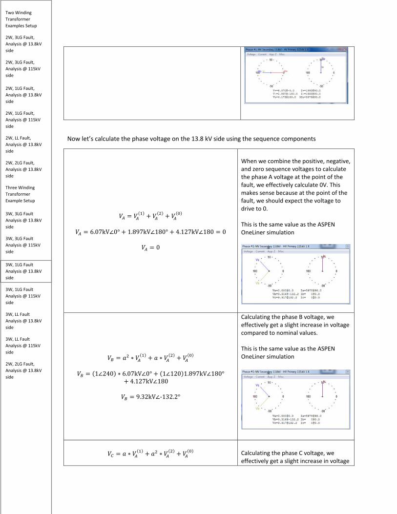
Two Winding Transformer Examples Setup
2W, 3LG Fault, Analysis @ 13.8kV side
2W, 3LG Fault, Analysis @ 115kV side 2W, 1LG Fault, Analysis @ 13.8kV side
2W, 1LG Fault, Analysis @ 115kV side
2W, LL Fault, Analysis @ 13.8kV side
2W, 2LG Fault, Analysis @ 13.8kV side
Three Winding Transformer Example Setup 3W, 3LG Fault Analysis @ 13.8kV side
3W, 3LG Fault Analysis @ 115kV side 3W, 1LG Fault Analysis @ 13.8kV side
3W, 1LG Fault Analysis @ 115kV side
3W, LL Fault Analysis @ 13.8kV side
3W, LL Fault Analysis @ 115kV side
2W, 2LG Fault, Analysis @ 13.8kV side
Now let’s calculate the phase voltage on the 13.8 kV side using the sequence components
𝑘𝑘𝑀𝑀 = 𝑘𝑘𝑀𝑀(1) + 𝑘𝑘𝑀𝑀
(2) + 𝑘𝑘𝑀𝑀(0)
𝑘𝑘𝑀𝑀 = 6.07kV∠0° + 1.897kV∠180° + 4.127kV∠180 = 0
𝑘𝑘𝑀𝑀 = 0
When we combine the positive, negative, and zero sequence voltages to calculate the phase A voltage at the point of the fault, we effectively calculate 0V. This makes sense because at the point of the fault, we should expect the voltage to drive to 0. This is the same value as the ASPEN OneLiner simulation
𝑘𝑘𝐵𝐵 = 𝑅𝑅2 ∗ 𝑘𝑘𝑀𝑀
(1) + 𝑅𝑅 ∗ 𝑘𝑘𝑀𝑀(2) + 𝑘𝑘𝑀𝑀
(0)
𝑘𝑘𝐵𝐵 = (1∠240) ∗ 6.07kV∠0° + (1∠120)1.897kV∠180°+ 4.127kV∠180
𝑘𝑘𝐵𝐵 = 9.32kV∠-132.2°
Calculating the phase B voltage, we effectively get a slight increase in voltage compared to nominal values. This is the same value as the ASPEN OneLiner simulation
𝑘𝑘𝐶𝐶 = 𝑅𝑅 ∗ 𝑘𝑘𝑀𝑀
(1) + 𝑅𝑅2 ∗ 𝑘𝑘𝑀𝑀(2) + 𝑘𝑘𝑀𝑀
(0)
Calculating the phase C voltage, we effectively get a slight increase in voltage
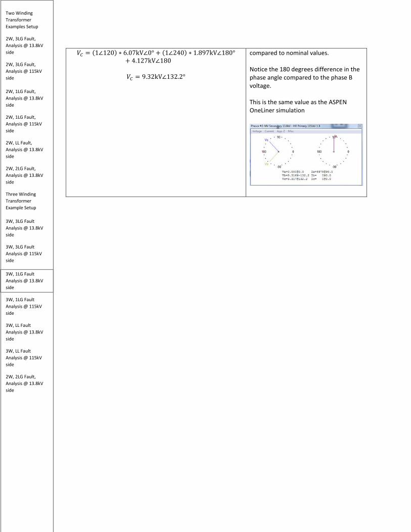
Two Winding Transformer Examples Setup
2W, 3LG Fault, Analysis @ 13.8kV side
2W, 3LG Fault, Analysis @ 115kV side 2W, 1LG Fault, Analysis @ 13.8kV side
2W, 1LG Fault, Analysis @ 115kV side
2W, LL Fault, Analysis @ 13.8kV side
2W, 2LG Fault, Analysis @ 13.8kV side
Three Winding Transformer Example Setup 3W, 3LG Fault Analysis @ 13.8kV side
3W, 3LG Fault Analysis @ 115kV side 3W, 1LG Fault Analysis @ 13.8kV side
3W, 1LG Fault Analysis @ 115kV side
3W, LL Fault Analysis @ 13.8kV side
3W, LL Fault Analysis @ 115kV side
2W, 2LG Fault, Analysis @ 13.8kV side
𝑘𝑘𝐶𝐶 = (1∠120) ∗ 6.07kV∠0° + (1∠240) ∗ 1.897kV∠180°+ 4.127kV∠180
𝑘𝑘𝐶𝐶 = 9.32kV∠132.2°
compared to nominal values. Notice the 180 degrees difference in the phase angle compared to the phase B voltage. This is the same value as the ASPEN OneLiner simulation
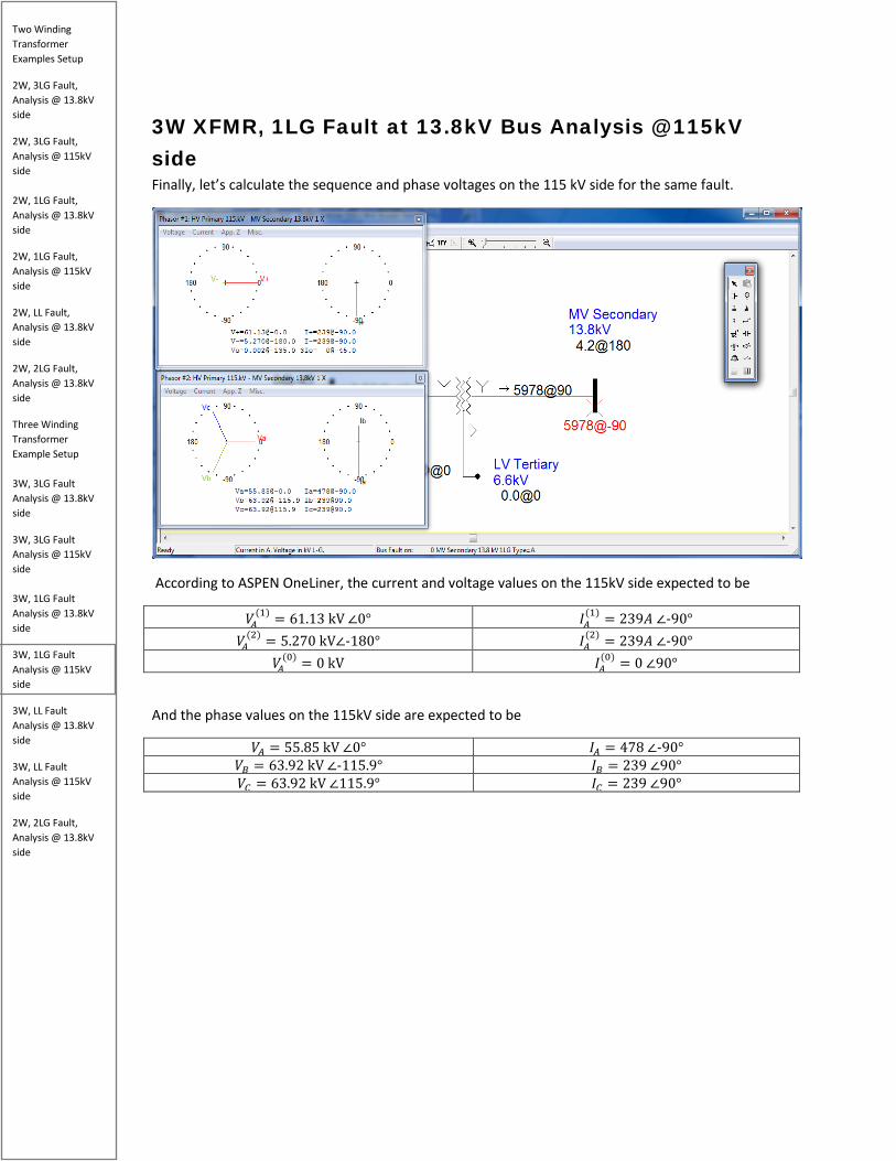
Two Winding Transformer Examples Setup
2W, 3LG Fault, Analysis @ 13.8kV side
2W, 3LG Fault, Analysis @ 115kV side 2W, 1LG Fault, Analysis @ 13.8kV side
2W, 1LG Fault, Analysis @ 115kV side
2W, LL Fault, Analysis @ 13.8kV side
2W, 2LG Fault, Analysis @ 13.8kV side
Three Winding Transformer Example Setup 3W, 3LG Fault Analysis @ 13.8kV side
3W, 3LG Fault Analysis @ 115kV side 3W, 1LG Fault Analysis @ 13.8kV side
3W, 1LG Fault Analysis @ 115kV side
3W, LL Fault Analysis @ 13.8kV side
3W, LL Fault Analysis @ 115kV side
2W, 2LG Fault, Analysis @ 13.8kV side
3W XFMR, 1LG Fault at 13.8kV Bus Analysis @ 115kV side Finally, let’s calculate the sequence and phase voltages on the 115 kV side for the same fault.
According to ASPEN OneLiner, the current and voltage values on the 115kV side expected to be
𝑘𝑘𝑀𝑀(1) = 61.13 kV ∠0° 𝐼𝐼𝑀𝑀
(1) = 239𝑀𝑀 ∠-90° 𝑘𝑘𝑀𝑀
(2) = 5.270 kV∠-180° 𝐼𝐼𝑀𝑀(2) = 239𝑀𝑀 ∠-90°
𝑘𝑘𝑀𝑀(0) = 0 kV 𝐼𝐼𝑀𝑀
(0) = 0 ∠90°
And the phase values on the 115kV side are expected to be
𝑘𝑘𝑀𝑀 = 55.85 kV ∠0° 𝐼𝐼𝑀𝑀 = 478 ∠-90° 𝑘𝑘𝐵𝐵 = 63.92 kV ∠-115.9° 𝐼𝐼𝐵𝐵 = 239 ∠90° 𝑘𝑘𝐶𝐶 = 63.92 kV ∠115.9° 𝐼𝐼𝐶𝐶 = 239 ∠90°

Two Winding Transformer Examples Setup
2W, 3LG Fault, Analysis @ 13.8kV side
2W, 3LG Fault, Analysis @ 115kV side 2W, 1LG Fault, Analysis @ 13.8kV side
2W, 1LG Fault, Analysis @ 115kV side
2W, LL Fault, Analysis @ 13.8kV side
2W, 2LG Fault, Analysis @ 13.8kV side
Three Winding Transformer Example Setup 3W, 3LG Fault Analysis @ 13.8kV side
3W, 3LG Fault Analysis @ 115kV side 3W, 1LG Fault Analysis @ 13.8kV side
3W, 1LG Fault Analysis @ 115kV side
3W, LL Fault Analysis @ 13.8kV side
3W, LL Fault Analysis @ 115kV side
2W, 2LG Fault, Analysis @ 13.8kV side
Now let’s hand-calculate the phase currents on the 115 kV side
𝐼𝐼𝑀𝑀
(1) = −𝑗𝑗1.587𝑝𝑝𝑝𝑝
𝐼𝐼𝐵𝐵𝑏𝑏𝑠𝑠𝑏𝑏 =30𝑀𝑀𝑘𝑘𝑀𝑀
√3 ∗ 115𝑘𝑘𝑘𝑘= 150.613𝑀𝑀
𝐼𝐼𝑀𝑀
(1) = −𝑗𝑗1.587𝑝𝑝𝑝𝑝 ∗ 𝐼𝐼𝐵𝐵𝑏𝑏𝑠𝑠𝑏𝑏 = 239A ∠-90°
The positive sequence current that flows through the 13.8kV side is the same as the 115kV side. The only difference is the base. This matches the ASPEN OneLiner result.
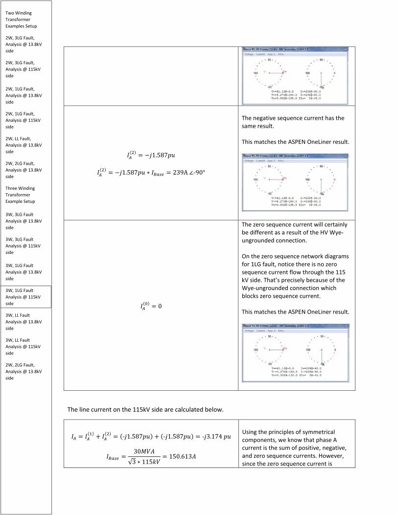
Two Winding Transformer Examples Setup
2W, 3LG Fault, Analysis @ 13.8kV side
2W, 3LG Fault, Analysis @ 115kV side 2W, 1LG Fault, Analysis @ 13.8kV side
2W, 1LG Fault, Analysis @ 115kV side
2W, LL Fault, Analysis @ 13.8kV side
2W, 2LG Fault, Analysis @ 13.8kV side
Three Winding Transformer Example Setup 3W, 3LG Fault Analysis @ 13.8kV side
3W, 3LG Fault Analysis @ 115kV side 3W, 1LG Fault Analysis @ 13.8kV side
3W, 1LG Fault Analysis @ 115kV side
3W, LL Fault Analysis @ 13.8kV side
3W, LL Fault Analysis @ 115kV side
2W, 2LG Fault, Analysis @ 13.8kV side
𝐼𝐼𝑀𝑀
(2) = −𝑗𝑗1.587𝑝𝑝𝑝𝑝
𝐼𝐼𝑀𝑀(2) = −𝑗𝑗1.587𝑝𝑝𝑝𝑝 ∗ 𝐼𝐼𝐵𝐵𝑏𝑏𝑠𝑠𝑏𝑏 = 239A ∠-90°
The negative sequence current has the same result. This matches the ASPEN OneLiner result.
𝐼𝐼𝑀𝑀(0) = 0
The zero sequence current will certainly be different as a result of the HV Wye-ungrounded connection. On the zero sequence network diagrams for 1LG fault, notice there is no zero sequence current flow through the 115 kV side. That’s precisely because of the Wye-ungrounded connection which blocks zero sequence current. This matches the ASPEN OneLiner result.
The line current on the 115kV side are calculated below.
𝐼𝐼𝑀𝑀 = 𝐼𝐼𝑀𝑀
(1) + 𝐼𝐼𝑀𝑀(2) = (-𝑗𝑗1.587𝑝𝑝𝑝𝑝) + (-𝑗𝑗1.587𝑝𝑝𝑝𝑝) = -𝑗𝑗3.174 𝑝𝑝𝑝𝑝
𝐼𝐼𝐵𝐵𝑏𝑏𝑠𝑠𝑏𝑏 =30𝑀𝑀𝑘𝑘𝑀𝑀
√3 ∗ 115𝑘𝑘𝑘𝑘= 150.613𝑀𝑀
Using the principles of symmetrical components, we know that phase A current is the sum of positive, negative, and zero sequence currents. However, since the zero sequence current is

Two Winding Transformer Examples Setup
2W, 3LG Fault, Analysis @ 13.8kV side
2W, 3LG Fault, Analysis @ 115kV side 2W, 1LG Fault, Analysis @ 13.8kV side
2W, 1LG Fault, Analysis @ 115kV side
2W, LL Fault, Analysis @ 13.8kV side
2W, 2LG Fault, Analysis @ 13.8kV side
Three Winding Transformer Example Setup 3W, 3LG Fault Analysis @ 13.8kV side
3W, 3LG Fault Analysis @ 115kV side 3W, 1LG Fault Analysis @ 13.8kV side
3W, 1LG Fault Analysis @ 115kV side
3W, LL Fault Analysis @ 13.8kV side
3W, LL Fault Analysis @ 115kV side
2W, 2LG Fault, Analysis @ 13.8kV side
𝐼𝐼𝑀𝑀 = -𝑗𝑗3.174 ∗ 𝐼𝐼𝐵𝐵𝑏𝑏𝑠𝑠𝑏𝑏 = 478 ∠-90°
blocked, we omit the zero sequence current from our calculations. This matches the ASPEN OneLiner result.
𝐼𝐼𝐵𝐵 = 𝑅𝑅2 ∗ 𝐼𝐼𝑀𝑀
(1) + 𝑅𝑅 ∗ 𝐼𝐼𝑀𝑀(2) + 𝐼𝐼𝑀𝑀
(0)
𝐼𝐼𝐵𝐵 = (1∠240°)(−j1.587) + (1∠120°)(−j1.587)= +𝑗𝑗1.587𝑝𝑝𝑝𝑝
𝐼𝐼𝐵𝐵 = +𝑗𝑗1.587𝑝𝑝𝑝𝑝 ∗ 𝐼𝐼𝐵𝐵𝑏𝑏𝑠𝑠𝑏𝑏 = 239.02𝑀𝑀 ∠90°
To calculate Phase B current, we must shift the positive sequence current by 240 degrees CCW and negative sequence current by 120 degrees CCW per fundamentals of symmetrical components. Again, we omit the zero sequence current because it does not flow through the 115kV side. This result matches the ASPEN OneLiner simulation.
𝐼𝐼𝐶𝐶 = 𝑅𝑅 ∗ 𝐼𝐼𝑀𝑀(1) + 𝑅𝑅2 ∗ 𝐼𝐼𝑀𝑀
(2)
𝐼𝐼𝐶𝐶 = (1∠120°)(−j1.587) + (1∠240°)(−j1.587)= +𝑗𝑗1.587𝑝𝑝𝑝𝑝
𝐼𝐼𝐶𝐶 = +𝑗𝑗1.587𝑝𝑝𝑝𝑝 ∗ 𝐼𝐼𝐵𝐵𝑏𝑏𝑠𝑠𝑏𝑏 = 239.02𝑀𝑀 ∠90°
Now let’s calculate the sequence voltage on the 115kV side.
𝑘𝑘𝑀𝑀(1) = 1 ∠0° − (𝑗𝑗0.05)(−j1.587) = 0.92065 pu
𝑘𝑘𝐵𝐵𝑏𝑏𝑠𝑠𝑏𝑏 =115kV√3
𝑘𝑘𝑀𝑀
(1) = (0.92065 ) ∗ 𝑘𝑘𝐵𝐵𝑏𝑏𝑠𝑠𝑏𝑏 = 61.13kV∠0°
If we perform KVL around the positive sequence network and calculate the voltage at the point of the fault, we will always find it equal to the pre-fault voltage minus the positive sequence impedance times the positive sequence current. Since, we want to know the positive sequence current only on the 115kV side, we need to select the

Two Winding Transformer Examples Setup
2W, 3LG Fault, Analysis @ 13.8kV side
2W, 3LG Fault, Analysis @ 115kV side 2W, 1LG Fault, Analysis @ 13.8kV side
2W, 1LG Fault, Analysis @ 115kV side
2W, LL Fault, Analysis @ 13.8kV side
2W, 2LG Fault, Analysis @ 13.8kV side
Three Winding Transformer Example Setup 3W, 3LG Fault Analysis @ 13.8kV side
3W, 3LG Fault Analysis @ 115kV side 3W, 1LG Fault Analysis @ 13.8kV side
3W, 1LG Fault Analysis @ 115kV side
3W, LL Fault Analysis @ 13.8kV side
3W, LL Fault Analysis @ 115kV side
2W, 2LG Fault, Analysis @ 13.8kV side
appropriate positive sequence impedance, which is 𝑗𝑗0.05 This is the same value as the ASPEN OneLiner simulation
𝑘𝑘𝑀𝑀(2) = 0 − (j0.05)(−j1.587) = −0.07935
𝑘𝑘𝑀𝑀
(2) = (−0.07935) ∗ 𝑘𝑘𝑏𝑏𝑏𝑏𝑠𝑠𝑏𝑏 = 5.27 kV∠180°
Similarly, performing KVL around the negative sequence network always gives us zero minus the negative sequence impedance multiplied by the negative sequence current. We just need to select the appropriate impedance this time since we want the negative sequence voltage. Note that the negative sign indicates the negative sequence voltage is 180 degrees out of phase compared to the positive sequence voltage. This is the same value as the ASPEN OneLiner simulation
𝑘𝑘𝑀𝑀(0) = 0
The zero sequence voltage will be zero since the Wye-ungrounded connection blocks the zero sequence current on the HV side. This is the same value as the ASPEN OneLiner simulation
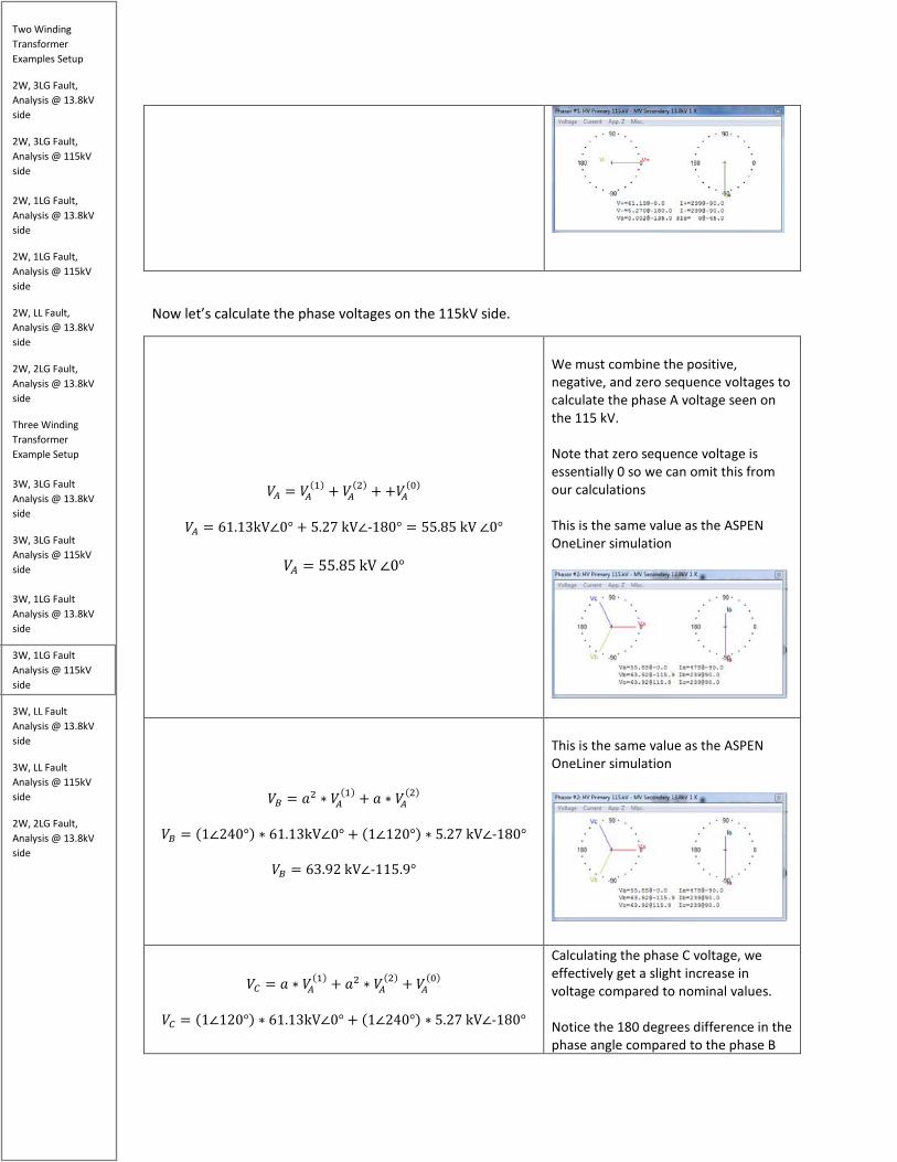
Two Winding Transformer Examples Setup
2W, 3LG Fault, Analysis @ 13.8kV side
2W, 3LG Fault, Analysis @ 115kV side 2W, 1LG Fault, Analysis @ 13.8kV side
2W, 1LG Fault, Analysis @ 115kV side
2W, LL Fault, Analysis @ 13.8kV side
2W, 2LG Fault, Analysis @ 13.8kV side
Three Winding Transformer Example Setup 3W, 3LG Fault Analysis @ 13.8kV side
3W, 3LG Fault Analysis @ 115kV side 3W, 1LG Fault Analysis @ 13.8kV side
3W, 1LG Fault Analysis @ 115kV side
3W, LL Fault Analysis @ 13.8kV side
3W, LL Fault Analysis @ 115kV side
2W, 2LG Fault, Analysis @ 13.8kV side
Now let’s calculate the phase voltages on the 115kV side.
𝑘𝑘𝑀𝑀 = 𝑘𝑘𝑀𝑀(1) + 𝑘𝑘𝑀𝑀
(2) + +𝑘𝑘𝑀𝑀(0)
𝑘𝑘𝑀𝑀 = 61.13kV∠0° + 5.27 kV∠-180° = 55.85 kV ∠0°
𝑘𝑘𝑀𝑀 = 55.85 kV ∠0°
We must combine the positive, negative, and zero sequence voltages to calculate the phase A voltage seen on the 115 kV. Note that zero sequence voltage is essentially 0 so we can omit this from our calculations This is the same value as the ASPEN OneLiner simulation
𝑘𝑘𝐵𝐵 = 𝑅𝑅2 ∗ 𝑘𝑘𝑀𝑀
(1) + 𝑅𝑅 ∗ 𝑘𝑘𝑀𝑀(2)
𝑘𝑘𝐵𝐵 = (1∠240°) ∗ 61.13kV∠0° + (1∠120°) ∗ 5.27 kV∠-180°
𝑘𝑘𝐵𝐵 = 63.92 kV∠-115.9°
This is the same value as the ASPEN OneLiner simulation
𝑘𝑘𝐶𝐶 = 𝑅𝑅 ∗ 𝑘𝑘𝑀𝑀
(1) + 𝑅𝑅2 ∗ 𝑘𝑘𝑀𝑀(2) + 𝑘𝑘𝑀𝑀
(0) 𝑘𝑘𝐶𝐶 = (1∠120°) ∗ 61.13kV∠0° + (1∠240°) ∗ 5.27 kV∠-180°
Calculating the phase C voltage, we effectively get a slight increase in voltage compared to nominal values. Notice the 180 degrees difference in the phase angle compared to the phase B

Two Winding Transformer Examples Setup
2W, 3LG Fault, Analysis @ 13.8kV side
2W, 3LG Fault, Analysis @ 115kV side 2W, 1LG Fault, Analysis @ 13.8kV side
2W, 1LG Fault, Analysis @ 115kV side
2W, LL Fault, Analysis @ 13.8kV side
2W, 2LG Fault, Analysis @ 13.8kV side
Three Winding Transformer Example Setup 3W, 3LG Fault Analysis @ 13.8kV side
3W, 3LG Fault Analysis @ 115kV side 3W, 1LG Fault Analysis @ 13.8kV side
3W, 1LG Fault Analysis @ 115kV side
3W, LL Fault Analysis @ 13.8kV side
3W, LL Fault Analysis @ 115kV side
2W, 2LG Fault, Analysis @ 13.8kV side
𝑘𝑘𝐶𝐶 = 63.92 kV∠115.9°
voltage. This is the same value as the ASPEN OneLiner simulation
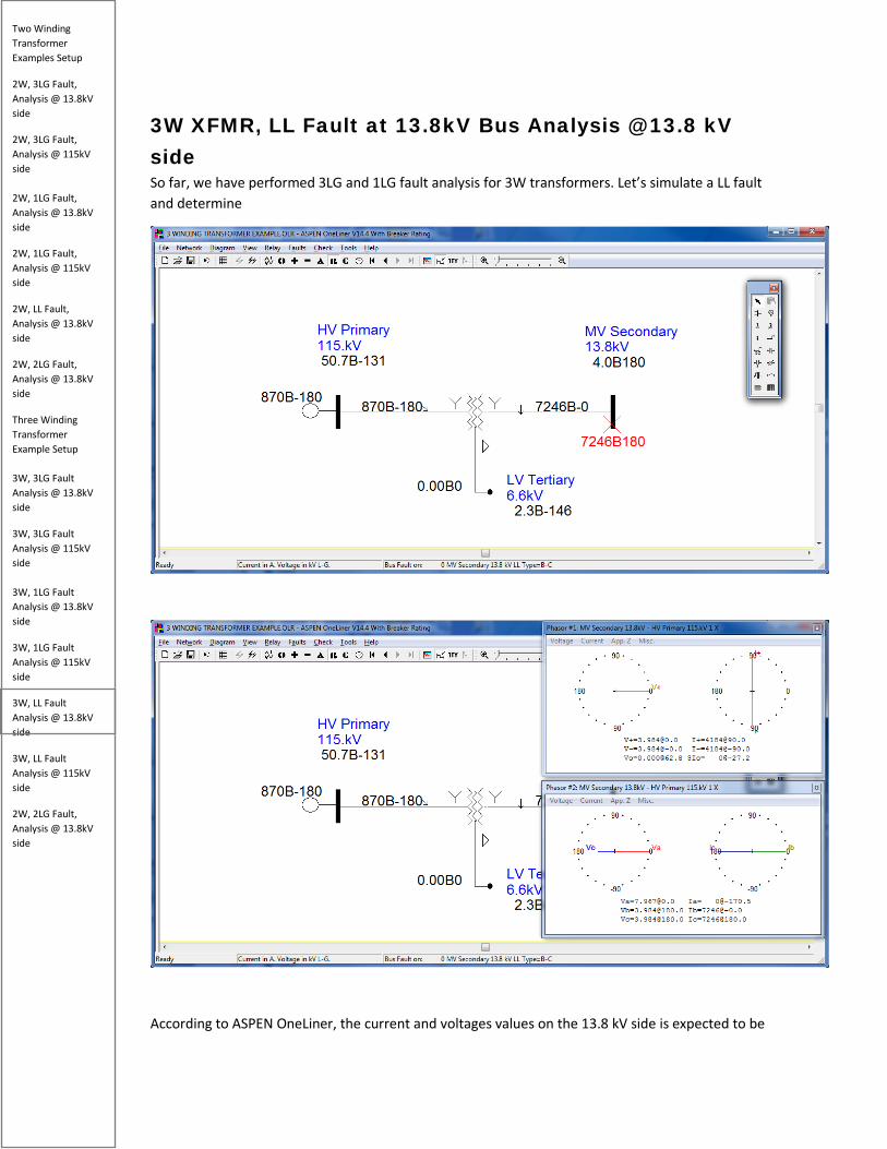
Two Winding Transformer Examples Setup
2W, 3LG Fault, Analysis @ 13.8kV side
2W, 3LG Fault, Analysis @ 115kV side 2W, 1LG Fault, Analysis @ 13.8kV side
2W, 1LG Fault, Analysis @ 115kV side
2W, LL Fault, Analysis @ 13.8kV side
2W, 2LG Fault, Analysis @ 13.8kV side
Three Winding Transformer Example Setup 3W, 3LG Fault Analysis @ 13.8kV side
3W, 3LG Fault Analysis @ 115kV side 3W, 1LG Fault Analysis @ 13.8kV side
3W, 1LG Fault Analysis @ 115kV side
3W, LL Fault Analysis @ 13.8kV side
3W, LL Fault Analysis @ 115kV side
2W, 2LG Fault, Analysis @ 13.8kV side
3W XFMR, LL Fault at 13.8kV Bus Analysis @ 13.8 kV side So far, we have performed 3LG and 1LG fault analysis for 3W transformers. Let’s simulate a LL fault and determine
According to ASPEN OneLiner, the current and voltages values on the 13.8 kV side is expected to be
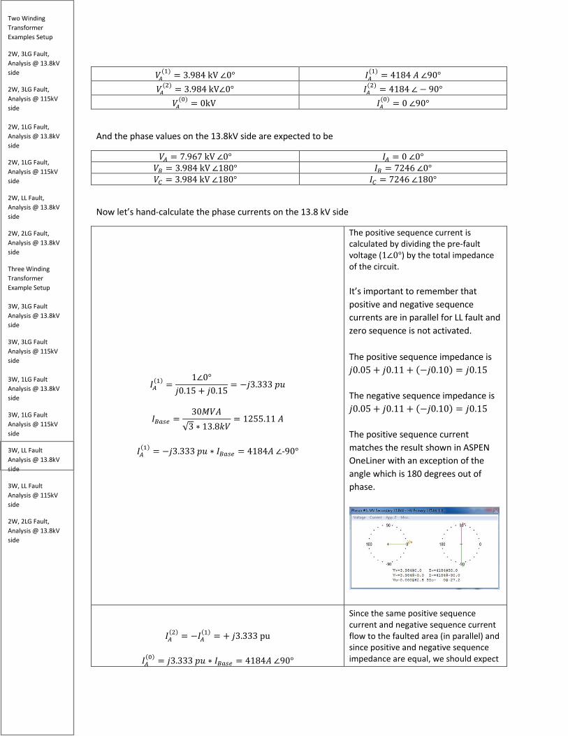
Two Winding Transformer Examples Setup
2W, 3LG Fault, Analysis @ 13.8kV side
2W, 3LG Fault, Analysis @ 115kV side 2W, 1LG Fault, Analysis @ 13.8kV side
2W, 1LG Fault, Analysis @ 115kV side
2W, LL Fault, Analysis @ 13.8kV side
2W, 2LG Fault, Analysis @ 13.8kV side
Three Winding Transformer Example Setup 3W, 3LG Fault Analysis @ 13.8kV side
3W, 3LG Fault Analysis @ 115kV side 3W, 1LG Fault Analysis @ 13.8kV side
3W, 1LG Fault Analysis @ 115kV side
3W, LL Fault Analysis @ 13.8kV side
3W, LL Fault Analysis @ 115kV side
2W, 2LG Fault, Analysis @ 13.8kV side
𝑘𝑘𝑀𝑀(1) = 3.984 kV ∠0° 𝐼𝐼𝑀𝑀
(1) = 4184 𝑀𝑀 ∠90° 𝑘𝑘𝑀𝑀
(2) = 3.984 kV∠0° 𝐼𝐼𝑀𝑀(2) = 4184 ∠ − 90°
𝑘𝑘𝑀𝑀(0) = 0kV 𝐼𝐼𝑀𝑀
(0) = 0 ∠90°
And the phase values on the 13.8kV side are expected to be
𝑘𝑘𝑀𝑀 = 7.967 kV ∠0° 𝐼𝐼𝑀𝑀 = 0 ∠0° 𝑘𝑘𝐵𝐵 = 3.984 kV ∠180° 𝐼𝐼𝐵𝐵 = 7246 ∠0° 𝑘𝑘𝐶𝐶 = 3.984 kV ∠180° 𝐼𝐼𝐶𝐶 = 7246 ∠180°
Now let’s hand-calculate the phase currents on the 13.8 kV side
𝐼𝐼𝑀𝑀(1) =
1∠0°𝑗𝑗0.15 + 𝑗𝑗0.15
= −𝑗𝑗3.333 𝑝𝑝𝑝𝑝
𝐼𝐼𝐵𝐵𝑏𝑏𝑠𝑠𝑏𝑏 =30𝑀𝑀𝑘𝑘𝑀𝑀
√3 ∗ 13.8𝑘𝑘𝑘𝑘= 1255.11 𝑀𝑀
𝐼𝐼𝑀𝑀
(1) = −𝑗𝑗3.333 𝑝𝑝𝑝𝑝 ∗ 𝐼𝐼𝐵𝐵𝑏𝑏𝑠𝑠𝑏𝑏 = 4184𝑀𝑀 ∠-90°
The positive sequence current is calculated by dividing the pre-fault voltage (1∠0°) by the total impedance of the circuit. It’s important to remember that positive and negative sequence currents are in parallel for LL fault and zero sequence is not activated. The positive sequence impedance is 𝑗𝑗0.05 + 𝑗𝑗0.11 + (−𝑗𝑗0.10) = 𝑗𝑗0.15 The negative sequence impedance is 𝑗𝑗0.05 + 𝑗𝑗0.11 + (−𝑗𝑗0.10) = 𝑗𝑗0.15 The positive sequence current matches the result shown in ASPEN OneLiner with an exception of the angle which is 180 degrees out of phase.
𝐼𝐼𝑀𝑀(2) = −𝐼𝐼𝑀𝑀
(1) = + 𝑗𝑗3.333 pu
𝐼𝐼𝑀𝑀(0) = 𝑗𝑗3.333 𝑝𝑝𝑝𝑝 ∗ 𝐼𝐼𝐵𝐵𝑏𝑏𝑠𝑠𝑏𝑏 = 4184𝑀𝑀 ∠90°
Since the same positive sequence current and negative sequence current flow to the faulted area (in parallel) and since positive and negative sequence impedance are equal, we should expect
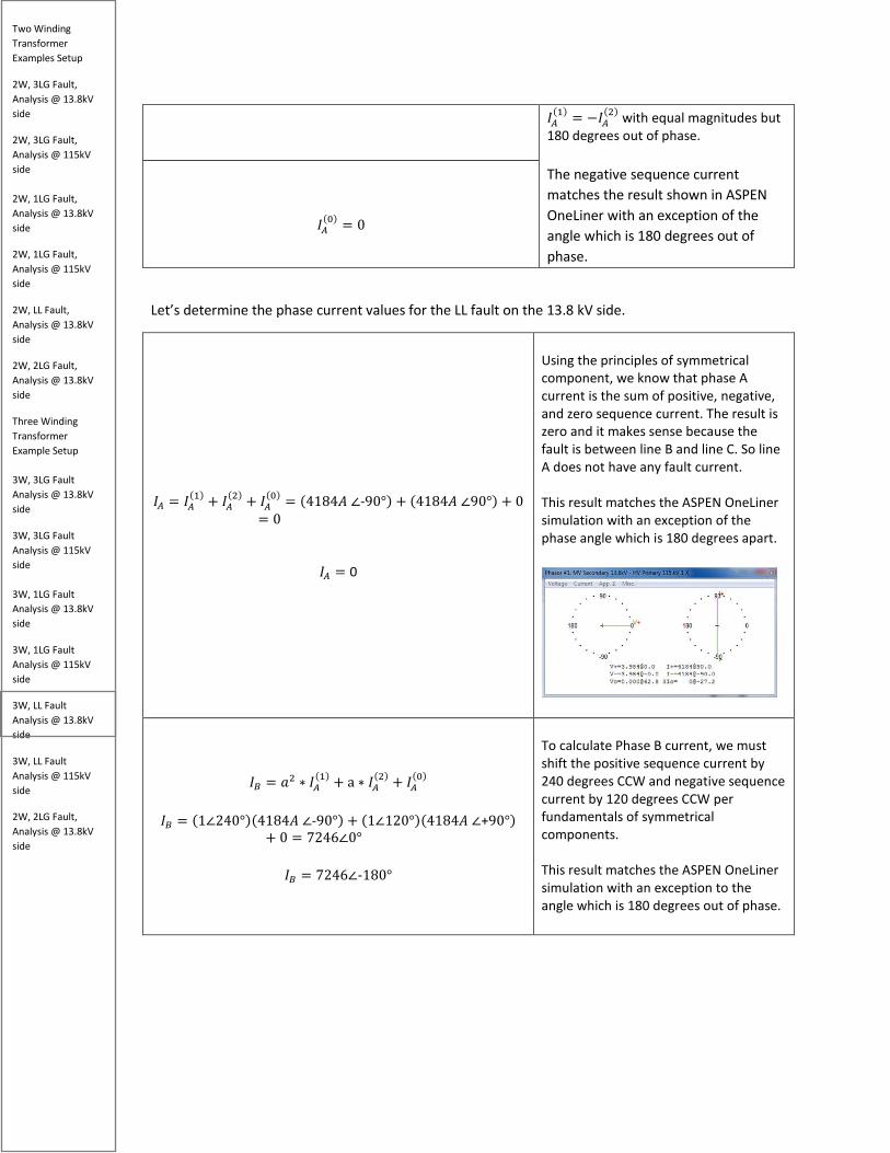
Two Winding Transformer Examples Setup
2W, 3LG Fault, Analysis @ 13.8kV side
2W, 3LG Fault, Analysis @ 115kV side 2W, 1LG Fault, Analysis @ 13.8kV side
2W, 1LG Fault, Analysis @ 115kV side
2W, LL Fault, Analysis @ 13.8kV side
2W, 2LG Fault, Analysis @ 13.8kV side
Three Winding Transformer Example Setup 3W, 3LG Fault Analysis @ 13.8kV side
3W, 3LG Fault Analysis @ 115kV side 3W, 1LG Fault Analysis @ 13.8kV side
3W, 1LG Fault Analysis @ 115kV side
3W, LL Fault Analysis @ 13.8kV side
3W, LL Fault Analysis @ 115kV side
2W, 2LG Fault, Analysis @ 13.8kV side
𝐼𝐼𝑀𝑀(1) = −𝐼𝐼𝑀𝑀
(2) with equal magnitudes but 180 degrees out of phase. The negative sequence current matches the result shown in ASPEN OneLiner with an exception of the angle which is 180 degrees out of phase.
𝐼𝐼𝑀𝑀
(0) = 0
Let’s determine the phase current values for the LL fault on the 13.8 kV side.
𝐼𝐼𝑀𝑀 = 𝐼𝐼𝑀𝑀
(1) + 𝐼𝐼𝑀𝑀(2) + 𝐼𝐼𝑀𝑀
(0) = (4184𝑀𝑀 ∠-90°) + (4184𝑀𝑀 ∠90°) + 0= 0
𝐼𝐼𝑀𝑀 = 0
Using the principles of symmetrical component, we know that phase A current is the sum of positive, negative, and zero sequence current. The result is zero and it makes sense because the fault is between line B and line C. So line A does not have any fault current. This result matches the ASPEN OneLiner simulation with an exception of the phase angle which is 180 degrees apart.
𝐼𝐼𝐵𝐵 = 𝑅𝑅2 ∗ 𝐼𝐼𝑀𝑀(1) + a ∗ 𝐼𝐼𝑀𝑀
(2) + 𝐼𝐼𝑀𝑀(0)
𝐼𝐼𝐵𝐵 = (1∠240°)(4184𝑀𝑀 ∠-90°) + (1∠120°)(4184𝑀𝑀 ∠+90°)
+ 0 = 7246∠0°
𝐼𝐼𝐵𝐵 = 7246∠-180°
To calculate Phase B current, we must shift the positive sequence current by 240 degrees CCW and negative sequence current by 120 degrees CCW per fundamentals of symmetrical components. This result matches the ASPEN OneLiner simulation with an exception to the angle which is 180 degrees out of phase.

Two Winding Transformer Examples Setup
2W, 3LG Fault, Analysis @ 13.8kV side
2W, 3LG Fault, Analysis @ 115kV side 2W, 1LG Fault, Analysis @ 13.8kV side
2W, 1LG Fault, Analysis @ 115kV side
2W, LL Fault, Analysis @ 13.8kV side
2W, 2LG Fault, Analysis @ 13.8kV side
Three Winding Transformer Example Setup 3W, 3LG Fault Analysis @ 13.8kV side
3W, 3LG Fault Analysis @ 115kV side 3W, 1LG Fault Analysis @ 13.8kV side
3W, 1LG Fault Analysis @ 115kV side
3W, LL Fault Analysis @ 13.8kV side
3W, LL Fault Analysis @ 115kV side
2W, 2LG Fault, Analysis @ 13.8kV side
𝐼𝐼𝐵𝐵 = a ∗ 𝐼𝐼𝑀𝑀(1) + 𝑅𝑅2 ∗ 𝐼𝐼𝑀𝑀
(2) + 𝐼𝐼𝑀𝑀(0)
𝐼𝐼𝐶𝐶 = (1∠120°)(4184𝑀𝑀 ∠-90°) + (1∠240°)(4184𝑀𝑀 ∠+90°)
+ 0 = 7246∠180°
𝐼𝐼𝐵𝐵 = 7246∠0°
To calculate Phase C current, we must shift the positive sequence current by 120 degrees CCW and negative sequence current by 240 degrees CCW per fundamentals of symmetrical components. The result also makes sense because
𝐼𝐼𝐶𝐶 = −𝐼𝐼𝐵𝐵 This result matches the ASPEN OneLiner simulation with an exception to the angle which is 180 degrees out of phase.
Let’s determine the sequence voltages for the LL fault on the 13.8 kV side.
𝑘𝑘𝑀𝑀(1) = 1 ∠0° − (j0.15)(−j3.333) = 0.50 pu
𝑘𝑘𝐵𝐵𝑏𝑏𝑠𝑠𝑏𝑏 =13.8kV√3
(0.50) ∗ 𝑘𝑘𝐵𝐵𝑏𝑏𝑠𝑠𝑏𝑏 = 3.984 kV∠0°
If we perform KVL around the positive sequence network and calculate the voltage at the point of the fault, we will always find it to equal the pre-fault voltage minus the positive sequence impedance times the positive sequence current. Notice that this is a positive voltage value so the angle is at 0 degrees. This is the same value as the ASPEN OneLiner simulation

Two Winding Transformer Examples Setup
2W, 3LG Fault, Analysis @ 13.8kV side
2W, 3LG Fault, Analysis @ 115kV side 2W, 1LG Fault, Analysis @ 13.8kV side
2W, 1LG Fault, Analysis @ 115kV side
2W, LL Fault, Analysis @ 13.8kV side
2W, 2LG Fault, Analysis @ 13.8kV side
Three Winding Transformer Example Setup 3W, 3LG Fault Analysis @ 13.8kV side
3W, 3LG Fault Analysis @ 115kV side 3W, 1LG Fault Analysis @ 13.8kV side
3W, 1LG Fault Analysis @ 115kV side
3W, LL Fault Analysis @ 13.8kV side
3W, LL Fault Analysis @ 115kV side
2W, 2LG Fault, Analysis @ 13.8kV side
𝑘𝑘𝑀𝑀(2) = 0 − (j0.15)(−j3.333) = −0.50 pu
We must be very careful here… since the positive and negative sequence are in parallel, the sequence voltages should be equal to each other. But performing our normal calculations gives us a voltage that’s 180 degrees out of phase.
𝑘𝑘𝑀𝑀(2) = 𝑘𝑘𝑀𝑀
(1) = 0.50
𝑘𝑘𝑀𝑀(2) = (0.50) ∗ �
13.8𝑘𝑘𝑘𝑘√3
� = 3.984 kV∠0°
Similarly, performing KVL around the negative sequence network always gives us zero minus the negative sequence impedance multiplied by the negative sequence current. Note that negative sign which is resulted in this case… this indicates the negative sequence voltage is 180 degrees out of phase compared to the positive sequence voltage. This is the same value as the ASPEN OneLiner simulation
𝑘𝑘𝑀𝑀(0) = 0
Zero sequence voltage is not activated for phase to phase faults so this value is zero. This is the same value as the ASPEN OneLiner simulation

Two Winding Transformer Examples Setup
2W, 3LG Fault, Analysis @ 13.8kV side
2W, 3LG Fault, Analysis @ 115kV side 2W, 1LG Fault, Analysis @ 13.8kV side
2W, 1LG Fault, Analysis @ 115kV side
2W, LL Fault, Analysis @ 13.8kV side
2W, 2LG Fault, Analysis @ 13.8kV side
Three Winding Transformer Example Setup 3W, 3LG Fault Analysis @ 13.8kV side
3W, 3LG Fault Analysis @ 115kV side 3W, 1LG Fault Analysis @ 13.8kV side
3W, 1LG Fault Analysis @ 115kV side
3W, LL Fault Analysis @ 13.8kV side
3W, LL Fault Analysis @ 115kV side
2W, 2LG Fault, Analysis @ 13.8kV side
Now let’s calculate the phase voltage on the 13.8kV side using the sequence components
𝑘𝑘𝑀𝑀 = 𝑘𝑘𝑀𝑀(1) + 𝑘𝑘𝑀𝑀
(2) + 𝑘𝑘𝑀𝑀(0)
𝑘𝑘𝑀𝑀 = 3.984 kV∠0° + 3.984 kV∠0° = 7.968 kV∠0°
(Nominal voltage)
When we combine the positive, negative, and zero sequence voltages to calculate the phase A voltage at the point of the fault, we effectively calculate 1 pu. This makes sense for phase A voltage because this is the un-faulted phase. This is the same value as the ASPEN OneLiner simulation
𝑘𝑘𝐵𝐵 = 𝑅𝑅2 ∗ 𝑘𝑘𝑀𝑀
(1) + 𝑅𝑅 ∗ 𝑘𝑘𝑀𝑀(2) + 𝑘𝑘𝑀𝑀
(0) 𝑘𝑘𝐵𝐵 = (1∠240) ∗ (3.984 kV∠0°) + (1∠120) ∗ (3.984 kV∠0°)
= 3.984 kV∠180°
𝑘𝑘𝐵𝐵 = 3.984 kV∠180
Calculating the phase B voltage, we effectively get half the nominal voltage which makes because this is a phase to phase fault on phase B, C. This is the same value as the ASPEN OneLiner simulation
𝑘𝑘𝐶𝐶 = 𝑅𝑅 ∗ 𝑘𝑘𝑀𝑀
(1) + 𝑅𝑅2 ∗ 𝑘𝑘𝑀𝑀(2) + 𝑘𝑘𝑀𝑀
(0) 𝑘𝑘𝐶𝐶 = (1∠120) ∗ (3.984 kV∠0°) + (1∠240) ∗ (3.984 kV∠0°)
= 3.984 kV∠180°
𝑘𝑘𝐶𝐶 = 3.984 kV∠180°
Calculating the phase B voltage, we effectively get half the nominal voltage which makes because this is a phase to phase fault on phase B, C. This is the same value as the ASPEN OneLiner simulation
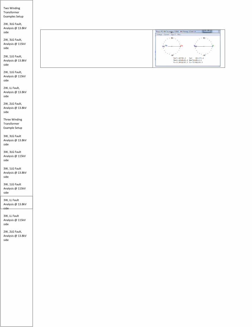
Two Winding Transformer Examples Setup
2W, 3LG Fault, Analysis @ 13.8kV side
2W, 3LG Fault, Analysis @ 115kV side 2W, 1LG Fault, Analysis @ 13.8kV side
2W, 1LG Fault, Analysis @ 115kV side
2W, LL Fault, Analysis @ 13.8kV side
2W, 2LG Fault, Analysis @ 13.8kV side
Three Winding Transformer Example Setup 3W, 3LG Fault Analysis @ 13.8kV side
3W, 3LG Fault Analysis @ 115kV side 3W, 1LG Fault Analysis @ 13.8kV side
3W, 1LG Fault Analysis @ 115kV side
3W, LL Fault Analysis @ 13.8kV side
3W, LL Fault Analysis @ 115kV side
2W, 2LG Fault, Analysis @ 13.8kV side
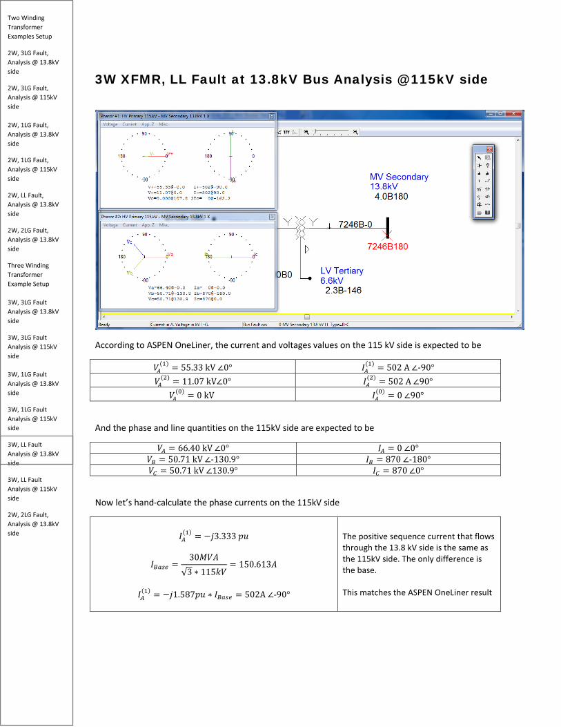
3W XFMR, LL Fault at 13.8kV Bus Analysis @ 115kV side
According to ASPEN OneLiner, the current and voltages values on the 115 kV side is expected to be
𝑘𝑘𝑀𝑀(1) = 55.33 kV ∠0° 𝐼𝐼𝑀𝑀
(1) = 502 A ∠-90° 𝑘𝑘𝑀𝑀
(2) = 11.07 kV∠0° 𝐼𝐼𝑀𝑀(2) = 502 A ∠90°
𝑘𝑘𝑀𝑀(0) = 0 kV 𝐼𝐼𝑀𝑀
(0) = 0 ∠90°
And the phase and line quantities on the 115kV side are expected to be
𝑘𝑘𝑀𝑀 = 66.40 kV ∠0° 𝐼𝐼𝑀𝑀 = 0 ∠0° 𝑘𝑘𝐵𝐵 = 50.71 kV ∠-130.9° 𝐼𝐼𝐵𝐵 = 870 ∠-180° 𝑘𝑘𝐶𝐶 = 50.71 kV ∠130.9° 𝐼𝐼𝐶𝐶 = 870 ∠0°
Now let’s hand-calculate the phase currents on the 115kV side
𝐼𝐼𝑀𝑀
(1) = −𝑗𝑗3.333 𝑝𝑝𝑝𝑝
𝐼𝐼𝐵𝐵𝑏𝑏𝑠𝑠𝑏𝑏 =30𝑀𝑀𝑘𝑘𝑀𝑀
√3 ∗ 115𝑘𝑘𝑘𝑘= 150.613𝑀𝑀
𝐼𝐼𝑀𝑀
(1) = −𝑗𝑗1.587𝑝𝑝𝑝𝑝 ∗ 𝐼𝐼𝐵𝐵𝑏𝑏𝑠𝑠𝑏𝑏 = 502A ∠-90°
The positive sequence current that flows through the 13.8 kV side is the same as the 115kV side. The only difference is the base. This matches the ASPEN OneLiner result

Two Winding Transformer Examples Setup
2W, 3LG Fault, Analysis @ 13.8kV side
2W, 3LG Fault, Analysis @ 115kV side 2W, 1LG Fault, Analysis @ 13.8kV side
2W, 1LG Fault, Analysis @ 115kV side
2W, LL Fault, Analysis @ 13.8kV side
2W, 2LG Fault, Analysis @ 13.8kV side
Three Winding Transformer Example Setup 3W, 3LG Fault Analysis @ 13.8kV side
3W, 3LG Fault Analysis @ 115kV side 3W, 1LG Fault Analysis @ 13.8kV side
3W, 1LG Fault Analysis @ 115kV side
3W, LL Fault Analysis @ 13.8kV side
3W, LL Fault Analysis @ 115kV side
2W, 2LG Fault, Analysis @ 13.8kV side
.
𝐼𝐼𝑀𝑀
(2) = +𝑗𝑗3.333𝑝𝑝𝑝𝑝
𝐼𝐼𝑀𝑀(2) = +𝑗𝑗3.333 𝑝𝑝𝑝𝑝 ∗ 𝐼𝐼𝐵𝐵𝑏𝑏𝑠𝑠𝑏𝑏 = 502A ∠90°
The negative sequence current has the same result except the angle is 180 degrees out of phase. This matches the ASPEN OneLiner result.
𝐼𝐼𝑀𝑀(0) = 0
We should not expect any zero sequence current since the sequence network is not activated. This matches the ASPEN OneLiner result.
The line current on the 115 kV side are calculated below.
𝐼𝐼𝑀𝑀 = 𝐼𝐼𝑀𝑀
(1) + 𝐼𝐼𝑀𝑀(2) = (-𝑗𝑗3.333 𝑝𝑝𝑝𝑝) + (𝑗𝑗3.333 𝑝𝑝𝑝𝑝) = 0 pu
𝐼𝐼𝑀𝑀 = 0
Using the principles of symmetrical components, we know that phase A current is the sum of positive, negative, and zero sequence currents. However, since the zero sequence is not activated, the result simply equal 0. This makes sense because this a phase B to C fault we should expect no fault current to flow on line a. This matches the ASPEN OneLiner result.

Two Winding Transformer Examples Setup
2W, 3LG Fault, Analysis @ 13.8kV side
2W, 3LG Fault, Analysis @ 115kV side 2W, 1LG Fault, Analysis @ 13.8kV side
2W, 1LG Fault, Analysis @ 115kV side
2W, LL Fault, Analysis @ 13.8kV side
2W, 2LG Fault, Analysis @ 13.8kV side
Three Winding Transformer Example Setup 3W, 3LG Fault Analysis @ 13.8kV side
3W, 3LG Fault Analysis @ 115kV side 3W, 1LG Fault Analysis @ 13.8kV side
3W, 1LG Fault Analysis @ 115kV side
3W, LL Fault Analysis @ 13.8kV side
3W, LL Fault Analysis @ 115kV side
2W, 2LG Fault, Analysis @ 13.8kV side
𝐼𝐼𝐵𝐵 = 𝑅𝑅2 ∗ 𝐼𝐼𝑀𝑀
(1) + 𝑅𝑅 ∗ 𝐼𝐼𝑀𝑀(2) + 𝐼𝐼𝑀𝑀
(0)
𝐼𝐼𝐵𝐵 = (1∠240°)(-𝑗𝑗3.333 𝑝𝑝𝑝𝑝) + (1∠120°)(+𝑗𝑗3.333 𝑝𝑝𝑝𝑝)= −5.772 𝑝𝑝𝑝𝑝
𝐼𝐼𝐵𝐵𝑏𝑏𝑠𝑠𝑏𝑏 =30𝑀𝑀𝑘𝑘𝑀𝑀
√3 ∗ 115𝑘𝑘𝑘𝑘= 150.613𝑀𝑀
𝐼𝐼𝐵𝐵 = −𝑗𝑗5.7622 𝑝𝑝𝑝𝑝 ∗ 𝐼𝐼𝐵𝐵𝑏𝑏𝑠𝑠𝑏𝑏 = 870𝑀𝑀 ∠-180°
To calculate Phase B current, we must shift the positive sequence current by 240 degrees CCW and negative sequence current by 120 degrees CCW per fundamentals of symmetrical components. Again, we omit the zero sequence current because it does not exist This result matches the ASPEN OneLiner simulation.
𝐼𝐼𝐶𝐶 = 𝑅𝑅 ∗ 𝐼𝐼𝑀𝑀
(1) + 𝑅𝑅2 ∗ 𝐼𝐼𝑀𝑀(2) + 𝐼𝐼𝑀𝑀
(0)
𝐼𝐼𝐵𝐵 = (1∠240°)(-𝑗𝑗3.333 𝑝𝑝𝑝𝑝) + (1∠120°)(+𝑗𝑗3.333 𝑝𝑝𝑝𝑝)= 5.772 𝑝𝑝𝑝𝑝
𝐼𝐼𝐵𝐵 = −𝑗𝑗5.7622 𝑝𝑝𝑝𝑝 ∗ 𝐼𝐼𝐵𝐵𝑏𝑏𝑠𝑠𝑏𝑏 = 870𝑀𝑀 ∠180°
To calculate Phase C current, we must shift the positive sequence current by 120 degrees CCW and negative sequence current by 240 degrees CCW per fundamentals of symmetrical components. Again, we omit the zero sequence current because it does not exist This result matches the ASPEN OneLiner simulation.
Now let’s calculate the sequence voltage on the 115kV side.
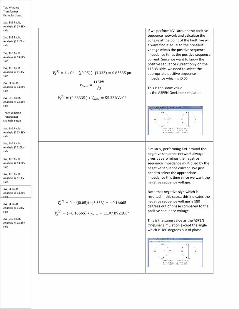
Two Winding Transformer Examples Setup
2W, 3LG Fault, Analysis @ 13.8kV side
2W, 3LG Fault, Analysis @ 115kV side 2W, 1LG Fault, Analysis @ 13.8kV side
2W, 1LG Fault, Analysis @ 115kV side
2W, LL Fault, Analysis @ 13.8kV side
2W, 2LG Fault, Analysis @ 13.8kV side
Three Winding Transformer Example Setup 3W, 3LG Fault Analysis @ 13.8kV side
3W, 3LG Fault Analysis @ 115kV side 3W, 1LG Fault Analysis @ 13.8kV side
3W, 1LG Fault Analysis @ 115kV side
3W, LL Fault Analysis @ 13.8kV side
3W, LL Fault Analysis @ 115kV side
2W, 2LG Fault, Analysis @ 13.8kV side
𝑘𝑘𝑀𝑀(1) = 1 ∠0° − (𝑗𝑗0.05)(−j3.333) = 0.83335 pu
𝑘𝑘𝐵𝐵𝑏𝑏𝑠𝑠𝑏𝑏 =115kV√3
𝑘𝑘𝑀𝑀
(1) = (0.83335 ) ∗ 𝑘𝑘𝐵𝐵𝑏𝑏𝑠𝑠𝑏𝑏 = 55.33 kV∠0°
If we perform KVL around the positive sequence network and calculate the voltage at the point of the fault, we will always find it equal to the pre-fault voltage minus the positive sequence impedance times the positive sequence current. Since we want to know the positive sequence current only on the 115 kV side, we need to select the appropriate positive sequence impedance which is j0.05 This is the same value as the ASPEN OneLiner simulation
𝑘𝑘𝑀𝑀(2) = 0 − (j0.05)(−j3.333) = −0.16665
𝑘𝑘𝑀𝑀
(2) = (−0.16665) ∗ 𝑘𝑘𝑏𝑏𝑏𝑏𝑠𝑠𝑏𝑏 = 11.07 kV∠180°
Similarly, performing KVL around the negative sequence network always gives us zero minus the negative sequence impedance multiplied by the negative sequence current. We just need to select the appropriate impedance this time since we want the negative sequence voltage. Note that negative sign which is resulted in this case… this indicates the negative sequence voltage is 180 degrees out of phase compared to the positive sequence voltage. This is the same value as the ASPEN OneLiner simulation except the angle which is 180 degrees out of phase.

Two Winding Transformer Examples Setup
2W, 3LG Fault, Analysis @ 13.8kV side
2W, 3LG Fault, Analysis @ 115kV side 2W, 1LG Fault, Analysis @ 13.8kV side
2W, 1LG Fault, Analysis @ 115kV side
2W, LL Fault, Analysis @ 13.8kV side
2W, 2LG Fault, Analysis @ 13.8kV side
Three Winding Transformer Example Setup 3W, 3LG Fault Analysis @ 13.8kV side
3W, 3LG Fault Analysis @ 115kV side 3W, 1LG Fault Analysis @ 13.8kV side
3W, 1LG Fault Analysis @ 115kV side
3W, LL Fault Analysis @ 13.8kV side
3W, LL Fault Analysis @ 115kV side
2W, 2LG Fault, Analysis @ 13.8kV side
𝑘𝑘𝑀𝑀(0) = 0
The zero sequence voltage will be zero since the Wye-ungrounded connection blocks the zero sequence current on the HV side. This is the same value as the ASPEN OneLiner simulation
Now let’s calculate the phase voltages on the 115 kV side.
𝑘𝑘𝑀𝑀 = 𝑘𝑘𝑀𝑀(1) + 𝑘𝑘𝑀𝑀
(2) + 𝑘𝑘𝑀𝑀(0)
𝑘𝑘𝑀𝑀 = 55.33 kV∠0° + 11.07 kV∠180° = 44.26 kV ∠0°
We must combine the positive, negative, and zero sequence voltages to calculate the phase A voltage seen on the 115kV. Note that zero sequence voltage is essentially 0 so we can omit this from our calculations 𝑘𝑘𝑀𝑀 is a very different value compared to ASPEN OneLiner. Please note that this is the un-faulted phase.
𝑘𝑘𝐵𝐵 = 𝑅𝑅2 ∗ 𝑘𝑘𝑀𝑀
(1) + 𝑅𝑅 ∗ 𝑘𝑘𝑀𝑀(2)
𝑘𝑘𝐵𝐵 = (1∠240°) ∗ 55.33 kV∠0° + (1∠120°) ∗ 11.07 kV∠180°
𝑘𝑘𝐵𝐵 = 61.61 kV∠-111.04°
Both the 𝑘𝑘𝐵𝐵, and 𝑘𝑘𝐶𝐶 hand calculated quantities are very different than ASPEN OneLiner. The reason for this difference is because we calculated the negative sequence voltage with an angle of 180 degrees instead of 0 degrees (𝑘𝑘𝑀𝑀
(2) = 11.07 kV∠180°). This makes a big difference with the unbalanced phasor additions.
𝑘𝑘𝐶𝐶 = 𝑅𝑅 ∗ 𝑘𝑘𝑀𝑀
(1) + 𝑅𝑅2 ∗ 𝑘𝑘𝑀𝑀(2) + 𝑘𝑘𝑀𝑀
(0) 𝑘𝑘𝐶𝐶 = (1∠120°) ∗ 55.33 kV∠0° + (1∠240°) ∗ 11.07 kV∠180°
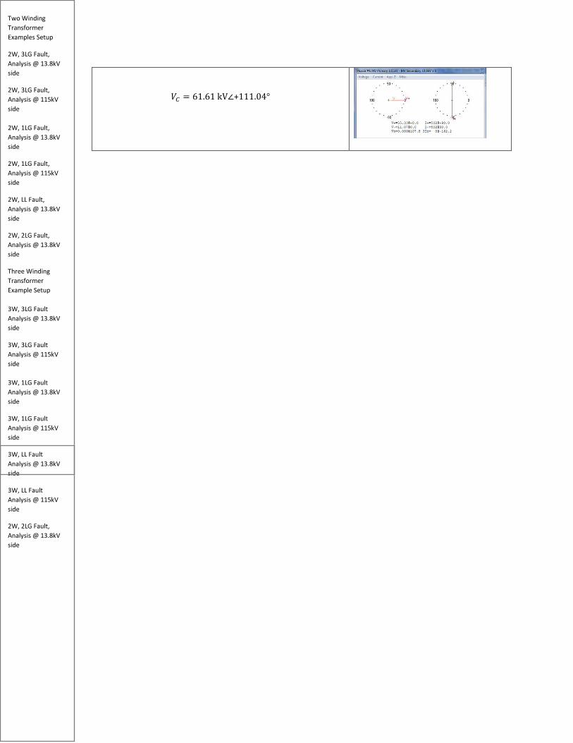
Two Winding Transformer Examples Setup
2W, 3LG Fault, Analysis @ 13.8kV side
2W, 3LG Fault, Analysis @ 115kV side 2W, 1LG Fault, Analysis @ 13.8kV side
2W, 1LG Fault, Analysis @ 115kV side
2W, LL Fault, Analysis @ 13.8kV side
2W, 2LG Fault, Analysis @ 13.8kV side
Three Winding Transformer Example Setup 3W, 3LG Fault Analysis @ 13.8kV side
3W, 3LG Fault Analysis @ 115kV side 3W, 1LG Fault Analysis @ 13.8kV side
3W, 1LG Fault Analysis @ 115kV side
3W, LL Fault Analysis @ 13.8kV side
3W, LL Fault Analysis @ 115kV side
2W, 2LG Fault, Analysis @ 13.8kV side
𝑘𝑘𝐶𝐶 = 61.61 kV∠+111.04°

Two Winding Transformer Examples Setup
2W, 3LG Fault, Analysis @ 13.8kV side
2W, 3LG Fault, Analysis @ 115kV side 2W, 1LG Fault, Analysis @ 13.8kV side
2W, 1LG Fault, Analysis @ 115kV side
2W, LL Fault, Analysis @ 13.8kV side
2W, 2LG Fault, Analysis @ 13.8kV side
Three Winding Transformer Example Setup 3W, 3LG Fault Analysis @ 13.8kV side
3W, 3LG Fault Analysis @ 115kV side 3W, 1LG Fault Analysis @ 13.8kV side
3W, 1LG Fault Analysis @ 115kV side
3W, LL Fault Analysis @ 13.8kV side
3W, LL Fault Analysis @ 115kV side
2W, 2LG Fault, Analysis @ 13.8kV side
3W XFMR, 2LG Fault at 13.8kV Bus Analysis @ 13.8kV side

Two Winding Transformer Examples Setup
2W, 3LG Fault, Analysis @ 13.8kV side
2W, 3LG Fault, Analysis @ 115kV side 2W, 1LG Fault, Analysis @ 13.8kV side
2W, 1LG Fault, Analysis @ 115kV side
2W, LL Fault, Analysis @ 13.8kV side
2W, 2LG Fault, Analysis @ 13.8kV side
Three Winding Transformer Example Setup 3W, 3LG Fault Analysis @ 13.8kV side
3W, 3LG Fault Analysis @ 115kV side 3W, 1LG Fault Analysis @ 13.8kV side
3W, 1LG Fault Analysis @ 115kV side
3W, LL Fault Analysis @ 13.8kV side
3W, LL Fault Analysis @ 115kV side
2W, 2LG Fault, Analysis @ 13.8kV side
References Grainger, John J., et al. Power System Analysis. McGraw-Hill Education, 2016.
Blackburn, Lewis J. “Protective Relaying: Principles and Applications, Fourth Edition.” CRC Press
Jason Hall PE, Steve Cresse PE, Phil Tibbits PE, Casey Harmin PE – co-workers