Circular mode: A new scanning probe microscopy method for ...mazeran/20.pdf · investigating...
7
Circular mode: A new scanning probe microscopy method for investigating surface properties at constant and continuous scanning velocities Hussein Nasrallah, Pierre-Emmanuel Mazeran, and Olivier Noël Citation: Rev. Sci. Instrum. 82, 113703 (2011); doi: 10.1063/1.3658049 View online: http://dx.doi.org/10.1063/1.3658049 View Table of Contents: http://rsi.aip.org/resource/1/RSINAK/v82/i11 Published by the American Institute of Physics. Related Articles Adhesion selectivity by electrostatic complementarity. II. Two-dimensional analysis J. Appl. Phys. 110, 054903 (2011) Effects of rhenium alloying on adhesion of Mo/HfC and Mo/ZrC interfaces: A first-principles study J. Appl. Phys. 110, 044901 (2011) Surface acoustic wave velocity of gold films deposited on silicon substrates at different temperatures J. Appl. Phys. 110, 023503 (2011) High resolution study of the strong diamond/silicon nitride interface Appl. Phys. Lett. 98, 171913 (2011) General hypothesis and shell model for the synthesis of semiconductor nanotubes, including carbon nanotubes J. Appl. Phys. 108, 064323 (2010) Additional information on Rev. Sci. Instrum. Journal Homepage: http://rsi.aip.org Journal Information: http://rsi.aip.org/about/about_the_journal Top downloads: http://rsi.aip.org/features/most_downloaded Information for Authors: http://rsi.aip.org/authors Downloaded 21 Nov 2011 to 195.83.155.55. Redistribution subject to AIP license or copyright; see http://rsi.aip.org/about/rights_and_permissions
Transcript of Circular mode: A new scanning probe microscopy method for ...mazeran/20.pdf · investigating...

Circular mode: A new scanning probe microscopy method forinvestigating surface properties at constant and continuous scanningvelocitiesHussein Nasrallah, Pierre-Emmanuel Mazeran, and Olivier Noël Citation: Rev. Sci. Instrum. 82, 113703 (2011); doi: 10.1063/1.3658049 View online: http://dx.doi.org/10.1063/1.3658049 View Table of Contents: http://rsi.aip.org/resource/1/RSINAK/v82/i11 Published by the American Institute of Physics. Related ArticlesAdhesion selectivity by electrostatic complementarity. II. Two-dimensional analysis J. Appl. Phys. 110, 054903 (2011) Effects of rhenium alloying on adhesion of Mo/HfC and Mo/ZrC interfaces: A first-principles study J. Appl. Phys. 110, 044901 (2011) Surface acoustic wave velocity of gold films deposited on silicon substrates at different temperatures J. Appl. Phys. 110, 023503 (2011) High resolution study of the strong diamond/silicon nitride interface Appl. Phys. Lett. 98, 171913 (2011) General hypothesis and shell model for the synthesis of semiconductor nanotubes, including carbon nanotubes J. Appl. Phys. 108, 064323 (2010) Additional information on Rev. Sci. Instrum.Journal Homepage: http://rsi.aip.org Journal Information: http://rsi.aip.org/about/about_the_journal Top downloads: http://rsi.aip.org/features/most_downloaded Information for Authors: http://rsi.aip.org/authors
Downloaded 21 Nov 2011 to 195.83.155.55. Redistribution subject to AIP license or copyright; see http://rsi.aip.org/about/rights_and_permissions

REVIEW OF SCIENTIFIC INSTRUMENTS 82, 113703 (2011)
Circular mode: A new scanning probe microscopy method for investigatingsurface properties at constant and continuous scanning velocities
Hussein Nasrallah,1 Pierre-Emmanuel Mazeran,2,a) and Olivier Noël11Molecular Landscapes and Biophotonic Skyline Group, Laboratoire de Physique de l’Etat Condensé,CNRS-UMR 6087, Université du Maine, Avenue Olivier Messiaen, 72085 Le Mans Cedex 9, France2Laboratoire Roberval, CNRS-UMR 6253, Université de Technologie de Compiègne, BP 20529, 60205Compiègne Cedex, France
(Received 7 June 2011; accepted 11 October 2011; published online 8 November 2011)
In this paper, we introduce a novel scanning probe microscopy mode, called the circular mode, whichoffers expanded capabilities for surface investigations especially for measuring physical propertiesthat require high scanning velocities and/or continuous displacement with no rest periods. To achievethese specific conditions, we have implemented a circular horizontal displacement of the probe rela-tive to the sample plane. Thus the relative probe displacement follows a circular path rather than theconventional back and forth linear one. The circular mode offers advantages such as high and constantscanning velocities, the possibility to be combined with other classical operating modes, and a simplercalibration method of the actuators generating the relative displacement. As application examples ofthis mode, we report its ability to (1) investigate the influence of scanning velocity on adhesion forces,(2) measure easily and instantly the friction coefficient, and (3) generate wear tracks very rapidly fortribological investigations. © 2011 American Institute of Physics. [doi:10.1063/1.3658049]
I. INTRODUCTION
The advent of scanning probe microscopes (SPMs) andespecially of the atomic force microscope (AFM) haveopened new perspectives for investigating at the nanoscalephenomenological mechanisms that are encountered in dif-ferent fields such as material science, biology, tribology, thinfilms, microelectronics,1, 2 etc. The SPM principle is based onmeasuring interaction forces between the probe and a sample.Conventionally, the SPM is employed for imaging surface to-pography with high resolution either in dynamic modes3, 4 orcontact modes.5 For this application, the scanning motion ofthe probe relative to the plane of the surface is a back andforth displacement with amplitudes ranging from 10 nm upto 100 μm and frequencies usually ranging from 0.1 up to10 Hz. It also offers the capability of measuring probe-sampleinteractions as a function of their separation distance (forcespectrum).6 Finally, it has evolved into a versatile instrumentfor measuring physical properties such as friction,7 resistivity,capacitance,8 etc.
Despite the various modifications that have been intro-duced to the basic SPM setup for expanding and improvingits measurement capabilities, there still remain multiple chal-lenges that hinder the accuracy of the experimental proce-dures. As a main limitation, the conventional back and forthscanning motion of the probe that results in rest periods whenthe direction of the scan is inverted. During these rest peri-ods, the characteristics of the nanoscale probe-sample inter-action may change significantly. For example, in the case ofhydrophilic surfaces, the probe-sample contact may evolvedue to the formation of a water meniscus when the contactis at rest for a few milliseconds.9 This leads to a capillary
a)Author to whom correspondence should be addressed. Electronic mail:[email protected].
force that acts as an additional normal load.10 Consequently,the resulting adhesion forces induced by the evolving menis-cus are never constant and the average value of the adhesionforce depends on experimental conditions (scanning lengthand frequency, etc.). The scan inversion may also change sig-nificantly the probe-sample interactions such as shear stress.As a consequence, while experimenting under conventionalscanning conditions, the measurements of the probe-sampleinteractions are always conducted in a non-stationary state.
To address this problem, we present an innovative SPMsetup that allows achieving a circular displacement of theprobe relative to the sample rather than a back and forth lin-ear displacement. This new SPM mode is called the circu-lar mode.11 This original mode offers significant advantagessuch as: (1) allowing collection of data at constant and con-tinuous velocities without any halt during the entire scan du-ration (if no stick-slip effect is considered) and thus to at-tain stationary state and (2) reaching high scanning velocitieshigher than 100 000 μm s−1. Such advantages are determiningin physics for quantitative measurements at a local scale thatrequire high-speed displacements or if the probe-sample inter-action could be influenced by rest periods, acceleration, decel-eration, or non-constant velocities. In the following, we willpresent the experimental setup of the circular mode. Then,we will report some experimental data that demonstrate thescientific potential of this new mode in a wide variety ofapplications.
II. CIRCULAR MODE: EXPERIMENTAL SETUP
The SPM is dependent of three components: the mostsensitive component which is the probe that interacts di-rectly with the sample surface, the photo detector that sensesthe changes in the angle of the reflected beam due to the
0034-6748/2011/82(11)/113703/6/$30.00 © 2011 American Institute of Physics82, 113703-1
Downloaded 21 Nov 2011 to 195.83.155.55. Redistribution subject to AIP license or copyright; see http://rsi.aip.org/about/rights_and_permissions
113703-2 Nasrallah, Mazeran, and Noël Rev. Sci. Instrum. 82, 113703 (2011)
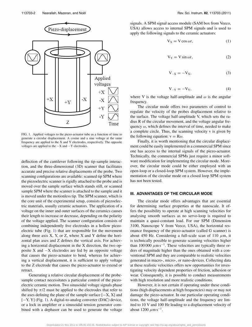
FIG. 1. Applied voltages to the piezo-actuator tube as a function of time togenerate a circular displacement. A cosine and a sine voltage at the samefrequency are applied to the X and Y electrodes, respectively. The oppositevoltages are applied to the −X and −Y electrodes.
deflection of the cantilever following the tip-sample interac-tion, and the three-dimensional (3D) scanner that facilitatesaccurate and precise relative displacements of the probe. Twoscanning configurations are available: scanned tip SPM wherethe piezoelectric scanner is rigidly attached to the probe and ismoved over the sample surface which stands still, or scannedsample SPM where the scanner is attached to the sample and itis moved under the motionless tip. The SPM scanner, which isthe core unit of the experimental setup, consists of piezoelec-tric materials, usually ceramic actuators. The application of avoltage on the inner and outer surfaces of the ceramics causestheir length to increase or decrease, depending on the polarityof the voltage applied. The scanner configuration consists ofcombining independently five electrodes in a hollow piezo-electric tube (Fig. 1) that are responsible for the movementalong three axis X, Y, or Z, where X and Y define the hori-zontal plan axes and Z defines the vertical axis. For achiev-ing a horizontal displacement in the X direction, the two op-posite X and −X electrodes are fed by an opposite voltagethat causes the piezo-actuator to bend, whereas for achiev-ing a vertical displacement, it is sufficient to apply voltageto the Z electrode that causes the piezo-actuator to extend orretract.
Generating a relative circular displacement of the probe-sample contact necessitates a particular control of the piezo-electric ceramic motion. Two sinusoidal voltage signals phaseshifted by π /2 must be applied to the electrodes that refer tothe axes defining the plane of the sample surface [−X, X] and[−Y, Y] (Fig. 1). A digital-to-analog converter (DAC) device,or a lock in amplifier or a sinusoidal tension generator com-bined with a dephasor can be used to generate the voltage
signals. A SPM signal access module (SAM box from Veeco,USA) allows access to internal SPM signals and is used toapply the following signals to the ceramic actuators:
VX = V cos ωt, (1)
VY = V sin ωt, (2)
V−X = −VX, (3)
V−Y = −VY, (4)
where V is the voltage half-amplitude and ω is the angularfrequency.
The circular mode offers two parameters of control toregulate the velocity of the probes displacement relative tothe surface. The voltage half-amplitude V, which sets the ra-dius R of the circular movement, and the voltage angular fre-quency ω, which defines the interval of time, needed to makea complete circle. Thus, the scanning velocity v is given bythe following equation: v = Rω.
Finally, it is worth mentioning that the circular displace-ment could be easily implemented in a commercial SPM sinceone has access to the internal signals of the piezo-actuator.Technically, the commercial SPMs just require a minor soft-ware modification for implementing the circular mode. More-over, the circular mode could be either employed with anopen-loop or a closed-loop SPM system. However, the imple-mentation of the circular mode on a closed loop SPM systemhas not been tested.
III. ADVANTAGES OF THE CIRCULAR MODE
The circular mode offers advantages that are essentialfor determining surface properties at the nanoscale. It of-fers the possibility to operate at high scanning velocities foranalysing smooth surfaces as no servo-loop is required tomaintain a quasi-constant load. For our SPM (Dimension3100, Nanoscope V from Veeco, USA), the horizontal res-onance frequency of the piezo-actuator (called G scanner) isabout 450 Hz. Considering a full-scale scan of 110 μm, itis technically possible to generate scanning velocities higherthan 100 000 μm s−1. These velocities are typically three or-ders of magnitude higher than the ones obtained with a con-ventional SPM and they are comparable to realistic velocitiesgenerated in macro-, micro-, or nano-devices. Collecting dataat these realistic velocities offers new opportunities for inves-tigating velocity dependent properties of friction, adhesion orwear. Consequently, it is possible to conduct measurementswith high resolution and more realistic conditions.
However, it is not certain if operating under these condi-tions (high displacements at high frequencies) may or may notdamage the piezo-actuator. In our particular operating condi-tions, the voltage half-amplitude and the frequency are lim-ited to 10 V and 100 Hz leading to a displacement velocity ofabout 1200 μm s−1.
Downloaded 21 Nov 2011 to 195.83.155.55. Redistribution subject to AIP license or copyright; see http://rsi.aip.org/about/rights_and_permissions

113703-3 Nasrallah, Mazeran, and Noël Rev. Sci. Instrum. 82, 113703 (2011)
A further benefit of the circular mode is the continuousand constant scanning motion which allows avoiding incon-veniences caused by the rest periods of the probe resultingfrom the abrupt inversion of the scanning motion encounteredwhen using the conventional back and forth scan mode.
Moreover, for an open-loop SPM system, the circularmode needs a far less complicated method for calibrating thepiezo-actuator displacement. Indeed, in classical SPM scan-ning, back and forth scans are realized in the so-called fastscan direction. These consecutive scans are slightly shiftedperpendicular to the fast scan direction (called the slow scandirection) and are added one by one to form the image. Be-cause of the nonlinearity and creep of the piezo-actuator, thevoltages applied on the two directions of the piezo-actuatorfollow a complex equation that requires the calibration ofthree parameters to generate a voltage function that conductsto a linear scan.12 In particular, the G scanner (Veeco, USA)requires the calibration of 14 parameters that are determinedthrough a relatively long and complex calibration process.However, when using the circular mode, there are no more fastand low scanning directions. The voltage sent to the piezo-actuator is sinusoidal with respect to time for the two hor-izontal directions. Thus, one should only consider the non-linearity of the scanner sensitivity for each direction leadingto a simpler and reliable piezo-actuator calibration. Practi-cally, the calibration of the piezo-actuator for obtaining anaccurate circular motion of the probe can be easily realisedusing three different methods: (1) The classical calibrationmethod that requires the use of a reference sample such asa calibration grid. In this case, the authors propose to im-pose sinusoidal voltages of various amplitudes in either theX or Y direction and to measure the resulting displacement.This method is mostly adapted for low frequency displace-ments as an effective servo-loop is required to generate the“height” signal. (2) The circular displacement could be cali-brated with the displacement sensors of a closed-loop SPM iftheir working frequencies are compatible with the frequencyof the circular displacement. (3) The last method consists inmeasuring the dimension of a circular track due to wear orplastic deformation obtained with the circular mode at a fixedamplitude and frequency. This is particularly interesting as itis simple, fast, and reliable even if it is less accurate than theconventional method due to the error source on the width ofthe track. This method is especially adapted when the piezo-actuator is used at high frequencies since the servo-loop isgenerally not efficient at these frequencies. Figure 2 clearlyshows the evidence of a circular track due to wear gener-ated by the circular motion of the tip-sample contact. Obvi-ously, this method is damaging for both the sample and theprobe.
Finally, another interesting feature of the circular mode isthat along with the possibility of combining the circular modeto the classical modes, as adhesion force mode or frictionforce mode. Consequently, it is possible to measure simul-taneously adhesion forces or friction forces while the relativeprobe-sample displacement is circular. Such advantages of thecircular mode can be essential for metrological applications.The main characteristics of the circular mode are summarizedin Table I.
FIG. 2. AFM topographic image of a GaAs thin film surface (image size: 3μm × 3 μm). The circular track is created by the circular displacement of theprobe relative to the sample in using the circular mode at a sliding velocity of1000 μm s−1 for three consecutive minutes, under a load of 80 nN.
IV. APPLICATION EXAMPLES OF THE CIRCULARMODE IN NANOTRIBOLOGY
A. Coupling the circular mode with other mode:Measurements of adhesion forces at differentsliding velocities
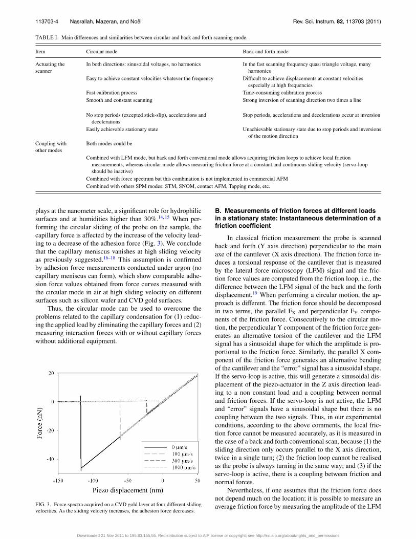
Conventional AFM force mode allows the measuring ofthe adhesion force by means of a force spectrum.6, 10 Theforce spectrum is obtained by imposing back and forth ver-tical displacements to the piezo-actuator. It is possible tocombine the circular mode with the conventional force spec-trum. In such case, one can acquire force spectrum while theprobe is scanning in a circular motion at a fixed velocity. Thisis advantageous for investigating the sliding velocity depen-dence of the attractive and adhesive forces. Force-distancemeasurements combined to the circular mode were conductedon various hydrophilic surfaces (mica, silicon nitride, siliconwafer, chemical vapour deposited (CVD) gold surfaces) at arelative humidity close to 40% in air. Figure 3 shows theforce-distance spectrum obtained on gold for four sliding ve-locities. The four velocities are obtained by imposing a cir-cular displacement at a frequency of 100 Hz with a diameterof 0, 0.32, 0.95, and 3.2 μm, respectively. The correspond-ing applied voltage is computed based on the calibration ofthe piezo scanner using the wear track method described pre-viously. Voltage signals applied to the piezo-actuators weregenerated by a homemade software and a DAC card and sentto the 3D scanner via the SAM box (Veeco, USA). The verti-cal displacement was set to 500 nm at a frequency of 0.1 Hzcorresponding to a vertical velocity of 0.1 μm s−1. The adhe-sion forces corresponding to the jump-off cantilever deflec-tion (Fig. 3) is decreasing with an increase of the sliding ve-locities. At high sliding velocities, the adhesion force reachesa minimum value that remains constant and equal to the at-tractive force.13 To explain such a behaviour, it is well knownthat the capillary force between the probe and the sample
Downloaded 21 Nov 2011 to 195.83.155.55. Redistribution subject to AIP license or copyright; see http://rsi.aip.org/about/rights_and_permissions
113703-4 Nasrallah, Mazeran, and Noël Rev. Sci. Instrum. 82, 113703 (2011)
TABLE I. Main differences and similarities between circular and back and forth scanning mode.
Item Circular mode Back and forth mode
Actuating thescanner
In both directions: sinusoidal voltages, no harmonics In the fast scanning frequency quasi triangle voltage, manyharmonics
Easy to achieve constant velocities whatever the frequency Difficult to achieve displacements at constant velocitiesespecially at high frequencies
Fast calibration process Time-consuming calibration processSmooth and constant scanning Strong inversion of scanning direction two times a line
No stop periods (excepted stick-slip), accelerations anddecelerations
Stop periods, accelerations and decelerations occur at inversion
Easily achievable stationary state Unachievable stationary state due to stop periods and inversionsof the motion direction
Coupling withother modes
Both modes could be
Combined with LFM mode, but back and forth conventional mode allows acquiring friction loops to achieve local frictionmeasurements, whereas circular mode allows measuring friction force at a constant and continuous sliding velocity (servo-loopshould be inactive)
Combined with force spectrum but this combination is not implemented in commercial AFMCombined with others SPM modes: STM, SNOM, contact AFM, Tapping mode, etc.
plays at the nanometer scale, a significant role for hydrophilicsurfaces and at humidities higher than 30%.14, 15 When per-forming the circular sliding of the probe on the sample, thecapillary force is affected by the increase of the velocity lead-ing to a decrease of the adhesion force (Fig. 3). We concludethat the capillary meniscus vanishes at high sliding velocityas previously suggested.16–18 This assumption is confirmedby adhesion force measurements conducted under argon (nocapillary meniscus can form), which show comparable adhe-sion force values obtained from force curves measured withthe circular mode in air at high sliding velocity on differentsurfaces such as silicon wafer and CVD gold surfaces.
Thus, the circular mode can be used to overcome theproblems related to the capillary condensation for (1) reduc-ing the applied load by eliminating the capillary forces and (2)measuring interaction forces with or without capillary forceswithout additional equipment.
FIG. 3. Force spectra acquired on a CVD gold layer at four different slidingvelocities. As the sliding velocity increases, the adhesion force decreases.
B. Measurements of friction forces at different loadsin a stationary state: Instantaneous determination of afriction coefficient
In classical friction measurement the probe is scannedback and forth (Y axis direction) perpendicular to the mainaxe of the cantilever (X axis direction). The friction force in-duces a torsional response of the cantilever that is measuredby the lateral force microscopy (LFM) signal and the fric-tion force values are computed from the friction loop, i.e., thedifference between the LFM signal of the back and the forthdisplacement.19 When performing a circular motion, the ap-proach is different. The friction force should be decomposedin two terms, the parallel FX and perpendicular FY compo-nents of the friction force. Consecutively to the circular mo-tion, the perpendicular Y component of the friction force gen-erates an alternative torsion of the cantilever and the LFMsignal has a sinusoidal shape for which the amplitude is pro-portional to the friction force. Similarly, the parallel X com-ponent of the friction force generates an alternative bendingof the cantilever and the “error” signal has a sinusoidal shape.If the servo-loop is active, this will generate a sinusoidal dis-placement of the piezo-actuator in the Z axis direction lead-ing to a non constant load and a coupling between normaland friction forces. If the servo-loop is not active, the LFMand “error” signals have a sinusoidal shape but there is nocoupling between the two signals. Thus, in our experimentalconditions, according to the above comments, the local fric-tion force cannot be measured accurately, as it is measured inthe case of a back and forth conventional scan, because (1) thesliding direction only occurs parallel to the X axis direction,twice in a single turn; (2) the friction loop cannot be realisedas the probe is always turning in the same way; and (3) if theservo-loop is active, there is a coupling between friction andnormal forces.
Nevertheless, if one assumes that the friction force doesnot depend much on the location; it is possible to measure anaverage friction force by measuring the amplitude of the LFM
Downloaded 21 Nov 2011 to 195.83.155.55. Redistribution subject to AIP license or copyright; see http://rsi.aip.org/about/rights_and_permissions

113703-5 Nasrallah, Mazeran, and Noël Rev. Sci. Instrum. 82, 113703 (2011)
FIG. 4. Adhesion and friction spectra conducted on a gold sample at a slidingvelocity of 300 μm s−1, show simultaneous acquisition of the normal (a) andfriction force (b) as a function of the piezo-actuator displacement. The graphallows direct computation of the friction-load dependence.
signal during circular motion and without using the servo-loop. Previous authors have suggested similar method usinglateral force modulation20–22 but the circular mode offers theadvantage of reaching high, constant and continuous slidingvelocities and thus stationary states. A lock-in-amplifier en-ables measuring the amplitude of the LFM signal at the fre-quency of the circular movement and thus measuring directlythe friction force. In combining the circular and force spec-trum mode, it is therefore possible to obtain simultaneouslyadhesion and friction-load spectra (Fig. 4). One can rapidlyand easily acquire the friction-load dependent curve, whichrequires time-consuming experiments with the conventionalAFM mode.
Concerning the calibration of the lateral force, it couldbe carried out using the classical methods developed for cali-brating the LFM signal using the back and forth method sincelateral forces in circular mode are also measured from thetorsion of the cantilever. For these experiments, the lateralforce signal has been calibrated using the method proposedby Ogletree et al.19
In our experiments, the Amontons law, which predicts alinear dependence between friction and load, is verified. Theslope of the friction force versus the load curve gives directlythe value of the friction coefficient (Fig. 4(b)). In this exam-ple, we obtain a fiction coefficient of 0.085 for a gold CVDlayer and a sliding velocity of 300 μm s−1.
C. Using the circular mode at high sliding velocity:Fast achievement of wear tracks
Wear can be defined as a process in which interactionsof the surfaces or bounding faces of a solid with its workingenvironment results in dimensional loss of the solid. A seri-ous issue is that wear rate is known to depend strongly on themagnitude of the loading force, leading to a dramatic varia-tion of the wear rate as the sliding conditions change. How-ever, for different operating conditions (materials, geometry,roughness, humidity, etc.) and sliding velocities, friction andwear are dominated by different mechanisms.2, 7, 23 Further-more, wear at the nanometer scale is generally a slow processthat results in low depth wear tracks that are difficult to mea-sure. The circular mode helps to investigate the evidence of
FIG. 5. Wear track obtained with the circular mode on a GaAs, sample (a)magnified image of the track generated by the circular motion for 3 consecu-tive minutes, under a load of 80 nN at a sliding velocity of 1000 μm s−1. (b)Profile showing the depth of the track.
Downloaded 21 Nov 2011 to 195.83.155.55. Redistribution subject to AIP license or copyright; see http://rsi.aip.org/about/rights_and_permissions

113703-6 Nasrallah, Mazeran, and Noël Rev. Sci. Instrum. 82, 113703 (2011)
wear by increasing the sliding velocity and thus generating afaster wear process. For example, an experiment conducted ona gallium arsenide (GaAs) sample with a silicon nitride probe,at a load of 80 nN and at a sliding velocity of 1000 μm s−1
requires 3 min to generate a track, which is about 0.5 nm indepth (Fig. 5). The equivalent experiment conducted with aconventional AFM needs about thirty minutes. This durationis generally too long to prevent any drift of the piezo-actuatorthat disturbs the measurements.
The circular mode could be employed for tribological in-vestigations as, for example, understanding the mechanismsimplicated in wear or characterizing wear properties of mate-rials. In a more general way, the circular mode could be em-ployed for changing rapidly the surface properties that can bemodified by the probe-sample interactions. As examples, (1)circular features generated by wear tracks, lithography, oxi-dation, or any modifications of the physical surface proper-ties (magnetic, electrostatic, etc.) could be employed for datastorage and (2) the circular mode could be employed to polishsurfaces or for machining surfaces by wear, by combining thecircular mode with a translation displacement. It is possibleto generate easily and rapidly surface features of any form bythis process by using abrasive probes such as diamond-coatedprobes.
V. CONCLUSION
The patented circular mode11 generates continuous andconstant circular probe displacements at potentially very highvelocities that are three orders of magnitude higher than con-ventional SPM velocities and that approximate to those metin realistic cases. Because the relative probe displacement iscircular, the probe velocity is constant without acceleration,deceleration or discontinuation. Therefore, it offers new op-portunities and new approaches of measuring probe-sampleinteraction especially when stationary states are required. Thecircular mode could be employed independently or could becombined with other SPM modes as for example conventionalforce-spectrum mode.
We have illustrated the interest of the circular mode bypresenting its ability to (1) measure the influence of the slid-ing velocity on adhesion forces, (2) measure easily and in-stantaneously the friction-load dependence, and (3) generatefast consequent wear track.
Many other applications for characterizing surface prop-erties could be visualized by the SPM community for theirspecial needs by implementing the circular mode either onan AFM or on any other member of the SPM family (scan-ning tunnelling microscope (STM), scanning near-field op-tical microscope (SNOM), etc.). Therefore, this new SPMmode appears to be a powerful tool to get new insights inmany research fields such as mechanics, physics, biology, orfor metrological purposes.
ACKNOWLEDGMENTS
This work has been supported by the “Agence Nationalepour la Recherche” (ANR) under Contract No. ANR-08-JCJC-0051-01.
1M. Jaschke, H.-J. Butt, S. Manne, H. E. Gaub, O. Hasemann, F. Krimphove,and E. K. Wolff, Biosens. Bioelectron. 11, 601 (1996).
2E. Meyer, R. Overney, K. Dransfeld, and T. Gyalog, Nanoscience: Fric-tion and Rheology on the Nanometer Scale (World Scientific Publishing,London, 1998).
3R. Erlandsson, L. Olsson, and P. Mårtensson, Phys. Rev. B 54, R8309(1996)
4S. Belikov and S. Magonov, Jpn. J. Appl. Phys. 45, 2158 (2006).5F. Ohnesorge and G. Binnig, Science 260,1451 (1993).6H.-J. Butt, B. Cappella, and M. Kappl, Surf. Sci. Rep. 59, 1 (2005).7R. W. Carpick and M. Salmeron, Chem. Rev. 97, 1163 (1997).8F. Houze, P. Chretien, O. Schneegans, R. Meyer, and L. Boyer, Appl. Phys.Lett. 86, 123103 (2005).
9R. Szoszkiewicz and E. Riedo, Phys. Rev. Lett. 95, 135502 (2005).10A. L. Weisenhorn, P. K. Hansma, T. R. Albrecht, and C. F. Quate, Appl.
Phys. Lett. 54, 2651 (1989).11O. Noel, P.-E. Mazeran, and H. Nasrallah, Patent PCT/FR2011/051024
(September 24, 1991).12V. B. Elings and J. A. Gurley, U.S. patent 5,051,646 (May 5, 2011).13O. Noel, P.-E. Mazeran, and H. Nasrallah, “Velocity dependence of adhe-
sion in a sliding nanometer-sized contact,” Phys. Rev. Lett. (submitted).14D. L. Sedin and K. L. Rowlen, Anal. Chem. 72,2183 (2000).15J. N. Israelachvili, Intermolecular and Surface Forces (Academic, San
Diego, 1991).16L. Sirghi, Appl. Phys. Lett. 82, 3755 (2003).17E. Riedo, F. Lévy, and H. Brune, Phys. Rev. Lett. 88, 185505 (2002).18P.-E. Mazeran, Mater. Sci. Eng., C 26, 751 (2006).19D. F. Ogletree, R. W. Carpick, and M. Salmeron, Rev. Sci. Instrum. 67,
3298 (1996).20J. Colchero, M. Luna and A. M. Baro, Appl. Phys. Lett. 68, 2896 (1996).21P.-E. Mazeran and J.-L. Loubet, Tribol. Lett. 7, 199 (1999).22P.-E. Mazeran and M. Beyaoui, Tribol. Lett. 30, 1 (2008).23C. M. Mate, Tribology on the Small Scale a Bottom Up Approach to Fric-
tion, Lubrication, and Wear (Oxford University Press, Oxford/New York,2008).
Downloaded 21 Nov 2011 to 195.83.155.55. Redistribution subject to AIP license or copyright; see http://rsi.aip.org/about/rights_and_permissions