
CIC MegaCore Function User Guide - Altera 2014 Altera Corporation CIC MegaCore Function User Guide...
34
101 Innovation Drive San Jose, CA 95134 www.altera.com UG-CIC-14.1 User Guide CIC MegaCore Function Feedback Subscribe CIC MegaCore Function User Guide
Transcript of CIC MegaCore Function User Guide - Altera 2014 Altera Corporation CIC MegaCore Function User Guide...

101 Innovation DriveSan Jose, CA 95134www.altera.com
UG-CIC-14.1
User Guide
CIC MegaCore Function
Feedback Subscribe
CIC MegaCore Function User Guide

© 2014 Altera Corporation. All rights reserved. ALTERA, ARRIA, CYCLONE, HARDCOPY, MAX, MEGACORE, NIOS, QUARTUS and STRATIX words and logosare trademarks of Altera Corporation and registered in the U.S. Patent and Trademark Office and in other countries. All other words and logos identified astrademarks or service marks are the property of their respective holders as described at www.altera.com/common/legal.html. Altera warrants performance of itssemiconductor products to current specifications in accordance with Altera's standard warranty, but reserves the right to make changes to any products andservices at any time without notice. Altera assumes no responsibility or liability arising out of the application or use of any information, product, or servicedescribed herein except as expressly agreed to in writing by Altera. Altera customers are advised to obtain the latest version of device specifications before relyingon any published information and before placing orders for products or services.
August 2014 Altera Corporation CIC MegaCore FunctionUser Guide
ISO 9001:2008 Registered

August 2014 Altera Corporation
Contents
Chapter 1. About This MegaCore FunctionFeatures . . . . . . . . . . . . . . . . . . . . . . . . . . . . . . . . . . . . . . . . . . . . . . . . . . . . . . . . . . . . . . . . . . . . . . . . . . . . . . . . 1–1Release Information . . . . . . . . . . . . . . . . . . . . . . . . . . . . . . . . . . . . . . . . . . . . . . . . . . . . . . . . . . . . . . . . . . . . . 1–1Device Family Support . . . . . . . . . . . . . . . . . . . . . . . . . . . . . . . . . . . . . . . . . . . . . . . . . . . . . . . . . . . . . . . . . . . 1–2MegaCore Verification . . . . . . . . . . . . . . . . . . . . . . . . . . . . . . . . . . . . . . . . . . . . . . . . . . . . . . . . . . . . . . . . . . . 1–2Performance and Resource Utilization . . . . . . . . . . . . . . . . . . . . . . . . . . . . . . . . . . . . . . . . . . . . . . . . . . . . . . 1–3
Chapter 2. Getting StartedInstalling and Licensing IP Cores . . . . . . . . . . . . . . . . . . . . . . . . . . . . . . . . . . . . . . . . . . . . . . . . . . . . . . . . . . 2–1 . . . . . . . . . . . . . . . . . . . . . . . . . . . . . . . . . . . . . . . . . . . . . . . . . . . . . . . . . . . . . . . . . . . . . . . . . . . . . . . . . . . . . . . 2–1
OpenCore Plus Evaluation . . . . . . . . . . . . . . . . . . . . . . . . . . . . . . . . . . . . . . . . . . . . . . . . . . . . . . . . . . . . . 2–1OpenCore Plus Time-Out Behavior . . . . . . . . . . . . . . . . . . . . . . . . . . . . . . . . . . . . . . . . . . . . . . . . . . . . . . 2–2
Customizing and Generating IP Cores . . . . . . . . . . . . . . . . . . . . . . . . . . . . . . . . . . . . . . . . . . . . . . . . . . . . . 2–2Files Generated for Altera IP Cores . . . . . . . . . . . . . . . . . . . . . . . . . . . . . . . . . . . . . . . . . . . . . . . . . . . . . . . . 2–3Simulating IP Cores . . . . . . . . . . . . . . . . . . . . . . . . . . . . . . . . . . . . . . . . . . . . . . . . . . . . . . . . . . . . . . . . . . . . . . 2–4Including Other IP Libraries and Files . . . . . . . . . . . . . . . . . . . . . . . . . . . . . . . . . . . . . . . . . . . . . . . . . . . . . . 2–4Upgrading Outdated IP Cores . . . . . . . . . . . . . . . . . . . . . . . . . . . . . . . . . . . . . . . . . . . . . . . . . . . . . . . . . . . . 2–5
Upgrading IP Cores at the Command Line . . . . . . . . . . . . . . . . . . . . . . . . . . . . . . . . . . . . . . . . . . . . . . . 2–6DSP Builder Design Flow . . . . . . . . . . . . . . . . . . . . . . . . . . . . . . . . . . . . . . . . . . . . . . . . . . . . . . . . . . . . . . . . . 2–6
Chapter 3. Functional DescriptionVariable Rate Change Factors . . . . . . . . . . . . . . . . . . . . . . . . . . . . . . . . . . . . . . . . . . . . . . . . . . . . . . . . . . . . . 3–1Multichannel Support . . . . . . . . . . . . . . . . . . . . . . . . . . . . . . . . . . . . . . . . . . . . . . . . . . . . . . . . . . . . . . . . . . . . 3–2
Multiple Input Single Output (MISO) . . . . . . . . . . . . . . . . . . . . . . . . . . . . . . . . . . . . . . . . . . . . . . . . . . . . 3–2Single Input Multiple Output (SIMO) . . . . . . . . . . . . . . . . . . . . . . . . . . . . . . . . . . . . . . . . . . . . . . . . . . . . 3–3
Output Options . . . . . . . . . . . . . . . . . . . . . . . . . . . . . . . . . . . . . . . . . . . . . . . . . . . . . . . . . . . . . . . . . . . . . . . . . 3–4Output Data Width . . . . . . . . . . . . . . . . . . . . . . . . . . . . . . . . . . . . . . . . . . . . . . . . . . . . . . . . . . . . . . . . . . . 3–4Output Rounding . . . . . . . . . . . . . . . . . . . . . . . . . . . . . . . . . . . . . . . . . . . . . . . . . . . . . . . . . . . . . . . . . . . . . 3–6Hogenauer Pruning . . . . . . . . . . . . . . . . . . . . . . . . . . . . . . . . . . . . . . . . . . . . . . . . . . . . . . . . . . . . . . . . . . . 3–6
FIR Filter Compensation Coefficients . . . . . . . . . . . . . . . . . . . . . . . . . . . . . . . . . . . . . . . . . . . . . . . . . . . . . . 3–6Parameters . . . . . . . . . . . . . . . . . . . . . . . . . . . . . . . . . . . . . . . . . . . . . . . . . . . . . . . . . . . . . . . . . . . . . . . . . . . . . 3–8Interfaces and Signals . . . . . . . . . . . . . . . . . . . . . . . . . . . . . . . . . . . . . . . . . . . . . . . . . . . . . . . . . . . . . . . . . . . . 3–9
Avalon-ST Interface . . . . . . . . . . . . . . . . . . . . . . . . . . . . . . . . . . . . . . . . . . . . . . . . . . . . . . . . . . . . . . . . . . . 3–9Avalon Interface Parameters . . . . . . . . . . . . . . . . . . . . . . . . . . . . . . . . . . . . . . . . . . . . . . . . . . . . . . . . 3–10Avalon Interface Signal Types . . . . . . . . . . . . . . . . . . . . . . . . . . . . . . . . . . . . . . . . . . . . . . . . . . . . . . . 3–10Avalon-ST Interface Data Transfer Timing . . . . . . . . . . . . . . . . . . . . . . . . . . . . . . . . . . . . . . . . . . . . 3–11Packet Data Transfers . . . . . . . . . . . . . . . . . . . . . . . . . . . . . . . . . . . . . . . . . . . . . . . . . . . . . . . . . . . . . . 3–11
Signals . . . . . . . . . . . . . . . . . . . . . . . . . . . . . . . . . . . . . . . . . . . . . . . . . . . . . . . . . . . . . . . . . . . . . . . . . . . . . 3–12
Additional InformationRevision History . . . . . . . . . . . . . . . . . . . . . . . . . . . . . . . . . . . . . . . . . . . . . . . . . . . . . . . . . . . . . . . . . . . . . Info–1How to Contact Altera . . . . . . . . . . . . . . . . . . . . . . . . . . . . . . . . . . . . . . . . . . . . . . . . . . . . . . . . . . . . . . . . Info–2Typographic Conventions . . . . . . . . . . . . . . . . . . . . . . . . . . . . . . . . . . . . . . . . . . . . . . . . . . . . . . . . . . . . . Info–2
CIC MegaCore FunctionUser Guide

iv Contents
CIC MegaCore Function August 2014 Altera CorporationUser Guide

August 2014 Altera Corporation
1. About This MegaCore Function
The Altera® CIC MegaCore® function implements a cascaded integrator-comb (CIC) filter with data ports that are compatible with the Avalon® Streaming (Avalon-ST) interface. CIC filters (also known as Hogenauer filters) are computationally efficient for extracting baseband signals from narrow-band sources using decimation. They also construct narrow-band signals from processed baseband signals using interpolation.
CIC filters use only adders and registers; they require no multipliers to handle large rate changes. Therefore, CIC is a suitable and economical filter architecture for hardware implementation, and is widely used in sample rate conversion designs such as digital down converters (DDC) and digital up converters (DUC).
FeaturesThe Altera CIC MegaCore function supports the following features:
■ Interpolation and decimation filters with variable rate change factors (2 to 32,000), a configurable number of stages (1 to 12), and two differential delay options (1 or 2).
■ Single clock domain with selectable number of interfaces and a maximum of 1,024 channels.
■ Selectable data storage options with an option to use pipelined integrators.
■ Configurable input data width (1 to 32 bits) and output data width (1 to full resolution data width).
■ Selectable output rounding modes (truncation, convergent rounding, rounding up, or saturation) and Hogenauer pruning support.
■ Optimization for speed by specifying the number of pipeline stages used by each integrator.
■ Compensation filter coefficients generation.
■ IP functional simulation models for use in Altera-supported VHDL and Verilog HDL simulators.
■ DSP Builder ready.
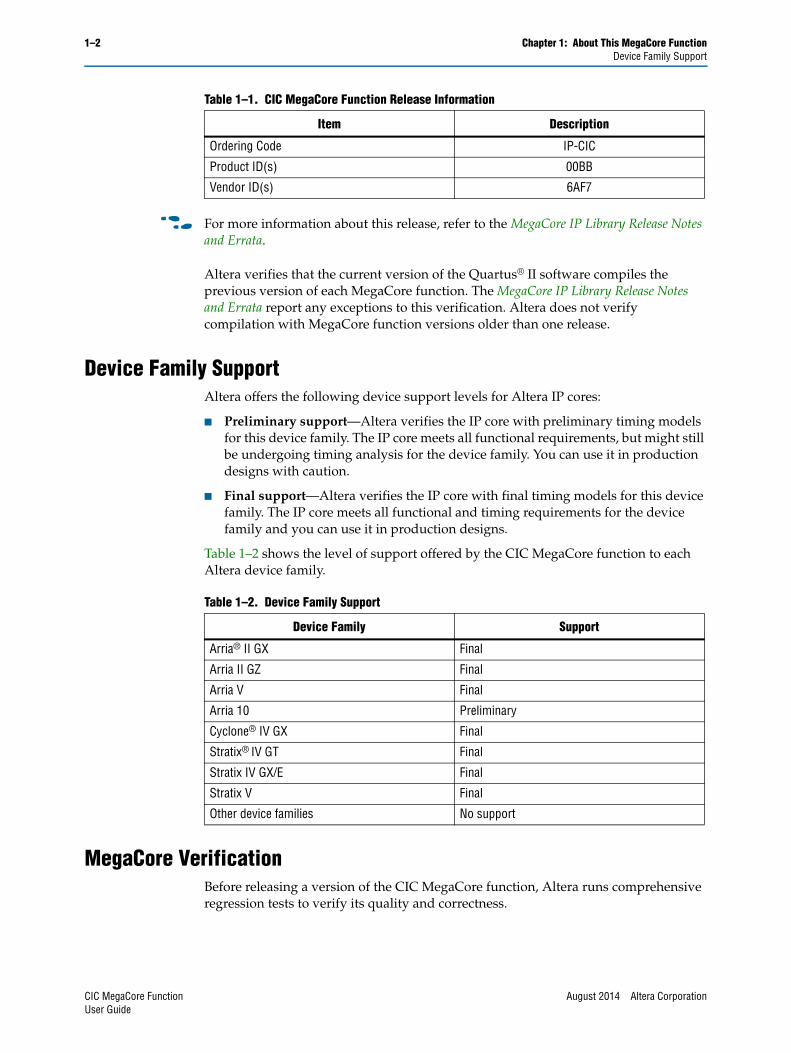
Release InformationTable 1–1 provides information about this release of the Altera CIC MegaCore function.
Table 1–1. CIC MegaCore Function Release Information
Item Description
Version 14.0 Arria 10 Edition
Release Date August 2014
CIC MegaCore FunctionUser Guide
1–2 Chapter 1: About This MegaCore FunctionDevice Family Support
f For more information about this release, refer to the MegaCore IP Library Release Notes and Errata.
Altera verifies that the current version of the Quartus® II software compiles the previous version of each MegaCore function. The MegaCore IP Library Release Notes and Errata report any exceptions to this verification. Altera does not verify compilation with MegaCore function versions older than one release.
Device Family SupportAltera offers the following device support levels for Altera IP cores:
■ Preliminary support—Altera verifies the IP core with preliminary timing models for this device family. The IP core meets all functional requirements, but might still be undergoing timing analysis for the device family. You can use it in production designs with caution.
■ Final support—Altera verifies the IP core with final timing models for this device family. The IP core meets all functional and timing requirements for the device family and you can use it in production designs.
Table 1–2 shows the level of support offered by the CIC MegaCore function to each Altera device family.
MegaCore VerificationBefore releasing a version of the CIC MegaCore function, Altera runs comprehensive regression tests to verify its quality and correctness.
Ordering Code IP-CIC
Product ID(s) 00BB
Vendor ID(s) 6AF7
Table 1–1. CIC MegaCore Function Release Information
Item Description
Table 1–2. Device Family Support
Device Family Support
Arria® II GX Final
Arria II GZ Final
Arria V Final
Arria 10 Preliminary
Cyclone® IV GX Final
Stratix® IV GT Final
Stratix IV GX/E Final
Stratix V Final
Other device families No support
CIC MegaCore Function August 2014 Altera CorporationUser Guide

Chapter 1: About This MegaCore Function 1–3Performance and Resource Utilization
Custom variations of the CIC MegaCore function are generated to exercise its various parameter options, and the resulting simulation models are thoroughly simulated with the results verified against master simulation models.
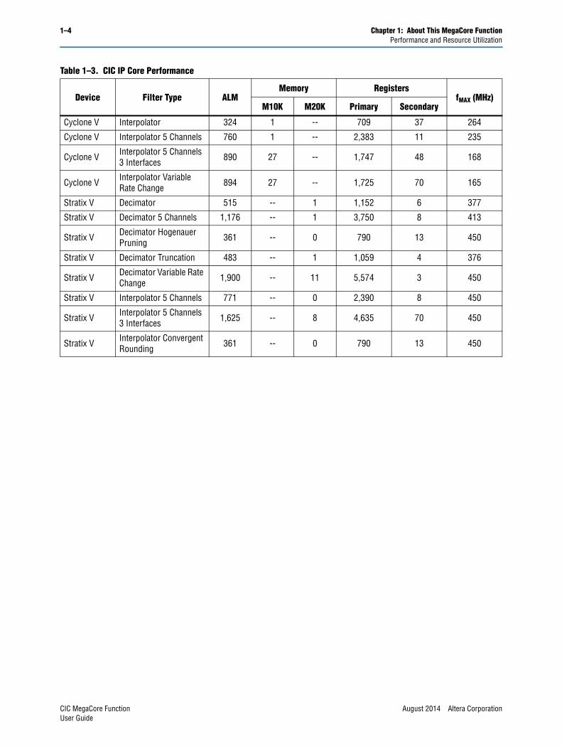
Performance and Resource UtilizationTable 1–3 shows typical expected performance for a CIC MegaCore function using the Quartus II software with the Arria V (5AGXFB3H4F40C4), Cyclone V (5CGXFC7D6F31C6), and Stratix V (5SGSMD4H2F35C2) devices:
The following parameters apply:
■ Number of stages: 8
■ Rate change factor: 8
■ Differential delay: 1
■ Integrator data storage: Memory (whenever possible)
■ Differentiator data storage: Memory (whenever possible)
■ Input data width: 16
■ Output data width: Full precision
■ Output rounding: No rounding
The target fMAX is 1 GHz.
Table 1–3. CIC IP Core Performance
Device Filter Type ALMMemory Registers
fMAX (MHz)M10K M20K Primary Secondary
Arria V Decimator 5 Channels 1,162 2 -- 3,749 6 207
Arria V Decimator 5 Channels 3 Interfaces 911 37 -- 1,722 6 255
Arria V Decimator Hogenauer Pruning 352 1 -- 785 12 304
Arria V Decimator Variable Rate Change 919 37 -- 1,730 7 256
Arria V Interpolator 326 1 -- 728 18 320
Arria V Interpolator 5 Channels 762 1 -- 2,369 27 288
Arria V Interpolator Convergent Rounding 352 1 -- 785 12 304
Arria V Interpolator Variable Rate Change 889 27 -- 1,772 23 235
Cyclone V Decimator 492 2 -- 1,137 17 182
Cyclone V Decimator 5 Channels 3 Interfaces 906 37 -- 1,719 9 204
Cyclone V Decimator Hogenauer Pruning 352 1 -- 784 14 246
Cyclone V Decimator Truncation 463 2 -- 1,054 4 177
August 2014 Altera Corporation CIC MegaCore FunctionUser Guide
1–4 Chapter 1: About This MegaCore FunctionPerformance and Resource Utilization
Cyclone V Interpolator 324 1 -- 709 37 264
Cyclone V Interpolator 5 Channels 760 1 -- 2,383 11 235
Cyclone V Interpolator 5 Channels 3 Interfaces 890 27 -- 1,747 48 168
Cyclone V Interpolator Variable Rate Change 894 27 -- 1,725 70 165
Stratix V Decimator 515 -- 1 1,152 6 377
Stratix V Decimator 5 Channels 1,176 -- 1 3,750 8 413
Stratix V Decimator Hogenauer Pruning 361 -- 0 790 13 450
Stratix V Decimator Truncation 483 -- 1 1,059 4 376
Stratix V Decimator Variable Rate Change 1,900 -- 11 5,574 3 450
Stratix V Interpolator 5 Channels 771 -- 0 2,390 8 450
Stratix V Interpolator 5 Channels 3 Interfaces 1,625 -- 8 4,635 70 450
Stratix V Interpolator Convergent Rounding 361 -- 0 790 13 450
Table 1–3. CIC IP Core Performance
Device Filter Type ALMMemory Registers
fMAX (MHz)M10K M20K Primary Secondary
CIC MegaCore Function August 2014 Altera CorporationUser Guide
August 2014 Altera Corporation
2. Getting Started
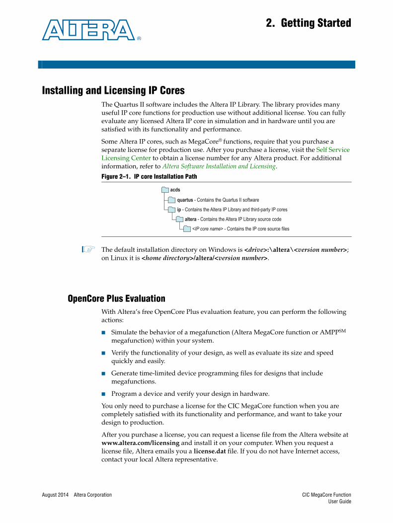
Installing and Licensing IP CoresThe Quartus II software includes the Altera IP Library. The library provides many useful IP core functions for production use without additional license. You can fully evaluate any licensed Altera IP core in simulation and in hardware until you are satisfied with its functionality and performance.
Some Altera IP cores, such as MegaCore® functions, require that you purchase a separate license for production use. After you purchase a license, visit the Self Service Licensing Center to obtain a license number for any Altera product. For additional information, refer to Altera Software Installation and Licensing.
1 The default installation directory on Windows is <drive>:\altera\<version number>; on Linux it is <home directory>/altera/<version number>.
OpenCore Plus EvaluationWith Altera’s free OpenCore Plus evaluation feature, you can perform the following actions:
■ Simulate the behavior of a megafunction (Altera MegaCore function or AMPPSM megafunction) within your system.
■ Verify the functionality of your design, as well as evaluate its size and speed quickly and easily.
■ Generate time-limited device programming files for designs that include megafunctions.
■ Program a device and verify your design in hardware.
You only need to purchase a license for the CIC MegaCore function when you are completely satisfied with its functionality and performance, and want to take your design to production.
After you purchase a license, you can request a license file from the Altera website at www.altera.com/licensing and install it on your computer. When you request a license file, Altera emails you a license.dat file. If you do not have Internet access, contact your local Altera representative.
Figure 2–1. IP core Installation Path
acds
quartus - Contains the Quartus II software
ip - Contains the Altera IP Library and third-party IP cores
altera - Contains the Altera IP Library source code
<IP core name> - Contains the IP core source files
CIC MegaCore FunctionUser Guide

2–2 Chapter 2: Getting StartedCustomizing and Generating IP Cores
f For more information about OpenCore Plus hardware evaluation, refer to AN320: OpenCore Plus Evaluation of Megafunctions.
OpenCore Plus Time-Out BehaviorOpenCore Plus hardware evaluation supports the following operation modes:
■ Untethered—the design runs for a limited time.
■ Tethered—requires a connection between your board and the host computer. If tethered mode is supported by all megafunctions in a design, the device can operate for a longer time or indefinitely.
All megafunctions in a device time-out simultaneously when the most restrictive evaluation time is reached. If there is more than one megafunction in a design, a specific megafunction’s time-out behavior might be masked by the time-out behavior of the other megafunctions.
The untethered time-out for the CIC MegaCore function is one hour; the tethered time-out value is indefinite.
The data output signal is forced to zero when the hardware evaluation time expires.
Customizing and Generating IP CoresYou can customize IP cores to support a wide variety of applications. The Quartus II IP Catalog displays IP cores available for the current target device. The parameter editor guides you to set parameter values for optional ports, features, and output files.
To customize and generate a custom IP core variation, follow these steps:
1. In the IP Catalog (Tools > IP Catalog), locate and double-click the name of the IP core to customize. The parameter editor appears.
2. Specify a top-level name for your custom IP variation. This name identifies the IP core variation files in your project. If prompted, also specify the target Altera device family and output file HDL preference. Click OK.
3. Specify the desired parameters, output, and options for your IP core variation:
■ Optionally select preset parameter values. Presets specify all initial parameter values for specific applications (where provided).
■ Specify parameters defining the IP core functionality, port configuration, and device-specific features.
■ Specify options for generation of a timing netlist, simulation model, testbench, or example design (where applicable).
■ Specify options for processing the IP core files in other EDA tools.
4. Click Finish or Generate to generate synthesis and other optional files matching your IP variation specifications. The parameter editor generates the top-level .qip or .qsys IP variation file and HDL files for synthesis and simulation. Some IP cores also simultaneously generate a testbench or example design for hardware testing.
5. To generate a simulation testbench, click Generate > Generate Testbench System. Generate > Generate Testbench System is not available for some IP cores.
CIC MegaCore Function August 2014 Altera CorporationUser Guide
Chapter 2: Getting Started 2–3Files Generated for Altera IP Cores
6. To generate a top-level HDL design example for hardware verification, click Generate > HDL Example. Generate > HDL Example is not available for some IP cores.
When you generate the IP variation with a Quartus II project open, the parameter editor automatically adds the IP variation to the project. Alternatively, click Project > Add/Remove Files in Project to manually add a top-level .qip or .qsys IP variation file to a Quartus II project. To fully integrate the IP into the design, make appropriate pin assignments to connect ports. You can define a virtual pin to avoid making specific pin assignments to top-level signals.
1 A MegaCore function report file containing a list of the design files and ports defined for your MegaCore function variation is saved as a HTML file if you turn on the MegaCore function report file check box in the MegaWizard Summary page.
For a full description of the signals supported on external ports for your MegaCore function variation, refer to Table 3–5 on page 3–12.
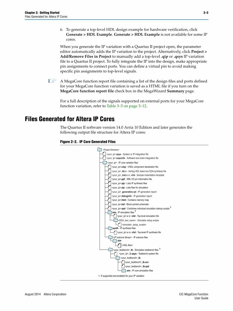
Files Generated for Altera IP CoresThe Quartus II software version 14.0 Arria 10 Edition and later generates the following output file structure for Altera IP cores:
Figure 2–2. IP Core Generated Files
<Project Directory>
<your_testbench>_tb.csv<your_testbench>_tb.spd
sim - IP core simulation files
<your_testbench>_tb - Simulation testbench files
<your_testbench>_tb
<your_ip> - IP core variation files<your_ip>.cmp - VHDL component declaration file
<your_ip>.ppf - XML I/O pin information file<your_ip>.qip - Lists IP synthesis files<your_ip>.sip - Lists files for simulation
synth - IP synthesis files<your_ip>.v or .vhd - Top-level IP synthesis file
sim - IP simulation files 1
<your_ip>.v or .vhd - Top-level simulation file<EDA_tool_name> - Simulator setup scripts
<simulator_setup_scripts>
<IP subcore library> - IP subcore files
<HDL files>
sim
<your_ip>.qsys - System or IP integration file
<your_ip>_bb.v - Verilog HDL black box EDA synthesis file<your_ip>_inst.v or .vhd - Sample instantiation template
<your_ip>_generation.rpt - IP generation report<your_ip>.debuginfo - IP generation report<your_ip>.html - Contains memory map<your_ip>.bsf - Block symbol schematic<your_ip>.spd - Combines individual simulation startup scripts 1
<your_ip>_tb.qsys - Testbench system file
1
<your_ip>.sopcinfo - Software tool-chain integration file
1. If supported and enabled for your IP variation
August 2014 Altera Corporation CIC MegaCore FunctionUser Guide

2–4 Chapter 2: Getting StartedSimulating IP Cores
Simulating IP CoresThe Quartus II software supports RTL- and gate-level design simulation of Altera IP cores in supported EDA simulators. Simulation involves setting up your simulator working environment, compiling simulation model libraries, and running your simulation.
You can use the functional simulation model and the testbench or example design generated with your IP core for simulation. The functional simulation model and testbench files are generated in a project subdirectory. This directory may also include scripts to compile and run the testbench. For a complete list of models or libraries required to simulate your IP core, refer to the scripts generated with the testbench. You can use the Quartus II NativeLink feature to automatically generate simulation files and scripts. NativeLink launches your preferred simulator from within the Quartus II software.
For more information about simulating Altera IP cores, refer to Simulating Altera Designs in volume 3 of the Quartus II Handbook.
Including Other IP Libraries and FilesThe Quartus II software searches for IP cores in the project directory, in the Altera installation directory, and in the defined IP search path. You can include IP libraries and files from other locations by modifying the IP search path. To use the GUI to modify the global or project-specific search path, click Tools > Options > IP Search Locations and specify the path to your IP.
As an alternative to the GUI, use the following SEARCH_PATH assignment to include one or more project libraries. Specify only one source directory for each SEARCH_PATH assignment.
set_global_assignment -name SEARCH_PATH <library or file path>
Figure 2–3. Specifying IP Search Locations
Adds new global IP search paths
Changes search path order
Adds new project-specific IP search paths
Lists current project and global search paths
CIC MegaCore Function August 2014 Altera CorporationUser Guide

Chapter 2: Getting Started 2–5Upgrading Outdated IP Cores
If your project includes two IP core files of the same name, the following search path precedence rules determine the resolution of files:
1. Project directory files.
2. Project database directory files.
3. Project libraries specified in IP Search Locations, or with the SEARCH_PATH assignment in the Quartus II Settings File (.qsf).
4. Global libraries specified in IP Search Locations, or with the SEARCH_PATH assignment in the Quartus II Settings File (.qsf).
5. Quartus II software libraries directory, such as <Quartus II Installation>\libraries.
Upgrading Outdated IP CoresIP cores generated with a previous version of the Quartus II software may require upgrade before use in the current version of the Quartus II software. Click Project > Upgrade IP Components to identify and upgrade outdated IP cores.
The Upgrade IP Components dialog box provides instructions when IP upgrade is required, optional, or unsupported for specific IP cores in your design. Most Altera IP cores support one-click, automatic simultaneous upgrade. You can individually migrate IP cores unsupported by auto-upgrade.
The Upgrade IP Components dialog box also reports legacy Altera IP cores that support compilation-only (without modification), as well as IP cores that do not support migration. Replace unsupported IP cores in your project with an equivalent Altera IP core or design logic.Upgrading IP cores changes your original design files.
Before you begin
■ Migrate your Quartus II project containing outdated IP cores to the latest version of the Quartus II software. In a previous version of the Quartus II software, click Project > Archive Project to save the project. This archive preserves your original design source and project files after migration. le paths in the archive must be relative to the project directory. File paths in the archive must reference the IP variation .v or .vhd file or .qsys file, not the .qip file.
■ Restore the project in the latest version of the Quartus II software. Click Project > Restore Archived Project. Click Ok if prompted to change to a supported device or overwrite the project database.
To upgrade outdated IP cores, follow these steps:
1. In the latest version of the Quartus II software, open the Quartus II project containing an outdated IP core variation.
1 File paths in a restored project archive must be relative to the project directory and you must reference the IP variation .v or .vhd file or .qsys file, not the .qip file.
2. Click Project > Upgrade IP Components. The Upgrade IP Components dialog box displays all outdated IP cores in your project, along with basic instructions for upgrading each core.
August 2014 Altera Corporation CIC MegaCore FunctionUser Guide
2–6 Chapter 2: Getting StartedDSP Builder Design Flow
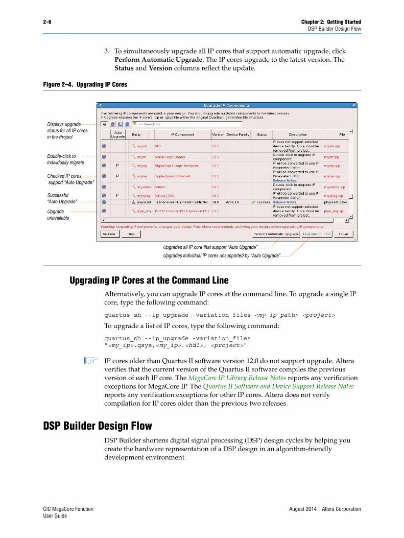
3. To simultaneously upgrade all IP cores that support automatic upgrade, click Perform Automatic Upgrade. The IP cores upgrade to the latest version. The Status and Version columns reflect the update.
Upgrading IP Cores at the Command LineAlternatively, you can upgrade IP cores at the command line. To upgrade a single IP core, type the following command:
quartus_sh --ip_upgrade -variation_files <my_ip_path> <project>
To upgrade a list of IP cores, type the following command:
quartus_sh --ip_upgrade -variation_files"<my_ip>.qsys;<my_ip>.<hdl>; <project>"
1 IP cores older than Quartus II software version 12.0 do not support upgrade. Altera verifies that the current version of the Quartus II software compiles the previous version of each IP core. The MegaCore IP Library Release Notes reports any verification exceptions for MegaCore IP. The Quartus II Software and Device Support Release Notes reports any verification exceptions for other IP cores. Altera does not verify compilation for IP cores older than the previous two releases.
DSP Builder Design FlowDSP Builder shortens digital signal processing (DSP) design cycles by helping you create the hardware representation of a DSP design in an algorithm-friendly development environment.
Figure 2–4. Upgrading IP Cores
Displays upgradestatus for all IP coresin the Project
Upgrades all IP core that support “Auto Upgrade”Upgrades individual IP cores unsupported by “Auto Upgrade”
Checked IP coressupport “Auto Upgrade”
Successful“Auto Upgrade”
Upgradeunavailable
Double-click toindividually migrate
CIC MegaCore Function August 2014 Altera CorporationUser Guide

Chapter 2: Getting Started 2–7DSP Builder Design Flow
This IP core supports DSP Builder. Use the DSP Builder flow if you want to create a DSP Builder model that includes an IP core variation; use IP Catalog if you want to create an IP core variation that you can instantiate manually in your design.
f For more information about the DSP Builder flow, refer to the Using MegaCore Functions chapter in the DSP Builder Handbook.
August 2014 Altera Corporation CIC MegaCore FunctionUser Guide

2–8 Chapter 2: Getting StartedDSP Builder Design Flow
CIC MegaCore Function August 2014 Altera CorporationUser Guide

August 2014 Altera Corporation
3. Functional Description
You can select either a decimation or interpolation CIC filter. A decimation CIC filter comprises a cascade of integrators (integrator), followed by a down sampling block (decimator) and a cascade of differentiators (called the differentiator or comb section). Similarly an interpolation CIC filter comprises a cascade of differentiators, followed by an up sampling block (interpolator) and a cascade of integrators.
In a CIC filter, both the integrator and comb sections have the same number of integrators and differentiators. Each pairing of integrator and differentiator is a stage. The number of stages (N) has a direct effect on the frequency response of a CIC filter. You determine the response of the filter by configuring:
■ The number of stages N
■ The rate change factor R
■ The number of delays in the differentiators (differential delay) M. Generally, set the differential delay to 1 or 2.
Figure 3–1 shows the frequency response for a CIC decimation filter with N = 3, M = 2 and R = 32.
Variable Rate Change FactorsYou can optionally set minimum and maximum values for the decimator or interpolator rate change factors and enable the rate change factors to be set at run time. With these options, the CIC provides an additional rate port that you can use to specify the rate change factor.
Figure 3–1. Three stage CIC Decimation Filter Frequency Response
CIC MegaCore FunctionUser Guide
3–2 Chapter 3: Functional DescriptionMultichannel Support
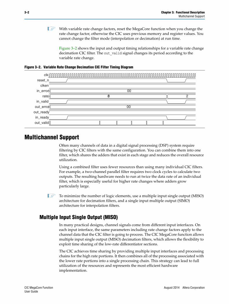
1 With variable rate change factors, reset the MegaCore function when you change the rate change factor, otherwise the CIC uses previous memory and register values. You cannot change the filter mode (interpolation or decimation) at run time.
Figure 3–2 shows the input and output timing relationships for a variable rate change decimation CIC filter. The out_valid signal changes its period according to the variable rate change.
Multichannel SupportOften many channels of data in a digital signal processing (DSP) system require filtering by CIC filters with the same configuration. You can combine them into one filter, which shares the adders that exist in each stage and reduces the overall resource utilization.
Using a combined filter uses fewer resources than using many individual CIC filters. For example, a two-channel parallel filter requires two clock cycles to calculate two outputs. The resulting hardware needs to run at twice the data rate of an individual filter, which is especially useful for higher rate changes where adders grow particularly large.
1 To minimize the number of logic elements, use a multiple input single output (MISO) architecture for decimation filters, and a single input multiple output (SIMO) architecture for interpolation filters.
Multiple Input Single Output (MISO)In many practical designs, channel signals come from different input interfaces. On each input interface, the same parameters including rate change factors apply to the channel data that the CIC filter is going to process. The CIC MegaCore function allows multiple input single output (MISO) decimation filters, which allows the flexibility to exploit time sharing of the low-rate differentiator sections.
The CIC achieves time sharing by providing multiple input interfaces and processing chains for the high rate portions. It then combines all of the processing associated with the lower rate portions into a single processing chain. This strategy can lead to full utilization of the resources and represents the most efficient hardware implementation.
Figure 3–2. Variable Rate Change Decimation CIC Filter Timing Diagram
clk
reset_n
clken
in_error
rate
in_valid
out_error
out_ready
in_ready
out_valid
00
8 28
00
CIC MegaCore Function August 2014 Altera CorporationUser Guide
Chapter 3: Functional Description 3–3Multichannel Support
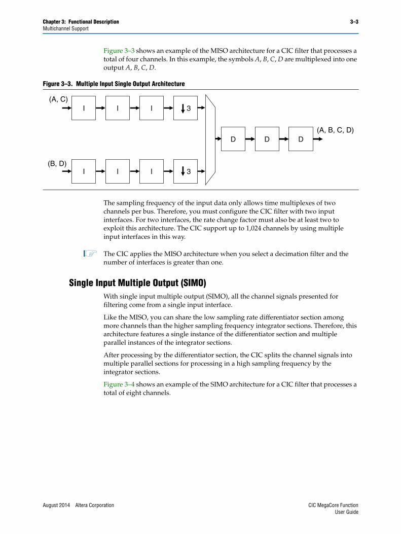
Figure 3–3 shows an example of the MISO architecture for a CIC filter that processes a total of four channels. In this example, the symbols A, B, C, D are multiplexed into one output A, B, C, D.
The sampling frequency of the input data only allows time multiplexes of two channels per bus. Therefore, you must configure the CIC filter with two input interfaces. For two interfaces, the rate change factor must also be at least two to exploit this architecture. The CIC support up to 1,024 channels by using multiple input interfaces in this way.
1 The CIC applies the MISO architecture when you select a decimation filter and the number of interfaces is greater than one.
Single Input Multiple Output (SIMO)With single input multiple output (SIMO), all the channel signals presented for filtering come from a single input interface.
Like the MISO, you can share the low sampling rate differentiator section among more channels than the higher sampling frequency integrator sections. Therefore, this architecture features a single instance of the differentiator section and multiple parallel instances of the integrator sections.
After processing by the differentiator section, the CIC splits the channel signals into multiple parallel sections for processing in a high sampling frequency by the integrator sections.
Figure 3–4 shows an example of the SIMO architecture for a CIC filter that processes a total of eight channels.
Figure 3–3. Multiple Input Single Output Architecture
D D D
(A, C)
(B, D)
(A, B, C, D)
3
3
I I I
I I I
D D D
August 2014 Altera Corporation CIC MegaCore FunctionUser Guide

3–4 Chapter 3: Functional DescriptionOutput Options
In this example, the symbols A, B, C, D, E, F, G, H are demultiplexed into four outputs A, E; B, F; C, G; and D, H.
The required sampling frequency of the output data only allows time multiplexes of two channels per bus. Therefore, you must configure the CIC filter with four output interfaces. The rate change factor must also be at least four to exploit this architecture, but this example shows a rate change of eight.
1 The CIC applies a SIMO when you select an interpolation filter and the number of interfaces is greater than one.
The total number of input channels must be a multiple of the number of interfaces. To satisfy this requirement, you may need to either insert dummy channels or use more than one CIC MegaCore function.
The CIC transfers data as packets using Avalon Streaming (Avalon-ST) interfaces (“Avalon-ST Interface” on page 3–9).
f For an example design using multichannel MISO and SIMO architectures, refer to AN442: Tool Flow Design of Digital IF for Wireless Systems.
Output OptionsYou can select output options for the output data bit width and rounding options.
Output Data WidthFor a decimation filter, the gain at the output of the filter is:
Figure 3–4. Single Input Multiple Output Architecture
I I I
I I I
I I I
I I I
(A,B,C,D,E,F,G,H)
(A,E)
(B,F)
(C,G)
(D,H)
D D D
I I I
I I I
I I I
I I I
8
8
8
8
G RM N=
CIC MegaCore Function August 2014 Altera CorporationUser Guide
Chapter 3: Functional Description 3–5Output Options
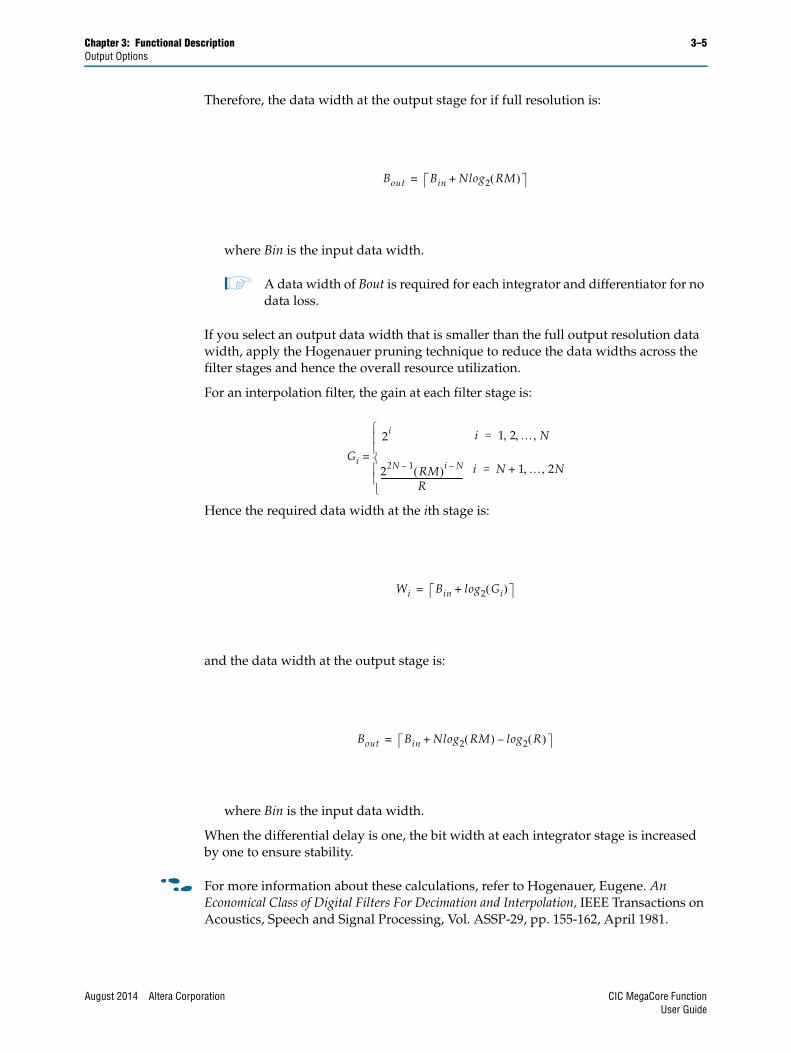
Therefore, the data width at the output stage for if full resolution is:
where Bin is the input data width.
1 A data width of Bout is required for each integrator and differentiator for no data loss.
If you select an output data width that is smaller than the full output resolution data width, apply the Hogenauer pruning technique to reduce the data widths across the filter stages and hence the overall resource utilization.
For an interpolation filter, the gain at each filter stage is:
Hence the required data width at the ith stage is:
and the data width at the output stage is:
where Bin is the input data width.
When the differential delay is one, the bit width at each integrator stage is increased by one to ensure stability.
f For more information about these calculations, refer to Hogenauer, Eugene. An Economical Class of Digital Filters For Decimation and Interpolation, IEEE Transactions on Acoustics, Speech and Signal Processing, Vol. ASSP-29, pp. 155-162, April 1981.
Bout Bin Nlog2 RM +=
Gi
2i
22N 1– RM i N–
R-----------------------------------------
=
i 1 2 N =
i N 1 2N +=
Wi Bin log2 Gi +=
Bout Bin Nlog2 RM log2 R –+=
August 2014 Altera Corporation CIC MegaCore FunctionUser Guide
3–6 Chapter 3: Functional DescriptionFIR Filter Compensation Coefficients
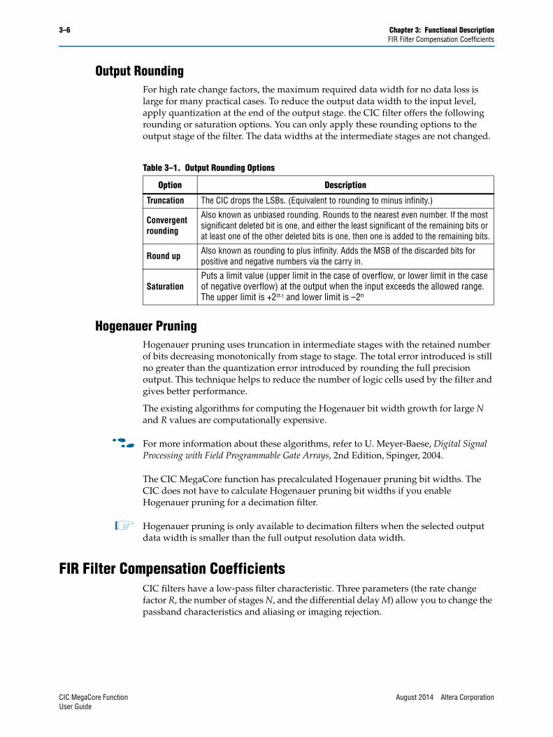
Output RoundingFor high rate change factors, the maximum required data width for no data loss is large for many practical cases. To reduce the output data width to the input level, apply quantization at the end of the output stage. the CIC filter offers the following rounding or saturation options. You can only apply these rounding options to the output stage of the filter. The data widths at the intermediate stages are not changed.
Hogenauer PruningHogenauer pruning uses truncation in intermediate stages with the retained number of bits decreasing monotonically from stage to stage. The total error introduced is still no greater than the quantization error introduced by rounding the full precision output. This technique helps to reduce the number of logic cells used by the filter and gives better performance.
The existing algorithms for computing the Hogenauer bit width growth for large N and R values are computationally expensive.
f For more information about these algorithms, refer to U. Meyer-Baese, Digital Signal Processing with Field Programmable Gate Arrays, 2nd Edition, Spinger, 2004.
The CIC MegaCore function has precalculated Hogenauer pruning bit widths. The CIC does not have to calculate Hogenauer pruning bit widths if you enable Hogenauer pruning for a decimation filter.
1 Hogenauer pruning is only available to decimation filters when the selected output data width is smaller than the full output resolution data width.
FIR Filter Compensation CoefficientsCIC filters have a low-pass filter characteristic. Three parameters (the rate change factor R, the number of stages N, and the differential delay M) allow you to change the passband characteristics and aliasing or imaging rejection.
Table 3–1. Output Rounding Options
Option Description
Truncation The CIC drops the LSBs. (Equivalent to rounding to minus infinity.)
Convergent rounding
Also known as unbiased rounding. Rounds to the nearest even number. If the most significant deleted bit is one, and either the least significant of the remaining bits or at least one of the other deleted bits is one, then one is added to the remaining bits.
Round up Also known as rounding to plus infinity. Adds the MSB of the discarded bits for positive and negative numbers via the carry in.
SaturationPuts a limit value (upper limit in the case of overflow, or lower limit in the case of negative overflow) at the output when the input exceeds the allowed range. The upper limit is +2n-1 and lower limit is –2n
CIC MegaCore Function August 2014 Altera CorporationUser Guide
Chapter 3: Functional Description 3–7FIR Filter Compensation Coefficients
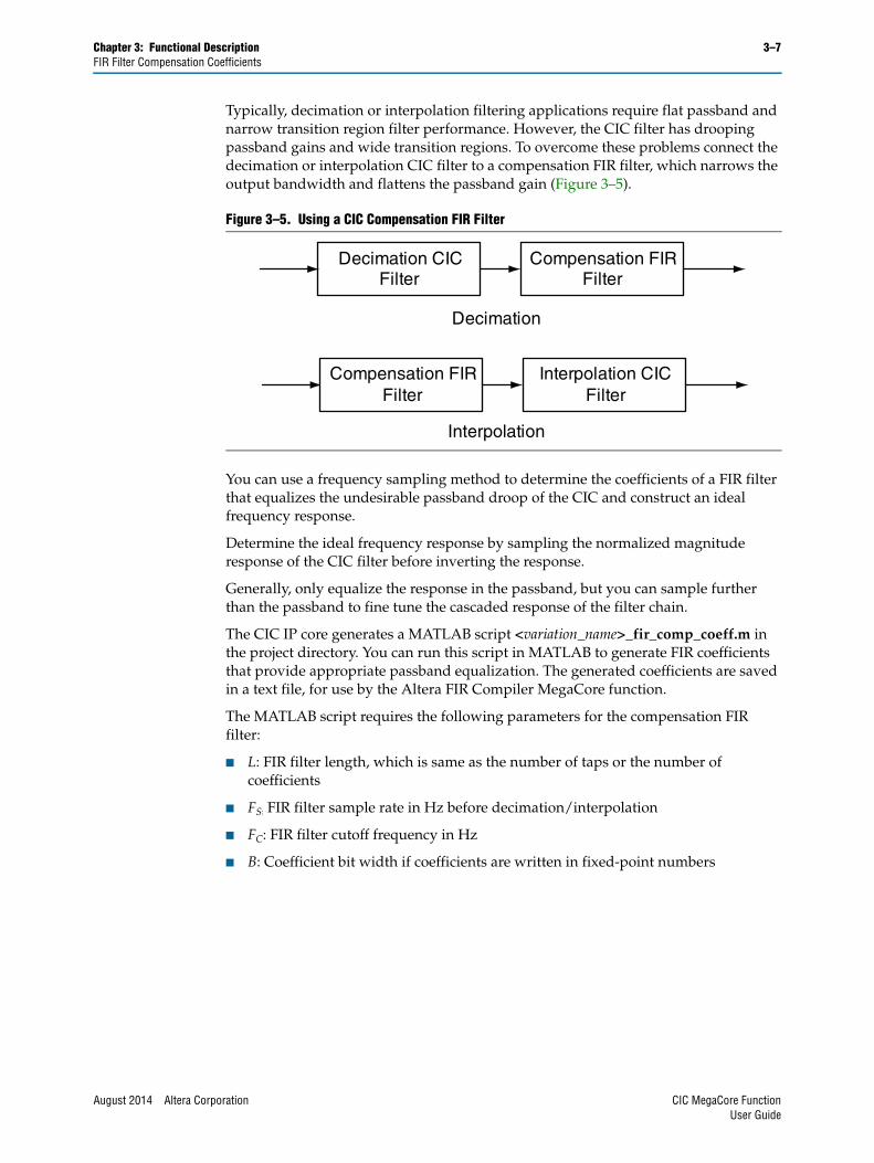
Typically, decimation or interpolation filtering applications require flat passband and narrow transition region filter performance. However, the CIC filter has drooping passband gains and wide transition regions. To overcome these problems connect the decimation or interpolation CIC filter to a compensation FIR filter, which narrows the output bandwidth and flattens the passband gain (Figure 3–5).
You can use a frequency sampling method to determine the coefficients of a FIR filter that equalizes the undesirable passband droop of the CIC and construct an ideal frequency response.
Determine the ideal frequency response by sampling the normalized magnitude response of the CIC filter before inverting the response.
Generally, only equalize the response in the passband, but you can sample further than the passband to fine tune the cascaded response of the filter chain.
The CIC IP core generates a MATLAB script <variation_name>_fir_comp_coeff.m in the project directory. You can run this script in MATLAB to generate FIR coefficients that provide appropriate passband equalization. The generated coefficients are saved in a text file, for use by the Altera FIR Compiler MegaCore function.
The MATLAB script requires the following parameters for the compensation FIR filter:
■ L: FIR filter length, which is same as the number of taps or the number of coefficients
■ FS: FIR filter sample rate in Hz before decimation/interpolation
■ FC: FIR filter cutoff frequency in Hz
■ B: Coefficient bit width if coefficients are written in fixed-point numbers
Figure 3–5. Using a CIC Compensation FIR Filter
Decimation CIC Filter
Compensation FIR Filter
Compensation FIR Filter
Interpolation CIC Filter
Decimation
Interpolation
August 2014 Altera Corporation CIC MegaCore FunctionUser Guide
3–8 Chapter 3: Functional DescriptionParameters
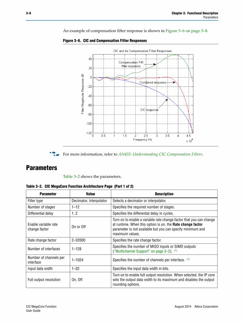
An example of compensation filter response is shown in Figure 3–6 on page 3–8.
f For more information, refer to AN455: Understanding CIC Compensation Filters.
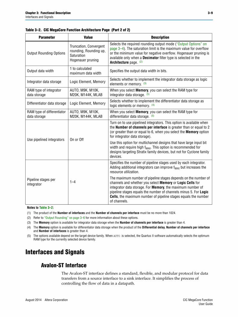
ParametersTable 3–2 shows the parameters.
Figure 3–6. CIC and Compensation Filter Responses
Table 3–2. CIC MegaCore Function Architecture Page (Part 1 of 2)
Parameter Value Description
Filter type Decimator, Interpolator Selects a decimator or interpolator.
Number of stages 1–12 Specifies the required number of stages.
Differential delay 1, 2 Specifies the differential delay in cycles.
Enable variable rate change factor On or Off
Turn on to enable a variable rate change factor that you can change at runtime. When this option is on, the Rate change factor parameter is not available but you can specify minimum and maximum values.
Rate change factor 2–32000 Specifies the rate change factor.
Number of interfaces 1–128 Specifies the number of MISO inputs or SIMO outputs (“Multichannel Support” on page 3–2). (1)
Number of channels per interface 1–1024 Specifies the number of channels per interface. (1)
Input data width 1–32 Specifies the input data width in bits.
Full output resolution On, OffTurn on to enable full output resolution. When selected, the IP core sets the output data width to its maximum and disables the output rounding options.
CIC MegaCore Function August 2014 Altera CorporationUser Guide
Chapter 3: Functional Description 3–9Interfaces and Signals
Interfaces and Signals
Avalon-ST InterfaceThe Avalon-ST interface defines a standard, flexible, and modular protocol for data transfers from a source interface to a sink interface. It simplifies the process of controlling the flow of data in a datapath.
Output Rounding Options
Truncation, Convergent rounding, Rounding up, SaturationHogenauer pruning
Selects the required rounding output mode (“Output Options” on page 3–4). The saturation limit is the maximum value for overflow or the minimum value for negative overflow. Hogenauer pruning is available only when a Decimator filter type is selected in the Architecture page. (2)
Output data width 1 to calculated maximum data width Specifies the output data width in bits.
Integrator data storage Logic Element, Memory Selects whether to implement the integrator data storage as logic elements or memory. (3)
RAM type of integrator data storage
AUTO, M9K, M10K, M20K, M144K, MLAB
When you select Memory, you can select the RAM type for integrator data storage. (5)
Differentiator data storage Logic Element, Memory Selects whether to implement the differentiator data storage as logic elements or memory. (4)
RAM type of differentiator data storage
AUTO, M9K, M10K, M20K, M144K, MLAB
When you select Memory, you can select the RAM type for differentiator data storage. (5)
Use pipelined integrators On or Off
Turn on to use pipelined integrators. This option is available when the Number of channels per interface is greater than or equal to 2 (or greater than or equal to 6, when you select the Memory option for integrator data storage).
Use this option for multichannel designs that have large input bit width and require high fMAX. This option is recommended for designs targeting Stratix family devices, but not for Cyclone family devices.
Pipeline stages per integrator 1–4
Specifies the number of pipeline stages used by each integrator. Adding additional integrators can improve fMAX but increases the resource utilization.
The maximum number of pipeline stages depends on the number of channels and whether you select Memory or Logic Cells for integrator data storage. For Memory, the maximum number of pipeline stages equals the number of channels minus 5. For Logic Cells, the maximum number of pipeline stages equals the number of channels.
Notes to Table 3–2:
(1) The product of the Number of interfaces and the Number of channels per interface must be no more than 1024.(2) Refer to “Output Rounding” on page 3–6 for more information about these options.(3) The Memory option is available for integrator data storage when the Number of channels per interface is greater than 4. (4) The Memory option is available for differentiator data storage when the product of the Differential delay, Number of channels per interface
and Number of interfaces is greater than 4.(5) The options available depend on the target device family. When AUTO is selected, the Quartus II software automatically selects the optimum
RAM type for the currently selected device family.
Table 3–2. CIC MegaCore Function Architecture Page (Part 2 of 2)
Parameter Value Description
August 2014 Altera Corporation CIC MegaCore FunctionUser Guide
3–10 Chapter 3: Functional DescriptionInterfaces and Signals
Avalon-ST interface signals can describe traditional streaming interfaces supporting a single stream of data without knowledge of channels or packet boundaries. Such interfaces typically contain data, ready, and valid signals.
The Avalon-ST interface can also support more complex protocols for burst and packet transfers with packets interleaved across multiple channels.
The Avalon-ST interface inherently synchronizes multichannel designs, which allows you to achieve efficient, time-multiplexed implementations without having to implement complex control logic.
The Avalon-ST interface supports backpressure, which is a flow control mechanism where a sink can signal to a source to stop sending data. The sink typically uses backpressure to stop the flow of data when its FIFO buffers are full or when it has congestion on its output.
When designing a datapath which includes the CIC MegaCore function, you may not need backpressure if you know that the downstream components can always receive data.
f For more information about the Avalon-ST interface, refer to the Avalon Interface Specifications.
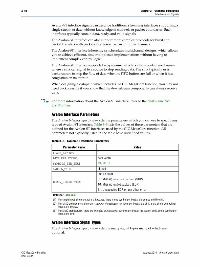
Avalon Interface ParametersThe Avalon Interface Specifications define parameters which you can use to specify any type of Avalon-ST interface. Table 3–3 lists the values of these parameters that are defined for the Avalon-ST interfaces used by the CIC MegaCore function. All parameters not explicitly listed in the table have undefined values.
Avalon Interface Signal TypesThe Avalon Interface Specifications define many signal types many of which are optional.
Table 3–3. Avalon-ST Interface Parameters
Parameter Name Value
READY_LATENCY 0
BITS_PER_SYMBOL data width
SYMBOLS_PER_BEAT (1), (2), (3)
SYMBOL_TYPE signed
ERROR_DESCRIPTION
00: No error
01: Missing startofpacket (SOP)
10: Missing endofpacket (EOP)
11: Unexpected EOP or any other error
Notes for Table 3–3:
(1) For single input, single output architectures, there is one symbol per beat at the source and the sink. (2) For MISO architectures, there are <number of interfaces> symbols per beat at the sink, and a single symbol per
beat at the source.(3) For SIMO architectures, there are <number of interfaces> symbols per beat at the source, and a single symbol per
beat at the sink.
CIC MegaCore Function August 2014 Altera CorporationUser Guide

Chapter 3: Functional Description 3–11Interfaces and Signals
Table 3–4 lists the signal types used by the Avalon-ST interfaces for the CIC MegaCore function.
Any signal type not explicitly listed in the table is not used by the CIC MegaCore function
f For a full description of the Avalon-ST interface protocol, refer to the Avalon Interface Specifications.
Avalon-ST Interface Data Transfer Timing Figure 3–7 shows the data transfer timing.
The source provides data and asserts valid on cycle 1, even though the sink is not ready. The source waits until cycle 2, when the sink does assert ready, before moving onto the next data cycle. In cycle 3, the source drives data on the same cycle and because the sink is ready to receive it, the transfer occurs immediately. In cycle 4, the sink asserts ready, but the source does not drive valid data.
Packet Data TransfersA beat is the transfer of one unit of data between a source and sink interface. This unit of data may consist of one or more symbols and makes it is possible to support modules that convey more than one piece of information about each valid cycle.
Packet data transfers are used for multichannel transfers. Two additional signals (startofpacket and endofpacket) are defined to implement the packet transfer.
Table 3–4. Avalon-ST Interface Signal Types
Signal Type Width
ready 1
valid 1
data data width
channel log2(number of channels)
error 2
startofpacket 1
endofpacket 1
Figure 3–7. Avalon-ST Interface Timing with READY_LATENCY=0
Do D1 D2
0 1 2 3 5 6 7 84
clk
ready
valid
error
data
00 00 00 00
D2
August 2014 Altera Corporation CIC MegaCore FunctionUser Guide
3–12 Chapter 3: Functional DescriptionInterfaces and Signals
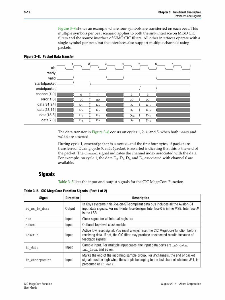
Figure 3–8 shows an example where four symbols are transferred on each beat. This multiple symbols per beat scenario applies to both the sink interface on MISO CIC filters and the source interface of SIMO CIC filters. All other interfaces operate with a single symbol per beat, but the interfaces also support multiple channels using packets.
The data transfer in Figure 3–8 occurs on cycles 1, 2, 4, and 5, when both ready and valid are asserted.
During cycle 1, startofpacket is asserted, and the first four bytes of packet are transferred. During cycle 5, endofpacket is asserted indicating that this is the end of the packet. The channel signal indicates the channel index associated with the data. For example, on cycle 1, the data D0, D1, D2, and D3 associated with channel 0 are available.
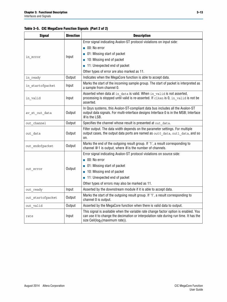
SignalsTable 3–5 lists the input and output signals for the CIC MegaCore Function.
Figure 3–8. Packet Data Transfer
0 1 2 3
00 00 00 00
D0 D4 D8 D12
D1 D5 D9 D13
D2 D6 D10 D14
D3 D7 D11 D15
1 2 3 4 5 6 7
clkreadyvalid
startofpacketendofpacketchannel[1:0]
data[31:24]data[23:16]data[15:8]data[7:0]
error[1:0]
Table 3–5. CIC MegaCore Function Signals (Part 1 of 2)
Signal Direction Description
av_st_in_data OutputIn Qsys systems, this Avalon-ST-compliant data bus includes all the Avalon-ST input data signals. For multi-interface designs Interface 0 is in the MSB; Interface N is the LSB.
clk Input Clock signal for all internal registers.
clken Input Optional top-level clock enable.
reset_n InputActive low reset signal. You must always reset the CIC MegaCore function before receiving data. If not, the CIC filter may produce unexpected results because of feedback signals.
in_data Input Sample input. For multiple input cases, the input data ports are in0_data, in1_data, and so on.
in_endofpacket InputMarks the end of the incoming sample group. For N channels, the end of packet signal must be high when the sample belonging to the last channel, channel N-1, is presented at in_data.
CIC MegaCore Function August 2014 Altera CorporationUser Guide
Chapter 3: Functional Description 3–13Interfaces and Signals
in_error Input
Error signal indicating Avalon-ST protocol violations on input side:
■ 00: No error
■ 01: Missing start of packet
■ 10: Missing end of packet
■ 11: Unexpected end of packet
Other types of error are also marked as 11.
in_ready Output Indicates when the MegaCore function is able to accept data.
in_startofpacket Input Marks the start of the incoming sample group. The start of packet is interpreted as a sample from channel 0.
in_valid InputAsserted when data at in_data is valid. When in_valid is not asserted, processing is stopped until valid is re-asserted. If clken is 0, in_valid is not be asserted.
av_st_out_data OutputIn Qsys systems, this Avalon-ST-compliant data bus includes all the Avalon-ST output data signals. For multi-interface designs Interface 0 is in the MSB; Interface N is the LSB.
out_channel Output Specifies the channel whose result is presented at out_data.
out_data OutputFilter output. The data width depends on the parameter settings. For multiple output cases, the output data ports are named as out0_data, out1_data, and so on.
out_endofpacket Output Marks the end of the outgoing result group. If '1', a result corresponding to channel N-1 is output, where N is the number of channels.
out_error Output
Error signal indicating Avalon-ST protocol violations on source side:
■ 00: No error
■ 01: Missing start of packet
■ 10: Missing end of packet
■ 11: Unexpected end of packet
Other types of errors may also be marked as 11.
out_ready Input Asserted by the downstream module if it is able to accept data.
out_startofpacket Output Marks the start of the outgoing result group. If '1', a result corresponding to channel 0 is output.
out_valid Output Asserted by the MegaCore function when there is valid data to output.
rate InputThis signal is available when the variable rate change factor option is enabled. You can use it to change the decimation or interpolation rate during run time. It has the size Ceil(log2(maximum rate)).
Table 3–5. CIC MegaCore Function Signals (Part 2 of 2)
Signal Direction Description
August 2014 Altera Corporation CIC MegaCore FunctionUser Guide

3–14 Chapter 3: Functional DescriptionInterfaces and Signals
CIC MegaCore Function August 2014 Altera CorporationUser Guide
August 2014 Altera Corporation
Additional Information
This chapter provides additional information about the document and Altera.
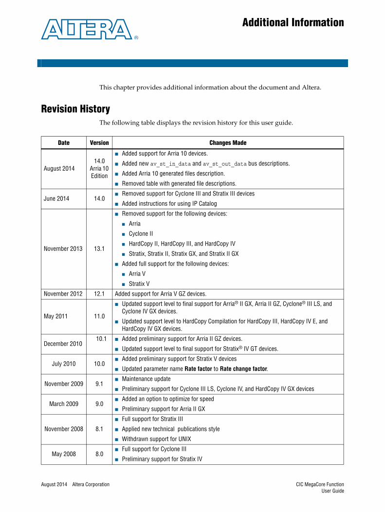
Revision History The following table displays the revision history for this user guide.
Date Version Changes Made
August 201414.0
Arria 10 Edition
■ Added support for Arria 10 devices.
■ Added new av_st_in_data and av_st_out_data bus descriptions.
■ Added Arria 10 generated files description.
■ Removed table with generated file descriptions.
June 2014 14.0■ Removed support for Cyclone III and Stratix III devices
■ Added instructions for using IP Catalog
November 2013 13.1
■ Removed support for the following devices:
■ Arria
■ Cyclone II
■ HardCopy II, HardCopy III, and HardCopy IV
■ Stratix, Stratix II, Stratix GX, and Stratix II GX
■ Added full support for the following devices:
■ Arria V
■ Stratix V
November 2012 12.1 Added support for Arria V GZ devices.
May 2011 11.0
■ Updated support level to final support for Arria® II GX, Arria II GZ, Cyclone® III LS, and Cyclone IV GX devices.
■ Updated support level to HardCopy Compilation for HardCopy III, HardCopy IV E, and HardCopy IV GX devices.
December 201010.1 ■ Added preliminary support for Arria II GZ devices.
■ Updated support level to final support for Stratix® IV GT devices.
July 2010 10.0■ Added preliminary support for Stratix V devices
■ Updated parameter name Rate factor to Rate change factor.
November 2009 9.1■ Maintenance update
■ Preliminary support for Cyclone III LS, Cyclone IV, and HardCopy IV GX devices
March 2009 9.0■ Added an option to optimize for speed
■ Preliminary support for Arria II GX
November 2008 8.1
■ Full support for Stratix III
■ Applied new technical publications style
■ Withdrawn support for UNIX
May 2008 8.0■ Full support for Cyclone III
■ Preliminary support for Stratix IV
CIC MegaCore FunctionUser Guide

Info–2 Additional InformationHow to Contact Altera
How to Contact AlteraTo locate the most up-to-date information about Altera products, refer to the following table.
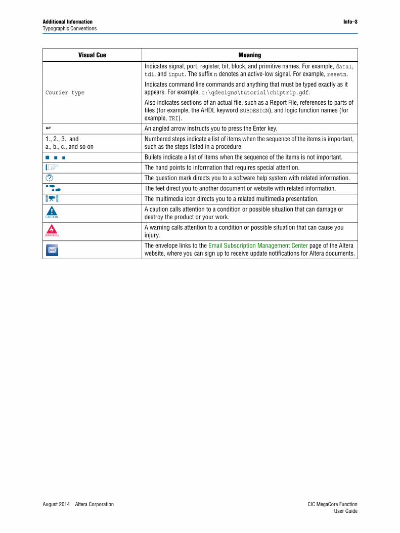
Typographic ConventionsThe following table shows the typographic conventions this document uses.
October 2007 7.2 ■ Full support for Arria GX
May 2007 7.1
■ Added description of new features for variable interpolation/decimation rate and compensation filter coefficients generation
■ Preliminary support for Arria™ GX
■ Full support for Stratix II GX and HardCopy® II devices
December 2006 7.0 ■ Preliminary support for Cyclone III
December 2006 6.1 ■ First release of this user guide
Date Version Changes Made
Contact (1) Contact Method Address
Technical support Website www.altera.com/support
Technical trainingWebsite www.altera.com/training
Email [email protected]
Product literature Website www.altera.com/literature
Nontechnical support (general) Email [email protected]
(software licensing) Email [email protected]
Note to Table:
(1) You can also contact your local Altera sales office or sales representative.
Visual Cue Meaning
Bold Type with Initial Capital Letters
Indicate command names, dialog box titles, dialog box options, and other GUI labels. For example, Save As dialog box. For GUI elements, capitalization matches the GUI.
bold typeIndicates directory names, project names, disk drive names, file names, file name extensions, software utility names, and GUI labels. For example, \qdesigns directory, D: drive, and chiptrip.gdf file.
Italic Type with Initial Capital Letters Indicate document titles. For example, Stratix IV Design Guidelines.
italic typeIndicates variables. For example, n + 1.
Variable names are enclosed in angle brackets (< >). For example, <file name> and <project name>.pof file.
Initial Capital Letters Indicate keyboard keys and menu names. For example, the Delete key and the Options menu.
“Subheading Title” Quotation marks indicate references to sections in a document and titles of Quartus II Help topics. For example, “Typographic Conventions.”
CIC MegaCore Function August 2014 Altera CorporationUser Guide
Additional Information Info–3Typographic Conventions
Courier type
Indicates signal, port, register, bit, block, and primitive names. For example, data1, tdi, and input. The suffix n denotes an active-low signal. For example, resetn.
Indicates command line commands and anything that must be typed exactly as it appears. For example, c:\qdesigns\tutorial\chiptrip.gdf.
Also indicates sections of an actual file, such as a Report File, references to parts of files (for example, the AHDL keyword SUBDESIGN), and logic function names (for example, TRI).
r An angled arrow instructs you to press the Enter key.
1., 2., 3., anda., b., c., and so on
Numbered steps indicate a list of items when the sequence of the items is important, such as the steps listed in a procedure.
■ ■ ■ Bullets indicate a list of items when the sequence of the items is not important.
1 The hand points to information that requires special attention.
h The question mark directs you to a software help system with related information.
f The feet direct you to another document or website with related information.
m The multimedia icon directs you to a related multimedia presentation.
c A caution calls attention to a condition or possible situation that can damage or destroy the product or your work.
w A warning calls attention to a condition or possible situation that can cause you injury.
The envelope links to the Email Subscription Management Center page of the Altera website, where you can sign up to receive update notifications for Altera documents.
Visual Cue Meaning
August 2014 Altera Corporation CIC MegaCore FunctionUser Guide

Info–4 Additional InformationTypographic Conventions
CIC MegaCore Function August 2014 Altera CorporationUser Guide