8B10B Encoder/Decoder MegaCore Function User Guide · 8B10B Encoder/Decoder MegaCore Function User...
32
101 Innovation Drive San Jose, CA 95134 www.altera.com UG-IPED8B10B-1.4 User Guide 8B10B Encoder/Decoder MegaCore Function Document last updated for Altera Complete Design Suite version: Document publication date: 11.0 May 2011 Subscribe c The 8B10B Encoder/Decoder MegaCore function is scheduled for product obsolescence and discontinued support as described in PDN1304. Therefore, Altera does not recommend use of this IP in new designs. For more information about Altera’s current IP offering, refer to Altera’s Intellectual Property website. 8B10B Encoder/Decoder MegaCore Function User Guide
Transcript of 8B10B Encoder/Decoder MegaCore Function User Guide · 8B10B Encoder/Decoder MegaCore Function User...
101 Innovation DriveSan Jose, CA 95134www.altera.com
UG-IPED8B10B-1.4
User Guide
8B10B Encoder/Decoder MegaCore Function
Document last updated for Altera Complete Design Suite version:Document publication date:
11.0May 2011
Subscribe
c The 8B10B Encoder/Decoder MegaCore function is scheduled for product obsolescence and discontinued support as described in PDN1304. Therefore, Altera does not recommend use of this IP in new designs. For more information about Altera’s current IP offering, refer to Altera’s Intellectual Property website.
8B10B Encoder/Decoder MegaCore Function User Guide

8B10B Encoder/Decoder MegaCore Function User Guide May 2011 Altera Corporation
© 2011 Altera Corporation. All rights reserved. ALTERA, ARRIA, CYCLONE, HARDCOPY, MAX, MEGACORE, NIOS, QUARTUS and STRATIX are Reg. U.S. Pat.& Tm. Off. and/or trademarks of Altera Corporation in the U.S. and other countries. All other trademarks and service marks are the property of their respectiveholders as described at www.altera.com/common/legal.html. Altera warrants performance of its semiconductor products to current specifications in accordancewith Altera’s standard warranty, but reserves the right to make changes to any products and services at any time without notice. Altera assumes no responsibility orliability arising out of the application or use of any information, product, or service described herein except as expressly agreed to in writing by Altera. Alteracustomers are advised to obtain the latest version of device specifications before relying on any published information and before placing orders for products orservices.
May 2011 Altera Corporation
Contents
Chapter 1. About This MegaCore FunctionRelease Information . . . . . . . . . . . . . . . . . . . . . . . . . . . . . . . . . . . . . . . . . . . . . . . . . . . . . . . . . . . . . . . . . . . . . 1–1Device Family Support . . . . . . . . . . . . . . . . . . . . . . . . . . . . . . . . . . . . . . . . . . . . . . . . . . . . . . . . . . . . . . . . . . . 1–1Features . . . . . . . . . . . . . . . . . . . . . . . . . . . . . . . . . . . . . . . . . . . . . . . . . . . . . . . . . . . . . . . . . . . . . . . . . . . . . . . . 1–2General Description . . . . . . . . . . . . . . . . . . . . . . . . . . . . . . . . . . . . . . . . . . . . . . . . . . . . . . . . . . . . . . . . . . . . . 1–2Performance and Resource Utilization . . . . . . . . . . . . . . . . . . . . . . . . . . . . . . . . . . . . . . . . . . . . . . . . . . . . . . 1–3Installation and Licensing . . . . . . . . . . . . . . . . . . . . . . . . . . . . . . . . . . . . . . . . . . . . . . . . . . . . . . . . . . . . . . . . 1–4
OpenCore Plus Evaluation . . . . . . . . . . . . . . . . . . . . . . . . . . . . . . . . . . . . . . . . . . . . . . . . . . . . . . . . . . . . . 1–4OpenCore Plus Time-Out Behavior . . . . . . . . . . . . . . . . . . . . . . . . . . . . . . . . . . . . . . . . . . . . . . . . . . . . . . 1–5
Chapter 2. Getting StartedDesign Flow . . . . . . . . . . . . . . . . . . . . . . . . . . . . . . . . . . . . . . . . . . . . . . . . . . . . . . . . . . . . . . . . . . . . . . . . . . . . 2–18B10B Encoder /Decoder Walkthrough . . . . . . . . . . . . . . . . . . . . . . . . . . . . . . . . . . . . . . . . . . . . . . . . . . . . 2–1
Create a New Quartus II Project . . . . . . . . . . . . . . . . . . . . . . . . . . . . . . . . . . . . . . . . . . . . . . . . . . . . . . . . . 2–2Launch MegaWizard Plug-in Manager . . . . . . . . . . . . . . . . . . . . . . . . . . . . . . . . . . . . . . . . . . . . . . . . . . . 2–3Parameterize . . . . . . . . . . . . . . . . . . . . . . . . . . . . . . . . . . . . . . . . . . . . . . . . . . . . . . . . . . . . . . . . . . . . . . . . . 2–3Set Up Simulation . . . . . . . . . . . . . . . . . . . . . . . . . . . . . . . . . . . . . . . . . . . . . . . . . . . . . . . . . . . . . . . . . . . . . 2–4Generate Files . . . . . . . . . . . . . . . . . . . . . . . . . . . . . . . . . . . . . . . . . . . . . . . . . . . . . . . . . . . . . . . . . . . . . . . . 2–4Set Constraints . . . . . . . . . . . . . . . . . . . . . . . . . . . . . . . . . . . . . . . . . . . . . . . . . . . . . . . . . . . . . . . . . . . . . . . 2–5
Simulate the Design . . . . . . . . . . . . . . . . . . . . . . . . . . . . . . . . . . . . . . . . . . . . . . . . . . . . . . . . . . . . . . . . . . . . . 2–6IP Functional Simulation Model . . . . . . . . . . . . . . . . . . . . . . . . . . . . . . . . . . . . . . . . . . . . . . . . . . . . . . . . . 2–6
Compile the Design . . . . . . . . . . . . . . . . . . . . . . . . . . . . . . . . . . . . . . . . . . . . . . . . . . . . . . . . . . . . . . . . . . . . . . 2–7Program a Device . . . . . . . . . . . . . . . . . . . . . . . . . . . . . . . . . . . . . . . . . . . . . . . . . . . . . . . . . . . . . . . . . . . . . . . 2–7
Chapter 3. SpecificationsFunctional Description . . . . . . . . . . . . . . . . . . . . . . . . . . . . . . . . . . . . . . . . . . . . . . . . . . . . . . . . . . . . . . . . . . . 3–1
Disparity . . . . . . . . . . . . . . . . . . . . . . . . . . . . . . . . . . . . . . . . . . . . . . . . . . . . . . . . . . . . . . . . . . . . . . . . . . . . 3–1Generic Framing Procedure . . . . . . . . . . . . . . . . . . . . . . . . . . . . . . . . . . . . . . . . . . . . . . . . . . . . . . . . . . . . 3–2Character Codes . . . . . . . . . . . . . . . . . . . . . . . . . . . . . . . . . . . . . . . . . . . . . . . . . . . . . . . . . . . . . . . . . . . . . . 3–3Encoder . . . . . . . . . . . . . . . . . . . . . . . . . . . . . . . . . . . . . . . . . . . . . . . . . . . . . . . . . . . . . . . . . . . . . . . . . . . . . 3–3
Disparity . . . . . . . . . . . . . . . . . . . . . . . . . . . . . . . . . . . . . . . . . . . . . . . . . . . . . . . . . . . . . . . . . . . . . . . . . . 3–4Cascaded Encoding . . . . . . . . . . . . . . . . . . . . . . . . . . . . . . . . . . . . . . . . . . . . . . . . . . . . . . . . . . . . . . . . . 3–4Encoding Latency . . . . . . . . . . . . . . . . . . . . . . . . . . . . . . . . . . . . . . . . . . . . . . . . . . . . . . . . . . . . . . . . . . 3–5Fibre Channel and IEEE 802.3z 1000BaseX . . . . . . . . . . . . . . . . . . . . . . . . . . . . . . . . . . . . . . . . . . . . . 3–6
Decoder . . . . . . . . . . . . . . . . . . . . . . . . . . . . . . . . . . . . . . . . . . . . . . . . . . . . . . . . . . . . . . . . . . . . . . . . . . . . . 3–6Cascaded Decoding . . . . . . . . . . . . . . . . . . . . . . . . . . . . . . . . . . . . . . . . . . . . . . . . . . . . . . . . . . . . . . . . . 3–7Decoding Latency . . . . . . . . . . . . . . . . . . . . . . . . . . . . . . . . . . . . . . . . . . . . . . . . . . . . . . . . . . . . . . . . . . 3–7
Parameters . . . . . . . . . . . . . . . . . . . . . . . . . . . . . . . . . . . . . . . . . . . . . . . . . . . . . . . . . . . . . . . . . . . . . . . . . . . . . 3–8Signals . . . . . . . . . . . . . . . . . . . . . . . . . . . . . . . . . . . . . . . . . . . . . . . . . . . . . . . . . . . . . . . . . . . . . . . . . . . . . . . . . 3–8
Encoder Signals . . . . . . . . . . . . . . . . . . . . . . . . . . . . . . . . . . . . . . . . . . . . . . . . . . . . . . . . . . . . . . . . . . . . . . . 3–8Decoder Signals . . . . . . . . . . . . . . . . . . . . . . . . . . . . . . . . . . . . . . . . . . . . . . . . . . . . . . . . . . . . . . . . . . . . . . 3–9
Additional InformationDocument Revision History . . . . . . . . . . . . . . . . . . . . . . . . . . . . . . . . . . . . . . . . . . . . . . . . . . . . . . . . . . . Info–1How to Contact Altera . . . . . . . . . . . . . . . . . . . . . . . . . . . . . . . . . . . . . . . . . . . . . . . . . . . . . . . . . . . . . . . . Info–2Typographic Conventions . . . . . . . . . . . . . . . . . . . . . . . . . . . . . . . . . . . . . . . . . . . . . . . . . . . . . . . . . . . . . Info–2
8B10B Encoder/Decoder MegaCore Function User Guide

iv Contents
8B10B Encoder/Decoder MegaCore Function User Guide May 2011 Altera Corporation
May 2011 Altera Corporation
1. About This MegaCore Function
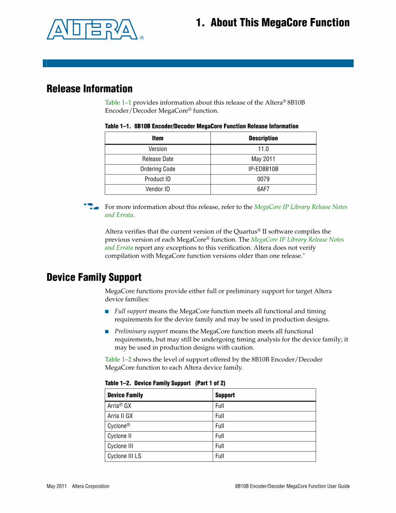
Release InformationTable 1–1 provides information about this release of the Altera® 8B10B Encoder/Decoder MegaCore® function.
f For more information about this release, refer to the MegaCore IP Library Release Notes and Errata.
Altera verifies that the current version of the Quartus® II software compiles the previous version of each MegaCore® function. The MegaCore IP Library Release Notes and Errata report any exceptions to this verification. Altera does not verify compilation with MegaCore function versions older than one release."
Device Family SupportMegaCore functions provide either full or preliminary support for target Altera device families:
■ Full support means the MegaCore function meets all functional and timing requirements for the device family and may be used in production designs.
■ Preliminary support means the MegaCore function meets all functional requirements, but may still be undergoing timing analysis for the device family; it may be used in production designs with caution.
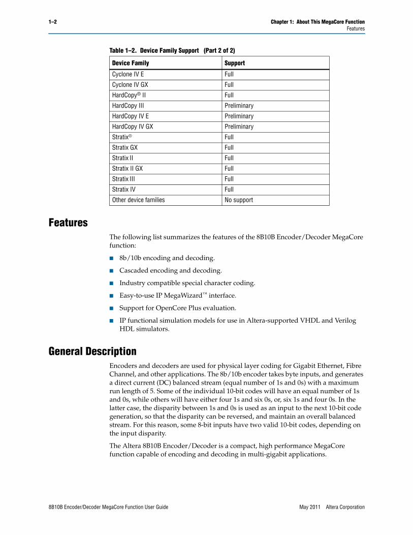
Table 1–2 shows the level of support offered by the 8B10B Encoder/Decoder MegaCore function to each Altera device family.
Table 1–1. 8B10B Encoder/Decoder MegaCore Function Release Information
Item Description
Version 11.0
Release Date May 2011
Ordering Code IP-ED8B10B
Product ID 0079
Vendor ID 6AF7
Table 1–2. Device Family Support (Part 1 of 2)
Device Family Support
Arria® GX Full
Arria II GX Full
Cyclone® Full
Cyclone II Full
Cyclone III Full
Cyclone III LS Full
8B10B Encoder/Decoder MegaCore Function User Guide
1–2 Chapter 1: About This MegaCore FunctionFeatures
FeaturesThe following list summarizes the features of the 8B10B Encoder/Decoder MegaCore function:
■ 8b/10b encoding and decoding.
■ Cascaded encoding and decoding.
■ Industry compatible special character coding.
■ Easy-to-use IP MegaWizard™ interface.
■ Support for OpenCore Plus evaluation.
■ IP functional simulation models for use in Altera-supported VHDL and Verilog HDL simulators.
General DescriptionEncoders and decoders are used for physical layer coding for Gigabit Ethernet, Fibre Channel, and other applications. The 8b/10b encoder takes byte inputs, and generates a direct current (DC) balanced stream (equal number of 1s and 0s) with a maximum run length of 5. Some of the individual 10-bit codes will have an equal number of 1s and 0s, while others will have either four 1s and six 0s, or, six 1s and four 0s. In the latter case, the disparity between 1s and 0s is used as an input to the next 10-bit code generation, so that the disparity can be reversed, and maintain an overall balanced stream. For this reason, some 8-bit inputs have two valid 10-bit codes, depending on the input disparity.
The Altera 8B10B Encoder/Decoder is a compact, high performance MegaCore function capable of encoding and decoding in multi-gigabit applications.
Cyclone IV E Full
Cyclone IV GX Full
HardCopy® II Full
HardCopy III Preliminary
HardCopy IV E Preliminary
HardCopy IV GX Preliminary
Stratix® Full
Stratix GX Full
Stratix II Full
Stratix II GX Full
Stratix III Full
Stratix IV Full
Other device families No support
Table 1–2. Device Family Support (Part 2 of 2)
Device Family Support
8B10B Encoder/Decoder MegaCore Function User Guide May 2011 Altera Corporation
Chapter 1: About This MegaCore Function 1–3Performance and Resource Utilization
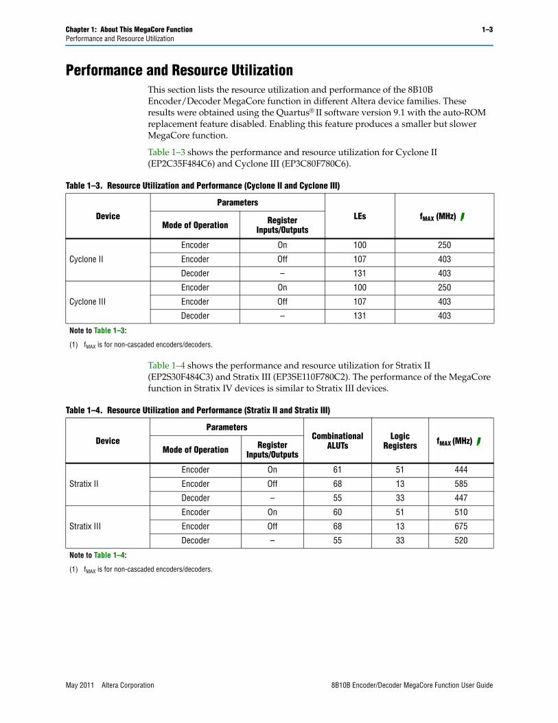
Performance and Resource UtilizationThis section lists the resource utilization and performance of the 8B10B Encoder/Decoder MegaCore function in different Altera device families. These results were obtained using the Quartus® II software version 9.1 with the auto-ROM replacement feature disabled. Enabling this feature produces a smaller but slower MegaCore function.
Table 1–3 shows the performance and resource utilization for Cyclone II (EP2C35F484C6) and Cyclone III (EP3C80F780C6).
Table 1–4 shows the performance and resource utilization for Stratix II (EP2S30F484C3) and Stratix III (EP3SE110F780C2). The performance of the MegaCore function in Stratix IV devices is similar to Stratix III devices.
Table 1–3. Resource Utilization and Performance (Cyclone II and Cyclone III)
Device
Parameters
LEs fMAX (MHz) (1)Mode of Operation Register
Inputs/Outputs
Cyclone II
Encoder On 100 250
Encoder Off 107 403
Decoder – 131 403
Cyclone III
Encoder On 100 250
Encoder Off 107 403
Decoder – 131 403
Note to Table 1–3:
(1) fMAX is for non-cascaded encoders/decoders.
Table 1–4. Resource Utilization and Performance (Stratix II and Stratix III)
Device
ParametersCombinational
ALUTsLogic
Registers fMAX (MHz) (1)Mode of Operation Register
Inputs/Outputs
Stratix II
Encoder On 61 51 444
Encoder Off 68 13 585
Decoder – 55 33 447
Stratix III
Encoder On 60 51 510
Encoder Off 68 13 675
Decoder – 55 33 520
Note to Table 1–4:
(1) fMAX is for non-cascaded encoders/decoders.
May 2011 Altera Corporation 8B10B Encoder/Decoder MegaCore Function User Guide
1–4 Chapter 1: About This MegaCore FunctionInstallation and Licensing
Installation and LicensingThe 8B10B Encoder/Decoder MegaCore Function is part of the MegaCore® IP Library, which is distributed with the Quartus® II software and downloadable from the Altera® website, www.altera.com.
f For system requirements and installation instructions, refer to Altera Software Installation and Licensing.
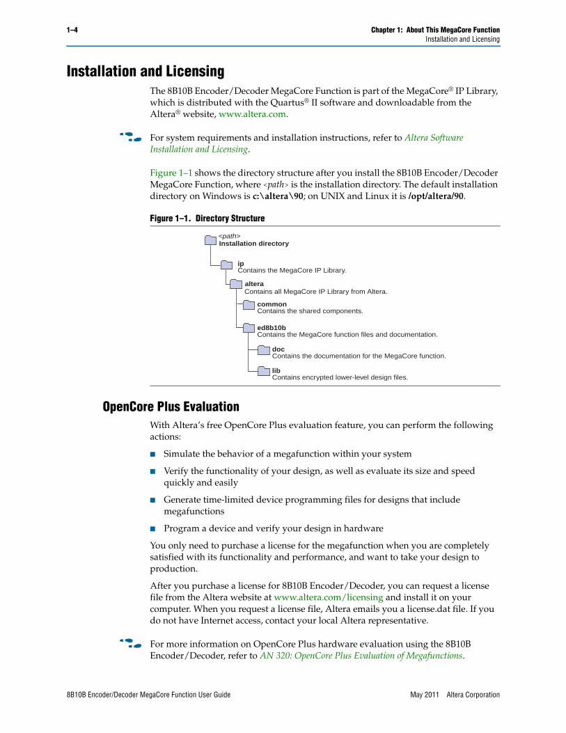
Figure 1–1 shows the directory structure after you install the 8B10B Encoder/Decoder MegaCore Function, where <path> is the installation directory. The default installation directory on Windows is c:\altera\90; on UNIX and Linux it is /opt/altera/90.
OpenCore Plus EvaluationWith Altera’s free OpenCore Plus evaluation feature, you can perform the following actions:
■ Simulate the behavior of a megafunction within your system
■ Verify the functionality of your design, as well as evaluate its size and speed quickly and easily
■ Generate time-limited device programming files for designs that include megafunctions
■ Program a device and verify your design in hardware
You only need to purchase a license for the megafunction when you are completely satisfied with its functionality and performance, and want to take your design to production.
After you purchase a license for 8B10B Encoder/Decoder, you can request a license file from the Altera website at www.altera.com/licensing and install it on your computer. When you request a license file, Altera emails you a license.dat file. If you do not have Internet access, contact your local Altera representative.
f For more information on OpenCore Plus hardware evaluation using the 8B10B Encoder/Decoder, refer to AN 320: OpenCore Plus Evaluation of Megafunctions.
Figure 1–1. Directory Structure
ed8b10bContains the MegaCore function files and documentation.
docContains the documentation for the MegaCore function.
libContains encrypted lower-level design files.
<path>
commonContains the shared components.
ipContains the MegaCore IP Library.
Installation directory
alteraContains all MegaCore IP Library from Altera.
8B10B Encoder/Decoder MegaCore Function User Guide May 2011 Altera Corporation
Chapter 1: About This MegaCore Function 1–5Installation and Licensing
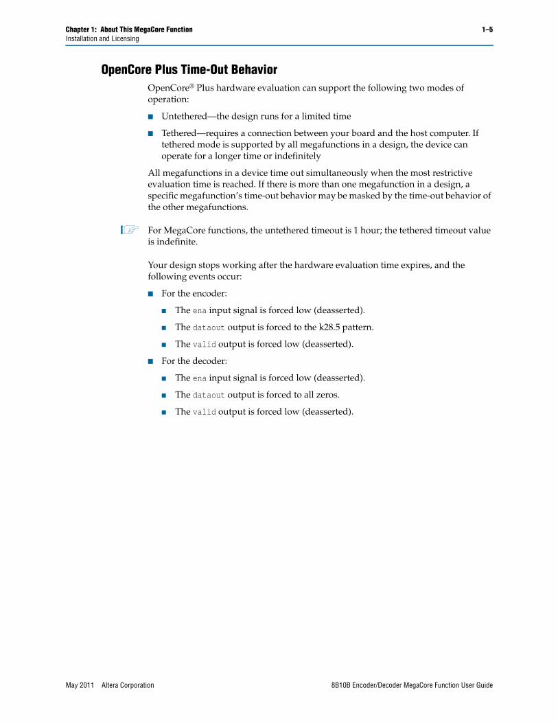
OpenCore Plus Time-Out BehaviorOpenCore® Plus hardware evaluation can support the following two modes of operation:
■ Untethered—the design runs for a limited time
■ Tethered—requires a connection between your board and the host computer. If tethered mode is supported by all megafunctions in a design, the device can operate for a longer time or indefinitely
All megafunctions in a device time out simultaneously when the most restrictive evaluation time is reached. If there is more than one megafunction in a design, a specific megafunction’s time-out behavior may be masked by the time-out behavior of the other megafunctions.
1 For MegaCore functions, the untethered timeout is 1 hour; the tethered timeout value is indefinite.
Your design stops working after the hardware evaluation time expires, and the following events occur:
■ For the encoder:
■ The ena input signal is forced low (deasserted).
■ The dataout output is forced to the k28.5 pattern.
■ The valid output is forced low (deasserted).
■ For the decoder:
■ The ena input signal is forced low (deasserted).
■ The dataout output is forced to all zeros.
■ The valid output is forced low (deasserted).
May 2011 Altera Corporation 8B10B Encoder/Decoder MegaCore Function User Guide

1–6 Chapter 1: About This MegaCore FunctionInstallation and Licensing
8B10B Encoder/Decoder MegaCore Function User Guide May 2011 Altera Corporation
May 2011 Altera Corporation
2. Getting Started
Design FlowTo evaluate the 8B10B Encoder/Decoder MegaCore® function using the OpenCore Plus feature include these steps in your design flow:
1. Obtain and install the 8B10B Encoder/Decoder MegaCore Function.
f For more information on installation and licensing, refer to “Installation and Licensing” on page 1–4.
2. Create a custom variation of the 8B10B Encoder/Decoder MegaCore Function.
3. Implement the rest of your design using the design entry method of your choice.
4. Use the IP functional simulation model to verify the operation of your design.
f For more information on IP functional simulation models, refer to the Simulating Altera IP in Third-Party Simulation Tools chapter in Volume 3 of the Quartus II Handbook.
5. Use the Quartus II software to compile your design.
1 You can also generate an OpenCore Plus time-limited programming file, which you can use to verify the operation of your design in hardware.
6. Purchase a license for the 8B10B Encoder/Decoder MegaCore Function.
After you have purchased a license for the 8B10B Encoder/Decoder MegaCore Function, follow these additional steps:
1. Set up licensing.
2. Generate a programming file for the Altera® device(s) on your board.
3. Program the Altera device(s) with the completed design.
8B10B Encoder /Decoder WalkthroughThis walkthrough shows you how to create an 8B10B Encoder/Decoder MegaCore function using the MegaWizard interface and the Quartus II software. After generating a custom variation of the 8B10B Encoder/Decoder MegaCore function, you can incorporate it into your overall project.
This walkthrough consists of the following steps:
■ Create a New Quartus II Project
■ Launch MegaWizard Plug-in Manager
■ Parameterize
■ Set Up Simulation
8B10B Encoder/Decoder MegaCore Function User Guide

2–2 Chapter 2: Getting Started8B10B Encoder /Decoder Walkthrough
■ Generate Files
■ Set Constraints
Create a New Quartus II ProjectYou need to create a new Quartus II project with the New Project Wizard, which specifies the working directory for the project, assigns the project name, and designates the name of the top-level design entity.
To create a new project follow these steps:
1. Choose Programs > Altera > Quartus II <version> (Windows Start menu) to run the Quartus II software. Alternatively, you can use the Quartus II Web Edition software.
2. Choose New Project Wizard (File menu).
3. Click Next in the New Project Wizard Introduction page (the introduction does not display if you turned it off previously).
4. In the New Project Wizard: Directory, Name, Top-Level Entity page, enter the following information:
a. Specify the working directory for your project. For example, this walkthrough uses the directory:
c:\altera\projects\ed8b10b_project
b. Specify the name of the project. This walkthrough uses the project name:
ed8b10b_example
1 The Quartus II software automatically specifies a top-level design entity that has the same name as the project. Do not change it.
5. Click Next to close this page and display the New Project Wizard: Add Files page.
1 When you specify a directory that does not already exist, a message asks if the specified directory should be created. Click Yes to create the directory.
6. If you installed the MegaCore IP Library in a different directory from where you installed the Quartus II software, you must add the user libraries:
a. Click User Libraries.
b. Type <path>\ip\altera into the Library name box, where <path> is the directory in which you installed the 8B10B Encoder/Decoder MegaCore Function.
c. Click Add to add the path to the Quartus II project.
d. Click OK to save the library path in the project.
7. Click Next to close this page and display the New Project Wizard: Family & Device Settings page.
8. On the New Project Wizard: Family & Device Settings page, choose the target device family in the Family list.
8B10B Encoder/Decoder MegaCore Function User Guide May 2011 Altera Corporation

Chapter 2: Getting Started 2–38B10B Encoder /Decoder Walkthrough
9. The remaining pages in the New Project Wizard are optional. Click Finish to complete the Quartus II project.
You have finished creating your new Quartus II project.
Launch MegaWizard Plug-in ManagerTo launch the MegaWizard Plug-in Manager in the Quartus II software, follow these steps:
1. Start the MegaWizard® Plug-In Manager by choosing the MegaWizard Plug-In Manager command (Tools menu). The MegaWizard Plug-In Manager dialog box displays.
f Refer to the Quartus II Help for more information on how to use the MegaWizard Plug-In Manager.
2. Specify that you want to create a new custom megafunction variation and click Next.
3. Expand the Communications > Encoding/Decoding directory, then click 8B10B Encoder-Decoder v9.1.
4. Choose the device family you want to use for this MegaCore function, for example Stratix II GX.
5. Select the output file type for your design; the MegaWizard interface supports VHDL and Verilog HDL.
6. The MegaWizard Plug-In Manager shows the project path that you specified in the New Project Wizard. Append a variation name for the MegaCore function output files <project path>\<variation name>.
7. Click Next to display the Parameter Settings page for the 8B10B Encoder/Decoder MegaCore Function.
1 You can change the page that the MegaWizard Plug-In Manager displays by clicking Next or Back at the bottom of the dialog box. You can move directly to a named page by clicking the Parameter Settings, EDA, or Summary tab.
ParameterizeTo parameterize your MegaCore function, perform the following steps:
1. Select the mode of operation, either Encoder or Decoder.
2. If you selected Encoder, turn on the Register inputs/outputs check box for a three-cycle latency, or turn off the Register inputs/outputs check box for a single-cycle latency.
1 The Decoder always has registered inputs and outputs.
3. Click Next (or the EDA tab) to display the simulation setup page .
May 2011 Altera Corporation 8B10B Encoder/Decoder MegaCore Function User Guide
2–4 Chapter 2: Getting Started8B10B Encoder /Decoder Walkthrough
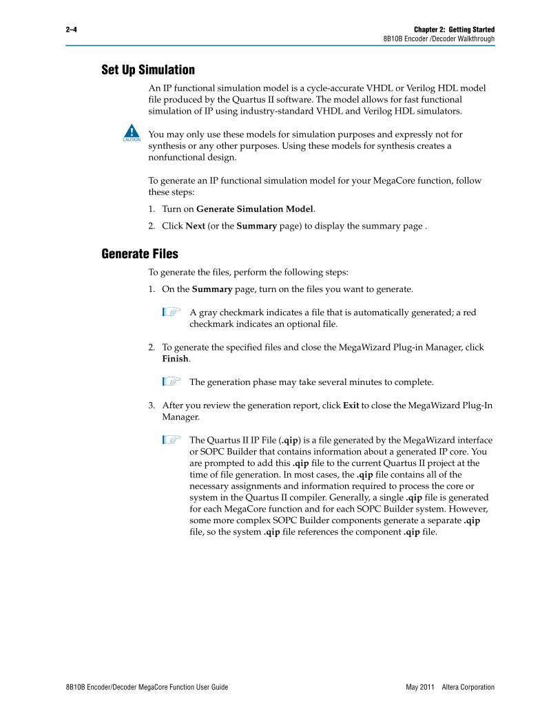
Set Up SimulationAn IP functional simulation model is a cycle-accurate VHDL or Verilog HDL model file produced by the Quartus II software. The model allows for fast functional simulation of IP using industry-standard VHDL and Verilog HDL simulators.
c You may only use these models for simulation purposes and expressly not for synthesis or any other purposes. Using these models for synthesis creates a nonfunctional design.
To generate an IP functional simulation model for your MegaCore function, follow these steps:
1. Turn on Generate Simulation Model.
2. Click Next (or the Summary page) to display the summary page .
Generate FilesTo generate the files, perform the following steps:
1. On the Summary page, turn on the files you want to generate.
1 A gray checkmark indicates a file that is automatically generated; a red checkmark indicates an optional file.
2. To generate the specified files and close the MegaWizard Plug-in Manager, click Finish.
1 The generation phase may take several minutes to complete.
3. After you review the generation report, click Exit to close the MegaWizard Plug-In Manager.
1 The Quartus II IP File (.qip) is a file generated by the MegaWizard interface or SOPC Builder that contains information about a generated IP core. You are prompted to add this .qip file to the current Quartus II project at the time of file generation. In most cases, the .qip file contains all of the necessary assignments and information required to process the core or system in the Quartus II compiler. Generally, a single .qip file is generated for each MegaCore function and for each SOPC Builder system. However, some more complex SOPC Builder components generate a separate .qip file, so the system .qip file references the component .qip file.
8B10B Encoder/Decoder MegaCore Function User Guide May 2011 Altera Corporation
Chapter 2: Getting Started 2–58B10B Encoder /Decoder Walkthrough
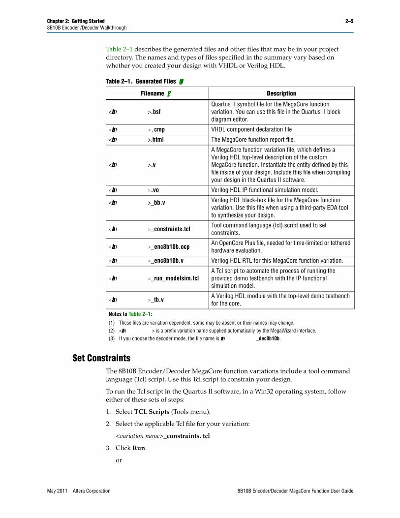
Table 2–1 describes the generated files and other files that may be in your project directory. The names and types of files specified in the summary vary based on whether you created your design with VHDL or Verilog HDL.
Set ConstraintsThe 8B10B Encoder/Decoder MegaCore function variations include a tool command language (Tcl) script. Use this Tcl script to constrain your design.
To run the Tcl script in the Quartus II software, in a Win32 operating system, follow either of these sets of steps:
1. Select TCL Scripts (Tools menu).
2. Select the applicable Tcl file for your variation:
<variation name>_constraints. tcl
3. Click Run.
or
Table 2–1. Generated Files (Note 1)
Filename (2) Description
<variation name>.bsfQuartus II symbol file for the MegaCore function variation. You can use this file in the Quartus II block diagram editor.
<variation name>.cmp VHDL component declaration file
<variation name>.html The MegaCore function report file.
<variation name>.v
A MegaCore function variation file, which defines a Verilog HDL top-level description of the custom MegaCore function. Instantiate the entity defined by this file inside of your design. Include this file when compiling your design in the Quartus II software.
<variation name>.vo Verilog HDL IP functional simulation model.
<variation name>_bb.v Verilog HDL black-box file for the MegaCore function variation. Use this file when using a third-party EDA tool to synthesize your design.
<variation name>_constraints.tcl Tool command language (tcl) script used to set constraints.
<variation name>_enc8b10b.ocp An OpenCore Plus file, needed for time-limited or tethered hardware evaluation.
<variation name>_enc8b10b.v Verilog HDL RTL for this MegaCore function variation.
<variation name>_run_modelsim.tclA Tcl script to automate the process of running the provided demo testbench with the IP functional simulation model.
<variation name>_tb.v A Verilog HDL module with the top-level demo testbench for the core.
Notes to Table 2–1:
(1) These files are variation dependent, some may be absent or their names may change.(2) <variation name> is a prefix variation name supplied automatically by the MegaWizard interface.(3) If you choose the decoder mode, the file name is <variation name>_dec8b10b.
May 2011 Altera Corporation 8B10B Encoder/Decoder MegaCore Function User Guide
2–6 Chapter 2: Getting StartedSimulate the Design
4. Click on Tcl Console under Utility_Windows (View menu).
5. In the Tcl console window, type:
source <variation name>_constraints.tcl
To run the Tcl script in a UNIX or Linux operating system terminal, type:
cd..<project_directory>quartus_sh -t <variation name>_constraints.tcl
1 Depending on the type of constraints applied by the Tcl script, analysis and synthesis may be run twice. For example, if hierarchy independent constraints are needed, the Tcl script runs analysis and synthesis before applying the constraints. Therefore, when you run a full compilation, after running the Tcl script, the analysis and synthesis are run a second time.
You can now integrate your custom MegaCore function variation into your design, simulate, and compile.
Simulate the DesignYou can simulate your design using the generated VHDL and Verilog HDL IP functional simulation models.
f For more information on IP functional simulation models, refer to the Simulating Altera IP in Third-Party Simulation Tools chapter in Volume 3 of the Quartus II Handbook.
Altera also provides a Verilog HDL demonstration testbench, including scripts to compile and run the demonstration testbench using a variety of simulators and models. This testbench demonstrates the typical behavior of an 8B10B MegaCore function, and how to instantiate a model in a design. The demonstration testbench does not perform any error checking.
f For a complete list of models or libraries required to simulate the 8B10B Encoder/Decoder MegaCore function, refer to the _run_modelsim.tcl scripts provided with the demonstration testbench.
IP Functional Simulation ModelTo use the demonstration testbench with IP functional simulation models in the ModelSim® simulator, follow these steps:
1. Start the ModelSim simulator.
2. From the ModelSim File menu, use Change Directory to change the working directory to the directory where you created your 8B10B Encoder/Decoder variation.
3. In the ModelSim Transcript window, execute the command do <variation_name>_run_modelsim.tcl which sets up the required libraries, compiles the netlist files, and runs the testbench. The ModelSim Transcript window displays messages from the testbench reflecting the results of the simulation.
8B10B Encoder/Decoder MegaCore Function User Guide May 2011 Altera Corporation
Chapter 2: Getting Started 2–7Compile the Design
1 In all cases, the testbench is in Verilog HDL, therefore a license to run mixed language simulations is required to run the testbench with the VHDL model.
Altera recommends that you disable the auto-ROM replacement feature in the Quartus II software. Enabling this feature produces a smaller but slower MegaCore function.
Compile the DesignYou can use the Quartus II software to compile your design. Refer to Quartus II Help for instructions on compiling your design.
Program a DeviceAfter you have compiled your design, program your targeted Altera device, and verify your design in hardware.
May 2011 Altera Corporation 8B10B Encoder/Decoder MegaCore Function User Guide

2–8 Chapter 2: Getting StartedProgram a Device
8B10B Encoder/Decoder MegaCore Function User Guide May 2011 Altera Corporation
May 2011 Altera Corporation
3. Specifications
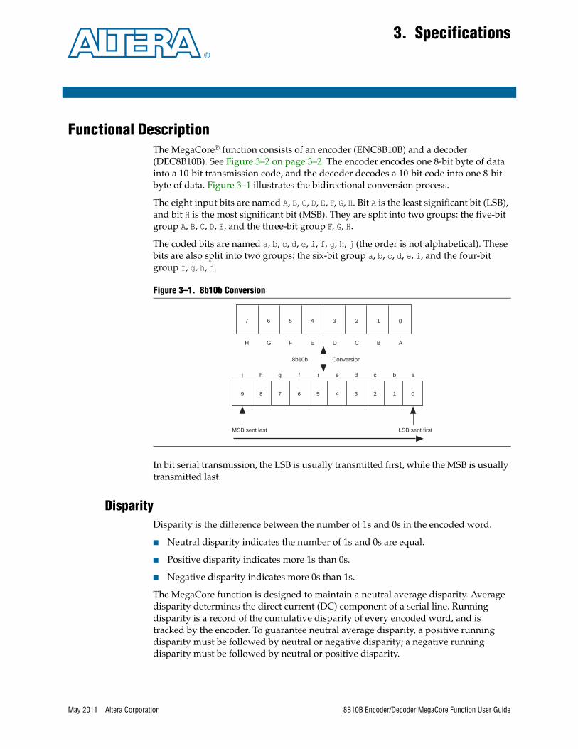
Functional DescriptionThe MegaCore® function consists of an encoder (ENC8B10B) and a decoder (DEC8B10B). See Figure 3–2 on page 3–2. The encoder encodes one 8-bit byte of data into a 10-bit transmission code, and the decoder decodes a 10-bit code into one 8-bit byte of data. Figure 3–1 illustrates the bidirectional conversion process.
The eight input bits are named A, B, C, D, E, F, G, H. Bit A is the least significant bit (LSB), and bit H is the most significant bit (MSB). They are split into two groups: the five-bit group A, B, C, D, E, and the three-bit group F, G, H.
The coded bits are named a, b, c, d, e, i, f, g, h, j (the order is not alphabetical). These bits are also split into two groups: the six-bit group a, b, c, d, e, i, and the four-bit group f, g, h, j.
In bit serial transmission, the LSB is usually transmitted first, while the MSB is usually transmitted last.
DisparityDisparity is the difference between the number of 1s and 0s in the encoded word.
■ Neutral disparity indicates the number of 1s and 0s are equal.
■ Positive disparity indicates more 1s than 0s.
■ Negative disparity indicates more 0s than 1s.
The MegaCore function is designed to maintain a neutral average disparity. Average disparity determines the direct current (DC) component of a serial line. Running disparity is a record of the cumulative disparity of every encoded word, and is tracked by the encoder. To guarantee neutral average disparity, a positive running disparity must be followed by neutral or negative disparity; a negative running disparity must be followed by neutral or positive disparity.
Figure 3–1. 8b10b Conversion
9 8 7 6 5 4 3 2 1 0
7 6 5 4 3 2 1 0
H G F E D C B A
abcdeifghj
Conversion8b10b
LSB sent firstMSB sent last
8B10B Encoder/Decoder MegaCore Function User Guide
3–2 Chapter 3: SpecificationsFunctional Description
The running disparity error output (rderr) is asserted when any of the following rules apply:
■ The current running disparity is positive and the 6-bit group has more ones than zeros or is 111000.
■ The current running disparity is negative and the 6-bit group has more zeros than ones or is 000111.
■ The running disparity after 6-bit group is positive and the 4-bit group has more ones than zeros or is 1100.
■ The running disparity after 6-bit group is negative and the 4-bit group has more zeros than ones or is 0011.
1 rderr is asserted for some invalid 10-bit codes and not for others, strictly based on the rules stated above. The computation of rderr is completely independent of that of the special control character error (kerr) signal.
A 10-bit code that corresponds to a valid encoding but that has the wrong disparity—though technically an invalid code—does not cause the kerr signal to be asserted. Only rderr is asserted.
f For details on running disparity rules, refer to the IEEE 802.3z specification, paragraph 36.2.4.4.
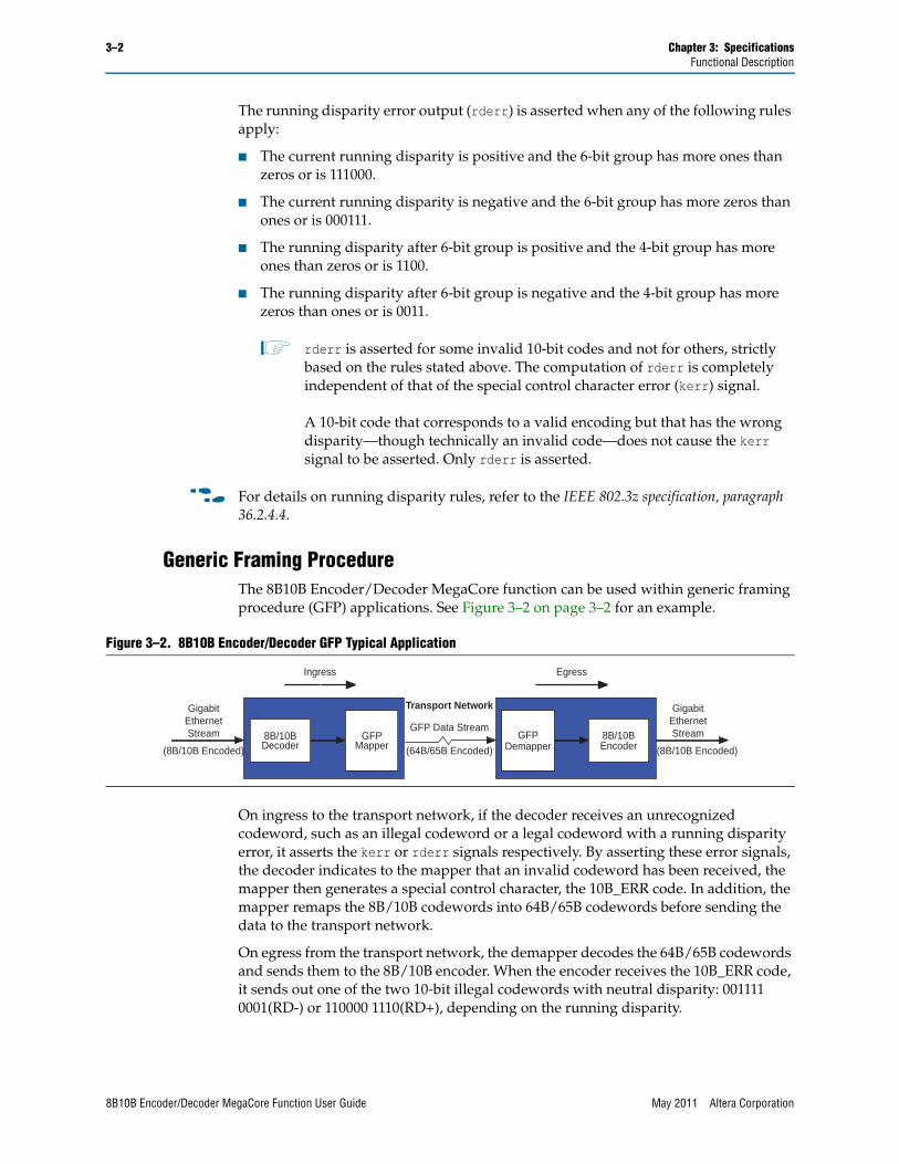
Generic Framing ProcedureThe 8B10B Encoder/Decoder MegaCore function can be used within generic framing procedure (GFP) applications. See Figure 3–2 on page 3–2 for an example.
On ingress to the transport network, if the decoder receives an unrecognized codeword, such as an illegal codeword or a legal codeword with a running disparity error, it asserts the kerr or rderr signals respectively. By asserting these error signals, the decoder indicates to the mapper that an invalid codeword has been received, the mapper then generates a special control character, the 10B_ERR code. In addition, the mapper remaps the 8B/10B codewords into 64B/65B codewords before sending the data to the transport network.
On egress from the transport network, the demapper decodes the 64B/65B codewords and sends them to the 8B/10B encoder. When the encoder receives the 10B_ERR code, it sends out one of the two 10-bit illegal codewords with neutral disparity: 001111 0001(RD-) or 110000 1110(RD+), depending on the running disparity.
Figure 3–2. 8B10B Encoder/Decoder GFP Typical Application
(64B/65B Encoded)
Transport Network
GFP Data Stream
DemapperGFP
Encoder8B/10B
Decoder8B/10B
MapperGFP
GigabitEthernetStream
(8B/10B Encoded)
GigabitEthernetStream
(8B/10B Encoded)
Ingress Egress
8B10B Encoder/Decoder MegaCore Function User Guide May 2011 Altera Corporation
Chapter 3: Specifications 3–3Functional Description
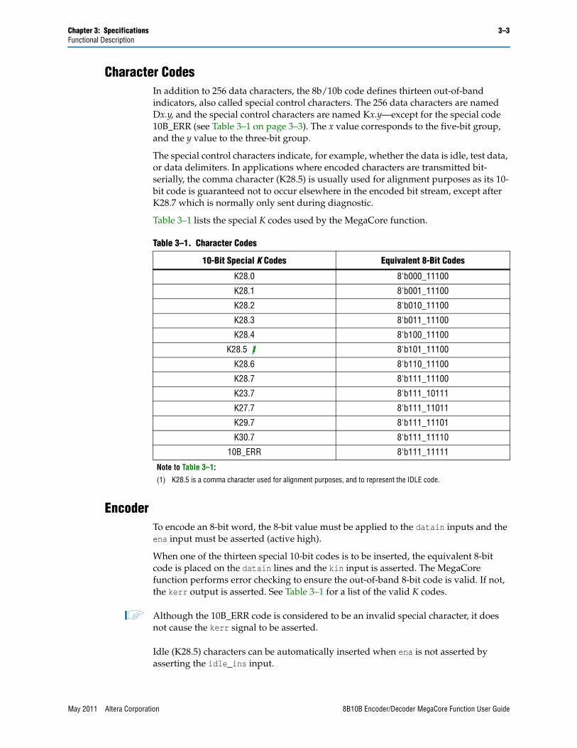
Character CodesIn addition to 256 data characters, the 8b/10b code defines thirteen out-of-band indicators, also called special control characters. The 256 data characters are named Dx.y, and the special control characters are named Kx.y—except for the special code 10B_ERR (see Table 3–1 on page 3–3). The x value corresponds to the five-bit group, and the y value to the three-bit group.
The special control characters indicate, for example, whether the data is idle, test data, or data delimiters. In applications where encoded characters are transmitted bit-serially, the comma character (K28.5) is usually used for alignment purposes as its 10-bit code is guaranteed not to occur elsewhere in the encoded bit stream, except after K28.7 which is normally only sent during diagnostic.
Table 3–1 lists the special K codes used by the MegaCore function.
EncoderTo encode an 8-bit word, the 8-bit value must be applied to the datain inputs and the ena input must be asserted (active high).
When one of the thirteen special 10-bit codes is to be inserted, the equivalent 8-bit code is placed on the datain lines and the kin input is asserted. The MegaCore function performs error checking to ensure the out-of-band 8-bit code is valid. If not, the kerr output is asserted. See Table 3–1 for a list of the valid K codes.
1 Although the 10B_ERR code is considered to be an invalid special character, it does not cause the kerr signal to be asserted.
Idle (K28.5) characters can be automatically inserted when ena is not asserted by asserting the idle_ins input.
Table 3–1. Character Codes
10-Bit Special K Codes Equivalent 8-Bit Codes
K28.0 8'b000_11100
K28.1 8'b001_11100
K28.2 8'b010_11100
K28.3 8'b011_11100
K28.4 8'b100_11100
K28.5 (1) 8'b101_11100
K28.6 8'b110_11100
K28.7 8'b111_11100
K23.7 8'b111_10111
K27.7 8'b111_11011
K29.7 8'b111_11101
K30.7 8'b111_11110
10B_ERR 8'b111_11111
Note to Table 3–1:
(1) K28.5 is a comma character used for alignment purposes, and to represent the IDLE code.
May 2011 Altera Corporation 8B10B Encoder/Decoder MegaCore Function User Guide
3–4 Chapter 3: SpecificationsFunctional Description
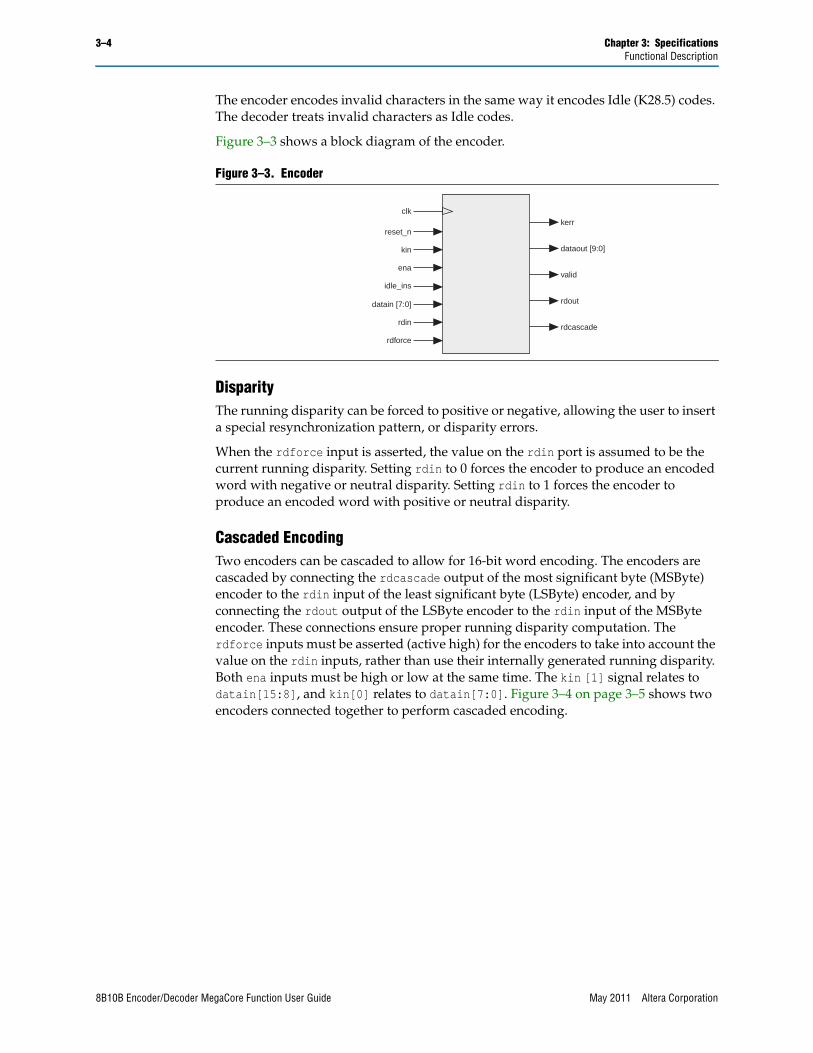
The encoder encodes invalid characters in the same way it encodes Idle (K28.5) codes. The decoder treats invalid characters as Idle codes.
Figure 3–3 shows a block diagram of the encoder.
DisparityThe running disparity can be forced to positive or negative, allowing the user to insert a special resynchronization pattern, or disparity errors.
When the rdforce input is asserted, the value on the rdin port is assumed to be the current running disparity. Setting rdin to 0 forces the encoder to produce an encoded word with negative or neutral disparity. Setting rdin to 1 forces the encoder to produce an encoded word with positive or neutral disparity.
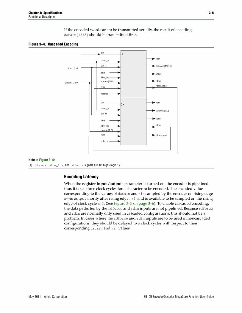
Cascaded EncodingTwo encoders can be cascaded to allow for 16-bit word encoding. The encoders are cascaded by connecting the rdcascade output of the most significant byte (MSByte) encoder to the rdin input of the least significant byte (LSByte) encoder, and by connecting the rdout output of the LSByte encoder to the rdin input of the MSByte encoder. These connections ensure proper running disparity computation. The rdforce inputs must be asserted (active high) for the encoders to take into account the value on the rdin inputs, rather than use their internally generated running disparity. Both ena inputs must be high or low at the same time. The kin [1] signal relates to datain[15:8], and kin[0] relates to datain[7:0]. Figure 3–4 on page 3–5 shows two encoders connected together to perform cascaded encoding.
Figure 3–3. Encoder
clk
reset_n
kin
ena
rdinrdcascade
rdout
valid
kerr
datain [7:0]
dataout [9:0]
rdforce
idle_ins
8B10B Encoder/Decoder MegaCore Function User Guide May 2011 Altera Corporation
Chapter 3: Specifications 3–5Functional Description
If the encoded words are to be transmitted serially, the result of encoding datain[15:8] should be transmitted first.
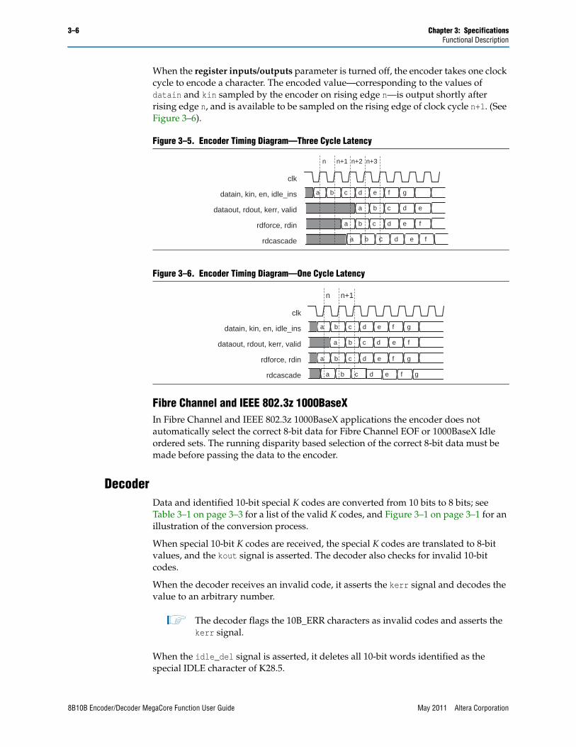
Encoding LatencyWhen the register inputs/outputs parameter is turned on, the encoder is pipelined, thus it takes three clock cycles for a character to be encoded. The encoded value—corresponding to the values of datain and kin sampled by the encoder on rising edge n—is output shortly after rising edge n+2, and is available to be sampled on the rising edge of clock cycle n+3. (See Figure 3–5 on page 3–6). To enable cascaded encoding, the data paths fed by the rdforce and rdin inputs are not pipelined. Because rdforce and rdin are normally only used in cascaded configurations, this should not be a problem. In cases where the rdforce and rdin inputs are to be used in noncascaded configurations, they should be delayed two clock cycles with respect to their corresponding datain and kin values.
Figure 3–4. Cascaded Encoding
Note to Figure 3–4:
(1) The ena, idle_ins, and rdforce signals are set high (logic 1).
clk
reset_n
rdout
valid
kerr
clk
reset_n
rdcascade
valid
kerr
rdout
rdin
dataout [19:10]
rdcascade
rdin
[1:0]kin
[15:0]datain
ena
rdforce
ena
rdforce
datain [7:0]
datain [15:8]
dataout [9:0]kin [0]
kin [1]
idle_ins
idle_ins
May 2011 Altera Corporation 8B10B Encoder/Decoder MegaCore Function User Guide
3–6 Chapter 3: SpecificationsFunctional Description
When the register inputs/outputs parameter is turned off, the encoder takes one clock cycle to encode a character. The encoded value—corresponding to the values of datain and kin sampled by the encoder on rising edge n—is output shortly after rising edge n, and is available to be sampled on the rising edge of clock cycle n+1. (See Figure 3–6).
Fibre Channel and IEEE 802.3z 1000BaseXIn Fibre Channel and IEEE 802.3z 1000BaseX applications the encoder does not automatically select the correct 8-bit data for Fibre Channel EOF or 1000BaseX Idle ordered sets. The running disparity based selection of the correct 8-bit data must be made before passing the data to the encoder.
DecoderData and identified 10-bit special K codes are converted from 10 bits to 8 bits; see Table 3–1 on page 3–3 for a list of the valid K codes, and Figure 3–1 on page 3–1 for an illustration of the conversion process.
When special 10-bit K codes are received, the special K codes are translated to 8-bit values, and the kout signal is asserted. The decoder also checks for invalid 10-bit codes.
When the decoder receives an invalid code, it asserts the kerr signal and decodes the value to an arbitrary number.
1 The decoder flags the 10B_ERR characters as invalid codes and asserts the kerr signal.
When the idle_del signal is asserted, it deletes all 10-bit words identified as the special IDLE character of K28.5.
Figure 3–5. Encoder Timing Diagram—Three Cycle Latency
Figure 3–6. Encoder Timing Diagram—One Cycle Latency
clk
datain, kin, en, idle_ins
dataout, rdout, kerr, valid
rdforce, rdin
rdcascade
a b c d e f g
a b c d e
a b c d e f
a b c d e f
n+1 n+2 n+3n
clk
datain, kin, en, idle_ins
dataout, rdout, kerr, valid
rdforce, rdin
rdcascade
a b c d e f g
a b c d e f
a b c d e f g
n+1
a b c d e f g
n
8B10B Encoder/Decoder MegaCore Function User Guide May 2011 Altera Corporation
Chapter 3: Specifications 3–7Functional Description
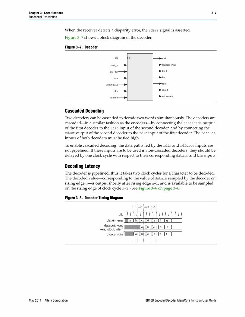
When the receiver detects a disparity error, the rderr signal is asserted.
Figure 3–7 shows a block diagram of the decoder.
Cascaded DecodingTwo decoders can be cascaded to decode two words simultaneously. The decoders are cascaded—in a similar fashion as the encoders—by connecting the rdcascade output of the first decoder to the rdin input of the second decoder, and by connecting the rdout output of the second decoder to the rdin input of the first decoder. The rdforce inputs of both decoders must be tied high.
To enable cascaded decoding, the data paths fed by the rdin and rdforce inputs are not pipelined. If these inputs are to be used in non-cascaded decoders, they should be delayed by one clock cycle with respect to their corresponding datain and kin inputs.
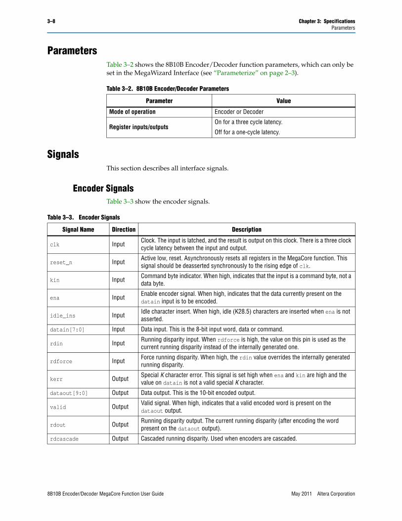
Decoding LatencyThe decoder is pipelined, thus it takes two clock cycles for a character to be decoded. The decoded value—corresponding to the value of datain sampled by the decoder on rising edge n—is output shortly after rising edge n+1, and is available to be sampled on the rising edge of clock cycle n+2. (See Figure 3–6 on page 3–6).
Figure 3–7. Decoder
Figure 3–8. Decoder Timing Diagram
clk
reset_n
idle_del
ena
datain [9:0]
valid
dataout [7:0]
kout
kerr
rderr
rdin
rdforce
rdout
rdcascade
clk
datain, ena
rdforce, rdin
a b c d e f g
a b c d e
a b c d e f
n+1n n+2 n+3
dataout, koutkerr, rdout, rderr
May 2011 Altera Corporation 8B10B Encoder/Decoder MegaCore Function User Guide
3–8 Chapter 3: SpecificationsParameters
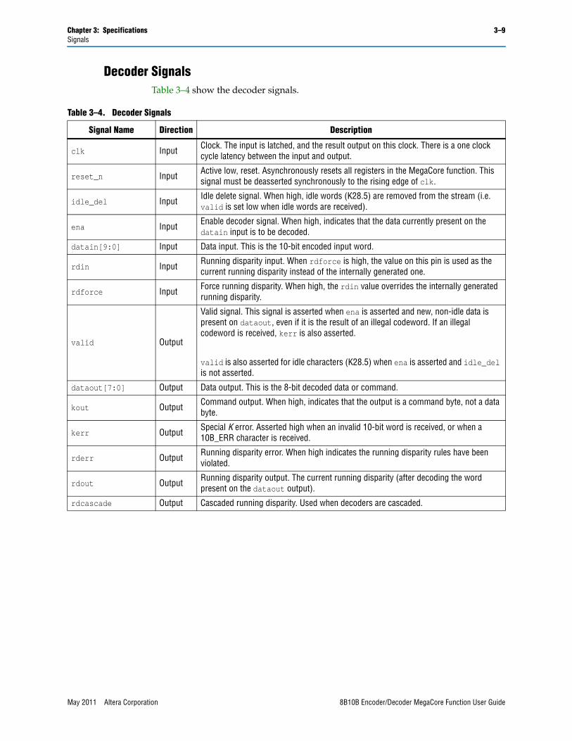
ParametersTable 3–2 shows the 8B10B Encoder/Decoder function parameters, which can only be set in the MegaWizard Interface (see “Parameterize” on page 2–3).
SignalsThis section describes all interface signals.
Encoder SignalsTable 3–3 show the encoder signals.
Table 3–2. 8B10B Encoder/Decoder Parameters
Parameter Value
Mode of operation Encoder or Decoder
Register inputs/outputsOn for a three cycle latency.
Off for a one-cycle latency.
Table 3–3. Encoder Signals
Signal Name Direction Description
clk Input Clock. The input is latched, and the result is output on this clock. There is a three clock cycle latency between the input and output.
reset_n Input Active low, reset. Asynchronously resets all registers in the MegaCore function. This signal should be deasserted synchronously to the rising edge of clk.
kin Input Command byte indicator. When high, indicates that the input is a command byte, not a data byte.
ena Input Enable encoder signal. When high, indicates that the data currently present on the datain input is to be encoded.
idle_ins Input Idle character insert. When high, idle (K28.5) characters are inserted when ena is not asserted.
datain[7:0] Input Data input. This is the 8-bit input word, data or command.
rdin Input Running disparity input. When rdforce is high, the value on this pin is used as the current running disparity instead of the internally generated one.
rdforce Input Force running disparity. When high, the rdin value overrides the internally generated running disparity.
kerr Output Special K character error. This signal is set high when ena and kin are high and the value on datain is not a valid special K character.
dataout[9:0] Output Data output. This is the 10-bit encoded output.
valid Output Valid signal. When high, indicates that a valid encoded word is present on the dataout output.
rdout Output Running disparity output. The current running disparity (after encoding the word present on the dataout output).
rdcascade Output Cascaded running disparity. Used when encoders are cascaded.
8B10B Encoder/Decoder MegaCore Function User Guide May 2011 Altera Corporation
Chapter 3: Specifications 3–9Signals
Decoder SignalsTable 3–4 show the decoder signals.
Table 3–4. Decoder Signals
Signal Name Direction Description
clk Input Clock. The input is latched, and the result output on this clock. There is a one clock cycle latency between the input and output.
reset_n Input Active low, reset. Asynchronously resets all registers in the MegaCore function. This signal must be deasserted synchronously to the rising edge of clk.
idle_del Input Idle delete signal. When high, idle words (K28.5) are removed from the stream (i.e. valid is set low when idle words are received).
ena Input Enable decoder signal. When high, indicates that the data currently present on the datain input is to be decoded.
datain[9:0] Input Data input. This is the 10-bit encoded input word.
rdin Input Running disparity input. When rdforce is high, the value on this pin is used as the current running disparity instead of the internally generated one.
rdforce Input Force running disparity. When high, the rdin value overrides the internally generated running disparity.
valid Output
Valid signal. This signal is asserted when ena is asserted and new, non-idle data is present on dataout, even if it is the result of an illegal codeword. If an illegal codeword is received, kerr is also asserted.
valid is also asserted for idle characters (K28.5) when ena is asserted and idle_del is not asserted.
dataout[7:0] Output Data output. This is the 8-bit decoded data or command.
kout Output Command output. When high, indicates that the output is a command byte, not a data byte.
kerr Output Special K error. Asserted high when an invalid 10-bit word is received, or when a 10B_ERR character is received.
rderr Output Running disparity error. When high indicates the running disparity rules have been violated.
rdout Output Running disparity output. The current running disparity (after decoding the word present on the dataout output).
rdcascade Output Cascaded running disparity. Used when decoders are cascaded.
May 2011 Altera Corporation 8B10B Encoder/Decoder MegaCore Function User Guide

3–10 Chapter 3: SpecificationsSignals
8B10B Encoder/Decoder MegaCore Function User Guide May 2011 Altera Corporation
May 2011 Altera Corporation
Additional Information
This chapter provides additional information about the document and Altera.
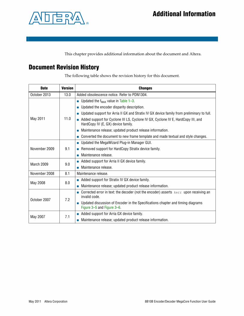
Document Revision HistoryThe following table shows the revision history for this document.
Date Version Changes
October 2013 13.0 Added obsolescence notice. Refer to PDN1304.
May 2011 11.0
■ Updated the fMAX value in Table 1–3.
■ Updated the encoder disparity description.
■ Updated support for Arria II GX and Stratix IV GX device family from preliminary to full.
■ Added support for Cyclone III LS, Cyclone IV GX, Cyclone IV E, HardCopy III, and HardCopy IV (E, GX) device family.
■ Maintenance release; updated product release information.
■ Converted the document to new frame template and made textual and style changes.
November 2009 9.1
■ Updated the MegaWizard Plug-in Manager GUI.
■ Removed support for HardCopy Stratix device family.
■ Maintenance release.
March 2009 9.0■ Added support for Arria II GX device family.
■ Maintenance release.
November 2008 8.1 Maintenance release.
May 2008 8.0■ Added support for Stratix IV GX device family.
■ Maintenance release; updated product release information.
October 2007 7.2
■ Corrected error in text: the decoder (not the encoder) asserts kerr upon receiving an invalid code.
■ Updated discussion of Encoder in the Specifications chapter and timing diagrams Figure 3–5 and Figure 3–6.
May 2007 7.1■ Added support for Arria GX device family.
■ Maintenance release; updated product release information.
8B10B Encoder/Decoder MegaCore Function User Guide
Info–2 Additional InformationHow to Contact Altera
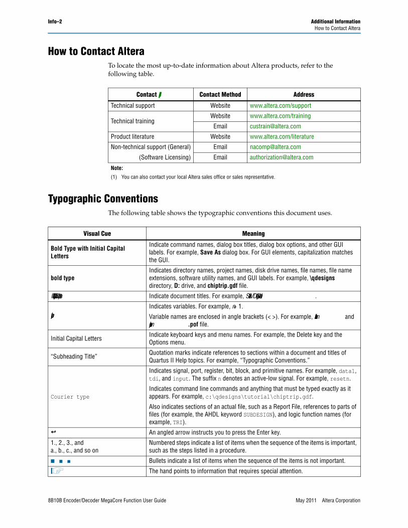
How to Contact AlteraTo locate the most up-to-date information about Altera products, refer to the following table.
Typographic ConventionsThe following table shows the typographic conventions this document uses.
Contact (1) Contact Method Address
Technical support Website www.altera.com/support
Technical trainingWebsite www.altera.com/training
Email [email protected]
Product literature Website www.altera.com/literature
Non-technical support (General) Email [email protected]
(Software Licensing) Email [email protected]
Note:
(1) You can also contact your local Altera sales office or sales representative.
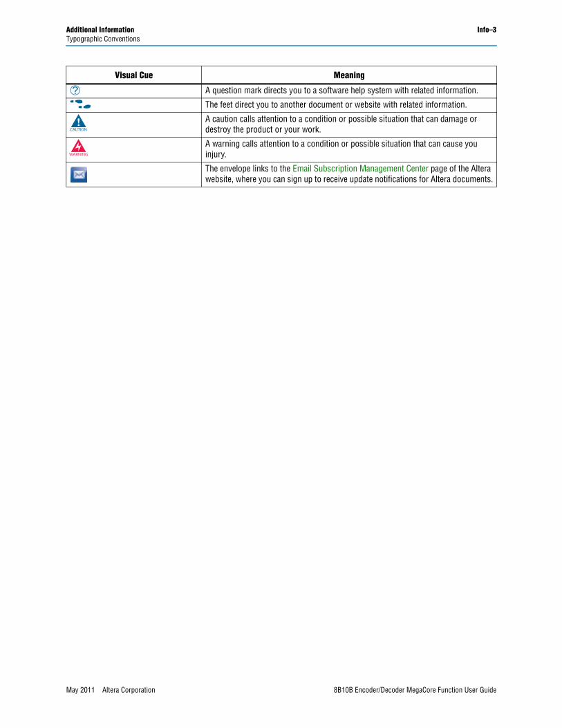
Visual Cue Meaning
Bold Type with Initial Capital Letters
Indicate command names, dialog box titles, dialog box options, and other GUI labels. For example, Save As dialog box. For GUI elements, capitalization matches the GUI.
bold typeIndicates directory names, project names, disk drive names, file names, file name extensions, software utility names, and GUI labels. For example, \qdesigns directory, D: drive, and chiptrip.gdf file.
Italic Type with Initial Capital Letters Indicate document titles. For example, Stratix IV Design Guidelines.
italic typeIndicates variables. For example, n + 1.
Variable names are enclosed in angle brackets (< >). For example, <file name> and <project name>.pof file.
Initial Capital Letters Indicate keyboard keys and menu names. For example, the Delete key and the Options menu.
“Subheading Title” Quotation marks indicate references to sections within a document and titles of Quartus II Help topics. For example, “Typographic Conventions.”
Courier type
Indicates signal, port, register, bit, block, and primitive names. For example, data1, tdi, and input. The suffix n denotes an active-low signal. For example, resetn.
Indicates command line commands and anything that must be typed exactly as it appears. For example, c:\qdesigns\tutorial\chiptrip.gdf.
Also indicates sections of an actual file, such as a Report File, references to parts of files (for example, the AHDL keyword SUBDESIGN), and logic function names (for example, TRI).
r An angled arrow instructs you to press the Enter key.
1., 2., 3., anda., b., c., and so on
Numbered steps indicate a list of items when the sequence of the items is important, such as the steps listed in a procedure.
■ ■ ■ Bullets indicate a list of items when the sequence of the items is not important.
1 The hand points to information that requires special attention.
8B10B Encoder/Decoder MegaCore Function User Guide May 2011 Altera Corporation
Additional Information Info–3Typographic Conventions
h A question mark directs you to a software help system with related information.
f The feet direct you to another document or website with related information.
c A caution calls attention to a condition or possible situation that can damage or destroy the product or your work.
w A warning calls attention to a condition or possible situation that can cause you injury.
The envelope links to the Email Subscription Management Center page of the Altera website, where you can sign up to receive update notifications for Altera documents.
Visual Cue Meaning
May 2011 Altera Corporation 8B10B Encoder/Decoder MegaCore Function User Guide

Info–4 Additional InformationTypographic Conventions
8B10B Encoder/Decoder MegaCore Function User Guide May 2011 Altera Corporation