CI502-PNIO (-XC) Description, 1, en US10 CI502-PNIO (-XC) Description 12.04.2017 Fig. 4: Connection...
34
CI502-PNIO (-XC) Description TECHNICAL DOCUMENTATION Read this manual prior to performing any task!
Transcript of CI502-PNIO (-XC) Description, 1, en US10 CI502-PNIO (-XC) Description 12.04.2017 Fig. 4: Connection...

CI502-PNIO (-XC) Description
TECHNICAL DOCUMENTATION
Read this manual prior to performing any task!

3ADR024127K0201, 1, en_US
© 2017
ABB Automation Products GmbH
Eppelheimer Straße 82
69123 Heidelberg, Germany
Telephone: +49 62 21 701 1444
Fax: +49 62 21 701 1382
E-mail: [email protected]
Internet: www.abb.com/PLC
12.04.2017CI502-PNIO (-XC) Description2

Table of contents1 CI502-PNIO (-XC)................................................................................................................................... 4
1.1 Intended Purpose............................................................................................................................ 51.2 Functionality.................................................................................................................................... 61.3 Electrical Connection...................................................................................................................... 61.3.1 Connection of the digital inputs.................................................................................................... 91.3.2 Connection of the digital outputs................................................................................................ 101.3.3 Connection of the configurable digital inputs/outputs................................................................. 111.3.4 Assignment of the Ethernet Ports.............................................................................................. 121.4 Internal Data Exchange................................................................................................................. 131.5 Addressing.................................................................................................................................... 131.6 I/O Configuration........................................................................................................................... 131.7 Parameterization........................................................................................................................... 131.7.1 Parameters of the Module.......................................................................................................... 131.7.2 Group parameters for the digital part......................................................................................... 151.8 Diagnosis...................................................................................................................................... 161.8.1 Status LEDs............................................................................................................................... 201.9 Technical Data............................................................................................................................... 211.9.1 Technical Data of the Module..................................................................................................... 211.9.2 Technical Data of the Digital Inputs............................................................................................ 231.9.3 Technical Data of the Digital Outputs......................................................................................... 241.9.4 Technical Data of the Configurable Digital Inputs/Outputs......................................................... 251.9.5 Technical Data of the Fast Counter............................................................................................ 271.10 Ordering Data.............................................................................................................................. 28
2 System Information............................................................................................................................. 292.1 PROFINET® Modules................................................................................................................... 292.1.1 Communication Modules and Communication Interface Modules............................................. 292.1.2 Device Model of PROFINET® IO Devices................................................................................. 292.1.3 Allocation of the Device Name................................................................................................... 302.2 Pin Assignment............................................................................................................................. 312.3 Wiring............................................................................................................................................ 322.3.1 Cable Types............................................................................................................................... 322.3.2 Cable Length Restrictions.......................................................................................................... 322.4 PROFINET® Implementation........................................................................................................ 332.4.1 System Start-up Behaviour........................................................................................................ 33
Table of contents
12.04.2017 CI502-PNIO (-XC) Description 3

1 CI502-PNIO (-XC)n 8 digital inputs 24 V DCn 8 digital outputs 24 V DC, 0.5 A max.n 8 configurable digital inputs/outputs 24 V DC, 0.5 A max.n Module-wise electrically isolatedn Fast Countern XC version for usage in extreme ambient conditions available
Fig. 1: PROFINET® IO Bus Module CI502-PNIO
CI502-PNIO (-XC)
12.04.2017CI502-PNIO (-XC) Description4
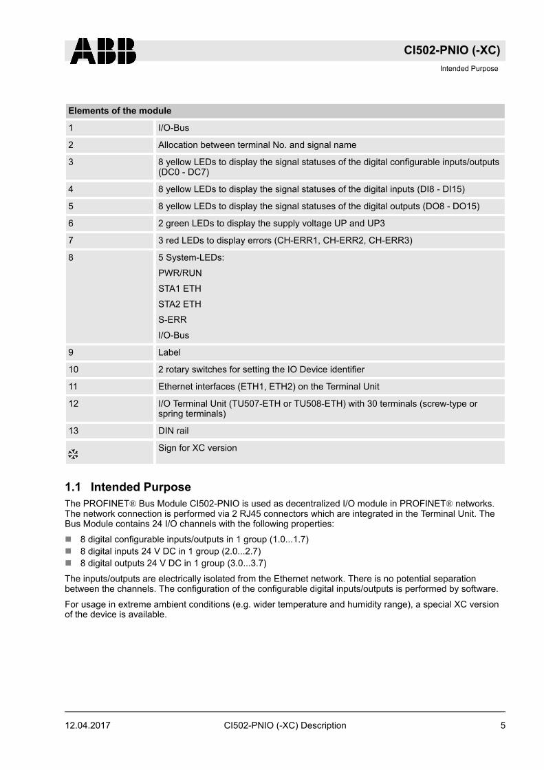
Elements of the module
1 I/O-Bus
2 Allocation between terminal No. and signal name
3 8 yellow LEDs to display the signal statuses of the digital configurable inputs/outputs(DC0 - DC7)
4 8 yellow LEDs to display the signal statuses of the digital inputs (DI8 - DI15)
5 8 yellow LEDs to display the signal statuses of the digital outputs (DO8 - DO15)
6 2 green LEDs to display the supply voltage UP and UP3
7 3 red LEDs to display errors (CH-ERR1, CH-ERR2, CH-ERR3)
8 5 System-LEDs:
PWR/RUN
STA1 ETH
STA2 ETH
S-ERR
I/O-Bus
9 Label
10 2 rotary switches for setting the IO Device identifier
11 Ethernet interfaces (ETH1, ETH2) on the Terminal Unit
12 I/O Terminal Unit (TU507-ETH or TU508-ETH) with 30 terminals (screw-type orspring terminals)
13 DIN rail
Sign for XC version
1.1 Intended PurposeThe PROFINET® Bus Module CI502-PNIO is used as decentralized I/O module in PROFINET® networks.The network connection is performed via 2 RJ45 connectors which are integrated in the Terminal Unit. TheBus Module contains 24 I/O channels with the following properties:
n 8 digital configurable inputs/outputs in 1 group (1.0...1.7)n 8 digital inputs 24 V DC in 1 group (2.0...2.7)n 8 digital outputs 24 V DC in 1 group (3.0...3.7)
The inputs/outputs are electrically isolated from the Ethernet network. There is no potential separationbetween the channels. The configuration of the configurable digital inputs/outputs is performed by software.
For usage in extreme ambient conditions (e.g. wider temperature and humidity range), a special XC versionof the device is available.
CI502-PNIO (-XC)Intended Purpose
12.04.2017 CI502-PNIO (-XC) Description 5

1.2 FunctionalityInterface Ethernet
Protocol PROFINET® IO RT
Power supply From the process supply voltage UP
Supply of the electronic circuitry of the I/O expan-sion modules attached
Through the expansion bus interface (I/O-Bus)
Rotary switches For setting the IO Device identifier for configurationpurposes (00h to FFh)
Configurable digital inputs/outputs 8 (configurable via software)
Digital inputs 8 (24 V DC; delay time configurable via software)
Digital outputs 8 (24 V DC, 0.5 A max.)
LED displays For system displays, signal statuses, errors andpower supply
External supply voltage Via terminals ZP, UP and UP3 (process supplyvoltage 24 V DC)
Effect of incorrect input terminal connection Wrong or no signal detected, no damage up to 35V
1.3 Electrical ConnectionThe Ethernet Bus Module CI502-PNIO is plugged on the I/O Terminal Unit TU507-ETH or TU508-ETH. Prop-erly seat the module and press until it locks in place. The Terminal Unit is mounted on a DIN rail or with 2screws plus the additional accessory for wall mounting (TA526).
The electrical connection of the I/O channels is carried out using the 30 terminals of the I/O Terminal Unit.I/O modules can be replaced without re-wiring the Terminal Units.
For a detailed description of the mounting, disassembly and electrical connection of the module,please refer to the System Assembly, Construction and Connection chapter.
The terminals 1.8 and 2.8 as well as 1.9, 2.9 and 3.9 are electrically interconnected within the Terminal Unitand have always the same assignment, independent of the inserted module:
Terminals 1.8 and 2.8: Process supply voltage UP = +24 V DC
Terminal 3.8: Process supply voltage UP3 = +24 V DC
Terminals 1.9, 2.9 and 3.9: Process supply voltage ZP = 0 VThe assignment of the other terminals:
With a separate UP3 power supply, the digital outputs can be switched off externally. This way, anemergency-off functionality can be realized.
CI502-PNIO (-XC)Electrical Connection
12.04.2017CI502-PNIO (-XC) Description6

Do not connect any voltages externally to digital outputs!
This ist not intended usage.
Reason: Externally voltages at one or more terminals DC0..DC7 or DO0..DO7 may cause that otherdigital outputs are supplied through that voltage instead of voltage UP3 (reverse voltage).
This is also possible, if DC channels are used as inputs. For this, the source for the input signalsshould be the impressed UP3 of the device.
This limitation does not apply for the input channels DI0..DI7.
CAUTION!
Risk of malfunction by not intended usage!If the function cut off of the digital outputs should be used by deactivation of the supply voltage UP3,be sure that no external voltage is conncted at the outputs DO0..DO7 and DC0..DC7.
The assignment of the other terminals:
Terminal Signal Meaning
1.0 DC0 Signal of the configurable digital input/output DC0
1.1 DC1 Signal of the configurable digital input/output DC1
1.2 DC2 Signal of the configurable digital input/output DC2
1.3 DC3 Signal of the configurable digital input/output DC3
1.4 DC4 Signal of the configurable digital input/output DC4
1.5 DC5 Signal of the configurable digital input/output DC5
1.6 DC6 Signal of the configurable digital input/output DC6
1.7 DC7 Signal of the configurable digital input/output DC7
1.8 UP Process voltage UP (24 V DC)
1.9 ZP Process voltage ZP (0 V DC)
2.0 DI8 Signal of the digital input DI8
2.1 DI9 Signal of the digital input DI9
2.2 DI10 Signal of the digital input DI10
2.3 DI11 Signal of the digital input DI11
2.4 DI12 Signal of the digital input DI12
2.5 DI13 Signal of the digital input DI13
2.6 DI14 Signal of the digital input DI14
2.7 DI15 Signal of the digital input DI15
CI502-PNIO (-XC)Electrical Connection
12.04.2017 CI502-PNIO (-XC) Description 7

Terminal Signal Meaning
2.8 UP Process voltage UP (24 V DC)
2.9 ZP Process voltage ZP (0 V DC)
3.0 DO8 Signal of the digital output DO8
3.1 DO9 Signal of the digital output DO9
3.2 DO10 Signal of the digital output DO10
3.3 DO11 Signal of the digital output DO11
3.4 DO12 Signal of the digital output DO12
3.5 DO13 Signal of the digital output DO13
3.6 DO14 Signal of the digital output DO14
3.7 DO15 Signal of the digital output DO15
3.8 UP3 Process voltage UP3 (24 V DC)
3.9 ZP Process voltage ZP (0 V DC)
WARNING!
Removal/Insertion under powerThe devices are not designed for removal or insertion under power. Because of unforeseeable conse-quences, it is not allowed to plug or unplug devices with the power being ON.
Make sure that all voltage sources (supply and process voltage) are switched off before you
– connect or disconnect any signal or terminal block– remove, mount or replace a module.
Disconnecting any powered devices while energized in a hazardous location could result in an electricarc, which could create a flammable ignition resulting in fire or explosion.
Make sure that power is removed and that the area has been thoroughly checked to ensure that flam-mable materials are not present prior to proceeding.
The devices must not be opened when in operation. The same applies to the network interfaces.
NOTICE!
Risk of damaging the PLC modules!Overvoltages and short circuits might damage the PLC modules.
– Make sure that all voltage sources (supply and process voltage) are switched off before you beginwith operations at the system.
– Never connect any voltages or signals to reserved terminals (marked with ---). Reserved terminalsmay carry internal voltages.
The following figure shows the electrical connection of the Ethernet Bus Module CI502-PNIO.
CI502-PNIO (-XC)Electrical Connection
12.04.2017CI502-PNIO (-XC) Description8

Fig. 2: Connection of the Bus Module CI502-PNIO
Further information is provided in the System Technology chapter PROFINET.
1.3.1 Connection of the digital inputsThe following figure shows the electrical connection of the digital input DI8. Proceed with the digital inputsDI9 to DI15 in the same way.
CI502-PNIO (-XC)Electrical Connection > Connection of the digital inputs
12.04.2017 CI502-PNIO (-XC) Description 9

Fig. 3: Connection of the digital inputs to the module CI502-PNIO
The meaning of the LEDs is described in Displays Ä Chapter 1.8.1 “Status LEDs” on page 20.
1.3.2 Connection of the digital outputsThe following figure shows the electrical connection of the digital output DO8. Proceed with the digital out-puts DO9 - DO15 in the same way.
CI502-PNIO (-XC)Electrical Connection > Connection of the digital outputs
12.04.2017CI502-PNIO (-XC) Description10

Fig. 4: Connection of configurable digital inputs/outputs to the module CI502-PNIO
The meaning of the LEDs is described in Displays Ä Chapter 1.8.1 “Status LEDs” on page 20.
1.3.3 Connection of the configurable digital inputs/outputsThe following figure shows the electrical connection of the configurable digital input/output DC0 and DC1.DC0 is connected as an input and DC1 is connected as an output. Proceed with the configurable digitalinputs/outputs DC2 to DC7 in the same way.
CAUTION!
If a DC channel is used as input, the source for the input signals should be the impressed UP3 of thedevice Ä Chapter 1.3 “Electrical Connection” on page 6.
CI502-PNIO (-XC)Electrical Connection > Connection of the configurable digital inputs/outputs
12.04.2017 CI502-PNIO (-XC) Description 11

1.0DC01.1DC11.2DC21.3DC31.4DC41.5DC51.6DC61.7DC71.8UP1.9ZP
-+
24 V DC
2.4
DI14
2.0DI82.1DI92.2DI102.3DI11
DI122.5DI132.6
2.7DI152.8UP2.9ZP
3.0DO83.1DO93.2DO103.3DO113.4DO123.5DO133.6DO143.7DO153.8UP33.9ZP
Fig. 5: Connection of configurable digital inputs/outputs to the module CI502-PNIO
The meaning of the LEDs is described in Displays Ä Chapter 1.8.1 “Status LEDs” on page 20.
1.3.4 Assignment of the Ethernet PortsThe Terminal Unit for the Communication Interface Module provides two Ethernet interfaces with the fol-lowing pin assignment:
Table 1: Pin assignment RJ45 jack:1 TxD+ Transmit data +
2 TxD- Transmit data -
3 RxD+ Receive data +
4 NC not used
5 NC not used
6 RxD- Receive data -
7 NC not used
8 NC not used
Shield Cable shield Functional earth
CI502-PNIO (-XC)Electrical Connection > Assignment of the Ethernet Ports
12.04.2017CI502-PNIO (-XC) Description12
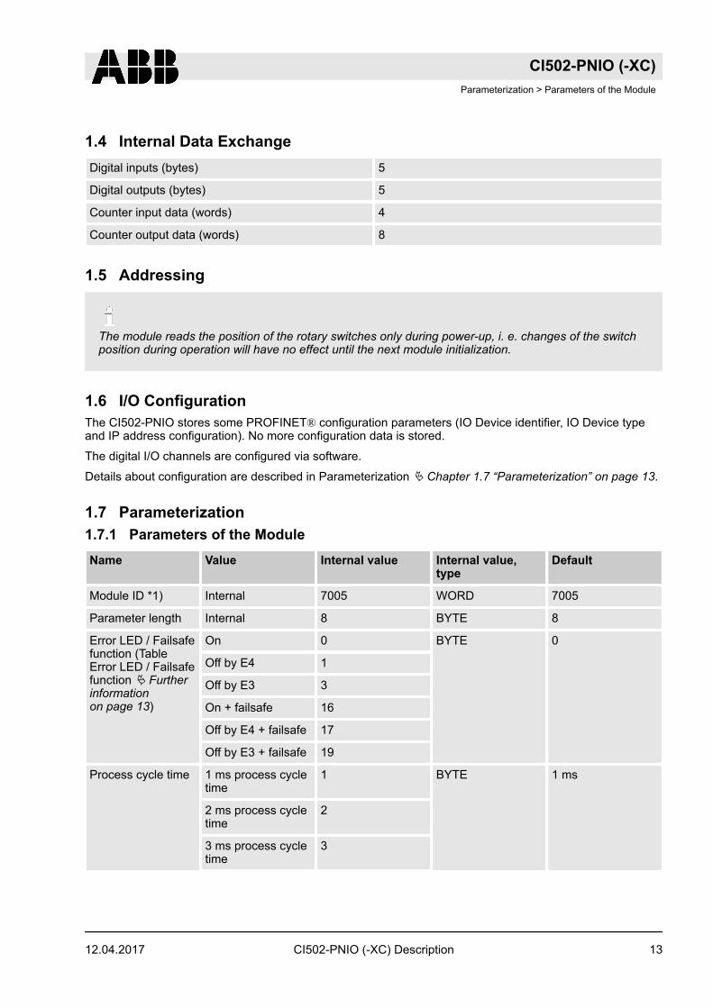
1.4 Internal Data ExchangeDigital inputs (bytes) 5
Digital outputs (bytes) 5
Counter input data (words) 4
Counter output data (words) 8
1.5 Addressing
The module reads the position of the rotary switches only during power-up, i. e. changes of the switchposition during operation will have no effect until the next module initialization.
1.6 I/O ConfigurationThe CI502-PNIO stores some PROFINET® configuration parameters (IO Device identifier, IO Device typeand IP address configuration). No more configuration data is stored.
The digital I/O channels are configured via software.
Details about configuration are described in Parameterization Ä Chapter 1.7 “Parameterization” on page 13.
1.7 Parameterization1.7.1 Parameters of the ModuleName Value Internal value Internal value,
typeDefault
Module ID *1) Internal 7005 WORD 7005
Parameter length Internal 8 BYTE 8
Error LED / Failsafefunction (TableError LED / Failsafefunction Ä Furtherinformationon page 13)
On 0 BYTE 0
Off by E4 1
Off by E3 3
On + failsafe 16
Off by E4 + failsafe 17
Off by E3 + failsafe 19
Process cycle time 1 ms process cycletime
1 BYTE 1 ms
2 ms process cycletime
2
3 ms process cycletime
3
CI502-PNIO (-XC)Parameterization > Parameters of the Module
12.04.2017 CI502-PNIO (-XC) Description 13

Name Value Internal value Internal value,type
Default
4 ms process cycletime
4
5 ms process cycletime
5
6 ms process cycletime
6
7 ms process cycletime
7
8 ms process cycletime
8
9 ms process cycletime
9
10 ms processcycle time
10
11 ms processcycle time
11
12 ms processcycle time
12
13 ms processcycle time
13
14 ms processcycle time
14
15 ms processcycle time
15
16 ms processcycle time
16
Check supply off
on
0
1
BYTE 1
Fast counter 0
:
10 2*)
0
:
10
BYTE 0
*1) With a faulty ID, the module reports a "parameter error" and does not perform cyclic process data trans-mission.
*2) Counter operating modes
CI502-PNIO (-XC)Parameterization > Parameters of the Module
12.04.2017CI502-PNIO (-XC) Description14

Table 2: Table Error LED / Failsafe functionSetting Meaning
On Error-LED (S-ERR) lights up at errors of all errorclasses, Failsafe-mode off
Off by E4 Error LED (S-ERR) lights up at errors of errorclasses E1, E2 and E3, Failsafe-mode off
Off by E3 Error LED (S-ERR) lights up at errors of errorclasses E1 and E2, Failsafe-mode off
On + Failsafe Error-LED (S-ERR) lights up at errors of all errorclasses, Failsafe-mode on*
Off by E4 + Failsafe Error LED (S-ERR) lights up at errors of errorclasses E1, E2 and E3, Failsafe-mode on*
Off by E3 + Failsafe Error LED (S-ERR) lights up at errors of errorclasses E1 and E2, Failsafe-mode on*
*) The parameter Behaviour DO at comm. error is only analyzed if the Failsafe-mode is ON.
1.7.2 Group parameters for the digital partName Value Internal value Internal value,
typeDefault
Input delay 0.1 ms
1 ms
8 ms
32 ms
0
1
2
3
BYTE 0.1 ms
0x00
Detect short circuitat outputs
Off
On
0
1
BYTE On
0x01
Behaviour DO atcomm. error *)
Off
Last value
Last value 5 sec
Last value 10 sec
Substitute value
Substitute value 5sec
Substitute value 10sec
0
1
6
11
2
7
12
BYTE Off
0x00
Substitute value atoutput
0 ... 65535 0000h ... FFFFh WORD 0
0x0000
Preventive voltagefeedback moni-toring for DC0..DC7**)
Off
On
0
1
BYTE Off
0x00
CI502-PNIO (-XC)Parameterization > Group parameters for the digital part
12.04.2017 CI502-PNIO (-XC) Description 15

Name Value Internal value Internal value,type
Default
Detect voltageoverflow at outputs***)
Off
On
0
1
BYTE Off
0x00
*) The parameter Behaviour DO at comm. error is apply to DC and DO channels and only analyzed if theFailsafe-mode is ON.
**) The status "externally voltage detected" appears, if the output of a channel DC0..DC7 should beswitched on while an externally voltage is connected. In this case the start up is disabled, as long as theexternally voltage is connected. The monitoring of this state and the resulting diagnosis message can bedisabled by setting the parameters to "OFF".
***) The error status "voltage overflow at outputs" appears, if externally voltage at digital outputs DC0..DC7and accordingly DO0..DO7 has exceeded the process supply voltage UP3 Ä Chapter 1.3 “Electrical Con-nection” on page 6 (see description in section). The according diagnosis message "Voltage overflow onoutputs " can be disabled by setting the parameters on "OFF". This parameter should only be disabled inexceptional cases for voltage overflow may produce reverse voltage.
1.8 DiagnosisStructure of the Diagnosis Block via PNIO_DEV_ALARM Function Block.
Byte Number Description Possible Values
1 Diagnosis Byte, slot number 31 = CI502-PNIO (e. g. error at integrated 8 DI /8 DO)
1 = 1st connected S500 I/O Module
...
10 = 10th connected S500 I/O Module
2 Diagnosis Byte, modulenumber
According to the I/O Bus specification passed onby modules to the fieldbus master
3 Diagnosis Byte, channel According to the I/O Bus specification passed onby modules to the fieldbus master
4 Diagnosis Byte, error code According to the I/O Bus specification
Bit 7 and bit 6, coded error class
0 = E1
1 = E2
2 = E3
3 = E4
Bit 0 to Bit 5, coded error description
5 Diagnosis Byte, flags According to the I/O Bus specification
Bit 7: 1 = coming error
Bit 6: 1 = leaving error
CI502-PNIO (-XC)Diagnosis
12.04.2017CI502-PNIO (-XC) Description16

In cases of short circuit or overload, the digital outputs are turned off. The modules performs reactivationautomatically. Thus an acknowledgement of the errors is not necessary. The error message is stored via theLED.
E1..E4 d1 d2 d3 d4 Identifier000..063
AC500-Display
<− Display in
Class Comp Dev Mod Ch Err PS501PLCBrowser
Byte 4Bit 6..7
- Byte 1 Byte 2 Byte 3 Byte 4Bit 0..5
PNIOdiag-nosisblock
Class Interface Device Module Channel Error-Identifier
Error message Remedy
*1) *2) *3)
Module errors
3 - 31 31 31 19 Checksum error in theI/O module
ReplaceI/Omodule
3 - 31 31 31 3 Timeout in the I/Omodule
3 - 31 31 31 40 Different hard-/firm-ware versions in themodule
3 - 31 31 31 43 Internal error in themodule
3 - 31 31 31 36 Internal dataexchange failure
3 - 31 31 31 9 Overflow diagnosisbuffer
Restart
3 - 31 31 31 26 Parameter error CheckMaster
3 - 31 31 31 11 Process voltage UPtoo low
Checkprocesssupplyvoltage
3 - 31 31 31 45 Process voltage UPgone
Checkprocesssupplyvoltage
3 - 31/1...10 31 31 17 No communicationwith I/O device
ReplaceI/Omodule
CI502-PNIO (-XC)Diagnosis
12.04.2017 CI502-PNIO (-XC) Description 17

E1..E4 d1 d2 d3 d4 Identifier000..063
AC500-Display
<− Display in
Class Comp Dev Mod Ch Err PS501PLCBrowser
Byte 4Bit 6..7
- Byte 1 Byte 2 Byte 3 Byte 4Bit 0..5
PNIOdiag-nosisblock
Class Interface Device Module Channel Error-Identifier
Error message Remedy
*1) *2) *3)
3 - 1...10 31 31 32 Wrong I/O device typeon socket
ReplaceI/Omodule /Checkconfigura-tion
4 - 1...10 31 31 31 At least one moduledoes not support fail-safe function
Checkmodulesandparame-terization
4 1...6 255 2 0 45 The connected Com-munication Modulehas no connection tothe network
Checkcabeling
4 - 31 31 31 45 Process voltage UP3too low
Checkprocessvoltage
4 - 31 31 31 46 Reverse voltage fromdigital outputsDO0..DO7 to UP3 *4)
Checkterminals
4 - 31/1...10 31 31 34 No response duringinitialization of the I/Omodule
ReplaceI/Omodule
4 - 31 31 31 11 Process voltage UP3too low
Checkprocesssupplyvoltage
4 - 31 31 31 45 Process voltage UP3gone
Checkprocesssupplyvoltage
CI502-PNIO (-XC)Diagnosis
12.04.2017CI502-PNIO (-XC) Description18

E1..E4 d1 d2 d3 d4 Identifier000..063
AC500-Display
<− Display in
Class Comp Dev Mod Ch Err PS501PLCBrowser
Byte 4Bit 6..7
- Byte 1 Byte 2 Byte 3 Byte 4Bit 0..5
PNIOdiag-nosisblock
Class Interface Device Module Channel Error-Identifier
Error message Remedy
*1) *2) *3)
4 - 31 31 31 10 Voltage overflow atoutputs (above UP3level) *5)
Checkterminals/checkprocesssupplyvoltage
Channel error digital
4 - 31 2 8..15 46 Externally voltagedetected at digitaloutput DO0..DO7 *6)
Checkterminals
4 - 31 4 0...7 46 Externally voltagedetected at digitaloutput DC0..DC7 *6)
Checkterminals
4 - 31 2 0...7 47 Short circuit at digitaloutput *7)
Checkterminals
*Remarks:
1) In AC500 the following interface identifier applies:
"-" = Diagnosis via bus-specific function blocks; 0 ... 4 or 10 = Position of the Communica-tion Module;14 = I/O-Bus; 31 = Module itself
The identifier is not contained in the CI502-PNIO diagnosis block.
2) With "Device" the following allocation applies: 31 = Module itself, 1..10 = Expansion module
3) With "Module" the following allocation applies dependent of the master:
Module error: 31 = Module itself
Channel error: Module type (1 = AI, 2 = DO, 3 = AO)
4) This message appears, if externally voltages at one or more terminals DC0..DC7 oderDO0..DO7 cause that other digital outputs are supplied through that voltage (voltage feed-back, see description in Electrical Connection Ä Chapter 1.3 “Electrical Connection”on page 6. All outputs of the apply digital output groups will be turned off for 5 seconds. Thediagnosis message appears for the whole output group.
CI502-PNIO (-XC)Diagnosis
12.04.2017 CI502-PNIO (-XC) Description 19

5) The voltage at digital outputs DC0..DC7 and accordingly DO0..DO7 has exceeded theprocess supply voltage UP3 Ä Chapter 1.3 “Electrical Connection” on page 6. Diagnosismessage appears for the whole module.
6) This message appears, if the output of a channel DC0..DC7 or DO0..DO7 should beswitched on while an externally voltage is connected. In this case the start up is disabled, aslong as the externally voltage is connected. Otherwise this could produce reverse voltagefrom this output to other digital outputs. This diagnosis message appears per channel.
7) Short circuit: After a detected short circuit, the output is deactivated for 2000ms. Then a newstart up will be executed. This diagnosis message appears per channel.
1.8.1 Status LEDsThe LEDs are located at the front of module. There are 2 different groups:
n The 5 system LEDs (PWR, STA1 ETH, STA2 ETH, S-ERR and I/O-Bus) show the operation status of themodule and display possible errors.
n The 29 process LEDs (UP, UP3, inputs, outputs, CH-ERR1 to CH-ERR3) show the process supplyvoltage and the statuses of the inputs and outputs and display possible errors.
Table 3: Status of the 5 System-LEDsLED Color OFF ON Flashing
PWR/RUN Green Process supplyvoltage missing
Internal supplyvoltage OK, moduleready for communi-cation with IO Con-troller
Start-up / preparingcommunication
Yellow --- --- ---
STA1 ETH(System-LED "BF")
Green --- Device configured,cyclic dataexchange running
---
Red --- --- Device is not con-figured
STA2 ETH(System-LED "SF")
Green --- --- Got identificationrequest from IOController
Red No system error System error (col-lective error)
---
S-ERR Red No error Internal error --
I/O-Bus Green No expansion mod-ules connected orcommunicationerror
Expansion modulesconnected andoperational
---
ETH1 Green No connection atEthernet interface
Connected toEthernet interface
---
Yellow --- Device is transmit-ting telegrams
Device is transmit-ting telegrams
CI502-PNIO (-XC)Diagnosis > Status LEDs
12.04.2017CI502-PNIO (-XC) Description20
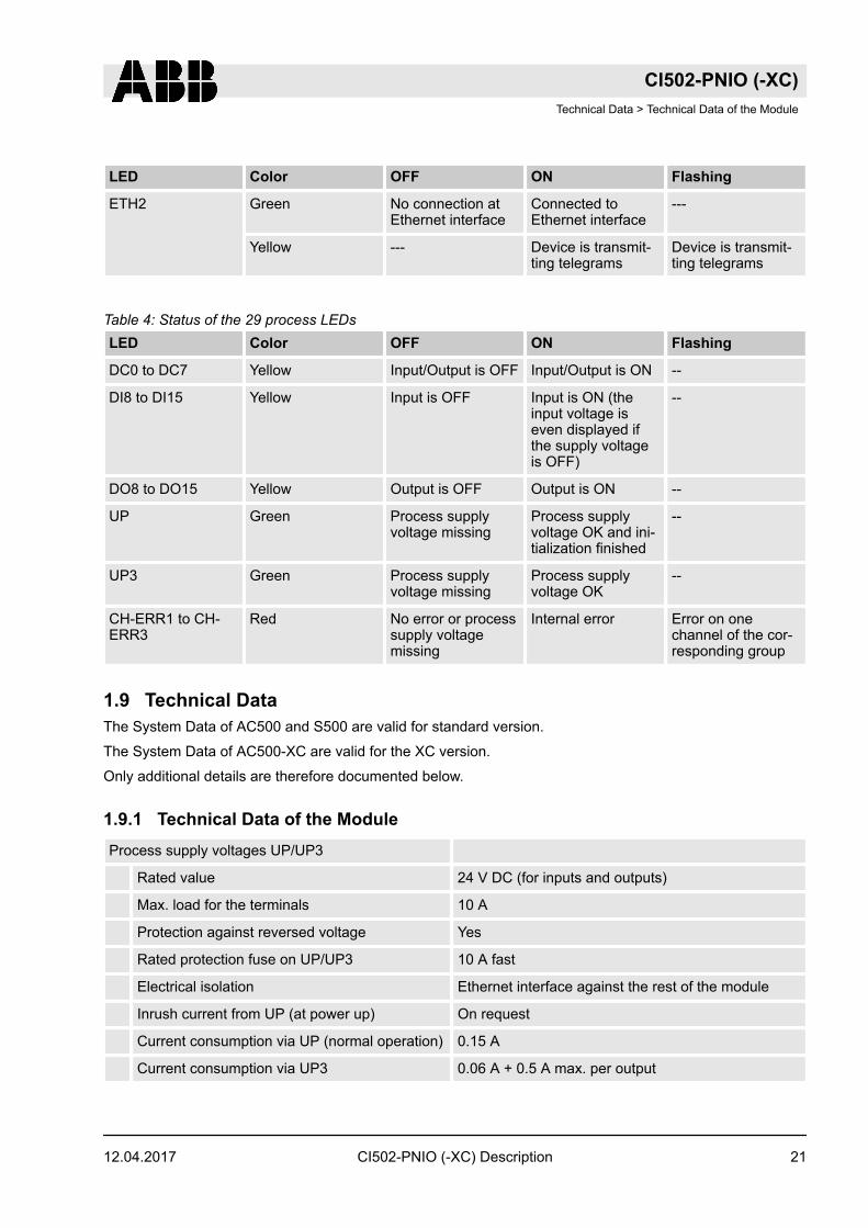
LED Color OFF ON Flashing
ETH2 Green No connection atEthernet interface
Connected toEthernet interface
---
Yellow --- Device is transmit-ting telegrams
Device is transmit-ting telegrams
Table 4: Status of the 29 process LEDsLED Color OFF ON Flashing
DC0 to DC7 Yellow Input/Output is OFF Input/Output is ON --
DI8 to DI15 Yellow Input is OFF Input is ON (theinput voltage iseven displayed ifthe supply voltageis OFF)
--
DO8 to DO15 Yellow Output is OFF Output is ON --
UP Green Process supplyvoltage missing
Process supplyvoltage OK and ini-tialization finished
--
UP3 Green Process supplyvoltage missing
Process supplyvoltage OK
--
CH-ERR1 to CH-ERR3
Red No error or processsupply voltagemissing
Internal error Error on onechannel of the cor-responding group
1.9 Technical DataThe System Data of AC500 and S500 are valid for standard version.
The System Data of AC500-XC are valid for the XC version.
Only additional details are therefore documented below.
1.9.1 Technical Data of the ModuleProcess supply voltages UP/UP3
Rated value 24 V DC (for inputs and outputs)
Max. load for the terminals 10 A
Protection against reversed voltage Yes
Rated protection fuse on UP/UP3 10 A fast
Electrical isolation Ethernet interface against the rest of the module
Inrush current from UP (at power up) On request
Current consumption via UP (normal operation) 0.15 A
Current consumption via UP3 0.06 A + 0.5 A max. per output
CI502-PNIO (-XC)Technical Data > Technical Data of the Module
12.04.2017 CI502-PNIO (-XC) Description 21

Connections Terminals 1.8 and 2.8 for +24 V (UP)
Terminal 3.8 for +24 V (UP3)
Terminals 1.9, 2.9 and 3.9 for 0 V (ZP)
Max. power dissipation within the module 6 W
Number of digital inputs 8
Number of digital outputs 8
Number of configurable digital inputs/outputs 8
Input data length 12 bytes
Output data length 20 bytes
Reference potential for all digital inputs and outputs Minus pole of the supply voltage, signal name ZP
Setting of the IO Device identifier With 2 rotary switches at the front side of the module
Diagnosis See Diagnosis and Displays Ä Chapter 1.8 “Diag-nosis” on page 16
Operation and error displays 34 LEDs (totally)
Weight (without Terminal Unit) Ca. 125 g
Mounting position Horizontal or vertical with derating (output loadreduced to 50 % at 40°C per group)
Extended ambient temperature (XC version) >60 °C on request
Cooling The natural convection cooling must not be hinderedby cable ducts or other parts in the switch-gear cab-inet.
NOTICE!
Attention:All I/O channels (digital and analog) are protected against reverse polarity, reverse supply, short circuitand continuous overvoltage up to 30 V DC.
Effects of multiple overloads on isolated multi-channel modulesNo effect, as every channel is protected individually by an internal smart high-side switch.
Bus connection 2 x RJ45
Switch Integrated
Technology Hilscher netX100
Transfer rate 10/100 MBit/s (full-duplex)
Transfer method According to Ethernet II, IEE802.3
Expandability Max. 10 S500 I/O modules
CI502-PNIO (-XC)Technical Data > Technical Data of the Module
12.04.2017CI502-PNIO (-XC) Description22

Adjusting elements 2 rotary switches for generation of an explicit name
Supported protocols RTC - real-time cyclic protocol, class 1 *
RTA - real-time acyclic protocol
DCP - discovery and configuration protocol
CL-RPC - connectionless remote procedure Call
LLDP - link layer discovery protocol
Acyclic services PNIO read / write sequence (max. 1024 bytes pertelegram)
Process-Alarm service
Supported alarm types Process Alarm, Diagnostic Alarm, Return of Sub-Module, Plug Alarm, Pull Alarm
Min. bus cycle 1 ms
Conformance Class CC A
Protective functions (according to IEC61131-3) Protected against:
- short circuit
- reverse supply
- overvoltage
- reverse polarity
Electrical isolation from the rest of the module
* Priorization with the aid of VLAN-ID including priority level
1.9.2 Technical Data of the Digital InputsNumber of channels per module 8
Distribution of the channels into groups 1 group of 8 channels
Terminals of the channels DI0 to DI7 Terminals 2.0 to 2.7
Reference potential for all inputs Terminals 1.9...3.9 (Minus pole of the supply voltage,signal name ZP)
Indication of the input signals 1 yellow LED per channel, the LED is ON when theinput signal is high (signal 1)
Input type (according EN 61131-2) Type 1
Input delay (0->1 or 1->0) Typ. 0.1 ms, configurable from 0.1...32 ms
Input signal voltage 24 V DC
Signal 0 -3 V...+5 V
Undefined Signal > +5 V...< +15 V
Signal 1 +15 V...+30 V
Ripple with signal 0 Within -3 V...+5 V
CI502-PNIO (-XC)Technical Data > Technical Data of the Digital Inputs
12.04.2017 CI502-PNIO (-XC) Description 23

Ripple with signal 1 Within +15 V...+30 V
Input current per channel
Input voltage +24 V Typ. 5 mA
Input voltage +5 V > 1 mA
Input voltage +15 V > 2 mA
Input voltage +30 V < 8 mA
Max. cable length
Shielded 1000 m
Unshielded 600 m
1.9.3 Technical Data of the Digital OutputsNumber of channels per module 8
Distribution of the channels into groups 1 group of 8 channels
Terminals of the channels DO0 to DO7 Terminals 3.0 to 3.7
Reference potential for all outputs Terminals 1.9...3.9 (minus pole of the supply voltage,signal name ZP)
Common power supply voltage For all outputs terminal 3.8 (plus pole of the supplyvoltage, signal name UP3)
Output voltage for signal 1 UP3 (-0,8 V)
Output delay (0->1 or 1->0) On request
Output current
Rated value per channel 500 mA at UP3 = 24 V
Max. value (all channels together) 4 A
Leakage current with signal 0 < 0.5 mA
Fuse for UP3 10 A fast
Demagnetization with inductive DC load Via internal varistors (see figure below this table)
Output switching frequency
With resistive load On request
With inductive loads Max. 0.5 Hz
With lamp loads 11 Hz max. at 5 W max.
Short-circuit proof / overload proof Yes
Overload message (I > 0.7 A) Yes, after ca. 100 ms
Output current limitation Yes, automatic reactivation after short-circuit/over-load
Resistance to feedback against 24V signals Yes (software-controlled supervision)
CI502-PNIO (-XC)Technical Data > Technical Data of the Digital Outputs
12.04.2017CI502-PNIO (-XC) Description24

Max. cable length
Shielded 1000 m
Unshielded 600 m
The following drawing shows the circuitry of a digital input/output with the varistors for demagnetization wheninductive loads are switched off.
2
1
UPx (+24 V)
ZPx (0 V)
Fig. 6: Digital input/output (circuit diagram)
1 Digital Output2 Varistors for demagnetization when inductive loads are turned off
1.9.4 Technical Data of the Configurable Digital Inputs/OutputsEach of the configurable I/O channels is defined as input or output by the user program. This is done byinterrogating or allocating the corresponding channel.
Number of channels per module 8 inputs/outputs (with transistors)
Distribution of the channels into groups 1 group for 8 channels
If the channels are used as inputs
Channels DC0...DC07 Terminals 1.0...1.7
If the channels are used as outputs
Channels DC0...DC07 Terminals 1.0...1.7
Indication of the input/output signals 1 yellow LED per channel, the LED is ON when theinput/output signal is high (signal 1)
Electrical isolation From the Ethernet network
1.9.4.1 Technical Data of the Digital Inputs/Outputs if used as Inputs
Number of channels per module 8
Distribution of the channels into groups 1 group of 8 channels
Terminals of the channels DC0 to DC7 Terminals 1.0 to 1.7
Reference potential for all inputs Terminals 1.9...3.9 (Minus pole of the supply voltage,signal name ZP)
CI502-PNIO (-XC)Technical Data > Technical Data of the Configurable Digital Inputs/Outputs
12.04.2017 CI502-PNIO (-XC) Description 25
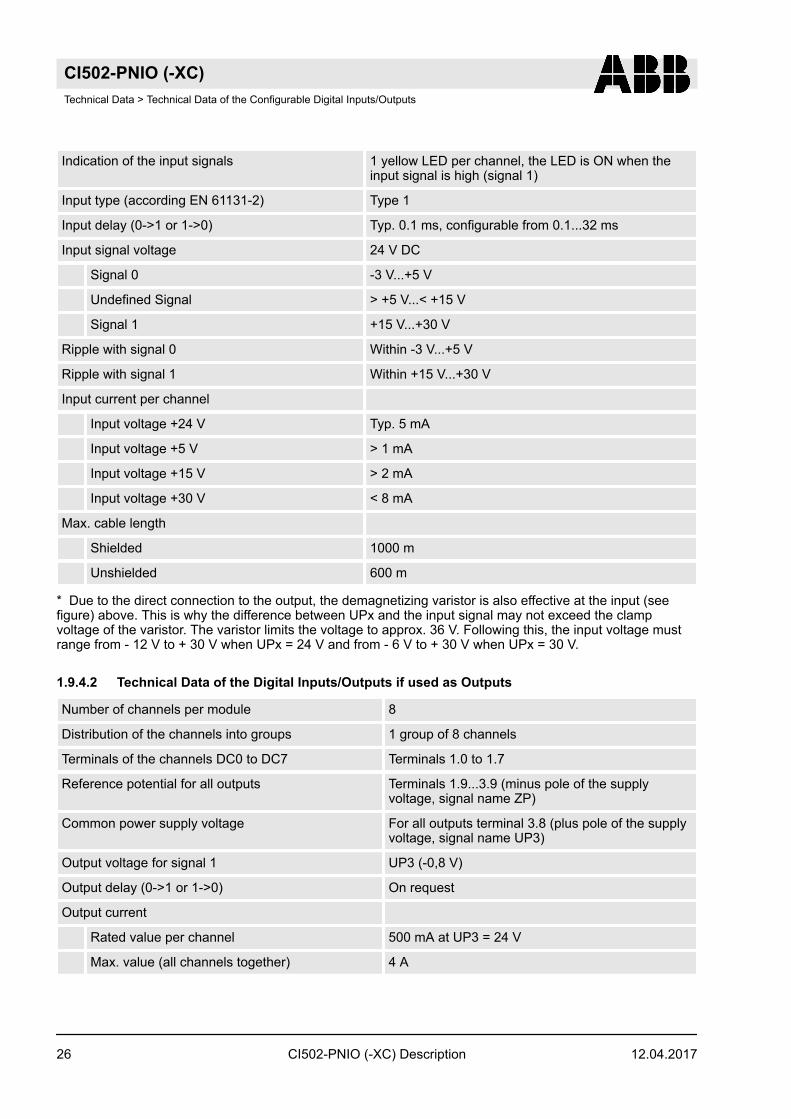
Indication of the input signals 1 yellow LED per channel, the LED is ON when theinput signal is high (signal 1)
Input type (according EN 61131-2) Type 1
Input delay (0->1 or 1->0) Typ. 0.1 ms, configurable from 0.1...32 ms
Input signal voltage 24 V DC
Signal 0 -3 V...+5 V
Undefined Signal > +5 V...< +15 V
Signal 1 +15 V...+30 V
Ripple with signal 0 Within -3 V...+5 V
Ripple with signal 1 Within +15 V...+30 V
Input current per channel
Input voltage +24 V Typ. 5 mA
Input voltage +5 V > 1 mA
Input voltage +15 V > 2 mA
Input voltage +30 V < 8 mA
Max. cable length
Shielded 1000 m
Unshielded 600 m
* Due to the direct connection to the output, the demagnetizing varistor is also effective at the input (seefigure) above. This is why the difference between UPx and the input signal may not exceed the clampvoltage of the varistor. The varistor limits the voltage to approx. 36 V. Following this, the input voltage mustrange from - 12 V to + 30 V when UPx = 24 V and from - 6 V to + 30 V when UPx = 30 V.
1.9.4.2 Technical Data of the Digital Inputs/Outputs if used as Outputs
Number of channels per module 8
Distribution of the channels into groups 1 group of 8 channels
Terminals of the channels DC0 to DC7 Terminals 1.0 to 1.7
Reference potential for all outputs Terminals 1.9...3.9 (minus pole of the supplyvoltage, signal name ZP)
Common power supply voltage For all outputs terminal 3.8 (plus pole of the supplyvoltage, signal name UP3)
Output voltage for signal 1 UP3 (-0,8 V)
Output delay (0->1 or 1->0) On request
Output current
Rated value per channel 500 mA at UP3 = 24 V
Max. value (all channels together) 4 A
CI502-PNIO (-XC)Technical Data > Technical Data of the Configurable Digital Inputs/Outputs
12.04.2017CI502-PNIO (-XC) Description26

Leakage current with signal 0 < 0.5 mA
Fuse for UP3 10 A fast
Demagnetization with inductive DC load Via internal varistors (see figure below this table)
Output switching frequency
With resistive load On request
With inductive loads Max. 0.5 Hz
With lamp loads 11 Hz max. at 5 W max.
Short-circuit proof / overload proof Yes
Overload message (I > 0.7 A) Yes, after ca. 100 ms
Output current limitation Yes, automatic reactivation after short-circuit/over-load
Resistance to feedback against 24V signals Yes (software-controlled supervision)
Max. cable length
Shielded 1000 m
Unshielded 600 m
The following drawing shows the circuitry of a digital input/output with the varistors for demagnetization wheninductive loads are switched off.
2
1
UPx (+24 V)
ZPx (0 V)
Fig. 7: Digital input/output (circuit diagram)
1 Digital input/output2 For demagnetization when inductive loads are turned off
Figure:
1.9.5 Technical Data of the Fast CounterUsed inputs Terminal 3.0 (DI0),Terminal 3.1 (DI1)
Used outputs Terminal 4.0 (DO0)
CI502-PNIO (-XC)Technical Data > Technical Data of the Fast Counter
12.04.2017 CI502-PNIO (-XC) Description 27

Counting frequency Depending on operation mode:
Mode 1- 6: max. 200 kHz
Mode 7: max. 50 kHz
Mode 9: max. 35 kHz
Mode 10: max. 20 kHz
Detailed description See Fast Counter
Operating modes See Operating modes
1.10 Ordering DataOrdering No. Scope of delivery
1SAP 220 700 R0001 CI502-PNIO (V3), PROFINET® Bus Module with 8DI, 8 DO and 8 DC
1SAP 420 700 R0001 CI502-PNIO-(V3)-XC, PROFINET® Bus Modulewith 8 DI, 8 DO and 8 DC, XC version
1SAP 214 200 R0001 TU507-ETH, ETH Terminal Unit, screw-type termi-nals
1SAP 214 000 R0001 TU508-ETH, ETH Terminal Unit, spring terminals
1SAP 414 000 R0001 TU508-ETH-XC, ETH Terminal Unit, spring termi-nals, XC version
CI502-PNIO (-XC)Ordering Data
12.04.2017CI502-PNIO (-XC) Description28

2 System Information2.1 PROFINET® Modules2.1.1 Communication Modules and Communication Interface ModulesThe Communication Module CM5xy-PNIO is used as IO Controllers in a PROFINET® network. It is con-nected to the Processor Module via an internal communication bus .
The Communication Interface Modules CI50x-PNIO are the IO devices for PROFINET® RT. The differenceof those devices can be found in their input and output characteristics Comparison.
2.1.2 Device Model of PROFINET® IO DevicesPROFINET® standard defines modules and sub-modules to give structure to IO devices data. These itemsare used in hierarchical order wherein a module may include one or more sub-modules. The input and outputdata of an IO device are located inside these sub-modules. The modules and sub-modules can be identifiedvia ident-numbers (module ident-number and sub module ident-number) and can be assigned to slots andsub slots. Basically 32767 slot indexes and also 32767 sub slot indexes are available to design the devicestructure.
PROFINET® standard defines the following sub-module types which have special meaning and providestandard device functionality. In AC500 PROFINET IO devices the protocol stack defines how these specialsub-modules have to be placed. The sub-modules have to be assigned to module slot 0:
Sub-module type Assigned sub-slot
DAP 1
Interface 32768
Port 1 32769
Port 2 32770
Automation Builder configuration assigns DAP, interface, port 1 and port 2 to desired slot/sub-slots. Thesemodules are inserted automatically in hidden style so they are not visible to the user. It is only required toassign manually the modules/sub-modules needed for providing IO data.
AC500 PROFINET IO devices use module types which support one single sub-module only. This single sub-module is inserted automatically in hidden style so it is not visible to the user. Different types of modules pro-vide different structures of IO data, e.g. single bytes, multiple bytes, words etc. Combining a selection ofmodule types defines a specific structure of IO channels at the device.
The different types of modules are:
Module type Ident number Description
4 Byte input 36864 4 byte input data, to be mapped toIEC output
4 Byte Output 36868 4 byte output data, to be mappedto IEC input
16 Byte Input 36865 16 byte input data, to be mappedto IEC output
16 Byte Output 36869 16 byte output data, to be mappedto IEC input
System InformationPROFINET® Modules > Device Model of PROFINET® IO Devices
12.04.2017 CI502-PNIO (-XC) Description 29

Module type Ident number Description
16 Byte Input Output 36872 16 byte input and 16 byte outputdata
4 Word Input 36866 4 word input data, to be mappedto IEC output
4 Word Output 36870 4 word output data, to be mappedto IEC input
16 Word Input 36867 16 word input data, to be mappedto IEC output
16 Word Output 36871 16 word output data, to bemapped to IEC input
16 Word Input Output 36873 16 word input and 16 word outputdata
16 Byte 16 Word Input Output 36874 16 byte and word input and outputdata
Sub-module ident-numbers are the same as the module ident-numbers. Basically PROFINET® standarddefines the property API to define standard behavior to IO devices. AC500 PROFINET IO devices supportAPI 0 only. Corresponding API setting for protocol stack configuration is set automatically .
2.1.3 Allocation of the Device NameGeneral InformationThere are 2 possibilities for the allocation of the device name of the modules CI50x-PNIO or CM589-PNIO:
n Allocation of the device name via DCP (Engineering Tool needed)n Allocation of the device name via address switches (without Engineering Tool)
For the start-up of PROFINET®, the address information "MAC address" and an unique "device name" issufficient. The allocation of the IP address is performed via the IO Controller automatically during start-up ofthe bus communication.
CAUTION!
Malfunctions due to wrong device name settings!Each device name can only be used once in a network to be explicit.
Make sure that each device has an unique device name.
A maximum of 256 CI5x1-PNIO devices can be used within the same network. The ABB CM579-PNIOPROFINET® Controller can handle up to 128 PROFINET® IO Devices.
Allocation of the Device Name via DCPThe allocation of the device name via DCP is standard for PROFINET® networks. For this possibility of allo-cation, it is absolutely necessary to set both address switches must to "00".
System InformationPROFINET® Modules > Allocation of the Device Name
12.04.2017CI502-PNIO (-XC) Description30

A device name set via DCP will be also present after a restart of the device (is stored permanently).
If the address switches are not set to "00", the device name via DCP is also stored permanently. Butafter a restart, the stored device name is not used.
Allocation of the Device Name via Address SwitchesThe AC500 PROFINET® IO RT Devices (CI50x-PNIO) are equipped with 2 rotary switches to set an explicitname to the IO Devices before commissioning. No engineering tool is needed.
The device gets its name (including the fixed part of the device name) directly from the setting of theswitches (01h...FFh). This name can be used directly within the device configuration.
This name is for example:
ci501-pn-xx
"ci501-pn is the fixed part of the device name and xx represents the position of the rotary switch (0..255d or0..FFh).
2.2 Pin AssignmentTable 5: Pin assignment RJ45 jack:
1 TxD+ Transmit data +
2 TxD- Transmit data -
3 RxD+ Receive data +
4 NC not used
5 NC not used
6 RxD- Receive data -
7 NC not used
8 NC not used
Shield Cable shield Functional earth
For the supported protocols and used Ethernet ports, please refer to the description of AC500 Ethernet Pro-tocols and Ports Ethernet Protocols and Ports.
For a detailed description of the communication via Modbus TCP/IP, please refer to Communication withModbus RTU and Modbus TCP/IP Modbus Communication.
System InformationPin Assignment
12.04.2017 CI502-PNIO (-XC) Description 31

2.3 Wiring2.3.1 Cable TypesA direct connection of two terminal devices is the simplest variant of an Ethernet network. In this case, acrossover cable (also called crossconnect or crosslink cable) has to be used to connect the transmissionlines of the first station to the reception lines of the second station. The following figure shows the wiring of acrossover cable.
12345678 1234567812345678
12345678
Fig. 8: Wiring of a crossover cable
For networks with more than two subscribers, hubs or switches have to be used additionally for distribution.These active devices already have the crossover functionality implemented which allows a direct connectionof the terminal devices using straight-through cables.
12345678 1234567812345678
12345678
Fig. 9: Wiring of a straight-through cable
CAUTION!
Risk of communication faults!When uning inappropriate cables, malfunctions in communication may occur.
Only use network cables of the categories 5 (Cat 5, Cat 5e, Cat 6 or Cat 7) or higher within PRO-FINET® networks.
2.3.2 Cable Length RestrictionsCable Length RestrictionsFor the maximum possible cable lengths within an Ethernet network, various factors have to be taken intoaccount. Twisted pair cables (TP cables) are used as transmission medium for 10 Mbit/s Ethernet (10Base-T) as well as for 100 Mbit/s (Fast) Ethernet (100Base-TX). For a transmission rate of 10 Mbit/s, cables of atleast category 3 (IEA/TIA 568-A-5 Cat3) or class C (according to European standards) are allowed. For fastEthernet with a transmission rate of 100 Mbit/s, cables of category 5 (Cat5) or class D or higher have to beused. The maximum length of a segment, which is the maximum distance between two network compo-nents, is restricted to 100 m due to the electric properties of the cable.
Furthermore, the length restriction for one collision domain has to be observed. A collision domain is thearea within a network which can be affected by a possibly occurring collision (i.e. the area the collision canpropagate over). This, however, only applies if the components operate in half-duplex mode since theCSMA/CD access method is only used in this mode. If the components operate in full-duplex mode, no colli-sions can occur. Reliable operation of the collision detection method is important, which means that it has tobe able to detect possible collisions even for the smallest possible frame size of 64 bytes (512 bits). But thisis only guaranteed if the first bit of the frame arrives at the most distant subscriber within the collision domainbefore the last bit has left the transmitting station. Furthermore, the collision must be able to propagate to
System InformationWiring > Cable Length Restrictions
12.04.2017CI502-PNIO (-XC) Description32

both directions at the same time. Therefore, the maximum distance between two ends must not be longerthan the distance corresponding to the half signal propagation time of 512 bits. Thus, the resulting maximumpossible length of the collision domain is 2000 m for a transmission rate of 10 Mbit/s and 200 m for 100Mbit/s. In addition, the bit delay times caused by the passed network components also have to be consid-ered.
The following table shows the specified properties of the respective cable types per 100 m.
Table 6: Specified cable properties:Parameter 10Base-T [10 MHz] 100Base-TX [100 MHz]
Attenuation [dB / 100m] 10.7 23.2
NEXT [dB / 100m] 23 24
ACR [dB / 100m] N/A 4
Return loss [dB / 100m] 18 10
Wave impedance [Ohms] 100 100
Category 3 or higher 5
Class C or higher D or higher
2.4 PROFINET® Implementation2.4.1 System Start-up BehaviourInitial OperationThe PROFINET® protocol is handled automatically by the PROFINET® Communication Module and thePLC operation system. When the Communication Module is initialized in the proper way and the user appli-cation is running, the Communication Module and the bus become active.
No function blocks are needed for the cyclic process data exchange. The access to the send and receivedata to the according operands range can be performed in the direct way. The access takes place either viaoperands or symbolic variables. Special PROFINET® functions are realised by function blocks of the PRO-FINET® Library.
IP assignmentAfter switching on the power supply of the PLC, the Communication Module assigns the IP-addresses (bymeans of DCP) to the IO devices. The IO device identification is done by the adjusted position of theswitches for setting the device identifier.
InitializationWhen the user application changes into the run mode, the configured IO devices are initialized. At this time,the IO devices get their configuration (and the configuration of possibly connected I/O modules) by the IOcontroller.
Then the configured devices are compared with the available IO devices and I/O modules of the realassembly. If the result of the compare is conformed, the IO devices get their configuration. Otherwise theavailable devices get their configuration and the failure is displayed with the error LEDs of the bus module.The error can also be displayed by using the diagnosis function blocks.
System InformationPROFINET® Implementation > System Start-up Behaviour
12.04.2017 CI502-PNIO (-XC) Description 33
The Communication Module and the IO devices change into the cyclic process data exchange when the con-figuration transfer is completed.
If the configuration is not successful or the cyclic process data exchange between IO controller and IOdevice is broken (e. g. removing of the plug), both participant
n close their communicationn change their status into the initial conditionn try to build up a new connection.
This procedure has no influence on devices where the configuration was successful.
Because of that a replacement of a faulty IO device can be done without restarting the PLC. But you have toconsider that the new device must have the same position of the switches for setting the device identifier likethe replaced one and switch off the power supply of the device you want to replace.
System InformationPROFINET® Implementation > System Start-up Behaviour
12.04.2017CI502-PNIO (-XC) Description34