
IRC5 + PN-SW CI50x-PNIO + S500 IOs Application Example AC500 & IRC5 Fieldbus Connection IRC5 S500...
28
abb Application Example AC500 & IRC5 Fieldbus Connection IRC5 <-> S500 IOs IRC5 with PN-SW as master connected to CI50x-PNIO cluster with S500 IO-Modules IRC5 + PN-SW <-> CI50x-PNIO + S500 IOs
Transcript of IRC5 + PN-SW CI50x-PNIO + S500 IOs Application Example AC500 & IRC5 Fieldbus Connection IRC5 S500...

abb
Application Example AC500 & IRC5
Fieldbus ConnectionIRC5 <-> S500 IOs
IRC5 with PN-SW as masterconnected to CI50x-PNIOcluster with S500 IO-Modules
IRC5 +PN-SW
<->CI50x-PNIO+ S500 IOs

abb ABB Automation Products GmbH 1 Application Example 16.05.2014
Content
1 Disclaimer .................................................................................................................. 3
1.1 For customers domiciled outside Germany/Für Kunden mit Sitz außerhalb Deutschlands ........................................................................ 3
1.2 Nur für Kunden mit Sitz in Deutschland ........................................................................ 3
2 Overview of this manual ........................................................................................... 4
3 Workflow overview .................................................................................................... 5
4 Hardware setup ......................................................................................................... 6
4.1 IRC5 with PROFINET SW stack ...................................................................................... 6
4.2 CI50x-PNIO devices with IO modules ............................................................................ 6
4.2.1 Products .................................................................................................................... 6
4.2.2 S500 components documentation .............................................................................. 7
5 PROFINET Configurator ............................................................................................ 8
5.1 Preparation of the PROFINET Configurator .................................................................. 8
5.1.1 Installation ................................................................................................................. 8
5.1.2 Import ABB S500 FDCML files ................................................................................... 8
5.2 Configuration of the PROFINET Bus ............................................................................ 10
5.2.1 Adding PROFINET master for IRC5 SW Stack ........................................................ 10
5.2.2 Adding CI50x-PNIO devices .................................................................................... 10
5.2.3 Configuration of CI50x devices ................................................................................ 11
5.2.4 Configuration of IO channels and parameters .......................................................... 13
5.2.5 Address mapping of the process data ...................................................................... 13
5.2.6 Adding more IO Modules ......................................................................................... 16
5.2.7 Creation of Profinet Bus configuration file ................................................................ 16
6 Bus and IO Configuration in IRC5 .......................................................................... 18
6.1 Bus Configuration setup ............................................................................................... 18
6.1.1 Copy the IPPNIO.xml file to the IRC5 controller ....................................................... 18
6.1.2 Adapt the Bus configuration in the IRC5 .................................................................. 18
6.2 IO-Signal Configuration setup ...................................................................................... 19
6.2.1 Renaming signals .................................................................................................... 19

abb ABB Automation Products GmbH 2 Application Example 16.05.2014
6.2.2 Understand the automaticlly generated signal names. ............................................. 20
6.2.3 Meaningfull definitions of the signals ........................................................................ 22
6.2.4 Warmstart of the IRC5 controller .............................................................................. 23
7 Compatibility Hints .................................................................................................. 24
8 Related documents ................................................................................................. 25

abb ABB Automation Products GmbH 3 Application Example 16.05.2014
1 Disclaimer
1.1 For customers domiciled outside Germany/Für Kunden mit Sitz außerhalb Deutschlands
"Warranty, Liability:The user shall be solely responsible for the use of this application example described within this file.ABB shall be under no warranty whatsoever. ABB's liability in connection with this application example or thefiles included within this file, irrespective of the legal ground, shall be excluded. The exclusion of liability shallnot apply in the case of intention or gross negligence. The present declaration shall be governed by andconstrued in accordance with the laws of Switzerland under exclusion of its conflict of laws rules and of theVienna Convention on the International Sale of Goods (CISG).""Gewährleistung und Haftung:Der Nutzer ist allein für die Verwendung des in dieser Datei beschriebenen Anwendungsbeispielsverantwortlich.ABB unterliegt keiner Gewährleistung. Die Haftung von ABB im Zusammenhang mit diesemAnwendungsbeispiel oder den in dieser Datei enthaltenen Dateien - gleich aus welchem Rechtsgrund - istausgeschlossen. Dieser Ausschluß gilt nicht im Falle von Vorsatz oder grober Fahrlässigkeit. DieseErklärung unterliegt Schweizer Recht unter Ausschluß der Verweisungsnormen und des UN-Kaufrechts(CISG)."
1.2 Nur für Kunden mit Sitz in Deutschland"Gewährleistung und Haftung:Die in diesem Anwendungsbeispiel enthaltenen Dateien beschreiben eine mögliche Anwendung derSteuerung AC500 bzw. zeigen eine mögliche Einsatzart der Steuerung. Sie stellen nur Beispiele fürProgrammierungen dar, sind aber keine fertigen Lösungen. Eine Gewähr kann nicht übernommen werden.Der Nutzer ist für die ordnungsgemäße, insbesondere vollständige und fehlerfreie Programmierung derSteuerungen selbst verantwortlich. Im Falle der teilweisen oder ganzen Übernahme derProgrammierbeispiele können gegen ABB keine Ansprüche geltend gemacht werden.Die Haftung von ABB, gleich aus welchem Rechtsgrund, im Zusammenhang mit den Anwendungsbeispielenoder den in dieser Datei enthaltenen Dateien wird ausgeschlossen. Der Haftungsausschluß gilt jedoch nichtin Fällen des Vorsatzes, der groben Fahrlässigkeit, bei Ansprüchen nach dem Produkthaftungsgesetz, imFalle der Verletzung des Lebens, des Körpers oder der Gesundheit oder bei schuldhafter Verletzung einerwesentlichen Vertragspflicht. Im Falle der Verletzung einer wesentlichen Vertragspflicht ist die Haftungjedoch auf den vertragstypischen, vorhersehbaren Schaden begrenzt, soweit nicht zugleich ein anderer derin Satz 2 dieses Unterabsatzes erwähnten Fälle gegeben ist. Eine Änderung der Beweislast zum Nachteildes Nutzers ist hiermit nicht verbunden.Es gilt materielles deutsches Recht unter Ausschluß des UN-Kaufrechts."
Only for customers with seat in Germany"Warranties and Liability:
The files contained in this application sample are only describing a possible use of the AC 500 controlsystem showing a possible kind of operation of it. These are only examples of the programming features andin no way working solutions. No warranty can be accepted.Each user himself is exclusively responsible for the correct, i.e. complete and faultless programming of thecontrol system. In case of a partial or complete adoption of programming samples no resulting claims may beasserted against ABB.In connection with the application examples or the files contained therein any liability of ABB regardless ofthe legal cause shall be excluded. The exclusion of liability does not apply in the case of willful misconduct orgross negligence by ABB, claims under product liability law, in case of damage to life, body or health orbreach of an essential contractual obligation. In case of breach of an essential contractual obligation theliability will, however, be limited to compensation for the foreseeable damage, that is typical for this type ofcontract in as far as no other exceptions are listed under sentence 2 of this subparagraph is present at thesame time. An amendment of the burden of proof to the disadvantage of the user shall not be associatedwith this.German substantive law shall apply excluding the UN Convention on the International Sale of Goods."

abb ABB Automation Products GmbH 4 Application Example 16.05.2014
2 Overview of this manual
About this manual
This application manual describes the preconditions, tools and configuration steps to connect S500 IOclusters to an IRC5 Profinet master.
The S500 IOs will be connected to either a CI501-PNIO or CI502-PNIO module.
Usage
This application manual should be used during design of an IRC5 system with attached S500 IO toProfinet as well as during configuration and commissioning of the S500 IO clusters.
Who should read this manual?
This manual is intended for:
· Personnel that are responsible for installations and configurations of fieldbus hardware/softwareof IRC5 system
· Personnel that make the configurations of the IRC5 I/O system
· System integrators
Prerequisites
The reader should have the required knowledge of:
· Mechanical installation work
· Electrical installation work
· System and fieldbus parameter configuration of IRC5 systems

abb ABB Automation Products GmbH 5 Application Example 16.05.2014
3 Workflow overview
The following chapter gives a short overview of the steps that have to be performed to setup andcommission the connection from an IRC5 Profnet master to a S500 IO cluster and where to find thedetailed information in this manual.
1. Hardware configuration and installation:
- IRC5 with Profinet master option PN-SW (chap 4.1., page 6)
- CI501 or CI502 + S500 IOs installation and documentation (chap. 4.2 Page 6)
2. Prepare the PROFINET Configurator
- Installation of PROFINET Configurator (chap.5.1.1 , page 8)
- Import of ABB S500 FDCML files (chap 5.1.2,.page 8)
3. Create IPPNIO.xml file of S500 IO cluster with Profinet Configurator
- Add and configure Profinet master (chap. 5.2.2, page 10)
- Add and configure CI50x modules: Device name, IO channels (chap. 5.2.4, page 13)
- Add and configure more S500 IO modules (chap. 5.2.6 page 16)
- Create final IPPNIO.xml (chap. 5.2.7 ,page 16
4. Copy the IPPNIO.xml file into the IRC5 configuration (chap. 6.1.1, page 18)
5. Adapt bus configuration and create or scan for EIO UNITS and IO Signals (chap 6.1.2, page.18)
6. Adapt the IO Signal mappings (chap.6.2, page 19)
7. Warmstart the IRC5 controller (twice) (chap. 6.2.4, page 23)

abb ABB Automation Products GmbH 6 Application Example 16.05.2014
4 Hardware setup
4.1 IRC5 with PROFINET SW stackThe PROFINET SW stack is part of the ordered IRC5 controller. See related documents.
4.2 CI50x-PNIO devices with IO modules
4.2.1 ProductsProduct Description Order code Version
CI501-PNIO CI501-PNIO Interface-Modul for Profinet IOProtocol,
1SAP220600R0001 C1
CI502-PNIO CI502-PNIO I Interface-Modul for Profinet IOProtocol,
1SAP220700R0001 C2
TU507-ETH
oder
TU508-ETH
TU507-ETHS500-Bus Terminal Unit,Screw
TU508-ETHS500,Bus Terminal UnitSpring
1SAP214200R0001
1SAP214000R0001
Choose neededterminal type
Several S500 IO-Modules
See AC500/S500documentation

abb ABB Automation Products GmbH 7 Application Example 16.05.2014
4.2.2 S500 components documentationThe documentation of the S500 IO modules is part of the AC500 PLC documentation of the PS501Automation Builder (Control Builder Plus)
It can be downloaded and installed separately as described here:
4.2.2.1 Download the PS501 Online HelpTry this Link or follow the next steps:
è Goto www.abb.com/PLC
è Select English as language and doubleclick onDownloads \ Programmable Logic Controllers PLCs
è Search for “Online Help”
è Select the AC500 control Builder Plus PS501 Documentation and download this3ADR025078M0203.ZIP file.
è Unzip the file to a local folder on your Windows PC
Notice
è The AC500 Online Help can only be used on Windows PCs and must be storedto a local folder.
è Doubleclick the file CAA-Merger-2.chm. The Online Help Chapter for AC500 / S500 Hardware willopen.
è In the chapter Hardware S500 the documentation of Bus Modules and IO-Moduls can be found.

abb ABB Automation Products GmbH 8 Application Example 16.05.2014
5 PROFINET Configurator
To configure the Profinet bus for IRC5 controller the tool “PROFINET Configurator” from KW-Soft has to beused.
5.1 Preparation of the PROFINET Configurator
5.1.1 InstallationThe installation files for the PROFINET Configuator can be found on the IRC5 or Automation Builderinstallation media in following folder:“Robot Controller \ IRC5 \ RoboWare XY \ Utility \ Fieldbus \ Profinet”
Unzip the “PROFINET-IO Configurator Express.zip” file and start the setup with the “setup.exe” file. Thenfollow the instructions of the Setup routine.
5.1.2 Import ABB S500 FDCML filesTo import the FDCML-files from Automation Products (including CI50x-PNIO) into the Profinet Configuratorplease proceed as follows:
1. Extract the archive “ABB Automation Products GmbH.zip” into the FDCML directory for PROFINETdevices a) On Windows 7 this directory is usually called
“C:\Users\Public\Documents\FDCML10\Profinet”b) On Windows XP this directory is usually called
“C:\Documents and Settings\All Users\Documents\FDCML10\ Profinet”

abb ABB Automation Products GmbH 9 Application Example 16.05.2014
2. In the device catalog of the PROFINET Configurator choose“Import Device…” (Not “Import GSD File…”!) from the context menu andselect all 4 XML files simultaneously.
After the import the folder “ABB Automation Products” will be selectable in the Device Catalog section.
NOTICE
The XC-versions of CI50x-PNIO are constructed for extrem conditions and therefore havea separat order code.There is no diffrence in configuration for the XC versions

abb ABB Automation Products GmbH 10 Application Example 16.05.2014
5.2 Configuration of the PROFINET Bus
5.2.1 Adding PROFINET master for IRC5 SW StackCreate a new project,open the folder “KW-Software \ IO \ PLC “ folder.double click on the “KW-Software PROFINET IO Rev >= 3.50” device in the Device Catalog section.
5.2.2 Adding CI50x-PNIO devicesActivate the PROFINET node in the Bus Structure section by a click on it.Double click on the IO device to be added to the bus in the Device Catalog section.
The CI50x-PNIO module will be placed beneath the PROFINET node.
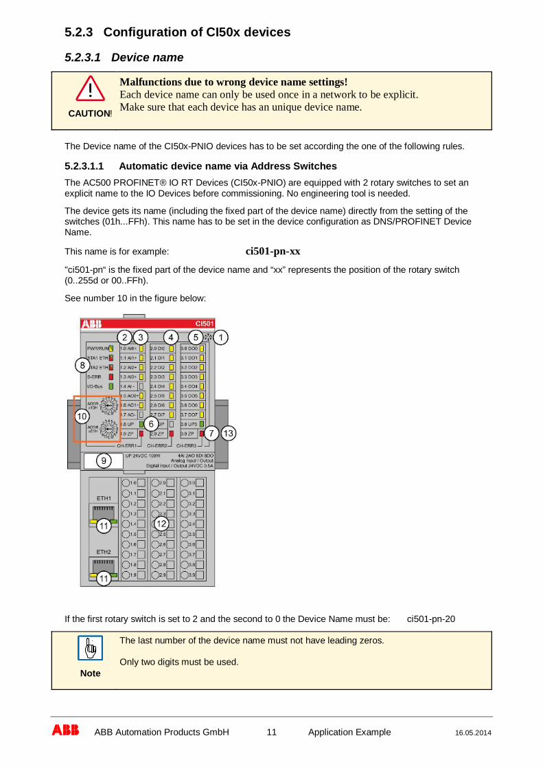
abb ABB Automation Products GmbH 11 Application Example 16.05.2014
5.2.3 Configuration of CI50x devices
5.2.3.1 Device name
CAUTION!
Malfunctions due to wrong device name settings!Each device name can only be used once in a network to be explicit.Make sure that each device has an unique device name.
The Device name of the CI50x-PNIO devices has to be set according the one of the following rules.
5.2.3.1.1 Automatic device name via Address SwitchesThe AC500 PROFINET® IO RT Devices (CI50x-PNIO) are equipped with 2 rotary switches to set anexplicit name to the IO Devices before commissioning. No engineering tool is needed.
The device gets its name (including the fixed part of the device name) directly from the setting of theswitches (01h...FFh). This name has to be set in the device configuration as DNS/PROFINET DeviceName.
This name is for example: ci501-pn-xx
"ci501-pn“ is the fixed part of the device name and “xx” represents the position of the rotary switch(0..255d or 00..FFh).
See number 10 in the figure below:
If the first rotary switch is set to 2 and the second to 0 the Device Name must be: ci501-pn-20
Note
The last number of the device name must not have leading zeros.
Only two digits must be used.
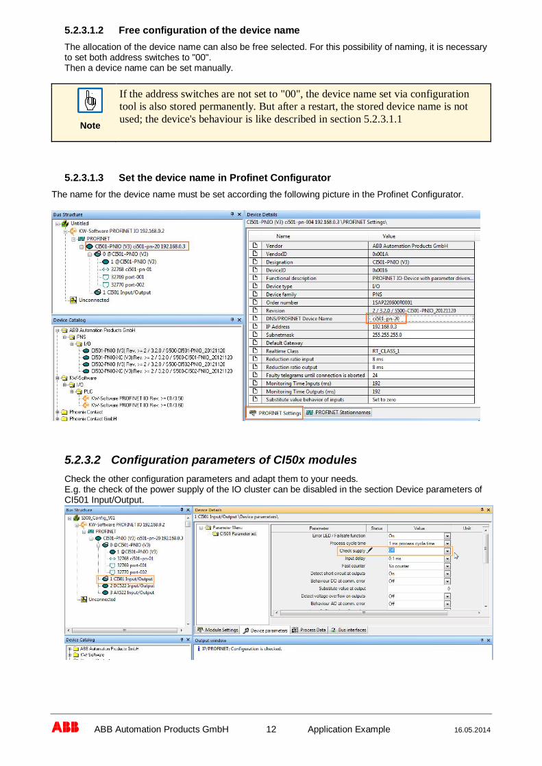
abb ABB Automation Products GmbH 12 Application Example 16.05.2014
5.2.3.1.2 Free configuration of the device nameThe allocation of the device name can also be free selected. For this possibility of naming, it is necessaryto set both address switches to "00".Then a device name can be set manually.
Note
If the address switches are not set to "00", the device name set via configurationtool is also stored permanently. But after a restart, the stored device name is notused; the device's behaviour is like described in section 5.2.3.1.1
5.2.3.1.3 Set the device name in Profinet ConfiguratorThe name for the device name must be set according the following picture in the Profinet Configurator.
5.2.3.2 Configuration parameters of CI50x modulesCheck the other configuration parameters and adapt them to your needs.E.g. the check of the power supply of the IO cluster can be disabled in the section Device parameters ofCI501 Input/Output.

abb ABB Automation Products GmbH 13 Application Example 16.05.2014
5.2.4 Configuration of IO channels and parametersSelect the “CI50x Input/Output” module in the Bus Structure section and select the “Device Parameter”tab in the Device Details section to edit the IO parameters of the module.
E.g. the configuration of the analogue channels
5.2.5 Address mapping of the process dataTo later find the process data in the (group) signals of the IRC5 configuration, the IO addresses of theinputs and outputs should be “stored” to look-up later on.
Open the Process Data tab to see how (many of) the input and output bytes and bits are mapped withinthe module.
e.g. for CI501-PNIO inputs
and outputs:
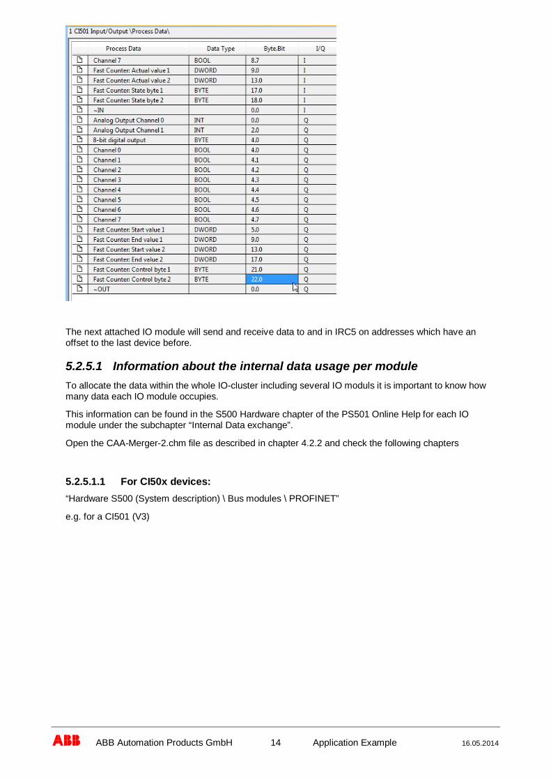
abb ABB Automation Products GmbH 14 Application Example 16.05.2014
The next attached IO module will send and receive data to and in IRC5 on addresses which have anoffset to the last device before.
5.2.5.1 Information about the internal data usage per moduleTo allocate the data within the whole IO-cluster including several IO moduls it is important to know howmany data each IO module occupies.
This information can be found in the S500 Hardware chapter of the PS501 Online Help for each IOmodule under the subchapter “Internal Data exchange”.
Open the CAA-Merger-2.chm file as described in chapter 4.2.2 and check the following chapters
5.2.5.1.1 For CI50x devices:“Hardware S500 (System description) \ Bus modules \ PROFINET”
e.g. for a CI501 (V3)

abb ABB Automation Products GmbH 15 Application Example 16.05.2014
5.2.5.1.2 For IO modules:“S500 \ Hardware S500 (System description) \ Digital Input/Output Modules”or“S500 \ Hardware S500 (System description) \ Analog Input/Output Modules”or“S500 \ Hardware S500 (System description) \ Digital/Analog Input/Output Modules”
e.g. for a DC532

abb ABB Automation Products GmbH 16 Application Example 16.05.2014
5.2.6 Adding more IO ModulesTo add more IO-Modules click on the last IO module in the Bus Structur section.
Double click on the new IO-Module to be added in the Module Catalog section.
NOTICE
Do not select the IO-Modules “With Fast Counter” as the Fast Counter mostly isonly working with AC500 as the Profinet master.
Please check in the S500 documentation (Online Help) if the Fast Counter isavailable only for AC500 Profinet master.This can be found in the Hardware documentation of the according IO Module inthe section “Internal Data Exchange”See chapter 5.2.5.1.2
E.g: DAO501, DI524, DC522, DC523, DC532, DX522
5.2.7 Creation of Profinet Bus configuration file1. Save the project
2. Click on the Profinet master node in the Bus Structur section
3. Check the configuration: Edit \ Check
4. Parametrize: Edit \ Parametrize

abb ABB Automation Products GmbH 17 Application Example 16.05.2014
The IPPNIO.xml configuration file is generated and saved in the project folder.

abb ABB Automation Products GmbH 18 Application Example 16.05.2014
6 Bus and IO Configuration in IRC5
6.1 Bus Configuration setup
6.1.1 Copy the IPPNIO.xml file to the IRC5 controllerUse FTP or USB Stick to copy the IPPNIO.xml file into the HOME directory of the robot system to beused.
6.1.2 Adapt the Bus configuration in the IRC5While being connected to the robot which is to be used as master, navigate to the Bus configuration pagein Robot Studio according the figure below for the selected robot and its bus to adapt.
Request write permission from the connected controller by clicking the “Request Write Access” button inmenu. If the robto is in manual mode, answer the request for mastership at the FlexPendant.
Double click the Profinet_SW bus:

abb ABB Automation Products GmbH 19 Application Example 16.05.2014
1 Enter the name of the bus configuration file “IPPNIO.xml”
2 Enter the IP-Address and subnet mask for the PROFINET master
3 Enter the name of the PROFINET master (must be the same as used in the busconfiguration)
4 If you want an automatic definition of the untis defined in the bus configuration you can usethe Auto Configuration parameter to select the way how the unit shall be defined.
Restart the IRC5 controller twice.The first restart will detect and define the found units from the IPPNIO.xml bus configuration file.With the second restart the new found units will be activated in the IRC5 system.
If you need to adapt signal naming or other settings, this has to be done after the first restart as described inthe following chapters.
6.2 IO-Signal Configuration setupThe following subchapters apply as well to input as well as to output signals.The examples are made for inputs signals only.
6.2.1 Renaming signalsTo verify the signals in the IRC5 program it is helpful to rename the signal according their meaning and oruse.
Navigate to the signal list in the configuration of the IRC5 according the following screenshot:

abb ABB Automation Products GmbH 20 Application Example 16.05.2014
Find the signal you want to adapte and double click it´s entry.
Here you can edit the name of the signal.
6.2.2 Understand the automaticlly generated signal names.If the auto configuration for the units on the bus is used, the IRC5 signal names are generated using thefollowing rule:“device name + In/Out indication + index”.The index is starting at zero and automatically increased by steps of one overall slots of the device.If the auto configuration is set to use group signals, the step will be one for each byte.If single signals is selected, the step will be one for each channel (bit).
In the PROFINET Configurator you can find the meaning of the signals and their slot-internal address asdescribed in chapter 5.2.5

abb ABB Automation Products GmbH 21 Application Example 16.05.2014
Example:
The unit consisting of CI501-PNIO + DC522 + AX522
The CI501 itself has the following Inputs:
This corresponds to the IRC5 group signals in the green frame.
e.g ci501_pn_20_IN2 = Analog Input Channel 1.
The last entry + 1 gives the starting address for the next device.
DC522 itself has the following inputs:

abb ABB Automation Products GmbH 22 Application Example 16.05.2014
This results in a numbering of 18+1 = 19 for the first input byte of the DC522 in IRC5 mapping:
This mechanism applies for all following slots.
E.g. the third module (AX522) input numbering will start with byte number 21 (19 + 2).
6.2.3 Meaningfull definitions of the signalsAll the automatically defined groups are 8 bit group.
The analog values from the IO-devices are managed word wise.
E.g.
ci501_pn_20_IN2 = HighByte of Analog Input Channel 1ci501_pn_20_IN3 = LowByte of Analog Input Channel 1.
Therefore it´s sensefull to adapt the definition of the group signals.
Change the group signal ci501_pn_20_IN2 to a 16 bit input group,change the Unit Mapping to channel 16 – 31 andrename it to “Analog_Input_Channel_1”.
The remaining group ci501_pn_20_IN3 can be deleted now.

abb ABB Automation Products GmbH 23 Application Example 16.05.2014
In the following screenshot you will see the needed changes for the signal ci501_pn_20_IN2.
After the changes have been applied the signal “Analog_Input_Channel_1” will be a input group with 16bits, reflecting the second analog input value of AX522.
6.2.4 Warmstart of the IRC5 controllerTo activate the configured changes the IRC5 controller has to be restarted.
At least once after changing parameters manually.
Twice if automatic bus scan is used. Because the first restart will scan the bus. The second warmstart willactivate the found units.

abb ABB Automation Products GmbH 24 Application Example 16.05.2014
7 Compatibility Hints
The functionality described in this application note was originally tested with the following components andsoftware versions:
Component Hardware Firmware Remark
IRC5 Controller RW 5.15.04, RW 5.60.00
CI501-PNIO Index: C1
CI502-PNIO Index: C2
DC532 Index B4
DC522 Index:B0
AX522 Index: B8
KW-SoftPROFINET Configurator 1.10 Express (File version 1.10.22)
Xml-files for CI50x
S500-CI501-PNIO_20121120_ci501-pn-00_DIM 1.xmlS500-CI501-PNIO_20121120_ci501-pn-00_DIM 2.xmlS500-CI502-PNIO_20121120_ci502-pn-00_DIM 1.xmlS500-CI502-PNIO_20121120_ci502-pn-00_DIM 2.xml

abb ABB Automation Products GmbH 25 Application Example 16.05.2014
8 Related documents
Titel Doc ID Revision
Technical Reference manualSystem parameters IRC5 Document ID: 3HAC17076-1 Revision: R (RW 5.15)
Revision: S (RW 5.60)
Application manualPROFINET Master and Slave SWIRC5
Document ID: 3HAC039906-001 Revision: D (RW 5.15)
Application manualPROFINET IRC5
Document ID: 3HAC047133-001 Revision: - (RW 5.60)
AC500 / S500 Online HelpCAA-Merger-2.chm Document ID 3ADR025078M0203 V2.3.0,
Issue Date 2013-04-30

abb ABB Automation Products GmbH 26 Application Example 16.05.2014

abb
ABB Automation Products GmbHWallstadter Str. 59D-68526 LadenburgTel. : +49 62 21 / 701-1444Fax : +49 62 21 / 701-1382E-Mail : [email protected]
www.abb.com/plc
Man
ualN
o.3A
DR
025
200
M02
01
Doc. kind: No. o. p.:
Application Note 28Title: Lang.:
AC500 communication with a MySQL server EnglishDoc. No
3ADR025200M0201
HISTORYHistoryIndex
Page (P)Chapter (C)
Description DateDept./Initials
A First version March 2014DEAPR/ACM2