Chrysler Lockup, Part 3: CChrysler Lockup, Part 3hrysler ... · CChrysler Lockup, Part 3hrysler...
14
42 GEARS August 2007 I I n the November/December 2006 GEARS, we discussed part two of this three-part series, Mechanical. You learned how the components inside the torque converter worked to seal the converter clutch apply. This included things such as the clutch lining, rubber seal rings and Teflon wipers, as well as one metal clad seal for the input shaft. We also discussed how converter clutch release oil exhausts through the bushing in the converter cover, through channels on the outer diameter of the bushing. This bushing not only keeps the moving components in the convert- er centered, it also allows the release oil to exhaust while maintaining a seal for line pressure inside the torque con- verter. Because of the interruption between the three parts of this series, we reprint- ed part one along with part two: • Part one was Electrical • Part two was Mechanical In this issue of Doctor, Doctor, we’re going to finalize this three-part by Randall Schroeder Chrysler Lockup, Part 3: Dodge RE Torque Dodge RE Torque Converter Electrical, Converter Electrical, Mechanical and Mechanical and Hydraulic Hydraulic Figure 1A: 3rd Gear – TCC Released
Transcript of Chrysler Lockup, Part 3: CChrysler Lockup, Part 3hrysler ... · CChrysler Lockup, Part 3hrysler...

42 GEARS August 2007
Chrysler Lockup, Part 3Chrysler Lockup, Part 3
IIn the November/December 2006 GEARS, we discussed part two of this three-part series, Mechanical.
You learned how the components inside the torque converter worked to seal the converter clutch apply. This included things such as the clutch lining, rubber seal rings and Teflon wipers, as well as one metal clad seal for the input shaft.
We also discussed how converter clutch release oil exhausts through the bushing in the converter cover, through channels on the outer diameter of the bushing. This bushing not only keeps the moving components in the convert-er centered, it also allows the release oil to exhaust while maintaining a seal for line pressure inside the torque con-
verter.Because of the interruption between
the three parts of this series, we reprint-ed part one along with part two: • Part one was Electrical• Part two was Mechanical
In this issue of Doctor, Doctor, we’re going to finalize this three-part
by Randall Schroeder
Chrysler Lockup, Part 3:Dodge RE Torque Dodge RE Torque Converter Electrical, Converter Electrical, Mechanical and Mechanical and HydraulicHydraulic
Figure 1A: 3rd Gear – TCC Released
42Randall807.indd 4242Randall807.indd 42 7/11/07 4:12:32 PM7/11/07 4:12:32 PM
transtar707.indd 40transtar707.indd 40 6/5/07 5:24:16 PM6/5/07 5:24:16 PM

transtar707.indd 41transtar707.indd 41 6/5/07 5:24:26 PM6/5/07 5:24:26 PM
GEARS August 2007 43
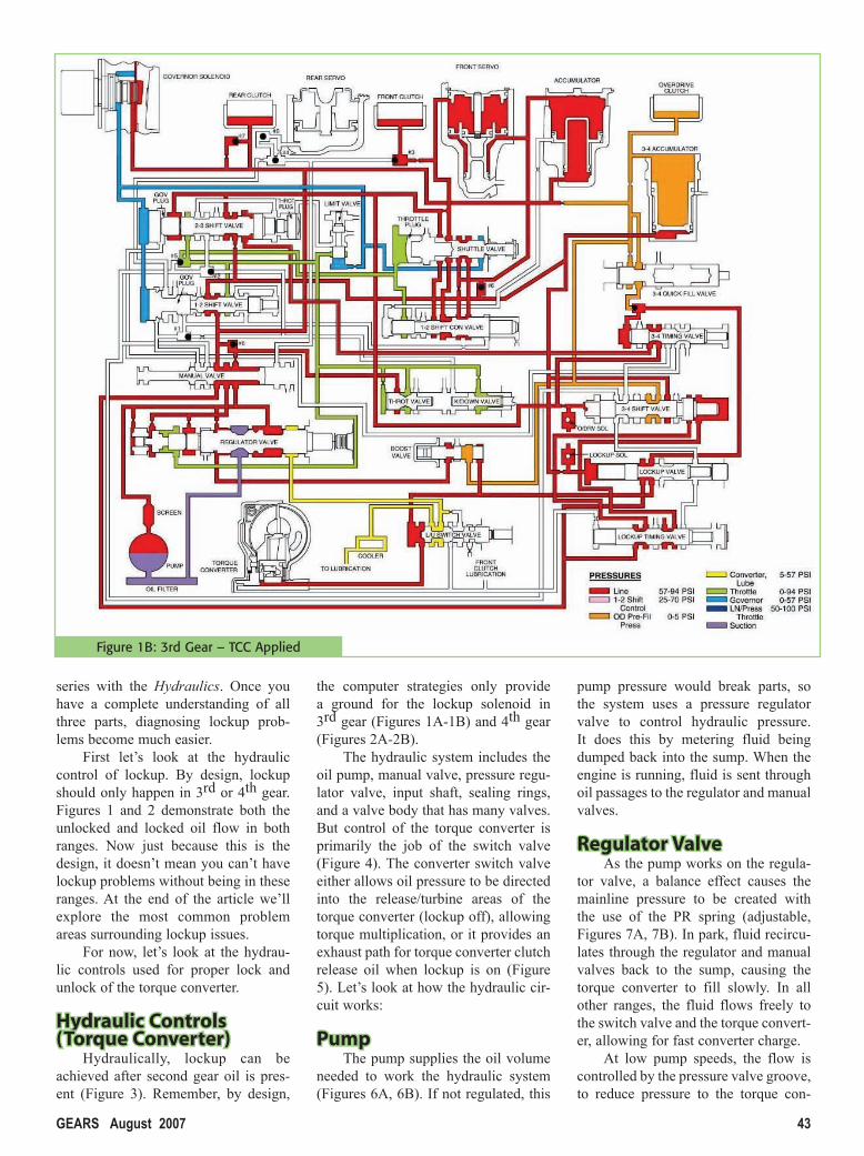
series with the Hydraulics. Once you have a complete understanding of all three parts, diagnosing lockup prob-lems become much easier.
First let’s look at the hydraulic control of lockup. By design, lockup should only happen in 3rd or 4th gear. Figures 1 and 2 demonstrate both the unlocked and locked oil flow in both ranges. Now just because this is the design, it doesn’t mean you can’t have lockup problems without being in these ranges. At the end of the article we’ll explore the most common problem areas surrounding lockup issues.
For now, let’s look at the hydrau-lic controls used for proper lock and unlock of the torque converter.
Hydraulic Controls Hydraulic Controls (Torque Converter)(Torque Converter)
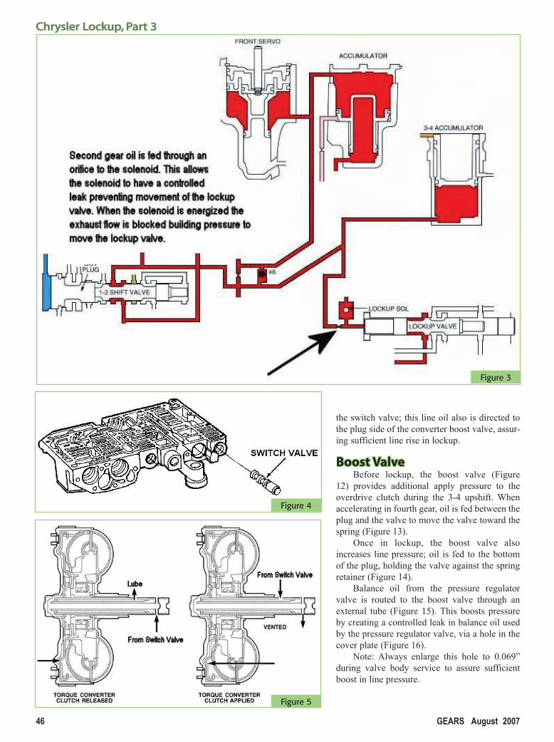
Hydraulically, lockup can be achieved after second gear oil is pres-ent (Figure 3). Remember, by design,
the computer strategies only provide a ground for the lockup solenoid in 3rd gear (Figures 1A-1B) and 4th gear (Figures 2A-2B).
The hydraulic system includes the oil pump, manual valve, pressure regu-lator valve, input shaft, sealing rings, and a valve body that has many valves. But control of the torque converter is primarily the job of the switch valve (Figure 4). The converter switch valve either allows oil pressure to be directed into the release/turbine areas of the torque converter (lockup off), allowing torque multiplication, or it provides an exhaust path for torque converter clutch release oil when lockup is on (Figure 5). Let’s look at how the hydraulic cir-cuit works:
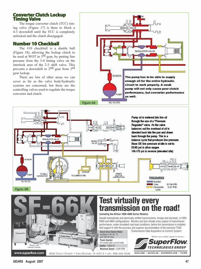
PumpPumpThe pump supplies the oil volume
needed to work the hydraulic system (Figures 6A, 6B). If not regulated, this
pump pressure would break parts, so the system uses a pressure regulator valve to control hydraulic pressure. It does this by metering fluid being dumped back into the sump. When the engine is running, fluid is sent through oil passages to the regulator and manual valves.
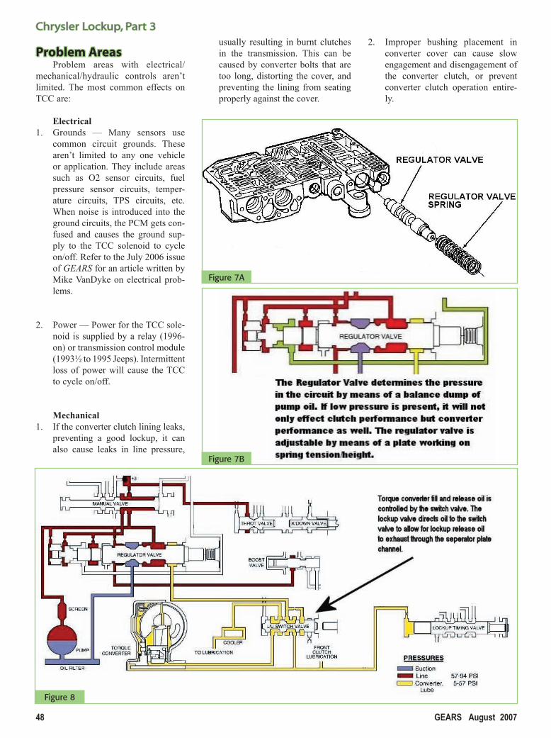
Regulator ValveRegulator ValveAs the pump works on the regula-
tor valve, a balance effect causes the mainline pressure to be created with the use of the PR spring (adjustable, Figures 7A, 7B). In park, fluid recircu-lates through the regulator and manual valves back to the sump, causing the torque converter to fill slowly. In all other ranges, the fluid flows freely to the switch valve and the torque convert-er, allowing for fast converter charge.
At low pump speeds, the flow is controlled by the pressure valve groove, to reduce pressure to the torque con-
Figure 1B: 3rd Gear – TCC Applied
42Randall807.indd 4342Randall807.indd 43 7/11/07 4:12:49 PM7/11/07 4:12:49 PM

44 GEARS August 2007
Chrysler Lockup, Part 3Chrysler Lockup, Part 3
verter. After the torque converter and switch valve fills with fluid, the switch valve becomes the controlling metering device for torque converter pressure. When this occurs, the pressure regula-tor begins to control pressure for the other transmission circuits.
We can spend a whole article just on the regulator valve, but we’ll stop here. Pressure is regulated between 57 and 94 TV PSI (stock condition), except in reverse, where pressure will increase to 145 to 280 TV PSI. Let’s look at the rest of the TCC controlling valves:
Switch ValveSwitch ValveThe switch valve (Figure 8) is the
main metering device for controlling the torque converter. The switch valve directs oil:• from the pressure regulator
valve…• through the center of the transmis-
sion input shaft…• into the converter clutch disc area…• around the clutch lining…• to the turbine/impeller area (torque
multiplication)…
…and back out between the input shaft and the reaction shaft, leading back to the switch valve.
From here, the oil is directed to the transmission cooler, and lubrica-tion pressure returns from the cooler to lubricate different areas of the transmis-sion.
The TCC control valve controls switch valve movement. When the switch valve moves against the spring, converter release oil exhausts to the sump as the converter clutch seals and applies lockup.
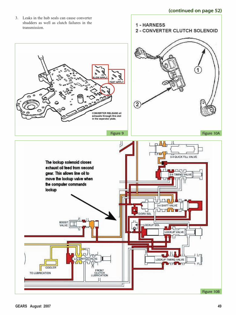
The width of the exhaust slot in the valve body separator plate controls the flow rate for lockup feel: wide slot
= firmer apply, narrow slot = softer apply (Figure 9). Basically, this slot is a control orifice for the flow rate of the release oil as it exhausts from behind the converter clutch.
Sound simple? Let’s continue as we look at the other control factors of TCC hydraulics.
Lockup SolenoidLockup SolenoidThe lockup solenoid controls 2nd
gear oil, which moves the torque con-verter lockup valve (Figures 10A, 10B). Second gear oil is metered through an orifice; when de-energized, the sole-noid exhausts this oil back into the sump. When energized, the solenoid closes the exhaust passageway (leak) and this 2nd gear oil moves the torque converter lockup valve, which, in turn, redirects oil to move the switch valve.
Figure 2A: 4th Gear – TCC Released
42Randall807.indd 4442Randall807.indd 44 7/11/07 4:13:10 PM7/11/07 4:13:10 PM
GEARS August 2007 45
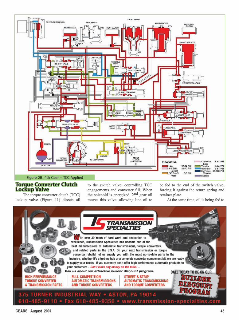
Torque Converter Clutch Torque Converter Clutch Lockup ValveLockup Valve
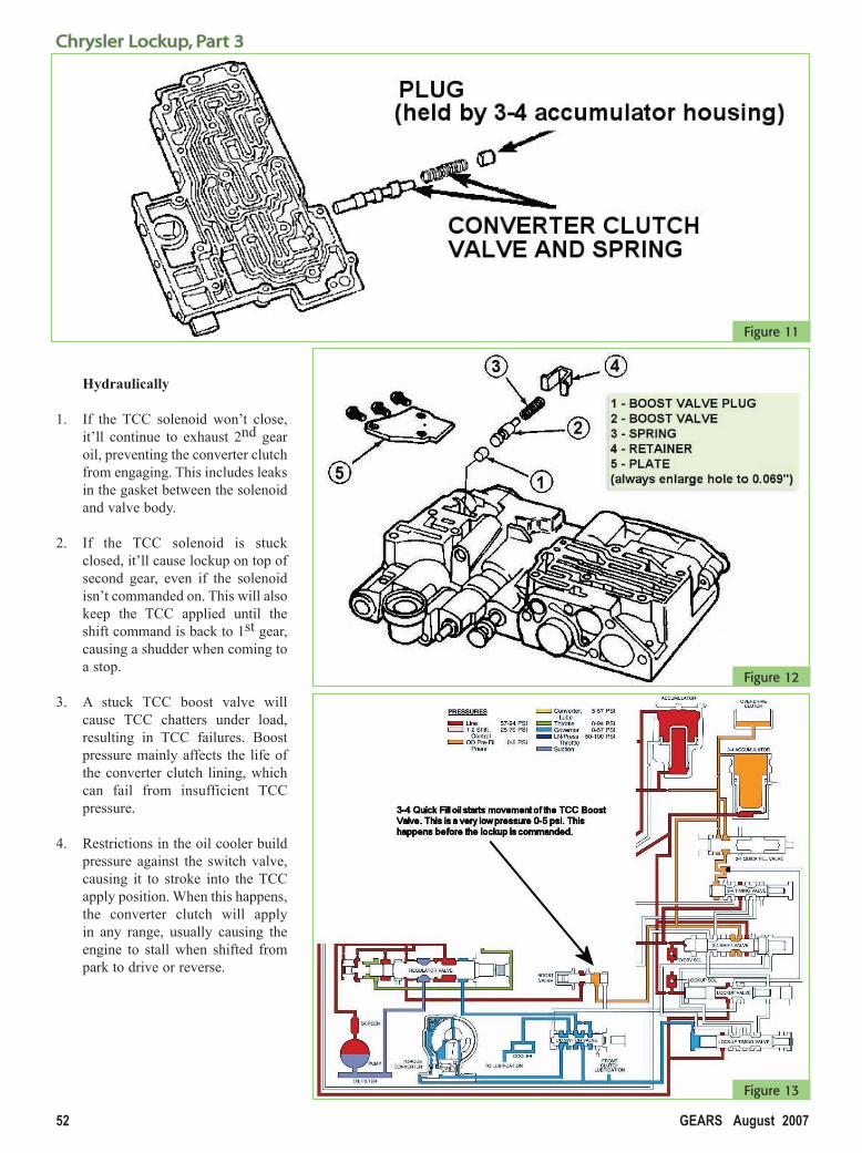
The torque converter clutch (TCC) lockup valve (Figure 11) directs oil
to the switch valve, controlling TCC engagements and converter fill. When the solenoid is energized, 2nd gear oil moves this valve, allowing line oil to
be fed to the end of the switch valve, forcing it against the return spring and retainer plate.
At the same time, oil is being fed to
Figure 2B: 4th Gear – TCC Applied
ith over 30 Years of hard work and dedication toexcellence, Transmission Specialties has become one of thebest manufacturers of automatic transmissions, torque converters,and related parts in the U.S.A. On your next transmission or torqueconverter rebuild, let us supply you with the most up-to-date parts in the
industry, whether it’s a turbine hub or a complete converter component kit, we are readyto supply your needs. If you currently don’t offer high performance automatic products toyour customers - Don’t leave any money on the table. . .
Call us about our attractive builder discount program.
42Randall807.indd 4542Randall807.indd 45 7/11/07 4:13:29 PM7/11/07 4:13:29 PM
46 GEARS August 2007
Chrysler Lockup, Part 3Chrysler Lockup, Part 3
the switch valve; this line oil also is directed to the plug side of the converter boost valve, assur-ing sufficient line rise in lockup.
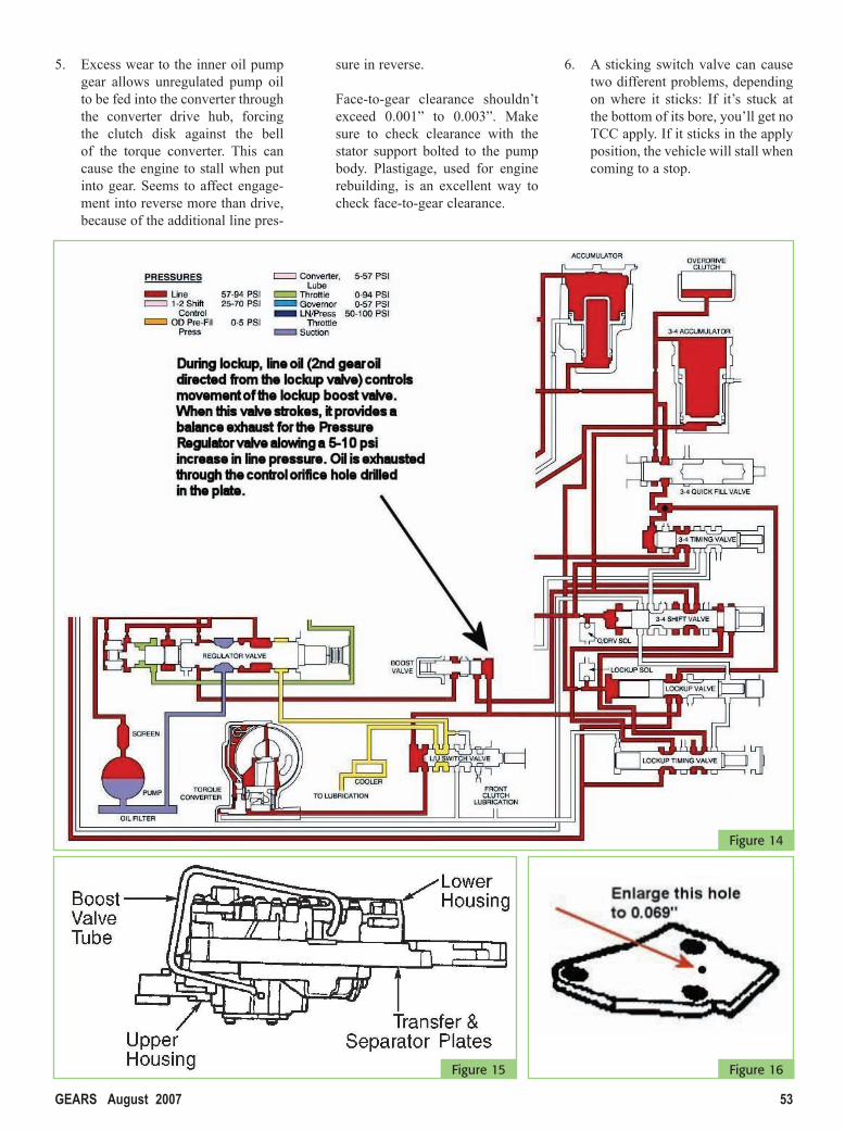
Boost ValveBoost ValveBefore lockup, the boost valve (Figure
12) provides additional apply pressure to the overdrive clutch during the 3-4 upshift. When accelerating in fourth gear, oil is fed between the plug and the valve to move the valve toward the spring (Figure 13).
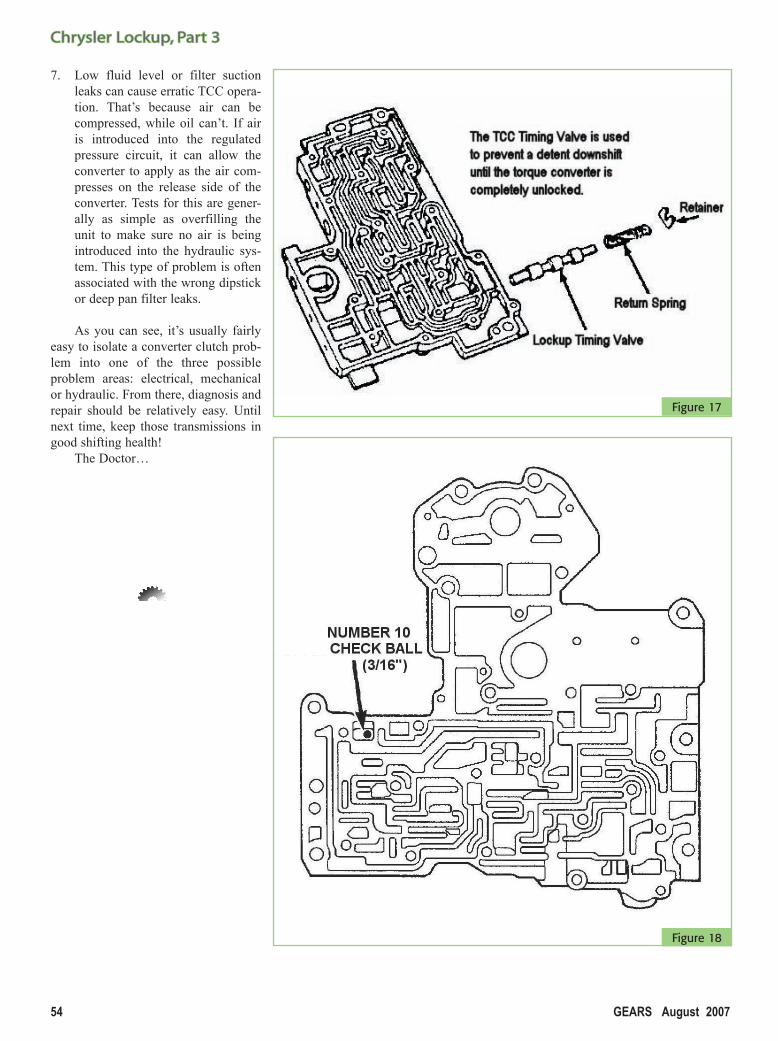
Once in lockup, the boost valve also increases line pressure; oil is fed to the bottom of the plug, holding the valve against the spring retainer (Figure 14).
Balance oil from the pressure regulator valve is routed to the boost valve through an external tube (Figure 15). This boosts pressure by creating a controlled leak in balance oil used by the pressure regulator valve, via a hole in the cover plate (Figure 16).
Note: Always enlarge this hole to 0.069” during valve body service to assure sufficient boost in line pressure.
Figure 3
Figure 5
Figure 4
42Randall807.indd 4642Randall807.indd 46 7/11/07 4:14:00 PM7/11/07 4:14:00 PM
GEARS August 2007 47
Test virtually every transmission on the road!(Including the Allison 1000-4000 Series Models) Handle hydraulically and electrically shifted transmissions, foreign and domestic, in FWD, RWD and AWD confi gurations. Monitor and test virtually every aspect of transmission performance, under simulated road load conditions, before the transmission is installed. And support it with the accuracy and superior documentation of the exclusive TDAC
(Transmission Data Acquisition & Control) System.
www.superfl ow.com
When you really need to know…
4060 Dixon Street • Des Moines, IA 50313 • ph: 888-442-5546
Shown with manual console.
Direct-Drive Electric Motor: Available in 40, 60, 75and 100 HP sizesPower Asorber: Air-cooled eddy current brakeInertia: 125lbs-ft2
Maximum Speed: 5,000 RPM
Converter Clutch Lockup Converter Clutch Lockup Timing ValveTiming Valve
The torque converter clutch (TCC) tim-ing valve (Figure 17) is there to block a 4-3 downshift until the TCC is completely unlocked and the clutch disengaged.
Number 10 CheckballNumber 10 CheckballThe #10 checkball is a shuttle ball
(Figure 18), allowing the lockup clutch to be used at WOT in 3rd gear, by putting line pressure from the 3-4 timing valve on the interlock area of the 2-3 shift valve. This prevents a downshift to 2nd gear from 3rd gear lockup.
There are lots of other areas we can cover as far as the valve body/hydraulic systems are concerned, but these are the controlling valves used to regulate the torque converter and clutch.
Figure 6B
Figure 6A
42Randall807.indd 4742Randall807.indd 47 7/11/07 4:14:19 PM7/11/07 4:14:19 PM
48 GEARS August 2007
Chrysler Lockup, Part 3Chrysler Lockup, Part 3
Problem AreasProblem AreasProblem areas with electrical/
mechanical/hydraulic controls aren’t limited. The most common effects on TCC are:
Electrical1. Grounds — Many sensors use
common circuit grounds. These aren’t limited to any one vehicle or application. They include areas such as O2 sensor circuits, fuel pressure sensor circuits, temper-ature circuits, TPS circuits, etc. When noise is introduced into the ground circuits, the PCM gets con-fused and causes the ground sup-ply to the TCC solenoid to cycle on/off. Refer to the July 2006 issue of GEARS for an article written by Mike VanDyke on electrical prob-lems.
2. Power — Power for the TCC sole-noid is supplied by a relay (1996-on) or transmission control module (1993½ to 1995 Jeeps). Intermittent loss of power will cause the TCC to cycle on/off.
Mechanical1. If the converter clutch lining leaks,
preventing a good lockup, it can also cause leaks in line pressure,
usually resulting in burnt clutches in the transmission. This can be caused by converter bolts that are too long, distorting the cover, and preventing the lining from seating properly against the cover.
2. Improper bushing placement in converter cover can cause slow engagement and disengagement of the converter clutch, or prevent converter clutch operation entire-ly.
Figure 7B
Figure 8
Figure 7A
42Randall807.indd 4842Randall807.indd 48 7/11/07 4:14:43 PM7/11/07 4:14:43 PM
GEARS August 2007 49
3. Leaks in the hub seals can cause converter shudders as well as clutch failures in the transmission.
Figure 10B
Figure 10A
(continued on page 52)(continued on page 52)
Figure 9
42Randall807.indd 4942Randall807.indd 49 7/11/07 4:15:05 PM7/11/07 4:15:05 PM
GEARS August 2007 51
Toll Free (800) 428-8489Fax (805) 604-2001Email [email protected] www.atrabookstore.com
AAll ll GGMM FFaaccttoorryy MMaannuuaallssoonn SSaallee iinn tthhee BBooookkssttoorreeBOOKS NORMALLY SOLD FOR $35 EACH ON SALE
FOR A LIMITED TIME FOR $30 PER BOOK!ALSO SAVE $25 ON THE FACTORY MANUAL CD!
NEW ITEM!!!NEW ITEM!!!
TMG-HYBRID TMG-6T70 TMG-4T80E
TMG-AF23/33-5
TMG-VT20/25E
TMG-6SPEED
Call and order any GM
Technician s̓ Guide for
$30 per book!Sale ends 10/1/07
Hereʼs a sample of just a few of the books that are available!
TMG-CD-NEWTMG-4/5L40E
Regular Price: $100Sale Price: $75
NEW ITEM!!!NEW ITEM!!!
50-Bookstr adv.indd 5150-Bookstr adv.indd 51 7/13/07 8:12:02 AM7/13/07 8:12:02 AM
52 GEARS August 2007
Chrysler Lockup, Part 3Chrysler Lockup, Part 3
Figure 13
Hydraulically
1. If the TCC solenoid won’t close, it’ll continue to exhaust 2nd gear oil, preventing the converter clutch from engaging. This includes leaks in the gasket between the solenoid and valve body.
2. If the TCC solenoid is stuck closed, it’ll cause lockup on top of second gear, even if the solenoid isn’t commanded on. This will also keep the TCC applied until the shift command is back to 1st gear, causing a shudder when coming to a stop.
3. A stuck TCC boost valve will cause TCC chatters under load, resulting in TCC failures. Boost pressure mainly affects the life of the converter clutch lining, which can fail from insufficient TCC pressure.
4. Restrictions in the oil cooler build pressure against the switch valve, causing it to stroke into the TCC apply position. When this happens, the converter clutch will apply in any range, usually causing the engine to stall when shifted from park to drive or reverse.
Figure 12
Figure 11
42Randall807.indd 5242Randall807.indd 52 7/11/07 4:15:30 PM7/11/07 4:15:30 PM
GEARS August 2007 53
5. Excess wear to the inner oil pump gear allows unregulated pump oil to be fed into the converter through the converter drive hub, forcing the clutch disk against the bell of the torque converter. This can cause the engine to stall when put into gear. Seems to affect engage-ment into reverse more than drive, because of the additional line pres-
sure in reverse.
Face-to-gear clearance shouldn’t exceed 0.001” to 0.003”. Make sure to check clearance with the stator support bolted to the pump body. Plastigage, used for engine rebuilding, is an excellent way to check face-to-gear clearance.
6. A sticking switch valve can cause two different problems, depending on where it sticks: If it’s stuck at the bottom of its bore, you’ll get no TCC apply. If it sticks in the apply position, the vehicle will stall when coming to a stop.
Figure 14
Figure 15 Figure 16
42Randall807.indd 5342Randall807.indd 53 7/11/07 4:15:53 PM7/11/07 4:15:53 PM
54 GEARS August 2007
Chrysler Lockup, Part 3Chrysler Lockup, Part 3
7. Low fluid level or filter suction leaks can cause erratic TCC opera-tion. That’s because air can be compressed, while oil can’t. If air is introduced into the regulated pressure circuit, it can allow the converter to apply as the air com-presses on the release side of the converter. Tests for this are gener-ally as simple as overfilling the unit to make sure no air is being introduced into the hydraulic sys-tem. This type of problem is often associated with the wrong dipstick or deep pan filter leaks.
As you can see, it’s usually fairly easy to isolate a converter clutch prob-lem into one of the three possible problem areas: electrical, mechanical or hydraulic. From there, diagnosis and repair should be relatively easy. Until next time, keep those transmissions in good shifting health!
The Doctor…
Figure 17
Figure 18
42Randall807.indd 5442Randall807.indd 54 7/11/07 4:16:14 PM7/11/07 4:16:14 PM


![(52,911)...Allison 4th Generation Electronic Controls wittr closed loop adaptive shifu Shift Sequences [C = Converter mode (lockup clutch disengaged); L = [o*up (lockup clutch engaged)]](https://static.fdocuments.in/doc/165x107/611640d480377e06ac19f53b/52911-allison-4th-generation-electronic-controls-wittr-closed-loop-adaptive.jpg)