CHROMOPHARE Surgical and Examination · PDF fileWall Mounted Intensity Control Box (CFWP)...
23
CHROMOPHARE ® Surgical and Examination Light Pre-Installation Information
Transcript of CHROMOPHARE Surgical and Examination · PDF fileWall Mounted Intensity Control Box (CFWP)...

CHROMOPHARE® Surgical and Examination Light Pre-Installation Information

- 2 -
Table of Contents
�� Introduction...............................................................3
�� Technical Data..........................................................4
�� Hospitals Responsibilities.........................................5
�� Overall Room Schematic..........................................6
�� Wall Mounted Intensity Control Box (CFWP) ...........7
�� SK Box Containing Transformers .............................8
�� Pre-Wiring Instructions .............................................9
�� Superstructure Information .......................................10
�� Weight and Momentum ............................................11
�� Suggested Superstructure........................................13
�� Mounting Rings.........................................................14
�� Wall Box – Installation ..............................................16
�� CFWP Box Electrical Diagram..................................19
�� SK Box Schematic....................................................20
�� SK Box Enclosure.....................................................21

- 3 -
Introduction The Berchtold CHROMOPHARE® C-570, C-571, C-572, C-450, and C-452 represent a modern generation of surgical lights, featuring many technological advances. They are characterized by state of the art electronics, a computer designed polygon reflector, and cardanic suspension of the light head. This includes the following benefits: • Freedom from shadows in the operating field. • High luminous power which generates the brilliance and high color temperature
simulating noontime brightness on a cloudless day. • Easier hygiene due to smooth styling of the light body – the absence of control knobs
on the outer surface, the use of metal and safety glass, and the sealed light head. • Larger range of height adjustment; greater mobility of the light. • Easy replacement of defective halogen or Xenophot bulbs by OR staff. • Cool, single bulb technology, with automatic, instant –on back-up bulb. The construction of mechanics and control functions will be described in detail on the following pages. Diagrams and electrical specifications accompany the descriptions. Installation and mounting instruction manuals are included to aid in the mounting and electrical installation.

- 4 -
Technical Data
Finish RAL 7035 Light field is adjusted by rotating the sterilizable hand grip (1 + 10% (2 Filter system optional
Technical Specifications C571 C572 C450 C452Illuminance at 1 m distance at color temperature 3600 K(1
color temperature 4500 K(1 120,000 lux 100,000 lux
165,000 lux 135,000 lux
70,000 lux 55,000 lux
105,000 lux 85,000 lux
Field diameter continuously adjustable
18 -28 cm 7.1 in. -11.0 in.
17 - 24 cm 6.7 - 9.4 in.
16 - 22 cm 6.5 - 8.7 in.
15 - 21 cm 5.9 - 8.3 in.
Power Requirements 110/120/130 V AC 250 VA 110/120/130 V AC 140 VA
Brightness adjustment Continuous from approx. 50% - 100%Continuous from approx. 50% - 100%
(CFWP only)Power consumption main lamp/reserve lamp 150 W / 24 V, Order No. CZ-908-24 110 W / 22.8 V, Order No.CZ-905-2204Diameter light head 570 mm / 22.4 in. 450 mm / 17.7 in.
Polygon reflector 500 mm / 19.7 in. 410 mm / 16.1 in.
Maximum working range from 70 cm to 200 cm distance from 60 cm to 200 cm distanceAverage service life main lamp/reserve lamp approx 1,000 operating hoursSwivel radius ceiling light 161/176/198.5 cm / 5.3/5.8/6.5 feetSwivel radius wall light 168 cm / 5.5 feetHeight adjustment of the light head 119 cm / 3.9 feetColor rendition index (CRI) 90-94(2
Absorption of infrared radiation 99%Unchanging light field diameter without refocusing constant up to 500 mm height difference

- 5 -
Hospital Responsibilities The hospital, or the hospital’s contractor, must complete the following items before Berchtold’s installation technicians arrive:
1. CFWP box (wall control unit) installed either by recessing in the wall, or surface mounting it. SEE PAGE 7
2. SK box (contains transformers; used with low ceilings) installed either in the
ceiling, or in an area accessible to the technicians. SEE PAGE 8
3. All conduit installed and all necessary wires run. Make all connections in CFWP
and SK box. Conduit from SK box needs to have 18 inches of flexible conduit and wire hanging out of ceiling at mounting plate.
4. Superstructure must be complete, and tested to withstand the maximum torque
of the light.
5. Light mounting plate must be installed to the superstructure making sure that the plate is flush with the finished ceiling.
6. All painting must be complete with finished flooring installed.
* SEE PAGES 7-8

- 6 -
- 7 -
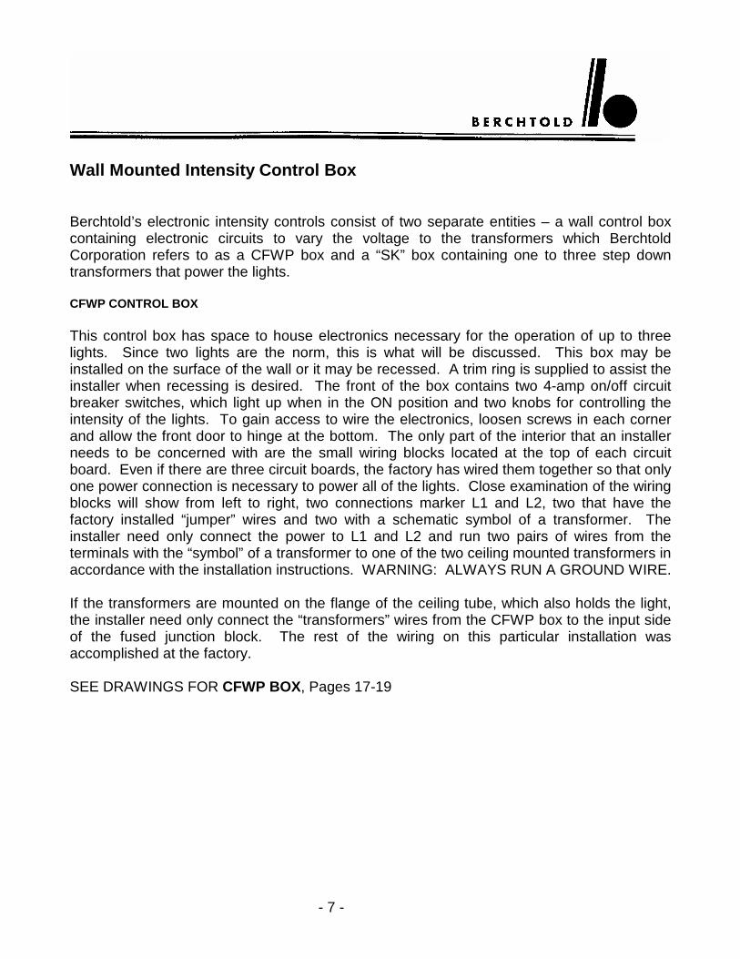
Wall Mounted Intensity Control Box Berchtold’s electronic intensity controls consist of two separate entities – a wall control box containing electronic circuits to vary the voltage to the transformers which Berchtold Corporation refers to as a CFWP box and a “SK” box containing one to three step down transformers that power the lights. CFWP CONTROL BOX This control box has space to house electronics necessary for the operation of up to three lights. Since two lights are the norm, this is what will be discussed. This box may be installed on the surface of the wall or it may be recessed. A trim ring is supplied to assist the installer when recessing is desired. The front of the box contains two 4-amp on/off circuit breaker switches, which light up when in the ON position and two knobs for controlling the intensity of the lights. To gain access to wire the electronics, loosen screws in each corner and allow the front door to hinge at the bottom. The only part of the interior that an installer needs to be concerned with are the small wiring blocks located at the top of each circuit board. Even if there are three circuit boards, the factory has wired them together so that only one power connection is necessary to power all of the lights. Close examination of the wiring blocks will show from left to right, two connections marker L1 and L2, two that have the factory installed “jumper” wires and two with a schematic symbol of a transformer. The installer need only connect the power to L1 and L2 and run two pairs of wires from the terminals with the “symbol” of a transformer to one of the two ceiling mounted transformers in accordance with the installation instructions. WARNING: ALWAYS RUN A GROUND WIRE. If the transformers are mounted on the flange of the ceiling tube, which also holds the light, the installer need only connect the “transformers” wires from the CFWP box to the input side of the fused junction block. The rest of the wiring on this particular installation was accomplished at the factory. SEE DRAWINGS FOR CFWP BOX, Pages 17-19

- 8 -
“SK” Box Containing Transformers If the transformers are NOT installed on the ceiling tube, a SK box containing the transformers must be installed by the installer. This type of installation is always used if the ceiling height does not meet Berchtold Corporation’s specifications. Your sales consultant will tell you in advance which installation your hospital requires. If the lights are being installed in a new construction atmosphere, the SK box may be installed above the ceiling near an access hatch, or in an electrical closet if the closet is reasonably near the surgical suite. If the installation is in a suite where only the light is to be replaced, the hospital engineering department must decide what location would be good for them. Either of the locations mentioned above may be used or in a case where space and access is limited, this box may be surface mounted in the surgery suite itself. The transformers in the SK box are factory wired and are attached to a removable plate. This allows the installer to remove the transformers to make installation of the box easier. Inside the box, the installer will find two electrical connection blocks – one large block which is fused and one smaller block which is not fused. The wires coming from the CFWP box will hook to the large fused connections. This is the input side of the transformers. The output side of the transformers must be connected to the light heads by connecting two pairs of wires from the smaller junction block (not fused) and running them to the factory mounted wiring block positioned on the flange of the ceiling tube. The factory has pre-wired the light heads. The basic theory of the intensity control consists of controlling the line voltage input to the step down transformers, which in turn varies the voltage to the bulbs, used in the light heads. It is the installer’s option as to where he/she mounts the CFWP box or the SK box if used. The only requirement that the manufacturer has is that a minimum of 14 AWG wire be used and if the SK box is mounted an unusual distance from the light, the installer must refer to the wire size tables of the electrical code book to see if 12 AWG wire should be used to carry the necessary 26-28 VAC at 7.2 amps from the SK box to the light junction block. SEE DRAWINGS FOR SK BOX, Pages 20-22

- 9 -
Pre-Wiring Instructions I. PRE-WIRING BERCHTOLD CHROMOPHARE LIGHTS
All Chromophare “C” series lights (regardless of the quantity of light heads) require a single 120-volt supply. This supply should be a 3-wire supply consisting of one HOT, one NEUTRAL, and one GROUND wire. This wire size should be at least 14 AWG, 600 V to meet UL standards. These wires are provided by the hospital, and should be hanging at least 12 inches through the Berchtold mounting ring prior to the Berchtold Service Representative arriving for installation.
II. PRE-WIRING BERCHTOLD CFWP BOXES (See Pages 6 & 16-19)
A. The CFWP box must be mounted in or on the wall in a manner that will provide accessibility to the light controls by the operating room staff.
B. A single 120-volt supply as mentioned above should be provided to the CFWP
box.
C. A 3-wire supply of the same specifications mentioned above should be run from the CFWP box to the mounting ring for the first light head, and an additional two wires run for each additional light head. These wires again should be hanging through the Berchtold mounting ring prior to installation.
III. PRE-WIRING BERCHTOLD CFWP WITH SK BOX (See Pages 6 & 20-22)
A. The CFWP box must be mounted in or on the wall in a manner that will provide accessibility to the light controls by the operating room staff.
B. A single 120-volt supply as mentioned above should be provided to the CFWP
box.
C. A 3-wire supply of the same specifications mentioned above should be run from the CFWP box to the SK Box and from the SK Box to the mounting ring for the first light head, and an additional two wires run for each additional light head. These wires again should be hanging through the Berchtold mounting ring prior to installation.

- 10 -
Superstructure Information
IMPORTANT!IMPORTANT!IMPORTANT!IMPORTANT!
**C**C**C**CHECK WITH YOUR LOCALHECK WITH YOUR LOCALHECK WITH YOUR LOCALHECK WITH YOUR LOCAL CCCCONSTRUCTION ONSTRUCTION ONSTRUCTION ONSTRUCTION EEEENGINEERING NGINEERING NGINEERING NGINEERING
AAAAGENCY TO MEET LOCAL GENCY TO MEET LOCAL GENCY TO MEET LOCAL GENCY TO MEET LOCAL OR STATE CODESOR STATE CODESOR STATE CODESOR STATE CODES. H. H. H. HOSPITAL OSPITAL OSPITAL OSPITAL
((((AND AND AND AND / / / / OROROROR) C) C) C) CONTRACTOR HAS RESPONONTRACTOR HAS RESPONONTRACTOR HAS RESPONONTRACTOR HAS RESPONSIBILITY FOR SIBILITY FOR SIBILITY FOR SIBILITY FOR
SUPERSTRUCTURE STRENSUPERSTRUCTURE STRENSUPERSTRUCTURE STRENSUPERSTRUCTURE STRENGTH AND STABILITYGTH AND STABILITYGTH AND STABILITYGTH AND STABILITY. **. **. **. **

- 11 -
Weight and Momentum
Model Number Total Weight for Design (lbs) Moment (ft. lbs)
C572/224 273 1208 C572/C572/224 341 1475 C572/C452/224 332 1418 C571/224 273 1208 C571/C571/224 341 1475 C571/C450/224 332 1418 C452/224 264 1151 C452/C452/224 322 1363 C450/224 264 1151 C450/C450/224 322 1363 C572 98 439 C572/C572 168 610 C572/C452 159 546 C572/C572/C572 235 877 C572/C572/C452 226 814 C572/C452/C452 217 757 C571 98 439 C571/C571 168 610 C571/C450 159 546 C571/C571/C571 235 877 C571/C571/C450 226 814 C571/C450/C450 217 757

- 12 -
Weight and Momentum (Continued)
Model Number Total Weight for Design (lbs) Moment (ft. lbs)
C452 88 261 C452/C452 149 490 C452/C452/C452 208 702 C450 88 261 C450/C450 149 490 C450/C450/C450 208 702

- 13 -
Suggested Superstructure Pipe Spool Superstructure for Chromophare Installation Check with your local construction engineering agency to meet local or state codes.

- 14 -
Mounting Ring CB-510-3304

- 15 -
Mounting Ring CB-509-4504
- 16 -
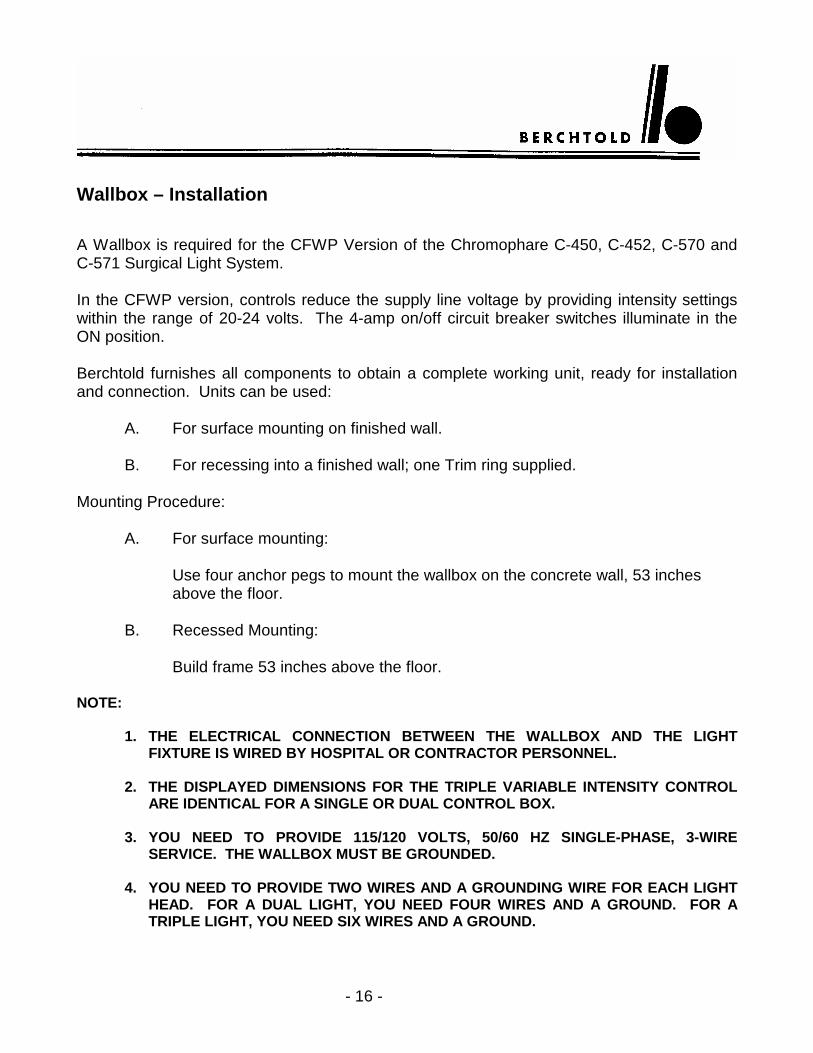
Wallbox – Installation A Wallbox is required for the CFWP Version of the Chromophare C-450, C-452, C-570 and C-571 Surgical Light System. In the CFWP version, controls reduce the supply line voltage by providing intensity settings within the range of 20-24 volts. The 4-amp on/off circuit breaker switches illuminate in the ON position. Berchtold furnishes all components to obtain a complete working unit, ready for installation and connection. Units can be used:
A. For surface mounting on finished wall.
B. For recessing into a finished wall; one Trim ring supplied. Mounting Procedure:
A. For surface mounting:
Use four anchor pegs to mount the wallbox on the concrete wall, 53 inches above the floor.
B. Recessed Mounting:
Build frame 53 inches above the floor. NOTE:
1. THE ELECTRICAL CONNECTION BETWEEN THE WALLBOX AND THE LIGHT FIXTURE IS WIRED BY HOSPITAL OR CONTRACTOR PERSONNEL.
2. THE DISPLAYED DIMENSIONS FOR THE TRIPLE VARIABLE INTENSITY CONTROL
ARE IDENTICAL FOR A SINGLE OR DUAL CONTROL BOX. 3. YOU NEED TO PROVIDE 115/120 VOLTS, 50/60 HZ SINGLE-PHASE, 3-WIRE
SERVICE. THE WALLBOX MUST BE GROUNDED. 4. YOU NEED TO PROVIDE TWO WIRES AND A GROUNDING WIRE FOR EACH LIGHT
HEAD. FOR A DUAL LIGHT, YOU NEED FOUR WIRES AND A GROUND. FOR A TRIPLE LIGHT, YOU NEED SIX WIRES AND A GROUND.

- 17 -
Triple Control Wallbox With Intensity Control
- 18 -
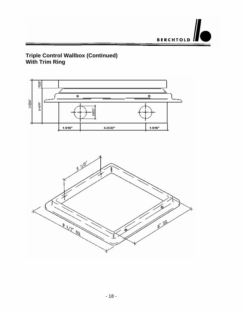
Triple Control Wallbox (Continued) With Trim Ring

- 19 -
Electrical Diagram for Berchtold CHROMOPHARE OR- Light Model C570 & 571 CFWP Single, Double, and Triple Combination
Electrical diagram for Berchtold CHROMOPHARE OR – Light Model C-450, C-452, C570, and C-571 CFWP single, double, and triple combination. Transformers mounted at the ceiling tube of the OR – Light. Light controlled from the wall-box.

- 20 -
SK Box Schematic This type 1 enclosure is 34 lbs. with transformers. It is 12” x 12” x 6” in size with removable panel. This enclosure should be securely mounted above ceiling near light fixture. The location of enclosure must have some means of accessibility.

- 21 -
SK Box Enclosure
Enclosure Size AxBxC
Panel Size DxE
12.00 x12.00x6.00 (305x305x152)
10.25x10.25 (260x260)

- 22 -
NOTES

- 23 -
Safe ����Innovative ����Berchtold
Berchtold Corporation 1950 Hanahan Road P.O. Box 60399 Charleston, SC 29419-0399 800-243-5135 / 803-569-6100 Fax: 803-569-6133