Chopped Prepregs - A Compelling Performance and Cost Alternative … · Chopped Prepregs - A...
11
Chopped Prepregs - A Compelling Performance and Cost Alternative Material Form Tencate Advanced Composites – CCS Composites, LLC 2450 Cordelia Road - Fairfield, CA 94534 info@tcac-usa.com www.tencateadvancedcomposites.com ABSTRACT Chopped prepregs offer another material form for the composite engineers to consider. Some compelling reasons are performance parity, lower total costs, and easier transition from aluminum than continuous fiber composites. Structure - Parts made from chopped unidirectional prepreg will yield similar performance to hand layup continuous fiber composites when knockdown effects are considered. Much of the performance gain for the chopped prepreg material form comes from its low sensitivity to traditional knock down effects. Since the chopped prepreg form has inherent flaws due to stress concentrations at the ends of the short fibers, additional property losses due to holes for attachments, moisture absorption, etc., are minimal. In addition, this chopped material form can be made into complex geometrical shapes that use geometrical stiffening to give it a competitive advantage. Cost – Parts made from chopped unidirectional prepreg can have an advantage over continuous fiber prepreg layups when it comes to labor content. For simple geometries it is much faster to create a random chopped fiber mat than it is to orient and vacuum bag a continuous fiber prepreg layup. In many applications the chopped prepreg form is made into a 3D part that would have required a bonded assembly operation with traditional continuous fiber composites. In order to obtain optimum chopped prepreg structural performance a preform is typically required for complex 3D shapes. The cost trade is two labor intensive continuous prepreg operations (layup/bagging and bonding), for two less demanding chopped prepreg operations (random mat fabrication and preforming). In addition, post processing requirements, such as edge trimming, drilling, insert installation, etc., can be molded to the final condition with chopped prepreg. Eliminating these operations further reduces the cost content of chopped prepreg molding compound as compared with the cost content of continuous fiber prepreg parts. Re-engineering Aluminum – the chopped prepreg form is much better suited to aluminum replacement with composites because of its 3-D molding capabilities. It is still important to engineer some design tradeoffs to achieve the best cost and performance capabilities with the chopped prepreg, but the changes are typically minor part modifications instead of a total redesign effort. This usually results in lowering the engineering costs associated with converting an aluminum part into a composite part driven by a cost or weight savings effort.
Transcript of Chopped Prepregs - A Compelling Performance and Cost Alternative … · Chopped Prepregs - A...
Chopped Prepregs - A Compelling Performance
and Cost Alternative Material Form
Tencate Advanced Composites – CCS Composites, LLC
2450 Cordelia Road - Fairfield, CA 94534
[email protected] www.tencateadvancedcomposites.com
ABSTRACT
Chopped prepregs offer another material form for the composite engineers to consider. Some
compelling reasons are performance parity, lower total costs, and easier transition from
aluminum than continuous fiber composites.
Structure - Parts made from chopped unidirectional prepreg will yield similar performance to
hand layup continuous fiber composites when knockdown effects are considered. Much of the
performance gain for the chopped prepreg material form comes from its low sensitivity to
traditional knock down effects. Since the chopped prepreg form has inherent flaws due to stress
concentrations at the ends of the short fibers, additional property losses due to holes for
attachments, moisture absorption, etc., are minimal. In addition, this chopped material form can
be made into complex geometrical shapes that use geometrical stiffening to give it a competitive
advantage.
Cost – Parts made from chopped unidirectional prepreg can have an advantage over continuous
fiber prepreg layups when it comes to labor content. For simple geometries it is much faster to
create a random chopped fiber mat than it is to orient and vacuum bag a continuous fiber prepreg
layup. In many applications the chopped prepreg form is made into a 3D part that would have
required a bonded assembly operation with traditional continuous fiber composites. In order to
obtain optimum chopped prepreg structural performance a preform is typically required for
complex 3D shapes. The cost trade is two labor intensive continuous prepreg operations
(layup/bagging and bonding), for two less demanding chopped prepreg operations (random mat
fabrication and preforming). In addition, post processing requirements, such as edge trimming,
drilling, insert installation, etc., can be molded to the final condition with chopped prepreg.
Eliminating these operations further reduces the cost content of chopped prepreg molding
compound as compared with the cost content of continuous fiber prepreg parts.
Re-engineering Aluminum – the chopped prepreg form is much better suited to aluminum
replacement with composites because of its 3-D molding capabilities. It is still important to
engineer some design tradeoffs to achieve the best cost and performance capabilities with the
chopped prepreg, but the changes are typically minor part modifications instead of a total redesign
effort. This usually results in lowering the engineering costs associated with converting an
aluminum part into a composite part driven by a cost or weight savings effort.
1. INTRODUCTION
Chopped Prepreg Molding Compound (CPMC) is a relatively new material form. It is similar to
molding compounds that have been made in the past using chopped resin impregnated tow. For
the design and processing engineers, the advantages that chopped prepregs have are variable chip
lengths and widths, resin selection flexibility, and the materials can be pre-formed into shapes,
prior to molding to facilitate fabrication and improve structural performance.
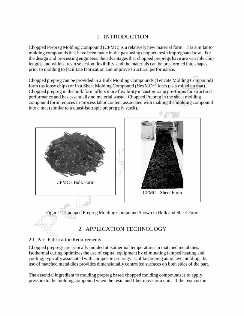
Chopped prepreg can be provided in a Bulk Molding Compounds (Tencate Molding Compound)
form (as loose chips) or in a Sheet Molding Compound (HexMCTM) form (as a rolled up mat).
Chopped prepreg in the bulk form offers more flexibility in customizing pre-forms for structural
performance and has essentially no material waste. Chopped Prepreg in the sheet molding
compound form reduces in-process labor content associated with making the molding compound
into a mat (similar to a quasi-isotropic prepreg ply stack).
CPMC - Bulk Form
CPMC - Sheet Form
Figure 1. Chopped Prepreg Molding Compound Shown in Bulk and Sheet Form
2. APPLICATION TECHNOLOGY
2.1 Part Fabrication Requirements
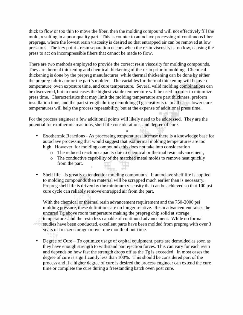
Chopped prepregs are typically molded at isothermal temperatures in matched metal dies.
Isothermal curing optimizes the use of capital equipment by eliminating ramped heating and
cooling, typically associated with composite prepregs. Unlike prepreg autoclave molding, the
use of matched metal dies provides dimensionally controlled surfaces on both sides of the part.
The essential ingredient to molding prepreg based chopped molding compounds is to apply
pressure to the molding compound when the resin and fiber move as a unit. If the resin is too
thick to flow or too thin to move the fiber, then the molding compound will not effectively fill the
mold, resulting in a poor quality part. This is counter to autoclave processing of continuous fiber
prepregs, where the lowest resin viscosity is desired so that entrapped air can be removed at low
pressures. The key point - resin separation occurs when the resin viscosity is too low, causing the
press to act on incompressible fibers that cannot be made to flow.
There are two methods employed to provide the correct resin viscosity for molding compounds.
They are thermal thickening and chemical thickening of the resin prior to molding. Chemical
thickening is done by the prepreg manufacturer, while thermal thickening can be done by either
the prepreg fabricator or the part’s molder. The variables for thermal thickening will be oven
temperature, oven exposure time, and cure temperature. Several valid molding combinations can
be discovered, but in most cases the highest viable temperature will be used in order to minimize
press time. Characteristics that may limit the molding temperature are part thickness, preform
installation time, and the part strength during demolding (Tg sensitivity). In all cases lower cure
temperatures will help the process repeatability, but at the expense of additional press time.
For the process engineer a few additional points will likely need to be addressed. They are the
potential for exothermic reactions, shelf life considerations, and degree of cure.
• Exothermic Reactions - As processing temperatures increase there is a knowledge base for
autoclave processing that would suggest that isothermal molding temperatures are too
high. However, for molding compounds this does not take into consideration
o The reduced reaction capacity due to chemical or thermal resin advancement,
o The conductive capability of the matched metal molds to remove heat quicklyfrom the part.
• Shelf life - Is greatly extended for molding compounds. If autoclave shelf life is applied
to molding compounds then material will be scrapped much earlier than is necessary.
Prepreg shelf life is driven by the minimum viscosity that can be achieved so that 100 psi
cure cycle can reliably remove entrapped air from the part.
With the chemical or thermal resin advancement requirement and the 750-2000 psi
molding pressure, these definitions are no longer relative. Resin advancement raises the
uncured Tg above room temperature making the prepreg chip solid at storage
temperatures and the resin less capable of continued advancement. While no formal
studies have been conducted, excellent parts have been molded from prepreg with over 3
years of freezer storage or over one month of out-time.
• Degree of Cure – To optimize usage of capital equipment, parts are demolded as soon as
they have enough strength to withstand part ejection forces. This can vary for each resin
and depends on how fast the strength drops off as the Tg is exceeded. In most cases the
degree of cure is significantly less than 100%. This should be considered part of the
process and if a higher degree of cure is desired the process engineer can extend the cure
time or complete the cure during a freestanding batch oven post cure.
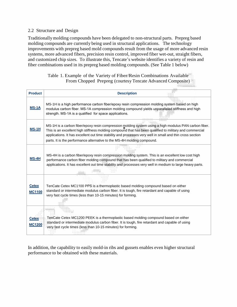
2.2 Structure and Design
Traditionally molding compounds have been delegated to non-structural parts. Prepreg based
molding compounds are currently being used in structural applications. The technology
improvements with prepreg based mold compounds result from the usage of more advanced resin
systems, more advanced fibers, precision resin control, improved fiber wet-out, straight fibers,
and customized chip sizes. To illustrate this, Tencate’s website identifies a variety of resin and
fiber combinations used in its prepreg based molding compounds. (See Table 1 below)
Table 1. Example of the Variety of Fiber/Resin Combinations Available
From Chopped Prepreg (courtesy Tencate Advanced Composite)
Product Description
MS-1H
MS-4H
Cetex
MC1100
MS-4H is a carbon fiber/epoxy resin compression molding system. This is an excellent low cost high
performance carbon fiber molding compound that has been qualified to military and commercial
applications. It has excellent out time stability and processes very well in medium to large heavy parts.
TenCate Cetex MC1200 PEEK is a thermoplastic based molding compound based on either
standard or intermediate modulus carbon fiber. It is tough, fire retardant and capable of using
very fast cycle times (less than 10-15 minutes) for forming.
In addition, the capability to easily mold-in ribs and gussets enables even higher structural
performance to be obtained with these materials.
MS-1H is a carbon fiber/epoxy resin compression molding system using a high modulus PAN carbon fiber.
This is an excellent high stiffness molding compound that has been qualified to military and commercial
applications. It has excellent out time stability and processes very well in small and thin cross section
parts. It is the performance alternative to the MS-4H molding compound.
Cetex
MC1200
TenCate Cetex MC1100 PPS is a thermoplastic based molding compound based on either
standard or intermediate modulus carbon fiber. It is tough, fire retardant and capable of using
very fast cycle times (less than 10-15 minutes) for forming.
MS-1A MS-1H is a high performance carbon fiber/epoxy resin compression molding system based on highmodulus carbon fiber. MS-1A compression molding compound yields unparalleled stiffness and high strength. MS-1A is a qualified for space applications.
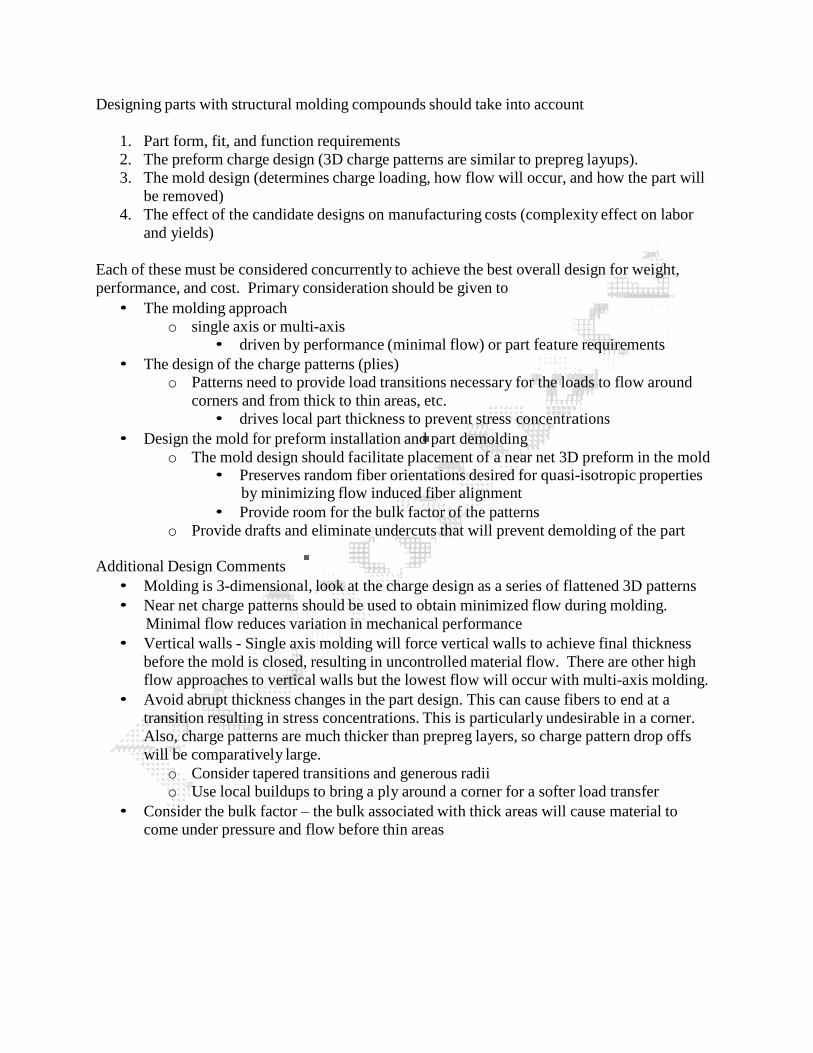
Designing parts with structural molding compounds should take into account
1. Part form, fit, and function requirements
2. The preform charge design (3D charge patterns are similar to prepreg layups).
3. The mold design (determines charge loading, how flow will occur, and how the part will
be removed)
4. The effect of the candidate designs on manufacturing costs (complexity effect on labor
and yields)
Each of these must be considered concurrently to achieve the best overall design for weight,
performance, and cost. Primary consideration should be given to
• The molding approach
o single axis or multi-axis• driven by performance (minimal flow) or part feature requirements
• The design of the charge patterns (plies)o Patterns need to provide load transitions necessary for the loads to flow around
corners and from thick to thin areas, etc.
• drives local part thickness to prevent stress concentrations
• Design the mold for preform installation and part demolding
o The mold design should facilitate placement of a near net 3D preform in the mold• Preserves random fiber orientations desired for quasi-isotropic properties
by minimizing flow induced fiber alignment
• Provide room for the bulk factor of the patterns
o Provide drafts and eliminate undercuts that will prevent demolding of the part
Additional Design Comments
• Molding is 3-dimensional, look at the charge design as a series of flattened 3D patterns
• Near net charge patterns should be used to obtain minimized flow during molding.
Minimal flow reduces variation in mechanical performance
• Vertical walls - Single axis molding will force vertical walls to achieve final thickness
before the mold is closed, resulting in uncontrolled material flow. There are other high
flow approaches to vertical walls but the lowest flow will occur with multi-axis molding.
• Avoid abrupt thickness changes in the part design. This can cause fibers to end at a
transition resulting in stress concentrations. This is particularly undesirable in a corner.
Also, charge patterns are much thicker than prepreg layers, so charge pattern drop offs
will be comparatively large.
o Consider tapered transitions and generous radii
o Use local buildups to bring a ply around a corner for a softer load transfer
• Consider the bulk factor – the bulk associated with thick areas will cause material to
come under pressure and flow before thin areas
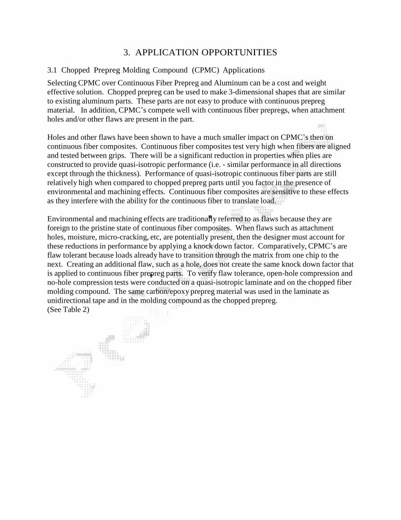
3. APPLICATION OPPORTUNITIES
3.1 Chopped Prepreg Molding Compound (CPMC) Applications
Selecting CPMC over Continuous Fiber Prepreg and Aluminum can be a cost and weight
effective solution. Chopped prepreg can be used to make 3-dimensional shapes that are similar
to existing aluminum parts. These parts are not easy to produce with continuous prepreg
material. In addition, CPMC’s compete well with continuous fiber prepregs, when attachment
holes and/or other flaws are present in the part.
Holes and other flaws have been shown to have a much smaller impact on CPMC’s then on
continuous fiber composites. Continuous fiber composites test very high when fibers are aligned
and tested between grips. There will be a significant reduction in properties when plies are
constructed to provide quasi-isotropic performance (i.e. - similar performance in all directions
except through the thickness). Performance of quasi-isotropic continuous fiber parts are still
relatively high when compared to chopped prepreg parts until you factor in the presence of
environmental and machining effects. Continuous fiber composites are sensitive to these effects
as they interfere with the ability for the continuous fiber to translate load.
Environmental and machining effects are traditionally referred to as flaws because they are
foreign to the pristine state of continuous fiber composites. When flaws such as attachment
holes, moisture, micro-cracking, etc, are potentially present, then the designer must account for
these reductions in performance by applying a knock down factor. Comparatively, CPMC’s are
flaw tolerant because loads already have to transition through the matrix from one chip to the
next. Creating an additional flaw, such as a hole, does not create the same knock down factor that
is applied to continuous fiber prepreg parts. To verify flaw tolerance, open-hole compression and
no-hole compression tests were conducted on a quasi-isotropic laminate and on the chopped fiber
molding compound. The same carbon/epoxy prepreg material was used in the laminate as
unidirectional tape and in the molding compound as the chopped prepreg.
(See Table 2)
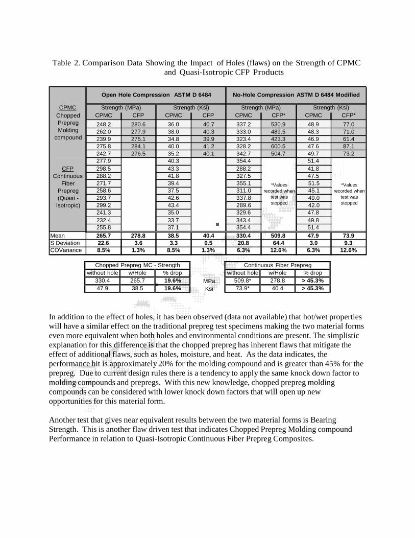
Chopped Prepreg MC - Strength
without hole w/Hole % drop
330.4 265.7 19.6%
47.9 38.5 19.6%
Continuous Fiber Prepreg
without hole w/Hole % drop
509.8* 278.8 > 45.3%
73.9* 40.4 > 45.3%
Table 2. Comparison Data Showing the Impact of Holes (flaws) on the Strength of CPMC
and Quasi-Isotropic CFP Products
Open Hole Compression ASTM D 6484 No-Hole Compression ASTM D 6484 Modified
CPMC Strength (MPa) Strength (Ksi) Strength (MPa) Strength (Ksi)
Chopped
Prepreg
Molding
compound
CPMC CFP CPMC CFP CPMC CFP* CPMC CFP*
248.2 280.6 36.0 40.7 337.2 530.9 48.9 77.0
262.0 277.9 38.0 40.3 333.0 489.5 48.3 71.0
239.9 275.1 34.8 39.9 323.4 423.3 46.9 61.4
275.8 284.1 40.0 41.2 328.2 600.5 47.6 87.1
242.7 276.5 35.2 40.1 342.7 504.7 49.7 73.2
277.9 40.3 354.4 51.4
CFP 298.5 43.3 288.2 41.8
Continuous 288.2 41.8 327.5 47.5
Fiber
Prepreg
(Quasi -
Isotropic)
271.7 39.4 355.1
258.6 37.5 311.0
293.7 42.6 337.8
299.2 43.4 289.6
*Values
recorded when
test was
stopped
51.5
45.1
49.0
42.0
*Values
recorded when
test was
stopped
241.3 35.0 329.6 47.8
232.4 33.7 343.4 49.8
255.8 37.1 354.4 51.4
Mean 265.7 278.8 38.5 40.4 330.4 509.8 47.9 73.9
S Deviation 22.6 3.6 3.3 0.5 20.8 64.4 3.0 9.3
COVariance 8.5% 1.3% 8.5% 1.3% 6.3% 12.6% 6.3% 12.6%
MPa
Ksi
In addition to the effect of holes, it has been observed (data not available) that hot/wet properties
will have a similar effect on the traditional prepreg test specimens making the two material forms
even more equivalent when both holes and environmental conditions are present. The simplistic
explanation for this difference is that the chopped prepreg has inherent flaws that mitigate the
effect of additional flaws, such as holes, moisture, and heat. As the data indicates, the
performance hit is approximately 20% for the molding compound and is greater than 45% for the
prepreg. Due to current design rules there is a tendency to apply the same knock down factor to
molding compounds and prepregs. With this new knowledge, chopped prepreg molding
compounds can be considered with lower knock down factors that will open up new
opportunities for this material form.
Another test that gives near equivalent results between the two material forms is Bearing
Strength. This is another flaw driven test that indicates Chopped Prepreg Molding compound
Performance in relation to Quasi-Isotropic Continuous Fiber Prepreg Composites.
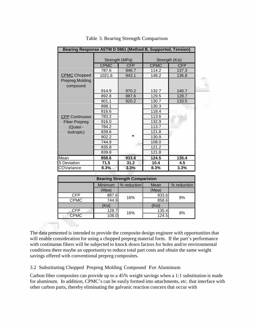
Table 3. Bearing Strength Comparison
Bearing Response ASTM D 5961 (Method B, Supported, Tension)
Strength (MPa) Strength (Ksi)
CPMC CFP CPMC CFP
CPMC Chopped
Prepreg Molding
compound
787.6 946.7 114.2 137.3
1021.6 943.1 148.2 136.8
914.9 970.2 132.7 140.7
892.8 887.6 129.5 128.7
901.1 920.2 130.7 133.5
CFP Continuous
Fiber Prepreg
(Quasi -
Isotropic)
898.1 130.3
816.6 118.4
783.2 113.6
916.0 132.9
784.2 113.7
839.6 121.8
902.2 130.9
744.9 108.0
835.8 121.2
839.8 121.8
Mean 858.6 933.6 124.5 135.4 S Deviation 71.5 31.2 10.4 4.5
COVariance 8.3% 3.3% 8.3% 3.3%
Bearing Strength Comparision
Minimum % reduction Mean % reduction
(Mpa) (Mpa)
CFP 887.6 16%
933.6 8%
CPMC 744.9 858.6
(Ksi) (Ksi)
CFP 128.7 16%
135.4 8%
CPMC 108.0 124.5
The data presented is intended to provide the composite design engineer with opportunities that
will enable consideration for using a chopped prepreg material form. If the part’s performance
with continuous fibers will be subjected to knock down factors for holes and/or environmental
conditions there maybe an opportunity to reduce total part costs and obtain the same weight
savings offered with conventional prepreg composites.
3.2 Substituting Chopped Prepreg Molding Compound For Aluminum
Carbon fiber composites can provide up to a 45% weight savings when a 1:1 substitution is made
for aluminum. In addition, CPMC’s can be easily formed into attachments, etc. that interface with
other carbon parts, thereby eliminating the galvanic reaction concern that occur with
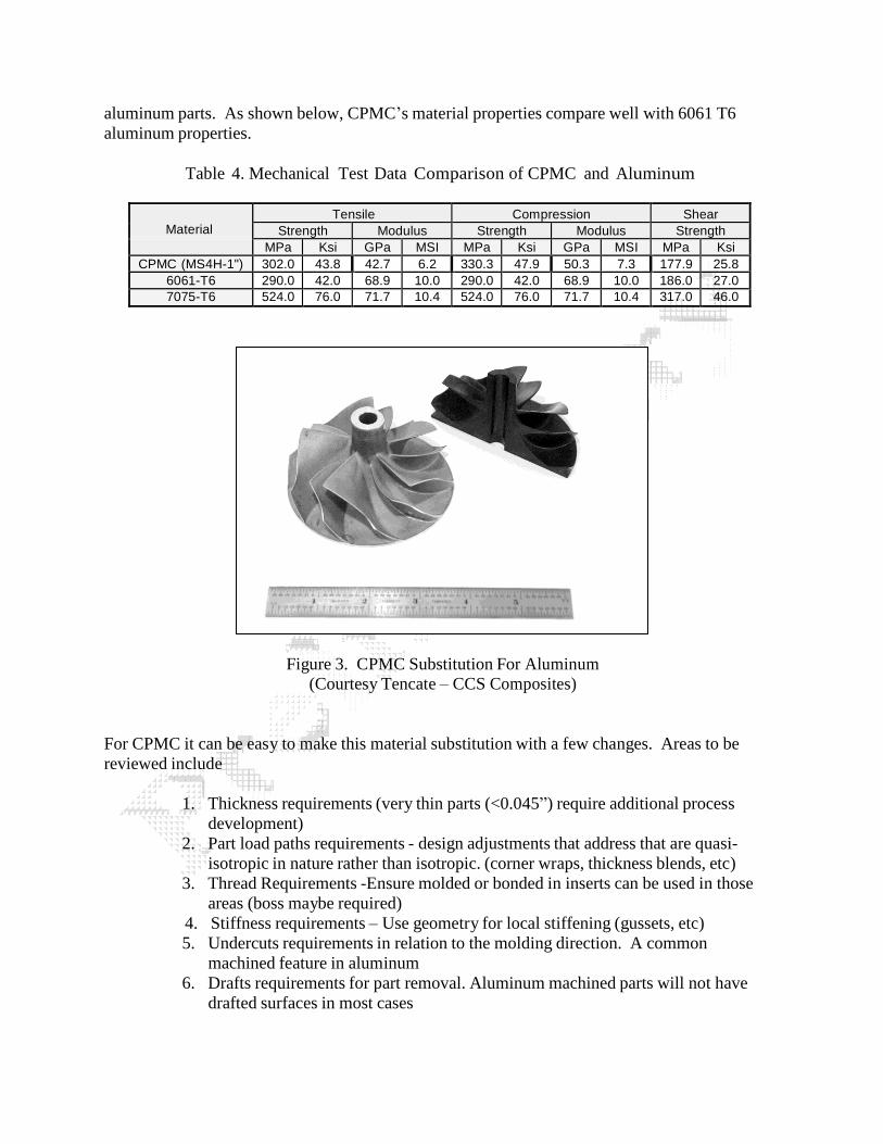
aluminum parts. As shown below, CPMC’s material properties compare well with 6061 T6
aluminum properties.
Table 4. Mechanical Test Data Comparison of CPMC and Aluminum
Material Tensile Compression Shear
Strength Modulus Strength Modulus Strength
MPa Ksi GPa MSI MPa Ksi GPa MSI MPa Ksi
CPMC (MS4H-1") 302.0 43.8 42.7 6.2 330.3 47.9 50.3 7.3 177.9 25.8
6061-T6 290.0 42.0 68.9 10.0 290.0 42.0 68.9 10.0 186.0 27.0
7075-T6 524.0 76.0 71.7 10.4 524.0 76.0 71.7 10.4 317.0 46.0
Figure 3. CPMC Substitution For Aluminum
(Courtesy Tencate – CCS Composites)
For CPMC it can be easy to make this material substitution with a few changes. Areas to be
reviewed include
1. Thickness requirements (very thin parts (<0.045”) require additional process
development)
2. Part load paths requirements - design adjustments that address that are quasi-
isotropic in nature rather than isotropic. (corner wraps, thickness blends, etc)
3. Thread Requirements -Ensure molded or bonded in inserts can be used in those
areas (boss maybe required)
4. Stiffness requirements – Use geometry for local stiffening (gussets, etc)
5. Undercuts requirements in relation to the molding direction. A common
machined feature in aluminum
6. Drafts requirements for part removal. Aluminum machined parts will not have
drafted surfaces in most cases
As a final thought, consider giving up some weight savings to reduce tooling costs, reduce
fabrication costs, and improve process repeatability. In many cases, after making adjustments to
address performance and cost, the weight savings will be in the 25-35% range. Beyond weight
savings and galvanic reaction advantages, using a carbon chopped prepreg molding compounds
in place of aluminum can provide radio translucency and improved fatigue performance.
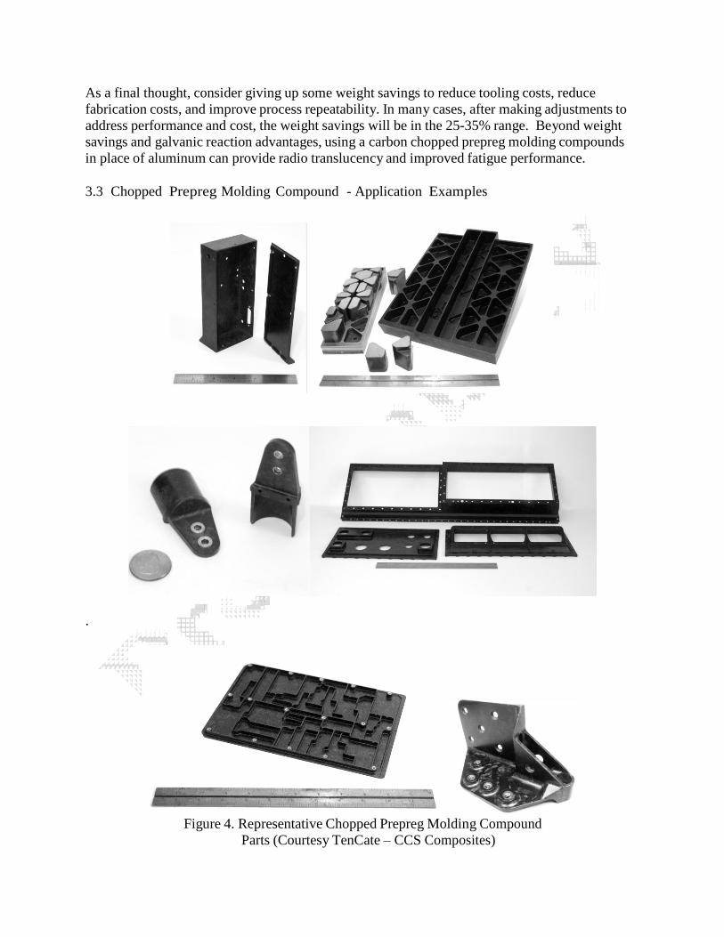
3.3 Chopped Prepreg Molding Compound - Application Examples
.
Figure 4. Representative Chopped Prepreg Molding Compound
Parts (Courtesy TenCate – CCS Composites)
4. CONCLUSION
As a new material form, chopped prepreg molding compounds (CPMC) have compelling
advantages to offer over continuous fiber prepreg and aluminum, in certain applications.
Engineering considerations were discussed for both the design and fabrication of chopped
prepreg based parts. The applications for competition with continuous fiber prepreg part designs
occur when flaw conditions are added, such as attachment holes and environmental conditions.
For aluminum, CPMCs offer a more direct conversion due to their 3D molding capabilities. In
addition, opportunities exist to replace 6061-T6 or similar aluminum parts on a 1:1 strength basis
and achieve a very high weight savings. As composites gain momentum in primary structural
applications there is a real need to replace aluminum interfacing components with materials that
do not create a galvanic reaction with carbon. The 3D geometry and high structural requirements
make Chopped Prepreg Molding Compounds a good candidate for meeting these demands.
Authored by Jack D. Fudge PE
5. REFERENCES
1. Fudge, J., 2001 “HexMCTM
– Composites in 3D”, SAMPE, May 6-10, 2001, (121-13 pages)
2. Fudge, J., 2001 “HexMCTM
- A Prepreg Quality SMC”, American Society for Composites,
Sixteenth Technical Conference, September 9-12, 2001, (156-12 pages)
3. Starbuck, J.M. and G. C. Jacob, and S. Simunovic, 2001 “Energy Absorption in Chopped
Carbon Fiber Compression Molded Composites” American Society for Composites,
Sixteenth Technical Conference, September 9-12, 2001, (131-13 pages)