Chilled Beam Design Guide - seedengr.comseedengr.com/Chilled Beam Design Guide.pdf · Chilled Beam...
68
Chilled Beam Design Guide Trox USA, Inc. 4305 Settingdown Circle Cumming Georgia USA 30028 Telephone 770-569-1433 Facsimile 770-569-1435 www.troxusa.com e-mail [email protected] TB012309
Transcript of Chilled Beam Design Guide - seedengr.comseedengr.com/Chilled Beam Design Guide.pdf · Chilled Beam...

Chilled Beam Design Guide
Trox USA, Inc. 4305 Settingdown Circle Cumming Georgia USA 30028
Telephone 770-569-1433 Facsimile 770-569-1435 www.troxusa.com e-mail [email protected]
TB012309
2
Introduction to Chilled Beams 3 Passive chilled beams 3 Active chilled beams 5 System Application Guidelines 8 Benefits of chilled beams 8 Chilled beam applications 9 Multiservice Chilled Beams 11 System Design Guidelines 14 Comfort considerations 14 Air side design 15 Water side design 19 Control considerations 21 Installation and commissioning 24
Chilled Beam Selection 27 Passive beams selection 27 Passive beam performance data 28 Selection examples 31 Active beam selection 32 Active beam selection examples 35 Performance Notes 38 Active Beam Performance Data 39 Coil pressure loss data 39 DID600 series beams 44 DID620 series beams 52 DID300 series beams 62 Chilled Beam Specifications 68
Contents
Notice to Users of this Guide
This Guide is intended for the sole use of professionals involved in the design and specification of TROX chilled beam systems. Any reproduction of this document in any form is strictly prohibited without the written consent of
TROX USA.
The content herein is a collection of information from TROX and other sources that is assumed to be correct and current at the time of publication. Due to industry and product development, any and all of such content is subject to change. TROX USA will in no way be held responsible for the application of this information to system design
nor will they be responsible for keeping the information up to date.

3
Introduction
Chilled beams have been employed in European HVAC sensible cooling only applications for over twenty years. Within the past few years they have become a popular alternative to VAV systems in North America. The growing interest in chilled beams has been fueled by their energy saving potential, ease of use as well as their minimal space requirements. Chilled beams were originally developed to supersede the outputs achieved by passive radiant cooling ceiling systems. Sensible cooling capacities of “chilled” ceilings are limited by the chilled water supply temperature (must be maintained above dew point to prevent condensation from forming on their surfaces) and the total surface area available that can be „chilled‟. Obviously, this area is limited as other services (lighting, fire protection, air distribution & extract etc.) limit the degree of employment of the active ceiling surface such that their maximum space sensible cooling capacity is very typically less than 25 BTUH per square foot of floor area. As this is not sufficient for maintaining comfort especially in perimeter areas, chilled beams very quickly became the preferred solution in so much as they occupied less space, had fewer connection and most importantly offered sensible cooling outputs 2 to 3 times that of „chilled‟ ceilings.
INTRODUCTION TO CHILLED BEAMS
Chilled beams feature finned chilled water heat exchanger cooling coils, capable of providing up to 1100 BTUH of sensible cooling per foot of length and are designed to take advantage of the significantly higher cooling efficiencies of water. Figure 1 illustrates that a one inch diameter water pipe can transport the same cooling energy as an 18 inch square air duct. The use of chilled beams can thus dramatically reduce air handler and ductwork sizes enabling more efficient use of both horizontal and vertical building space.
There are two basic types of chilled beams (see figure 2). Passive chilled beams are simply finned tube heat exchanger coil within a casing that provides primarily convective cooling to the space. Passive beams do not incorporate fans or any other components (ductwork, nozzles, etc.) to affect air movement. Instead they rely on natural buoyancy to recirculate air from the conditioned space and therefore needs a high free area passage to allow room air to get above the coil and cooled air to be discharge from below the coil. As they have no provisions for supplying primary air to the space, a separate source must provide space ventilation and/or humidity control, very typically combined with, but not limited to, UFAD. The air source commonly contributes to the sensible cooling of the space as well as controlling the space latent gains.
Active chilled beams utilize a ducted (primary) air supply to induce secondary (room) air across their integral heat transfer coil where it is reconditioned prior to its mixing with the primary air stream and subsequent discharge into the space. The primary air supply is typically pretreated to maintain ventilation and humidity control of the space. The heat transfer coil
Figure 1: Cooling Energy Transport Economies of Air and Water
Figure 2: Basic Beam Types
18“ x 18“ Air Duct
1“ diameter Water Pipe
Passive Chilled Beam(Exposed Beam Shown)
Active Chilled Beam

4
Passive Chilled Beams
provides sensible cooling, it is not used to condense or provide latent cooling. Further discussion of the performance, capacities and design considerations for each type of beam is provided in the following sections of this document. PASSIVE CHILLED BEAMS Passive chilled beams are completely decoupled from the space air supply and only intended to remove sensi-ble heat from the space. They operate most efficiently when used in thermally stratified spaces. Figure 3. illustrates the operational principle of a pas-sive beam. Warm air plumes from heat sources rise naturally and create a warm air pool in the upper portion of the space (or ceiling cavity). As this air contacts the coil surface, the heat is removed which causes it to drop back into the space due to its negative buoyancy relative to the air surrounding it. The heat is absorbed lifting the chilled water temperature and is removed from the space via the return water circuit. About 85% of the heat removal is by convective means, therefore the radiant cooling contribution of passive chilled beams is minimal and typically ignored.
Passive chilled beams are capable of removing 200 to 650 BTUH of sensible heat per linear foot of length depending upon their width and the temperature difference between their entering air and chilled water mean temperature. The output of the chilled beam is usually limited to ensure that the velocity of the air dropping out of the beam face and back into the occupied zone does not create drafts. It should also be noted that the air descending from a passive beam „necks‟ rather like slow running water out of a faucet. This slow discharge can be effected by other air currents around it and should passive beams be installed side by side, the two airstreams will join and
combine resulting in a higher velocity in the occupied space. Air discharge across the face of the beam should be avoided as this can reduce the cooling output by inhibiting the flow of warm air into the heat ex-changer coil. Passive Chilled Beam Variations Passive chilled beams may be located above or below the ceiling plane. When used with a suspended ceiling system recessed beams, TROX TCB-RB, are located a few inches above the ceiling and finished to minimize their visibility from below. Figure 4. illustrates such a recessed beam application.
Recessed beams are concealed above the hung ceiling and should also include a separation skirt (TCB-RB-Skirt) which assures that the cooled air does not short circuit back to the warm air stream feeding the beam. Recessed beams (TROX series TCB) may be either uncapped (standard) or capped (more commonly known as shrouded) (see figure 5). Capped or shrouded beams have a sheet metal casing which maintains separation between the beam and the ceiling air cavity which is often used for the space return air passage. This also provides acoustical separation be-tween adjacent spaces.
Passive beams mounted flush with or below the ceiling surface are referred to as exposed beams. Most ex-posed beams (e.g., TROX TCB-EB and PKV series) are furnished within cabinets designed to enhance the ar-chitectural features of the space as well as assure the necessary air passages for the beam.
Figure 3: Passive Beam Operation
Figure 4: Recessed Beam Installation
Separation Skirt
Figure 5: Capped Passive Beam

5
Active Chilled Beams
TROX Passive Chilled Beams TROX USA offers 2 ranges of passive chilled beam as the core engine behind the variants.
TCBU series beams offer a full range of 1 & 2 row recessed and exposed passive beams.
PKVU series beams are 1 row passive beams
with or without exposed cabinets. Figure 6 illustrates an exposed passive beam in whose cabinet other space services (lighting, smoke and occupancy detectors, etc.) have been integrated. Such integrated beams are referred to as integrated or multi-service chilled beams (MSCB). As with recessed beams, it is generally recommended that the cross sectional free area of the passage into an exposed chilled beam be equal to at least one its width. For more information on these beams see pages 27-31.
ACTIVE CHILLED BEAMS In addition to chilled water coil(s), active chilled beams incorporate ducted air connections to receive pretreated supply air from a central air handling unit. This air is injected through a series of nozzles within the beam to entrain room air. Figure 7 illustrates an active beam that induces room air through a high free area section within its face and through the integral heat transfer coil where it is reconditioned in response to a space thermostat demand. The reconditioned air then mixes with the ducted (primary) air and is discharged into the space by means of linear slots located along the outside edges of the beam. Active beams mounted above the occupied zone maintain a sufficient discharge velocity to maintain a fully mixed room air distribution. As such, they employ a dilution ventilation strategy to manage the level of airborne gaseous and particulate contaminants. Certain variants of active beams (see discussion below) may be mounted in low sidewall or floor level applications as
well. In these cases, displacement ventilation and con-ditioning will be used to produce a thermally stratified room environment. Active chilled beams typically operate at a constant air volume flow rate, producing a variable temperature discharge to the space determined by the recirculated air heat extraction. As the water circuit can generally extract 50 to 70% of the space sensible heat genera-tion, the ducted airflow rate can often be reduced ac-cordingly, resulting in reduced air handling requirements as well as significantly smaller supply (and ex-haust/return) ductwork and risers. Active chilled beams can provide sensible cooling rates as high as 1100 BTUH per linear foot, depending on their induction capabilities, coil circuitry, and chilled water supply temperature. Later in this guide, you will see that careful selection of the beam must be made to ensure that high terminal velocities are avoided to main-tain comfort, a beam is not just a method of providing cooling, but also a terminal discharge device that has to be selected to suit the location, space and how the space is being utilized. Active chilled beams can be used for heating as well, provided the façade heat losses are moderate. Active Chilled Beam Variations Active chilled beams come in a number of lengths and widths allowing their use in exposed mounting or integration into suspended ceiling systems, (their weight requires they be independently supported). They can be furnished with a variety of nozzle types that affect the induction rate of room air. Their discharge pattern can be supplied as either one or two way while some beams allow modification of their discharge characteristics once installed. Finally, some variants are available with condensate trays designed to collect a limited amount of unexpected condensation.
Figure 6: Exposed Beam Installation
Primary air
supply
Suspended
ceiling
Figure 7: Active Chilled Beam Operation
6
Active Chilled Beams
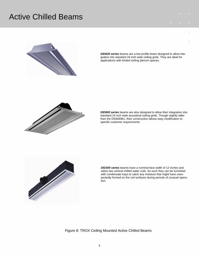
Figure 8: TROX Ceiling Mounted Active Chilled Beams
DID620 series beams are a low profile beam designed to allow inte-gration into standard 24 inch wide ceiling grids. They are ideal for applications with limited ceiling plenum spaces.
DID600 series beams are also designed to allow their integration into standard 24 inch wide acoustical ceiling grids. Though slightly taller than the DID600BU, their construction allows easy modification to specific customer requirements.
DID300 series beams have a nominal face width of 12 inches and utilize two vertical chilled water coils. As such they can be furnished with condensate trays to catch any moisture that might have unex-pectedly formed on the coil surfaces during periods of unusual opera-tion.
7
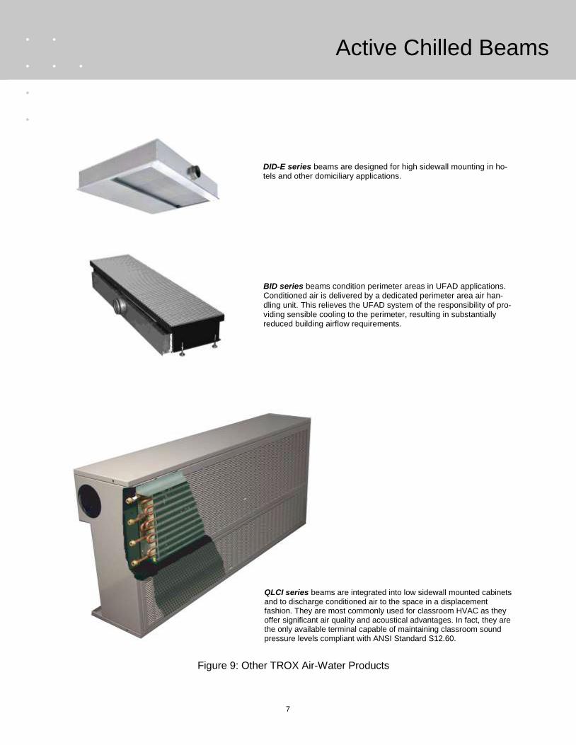
Figure 9: Other TROX Air-Water Products
Active Chilled Beams
BID series beams condition perimeter areas in UFAD applications. Conditioned air is delivered by a dedicated perimeter area air han-dling unit. This relieves the UFAD system of the responsibility of pro-viding sensible cooling to the perimeter, resulting in substantially reduced building airflow requirements.
DID-E series beams are designed for high sidewall mounting in ho-tels and other domiciliary applications.
QLCI series beams are integrated into low sidewall mounted cabinets and to discharge conditioned air to the space in a displacement fashion. They are most commonly used for classroom HVAC as they offer significant air quality and acoustical advantages. In fact, they are the only available terminal capable of maintaining classroom sound pressure levels compliant with ANSI Standard S12.60.

8
Benefits of Chilled Beams
CHILLED BEAM SYSTEM APPLICATION GUIDELINES Chilled beams (both passive and active) posses certain inherent advantages over all-air systems. These benefits can be divided into the three categories as follows: First cost benefits of chilled beam systems Chilled beams afford the designer an opportunity to replace large supply and return air ductwork with small chilled water pipes. This results in significant savings in terms of plenum space and increases usable floor space.
• Chilled beams can be mounted in ceiling spaces as small as 8 to 10 (vertical) inches while all-air systems typically require to 2 to 2.5 times that. This vertical space savings can be used to either increase the space ceiling height or reduce the slab spacing and thus the overall building height requirements.
• The low plenum requirements of chilled beam
systems make them ideal choices for retrofit of buildings that have previously used sidewall mounted equipment such as induction units, fan coils and other unitary terminals.
• Chilled beams contribute to horizontal space
savings as their significantly lower supply airflow rates result in smaller supply and re-turn/exhaust air risers. The capacity of the air handling units providing conditioned air to the chilled beam system is also reduced, resulting in considerably smaller equipment room foot prints.
• LEEDTM also requires that certified buildings
be purged for a period of time before occupancy in order to remove airborne contaminants related to the construction proc-ess. The significantly reduced airflow require-ment of chilled beam systems reduces the fan energy required to accomplish this task.
Operational cost benefits of chilled beam systems The energy costs of operating chilled beam systems are considerably lower than that of all-air systems. This is largely due to the following:
Reduced supply air flow rates result in lower fan energy consumption.
• Operational efficiencies of pumps are
intrinsically higher than fans, leading to much lower cooling and heating energy transport costs.
• Higher chilled water temperatures used by chilled beams may allow chiller efficiencies to be increased by as much as 35%.
• Chilled beam systems offer attractive water
side economizer. Unlike the case with air side economizers, these free cooling opportuni-ties are not as restrictive in climates that are also humid.
• Maintenance costs are considerably lower
than all-air systems. Chilled beams do not incorporate any moving parts (fans, motors, damper actuators, etc.) or complicated control devices. Most chilled beams do not require filters (and thus regular filter changes) or condensate trays. As their coils operate „dry‟, regular cleaning and disinfection of condensate trays is not necessary. Normal maintenance history suggests that the coils be vacuumed every five years (more frequently in applications such as hospital patient rooms where linens are regularly changed). Figure 10 compares the lifetime maintenance and replacement costs for active chilled beams to fan coil units (FCU), based on an expected FCU lifetime of 20 years. It assumes that each beam or FCU serves a perimeter floor area of 150 square feet.
Active Chilled
BeamFan Coil Unit
Filter Changes:
NAFrequency: Twice Yearly
Cost per Change: $30.00
$0.00Cost over Lifetime (20 Years): $1,200.00
Clean Coil and Condensate System:
Every four YearsFrequency: Twice Yearly
$30.00Cost per Event: $30.00
$150.00Cost Over Lifetime: $1,200.00
Fan Motor Replacement:
NAFrequency: Once during life
Cost per Event: $400.00
$0.00Cost Over Lifetime: $400.00
$150.00Life Cycle (20 years) maintenance cost: $2,800.00
Source: REHVA Chilled Beam Application Guidebook (2004)
Figure 10: Life Cycle Maintenance Costs Active Chilled Beams versus Fan Coils

9
Applications
Comfort and IAQ benefits of chilled beam systems Properly designed chilled beam systems generally result in enhanced thermal comfort and indoor air quality compared to all-air systems.
Active chilled beams generally deliver a constant air volume flow rate to the room. As such, variations in room air motion and cold air dumping that are inherent to variable volume all-air systems are minimized.
• The constant air volume delivery of primary air
to the active chilled beam helps assure that the design space ventilation rates and relative humidity levels are closely maintained.
Chilled beam application criteria Although the advantages of using chilled beams are numerous, there are restrictions and qualifications that should be considered when determining their suitability to a specific application. Chilled beams are suitable for use where the following conditions exist:
• Mounting less than 20 feet. Ceiling heights may be greater, but the beam should generally not be mounted more than 20 feet above the floor.
• The tightness of the building envelope is
adequate to prevent excessive moisture transfer. Space moisture gains due to occupancy and/or processes are moderate.
• Space humidity levels can be consistently
maintained such that the space dew point temperature remains below the temperature of the chilled water supply.
• Passive beams should not be used in areas
where considerable or widely variable air velocities are expected.
• Passive beams should only be considered
when an adequate entry and discharge area can be assured.
• Passive Chilled beams can not be used to
heat. Applications best served by chilled beams Chilled beams are ideal for applications with high space sensible cooling loads, relative to the space ventilation and latent cooling requirements. These applications include, but are not limited to:
1) Brokerage trading areas
Trading areas consists of desks where a single trader typically has access to multiple computer terminals and monitors. This high equipment density results in space sensible cooling requirements considerably higher than conventional interior spaces while the ventila-tion and latent cooling requirements are es-sentially the same. Active chilled beams re-move 60 to 70% of the sensible heat by means of their water circuit, reducing the ducted airflow requirement proportionally.
2) Broadcast and recording studios
Broadcast and recording studios typically have high sensible heat ratios due to their large electronic equipment and lighting loads. In addition, space acoustics and room air velocity control are critical in these spaces. Passive chilled beams are silent and capable of removing large amounts of sensible heat, enabling the use of a low velocity supply air discharge.
3) Heat driven laboratory spaces
Designers often classify laboratories according to their required supply airflow rate. In laboratories that are densely populated by fume hoods, the make up air requirement is typically 12 air changes per hour or more. These laboratory spaces are classified as air driven. Laboratories whose make up air requirement is less than that are typically considered heat driven. This category includes most biological, pharmaceutical, electronic and forensic laboratories. The ventilation re-quirement in these laboratories is commonly 6 to 8 air changes per hour, however, the proc-esses and equipment in the laboratory can often result in sensible heat gains that require 18 to 22 air changes with an all-air system. To make matters worse, recirculation of air exhausted from these laboratories is not allowed if their activities involve the use of gases or chemicals.
Active chilled beams remove the majority (60 to 70%) of the sensible heat by means of their chilled water coil, enabling ducted airflow rates to be reduced accordingly. Not only is the space more efficiently conditioned, but the ventilation (cooing and heating) load at the air handler is substantially reduced as far less outdoor air is required.

10
Applications
4) High outdoor air percentage applications Applications such as patient rooms in hospitals
typically demand higher ventilation rates as well as accurate control of those rates. Chilled beam systems are ideal for these applications as their hydronic sensible cooling regulates the space temperature while allowing a constant volume delivery of supply and ventilation air to the space. Displacement chilled beams such as the „TROX QLCI‟ also offer opportunities for improved contaminant removal efficiencies, reducing the likelihood of communicable diseases spreading to health care staff members.
5) Perimeter treatment for UFAD systems As conditioned air passes through the open
floor plenum in UFAD systems, it picks up heat transferred through the structural slab from the return plenum of the floor below. The amount of heat transfer that is likely to occur is very hard to predict as many factors influence it. However, the resultant temperature rise in the conditioned air can often lead to discharge temperatures 4 to 5˚F higher than those encountered in interior zones nearer the point of entry into the supply air plenum. Such higher temperatures contribute to perimeter zone airflow requirements that are typically 35 to 40% higher than that of conventional (ducted) all-air systems.
Passive chilled beams such as the TROX TCB
series provide effective and reliable cooling of perimeter spaces in UFAD applications. Figure 11 illustrates such an application where the passive beam is mounted above the acoustical ceiling and adjacent to the blind box above an exterior window. Floor diffusers fed directly from the pressurized supply plenum continue to provide space ventilation and humidity control. Heating cannot be effectively accomplished by passive beams, so an underfloor finned tube heating system or radiant panel heating system typically compliments the chilled beams.
Use of passive beams for perimeter area
sensible cooling can reduce overall supply airflow rates in UFAD systems by as much as 50%. This also results in a) smaller air handling units and ductwork, smaller supply and return air risers, c) reduced maintenance
requirements and occupier disruption, d) improved space acoustics and air quality.
Chilled beams are also an excellent choice w h e r e the vertical height of the ceiling cavity is limited. These include applications involving:
1) Building height restrictions Building codes may restrict the overall height
of buildings in certain locales. This commonly promotes the use of tighter slab spacing which reduces the depth of the ceiling cavity. Passive chilled beams can often be fit between structural beams in these applications. Active chilled beam systems can easily be designed to require 10 inches or less clearance when integrated into the ceiling grid system.
2) Retrofits involving reduced slab spacing Many buildings that are candidates for HVAC
system retrofits utilize packaged terminal units (induction units, vertical fan coil units, etc.) that are installed below the ceiling level. As such, many of these structures have ceiling cavities with limited depth. Chilled beams are ideal for such retrofits.
a
Finned Tube
Heating Coil
Passive
Chilled Beam
Return Air
Grille
Swirl Type
Floor Diffuser
Blind Box
Figure 11: Passive Chilled Beams for Perimeter Treatment in a UFAD System

11
Multi-Service Chilled Beams
Multi-service (or integrated) chilled beams incorporate other space services into the linear enclosures associ-ated with the chilled beams. This allows fitting of the selected services to the beams within the factory and delivery of elements that house all of these services to the job site in a “just-in-time” fashion. Upon arrival, these devices are hung, attached in a linear fashion and modular connections facilitate the installation of the various service systems. Figure 12 below illustrates an active multi-service beam and the services that can be easily integrated with it. The core of this device is a DID302 active chilled beam which incorporates a primary air duct (and plenum) a chilled water coil as well as inlet (perforated face) and discharge (linear slot) air passages. The outer frame of the device is designed to provide mounting surfaces and provisions for other services which are installed at the factory prior to shipment to the job site. Some of the services that can be integrated include: 1. Lighting fixtures and controls 2. Speakers 3. Occupancy sensors 4. Smoke detectors
In addition, the outer frame is often customized to pro-vide a visual appeal that is consistent with the architec-ture of the space in which it is mounted. Multiservice chilled beams can be provided as either active or passive versions. In cases where passive beams are used, a separate air distribution system must be provided. Oftentimes this air supply utilizes the cavity beneath a raised access flooring system as a supply plenum and is referred to as Underfloor Air Distribution. The service fixtures provided with multiservice beams are usually provided by others and issued tom the fac-tory for mounting and connection where possible. Upon completion, the beams are shipped to the job site for mounting and final connection. Lighting provided with these beams may be direct, indi-rect or both. In all cases, the lighting system designer should be consulted to assure that the beam design and placement also provides sufficient space lighting. Fire protection designers should also be consulted in order to assure that the placement of the beams does not conflict with that of the fire sprinklers.
Figure 12: Multiservice Chilled Beams
12
Multi-Service Chilled Beams
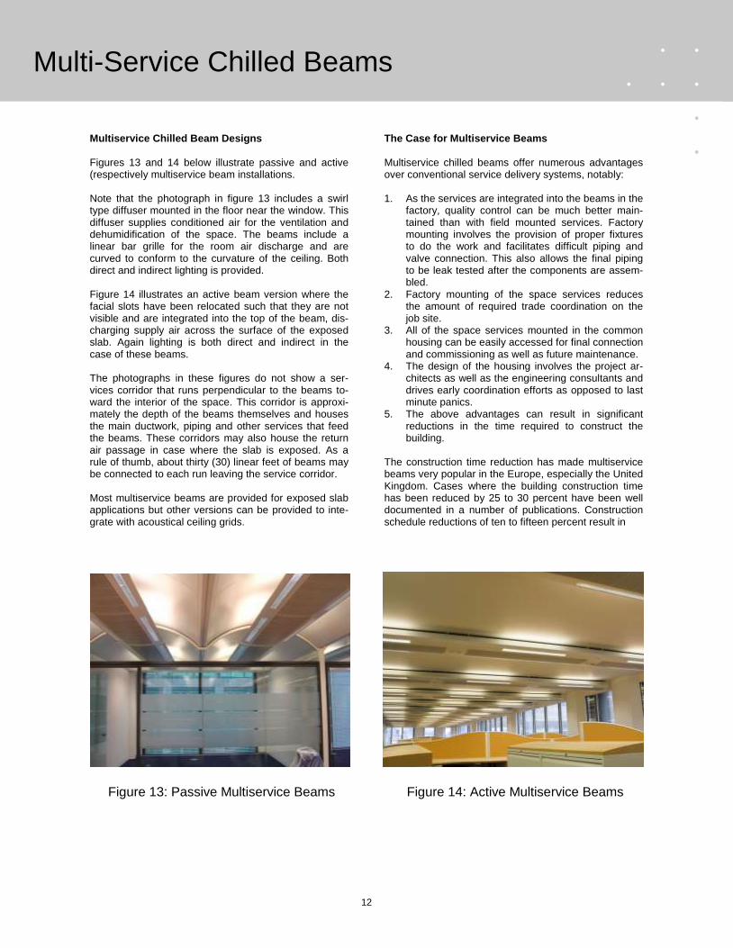
Multiservice Chilled Beam Designs Figures 13 and 14 below illustrate passive and active (respectively multiservice beam installations. Note that the photograph in figure 13 includes a swirl type diffuser mounted in the floor near the window. This diffuser supplies conditioned air for the ventilation and dehumidification of the space. The beams include a linear bar grille for the room air discharge and are curved to conform to the curvature of the ceiling. Both direct and indirect lighting is provided. Figure 14 illustrates an active beam version where the facial slots have been relocated such that they are not visible and are integrated into the top of the beam, dis-charging supply air across the surface of the exposed slab. Again lighting is both direct and indirect in the case of these beams. The photographs in these figures do not show a ser-vices corridor that runs perpendicular to the beams to-ward the interior of the space. This corridor is approxi-mately the depth of the beams themselves and houses the main ductwork, piping and other services that feed the beams. These corridors may also house the return air passage in case where the slab is exposed. As a rule of thumb, about thirty (30) linear feet of beams may be connected to each run leaving the service corridor. Most multiservice beams are provided for exposed slab applications but other versions can be provided to inte-grate with acoustical ceiling grids.
The Case for Multiservice Beams Multiservice chilled beams offer numerous advantages over conventional service delivery systems, notably: 1. As the services are integrated into the beams in the
factory, quality control can be much better main-tained than with field mounted services. Factory mounting involves the provision of proper fixtures to do the work and facilitates difficult piping and valve connection. This also allows the final piping to be leak tested after the components are assem-bled.
2. Factory mounting of the space services reduces the amount of required trade coordination on the job site.
3. All of the space services mounted in the common housing can be easily accessed for final connection and commissioning as well as future maintenance.
4. The design of the housing involves the project ar-chitects as well as the engineering consultants and drives early coordination efforts as opposed to last minute panics.
5. The above advantages can result in significant reductions in the time required to construct the building.
The construction time reduction has made multiservice beams very popular in the Europe, especially the United Kingdom. Cases where the building construction time has been reduced by 25 to 30 percent have been well documented in a number of publications. Construction schedule reductions of ten to fifteen percent result in
Figure 13: Passive Multiservice Beams Figure 14: Active Multiservice Beams

13
Multi-Service Chilled Beams
significant cost savings. In particular, fixed site costs can be retired much earlier. These fixed site costs include but are not limited to: 1. Communication and utilities services 2. Sanitation services 3. Equipment rentals 4. Insurance costs On a job with a two year construction schedule, these fixed costs (which contribute nothing to the value of the project) typically amount to 12 to 14% of the value of the construction itself. Terminating the project sooner allows these costs to be cut proportionally. The use of multiservice beams can also allow the elimination of the acoustical ceiling system and, on new construction projects, may afford the use of lesser slab spacing. This may reduce the structure costs as well or may allow more floors to be housed within in a similar structure height (see next section). Finally, earlier completion allows the building owner to begin realizing revenue faster. The combination of these financial impacts typically offsets the cost differ-ence between the multiservice approach and that of conventional HVAC and space services delivery.
Building Height Requirements Multiservice beams may also afford opportunities for reduced building height and/or facilitate the retrofit of buildings with limited slab spacing. The integration of space services in the beam often eliminates the need for an acoustical ceiling and allows the beams to be pendant mounted directly to the structural slab. Figure 15 below illustrates the slab spacing require-ments of a VAV system with fan powered terminals versus an exposed mounted multiservice active chilled beam. The ductwork in the VAV system is must be located such it remains below the horizontal structural supports. It also must be supported several inches above the ceiling grid to allow the installation of light fixtures and sprinkler systems. In order to pro-vide a floor to ceiling height of nine (9) feet, the slab spacing is typically thirteen (13) feet. Multiservice beams which are mounted to the slab allow the provision of a ten (10) foot distance from the floor to the overhead slab while maintaining an 8.5 foot clearance under the beams when used with a 10.5 foot slab spacing. This savings essentially allows the addition twenty percent more floors in a building when multiservice beams are used instead of a VAV system.
Suspended ceiling
13'-0" 9'-0"
VAV with Fan Terminals
Light fixture
10'-0" 8'-6"
Multiservice Chilled Beams
10'-6"
Figure 15: Slab Spacing Reduction with Multiservice Beams

14
Comfort Considerations
CHILLED BEAM SYSTEM DESIGN GUIDELINES The HVAC system is responsible for three important tasks that help assure occupant comfort and a healthy indoor environment:
1) Removal of the space sensible heat gains. 2) Delivery of a prescribed volume flow rate of
outdoor air to properly ventilate the space. 3) Sufficient dehumidification to offset the space
latent heat gains. As the water circuit in chilled beams is designed only to assist in achieving the sensible cooling objective, the air supply to the space must be properly maintained to accomplish the ventilation and dehumidification goals. In order to achieve efficient chilled beam system operation, certain considerations should be factored into the development of the system design and operational objectives. The following sections identify and briefly discuss such considerations that apply to the design, selection and specification of the equipment that supplies and controls the chilled beams.
• General design objectives. • Air-side design goals and considerations. • Water-side design goals and considerations. • Control and operational considerations.
The following sections discuss design decisions that affect the sizing and selection of the air and water system equipment and accessories. Designing for occupant thermal comfort The maintenance of a high level of occupant thermal comfort is the primary objective of most chilled beam applications. ANSI/ASHRAE Standard 55-2004 Thermal Environmental Conditions for Human Occupancy 2 identifies key factors that contribute to thermal comfort and defines environmental conditions that are likely to produce such. The Standard generally states that dur-ing cooling operation, the space (operative) dry bulb temperature should be maintained between 68 and 77˚F and the space dew point temperature should not exceed 60.5˚F. If the space operative temperature is 75˚F, this maximum dew point temperature corresponds to a relative humidity of 60%. The Standard also defines the occupied zone as the portion of the bounded by the floor and the head level of the predominant stationary space occupants (42 inches if seated, 72” if standing) and no closer than 3 feet from outside walls/windows or 1 foot from internal walls. It is generally accepted that velocities within the occupied zone should not exceed 50 to 60 feet per minute.
Designing for acceptable space acoustical levels The space acoustical requirements are usually dictated by its intended use. The 2007 ASHRAE Handbook (Applications)3 prescribes design guidance (including recommended space acoustical levels) for various types of facilities and their use.
AIR SIDE DESIGN CONSIDERATIONS Room and primary air design considerations When chilled beam systems are being contemplated, the relationship between the room design conditions and the primary air requirements should be closely evaluated. As previously stated, the chilled water circuit within chilled beams is capable of considerably higher sensible heat removal efficiencies than does conditioned air supplied to the space. As such, it is advantageous to remove as much sensible heat as possible by means of the chilled water circuit. In theory, this practice would allow the supply airflow rate to the space to be reduced proportionally and result in both energy savings and reduced HVAC services space requirements. However, the airflow supply to the space is also the sole source of space ventilation and dehu-midification so consideration of these functions is im-perative in the design of chilled beam systems. The primary (conditioned) airflow rate to the beam must be sufficient to provide space humidity control, ventilation and supplement the chilled water circuit in satisfying the space sensible heat gains. The space primary airflow rate must be the maximum of that needed to adequately accomplish all of those individual tasks. Space ventilation requirements are usually based on the number of space occupants and the floor area in which they reside. ASHRAE Standard 62-2004 provides guidance in the calculation of these requirements. Some spaces (laboratories, healthcare facilities, etc.) may require higher ventilation rates due to processes they support. Identification of the re-quired space ventilation rate should be the first step in the design process. a
15
Airside Design Consideration
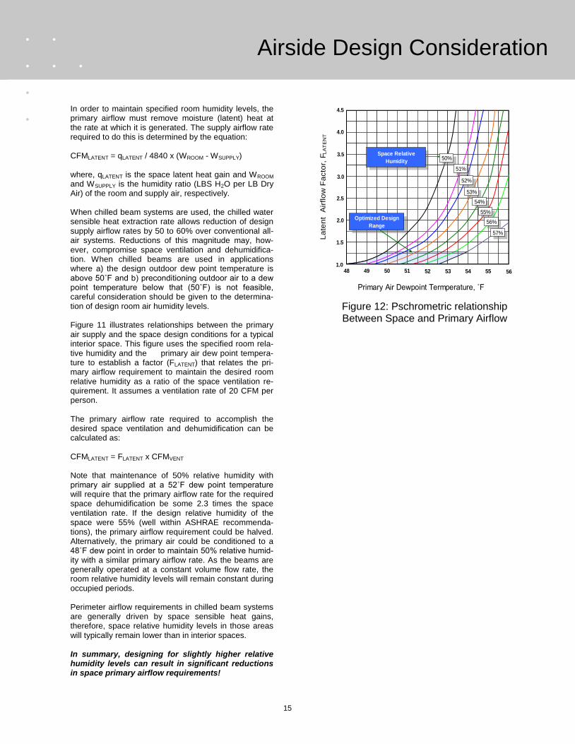
In order to maintain specified room humidity levels, the primary airflow must remove moisture (latent) heat at the rate at which it is generated. The supply airflow rate required to do this is determined by the equation: CFMLATENT = qLATENT / 4840 x (WROOM - WSUPPLY) where, qLATENT is the space latent heat gain and WROOM and WSUPPLY is the humidity ratio (LBS H2O per LB Dry Air) of the room and supply air, respectively. When chilled beam systems are used, the chilled water sensible heat extraction rate allows reduction of design supply airflow rates by 50 to 60% over conventional all-air systems. Reductions of this magnitude may, how-ever, compromise space ventilation and dehumidifica-tion. When chilled beams are used in applications where a) the design outdoor dew point temperature is above 50˚F and b) preconditioning outdoor air to a dew point temperature below that (50˚F) is not feasible, careful consideration should be given to the determina-tion of design room air humidity levels. Figure 11 illustrates relationships between the primary air supply and the space design conditions for a typical interior space. This figure uses the specified room rela-tive humidity and the primary air dew point tempera-ture to establish a factor (FLATENT) that relates the pri-mary airflow requirement to maintain the desired room relative humidity as a ratio of the space ventilation re-quirement. It assumes a ventilation rate of 20 CFM per person. The primary airflow rate required to accomplish the desired space ventilation and dehumidification can be calculated as: CFMLATENT = FLATENT x CFMVENT Note that maintenance of 50% relative humidity with primary air supplied at a 52˚F dew point temperature will require that the primary airflow rate for the required space dehumidification be some 2.3 times the space ventilation rate. If the design relative humidity of the space were 55% (well within ASHRAE recommenda-tions), the primary airflow requirement could be halved. Alternatively, the primary air could be conditioned to a 48˚F dew point in order to maintain 50% relative humid-ity with a similar primary airflow rate. As the beams are generally operated at a constant volume flow rate, the room relative humidity levels will remain constant during occupied periods. Perimeter airflow requirements in chilled beam systems are generally driven by space sensible heat gains, therefore, space relative humidity levels in those areas will typically remain lower than in interior spaces. In summary, designing for slightly higher relative humidity levels can result in significant reductions in space primary airflow requirements!
A
Primary Air Dewpoint Termperature, ˚F
48 49 50 51 52 53 54 551.0
2.0
3.0
4.0
La
ten
t A
irflo
w F
acto
r, F
LA
TE
NT
1.5
2.5
3.5
4.5
56
Space Relative
Humidity
Optimized Design
Range
50%
51%
52%
53%
54%
55%
56%
57%
Figure 12: Pschrometric relationship Between Space and Primary Airflow
16
Airside Design Considerations
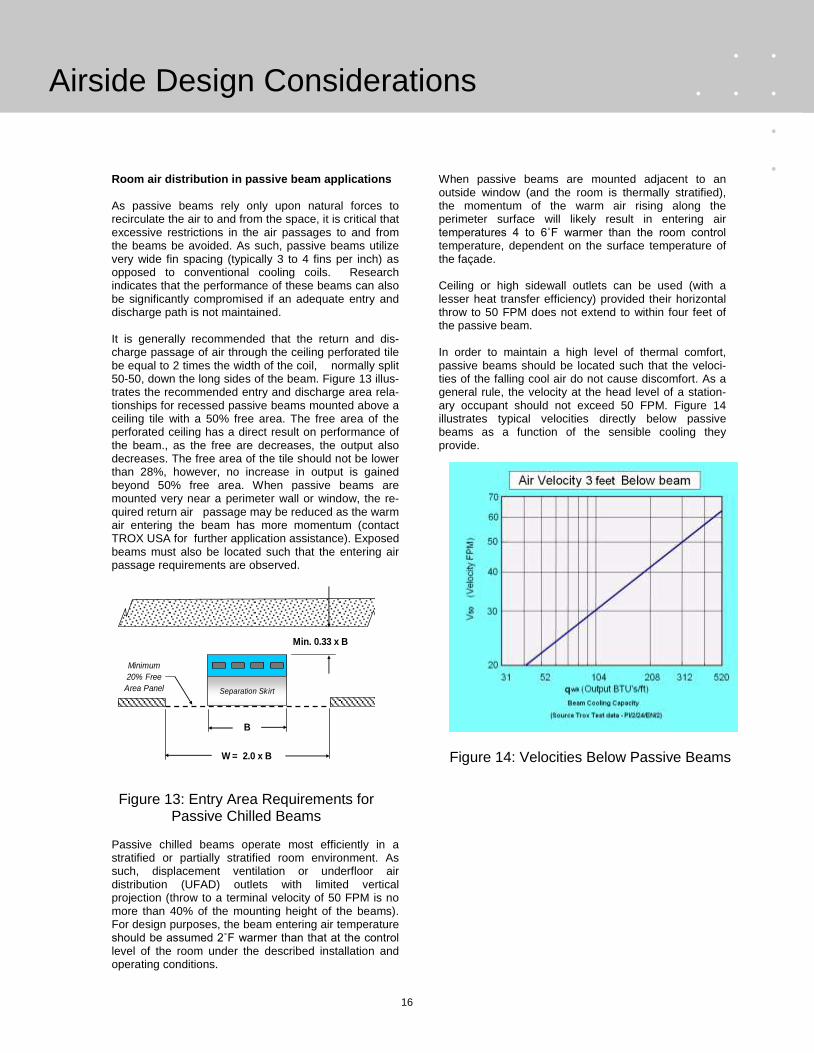
Room air distribution in passive beam applications As passive beams rely only upon natural forces to recirculate the air to and from the space, it is critical that excessive restrictions in the air passages to and from the beams be avoided. As such, passive beams utilize very wide fin spacing (typically 3 to 4 fins per inch) as opposed to conventional cooling coils. Research indicates that the performance of these beams can also be significantly compromised if an adequate entry and discharge path is not maintained. It is generally recommended that the return and dis-charge passage of air through the ceiling perforated tile be equal to 2 times the width of the coil, normally split 50-50, down the long sides of the beam. Figure 13 illus-trates the recommended entry and discharge area rela-tionships for recessed passive beams mounted above a ceiling tile with a 50% free area. The free area of the perforated ceiling has a direct result on performance of the beam., as the free are decreases, the output also decreases. The free area of the tile should not be lower than 28%, however, no increase in output is gained beyond 50% free area. When passive beams are mounted very near a perimeter wall or window, the re-quired return air passage may be reduced as the warm air entering the beam has more momentum (contact TROX USA for further application assistance). Exposed beams must also be located such that the entering air passage requirements are observed.
Passive chilled beams operate most efficiently in a stratified or partially stratified room environment. As such, displacement ventilation or underfloor air distribution (UFAD) outlets with limited vertical projection (throw to a terminal velocity of 50 FPM is no more than 40% of the mounting height of the beams). For design purposes, the beam entering air temperature should be assumed 2˚F warmer than that at the control level of the room under the described installation and operating conditions.
When passive beams are mounted adjacent to an outside window (and the room is thermally stratified), the momentum of the warm air rising along the perimeter surface will likely result in entering air temperatures 4 to 6˚F warmer than the room control temperature, dependent on the surface temperature of the façade. Ceiling or high sidewall outlets can be used (with a lesser heat transfer efficiency) provided their horizontal throw to 50 FPM does not extend to within four feet of the passive beam. In order to maintain a high level of thermal comfort, passive beams should be located such that the veloci-ties of the falling cool air do not cause discomfort. As a general rule, the velocity at the head level of a station-ary occupant should not exceed 50 FPM. Figure 14 illustrates typical velocities directly below passive beams as a function of the sensible cooling they provide.
B
W = 2.0 x B
Min. 0.33 x B
Separation Skirt
Minimum
20% Free
Area Panel
Figure 13: Entry Area Requirements for Passive Chilled Beams
Figure 14: Velocities Below Passive Beams

17
Airside Design Considerations
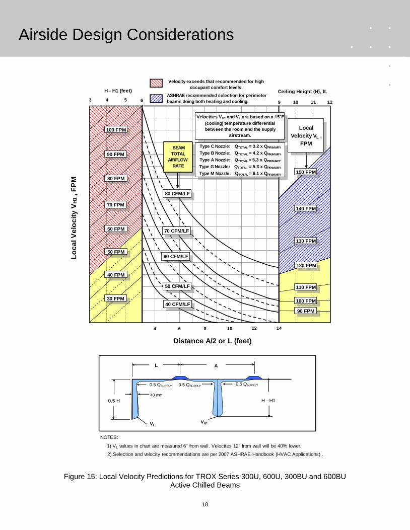
Space temperature control in passive beam systems is accomplished by varying the amount of sensible heat removed by the chilled water. The chilled water supply to several beams within a single zone is generally controlled by a single chilled water valve. Although the zone may consist of multiple spaces, a certain degree of temperature compensation for each space will be affected by the passive beam itself. As the cooling requirement of the space is reduced, the temperature of the air entering the beam will also be reduced. This will result in less heat transfer to the water circuit and a lower return water temperature. Passive chilled beams cannot be used for heating as its airflow would be reversed. They are typically applied with some type of separate heating system such as low level finned tube heaters. Radiant (ceiling or wall mounted) heating panels can also be used depending on the façade heat losses expected. Thermal comfort considerations with active beams While the primary (conditioned) airflow rate for active chilled beams can be greatly reduced, their induction ratios (2 to 6 CFM of room air per CFM primary air) result in discharge airflow rates that are slightly higher than those of conventional all-air systems. As such, attention should be exercised in the beam placement to avoid drafty conditions and maximize occupant thermal comfort. Figure 15 predicts maximum occupied zone velocities for various combinations of primary airflow rates and active beam spacing. This nomograph suggests local velocities which will maintain acceptable levels of occupant comfort per ASHRAE. As the room air distribution provided by active beams is identical to that provided by ceiling slot diffusers, their selection for (total) discharge airflow rates greater than 40 CFM per linear foot of slot is not recommended when high levels of occupant thermal comfort are required! The vL velocities shown in figure 15 are those predicted within 2 inches of the window or wall surface during cooling operation. It is recommended that beams which are configured for both heating and cooling of perimeter spaces be selected such that vL (selected for cooling operation) is between 120 and 150 FPM in order to assure that the warm air is adequately projected down the perimeter surface. Velocities taken 6 inches away from the surface can be expected to be about half those values. Heating in chilled beam applications Ceiling or high sidewall mounted passive chilled beams exert no motive force on their discharge airflow, and cannot be used for overhead heating. Heating must be provided by a separate source, either the primary air supply or a separate heating system (finned tube, radiant panel, etc.).
Active beams can be for heat in moderate climates. Hot water can either be delivered to each perimeter area beam or to a hot water heating coil in the duct supply-ing a number of beams within the same thermal control zone. The use of a zone hot water heating coil feeing multiple chilled beams is a generally more economic option than piping each chilled beam for heating as it may save considerable labor and piping material costs. If active chilled beams are used for heating, the follow-ing recommendations should be observed:
• Chilled beam discharge temperatures should be maintained within 15˚F of the room temperature.
• Velocities at the mid-level of outside walls and windows should be maintained within the region indicated in figure 15.
Unoccupied periods demanding heating via the chilled beams or primary air system will require that the AHU remain operational. Variable air volume operation using active beams Although normally operated as constant air volume delivery devices, active chilled beams can also be used as variable air volume (VAV) devices. VAV operation may be advantageous when space occupancy and/or ventilation demands vary widely. Recommendations for the control of chilled beams in VAV applications can be found in the control section of this document.
18
Airside Design Considerations
Distance A/2 or L (feet)
Velocity exceeds that recommended for high
occupant comfort levels.
Lo
ca
l V
elo
cit
y V
H1 , F
PM
63 4 5
H - H1 (feet)
40 FPM
30 FPM
70 FPM
60 FPM
50 FPM
80 FPM
90 FPM
100 FPM
9 10 11
Ceiling Height (H), ft.
6 8 10 12 144
60 CFM/LF
70 CFM/LF
80 CFM/LF
12
BEAM
TOTAL
AIRFLOW
RATE
ASHRAE recommended selection for perimeter
beams doing both heating and cooling.
Velocities VH1 and VL are based on a 15˚F
(cooling) temperature differential
between the room and the supply
airstream.
Type C Nozzle: QTOTAL = 3.2 x QPRIMARY
Type B Nozzle: QTOTAL = 4.2 x QPRIMARY
Type A Nozzle: QTOTAL = 5.3 x QPRIMARY
Type G Nozzle: QTOTAL = 5.3 x QPRIMARY
Type M Nozzle: QTOTAL = 6.1 x QPRIMARY
Local
Velocity VL ,
FPM
H - H1
AL
VH1VL
40 mm
0.5 QSUPPLY0.5 QSUPPLY 0.5 QSUPPLY
150 FPM
140 FPM
130 FPM
120 FPM
110 FPM
100 FPM
90 FPM
0.5 H
50 CFM/LF
40 CFM/LF
NOTES:
1) VL values in chart are measured 6" from wall. Velocites 12" from wall will be 40% lower.
2) Selection and velocity recommendations are per 2007 ASHRAE Handbook (HVAC Applications) .
Figure 15: Local Velocity Predictions for TROX Series 300U, 600U, 300BU and 600BU Active Chilled Beams

19
Water Side Design Considerations
WATER SIDE DESIGN CONSIDERATIONS Once the room air conditions have been established, the water side design objectives and requirements can be identified. Certain factors must be considered in arriving at the chilled water system design. The following sections discuss these. Chilled water supply source There are several possible sources of adequately conditioned chilled water for the supply of chilled beam systems. Among these are several sources discussed below:
• Return water from AHU chilled water coil • Dedicated chilled water supply system • District chilled water supply • Geothermal wells
When air handling units associated with chilled beam systems utilize chilled water evaporator coils, their return water can often be used to remove heat from the chilled beam circuit. Figure 16 illustrates a chilled water loop whose heat is extracted through a heat exchanger to the AHU return water loop. The chilled water supply is a closed loop which includes a bypass by which return water can be bypassed around the heat exchanger to maintain the desired chilled water supply temperature to the beams. Figure 17 illustrates a chilled beam system where the beams are supplied by a dedi-cated chiller. The chilled water loop allows the chiller to operate at a higher efficiency due to the higher return water temperatures associated with the chilled beam system. The chiller‟s COP can often be increased by 25 to 30% by doing so. In some cases, water from district chilled water supplies or geothermal wells may replace the return water from the AHU and serve as the primary loop in the heat exchanger shown in figure 16. Chilled water supply and return temperatures The most important decision regarding the chilled water system involves the specification of a chilled water supply temperature. In order to prevent condensation from forming on the beams, the chilled water supply temperature must be sufficiently maintained. The REHVA Chilled Beam Applications Guidebook1 suggests that condensation will first occur on the supply piping entering the beam. As such, it is very important to insulate the chilled water supply piping to the beams. Reference 4 suggests that condensation will not likely form when the active chilled water supply temperature is maintained no lower than 3˚F below the room air dew point and at least 1˚F above the space dew point temperature in the case of passive beams.
TROX USA recommends that the chilled water sup-ply temperature for passive chilled beams is at least 1˚F above the maximum room dew point that can be controlled to whilst active beams are kept at or above the room dew point as an operational safety margin. In general, most beams installed to date have a supply temperature 1.5˚F or more above room dew point. The return water temperature leaving chilled beams is at least 3˚F higher than the chilled water supply. As such, the chilled water return piping does not normally need to be insulated.
T
Supply Temperature
Controller
Chilled Water
Pump
3-way
Moduating
Valve
Return Water Bypass
Primary Chilled
Water Supply
Secondary
(Tempered) Chilled
Water Supply to
Beams
HEAT EXCHANGER
Secondary
Chilled Water
Return
Primary Chilled
Water Return
T
Supply Temperature
Controller
Chilled Water
Pump
3-way
Moduating
Valve
Return Water Bypass
Secondary
Chilled Water
Return
Storage
Vessel
Dedicated
Chiller
Secondary
(Tempered) Chilled
Water Supply to
Beams
Figure 15: Shared or Tempered Chilled Water Supply Circuit
Figure 16: Dedicated Chilled Water Circuit

20
Water Side Design Considerations
Hot water supply and return temperatures Active chilled beams can be used for perimeter heating and cooling in mild climates. It is recommended that the hot water supply be maintained at a temperature that will result in a beam discharge temperature no more than15˚F warmer than the ambient room temperature. Water flow rates There are factors that affect the minimum and maximum water flow rates within the chilled beam system. Maximum flow rates are limited by the pressure loss within the beam. Minimum flow rates are based on the maintenance of turbulent flow to assure proper heat transfer. The following recommendations apply to the chilled water system design:
Water head loss through the beams should be limited to 10 feet H2O or less. Pressures exceeding 10 feet H2O at the water con-trol valve may cause noise when the valve begins opening. The 2005 ASHRAE Handbook (Fundamentals)5
limits water flow rates in pipes that are two (2) inches in diameter or less to that which results in maximum velocities of 4 FPS. Chilled beam water flow rates below 0.15 GPM may result in non-turbulent flow. Selection below this flow rate should not be made as the coil per-formance cannot be assured.
Water treatment recommendations As most of the elements within the chilled (and hot) water piping systems are typically copper or brass, it is important that the water circuit is treated to assure that there are no corrosive elements in the water. The water circuits feeding the chilled beams should also be treated with a sodium nitrite and biocide solutions to prevent bacterial growth. Glycol should not be added except where absolutely necessary as it changes the specific capacity of the chilled water and its effect on the chilled beam performance must be estimated and accounted for. Prior to start up and commissioning, all chilled and hot water piping should be flushed for contaminants.

21
Control Strategies
CHILLED BEAM CONTROL CONSIDERATIONS This section discusses the control of both the air and the water supply in chilled beam systems. It also presents and discusses strategies for condensation prevention. Temperature control and zoning with chilled beams Room temperature control is primarily accomplished by varying the water flow rate or its supply temperature to the chilled beam coils in response to a zone thermostat signal. Modulation of the chilled water flow rate typically produces a 7 to 8˚F swing in the beam‟s supply air temperature, which affects a 50 - 60% turndown in the beam‟s sensible cooling rate. This is usually suffi-cient for the control of interior spaces (except confer-ence areas) where sensible loads do not tend to vary significantly. If additional reduction of the space cooling is required, the primary air supply to the beam can be reduced. In any case, modulation of the chilled water flow rate or temperature should be the primary means for controlling room temperature as it has little or no effect on space ventilation and/or dehumidification. Only after the chilled water flow has been discontinued should the primary airflow rate be reduced. Thermal control zones for chilled beam applications should be establish in precisely the same manner they are defined for all air systems. These zones should consist of adjacent spaces whose sensible cooling requirements are similar, and several beams should be controlled from a single space thermostat. For example, the beams serving several perimeter spaces with the same solar exposure can be controlled by a single thermostat to create a zone of similar size to that which might be served by a single fan terminal in an all air system. Conference rooms and other areas with widely varying occupancy should be controlled separately. Control of the primary airflow rate Figure 17 illustrates a TROX model VFL flow limiter which can be fitted directly to the inlet side of the active beam. This limiter is fully self-contained and requires no power or control connections. It may be field set to maintain a volume flow rate to the beam. VFL limiters are recommended for use on beams fed by the same air handling unit supplying VAV terminals. The VFL compensates for system pressure changes to maintain the beam‟s design airflow rate. Figure 18 illustrates this application. VFL flow limiters require a minimum of 0.15 inches H2O differential static pressure to operate. This must be added to the catalogued pressure loss of the beam to arrive at an appropriate inlet static pressure require-ment. For acoustical reasons, the inlet static pressure should not exceed 1.0 inches H2O. More information on VFL flow limiters may be found in TROX leaflet 5/9.2/EN/3.
Chilled (and hot) water flow control strategies The most economical way to control the output of the chilled beam is to modulate the water flow rate through the coil. This may be accomplished in either of two ways. Figure 19 illustrates a typical piping and hydronic control schematic for a single thermal zone utilizing chilled beams. There are isolation valves within each zone which allow the chilled beam coils within the zone to be isolated from the chilled water system. This enables beams to be relocated or removed without disturbing the water flow in other zones. The coils‟ water flow rate is throttled by a 2-way chilled water valve actuated by the zone thermostat. Most chilled beam systems utilize floating point valve actuators that provide on-off control of the beam water flow. Throttling the water flow rate results in variable volume flow through the main water loop while its supply and return water temperatures tend to remain relatively constant.
Figure 20 shows a zone within a chilled beam system that is controlled by a 3-way valve. Such a schematic will allow modulation of the chilled water flow to the beams within the zone while maintaining a constant volume flow rate within the main distribution system. Such control may be advantageous in cases where a dedicated chiller is used and significant variations in the water flow rate can result in danger of freezing within the chiller itself. Three way valves are also frequently used when condensation prevention controls are employed. The piping illustrated in figure 19 is reverse-return. The first unit supplied with chilled water is the farthest from the main chilled water return. Using reverse-return
Figure 18: TROX VFL Flow Controller

22
Control Strategies
Chilled beams within a single thermal zone
Chilled
water
supply
Chilled
water
return
Isolation
valve
2 way
on-off
control
valve
T Zone thermostat
Isolation
valve
Chilled beams within a single thermal zone
Chilled
water
supply
Chilled
water
return
Isolation
valves (2)
3 way
proportional
control
valve
T Zone thermostat
Flow
Measurement
and Balancing
Valves
Chilled beams within a single thermal zone
Chilled
water
supply
Chilled
water
return
Isolation
valves (2)
3 way proportional
control valve
TZone thermostat
Pump
Figure 19: Chilled Beam Zone Control by Means of a Throttling (On/Off) 2 Way Valve
Figure 20: Chilled Beam Zone Control by Means of a Diverting 3 Way Valve
Figure 21: Chilled Beam Zone Control by Water Temperature Modulation
23
Control Strategies
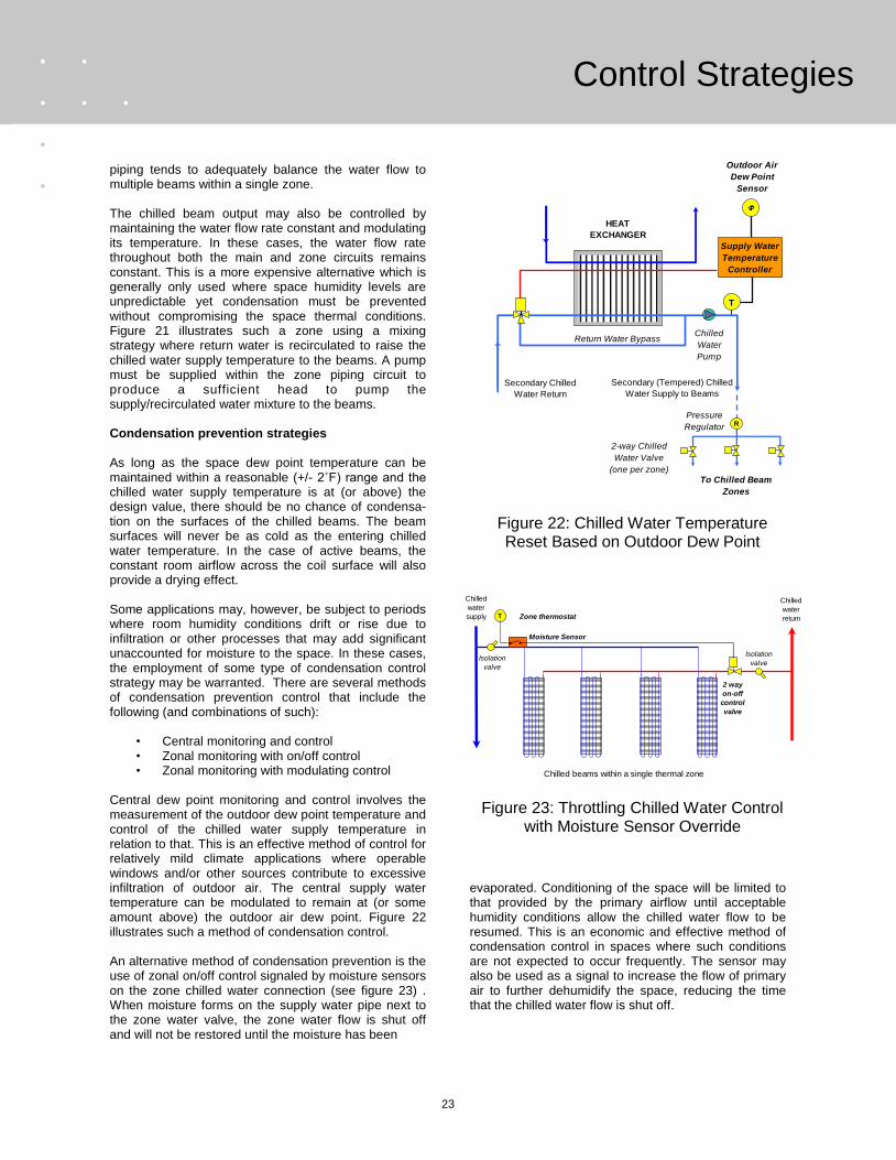
piping tends to adequately balance the water flow to multiple beams within a single zone. The chilled beam output may also be controlled by maintaining the water flow rate constant and modulating its temperature. In these cases, the water flow rate throughout both the main and zone circuits remains constant. This is a more expensive alternative which is generally only used where space humidity levels are unpredictable yet condensation must be prevented without compromising the space thermal conditions. Figure 21 illustrates such a zone using a mixing strategy where return water is recirculated to raise the chilled water supply temperature to the beams. A pump must be supplied within the zone piping circuit to produce a sufficient head to pump the supply/recirculated water mixture to the beams. Condensation prevention strategies As long as the space dew point temperature can be maintained within a reasonable (+/- 2˚F) range and the chilled water supply temperature is at (or above) the design value, there should be no chance of condensa-tion on the surfaces of the chilled beams. The beam surfaces will never be as cold as the entering chilled water temperature. In the case of active beams, the constant room airflow across the coil surface will also provide a drying effect. Some applications may, however, be subject to periods where room humidity conditions drift or rise due to infiltration or other processes that may add significant unaccounted for moisture to the space. In these cases, the employment of some type of condensation control strategy may be warranted. There are several methods of condensation prevention control that include the following (and combinations of such):
• Central monitoring and control • Zonal monitoring with on/off control • Zonal monitoring with modulating control
Central dew point monitoring and control involves the measurement of the outdoor dew point temperature and control of the chilled water supply temperature in relation to that. This is an effective method of control for relatively mild climate applications where operable windows and/or other sources contribute to excessive infiltration of outdoor air. The central supply water temperature can be modulated to remain at (or some amount above) the outdoor air dew point. Figure 22 illustrates such a method of condensation control. An alternative method of condensation prevention is the use of zonal on/off control signaled by moisture sensors on the zone chilled water connection (see figure 23) . When moisture forms on the supply water pipe next to the zone water valve, the zone water flow is shut off and will not be restored until the moisture has been
evaporated. Conditioning of the space will be limited to that provided by the primary airflow until acceptable humidity conditions allow the chilled water flow to be resumed. This is an economic and effective method of condensation control in spaces where such conditions are not expected to occur frequently. The sensor may also be used as a signal to increase the flow of primary air to further dehumidify the space, reducing the time that the chilled water flow is shut off.
T
R
To Chilled Beam
Zones
Pressure
Regulator
Supply Water
Temperature
Controller
Chilled
Water
Pump
Return Water Bypass
2-way Chilled
Water Valve
(one per zone)
Secondary (Tempered) Chilled
Water Supply to Beams
HEAT
EXCHANGER
Secondary Chilled
Water Return
Outdoor Air
Dew Point
Sensor
Chilled
water
supply
Chilled beams within a single thermal zone
Chilled
water
return
Isolation
valve
2 way
on-off
control
valve
T Zone thermostat
Isolation
valve
Moisture Sensor
Figure 23: Throttling Chilled Water Control with Moisture Sensor Override
Figure 22: Chilled Water Temperature Reset Based on Outdoor Dew Point

24
Installation and Commissioning
If the maintenance of local thermal conditions is critical, a zone humidistat may be used to modulate the zone chilled water supply temperature as shown in figure 24. This requires that each zone fitted for such control be fitted with a pump capable of recirculating return water into the supply circuit of the chilled beam.
INSTALLATION AND COMMISSIONING Mounting considerations The weight of chilled beams requires that they be separately supported, independent of any integrated ceiling grid or drywall surface. They are usually suspended from the structure above by means of threaded rods or other sufficiently strong support means that allow the beam‟s position to be vertically adjusted. The beams are usually mounted and connected prior to the installation of the ceiling grid or drywall. TROX chilled beams are furnished with a minimum of four (4) attachment angles whose position can be adjusted along the beam length to allow the beam to be “dropped” into the suspended ceiling grid with which it is integrated. When integrated with a ceiling grid system or drywall, it is recommended that the beams be suspended from linear channels (such as uni-strut) that run perpendicular to the beam‟s length, so there is some adjustability in every direction. Figure 25 illustrates the mounting of active and passive beams. TROX offers various borders to coordinate DID series beams with three types of acoustical ceiling grids (illustrated in figure 26):
Chilled beams within a single thermal zone
Chilled
water
supply
Chilled
water
return
Isolation
valves
(2)
3 way
proportional
control valve
T
Zone Temperature
and Humidity
Controller
Pump
Temperature
Sensor
Dew Point
Sensor
Figure 24: Condensation Protection Using Temperature/Humidity Sensing to Modulate
the Zone Chilled Water Temperature
Uni-strut Channels
bolted to structure
above allows
adjustment along
beam width
Beam suspended
from channels by
threaded rods
Factory furnished
mounting brackets
allow adjustment
along beam length
Figure 25: Installation of an Active Beam
9/16"
5/16"
9/16"
1"
Integration with
standard 1" wide
(inverted) tee bar grid
Integration with narrow
9/16" wide (inverted)
tee bar grid
Integration with narrow
9/16" wide tubular type
grid
Integration into dry wall
ceiling using plaster
frame
1"
Figure 26: Integration of Active Beams into Common Ceiling System Applications

25
Installation and Commissioning
When active beams are to be used without an adjacent ceiling surface, TROX recommends that an extended outer surface be furnished which allows formation of a Coanda effect that helps direct the discharge air horizontally and prevent dumping. Recessed passive chilled beams may also be integrated with suspension grid systems, but they are usually mounted above the grid and have no direct interaction with it. It is recommended that a separation skirt (see figure 13) be used to separate the two air streams (warm entering air from cool discharge air) of the beam. Exposed passive beams are almost always pendant mounted to the structural slab above and used without a false ceiling system. Air and water connections Connection of the chilled water (and hot water where applicable) supplies to chilled beams are the responsibility of the installing contractor. Chilled beams may be furnished with either NPT (threaded) male con-nections or with straight pipe ends appropriate for field soldering. While each coil is factory tested for leakage, it is important that the beams are at no time subjected to installation or handling that might result in bending or otherwise damaging the pipe connections in any way. All control, balancing and shut –off valves that may be necessary are also to be provided and installed by others. Do not over tighten any threaded connections to the beams. All chilled water supply piping should be adequately insulated. Return water piping may be left un-insulated provided the return water temperature remains above the dew point of the spaces over which it passes. Flexible hoses may be used for chilled beam water connections. These hoses may employ either threaded or snap lock connectors. TROX USA offers such threaded connectors as an option. These connectors are 100% tested and marked with individual identification numbers. In the event of a failure, the batch within which they were manufactured can be readily identified and preemptive remediation can be performed without concern that all hoses on the job are subject to failure soon. The normal life of flexible hoses exceeds fifteen year but can be affected by (among other things) swings in their operational temperature and lack of sufficient water treatment. The connection of the primary air supply duct to active chilled beams is also the responsibility of the installing contractor. This connection should include the provision of at least eight (8) inches of straight sheet metal duct connected directly to the beam‟s primary air inlet. No more than five (5) feet of flexible duct should be used to a
connect the beam to the supply air duct and this flexible duct should not have any excess bends or radius. Water treatment It is imperative that there are no corrosive elements in the secondary water supply to the beams as there are brass fittings on the coils and/or connection hoses. Periodic testing of the secondary water circuit on each floor should be performed to assure that none of these corrosive elements are present. Prior to connection to the beams and the chiller plant, the water pipes should be thoroughly flushed to remove any impurities that may reside within them. Only after this purging has occurred should the connections to the coils and the chiller plant be performed. Additional information regarding system cleaning may be found in reference 6. Once filled by the mechanical contractor, the system should be dosed with chemicals that prevent bacterial growth. Typical additives would be a sodium nitrate inhibitor solution of 1000 parts per million (e.g. Nalcol 90) and a biocide solution of 200 parts per million (e.g. Nalcol). Reference 6 provides additional information regarding water treatment. System Commissioning TROX provides each beam with vents that are used to purge air from the water circuit. These vents are located on the coil‟s intended return header. Prior to commissioning any air trapped in the pipe work should be purged from the water circuit through these vents. A flow measuring device and suitable balancing valve should be provided for each beam which will enable adjustment of the chilled water flow rate to each beam within the thermal zone to its design value. This is illustrated in figure 20. Where five to six beams are installed in a reverse-return piping circuit (per figure 19), there will likely be no need for such measuring devices and balancing valves. The primary airflow rate to an active chilled beam can best be determined by measuring the static pressure within the pressurized entry plenum and referring to the calibration chart provided with the beam. TROX provides an integral pressure tap (accessible through the face of the beam) to which a measuring gauge can be connected. Do not attempt to read the total dis-charge airflow rate using a hood or any other device that adds downstream pressure to the beam as it will reduce the amount of induction and as such give false readings.

26
Maintenance
SYSTEM OPERATION AND MAINTENANCE There are certain operational requirements that must observed when chilled beam systems are employed in humid climates. In the event the HVAC system is disabled on nights and/or weekends, the chilled water supply must remain suspended until the primary air supply has properly dehumidified the space. It is recommended that some type of space humidity sensing be used to assure that a proper space dew point temperature has been established prior to starting the delivery of chilled water to the space. If chilled beams are to be used in traffic or lobby areas, it is important that the space be maintained at a positive pressure in order to minimize the infiltration of outdoor air. In the case of lobby areas, the use of revolving doors may be warranted. It is also recommended that the beams not be located near any opening doors or windows in these areas. Maintenance requirements Due to their simplicity and lack of moving parts, chilled beams require little maintenance. In fact, the only scheduled maintenance with chilled beams involves the periodic vacuuming of their coil surfaces. Passive beams generally require that this be done every four to five years. In the case of active beams, such cleaning is only required when the face of the unit return section shows visible dirt. At this time, the primary air nozzles should be visually inspected and any debris or lint removed. In all cases, it is recommended that good filtration be maintained within the air handling unit.
REFERENCES
1. REHVA. 2004. Chilled Beam Application Guidebook.
2. ASHRAE. 2004 Thermal environmental condi t ions for human occupancy. ANSI/ASHRAE Standard 55-2004.
3. ASHRAE. 2007. ASHRAE Handbook-Applications.
4. Energie. 2001. Climatic ceilings technical note: design calculations.
5. ASHRAE. 2005. ASHRAE Handbook-Fundamentals.
6. BSRIA. 1991. Pre-commission cleaning of water systems. BSRIA Application Guide 8/91.
7. ASHRAE. 2004 Ventilation for acceptable indoor air quality. ANSI/ASHRAE Standard 62.1-2004.

27
Passive Beam Selection
CHILLED BEAM SELECTION PASSIVE BEAM SELECTION AND LOCATION Selection and location of passive chilled beams is pri-marily affected by the following parameters:
• Required sensible heat removal • Allowable chilled water supply temperature • Horizontal and vertical space restrictions • Occupant thermal comfort considerations • Architectural considerations
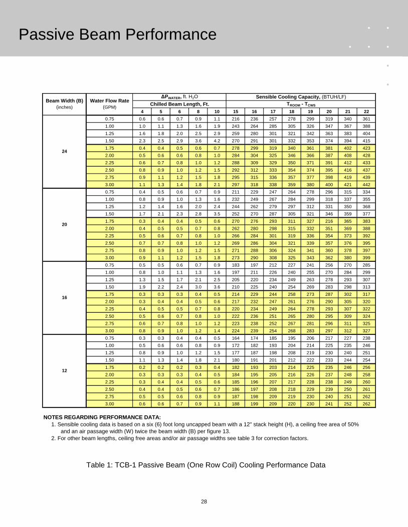
Chilled water supply and return temperatures Before a passive beam selection can be made, it is necessary that an appropriate chilled water supply temperature be identified. TROX USA recommends that the chilled water supply temperature to passive beams be maintained at least 1˚F above the space dew point temperature in order to assure that condensation does not occur. Return water temperatures will generally be 3 to 6˚F higher than the supply water temperature. Water flow rate and pressure loss considerations Water flow velocities in excess of 4 feet per second should be avoided in order to prevent unwanted noise. Design water flow rates below 0.25 gallons per minute are not recommended as laminar flow begins to occur below this flow rate and coil performance may be reduced. Passive chilled beams should also be selected such that their water side head loss does not exceed 10 feet of water. Passive chilled beam performance data The amount of sensible cooling that can be provided by an active chilled beam is dependent on all of the factors listed above. Tables 2 and 3 illustrate the performance of TROX TCB-1 and TCB-2 series passive chilled beams. The available beam widths are listed in the table. The water side pressure loss is illustrated for 4, 6, 8 and 10 foot versions of each beam. The sensible cooling capacity of each beam is expressed in BTUH per linear foot of length for various temperature differentials between entering air and the entering chilled water supply. This capacity is based on a 6 foot beam length, a discharge free area of 50% and an equal inlet free area. It also assumes that the distance between the beam and any obstacle above it is at least 40% the width of the beam. Table 4 presents correction factors for other beam lengths and inlet/discharge conditions. Passive beam selection procedures Selection of passive chilled beams should be performed as follows:
1. Estimate the beam entering air temperature
• If a fully mixed room air distribution system is being used, the entering air temperature will equal the room control temperature.
• If a stratified system is being used, the entering air temperature may be assumed to be 2˚F warmer than the room control temperature.
• When mounted directly above a perimeter window, the entering air temperature can be assumed to be 6˚F warmer than the room temperature.
2. Specify the chilled water supply temperature. 3. Using the temperature difference between the
entering air and chilled water, select a beam whose width and length will remove the required amount of sensible heat.
4. Identify the required water flow rate and
pressure loss for the selected beam. Passive chilled beam selection examples EXAMPLE 1: TCB-1 series passive (recessed type) chilled beams are being used to condition an interior office space that is 120 feet long by 60 feet wide with a sensible heat gain 12 BTUH per square foot. The space is controlled by a thermostat (at the mid-level of the room) for a dry bulb temperature of 76˚F and space RH of 50%. A thermal displacement ventilation system supplies 0.2 CFM per square foot of pretreated ventilation air at 65˚F. SOLUTION: The total sensible heat gain of the space is 8,640 BTUH. The room dew point temperature is 57˚F therefore a chilled water supply temperature of 58˚F will be used. As the displacement ventilation system being used in conjunction with the beams will crate a stratified room environment, the beam entering air temperature (and the return air temperature leaving the space) may be assumed to be 2˚F warmer than the room control t e mp e r a t u r e , o r i n t h i s c a s e 7 8 ˚ F . a
28
Passive Beam Performance
Table 1: TCB-1 Passive Beam (One Row Coil) Cooling Performance Data
4 5 6 8 10 15 16 17 18 19 20 21 22
0.75 0.6 0.6 0.7 0.9 1.1 216 236 257 278 299 319 340 361
1.00 1.0 1.1 1.3 1.6 1.9 243 264 285 305 326 347 367 388
1.25 1.6 1.8 2.0 2.5 2.9 259 280 301 321 342 363 383 404
1.50 2.3 2.5 2.9 3.6 4.2 270 291 301 332 353 374 394 415
1.75 0.4 0.4 0.5 0.6 0.7 278 299 319 340 361 381 402 423
2.00 0.5 0.6 0.6 0.8 1.0 284 304 325 346 366 387 408 428
2.25 0.6 0.7 0.8 1.0 1.2 288 309 329 350 371 391 412 433
2.50 0.8 0.9 1.0 1.2 1.5 292 312 333 354 374 395 416 437
2.75 0.9 1.1 1.2 1.5 1.8 295 315 336 357 377 398 419 439
3.00 1.1 1.3 1.4 1.8 2.1 297 318 338 359 380 400 421 442
0.75 0.4 0.5 0.6 0.7 0.9 211 229 247 264 278 296 315 334
1.00 0.8 0.9 1.0 1.3 1.6 232 249 267 284 299 318 337 355
1.25 1.2 1.4 1.6 2.0 2.4 244 262 279 297 312 331 350 368
1.50 1.7 2.1 2.3 2.8 3.5 252 270 287 305 321 346 359 377
1.75 0.3 0.4 0.4 0.5 0.6 270 276 293 311 327 216 365 383
2.00 0.4 0.5 0.5 0.7 0.8 262 280 298 315 332 351 369 388
2.25 0.5 0.6 0.7 0.8 1.0 266 284 301 319 336 354 373 392
2.50 0.7 0.7 0.8 1.0 1.2 269 286 304 321 339 357 376 395
2.75 0.8 0.9 1.0 1.2 1.5 271 288 306 324 341 360 378 397
3.00 0.9 1.1 1.2 1.5 1.8 273 290 308 325 343 362 380 399
0.75 0.5 0.5 0.6 0.7 0.9 183 197 212 227 241 256 270 285
1.00 0.8 1.0 1.1 1.3 1.6 197 211 226 240 255 270 284 299
1.25 1.3 1.5 1.7 2.1 2.5 205 220 234 249 263 278 293 307
1.50 1.9 2.2 2.4 3.0 3.6 210 225 240 254 269 283 298 313
1.75 0.3 0.3 0.3 0.4 0.5 214 229 244 258 273 287 302 317
2.00 0.3 0.4 0.4 0.5 0.6 217 232 247 261 276 290 305 320
2.25 0.4 0.5 0.5 0.7 0.8 220 234 249 264 278 293 307 322
2.50 0.5 0.6 0.7 0.8 1.0 222 236 251 265 280 295 309 324
2.75 0.6 0.7 0.8 1.0 1.2 223 238 252 267 281 296 311 325
3.00 0.8 0.9 1.0 1.2 1.4 224 239 254 268 283 297 312 327
0.75 0.3 0.3 0.4 0.4 0.5 164 174 185 195 206 217 227 238
1.00 0.5 0.6 0.6 0.8 0.9 172 182 193 204 214 225 235 246
1.25 0.8 0.9 1.0 1.2 1.5 177 187 198 208 219 230 240 251
1.50 1.1 1.3 1.4 1.8 2.1 180 191 201 212 222 233 244 254
1.75 0.2 0.2 0.2 0.3 0.4 182 193 203 214 225 235 246 256
2.00 0.3 0.3 0.3 0.4 0.5 184 195 205 216 226 237 248 258
2.25 0.3 0.4 0.4 0.5 0.6 185 196 207 217 228 238 249 260
2.50 0.4 0.4 0.5 0.6 0.7 186 197 208 218 229 239 250 261
2.75 0.5 0.5 0.6 0.8 0.9 187 198 209 219 230 240 251 262
3.00 0.6 0.6 0.7 0.9 1.1 188 199 209 220 230 241 252 262
Beam Width (B)
(inches)
Water Flow Rate
(GPM)
ΔPWATER, ft. H2O Sensible Cooling Capacity, (BTUH/LF)
Chilled Beam Length, Ft. TROOM - TCWS
24
20
16
12
NOTES REGARDING PERFORMANCE DATA:
1. Sensible cooling data is based on a six (6) foot long uncapped beam with a 12" stack height (H), a ceiling free area of 50%
and an air passage width (W) twice the beam width (B) per figure 13.
2. For other beam lengths, ceiling free areas and/or air passage widths see table 3 for correction factors.

29
Passive Beam Performance
4 5 6 8 10 15 16 17 18 19 20 21 22
0.75 1.8 1.3 1.5 1.7 2.1 153 194 236 277 318 360 401 442
1.00 3.2 2.3 2.6 3.1 3.7 242 283 324 366 407 448 490 531
1.25 5.0 3.6 4.1 4.8 5.8 295 336 377 418 460 501 542 584
1.50 7.2 5.2 5.9 6.9 8.3 330 371 412 454 495 536 577 619
1.75 0.8 0.9 1.0 1.2 1.4 354 396 437 478 520 561 602 643
2.00 1.0 1.1 1.3 1.6 1.9 373 415 456 497 539 580 621 662
2.25 1.3 1.4 1.6 2.0 2.4 387 429 470 511 553 594 635 677
2.50 1.6 1.8 2.0 2.5 2.9 399 440 482 523 564 606 647 688
2.75 1.9 2.2 2.4 3.0 3.5 409 450 491 533 574 615 656 698
3.00 2.3 2.6 2.9 3.6 4.2 417 458 499 541 582 623 665 706
0.75 0.9 1.1 1.2 1.5 1.7 169 204 239 273 308 343 378 413
1.00 1.7 1.9 2.2 2.7 3.1 232 266 301 336 371 406 440 475
1.25 2.6 3.0 3.4 4.2 4.8 267 302 337 372 407 441 476 511
1.50 3.8 4.3 4.9 6.0 6.9 292 326 361 396 431 466 500 535
1.75 0.6 0.7 0.8 1.0 1.1 309 343 378 413 448 483 517 552
2.00 0.8 1.0 1.1 1.3 1.4 322 356 391 426 461 496 530 565
2.25 1.0 1.2 1.4 1.7 1.8 332 366 401 436 471 506 540 575
2.50 1.3 1.5 1.7 2.0 2.2 340 375 409 444 479 514 549 583
2.75 1.6 1.8 2.0 2.5 2.7 346 381 416 451 486 520 555 590
3.00 1.9 2.2 2.4 2.9 3.2 352 387 422 456 491 526 561 596
0.75 0.8 0.9 1.0 1.2 1.4 168 195 221 247 274 300 326 352
1.00 1.4 1.5 1.7 2.2 2.5 202 228 254 281 307 333 360 386
1.25 2.1 2.4 2.7 3.4 3.9 222 249 275 301 327 354 380 406
1.50 3.0 3.4 3.9 4.9 5.7 235 262 288 314 341 367 393 419
1.75 0.5 0.6 0.6 0.8 1.0 245 272 298 324 350 377 403 429
2.00 0.7 0.8 0.8 1.1 1.2 252 279 305 331 358 384 410 437
2.25 0.8 1.0 1.1 1.3 1.6 258 284 311 337 363 389 416 442
2.50 1.0 1.2 1.3 1.6 2.0 262 289 315 341 368 394 420 447
2.75 1.2 1.4 1.6 2.0 2.4 266 292 319 345 371 398 424 450
3.00 1.5 1.7 1.9 2.4 2.8 269 296 322 348 375 401 427 453
0.75 0.6 0.7 0.8 1.1 1.3 153 176 198 221 244 266 289 311
1.00 1.1 1.3 1.5 1.9 2.2 177 199 222 245 267 290 312 335
1.25 1.8 2.0 2.3 3.0 3.5 191 214 237 259 282 304 327 350
1.50 2.5 2.9 3.3 4.3 5.0 201 224 246 269 291 314 337 359
1.75 0.4 0.5 0.6 0.7 0.8 208 231 253 276 298 321 344 366
2.00 0.6 0.7 0.7 0.9 1.1 213 236 258 281 303 326 349 371
2.25 0.7 0.8 0.9 1.2 1.3 217 240 262 285 308 330 353 375
2.50 0.9 1.0 1.2 1.4 1.7 220 243 265 288 311 333 356 378
2.75 1.1 1.2 1.4 1.7 2.0 223 245 268 291 313 336 358 381
3.00 1.3 1.5 1.7 2.1 2.4 225 248 270 293 315 338 361 383
Beam Width (B)
(inches)
Water Flow Rate
(GPM)
ΔPWATER, ft. H2O Sensible Cooling Capacity, (BTUH/LF)
Chilled Beam Length, Ft. TROOM - TCWS
24
20
16
14
NOTES REGARDING PERFORMANCE DATA:
1. Sensible cooling data is based on a six (6) foot long uncapped beam with a 12" stack height (H), a ceiling free area of 50%
2. For other beam lengths, ceiling free areas and/or air passage widths see table 3 for correction factors.
and an air passage width (W) twice the beam width (B) per figure 13.
Table 2: TCB-2 Passive Beam (Two Row Coil) Cooling Performance Data
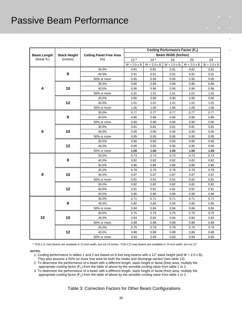
30
Passive Beam Performance
Table 3: Correction Factors for Other Beam Configurations
12 * 14 * 16 20 24
W = 2.0 x B W = 2.0 x B W = 2.0 x B W = 2.0 x B W = 2.0 x B
30.0% 0.81 0.81 0.81 0.81 0.81
40.0% 0.91 0.91 0.91 0.91 0.91
50% or more 0.95 0.95 0.95 0.95 0.95
30.0% 0.86 0.86 0.86 0.86 0.86
40.0% 0.96 0.96 0.96 0.96 0.96
50% or more 1.01 1.01 1.01 1.01 1.01
30.0% 0.90 0.90 0.90 0.90 0.90
40.0% 1.01 1.01 1.01 1.01 1.01
50% or more 1.06 1.06 1.06 1.06 1.06
30.0% 0.77 0.77 0.77 0.77 0.77
40.0% 0.86 0.86 0.86 0.86 0.86
50% or more 0.90 0.90 0.90 0.90 0.90
30.0% 0.81 0.81 0.81 0.81 0.81
40.0% 0.90 0.90 0.90 0.90 0.90
50% or more 0.95 0.95 0.95 0.95 0.95
30.0% 0.85 0.85 0.85 0.85 0.85
40.0% 0.95 0.95 0.95 0.95 0.95
50% or more 1.00 1.00 1.00 1.00 1.00
30.0% 0.73 0.73 0.73 0.73 0.73
40.0% 0.82 0.82 0.82 0.82 0.82
50.0% 0.86 0.86 0.86 0.86 0.86
30.0% 0.78 0.78 0.78 0.78 0.78
40.0% 0.87 0.87 0.87 0.87 0.87
50% or more 0.91 0.91 0.91 0.91 0.91
30.0% 0.82 0.82 0.82 0.82 0.82
40.0% 0.91 0.91 0.91 0.91 0.91
50.0% 0.96 0.96 0.96 0.96 0.96
30.0% 0.71 0.71 0.71 0.71 0.71
40.0% 0.80 0.80 0.80 0.80 0.80
50% or more 0.84 0.84 0.84 0.84 0.84
30.0% 0.75 0.75 0.75 0.75 0.75
40.0% 0.84 0.84 0.84 0.84 0.84
50% or more 0.88 0.88 0.88 0.88 0.88
30.0% 0.79 0.79 0.79 0.79 0.79
40.0% 0.88 0.88 0.88 0.88 0.88
50% or more 0.93 0.93 0.93 0.93 0.93
* TCB-1 (1 row) beams are available in 12 inch width, but not 14 inches. TCB-2 (2 row) beams are available in 14 inch width, but not 12".
Beam Length
(linear ft.)
Stack Height
(inches)
Ceiling Panel Free Area
(%)
Cooling Performance Factor (FC)
Beam Width (Inches)
4
8
10
12
6
8
10
12
8
8
10
12
10
8
10
12
NOTES:
1. Cooling performance in tables 1 and 2 are based on 6 foot long beams with a 12" stack height (and W = 2.0 x B).
They also assume a 50% (or more free area for both the intake and discharge section (see table 13).
2. To determine the performance of a beam with a different length, stack height or facial (free) area, multiply the appropriate cooling factor (FC) from the table of above by the sensible cooling value from table 1 or 2.
3. To determine the performance of a beam with a different length, stack height or facial (free) area, multiply the appropriate cooling factor (FC) from the table of above by the sensible cooling value from table 1 or 2.

31
Passive Beam Selection
The sensible heat removal of the ventilation air can then be calculated as follows: qVENT = 1.09 x CFMVENT x (TRETURN – TSUPPLY) = 1.09 x (0.2 x 720) x (78 – 65) = 2,040 BTUH The required sensible heat removal of the beams is the total sensible heat gain of the space (8,640 BTUH) less that removed by the air supply (2,040 BTUH) or 6,600 BTUH. In order to contain the beam and its required inlet area within a single 2 foot wide ceiling module, it is desired that 12” wide beams be used. Table 1 indicates four 8 foot long beams with chilled water flow rates of 0.75 GPM (and a 20˚F temperature differential between the entering air and chilled water) could remove the re-quired sensible heat. These would be located uniformly within the space. Passive Beams in Perimeter Applications When passive beams are used for perimeter applica-tions, it is not necessary that the inlet area to the beam be as wide as with interior applications. The momentum of the warm air moving up the façade assists in the de-livery to the beam. Figure 27 illustrates such an applica-tion and suggests that the width of the gap between the beam and the façade can be as little as 33 percent of the beam width, but must be maintained throughout the entire entry passage. For such cases, the performance data shown in tables 1 and 2 may be used. In addition, the beam entering air temperature can be assumed to be 6 to 8°F warmer during design operation. EXAMPLE 2: A TCB-2 (recessed type) passive beam is to be used for conditioning a 120 square foot perimeter space served by a UFAD system. The space design conditions are 74˚F/55% RH. The space sensible heat gain is 45 BTUH per square foot, 10 BTUH per square foot of which will be removed by the pretreated air in the UFAD system. The perimeter exposure is 10 feet long. SOLUTION: The beam entering air temperature can be assumed to be 81˚F. A chilled water supply temperature of 59˚F (1˚F above the space dew point) has been chosen, therefore the temperature difference between the enter-ing air and entering water is 22˚F. The passive beam selected must be capable of removing 4,200 BTUH (35 BTUH per square foot) of sensible heat. If an 8 foot long beam is to be used, it must remove 525 BTUH per lin-ear foot. According to table 2, a 20 inch wide beam at 1.5 GPM could be used.
ACTIVE BEAM SELECTION AND LOCATION In addition to sensible heat removal and water side pressure loss effects, active chilled beam selection and location should also consider acoustical and air side pressure effects as well as room air distribution per-formance and its effect on occupant thermal comfort. TROX DID active chilled beams offer a range of air noz-zles that afford the designer to tailor the beam selection to the space cooling and air distribution requirements. DID300 and DID600U series beams offer three different nozzle sizes (A, B or C) . Type A nozzles are the small-est in diameter, create the highest induction ratios and thus provide the greatest sensible cooling per CFM of primary air. Their small diameter however also results in higher air side pressure losses which limit the primary airflow rates through the beam. These beams are com-monly used for interior spaces where ventilation rates are very low compared to the sensible load. Type C nozzles are the largest in diameter and allow considerably higher primary airflow rates. Use of type C nozzles will allow the most sensible cooling per linear foot of beam of all the nozzles. These beams are most often used when reasonably high primary airflow rates are necessary. Type B nozzles are considerably larger than type A but still smaller than type C nozzles. Their performance is thus a compromise between the other two nozzle types. DID620 series beams offer four nozzle sizes (G, M, Z and K), but the most predominantly used are the G and
Blind Box
0.5 x B
B
H
0.3 x B
Figure 27: Passive Beams for Perimeter Cooling Applications

32
Active Beam Selection and Location
M types. The type G nozzle produces induction ratios similar to the type C nozzles previously discussed but with slightly higher pressure drops and noise levels. Type M nozzles produce induction ratios that are some 15% higher, but at an additional pressure drop and noise level. For information on nozzle types Z and K contact TROX USA. Table 4 below presents a brief performance com-parison of the various nozzle types.
Chilled water supply and return temperatures Before an active chilled beam selection can be made, it is necessary that an appropriate chilled water supply temperature be identified. TROX USA recommends that the chilled water supply temperature to active beams be selected and maintained at or above the space dew point temperature in order to assure that condensation does not occur. Return water temperatures will gener-ally be 3 to 6˚F higher than the supply water tempera-ture.
BTUH/LF BTUH/CFM BTUH/LF BTUH/CFM
5.0 0.19 <15 247 49.4 356 71.2
8.0 0.48 23 360 45.0 534 66.8
11.0 0.91 32 433 39.3 672 61.1
8.0 0.18 <13 316 39.5 490 61.3
13.0 0.47 26 419 32.2 702 54.0
18.0 0.91 35 504 28.0 896 49.8
13.0 0.22 18 347 26.7 630 48.5
19.0 0.47 28 432 22.7 846 44.5
25.0 0.81 36 505 20.2 1050 42.0
6.0 0.32 <15 454 75.7 585 97.5
8.0 0.57 20 549 68.6 723 90.4
10.0 0.89 25 634 63.4 852 85.2
10.0 0.29 18 543 54.3 761 76.1
14.0 0.58 27 673 48.1 979 69.9
18.0 0.96 33 787 43.7 1179 65.5
15.0 0.28 22 561 37.4 888 59.2
21.0 0.55 31 695 33.1 1153 54.9
27.0 0.91 38 812 30.1 1400 51.9
6.0 0.32 <15 523 87.1 653 108.9
8.0 0.57 20 638 79.7 812 101.5
10.0 0.89 25 743 74.3 961 96.1
10.0 0.29 18 630 63.0 848 84.8
14.0 0.58 27 793 56.6 1098 78.4
18.0 0.96 33 938 52.1 1330 73.9
15.0 0.28 22 653 43.5 980 65.3
21.0 0.55 31 821 39.1 1278 60.9
27.0 0.91 38 970 35.9 1559 57.7
5.0 0.17 <15 292 58.4 401 80.2
8.0 0.45 17 460 57.5 634 79.3
11.0 0.85 25 566 51.4 806 73.2
10.0 0.19 <15 417 41.7 635 63.5
16.0 0.49 27 592 37.0 941 58.8
22.0 0.92 36 702 31.9 1182 53.7
4.0 0.17 <15 319 79.7 406 101.5
8.0 0.45 17 511 63.9 685 85.7
12.0 0.85 25 636 53.0 898 74.8
10.0 0.19 <15 461 46.1 679 67.9
16.0 0.49 27 667 41.7 1016 63.5
22.0 0.92 36 802 36.4 1281 58.2
NOTES:
C
4.2
3.3
4. Values shown above are based on six (6) foot active beams with two slot (two way) discharge.
DID-302-US
5.3
B 4.2
A
3.2
Maximum Chilled
Water Flow Rate
(GPM)
1.5
3.0
3.0
1.5
Secondary Cooling 2
Total Cooling 3
1. Induction ratio is volumetric measure of total supply airflow rate divided by the ducted (primary) airflow rate.
2. Secondary (sensible) cooling is based on a 18˚F temperature differential between the room and the entering chilled water.
Primary Airflow
CFM/LF
ΔPAIR
inches H2ONC
C
Active Beam
Series
DID-602-HC
Nozzle
Type
Induction
Ratio 1
A 5.3
M 4.8
G 3.7
DID-622-HC
differential between the room and the entering primary air).
3. Total (sensible) cooling is the sum of the secondary cooling (defined in note 2) and the primary air contribution (based on a 20˚F temperature
B
DID-602-US
A 5.3
B 4.2
C 3.3
DID-622-US
M 4.8
1.5
G 3.7
Table 4: Nozzle Types and Performance for TROX (2 Slot) Active Chilled Beams

33
Active Beam Selection and Location
Water flow rate and pressure loss considerations Water flow velocities in excess of 4 feet per second should be avoided in order to prevent unwanted noise. Design water flow rates below 0.25 gallons per minute are not recommended as laminar flow begins to occur below this flow rate and coil performance may be re-duced. Chilled beams should also be selected such that their water side head loss does not exceed 10 feet of water. Air side design considerations Although active chilled beams remove large amounts sensible heat from the room air that is circulated through them, it is very important that the designer does not treat them as purely an air conditioning device. They are also an air distribution device and their proper se-lection and placement is paramount to the maintenance of thermal comfort within the space. The design of ac-tive chilled beam systems must not only consider the sensible cooling (and or heating) capacities of the beams but also their resultant room air distribution. Figure 18 can be used to predict local velocities for ac-tive chilled beams. In order to prevent excessive veloci-ties in the occupied zone, it is recommended that the beam discharge airflow rate (primary plus induced room air) not be greater than 40 CFM per linear foot of slot, therefore 2 slot beams should not be sized for primary airflow rates in excess of 80 CFM per linear foot of beam. The primary airflow rate to active chilled beams must be sufficient to maintain proper ventilation of the space7. The preconditioning of the primary air delivery must also enable the primary air supply to provide adequate space dehumidification without assistance from the cooling coil within the beam. When active beams are applied in humid climates, designing for a space relative humidity level near 55% will often result in a more effec-tive application of the chilled beam system. This is par-ticularly true when the dew point temperature of the primary air cannot be suppressed below about 53˚F (see further discussion see page 13). Oftentimes, the cooling, ventilation and/or demands for areas fed by the same air handling unit vary. In such cases, the designer should attempt to match the inlet pressure requirements of those beams as closely as possible in order to reduce the noise that can be gener-ated by pressure regulating dampers in the ductwork. This can often be accomplished by selecting nozzle types that will match the pressure drop to the beam primary airflow rate.
Active beams used for both heating and cooling Active chilled beams can be used for heating as well as cooling. This is commonly done in climates where over-head heating with all air systems is popular. Heating can be accomplished in either of two ways: Beams can be fitted to a four pipe system (using the four pipe performance data) that enables the beam to access either chilled or hot water according to the space demand. A zone heating coil can be provided in the primary air duct that will add the required zone heating to the pri-mary air prior to its entry into the beam. A two pipe sys-tem (delivering chilled water only) will then be sufficient as the zone chilled water valve will remain closed during periods demanding space heating. The latter practice is often employed as it results in far less piping. With either approach, the discharge air tem-perature should not be more than 15°F above that of the room (per ASHRAE recommendations) if adequate overhead heating performance is to be achieved. This same recommendation is valid for all air heating as well. Selecting active beams to do both heating and cooling of perimeter areas requires a close examination of the resultant room air velocities. Figure 18 introduces two velocities (VL2 and VL6) that aid the designer in select-ing beams for this application. VL2 represents the velocity measured two (2) inches from the outside window at the mid-level of the space. For good heating performance this value should be at least 50 FPM during the heating mode. VL6 represents the velocity six (6) inches form the sur-face, and is used to assess the draft risk during cooling operation. For minimal draft risk, the VL6 value should not exceed about 75 FPM. A good beam selection will conform to both of the rec-ommendations cited. Active beams operated in a VAV mode Although they primarily deliver constant air volume (at a variable temperature) active beams may be operated in a VAV mode when space cooling requirements vary greatly (conference rooms, etc.). In such cases there is little concern over “dumping” at low discharge velocities as the cooling coil is off and the discharge air tempera-ture is only a few degrees below that of the room being served.

34
Active beam performance data Performance data for DID600 series, DID620 series, and DID300 series active chilled beams are presented in figures 30 through 55. Table 5 may be used as a reference to that data. Note that this performance data pertains only to those beams manufactured by TROX USA and is intended for the sole purpose of selecting those products. These data may not be applicable to versions offered by other TROX companies. TROX USA also offers electronic selection pro-grams for all of these chilled beams. Contact TROX USA or your local representative for details. The cooling capacity nomographs are based on beams of six (6) foot length supplied by primary air whose dry bulb temperature is 20˚F cooler than the room being supplies. The chilled water is supplied at a temperature which is 18°F above the room air being induced into the beam. Cooling performance for each nozzle type is presented. The primary airflow range for each nozzle is limited to that which results in primary air side pressure losses below one (1) inch of water and NC levels below 40 (based on 10dB per octave band room attenuation. The minimum cooling capacities shown are with no chilled water contribution and represent the sensible cooling provided by the preconditioned primary air sup-ply.
Use of these nomographs will facilitate the selection of a nozzle type as well as identify the cooling capacities of the beam for various differentials between the room and entering chilled water temperatures. Similar nomographs are provided for heating applica-tions which assume a primary air delivery temperature that is 20˚F below that of the room and a hot water sup-ply that is 50°F warmer than the induced room air. Again the primary air ranges for the various nozzles are limited by the air side pressure loss (less than 1” H2O.) and space NC (40) level. In the case of the heating no-mographs, shaded areas are labeled “Primary Air Cool-ing” represents the cooling effect of the primary air. The net sensible heating values shown reflect this primary air cooling effect. Both the cooling and heating nomographs include cor-rection factors for other beam lengths. Corrections should also be made if the room to primary air tempera-ture differential varies from that assumed by the nomo-graphs. Finally, figure 18 is used to estimate local velocities associated with the chilled beam selection and place-ment. The use of these tables is illustrated in the selection examples that follow.
Active Beam Performance Data
Table 5: Reference to Active Beam Performance Data
DID601(1 Slot)
Active Beam Type and Discharge Configuration
Cooling Performance (2 Pipe Variants)
- Sensible cooling capacities
- Chilled water flow rates
- Airside pressure loss data
- Acoustical (NC) data
Cooling Performance (4 Pipe Variants)
- Sensible cooling capacities
- Chilled water flow rates
- Airside pressure loss data
- Acoustical (NC) data
Heating Performance (2 Pipe Variants)
- Sensible heating capacities
- Hot water flow rates
- Airside pressure loss data
- Acoustical (NC) data
Chilled Water Pressure Loss (2 Pipe Coils)
Chilled Water Pressure Loss (4 Pipe Coils)
Hot Water Pressure Loss (4 Pipe Coils)
Figure 40
Figure 42
Figure 44
Figures 32
and 34
Figures 33
and 35
Figure 36
DID602(2 Slot)
Figure 41
Figure 43
Figure 45
Figures 32
and 34
Figures 33
and 35
Figure 36
DID621(1 Slot)
Figure 46
Figure 48
Figure 50
Figures 32
and 34
Figures 33
and 35
Figure 36
DID622(2 Slot)
Figure 47
Figure 49
Figure 51
Figures 32
and 34
Figures 33
and 35
Figure 36
DID301(1 Slot)
Figure 52
Figure 54
Figure 56
Figure 37
Figure 38
Figure 39
DID302(2 Slot)
Figure 53
Figure 55
Figure 57
Figure 37
Figure 38
Figure 39
Performance Parameter
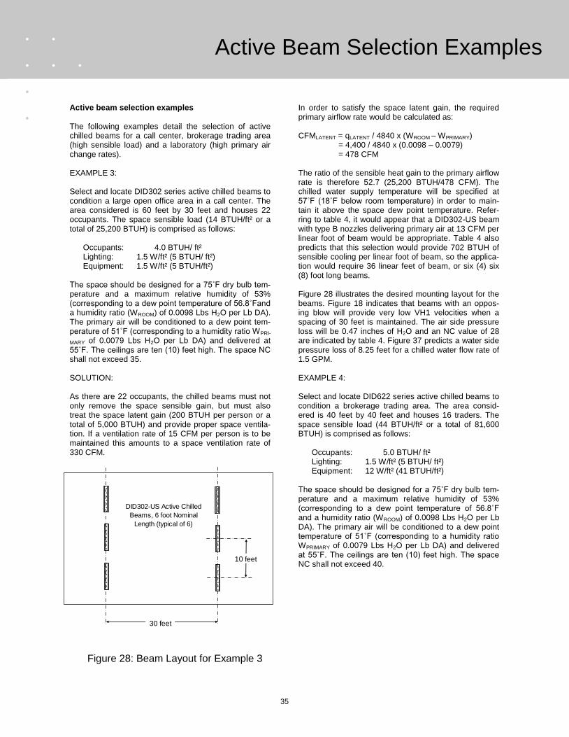
35
Active Beam Selection Examples
Active beam selection examples The following examples detail the selection of active chilled beams for a call center, brokerage trading area (high sensible load) and a laboratory (high primary air change rates). EXAMPLE 3: Select and locate DID302 series active chilled beams to condition a large open office area in a call center. The area considered is 60 feet by 30 feet and houses 22 occupants. The space sensible load (14 BTUH/ft² or a total of 25,200 BTUH) is comprised as follows: Occupants: 4.0 BTUH/ ft² Lighting: 1.5 W/ft² (5 BTUH/ ft²) Equipment: 1.5 W/ft² (5 BTUH/ft²) The space should be designed for a 75˚F dry bulb tem-perature and a maximum relative humidity of 53% (corresponding to a dew point temperature of 56.8˚Fand a humidity ratio (WROOM) of 0.0098 Lbs H2O per Lb DA). The primary air will be conditioned to a dew point tem-perature of 51˚F (corresponding to a humidity ratio WPRI-
MARY of 0.0079 Lbs H2O per Lb DA) and delivered at 55˚F. The ceilings are ten (10) feet high. The space NC shall not exceed 35. SOLUTION: As there are 22 occupants, the chilled beams must not only remove the space sensible gain, but must also treat the space latent gain (200 BTUH per person or a total of 5,000 BTUH) and provide proper space ventila-tion. If a ventilation rate of 15 CFM per person is to be maintained this amounts to a space ventilation rate of 330 CFM.
In order to satisfy the space latent gain, the required primary airflow rate would be calculated as: CFMLATENT = qLATENT / 4840 x (WROOM – WPRIMARY) = 4,400 / 4840 x (0.0098 – 0.0079) = 478 CFM The ratio of the sensible heat gain to the primary airflow rate is therefore 52.7 (25,200 BTUH/478 CFM). The chilled water supply temperature will be specified at 57˚F (18˚F below room temperature) in order to main-tain it above the space dew point temperature. Refer-ring to table 4, it would appear that a DID302-US beam with type B nozzles delivering primary air at 13 CFM per linear foot of beam would be appropriate. Table 4 also predicts that this selection would provide 702 BTUH of sensible cooling per linear foot of beam, so the applica-tion would require 36 linear feet of beam, or six (4) six (8) foot long beams. Figure 28 illustrates the desired mounting layout for the beams. Figure 18 indicates that beams with an oppos-ing blow will provide very low VH1 velocities when a spacing of 30 feet is maintained. The air side pressure loss will be 0.47 inches of H2O and an NC value of 28 are indicated by table 4. Figure 37 predicts a water side pressure loss of 8.25 feet for a chilled water flow rate of 1.5 GPM. EXAMPLE 4: Select and locate DID622 series active chilled beams to condition a brokerage trading area. The area consid-ered is 40 feet by 40 feet and houses 16 traders. The space sensible load (44 BTUH/ft² or a total of 81,600 BTUH) is comprised as follows: Occupants: 5.0 BTUH/ ft² Lighting: 1.5 W/ft² (5 BTUH/ ft²) Equipment: 12 W/ft² (41 BTUH/ft²) The space should be designed for a 75˚F dry bulb tem-perature and a maximum relative humidity of 53% (corresponding to a dew point temperature of 56.8˚F and a humidity ratio (WROOM) of 0.0098 Lbs H2O per Lb DA). The primary air will be conditioned to a dew point temperature of 51˚F (corresponding to a humidity ratio WPRIMARY of 0.0079 Lbs H2O per Lb DA) and delivered at 55˚F. The ceilings are ten (10) feet high. The space NC shall not exceed 40.
30 feet
10 feet
DID302-US Active Chilled
Beams, 6 foot Nominal
Length (typical of 6)
Figure 28: Beam Layout for Example 3

36
SOLUTION: The beams must be selected to remove 70,400 BTUH (44 BTUH/FT²) of sensible heat from the space. The beams‟ primary airflow rate must also be sufficient to handle the latent gain from the 16 occupants (200 BTUH per person or a total of 3,200 BTUH) and provide proper ventilation (176 CFM per ASHRAE Standard 62.1-2004) to the space occupants. In order to satisfy the space latent gain, the required primary airflow rate would be calculated as: CFMLATENT = qLATENT / 4840 x (WROOM – WPRIMARY) = 3,200 / 4840 x (0.0098 – 0.0079) = 348 CFM The ideal ratio of the sensible heat gain to the primary airflow rate would be 202 BTUH/CFM of primary air, but this is not achievable for any of the beam/nozzle ar-rangements listed in table 4. The sensible cooling re-quirement will therefore determine the primary airflow rate. The chilled water supply temperature will be specified at 57˚F (18˚F below room temperature) in order to main-tain it above the space dew point temperature. In order to minimize the number of beams, DID622-HC beams (and two pipe –HC coils) will be considered. Figure 47 summarizes the performance of a six (6) foot beam of this type. If “G” nozzles are to be used, an airflow rate of 23 BTUH/LF can be employed within the acoustical constraints defined. This will result in a beam sensible cooling capacity of about 1,275 BTUH/LF (with its maxi-mum chilled water flow rate of 2.25 GPM). In this case, we would require 64 linear feet of beams. If twelve (12) six foot units were provided, the necessary cooling (1,133 BTUH/LF) could be accomplished with a primary airflow rate of 20 CFM/LF and a chilled water flow rate of 2.25 GPM. This results in a space primary airflow requirement of 1,440 CFM. Alternatively, type “M” nozzles could be employed. Fig-ure 45 indicates that these nozzles (in a six foot beam) can provide up to 900 BTUH/LF of sensible cooling with a chilled water flow rate of 2.25 GPM and a primary airflow rate of 12 CFM/LF and. If these nozzles are cho-sen, we need 78 linear feet of beams. If twelve (12) eight foot units (at their maximum chilled water flow rate of 2.0 GPM) are employed, the cooling requirement could be satisfied at a primary airflow rate of 11.5 CFM /LF, or a total primary airflow rate of 1,104 CFM. In either case the NC level would be within specified levels, while the air side pressure drop would be ap-proximately 1.0 inches H2O.
If, in order to minimize the primary airflow requirement, the latter selection were preferred, the beam layout might be as shown in figure 29 below.
Referring to figure 18, the total discharge airflow rate (CFM/LF of beam) of the selection using “M” nozzles is: CFMSUPPLY = CFMPRIMARY x Induction Ratio = 11.5 CFM/LF x 4.8 = 55 CFM/LF As the beam has 2 slots, this equates to 27.5 CFM per linear foot of slot. The beam spacing (A) is twelve feet so A/2 is six feet. Figure 18 indicates that, the velocities VH1 and VL6 six feet below the ceiling velocity will be approximately 30 and 58 FPM, respectively. These are well within the values recommended. The airside pressure loss is about 0.93 inches H2O and the NC level (27) is well within the range specified. EXAMPLE 5: DID602 series beams are to be used for a biological laboratory module. The laboratory module is 30 by 20 feet (600 ft²) with ten (10) foot ceilings. The space sen-sible cooling load is 70 BTUH/ft² while the total space latent load is 2,000 BTUH. A minimum air change rate of 8 ACH-1 will be required. The velocity at the six foot level of the occupied space should not exceed 60 FPM while that along the wall cannot exceed 100 FPM. The design conditions within the laboratory are 75˚F/50% RH (W = 0.0092 LBM H2O per pound dry air, dew point temperature of 55.2˚F). The NC shall not
Active Beam Selection Examples
Figure 29: Chilled Beam Layout for Selection Example 4
12 feet 12 feet
40 feet

37
Active Beam Selection Examples
exceed 40 nor shall the primary air pressure drop ex-ceed 1.0 inches H2O. The primary air supply is to be delivered at 55˚F with a dew point temperature of 52˚F (W = 0.0082 LBM H2O per pound dry air). The beams are to be located directly above the work benches in order to capture the most sensible heat. Figure 30 illustrates the bench layout for the lab. SOLUTION: As the space dew point temperature is 55.2˚F, a 56˚F chilled water supply temperature will be used. As the beams are to be located directly above the benches where most of the space heat sources reside, the in-duced air entering the beams will be assumed to be 2°F warmer than the room air resulting in a 21˚F tempera-ture differential between the room air and the entering chilled water. The minimum primary air delivery to the space for venti-lation purposes is 8 ACH-1, or 800 CFM. The amount of primary air required to satisfy the space latent load may be calculated as: CFMLATENT = qLATENT / 4840 x (WROOM – WPRIMARY) = 2,000 / 4840 x (0.0092 – 0.0082) = 413 CFM As this is less than the ventilation requirement, the mini-mum primary airflow delivery will be 800 CFM. The total space sensible load is 42,000 BTUH. Ideally, the beam selected should provide 52.5 (42,000 / 800) BTUH of sensible cooling per CFM of primary air. Table 4 indicates that DID602 beams with “C” nozzles can provide such a ratio. The layout of the laboratory would favor the placement of one or two beams over each bench, so we will con-sider the use of four (8) eight foot beams. Applying the correction factors from figure 41 we see that an eight foot beam can provide 25 CFM/LF of primary air while keeping the air side pressure drop of inches H2O. The NC level (39) would also be acceptable. In order to sup-ply the required air changes (800 CFM), we would need 32 feet of these beams or four (4) eight foot lengths. As figure 41 is based on an 18°F temperature difference between the air and chilled water entering the beam, we must correct the water side sensible cooling according to the correction factor (1.16) shown in table 6 (page 38) while the primary air contribution (567 BTUH/LF or 17,400 BTUH total) remains the same. The sensible cooling provided the chilled water coil must thus be 24,600 BTUH or 769 BTUH/LF. Applying the correction factor (1.16) from table 6, we enter figure 41 to deter-mine the chilled water flow rate that will provide 663 (769/1.16) BTUH/LF of water side sensible cooling or 1,230 (663 + 567) BTUH/LF of total sensible cooling.
This relates to a chilled water flow rate of 1.0 GPM. Figure 31 illustrates the proposed beam placement. Referring to figure 18, the total air supply from each beam will be 666 CFM or 40 CFM per linear foot of slot. As A/2 is 8 feet and X is 7 feet, the value of VH1 and VL6 at the six foot (H - H1 = 4 feet) level will be 56 and 86 FPM, respectively. The water side pressure drop for DID602-US and DID602-HC can be found in figures 32 and 34, respec-tively.
8 feet
(typical)
Lab
Benches
16 feet
(typical)
DID602-US Active
Chilled Beam
(8 ft. Long, "C" Nozzles)
(typical of 4)
Figure 31: Chilled Beam Arrangement for Example 5
Figure 30: Lab Bench Arrangement for Example 5

38
Nomenclature and Performance Notes
VH1: Local velocity at the top of the occupied zone directly below the point of collision of opposing air streams
TH1: Local temperature at the top of the occupied zone directly below the point of collision of opposing air streams
TL2: Local temperature at the top of the occupied zone measured two (2) inches from an outside wall
VL2: Local velocity at the top of the occupied zone measured two (2) inches from an outside wall
VL6: Local velocity at the top of the occupied zone measured six (6) inches from an outside wall
TL6: Local temperature at the top of the occupied zone measured six (6) inches from an outside wall
A: Centerline distance between two active beams with opposing blows
X: Distance between active beam centerline and an adjacent wall
H: Mounting height of active chilled beam
H1: Height of occupied zone (usually considered 42” for seated occupants, 66 inches for standing occupants)
TINDUCED AIR: Dry bulb temperature of room air entering the chilled beam cooling coil
TCWS: Temperature of the chilled water entering the chilled beam transfer coil (cooling mode)
THWS: Temperature of the hot water entering the chilled beam heat transfer coil (heating mode)
Induction ratio: Ratio of discharge airflow rate (to the room) to primary (ducted) airflow rate
Net sensible heating: Beam water side heating less the cooling effect of the (cooler) primary air
Occupied Zone Height (H1)
6" for Cooling
2" for Heating
3.3 ft.
1 ft.OCCUPIED ZONE
(as defined by ASHRAE Std. 55-2004)
VH1
ΔTH1
H - H1
H
Beam Spacing (A)
A/2X
L (X + H1)
VL
ΔTL
ΔTZ
TSUPPLY
tINDUCED AIR - tCWS
Water Side Sensible
Cooling Correction
Factor
12°F
0.67
14°F
0.78
16°F
0.89
18°F
1.0
20°F
1.11
22°F
1.22
tIHWS - tINDUCED AIR
Water Side Heating
Correction Factor
20°F
0.4
30°F
0.6
40°F
0.8
50°F
1.0
60°F
1.2
70°F
1.4
Nomenclature
Table 6: Water Side Correction Factors for Various Entering Air to Entering Chilled Water
Temperature Differentials
Table 7: Water Side Correction Factors for Various Entering Air to Entering Hot Water
Temperature Differentials

39
Water Side Pressure Loss
Water Flow Rate (GPM)
9.0
8.0
7.0
6.0
5.0
4.0
3.0
2.0
Ch
ille
d W
ate
r P
ressu
re D
rop
(F
T H
2O
)
0.25 0.50 0.75 1.00 1.25 1.50
1.0
Se
lectio
n fo
r D
esig
n W
ate
r F
low
Ra
tes L
ess th
an
0.2
5 G
PM
is N
ot R
eco
mm
en
de
d
6 Foot Nominal Length
Max. GPM = 1.35
4 Foot Nominal Length
Max. GPM = 1.5
10 Foot Nominal Length
Max. GPM = 1.1
8 Foot Nominal Length
Max. GPM = 1.2
Figure 33: 4 Pipe Standard Capacity Coil Chilled Water Pressure Loss Models DID601-US-4, DID602-US-4, DID621-US-4 and DID622-US-4
Figure 32: 2 Pipe Standard Capacity Coil Chilled Water Pressure Loss Models DID601-US-2, DID602-US-2, DID621-US-2 and DID622-US-2
Water Flow Rate (GPM)
9.0
8.0
7.0
6.0
5.0
4.0
3.0
2.0
Ch
ille
d W
ate
r P
ressu
re D
rop
(F
T H
2O
)
0.25 0.50 0.75 1.00 1.25 1.50
1.0
Se
lectio
n fo
r D
esig
n W
ate
r F
low
Ra
tes L
ess th
an
0.2
5 G
PM
is N
ot R
eco
mm
en
de
d
6 Foot Nominal Length
Max. GPM = 1.15
4 Foot Nominal Length
Max. GPM = 1.35
10 Foot Nominal Length
Max. GPM = 0.90
8 Foot Nominal Length
Max. GPM = 1.0
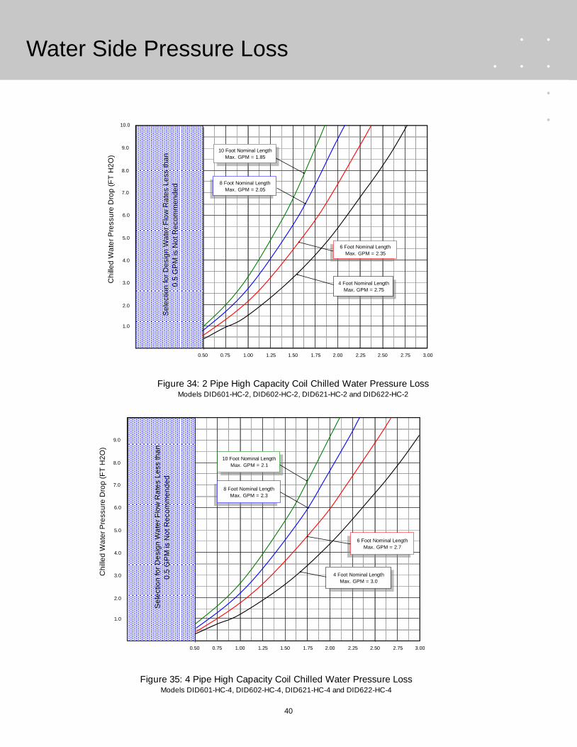
40
Water Side Pressure Loss
Figure 34: 2 Pipe High Capacity Coil Chilled Water Pressure Loss Models DID601-HC-2, DID602-HC-2, DID621-HC-2 and DID622-HC-2
10.0
9.0
8.0
7.0
6.0
5.0
4.0
3.0
2.0
Ch
ille
d W
ate
r P
ressu
re D
rop
(F
T H
2O
)
0.50 0.75 1.00 1.25 1.50 1.75 2.00 2.25 2.50 2.75 3.00
1.0
Se
lectio
n fo
r D
esig
n W
ate
r F
low
Ra
tes L
ess th
an
0.5
GP
M is N
ot R
eco
mm
en
de
d
6 Foot Nominal Length
Max. GPM = 2.35
4 Foot Nominal Length
Max. GPM = 2.75
10 Foot Nominal Length
Max. GPM = 1.85
8 Foot Nominal Length
Max. GPM = 2.05
9.0
8.0
7.0
6.0
5.0
4.0
3.0
2.0
Ch
ille
d W
ate
r P
ressu
re D
rop
(F
T H
2O
)
0.50 0.75 1.00 1.25 1.50 1.75 2.00 2.25 2.50 2.75 3.00
1.0
Se
lectio
n fo
r D
esig
n W
ate
r F
low
Ra
tes L
ess th
an
0.5
GP
M is N
ot R
eco
mm
en
de
d
6 Foot Nominal Length
Max. GPM = 2.7
4 Foot Nominal Length
Max. GPM = 3.0
10 Foot Nominal Length
Max. GPM = 2.1
8 Foot Nominal Length
Max. GPM = 2.3
Figure 35: 4 Pipe High Capacity Coil Chilled Water Pressure Loss Models DID601-HC-4, DID602-HC-4, DID621-HC-4 and DID622-HC-4

41
Water Side Pressure Loss
4.5
4.0
3.5
3.0
2.5
2.0
1.5
1.0
Ho
t W
ate
r P
ressu
re D
rop
(F
T H
2O
)
0.25 0.50 0.75 1.00 1.25 1.50
0.5
Figure 36: 4 Pipe (Std. or High Capacity) Hot Water Coils Pressure Loss Models DID601-US-4, DID602-US-4, DID621-US-4 and DID622-US-4,
DID601-HC-4, DID602-HC-4, DID621-HC-4 and DID622-HC-4
Se
lectio
n fo
r D
esig
n W
ate
r F
low
Ra
tes L
ess th
an
0.2
5 G
PM
is N
ot R
eco
mm
en
de
d
5.0
5.5
10 Foot Nominal Length
4 Foot Nominal Length
6 Foot Nominal Length
8 Foot Nominal Length
6.0
Water Flow Rate (GPM)

42
Water Side Pressure Loss
Figure 37: 2 Pipe Standard Capacity Coil Chilled Water Pressure Loss Models DID301-US-2 and DID302-US-2
9.0
8.0
7.0
6.0
5.0
4.0
3.0
2.0
Ch
ille
d W
ate
r P
ressu
re D
rop
(F
T H
2O
)
0.25 0.50 0.75 1.00 1.25 1.50
1.0
Se
lectio
n fo
r D
esig
n W
ate
r F
low
Ra
tes L
ess th
an
0.2
5 G
PM
is N
ot R
eco
mm
en
de
d
10 Foot Nominal Length
Max. GPM = 1.3
8 Foot Nominal Length
Max. GPM = 1.45
6 Foot Nominal Length
Max. GPM = 1.5
4 Foot Nominal Length
Max. GPM = 1.5
Figure 38: 4 Pipe Standard Capacity Coil Chilled Water Pressure Loss Models DID301-US-4 and DID302-US-4
9.0
8.0
7.0
6.0
5.0
4.0
3.0
2.0
Ch
ille
d W
ate
r P
ressu
re D
rop
(F
T H
2O
)
0.25 0.50 0.75 1.00 1.25 1.50
1.0
Se
lectio
n fo
r D
esig
n W
ate
r F
low
Ra
tes L
ess th
an
0.2
5 G
PM
is N
ot R
eco
mm
en
de
d
Water Flow Rate (GPM)
10 Foot Nominal Length
Max. GPM = 1.5
8 Foot Nominal Length
Max. GPM = 1.5
6 Foot Nominal Length
Max. GPM = 1.35
4 Foot Nominal Length
Max. GPM = 1.5
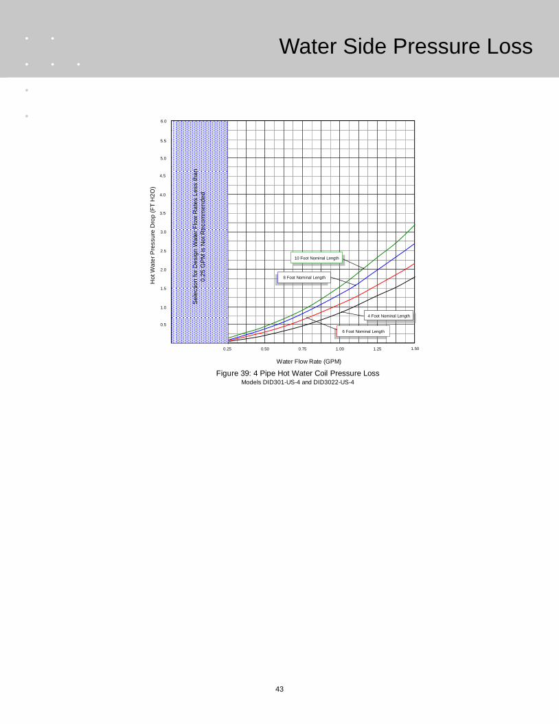
43
Water Side Pressure Loss
1.50
Figure 39: 4 Pipe Hot Water Coil Pressure Loss Models DID301-US-4 and DID3022-US-4
4.5
4.0
3.5
3.0
2.5
2.0
1.5
1.0
Ho
t W
ate
r P
ressu
re D
rop
(F
T H
2O
)
0.25 0.50 0.75 1.00 1.25
0.5
Se
lectio
n fo
r D
esig
n W
ate
r F
low
Ra
tes L
ess th
an
0.2
5 G
PM
is N
ot R
eco
mm
en
de
d
5.0
5.5
6.0
Water Flow Rate (GPM)
10 Foot Nominal Length
4 Foot Nominal Length
6 Foot Nominal Length
8 Foot Nominal Length
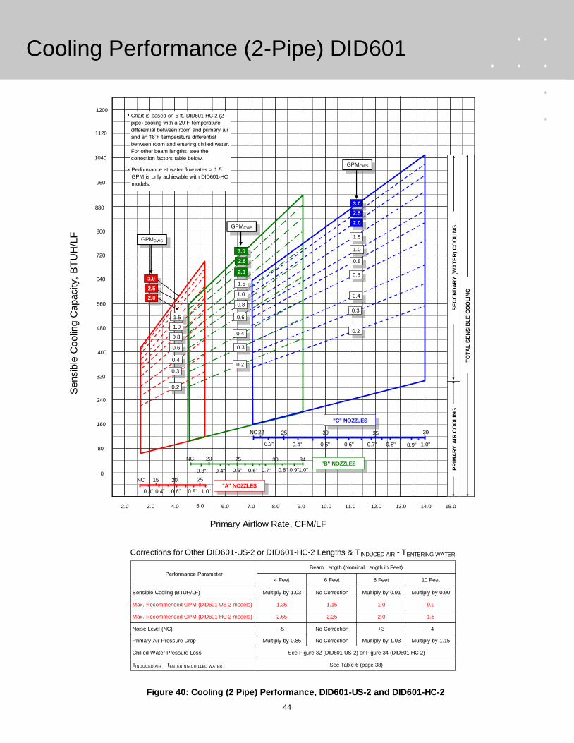
44
Cooling Performance (2-Pipe) DID601
Figure 40: Cooling (2 Pipe) Performance, DID601-US-2 and DID601-HC-2
Performance Parameter4 Feet 8 Feet6 Feet 10 Feet
Beam Length (Nominal Length in Feet)
Multiply by 1.03 Multiply by 0.91No Correction Multiply by 0.90
-5 +3No Correction +4
Multiply by 0.85 Multiply by 1.03No Correction Multiply by 1.15
Sensible Cooling (BTUH/LF)
Noise Level (NC)
Primary Air Pressure Drop
Chilled Water Pressure Loss See Figure 32 (DID601-US-2) or Figure 34 (DID601-HC-2)
TINDUCED AIR - TENTERING CHILLED WATER
Corrections for Other DID601-US-2 or DID601-HC-2 Lengths & T INDUCED AIR - TENTERING WATER
Sensib
le C
oolin
g C
apacity,
BT
UH
/LF
880
720
640
560
480
400
320
800
960
240
160
Primary Airflow Rate, CFM/LF
3.0 4.0 9.0 14.06.05.0 11.010.07.0 8.0 12.0 13.0
80
2.0
0
1040
1120
See Table 6 (page 38)
1.35 1.01.15 0.9Max. Recommended GPM (DID601-US-2 models)
2.65 2.02.25 1.8Max. Recommended GPM (DID601-HC-2 models)
1200
15.0
Chart is based on 6 ft. DID601-HC-2 (2
pipe) cooling with a 20˚F temperature
differential between room and primary air
and an 18˚F temperature differential
between room and entering chilled water.
For other beam lengths, see the
correction factors table below.
Performance at water flow rates > 1.5
GPM is only achievable with DID601-HC
models.
0.3" 0.4" 0.6" 0.8" 1.0"
15 20 25NC"A" NOZZLES
NC
0.3"
20
0.4"
25
0.5" 0.6"
30
0.7" 0.8" 0.9"1.0"
34"B" NOZZLES
0.6" 0.7" 0.8" 0.9" 1.0"0.3" 0.4" 0.5"
25 30 35 3922NC
"C" NOZZLES
PR
IMA
RY
AIR
CO
OL
ING
SE
CO
ND
AR
Y (
WA
TE
R)
CO
OL
ING
TO
TA
L S
EN
SIB
LE
CO
OL
ING
GPMCWS
0.6
0.8
0.3
0.2
0.4
2.5
2.0
1.5
1.0
0.8
0.6
0.3
0.2
0.3
0.4
0.6
3.0
2.5
2.0
1.5
1.0
GPMCWS
GPMCWS
0.80.4
0.2
1.0
1.5
2.5
2.0
3.0
3.0
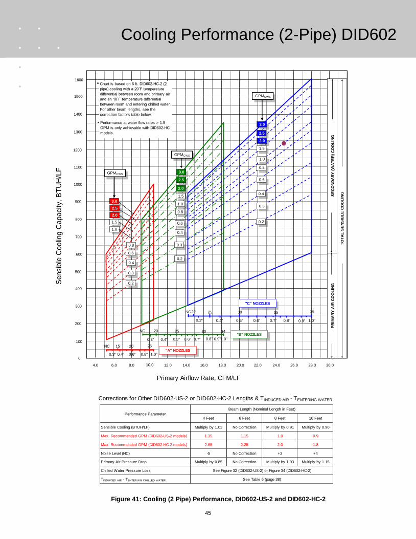
45
Cooling Performance (2-Pipe) DID602
Figure 41: Cooling (2 Pipe) Performance, DID602-US-2 and DID602-HC-2
Performance Parameter4 Feet 8 Feet6 Feet 10 Feet
Beam Length (Nominal Length in Feet)
Multiply by 1.03 Multiply by 0.91No Correction Multiply by 0.90
-5 +3No Correction +4
Multiply by 0.85 Multiply by 1.03No Correction Multiply by 1.15
Sensible Cooling (BTUH/LF)
Noise Level (NC)
Primary Air Pressure Drop
Chilled Water Pressure Loss See Figure 32 (DID602-US-2) or Figure 34 (DID602-HC-2)
TINDUCED AIR - TENTERING CHILLED WATER
Corrections for Other DID602-US-2 or DID602-HC-2 Lengths & T INDUCED AIR - TENTERING WATER
Sensib
le C
oolin
g C
apacity,
BT
UH
/LF
1200
1000
900
800
700
600
500
1100
1300
400
300
Primary Airflow Rate, CFM/LF
6.0 8.0 18.0 28.012.010.0 22.020.014.0 16.0 24.0 26.0
200
4.0
100
1400
1500
See Table 6 (page 38)
1.35 1.01.15 0.9Max. Recommended GPM (DID602-US-2 models)
2.65 2.02.25 1.8Max. Recommended GPM (DID602-HC-2 models)
1600
0
30.0
Chart is based on 6 ft. DID602-HC-2 (2
pipe) cooling with a 20˚F temperature
differential between room and primary air
and an 18˚F temperature differential
between room and entering chilled water.
For other beam lengths, see the
correction factors table below.
Performance at water flow rates > 1.5
GPM is only achievable with DID602-HC
models.
0.3" 0.4" 0.6" 0.8" 1.0"
15 20 25NC"A" NOZZLES
NC
0.3"
20
0.4"
25
0.5" 0.6"
30
0.7" 0.8" 0.9"1.0"
34"B" NOZZLES
0.6" 0.7" 0.8" 0.9" 1.0"0.3" 0.4" 0.5"
25 30 35 3922NC
"C" NOZZLES
PR
IMA
RY
AIR
CO
OL
ING
SE
CO
ND
AR
Y (
WA
TE
R)
CO
OL
ING
TO
TA
L S
EN
SIB
LE
CO
OL
ING
GPMCWS
1.5
2.0
2.5
0.6
0.8
0.3
0.2
0.4
2.5
2.0
1.5
1.0
0.8
0.6
0.4
0.2
0.3
0.2
0.3
0.4
0.6
0.8
3.0
2.5
2.0
1.5
1.0
GPMCWS
GPMCWS3.0
3.0
1.0

46
Cooling Performance (4-Pipe) DID601
Figure 42: Cooling (4 Pipe) Performance, DID601-US-4 and DID601-HC-4
Performance Parameter4 Feet 8 Feet6 Feet 10 Feet
Beam Length (Nominal Length in Feet)
Multiply by 1.03 Multiply by 0.91No Correction Multiply by 0.90
-5 +3No Correction +4
Multiply by 0.85 Multiply by 1.03No Correction Multiply by 1.15
Sensible Cooling (BTUH/LF)
Noise Level (NC)
Primary Air Pressure Drop
Chilled Water Pressure Loss See Figure 33 (DID601-US-4) or Figure 35 (DID601-HC-4)
TINDUCED AIR - TENTERING CHILLED WATER
Corrections for Other DID601-US-4 or DID601-HC-4 Lengths & T INDUCED AIR - TENTERING WATER
Sensib
le C
oolin
g C
apacity,
BT
UH
/LF
880
720
640
560
480
400
320
800
960
240
160
Primary Airflow Rate, CFM/LF
3.0 4.0 9.0 14.06.05.0 11.010.07.0 8.0 12.0 13.0
80
2.0
0
1040
1120
See Table 6 (page 38)
1.5 1.21.35 1.1Max. Recommended GPM (DID601-US-4 models)
3.0 2.352.65 2.1Max. Recommended GPM (DID601-HC-4 models)
1200
15.0
Chart is based on 6 ft. DID601-HC-4 (4
pipe) cooling with a 20˚F temperature
differential between room and primary air
and an 18˚F temperature differential
between room and entering chilled water.
For other beam lengths, see the
correction factors table below.
Performance at water flow rates > 1.5
GPM is only achievable with DID601-HC
models.
0.3" 0.4" 0.6" 0.8" 1.0"
15 20 25NC"A" NOZZLES
NC
0.3"
20
0.4"
25
0.5" 0.6"
30
0.7" 0.8" 0.9"1.0"
34"B" NOZZLES
0.6" 0.7" 0.8" 0.9" 1.0"0.3" 0.4" 0.5"
25 30 35 3922NC
"C" NOZZLES
PR
IMA
RY
AIR
CO
OL
ING
SE
CO
ND
AR
Y (
WA
TE
R)
CO
OL
ING
TO
TA
L S
EN
SIB
LE
CO
OL
ING
GPMCWS
3.0
0.3
0.4
3.0
2.5
2.0
0.3
0.2
0.3
0.4
3.0
2.5
2.0
1.5
GPMCWS
GPMCWS
0.8
0.4
0.2
1.0
1.5
2.5
2.0
0.8
1.5
1.0
0.61.0
0.6
0.8
0.6
0.2
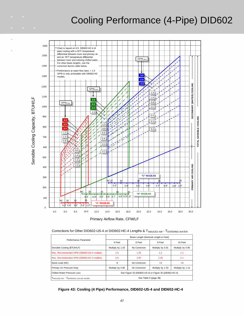
47
Cooling Performance (4-Pipe) DID602
Figure 43: Cooling (4 Pipe) Performance, DID602-US-4 and DID602-HC-4
Sensib
le C
oolin
g C
apacity,
BT
UH
/LF
1200
1000
900
800
700
600
500
1100
1300
400
300
Primary Airflow Rate, CFM/LF
6.0 8.0 18.0 28.012.010.0 22.020.014.0 16.0 24.0 26.0
200
4.0
100
1400
1500
Performance Parameter4 Feet 8 Feet6 Feet 10 Feet
Beam Length (Nominal Length in Feet)
Multiply by 1.03 Multiply by 0.91No Correction Multiply by 0.90
-5 +3No Correction +4
Multiply by 0.85 Multiply by 1.03No Correction Multiply by 1.15
Sensible Cooling (BTUH/LF)
Noise Level (NC)
Primary Air Pressure Drop
Chilled Water Pressure Loss See Figure 33 (DID602-US-4) or Figure 35 (DID602-HC-4)
TINDUCED AIR - TENTERING CHILLED WATER
Corrections for Other DID602-US-4 or DID602-HC-4 Lengths & T INDUCED AIR - TENTERING WATER
See Table 6 (page 38)
1.5 1.21.35 1.1Max. Recommended GPM (DID602-US-4 models)
3.0 2.352.65 2.1Max. Recommended GPM (DID602-HC-4 models)
1600
0
30.0
Chart is based on 6 ft. DID602-HC-4 (4
pipe) cooling with a 20˚F temperature
differential between room and primary air
and an 18˚F temperature differential
between room and entering chilled water.
For other beam lengths, see the
correction factors table below.
Performance at water flow rates > 1.5
GPM is only achievable with DID602-HC
models.
0.3" 0.4" 0.6" 0.8" 1.0"
15 20 25NC"A" NOZZLES
NC
0.3"
20
0.4"
25
0.5" 0.6"
30
0.7" 0.8" 0.9"1.0"
34"B" NOZZLES
0.6" 0.7" 0.8" 0.9" 1.0"0.3" 0.4" 0.5"
25 30 35 3922NC
"C" NOZZLES
PR
IMA
RY
AIR
CO
OL
ING
SE
CO
ND
AR
Y (
WA
TE
R)
CO
OL
ING
TO
TA
L S
EN
SIB
LE
CO
OL
ING
GPMCWS
1.5
2.0
3.0
2.5
0.6
0.8
0.3
0.2
0.4
3.0
2.5
2.0
1.5
1.0
0.8
0.6
0.4
0.2
0.3
0.2
0.3
0.4
0.6
3.0
2.5
2.0
1.5
1.0
GPMCWS
GPMCWS
0.8
1.0

48
Heating Performance (4-Pipe) DID601
Primary Airflow Rate, CFM/LF
600
400
300
200
100
0
-100
500
700
-200
-300
3.0 4.0 9.0 14.06.05.0 11.010.07.0 8.0 12.0 13.0
-400
2.0
-500
800
900
1000
1100
1200
15.0
Chart is based on 6 ft. DID601-HC-4 (4 pipe) heating
with a 20˚F temperature differential between room and
primary air and a 50˚F temperature differential
between room and entering hot water. For other beam
lengths, see the correction factors table below.
Performance Parameter4 Feet 8 Feet6 Feet 10 Feet
Beam Length (Nominal Length in Feet)
Multiply by 1.04 Multiply by 0.88No Correction Multiply by 0.85
-5 +3No Correction +4
Multiply by 0.85 Multiply by 1.03No Correction Multiply by 1.15
Water Side Heating (BTUH/LF)
Noise Level (NC)
Primary Air Pressure Drop
Hot Water Pressure Loss See Figure 36
TENTERING HOT WATER - TINDUCED AIR
Corrections for Other DID601-US-4 or DID601-HC-4 Lengths & TENTERING WATER - TINDUCED AIR
See Table 7 (page 38)
1.5 1.51.5 1.5Max. Recommended GPM (DID601-US-4 models)
1.5 1.51.5 1.5Max. Recommended GPM (DID601-HC-4 models)
Figure 44: Heating (4 Pipe) Performance, DID601-US-4 and DID601-HC-4
0.6" 0.7" 0.8" 0.9" 1.0"0.3" 0.4" 0.5"
25 30 35 3922NC"C" NOZZLES
NC
0.3"
20
0.4"
25
0.5" 0.6"
30
0.7" 0.8" 0.9"1.0"
34
0.3" 0.4" 0.6" 0.8" 1.0"
15 20 25NC
"A" NOZZLES
"B" NOZZLES
PR
IMA
RY
AIR
CO
OL
ING
WA
TE
R S
IDE
HE
AT
ING
NE
T S
EN
SIB
LE
HE
AT
ING
GPMHWS
GPMHWS
GPMHWS
0.6
0.4
0.3
0.2 0.2
0.3
0.4
0.6
1.0
0.8
0.6
0.4
0.3
0.2
1.5
1.5
1.0
0.8
1.5
1.0
0.8
Net
Sensib
le H
eating C
apacity,
BT
UH
/LF
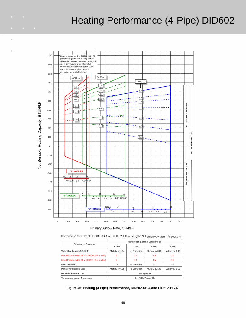
49
Heating Performance (4-Pipe) DID602
Primary Airflow Rate, CFM/LF
400
200
100
0
-100
-200
-300
300
500
-400
-500
6.0 8.0 18.0 28.012.010.0 22.020.014.0 16.0 24.0 26.0
-600
4.0
-700
600
700
800
900
1000
30.0
Chart is based on 6 ft. DID602-HC-4 (4
pipe) heating with a 20˚F temperature
differential between room and primary air
and a 50˚F temperature differential
between room and entering hot water.
For other beam lengths, see the
correction factors table below.
Performance Parameter4 Feet 8 Feet6 Feet 10 Feet
Beam Length (Nominal Length in Feet)
Multiply by 1.04 Multiply by 0.88No Correction Multiply by 0.85
-5 +3No Correction +4
Multiply by 0.85 Multiply by 1.03No Correction Multiply by 1.15
Water Side Heating (BTUH/LF)
Noise Level (NC)
Primary Air Pressure Drop
Hot Water Pressure Loss See Figure 36
TENTERING HOT WATER - TINDUCED AIR
Corrections for Other DID602-US-4 or DID602-HC-4 Lengths & TENTERING WATER - TINDUCED AIR
See Table 7 (page 38)
1.5 1.51.5 1.5Max. Recommended GPM (DID602-US-4 models)
1.5 1.51.5 1.5Max. Recommended GPM (DID602-HC-4 models)
Figure 45: Heating (4 Pipe) Performance, DID602-US-4 and DID602-HC-4
0.6" 0.7" 0.8" 0.9" 1.0"0.3" 0.4" 0.5"
25 30 35 3922NC"C" NOZZLES
NC
0.3"
20
0.4"
25
0.5" 0.6"
30
0.7" 0.8" 0.9"1.0"
34
0.3" 0.4" 0.6" 0.8" 1.0"
15 20 25NC
"A" NOZZLES
"B" NOZZLES
PR
IMA
RY
AIR
CO
OL
ING
WA
TE
R S
IDE
HE
AT
ING
NE
T S
EN
SIB
LE
HE
AT
ING
1.51.5
GPMHWSGPMHWS
GPMHWS
1.51.0
0.8
0.6
0.4
0.3
0.2
0.2
0.3
0.4
0.6
0.8
1.0
1.0
0.8
0.6
0.4
0.3
0.2
Net
Sensib
le H
eating C
apacity,
BT
UH
/LF

50
Figure 46: Cooling (2 Pipe) Performance, DID621-US-2 and DID621-HC-2
Corrections for Other DID621-US-2 or DID621-HC-2 Lengths & T INDUCED AIR - TENTERING WATER
Sensib
le C
oolin
g C
apacity,
BT
UH
/LF
880
720
640
560
480
400
320
800
960
240
160
Primary Airflow Rate, CFM/LF
2.0 3.0 8.0 13.05.04.0 10.09.06.0 7.0 11.0 12.0
80
1.0
0P
RIM
AR
Y A
IR C
OO
LIN
G
0.2" 0.3" 0.4" 0.6" 0.8" 1.0"
15 20 25 27NC
NC
0.3" 0.4" 0.5" 0.6" 0.7" 0.8" 0.9"
25 30 35 3720
1.0"0.2"
1040
1120
SE
CO
ND
AR
Y (
WA
TE
R)
CO
OL
ING
TO
TA
L S
EN
SIB
LE
CO
OL
ING
Chart is based on 6 ft. DID621-HC-2 (2
pipe) cooling with a 20˚F temperature
differential between room and primary air
and an 18˚F temperature differential
between room and entering chilled water.
For other beam lengths, see the
correction factors table below.
Performance at water flow rates > 1.5
GPM is only achievable with DID621-HC
models.
2.0
1.5
1.0
0.6
GPMCWS
2.5
15
0.4
3.0
2.0
3.0
"G" NOZZLES
"M" NOZZLES
0.3
0.2
1.5
0.6
1.0
0.4
0.3
0.2
GPMCWS
Performance Parameter4 feet 8 feet6 feet 10 feet
Beam Length (Nominal Length in Feet)
Multiply by 1.02 Multiply by 0.98No Correction Multiply by 0.90
-5 +3No Correction +6
Multiply by 1.03 Multiply by .98No Correction Multiply by .97
Sensible Cooling (BTUH/LF)
Noise Level (NC)
Primary Air Pressure Drop
Chilled Water Pressure Loss See Figure 32 (DID621-US-2) or 34 (DID621-HC-2)
TINDUCED AIR - TENTERING WATER See Table 6 (page38)
1.35 1.01.15 0.9Max. Recommended GPM (DID621-US-2 models)
2.65 2.02.25 1.8Max. Recommended GPM (DID621-HC-2 models)
Cooling Performance (2-Pipe) DID621

51
Figure 47: Cooling (2 Pipe) Performance, DID622-US-2 and DID622-HC-2
Corrections for Other DID622-US-2 or DID622-HC-2 Lengths & T INDUCED AIR - TENTERING
WATER
Sensib
le C
oolin
g C
apacity,
BT
UH
/LF
1200
1000
900
800
700
600
500
1100
1300
400
300
Primary Airflow Rate, CFM/LF
4.0 6.0 16.0 26.010.08.0 20.018.012.0 14.0 22.0 24.0
200
2.0
100
PR
IMA
RY
AIR
CO
OL
ING
0.2" 0.3" 0.4" 0.6" 0.8" 1.0"
15 20 25 27NC
NC
0.3" 0.4" 0.5" 0.6" 0.7" 0.8" 0.9"
25 30 35 3720
1.0"0.2"
1400
1500
GPMCWS
SE
CO
ND
AR
Y (
WA
TE
R)
CO
OL
ING
TO
TA
L S
EN
SIB
LE
CO
OL
ING
Chart is based on 6 ft. DID622-HC-2 (2
pipe) cooling with a 20˚F temperature
differential between room and primary air
and an 18˚F temperature differential
between room and entering chilled water.
For other beam lengths, see the
correction factors table below.
Performance at water flow rates > 1.5
GPM is only achievable with DID622-HC
models.
2.0
1.5
1.0
GPMCWS
0.3
0.2
0.6
0.4
2.5
15
0.6
0.4
3.0
2.0
1.5
3.0
"G" NOZZLES
"M" NOZZLES
1.0
0.2
0.3
Performance Parameter4 feet 8 feet6 feet 10 feet
Beam Length (Nominal Length in Feet)
Multiply by 1.02 Multiply by 0.98No Correction Multiply by 0.90
-5 +3No Correction +6
Multiply by 1.02 Multiply by .98No Correction Multiply by .97
Sensible Cooling (BTUH/LF)
Noise Level (NC)
Primary Air Pressure Drop
Chilled Water Pressure Loss See Figure 32 (DID622-US-2) or Figure 34 (DID622-HC-2)
TINDUCED AIR - TENTERING CHILLED WATER See table 6 (page38)
1.35 1.01.15 0.9Max. Recommended GPM (DID622-US-2 models)
2.65 2.02.25 1.8Max. Recommended GPM (DID622-HC-2models)
Cooling Performance (2-Pipe) DID622

52
Figure 48: Cooling (4 Pipe) Performance, DID621-US-4 and DID621-HC-4
Corrections for Other DID621-US-4 or DID621-HC-4 Lengths & T INDUCED AIR - TENTERING
WATER
Sensib
le C
oolin
g C
apacity,
BT
UH
/LF
880
720
640
560
480
400
320
800
960
240
160
Primary Airflow Rate, CFM/LF
2.0 3.0 8.0 13.05.04.0 10.09.06.0 7.0 11.0 12.0
80
1.0
0
PR
IMA
RY
AIR
CO
OL
ING
0.2" 0.3" 0.4" 0.6" 0.8" 1.0"
15 20 25 27NC
NC
0.3" 0.4" 0.5" 0.6" 0.7" 0.8" 0.9"
25 30 35 3720
1.0"0.2"
1040
1120
SE
CO
ND
AR
Y (
WA
TE
R)
CO
OL
ING
TO
TA
L S
EN
SIB
LE
CO
OL
ING
Chart is based on 6 ft. DID621-HC-4 (4
pipe) cooling with a 20˚F temperature
differential between room and primary air
and an 18˚F temperature differential
between room and entering chilled water.
For other beam lengths, see the
correction factors table below.
Performance at water flow rates > 1.5
GPM is only achievable with DID621-HC
models.
2.0
1.5
1.0
0.6
GPMCWS
2.5
15
0.4
3.0
2.0
3.0
"G" NOZZLES
"M" NOZZLES
0.3
0.2
1.5
0.6
1.0
0.4
0.3
0.2
GPMCWS
Performance Parameter4 feet 8 feet6 feet 10 feet
Beam Length (Nominal Length in Feet)
Multiply by 1.02 Multiply by 0.98No Correction Multiply by 0.90
-5 +3No Correction +6
Multiply by 1.03 Multiply by .98No Correction Multiply by .97
Sensible Cooling (BTUH/LF)
Noise Level (NC)
Primary Air Pressure Drop
Chilled Water Pressure Loss See Figure 33 (DID621-US-4) or Figure 35 (DID621-HC-4)
TINDUCED AIR - TENTERING CHILLED WATER See Table 6 (page 38)
1.5 1.21.35 1.1Max. Recommended GPM (DID621-US-4 models)
3.0 2.352.65 2.1Max. Recommended GPM (DID621-HC-4 models)
Cooling Performance (4-Pipe) DID621
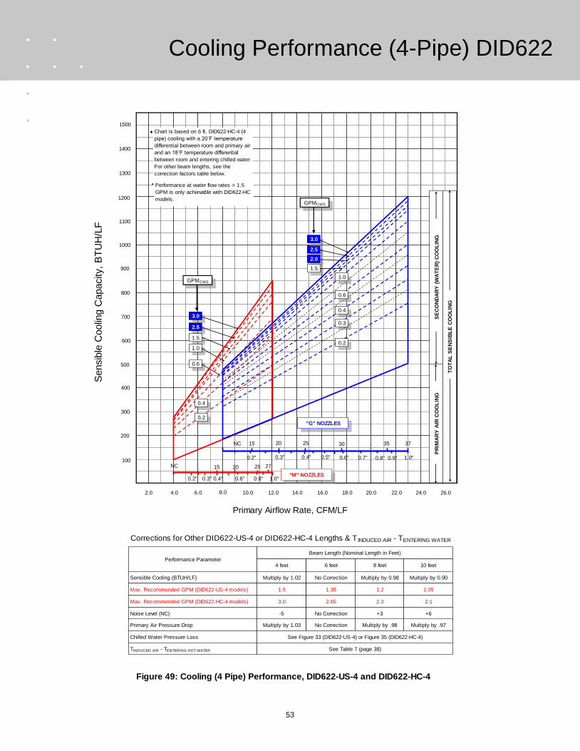
53
Figure 49: Cooling (4 Pipe) Performance, DID622-US-4 and DID622-HC-4
Corrections for Other DID622-US-4 or DID622-HC-4 Lengths & T INDUCED AIR - TENTERING WATER
Sensib
le C
oolin
g C
apacity,
BT
UH
/LF
1200
1000
900
800
700
600
500
1100
1300
400
300
Primary Airflow Rate, CFM/LF
4.0 6.0 16.0 26.010.08.0 20.018.012.0 14.0 22.0 24.0
200
2.0
100
PR
IMA
RY
AIR
CO
OL
ING
0.2" 0.3" 0.4" 0.6" 0.8" 1.0"
15 20 25 27NC
NC
0.3" 0.4" 0.5" 0.6" 0.7" 0.8" 0.9"
25 30 35 3720
1.0"0.2"
1400
1500
GPMCWS
SE
CO
ND
AR
Y (
WA
TE
R)
CO
OL
ING
TO
TA
L S
EN
SIB
LE
CO
OL
ING
Chart is based on 6 ft. DID622-HC-4 (4
pipe) cooling with a 20˚F temperature
differential between room and primary air
and an 18˚F temperature differential
between room and entering chilled water.
For other beam lengths, see the
correction factors table below.
Performance at water flow rates > 1.5
GPM is only achievable with DID622-HC
models.
2.5
1.5
1.0
0.6
GPMCWS
Performance Parameter4 feet 8 feet6 feet 10 feet
Beam Length (Nominal Length in Feet)
Multiply by 1.02 Multiply by 0.98No Correction Multiply by 0.90
-5 +3No Correction +6
Multiply by 1.03 Multiply by .98No Correction Multiply by .97
Sensible Cooling (BTUH/LF)
Noise Level (NC)
Primary Air Pressure Drop
Chilled Water Pressure Loss See Figure 33 (DID622-US-4) or Figure 35 (DID622-HC-4)
TINDUCED AIR - TENTERING HOT WATER See Table 7 (page 38)
1.5 1.21.35 1.05Max. Recommended GPM (DID622-US-4 models)
3.0 2.32.65 2.1Max. Recommended GPM (DID622-HC-4 models)
0.2
0.6
0.4
2.5
15
0.4
0.2
3.0
2.0
1.5
3.0
"G" NOZZLES
"M" NOZZLES
1.0
0.3
Cooling Performance (4-Pipe) DID622

54
Figure 50: Heating (4 Pipe) Performance, DID621-US-4 and DID621-HC-4
Net
Sensib
le H
eating C
apacity,
BT
UH
/LF
750
550
450
350
250
150
50
650
850
-50
-150
Primary Airflow Rate, CFM/LF
2.0 3.0 8.0 13.05.04.0 10.09.06.0 7.0 11.0 12.0
-250
1.0
0
PR
IMA
RY
AIR
CO
OL
ING
0.2" 0.3" 0.4" 0.6" 0.8" 1.0"
15 20 25 27NC
950
1050
NE
T S
EN
SIB
LE
H
EA
TIN
G
WA
TE
RS
IDE
H
EA
TIN
G
Chart is based on 6 ft. DID621-US-4 or
DID621-HC-4 (4 pipe) heating with a 20˚F
temperature differential between room
and primary air and an 50˚F temperature
differential between room and entering
hot water. For other beam lengths, see
the correction factors table below.
1.5
GPMHWS
"G" NOZZLES
"M" NOZZLES
0.6
1.0
0.4
0.3
0.2
GPMHWS
1.5
NC
0.3" 0.4" 0.5" 0.6" 0.7" 0.8" 0.9"
25 30 35 3720
1.0"0.2"
15
1.0
0.6
0.3
0.2
0.4
Performance Parameter4 Feet 8 Feet6 Feet 10 Feet
Beam Length (Nominal Length in Feet)
Multiply by 1.03 Multiply by 0.96No Correction Multiply by 0.92
-5 +3No Correction +6
Multiply by 1.03 Multiply by 0.98No Correction Multiply by 0.97
Water Side Heating (BTUH/LF)
Noise Level (NC)
Primary Air Pressure Drop
Hot Water Pressure Loss See Figure 36
TENTERING HOT WATER - TINDUCED AIR
Corrections for Other DID621-US-4 or DID621-HC-4 Lengths & TENTERING WATER - TINDUCED AIR
See table 7 (page 38)
1.5 1.51.5 1.5Max. Recommended GPM (DID621-US-4 models)
1.5 1.51.5 1.5Max. Recommended GPM (DID621-HC-4 models)
Heating Performance (4-Pipe) DID621
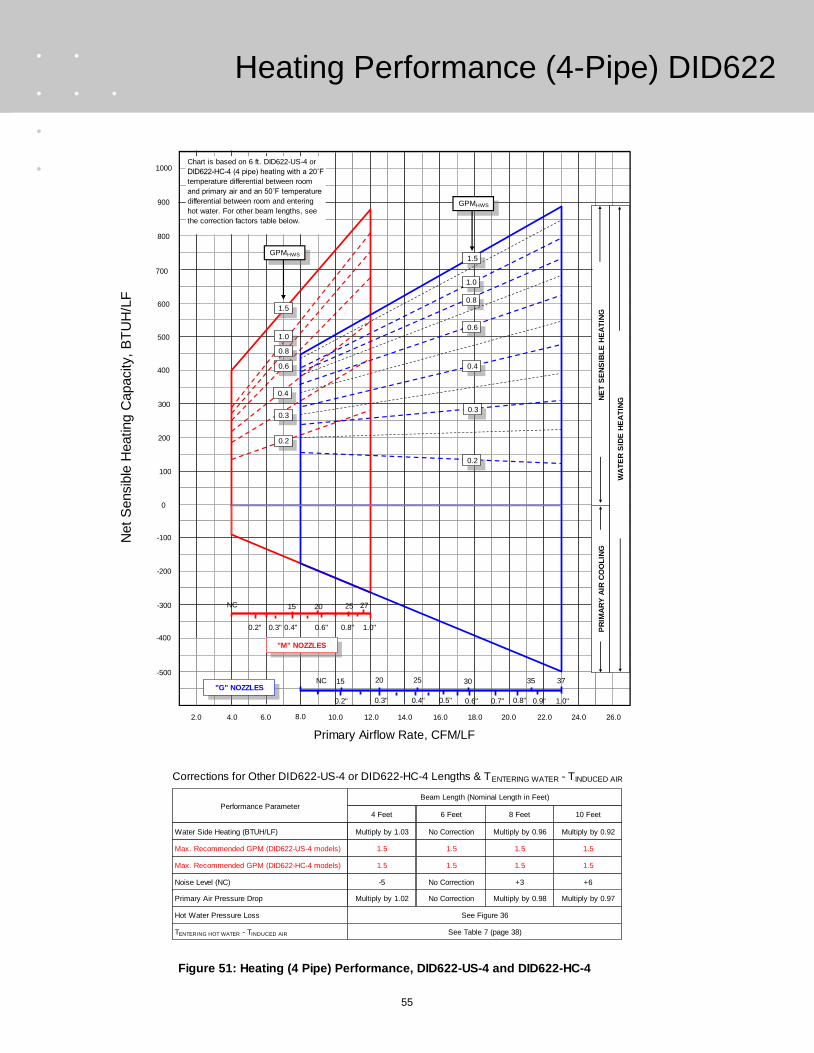
55
Figure 51: Heating (4 Pipe) Performance, DID622-US-4 and DID622-HC-4
Net
Sensib
le H
eating C
apacity,
BT
UH
/LF
700
500
400
300
200
100
0
600
800
-100
-200
Primary Airflow Rate, CFM/LF
4.0 6.0 16.0 26.010.08.0 20.018.012.0 14.0 22.0 24.0
-300
2.0
-400
900
1000
NE
T S
EN
SIB
LE
HE
AT
ING
0.3
0.2
PR
IMA
RY
AIR
CO
OL
ING
WA
TE
R S
IDE
HE
AT
ING
GPMHWS
1.0
0.6
0.4
0.3
0.2
0.6
0.4
Chart is based on 6 ft. DID622-US-4 or
DID622-HC-4 (4 pipe) heating with a 20˚F
temperature differential between room
and primary air and an 50˚F temperature
differential between room and entering
hot water. For other beam lengths, see
the correction factors table below.
"G" NOZZLES
"M" NOZZLES
NC
0.3" 0.4" 0.5" 0.6" 0.7" 0.8" 0.9"
25 30 35 3720
1.0"0.2"
15
0.2" 0.3" 0.4" 0.6" 0.8" 1.0"
15 20 25 27NC
-500
0.8
1.5
1.0
0.8
Performance Parameter4 Feet 8 Feet6 Feet 10 Feet
Beam Length (Nominal Length in Feet)
Multiply by 1.03 Multiply by 0.96No Correction Multiply by 0.92
-5 +3No Correction +6
Multiply by 1.02 Multiply by 0.98No Correction Multiply by 0.97
Water Side Heating (BTUH/LF)
Noise Level (NC)
Primary Air Pressure Drop
Hot Water Pressure Loss See Figure 36
TENTERING HOT WATER - TINDUCED AIR
Corrections for Other DID622-US-4 or DID622-HC-4 Lengths & TENTERING WATER - TINDUCED AIR
See Table 7 (page 38)
1.5 1.51.5 1.5Max. Recommended GPM (DID622-US-4 models)
1.5 1.51.5 1.5Max. Recommended GPM (DID622-HC-4 models)
GPMHWS1.5
Heating Performance (4-Pipe) DID622
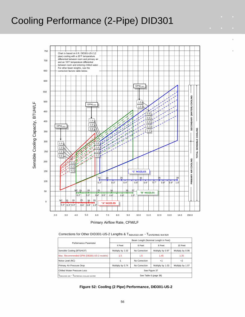
56
Figure 52: Cooling (2 Pipe) Performance, DID301-US-2
Performance Parameter4 Feet 8 Feet6 Feet 10 Feet
Beam Length (Nominal Length in Feet)
Multiply by 1.02 Multiply by 0.97No Correction Multiply by 0.95
-1 +1No Correction +2
Multiply by 0.74 Multiply by 1.03No Correction Multiply by 1.07
Sensible Cooling (BTUH/LF)
Noise Level (NC)
Primary Air Pressure Drop
Chilled Water Pressure Loss See Figure 37
TINDUCED AIR - TENTERING CHILLED WATER
Corrections for Other DID301-US-2 Lengths & T INDUCED AIR - TENTERING WATER
Sensib
le C
oolin
g C
apacity,
BT
UH
/LF
550
450
400
350
300
250
200
500
600
150
100
Primary Airflow Rate, CFM/LF
3.0 4.0 9.0 14.06.05.0 11.010.07.0 8.0 12.0 13.0
50
2.0
0
650
700
See Table 6 (page 38)
1.5 1.451.5 1.35Max. Recommended GPM (DID301-US-2 models)
750
150.0
Chart is based on 6 ft. DID301-US-2 (2
pipe) cooling with a 20˚F temperature
differential between room and primary air
and an 18˚F temperature differential
between room and entering chilled water.
For other beam lengths, see the
correction factors table below.
0.6" 0.7" 0.8" 0.9" 1.0"0.3" 0.4" 0.5"
25 30 35 39NC
"C" NOZZLES
PR
IMA
RY
AIR
CO
OL
ING
SE
CO
ND
AR
Y (
WA
TE
R)
CO
OL
ING
TO
TA
L S
EN
SIB
LE
CO
OL
ING
0.3" 0.4" 0.6" 0.8" 1.0"
15 20 25NC
"A" NOZZLES30 33
0.3"
NC
0.3"
20
0.4"
25
0.5" 0.6"
30
0.8" 1.0"
37"B" NOZZLES
3515
0.2"
20
0.2"
1.5
1.0
0.4
0.3
0.2
0.8
0.6
GPMCWS
GPMCWS
1.5
1.0
0.6
0.8
0.4
0.3
0.2
GPMCWS
1.5
0.8
1.0
0.6
0.4
0.3
0.2
Cooling Performance (2-Pipe) DID301

57
Figure 53: Cooling (2 Pipe) Performance, DID302-US-2
Performance Parameter4 Feet 8 Feet6 Feet 10 Feet
Beam Length (Nominal Length in Feet)
Multiply by 1.02 Multiply by 0.97No Correction Multiply by 0.95
-1 +1No Correction +2
Multiply by 0.74 Multiply by 1.03No Correction Multiply by 1.07
Sensible Cooling (BTUH/LF)
Noise Level (NC)
Primary Air Pressure Drop
Chilled Water Pressure Loss See Figure 37
TINDUCED AIR - TENTERING CHILLED WATER
Corrections for Other DID302-US-2 Lengths & T INDUCED AIR - TENTERING WATER
Sensib
le C
oolin
g C
apacity,
BT
UH
/LF
1100
900
800
700
600
500
400
1000
1200
300
200
Primary Airflow Rate, CFM/LF
6.0 8.0 18.0 28.012.010.0 22.020.014.0 16.0 24.0 26.0
100
4.0
0
1300
1400
See table 6 (page 38)
1.35 1.01.15 0.9Max. Recommended GPM (DID302-US-2 models)
1500
30.0
Chart is based on 6 ft. DID302-US-2 (2
pipe) cooling with a 20˚F temperature
differential between room and primary air
and an 18˚F temperature differential
between room and entering chilled water.
For other beam lengths, see the
correction factors table below.
0.6" 0.7" 0.8" 0.9" 1.0"0.3" 0.4" 0.5"
25 30 35 39NC
"C" NOZZLES
PR
IMA
RY
AIR
CO
OL
ING
SE
CO
ND
AR
Y (
WA
TE
R)
CO
OL
ING
TO
TA
L S
EN
SIB
LE
CO
OL
ING
GPMCWS
1.5
0.8
0.3
0.2
0.4
GPMCWS
GPMCWS
1.5
1.0
0.3" 0.4" 0.6" 0.8" 1.0"
15 20 25NC
"A" NOZZLES30 33
0.3"
NC
0.3"
20
0.4"
25
0.5" 0.6"
30
0.8" 1.0"
37"B" NOZZLES
3515
0.2"
20
0.2"
1.0
0.6
0.6
0.4
0.3
0.2
0.8
1.5
1.0
0.8
0.6
0.4
0.2
0.3
Cooling Performance (2-Pipe) DID302

58
Figure 54: Cooling (4 Pipe) Performance, DID301-US-4
Performance Parameter4 Feet 8 Feet6 Feet 10 Feet
Beam Length (Nominal Length in Feet)
Multiply by 1.02 Multiply by 0.97No Correction Multiply by 0.95
-1 +1No Correction +2
Multiply by 0.74 Multiply by 1.03No Correction Multiply by 1.07
Sensible Cooling (BTUH/LF)
Noise Level (NC)
Primary Air Pressure Drop
Chilled Water Pressure Loss See Figure 38
TINDUCED AIR - TENTERING CHILLED WATER
Corrections for Other DID301-US-4 Lengths & T INDUCED AIR - TENTERING WATER
Sensib
le C
oolin
g C
apacity,
BT
UH
/LF
550
450
400
350
300
250
200
500
600
150
100
Primary Airflow Rate, CFM/LF
3.0 4.0 9.0 14.06.05.0 11.010.07.0 8.0 12.0 13.0
50
2.0
0
650
700
See Table 6 (page 38)
1.5 1.51.5 1.5Max. Recommended GPM (DID301-US-4 models)
750
15.0
Chart is based on 6 ft. DID301-US-4 (4
pipe) cooling with a 20˚F temperature
differential between room and primary air
and an 18˚F temperature differential
between room and entering chilled water.
For other beam lengths, see the
correction factors table below.
0.6" 0.7" 0.8" 0.9" 1.0"0.3" 0.4" 0.5"
25 30 35 39NC
"C" NOZZLES
PR
IMA
RY
AIR
CO
OL
ING
SE
CO
ND
AR
Y (
WA
TE
R)
CO
OL
ING
TO
TA
L S
EN
SIB
LE
CO
OL
ING
0.3" 0.4" 0.6" 0.8" 1.0"
15 20 25NC
"A" NOZZLES30 33
0.3"
NC
0.3"
20
0.4"
25
0.5" 0.6"
30
0.8" 1.0"
37"B" NOZZLES
3515
0.2"
20
0.2"
GPMCWS
1.5
0.5
0.3
1.0
GPMCWS
1.5
0.5
0.3
1.0
GPMCWS
1.5
1.0
0.3
0.5
Cooling Performance (4-Pipe) DID301

59
Figure 55: Cooling (4 Pipe) Performance, DID302-US-4
Performance Parameter4 Feet 8 Feet6 Feet 10 Feet
Beam Length (Nominal Length in Feet)
Multiply by 1.02 Multiply by 0.97No Correction Multiply by 0.95
-1 +1No Correction +2
Multiply by 0.74 Multiply by 1.03No Correction Multiply by 1.07
Sensible Cooling (BTUH/LF)
Noise Level (NC)
Primary Air Pressure Drop
Chilled Water Pressure Loss See Figure 38
TINDUCED AIR - TENTERING CHILLED WATER
Corrections for Other DID302-US-2 Lengths & T INDUCED AIR - TENTERING WATER
Sensib
le C
oolin
g C
apacity,
BT
UH
/LF
1100
900
800
700
600
500
400
1000
1200
300
200
Primary Airflow Rate, CFM/LF
6.0 8.0 18.0 28.012.010.0 22.020.014.0 16.0 24.0 26.0
100
4.0
0
1300
1400
See Table 6 (page 38)
1.5 1.451.5 1.3Max. Recommended GPM (DID302-US-2 models)
1500
30.0
Chart is based on 6 ft. DID302-US-4 (4
pipe) cooling with a 20˚F temperature
differential between room and primary air
and an 18˚F temperature differential
between room and entering chilled water.
For other beam lengths, see the
correction factors table below.
0.6" 0.7" 0.8" 0.9" 1.0"0.3" 0.4" 0.5"
25 30 35 39NC
"C" NOZZLES
PR
IMA
RY
AIR
CO
OL
ING
SE
CO
ND
AR
Y (
WA
TE
R)
CO
OL
ING
TO
TA
L S
EN
SIB
LE
CO
OL
ING
GPMCWS
1.5
0.8
0.2
GPMCWS
GPMCWS
1.5
1.0
0.3" 0.4" 0.6" 0.8" 1.0"
15 20 25NC
"A" NOZZLES30 33
0.3"
NC
0.3"
20
0.4"
25
0.5" 0.6"
30
0.8" 1.0"
37"B" NOZZLES
3515
0.2"
20
0.2"
1.0
0.6
0.8
1.5
1.0
0.8
0.2
0.2
0.6
0.4
0.6
0.4
0.3
0.4
0.3
Cooling Performance (4-Pipe) DID302

60
Net
Sensib
le H
eating C
apacity,
BT
UH
/LF
300
200
150
100
50
0
-50
250
350
-150
-200
Primary Airflow Rate, CFM/LF
3.0 4.0 9.0 14.06.05.0 11.010.07.0 8.0 12.0 13.0
-250
2.0
400
450 Chart is based on 6 ft. DID301-US-4 (4
pipe) heating with a 20˚F temperature
differential between room and primary air
and an 50˚F temperature differential
between room and entering hot water.
For other beam lengths, see the
correction factors table below.
Figure 56: Heating (4 Pipe) Performance, DID301-US-4
PR
IMA
RY
AIR
CO
OL
ING
NE
T S
EN
SIB
LE
H
EA
TIN
G
WA
TE
RS
IDE
H
EA
TIN
G
Performance Parameter4 Feet 8 Feet6 Feet 10 Feet
Beam Length (Nominal Length in Feet)
Multiply by 1.03 Multiply by 0.96No Correction Multiply by 0.92
-1 +1No Correction +2
Multiply by 1.02 Multiply by 0.98No Correction Multiply by 0.97
Water Side Heating (BTUH/LF)
Noise Level (NC)
Primary Air Pressure Drop
Hot Water Pressure Loss See Figure 39
TENTERING HOT WATER - TINDUCED AIR
Corrections for Other DID301-US-4 Lengths & TENTERING WATER - TINDUCED AIR
See table 7 (page 38)
1.5 1.51.5 1.5Max. Recommended GPM (DID301-US-4 models)
0.6" 0.7" 0.8" 0.9" 1.0"0.3" 0.4" 0.5"
25 30 35 39NC
NC
0.3"
20
0.4"
25
0.5" 0.6"
30
0.8" 1.0"
37"B" NOZZLES
3515
0.2"
0.3" 0.4" 0.6" 0.8" 1.0"
15 20 25NC
"A" NOZZLES30 33
0.3"
"C" NOZZLES
GPMHWS
0.3
1.5
0.5
1.0
0.8
GPMHWS
0.3
0.8
1.5
0.5
1.0GPMHWS
0.3
1.5
0.5
1.0
0.8
Heating Performance (4-Pipe) DID301

61
Net
Sensib
le H
eating C
apacity,
BT
UH
/LF
400
200
100
0
-100
-200
-300
300
500
-400
-500
Primary Airflow Rate, CFM/LF
6.0 8.0 18.0 28.012.010.0 22.020.014.0 16.0 24.0 26.0
-600
4.0
600
700 Chart is based on 6 ft. DID302-US-4 (4 pipe) heating with
a 20˚F temperature differential between room and primary
air and an 50˚F temperature differential between room and
entering hot water. For other beam lengths, see the
correction factors table below.
Figure 57: Heating (4 Pipe) Performance, DID302-US-4
PR
IMA
RY
AIR
CO
OL
ING
NE
T S
EN
SIB
LE
H
EA
TIN
G
WA
TE
RS
IDE
H
EA
TIN
G
Performance Parameter4 Feet 8 Feet6 Feet 10 Feet
Beam Length (Nominal Length in Feet)
Multiply by 1.03 Multiply by 0.96No Correction Multiply by 0.92
-1 +1No Correction +2
Multiply by 1.02 Multiply by 0.98No Correction Multiply by 0.97
Water Side Heating (BTUH/LF)
Noise Level (NC)
Primary Air Pressure Drop
Hot Water Pressure Loss See Figure 39
TENTERING HOT WATER - TINDUCED AIR
Corrections for Other DID302-US-4 Lengths & TENTERING WATER - TINDUCED AIR
See Table 7 (page 38)
1.5 1.51.5 1.5Max. Recommended GPM (DID302-US-4 models)
0.6" 0.7" 0.8" 0.9" 1.0"0.3" 0.4" 0.5"
25 30 35 39NC
NC
0.3"
20
0.4"
25
0.5" 0.6"
30
0.8" 1.0"
37"B" NOZZLES
3515
0.2"
0.3" 0.4" 0.6" 0.8" 1.0"
15 20 25NC
"A" NOZZLES30 33
0.3"
"C" NOZZLES
GPMHWS
1.0
0.4
0.8
1.5
0.6
0.4
1.5
1.0
0.8
0.6
GPMHWS
1.5
1.0
0.8
0.6
0.4
GPMHWS
Heating Performance (4-Pipe) DID302

62
Specification DID600
DID600 Series Active Chilled Beams PART 1- GENERAL 1.01 Summary This section describes the active chilled beams. 1.02 Submittals Submit product data for all items complete with the following information: 1. Operating weights and dimensions of all unit
assemblies. 2. Performance data, including sensible and latent
cooling capacities, nozzle types, primary and total supply (primary plus induced) airflow rates, chilled (and where applicable hot) water flow rates, noise levels in octave bands, air and water side pressure losses and maximum discharge air throw values.
3. Construction details including manufacturers recommendations for installation, mounting and connection.
PART 2- PRODUCTS 2.01 General Materials and products required for the work of this section shall not contain asbestos, polychlorinated biphenyls (PCB) or other hazardous materials identified by the engineer or owner. Approved Manufacturers: These specifications set forth the minimum requirements for the active chilled beams to be accepted for this project. Products provided by the following manufacturers will be deemed acceptable provided they meet all of the construction and performance requirements of this specification: 1. TROX 2.02 Design 1. Furnish and install TROX DID601 and/or DID602
series active chilled beams of sizes and capacities as indicated on the drawings and within the mechanical equipment schedules. The quantity and length of the beams shall be as shown on the drawings, without EXCEPTION. The beams shall be constructed and delivered to the job site as single units.
2. The face of the beam shall consist of a room air induction section of 50% free area perforated
steel flanked by two linear supply slots. The entire visible face section shall be finished in white powder coat paint or as specified by the architect. All visible internal surfaces shall be flat black. The face of the beam shall be hinged for easy access to internal components.
3. Beams shall be provided with side and end details which will allow its integration into the applicable (nominal 24 inch wide) acoustical ceiling grid as specified by the architect. Beams used for exposed mounting applications shall include factory mounted Coanda plates to assure a horizontal discharge of the supply air.
4. The beams shall consist of a minimum 20 gauge galvanized steel housing encasing the integral sensible cooling coil and a plenum feeding a series of induction nozzles. A side or end mounted connection spigot shall afford the connection of a primary air supply duct (4” nominal diameter for all one way beams and 2 way beams through six feet in length, 5” nominal diameter for 2 way beams longer than six feet) The overall height of the beams shall not exceed 9¾ inches.
5. Beams shall incorporate provisions for measurement of their primary airflow rate. The measurement location must be accessible from the face of the beam and require a single pressure differential measurement. Airflow calibration charts that relate the measurement to the primary airflow rate shall be furnished with the beams.
6. (OPTIONAL) Each beam shall be furnished with a separate volume flow limiter for mounting in the primary air duct by the installing contractor. This device shall allow field adjustment of a maximum primary air flow rate that is maintained independent of any static pressure changes in the inlet ductwork. The volume flow limiter shall add no more than 0.20 inches H2O pressure drop to the primary air delivery system and shall not require any control or power connections.
7. Beams shall be provided with connections for either 2 or 4 pipe operation as indicated on plans and schedules. Four pipe configurations shall require separate supply and return connections for chilled and hot water. The coils shall be mounted horizontally and shall be manufactured with seamless copper tubing (½” outside diameter) with minimum .025 inch wall thickness mechanically fixed to aluminum fins. The aluminum fins shall be limited to no more than ten (10) fins per inch. The beam shall have a working pressure of at least 300 PSI, be factory tested for leakage at a minimum pressure of 360 PSI. Each chilled beam shall be provided with factory integrated drain fittings. Each chilled beam shall be provided with factory integrated
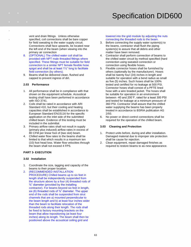
63
Specification DID600
vent and drain fittings. Unless otherwise specified, coil connections shall be bare copper for field sweating to the water supply circuit. Connections shall face upwards, be located near the left end of the beam (when viewing into the primary air connection
8. (OPTIONAL) The chilled water coil shall be provided with NPT male threaded fittings where specified. These fittings must be suitable for field connection to a similar NPT female flexible hose spigot and shall be at least 1½” long to facilitate field connection (by others).
9. Beams shall be delivered clean, flushed and capped to prevent ingress of dirt.
2.03 Performance 1. All performance shall be in compliance with that
shown on the equipment schedule. Acoustical testing shall have been performed in accordance with ISO 3741.
2. Coils shall be rated in accordance with ARI Standard 410, but their cooling and heating capacities shall be established in accordance to European Standard EN15116 for the specific application on the inlet side of the submitted chilled beam. Evidence of this testing must be included in the submittal.
3. Primary airflow rates shall not result in supply (primary plus induced) airflow rates in excess of 80 CFM per linear foot of (two slot) beam.
4. Chilled water flow rates to the beams shall be limited to that which results in a maximum ten (10) foot head loss. Water flow velocities through the beam shall not exceed 4 FPS.
PART 3- EXECUTION 3.02 Installation 1. Coordinate the size, tagging and capacity of the
beams to their proper location. 2. (RECOMMENDED INSTALLATION
PROCEDURE) Chilled beams up to six feet in length shall be independently suspended from the structure above by a four (4) threaded rods of ⅜” diameter (provided by the installing contractor). For beams beyond six feet in length, six (6) threaded rods of ⅜” diameter. The upper end of the rods shall be suspended from strut channels that are a) mounted perpendicular to the beam length and b) at least four inches wider than the beam to facilitate relocation of the threaded rods along their length. The rods shall be fixed to factory mounting brackets on the beam that allow repositioning (at least four inches) along its length. The beam shall then be positioned above the acoustical ceiling grid and
lowered into the grid module by adjusting the nuts connecting the threaded rods to the beam.
3. Before connecting the supply water system(s) to the beams, contractor shall flush the piping system(s) to assure that all debris and other matter have been removed.
4. Contractor shall perform connection of beams to the chilled water circuit by method specified (hard connection using sweated connection or connection using flexible hoses.
5. Flexible connector hoses shall be furnished by others (optionally by the manufacturer). Hoses shall be twenty four (24) inches in length and suitable for operation with a bend radius as small as five (5) inches. Such hoses shall be 100% tested and certified for no leakage at 500 PSI. Connector hoses shall consist of a PFTE lined hose with a wire braided jacket. The hoses shall be suitable for operation in an environment between -40 and 200˚F, rated for a least 300 PSI and tested for leakage at a minimum pressure of 360 PSI. Contractor shall assure that the chilled water supplying the beams has been properly treated in accordance to BSRIA publication AG 2/93.
6. No power or direct control connections shall be required for the operation of the chilled beam.
3.03 Cleaning and Protection 1. Protect units before, during and after installation.
Damaged material due to improper site protection shall be cause for rejection.
2. Clean equipment, repair damaged finishes as required to restore beams to as-new appearance.

64
Specification DID620
DID620 Series Active Chilled Beams PART 1- GENERAL 1.01 Summary This section describes the active chilled beams. 1.02 Submittals Submit product data for all items complete with the following information: 1. Operating weights and dimensions of all unit
assemblies. 2. Performance data, including sensible and latent
cooling capacities, nozzle types, primary and total supply (primary plus induced) airflow rates, chilled (and where applicable hot) water flow rates, noise levels in octave bands, air and water side pressure losses and maximum discharge air throw values.
3. Construction details including manufacturers recommendations for installation, mounting and connection.
PART 2- PRODUCTS 2.01 General Materials and products required for the work of this section shall not contain asbestos, polychlorinated biphenyls (PCB) or other hazardous materials identified by the engineer or owner. Approved Manufacturers: These specifications set forth the minimum requirements for the active chilled beams to be accepted for this project. Products provided by the following manufacturers will be deemed acceptable provided they meet all of the construction and performance requirements of this specification: 1. TROX 2.02 Design 1. Furnish and install TROX DID621 (1 slot) and/or
DID622 (2 slot) series single slot active chilled beams of sizes and capacities as indicated on the drawings and within the mechanical equipment schedules. The quantity and length of the beams shall be as shown on the drawings, without EXCEPTION. The beams shall be constructed and delivered to the job site as single units.
2. The face of the beam shall consist of a room air induction section of 50% free area perforated steel flanked by two linear supply slots. The
entire visible face section shall be finished in white powder coat paint or as specified by the architect. All visible internal surfaces shall be flat black.
3. Beams shall be provided with side and end details which will allow its integration into the applicable (nominal 24 inch wide) acoustical ceiling grid as specified by the architect. Beams used for exposed mounting applications shall include factory mounted Coanda plates to assure a horizontal discharge of the supply air.
4. The beams shall consist of a minimum 20 gauge galvanized steel housing encasing the integral sensible cooling coil and a plenum feeing a series of induction nozzles. A side (model 622-US-H) or top (model 622-US-V) mounted connection spigot shall afford the connection of a six (6) inch diameter supply air. The overall height of beams shall not exceed 8⅞ inches.
5. Each beam shall be provided with a pressure tap that may be used to measure the pressure differential between the primary air plenum and the room. Airflow calibration charts that relate this pressure differential reading with the primary and beam supply airflow rates shall be furnished with the beams.
6. (OPTIONAL) Each beam shall be furnished with a separate volume flow limiter for mounting in the primary air duct by the installing contractor. This device shall allow field adjustment of a maximum primary air flow rate that is maintained independent of any static pressure changes in the inlet ductwork. The volume flow limiter shall add no more than 0.20 inches H2O pressure drop to the primary air delivery system and shall not require any control or power connections.
7. Beams shall be provided with connections for either 2 or 4 pipe operation as indicated on plans and schedules. Four pipe configurations shall require separate supply and return connections for chilled and hot water. The coils shall be mounted horizontally and shall be manufactured with seamless copper tubing (½” outside diameter) with minimum .025 inch wall thickness mechanically fixed to aluminum fins. The aluminum fins shall be limited to no more than ten (10) fins per inch. The beam shall have a working pressure of at least 300 PSI, be factory tested for leakage at a minimum pressure of 360 PSI. Each chilled beam shall be provided with factory integrated vent and drain fittings. Unless otherwise specified, coil connections shall be bare copper for field sweating to the water supply circuit. Connections shall face upwards, be located near the left end of the beam (when viewing into the primary air connection

65
Specification DID620
8. (OPTIONAL) The chilled water coil shall be provided with NPT male threaded fittings where specified. These fittings must be suitable for field connection to a similar NPT female flexible hose spigot and shall be at least 1½” long to facilitate field connection (by others).
9. Beams shall be delivered clean, flushed and capped to prevent ingress of dirt
2.03 Performance 1. All performance shall be in compliance with that
shown on the equipment schedule. Acoustical testing shall have been performed in accordance with ISO 3741.
2. Coils shall be rated in accordance with ARI Standard 410, but their cooling and heating capacities shall be established in accordance to European Standard EN15116 for the specific application on the inlet side of the submitted chilled beam. Evidence of this testing must be included in the submittal.
3. 4. Primary airflow rates shall not result in supply
(primary plus induced) airflow rates in excess of 80 CFM per linear foot of beam.
5. Chilled water flow rates to the beams shall be limited to that which results in a maximum ten (10) foot head loss. Water flow velocities through the beam shall not exceed 4 FPS.
PART 3- EXECUTION 3.02 Installation 1. Coordinate the size, tagging and capacity of the
beams to their proper location. 2. (RECOMMENDED INSTALLATION
PROCEDURE) Chilled beams up to six feet in length shall be independently suspended from the structure above by a four (4) threaded rods of ⅜” diameter (provided by the installing contractor). For beams beyond six feet in length, six (6) threaded rods of ⅜” diameter. The upper end of the rods shall be suspended from strut channels that are a) mounted perpendicular to the beam length and b) at least four inches wider than the beam to facilitate relocation of the threaded rods along their length. The rods shall be fixed to factory mounting slots on the beam that allow repositioning (at least four inches) along its length. The beam shall then be positioned above the acoustical ceiling grid and lowered into the grid module by adjusting the nuts connecting the threaded rods to the beam.
3. Before connecting the supply water system(s) to the beams, contractor shall flush the piping system(s) to assure that all debris and other matter have been removed.
4. Contractor shall perform connection of beams to the chilled water circuit by method specified (hard connection using sweated connection or connection using flexible hoses.
5. Flexible connector hoses shall be furnished by others (optionally by the manufacturer). Hoses shall be twenty four (24) inches in length and suitable for operation with a bend radius as small as five (5) inches. Such hoses shall be 100% tested and certified for no leakage at 500 PSI. Connector hoses shall consist of a PFTE lined hose with a wire braided jacket. The hoses shall be suitable for operation in an environment between -40 and 200˚F, rated for a least 300 PSI and tested for leakage at a minimum pressure of 360 PSI. Contractor shall assure that the chilled water supplying the beams has been properly treated in accordance to BSRIA publication AG 2/93.
6. No power or direct control connections shall be required for the operation of the chilled beam.
3.03 Cleaning and Protection 1. Protect units before, during and after installation.
Damaged material due to improper site protection shall be cause for rejection.
2. Clean equipment, repair damaged finishes as required to restore beams to as-new appearance.
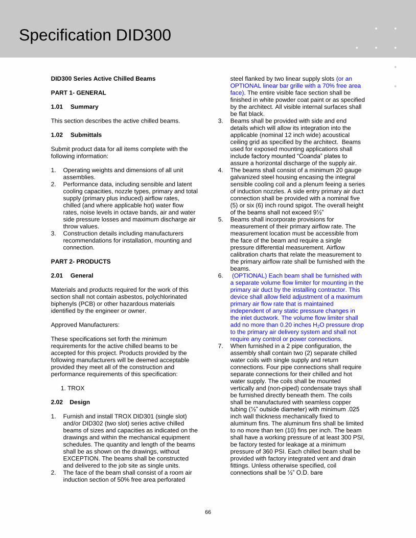
66
DID300 Series Active Chilled Beams PART 1- GENERAL 1.01 Summary This section describes the active chilled beams. 1.02 Submittals Submit product data for all items complete with the following information: 1. Operating weights and dimensions of all unit
assemblies. 2. Performance data, including sensible and latent
cooling capacities, nozzle types, primary and total supply (primary plus induced) airflow rates, chilled (and where applicable hot) water flow rates, noise levels in octave bands, air and water side pressure losses and maximum discharge air throw values.
3. Construction details including manufacturers recommendations for installation, mounting and connection.
PART 2- PRODUCTS 2.01 General Materials and products required for the work of this section shall not contain asbestos, polychlorinated biphenyls (PCB) or other hazardous materials identified by the engineer or owner. Approved Manufacturers: These specifications set forth the minimum requirements for the active chilled beams to be accepted for this project. Products provided by the following manufacturers will be deemed acceptable provided they meet all of the construction and performance requirements of this specification: 1. TROX 2.02 Design 1. Furnish and install TROX DID301 (single slot)
and/or DID302 (two slot) series active chilled beams of sizes and capacities as indicated on the drawings and within the mechanical equipment schedules. The quantity and length of the beams shall be as shown on the drawings, without EXCEPTION. The beams shall be constructed and delivered to the job site as single units.
2. The face of the beam shall consist of a room air induction section of 50% free area perforated
steel flanked by two linear supply slots (or an OPTIONAL linear bar grille with a 70% free area face). The entire visible face section shall be finished in white powder coat paint or as specified by the architect. All visible internal surfaces shall be flat black.
3. Beams shall be provided with side and end details which will allow its integration into the applicable (nominal 12 inch wide) acoustical ceiling grid as specified by the architect. Beams used for exposed mounting applications shall include factory mounted “Coanda” plates to assure a horizontal discharge of the supply air.
4. The beams shall consist of a minimum 20 gauge galvanized steel housing encasing the integral sensible cooling coil and a plenum feeing a series of induction nozzles. A side entry primary air duct connection shall be provided with a nominal five (5) or six (6) inch round spigot. The overall height of the beams shall not exceed 9½”
5. Beams shall incorporate provisions for measurement of their primary airflow rate. The measurement location must be accessible from the face of the beam and require a single pressure differential measurement. Airflow calibration charts that relate the measurement to the primary airflow rate shall be furnished with the beams.
6. (OPTIONAL) Each beam shall be furnished with a separate volume flow limiter for mounting in the primary air duct by the installing contractor. This device shall allow field adjustment of a maximum primary air flow rate that is maintained independent of any static pressure changes in the inlet ductwork. The volume flow limiter shall add no more than 0.20 inches H2O pressure drop to the primary air delivery system and shall not require any control or power connections.
7. When furnished in a 2 pipe configuration, the assembly shall contain two (2) separate chilled water coils with single supply and return connections. Four pipe connections shall require separate connections for their chilled and hot water supply. The coils shall be mounted vertically and (non-piped) condensate trays shall be furnished directly beneath them. The coils shall be manufactured with seamless copper tubing (½” outside diameter) with minimum .025 inch wall thickness mechanically fixed to aluminum fins. The aluminum fins shall be limited to no more than ten (10) fins per inch. The beam shall have a working pressure of at least 300 PSI, be factory tested for leakage at a minimum pressure of 360 PSI. Each chilled beam shall be provided with factory integrated vent and drain fittings. Unless otherwise specified, coil connections shall be ½” O.D. bare
Specification DID300
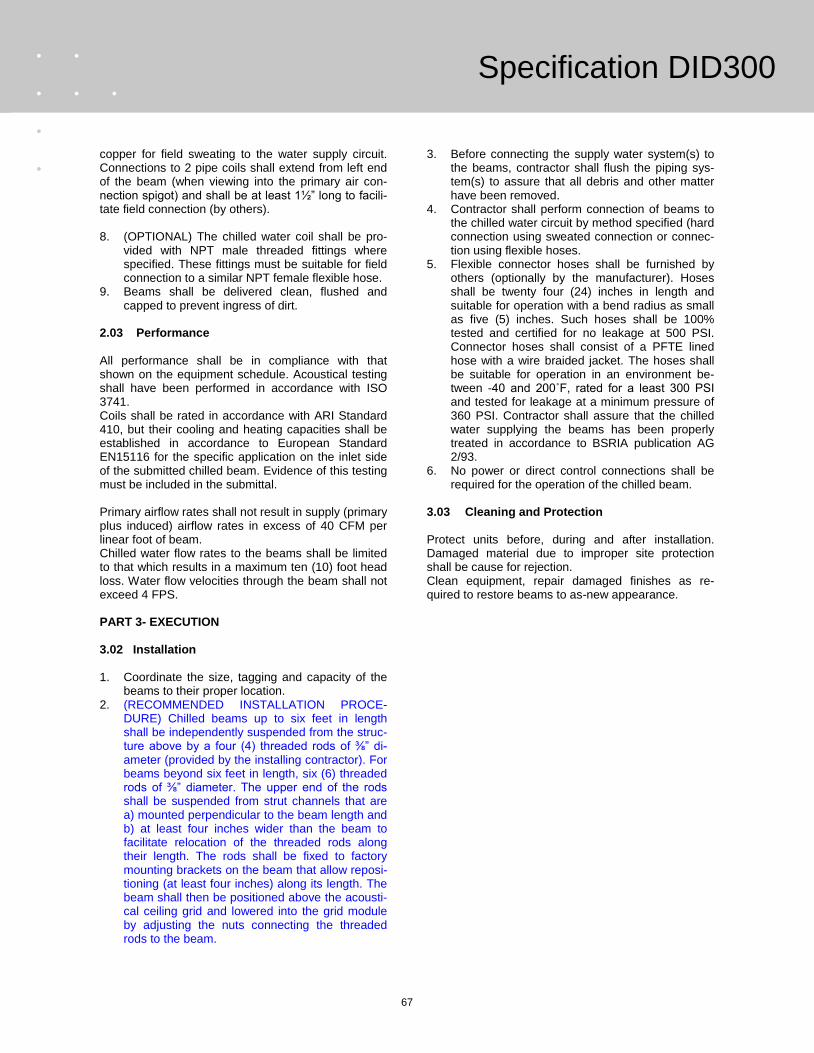
67
copper for field sweating to the water supply circuit. Connections to 2 pipe coils shall extend from left end of the beam (when viewing into the primary air con-nection spigot) and shall be at least 1½” long to facili-tate field connection (by others). 8. (OPTIONAL) The chilled water coil shall be pro-
vided with NPT male threaded fittings where specified. These fittings must be suitable for field connection to a similar NPT female flexible hose.
9. Beams shall be delivered clean, flushed and capped to prevent ingress of dirt.
2.03 Performance All performance shall be in compliance with that shown on the equipment schedule. Acoustical testing shall have been performed in accordance with ISO 3741. Coils shall be rated in accordance with ARI Standard 410, but their cooling and heating capacities shall be established in accordance to European Standard EN15116 for the specific application on the inlet side of the submitted chilled beam. Evidence of this testing must be included in the submittal. Primary airflow rates shall not result in supply (primary plus induced) airflow rates in excess of 40 CFM per linear foot of beam. Chilled water flow rates to the beams shall be limited to that which results in a maximum ten (10) foot head loss. Water flow velocities through the beam shall not exceed 4 FPS. PART 3- EXECUTION 3.02 Installation 1. Coordinate the size, tagging and capacity of the
beams to their proper location. 2. (RECOMMENDED INSTALLATION PROCE-
DURE) Chilled beams up to six feet in length shall be independently suspended from the struc-ture above by a four (4) threaded rods of ⅜” di-ameter (provided by the installing contractor). For beams beyond six feet in length, six (6) threaded rods of ⅜” diameter. The upper end of the rods shall be suspended from strut channels that are a) mounted perpendicular to the beam length and b) at least four inches wider than the beam to facilitate relocation of the threaded rods along their length. The rods shall be fixed to factory mounting brackets on the beam that allow reposi-tioning (at least four inches) along its length. The beam shall then be positioned above the acousti-cal ceiling grid and lowered into the grid module by adjusting the nuts connecting the threaded rods to the beam.
3. Before connecting the supply water system(s) to the beams, contractor shall flush the piping sys-tem(s) to assure that all debris and other matter have been removed.
4. Contractor shall perform connection of beams to the chilled water circuit by method specified (hard connection using sweated connection or connec-tion using flexible hoses.
5. Flexible connector hoses shall be furnished by others (optionally by the manufacturer). Hoses shall be twenty four (24) inches in length and suitable for operation with a bend radius as small as five (5) inches. Such hoses shall be 100% tested and certified for no leakage at 500 PSI. Connector hoses shall consist of a PFTE lined hose with a wire braided jacket. The hoses shall be suitable for operation in an environment be-tween -40 and 200˚F, rated for a least 300 PSI and tested for leakage at a minimum pressure of 360 PSI. Contractor shall assure that the chilled water supplying the beams has been properly treated in accordance to BSRIA publication AG 2/93.
6. No power or direct control connections shall be required for the operation of the chilled beam.
3.03 Cleaning and Protection Protect units before, during and after installation. Damaged material due to improper site protection shall be cause for rejection. Clean equipment, repair damaged finishes as re-quired to restore beams to as-new appearance.
Specification DID300

68
In North America Trox USA, Inc. 4305 Settingdown Circle Cumming Georgia USA 30028 Telephone: (770) 569-1433 Telefax: (770) 569-1435 e-mail: [email protected] www.troxusa.com
Head Office & Research Centers Gebrüder Trox GmbH Postfach 10 12 63 D-47504 Neukirchen-Vluyn Telephone 49 28 45/2 02-0 Telefax 49 28 45/2 02-2 65 www.troxtechnik.com E-mail: [email protected]
Australia Trox (Australia) Pty Ltd. Austria Trox Austria GmbH Belgium S.A. Trox Belgium N.V. Brazil Trox do Brasil Ltda. China Trox Air Conditioning Components (Suzhou) Co., Ltd. Croatia Trox Austria GmbH
Czech Republic Trox Austria GmbH Denmark Trox Danmark A/S Dubai Trox (U.K.) Ltd. France Trox France Sarl Germany Hesco Deutschland GmbH FSL FassadenSystemLüftung GmbH & Co. KG Great Britain Trox (U.K.) Ltd.
Hong Kong Trox Hong Kong Ltd. Hungary Trox Austria GmbH Italy Trox Italiana S.p.A. Malaysia Trox (Malaysia) Sdn. Bhd. Norway Auranor Group AS Poland Trox Austria GmbH
South Africa Trox (South Africa) (Pty) Ltd. Spain Trox Española, S.A. Switzerland Trox Hesco (Schweiz) AG Yugoslavia Trox Austria GmbH
Design changes reserved · All rights reserved © Gebrüder Trox GmbH (01/2009)