Chemilizer Products, Inc. Product Manual · Chemilizer Products, Inc. Product Manual We are...
37
For the latest updates or modifications, please check our website at: www.chemilizer.com Chemilizer Products, Inc. Product Manual We are committed to building the BEST quality product you can buy. If you should need to ask a question or need further technical, sales, or service assistance, please contact us! Chemilizer Products Corporate Office: 230 Commerce Drive North, Largo, Florida 33770 Toll free: 1.800.234.7211 Fax: 727.559.8266 If you would like to contact us via email, use the following email address that corresponds to your needs: Customer Feedback: [email protected] General Information: [email protected] Product Questions: [email protected] Questions about Warranty: [email protected] To Become a Dealer: [email protected] Repair Assistance: [email protected] Web Site Questions: [email protected] We invite you to visit our website: www.chemilizer.com 1.800.234.7211 (1)
Transcript of Chemilizer Products, Inc. Product Manual · Chemilizer Products, Inc. Product Manual We are...
For the latest updates or modifications, please check our website at: www.chemilizer.com
Chemilizer Products, Inc. Product Manual
We are committed to building the BEST quality product you can buy. If you should need to ask a question or need further technical, sales, or service assistance, please contact us!
Chemilizer Products Corporate Office:230 Commerce Drive North, Largo, Florida 33770
Toll free: 1.800.234.7211Fax: 727.559.8266
If you would like to contact us via email, use the following email address that corresponds to your needs:
Customer Feedback: [email protected] Information: [email protected] Questions: [email protected] about Warranty: [email protected] Become a Dealer: [email protected] Assistance: [email protected] Site Questions: [email protected]
We invite you to visit our website: www.chemilizer.com1.800.234.7211
(1)
Table of Contents
Page
1. Precautions 32. Getting Started – What you need to know before you install your new Chemilizer injector a. How it Works 4 b. Identification of the Key External Parts 4 c. Additional Equipment 43. How to Identify the Injector Model You’ve Purchased a. HN55 Injector 5 b. CP33 Injector with Control Panel 5 c. C3P Portable Sprayer 64. How to Install and Use the Injector 7 a. Pre-Assembly 7 b. Safety 8 c. C3P 9 d. HN55 Basic Installation 10 e. CP33 Basic Installation 12, 13, 14 f. Application Specific Installation Guidelines: i. Animal Health 15 ii. Horticulture 15 iii. Landscaping 15 v. Water Treatment 1) Wells 16 2) Municipal 16 iv. Pools 17, 18, 195. How to Determine your Chemical Mix a. HN55 20 b. CP33 216. Trouble Shooting Tips a. HN55 – Water motor 22 b. CP33 – Water motor & Injection Control Panel 23 c. Chemical Pump 257. Maintenance Tips 26 8. Frequently Asked Questions (FAQs) 27, 289. Technical Specifications 2910. Replacement Parts 3011. Warranty 3612. Contact Us 37
(2)

Thank you for purchasing a Chemilizer injector!
Chemilizer is committed to manufacturing the highest quality product to fill your injection needs, and to providing you with the best service possible. To help us achieve this, we ask that you please take a moment to fill out and send in the warranty card. Or you can also fill out the warranty online at our web site, www.chemilizer.com.
1. PrecautionsWarning! Risk of Chemical OverdoseTo reduce risk, follow proper installation methods and instructions. [The point of chemical injection should be beyond all pumps, filters and heaters. Needs to in pool section, not here. – What about landscaping, and water treatment applications?!]
Caution! PlumbingChemilizer injector installations must always adhere to your local plumbing codes and requirements. Check local plumbing codes for guidelines.
Notice:
The Chemilizer injector is a general purpose injector. It was not designed to inject acid. However, some customers use it to inject acids of varying concentrations because our design limits the “dam-age” caused by aggressive chemicals to the pump, which is inexpensive to repair or replace. Our pump is resistant to chemicals of varying concentrations and a wide range of pH. However, more cor-rosive chemicals will degrade pump parts faster, necessitating more frequent repair or replacement, adding an additional amount to the cost of using our injectors with that chemical or group of chemi-cals. Pump life is determined by a number of factors that include duty cycle, chemical(s) being injected, and frequency of cleaning, among others. Therefore each customer’s experience will be different. Normally the check valve, the pump stem and stem o-rings degrade first with the ceramic sleeve taking longer to be affected. Therefore, a pump rebuild kit will be the most frequent maintenance for customers using aggressive chemicals.
Notice:Components of Chemilizer Injectors have been tested for tolerance to a wide variety of chemical com-pounds at common solution strengths. Chemilizer Injectors provide a means of delivery for chemicals in general. Chemilizer does not suggest or recommend ways or procedures for using or handling any chemical.
As required by NSF, please be advised that this injection system and its components have been tested for use in swimming pools with the following chemicals:
Sodium Hypochlorite (10-15%), Muriatic Acid (20 Baume/31.5%), HeatsavrTM
Chemilizer Products, Inc. is not responsible for injury incurred by the misuse or improper handling of chemicals.
(3)

2. Getting Started
– What you need to know before you install your new Chemilizer injector
A. How it Works
The Chemilizer injector is powered by water. A continuous flow of water through the blue Water Mo-tor activates the movement of an internal diaphragm assembly, which then powers the white Chemi-cal Pump. The Chemical Pump injects solution into the water after the water has passed through the Water Motor; the solution never passes through the blue Water Motor.
The higher the water flow, the faster the diaphragm assembly moves, the faster the pump works. If the water flow stops, so does the pump and consequently the injection of solution into the water.
B. Identification of key external parts:
There are two or three key components to the Chemilizer, depending on the model you’ve purchased. Detailed identification of the parts can be found in Section 3 of this manual.
The blue Water Motor contains the diaphragm mechanism.
The clear Injection Control Panel (which is only on the CP33) provides variable control of the injection volume.
The white Chemical Pump draws solu-tion from your container and injects it directly into the water source.
Water Motor(Blue)
Injection Control Panel(Clear)On the CP33 only!
Chemical Pump(White)
C. Additional Equipment
The best method for installation of the injector depends on the model you’ve purchased and how you want to use it. Please reference Section 4 of this manual for installation guidelines.
All of Chemilizer’s recommended installation configurations require commonly available additional components, such as PVC pipe, adapters, hoses and valves. Most of these can be procured locally, should you prefer, Chemilizer offers “Installation Kits” to ensure you have everything you need. If you haven’t purchased an installation kit, please see your Chemilizer dealer or contact Chemilizer directly at 1-800-234-7211.
(4)
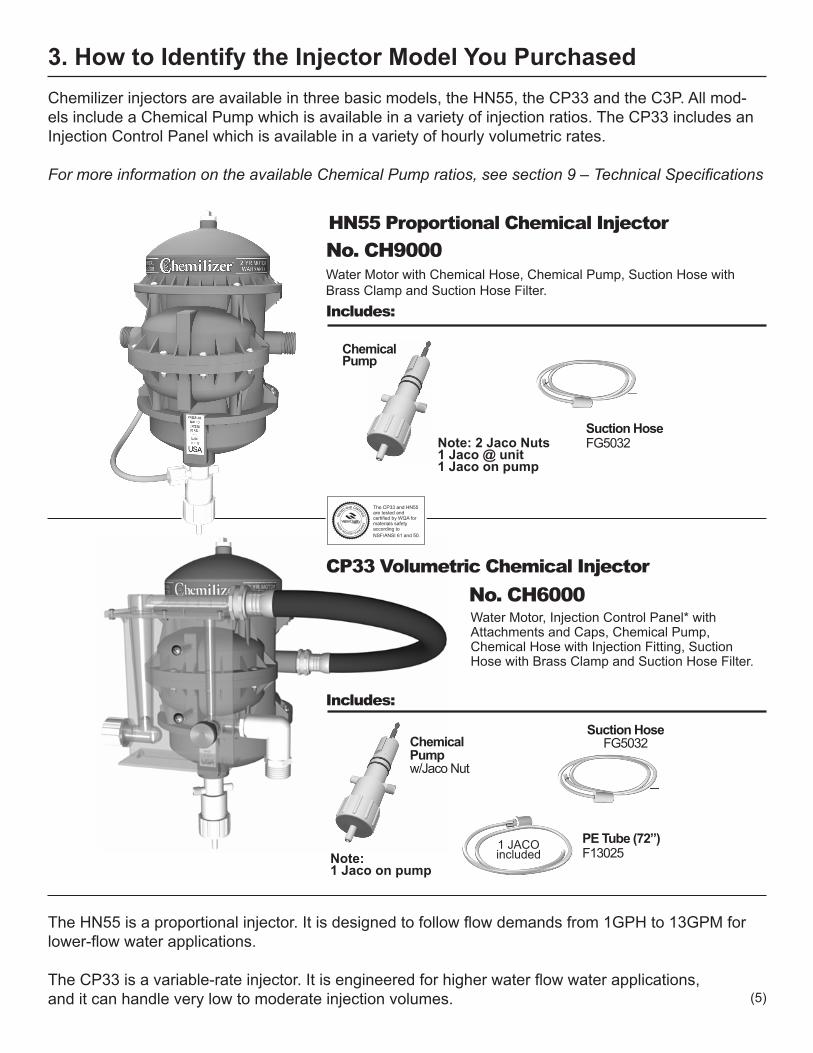
3. How to Identify the Injector Model You PurchasedChemilizer injectors are available in three basic models, the HN55, the CP33 and the C3P. All mod-els include a Chemical Pump which is available in a variety of injection ratios. The CP33 includes an Injection Control Panel which is available in a variety of hourly volumetric rates.
For more information on the available Chemical Pump ratios, see section 9 – Technical Specifications
The CP33 and HN55 are tested and certified by WQA for materials safety according to NSF/ANSI 61 and 50.
Water Motor with Chemical Hose, Chemical Pump, Suction Hose with Brass Clamp and Suction Hose Filter.
HN55 Proportional Chemical InjectorNo. CH9000
Includes:
ChemicalPump
Includes:
ChemicalPumpw/Jaco Nut
PE Tube (72”)F13025
Water Motor, Injection Control Panel* with Attachments and Caps, Chemical Pump, Chemical Hose with Injection Fitting, Suction Hose with Brass Clamp and Suction Hose Filter.
CP33 Volumetric Chemical InjectorNo. CH6000
Suction HoseFG5032
Suction HoseFG5032
1 JACO included
Note: 2 Jaco Nuts1 Jaco @ unit1 Jaco on pump
Note: 1 Jaco on pump
The HN55 is a proportional injector. It is designed to follow flow demands from 1GPH to 13GPM for lower-flow water applications.
The CP33 is a variable-rate injector. It is engineered for higher water flow water applications, and it can handle very low to moderate injection volumes. (5)

ChemicalPump
ChemicalPumpw/Jaco Nut
HN55 Chemical Tank, Chemical Tank Cap, Spray Nozzle, Spray Nozzle Hose, Spray Nozzle Quick Release, Tank Quick Release Pins, Strap Hardware.
FGKT1520Tank Cap
FGKT1500Tank
FGKT1200Spray Nozzle Hose
FGKT1100Spray Nozzle
FGKT1150Spray Nozzle Quick Release
FGKT1050Tank Quick Release Pins
FGKT1001Strap Harware
Includes:
No. CHKT1000
C3P Portable Sprayer
Chemilizer also offers the C3P Portable Sprayer. The C3P is designed to attach to a water hose or other water source for portable, low-flow water applications.
(6)

1. Lubricate “O” rings on pump housing with any biodegradable lubricant when pump is removed from motor.NOTE: a light coating of lubricant is all that is required.
2. Make sure the pump stem is pulled all the way out (about 2”). Push the pump up into the water motor, and turn 1/4 turn clockwise,
port to front.NOTE: the guide slot must be aligned to fit into the key on the inside
of the water motor.
3. After installing pump into bottom of water motor loosen nut on pump and insert hose into fitting. Re-tighten nut.NOTE: The chemical pump WILL NOT work properly unless the
pump cap is tight.
PumpStem
13
2
GuideSlot
Installing the Pump to the Water Motor
If you purchased a CP33, you must also attach the Injection Control Panel prior to installing the injector.
1009080706050403020
5
4
3
2
1
1009080706050403020
5
4
3
2
1
Attach the Injection Control Panel to the front of the water motor using the two screws included with the Injection Control Panel.
Attach one end of the connection hose to the top of the Injection Control Panel and the other end to the inlet (right) side of the water motor.
Injection Control Panel
Water Motor Assembled CP33
Assembly
3.00
0 GPHOPH
1.00
0.50
2.00
1.50
0
6
12
18
4.00
5.00
6.00
24
30
36
CALIBRATED FOR 2:100 PUMP RATIO
Needle Valve
FloatFloat
Elbow
WARNING:Over tightening the elbow can cause it to leak or even break. The elbow is shipped in the up position and can be used without further tightening. If you wish the elbow to point down, simply turn the elbow by hand 1/2 turn clockwise.
CAUTION
4. How to Install and Use the Injector A. Preassembly Before installing the injector, you must first install the chemical pump.
(7)
B. Safety
Operation & Maintenance Safety● NEVER install an injector directly over the solution tank. The suction hose from the tank to the injector should fall below the top of the tank, then rise back up to the injector (see installation diagrams).● NEVER leave the injector or water lines full of water during freezing temperatures.● Visually inspect the injector and water system for leakage.● Before you back wash an in-line filter, if you have one, make sure you close the valves before and after the injector. When the backwash is complete, return them to the open position. If you fail to do this, water may enter the unit from the left, damaging the water motor.
Please refer to the appropriate application section for specific guidelines on how to install your Chemilizer injector.
Note: All recommended installation methods give you the ability to take the injector “off line” as needed and for periodic maintenance. Installations shown are with hoses for flexibility but could be hard plumbed if required.
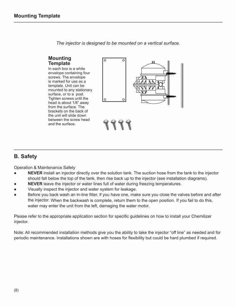
Mounting TemplateIn each box is a white envelope containing four screws. The envelope is marked for use as a template. Unit can be mounted to any stationary surface, or to a post. Tighten screws until the head is about 1/8” away from the surface. The brackets on the back of the unit will slide down between the screw head and the surface.
The injector is designed to be mounted on a vertical surface.
Mounting Template
(8)
A
D
B
E L
MI
J
F
H
GK N
C
O
P
Q
C. C3P
If you’ve purchased a C3P Portable Sprayer installation is unnecessary, but some assembly is required.
The C3P can be used in most Animal Health, Horticulture, Landscaping or general sanitizing applications.
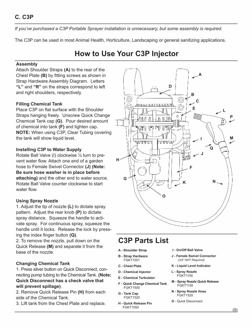
How to Use Your C3P InjectorAssemblyAttach Shoulder Straps (A) to the rear of the Chest Plate (B) by fitting screws as shown in Strap Hardware Assembly Diagram. Letters “L” and “R” on the straps correspond to left and right shoulders, respectively.
Filling Chemical TankPlace C3P on flat surface with the Shoulder Straps hanging freely. Unscrew Quick Change Chemical Tank cap (G). Pour desired amount of chemical into tank (F) and tighten cap. NOTE: When using C3P, Clear Tubing covering the tank will show liquid level.
Installing C3P to Water SupplyRotate Ball Valve (I) clockwise ¼ turn to pre-vent water flow. Attach one end of a garden hose to Female Swivel Connector (J) (Note: Be sure hose washer is in place before attaching) and the other end to water source. Rotate Ball Valve counter clockwise to start water flow.
Using Spray Nozzle1. Adjust the tip of nozzle (L) to dictate spray pattern. Adjust the rear knob (P) to dictate spray distance. Squeeze the handle to acti-vate spray. For continuous spray, squeeze the handle until it locks. Release the lock by press-ing the index finger button (Q).2. To remove the nozzle, pull down on the Quick Release (M) and separate it from the base of the nozzle. Changing Chemical Tank1. Press silver button on Quick Disconnect, con-necting pump tubing to the Chemical Tank. (Note: Quick Disconnect has a check valve that will prevent spillage).2. Remove Quick Release Pin (H) from each side of the Chemical Tank.3. Lift tank from the Chest Plate and replace.
A - Shoulder Strap
B - Strap Hardware FGKT1001
C - Chest Plate
D - Chemical Injector
E - Chemical Turbulator
F - Quick Change Chemical Tank FGKT1500
G - Tank Cap FGKT1520
H - Quick Release Pin FGKT1050
C3P Parts List I - On/Off Ball Valve
J - Female Swivel Connector (3/4” NHT Required)
K - Liquid Level Indicator
L - Spray Nozzle FGKT1100
M - Spray Nozzle Quick Release FGKT1150
N - Spray Nozzle Hose FGKT1520
O - Quick Disconnect
(9)
The following are the basic installation methods for the injectors. Please refer to the application-specific sections for additional information and specific recommendations for that application.
D. HN55 Basic Installation
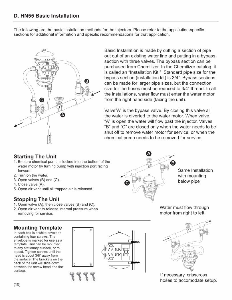
If necessary, crisscross hoses to accomodate setup.
Water must flow through motor from right to left.
Same Installation with mounting below pipe
Starting The Unit1. Be sure chemical pump is locked into the bottom of the water motor by turning pump with injection port facing forward.2. Turn on the water.3. Open valves (B) and (C).4. Close valve (A).5. Open air vent until all trapped air is released.
Stopping The Unit1. Open valve (A), then close valves (B) and (C).2. Open air vent to release internal pressure when removing for service.
Basic Installation is made by cutting a section of pipe out out of an existing water line and putting in a bypass section with three valves. The bypass section can be purchased from Chemilizer. In the Chemilizer catalog, it is called an “Installation Kit.” Standard pipe size for the bypass section (installation kit) is 3/4”. Bypass sections can be made for larger pipe sizes, but the connection size for the hoses must be reduced to 3/4” thread. In all the installations, water flow must enter the water motor from the right hand side (facing the unit).
Valve”A” is the bypass valve. By closing this valve all the water is diverted to the water motor. When valve “A” is open the water will flow past the injector. Valves “B” and “C” are closed only when the water needs to be shut off to remove water motor for service, or when the chemical pump needs to be removed for service.
Mounting TemplateIn each box is a white envelope containing four screws. The envelope is marked for use as a template. Unit can be mounted to any stationary surface, or to a post. Tighten screws until the head is about 3/8” away from the surface. The brackets on the back of the unit will slide down between the screw head and the surface.
B
C
A
B
C
A
(10)
Optional Installations
Do Not RemoveWhile Pressurized
MADEIN THEUSA
PRESSURENOT TOEXCEED
80 P.S.I.. . .
Do Not RemoveWhile Pressurized
MADEIN THEUSA
PRESSURENOT TOEXCEED
80 P.S.I.. . .
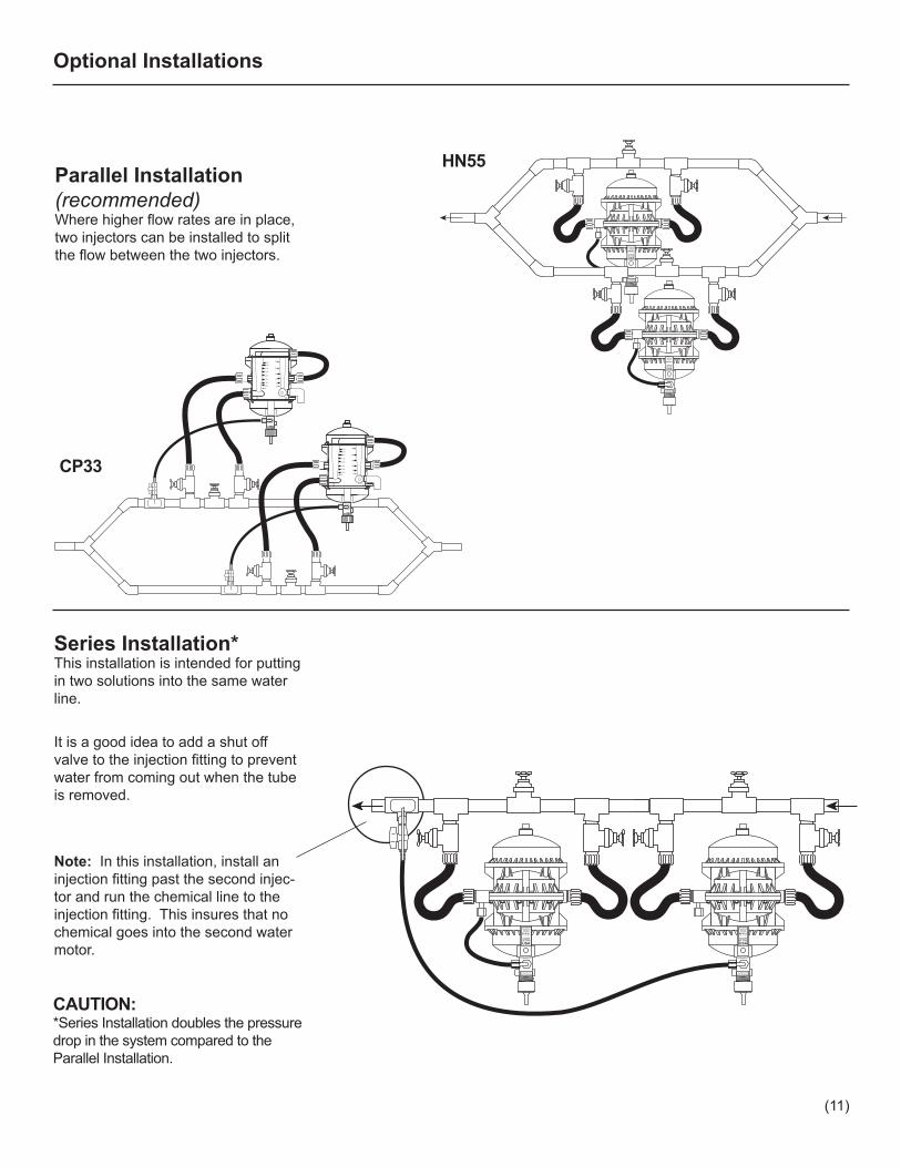
Parallel Installation (recommended)Where higher flow rates are in place, two injectors can be installed to split the flow between the two injectors.
Series Installation* This installation is intended for putting in two solutions into the same water line.
It is a good idea to add a shut off valve to the injection fitting to prevent water from coming out when the tube is removed.
Note: In this installation, install an injection fitting past the second injec-tor and run the chemical line to the injection fitting. This insures that no chemical goes into the second water motor.
Do Not RemoveWhile Pressurized
MADEIN THEUSA
PRESSURENOT TOEXCEED
80 P.S.I.. . .
Do Not RemoveWhile Pressurized
MADEIN THEUSA
PRESSURENOT TOEXCEED
80 P.S.I.. . .
CAUTION:*Series Installation doubles the pressure drop in the system compared to the Parallel Installation.
306.00
5.00
4.00
3.00
2.00
1.50
1.00
0.50
0
24
18
12
6
0
306.00
5.00
4.00
3.00
2.00
1.50
1.00
0.50
0
24
18
12
6
0CP33
HN55
(11)
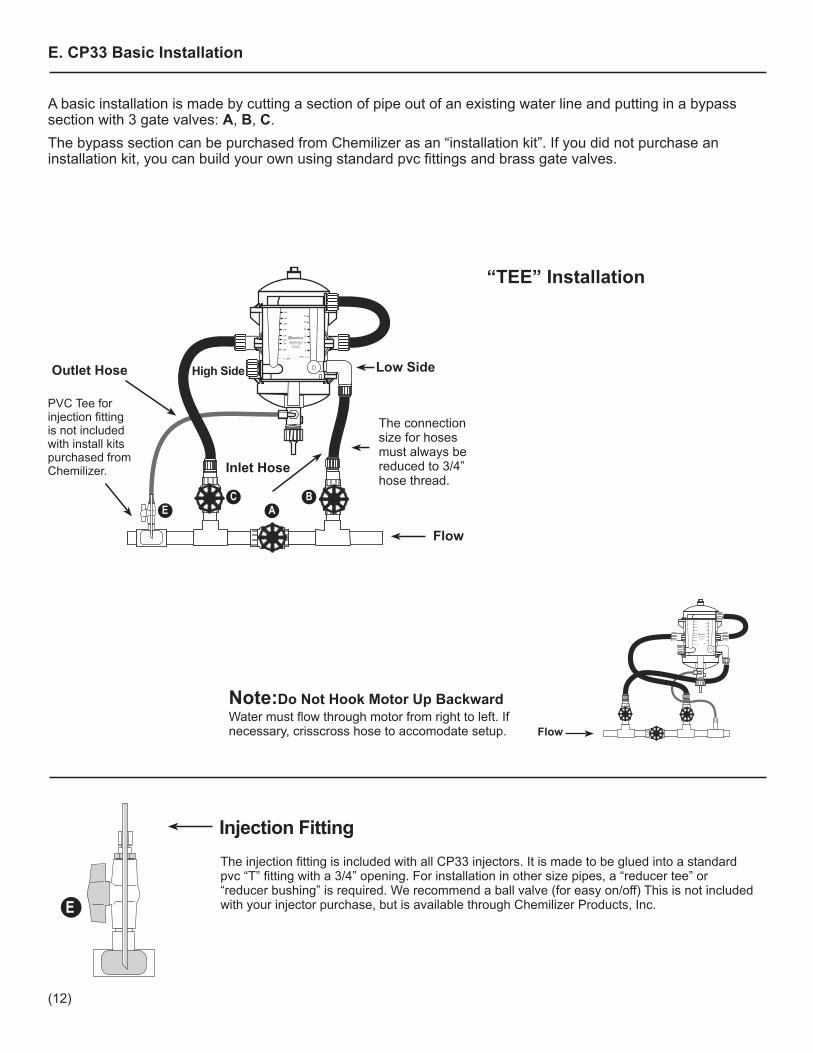
E. CP33 Basic Installation
3.00
0 GPHOPH
1.00
0.50
2.00
1.50
0
6
12
18
4.00
5.00
6.00
24
30
36
CALIBRATED FOR 2:100 PUMP RATIO
EC B
A
The connection size for hoses must always be reduced to 3/4” hose thread.
PVC Tee for injection fitting is not included with install kits purchased from Chemilizer.
Flow
High Side
Inlet Hose
Outlet Hose Low Side
E
Injection FittingThe injection fitting is included with all CP33 injectors. It is made to be glued into a standard pvc “T” fitting with a 3/4” opening. For installation in other size pipes, a “reducer tee” or “reducer bushing” is required. We recommend a ball valve (for easy on/off) This is not included with your injector purchase, but is available through Chemilizer Products, Inc.
A basic installation is made by cutting a section of pipe out of an existing water line and putting in a bypass section with 3 gate valves: A, B, C.The bypass section can be purchased from Chemilizer as an “installation kit”. If you did not purchase an installation kit, you can build your own using standard pvc fittings and brass gate valves.
Note:Do Not Hook Motor Up BackwardWater must flow through motor from right to left. If necessary, crisscross hose to accomodate setup.
3.00
0 GPHOPH
1.00
0.50
2.00
1.50
0
6
12
18
4.00
5.00
6.00
24
30
36
CALIBRATED FOR 2:100 PUMP RATIO
Flow
“TEE” Installation
(12)

1. Locate the inlet gate valve (B), outlet gate valve (C), low volume adjustment valve (D) and control valve (A) in the diagram below.2. Connect water inlet hose at valve (B) to the desired side of your Injection Control Panel and water outlet, left side of water motor to valve C.3. With your system water flow at its maximum, valve (A) is fully open.4. Slowly close valve (A) until float is positioned just above your desired injection setting. Note: Bounce of the float can be a normal condition, the Injection Control Panel setting is read at the high point of the bounce at top of ball.5. If the inlet hose is connected to the low volume (ounces per hour) side of the Injection Control Panel, use the low volume adjustment valve (D) to move the float to the exact setting you want.6. If the inlet hose is connected to the high volume (gallons per hour) side of the Injection Control Panel, use the inlet control valve (B) to move the float to the setting you want.Remember, the float may bounce and the position of the top of the float at the highest point of the bounce is the flow rate the Injection Control Panel will achieve.
Setting the Injection Control Panel
SOLUTIONCONTAINER
WATER FLOW
PUMP
FILTER
306.00
5.00
4.00
3.00
2.00
1.50
1.00
0.50
0
24
18
12
6
0
PVC Tee for injection fitting is not included with install kits purchased from Chemilizer.
FlowFlow Flow
C B
A
Injection Hose
Suction HoseHigh Side
Inlet Hose
E
D
Low Volume Adjustment
Valve
High Volume Adjustment
Valve
(13)
SOLUTIONCONTAINER
3.00
0 GPHOPH
1.00
0.50
2.00
1.50
0
6
12
18
4.00
5.00
6.00
24
30
36
CALIBRATED FOR 2:100 PUMP RATIO
WATER FLOW
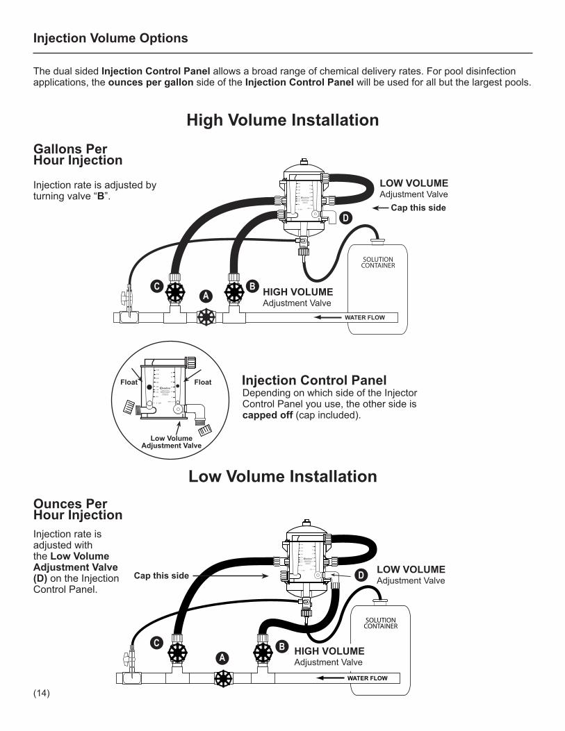
The dual sided Injection Control Panel allows a broad range of chemical delivery rates. For pool disinfection applications, the ounces per gallon side of the Injection Control Panel will be used for all but the largest pools.
Low Volume Installation
Depending on which side of the Injector Control Panel you use, the other side is capped off (cap included).
Injection Control Panel 3.00
0 GPHOPH
1.00
0.50
2.00
1.50
0
6
12
18
4.00
5.00
6.00
24
30
36
CALIBRATED FOR 2:100 PUMP RATIO
Low Volume Adjustment Valve
FloatFloat
Injection Volume Options
High Volume InstallationGallons Per Hour Injection
Injection rate is adjusted with the Low Volume Adjustment Valve (D) on the Injection Control Panel.
Cap this side
ABC
HIGH VOLUME Adjustment Valve
D LOW VOLUME Adjustment Valve
Ounces Per Hour Injection
SOLUTIONCONTAINER
WATER FLOW
3.00
0 GPHOPH
1.00
0.50
2.00
1.50
0
6
12
18
4.00
5.00
6.00
24
30
36
CALIBRATED FOR 2:100 PUMP RATIO
Cap this side
ABC
D
LOW VOLUME Adjustment Valve
Injection rate is adjusted by turning valve “B”.
HIGH VOLUME Adjustment Valve
(14)
F. Application Specific Installation Guidelines
Animal-Health (basic HN55 installation diagram, page 10)
Use the Chemilizer injector for reliable delivery of dietary and medicinal additives into your livestock drinker systems or disinfection of the drinking water.Follow the “Basic” installation method for the model you’ve purchased.Chemilizer injectors can also be mounted on carts for mobile sanitizing applications.
Horticulture (basic HN55 installation diagram, page 10 / basic CP33 installation diagram, page 12)
Whether you use overhead spray booms, spray heads, drip or micro irrigation, Chemilizer injectors integrate easily into your system. They can also be mounted on carts for spot treatment. Follow the “Basic” installation method for the model you’ve purchased.Chemilizer injectors can also be mounted on carts for mobile applications.
Landscaping (basic HN55 installation diagram, page 10 / basic CP33 installation diagram, page 12)
The accuracy and simple operation of the CP33 makes it easy to achieve the proper coverage during continuous fertigation. Many fertilizers are “injector ready” requiring no dilution prior to injection making it even simpler. Because the CP33 is adjustable, multiple models are not needed to apply different fertilizers. The CP33 can accommodate:
• Zone flow rates from 12 GPM to 1000 GPM and above to handle everything from drip irrigation to municipal parks and sports fields • Virtually any make of liquid fertilizer without dilution including micro-nutrients and thick, “lumpy” organics, such as fish hydrolysate and seaweed without clogging • The use of compost tea without damaging the fungi present and degrading the effectiveness of the tea • Easy adjustment of injection rate when changing fertilizers or regulating turf growth • Wide ranges of pH
Water Treatment - Municipal (HN55/CP33 well installation diagram, page 16)
The CP33 is a cost effective alternative for chlorination in treatment facilities serving populations from 100 to several thousand people. It is a safe alternative to gas chlorination.Use the “Basic” installation for the CP33, with the water flowing through the High Side of the Injection control panel (See High Volume Installation diagram, page 14).
Swimming Pools (HN55/CP33 pool installation diagram, page 17-19)
Chemilizer injectors provide reliable, accurate injection resulting in less chemical waste and reduced cost as well as a tightly controlled level of chlorine and pH.
(15)

INSTALLATION PROCEDURE
Installation Diagrams - Water Treatment Residential / Community WellsChemilizer injectors easily deliver cost-effective, easily obtained chemicals such as chlorine, to effectively sanitize drinking water.
PRESSURE TANK
CHEMICALCONTAINER
CHEMICALHOSE
306.00
5.00
4.00
3.00
2.00
1.50
1.00
0.50
0
24
18
12
6
0
PUMP
CP33 CHEMICALINJECTOR
PUMP
PRESSURE TANK
CHEMICALCONTAINER
306.00
5.00
4.00
3.00
2.00
1.50
1.00
0.50
0
24
18
12
6
0
PRESSURE SWITCH
PRESSURE SWITCH
CONTACTTANK
HOLDINGTANK
CHEMICALCONTAINER
HOLDINGTANK
HN55CHEMICALINJECTOR
WELL
PUMP
CHEMICALCONTAINER
PRESSURETANK
PRESSURE SWITCH
PRESSURE SWITCH
- HN55 Well Installation Diagram
- CP33 Well Installation Diagram
HN55
CP33
(16)
Chemilizer injectors provide reliable, accurate injection resulting in less chemical waste and reduced cost as well as a tightly controlled level of chlorine and pH.
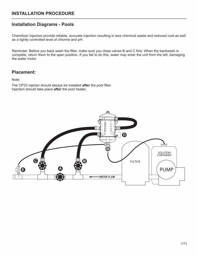
Reminder: Before you back wash the filter, make sure you close valves B and C first. When the backwash is complete, return them to the open position. If you fail to do this, water may enter the unit from the left, damaging the water motor.
SOLUTIONCONTAINER
WATER FLOW
PUMP
FILTER
306.00
5.00
4.00
3.00
2.00
1.50
1.00
0.50
0
24
18
12
6
0
BC
AE
D
Placement:
INSTALLATION PROCEDURE
Installation Diagrams - Pools
Note: The CP33 injector should always be installed after the pool filter. Injection should take place after the pool heater.
(17)

INSTALLATION PROCEDURE
Installation Diagrams - Pools
- Electric Controller Diagram #1
ORP
pH
NormallyClosed
Solenoid
NormallyClosed
SolenoidACIDCHLORINE
306.00
5.00
4.00
3.00
2.00
1.50
1.00
0.50
0
24
18
12
6
0
306.00
5.00
4.00
3.00
2.00
1.50
1.00
0.50
0
24
18
12
6
0
Chemilizer Chemilizer
current
Installation without Salt Chlorine Generator
(18)
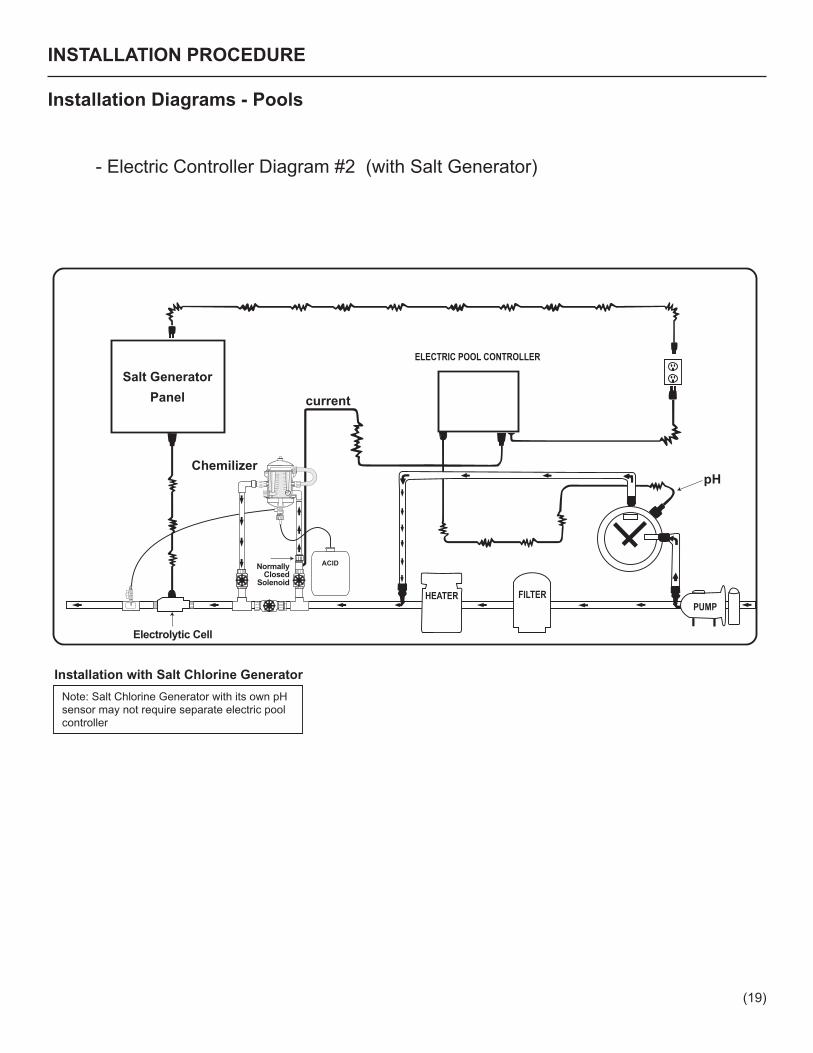
INSTALLATION PROCEDURE
Installation Diagrams - Pools
- Electric Controller Diagram #2 (with Salt Generator)
Salt Generator
Panel
Note: Salt Chlorine Generator with its own pH sensor may not require separate electric pool controller
current
Chemilizer30
6.00
5.00
4.00
3.00
2.00
1.50
1.00
0.50
0
24
18
12
6
0
pH
Installation with Salt Chlorine Generator
Electrolytic Cell
NormallyClosed
Solenoid
ACID
(19)

(20)
WORKSHEETSHN55 Dilution for Water Treatment
Selection of the pump ratio will determine how long the stock solution lasts (2:128 will cause stock solution to run out quicker than 1:128): Injection factor Using 2:128 is .0156 Using 1:128 is .0078 Using 1:100 is .01 Using 2:100 is .02 Using 1:250 is .004 Using 1:500 is .0025 Required Dilution:
% chlorine X Injection factor X 1,000,000 then subtract 1 = gallons of water to mix with 1 gal. of chlorine Total Chlorine Demand PPM
# of Days chlorine solution will last
GPD of water use X Injection factor = GPD of chlorine solution used 128
GPD of solution = # of days between refillsSize of solution container in gallons
Examples: A well supplying 400 gal. of water per day (4 people, 100 gal. each) with least frequent refill.
Dilution using 5.25% chlorine (household bleach) and a 1:250 pump
5.25 % X .004 X 1,000,000 = 4.14 – 1 = 3.14 gal. of water to 1 gal. chlorine 50.7 PPM
Time between refills with a 25 gal. solution tank
400 X .004 = 1.6 GPD, then divide 25 by 1.6 to get approximately 15.5 days to empty the tank
Dilution using 12% chlorine and a 2:128 pump
12 % X .0156 X 1,000,000 = 12.4 – 1 = 11.4 gal. of water to 1 gal. chlorine 151 PPM
Time between refills with a 35 gal. solution tank
400 X .0156 = 6.24 GPD, then divide 35 by 6.24 to get approximately 5.5 days to empty the tank.
3.0 PPM IRON X .9 = 2.7 PPM5.0 PPM H2S X 8.5 = 42.5 PPMALGAE = 5.0 PPMDESIRED RESIDUAL = 0.5 PPMChlorine Demand = 50.7 PPM
20.0 PPM IRON X .9 = 18 PPM15.0 PPM H2S X 8.5 = 127.5 PPM ALGAE = 5.0 PPMDESIRED RESIDUAL = 0.5 PPMChlorine Demand = 151 PPM
CHLORINE DEMAND CALCULATION:IRON ________PPM X .9 = _____PPM
HYDROGEN SULFIDE ________PPM X 8.5 = _____PPMALGAE REQUIRES EXTRA 5 PPM = _____PPM
DESIRED RESIDUAL= _____PPMTOTAL CHLORINE DEMAND = _____PPM
5. How to Determine Your Chemical MixIf you are using the HN55 for Water Treatment, use the worksheet below:

(21)
WORKSHEETSCP33 Injection Rate Setting
Dry Calculation
% of chemical concentration ______ The % of chemical concentration is the % A in the injection solution.Bag weight in lbs. ______ BMax. solubility/gal. in ounces ______ The maximum solubility is on the fertilizer C or chemical label or bag.PPM desired ______ DWater flow in GPM ______ The water flow entered should be the E highest rate of flow the system can attain.
Divide C by 16 and then divide B by the result, which X is the number of gallons of water to mix with the chemical. ______ X
Divide C by 128 and multiply the result by A, which Y is the concentration after mixing with water volume X. ______ YDivide D by 1,000,000 = ______ FMultiply E by 60 = ______ GMultiply F by G = ______ HDivide H by Y = ______ Gallon per hour setting for the CP33. I If you wish to set the CP33 using the ounces scale on the injection control panel, multiply I by 128. ______
Liquid Calculation
% of chemical concentration ______ The % of chemical concentration is the % A in the injection solution.PPM desired ______ BWater flow in GPM ______ The water flow entered should be the C highest rate of flow the system can attain.Divide B by 1,000,000 = ______ DMultiply C by 60 = ______ EMultiply D by E = ______ FDivide F by A = ______ Gallon per hour setting for the CP33. G
If you wish to set the CP33 using the ounces side of the injection control panel, multiply G by 128. _______
Disclaimer: This worksheet is for determining the proper injection rate setting on the CP33 based on the desired PPM in the output water flow and is provided as an aid for the convenience of our users. The results should not be solely relied upon to determine the setting for the injection rate in your application. Measuring the PPM in the output water is strongly recommended. Chemilizer accepts no liability for any damages incurred as a result of using this worksheet.
Notes:
1. If the result of the calculation exceeds 6 gallons per hour, you have two choices. First, if there is a more concentrated form of the chemical being used, rerun the calculations with that data. If not, it will require multiple CP33 units to meet the volume of injection. Call Chemilizer to discuss the best configuration to meet your needs.
2. When using a dry chemical, the higher the solubility the higher the PPM you can achieve with a single CP33.
If you are using the CP33, use the worksheet below:
CHEMICALCONTAINER
PRESSURETANK
WELL
PUMPBC
A
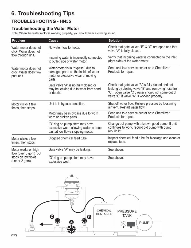
TROUBLESHOOTING - HN55Troubleshooting the Water MotorNote: When the water motor is working properly, you should hear a clicking sound.
Problem Cause Solution
Water motor does not click. Water does not flow through unit.
No water flow to motor. Check that gate valves “B” & “C” are open and that valve “A” is fully closed..
Incoming water is incorrectly connected to outlet side of water motor.
Verify that incoming water is connected to the inlet (right side) of the water motor.
Water motor does not click. Water does flow past unit.
Water-motor is in “bypass” due to damaged parts on the inside of water motor or excessive wear of moving parts.
Send unit to a service center or to Chemilizer Products for repair.
Gate valve “A” is not fully closed or may be leaking due to wear from sand or debris.
Check that gate valve “A” is fully closed and not leaking by closing valve “B” and removing hose from “C”, open valve “C”, water should not come out of valve “C” if valve “A” is working properly.
Motor clicks a few times, then stops.
Motor may be in bypass due to worn worn or broken parts.
Send unit to a service center or to Chemilizer Products for repair.
“O” ring on pump stem may have excessive wear, allowing water to seep past at low flows stopping motor.
Change out pump with a known good pump. If unit continues to work, rebuild old pump with pump rebuild kit.
Motor works on high flow (over 5 gpm) but stops on low flows (under 2 gpm).
Gate valve “A” may be leaking.
“O” ring on pump stem may have excessive wear.
See above.
See above.
Unit is in bypass condition. Shut off water flow. Relieve pressure by loosening air vent. Restart water flow.
Motor clicks a few times, then stops.
Clogged chemical feed tube. Inspect chemical feed tube for blockage and clean or replace tube.
6. Troubleshooting Tips
(22)
PUMP
PRESSURE TANK
CHEMICALCONTAINER
306.00
5.00
4.00
3.00
2.00
1.50
1.00
0.50
0
24
18
12
6
0
BC
A
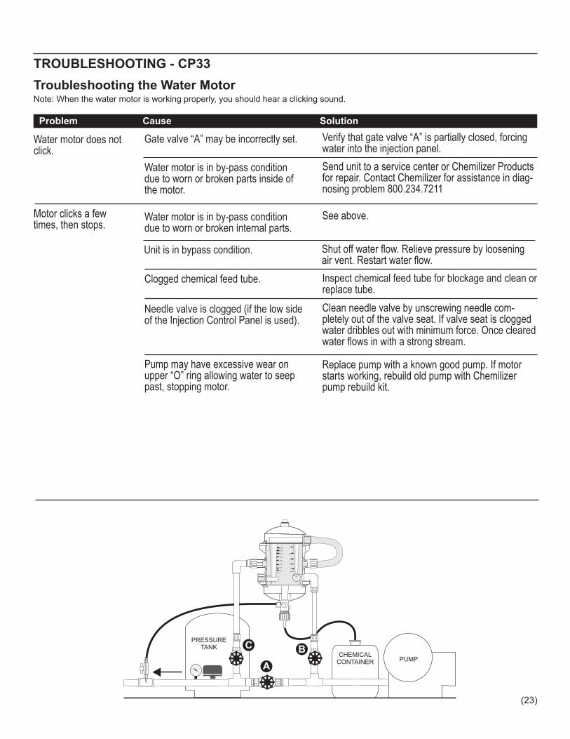
Troubleshooting the Water MotorNote: When the water motor is working properly, you should hear a clicking sound.
Problem Cause Solution
TROUBLESHOOTING - CP33
Water motor does not click.
Gate valve “A” may be incorrectly set. Verify that gate valve “A” is partially closed, forcing water into the injection panel.
Water motor is in by-pass condition due to worn or broken parts inside of the motor.
Send unit to a service center or Chemilizer Products for repair. Contact Chemilizer for assistance in diag-nosing problem 800.234.7211
Water motor is in by-pass condition due to worn or broken internal parts.
See above.Motor clicks a few times, then stops.
Clogged chemical feed tube. Inspect chemical feed tube for blockage and clean or replace tube.
Needle valve is clogged (if the low side of the Injection Control Panel is used).
Clean needle valve by unscrewing needle com-pletely out of the valve seat. If valve seat is clogged water dribbles out with minimum force. Once cleared water flows in with a strong stream.
Pump may have excessive wear on upper “O” ring allowing water to seep past, stopping motor.
Replace pump with a known good pump. If motor starts working, rebuild old pump with Chemilizer pump rebuild kit.
Unit is in bypass condition. Shut off water flow. Relieve pressure by loosening air vent. Restart water flow.
(23)
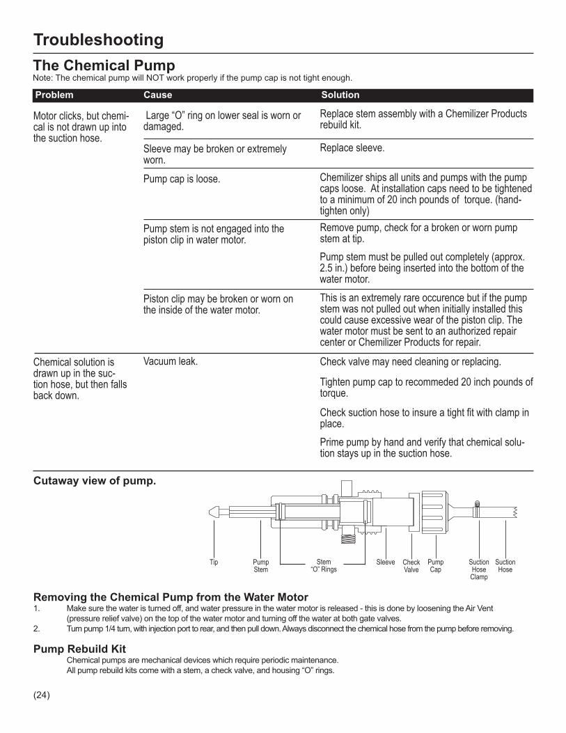
Suction Hose
Suction HoseClamp
PumpCap
CheckValve
PumpStem
Stem“O” Rings
SleeveTip
Cutaway view of pump.
Removing the Chemical Pump from the Water Motor1. Make sure the water is turned off, and water pressure in the water motor is released - this is done by loosening the Air Vent (pressure relief valve) on the top of the water motor and turning off the water at both gate valves.2. Turn pump 1/4 turn, with injection port to rear, and then pull down. Always disconnect the chemical hose from the pump before removing.
Pump Rebuild Kit Chemical pumps are mechanical devices which require periodic maintenance. All pump rebuild kits come with a stem, a check valve, and housing “O” rings.
The Chemical PumpNote: The chemical pump will NOT work properly if the pump cap is not tight enough.
Troubleshooting
Motor clicks, but chemi-cal is not drawn up into the suction hose.
Sleeve may be broken or extremely worn.
Replace sleeve.
Pump cap is loose. Chemilizer ships all units and pumps with the pump caps loose. At installation caps need to be tightened to a minimum of 20 inch pounds of torque. (hand-tighten only)
Pump stem is not engaged into the piston clip in water motor.
Remove pump, check for a broken or worn pump stem at tip.
Piston clip may be broken or worn on the inside of the water motor.
This is an extremely rare occurence but if the pump stem was not pulled out when initially installed this could cause excessive wear of the piston clip. The water motor must be sent to an authorized repair center or Chemilizer Products for repair.
Large “O” ring on lower seal is worn or damaged.
Replace stem assembly with a Chemilizer Products rebuild kit.
Problem Cause Solution
Pump stem must be pulled out completely (approx. 2.5 in.) before being inserted into the bottom of the water motor.
Vacuum leak. Check valve may need cleaning or replacing.Chemical solution is drawn up in the suc-tion hose, but then falls back down.
Tighten pump cap to recommeded 20 inch pounds of torque.
Check suction hose to insure a tight fit with clamp in place.Prime pump by hand and verify that chemical solu-tion stays up in the suction hose.
(24)

Troubleshooting
The Injection Control Panel
If the Injection Control Panel low volume float has sunk to the bottom of the Injection Control Panel (when pool pump is on), the Low Volume Adjustment Valve may be clogged from debris that was not trapped by the filter. This can only occur when using the low volume side of the Injection Control Panel (the right side).
1. Turn off pump or other water source.2. Remove the Low Volume Adjustment Valve control knob from the Injection Control Panel, by unscrewing it. 3. Turn pump/water source on until water spurts from the open needle valve, in a steady stream clearing the debris. 4. Turn off the pump/water source and replace the needle valve. 5. Repeat the steps for initially setting the injection level.
(25)

7. Maintenance Tips
Water Motor1. Do not let the unit freeze. 2. Periodically replace the chemical hose and connectors. Chemical buildup will cause the unit not to pump. 3. If the chemical pump becomes hard to remove from the bottom of water motor, clean the inside of the opening on the bottom cap of the water motor with a toothbrush & white vinegar.
Chemical Pump1. Always use the pump designed for your application (i.e. when pumping vinegar, use a vinegar pump.) 2. Clean the pump after use by running 5 gallons of clean water through the pump, or by removing the pump and hand cleaning individual parts.
Injection Control Panel (CP33 Only)1. Over tightening the needle valve will cause damage or failure of the valve. 2. Should the needle valve become clogged, remove the valve to allow blockage to move through with water flow. 3. Should clogging of the injection control panel become a problem, install a hose end screen.
Chemical Tank (C3P Only)1. Keep the chemical tank clean of foreign particles and trash. 2. Do not stand the C3P on its end, as this may damage the elbows attached to the Chemical Tank.
Other1. Water is always a factor with the life of any injector. If you know you have problem water, an in-line filter before the injector is a wise investment. 2. Keep your stock solution container clean of foreign particles and trash. 3. Keep the suction hose filter off the bottom of the stock solution bucket, insoluble particles may cause clogging.
Chemical Notice:The Chemilizer injector is a general purpose injector; it was not designed to inject acid. However, some customers use it to inject acids of varying concentrations because our design limits the “damage” caused by aggressive chemicals to the pump, which is inexpensive to repair or replace. Our pump is resistant to chemicals of varying concentrations and a wide range of pH. However, more corrosive chemicals will degrade pump parts faster, necessitating frequent repair or replace-ment, adding a negligible amount to the cost of using our injectors with that chemical or group of chemicals. Pump life is determined by a number of factors that include duty cycle, chemical(s) being injected, and frequency of clean-ing, among others. Therefore each customer’s experience will be different. Normally the check valve, the pump stem and stem o-rings degrade first with the ceramic sleeve taking longer to be affected. Therefore, a pump rebuild kit will be the most frequent maintenance for customers using aggressive chemicals.
(26)

8. Frequently Asked QuestionsHow accurate is your unit?Answer: Chemilizer’s injectors are very accurate due to superior product design and our stringent quality assurance methods. And they maintain their accuracy longer because there are fewer wear points than with traditional designs. Why should I buy Chemilizer over competitive units?Answer: A Chemilizer unit provides you with a number of advantages not available from our competitors. These advan-tages include superior quality backed by a 2 year, warranty (unique in the industry); avoid dependence on an unreliable or expensive electrical source; increased product longevity due to the fact the water motor is not subject to chemical attack; and, last but not least, lower total cost of ownership resulting from reasonable repair cost, instead of replacement. Do you work on low flow?Answer: Chemilizer’s CP33 and HN55 are versatile. The HN55 can operate with as little as 1 gph and as high as 12 gpm. Whereas the CP33 can operate with as little as 12 gpm and can handle virtually any flow rate above 12 gpm. Do you have something bigger (than the HN55)?Answer: Yes, if you need a flow rate above 12 GPM, our CP33 metered chemical injector can handle virtually any flow rate above 5 GPM, injecting from 1 OZ. per hour up to 6 GAL. per hour. If you want proportional injection, two HN55’s can be mounted in parallel to handle 24 GPM. Is it non-electric?Answer: Our non-electric water motor functions on demand with water flow. Inside the water motor is a fixed diaphragm assembly that travels up and down. This in turn causes the pump, located in the bottom of the motor, to function. The chemical solution is drawn through the pump, an inexpensive replacement part, but never enters the water motor, thereby extending the life of the water motor. Where are your products made?Answer: The units are designed, assembled and tested at our facility in Largo, FL. How easy is it to install?Answer: Chemilizer’s injectors are very easy to install. Since all Chemilizer injectors are non-electric, installation consists of simply attaching the chemical injector to your existing water source. To make things even easier Chemilizer also offers optional installation kits. Installation can often be accomplished in under an hour. How do I setup the injection control panel?Answer: To set up the injection control panel simply connect your water supply to either the low flow side (OPH) or the high flow side (GPH) of the injection control panel. Then simply adjust either the needle valve to alter your Ounces Per Hour reading or adjust your gate valve to alter your Gallons Per Hour reading until the flow meter reflects the injection rate you wish to maintain. How long will the unit last?Answer: Chemilizer’s chemical injectors are built to last. That is why we can offer a 2 year warranty on our water motor. While, your results will depend on your application and duty cycle, many of our customers report their units last 5 years or more with simple, cost effective maintenance. Our satisfied customers have reported using our unit for over 10 years with only minor repairs. Why is your motor better than the piston type?Answer: Chemilizer injectors are better because with our diaphragm design, there is no piston to cause wear or be replaced. Our motor does not need pre-filtration and is unaffected by chemical you are using. This saves you time and money. And adds peace of mind.
Can you mount the unit on a cart?Answer: Yes, Chemilizer’s chemical injectors can be mounted almost anywhere and in any orientation. What type of chemicals can you pump?Answer: Our products have been proven pumping Chlorine, Surfactants, pH controllers, Fertilizers, Degreasers, Lu-bricants, Coolants, Biocides, Germicides, Nutrients, Pharmaceuticals, materials such as tetracycline or amoxicillin, and viscous materials as thick asas honey. If you have a question concerning a specific chemical send us an email at:[email protected] or call us at 1-800-234-7211. (27)
Can I use your injector to inject acid(s)?Answer: Although, we have tested some kinds of acid successfully, we do not recommend the use or our injectors to inject acid. We have been successful pumping a 95% sulfuric acid in our facility. However, weaker acid solutions, i.e. 65% sulfuric acid, may accelerate chemical pump failure simply because they are more caustic.
We do not recommend using our injector for acid injection due to the wide range of acids available and the risk of improp-er handling by your personnel. Depending upon the type of acid you use, the life of the chemical pump may vary widely. Motor failure that is caused or contributed to by injecting acids is not warranted. The warranty would still cover other types of failures.
Acid injectors are very expensive, often costing thousands of dollars. Ours is much more cost effective, but may require more frequent maintenance, if used to inject acid. Can you pump multiple chemicals?Answer: Our units can easily be installed in parallel or in series to inject multiple chemicals in the same water line. This avoids problems that can occur when the wrong chemicals come in contact before entering the water line. Where do you mix your meds?Answer: All Chemilizer units inject chemicals after the water flow leaves the motor, never inside the water motor. Test have shown total mixing of chemical in water occurs just a 18” from the point of injection. Is your pump adjustable?Answer: The CP33 features a injection control panel that allows you to adjust your rate of injection. We offer four pumps with different ratios to meet your needs, these are: a 1:128 pump , a 2:128 pump , a 1:100 pump, and a 2:100 pump. The HN55 chemical pump is a fixed ratio to ensure maximum accuracy at any GPM. By adjusting your chemical solution, you can achieve the desired level of dilution. Is it repairable?Answer: Our unique modular design and minimum number of moving parts, ensure simple, cost effective maintenance. Chemilizer offers a complete line of parts, including rebuild kits for both the water motor and the chemical pump. And repairs are easy. Replacing a chemical pump takes less than a minute and it can be rebuilt, without tools, in less than 5 minutes. Rebuilding the water motor, required very infrequently, can be done in less than an hour. What type of warranty does the unit have?Answer: We stand behind our products 100%. So much so, that each unit ships with a two year warranty on our water motor. The chemical pump, due to the variety of chemicals that can be used, carries no warranty. Instead, it has been designed to be disposable and inexpensive. It can be replaced in less than a minute without tools.
Frequently Asked Questions (continued)
(28)

9. Technical SpecificationsHN55 InjectorWater flow..................... 1GPH - 13GPM / metric .063 lpm (3.78 lph) to 45.4 lpm (2,724 lph)Pressure........................ 2 psi to 80 psi / metric .138 bar to 5.51 barMax. temp...................... 110° F (43.3° C)Pipe size........................ 3/4” nht (national hose thread)Ratio............................... SEE PUMP LABEL*Size................................ 11” height x 8 1/2” width / metric 27.9 cm x 21.6 cmWeight............................ 6 3/4 lbs. (2.5 kg)
Chemical Pump ratio and o-ring material:CH9000- 209 1:128 VitonCH9000- 210 1:100 VitonCH9000- 211 2:100 VitonCH9000- 220 2:128 VitonCH9000- 225 1:250 VitonCH9000- 226 1:500 VitonCH9000- 309 1:128 Silicone (Vinegar injection only)CH9000- 310 1:100 Silicone (Vinegar injection only)CH9000- 311 2:100 Silicone (Vinegar injection only)CH9000- 320 2:128 Silicone (Vinegar injection only)CH9000- 325 1:250 Silicone (Vinegar injection only)
CP33 InjectorWater flow……………….12 GPM to unlimited / metric 46 lpm to unlimitedPressure.........................4 psi to 80 psi / metric .276 bar to 5.51 barMax. temp......................110° F (43.3° C)Pipe size........................ 3/4” nht (national hose thread)Ratio...............................SEE PUMP LABEL*Size................................11” ht x 8 1/2” width / metric 27.9 cm x 21.6 cmWeight............................ 6 3/4 lbs. (2.5 kg)
Chemical Pump ratio and o-ring material:CH6000- 209 1 GPH VitonCH6000- 210 3 GPH VitonCH6000- 211 6 GPH VitonCH6000- 210 M 12 LPH VitonCH6000- 211 M 24 LPH VitonCH6000- 309 1 GPH Silicone (Vinegar injection)CH6000- 310 3 GPH Silicone (Vinegar injection)CH6000- 311 6 GPH Silicone (Vinegar injection)CH6000- 310 M 12 LPH Silicone (Vinegar injection)CH6000- 311 M 24 LPH Silicone (Vinegar injection)
Note: “M” designates Injection Control Panel with metric scale.
C3P Portable SprayerInjection Rate……………1:100 (included)(Availability………………1:500, 1:250, 1:100, 2:100, 1:128, 2:128)Accuracy…………………Plus/minus 5%Pressure…………………2 PSI to 80 PSI, .138 BAR-5.51 BARConnection………………3/4” NHT (National Hose Thread)Size………………………17” (H) x 12” (W) x 10” (depth)Size w/straps……………23” (H) x 12” (W) x 20” (depth)Chemical Tank Capacity...32 ouncesDry Weight………………15 lbs
(29)
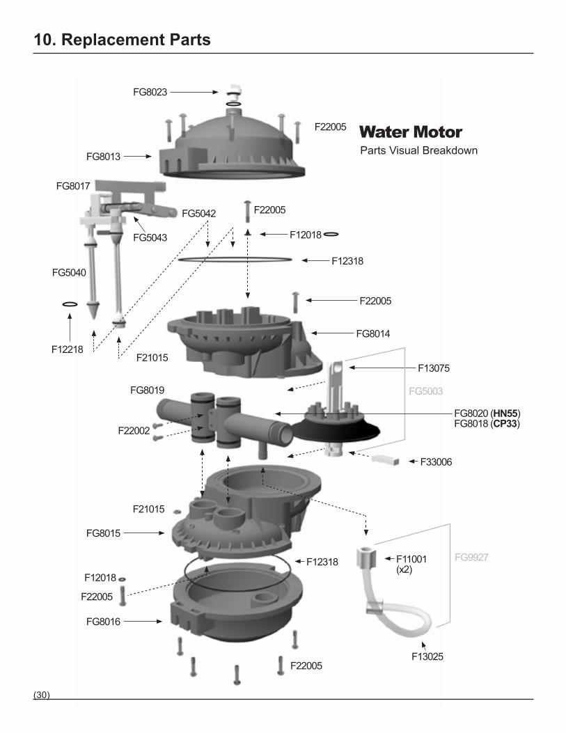
10. Replacement Parts
Parts Visual BreakdownWater Motor
FG8017
FG8013
FG8023
FG5042
FG5043
FG5040
F12018
F22005
F12318
FG8014
F13075
FG5003
FG9927
F33006
F13025
FG8019
FG8020 (HN55)FG8018 (CP33)
F22002
F11001 (x2)
FG8015
FG8016
F12018F12318
F12218
F22005
F22005
F21015
F21015
F22005
F22005
(30)
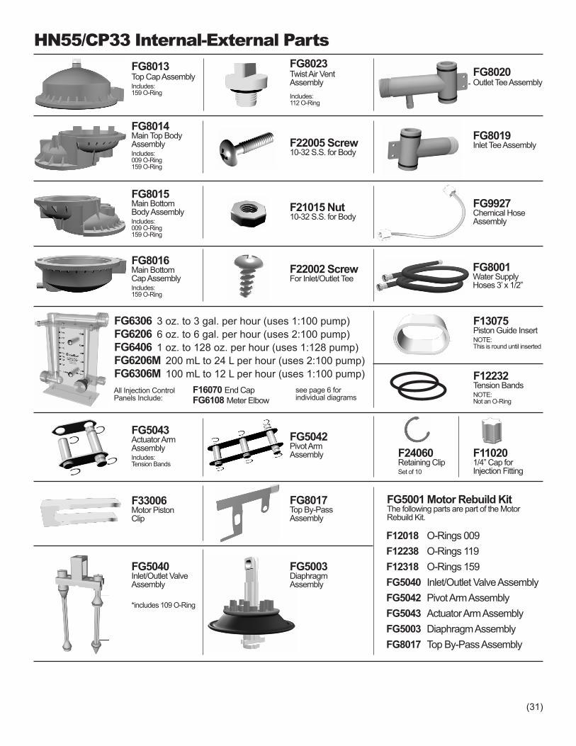
HN55/CP33 Internal-External PartsFG8013Top Cap AssemblyIncludes:159 O-Ring
FG8014Main Top BodyAssemblyIncludes:009 O-Ring159 O-Ring
FG8015Main BottomBody Assembly Includes:009 O-Ring159 O-Ring
FG8016Main BottomCap Assembly Includes:159 O-Ring
FG8023Twist Air VentAssemblyIncludes:112 O-Ring
F21015 Nut10-32 S.S. for Body
F22002 ScrewFor Inlet/Outlet Tee
F22005 Screw10-32 S.S. for Body
FG8020Outlet Tee Assembly
FG8019Inlet Tee Assembly
FG9927Chemical HoseAssembly
FG8001Water SupplyHoses 3’ x 1/2”
FG6306 3 oz. to 3 gal. per hour (uses 1:100 pump)FG6206 6 oz. to 6 gal. per hour (uses 2:100 pump)FG6406 1 oz. to 128 oz. per hour (uses 1:128 pump)FG6206M 200 mL to 24 L per hour (uses 2:100 pump)FG6306M 100 mL to 12 L per hour (uses 1:100 pump)
FG5043Actuator ArmAssembly Includes:Tension Bands
FG5040Inlet/Outlet ValveAssembly
*includes 109 O-Ring
FG5042Pivot ArmAssembly
FG5003DiaphragmAssembly
FG5001 Motor Rebuild KitThe following parts are part of the Motor Rebuild Kit.
F12018 O-Rings 009F12238 O-Rings 119F12318 O-Rings 159FG5040 Inlet/Outlet Valve AssemblyFG5042 Pivot Arm AssemblyFG5043 Actuator Arm AssemblyFG5003 Diaphragm AssemblyFG8017 Top By-Pass Assembly
F33006Motor PistonClip
FG8017Top By-PassAssembly
F13075Piston Guide InsertNOTE:This is round until inserted
F12232Tension BandsNOTE:Not an O-Ring
F110201/4” Cap for Injection Fitting
see page 6 for individual diagrams
All Injection Control Panels Include:
F16070 End CapFG6108 Meter Elbow
F24060Retaining ClipSet of 10
(31)
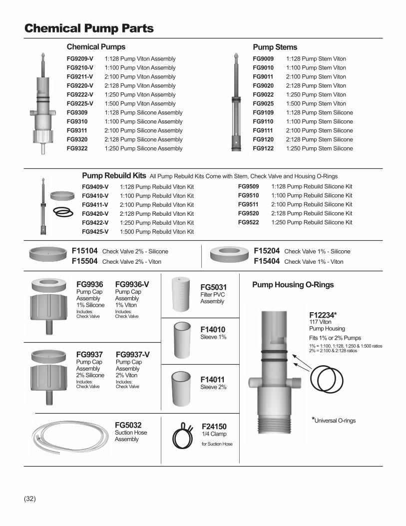
FG9409-V 1:128 Pump Rebuild Viton KitFG9410-V 1:100 Pump Rebuild Viton KitFG9411-V 2:100 Pump Rebuild Viton KitFG9420-V 2:128 Pump Rebuild Viton KitFG9422-V 1:250 Pump Rebuild Viton KitFG9425-V 1:500 Pump Rebuild Viton Kit
Chemical Pump Parts
FG5031Filter PVCAssembly
Chemical PumpsFG9209-V 1:128 Pump Viton AssemblyFG9210-V 1:100 Pump Viton AssemblyFG9211-V 2:100 Pump Viton AssemblyFG9220-V 2:128 Pump Viton AssemblyFG9222-V 1:250 Pump Viton AssemblyFG9225-V 1:500 Pump Viton AssemblyFG9309 1:128 Pump Silicone AssemblyFG9310 1:100 Pump Silicone AssemblyFG9311 2:100 Pump Silicone AssemblyFG9320 2:128 Pump Silicone AssemblyFG9322 1:250 Pump Silicone Assembly
FG9009 1:128 Pump Stem VitonFG9010 1:100 Pump Stem VitonFG9011 2:100 Pump Stem VitonFG9020 2:128 Pump Stem VitonFG9022 1:250 Pump Stem VitonFG9025 1:500 Pump Stem VitonFG9109 1:128 Pump Stem SiliconeFG9110 1:100 Pump Stem SiliconeFG9111 2:100 Pump Stem SiliconeFG9120 2:128 Pump Stem SiliconeFG9122 1:250 Pump Stem Silicone
Pump Stems
Pump Rebuild Kits All Pump Rebuild Kits Come with Stem, Check Valve and Housing O-Rings
FG9509 1:128 Pump Rebuild Silicone KitFG9510 1:100 Pump Rebuild Silicone KitFG9511 2:100 Pump Rebuild Silicone KitFG9520 2:128 Pump Rebuild Silicone KitFG9522 1:250 Pump Rebuild Silicone Kit
F15104 Check Valve 2% - Silicone
F15504 Check Valve 2% - Viton
F15204 Check Valve 1% - Silicone
F15404 Check Valve 1% - Viton
FG9936Pump CapAssembly1% SiliconeIncludes:Check Valve
FG9937Pump CapAssembly2% SiliconeIncludes:Check Valve
FG9936-VPump CapAssembly1% VitonIncludes:Check Valve
FG9937-VPump CapAssembly2% VitonIncludes:Check Valve
F14010Sleeve 1%
F14011Sleeve 2%
FG5032Suction HoseAssembly
F241501/4 Clampfor Suction Hose
F12234*117 VitonPump Housing
Pump Housing O-Rings
Fits 1% or 2% Pumps1% = 1:100, 1:128, 1:250 & 1:500 ratios2% = 2:100 & 2:128 ratios
*Universal O-rings
(32)

1.50
GPHOPH
0.50
0.25
1.00
0.75
00
3
6
9
2.00
2.50
3.00
12
15
18
CALIBRATED FOR 1:100 PUMP RATIO
3.00
0 GPHOPH
1.00
0.50
2.00
1.50
0
6
12
18
4.00
5.00
6.00
24
30
36
CALIBRATED FOR 2:100 PUMP RATIO
6
0 LPHmLH
2
1
4
3
0
100
175
250
8
12
300
400
500
CALIBRATED FOR 1:100 PUMP RATIO
12
0 LPHmLH
4
2
8
6
0
200
350
500
16
24
600
800
1000
CALIBRATED FOR 2:100 PUMP RATIO
OPH0 OPH
0.0
1.0
2.0
3.0
4.0
5.0
6.0
7.0
8.0
32
16
48
64
96
128
CALIBRATED FOR 1:128 PUMP RATIO
Range
CP33 Injection Control Panels for Hourly Volumetric Injection Ranges
O-Rings areShownActualSize
F12318O-Ring159 Buna- Body Cap
F12234O-Ring117 Viton - Pump Housing
F12232NOT AN O-RINGTension Bands
F12218O-Ring109 EP - Inlet/Outlet Valves
F12238O-Ring119 Buna- Inlet/Outlet Tee
F12018O-Ring009 Buna- Main Body
FG6406
3 oz. to 3 gal.per hour
6 oz. to 6 gal.per hour
100 mL to 12 Lper hour
200 mL to 24 Lper hour
1 oz. to 128 oz.per hour
FG6306 FG6206 FG6306M FG6206M
Settings
O-Rings not available for individual sale.
(33)

FGKT1520Tank Cap
FGKT1500Tank
FGKT1200Spray Nozzle Hose
FGKT1100Spray Nozzle
FGKT1150Spray Nozzle Quick Release
FGKT1050Tank Quick Release Pins
FGKT1001Strap Harware
C3P Replacement Parts
(34)
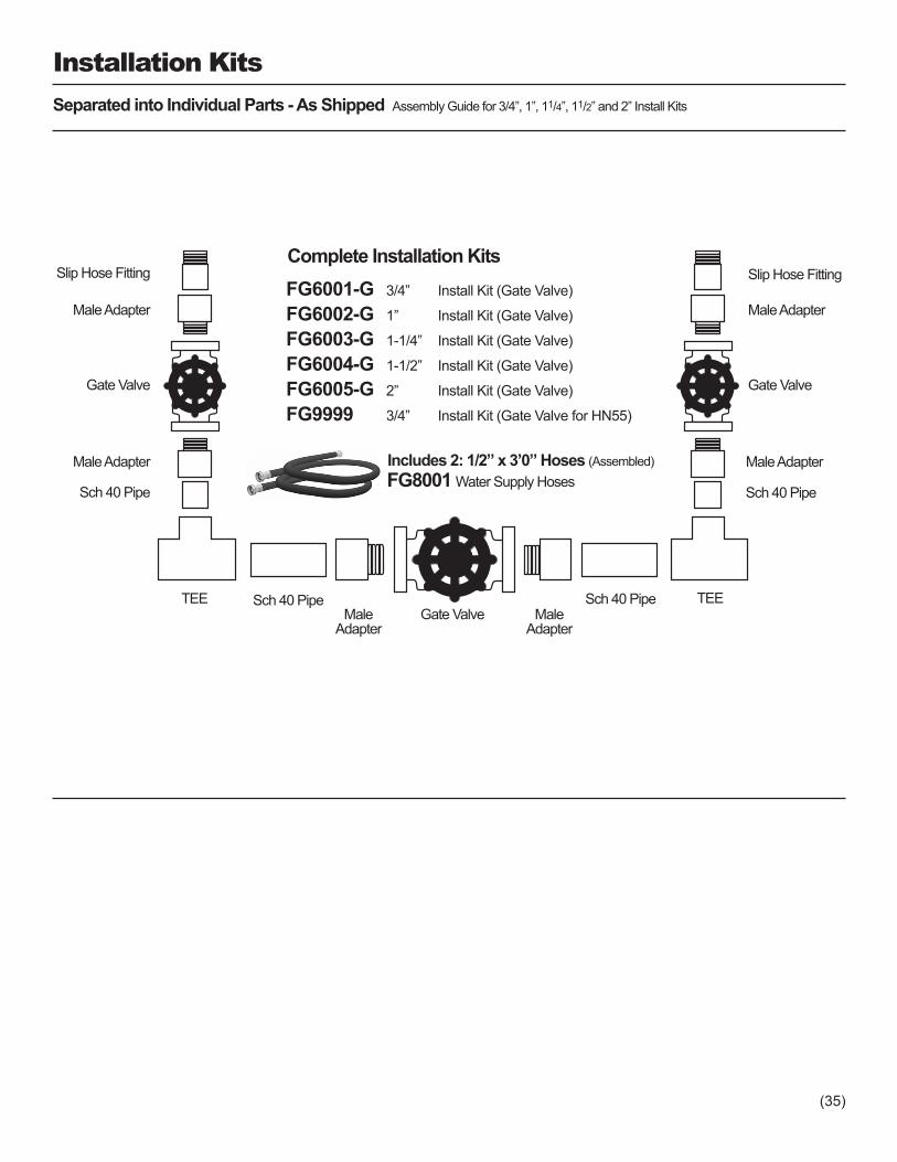
Installation Kits
Includes 2: 1/2” x 3’0” Hoses (Assembled)FG8001 Water Supply Hoses
FG6001-G 3/4” Install Kit (Gate Valve)
FG6002-G 1” Install Kit (Gate Valve)
FG6003-G 1-1/4” Install Kit (Gate Valve)
FG6004-G 1-1/2” Install Kit (Gate Valve)
FG6005-G 2” Install Kit (Gate Valve)
FG9999 3/4” Install Kit (Gate Valve for HN55)
Separated into Individual Parts - As Shipped Assembly Guide for 3/4”, 1”, 11/4”, 11/2” and 2” Install Kits
Slip Hose Fitting
Male Adapter
Gate Valve
Male Adapter
Sch 40 Pipe
Gate ValveMaleAdapter
MaleAdapter
Sch 40 Pipe
Complete Installation Kits
TEE TEESch 40 Pipe
Slip Hose Fitting
Male Adapter
Gate Valve
Male Adapter
Sch 40 Pipe
(35)

11. WarrantyUnited States Warranty Policy*
Water Motor Warranty:The water motor is warranted to be free from defects in materials and workmanship for a period of two years from the date of purchase. During the first six-month period, should the water motor fail, it will be replaced with a new water motor and a new warranty. For the balance of the warranty period, should the water motor fail, it will be rebuilt or replaced, at the option of Chemilizer, and warranted for the balance of the original warranty period. This warranty does not cover damage due to misuse, abuse, neglect, or alteration. This warranty does not cover damage that occurs in transit. This warranty does not cover any labor or shipping charges for removal and reinstallation. This warranty is void if the serial number label is removed from the unit. This warranty is non-transferable.
Injection Control Panel:The Injection Control Panel is warranted to be free from defects in materials and workmanship for a period of one year from the date of purchase. At its discretion, Chemilizer will repair or replace the Injection Control Panel at no charge if the Injection Control Panel is determined to be defective when operated under normal operating conditions, and warranted for the balance of the original warranty period. This warranty does not cover damage due to misuse, abuse, neglect, dam-age resulting from continued direct exposure to sunlight, or alteration. This warranty does not cover any labor or shipping charges for removal and reinstallation. This warranty is non-transferable.
Chemical Pump: The Chemical Pump is not covered under warranty. Chemilizer Products, Inc. has no control over the types of materials or chemicals that will be used in this equipment; therefore we can not guarantee the chemical pump to be impervious to each and every chemical. Wear of seals and other components is normal and will vary depending on operating conditions and the chemicals being used. Wear to the pump and components, due to use or chemical attack, are not covered by war-ranty.
Warranty Claims:Return to your local dealer, or to Chemilizer Products, Inc. Proof of purchase date, serial number, and an explanation of the complaint must accompany the merchandise. In the event no warranty card is on file or proof of purchase is not avail-able, manufacture date on the unit will be used to determine warranty period. Final determination of all warranty claims will be made by manufacturer.
Miscellaneous Products:Chemilizer does not warrant parts manufactured by outside sources which are used in the assembly of other product of-fered by Chemilizer. This includes parts used in installation kits such as gate valves and PVC components.
Before sending merchandise to Chemilizer Products, call for a return authorization number.
1-800-234-7211*This Warranty Policy applies only to units and component parts purchased and installed in the United States.
To the extent permitted by law, this warranty is made expressly in place of all other guarantees or warranties, express or implied, with respect to quality, merchantability, or fitness for a particular purpose. Chemilizer hereby disclaims any other express or implied warranties. Some states do not allow limitations on how long an implied warranty lasts or their disclaimer so the above limitations may not apply to you. This warranty gives you specific legal rights, and you may also have other rights which vary from state to state.
(36)
12. Contact UsThank you for purchasing a Chemilizer injector!
Chemilizer is committed to manufacturing the highest quality product to fill your injection needs, and to providing you with the best service possible.
To help achieve this, we ask that you please take a moment to fill out and send in the warranty card. You can also fill out the warranty online at our web site, www.chemilizer.com
Chemilizer Products, Inc.230 Commerce Drive NorthLargo, FL 33770
Telephone: (727) 518-1665Fax: (727) 559-8266
Web: www.chemilizer.comEmail: [email protected]
Hours of Operation:Monday – Friday8:30 AM – 5:00 PM Eastern Time
(37)