Chemical Visualization of Latent Prints - NCJRS · Chemical Visualization of Latent Prints . ......
61
The author(s) shown below used Federal funds provided by the U.S. Department of Justice and prepared the following final report: Document Title: Chemical Visualization of Latent Prints Author: Evan Durnal Document No.: 238008 Date Received: March 2012 Award Number: 2008-NI-CX-K012 This report has not been published by the U.S. Department of Justice. To provide better customer service, NCJRS has made this Federally- funded grant final report available electronically in addition to traditional paper copies. Opinions or points of view expressed are those of the author(s) and do not necessarily reflect the official position or policies of the U.S. Department of Justice.
Transcript of Chemical Visualization of Latent Prints - NCJRS · Chemical Visualization of Latent Prints . ......

The author(s) shown below used Federal funds provided by the U.S. Department of Justice and prepared the following final report:
Document Title: Chemical Visualization of Latent Prints
Author: Evan Durnal Document No.: 238008
Date Received: March 2012 Award Number: 2008-NI-CX-K012
This report has not been published by the U.S. Department of Justice. To provide better customer service, NCJRS has made this Federally-funded grant final report available electronically in addition to traditional paper copies.
Opinions or points of view expressed are those of the author(s) and do not necessarily reflect
the official position or policies of the U.S. Department of Justice.

i
Chemical Visualization of Latent Prints Grant # 2008-NI-CX-K012
Final Report
For
National Institute of Justice Office of Justice Programs U.S. Department of Justice
MRI Project No. 110636
July 30, 2010
castellv
Text Box
This project was supported by Award No. 2008-NI-CX-K012 awarded by the National Institute of Justice, Office of Justice Programs, US Department of Justice. The opinions, findings, and conclusions or recommendations expressed in this publication/program/exhibition are those of the author(s) and do not necessarily reflect the views of the Department of Justice. NIJ defines publications as any planned, written, visual or sound material substantively based on the project, formally prepared by the grant recipient for dissemination to the public.

Preface The primary author of this report was Mr. Evan Durnal. The report was reviewed by Dr. James Egan and Mr. Tim Lanigan. This document was created in fulfillment of cooperative agreement contract # 2008-NI-CX-K012 Latent Print Chemical Visualization. This document was revised from the DRAFT final report based upon comments provided by The National Institute of Justice review panel. The period of performance for this contract was October 1, 2008 thru July 30, 2010. For technical questions or clarifications regarding this document, contact Dr. James Egan.
MIDWEST RESEARCH INSTITUTE
//s// Mr. Evan Durnal
NIJ Technical Lead Approved: //s// Dr. James Egan NIJ Principal Investigator July 30, 2010
ii

Contents Preface ................................................................................................................................. ii Tables ................................................................................................................................. iv Figures................................................................................................................................ iv Section 1. Executive Summary ..........................................................................................1 Section 2. Acronyms ..........................................................................................................4 Section 3. Introduction .......................................................................................................5 Section 4. Experimental Approach ....................................................................................7
4.1 Initial Solution Evaluation ........................................................................7 4.2 Porous & Non-Porous Substrate Evaluation ...........................................11 4.3 Volunteer Enrollment .............................................................................15 4.4 Fingerprint Stability Experiments ...........................................................16 4.5 Blind Study .............................................................................................17
Section 5. Results .............................................................................................................19 5.1 Porous & Non-Porous Substrate Results ................................................19 5.2 Stability Study Results ............................................................................27 5.3 Blind Study Results ................................................................................29 5.4 Blind Study Results ................................................................................30
Section 6. Conclusions and Path Forward .......................................................................34 6.1 Conclusions .............................................................................................34 6.2 Path Forward ...........................................................................................34
Appendix A ................................................................................................................... A - 1 Appendix B ....................................................................................................................B - 1 Appendix C ....................................................................................................................C - 1 Attachment I................................................................................................. Attachment I- 1 Attachment II ............................................................................................. Attachment II - 1 Attachment III ........................................................................................... Attachment III - 1
iii

Tables Table 1. List of Acronyms ...................................................................................................4 Table 2. COTS Products Investigated ..................................................................................7 Table 3. Chemical Developers Investigated ........................................................................8 Table 4. Solvent Effects on Latent Prints ..........................................................................10 Table 5. Sample Matrix for Stability Study .......................................................................17 Table 6. Sample Matrix for Blind Study ............................................................................18 Table 7. Stability Study Sample Naming Scheme .............................................................28 Table 8. Non-Porous Stability Study Images Successfully Enrolled at Each Time Point
and Environmental Condition .........................................................................28 Table 9. Blind Study Sample Naming Scheme ..................................................................31 Table 10. Blind Study Results ...........................................................................................33 Figures Figure 1. Phenolic resin developed with (A) blue-colored Leuco dye solution and (B)
yellow-colored Leuco dye solution visualized under blue excitation wavelength ........................................................................................................1
Figure 2. Glass beaker treated with alcoholic phenolic resin solution followed by exposure to fluorescent Leuco dye. ..................................................................1
Figure 3. Microscopic digital image examining the bare metal protected by fingerprint oils versus acid-vapor corroded bare material ..................................................2
Figure 4. Digital photographs (A) before and (B) after exposure to iron salt solution. ......3 Figure 5. Unaltered photographs showing solvent impact on latent prints deposited on
slides ...............................................................................................................10 Figure 6. Dip & Spray Set-up of Select Dye Solutions .....................................................11 Figure 7. Emission profile of blue LED measured by Horiba Jobin Yvon FluoroMax-3
fluorimeter ......................................................................................................13 Figure 8. The chemical structures for the lawsone and juglone isomers ...........................14 Figure 9. IRISCard Pro 4 business card scanner ................................................................15 Figure 10. DigitalPersona fingerprint scanner ...................................................................15 Figure 11. VeriFinger software graphical interface with actual image on left side and the
extracted minutiae depicted on the right (in green) ........................................16 Figure 12. A stainless steel plate handled by fingersis placed within an inverted glass
beaker. A small amount of Tek GelTM is placed in the vicinity of the metal surface for 24 hours. .......................................................................................19
Figure 13. Fingerprint ridge detail photographed after being treated for 24 hours with Tek GelTM; (A) finger coated with oils from forehead swipe and (B) finger not coated with oils. ..............................................................................................20
Figure 14. Latent prints developed with phenolic resin on glass slide (left image) and aluminum can (right image) with blue LED excitation ..................................21
iv
v
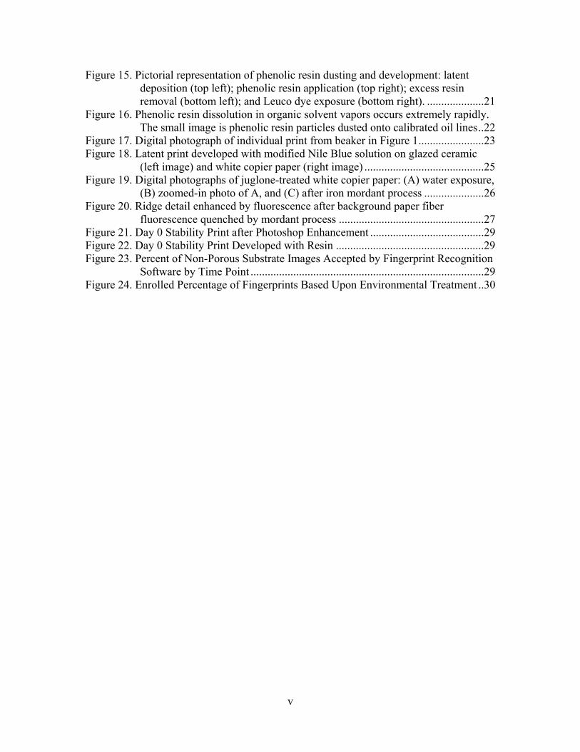
Figure 15. Pictorial representation of phenolic resin dusting and development: latent deposition (top left); phenolic resin application (top right); excess resin removal (bottom left); and Leuco dye exposure (bottom right). ....................21
Figure 16. Phenolic resin dissolution in organic solvent vapors occurs extremely rapidly. The small image is phenolic resin particles dusted onto calibrated oil lines ..22
Figure 17. Digital photograph of individual print from beaker in Figure 1 .......................23 Figure 18. Latent print developed with modified Nile Blue solution on glazed ceramic
(left image) and white copier paper (right image) ..........................................25 Figure 19. Digital photographs of juglone-treated white copier paper: (A) water exposure,
(B) zoomed-in photo of A, and (C) after iron mordant process .....................26 Figure 20. Ridge detail enhanced by fluorescence after background paper fiber
fluorescence quenched by mordant process ...................................................27 Figure 21. Day 0 Stability Print after Photoshop Enhancement ........................................29 Figure 22. Day 0 Stability Print Developed with Resin ....................................................29 Figure 23. Percent of Non-Porous Substrate Images Accepted by Fingerprint Recognition
Software by Time Point ..................................................................................29 Figure 24. Enrolled Percentage of Fingerprints Based Upon Environmental Treatment ..30

Section 1. Executive Summary Midwest Research Institute investigated new chemical processing methods designed to provide law enforcement personnel with alternative products. The fingerprint development techniques investigated focused on providing the following attributes: non-toxicity and non-irritating, cost-effective, provide instantaneous ridge visualization (with or without alternate light sources), high-resolution fingerprint ridge detail for comparison purposes, minimal pre- and post-treatment requirements, and capable of visualizing prints on porous and/or non-porous surfaces. Three (3) new techniques were developed during this research investigation. The first method used a phenolic resin powder that can be substituted for current fingerprint dusting kits. The phenolic resin, a light pink solid, adhered to fingerprint oils when applied using typical dusting procedures. The dusted print can be immediately observed on dark backgrounds. Further print development was accomplished by applying an aqueous solution containing a Leuco dye which underwent chemical transitions due to the acidic pH present in the phenolic resin. Leuco dyes can be chosen based upon the background interference present in/on the developed surface. A color change, anywhere in the visible spectrum, was observed when specific Leuco dye solutions dried on the phenolic resin. Leuco dye fluorescence can also
be used as a further image contrasting tool as observed in Figure 1. This procedure worked on metal, ceramic, and other non-porous surfaces; but works best on glass. The reason glass was an ideal substrate relied upon the transparency and dual-sided nature. The phenolic resin can be applied as an alcohol solution opposite to the glass surface typically handled (i.e. the internal surface can be used to visualize the fingerprints left on the external surface). Once dried, the resin was exposed using a fluorescent Leuco dye. Light-emitting diode (LED) excitation causes the fluorescence emission to be transported and reflected into the glass because of the waveguiding properties of glass materials. Figure 2 illustrates the striking image of a glass treated
Figure 1. Phenolic resin developed with (A) blue-colored Leuco dye solution and (B) yellow-colored Leuco dye solution visualized under blue excitation wavelength
Figure 2. Glass beaker treated with alcoholic phenolic resin solution followed by exposure to fluorescent Leuco dye.
1

in this manner to visualize multiple prints present on the external material surface. The image in Figure 2 was taken to indicate how many prints could be seen from this method. Additional images of better quality close-up photos were left to later sections. This procedure lends itself best to field investigations because:
• Only one (1) dusting powder is required for all surfaces – the phenolic resin; • Phenolic resin can be applied using current dusting techniques; • Phenolic resin color can be changed depending on which Leuco dye solution is
used for development; • Phenolic resin can be gelled to create a permanent print; and • All chemicals and solutions are non-toxic and have been used to create Crayola
products for kids. The second method is a procedural modification to make metal etching with acidic vapors safer for criminal investigators. Fingerprints left on metals protect the surface integrity from corrosive vapors such as hydrochloric acid (HCl). The protective salts and oils act as an etch mask and prevents corrosion with respect to bare, exposed metal. The result is fingerprint ridge impressions left behind because of the differential etching. Forensic examiners have used HCl vapor in the past but it must be done in a chemical fume hood. The Contractor identified a commercial (COTS) product called Tek GelTM that is used for artistic cement detailing. The fluorescent gel contains HCl that slowly vaporized over time and can be used to etch fingerprints left behind on metal surfaces as illustrated in Figure 3.
Figure 3. Microscopic digital image examining the bare metal protected by fingerprint oils versus acid-vapor corroded bare material
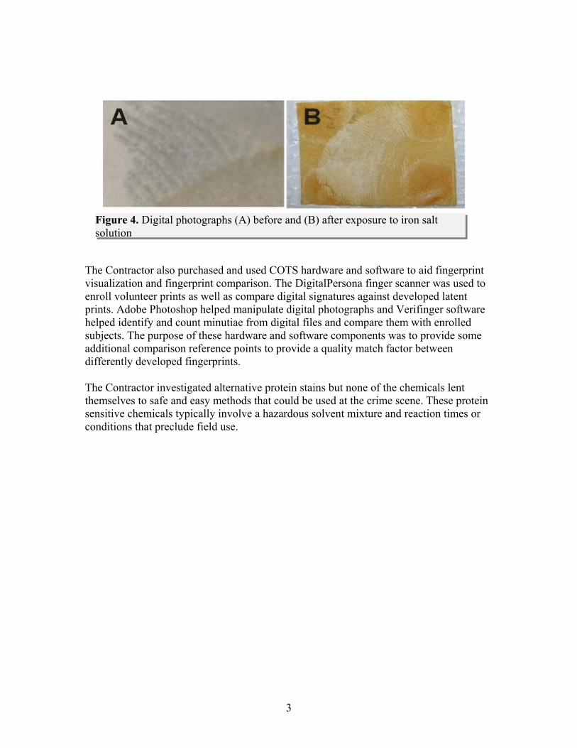
The third method uses stains and dyes extracted from natural plant sources to visualize fingerprints left on porous surfaces (paper) after being handled. Several plant-derived stains including juglone, lawsone, and osage-orange were used to treat paper. All three dye solutions preferentially stain the cellulose used in paper products. The oils left behind from a fingerprint touch coat the cellulose fibers and prevent them from being stained. Wetting the paper surface causes a fingerprint impression to appear because of the increased contrast required to observe the faint color difference between the cellulose fibers coated with fingerprint oil and those stained with plant dyes. Other dye industry techniques were used to increase this contrast such as mordant creation; using iron (Fe) salts to create anchored dyes with darker colors. (see next page) depicts the difference between before and after mordant creation.
Figure 4
2
3
Figure 4. Digital photographs (A) before and (B) after exposure to iron salt solution
The Contractor also purchased and used COTS hardware and software to aid fingerprint visualization and fingerprint comparison. The DigitalPersona finger scanner was used to enroll volunteer prints as well as compare digital signatures against developed latent prints. Adobe Photoshop helped manipulate digital photographs and Verifinger software helped identify and count minutiae from digital files and compare them with enrolled subjects. The purpose of these hardware and software components was to provide some additional comparison reference points to provide a quality match factor between differently developed fingerprints. The Contractor investigated alternative protein stains but none of the chemicals lent themselves to safe and easy methods that could be used at the crime scene. These protein sensitive chemicals typically involve a hazardous solvent mixture and reaction times or conditions that preclude field use.

Section 2. Acronyms
Table 1. List of Acronyms Acronym Description
CAS# Chemical Abstract Service Number CHP Chemical Hygiene Plan
COTS Commercial-of-the-Shelf DFO 1,8-Diazafluoren-9-one DI De-ionized
HCl Hydrochloric Acid IRB Internal Review Board ISO International Standards Organization LED Light Emitting Diode mg Milligram mL MilliLiter MRI Midwest Research Institute NA Not Applicable NIJ National Institute of Justice
QAU Quality Assurance Unit QC Quality Control RH Relative Humidity RT Room Temperature
SOP Standard Operating Procedure TP Test Procedure
TPPS Test Plan, Procedure, and Schedule TSWG Technical Scientific Working Group WBS Work Breakdown Structure UV Ultra Violet
4

Section 3. Introduction NIJ requested concepts to improve latent identification/examination technologies. The Contractor investigated new latent fingerprint treatments that eliminate/reduce law enforcement personnel exposure to hazardous materials such as dusting powders, cyanoacrylate (C6H7NO2) used for fuming fingerprints, ninhydrin (1,2,3-triketo-hydrindene hydrate) used for staining protein residue, silver nitrate (AgNO3) used for staining, and DFO (1,8-Diazafluoren-9-one) used for staining proteins.1 Although each approved process has been used for years in the forensic field, scientists continue to discover new methods to reduce print development safety hazards while increasing the informational detail obtained. Major cyanoacrylate exposure concerns are inhalation, ingestion, and dermal exposure. Cyanoacrylate polymerizes upon contact with water, which creates health concerns with mucous membrane contact, specifically when inhaled or ingested. Respiratory problems are the highest concern when dealing with cyanoacrylate in current fuming methods. Dermal exposure to cyanoacrylate is generally not a large concern because initial uses included medicinal sutures. Skin irritations or chemical burns are only expected if the skin is exposed to large amounts of cyanoacrylate. Ninhydrin reagent on the other hand, is most harmful when skin or eye exposure occurs. Ninhydrin itself is a toxic substance and is made more hazardous when combined with various solvents during the development process. Recurring exposure often leads to chemical sensitization, allergy formation and increasingly intense reaction. Silver nitrate-based development techniques can also be extremely hazardous. Silver nitrate is a strong oxidizing agent, is highly corrosive, and can be fatal if swallowed. Repeated exposure to silver nitrate may cause permanent skin discoloration and is suspected to contribute to lung disease and may cause blindness. The major objective involved identifying chemicals or processes that could be adapted for first responder and crime scene investigation units to process prints at the scene with limited or no safety hazards. The fingerprint visualization techniques developed by the Contractor attempted to combine the following attributes: non-toxicity and non-irritating, cost-effective, provide instantaneous ridge visualization (with or without alternate light sources), high-resolution fingerprint ridge detail for comparative purposes, minimal pre- and post-treatment requirements, and capable of visualizing prints on porous and non-porous surfaces. Although several chemicals investigated during this grant period exhibited promise for developing latent fingerprints – none were considered to be developed to the readiness level required for law enforcement adoption without further testing and evaluation. The Contractor focused on the typical chemicals found in latent print residues. The residues are comprised of organic (such as pyruvic, lactic, and amino acids and lipids)
1 Advances in Fingerprint Technology. Lee, H.C.; Gaensslen, R.E. 2nd ed. 2001. CRC Press LLC.
5

6
and inorganic (such as salts) species.2 Different chemical processes and formulations were investigated to provide the possibility for treating multiple surfaces while targeting some of the unique chemicals present in a latent print deposition across varying time intervals. Amino acid-based techniques were avoided based upon the amount of research devoted to ninhydrin and ninhydrin-related analogues. These techniques are fairly sensitive to amino acid presence but often involve heating steps to create the chemical bond and fluorescence signal for detection. Several companies, most notably Molecular Probes, Inc. (a subsidiary of Invitrogen),3 have a vast list of alternative amino acid reactive dyes that a forensic scientist could also choose. The disadvantages of these products include the price per gram and the requirement for very controlled reaction conditions to complete the labeling process. Priority was given to chemicals that would reduce the development process, time involved, and risk to the forensic examiner. The end goal was to identify methods that could be deployed at the crime scene with little training and operator hazards. The research described represents the initial developmental stages of four (4) methods that eventually could be adapted for forensic utility. As part of this document, the Contractor has delivered draft procedures describing all information necessary to reproduce latent fingerprint images on any of the studied surfaces and is provided as attachments to this report. Final chemical formulations are detailed and are fairly inexpensive to purchase or freshly prepare. Technical limitations such as environmental and durational requirements of evidentiary material are also reported.
2 Latent Fingerprint Composition. FBI Training 2002. Victoria Forensic Science Centre Fingerprint
Branch. 3 www.invitrogen.com
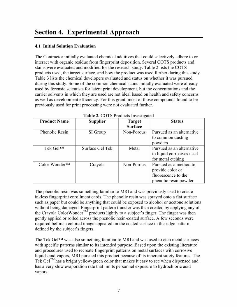
Section 4. Experimental Approach 4.1 Initial Solution Evaluation
The Contractor initially evaluated chemical additives that could selectively adhere to or interact with organic residue from fingerprint deposition. Several COTS products and stains were evaluated and modified for the research study. Table 2 lists the COTS products used, the target surface, and how the product was used further during this study. Table 3 lists the chemical developers evaluated and status on whether it was pursued during this study. Some of the common chemical stains initially evaluated were already used by forensic scientists for latent print development, but the concentrations and the carrier solvents in which they are used are not ideal based on health and safety concerns as well as development efficiency. For this grant, most of those compounds found to be previously used for print processing were not evaluated further.
Table 2. COTS Products Investigated Product Name Supplier Target
Surface Status
Phenolic Resin SI Group Non-Porous Pursued as an alternative to common dusting powders
Tek Gel™ Surface Gel Tek Metal Pursued as an alternative to liquid corrosives used for metal etching
Color Wonder™ Crayola Non-Porous Pursued as a method to provide color or fluorescence to the phenolic resin powder
The phenolic resin was something familiar to MRI and was previously used to create inkless fingerprint enrollment cards. The phenolic resin was sprayed onto a flat surface such as paper but could be anything that could be exposed to alcohol or acetone solutions without being damaged. Fingerprint pattern transfer was then created by applying any of the Crayola ColorWonderTM products lightly to a subject’s finger. The finger was then gently applied or rolled across the phenolic resin-coated surface. A few seconds were required before a colored image appeared on the coated surface in the ridge pattern defined by the subject’s fingers. The Tek Gel™ was also something familiar to MRI and was used to etch metal surfaces with specific patterns similar to its intended purpose. Based upon the existing literature1 and procedures used to recreate fingerprint patterns on metal surfaces with corrosive liquids and vapors, MRI pursued this product because of its inherent safety features. The Tek GelTM has a bright yellow-green color that makes it easy to see when dispensed and has a very slow evaporation rate that limits personnel exposure to hydrochloric acid vapors.
7

Table 3. Chemical Developers Investigated
Chemical Name Common Name CAS # Dye Class Target
Surface Status Previous Forensic
Reference
4-Aminoazobenzene Solvent Yellow 1 60-09-3 Monoazo P*/NP$ Stopped NA
4-dimethylamino-2-methylazobenzene -- 54-88-6 Monoazo P/NP Stopped NA
3,6-Bis(dimethylamino)acridine
hydrochloride
Acridine Orange 65-61-2 Cationic
acridine P/NP Stopped 1
N-(2,4-Dinitrophenyl)-1,4-phenylenediamine,
Disperse Yellow 9 6373-73-5 Dinitro P/NP Stopped
Fat Brown B Solvent Red 3 6535-42-8 Monoazo P/NP Stopped
5-Hydroxy-1,4- Naphthoquinone Juglone 481-39-0 -- P Pursued NA
2-Hydroxy-1,4- Naphthoquinone Lawsone 83-72-7 -- P Stopped 4
Malachite Green carbinol base Solvent Green 1 510-13-4 Triphenyl
methane P/NP Stopped
Nile Blue Sulfate Nile Blue A 3625-57-8 Oxazine P/NP Pursued 1
Oil Red EGN Solvent Red 26 4477-79-6 Disazo P/NP Stopped
Oil Red O Solvent Red 27 1320-06-5 Disazo P/NP Stopped 1
8

9
Chemical Name Common Name CAS # Dye Class Target
Surface Status Previous Forensic
Reference
ortho-phthaldialdehyde OPA 643-79-8 Xanthene P/NP Stopped 1
4-Phenylazo-m-phenylenediamine
Solvent Orange 3 495-54-5 Monoazo P/NP Stopped
4-Phenylazophenol Solvent Yellow 7 1689-82-3 Monoazo P/NP Stopped
Sudan Black B Solvent Black 3 4197-25-5 Disazo P/NP Stopped 1
Sudan IV Solvent Red 24 85-83-6 Disazo P/NP Stopped 1
2,4-Dihydroxyazobenzene Sudan Orange G 2051-85-6 Monoazo P/NP Stopped
-- Osage Orange Extract -- Natural P Pursued
* P: Porous; $NP: Non-porous; NA: Not Applicable 1. Advances in Fingerprint Technology. Lee, H.C.; Gaensslen, R.E. 2nd ed. 2001. CRC Press LLC. 4. Jelly, R; Lewis, SW; Lennard, C.; Lim, KF; Almog, J. Chem Commun. (2008) 3513-3515

Figure 5. Unaltered photographs showing solvent impact on latent prints deposited on slides
Prior to formulating potential fingerprint development solutions, six (6) solvents were tested to determine how each would degrade or dissolve a latent print. Prints were placed on glass slides by touching them briefly to transfer ridge detail. Subjects were not asked to wash their hands or touch their foreheads before this print deposition. Test prints were sprayed with solvent as well as immersed in each test solvent followed by visual observation of impact on individual print detail. The results guided the use of carrier solvents chosen to dissolve each compound and identify possible solvent combinations that could be used to increase the preferential binding of each dye with the latent print. Table 4 lists the results determined by soaking latent prints in the six (6) different solvents. Minimal impact ocwith aqueous-based solutions because only the salt residues are dissolved while the transferred oils remain intact. The organic-based solvents, especially acetone and methylene chloride dissolve the hydrophobic oils much better. Figure 5 provides photographic images before and after dipping prints in an aqueous solution versus dichloromethane solution. The lower imagesshow how the organic solvent, dichloromethane removes much more ridge detail than the aqueous wash.
curs
a
Table 4. Solvent Effects on Latent Prints
Solvent Observations Acetone Moderate Degradation Methanol Minimal Degradation
Water Minimal Degradation Methylene Chloride Significant Degradation
Ethanol Minimal Degradation Isopropyl Alcohol Significant Degradation
- Minimal degradation meant the print was no different after the print was exposed to solvent
- Moderate degradation meant parts of the print ridge detail were removed or faded
- Significant degradation meant most of the ridge detail was removed or faded
Fifty (50) mg of each dye and stain listed in Table 3 was weighed and combined with ten (10) mL of ethanol and ninety (90) mL of de-ionized (DI) water. The solubility of each compound in solution was noted and the solvent composition of each individual solution was altered until the compound was fully dissolved. Small aliquots of each dye/stain
10

solution were used to evaluate the tendency of each dye to preferentially bind to latent print residues. The prints were both dipped in and sprayed with all solutions. Photographic images were captured for each dye test to observe how the prints were affected and/or stained. Figure 6 depicts some of the colored solutions initially evaluated.
Figure 6. Dip & Spray Set-up of Select Dye Solutions
4.2 Porous & Non-Porous Substrate Evaluation Porous and non-porous surfaces were treated independently because fingerprint ridge detail is impacted by the type of material handled. Porous surfaces tend to soak up the various fingerprint chemicals and allow better retention over longer time periods. Chemicals found in fingerprints deposited on non-porous surfaces will create a thin film coating the particular surface and will more easily evaporate over time due to the lack of adsorbent or absorbent functionalities. Different processing techniques were evaluated for the two surface types. 4.2.1 Non-Porous Substrates 4.2.1.1 Metal Surfaces One example of a common non-porous substrate of forensic importance is metal. Metals such as brass used for ammunition casings and common tools, and stainless steel used for common tools often are critical evidentiary material that may contain suspect fingerprints. Metals provide a relatively smooth surface that prevents fingerprint oil deposition from penetrating the bulk material. Fingerprints on metal surfaces are typically developed through the use of cyanoacrylate fuming followed by staining or dye absorption1, or by metal etching techniques accomplished by acidic vapor exposure5. Recently, investigators from England have discovered using electrochemical etching6,7 or
5 http://www.swgfast.org/Glossary_Consolidated_ver_1.pdf 6 Williams, G; et al. J Forensic Sci. 46 (2001) 1085-1092. 7 Williams, G.; et al. Forensic Sci. Intl.167 (2007) 102-109
11

high temperature8 procedures. The procedure takes advantage of salt deposits remaining from physical contact by passing electrical current through the metal material to differentially corrode or etch the fingerprint salts on the metal surface. The resultant pattern is a fingerprint ridge based on the salt residue. The method has been successfully shown to visualize prints left on brass bullet casings. Acidic vapor mentioned above was also used during this study by replacing the toxic liquid acids with a commercial-grade gel used in cement marking. The goal was to use a less dangerous form factor of the acid and eliminate heating the concentrated liquid to facilitate acid vapors. Surface Gel Tek™ offers a product marketed as a gelled hydrochloric acid (HCl)9. The Material Safety Data Sheet (MSDS) for the product is included in Appendix B. The gel is a fluorescent green to clearly visualize the presence of the product. The product contains 16% HCl as the active ingredient. The Surface Gel Tek™ works similar to heated sulfuric acid fumes without the requiring high temperature. The HCl in the gel gradually volatilizes over time and facilitates the same differential metal etching as the vapor methods currently used. 4.2.1.2 Non-Metal Surfaces (Glass, Ceramic, etc.) The Contractor brainstormed several concepts to propose a technical solution capable of capturing fingerprints that were deposited onto a non-porous surface. Several ideas were identified. The second concept adopted for this research project focused on a well-known children’s toy. The most promising candidate was the ColorWonder® product line developed by Crayola. The underlying chemical principle is simple and straightforward. The binary component system consists of a color former and a color changer/developer.
• The color former is a thermal resin or liquid having varying viscosities. The color former liquid is initially colorless with no detectable visible emission under ambient, daylight conditions.
• The color changer/developer is a treated surface containing the necessary reactants to convert the color former into a chemical that appears in the visible spectrum when combined.
The critical components used in the Crayola® patents includes a Leuco dye used as the color former and a phenolic resin used as the color changer. Leuco dyes are pH sensitive, and exhibit halochromic properties10. Leuco dyes usually have a colored and non-colored chemical structure that undergoes a transition when the transition pH is reached. The Crayola products are formulated in a neutral pH solution or wax that can be applied by spray or transported via touch to specially-treated paper. The paper contains a coating comprised of a phenolic resin exhibiting a pH much lower than the transition point of the Leuco dyes used in the complementary liquid. When the two components are combined the resulting image becomes colored almost instantaneously.
8 Bond,J J. Forensic Sci. 53 (2008) 812-22 9 http://surfacegeltek.com/documents.html 10 Sigma-Aldrich Handbook of Stains, Dyes, and Indicators, ed Green, F; Aldrich Chemical Company; Milwaukee, WI (1990).
12

Crayola sells six (6) variations of color former mixtures resulting in different visible colors when applied onto the color developer surface: red, orange, yellow, green, blue, and purple. One thing experienced during this study was the importance of interfering background colors. It was difficult to resolve ridge detail if the fingerprint chemical developer was a similar color to the material background. The different color former mixtures allow multi-colored images that were able to alleviate the resolution and contrast issue based upon the background surface color. One can choose the fingerprint color detail with multiple spray applications. Another beneficial factor for the Crayola Leuco dyes was the intrinsic fluorescence of the colored moiety that provided further contrast and resolution between the latent ridge detail and the background surface, as long as there was no background fluorescence in the same spectral region. The Contractor used a COTS light-emitting diode (LED) source that was in the blue region of the visible spectrum. The LED emission was measured with a Horiba Jobin Yvon FluoroMax-3 (S/N 3680B) instrument to determine the emission profile of the blue LEDs. The blue LED had a maximum emission wavelength of 465 nm ( ). Figure 7
0
200000
400000
600000
800000
1000000
1200000
1400000
1600000
350 375 400 425 450 475 500 525 550
Wavelength (nm)
Inte
nsity
(a.u
.)
Figure 7. Emission profile of blue LED measured by Horiba Jobin Yvon FluoroMax-3 fluorimeter
The Contractor acquired a sample phenolic resin, HRJ-2053 (SI Group; Schenactady, NY), in the form of solid flakes. The solid flakes can be ground to produce a fine dust that can be applied to different non-porous surfaces suspected of containing latent prints. The phenolic resin powder adhered well to the latent fingerprint oils and selective removal of stray dust can be performed with canned air. The resultant ridge detail can be subjected to an aqueous dilution of the specific color former that provided optimal viewing and digital recording. The color former concentration can be varied to achieve both a visible color and a fluorescent signal based upon the specific excitation wavelength required.
13

4.2.2 Porous Substrates 4.2.2.1 Natural Product Stains Plant-derived stains were chosen to develop fingerprints on copier paper after being handled by volunteers. Three (3) different extracted plant dyes were investigated: lawsone, juglone, and dyes extracted from the bark of the Osage Orange tree. Lawsone and juglone are structural isomers, both having the naphthoquinone moiety with the hydroxyl group in a different position relative to the double-bonded oxygen atoms (see Figure 8). Lawsone (2-hydroxy-1,4-naphthoquinone) is derived from the henna plant while juglone (2-hydroxy-1,4-naphthoquinone) comes from the black walnut. Both lawsone and juglone chemicals were purchased from Sigma-Aldrich. The Osage Orange bark extract solution contains a mixture of the Morin and Maclurin dyes11. The extract was performed by boiling Osage Orange bark in water for several hours. The resultant extract was diluted to use for the fingerprint development tests.
Figure 8. The chemical structures for the lawsone and juglone isomers
All three (3) plant-derived stains exhibited better adherence to the cellulose paper fibers that were not handled by touch. The fingerprint oils deposited on the cellulose fibers prevented these fibers from adsorbing the dyes as well as the paper fibers not handled. However, the effect was only visible when the paper was wetted because the water increased the contrast between fibers with and without adsorbed dye. Another way to increase the color contrast was to treat the dye-stained paper with iron sulfate solution to create a darker mordant. An example of the difference after the mordant process was presented in Figure 4 B in the Executive Summary Section. 4.2.2.2 Nile Red Nile Blue A has been used to enhance cyanoacrylate fumed prints but has never been used as a stain to visualize native prints, either on porous or non-porous surfaces. It is known Nile Blue solutions contain impurities of Nile Blue oxazone, a degradation product resulting in different chemical staining properties.7,12 The chemical reaction below depicts the two (2) resultant chemical species.
Nile Blue A Nile Red
H2O
→
11 The Merck Index. 13th ed. (2001) Merck & Co.; Whitehouse Station, NJ. 12 McGee-Russell, S.M.; Smale, N.B. Quart. J. Micr. Sci 104 (1963) 109
14
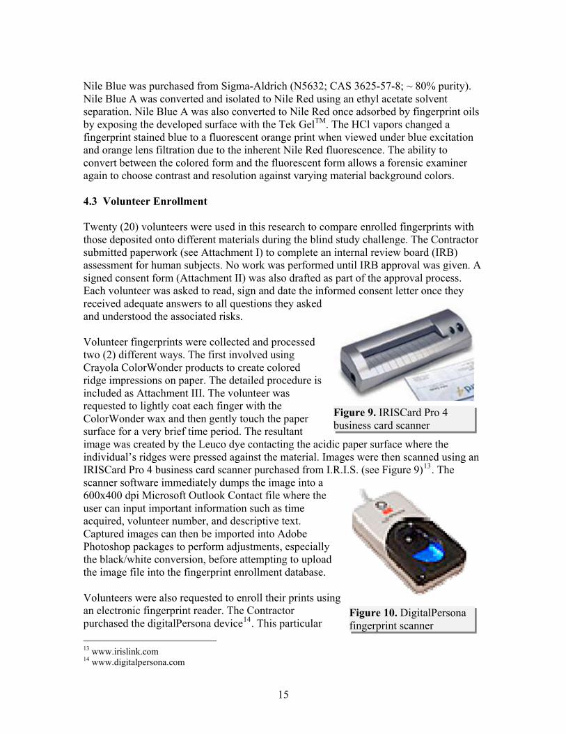
Nile Blue was purchased from Sigma-Aldrich (N5632; CAS 3625-57-8; ~ 80% purity). Nile Blue A was converted and isolated to Nile Red using an ethyl acetate solvent separation. Nile Blue A was also converted to Nile Red once adsorbed by fingerprint oils by exposing the developed surface with the Tek GelTM. The HCl vapors changed a fingerprint stained blue to a fluorescent orange print when viewed under blue excitation and orange lens filtration due to the inherent Nile Red fluorescence. The ability to convert between the colored form and the fluorescent form allows a forensic examiner again to choose contrast and resolution against varying material background colors. 4.3 Volunteer Enrollment Twenty (20) volunteers were used in this research to compare enrolled fingerprints with those deposited onto different materials during the blind study challenge. The Contractor submitted paperwork (see Attachment I) to complete an internal review board (IRB) assessment for human subjects. No work was performed until IRB approval was given. A signed consent form (Attachment II) was also drafted as part of the approval process. Each volunteer was asked to read, sign and date the informed consent letter once they received adequate answers to all questions they asked and understood the associated risks. Volunteer fingerprints were collected and processed two (2) different ways. The first involved using Crayola ColorWonder products to create colored ridge impressions on paper. The detailed procedure is included as Attachment III. The volunteer was requested to lightly coat each finger with the ColorWonder wax and then gently touch the paper surface for a very brief time period. The resultant image was created by the Leuco dye contacting the acidic paper surface where the individual’s ridges were pressed against the material. Images were then scanned using an IRISCard Pro 4 business card scanner purchased from I.R.I.S. (see )
Figure 9. IRISCard Pro 4 business card scanner
Figure 9 13. The scanner software immediately dumps the image into a 600x400 dpi Microsoft Outlook Contact file wheuser can input important information such as time acquired, volunteer number, and descriptive text. Captured images can then be imported into Adobe Photoshop packages to perform adjustments, especially the black/white conversion, before attempting to uploadthe image file into the f
Figure 10. DigitalPersona fingerprint scanner
re the
ingerprint enrollment database.
Volunteers were also requested to enroll their prints using an electronic fingerprint reader. The Contractor purchased the digitalPersona device14. This particular
13 www.irislink.com 14 www.digitalpersona.com
15

device is typically used to improve laptop and desktop security by requiring a user to scan one particular finger for verification before a password is entered. The device, depicted in Figure 10 , images one finger at a time when the glass panel is contacted. The device operates using red LED illumination from a glancing angle and captures the resulting shadow to reproduce the ridge pattern present on each object. Captured images could be directly uploaded into the enrollment software via a plug-in module that immediately sent the image into the database. Before image acceptance is confirmed, the operator can input text and a descriptive term for future information recall. VeriFinger SDK software15 from Neurotechnology was purchasand used for uploading all fingerprints from both the business card scanner andigitalPersona device. Upon fileuploading, the software determines all minutiae within the image and then stores bothe image and the minutiaein database format. Not all images collected by either collection process were oproper resolution to successfulupload. Descriptive file identifiers were given to each uploaded image. The softwapackage was designed to support user-defined programming which could be advantageous in future inv s. The graphical user interface is identical to that shown in Figure 11. Successful image upload corresponds to finding at least ten (10) unique minutiae. The software package was also capable of comparing an unknown print with the entire database regardless of image rotation [identification]. If an unknown matched a print stored within the database a message appeared describing the match factor. This identification function was used during the blind study testing to determine ifthe development techniques could successfully produce a print of sufficient qualdatabase searching. A one-to-one comparison function could also be performed with the VeriFinger software [verification]. This software package was used to allow the Contractor to compare
ed
d the
th data
f ly
re
ity for
prints during the study without the need for a qualified fingerprint xaminer.
4.4 ingerprint Stability Experiments
ss
Figure 11. VeriFinger software graphical interface with actual image on left side and the extracted minutiae depicted on the right (in green)
estigation
e
F
The overall objective of the stability task included verifying the time after latent prints are deposited that the newly formulated techniques in this report could be used to procequality images. Latent print chemical composition changes drastically over time1. Thevarious print components undergo chemical changes (degradation, oxidation), and/or
15 www.neurotechnology.com
16

physical changes (evaporation). The stability study identified the extent to which thoschanges altered the efficacy of the newly formulated development processes and thetimeline associated with those changes. The sample matrix for the stability study is displayed in
e
1
week, 2 weeks, 4 weeks), with each having three (3) replicate prints to evaluate.
Table 5. Sample Matrix for Stability Study
arkV
arkV
arkV
arkV
ark
Table 5. The study incorporated both porous and non-porous substrates.Each set of conditions was created for all six (6) time points (0-day, 1-day, 2-day,
Humidity Temperature Light1 D2 U3 D4 U5 D6 U7 D8 U9 D
10 UV1052 Number of Substrates (Glass & Paper)36 Number of Baseline Prints (0-day)
306
Sample # Parameter
Total Number of SamplesNumber of Extended Time Points
Number of Replicates
5°C
20°C
45°C
20°C
45°C75%
<5%
Total Number of Prints
4.5 Blind Study
these
he
digitally captured and enrolled into a fingerprint recognition ftware database.
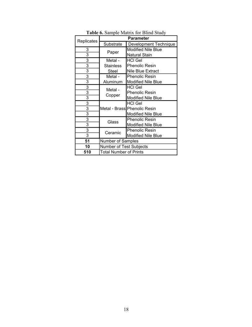
The final objective of any fingerprint development technique is to provide a high-resolution fingerprint image of sufficient integrity that can be uploaded and compared toknown databases for matching purposes. The blind study evaluated the ability of newly developed techniques to obtain a high-quality image that can be used in a commercial enrollment and comparative matching software package (VeriFinger). Tsample matrix for the blind study effort is displayed in Table 6. Each substrate andassociated development technique had three (3) replicate prints to evaluate. Each developed print wasso
17
18
Table 6. Sample Matrix for Blind Study
Substrate Development Technique3 Modified Nile Blue3 Natural Stain3 HCl Gel3 Phenolic Resin3 Nile Blue Extract3 Phenolic Resin3 Modified Nile Blue3 HCl Gel3 Phenolic Resin3 Modified Nile Blue3 HCl Gel3 Phenolic Resin3 Modified Nile Blue3 Phenolic Resin3 Modified Nile Blue3 Phenolic Resin3 Modified Nile Blue
51 Number of Samples10 Number of Test Subjects
510 Total Number of Prints
Ceramic
Replicates Parameter
Paper
Metal - Stainless
Steel
Metal - Copper
Metal - Brass
Glass
Metal - Aluminum

Section 5. Results 5.1 Porous & Non-Porous Substrate Results
Three types of non-porous surfaces were used to initially evaluate potential developers, glass, glazed ceramic, and metal. Common white copier paper was used to evaluate potential developers on porous substrates. 5.1.1 Metal Surface Etching The full procedure to produce fingerprint ridge detail using the Tek GelTM was included in Appendix A. An oily latent print, defined as a finger touched to or wiped across the forehead, was deposited on a stainless steel metal sheet approximately 2” x 2”. Initial experiments examined the use of the Tek GelTM in direct contact with the metal and within a glass chamber where the HCl was allowed to vaporize over the metal surface. All experiments were conducted in a properly vented chemical fume hood. The Tek GelTM was pipetted over the entire surface of the metal substrate in order to cover the deposited print. After twenty-four (24) hours the metal was removed from the exposure chambers and rinsed with DI water to dilute, neutralize and remove the concentrated gel product. In addition, a laboratory wipe was used to remove excess water and gently rub the metal surface to determine whether the resulting ridge patterns could be distorted by physical rubbing. Physical rubbing removes any fingerprint oils remaining on the surface. The metal covered with the Tek GelTM did not exhibit visible ridge detail. The actual acid contained in the gel does not seem to be active until evaporation causes the acidic vapors to travel over the fingerprint coated metal surface. The metal surface placed in proximity to the Tek GelTM results in clear definition of fingerprint rid
tail. Figure 12 illustrates the glass chamber setup for a TekGelTM vapor exposure. The smamount, approximately 4 mL, of fluorescent green Tek-GelTM isenough to create the ridge patteralready observed on the vertical stainless steel plate. The fingerprinis at a 45o angle on the metal surface and looks like a darkened oval. Ridge detail was captured after the metal was removed from under the glass beaker and the gel was rinse
ge de
all
n
t
d way.
Figure 12. A stainless steel plate handled by fis placed within an inverted glass beaker. A small amount of Tek GelTM is placed in the vicinity of the metal surface for 24 hours.
ingers
a
19

The chemical processing variables were examined to investigate the exposure timacquire the optimal fingerprint ridge detail. There are several variables that were considered: exposure time, chamber size, Tek GelTM mass, Tek GelTM placement in reference to the metal surface, and fingerprint type (oily versus non-oily or “unchargedExposure time was sensitive to several other conditions and constant monitoring was required to optimize the ridge detail. Twenty-four (24) hours usually resulted in a well-defined fingerprint. Figure 13 below illustrates two (2) different fingerprint types: (A) oily and (B) non-oily or uncharged. The oily fingerprint often provided a better contrast because of the differential etching caused by better metal protection with the thicker filmof secreted oils. If too much time is allowed for vapor etching, the acid begins to the metal underneath deposited oils. This lateral reaction undercut and lifted the protective
e to
”).
attack
oils from the metal, halted differential etching and eliminated established ridge atterns.
cent
d boratory nitrile gloves, goggles, and operation in a laboratory chemical fume hood.
.1.2 Phenolic Resin Dusting (Non-Porous Surfaces)
.1.2.1 Resin & Leuco Dye Preparation
p
This procedure was effective at visualizing deposited latent fingerprints on metal surfaces typically corroded by HCl vapors. The process was relatively safe because the fluoresgel was easy to see; less concentrated than typical acid etching solutions, and can be simply contained in a closed glass vessel. Proper personal protective equipment involve
Figure 13. Fingerprint ridge detail photographed after being treated for 24 hours with Tek GelTM; (A) finger coated with oils from forehead swipe and (B) finger not coated
ith oils. w
la 5 5 The phenolic resin was obtained as flakes of raw material. Phenolic resin (200 g) was ground using a mortar and pestle until a fine powder was achieved. Optimal particle sizespecifications were not established but should be prior to any commercialization effort. The crushed resin powder was applied similarly to current dusting powders. This powderwas pinkish-white in color and served as the acidic color developer that converts Leuco dyes from their uncolored structure to the colored (fluorescent) state. A one in ten (1:10)
20

dilution of Crayola® Color Wonder™ yellow paint was created by combining 5 mL of DI water and thoroughly mixing.
pment
oped
ized
a
sprayed with enough Leuco dye solution to completely wet the powder using a hand-held misting bottle. The spray was allowed to sit for one (1) minute. The sample was placed
the aqueous-based paint with 45 mL 5.1.2.2 Latent Print Develo The phenolic resin process can be applied at the crime scene and e lon-scene or back at the crime laboratory. Figure 14illustrates the steps involvedin processing latent fingerprints. The optimprotocol is included in Appendix A. Usingcommon feather fingerprint brush (Arrowhead Forensics)
ither deve
15 or a glass pipette charged with powder,the latent print was lightly dusted with powdered resin. Using compressed air, the excess resin powder was removed. The print was
Figure 14. Pictorial representation of phenolic resindusting and development: latent deposition (top left);
phenolic resin application (top right); excess resin removal (bottom left); and Leuco dye exposure (bottom right).
Figure 15. Latent prints developed with phenolic resin on glass slide (left image) and aluminum can (right image) with blue LED excitation
15 www.crime-scene.com
21

22
ng
inated with a blue LED (485 nm) and a digital image was taken with a Canon camera using an orange filter
y
ods.
the d
tive
ated that further chemical development techniques could e applied after dusting, especially those based upon amino acid fluorescent labeling
techniques such as ninhydrin.
vertically to allow excess solution to run off. Excess solution was then removed using compressed air. The sample was dried for ten (10) minutes prior to image capture. Dryiwas necessary to allow the Leuco dye to convert into the colored form by association
cidic phenolic resin dust. The processed latent print was illumwith the a
lens. Figure 15 illustrates prints developed with the resin powder technique.
Another advantage of the phenolic resin dust was its solubility in low molecular weight alcohols or in acetone. Once the dust was affixed in the latent print oils, the questioned item or surface was placed in a methanol, ethanol, or acetone vapor for a brief, usuallless than five (5) seconds, time to fix the resin onto the surface. Methanol was the best choice because it resulted in the least amount of ridge detail width change. This was tested by preparing glass slides with different line widths, optically measuring the “as-dusted” lines followed by the lines exposed to different vapors for different time periGlass slides were prepared by drawing calibrated oil lines with a plastic mask. The oil lines differed in line width from 0.25 – 2 mm. The mask was removed and the resin particles were dusted onto the oil lines. Exposure to methanol caused dissolution ofresin particles into a continuous phase that exhibited little distortion (2-5% increase) anresulted in a fixed pattern (see Figure 16). The small photo shows individual resin particles stuck in the controlled oil line prior to exposure to organic vapors. The larger photo shows the same magnification with nearly all the resin particles coalesced into a single continuous film. Methanol exhibited the least amount of width distortion relato ethanol or acetone vapors. This property allows a forensic examiner to fix the ridge detail onto a surface and protect the chemicals associated with the latent print in a polymeric coating. No tests were performed to determine if other fingerprint chemical development tests could be applied after the phenolic resin coating was fixed to the material surface. It was anticipb
Figure 16. Phenolic resin dissolution in organic solvent vapors occurs extremely rapidly. The small image is phenolic resin particles dusted onto calibrated oil lines

5.1.2.3 Fluorescent Waveguide
en
sin
mical
seen
ue allowed identifying latent rints without directly treating them with chemicals.
latent
at
by using tape lifting techniques to physically remove the print after it has een located.
.1.2.4 Additional Resin Testing
ing
phenolic resin was used. The resin instead coated all surfaces fairly evenly leaving them
Glass surfaces present a secondary option whdeciding how to process latent prints. Glass transparency allows the criminal investigator a chance at developing both glass interfaces and still visualizing the latent prints without impacting additional chemical tests or forensic investigations. As an example, the internal surface of a drinking glass can be processed with the phenolic resin; assuming that most, if not all, fingerprints will be present on the external surface. An alcoholic (isopropanol or ethanol) phenolic resin solution was sprayed onto the bottom of the glass and allowed to dry as depicted in Figure 17. The dried reforms a thin layer in intimate contact with the glass material. A solution containing the fluorescent Leuco dye was then exposed to the dried resin coating. Whenthe Leuco dye was converted to the colored cheform, it was excited with the proper excitation wavelength (blue 485 nm light produced the image in Figure 17). The resulting fluorescence emission travels down and through the glass surface due to the inherent waveguiding properties. The fluorescence was scattered when it reaches the oil components left by latent prints. The stunning visual presented in Figure 1 (Executive Summary) illustrates how effethe fluorescent waveguide was at finding difficult to find latent prints. Many of the fingerprints, ones containing low oil content, were extremely difficult to observe by simply changing the observer’s eye angle. This techniq
Figure 17. Digital photograph of individual print from beaker in Figure 1
ctive
p Careful digital photography performed at angles is required to capture images of individual prints. Figure 17 represents a focused digital photograph of one specific print recorded from the glass beaker depicted in Figure 1. There is some degree of difficulty in capturing this detailed ridge pattern on a curved surface at an angle thsufficiently refracts the emitted fluorescence. Capturing a better image would be accomplished b 5 Several other formulations and chemical processing techniques were attempted using different variations of the resin solution. The phenolic resin was dissolved in volatilesolvents such as acetone. Heated acetone with dissolved phenolic resin was used to perform fuming experiments similar to cyanoacrylate processing. No preferential coator reaction to the latent print deposits on non porous surfaces was observed when the
23

slightly sticky when handled. No follow-up chemical processing was performed to determine if the fingerprint could still be visualized by other common techniques. Another form factor common with the phenolic resin is an aqueous-based suspension. Tests were performed to determine if this liquid form exhibited preferential absorption to latent print depositions. Again it was observed that this formulation showed no preference for the latent print and instead coated the entire substrate with a sticky residue. 5.1.3 Modified Nile Blue [Nile Blue Oxazone] Treatment (Porous & Non-Porous) A modified Nile Blue formulation was successfully formulated and found to selectively associate with skin oils left on paper as well as on non-porous surfaces. Following treatment, the latent print could be visualized via bright fluorescence when excited with blue wavelengths and using an orange camera filter lens. The solution preparation and treatment process were finalized and outlined below. 5.1.3.1 Preparation of Modified Nile Blue Solution The Nile Red staining solution was prepared by dissolving the purchased Nile Blue A and isolating the Nile Red impurity in an ethyl acetate solvent phase. The detailed procedures are included in Appendix A. The isolated Nile Red fraction was then used to develop latent prints on both porous and non-porous surfaces. The Nile Red preferentially adsorbed into the fingerprint oils deposited onto the white copier paper fibers. This was the opposite phenomenon observed for the plant-derived stains that preferentially adsorbed to the paper fibers and was excluded from the fibers coated with fingerprint oils. Nile Red can also be purchased from commercial vendors without having to isolate or chemically convert the Nile Blue. During this study the Contractor found it beneficial to selectively choose between both chemicals depending upon the material color used as the background.
5.1.3.2 Latent Print Development and Image Capture Sample prints were sprayed with the 50 % DI water:50 % ethanol solution until fully wetted (5-6 sprays). A more detailed protocol was provided in Appendix A. The non-porous surface samples were kept in a horizontal position and allowed to dry (porous samples do not require drying prior to image capture). Using an orange filter and blue LED, a digital image of the developed print was captured and the captured image was imported to Adobe Photoshop for minor adjustments on an as-needed basis. If adjustment was required, typically the photo contrast was increased and it was transformed to a black and white photo. The digital image was then uploaded into the Verifinger fingerprint enrollment and identification software to verify the image quality and usability. Sample print images developed using the modified solution are presented in Figure 18. Non porous surfaces worked best for this development technique. Porous surfaces, as illustrated in the right image in , had distortion based upon some competitive dye binding to cellulosic material and the print may have been deposited on the paper substrate with too much pressure.
Figure 18
24

25
Figure 18. Latent print developed with modified Nile Blue solution on glazed ceramic (left image) and white copier paper (right image)
Some non-porous surfaces (such as metal) tested had hydrophobic surface properties and the development solution immediately beaded up instead of sheeting across the surface. In these instances the solution was unable to develop the print via spray application. Immersion of the sample prints in the solution produced some successful results on metal surfaces but vertical glass surfaces remained a challenge to the use of the Nile Blue solution. 5.1.4 Walnut Extract Treatment (Juglone) Juglone was purchased from Sigma-Aldrich (H47003; CAS# 481-39-0; 97% purity). Lawsone was also purchased from Sigma-Aldrich (H46085; CAS# 83-72-7; 97% purity). Both dye solutions were investigated and it was determined that juglone resulted in better quality digital images because the contrast resulting between dyed fibers was more apparent. Better contrast for juglone was observed with and without mordanting with iron sulfate when compared with lawsone-treated exemplars. The juglone solution was used for the stability study and the blind comparison testing. 5.1.4.1 Solution Preparation A saturated aqueous solution of juglone was prepared with the purchased raw chemical. Chemical dissolution was aided by heating the water at 60oC for thirty (30) minutes.
5.1.4.2 Latent Print Treatment
A small amount of (~ 5 mL) of 5-hydroxy-1,4-naphthoquinone (juglone) solution was placed into an appropriately-sized Petri dish for the samples to be developed. Sample white copier paper containing a latent print was placed in the Petri dish, ensuring the paper was completely immersed in solution (juglone solution was added as needed). Paper was soaked in the juglone solution for ten (10) minutes. Using forceps sample paper was placed on a dry chemical wipe, and then placed into an oven set at 70°C for ten

(10) minutes. Samples were removed and allowed to cool to ambient temperature for three (3) hours. A small amount (5 mL) of iron sulfate solution (5 mM) was then poured into another Petri dish; paper was placed into the dish again, ensuring the paper was completely immersed in solution. Juglone-treated paper was soaked in iron solution for ten (10) minutes, followed by air drying for a minimum of sixty (60) minutes. Using a glass pipette, DI water was dripped onto the paper corners and allowed to wick through the paper, visualizing the latent print. The paper sample was kept moist, placed on a light table for back-lighting and photographed. Figure 19 illustrates the visualization process for the juglone-treated porous material. The first two photos illustrate the ridge appearance as the paper surface becomes wetted by water treatment. The ridge detail is observed most clearly at the outer regions of the deposited print. This is most likely due to the paper fiber absorbance that causes ridge distortion in areas where the finger was held more strongly to the material. The fingerprint detail disappears as the paper dries, but the observation can be repeated over and over by re-moistening the paper. The last photo shows how iron exposure caused a color change and resulted in slightly better contrast between the shades of grey in photos A and B and orange versus white in photo C. The image in photo C is also observed only when the paper fibers are wetted.
Figure 19. Digital photographs of juglone-treated white copier paper: (A) water exposure, (B) zoomed-in photo of A, and (C) after iron mordant process
5.1.5 Osage Orange Treatment The Osage Orange leachate, prepared by extracting a dye mixture from tree bark, exhibited similar staining properties as the juglone and lawsone isomers. The Osage Orange mixture also had inherent fluorescence that could be more sensitive to fingerprint ridge detail. Mordant exposure quenched the inherent fluorescence present on the stained fiber while leaving Osage Orange dye fluorescence intact when the dye was absorbed into the print oils. Unfortunately, this effect could not be reproduced because the mordant process was extremely sensitive to exposure time. If the mordant process was not done for enough time it resulted in unresolved ridge detail due to interfering background fluorescence and if performed too long all fluorescence was quenched. 5.1.5.1 Solution Preparation Osage Orange extracts were prepared by boiling the bark from the Osage Orange tree for several hours. The resultant solution was then filtered through a cheese cloth to remove
26

all particulates from the extraction process. Detailed steps were provided in Appendix A explaining the Osage Orange solution preparation. 5.1.5.2 Latent Print Treatment A small amount of (~ 5 mL) the Osage Orange leachate solution was placed into an appropriately-sized Petri dish for the samples to be developed. Sample white copier paper containing a latent print was placed in the Petri dish, ensuring the paper was completely immersed in solution. Paper was soaked in the leachate solution for ten (10) minutes. Using forceps sample paper was placed on dry chemical wipe, and then placed into an oven set at 70°C for ten (10) minutes. Samples were removed and allowed to cool to ambient temperature for three (3) hours. A small amount (5 mL) of iron sulfate solution (5 mM) was then poured into another Petri dish; paper was placed into the dish again, ensuring the paper was completely immersed in solution. Leachate-treated paper was soaked in iron solution briefly (usually less than five (5) seconds, followed by air drying for a minimum of sixty (60) minutes. The critical timing element of iron sulfate exposure required observing the process under the fluorescence emission wavelength to halt exposure before ridge detail is lost. As the fluorescence is quenched and the ridge detail appears, the paper is quickly removed from the iron solution and immediately exposed to pure water to stop the mordant process. The ridge detail could then be viewed after the paper was dried for sixty (60) minutes. Figure 20 illustrates the effect when the mordant process is halted at the appropriate time. Some background fluorescence is still present leading to the spottiness in some areas within the fingerprint image and this could be due either to incomplete mordanting or ridge broadening due to paper fiber absorbance.
Figure 20. Ridge detail enhanced by fluorescence after background paper fiber fluorescence quenched by mordant process
5.2 Stability Study Results The stability study evaluated the effects of various common environmental conditions on the ability of the newly formulated development techniques to successfully visualize latent prints. The sample naming scheme for the stability study is indicated in Table 7. Each sample was assigned a unique identifier used to determine the exact conditions in which each sample was stored. Detailed test plans and procedures were written for the stability study and were included as Appendix C.
27

Table 7. Stability Study Sample Naming Scheme
Test Substrate Time Point
Humidity Level Temperature UV Exposure Replicate
S - Stability
G - Glass 0 - 0 day H – 75% E – 45°C L - UV 1 P - Paper 1 - 1 day L - <5% A – Ambient D – No UV 2
2 - 2 day
C – 5°C
3 3 - 1 week
4 - 2 weeks 5 - 4 weeks
The images successfully enrolled into the VeriFinger recognition software for the non-porous substrate developed using the phenolic resin powder technique are presented in Table 8. Triplicate samples were developed for each environmental condition at each time point totaling thirty (30) latent prints for each time point and one hundred fifty (150) latent prints for each condition evaluated. The three (3) letter condition code is located in the far left column and corresponds to the naming scheme provided in Table 7. For example, condition “HAL” corresponds to storage in High humidity, Ambient temperature, and UV Light. In addition, three (3) samples were created as “0” day controls. All three of the 0-day samples were accepted by the recognition software. 0-day print examples are shown in Figure 22 and Figure 21.
Table 8. Non-Porous Stability Study Images Successfully Enrolled at Each Time Point and Environmental Condition
Condition Day 1 Day 2 Week 1 Week 2 Week 4 Total Viable Prints
HAL 3 1 3 2 0 60% HAD 3 1 2 2 0 53% HEL 2 0 0 1 0 20% HED 1 1 1 0 0 20% LAL 3 3 3 2 3 93% LAD 1 2 2 1 3 60% LCL 3 2 2 0 1 53% LCD 2 2 3 2 3 80% LEL 2 3 1 1 1 53% LED 0 2 2 0 0 27%
28

Figure 22. Day 0 Stability Print Developed with Resin
The total percent of non-porous stability study images developed and accepted by VeriFinger software over time is shown in Figure 23. As expected, the ability to develop and successfully import latent prints decreases over time as the prints degrade. As discussed above, the environmental conditions varied and played a distinct role in the ability to develop the prints. The non-ambient conditions evaluated represented the most extreme exposure scenarios; therefore the percentages of prints sucessfully enrolled should not be taken as hard values for real-time print development, but rather included as
an indication of the likelihood of successful print development in long-term and extreme circumstances.
Figure 21. Day 0 Stability Print after Photoshop Enhancement
5.3 Blind Study Results
Figure 23. Percent of Non-Porous Substrate Images Accepted by Fingerprint Recognition Software by Time Point
29

Figure 24 separates the print enrollment statistics for each environmental factor tested. The two (2) worst environmental conditions involve high humidity and high temperature (red bars indicate lower than 20 % acceptance). The two (2) best environmental conditions involve low humidity (dark green bars indicating > 80 % acceptance). Moderate temperatures (room temperature) with high or low humidity result in software-recognizable prints more than half the time.
Figure 24. Enrolled Percentage of Fingerprints Based Upon Environmental Treatment
5.4 Blind Study Results The sample naming scheme for the blind study effort is displayed in Table 9. Each substrate and associated development technique had a unique sample identifier assigned. Detailed test plans and procedures were written for the stability and blind studies and were included as Appendix C.
30

Table 9. Blind Study Sample Naming Scheme
Test Substrate Development Technique Participant # Replicate
B - Blind Study
G - Glass H - HCl Gel 01 1 C - Ceramic R - Phenolic Resin 02 2
P - Paper N - Nile Blue 03 3 A - Aluminum J - Juglone 04
S - Stainless Steel
05
Cu - Copper 06 Br - Brass 07
08 09 10
None of the juglone-treated paper samples resulted in print images that could be enrolled with the VeriFinger software. The difficulty was digitally photographing the fingerprint image after exposure to obtain the proper contrast between dyed and un-dyed paper fibers. One way to overcome the technical difficulties might be to backlight the paper substrate to improve the color contrast. Juglone also shows promise as a candidate to chemically react with the amino acids present in the fingerprint residues. The recent research article with lawsone suggests juglone, a structural isomer, could also be used in a similar manner4. At the time of this work, the Contractor did not have access to either the illumination wavelength or the camera filters to investigate the fluorescent properties associated with coupling the lawsone or juglone with amino acid residues. The metal substrates treated with the HCl gel were etched all together in one large exposure chamber. The large substrate number prevented precise control of the etching process. Longer development times were required and the resulting fingerprint images varied too much for a large-scale study of the image processing stage of the blind study. Some samples resulted in well resolved ridge detail while others were badly over etched. The badly over etched substrates often resulted in an overall oval pattern to indicate the location of the general finger shape but all internal ridge detail was lost. In the future, metal items should be individually processed to conduct a more controlled etching. Also, fingerprint images performed on metal require careful lighting to produce images that can be imported into the VeriFinger software. The only items that could be processed in the blind study included the ceramic and paper surfaces treated with the modified Nile Blue solution, and the ceramic, aluminum metal, and glass treated with the fluorescent phenolic resin. Table 10 presents the blind study results from the treated surfaces that could be processed with the VeriFinger software. The biggest difficulty came in capturing digital photographs that could be properly formatted to allow the VeriFinger software to successfully upload. The software package was specifically targeted for electronic fingerprint scanners. Significant image processing steps were followed in order to import files that could be extracted for comparison. The steps included converting the raw color image file into a black and white and adjusting
31

32
the threshold levels, reducing dpi resolution, converting to a tiff file format, and then importing into the software. The ceramic surface provided the best chance for a digital photograph to be successfully uploaded. However, even a successful upload did not guarantee a positive match with any of the enrolled subjects. The VeriFinger software successfully matched developed fingerprints at close to a 50 % frequency. The match probability was low due to the image processing steps involved as well as unfamiliarity with the fingerprint matching algorithm. No false positive matches were made. When the software uploaded and identified a latent print match – the match was the correct identification. More work will be required to process latent prints in order to use the software algorithms and tools to accurately identify electronic-derived (fingerprint scanner) or scanned fingerprint card images with digital images captured via camera.

Table 10. Blind Study Results
# of Possible Images
# of Accepted Images
Images Accepted
1 2 3 4 5 6 7 8 9 10Matched Images
Matching Percentage
False Positives
Nile Blue Ceramic Altered 30 27 90.0% 0/3 3/3 2/3 0/3 0/3 1/3 1/3 1/1 2/3 1/2 11 40.7% 0.0%Nile Blue Paper Altered 30 12 40.0% 0/1 1/2 0/1 0/0 0/2 3/3 0/0 0/0 2/3 0/0 6 50.0% 0.0%Nile Blue Aluminum 30Nile Blue Copper 30Nile Blue Brass 30Nile Blue Stainless Steel 30Nile Blue Glass 30. 6Resin Ceramic Altered 30 25 83.3% 0/3 0/2 0/2 0/3 0/3 2/3 0/1 2/2 2/3 0/3 6 24.0% 0.0%Resin Glass Altered 30 13 43.3% 0/1 0/0 0/0 1/1 1/3 1/2 0/1 0/2 2/3 0/0 5 38.5% 0.0%Resin Aluminum Altered 30 16 53.3% 0/0 2/3 2/3 1/1 0/3 2/2 0/0 0/1 1/3 0/0 8 50.0% 0.0%Resin Copper Altered 30Resin Brass Altered 30Resin Stainless Steel Altered 30
‐‐ ‐‐ ‐‐ ‐‐
‐‐ ‐‐‐‐‐‐ ‐‐ ‐‐
‐‐ ‐‐
33

34
Section 6. Conclusions and Path Forward
6.1 Conclusions Overall, MRI has developed three (3) new latent print development techniques that are less hazardous than existing methods and have several additional techniques with successful proof-of-concept work completed. The modified Nile Blue formulation produces high-quality prints on multiple non-porous surfaces as well as on paper. The Nile Blue solution has the distinct advantage of converting completely to a fluorescent orange moiety that can provide greater contrast if the background substrate color is too similar to the initial dark blue hue. The Nile Blue mainly stains the lipid portion of the fingerprint deposit. No heat treatment is necessary and the solution can be applied as a spray and rinsed to remove excess. The Leuco dye/phenolic resin technique produces high quality prints on any non-porous surface when used as a replacement to traditional dusting powders. The phenolic resin can be used as a white dusting powder or can be modified with different Leuco dyes. The flexibility allows any color or fluorescent wavelength to be chosen to provide greater contrast from the background color. The resin can also be fused to substrates with volatile organic vapors. The result is a tough coating that protects the fingerprint ridge detail from damage. At this time it is not known whether this coating can be further processed with traditional chemical development techniques. The greatest advantage of this specific processing occurs if the latent print is found on glass. The treatment can be used without altering the print by using the optical waveguide properties of the glass. The fluorescence emission travels through and along the glass surfaces to visualize faint prints that are not visible. This allows a forensic examiner to obtain prints without any destructive chemical processing. The HCl gel etching technique produces high-quality prints on stainless steel surfaces. This acidic vapor etching has been performed in the past but with highly corrosive liquids that involve some safety concerns. The HCl gel is a much safer COTS product that reduces the risk of chemical exposure by diluting the corrosive in a brightly-colored gel matrix. As the HCl vapor is slowly released from the gel material, the differential etching produces the ridge detail on the metal surface. Due to the nature of the highly corrosive vapors involved, it is recommended that this chemical processing be one of last resort. It is unlikely that traditional chemical processing will be successful after this treatment. The two (2) natural dye techniques developed for use on porous surfaces show promise and are currently able to visualize prints on common copy paper, but more contrast is needed in order to produce a fully usable print that can be captured with a high-resolution digital camera. These early-stage studies did not involve fingerprint examiners because there is still additional work that is required before any of these techniques could supplant the traditional fingerprint chemical development processes. 6.2 Path Forward Fingerprint development techniques within the crime scene laboratory are very mature. None of the developed techniques of this study are ready for the forensic community at this time. The main objective to identify a ready-to-use crime scene fingerprint spray was not realized during
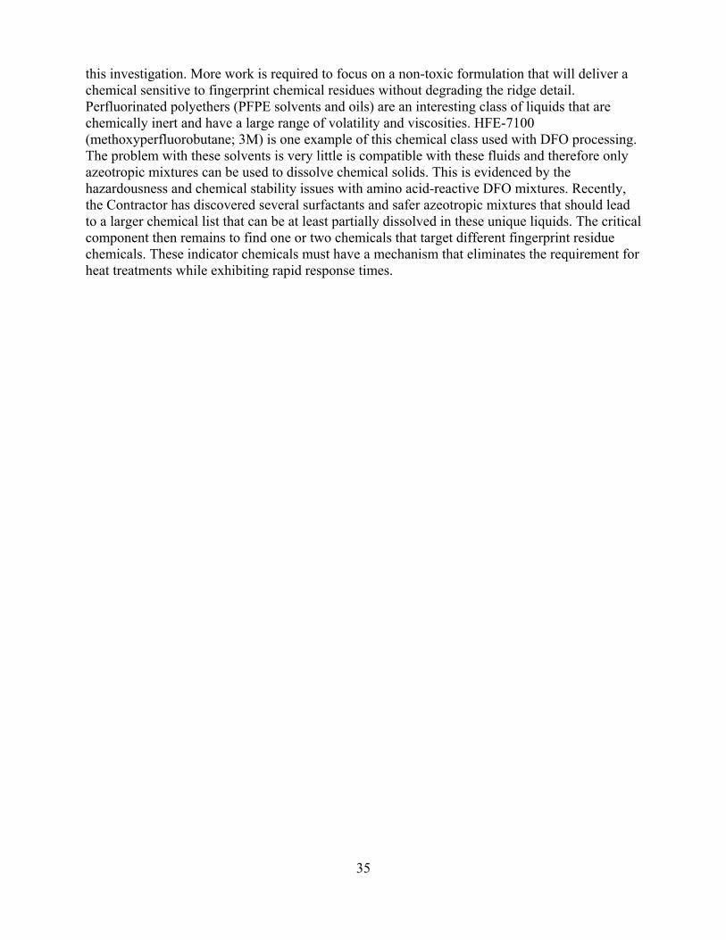
this investigation. More work is required to focus on a non-toxic formulation that will deliver a chemical sensitive to fingerprint chemical residues without degrading the ridge detail. Perfluorinated polyethers (PFPE solvents and oils) are an interesting class of liquids that are chemically inert and have a large range of volatility and viscosities. HFE-7100 (methoxyperfluorobutane; 3M) is one example of this chemical class used with DFO processing. The problem with these solvents is very little is compatible with these fluids and therefore only azeotropic mixtures can be used to dissolve chemical solids. This is evidenced by the hazardousness and chemical stability issues with amino acid-reactive DFO mixtures. Recently, the Contractor has discovered several surfactants and safer azeotropic mixtures that should lead to a larger chemical list that can be at least partially dissolved in these unique liquids. The critical component then remains to find one or two chemicals that target different fingerprint residue chemicals. These indicator chemicals must have a mechanism that eliminates the requirement for heat treatments while exhibiting rapid response times.
35
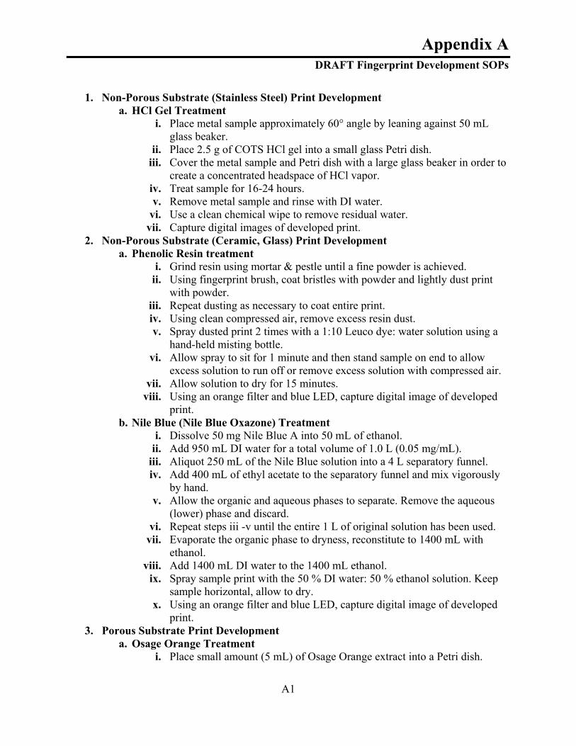
A1
Appendix A DRAFT Fingerprint Development SOPs
1. Non-Porous Substrate (Stainless Steel) Print Development
a. HCl Gel Treatment i. Place metal sample approximately 60° angle by leaning against 50 mL
glass beaker. ii. Place 2.5 g of COTS HCl gel into a small glass Petri dish.
iii. Cover the metal sample and Petri dish with a large glass beaker in order to create a concentrated headspace of HCl vapor.
iv. Treat sample for 16-24 hours. v. Remove metal sample and rinse with DI water.
vi. Use a clean chemical wipe to remove residual water. vii. Capture digital images of developed print.
2. Non-Porous Substrate (Ceramic, Glass) Print Development a. Phenolic Resin treatment
i. Grind resin using mortar & pestle until a fine powder is achieved. ii. Using fingerprint brush, coat bristles with powder and lightly dust print
with powder. iii. Repeat dusting as necessary to coat entire print. iv. Using clean compressed air, remove excess resin dust. v. Spray dusted print 2 times with a 1:10 Leuco dye: water solution using a
hand-held misting bottle. vi. Allow spray to sit for 1 minute and then stand sample on end to allow
excess solution to run off or remove excess solution with compressed air. vii. Allow solution to dry for 15 minutes.
viii. Using an orange filter and blue LED, capture digital image of developed print.
b. Nile Blue (Nile Blue Oxazone) Treatment i. Dissolve 50 mg Nile Blue A into 50 mL of ethanol.
ii. Add 950 mL DI water for a total volume of 1.0 L (0.05 mg/mL). iii. Aliquot 250 mL of the Nile Blue solution into a 4 L separatory funnel. iv. Add 400 mL of ethyl acetate to the separatory funnel and mix vigorously
by hand. v. Allow the organic and aqueous phases to separate. Remove the aqueous
(lower) phase and discard. vi. Repeat steps iii -v until the entire 1 L of original solution has been used.
vii. Evaporate the organic phase to dryness, reconstitute to 1400 mL with ethanol.
viii. Add 1400 mL DI water to the 1400 mL ethanol. ix. Spray sample print with the 50 % DI water: 50 % ethanol solution. Keep
sample horizontal, allow to dry. x. Using an orange filter and blue LED, capture digital image of developed
print. 3. Porous Substrate Print Development
a. Osage Orange Treatment i. Place small amount (5 mL) of Osage Orange extract into a Petri dish.

ii.
2
Place paper with latent print into dish, print side down, ensuring the paper is completely immersed in the solution.
iii. Allow paper to soak in solution for 10 minutes. iv. Place sample in oven set at 60°C for 10 minutes. v. Soak paper in DI water print side down, until 100% wet (~5 sec).
vi. Place paper on chemwipe and allow to air dry for 1 hour. vii. Place small amount (5 mL) of 5 mM iron solution in Petri dish.
viii. Dip paper, print side up into iron solution for 1 second. ix. Dip Iron side of paper into DI water for 2 seconds. x. Dip Osage Orange side of paper into DI water for 1 second.
xi. Place paper on a chemical wipe. xii. Capture digital image of developed print.
b. Juglone Treatment i. Place small amount (5mL) of 5-hyroxy-1,4 naphthoquinone into a Petri
dish. ii. Place paper with latent print into dish, ensuring the paper is completely
immersed in solution. iii. Allow paper to soak in solution for 10 minutes. iv. Using forceps place sample paper on dry chemwipe. v. Place sample in oven set at 70°C for 10 minutes.
vi. Allow sample to cool to ambient temperature for 3 hours. vii. Place small amount (5mL) of Iron solution (5mM) in a Petri dish.
viii. Place paper into dish, ensuring paper is completely immersed in solution. ix. Allow paper to soak in solution for 10 minutes. x. Allow paper to air dry for at least 60 min.
xi. Using a glass pipette, drip DI water on the corners of the paper and allow water to wick through paper, visualizing latent print.
xii. Capture image using digital camera.

Appendix B
MSDS
B1

Appendix C Stability Study
Attachment #1 Fingerprint Studies Test Procedure (TP)
File Name: Fingerprint Studies TP.doc
WBS 4.0
Project 110636
Date: September 1, 2009

C2
Section 1. Procedure 1.1 Scope This document describes the test procedure necessary to execute the Fingerprint Stability Study as well as the blind study in accordance with the approved test plan. As a stand-alone document, this test procedure provides a step-by-step description of laboratory actions necessary to test objectives stated in the TPPS. 1.2 Applicable Documents The following documents, of the revision shown, form a part of this document to the extent specified. If a revision number is not shown, then it is the issue in effect on the date of this document. In the event of a conflict between this document and the contents of one of the documents listed below, this document shall take precedence. The following documents can be found on the MRI internal network or in the MRI Project Folder for 110636.
Table 1. Applicable Documents
Document Number Document Name Revision Date SOP MRI-0020 Labeling Requirements 3 17 Nov 2005 MRI CHP Chemical Hygiene Plan 8 24 Oct 2007 SOP MRI-0001 Corrective and Preventive Action 5 29 Feb 2008 SOP MRI-0003 Control of Nonconforming Product 2 21 Dec 2007
1.3 Quality Assurance Provisions This document is under revision control at MRI and shall be updated as needed during the Fingerprint Stability Study test execution. Control of revisions to this document and subsequent redistribution shall be per SOP MRI-0001 and SOP MRI-0003. This procedure shall be executed in sequential order in accordance with the steps as described in this document. Any deviation to the steps, or the order that they are executed, shall be documented at the point they occurred and signed by the Operator. These deviations, along with the step execution signatures and data recording, form the As-Run procedure. Deviations shall be categorized as major or minor. Major deviations are those that affect cost, schedule, or technical objectives. All other deviations are defined as minor. The principle investigator (PI) shall be notified, and approval received, prior to proceeding past the point a major deviation occurred. Minor deviations shall be reported to the PI within one (1) business day. However, PI approval to proceed past the point a minor deviation occurred is not required.

C3
1.4 Personnel Qualifications This procedure shall be performed by MRI personnel that have been adequately trained for the steps to be performed. This training includes, but is not limited to, the appropriate operating, safety, and quality procedures. Additionally, MRI personnel must receive approval by the PI prior to working on this test. Due to the varying range of qualifications required to perform the individual test procedures described in this document, the required minimum personnel qualifications are described at the front of each procedure when applicable. 1.5 Safety All procedures shall be performed in accordance with MRI safety procedures as documented in the MRI Chemical Hygiene Plan (CHP). Specific safety requirements, where applicable, are described at the front of each test procedure module. 1.6 Waste Management All waste shall be disposed in accordance with SOP MRI-5900. Specific waste management requirements, where applicable, are described at the front of each test procedure module and/or SOP. 1.7 Materials The following is a list of materials required to execute this top level test procedure. Please refer to the TPPS for a list of manufacturers and part numbers if needed.

Table 2. Materials for Top Level Procedure
C4
Item As-Run Quantity
Black Ceramic Tile 60 Aluminum cans 60 Glass Sample Slides 153 Stainless Steel Squares 90 Copper Squares 90 Brass Squares 90 Common copy paper squares 60 Osage Orange solution 500 mL Juglone/Lawsone solution 500mL Phenolic Resin 250g Leuco Dye 120mL Nile Blue Extract Stain 500mL HCl Gel 1 Bottle DI water 10L Acetone 1L Methanol 1L Isopropanol 1L Drinking Glasses 60 High-Resolution Digital Camera 1 Digital Persona Fingerprint Scanner 1 Crayola Color-Wonder Paint & Paper 1 set Iris Business card scanner 1 Iron (3) Solution 500 mL Aluminum Foil 1 roll Dessicator 6 Small Oven 1 Small environmental chamber 1 Walk-in environmental chamber 1 1 L Glass Beaker 3 UV Light 5 Verifinger Software 1 license
1.8 Overview This test plan describes the procedures to complete the Fingerprint Stability Study and the Blind Study. The steps shall be executed in sequential order as described. Each step shall be initialed and dated upon completion by the Operator or Witness. The forms provide additional details and steps to be followed. 1.9 Procedures The following steps shall be sequentially executed as described. Each step shall be initialed and dated upon completion by the operator or witness.

Table 3. Test Procedures
C5
Step # Operation Initial/Date Solution Preparation
1 Prepare Osage Orange Solution 2 Prepare Juglone/Lawsone Solution 3 Prepare Iron (3) Solution 4 Prepare Leuco dye solution 5 Place Leuco dye solution in plastic spray bottles. 6 Prepare Nile Blue solution
Stability Study
7 Deposit 150 prints on glass sample slides. Between each print, touch finger to forehead (do not rub forehead).
8 Deposit 150 prints on pre-cut squares of common copy paper. Between each print, touch finger to forehead (do not rub forehead).
9 Place 30 sample prints (15 glass & 15 paper) in each of six (6) dessicators.
10 Place 2 dessicators in a refrigerator at 5°±5°C. Completely wrap one (1) dessicator in aluminum foil to ensure no light can enter the dessicator. Place a UV light inside the fridge to remain on at all times.
11 Place 1 dessicator on a laboratory bench top at ambient temperature (20°±5°C). Wrap the dessicator in aluminum foil in order to ensure no light can enter the dessicator.
12 Place 1 dessicator inside a laboratory drawer at ambient temperature (20° ±5°C). Position a UV light inside the drawer so the samples are exposed at all times.
13 Place 2 dessicators in a small oven at 45°±5°C. Completely wrap one (1) dessicator in aluminum foil to ensure no light can enter the dessicator. Place a UV light inside the oven to remain on at all times.
14 Place 60 sample prints (30 glass & 30 paper) in the walk-in Chamber set at 45°C ±5° and 75% ± 5% humidity. Of the 30 of each substrate, cover 15 with aluminum foil so no light can get to the samples. Install a UV light inside the chamber.
15
Place 60 sample prints (30 glass & 30 paper) in the small chamber at ambient temperature (20°±5°C) and 75% ± 5% humidity. Of the 30 of each substrate, cover 15 with aluminum foil so no light can get to the samples. Position a UV light so the samples are exposed at all times.
16 Record start time for each condition in laboratory notebook.
17 Deposit 3 prints on common copy paper, and 3 prints on glass sample slides. Process the six (6) day “0” prints per developed methods. Record methods in laboratory notebook. Take several digital photographs of each result
18 After 24 hours in the various conditions, remove 3 paper and 3 glass samples from each condition (60 total samples = 10 conditions x 2 substrates x 3 replicates).
19 Process each sample per developed methods and take several digital photographs of each result.
20 After 48 hours in the various conditions, remove 3 paper and 3 glass samples from each condition (60 total samples = 10 conditions x 2 substrates x 3 replicates).
21 Process each sample per developed methods and take several digital photographs of each result that give multiple views of each print.
22 After 1 week (7 days) in the various conditions, remove 3 paper and 3 glass samples from each condition (60 total samples = 10 conditions x 2 substrates x 3 replicates).
23 Process each sample per developed methods and take several digital photographs of each result.
24 After 2 weeks (14 days) in the various conditions, remove 3 paper and 3 glass samples from each condition (60 total samples = 10 conditions x 2 substrates x 3 replicates).
25 Process each sample per developed methods and take several digital photographs of each result.
Blind Study 26 Obtain 10 voluntary participants and collect their fingerprints electronically (via Digital
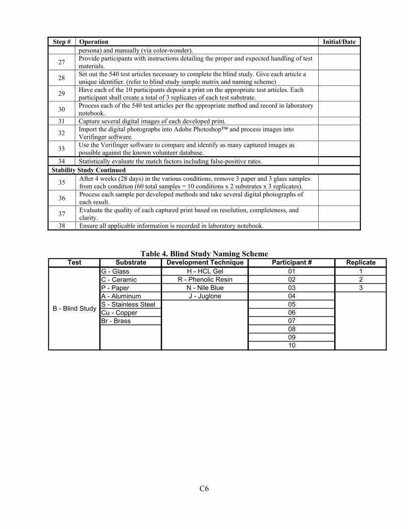
C6
Step # Operation Initial/Date persona) and manually (via color-wonder).
27 Provide participants with instructions detailing the proper and expected handling of test materials.
28 Set out the 540 test articles necessary to complete the blind study. Give each article a unique identifier. (refer to blind study sample matrix and naming scheme)
29 Have each of the 10 participants deposit a print on the appropriate test articles. Each participant shall create a total of 3 replicates of each test substrate.
30 Process each of the 540 test articles per the appropriate method and record in laboratory notebook.
31 Capture several digital images of each developed print.
32 Import the digital photographs into Adobe Photoshop™ and process images into Verifinger software.
33 Use the Verifinger software to compare and identify as many captured images as possible against the known volunteer database.
34 Statistically evaluate the match factors including false-positive rates. Stability Study Continued
35 After 4 weeks (28 days) in the various conditions, remove 3 paper and 3 glass samples from each condition (60 total samples = 10 conditions x 2 substrates x 3 replicates).
36 Process each sample per developed methods and take several digital photographs of each result.
37 Evaluate the quality of each captured print based on resolution, completeness, and clarity.
38 Ensure all applicable information is recorded in laboratory notebook.
Table 4. Blind Study Naming Scheme Test Substrate Development Technique Participant # Replicate
G - Glass H - HCL Gel 01 1C - Ceramic R - Phenolic Resin 02 2P - Paper N - Nile Blue 03 3A - Aluminum J - Juglone 04S - Stainless Steel 05Cu - Copper 06Br - Brass 07
0809
B - Blind Study
10

Table 5. Stability Study Naming Scheme
C7
Test Substrate Time Point Humidity Level Temperature UV
Exposure Replicate
S - Stability
G - Glass 0 - 0 day H – 75% E – 45°C L - UV 1 P - Paper 1 - 1 day L - <5% A – Ambient D – No UV 2
2 - 2 day
C – 5°C
3 3 - 1 week
4 - 2 weeks 5 - 4 weeks

Test Conductor Notes and Observations:
C8
________________________________________________________________________________________________________________________________________________________________________________________________________________________________________________________________________________________________________________________________________________________________________________________________________________________________________________________________________________________________________________________________________________________________________________________________________________________________________________________________________________________________________________________________________________________________________________________________________________________________________________________________________________________________________________________________________________________________________________________________________________________________________________________________________________________________________________________________________________________________________________________________________________________________________________________________________________________________________________________________________________________________________________________________________________________________________________________________________________________________________________________________________________________________________________________________________________________________________________________________________________________________________________________________________________________________________________________________________________________________________________________________________________________________________________________________________________ Anomalies/Difficulties: ____________________________________________________________________________________________________________________________________________________________________________________________________________________________________________________________________________________________________________________________________________________________________________________________________________________________________________________________________________________________________________________________________________________________________________________________________________________________________________________________________________________________________________________________________________________________________________________________________________________________________________________________________________________________________________________________________________________________________________________________________________________________________________________________________________________________________________________________________________________________________________________________________________________________________________________________________________________________________________________________________________________________________________________________________________________________________________________________ ______________________________________________________________________________

Attachment I IRB Request Form

Attachment II 1
Attachment II Informed Consent Letter
MIDWEST RESEARCH INSTITUTE
425 Volker Boulevard, Kansas City, MO 64110-2299 VOLUNTEER’S INFORMED CONSENT
Latent Print Chemical Visualization I, ___________________________________________________________________residing at ______________________________________________________________________________ hereby acknowledge and certify to the following:
1. You are being invited to voluntarily participate in a research study sponsored by Midwest Research Institute (MRI) at the MRI-Kansas City, MO division by Dr. James M Egan. This study will attempt to determine if specific, non-toxic chemical treatment of latent prints on different common material surfaces can be visualized. Samples collected will involve common fingerprinting techniques used in law enforcement. All chemicals used for fingerprint enrollment are considered non-toxic (wax formula and coated paper used for enrollment phase, steps i and ii) and meet ASTM D4236 Standards: Standard Practice for Labeling Art Materials for Chronic Health Hazards. Anyone who has a chemical sensitivity or sensitive skin may develop an allergic reaction.
a. Enrollment Phase will include: i. Pressing fingertips into a non-toxic wax formula
ii. Pressing coated fingertips to non-toxic, coated paper surface iii. Transfer will result in a colored fingerprint image
b. The second study phase, Forensic Phase, involves handling common material substrates:
i. Fingers will be rubbed against participant’s forehead to transfer sweat ii. Handle various materials such as glass, paper, metal, plastic, ceramic,
and wood surfaces with sweaty fingerprints
2. Participants may choose to donate during the enrollment phase, during the forensic phase, or during both periods.
3. Potential Risks and Discomforts: There are no known health or safety risks for the fingerprint sample collection described above.
4. Anticipated Benefits to Participants: This is a basic research study, and volunteers
will not derive any direct personal benefit from being in it other than knowing that he/she has helped contribute to the progress of science. Preliminary data

derived from this project will be applied toward demonstration of proof-of-principle to, and obtaining funding from, the forensic community.
Attachment II 2
5. All questions from research volunteers will be answered fully and promptly by Dr.
James M Egan, Principal Investigator, or by Jeff Shular, Chairman of the MRI Institutional Review Board for Human Studies, which reviewed and approved this study (816-360-5414). The address of the Institute is 425 Volker Boulevard, Kansas City, MO 64110.
6. Volunteers have the right to withdraw consent and to stop participating in this study
at any time without prejudice, regardless of the status of the study and regardless of the effect of such withdrawal on the objectives and results of the study. Participation in the study may also be stopped at any time by the investigators in charge of the project.
7. Each sample will be affixed with a unique identifier (a three-digit number followed
by a hyphen followed by a number from 1-10 identifying all fingerprint positions for each subject; e.g. 123-1 [left pinkie], 123-2 [left ring finger], …) by the principal investigator, or his designee. The identifier will have no traceability to the identity of the volunteer. The identifier will be the only information associated with the sample. Information and data obtained through this study will have no traceable connection to any volunteer. By participating, you agree that MRI may utilize any information obtained by MRI or its authorized representatives in the course of the study in publications and reports that will not personally identify individuals.
8. MRI is responsible for this research project. If a volunteer is injured as a direct
result of his/her participation in this research project, medical care will be provided, at no cost, for that injury. Only medical care, and not injury compensation, will be provided. This is not a waiver or release of a volunteer's legal rights. This issue should be discussed thoroughly with the Principal Investigator before enrolling in this study. Other than the medical care that may be provided (and the other benefits stated above in paragraph 3 of this consent form), there is no compensation available for participation in this research study.
I have been informed of the nature, duration, and purpose of the study, the means by which the study will be conducted, and possible inconveniences, hazards, discomfort, risks, and adverse effects on my health which could result from my participation. There will be no cost to me for participation in the study. I voluntarily agree to participate and have been informed that I can withdraw from participation in this study at any time without penalty.

I will be given a copy of this consent form to keep.
Attachment II 3
I am executing this Volunteer's Consent as my free act and deed.
Volunteer:
_____________________ _____________________________ Date: ________ Printed Name Signature
Investigator or designee:
_____________________ _____________________________ Date: ________ Printed Name Signature

Attachment III Fingerprint Collection Protocol
Human Subjects Fingerprint Collection, Enrollment, and Latent Deposition Study Protocol 1.0 Scope Twenty (20) volunteers will be asked to provide their fingerprints for a study involving latent print chemical development. There are no specific limitations or requirements that a volunteer must meet to participate in this study. Chemical development is a process used by forensic investigators to visualize fingerprints left behind at crime scenes. This document describes the procedure for obtaining volunteer fingerprints [COLLECTION], entering them into an electronic database [ENROLLMENT], and directing the volunteers to intentionally leave fingerprints on known objects and locations for subsequent chemical development [LATENT DEPOSITION]. 2.0 Applicable Documents The documents listed in the following table are incorporated by reference into this protocol, to the extent specified. In the event of a conflict between the Study Protocol and the contents of the documents listed below, this document shall take precedence. The Chemical Hygiene Plan can be found on the MRI internal network.
Document Number
Title Location
MRI CHP Chemical Hygiene Plan - Informed Consent Letter 110636 Project Folder - Institutional Review Board Approval 110636 Project Folder
P81379_final Latent Chemical Print Development Final Proposal
110636 Project Folder
NIJ Contract_2008-NI-CX-K012
Official Contract 110636 Contract Folder
- 814379 NEPA-chemical list 110636 Project Folder EA-2008-NI-CX-K012
Environmental Assessment 110636 Project Folder
- Belmont Report MRInet 45 CFR 46 Federal Policy for the Protection of Human
Subjects http://hhs.gov/ohrp/humansubjects/g
uidance/45cfr46.htm#46.116 - NIH/OHRP Human Subject Assurance
Training http://ohrp.osophs.dhhs.gov/humans
ubjects/guidance/certconpriv.htm SOP MRI-900 Human Subjects Research Overview MRInet SOP MRI-901 IRB Membership MRInet SOP MRI-902 Institutional Review Board Meetings MRInet SOP MRI-903 Initial IRB Review of Proposed Studies MRInet SOP MRI-904 Continuing IRB Review of Research Studies MRInet SOP MRI-905 Expedited IRB Review of Proposed MRInet
Attachment III 1
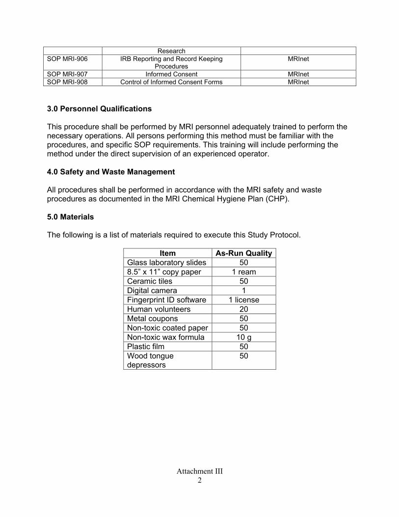
Research SOP MRI-906 IRB Reporting and Record Keeping
Procedures MRInet
SOP MRI-907 Informed Consent MRInet SOP MRI-908 Control of Informed Consent Forms MRInet 3.0 Personnel Qualifications This procedure shall be performed by MRI personnel adequately trained to perform the necessary operations. All persons performing this method must be familiar with the procedures, and specific SOP requirements. This training will include performing the method under the direct supervision of an experienced operator. 4.0 Safety and Waste Management All procedures shall be performed in accordance with the MRI safety and waste procedures as documented in the MRI Chemical Hygiene Plan (CHP). 5.0 Materials The following is a list of materials required to execute this Study Protocol.
Item As-Run QualityGlass laboratory slides 50 8.5” x 11” copy paper 1 ream Ceramic tiles 50 Digital camera 1 Fingerprint ID software 1 license Human volunteers 20 Metal coupons 50 Non-toxic coated paper 50 Non-toxic wax formula 10 g Plastic film 50 Wood tongue depressors
50
Attachment III 2

Attachment III 3
6.0 Procedure The procedure shall be sequentially executed in accordance with the steps as described in this document. Upon completion of each step, the step shall be initialed and dated by the operator. Any deviation to the steps or the order that they are executed shall be documented at the point they occurred and signed by the operator or witness. A copy of the As-Run procedure shall be delivered to the client as an accurate record of the complete procedure performed.

Attachment III 4
Step # Operation Collection of Volunteer Fingerprints
1. Volunteer shall read and sign Informed Consent Form. 2. Volunteer will be asked if he/she has any questions or concerns. 3. Test Conductor must provide sufficient answers to volunteer’s questions. 4. Volunteer will press each fingertip on both hands into the non-toxic wax formula. 5. Volunteer will press each fingertip on both hands onto the non-toxic coated paper, one at a
time with minimal pressure. 6. Volunteer shall repeat steps 4 and 5 to provide a duplicate collection. 7. Volunteer shall wash hands with soap and water to remove any waxy residue.
Enrollment of Volunteer Fingerprints 1. Test Conductor shall assign volunteer identifier (e.g., 1234-1, 1234-2, 1234-3,…) 2. Test Conductor shall cut out the separate print rectangles of one collection sheet and retain
the second collection sheet whole. 3. Test Conductor shall upload digital images into fingerprint identification software.
Latent Print Deposition 1. Volunteer shall be reminded about signed Informed Consent Form. 2. Volunteer will be asked if he/she has any questions or concerns. 3. Test Conductor must provide sufficient answers to volunteer’s questions. 4. Each volunteer will be given three (3) objects on which to deposit their fingerprints. Objects
will consist of simple materials such as glass slide, ceramic tile, etc. 5. Each volunteer will rub their fingers on their forehead to build up native skin oils. 6. Each participant will handle each of three objects as directed by the Conductor. The
Conductor may ask them to handle different objects a specific way (e.g., two or three fingers on a tile, a simple fingertip touch on a glass slide, etc.)
7. Test Conductor will assign sample ID numbers to each object to maintain print traceability. ID numbers will include the subject identifier and an object description (e.g., 123-1 glass, 132-1/132-3 metal).
8. Latent prints will be developed using promising chemistry development techniques. 9. Developed prints will be photographed. 10. Fingerprint images will be uploaded to comparison software. 11. Developed prints will be compared for subject identity and reported with match comparison
quality.
7.0 Overview Flow Chart The following flow chart is included as a visual procedure overview. The flow chart shall not be used in place of the detailed steps (section 6.0) to execute this procedure.

Attachment III 5