Chapter Two D.C. Motors - uoanbar.edu.iq
20
University of Anbar College of Engineering Mech. Eng. Dept. Prepared by Third Class Mohanad A. A. Alheety ــــــــــــــــــــــــــــــــــــــــــــــــــــــــــــــــــــــــــــــــــــــــ ـــــــــــــــــــــــــــــــــــــــــــــــــــــــــــــــــــــــــــــــــــــــــــــــــــــــــــــــــــــــــــــ ــــــــــــــــــــ1 | Page Chapter Two D.C. Motors A machine that converts d.c. power into mechanical power is known as a d.c. motor. Its operation is based on the principle that when a current carrying conductor is placed in a magnetic field, the conductor experiences a mechanical force whose direction is given by Fleming’s Left-hand Rule Fleming's Left Hand Rule Whenever a current carrying conductor is placed in a magnetic field, the conductor experiences a force which is perpendicular to both the magnetic field and the direction of current. According to Fleming's left hand rule, if the thumb, fore-finger and middle finger of the left hand are stretched to be perpendicular to each other as shown in the illustration at left, and if the fore finger represents the direction of magnetic field, the middle finger represents the direction of current, then the thumb represents the direction of force. Constructionally, there is no basic difference between a d.c. generator and a d.c. motor. In fact, the same d.c. machine can be used interchangeably as a generator or as a motor. D.C. motors are also like generators, shunt-wound or series-wound or compound-wound.
Transcript of Chapter Two D.C. Motors - uoanbar.edu.iq

University of Anbar College of Engineering Mech. Eng. Dept. Prepared by Third Class Mohanad A. A. Alheety
ـــــــــــــــــــــــــــــــــــــــــــــــــــــــــــــــــــــــــــــــــــــــــــــــــــــــــــــــــــــــــــــــــــــــــــــــــــــــــــــــــــــــــــــــــــــــــــــــــــــــــــــــــــــــــــــــــــــــــ
1 | P a g e
Chapter Two
D.C. Motors
A machine that converts d.c. power into mechanical power is known as a d.c. motor. Its
operation is based on the principle that when a current carrying conductor is placed in a
magnetic field, the conductor experiences a mechanical force whose direction is given by
Fleming’s Left-hand Rule
Fleming's Left Hand Rule
Whenever a current carrying conductor is placed in a magnetic field, the conductor
experiences a force which is perpendicular to both the
magnetic field and the direction of current. According
to Fleming's left hand rule, if the thumb, fore-finger
and middle finger of the left hand are stretched to be
perpendicular to each other as shown in the illustration
at left, and if the fore finger represents the direction of
magnetic field, the middle finger represents the
direction of current, then the thumb represents the
direction of force.
Constructionally, there is no basic difference between a d.c. generator and a d.c. motor. In
fact, the same d.c. machine can be used interchangeably as a generator or as a motor. D.C.
motors are also like generators, shunt-wound or series-wound or compound-wound.

University of Anbar College of Engineering Mech. Eng. Dept. Prepared by Third Class Mohanad A. A. Alheety
ـــــــــــــــــــــــــــــــــــــــــــــــــــــــــــــــــــــــــــــــــــــــــــــــــــــــــــــــــــــــــــــــــــــــــــــــــــــــــــــــــــــــــــــــــــــــــــــــــــــــــــــــــــــــــــــــــــــــــ
2 | P a g e
It should be noted that the function of a commutator in the motor is the same as in a generator.
By reversing current in each conductor as it passes from one pole to another, it helps to
develop a continuous and unidirectional torque.
When operating as a generator, it is driven by a mechanical machine and it develops voltage
which in turn produces a current flow in an electric circuit. When operating as a motor, it is
supplied by electric current and it develops torque which in turn produces mechanical rotation.
Principle of operation
Consider a coil in a magnetic field of flux density B .When the two ends of the coil are
connected across a DC voltage source, current I flows through it. A force is exerted on the coil
as a result of the interaction of magnetic field and electric current. The force on the two sides
of the coil is such that the coil starts to move in the direction of force.

University of Anbar College of Engineering Mech. Eng. Dept. Prepared by Third Class Mohanad A. A. Alheety
ـــــــــــــــــــــــــــــــــــــــــــــــــــــــــــــــــــــــــــــــــــــــــــــــــــــــــــــــــــــــــــــــــــــــــــــــــــــــــــــــــــــــــــــــــــــــــــــــــــــــــــــــــــــــــــــــــــــــــ
3 | P a g e
Voltage Equation of a Motor
The voltage V applied across the motor armature has to
(i) Overcome the back e.m.f. Eb and
(ii) Supply the armature ohmic drop IaRa.
V = Eb + Ia Ra
This is known as voltage equation of a motor.
Now, multiplying both sides by 𝐼𝑎, we get
V Ia = Eb Ia + Ia2 Ra
VIa = Eectrical input to the armature
Eb Ia = Electrical equivalent of mechanical power developed in the armature
Ia2 Ra= Cu loss in the armature
Hence, out of the armature input, some is wasted in 𝐼2𝑅 loss and the rest is converted into
mechanical power within the armature.
Condition for Maximum Power
The gross mechanical power developed by a motor is
Pm = VIa − Ia2Ra
Differentiating both sides with respect to 𝐼𝑎 and equating the result to zero, we get
V − 2 Ia Ra = 0
Ia Ra = V/2
As V = Eb + Ia Ra

University of Anbar College of Engineering Mech. Eng. Dept. Prepared by Third Class Mohanad A. A. Alheety
ـــــــــــــــــــــــــــــــــــــــــــــــــــــــــــــــــــــــــــــــــــــــــــــــــــــــــــــــــــــــــــــــــــــــــــــــــــــــــــــــــــــــــــــــــــــــــــــــــــــــــــــــــــــــــــــــــــــــــ
4 | P a g e
Eb = V/2
Thus gross mechanical power developed by a motor is maximum when back e.m.f. is equal to
half the applied voltage.
Limitations
In practice, we never aim at achieving maximum power due to the following reasons:
(i) The armature current under this condition is very large too much beyond the normal
current of the motor
(ii) Half of the input power is wasted in the armature circuit in the form of heat. In fact,
if we take into account other losses (iron and mechanical), the efficiency will be
well below 50%.
Ex1: A 4 pole, 32 conductor, lap-wound d.c. shunt generator with terminal voltage of
200 volts delivering 12 amps to the load has ra = 2 and field circuit resistance of 200 ohms. It
is driven at 1000 r.p.m. Calculate the flux per pole in the machine. If the machine has to be
run as a motor with the same terminal voltage and drawing 5 amps from the mains,
maintaining the same magnetic field, find the speed of the machine.
Solution:
Ia = 13 amp.
Eg = 200 + 13 x 2 = 226 V
ϕ P N
60 Z
A= 226
For a Lap-wound armature,
P = a
ϕ =226 × 60
1000 × 32 = 0.423 wb
As a motor,

University of Anbar College of Engineering Mech. Eng. Dept. Prepared by Third Class Mohanad A. A. Alheety
ـــــــــــــــــــــــــــــــــــــــــــــــــــــــــــــــــــــــــــــــــــــــــــــــــــــــــــــــــــــــــــــــــــــــــــــــــــــــــــــــــــــــــــــــــــــــــــــــــــــــــــــــــــــــــــــــــــــــــ
5 | P a g e
Ia = 4 A
Eb = 200 − 4 x 2 = 192 V
Giving N =60 × 192
0.423 × 32 = 850 r. p. m
Torque
By the term torque is meant the turning or twisting moment of a
force about an axis. It is measured by the product of the force and
the radius at which this force acts. Consider a pulley of radius r
meter acted upon by a circumferential force of F Newton which
causes it to rotate at N r.p.m.
Then torque T = F × r (N - m)
Work done by this force in one revolution = Force × distance = F × 2πr Joule
Power developed = F × 2 πr × N Joule/second or Watt = (F × r) × 2π N Watt
Now 2 πN = Angular velocity ω in radian/second and F ×r = Torque T
∴ Power developed = T × ω watt or P = T ω Watt
Moreover, if N is in r.p.m., then
ω = 2 πN/60 rad/s
𝑃 =2 π N
60× 𝑇
Armature Torque of a Motor
Let Ta be the torque developed by the armature of a motor running at N r.p.s. If Ta is in N/M,
then power developed
= Ta × 2πN watt
We also know that electrical power converted into mechanical power in the armature
University of Anbar College of Engineering Mech. Eng. Dept. Prepared by Third Class Mohanad A. A. Alheety
ـــــــــــــــــــــــــــــــــــــــــــــــــــــــــــــــــــــــــــــــــــــــــــــــــــــــــــــــــــــــــــــــــــــــــــــــــــــــــــــــــــــــــــــــــــــــــــــــــــــــــــــــــــــــــــــــــــــــــ
6 | P a g e
=EbIa watt
Ta =EbIa
2πN N. m , N in r. p. s
Ta = 9.55EbIa
N 𝑁. m , N in r. p. m
And
Eb =ϕZNP
A , N in r. p. s
By substituting the three equations above we get,
Ta × 2πN =ϕZNP
A. Ia
Ta = 0.159ϕZP
A. Ia N. m
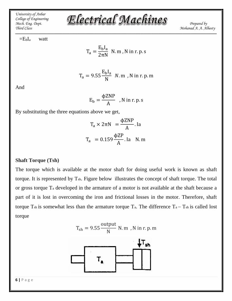
Shaft Torque (Tsh)
The torque which is available at the motor shaft for doing useful work is known as shaft
torque. It is represented by Tsh. Figure below illustrates the concept of shaft torque. The total
or gross torque Ta developed in the armature of a motor is not available at the shaft because a
part of it is lost in overcoming the iron and frictional losses in the motor. Therefore, shaft
torque Tsh is somewhat less than the armature torque Ta. The difference Ta − Tsh is called lost
torque
Tsh = 9.55output
N N. m , N in r. p. m
University of Anbar College of Engineering Mech. Eng. Dept. Prepared by Third Class Mohanad A. A. Alheety
ـــــــــــــــــــــــــــــــــــــــــــــــــــــــــــــــــــــــــــــــــــــــــــــــــــــــــــــــــــــــــــــــــــــــــــــــــــــــــــــــــــــــــــــــــــــــــــــــــــــــــــــــــــــــــــــــــــــــــ
7 | P a g e
Ex2: Determine developed torque and shaft torque of 220-V, 4-pole series motor with 800
conductors wave-connected supplying a load of 8.2 kW by taking 45 A from the mains. The
flux per pole is 25 mWb and its armature circuit resistance is 0.6 Ω.
Solution
Developed torque or gross torque is the same thing as armature torque.
Ta = 0.159ϕZP
A. Ia
Ta = 0.1590.025 × 800 × 4
2× 45 = 286.2 N. m
Eb = V − Ia Ra = 220 − 45× 0.6 = 193 V
Eb =ϕ P N
60 Z
A
193 =0.025 × 4 × N
60 800
2→ N = 289.5 r. p. m
Output = 2πNTsh
8200 = 2π ×289.5
60Tsh →→ Tsh = 270.5 N. m
Speed of a DC motor
N = Eb𝐴 × 60
ϕZP →→→ N = K
Eb
ϕ
It shows that speed is directly proportional to back e.m.f. Eb and inversely to the flux ϕ
N α Eb
ϕ

University of Anbar College of Engineering Mech. Eng. Dept. Prepared by Third Class Mohanad A. A. Alheety
ـــــــــــــــــــــــــــــــــــــــــــــــــــــــــــــــــــــــــــــــــــــــــــــــــــــــــــــــــــــــــــــــــــــــــــــــــــــــــــــــــــــــــــــــــــــــــــــــــــــــــــــــــــــــــــــــــــــــــ
8 | P a g e
For series and shunt motor,
Let N1 = Speed in the 1st case ; Ia1 = armature current in the 1st case
ϕ 1= flux/pole in the first case
N2,Ia2, ϕ 2 = corresponding quantities in the 2nd case.
Then, using the above relation, we get
N1 α Eb1
ϕ 1 where Eb1 = V − Ia1Ra
N2 α Eb2
ϕ 2 where Eb2 = V − Ia2Ra
N2
N1=
Eb2
Eb1×
ϕ 1ϕ 2
Also,
Ta = 0.159ϕZP
A. Ia
Ta = K ϕIa
Taα ϕIa
Ta2
Ta1=
Ia2
Ia1 ϕ2
ϕ1

University of Anbar College of Engineering Mech. Eng. Dept. Prepared by Third Class Mohanad A. A. Alheety
ـــــــــــــــــــــــــــــــــــــــــــــــــــــــــــــــــــــــــــــــــــــــــــــــــــــــــــــــــــــــــــــــــــــــــــــــــــــــــــــــــــــــــــــــــــــــــــــــــــــــــــــــــــــــــــــــــــــــــ
9 | P a g e
Speed Regulation
The speed regulation of a motor is the change in speed from full-load to no-loud
and is expressed as a percentage of the speed at full-load
% speed regulation =N. L speed − F. L speed
F. L speed . 100
Ex3: A 250-V shunt motor runs at 1000 r.p.m. at no-load and takes 8A. The total armature and
shunt field resistances are respectively 0.2 Ω and 250 Ω. Calculate the speed when loaded and
taking 50 A. Assume the flux to be constant.
Solution:
N2
N1=
Eb2
Eb1×
ϕ 1ϕ 2
Ish =250
250= 1A
Eb1 = 250 − (7 × 0.2) = 248.6 V
Eb2 = 250 − (49 × 0.2) = 240.2 V
N2
1000=
240.2
248.6× 1 →→ N2 = 9666 r. p. m

University of Anbar College of Engineering Mech. Eng. Dept. Prepared by Third Class Mohanad A. A. Alheety
ـــــــــــــــــــــــــــــــــــــــــــــــــــــــــــــــــــــــــــــــــــــــــــــــــــــــــــــــــــــــــــــــــــــــــــــــــــــــــــــــــــــــــــــــــــــــــــــــــــــــــــــــــــــــــــــــــــــــــ
10 | P a g e
Ex4:A 220V d.c. shunt motor runs at 500 r.p.m. when the armature current is 50 A.Calculate t
he speed if the torque is doubled. Given that Ra = 0.2 Ω (neglect armature reaction).
Solution:
Taα ϕIa
since ϕ is constant, Taα Ia
Ta1α Ia1 , Ta2α Ia2
Ta2
Ta1=
Ia2
Ia1
2 =Ia2
50 →→ Ia2 = 100A
Now,
N2
N1=
Eb2
Eb1 since ϕ is constant
Eb1 = 220 -50x0.2=210v
Eb2 = 220 -100x0.2=200v
N2
500=
200
210 →→ N2 = 476 r. p. m
Ex5: A 230-V d.c. shunt motor has an armature resistance of 0.5 Ω and field resistance
of 115 Ω. At no load, the speed is 1,200 r.p.m. and the armature current 2.5 A. On application
of rated load, the speed drops to 1,120 r.p.m. Determine the line current and power input when
the motor delivers rated load.
Solution:
Eb1 = 230 − (0.5 × 2.5) = 228.75 V
Eb2 = 230 − 0.5 Ia2
N2
N1=
Eb2
Eb2

University of Anbar College of Engineering Mech. Eng. Dept. Prepared by Third Class Mohanad A. A. Alheety
ـــــــــــــــــــــــــــــــــــــــــــــــــــــــــــــــــــــــــــــــــــــــــــــــــــــــــــــــــــــــــــــــــــــــــــــــــــــــــــــــــــــــــــــــــــــــــــــــــــــــــــــــــــــــــــــــــــــــــ
11 | P a g e
1120
1200=
230 − 0.5Ia2
228.75
Ia2 = 33 A
Line current drawn by motor = Ia2 + Ish = 33 + (230/115) = 35 A
Power input at rated load = 230 × 35 = 8,050 W
Ex5: belt-driven 100-kW, shunt generator running at 300 r.p.m. on 220-V busbars continues to
run as a motor when the belt breaks, then taking 10 kW. What will be its speed ? Given
armature resistance = 0.025 Ω, field resistance = 60 Ω and contact drop under each brush = 1
V, Ignore armature reaction.
Solution:
As a generator,
I = 100,000/220 = 454.55 A
Ish = 220/60 = 3.67 A
Ia = I + Ish = 458.2 A
Ia Ra = 458.2 × 0.025 = 11.45
Eg = 220 + 11.45 + 2 × 1 = 233.45 V
As a motor,
Input line current = 10,000/220 = 45.45 A
Ish = 220/60 = 3.67 A

University of Anbar College of Engineering Mech. Eng. Dept. Prepared by Third Class Mohanad A. A. Alheety
ـــــــــــــــــــــــــــــــــــــــــــــــــــــــــــــــــــــــــــــــــــــــــــــــــــــــــــــــــــــــــــــــــــــــــــــــــــــــــــــــــــــــــــــــــــــــــــــــــــــــــــــــــــــــــــــــــــــــــ
12 | P a g e
Ia = 45.45 − 3.67 = 41.78 A
Ia Ra = 41.78 × 0.025=1.04 V
Eb = 220 − 1.04 − 2 = 216.96 V
Nb
Ng=
Eb
Eg×
ϕ g
ϕ b , ϕ g = ϕ b
N2
300=
216.9
233.4→→→ N2 = 279 r. p. m
Repeat the above example considering the armature reaction (weakens the field by 3%).
Speed Control of D.C. Shunt Motors
1. Flux control method
It is based on the fact that by varying the flux, the motor speed can be changed and hence the
name flux control method. In this method, a variable resistance (known as shunt field rheostat) is
placed in series with shunt field winding.
The shunt field rheostat reduces the shunt field current Ish and hence the flux .
Therefore, we can only raise the speed of the motor above the normal speed. Generally, this
method permits to increase the speed in the ratio 3:1.

University of Anbar College of Engineering Mech. Eng. Dept. Prepared by Third Class Mohanad A. A. Alheety
ـــــــــــــــــــــــــــــــــــــــــــــــــــــــــــــــــــــــــــــــــــــــــــــــــــــــــــــــــــــــــــــــــــــــــــــــــــــــــــــــــــــــــــــــــــــــــــــــــــــــــــــــــــــــــــــــــــــــــ
13 | P a g e
2. Armature control method
This method is based on the fact that by varying the voltage available across the armature, the
back e.m.f and hence the speed of the motor can be changed. This is done by inserting a
variable resistance RC (known as controller resistance) in series with the armature.
𝑁α V − 𝐼𝑎(𝑅𝑎 + 𝑅𝑐)
Due to voltage drop in the controller resistance, the back e.m.f. (Eb) is decreased. The highest
speed obtainable is that corresponding to RC = 0 i.e., normal speed. Hence, this method can
only provide speeds below the normal speed.
Speed Control of D.C. Series Motors
1. Flux control method (Field divertcrs)
The series winding are shunted by a variable resistance known as field diverter. Any desired
amount of current can be passed through the diverter by adjusting its resistance. Hence the
flux can be decreased and consequently, the speed of the motor increased.
University of Anbar College of Engineering Mech. Eng. Dept. Prepared by Third Class Mohanad A. A. Alheety
ـــــــــــــــــــــــــــــــــــــــــــــــــــــــــــــــــــــــــــــــــــــــــــــــــــــــــــــــــــــــــــــــــــــــــــــــــــــــــــــــــــــــــــــــــــــــــــــــــــــــــــــــــــــــــــــــــــــــــ
14 | P a g e
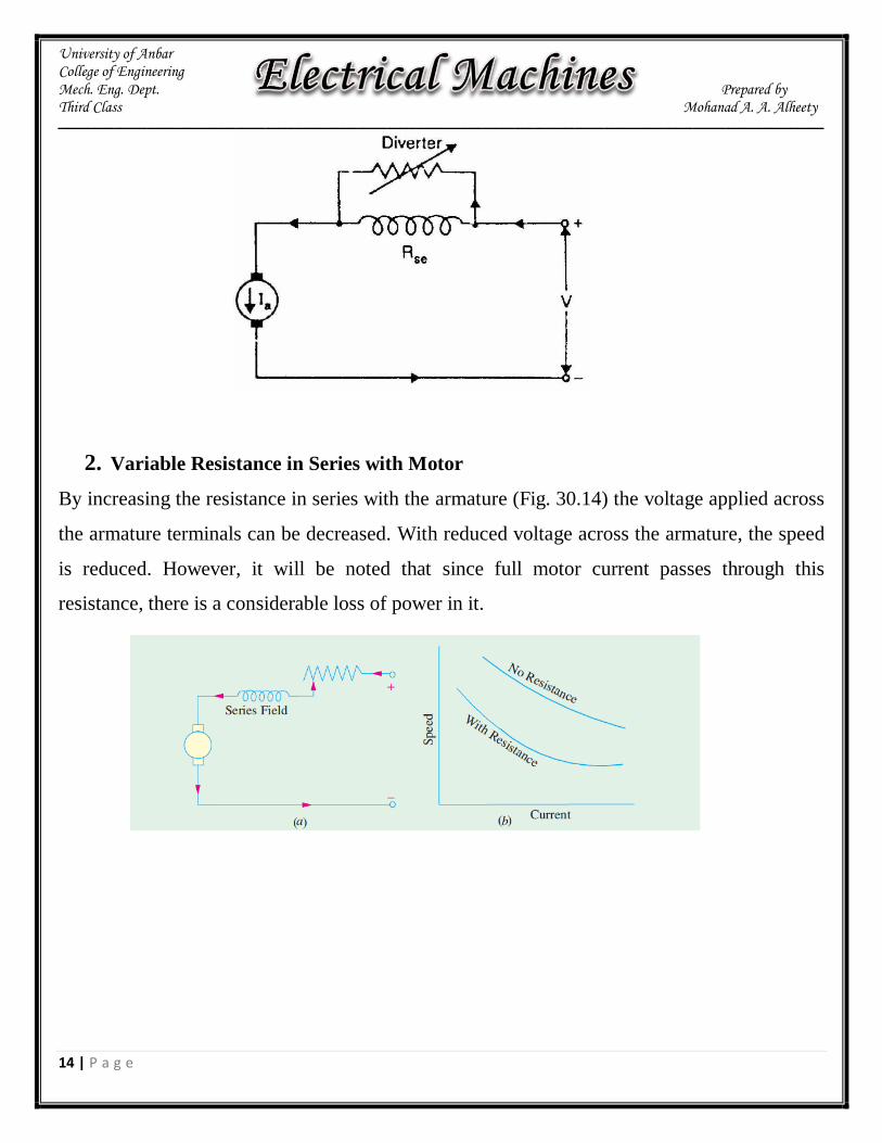
2. Variable Resistance in Series with Motor
By increasing the resistance in series with the armature (Fig. 30.14) the voltage applied across
the armature terminals can be decreased. With reduced voltage across the armature, the speed
is reduced. However, it will be noted that since full motor current passes through this
resistance, there is a considerable loss of power in it.

University of Anbar College of Engineering Mech. Eng. Dept. Prepared by Third Class Mohanad A. A. Alheety
ـــــــــــــــــــــــــــــــــــــــــــــــــــــــــــــــــــــــــــــــــــــــــــــــــــــــــــــــــــــــــــــــــــــــــــــــــــــــــــــــــــــــــــــــــــــــــــــــــــــــــــــــــــــــــــــــــــــــــ
15 | P a g e
Applications of D.C. Motors
Type of motor Characteristics Applications
Shunt
Approximately constant speed
Medium starting torque (Up
to 1.5 F.L. torque)
For driving constant speed line
shafting
Lathes
Centrifugal pumps
Machine tools
Blowers and fans
Reciprocating pumps
Series
Variable speed
Adjustable varying speed
High Starting torque
For traction work i.e.
Electric locomotives
Rapid transit systems
Trolley, cars etc.
Cranes and hoists
Conveyors
Compound
Variable speed
Adjustable varying speed
High starting torque
For intermittent high torque loads
For shears and punches
Elevators
Conveyors
Heavy planers
Heavy planers
Rolling mills; Ice machines;
Printing
presses; Air compressors

University of Anbar College of Engineering Mech. Eng. Dept. Prepared by Third Class Mohanad A. A. Alheety
ـــــــــــــــــــــــــــــــــــــــــــــــــــــــــــــــــــــــــــــــــــــــــــــــــــــــــــــــــــــــــــــــــــــــــــــــــــــــــــــــــــــــــــــــــــــــــــــــــــــــــــــــــــــــــــــــــــــــــ
16 | P a g e
Power stages
The various stages of energy transformation in a motor and also the various losses occurring
in it are shown in the following figure.
Overall or commercial efficiency 𝜂𝑐 = C/A
Electrical efficiency 𝜂𝑒 =B/A
Mechanical efficiency 𝜂𝑚=C/B
The condition for maximum efficiency is that armature Cu losses are equal to constant losses.
𝐼𝑎2Ra = constant losses
Ex6: A 4-pole, 240 V, wave connected shunt motor gives 11.19 kW when running at 1000
r.p.m. and drawing armature and field currents of 50 A and 1.0 A respectively. It has 540
conductors. Its resistance is 0.1 Ω. Assuming a drop of 1 volt per brush, find (a) total torque
(b) useful torque (c) useful flux / pole and (d) efficiency.
Solution:
Eb = V− Ia Ra − brush drop = 240 − (50× 0.1) − 2 = 233 V
Also, Ia = 50 A
Ta = 9.55EbIa
N

University of Anbar College of Engineering Mech. Eng. Dept. Prepared by Third Class Mohanad A. A. Alheety
ـــــــــــــــــــــــــــــــــــــــــــــــــــــــــــــــــــــــــــــــــــــــــــــــــــــــــــــــــــــــــــــــــــــــــــــــــــــــــــــــــــــــــــــــــــــــــــــــــــــــــــــــــــــــــــــــــــــــــ
17 | P a g e
= 9.55233 × 50
1000= 111 𝑁. 𝑚
Tsh = 9.55output
N= 9.55 ×
11190
1000= 106.7 N. m
Eb =ϕ P N
60 Z
A
233 =ϕ × 4 × 1000
60 540
2 →→ ϕ = 12.9 Wb
Total motor input = VI = 240 × 51 = 12,340 W
Efficiency= 11190/12340=90.6%.
Ex7: A 200-V, d.c. shunt motor takes 4 A at no-load when running at 700 r.p.m. The field
resistance is 100 Ω and the resistance of armature is 0.6 ohms. Calculate (a) speed on load (b)
torque in N-m and (c) efficiency (d) armature current when efficiency is maximum. The
normal input of the motor is 8 kW. Neglect armature reaction.
Solution:
(a) Ish = 200/100 = 2 A
F.L. Power input = 8,000 W
F.L. line current = 8,000/200 = 40 A
Ia = 40 − 2 = 38 A
Ebo = 200 − 2 × 0.6= 198.8 V
Eb = 200 − 38 ×0.6 = 177.2 V

University of Anbar College of Engineering Mech. Eng. Dept. Prepared by Third Class Mohanad A. A. Alheety
ـــــــــــــــــــــــــــــــــــــــــــــــــــــــــــــــــــــــــــــــــــــــــــــــــــــــــــــــــــــــــــــــــــــــــــــــــــــــــــــــــــــــــــــــــــــــــــــــــــــــــــــــــــــــــــــــــــــــــ
18 | P a g e
N
N0=
Eb
Ebo
N
700=
177.2
198.8→→ N = 924 r. p. m
(b) Ta = 9.55 EbIa/N = 9.55 × 177.2 × 38/623.9 = 103 N-m
(c) N.L. power input = 200 ×4 = 800 W
N.L Arm. Cu loss = Ia2 Ra = 22 × 0.6 = 2.4 W
Constant losses = N.L. power input- N.L Arm. Cu loss
=800-2.4=797.6 W
F.L. arm. Cu loss = 38×38× 0.6 = 866.4 W
Total F.L. losses = Constant losses+ F.L. arm. Cu loss
=797.6 + 866.4 = 1664 W
F.L. output = F.L. Power input− Total F.L. losses
=8000-1664 = 6336 W
F.L. Motor efficiency = 6336/8,000=79.2%
(d) When efficiency is maximum,
Ia2Ra = constant losses
Ia2 × 0.6 = 797.6 →→ Ia = 36.5 A

University of Anbar College of Engineering Mech. Eng. Dept. Prepared by Third Class Mohanad A. A. Alheety
ـــــــــــــــــــــــــــــــــــــــــــــــــــــــــــــــــــــــــــــــــــــــــــــــــــــــــــــــــــــــــــــــــــــــــــــــــــــــــــــــــــــــــــــــــــــــــــــــــــــــــــــــــــــــــــــــــــــــــ
19 | P a g e
Ex8: A 500-V D.C. shunt motor draws a line-current of 5 A on light-load. If armature
resistance is 0.15 ohm and field resistance is 200 ohms determine the efficiency of the
machine running as a generator delivering a load current of 40 A. At what speed should the
generator be run if the shunt-field is not changed in the above case? Assume that the motor
was running at 600 r.p.m.
Solution:
(i) No Load, running as a motor :
Input Power = 500 × 5 = 2500 watts
Neglecting armature copper-loss at no load (since it comes out to be 2.52× 0.15 = 1 watt)
(ii) As a Generator, delivering 40 A to load :
Output delivered = 500 × 40 × 103= 20 kW
Losses :
(a) Armature copper-loss = 42.52× 0.15 = 271 watts
(b) No load losses = 2500 watts
Total losses = 2.771 kW
Generator Efficiency = (20/22.771) × 100 % = 87.83 %.
As a motor on no-load,
Eb0 = 500 − Ia× Ra = 500 − 0.15×2.5 = 499.625 V
As a Generator with an armature current of 42.5 A,
Eg0 = 500 + 42.5 0.15 = 506.375 V

University of Anbar College of Engineering Mech. Eng. Dept. Prepared by Third Class Mohanad A. A. Alheety
ـــــــــــــــــــــــــــــــــــــــــــــــــــــــــــــــــــــــــــــــــــــــــــــــــــــــــــــــــــــــــــــــــــــــــــــــــــــــــــــــــــــــــــــــــــــــــــــــــــــــــــــــــــــــــــــــــــــــــ
20 | P a g e
Since, the terminal voltage is same in both the cases, shunt field current remains as 2.5 amp.
With armature reaction is ignored, the flux/pole remains same. The e.m.f. then becomes
proportional to the speed. If the generator must be driven at N r.p.m.
N = (506.375/449.625) × 600 = 608.1 r.p.m.
Ex9: A 7.46 kW, 250-V shunt motor takes a line current of 5 A when running light.
Calculate the efficiency as a motor when delivering full load output, if the armature and field
resistance are 0.5 Ω and 250 Ω respectively. At what output power will the efficiency be
maximum? Is it possible to obtain this output from the machine?
Solution:
Total motor input (or total no − load losses) = 250 × 5 = 1,250 W
Ish = 250/250 = IA ∴ Ia = 5 − 1 = 4 A
Field Cu loss = 250 × 1 = 250 W;
Armature Cu loss = 42 × 0.5 = 8 W
Iron losses and friction losses = 1250 − 250 − 8 = 992 W
These losses would be assumed constant.
Let Ia be the full-load armature current, then armature input is = (250 × Ia) W
F.L. output = 7.46 × 1000 = 7,460 W
Armature Cu loss = 𝐼𝑎2 × 0.05 W
250 Ia = 7,460 + 992 + I𝑎2 × 0.5
Ia = 36.5 A
F.L. input current = 36.5 + 1 = 37.5 A
Motor input = 250 × 37.5 W
F.L. efficiency = 7460 × 100/250 × 37.5 = 79.6%
Rest of the solution is H.W.