
CHAPTER OBJECTIVES
45
1 005 Pearson Education South Asia Pte Ltd 1. Stress CHAPTER OBJECTIVES • Review important principles of statics • Use the principles to determine internal resultant loadings in a body • Introduce concepts of normal and shear stress • Discuss applications of analysis and design of members subjected to an axial load or direct shear
-
Upload
herrod-garza -
Category
Documents
-
view
15 -
download
0
description
CHAPTER OBJECTIVES. Review important principles of statics Use the principles to determine internal resultant loadings in a body Introduce concepts of normal and shear stress. Discuss applications of analysis and design of members subjected to an axial load or direct shear. CHAPTER OUTLINE. - PowerPoint PPT Presentation
Transcript of CHAPTER OBJECTIVES

12005 Pearson Education South Asia Pte Ltd
1. Stress
CHAPTER OBJECTIVES
• Review important principles of statics
• Use the principles to determine internal resultant loadings in a body
• Introduce concepts of normal and shear stress
• Discuss applications of analysis and design of members subjected to an axial load or direct shear

22005 Pearson Education South Asia Pte Ltd
1. Stress
CHAPTER OUTLINE
1. Introduction
2. Equilibrium of a deformable body
3. Stress
4. Average normal stress in an axially loaded bar
5. Average shear stress
6. Allowable stress
7. Design of simple connections

32005 Pearson Education South Asia Pte Ltd
1. Stress
Mechanics of materials• A branch of mechanics• It studies the relationship of
– External loads applied to a deformable body, and
– The intensity of internal forces acting within the body
• Are used to compute deformations of a body• Study body’s stability when external forces are
applied to it
1.1 INTRODUCTION

42005 Pearson Education South Asia Pte Ltd
1. Stress
Historical development• Beginning of 17th century (Galileo)• Early 18th century (Saint-Venant, Poisson, Lamé
and Navier)• In recent times, with advanced mathematical and
computer techniques, more complex problems can be solved
1.1 INTRODUCTION
52005 Pearson Education South Asia Pte Ltd
1. Stress
1.2 EQUILIBRIUM OF A DEFORMABLE BODY
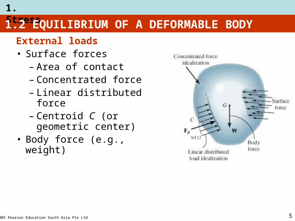
External loads• Surface forces
– Area of contact– Concentrated force– Linear distributed force– Centroid C (or
geometric center)• Body force (e.g., weight)

62005 Pearson Education South Asia Pte Ltd
1. Stress
Support reactions• for 2D problems
1.2 EQUILIBRIUM OF A DEFORMABLE BODY

72005 Pearson Education South Asia Pte Ltd
1. Stress
Equations of equilibrium• For equilibrium
– balance of forces– balance of moments
• Draw a free-body diagram to account for all forces acting on the body
• Apply the two equations to achieve equilibrium state
∑ F = 0
∑ MO = 0
1.2 EQUILIBRIUM OF A DEFORMABLE BODY

82005 Pearson Education South Asia Pte Ltd
1. Stress
Internal resultant loadings
• Define resultant force (FR) and moment (MRo) in 3D:
– Normal force, N– Shear force, V– Torsional moment or torque, T– Bending moment, M
1.2 EQUILIBRIUM OF A DEFORMABLE BODY
92005 Pearson Education South Asia Pte Ltd
1. Stress
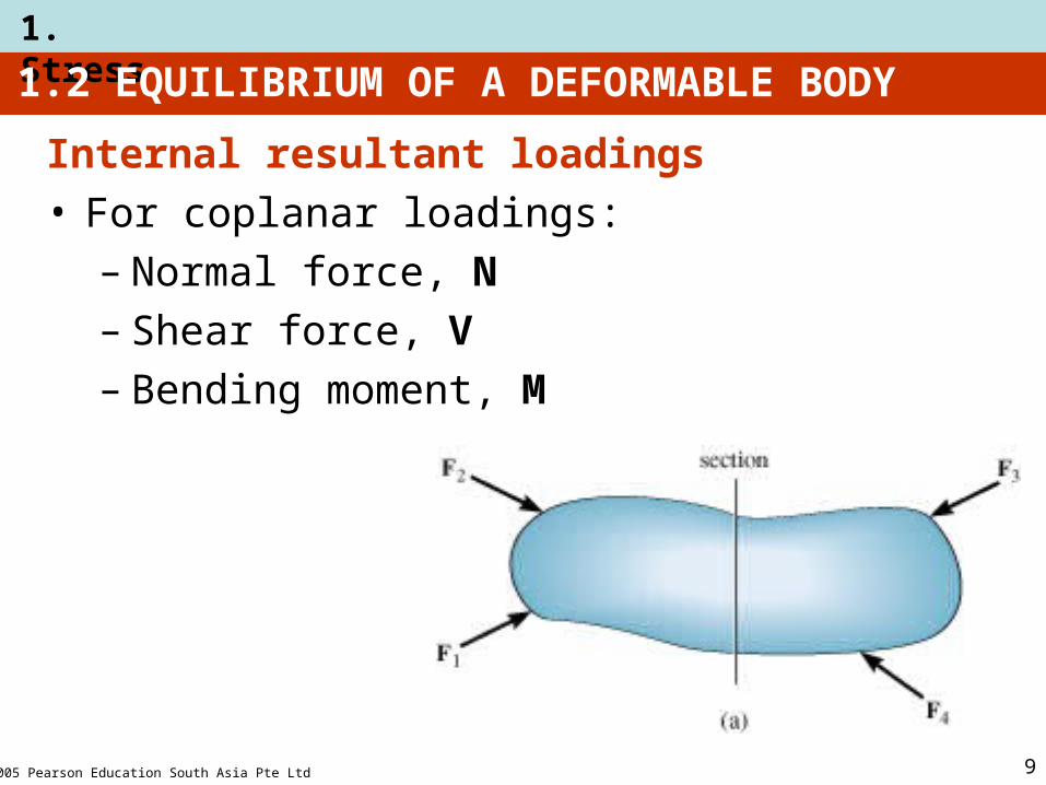
Internal resultant loadings• For coplanar loadings:
– Normal force, N– Shear force, V– Bending moment, M
1.2 EQUILIBRIUM OF A DEFORMABLE BODY

102005 Pearson Education South Asia Pte Ltd
1. Stress
Internal resultant loadings• For coplanar loadings:
– Apply ∑ Fx = 0 to solve for N
– Apply ∑ Fy = 0 to solve for V
– Apply ∑ MO = 0 to solve for M
1.2 EQUILIBRIUM OF A DEFORMABLE BODY
112005 Pearson Education South Asia Pte Ltd
1. Stress
Procedure for analysis• Method of sections
1. Choose segment to analyze
2. Determine Support Reactions
3. Draw free-body diagram for whole body
4. Apply equations of equilibrium
1.2 EQUILIBRIUM OF A DEFORMABLE BODY

122005 Pearson Education South Asia Pte Ltd
1. Stress
Procedure for analysis• Free-body diagram
1. Keep all external loadings in exact locations before “sectioning”
2. Indicate unknown resultants, N, V, M, and T at the section, normally at centroid C of sectioned area
3. Coplanar system of forces only include N, V, and M
4. Establish x, y, z coordinate axes with origin at centroid
1.2 EQUILIBRIUM OF A DEFORMABLE BODY

132005 Pearson Education South Asia Pte Ltd
1. Stress
Procedure for analysis• Equations of equilibrium
1. Sum moments at section, about each coordinate axes where resultants act
2. This will eliminate unknown forces N and V, with direct solution for M (and T)
3. Resultant force with negative value implies that assumed direction is opposite to that shown on free-body diagram
1.2 EQUILIBRIUM OF A DEFORMABLE BODY

142005 Pearson Education South Asia Pte Ltd
1. Stress
EXAMPLE 1.1
Determine resultant loadings acting on cross section at C of beam.

152005 Pearson Education South Asia Pte Ltd
1. Stress
EXAMPLE 1.1 (SOLN)
Support reactions• Consider segment CB
Free-body diagram:• Keep distributed loading exactly where it is on
segment CB after “cutting” the section. • Replace it with a single resultant force, F.
162005 Pearson Education South Asia Pte Ltd
1. Stress
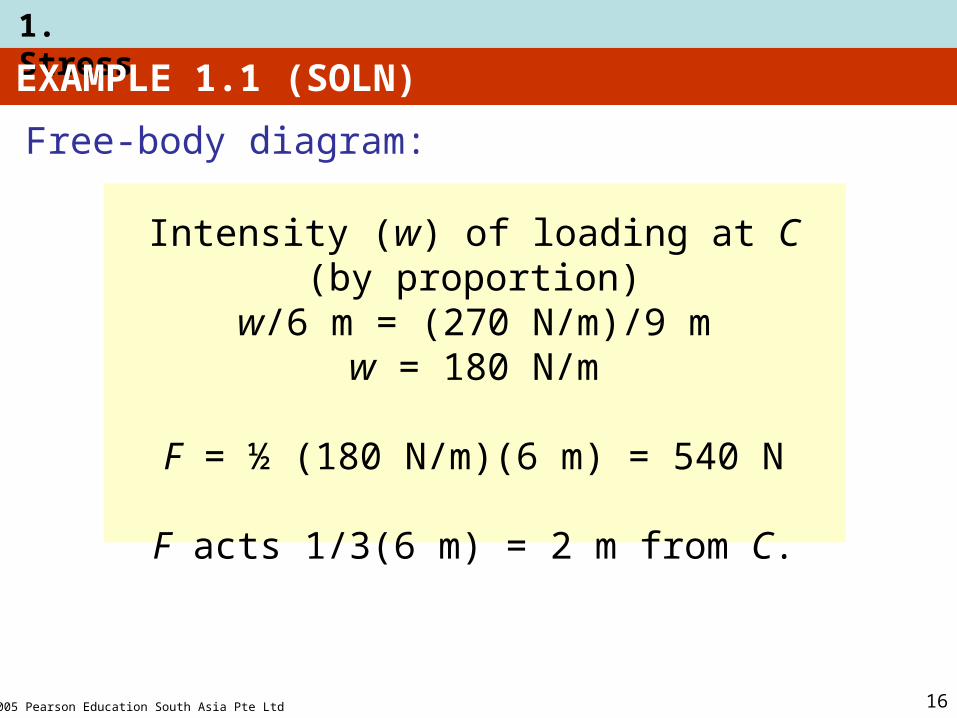
EXAMPLE 1.1 (SOLN)
Intensity (w) of loading at C (by proportion)w/6 m = (270 N/m)/9 m
w = 180 N/m
F = ½ (180 N/m)(6 m) = 540 N
F acts 1/3(6 m) = 2 m from C.
Free-body diagram:

172005 Pearson Education South Asia Pte Ltd
1. Stress
EXAMPLE 1.1 (SOLN)
Equilibrium equations:
∑ Fx = 0;
∑ Fy = 0;
∑ Mc = 0;
− Nc = 0Nc = 0
Vc − 540 N = 0Vc = 540 N
−Mc − 504 N (2 m) = 0Mc = −1080 N·m
+
+
+

182005 Pearson Education South Asia Pte Ltd
1. Stress
EXAMPLE 1.1 (SOLN)
Equilibrium equations:
Negative sign of Mc means it acts in the opposite direction to that shown below

192005 Pearson Education South Asia Pte Ltd
1. Stress
EXAMPLE 1.5
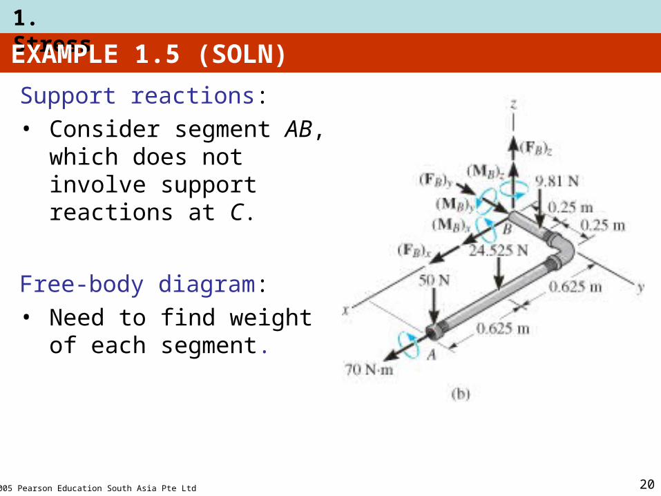
Mass of pipe = 2 kg/m, subjected to vertical force of 50 N and couple moment of 70 N·m at end A. It is fixed to the wall at C.
Determine resultant internal loadings acting on cross section at B of pipe.
202005 Pearson Education South Asia Pte Ltd
1. Stress
EXAMPLE 1.5 (SOLN)
Support reactions: • Consider segment AB,
which does not involve support reactions at C.
Free-body diagram:• Need to find weight of
each segment.

212005 Pearson Education South Asia Pte Ltd
1. Stress
EXAMPLE 1.5 (SOLN)
WBD = (2 kg/m)(0.5 m)(9.81 N/kg) = 9.81 N
WAD = (2 kg/m)(1.25 m)(9.81 N/kg) = 24.525 N
222005 Pearson Education South Asia Pte Ltd
1. Stress
EXAMPLE 1.5 (SOLN)
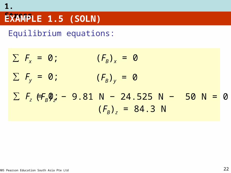
Equilibrium equations:
∑ Fx = 0;
∑ Fy = 0;
(FB)x = 0
(FB)y = 0
∑ Fz = 0; (FB)z − 9.81 N − 24.525 N − 50 N = 0(FB)z = 84.3 N

232005 Pearson Education South Asia Pte Ltd
1. Stress
EXAMPLE 1.5 (SOLN)
Equilibrium equations:
∑ (MB)x = 0;
(Mc)x + 70 N·m − 50 N (0.5 m) − 24.525 N (0.5 m) − 9.81 N (0.25m) = 0
(MB)x = − 30.3 N·m
∑ (MB)y = 0;(Mc)y + 24.525 N (0.625·m) + 50 N (1.25 m) = 0
(MB)y = − 77.8 N·m
∑(MB)z = 0; (Mc)z = 0

242005 Pearson Education South Asia Pte Ltd
1. Stress
EXAMPLE 1.5 (SOLN)
NB = (FB)y = 0
VB = √ (0)2 + (84.3)2 = 84.3 N
TB = (MB)y = 77.8 N·m
MB = √ (30.3)2 + (0)2 = 30.3 N·m
The direction of each moment is determined using the right-hand rule: positive moments (thumb) directed along positive coordinate axis
Equilibrium equations:

252005 Pearson Education South Asia Pte Ltd
1. Stress
1.3 STRESS
Concept of stress• To obtain distribution of force acting over a
sectioned area • Assumptions of material:
1. It is continuous (uniform distribution of matter)
2. It is cohesive (all portions are connected together)

262005 Pearson Education South Asia Pte Ltd
1. Stress
1.3 STRESS
Concept of stress• Consider ΔA in figure below• Small finite force, ΔF acts on ΔA• As ΔA → 0, Δ F → 0
• But stress (ΔF / ΔA) → finite limit (∞)

272005 Pearson Education South Asia Pte Ltd
1. Stress
Normal stress• Intensity of force, or force per unit area, acting
normal to ΔA
• Symbol used for normal stress, is σ (sigma)
• Tensile stress: normal force “pulls” or “stretches” the area element ΔA
• Compressive stress: normal force “pushes” or “compresses” area element ΔA
1.3 STRESS
σz =lim
ΔA →0
ΔFz
ΔA

282005 Pearson Education South Asia Pte Ltd
1. Stress
Shear stress• Intensity of force, or force per unit area, acting
tangent to ΔA• Symbol used for normal stress is τ (tau)
1.3 STRESS
τzx =lim
ΔA →0
ΔFx
ΔA
τzy =lim
ΔA →0
ΔFy
ΔA

292005 Pearson Education South Asia Pte Ltd
1. Stress
General state of stress• Figure shows the state of stress
acting around a chosen point in a body
Units (SI system)• Newtons per square meter (N/m2)
or a pascal (1 Pa = 1 N/m2)• kPa = 103 N/m2 (kilo-pascal)• MPa = 106 N/m2 (mega-pascal)• GPa = 109 N/m2 (giga-pascal)
1.3 STRESS

302005 Pearson Education South Asia Pte Ltd
1. Stress
1.4 AVERAGE NORMAL STRESS IN AXIALLY LOADED BAR
Examples of axially loaded bar• Usually long and slender structural members• Truss members, hangers, bolts• Prismatic means all the cross sections are the same

312005 Pearson Education South Asia Pte Ltd
1. Stress
Assumptions
1. Uniform deformation: Bar remains straight before and after load is applied, and cross section remains flat or plane during deformation
2. In order for uniform deformation, force P be applied along centroidal axis of cross section
1.4 AVERAGE NORMAL STRESS IN AXIALLY LOADED BAR

322005 Pearson Education South Asia Pte Ltd
1. Stress
Average normal stress distribution
σ = average normal stress at any point on cross sectional area
P = internal resultant normal forceA = x-sectional area of the bar
1.4 AVERAGE NORMAL STRESS IN AXIALLY LOADED BAR
FRz = ∑ Fxz ∫ dF = ∫A σ dA
P = σ A
+
PA
σ =

332005 Pearson Education South Asia Pte Ltd
1. Stress
Equilibrium• Consider vertical equilibrium of the element
∑ Fz = 0 σ (ΔA) − σ’ (ΔA) = 0σ = σ’
Above analysis applies to members subjected to tension or compression.
1.4 AVERAGE NORMAL STRESS IN AXIALLY LOADED BAR
342005 Pearson Education South Asia Pte Ltd
1. Stress
Maximum average normal stress• For problems where internal force P and x-
sectional A were constant along the longitudinal axis of the bar, normal stress σ = P/A is also constant
• If the bar is subjected to several external loads along its axis, change in x-sectional area may occur
• Thus, it is important to find the maximum average normal stress
• To determine that, we need to find the location where ratio P/A is a maximum
1.4 AVERAGE NORMAL STRESS IN AXIALLY LOADED BAR

352005 Pearson Education South Asia Pte Ltd
1. Stress
Maximum average normal stress• Draw an axial or normal force diagram (plot of
P vs. its position x along bar’s length)• Sign convention:
– P is positive (+) if it causes tension in the member
– P is negative (−) if it causes compression• Identify the maximum average normal stress
from the plot
1.4 AVERAGE NORMAL STRESS IN AXIALLY LOADED BAR

362005 Pearson Education South Asia Pte Ltd
1. Stress
Procedure for analysisAverage normal stress• Use equation of σ = P/A for x-sectional area of a
member when section subjected to internal resultant force P
1.4 AVERAGE NORMAL STRESS IN AXIALLY LOADED BAR

372005 Pearson Education South Asia Pte Ltd
1. Stress
Procedure for analysisAxially loaded members• Internal Loading: • Section member perpendicular to its longitudinal
axis at pt where normal stress is to be determined
• Draw free-body diagram• Use equation of force equilibrium to obtain
internal axial force P at the section
1.4 AVERAGE NORMAL STRESS IN AXIALLY LOADED BAR

382005 Pearson Education South Asia Pte Ltd
1. Stress
Procedure for AnalysisAxially loaded members• Average Normal Stress: • Determine member’s x-sectional area at the
section• Compute average normal stress σ = P/A
1.4 AVERAGE NORMAL STRESS IN AXIALLY LOADED BAR

392005 Pearson Education South Asia Pte Ltd
1. Stress
EXAMPLE 1.6
Bar width = 35 mm, thickness = 10 mm
Determine max. average normal stress in bar when subjected to loading shown.

402005 Pearson Education South Asia Pte Ltd
1. Stress
EXAMPLE 1.6 (SOLN)
Internal loading
Normal force diagram
By inspection, largest loading area is BC, where PBC = 30 kN

412005 Pearson Education South Asia Pte Ltd
1. Stress
EXAMPLE 1.6 (SOLN)
Average normal stress
σBC =PBC
A
30(103) N
(0.035 m)(0.010 m)= = 85.7 MPa

422005 Pearson Education South Asia Pte Ltd
1. Stress
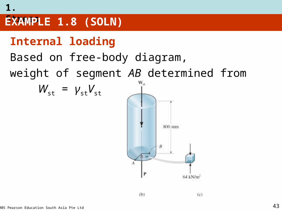
EXAMPLE 1.8
Specific weight γst = 80 kN/m3
Determine average compressive stress acting at points A and B.
432005 Pearson Education South Asia Pte Ltd
1. Stress
EXAMPLE 1.8 (SOLN)
Internal loading
Based on free-body diagram,
weight of segment AB determined from
Wst = γstVst

442005 Pearson Education South Asia Pte Ltd
1. Stress
EXAMPLE 1.8 (SOLN)
Average normal stress
+ ∑ Fz = 0; P − Wst = 0
P − (80 kN/m3)(0.8 m)(0.2 m)2 = 0
P = 8.042 kN

452005 Pearson Education South Asia Pte Ltd
1. Stress
EXAMPLE 1.8 (SOLN)
Average compressive stress
Cross-sectional area at section:
A = (0.2)m2
8.042 kN
(0.2 m)2
P
A=σ =
σ = 64.0 kN/m2